JP6179065B2 - Pulse wave measurement device and detection device - Google Patents
Pulse wave measurement device and detection device Download PDFInfo
- Publication number
- JP6179065B2 JP6179065B2 JP2012015262A JP2012015262A JP6179065B2 JP 6179065 B2 JP6179065 B2 JP 6179065B2 JP 2012015262 A JP2012015262 A JP 2012015262A JP 2012015262 A JP2012015262 A JP 2012015262A JP 6179065 B2 JP6179065 B2 JP 6179065B2
- Authority
- JP
- Japan
- Prior art keywords
- light
- region
- unit
- signal
- pulse wave
- Prior art date
- Legal status (The legal status is an assumption and is not a legal conclusion. Google has not performed a legal analysis and makes no representation as to the accuracy of the status listed.)
- Active
Links
Images


Description
本発明は、生体の脈波を測定する技術に関する。 The present invention relates to a technique for measuring a pulse wave of a living body.
光を用いて生体の脈派を測定する技術が知られている。例えば、特許文献1には、パルスフォトメータにおいて、同一の媒体から抽出される2つの測定信号から、脈波信号とアーチフェクト信号とを分離する信号処理方法が記載されている。
A technique for measuring the pulse of a living body using light is known. For example,
二波長の光を用いて脈派を測定する場合、これらの光が生体内の異なる領域で反射されると、異なる部位を観測していることになるため、脈波の測定に誤差が生じてしまう。
本発明は、生体内の同じ領域で反射される光を用いて脈波を測定することを目的の1つとする。
When measuring pulse waves using light of two wavelengths, if these lights are reflected from different areas in the living body, different parts will be observed, resulting in errors in pulse wave measurement. End up.
An object of the present invention is to measure a pulse wave using light reflected from the same region in a living body.
本発明に係る脈波想定装置は、生体内の第1の領域に第1の光を照射する第1の照射部と、前記第1の領域と共通する領域を有する前記生体内の第2の領域に、前記第1の光と波長の異なる第2の光を照射する第2の照射部と、前記共通する領域の少なくとも一部で反射された第1の光及び第2の光を受け入れる開口部を有し、当該開口部により受け入れられた第1の光及び第2の光を集光する集光部と、前記集光部により集光された前記第1の光を受光し、当該受光した第1の光を第1の信号に変換する第1の受光部と、前記集光部により集光された前記第2の光を受光し、当該受光した第2の光を第2の信号に変換する第2の受光部と、前記第1の信号及び前記第2の信号に基づいて、前記生体の脈波を検出する検出部とを備えることを特徴とする。この構成によれば、生体内の同じ領域で反射される光を用いて脈波を測定することができる。 The pulse wave assumption device according to the present invention includes a first irradiating unit that irradiates a first region in a living body with a first light, and a second in-vivo having a region in common with the first region. A second irradiation unit that irradiates the region with second light having a wavelength different from that of the first light, and an opening that receives the first light and the second light reflected by at least a part of the common region. A light collecting portion for collecting the first light and the second light received by the opening, and receiving the first light collected by the light collecting portion. A first light receiving unit that converts the first light into a first signal, the second light collected by the light collecting unit, and the received second light as a second signal. A second light-receiving unit that converts the signal into a first wave, and a detection unit that detects a pulse wave of the living body based on the first signal and the second signal. And butterflies. According to this configuration, the pulse wave can be measured using light reflected from the same region in the living body.
前記集光部は、前記第1の受光部及び前記第2の受光部を覆うドーム状の反射板であってもよい。この構成によれば、第1の光び第2の光を効率よく集光することができる。 The condensing unit may be a dome-shaped reflecting plate that covers the first light receiving unit and the second light receiving unit. According to this configuration, it is possible to efficiently collect the first light and the second light.
前記開口部に設けられ、前記共通する領域のうち前記開口部と対向する領域で反射された前記第1の光及び前記第2の光を通過させるスリットを有し、前記対向する領域以外の領域で反射された前記第1の光及び前記第2の光を遮断するスリット板を備えてもよい。この構成によれば、開口部と対向する領域で反射される光を用いて脈波を測定することができる。 An area other than the opposed area, having a slit that is provided in the opening and allows the first light and the second light reflected in the common area to be reflected by the area facing the opening. There may be provided a slit plate that blocks the first light and the second light reflected at. According to this configuration, the pulse wave can be measured using the light reflected by the region facing the opening.
前記スリット板は、線状の複数のスリットを有し、前記複数のスリットは、前記スリット板の面の1の方向に沿って配列されてもよい。この構成によれば、スリットを通過する光量の減少を抑制することができる。 The slit plate may have a plurality of linear slits, and the plurality of slits may be arranged along one direction of the surface of the slit plate. According to this configuration, it is possible to suppress a decrease in the amount of light passing through the slit.
前記スリット板は、四角形又は円形の複数のスリットを有し、前記複数のスリットは、前記スリット板の面に沿って2次元配列されてもよい。この構成によれば、スリットを通過する光量の減少を抑制することができる。 The slit plate may include a plurality of square or circular slits, and the plurality of slits may be two-dimensionally arranged along the surface of the slit plate. According to this configuration, it is possible to suppress a decrease in the amount of light passing through the slit.
前記第1の光の波長は、前記第2の光の波長よりも小さく、前記第1の照射部と前記第1の受光部との間の距離は、前記第2の照射部と前記第2の受光部との間の第2の距離よりも大きくてもよい。この構成によれば、二波長の光を用いて脈波を測定する構成において、生体内の同じ領域で反射される光を用いて脈波を測定することができる。 The wavelength of the first light is smaller than the wavelength of the second light, and the distance between the first irradiation unit and the first light receiving unit is the second irradiation unit and the second light. It may be larger than the second distance between the light receiving unit. According to this configuration, in a configuration in which a pulse wave is measured using light of two wavelengths, the pulse wave can be measured using light reflected from the same region in the living body.
本発明に係る検出装置は、生体内の第1の領域に第1の光を照射する第1の照射部と、前記第1の領域と共通する領域を有する前記生体内の第2の領域に、前記第1の光と波長の異なる第2の光を照射する第2の照射部と、前記共通する領域の少なくとも一部で反射された第1の光及び第2の光を受け入れる開口部を有し、当該開口部により受け入れられた第1の光及び第2の光を集光する集光部と、前記集光部により集光された前記第1の光を受光し、当該受光した第1の光を第1の信号に変換する第1の受光部と、前記集光部により集光された前記第2の光を受光し、当該受光した第2の光を第2の信号に変換する第2の受光部とを備えることを特徴とする。この構成によれば、生体内の同じ領域で反射される光を用いて脈波を測定することができる。 The detection apparatus according to the present invention includes a first irradiation unit that irradiates a first region in a living body with a first light, and a second region in the living body that has a region common to the first region. A second irradiating unit for irradiating a second light having a wavelength different from that of the first light, and an opening for receiving the first light and the second light reflected by at least a part of the common region. A first light receiving unit configured to collect the first light and the second light received by the opening, and the first light collected by the light collecting unit to receive the first light. 1st light-receiving part which converts 1 light into a 1st signal, The said 2nd light condensed by the said condensing part is light-received, The said received 2nd light is converted into a 2nd signal And a second light receiving portion. According to this configuration, the pulse wave can be measured using light reflected from the same region in the living body.
図1は、本実施形態に係る脈波測定装置1の外観を示す図である。脈波測定装置1は、人間の手2に装着される。脈波測定装置1は、人間の手首に装着される装置本体3と、脈波センサー4(検出装置の一例)とで構成されている。この装置本体3と脈波センサー4とは、ケーブル5を介して接続されている。脈波センサー4は、図1(b)に示すように、人差指の根元の手のひら側にバンド6によって固定される。
FIG. 1 is a diagram illustrating an appearance of a pulse
図2は、脈波測定装置1の構成を示すブロック図である。脈波測定装置1は、二波長の光を用いて脈波を測定する。装置本体3は、CPU(Central Processing Unit)11(検出部の一例)と、ROM(Read Only Memory)12と、RAM(Random Access Memory)13と、表示部14と、操作部15と、発振回路16と、計時回路17と、第1の信号処理部21a及び第2の信号処理部21bとを備える。脈波センサー4は、駆動回路18と、第1の発光部19a(第1の照射部の一例)及び第2の発光部19b(第2の照射部の一例)と、第1の受光部20a及び第2の受光部20bとを備える。
FIG. 2 is a block diagram showing the configuration of the pulse
CPU11は、制御プログラムを実行して脈波測定装置1の各部を制御する。ROM12は、読み出し専用の不揮発性メモリーである。ROM12には、例えばCPU11により実行される基本的なシステムプログラムが記憶される。RAM13は、CPU11のワークエリアとして使用される揮発性メモリーである。RAM13には、例えばCPU11による制御プログラムの実行中に発生する各種のデータが一時的に記憶される。表示部14は、例えば液晶ディスプレイである。表示部14は、CPU11による制御の下、脈波の測定結果や脈波の測定に関する各種の情報を表示する。操作部15は、例えば脈波測定装置1の操作に用いられる複数の操作ボタンを備える。操作部15は、利用者の操作に応じた操作信号をCPU11に供給する。発振回路16は、CPU11にクロック信号を供給する。計時回路17は、CPU11による制御の下、時間を計測する。
The
駆動回路18は、第1の発光部19a及び第2の発光部19bを駆動する。例えば、駆動回路18は、操作部15を用いて脈波の測定開始を指示する操作が行われると、第1の発光部19aと第2の発光部19bとを交互に駆動する。第1の発光部19aは、緑色光Lg(第1の光の一例)を照射する発光素子を備える。この緑色光Lgのピーク波長は、525nmである。第2の発光部19bは、赤色光Lr(第2の光の一例)を照射する発光素子を備える。この赤色光Lrのピーク波長は、620nmである。緑色光Lgのピーク波長は、赤色光Lrのピーク波長よりも小さい。第1の発光部19a及び第2の発光部19bは、駆動回路18により駆動されると、生体内の部位に光を照射する。
The
第1の発光部19aから照射された緑色光Lgは、生体内の部位で反射され第1の受光部20aに到達する。第1の受光部20aは、第1の受光面22aを有する。第1の受光面22aの表面には、緑色光Lgを透過させるフィルターが設けられている。第1の受光面22aは、このフィルターを透過した緑色光Lgを受光する。第1の受光部20aは、第1の受光面22aで緑色光Lgを受光すると、受光した緑色光Lgを第1の信号に変換して出力する。
The green light Lg emitted from the first
第2の発光部19bから照射された赤色光Lrは、生体内の部位で反射され第2の受光部20bに到達する。第2の受光部20bは、第2の受光面22bを有する。第2の受光面22bの表面には、赤色光Lrを透過させるフィルターが設けられている。第2の受光面22bは、このフィルターを透過した赤色光Lrを受光する。第2の受光部20bは、第2の受光面22bで赤色光Lrを受光すると、受光した赤色光Lrを第2の信号に変換して出力する。
The red light Lr emitted from the second
第1の受光部20aから出力された第1の信号は、第1の信号処理部21aに入力される。第1の信号処理部21aは、第1の信号が入力されると、入力された第1の信号に各種の信号処理を施して出力する。この信号処理には、例えば信号増幅処理やA/D(analog to digital)変換処理が含まれる。第2の受光部20bから出力された第2の信号は、第2の信号処理部21bに入力される。第2の信号処理部21bは、第2の信号が入力されると、入力された第2の信号に各種の信号処理を施して出力する。この信号処理には、第1の信号処理部21aの信号処理と同様に、例えば信号増幅処理やA/D変換処理が含まれる。
The first signal output from the first
第1の信号処理部21a及び第2の信号処理部21bから出力された第1の信号及び第2の信号は、CPU11に入力される。CPU11は、入力された第1の信号及び第2の信号に基づいて脈波の検出を行う。例えば、CPU11は、入力された第1の信号及び第2の信号から脈動成分とノイズ成分とを分離し、分離した脈動成分に基づいて脈波を算出する。この2つの信号を分離する方法としては、例えば特開2009−261458号公報に記載された方法を適用してもよい。
The first signal and the second signal output from the first
図3は、脈波センサー4の平面図であり、図4は、脈波センサー4を図3に示すA−A線で切断したときの断面図である。第1の受光部20aと第2の受光部20bは、図3に示すy軸方向に並べて配置される。第1の受光部20a及び第2の受光部20bは、それぞれ第1の受光面22a及び第2の受光面22bが図4に示すz軸方向を向くように設けられる。第1の発光部19aと第2の発光部19bは、図3に示すx軸方向に並べて配置される。第1の発光部19aは、第1の受光部20aから距離D1だけ離れた位置に設けられる。第2の発光部19bは、第2の受光部20bから距離D2だけ離れた位置に設けられる。
FIG. 3 is a plan view of the
脈波センサー4は、上述した第1の発光部19a、第2の発光部19b、第1の受光部20a及び第2の受光部20bの他に、筐体41と、反射板42(集光部の一例)と、スリット板43とを備える。筐体41は、第1の発光部19a、第2の発光部19b及び反射板42を覆うように設けられる。反射板42は、ドーム状の形状をしており、第1の受光部20a及び第2の受光部20bを覆うように設けられる。反射板42は、脈波センサー4が装着されたときに人間の皮膚と対向する位置に開口部44を有する。反射板42の内部には、光を反射する反射面が設けられている。この反射面は、反射された光が第1の受光面22a及び第2の受光面22bに集光するように形成されている。スリット板43は、反射板42の開口部44に設けられる。脈波センサー4が装着されると、スリット板43は人間の皮膚に接触する。
The
図5は、スリット板43の上面図である。スリット板43は、線状の複数のスリット45を有する。この複数のスリット45は、図5に示すx軸方向に沿って平行に配列されている。つまり、複数のスリット45は、スリット板43の面の1の方向に沿って配列されている。また、スリット板43の中央部には、孔46が設けられている。第1の受光部20aと第2の受光部20bは、この孔46の中に設けられる。
FIG. 5 is a top view of the
第1の発光部19a及び第2の発光部19bは、第1の発光部19aと第1の受光部20aとの間の距離D1が、第2の発光部19bと第2の受光部20bとの間の距離D2よりも大きくなるように配置されている。これは、以下のような理由による。
The first
図6は、生体に対する光の浸透度を示す図である。図6に示す縦軸は、光のピーク波長[nm]を示す。図6に示す横軸は、生体に対する光の浸透度を示す。この浸透度とは、生体内において光が到達する深さをいう。この深さとは、生体の表面からの距離をいう。図6に示すように、波長により生体に対する光の浸透度が異なる。例えば、緑色光Lgのピーク波長は525nmであり、赤色光Lrのピーク波長は620nmである。この場合、緑色光Lgの浸透度は、赤色光Lrの浸透度よりも小さくなる。 FIG. 6 is a diagram illustrating the degree of penetration of light into a living body. The vertical axis | shaft shown in FIG. 6 shows the peak wavelength [nm] of light. The horizontal axis shown in FIG. 6 indicates the degree of light penetration into the living body. This penetrance refers to the depth at which light reaches in vivo. This depth refers to the distance from the surface of the living body. As shown in FIG. 6, the degree of penetration of light into the living body varies depending on the wavelength. For example, the peak wavelength of the green light Lg is 525 nm, and the peak wavelength of the red light Lr is 620 nm. In this case, the penetration degree of the green light Lg is smaller than the penetration degree of the red light Lr.
図7は、生体内における緑色光Lg及び赤色光Lrの経路を示す図である。図7には、生体の皮膚の断面が示されている。生体の皮膚は、表皮31と、表皮31の下にある真皮32と、真皮32の下にある皮下組織33とを有する。真皮32の浅い部分には、毛細血管34が存在する。真皮32の深い部分には、細動脈と細静脈とを含む細動静脈35が存在する。
FIG. 7 is a diagram illustrating paths of the green light Lg and the red light Lr in the living body. FIG. 7 shows a cross section of the skin of a living body. The living body skin has an
上述したように、緑色光Lgの浸透度は、赤色光Lrの浸透度よりも小さい。この場合、緑色光Lgは、基本的には赤色光Lrよりも生体内の浅い部分を通過することになる。しかし、生体内における光の経路は、光の発光位置と受光位置に応じて変化する。例えば、第1の発光部19aと第1の受光部20aとの間の距離D1を大きくすると、第1の発光部19aから照射される緑色光Lgは、生体内の深い部分の散乱光の割合が大きくなるため、生体内の平均浸透度が大きくなる。つまり、第1の発光部19aと第1の受光部20aとの間の距離D1を大きくすると、第1の発光部19aから照射される緑色光Lgは、生体内のより深い部分を通過するようになる。そこで、緑色光Lgが赤色光Lrと同じ深さの部位を通過するように、第1の発光部19aと第1の受光部20aとの間の距離D1を、第2の発光部19bと第2の受光部20bとの間の距離D2よりも大きくしているのである。これにより、赤色光Lrは、図7(a)に示すように観測領域R2(第2の領域の一例)に照射される。緑色光Lgは、図7(b)に示すように観測領域R2と同じ深さの観測領域R1(第1の領域の一例)に照射される。なお、図7では、緑色光Lg及び赤色光Lrの経路の一例だけを示している。実際には、緑色光Lg及び赤色光Lrは生体内で散乱するため、観測領域R1及び観測領域R2の全体に緑色光Lg及び赤色光Lrがそれぞれ照射されることになる。
As described above, the penetration degree of the green light Lg is smaller than the penetration degree of the red light Lr. In this case, the green light Lg basically passes through a shallower part of the living body than the red light Lr. However, the light path in the living body changes according to the light emission position and the light reception position. For example, when the distance D1 between the first
このように、第1の発光部19aと第1の受光部20aとの間の距離D1を、第2の発光部19bと第2の受光部20bとの間の距離D2よりも大きくすることにより、緑色光Lgと赤色光Lgとを同じ深さの領域に照射させることができる。しかし、距離D1と距離D2とを異ならせると、緑色光Lgの観測領域R1の大きさと赤色光Lrの観測領域R2の大きさとに差異が生じてしまう。
In this way, by making the distance D1 between the first
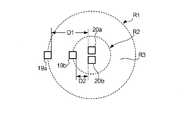
図8は、緑色光Lgの観測領域R1と赤色光Lrの観測領域R2とを示す図である。緑色光Lgの観測領域R1は、第2の受光部20aを中心として第1の発光部19aを通る円状の領域である。緑色光Lrの観測領域R2は、第2の発光部19bを中心として第2の発光部19bを通る円状の領域である。なお、図8では、観測領域R1及び観測領域R2は完全な円状の領域であるが、楕円状の領域であってもよい。上述したように、第1の発光部19aと第2の受光部20aとの間の距離D1は、第2の発光部19bと第2の受光部20bとの間の距離D2よりも大きい。したがって、緑色光Lgの観測領域R1は、赤色光Lrの観測領域R2よりも大きくなる。
FIG. 8 is a diagram showing an observation region R1 for green light Lg and an observation region R2 for red light Lr. The observation region R1 of the green light Lg is a circular region that passes through the first
緑色光Lgの観測領域R1には、赤色光Lrの観測領域R2と、観測領域R1と観測領域R2との差分である差分領域R3とが含まれる。この観測領域R2は、観測領域R1と観測領域R2との間で共通する領域である。この場合、赤色光Lrは、観測領域R2に存在する血管の脈動による影響を受けるのに対し、緑色光Lgは、観測領域R2に存在する血管の脈動による影響に加えて、差分領域R3に存在する血管の脈動による影響も受けることとなる。 The observation region R1 of the green light Lg includes an observation region R2 of the red light Lr and a difference region R3 that is a difference between the observation region R1 and the observation region R2. This observation region R2 is a common region between the observation region R1 and the observation region R2. In this case, the red light Lr is affected by the pulsation of the blood vessel existing in the observation region R2, while the green light Lg is present in the difference region R3 in addition to the influence of the blood vessel pulsation existing in the observation region R2. It will also be affected by the pulsation of the blood vessels.
図9は、反射板42及びスリット板43の作用を説明する図である。反射板42の開口部44は、観測領域R1と観測領域R2との共通する領域(観測領域R2)の一部である測定領域R4と対向する。第1の発光部19aから照射された緑色光Lgは、生体内の観測領域R1で反射される。このうち、測定領域R4で反射された緑色光Lgは、スリット板43のスリット45を通過して反射板42内に入射する。一方、測定領域R4以外の領域で反射された緑色光Lgは、開口部44に入らずに反射板42の外に到達するか、開口部44に設けられたスリット板43により遮られるため、反射板42内に入射しない。つまり、開口部44は、観測領域R1と観測領域R2との共通する領域の少なくとも一部で反射された緑色光Lgを受け入れる。スリット板43は、測定領域R4で反射された緑色光Lgはスリット45を介して通過させ、測定領域R4以外の領域で反射された緑色光Lgは遮断する。
FIG. 9 is a diagram for explaining the operation of the reflecting
同様に、第2の発光部19bから照射された赤色光Lrは、観測領域R2で反射される。このうち、反射板42と対向する測定領域R4で反射された赤色光Lgは、スリット板43のスリット45を通過して反射板42内に入射する。一方、測定領域R4以外の領域で反射された赤色光Lgは、開口部44に入らずに反射板42の外に到達するか、開口部44に設けられたスリット板43により遮られるため、反射板42内に入射しない。つまり、開口部44は、観測領域R1と観測領域R2との共通する領域の少なくとも一部で反射された赤色光Lrを受け入れる。スリット板43は、測定領域R4で反射された赤色光Lrはスリット45を介して通過させ、測定領域R4以外の領域で反射された赤色光Lrは遮断する。
Similarly, the red light Lr emitted from the second
反射板42内に入射した緑色光Lg及び赤色光Lrは、反射板42の反射面により反射され第1の受光面22a及び第2の受光面22bに集光される。この場合、第1の受光面22aには、第1の発光部19aから照射された緑色光Lgのうち、測定領域R4で反射された緑色光Lgだけが到達する。また、第2の受光面22bには、第2の発光部19bから照射された赤色光Lrのうち、測定領域R4で反射された赤色光Lrだけが到達する。
The green light Lg and the red light Lr incident on the reflecting
上述した実施形態によれば、生体内の同じ測定領域R4で反射された緑色光Lg及び赤色光Lrを用いて脈波を測定することができる。なお、この「同じ領域」とは、完全に一致する領域である必要はなく、同じとみなせる一定の範囲の領域であってもよい。また、上述した実施形態では、緑色光Lg及び赤色光Lrを集光しているため、第1の受光部20a及び第2の受光部20bから出力される信号の強度が大きくなる。したがって、例えば第1の発光部19a及び第2の発光部19bの光の照射強度を小さくして、省電力化を図ることができる。或いは、第1の受光面22a及び第2の受光面22bを小さくして、装置の小型化を図ることができる。
According to the embodiment described above, the pulse wave can be measured using the green light Lg and the red light Lr reflected by the same measurement region R4 in the living body. Note that the “same area” does not have to be a completely coincident area, and may be an area within a certain range that can be regarded as the same. In the above-described embodiment, since the green light Lg and the red light Lr are condensed, the intensity of the signals output from the first
また、上述した実施形態では、反射板42がドーム状の形状をしているため、緑色光Lg及び赤色光Lrを効率よく集光することができる。また、スリット板43は、複数のスリット45を有し、且つ、各スリット45の面積が大きいため、スリット45を通過する光量の減少を抑制することができる。
In the embodiment described above, since the reflecting
本発明は上述した実施形態に限定されず、以下のように変形してもよい。また、以下の変形例を相互に組み合わせてもよい。 The present invention is not limited to the above-described embodiment, and may be modified as follows. Further, the following modifications may be combined with each other.
(1)変形例1
スリット板43の構造は、図5に示すものに限定されない。例えば、複数のスリット45は、互いに斜めに配列されていてもよい。また、複数のスリット45は、放射線状に配列されていてもよい。また、以下のように、スリット45の数や形状を変えてもよい。
(1)
The structure of the
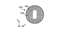
図10は、この変形例に係るスリット板43Aの上面図である。このスリット板43Aは、四角形の複数のスリット45Aを有する。この複数のスリット45Aは、図10に示すx軸方向及びy軸方向に沿ってマトリクス状に配列されている。つまり、複数のスリット45Aは、スリット板43Aの面に沿って2次元配列されている。また、スリット板43Aの中央部には、孔46Aが設けられている。第1の受光部20aと第2の受光部20bは、この孔46Aの中に設けられる。このスリット板43Aは、多数のスリット45Aを有しているため、スリット45Aを通過する光量の減少を抑制することができる。
FIG. 10 is a top view of the
図11は、この変形例に係るスリット板43Bの上面図である。このスリット板43Aは、円形の複数のスリット45Bを有する。この複数のスリット45Bは、スリット板43Bの面に沿って2次元配列されている。また、スリット板43Aの中央部には、上述したスリット板43と同様に、孔46Bが設けられている。第1の受光部20aと第2の受光部20bは、この孔46Bの中に設けられる。このスリット板43Bは、多数のスリット45Bを有しているため、スリット45Bを通過する光量の減少を抑制することができる。
FIG. 11 is a top view of a
(2)変形例2
スリット板43は、必ずしも設けられていなくてもよい。この場合、開口部44は、測定領域R4とその周辺の領域で反射された緑色光Lg及び赤色光Lrを受け入れることになる。ただし、この測定領域R4とその周辺の領域は、観測領域R1と観測領域R2との共通する領域(観測領域R2)の少なくとも一部である。そのため、このような構成であっても、生体内の同じ領域で反射された緑色光Lg及び赤色光Lrを用いて脈波を測定することができる。なお、上述した実施形態では、観測領域R2の全体が観測領域R1の中に含まれていたが、第1の受光部20a及び第2の受光部20bの位置によっては、観測領域R2の一部だけが観測領域R1の中に含まれる場合もある。この場合、この観測領域R2の一部が、観測領域R1と観測領域R2との共通する領域となる。
(2) Modification 2
The
(3)変形例3
反射板42の形状は、ドーム状に限定されない。反射板42は、多面体の反射面を有する形状であってもよい。反射板42は、開口部44を有し、光を集光する構造を有するものであればよい。
(3)
The shape of the reflecting
(4)変形例4
第1の発光部19a、第2の発光部19bが照射する光は、緑色光、赤色光に限定されない。例えば、青色光、赤外光等、他の波長の光であってもよい。
(4)
The light emitted by the first
(5)変形例5
上移した実施形態では、緑色光を受光する第1の受光部20aと、赤色光を受光する第2の受光部20bとが別々に設けられていた。しかし、第1の受光部20a及び第2の受光部20bに代えて、2分割フォトダイオードが用いられてもよい。
(5)
In the embodiment which moved up, the 1st light-receiving
(6)変形例6
装置本体3と脈波センサー4とは、無線通信で接続されていてもよい。また、装置本体3と脈波センサー4とが一体に構成されてもよい。また、脈波センサー4が装着される部位は、指に限定されない。例えば、手の甲、手首、上腕、足の甲、耳朶等、生体の他の部位であってもよい。
(6)
The apparatus
(7)変形例7
CPU11において実行されるプログラムは、磁気テープ、磁気ディスク、フレキシブルディスク、光ディスク、光磁気ディスク、メモリーなどの記録媒体に記録した状態で提供され、脈波測定装置1にインストールされてもよい。また、このプログラムは、インターネット等の通信回線を介して脈波測定装置1にダウンロードされてもよい。
(7) Modification 7
The program executed in the
1…脈波測定装置、3…装置本体、4…脈波センサー、11…CPU、12…ROM、13…RAM、14…表示部、15…操作部、16…発振回路、17…計時回路、18…駆動回路、19a…第1の発光部、19b…第2の発光部、20a…第1の受光部、20b…第2の受光部、21a…第1の信号処理部、21b…第2の信号処理部、41…筐体、42…反射板、43…スリット板、44…開口部、45…スリット、46…孔
DESCRIPTION OF
Claims (8)
前記第1の領域と共通する領域を有する前記生体の第2の領域に、前記第1の光と波長の異なる第2の光を照射する第2の照射部と、
前記共通する領域の少なくとも一部で反射された前記第1の光及び前記第2の光を受け入れる開口部、および内壁面を有し、前記内壁面には前記開口部により受け入れられた前記第1の光及び前記第2の光を反射する反射板が設けられ、前記反射板により前記第1の光及び前記第2の光を集光する集光部と、
前記集光部により集光された前記第1の光を受光し、第1の信号に変換する第1の受光部と、
前記集光部により集光された前記第2の光を受光し、第2の信号に変換する第2の受光部と、
前記第1の信号及び第2の信号に基づいて、前記生体の脈波を検出する検出部と、
前記開口部に設けられ、前記共通する領域のうち前記開口部と対向する領域で反射された前記第1の光及び前記第2の光を通過させるスリットを有し、前記対向する領域以外の領域で反射された前記第1の光及び前記第2の光を遮断するスリット板と
を備えることを特徴とする脈波測定装置。 A first irradiation unit that irradiates the first region of the living body with the first light;
A second irradiation unit that irradiates a second region of the living body having a region common to the first region with a second light having a wavelength different from that of the first light;
There is an opening for receiving the first light and the second light reflected by at least a part of the common region, and an inner wall surface, and the inner wall surface receives the first light received by the opening. A reflecting plate that reflects the first light and the second light, and a condensing unit that condenses the first light and the second light by the reflecting plate,
A first light receiving unit that receives the first light collected by the light collecting unit and converts the first light into a first signal;
A second light receiving unit that receives the second light collected by the light collecting unit and converts the second light into a second signal;
A detection unit for detecting a pulse wave of the living body based on the first signal and the second signal;
An area other than the opposed area, having a slit that is provided in the opening and allows the first light and the second light reflected in the common area to be reflected by the area facing the opening. A pulse wave measuring device comprising: a slit plate that blocks the first light and the second light reflected by the light source.
ことを特徴とする請求項1に記載の脈波測定装置。 The pulse wave measuring device according to claim 1 , wherein the slit plate has a plurality of slits.
ことを特徴とする請求項2に記載の脈波測定装置。 The pulse wave measuring device according to claim 2 , wherein the plurality of slits are linear slits and are arranged along one direction of the surface of the slit plate.
ことを特徴とする請求項2に記載の脈波測定装置。 The pulse wave measuring device according to claim 2 , wherein the plurality of slits are rectangular or circular slits.
前記第1の領域と共通する領域を有する前記生体の第2の領域に、前記第1の光と波長の異なる第2の光を照射する第2の照射部と、
前記共通する領域の少なくとも一部で反射された前記第1の光及び前記第2の光を受け入れる開口部、および内壁面を有し、前記内壁面には前記開口部により受け入れられた前記第1の光及び前記第2の光を反射する反射板が設けられ、前記反射板により前記第1の光及び前記第2の光を集光する集光部と、
前記集光部により集光された前記第1の光を受光し、第1の信号に変換する第1の受光部と、
前記集光部により集光された前記第2の光を受光し、第2の信号に変換する第2の受光部と、
前記第1の信号及び第2の信号に基づいて、前記生体の脈波を検出する検出部と
を備え、
前記第1の光の波長は、前記第2の光の波長よりも短く、
前記第1の照射部と前記第1の受光部との間の距離は、前記第2の照射部と前記第2の受光部との間の第2の距離よりも長い
ことを特徴とする脈波測定装置。 A first irradiation unit that irradiates the first region of the living body with the first light;
A second irradiation unit that irradiates a second region of the living body having a region common to the first region with a second light having a wavelength different from that of the first light;
There is an opening for receiving the first light and the second light reflected by at least a part of the common region, and an inner wall surface, and the inner wall surface receives the first light received by the opening. A reflecting plate that reflects the first light and the second light, and a condensing unit that condenses the first light and the second light by the reflecting plate,
A first light receiving unit that receives the first light collected by the light collecting unit and converts the first light into a first signal;
A second light receiving unit that receives the second light collected by the light collecting unit and converts the second light into a second signal;
A detection unit that detects a pulse wave of the living body based on the first signal and the second signal, and
The wavelength of the first light is shorter than the wavelength of the second light,
The distance between the first irradiation unit and the first light receiving unit is longer than the second distance between the second irradiation unit and the second light receiving unit. Wave measuring device.
ことを特徴とする請求項1乃至5のいずれか一項に記載の脈波測定装置。 The pulse wave measuring device according to any one of claims 1 to 5, wherein the reflecting plate has a region overlapping the first light receiving unit and the second light receiving unit in plan view.
前記第1の領域と共通する領域を有する前記生体の第2の領域に、前記第1の光と波長の異なる第2の光を照射する第2の照射部と、
前記共通する領域の少なくとも一部で反射された前記第1の光及び前記第2の光を受け入れる開口部、および内壁面を有し、前記内壁面には前記開口部により受け入れられた前記第1の光及び前記第2の光を反射する反射板が設けられ、前記反射板により前記第1の光及び前記第2の光を集光する集光部と、
前記集光部により集光された前記第1の光を受光し、第1の信号に変換する第1の受光部と、
前記集光部により集光された前記第2の光を受光し、第2の信号に変換する第2の受光部と、
前記開口部に設けられ、前記共通する領域のうち前記開口部と対向する領域で反射された前記第1の光及び前記第2の光を通過させるスリットを有し、前記対向する領域以外の領域で反射された前記第1の光及び前記第2の光を遮断するスリット板と
を備えることを特徴とする検出装置。 A first irradiation unit that irradiates the first region of the living body with the first light;
A second irradiation unit that irradiates a second region of the living body having a region common to the first region with a second light having a wavelength different from that of the first light;
There is an opening for receiving the first light and the second light reflected by at least a part of the common region, and an inner wall surface, and the inner wall surface receives the first light received by the opening. A reflecting plate that reflects the first light and the second light, and a condensing unit that condenses the first light and the second light by the reflecting plate,
A first light receiving unit that receives the first light collected by the light collecting unit and converts the first light into a first signal;
A second light receiving unit that receives the second light collected by the light collecting unit and converts the second light into a second signal;
An area other than the opposed area, having a slit that is provided in the opening and allows the first light and the second light reflected in the common area to be reflected by the area facing the opening. And a slit plate that blocks the first light and the second light reflected by the detector.
前記第1の領域と共通する領域を有する前記生体の第2の領域に、前記第1の光と波長の異なる第2の光を照射する第2の照射部と、
前記共通する領域の少なくとも一部で反射された前記第1の光及び前記第2の光を受け入れる開口部、および内壁面を有し、前記内壁面には前記開口部により受け入れられた前記第1の光及び前記第2の光を反射する反射板が設けられ、前記反射板により前記第1の光及び前記第2の光を集光する集光部と、
前記集光部により集光された前記第1の光を受光し、第1の信号に変換する第1の受光部と、
前記集光部により集光された前記第2の光を受光し、第2の信号に変換する第2の受光部と、
前記第1の信号及び第2の信号に基づいて、前記生体の脈波を検出する検出部と
を備え、
前記第1の光の波長は、前記第2の光の波長よりも短く、
前記第1の照射部と前記第1の受光部との間の距離は、前記第2の照射部と前記第2の受光部との間の第2の距離よりも長い
ことを特徴とする検出装置。 A first irradiation unit that irradiates the first region of the living body with the first light;
A second irradiation unit that irradiates a second region of the living body having a region common to the first region with a second light having a wavelength different from that of the first light;
There is an opening for receiving the first light and the second light reflected by at least a part of the common region, and an inner wall surface, and the inner wall surface receives the first light received by the opening. A reflecting plate that reflects the first light and the second light, and a condensing unit that condenses the first light and the second light by the reflecting plate,
A first light receiving unit that receives the first light collected by the light collecting unit and converts the first light into a first signal;
A second light receiving unit that receives the second light collected by the light collecting unit and converts the second light into a second signal;
A detection unit that detects a pulse wave of the living body based on the first signal and the second signal, and
The wavelength of the first light is shorter than the wavelength of the second light,
The distance between the first irradiation unit and the first light receiving unit is longer than the second distance between the second irradiation unit and the second light receiving unit. apparatus.
Priority Applications (1)
| Application Number | Priority Date | Filing Date | Title |
|---|---|---|---|
| JP2012015262A JP6179065B2 (en) | 2012-01-27 | 2012-01-27 | Pulse wave measurement device and detection device |
Applications Claiming Priority (1)
| Application Number | Priority Date | Filing Date | Title |
|---|---|---|---|
| JP2012015262A JP6179065B2 (en) | 2012-01-27 | 2012-01-27 | Pulse wave measurement device and detection device |
Publications (3)
| Publication Number | Publication Date |
|---|---|
| JP2013153845A JP2013153845A (en) | 2013-08-15 |
| JP2013153845A5 JP2013153845A5 (en) | 2015-03-12 |
| JP6179065B2 true JP6179065B2 (en) | 2017-08-16 |
Family
ID=49049667
Family Applications (1)
| Application Number | Title | Priority Date | Filing Date |
|---|---|---|---|
| JP2012015262A Active JP6179065B2 (en) | 2012-01-27 | 2012-01-27 | Pulse wave measurement device and detection device |
Country Status (1)
| Country | Link |
|---|---|
| JP (1) | JP6179065B2 (en) |
Families Citing this family (8)
| Publication number | Priority date | Publication date | Assignee | Title |
|---|---|---|---|---|
| US20160113529A1 (en) | 2014-10-23 | 2016-04-28 | Samsung Electronics Co., Ltd. | Blood pressure measuring apparatus, wrist watch type terminal having the same, and method of measuring blood pressure |
| JP6502718B2 (en) * | 2015-03-26 | 2019-04-17 | ローム株式会社 | Biometric information sensor |
| KR102656806B1 (en) * | 2016-04-28 | 2024-04-12 | 엘지전자 주식회사 | Watch type terminal and method of contolling the same |
| DE102016109694A1 (en) * | 2016-05-25 | 2017-11-30 | Osram Opto Semiconductors Gmbh | SENSOR DEVICE |
| JP6988802B2 (en) * | 2016-07-01 | 2022-01-05 | ソニーグループ株式会社 | Information processing equipment, information processing methods and programs |
| JP2017140439A (en) * | 2017-04-12 | 2017-08-17 | セイコーエプソン株式会社 | Pulse wave measuring module and electronic device |
| JPWO2021149426A1 (en) * | 2020-01-20 | 2021-07-29 | ||
| WO2023058550A1 (en) * | 2021-10-05 | 2023-04-13 | 株式会社村田製作所 | Sensing device and device set |
Family Cites Families (10)
| Publication number | Priority date | Publication date | Assignee | Title |
|---|---|---|---|---|
| JP3790030B2 (en) * | 1997-10-30 | 2006-06-28 | コーリンメディカルテクノロジー株式会社 | Reflective photoelectric pulse wave detector |
| JP3651442B2 (en) * | 2001-02-02 | 2005-05-25 | 日本電信電話株式会社 | Blood flow meter and blood flow sensor |
| JP4182987B2 (en) * | 2006-04-28 | 2008-11-19 | 日本電気株式会社 | Image reading device |
| JP2008237686A (en) * | 2007-03-28 | 2008-10-09 | Sanyo Electric Co Ltd | Extensible sensor and physical condition management apparatus |
| JP4831111B2 (en) * | 2008-04-22 | 2011-12-07 | 日本光電工業株式会社 | Signal processing method and pulse photometer using the same |
| WO2009139029A1 (en) * | 2008-05-12 | 2009-11-19 | パイオニア株式会社 | Self-luminous sensor device and method for manufacturing the same |
| JP5332713B2 (en) * | 2009-02-24 | 2013-11-06 | セイコーエプソン株式会社 | Optical sensor and measurement system |
| JP2011104124A (en) * | 2009-11-17 | 2011-06-02 | Seiko Epson Corp | Pulse measuring apparatus |
| JP5581697B2 (en) * | 2010-01-05 | 2014-09-03 | セイコーエプソン株式会社 | Biological information detector and biological information measuring device |
| JP5742104B2 (en) * | 2010-03-25 | 2015-07-01 | セイコーエプソン株式会社 | Optical device and biological information detector |
-
2012
- 2012-01-27 JP JP2012015262A patent/JP6179065B2/en active Active
Also Published As
| Publication number | Publication date |
|---|---|
| JP2013153845A (en) | 2013-08-15 |
Similar Documents
| Publication | Publication Date | Title |
|---|---|---|
| JP6179065B2 (en) | Pulse wave measurement device and detection device | |
| KR102203563B1 (en) | Systems and methods for measuring non-pulsatile blood volume | |
| JP3760920B2 (en) | Sensor | |
| EP2839778A1 (en) | Pulse wave measuring apparatus | |
| US11478158B2 (en) | Wearable ring of optical biometric sensors | |
| JP5056867B2 (en) | Biological information detection apparatus and biological information detection method | |
| JP4475601B2 (en) | Self-luminous sensor device and biological information detection method | |
| US10912469B2 (en) | Electronic fitness device with optical cardiac monitoring | |
| US20140343383A1 (en) | Measurement device, measurement method, program and recording medium | |
| KR20160088127A (en) | Apparatus for detecting information of the living body | |
| JP2007054497A (en) | Detector | |
| WO2015151587A1 (en) | Measurement device, measurement method, program, and recording medium | |
| US10244953B2 (en) | Biological information detecting device and electronic apparatus | |
| JP2011087657A (en) | Measuring apparatus and measuring method | |
| US10201287B2 (en) | Biological information detecting device and electronic apparatus | |
| CN106999117B (en) | Pulse oximetry device and method for operating a pulse oximetry device | |
| JP3790030B2 (en) | Reflective photoelectric pulse wave detector | |
| JP2005052385A (en) | Biological information measuring device | |
| JP2013000540A (en) | Pulse wave detector, and pulse wave detection system | |
| CN109152543A (en) | sensor device | |
| WO2013073244A1 (en) | Biometric device, biometric method, program, and recording medium | |
| KR20150098940A (en) | Physiological Signal Sensing Device | |
| WO2017061204A1 (en) | Blood pressure measurement device | |
| US20150265154A1 (en) | Systems and methods for a multi-element medical sensor | |
| US20220240858A1 (en) | Apparatus for measuring optical or physiological parameters in scattering media featuring an optical contact detector |
Legal Events
| Date | Code | Title | Description |
|---|---|---|---|
| A521 | Written amendment |
Free format text: JAPANESE INTERMEDIATE CODE: A523 Effective date: 20150122 |
|
| A621 | Written request for application examination |
Free format text: JAPANESE INTERMEDIATE CODE: A621 Effective date: 20150122 |
|
| A977 | Report on retrieval |
Free format text: JAPANESE INTERMEDIATE CODE: A971007 Effective date: 20151007 |
|
| A131 | Notification of reasons for refusal |
Free format text: JAPANESE INTERMEDIATE CODE: A131 Effective date: 20151201 |
|
| A521 | Written amendment |
Free format text: JAPANESE INTERMEDIATE CODE: A523 Effective date: 20160129 |
|
| A131 | Notification of reasons for refusal |
Free format text: JAPANESE INTERMEDIATE CODE: A131 Effective date: 20160705 |
|
| A521 | Written amendment |
Free format text: JAPANESE INTERMEDIATE CODE: A523 Effective date: 20160819 |
|
| A131 | Notification of reasons for refusal |
Free format text: JAPANESE INTERMEDIATE CODE: A131 Effective date: 20170131 |
|
| A521 | Written amendment |
Free format text: JAPANESE INTERMEDIATE CODE: A523 Effective date: 20170222 |
|
| TRDD | Decision of grant or rejection written | ||
| A01 | Written decision to grant a patent or to grant a registration (utility model) |
Free format text: JAPANESE INTERMEDIATE CODE: A01 Effective date: 20170620 |
|
| A61 | First payment of annual fees (during grant procedure) |
Free format text: JAPANESE INTERMEDIATE CODE: A61 Effective date: 20170703 |
|
| R150 | Certificate of patent or registration of utility model |
Ref document number: 6179065 Country of ref document: JP Free format text: JAPANESE INTERMEDIATE CODE: R150 |