JP6175439B2 - Apparatus and method for the production of trisilylamine by concentrated phase - Google Patents
Apparatus and method for the production of trisilylamine by concentrated phase Download PDFInfo
- Publication number
- JP6175439B2 JP6175439B2 JP2014534723A JP2014534723A JP6175439B2 JP 6175439 B2 JP6175439 B2 JP 6175439B2 JP 2014534723 A JP2014534723 A JP 2014534723A JP 2014534723 A JP2014534723 A JP 2014534723A JP 6175439 B2 JP6175439 B2 JP 6175439B2
- Authority
- JP
- Japan
- Prior art keywords
- solvent
- reaction
- temperature
- tsa
- ammonia
- Prior art date
- Legal status (The legal status is an assumption and is not a legal conclusion. Google has not performed a legal analysis and makes no representation as to the accuracy of the status listed.)
- Active
Links
Images


Classifications
-
- C—CHEMISTRY; METALLURGY
- C01—INORGANIC CHEMISTRY
- C01B—NON-METALLIC ELEMENTS; COMPOUNDS THEREOF; METALLOIDS OR COMPOUNDS THEREOF NOT COVERED BY SUBCLASS C01C
- C01B21/00—Nitrogen; Compounds thereof
- C01B21/082—Compounds containing nitrogen and non-metals and optionally metals
- C01B21/087—Compounds containing nitrogen and non-metals and optionally metals containing one or more hydrogen atoms
Description
本発明は、溶媒中でのシリルアミン、特にトリシリルアミンを合成するバッチ法に関する。本発明は、シリルアミンを高効率で合成するのに適した反応条件を実現するプロセスに関する。対象となる主要なシリルアミンはトリシリルアミンである。商業的規模の量でのジシリルアミンの製造も本発明の範囲内である。 The present invention relates to a batch process for synthesizing silylamines, particularly trisilylamines, in a solvent. The present invention relates to a process for realizing reaction conditions suitable for synthesizing silylamine with high efficiency. The primary silylamine of interest is trisilylamine. The production of disilylamine in commercial scale quantities is also within the scope of the present invention.
トリシリルアミン(「TSA」)は半導体の製造に有用な分子である。トリシリルアミンは、一旦製造されると安定であるが、過剰な反応条件下では分解し、副産物を生成しやすい。特許文献1において、基板の入ったCVD反応チャンバーにトリシリルアミンとアンモニアとを供給することにより、この基板上に安定な窒化シリコン膜が形成されることが実証されている。 Trisilylamine (“TSA”) is a useful molecule for semiconductor manufacturing. Trisilylamine is stable once manufactured, but tends to decompose and generate by-products under excessive reaction conditions. In Patent Document 1, it is demonstrated that a stable silicon nitride film is formed on a substrate by supplying trisilylamine and ammonia to a CVD reaction chamber containing the substrate.
非特許文献1において、塩化シリルとアンモニアとの反応により、トリシリルアミンを調製するバッチ法についての論考がなされている。非特許文献1には、トリシリルアミンの収率が、混合方法及び反応物の純度によって変化したとの報告がある。それによると、塩化シリルの入った1リットルのバルブ(bulb)へと下方からアンモニアを導入することにより、反応物をガス相において混合した。非常にゆっくりとガス状のアンモニアを導入した後、反応バルブとその内容物は15分間室温のまま保持された。混合を行うとすぐに多量の白い固体がバルブの壁面に析出した。生成物は取り除かれ、トリシリルアミンが回収された。このプロセスの収率は、理論量のトリシリルアミンに対して約77%であった。 Non-Patent Document 1 discusses a batch method for preparing trisilylamine by a reaction between silyl chloride and ammonia. Non-Patent Document 1 reports that the yield of trisilylamine changed depending on the mixing method and the purity of the reaction product. According to it, the reactants were mixed in the gas phase by introducing ammonia from below into a 1 liter bulb containing silyl chloride. After introducing gaseous ammonia very slowly, the reaction valve and its contents were kept at room temperature for 15 minutes. Immediately after mixing, a large amount of white solid was deposited on the wall of the bulb. The product was removed and trisilylamine was recovered. The yield of this process was about 77% based on the theoretical amount of trisilylamine.
このバッチ反応プロセスでは、モノハロシランの全量を反応容器に入れる。バッチサイズは、この初期投入量と上記容器のサイズによって制限される。その後、アンモニアガスをゆっくりとフラスコへと添加する。モノハロシラン及びアンモニアの初期濃度並びに容器中での乱流混合効率(efficiency of turbulent mixing)によって、容器内での反応条件を変化させる。混合は、容器のサイズ、及びもし採用するのであれば機械混合装置の効率の影響を受ける。加えて、バッチプロセス中、生成したシリルアミンは、同じく反応の生成物であるハロゲン化アンモニウムと接触する。塩化アンモニウム等のハロゲン化アンモニウムは触媒であり、TSAをシラン及び他の分解生成物へと不均化させてしまい、TSAの収率を低下させる。ハロゲン化シリルとアンモニアの反応は熱を生成し、これにより閉鎖系反応容器における分解条件が悪化する。 In this batch reaction process, the entire amount of monohalosilane is placed in a reaction vessel. The batch size is limited by this initial charge and the size of the container. Thereafter, ammonia gas is slowly added to the flask. Depending on the initial concentration of monohalosilane and ammonia and the efficiency of turbulent mixing in the vessel, the reaction conditions in the vessel are varied. Mixing is affected by the size of the container and, if employed, the efficiency of the mechanical mixing device. In addition, during the batch process, the silylamine produced is contacted with ammonium halide, which is also the product of the reaction. Ammonium halides such as ammonium chloride are catalysts and disproportionate TSA into silane and other decomposition products, reducing the yield of TSA. The reaction between the silyl halide and ammonia generates heat, which degrades the decomposition conditions in the closed reaction vessel.
特許文献2は、シリルアミンを合成するための管状のガス相流反応器(tubular flow gas phase reactor)及びプロセスに関するものであり、高い収量効率で大量のシリルアミンを製造することが見出されている。この反応器は、栓流装置と層流装置に見られる特性を兼ね備えている。この特性の組合せにより、大量かつ高効率でシリルアミンが合成される。対象となる主要なシリルアミンはトリシリルアミンである。商業的規模の量でのジシリルアミンの製造もこの発明の範囲内である。このプロセスは、ハロゲン化アンモニウムを大量に生成するので、各製造バッチを行うごとに反応管を開放し、清掃を行う必要がある。これは、非常に面倒なプロセスであり、かなりの時間の休止につながる。 U.S. Patent No. 6,057,031 relates to a tubular flow gas phase reactor and process for synthesizing silylamine and has been found to produce large quantities of silylamine with high yield efficiency. This reactor combines the characteristics found in plug flow devices and laminar flow devices. Due to this combination of properties, silylamine is synthesized in large quantities and with high efficiency. The primary silylamine of interest is trisilylamine. Production of disilylamine in commercial scale quantities is also within the scope of this invention. Since this process produces a large amount of ammonium halide, it is necessary to open the reaction tube and clean each production batch. This is a very tedious process and leads to a considerable time pause.
本発明は、TSAを合成する濃縮相バッチプロセスであって、(a)反応容器に溶媒を添加すること、(b)その溶媒を冷却すること、(c)その溶媒中でモノハロシランを濃縮して溶液を形成すること、(d)その溶液に無水アンモニアを添加して反応混合物を形成すること、(e)その反応混合物から、シリルアミン、過剰量のモノハロシラン及びTSAを分離すること、及び(f)そのシリルアミンを精製してTSAを得ることを含む、プロセスに関する。 The present invention is a concentrated phase batch process for synthesizing TSA comprising: (a) adding a solvent to a reaction vessel; (b) cooling the solvent; (c) concentrating a monohalosilane in the solvent. Forming a solution; (d) adding anhydrous ammonia to the solution to form a reaction mixture; (e) separating silylamine, excess monohalosilane and TSA from the reaction mixture; and (f). It relates to a process comprising purifying the silylamine to obtain TSA.
過剰量のモノクロロシラン(「MCS」)等のモノハロシランと、アンモニアとの濃縮相反応は、MCSの場合には塩化アンモニウム(「NH4Cl」)塩であるハロゲン化アンモニウム塩を同時に製造しながら、TSAの生成が迅速に行われることから有益である。この塩は、溶媒と共にスラリーとして反応ゾーンに局在化している。この手法では、塩化アンモニウム塩が分散する熱伝達媒体として働く高沸点溶媒を用いるのが好ましく、下流で生成物を取り除く際に塩の生成が避けられる。この手法の一般的な利点は、濃縮相にTSAを生成した後、反応スラリーからこの生成物を真空ストリッピングし、不要な塩/溶媒スラリーを反応容器から排出することにあり、その後、別のバッチ合成に備えて、反応器に溶媒、及び過剰量の液化モノハロシランを入れることができる。この濃縮相プロセスにおいては、反応の副産物である塩化アンモニウム塩が溶媒中のスラリーとして除去されるので、反応器を次のバッチ運転の前に清掃する必要がない。 The concentrated phase reaction of an excess of monohalosilane, such as monochlorosilane (“MCS”), with ammonia, in the case of MCS, simultaneously produces an ammonium halide salt, which is an ammonium chloride (“NH 4 Cl”) salt, This is beneficial because TSA generation is rapid. This salt is localized in the reaction zone as a slurry with the solvent. In this approach, it is preferable to use a high boiling point solvent that acts as a heat transfer medium in which the ammonium chloride salt is dispersed, so that salt formation is avoided when removing the product downstream. The general advantage of this approach is that after producing TSA in the concentrated phase, the product is vacuum stripped from the reaction slurry and the unwanted salt / solvent slurry is drained from the reaction vessel before another In preparation for batch synthesis, the reactor can be charged with solvent and an excess of liquefied monohalosilane. In this concentrated phase process, the ammonium chloride salt, a by-product of the reaction, is removed as a slurry in the solvent so that the reactor does not need to be cleaned before the next batch run.
この濃縮相反応スキームは以下の利点を有する。
A 溶媒中におけるアンモニアとモノハロシランとの低温濃縮相反応により、比較的短時間にTSAの生成が促進される。
B アニソール(メトキシベンゼン)等の適切な溶媒により、MCS試薬の蒸気圧降下//沸点上昇がもたらされ、これにより液化MCSの形成及び濃縮相における好適な中間生成物であるジシリルアミン(「DSA」)の反応速度を促進する。
C 溶媒が、反応混合物において、副産物である不要な塩の大部分を分散し局在化させる均一な熱伝達媒体として働く。
D 生成物の収集において、さらに下流で反応し得る部分置換シリルアミン(DSA等)を抑制する。
This concentrated phase reaction scheme has the following advantages.
A The low-temperature concentrated phase reaction between ammonia and monohalosilane in the solvent accelerates the production of TSA in a relatively short time.
B A suitable solvent such as anisole (methoxybenzene) results in a drop in vapor pressure // boiling point of the MCS reagent, thereby forming a liquified MCS and a suitable intermediate product disilylamine (“DSA”) in the concentrated phase. ) To accelerate the reaction rate.
The C solvent acts as a uniform heat transfer medium in the reaction mixture to disperse and localize most of the unwanted salts that are by-products.
D In the product collection, partially substituted silylamines (DSA, etc.) that can react further downstream are suppressed.
完全な反応は、
4NH3+3SiH3X→3NH4X+(SiH3)3N
である。
The complete reaction is
4NH 3 + 3SiH 3 X → 3NH 4 X + (SiH 3 ) 3 N
It is.
本発明のシリルアミンは、下記の反応順序に従って製造されると考えられる。
2NH3+SiH3X→NH4X+SiH3NH2
2SiH3NH2→NH3+(SiH3)2NH
3(SiH3)2NH→NH3+2(SiH3)3N
式中、Xは、Cl、F、Br、Iである。
The silylamine of the present invention is considered to be produced according to the following reaction sequence.
2NH 3 + SiH 3 X → NH 4 X + SiH 3 NH 2
2SiH 3 NH 2 → NH 3 + (SiH 3 ) 2 NH
3 (SiH 3 ) 2 NH → NH 3 +2 (SiH 3 ) 3 N
In the formula, X is Cl, F, Br, or I.
以下、添付の図面を参照して、本発明の実施形態を詳細に説明する。 Hereinafter, embodiments of the present invention will be described in detail with reference to the accompanying drawings.
本発明の方法は、一般的には、以下を含む:
反応器に適切な溶媒(アニソール、高沸点エーテル、脂肪族炭化水素及び芳香族炭化水素等)を入れること;
溶媒又は溶媒混合物(1つ又は複数の溶媒)を100℃〜−78℃の温度範囲に調節すること;
(系中に添加されるアンモニアの最終量に対して)約5モル%〜約300モル%の範囲で過剰量のモノハロシランを濃縮すること;
ポリシラザン及びシランの生成、ならびに溶媒と反応物が反応することによる不要物の生成のいずれも引き起こすことがないような速度で、液面より下の位置にある1つ又は複数の浸漬管/スパージ管を通して、前記溶液に無水アンモニアを添加すること;(前記溶液にアンモニアを添加する速度に影響する因子としては、特に限定されないが、溶媒の体積、モノハロシランの濃度、溶媒反応混合物の温度、混合効率及び反応容器からの熱伝達速度が挙げられる。中規模のバッチ反応におけるアンモニアの好ましい添加速度は、約100mg/分〜5g/分である。より大規模な製造バッチでは、この添加速度はバッチサイズに応じたものであり、そのためサイズに比例して大きくなると考えられる。アンモニアの添加の際の反応溶媒の温度は、約70℃から、溶媒及び反応物溶液の凝固点をちょうど上回る温度であることが好ましい。)
反応溶液から反応生成物を分離すること;(好ましい分離方法としては、生成物混合物の真空ストリッピング又は蒸留が挙げられる。これらの分離方法は、アンモニアの全量を一度に添加した後、減圧下で濾過を行い、生成物(複数の場合もあり)を含む留出物を低温度のクライオトラップ(cryotrap)を用いて捕集することにより行ってもよい。反応混合物の温度が、真空ストリッピング中に上昇してもよい。パイロットスケールのバッチでは、真空ストリッピング中に、反応混合物の温度は約100℃まで上昇した。)
生成物を精製して純粋なアミノシランを得ること;(好ましいアミノシランはTSAである。好ましい精製プロセスは分留又は蒸留である。)及び
不要な塩化アンモニウム塩を溶媒中に混合して、該溶媒中に固体を懸濁又はスラリー化し、ドレーン又は圧力によってこの不要ストリームを反応器から移動させること(上記反応器は、別のバッチ合成のために再充填することができる)。
The method of the present invention generally includes the following:
Placing a suitable solvent (such as anisole, high-boiling ethers, aliphatic hydrocarbons and aromatic hydrocarbons) into the reactor;
Adjusting the solvent or solvent mixture (s) to a temperature range of 100 ° C to -78 ° C;
Concentrating excess monohalosilane in the range of about 5 mol% to about 300 mol% (relative to the final amount of ammonia added into the system);
One or more dip tubes / sparge tubes located below the liquid level at a rate that does not cause the formation of polysilazane and silane, and the formation of unwanted matter due to reaction of the solvent with the reactants Adding anhydrous ammonia to the solution through; (factors affecting the rate at which ammonia is added to the solution are not particularly limited, but include the volume of the solvent, the concentration of the monohalosilane, the temperature of the solvent reaction mixture, the mixing efficiency and The rate of heat transfer from the reaction vessel is the preferred rate of addition of ammonia in the medium scale batch reaction is about 100 mg / min to 5 g / min, and for larger production batches this rate is dependent on the batch size. The reaction solvent temperature during the addition of ammonia is considered to increase in proportion to the size. From about 70 ° C., it is preferred the freezing point of the solvent and the reaction product solution is just above the temperature.)
Separating the reaction product from the reaction solution; (preferred separation methods include vacuum stripping or distillation of the product mixture. These separation methods can be carried out under reduced pressure after all of the ammonia has been added all at once. Filtration and distillate containing product (s) may be collected using a low temperature cryotrap, where the temperature of the reaction mixture is during vacuum stripping. (In pilot scale batches, the temperature of the reaction mixture increased to about 100 ° C. during vacuum stripping.)
Purify the product to obtain pure aminosilane; (The preferred aminosilane is TSA. The preferred purification process is fractional distillation or distillation) and the unwanted ammonium chloride salt is mixed in the solvent The solid is suspended or slurried in, and this unwanted stream is removed from the reactor by drain or pressure (the reactor can be recharged for another batch synthesis).
好ましい実施形態においては、アニソールが溶媒であり、アンモニアに対して約20モル%〜約50モル%過剰量のモノハロシランを用い、反応温度は約10℃〜約60℃である。好ましい実施形態においては、上記モノハロシランはMCSである。 In a preferred embodiment, anisole is the solvent, with a monohalosilane excess of about 20 mol% to about 50 mol% relative to ammonia, and the reaction temperature is about 10 ° C. to about 60 ° C. In a preferred embodiment, the monohalosilane is MCS.
アンモニアの好ましい添加プロセスは、溶液中でアンモニアとMCSとを反応させ、溶液より上のヘッドスペースにおいてあらゆる気相反応を制限することである。これにより、反応容器の露出面上及び低温トラップ(cryogenic trap)等の反応容器の下流において、塩化アンモニウムが増大するのを避けることができる。下流の貯蔵容器中に含まれる塩化アンモニウム塩を「下流塩」と称する。 The preferred process of adding ammonia is to react ammonia and MCS in solution and limit any gas phase reaction in the headspace above the solution. This avoids an increase in ammonium chloride on the exposed surface of the reaction vessel and downstream of the reaction vessel such as a cryogenic trap. The ammonium chloride salt contained in the downstream storage container is referred to as “downstream salt”.
溶媒アスペクト比は、溶媒(液面)の高さを反応器の内径で除したものであると定義され、アンモニア又は中間生成物のジシリルアミン(DSA)が、溶媒とヘッドスペースとの界面で、液体表面を突破しなければならない経路に関して重要である。 The solvent aspect ratio is defined as the height of the solvent (liquid level) divided by the inner diameter of the reactor, where ammonia or the intermediate product disilylamine (DSA) is liquid at the interface between the solvent and the headspace. It is important with respect to the path that has to break through the surface.
上記アスペクト比の下限値は、重要なものではないが、特定の反応器において、溶媒、MCS濃度、温度及び圧力等のパラメーターを考慮しつつ、無水アンモニアのガス流速/供給速度を設定するための、経験に基づいた指針とする。 The lower limit of the aspect ratio is not important, but for setting the gas flow rate / feed rate of anhydrous ammonia in a specific reactor while taking into account parameters such as solvent, MCS concentration, temperature and pressure. The guideline is based on experience.
反応器の好ましい操作は、アンモニアの全量が溶液中でMCSと反応し、溶液を脱出して溶媒表面より上のヘッドスペースへと入るアンモニアガスがないように、アンモニアガスの供給速度を調節することで達成される。より良いガス分散方法、より良い混合、より高い溶媒アスペクト比により、アンモニアガスの流速をより高くすることができ、これにより処理時間を速くすることができる。 The preferred operation of the reactor is to adjust the ammonia gas feed rate so that the total amount of ammonia reacts with MCS in the solution and no ammonia gas escapes the solution and enters the headspace above the solvent surface. To be achieved. Better gas dispersion methods, better mixing, and higher solvent aspect ratios can result in higher ammonia gas flow rates, which can increase processing time.
上記プロセスの好ましい温度範囲は、約−55℃〜約60℃である。一般的に、反応プロセスの操作温度の下限値は溶媒中におけるMCSの融点であり、温度上限値は生成物の分解及びプロセスの効率の低下を避けるため等といった作業条件に従って決定される。アニソールの場合、添加されるMCSの量によって、アニソールの融点である−37.3℃未満に大きく融点が降下する。特定の溶媒中での所定濃度のMCSの融点は、当業者によって過度の実験を行うことなく容易に決定される。 A preferred temperature range for the process is from about -55 ° C to about 60 ° C. In general, the lower limit of the reaction process operating temperature is the melting point of MCS in the solvent, and the upper temperature limit is determined according to operating conditions such as to avoid degradation of the product and a decrease in process efficiency. In the case of anisole, the melting point greatly falls below -37.3 ° C. which is the melting point of anisole depending on the amount of MCS added. The melting point of a given concentration of MCS in a particular solvent is readily determined by one skilled in the art without undue experimentation.
本発明の溶媒は、熱輸送媒体及びTSAの生成中に形成される塩化アンモニウムを分散する媒体として作用する。この溶媒は、下記の性質を全て有していなければならない。
出発物質、中間生成物又は最終生成物と反応せず、かつ
蒸留物/生成物の最適な回収を可能にする沸点又は蒸気圧を有する。
The solvent of the present invention acts as a heat transport medium and a medium for dispersing ammonium chloride formed during the production of TSA. This solvent must have all of the following properties:
Has a boiling point or vapor pressure that does not react with the starting material, intermediate product or final product and allows for optimal recovery of the distillate / product.
所定の温度における溶媒の蒸気圧とTSAの蒸気圧との比は、溶媒からの反応生成物の真空ストリッピングを容易にする観点から、約1:5以下、好ましくは約1:10以下である。本明細書中、1:10の蒸気圧比は、1:5の蒸気圧比よりも小さいと見なされる。反対に、100:1の蒸気圧比は、10:1の蒸気圧比よりも大きいと見なされる。好ましい実施形態においては、上記溶媒はアニソールであり、約20℃〜約40℃の温度において、アニソールとTSAとの蒸気圧の比は3.5:315であり、これは約1:90に等しい。上記蒸気圧の比は、真空ストリッピング又は蒸留によって溶媒からTSA及びDSAを取り除く分離効率の重要な指標である。DSA及びTSAの蒸気圧に比して低い蒸気圧を有する溶媒を使用すると、反応溶媒からのDSA及びTSAの真空ストリッピング並びにDSA生成物及びTSA生成物の収集が容易になる。 The ratio of the vapor pressure of the solvent and the vapor pressure of TSA at a given temperature is about 1: 5 or less, preferably about 1:10 or less, from the viewpoint of facilitating vacuum stripping of the reaction product from the solvent. . In the present specification, a vapor pressure ratio of 1:10 is considered smaller than a vapor pressure ratio of 1: 5. Conversely, a vapor pressure ratio of 100: 1 is considered greater than a vapor pressure ratio of 10: 1. In a preferred embodiment, the solvent is anisole, and at a temperature of about 20 ° C. to about 40 ° C., the vapor pressure ratio of anisole to TSA is 3.5: 315, which is equal to about 1:90. . The vapor pressure ratio is an important indicator of the separation efficiency of removing TSA and DSA from the solvent by vacuum stripping or distillation. The use of a solvent having a vapor pressure lower than that of DSA and TSA facilitates the vacuum stripping of DSA and TSA from the reaction solvent and the collection of DSA and TSA products.
一方、DSA及びTSAの蒸気圧に比して高い蒸気圧を有する溶媒を使用すると、DSA及びTSAから溶媒を除去するのが容易になり、沸点が低く蒸気圧が高い上記溶媒は収集しない貯蔵容器内に、濃縮したDSA生成物及びTSA生成物が残る。その後、収集されたDSA生成物及びTSA生成物は、本明細書及び文献に開示されるような標準的な方法によって更に精製することができる。 On the other hand, when a solvent having a higher vapor pressure than that of DSA and TSA is used, it becomes easy to remove the solvent from DSA and TSA, and the storage container does not collect the solvent having a low boiling point and a high vapor pressure. Inside, concentrated DSA and TSA products remain. The collected DSA and TSA products can then be further purified by standard methods as disclosed herein and in the literature.
適切な溶媒としては、非プロトン性溶媒、非酸性(ルイス酸性)溶媒及び強い水素結合を形成しない溶媒(水素結合の元となるN−H)が挙げられる。溶媒は、高沸点一酸素含有エーテル(mono-oxygenated ethers)からなる群から選ばれることが好ましく、そのエーテルの例は、特に限定されないが、R−O−R’(式中、R及びR’は同一でも異なってもよく、直鎖状、分岐状又は環状のアルキル基を表す)である。本発明のプロセスにおいては、溶媒の混合物が適切である。好ましい溶媒の沸点ひいては蒸気圧は、TSAに比して高くても低くてもよい。実施例においては、TSAに対して少なくとも約1:10の蒸気圧比(溶媒:TSA)を有する溶媒が選ばれ、これにより溶媒の移動を殆ど行うことなく、TSAを容易に真空ストリップすることができた。例えば、25℃でTSAは315torrの蒸気圧を有し、アニソールは同温度で3.5torrの蒸気圧を有する。 Suitable solvents include aprotic solvents, non-acidic (Lewis acidic) solvents, and solvents that do not form strong hydrogen bonds (N—H that is the source of hydrogen bonding). The solvent is preferably selected from the group consisting of high-boiling mono-oxygenated ethers, and examples of the ether are not particularly limited, but include R—O—R ′ (wherein R and R ′ May be the same or different and each represents a linear, branched or cyclic alkyl group. In the process of the present invention, a mixture of solvents is suitable. The boiling point of the preferred solvent and thus the vapor pressure may be higher or lower than that of TSA. In the examples, a solvent having a vapor pressure ratio (solvent: TSA) of at least about 1:10 relative to TSA is selected, which allows the TSA to be easily vacuum stripped with little solvent transfer. It was. For example, at 25 ° C., TSA has a vapor pressure of 315 torr, and anisole has a vapor pressure of 3.5 torr at the same temperature.
実施例では、数種類の溶媒を使用した。好ましい溶媒はアニソールである。本発明において有用な溶媒としては、特に限定されないが、アニソール、m−キシレン、トルエン、オルト−キシレン;ジ−n−ブチルエーテル、ジ−t−ブチルエーテル、ジ−sec−ブチルエーテル、ジ−n−ヘキシルエーテル、メトキシベンゼン、ジオキサン(2つの酸素を含む環状エーテル)といった高沸点エーテルが挙げられる。上述のように、高揮発性のエーテルは、ジエチルエーテル及びテトラヒドロフランと同様の働きをすることができる。すなわち、後者のエーテルは、沸点及び蒸気圧が近いことから、TSAからの分離がより困難となる。高沸点エーテルがより好ましく、ヘプタン、デカン、スクワラン、スクワレン、シクロヘキサン、環状炭化水素及び縮合環式炭化水素等の脂肪族炭化水素、トルエン、(メタ−、オルト−)キシレン、0℃より低い融点を有する縮合芳香族化合物等の芳香族炭化水素が好ましい。溶媒の混合物も本発明の範囲内である。 In the examples, several types of solvents were used. A preferred solvent is anisole. Solvents useful in the present invention are not particularly limited, but include anisole, m-xylene, toluene, ortho-xylene; di-n-butyl ether, di-t-butyl ether, di-sec-butyl ether, di-n-hexyl ether. , Methoxybenzene, and dioxane (a cyclic ether containing two oxygens). As mentioned above, highly volatile ethers can act similarly to diethyl ether and tetrahydrofuran. That is, since the latter ether has a boiling point and a vapor pressure close to each other, separation from TSA becomes more difficult. High-boiling ethers are more preferred, aliphatic hydrocarbons such as heptane, decane, squalane, squalene, cyclohexane, cyclic hydrocarbons and condensed cyclic hydrocarbons, toluene, (meta-, ortho-) xylene, melting point lower than 0 ° C Aromatic hydrocarbons such as condensed aromatic compounds are preferred. Mixtures of solvents are also within the scope of the present invention.
実施例1
シュレンク管反応器を用いた合成(図1)
Example 1
Synthesis using Schlenk tube reactor (Figure 1)
内部熱電対プローブ15(外径1/8’’のステンレス鋼製、T型)、外径1/8’’のステンレス鋼製のアンモニアスパージ管18及び外径1/4’’のHDPE管類を備えた250mLのシュレンク管19に、窒素下で、100mLの無水アニソールを入れた。このシュレンク管を温度制御槽に入れた。スパージ管の端部を液面より上に上げ、溶媒を−35℃まで冷却した(アニソールの凝固点は−37℃である)。その後、マグネティックスターラーバー17で溶媒を撹拌しながら、ヘッドスペースの窒素を、真空下でシュレンク管から除去し、最終的な圧力を1torrより低くした。その後、上記反応管を閉じた状態で、圧力900torrのMCS(26.4g、397ミリモル)の入った7.8L(内部容積)の炭素鋼製シリンダー25を近接したU字トラップ(図示しない)へと(チューブ27を介して)濃縮した。そして、シュレンク管の上に位置する弁アダプター29(図1参照)を開き、U字トラップ中のMCSを周辺温度まで温め、反応管19へと濃縮した。この反応管を更に−60℃まで冷却し、内部圧力はおよそ63torrまで低下した(溶液を更に−65℃まで冷却すると、溶媒の凝固を引き起こした)。その後、反応管を−45℃まで温め、室内窒素(house nitrogen)流を数分間添加してスパージ管18からMCSを全て除去した(内部圧力は、この間に510torrまで上昇した)。アンモニアシリンダー10(393ミリモル、6.7gのNH3を含む440cc sslb、内部圧力はおよそ100psig)を開き、弁12へと加圧した。内部ガスパージは、浮子式流量計(rotameter)(14、Cole-Parmer社の65−mm correlated flow meter、Aluminum with SS float;PN:EW−32044−06)を調節することにより、低い設定に弱めた(およそ80%流量低下)。そして、無水アンモニアの供給を24の閉弁及び12の開弁によって開始した。アンモニアの圧力及び流速は、11及び14を操作することにより調節した(FM設定(FM setting at)50)。スパージ管を、MCS/アニソール溶液16中へと素早く沈めると、白い析出物がすぐに形成された。
Internal thermocouple probe 15 (made of stainless steel with outside diameter 1/8 ", T type),
渦のない溶媒液面の中央にNH4Cl塩の塊が生成したこと以外は、添加プロセスは全体として順調に進んだ。添加の終了に向かって、ガスの貫流が何度か観察された。ヘッドスペースにおいては塩の生成は殆ど観察されず、クライゼンアダプター20の上部では実質的に塩は観察されなかった。シュレンク管を定期的に上記槽(図示しない)から出し、振とうすることにより、反応ゾーンにおける塩化アンモニウムを破壊した。この操作を行う際には常に、アンモニアの供給速度は低下させた(FM設定10)。アンモニア流を停止してから20分後に、動的真空下で、約−30℃(溶媒トラップ)及び約−196℃(TSA、MCS、シラントラップ)に冷却した2つのU字トラップ(図示しない)により揮発性成分(すなわち、水素化物(hydrides))を真空ストリッピングした(水素化物の除去中、シュレンク管は約−30℃〜約−10℃)。合計16.74gの水素化物混合物が−196℃のトラップで収集され、他方のトラップでは5mLより少量の溶媒が収集された。前者のトラップの内容物を440ccのステンレス鋼製レクチャーボトル(「SSLB」、図示しない)へと濃縮し、後に分別濃縮によって精製するまで、冷凍庫に保存した(温度はおよそ−23℃)。塩の大部分はシュレンク反応管に残っており、トラップ中の塩の量は約1グラムに満たないにもかかわらず、水素化物混合物を一旦除去すると、かなりの量の塩化アンモニウムがトラップに残っていた。−78℃及び−196℃に冷却された2つのトラップへと分別濃縮することによる後の精製によって、170mgの残渣がSSLBに残っていることがわかった。合計6.8gのTSA(63.4ミリモル)が前者のトラップに保持されており、後者トラップの内容物はSSLBへと戻した。TSAの収率は、反応に「消費された」アンモニアの量を基準として、74.4%(GC−MS分析により確認された純度98.8%)であり、全水素化物の回収率は90+%(シリコン含量を基準とする)であった。精製したTSAの分析においては、溶媒分解物の混入は認められなかった。
The addition process proceeded smoothly as a whole, except that a mass of NH 4 Cl salt was formed at the center of the vortex-free solvent liquid surface. Several gas flow-throughs were observed towards the end of the addition. Almost no salt was observed in the headspace, and substantially no salt was observed in the upper part of the
実施例2
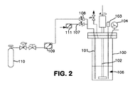
600ccのパル反応器を用いた合成(図2)
600ccのパル反応器100に、窒素下で、200mLの無水アニソール106を入れた。(反応装置を図2に示す)。この反応器を氷槽で冷却し(図示せず)、窒素を真空下で除去した。モノクロロシラン(65.7g、987ミリモル、200モル%過剰)を、浸漬管101を介して反応器へと入れた。反応器の内部圧力は、0℃でおよそ900Torrであった。次いで、流量計111及びチューブ107を介して供給される窒素で浸漬管をパージし、そのライン及び浸漬管を清掃した。この浸漬管を介して、無水アンモニアをすぐに反応器へと添加した。全ての試薬の添加及び反応時間を通して、反応器を、撹拌ロッド102を用いて250rpmの速度で撹拌した。温度及び圧力を、内部K型熱電対103及び0〜60psig圧力計104によってモニターした。無水アンモニア(7.5g、440ミリモル)を140mg/分の速度で、54分間、アンモニアシリンダー110(393ミリモル、6.7gのNH3を含む440ccのsslb、内部圧力はおよそ100psig)から流量計109及び弁108を介して、反応器へと添加した。反応混合物を0℃で更に45分間撹拌し、揮発分を動的真空下で取り除いた。生成物ガスを、−35℃に冷却された溶媒トラップ(U型トラップ)の下流に位置する、−196℃に保持されたU型トラップ(図示せず)にて収集した。溶媒トラップでは、2mLよりも少量の溶媒が収集された。生成物混合物を、440ccのステンレス鋼製レクチャーボトルへと移し、内容物を−78℃及び−196℃に冷却された2つのU型トラップを用いた分別濃縮により精製した。−78℃のトラップの内容物は9.84gのTSA(92ミリモル、収率83%)を含んでおり、−196℃のトラップの内容物は過剰量のMCS及び微量のシランを含んでいた。
Example 2
Synthesis using a 600cc Pal reactor (Figure 2)
A 600
実施例3〜実施例7は、表1に記載の条件で、実施例2の手順に従って行った。各実施例の収率は表1に記載する。 Examples 3 to 7 were performed according to the procedure of Example 2 under the conditions described in Table 1. The yield of each example is listed in Table 1.
初めの運転はガラス製反応器中で行い、残りは600ccの撹拌パル反応器中で行った。灰色の欄は、かなりの量の溶媒(トルエン)を含み得る生成物の収率を示している。 The first run was done in a glass reactor and the rest in a 600 cc stirred pal reactor. The gray column indicates the yield of product that may contain a significant amount of solvent (toluene).

下記実施例4及び実施例5では、収率及びモルパーセントの水素化物回収結果は、残留溶媒の汚染を含む可能性がある。「下流での塩(%)」は、各実験例で、クライオトラップにて収集された塩化アンモニウムの、最大計算量(理論量)に対する重量パーセントを示す。 In Examples 4 and 5 below, yields and mole percent hydride recovery results may include residual solvent contamination. “Downstream salt (%)” indicates the weight percent of ammonium chloride collected in the cryotrap with respect to the maximum calculated amount (theoretical amount) in each experimental example.
反応物は、反応条件を最適化して、生成物の分解並びに合成副産物、特にシラン及びシラザンポリマーの形成を引き起こし得る発熱反応からの熱の蓄積といった過剰な反応条件を避ける方法で接触する。例えば、このプロセスによると、反応の副産物であるハロゲン化アンモニウムを反応器に残留させ、ジシリルアミン及びトリシリルアミン等のガス状生成物は、溶媒混合物から真空ストリッピングして反応器外へと流出され、水素化物生成物の分解を引き起こし得るハロゲン化アンモニウム及び溶媒を実質的に含まない冷却トラップ容器にて収集される。合成の副産物であるハロゲン化アンモニウムは反応条件下では結晶性であり、そのためガス状生成物が反応器を上昇しその外へと流出し続けても、反応器内の溶媒中に残留する。トリシリルアミンの沸点は、1気圧で52℃である。 The reactants are contacted in a way that optimizes the reaction conditions to avoid excessive reaction conditions such as product decomposition and the accumulation of heat from exothermic reactions that can cause the formation of synthesis by-products, particularly silane and silazane polymers. For example, this process leaves the reaction by-product ammonium halide in the reactor, and gaseous products such as disilylamine and trisilylamine are stripped out of the reactor by vacuum stripping. Collected in a cold trap vessel substantially free of ammonium halide and solvent that can cause decomposition of the hydride product. The synthesis by-product, ammonium halide, is crystalline under the reaction conditions, so it remains in the solvent in the reactor even if the gaseous product continues to flow up and out of the reactor. The boiling point of trisilylamine is 52 ° C. at 1 atmosphere.
反応器は、減圧下又は約2000Torrまでの圧力下で運転する。反応器は、所定のどの反応温度においても、モノハロシランの蒸気圧とほぼ等しいか又はより小さい圧力に保持されることが好ましい。操作中、モノハロシランが大幅に減少すると、反応器の圧力は低下する。反応器の内部圧力は、約100torr〜約1500torrに維持することが好ましい。好ましい操作圧力は、約2気圧以下である。最大操作圧力は、約80psigである。 The reactor is operated under reduced pressure or pressure up to about 2000 Torr. The reactor is preferably maintained at a pressure approximately equal to or less than the vapor pressure of the monohalosilane at any given reaction temperature. During operation, if the monohalosilane is significantly reduced, the pressure in the reactor will drop. The internal pressure of the reactor is preferably maintained at about 100 torr to about 1500 torr. A preferred operating pressure is about 2 atmospheres or less. The maximum operating pressure is about 80 psig.
本発明は、トリシリルアミンを調製する方法であって、
(a)反応容器に溶媒を添加すること、
(b)溶媒にモノハロシランを濃縮して溶液を形成すること、
(c)前記溶液に無水アンモニアを添加して反応混合物を形成すること、
(d)前記反応混合物からトリシリルアミンを分離すること、及び
(e)前記トリシリルアミンを精製すること
を含む、方法に関する。
The present invention is a method for preparing trisilylamine, comprising:
(A) adding a solvent to the reaction vessel;
(B) concentrating monohalosilane in a solvent to form a solution;
(C) adding anhydrous ammonia to the solution to form a reaction mixture;
(D) separating the trisilylamine from the reaction mixture; and (e) purifying the trisilylamine.
反応容器に溶媒を添加した後、溶液を形成するように、モノハロシランを溶媒中に濃縮する前に溶媒の温度を任意に調節することができる。溶媒の温度は、約70℃〜約−78℃、好ましくは約60℃〜約−20℃、最も好ましくは約50℃〜約−20℃に調節することができる。 After adding the solvent to the reaction vessel, the temperature of the solvent can optionally be adjusted before the monohalosilane is concentrated in the solvent to form a solution. The temperature of the solvent can be adjusted to about 70 ° C to about -78 ° C, preferably about 60 ° C to about -20 ° C, most preferably about 50 ° C to about -20 ° C.
本発明で有用なモノハロシランとしては、モノフルオロシラン、モノクロロシラン、モノブロモシラン及びモノヨードシランが挙げられる。モノクロロシランが好ましい。 Monohalosilanes useful in the present invention include monofluorosilane, monochlorosilane, monobromosilane and monoiodosilane. Monochlorosilane is preferred.
実施例8〜実施例13の概要
TSAを、溶媒媒体としてアニソールを用い、4Lのオートクレーブ撹拌タンク反応器中で合成した。目標反応温度、過剰MCS量、及び溶媒とNH3との比を変化させながら、合計で6回運転を行った。この運転の結果に基づき、下記の反応条件が推奨される。
反応温度は約20℃〜約60℃である。
過剰MCS量は、モル−モル基準で、MCSの理論量に対して約25%〜約40%過剰である。
TSAの結果は理論収率に対するパーセントで表す。
溶媒とNH3との質量比は、約25:1〜約30:1である。溶媒とNH3との質量比は、本明細書を通して、整数で表す。
Overview of Examples 8-13 TSA was synthesized in a 4 L autoclave stirred tank reactor using anisole as the solvent medium. The operation was performed a total of 6 times while changing the target reaction temperature, the amount of excess MCS, and the ratio of the solvent and NH 3 . Based on the results of this operation, the following reaction conditions are recommended:
The reaction temperature is about 20 ° C to about 60 ° C.
The excess MCS amount is from about 25% to about 40% excess relative to the theoretical amount of MCS on a mole-mole basis.
TSA results are expressed as a percentage of the theoretical yield.
The mass ratio of solvent to NH 3 is about 25: 1 to about 30: 1. The mass ratio of solvent to NH 3 is expressed as an integer throughout this specification.
6回の運転中、反応器(典型的には10psia〜18psia)から液体窒素デュワー(LN2 dewar)中の受器へと真空ストリッピングを行った。ストリッピングの速度は、1/4インチライン及び標準シリンダーの弁開口部を介して、約2.2g/分であった。粗生成物を上記受器でフィルターを介して収集して、反応器からのいかなる塩の持ち込みも除去する。収集された粗分は、持ち込まれた溶媒、塩及び重分(heavies)であるなら、約6%(質量%)である。図3〜図7の各図中、X軸は時間(分)を表し、Y軸は、温度を示す上側の破線に対しては温度(℃)を表し、下側の実線に対しては圧力(psig)を表す。 During six runs, vacuum stripping was performed from the reactor (typically 10 psia to 18 psia) to a receiver in a liquid nitrogen dewar. The stripping rate was about 2.2 g / min via a 1/4 inch line and a standard cylinder valve opening. The crude product is collected at the receiver through a filter to remove any salt carry from the reactor. The collected crude is about 6% (mass%) if the solvent, salts and heavies brought in. 3 to 7, the X axis represents time (minutes), the Y axis represents temperature (° C.) for the upper broken line indicating temperature, and the pressure for the lower solid line. (Psig).
実施例の詳細
4Lの反応器中で、合計6回の運転を行った。
Example Details A total of 6 runs were carried out in a 4 L reactor.
実施例8
目標反応温度 0℃
過剰MCS 約63%
溶媒とNH3との質量比 30(30:1)
Example 8
Excess MCS about 63%
Mass ratio of solvent to NH 3 30 (30: 1)
反応器における温度及び圧力プロファイルを、時間の関数として図3に示す。図3中の上側の破線は温度(℃)を表し、下側の実線は圧力(psig)を表す。 The temperature and pressure profile in the reactor is shown in FIG. 3 as a function of time. The upper broken line in FIG. 3 represents temperature (° C.), and the lower solid line represents pressure (psig).
温度に見られる揺らぎは、混合が不十分であったことに因るものであった。更なる分析により、アニソールの粘度が、0℃では20℃よりも約33%高いことがわかった。アニソールの粘度がより高いことと、反応器中で塩の量が増加したこととが、温度の揺らぎに寄与した可能性がある。TSAの収率は84%であった。 The fluctuation seen in temperature was due to inadequate mixing. Further analysis showed that the viscosity of anisole was about 33% higher at 0 ° C than at 20 ° C. Higher anisole viscosity and increased salt content in the reactor may have contributed to temperature fluctuations. The yield of TSA was 84%.
実施例9
目標反応温度 25℃/室温
過剰MCS 26%
溶媒とNH3との質量比 28.4
Example 9
Mass ratio of solvent to NH 3 28.4
温度及び圧力プロファイルを、時間の関数として図4に示す。図4中の上側の線は温度(℃)を表し、下側の線は圧力(psig)を表す。TSAの収率は85.4%であった。 The temperature and pressure profile is shown in FIG. 4 as a function of time. The upper line in FIG. 4 represents temperature (° C.), and the lower line represents pressure (psig). The yield of TSA was 85.4%.
実施例10
目標量のアンモニアを2回添加した。この運転の結果、過剰量のNH3を用いると、TSA又はMCSは生成されず、生成物の受器に捕獲されないこと、液体中及び蒸気相中にはSiH4及びNH3のみが存在することがわかった。TSAの収率は0%であった。
Example 10
The target amount of ammonia was added twice. As a result of this operation, if an excess amount of NH 3 is used, no TSA or MCS will be produced and captured in the product receiver, and only SiH 4 and NH 3 will be present in the liquid and vapor phases. I understood. The yield of TSA was 0%.
一旦温めた受器における初期圧力は180psigより高く、これは室温におけるNH3の蒸気圧より高いものであった。そのため、NH3の大部分は液相中に存在し、この観察は、(1)NH3とTSAとが濃縮相において反応し、シランを形成すること、及び(2)このような反応は蒸気相では起こらないことを示している。 The initial pressure in the receiver once warmed was higher than 180 psig, which was higher than the vapor pressure of NH 3 at room temperature. Therefore, most of NH 3 is present in the liquid phase, and this observation shows that (1) NH 3 and TSA react in the concentrated phase to form silane, and (2) such a reaction is a vapor. It shows that it does not happen in the phase.
実施例11
目標反応温度 25℃/室温
過剰MCS 39%
溶媒とNH3との比 25
Example 11
Ratio of solvent to
この運転中の圧力及び温度プロファイルを図5に示す。図5中の上側の線は温度(℃)を表し、下側の線は圧力(psig)を表す。TSAの収率は94.3%であった。 The pressure and temperature profiles during this operation are shown in FIG. The upper line in FIG. 5 represents temperature (° C.), and the lower line represents pressure (psig). The yield of TSA was 94.3%.
運転中の様々な時間に、反応器の蒸気相を分析した。蒸気相の濃度プロファイルを以下に示す。 At various times during operation, the vapor phase of the reactor was analyzed. The concentration profile of the vapor phase is shown below.
運転中、MCSの濃度が徐々に低下し、それに対応して、SiH4、TSA及びDSA等の他の種の濃度が増加した。様々な種(下記表参照)の分圧を計算することにより、蒸気相中のSiH4は、少なくとも初期においては、供給されたMCS中のSiH4に起因することがわかった。 During operation, the concentration of MCS gradually decreased, and the concentrations of other species such as SiH 4 , TSA and DSA increased correspondingly. By calculating the partial pressure of various species (see table below), it was found that SiH 4 in the vapor phase was due at least initially to SiH 4 in the supplied MCS.
上記の結果によると、液相中のMCSが消費されると、時間の経過に伴うTSAの生成の増加とそれに対応するMCSの減少を伴って、反応が蒸気相に移動することがわかる。このSiH4量の増加は、(1)供給されたMCS中のSiH4、又は(2)塩の存在に起因するアニソール中のTSAの分解のいずれかであり得る。 From the above results, it can be seen that when MCS in the liquid phase is consumed, the reaction moves to the vapor phase with an increase in the production of TSA over time and a corresponding decrease in MCS. This increase in the amount of SiH 4 can be either (1) SiH 4 in the supplied MCS, or (2) degradation of TSA in anisole due to the presence of salt.
実施例12
目標反応温度 25℃又は室温
過剰MCS 42%
溶媒とNH3との質量比 25
NH3の添加速度 0.5g/分
Example 12
Mass ratio of solvent to
NH 3 addition rate 0.5 g / min
この運転中の圧力及び温度プロファイルは、図6に示す通りである。図6中の上側の線は温度(℃)を表し、下側の線は圧力(psig)を表す。TSAの収率は81.9%であった。 The pressure and temperature profiles during this operation are as shown in FIG. The upper line in FIG. 6 represents temperature (° C.), and the lower line represents pressure (psig). The yield of TSA was 81.9%.
反応器の圧力は、運転の大部分において約5psigに安定していたが、約120分後に急に上昇した。運転中の様々な時間において、反応器の蒸気相のサンプルを採取した。 The reactor pressure was stable at about 5 psig for most of the run, but rose rapidly after about 120 minutes. Samples of the vapor phase of the reactor were taken at various times during operation.
t=0(tは時間)における蒸気相中のシラン量は、供給されたMCS中のシランに起因するはずである。供給されたMCSを分析したところ、約1%のシランを含んでいることがわかり、添加したMCSの量に基づくと、供給物中に1.08グラムのSiH4が添加されていると見積もられる。シランの全体的な質量バランスによると供給されたMCS中のシランの約50%が蒸気相に存在し、残りはアニソール中に溶解していることがわかった。MCS及びアニソールを用いて独立した一連の試験を行ったところ、供給されたMCS中のSiH4の約66%が蒸気相を占めることがわかった。 The amount of silane in the vapor phase at t = 0 (t is time) should be due to the silane in the supplied MCS. Analysis of the supplied MCS reveals that it contains about 1% silane, and based on the amount of MCS added, it is estimated that 1.08 grams of SiH 4 is added to the feed. . According to the overall mass balance of silane, it was found that about 50% of the silane in the supplied MCS was in the vapor phase and the rest was dissolved in anisole. A series of independent tests using MCS and anisole showed that approximately 66% of the SiH 4 in the supplied MCS accounted for the vapor phase.
様々な種の分圧を反応時間の関数として求めた(下記表参照)。 The partial pressure of various species was determined as a function of reaction time (see table below).
各々の時間の分圧からシランの初期分圧を引くと、分圧の差は時間を関数として増加する。これは、時間の経過に伴う反応温度の上昇を補正しても当てはまる。これにより、(i)塩がより生成すると共に、TSAの分解がいくらか起こっていること、又は(ii)反応が進むにつれて、溶媒に溶解したシランがゆっくりと脱離していることがわかる。NH3の添加の最後に、蒸気相中のシランの量が、供給されたMCSを介した添加量を超えていることから、塩の存在下でのSiH4の放出を伴うTSAの分解が実証された。 If the initial partial pressure of silane is subtracted from the partial pressure of each time, the difference in partial pressure increases as a function of time. This is true even if the increase in reaction temperature over time is corrected. This indicates that (i) more salt is produced and some degradation of TSA occurs, or (ii) silane dissolved in the solvent is slowly desorbed as the reaction proceeds. At the end of the NH 3 addition, the amount of silane in the vapor phase exceeds the amount added via the supplied MCS, thus demonstrating the decomposition of TSA with the release of SiH 4 in the presence of salt. It was done.
実施例13
目標反応温度 25℃又は室温
過剰MCS 27%
溶媒とNH3との質量比 26
NH3添加速度 0.5g/分
Example 13
Mass ratio of solvent to
NH 3 addition rate 0.5 g / min
この運転中の圧力及び温度プロファイルは、図6に示す通りである。図7中の上側の線は温度(℃)を表し、下側の線は圧力(psig)を表す。TSAの収率は50.9%であった。 The pressure and temperature profiles during this operation are as shown in FIG. The upper line in FIG. 7 represents temperature (° C.), and the lower line represents pressure (psig). The yield of TSA was 50.9%.
時間を関数とする様々な種の分圧を下記の表に示す。 The various species of partial pressure as a function of time are shown in the table below.
NH3の添加を、t=153分で停止し、その時間にサンプルを採取した。反応器の内容物を、更に30分引き続き撹拌し、t=183分にサンプルを採取した。そして、反応器の内容物のみを真空ストリッピングした。 NH 3 addition was stopped at t = 153 minutes, at which time a sample was taken. The reactor contents were continuously stirred for another 30 minutes and a sample was taken at t = 183 minutes. Only the reactor contents were vacuum stripped.
再度、各々の時間のシランの分圧からシランの初期分圧を引くと、温度の上昇を補正した後であっても、蒸気相中のシラン量が時間と共に増加することがわかる。また、先の運転(実施例9、実施例11及び実施例12)ではNH3のピークは見られなかったが、この運転ではNH3の急増が見られた。主な違いは、25%という過剰量のMCS及び溶媒とNH3との質量比25が、両方とも操作条件の下限にあることである。
Again, when the initial partial pressure of silane is subtracted from the partial pressure of silane at each time, it can be seen that the amount of silane in the vapor phase increases with time, even after correcting for an increase in temperature. In the previous operation (Example 9, Example 11 and Example 12), no NH 3 peak was observed, but in this operation, a rapid increase in NH 3 was observed. The main difference is that an excess amount of MCS of 25% and a
ガスクロマトグラフィー法によりTSAを分析した。分析条件を以下に示す。 TSA was analyzed by gas chromatography. The analysis conditions are shown below.
本出願は、2011年10月7日付けで出願された、「トリシリルアミンの濃縮相による製造装置及び製造方法(APPARATUS AND METHOD FOR THE CONDENSED PHASE PRODUCTION OF TRISILYLAMINE)」と題する米国仮特許出願第61/544,468号の優先権を主張するものであり、この開示は引用することにより本明細書の一部をなすものとする。 This application is filed on Oct. 7, 2011, and is a US Provisional Patent Application No. 61 entitled “Apparatus and Method for the Condensed Phase Production of Trisylamine”. No. / 544,468, the priority of which is hereby incorporated by reference.
本発明の具体的な好ましい実施形態を説明したが、これらは本発明の範囲の限定を意図するものではない。添付の特許請求の範囲の真の趣旨及び範囲から逸脱しない範囲で、種々の変更、代替構造及び均等物を採用することができる。 While specific preferred embodiments of the invention have been described, they are not intended to limit the scope of the invention. Various modifications, alternative constructions and equivalents may be employed without departing from the true spirit and scope of the appended claims.
Claims (12)
(a)反応容器に溶媒を添加すること、
(b)前記溶媒にモノハロシランを添加して溶液を形成すること、
(c)前記溶液に無水アンモニアを添加して反応混合物を形成すること、
(d)前記反応混合物中においてトリシリルアミンを形成すること、
(e)前記反応混合物からシリルアミンを分離すること、及び
(f)前記シリルアミンを精製すること
を含み、
前記溶媒がモノハロシラン、アンモニア、並びにモノハロシラン及びアンモニアの反応混合物から形成される生成物、並びにトリシリルアミンと反応しない方法。 A method for preparing trisilylamine, comprising:
(A) adding a solvent to the reaction vessel;
(B) adding a monohalosilane to the solvent to form a solution;
(C) adding anhydrous ammonia to the solution to form a reaction mixture;
(D) forming trisilylamine in the reaction mixture;
(E) separating the silyl amine from the reaction mixture, and (f) viewing including purifying said silyl amine,
A process wherein the solvent does not react with monohalosilane, ammonia, and the product formed from the reaction mixture of monohalosilane and ammonia, and trisilylamine .
Applications Claiming Priority (3)
| Application Number | Priority Date | Filing Date | Title |
|---|---|---|---|
| US201161544468P | 2011-10-07 | 2011-10-07 | |
| US61/544,468 | 2011-10-07 | ||
| PCT/US2012/058764 WO2013052673A2 (en) | 2011-10-07 | 2012-10-04 | Apparatus and method for the condensed phase production of trisilylamine |
Publications (3)
| Publication Number | Publication Date |
|---|---|
| JP2014528898A JP2014528898A (en) | 2014-10-30 |
| JP2014528898A5 JP2014528898A5 (en) | 2015-11-26 |
| JP6175439B2 true JP6175439B2 (en) | 2017-08-02 |
Family
ID=48042206
Family Applications (1)
| Application Number | Title | Priority Date | Filing Date |
|---|---|---|---|
| JP2014534723A Active JP6175439B2 (en) | 2011-10-07 | 2012-10-04 | Apparatus and method for the production of trisilylamine by concentrated phase |
Country Status (9)
| Country | Link |
|---|---|
| US (1) | US8568682B2 (en) |
| EP (2) | EP3590888B1 (en) |
| JP (1) | JP6175439B2 (en) |
| KR (1) | KR101970850B1 (en) |
| CN (1) | CN103958401B (en) |
| CA (1) | CA2851242C (en) |
| SG (1) | SG11201401185VA (en) |
| TW (2) | TWI579235B (en) |
| WO (1) | WO2013052673A2 (en) |
Families Citing this family (18)
| Publication number | Priority date | Publication date | Assignee | Title |
|---|---|---|---|---|
| US9701540B2 (en) * | 2011-10-07 | 2017-07-11 | L'Air Liquide, Société Anonyme pour l'Etude et l'Exploitation des Procédés Georges Claude | Apparatus and method for the condensed phase production of trisilylamine |
| US9446958B2 (en) | 2011-10-07 | 2016-09-20 | L'Air Liquide Societe Anonyme L'Etude Et L'Exploitation Des Procedes Georges Claude | Apparatus and method for the condensed phase production of trisilylamine |
| JP5877702B2 (en) * | 2011-12-14 | 2016-03-08 | 株式会社ニューフレアテクノロジー | Film forming apparatus and film forming method |
| US20130209343A1 (en) * | 2012-02-10 | 2013-08-15 | American Air Liquide, Inc. | Liquid phase synthesis of trisilylamine |
| WO2014181194A2 (en) * | 2013-03-28 | 2014-11-13 | L'air Liquide Societe Anonyme Pour I'etude Et L'exploitation Des Procedes Georges Claude | Apparatus and method for the condensed phase production of trisilylamine |
| DE102013209802A1 (en) * | 2013-05-27 | 2014-11-27 | Evonik Industries Ag | Process for the coupled preparation of trisilylamine and polysilazanes having a molecular weight of up to 500 g / mol |
| US9284198B2 (en) | 2013-06-28 | 2016-03-15 | Air Products And Chemicals, Inc. | Process for making trisilylamine |
| SG11201602301WA (en) | 2013-09-27 | 2016-04-28 | Antonio Sanchez | Amine substituted trisilylamine and tridisilylamine compounds |
| DE102014204785A1 (en) * | 2014-03-14 | 2015-09-17 | Evonik Degussa Gmbh | Process for the preparation of pure trisilylamine |
| US9777025B2 (en) | 2015-03-30 | 2017-10-03 | L'Air Liquide, Société pour l'Etude et l'Exploitation des Procédés Georges Claude | Si-containing film forming precursors and methods of using the same |
| US11124876B2 (en) | 2015-03-30 | 2021-09-21 | L'Air Liquide, Société Anonyme pour l'Etude et l'Exploitation des Procédés Georges Claude | Si-containing film forming precursors and methods of using the same |
| CN108602839B (en) * | 2015-12-18 | 2021-06-29 | 南大光电半导体材料有限公司 | A process for preparing an organoaminosilane; method for producing silylamines from organoaminosilanes |
| US10192734B2 (en) | 2016-12-11 | 2019-01-29 | L'Air Liquide, Société Anonyme pour l'Etude et l'Exploration des Procédés Georges Claude | Short inorganic trisilylamine-based polysilazanes for thin film deposition |
| CN108394876B (en) * | 2017-02-07 | 2021-04-02 | 新疆晶硕新材料有限公司 | Nitrogen silane and production method thereof, silicon nitride and production method thereof |
| CN108147378B (en) * | 2018-02-07 | 2019-08-20 | 浙江博瑞电子科技有限公司 | A kind of refining methd of trimethylsilyl amine |
| KR20220116432A (en) | 2019-10-22 | 2022-08-23 | 린데 게엠베하 | Systems and processes for the production of trisilylamine |
| KR102435330B1 (en) * | 2020-08-21 | 2022-08-23 | 에스케이스페셜티 주식회사 | Apparatus for manufacturing trisilylamine and Method for manufacturing the same |
| CN114409547A (en) * | 2022-01-27 | 2022-04-29 | 浙江普洛康裕制药有限公司 | Continuous production method and device of amantadine |
Family Cites Families (14)
| Publication number | Priority date | Publication date | Assignee | Title |
|---|---|---|---|---|
| US3809713A (en) | 1973-03-01 | 1974-05-07 | Union Carbide Corp | Process for producing silazane compounds |
| JPS5112608B2 (en) * | 1973-05-29 | 1976-04-21 | ||
| JPS54135098A (en) * | 1978-04-06 | 1979-10-19 | Youngu Yun Sun | Cylinder lock |
| JPS608967B2 (en) * | 1978-04-11 | 1985-03-07 | 旭硝子株式会社 | How to make silicon nitride |
| US4397828A (en) * | 1981-11-16 | 1983-08-09 | Massachusetts Institute Of Technology | Stable liquid polymeric precursor to silicon nitride and process |
| US5132354A (en) * | 1990-06-15 | 1992-07-21 | Ethyl Corporation | Silicon nitride precursor polymer |
| US5968611A (en) | 1997-11-26 | 1999-10-19 | The Research Foundation Of State University Of New York | Silicon nitrogen-based films and method of making the same |
| JP4358492B2 (en) * | 2002-09-25 | 2009-11-04 | レール・リキード−ソシエテ・アノニム・プール・レテュード・エ・レクスプロワタシオン・デ・プロセデ・ジョルジュ・クロード | Method for producing silicon nitride film or silicon oxynitride film by thermal chemical vapor deposition |
| US7592402B2 (en) * | 2004-04-30 | 2009-09-22 | Sumitomo Chemical Company, Limited | Process for producing modified particle; carrier; catalyst component for addition polymerization; process for producing catalyst for addition polymerization; and process for producing addition polymer |
| JP4622350B2 (en) * | 2004-04-30 | 2011-02-02 | 住友化学株式会社 | Modified particles and method for producing the same, carrier, catalyst component for addition polymerization, catalyst for addition polymerization, and method for producing addition polymer |
| JP5589295B2 (en) * | 2009-03-30 | 2014-09-17 | 宇部興産株式会社 | Nitrogen-containing silane compound powder and method for producing the same |
| RU2540618C2 (en) | 2009-06-04 | 2015-02-10 | ВОЛТЕЙКС, ЭлЭлСи. | Method and device to produce trisilylamine |
| US20110136347A1 (en) * | 2009-10-21 | 2011-06-09 | Applied Materials, Inc. | Point-of-use silylamine generation |
| US8461367B2 (en) | 2010-01-15 | 2013-06-11 | Shin-Etsu Chemical Co., Ltd. | Preparation process of trisilylamine |
-
2012
- 2012-10-04 WO PCT/US2012/058764 patent/WO2013052673A2/en active Application Filing
- 2012-10-04 CN CN201280049320.5A patent/CN103958401B/en active Active
- 2012-10-04 SG SG11201401185VA patent/SG11201401185VA/en unknown
- 2012-10-04 CA CA2851242A patent/CA2851242C/en active Active
- 2012-10-04 EP EP19187693.7A patent/EP3590888B1/en active Active
- 2012-10-04 US US13/645,184 patent/US8568682B2/en active Active
- 2012-10-04 JP JP2014534723A patent/JP6175439B2/en active Active
- 2012-10-04 KR KR1020147012279A patent/KR101970850B1/en active IP Right Grant
- 2012-10-04 EP EP12838215.7A patent/EP2763934B1/en active Active
- 2012-10-08 TW TW101137127A patent/TWI579235B/en active
- 2012-10-08 TW TW106101260A patent/TW201731765A/en unknown
Also Published As
| Publication number | Publication date |
|---|---|
| EP2763934A2 (en) | 2014-08-13 |
| CA2851242C (en) | 2021-02-23 |
| CN103958401A (en) | 2014-07-30 |
| EP3590888B1 (en) | 2022-02-16 |
| SG11201401185VA (en) | 2014-04-28 |
| US20130089487A1 (en) | 2013-04-11 |
| WO2013052673A2 (en) | 2013-04-11 |
| TW201731765A (en) | 2017-09-16 |
| KR101970850B1 (en) | 2019-04-19 |
| EP2763934B1 (en) | 2019-09-04 |
| US8568682B2 (en) | 2013-10-29 |
| KR20140098071A (en) | 2014-08-07 |
| EP3590888A1 (en) | 2020-01-08 |
| CN103958401B (en) | 2015-09-02 |
| JP2014528898A (en) | 2014-10-30 |
| WO2013052673A3 (en) | 2013-07-11 |
| TW201326042A (en) | 2013-07-01 |
| EP2763934A4 (en) | 2015-04-22 |
| CA2851242A1 (en) | 2013-04-11 |
| TWI579235B (en) | 2017-04-21 |
Similar Documents
| Publication | Publication Date | Title |
|---|---|---|
| JP6175439B2 (en) | Apparatus and method for the production of trisilylamine by concentrated phase | |
| EP1720800A1 (en) | Process for producing silicon | |
| CN104136366A (en) | Liquid phase synthesis of trisilylamine | |
| KR102065329B1 (en) | Process of synthesizing diisopropylaminw-disilanes | |
| US10030038B2 (en) | Monoaminosilane compounds | |
| US10030037B2 (en) | Diaminosilane compounds | |
| US9701540B2 (en) | Apparatus and method for the condensed phase production of trisilylamine | |
| US9446958B2 (en) | Apparatus and method for the condensed phase production of trisilylamine | |
| TWI623491B (en) | Apparatus and method for the condensed phase production of trisilylamine | |
| US8551438B2 (en) | Production of silanes by acid hydrolysis of alloys of silicon and of alkaline-earth metals or alkaline-earth metal silicides | |
| JP4904032B2 (en) | Process for producing purified borazine compound | |
| JPH01197489A (en) | Synthesis of high purity dimethylaluminum hydride | |
| JP5213408B2 (en) | Method for handling alkali borohydride and method for producing borazine compound | |
| JPS61174108A (en) | Production of silicon imide or polysilazane | |
| JP2000044576A (en) | Purification of organic silanes | |
| JP2000095784A (en) | Purification of methylsilane | |
| JPH0480847B2 (en) | ||
| JPH0470247B2 (en) |
Legal Events
| Date | Code | Title | Description |
|---|---|---|---|
| A521 | Request for written amendment filed |
Free format text: JAPANESE INTERMEDIATE CODE: A523 Effective date: 20151002 |
|
| A621 | Written request for application examination |
Free format text: JAPANESE INTERMEDIATE CODE: A621 Effective date: 20151002 |
|
| A711 | Notification of change in applicant |
Free format text: JAPANESE INTERMEDIATE CODE: A711 Effective date: 20151210 |
|
| A521 | Request for written amendment filed |
Free format text: JAPANESE INTERMEDIATE CODE: A821 Effective date: 20151210 |
|
| A521 | Request for written amendment filed |
Free format text: JAPANESE INTERMEDIATE CODE: A523 Effective date: 20160219 |
|
| A521 | Request for written amendment filed |
Free format text: JAPANESE INTERMEDIATE CODE: A821 Effective date: 20160219 |
|
| A977 | Report on retrieval |
Free format text: JAPANESE INTERMEDIATE CODE: A971007 Effective date: 20160916 |
|
| A131 | Notification of reasons for refusal |
Free format text: JAPANESE INTERMEDIATE CODE: A131 Effective date: 20160921 |
|
| A601 | Written request for extension of time |
Free format text: JAPANESE INTERMEDIATE CODE: A601 Effective date: 20161215 |
|
| A521 | Request for written amendment filed |
Free format text: JAPANESE INTERMEDIATE CODE: A523 Effective date: 20170208 |
|
| A131 | Notification of reasons for refusal |
Free format text: JAPANESE INTERMEDIATE CODE: A131 Effective date: 20170322 |
|
| A521 | Request for written amendment filed |
Free format text: JAPANESE INTERMEDIATE CODE: A523 Effective date: 20170524 |
|
| TRDD | Decision of grant or rejection written | ||
| A01 | Written decision to grant a patent or to grant a registration (utility model) |
Free format text: JAPANESE INTERMEDIATE CODE: A01 Effective date: 20170621 |
|
| A61 | First payment of annual fees (during grant procedure) |
Free format text: JAPANESE INTERMEDIATE CODE: A61 Effective date: 20170710 |
|
| R150 | Certificate of patent or registration of utility model |
Ref document number: 6175439 Country of ref document: JP Free format text: JAPANESE INTERMEDIATE CODE: R150 |
|
| R250 | Receipt of annual fees |
Free format text: JAPANESE INTERMEDIATE CODE: R250 |
|
| R250 | Receipt of annual fees |
Free format text: JAPANESE INTERMEDIATE CODE: R250 |
|
| R250 | Receipt of annual fees |
Free format text: JAPANESE INTERMEDIATE CODE: R250 |
|
| R250 | Receipt of annual fees |
Free format text: JAPANESE INTERMEDIATE CODE: R250 |