JP6173467B2 - Dosing system, dosing method, and manufacturing method - Google Patents
Dosing system, dosing method, and manufacturing method Download PDFInfo
- Publication number
- JP6173467B2 JP6173467B2 JP2015533496A JP2015533496A JP6173467B2 JP 6173467 B2 JP6173467 B2 JP 6173467B2 JP 2015533496 A JP2015533496 A JP 2015533496A JP 2015533496 A JP2015533496 A JP 2015533496A JP 6173467 B2 JP6173467 B2 JP 6173467B2
- Authority
- JP
- Japan
- Prior art keywords
- piezoelectric actuator
- dosing
- piezoelectric
- actuator
- dosing system
- Prior art date
- Legal status (The legal status is an assumption and is not a legal conclusion. Google has not performed a legal analysis and makes no representation as to the accuracy of the status listed.)
- Active
Links
Images


Classifications
-
- B—PERFORMING OPERATIONS; TRANSPORTING
- B65—CONVEYING; PACKING; STORING; HANDLING THIN OR FILAMENTARY MATERIAL
- B65D—CONTAINERS FOR STORAGE OR TRANSPORT OF ARTICLES OR MATERIALS, e.g. BAGS, BARRELS, BOTTLES, BOXES, CANS, CARTONS, CRATES, DRUMS, JARS, TANKS, HOPPERS, FORWARDING CONTAINERS; ACCESSORIES, CLOSURES, OR FITTINGS THEREFOR; PACKAGING ELEMENTS; PACKAGES
- B65D25/00—Details of other kinds or types of rigid or semi-rigid containers
- B65D25/38—Devices for discharging contents
- B65D25/40—Nozzles or spouts
- B65D25/42—Integral or attached nozzles or spouts
-
- B—PERFORMING OPERATIONS; TRANSPORTING
- B05—SPRAYING OR ATOMISING IN GENERAL; APPLYING FLUENT MATERIALS TO SURFACES, IN GENERAL
- B05B—SPRAYING APPARATUS; ATOMISING APPARATUS; NOZZLES
- B05B1/00—Nozzles, spray heads or other outlets, with or without auxiliary devices such as valves, heating means
- B05B1/02—Nozzles, spray heads or other outlets, with or without auxiliary devices such as valves, heating means designed to produce a jet, spray, or other discharge of particular shape or nature, e.g. in single drops, or having an outlet of particular shape
-
- B—PERFORMING OPERATIONS; TRANSPORTING
- B05—SPRAYING OR ATOMISING IN GENERAL; APPLYING FLUENT MATERIALS TO SURFACES, IN GENERAL
- B05B—SPRAYING APPARATUS; ATOMISING APPARATUS; NOZZLES
- B05B17/00—Apparatus for spraying or atomising liquids or other fluent materials, not covered by the preceding groups
- B05B17/04—Apparatus for spraying or atomising liquids or other fluent materials, not covered by the preceding groups operating with special methods
- B05B17/06—Apparatus for spraying or atomising liquids or other fluent materials, not covered by the preceding groups operating with special methods using ultrasonic or other kinds of vibrations
- B05B17/0607—Apparatus for spraying or atomising liquids or other fluent materials, not covered by the preceding groups operating with special methods using ultrasonic or other kinds of vibrations generated by electrical means, e.g. piezoelectric transducers
- B05B17/0623—Apparatus for spraying or atomising liquids or other fluent materials, not covered by the preceding groups operating with special methods using ultrasonic or other kinds of vibrations generated by electrical means, e.g. piezoelectric transducers coupled with a vibrating horn
-
- B—PERFORMING OPERATIONS; TRANSPORTING
- B05—SPRAYING OR ATOMISING IN GENERAL; APPLYING FLUENT MATERIALS TO SURFACES, IN GENERAL
- B05B—SPRAYING APPARATUS; ATOMISING APPARATUS; NOZZLES
- B05B17/00—Apparatus for spraying or atomising liquids or other fluent materials, not covered by the preceding groups
- B05B17/04—Apparatus for spraying or atomising liquids or other fluent materials, not covered by the preceding groups operating with special methods
- B05B17/06—Apparatus for spraying or atomising liquids or other fluent materials, not covered by the preceding groups operating with special methods using ultrasonic or other kinds of vibrations
- B05B17/0607—Apparatus for spraying or atomising liquids or other fluent materials, not covered by the preceding groups operating with special methods using ultrasonic or other kinds of vibrations generated by electrical means, e.g. piezoelectric transducers
- B05B17/0653—Details
- B05B17/0669—Excitation frequencies
-
- B—PERFORMING OPERATIONS; TRANSPORTING
- B05—SPRAYING OR ATOMISING IN GENERAL; APPLYING FLUENT MATERIALS TO SURFACES, IN GENERAL
- B05C—APPARATUS FOR APPLYING FLUENT MATERIALS TO SURFACES, IN GENERAL
- B05C5/00—Apparatus in which liquid or other fluent material is projected, poured or allowed to flow on to the surface of the work
- B05C5/02—Apparatus in which liquid or other fluent material is projected, poured or allowed to flow on to the surface of the work the liquid or other fluent material being discharged through an outlet orifice by pressure, e.g. from an outlet device in contact or almost in contact, with the work
- B05C5/0225—Apparatus in which liquid or other fluent material is projected, poured or allowed to flow on to the surface of the work the liquid or other fluent material being discharged through an outlet orifice by pressure, e.g. from an outlet device in contact or almost in contact, with the work characterised by flow controlling means, e.g. valves, located proximate the outlet
- B05C5/0229—Apparatus in which liquid or other fluent material is projected, poured or allowed to flow on to the surface of the work the liquid or other fluent material being discharged through an outlet orifice by pressure, e.g. from an outlet device in contact or almost in contact, with the work characterised by flow controlling means, e.g. valves, located proximate the outlet the valve being a gate valve or a sliding valve
-
- G—PHYSICS
- G01—MEASURING; TESTING
- G01F—MEASURING VOLUME, VOLUME FLOW, MASS FLOW OR LIQUID LEVEL; METERING BY VOLUME
- G01F11/00—Apparatus requiring external operation adapted at each repeated and identical operation to measure and separate a predetermined volume of fluid or fluent solid material from a supply or container, without regard to weight, and to deliver it
- G01F11/02—Apparatus requiring external operation adapted at each repeated and identical operation to measure and separate a predetermined volume of fluid or fluent solid material from a supply or container, without regard to weight, and to deliver it with measuring chambers which expand or contract during measurement
- G01F11/021—Apparatus requiring external operation adapted at each repeated and identical operation to measure and separate a predetermined volume of fluid or fluent solid material from a supply or container, without regard to weight, and to deliver it with measuring chambers which expand or contract during measurement of the piston type
-
- Y—GENERAL TAGGING OF NEW TECHNOLOGICAL DEVELOPMENTS; GENERAL TAGGING OF CROSS-SECTIONAL TECHNOLOGIES SPANNING OVER SEVERAL SECTIONS OF THE IPC; TECHNICAL SUBJECTS COVERED BY FORMER USPC CROSS-REFERENCE ART COLLECTIONS [XRACs] AND DIGESTS
- Y10—TECHNICAL SUBJECTS COVERED BY FORMER USPC
- Y10T—TECHNICAL SUBJECTS COVERED BY FORMER US CLASSIFICATION
- Y10T29/00—Metal working
- Y10T29/49—Method of mechanical manufacture
- Y10T29/49826—Assembling or joining
Description
本発明は、出口開口を備え、出口開口の領域には放出方向および/または後退方向に動かされ得る閉鎖エレメントが可動に配置されるノズルを用いた、液体から粘性のドージング材料または分配される媒体用のドージングシステムに関する。また本発明は、このようなドージング材料のドージング方法、およびこのようなドージングシステムの製造方法にも関する。 The invention relates to a liquid-to-viscous dosing material or dispensed medium using a nozzle with an outlet opening, in which a closing element is movably arranged in the region of the outlet opening which can be moved in the discharge direction and / or in the backward direction Relates to a dosing system. The invention also relates to a method for dosing such a dosing material and a method for producing such a dosing system.
液体から粘性のドージング材料、たとえば接着剤、塗料、印刷用ニス、はんだペーストのような結着剤において結着される導電物質、LED用のコンバータ材料(通常、充填材の含有量が多い粘性ペースト、特にセラミック充填材)などの分配が、そうしたドージング材料を標的表面に正確に塗布するために役立つ。例えば、導電物質は、電子回路基板に精密かつ正確に塗布することができ、マスキングやドクターブレードの使用などの比較的柔軟性のない手順に取って代わっている。特に困難なのは、ドージング材料を非常に精密に塗布すること、すなわち正しい時間に、正しい場所で、正確なドージング量を、標的表面に塗布することにある。これは、例えば、ドージングシステムのノズルを通じて1滴ずつ放出することによって達成することができ、それによって液滴のサイズおよび/または数が、ノズルの動作によって、可能な限り正確に予め定められる。あるいは、ドージング材料は、噴出によりスパッタリングされるか、霧状にスプレーすることも可能である。 Liquid to viscous dosing materials such as adhesives, paints, printing varnishes, conductive materials bound in binders such as solder pastes, converter materials for LEDs (usually viscous pastes with high filler content) (Especially ceramic fillers) helps to accurately apply such dosing material to the target surface. For example, conductive materials can be precisely and accurately applied to electronic circuit boards, replacing relatively inflexible procedures such as masking and the use of doctor blades. Particularly difficult is to apply the dosing material very precisely, that is, to apply the correct dosing amount to the target surface at the right time and place. This can be achieved, for example, by ejecting drops one by one through the nozzle of the dosing system, whereby the size and / or number of drops is predetermined as accurately as possible by the operation of the nozzle. Alternatively, the dosing material can be sputtered by spraying or sprayed in a mist.
特許文献1は、上述の種類のドージングシステムを開示しており、この文献では圧電アクチュエータがプランジャに接続され、プランジャを放出方向および/または抜き取り方向に移動させる。このようなシステムにより、非常に精密で非常に速いプランジャ動作が可能となる。しかしながら、これは場合によっては圧電アクチュエータの非常に速いストローク動作によってドージングシステム内に振動が引き起こされるという欠点を有し、これは滑らかな作動を顕著に低下させ、ドージングシステムに機械的な負荷をかけ得る。
本発明の目的は、上述のドージングシステムに改良をもたらすことである。詳細には、ドージングシステムおよび/またはその個別の構成要素の、振動および/または機械的負荷を減少させることに特に重点をおく。 An object of the present invention is to provide an improvement to the dosing system described above. In particular, particular emphasis is placed on reducing vibrations and / or mechanical loads of the dosing system and / or its individual components.
この目的は、請求項1のドージングシステム、請求項14のドージング方法、および請求項15の製造方法により達成される。
This object is achieved by the dosing system of
本発明によれば、閉鎖エレメントは、逆方向に接続される少なくとも2つの圧電アクチュエータに結合され、第1の圧電アクチュエータは動作中に伸長すると、閉鎖エレメントを後退方向に移動させ、第2の圧電アクチュエータは動作中に伸長すると、閉鎖エレメントを放出方向に移動させる。 In accordance with the present invention, the closure element is coupled to at least two piezoelectric actuators connected in opposite directions, and when the first piezoelectric actuator is extended during operation, the closure element is moved in the backward direction, When the piezoelectric actuator is extended during operation, it moves the closure element in the ejection direction.
閉鎖エレメントの結合は直接もたらされてもよく、すなわち閉鎖エレメントは、例えば第1の圧電アクチュエータおよび/または第2の圧電アクチュエータに直接接続されるか、または特定の構成に応じてこれらの間で保持される。その一方で、閉鎖エレメントは、例えば適切な結合または接続エレメント、レバー配置または任意の他の機構を通して、第1の圧電アクチュエータおよび/または第2の圧電アクチュエータに間接的に結合されてもよい。 The coupling of the closure element may be effected directly, i.e. the closure element is connected directly to, for example, the first piezoelectric actuator and / or the second piezoelectric actuator or between them depending on the particular configuration Retained. On the other hand, the closure element may be indirectly coupled to the first piezoelectric actuator and / or the second piezoelectric actuator, for example through a suitable coupling or connecting element, lever arrangement or any other mechanism.
本発明はゆえに、圧電アクチュエータの一方が、どの時点においても任意の方向に閉鎖エレメントを押すか押圧する(直接的または間接的に)、プッシュプッシュ構造を実現できる。換言すれば、第1のアクチュエータは伸長し、閉鎖エレメントを2つの方向のうちの一方の方向に押し、第2のアクチュエータは収縮し、それによって閉鎖エレメントが所望の方向に動くために必要なスペースを確保する。閉鎖エレメントが反対方向に動かされる場合、アクチュエータの機能は逆になる、すなわち第2のアクチュエータは再度伸長し、閉鎖エレメントを押し、一方、第1のアクチュエータが収縮してスペースを作る。 The present invention can therefore realize a push-push structure in which one of the piezoelectric actuators pushes or pushes (directly or indirectly) the closing element in any direction at any point in time. In other words, the first actuator extends and pushes the closure element in one of the two directions, the second actuator contracts, thereby the space required for the closure element to move in the desired direction. Secure. If the closure element is moved in the opposite direction, the function of the actuator is reversed, i.e. the second actuator expands again and pushes the closure element, while the first actuator contracts to make space.
引張荷重が圧電素子の損傷や完全な破壊を急速にもたらすおそれがある一方で、圧電素子は一般に圧縮下で弾力性があるので、特に安定した圧電アクチュエータがこの方法で提供される。 While tensile loads can quickly lead to damage or complete destruction of the piezoelectric element, piezoelectric elements are generally elastic under compression, so a particularly stable piezoelectric actuator is provided in this way.
アクチュエータの寸法、配置および制御は、収縮するアクチュエータが(小さい)逆圧をかけ続け、それによって伸長する圧電アクチュエータの一定の予圧を確実にするように選択されることが特に好ましく、それによってその動作の終わりに予圧が過度にかけられず、圧電素子の損傷をもたらし得る内部応力を防ぐか、あるいは最小限に抑える。この場合、これによって、閉鎖エレメントの放出方向への動作中だけでなく、後退方向への動作中においても、反対に向けられた圧縮力が2つのアクチュエータによって印加されるので、圧縮力の瞬間的な差が現在の動作方向を決定する。これによって、高頻度で非常に急な移行状態にある閉鎖エレメントの特に急速な動作が可能となる。 It is particularly preferred that the size, arrangement and control of the actuators are selected so that the contracting actuator continues to apply a (small) back pressure and thereby ensures a constant preload of the extending piezoelectric actuator, thereby its operation At the end of the process, preload is not applied excessively, preventing or minimizing internal stresses that can cause damage to the piezoelectric element. In this case, this causes the compressive force directed oppositely to be applied by the two actuators not only during movement of the closing element in the discharge direction but also in the backward direction, so The difference will determine the current direction of motion. This allows a particularly rapid operation of the closing element which is frequently in a very steep transition.
本発明のドージング材料用のドージング方法は、ノズルを有するドージングシステムによって達成され、ノズルは、出口開口を備え、出口開口の領域では第1の圧電アクチュエータの伸長により閉鎖エレメントが後退方向に動かされ、ノズルからドージング材料を放出するために第2の圧電アクチュエータの伸長により放出方向に動かされる。 The dosing method for the dosing material of the present invention is achieved by a dosing system having a nozzle, the nozzle comprising an outlet opening, in the region of the outlet opening, the closure element is moved in the retracting direction by extension of the first piezoelectric actuator, To release the dosing material from the nozzle, it is moved in the discharge direction by extension of the second piezoelectric actuator.
本発明のドージングシステムの製造方法は、少なくとも以下のステップを含んでいる。
出口開口を備えるノズルを設けるステップ。
ノズル領域に閉鎖エレメントを可動に配置するステップ。
閉鎖エレメントを少なくとも2つの圧電アクチュエータに結合するステップであって、圧電アクチュエータは、第1の圧電アクチュエータが動作中に伸長すると閉鎖エレメントを後退方向に動かし、第2の圧電アクチュエータが動作中に伸長すると閉鎖エレメントを放出方向に動かすように配置され、閉鎖エレメントと結合される、結合するステップ。
The manufacturing method of the dosing system of the present invention includes at least the following steps.
Providing a nozzle with an outlet opening.
Movably disposing a closure element in the nozzle region.
The closure element comprising the steps of binding at least two piezoelectric actuators, a piezoelectric actuator, a first piezoelectric actuator moves the the closure element extending during operation in the backward direction, elongation second piezoelectric actuator is operating is arranged between the closure element is to move in the discharge direction, is coupled to the closing element, the step of coupling.
閉鎖エレメントは、一体または複合体のエレメントと理解され、好ましくは例えばプランジャなど、例えば円筒状などの細長い形状を備え、シリコンを用いて製造されてもよい。一方で、閉鎖エレメントは、閉鎖通路内に配置され、可動に支持された円形または楕円形であってもよい。閉鎖エレメントは、内面でキャビティを画定または取り囲む閉鎖通路すなわち中空体、好ましくは円筒状の中空体に配置され、閉鎖エレメントが本発明に関連してキャビティを「閉鎖」するように、少なくとも部分的に、その内部に閉鎖エレメントが配置される。しかしながら、閉鎖動作はより複雑であってもよく、閉鎖エレメントによるキャビティの完全なシールを行う必要はない。すなわち本発明によるドージングシステムは、以下により詳細に記載するように、開放型システムであってもよい。 The closure element is understood as a monolithic or composite element, preferably comprising an elongated shape, for example a plunger, for example cylindrical, and may be manufactured using silicon. On the other hand, the closure element may be circular or elliptical, which is disposed in the closure passage and is movably supported. The closure element is disposed in a closure passage or hollow body, preferably a cylindrical hollow body, that defines or surrounds the cavity on its inner surface, at least partially such that the closure element “closes” the cavity in the context of the present invention. In the interior, a closure element is arranged. However, the closing operation may be more complex and it is not necessary to have a complete seal of the cavity by the closing element. That is, the dosing system according to the present invention may be an open system, as described in more detail below.
上述のように、本発明のドージングシステムは、閉鎖エレメントの自動制御動作のためのアクチュエータシステムを備え、このためアクチュエータシステムは、少なくとも2つの圧電アクチュエータを備える。圧電アクチュエータは、一般に、他の機械的、電気機械的、または空気圧/油圧システムと比較して、非常に正確で迅速な可制御性、特に短い反応時間という利点を有する。さらに圧電アクチュエータは、比較的小さいスペースしか必要としない。本発明に関連して、圧電アクチュエータは、例えば複数の層状の、または並列の隣接する圧電性結晶または結晶層または類似する圧電素子のいくつかのエレメントで構成される構成要素と理解することができるが、例えば構成されるそれぞれのエレメントを制御するために共有の電気接続を備えることによって、制御装置によって1つのものとして制御される複合体を形成する。アクチュエータ素子はそれぞれ、直列接続として機能してもよく、すなわち圧電素子の伸長が蓄積され、または並列接続として機能してもよく、すなわちアクチュエータ素子が、例えば有効な圧力領域を増やすために互いに並んで接続される。いくつかの並列アクチュエータ素子の場合、これらのそれぞれは、直列の圧電素子の層(ピエゾスタックと呼ばれる)として実現することができる。 As mentioned above, the dosing system of the present invention comprises an actuator system for automatic control operation of the closure element, so that the actuator system comprises at least two piezoelectric actuators. Piezoelectric actuators generally have the advantage of very precise and quick controllability, in particular a short reaction time, compared to other mechanical, electromechanical or pneumatic / hydraulic systems. Furthermore, the piezoelectric actuator requires a relatively small space. In the context of the present invention, a piezoelectric actuator can be understood as a component made up of several elements of, for example, a plurality of layered or parallel adjacent piezoelectric crystals or crystal layers or similar piezoelectric elements. Form a complex that is controlled as one by the controller, for example by providing a shared electrical connection to control each configured element. Each actuator element may function as a series connection, i.e. the extension of the piezoelectric elements may be accumulated, or may function as a parallel connection, i.e. the actuator elements line up with each other, e.g. to increase the effective pressure area. Connected. In the case of several parallel actuator elements, each of these can be realized as a layer of piezoelectric elements in series (called a piezo stack).
本発明の他の特に有利な実施形態および変形例が、従属クレームおよび以下の記載から明らかになる。この方法は、ノズルまたは計量装置に関する従属クレームの特徴を用いて、および以下の記載のとおり、さらに開発され、逆もまた同様である。さまざまな実施形態の特徴は、任意の方法で組み合わせることが可能で、本発明の範囲内でさらなる実施形態を与える。 Other particularly advantageous embodiments and variants of the invention emerge from the dependent claims and the following description. This method is further developed using the features of the dependent claims relating to the nozzle or the metering device and as described below, and vice versa. The features of the various embodiments can be combined in any manner and provide further embodiments within the scope of the invention.
第1の圧電アクチュエータおよび第2の圧電アクチュエータは、好ましくは、閉鎖エレメントの放出方向および後退方向が、実質的に圧電アクチュエータの作用方向軸に沿って、すなわち、作用方向軸と平行または好ましくは同軸になるように配置および形成される。アクチュエータの作用方向軸は、アクチュエータがその軸に沿って主な延伸方向を有し、その軸においてアクチュエータが所望の圧力をかけるまたは圧力部材として働く(仮想の)軸と理解される。アクチュエータの作用方向軸および閉鎖エレメントの放出または後退方向の平行配置、特に同軸配置により、閉鎖エレメントの動作において記録される有効電力損失は特に低くなる。これは、一方では閉鎖エレメントの精度を向上させ、他方では閉鎖エレメント部材の限度速度を上昇させ、それによってドージングシステム全体の効率を向上させる。 The first and second piezoelectric actuators preferably have the closing and releasing directions of the closure element substantially along the direction of action of the piezoelectric actuator, ie parallel or preferably coaxial with the direction of action of the piezoelectric actuator. To be arranged and formed. The direction of action axis of the actuator is understood as the (virtual) axis on which the actuator has a main extension direction along that axis, on which the actuator applies the desired pressure or acts as a pressure member. Due to the parallel arrangement, in particular the coaxial arrangement, of the operating direction axis of the actuator and the closing or releasing direction of the closing element, the effective power loss recorded in the operation of the closing element is particularly low. This, on the one hand, improves the accuracy of the closure element and on the other hand increases the limit speed of the closure element member, thereby improving the overall efficiency of the dosing system.
好ましくは、2つの圧電アクチュエータの作用方向軸は、単一の作用方向軸に一致する。この目的のために、第1の圧電アクチュエータおよび第2の圧電アクチュエータは、例えば作用方向軸に沿って前後に配置され得る。特に好ましい実施形態において、閉鎖エレメントの放出方向または後退方向は、その後この圧電アクチュエータの共通の作用方向軸に沿って位置する。 Preferably, the action direction axes of the two piezoelectric actuators coincide with a single action direction axis. For this purpose, the first piezoelectric actuator and the second piezoelectric actuator can be arranged back and forth, for example along the axis of action. In a particularly preferred embodiment, the closing or releasing direction of the closure element is then located along the common operating direction axis of this piezoelectric actuator.
これにより、閉鎖エレメントの開放または閉鎖方向は、特に、圧電アクチュエータを環状に実現した場合、または例えば閉鎖エレメントが動く有効軸の近くに配置される、いくつかのアクチュエータ素子が平行に動作する場合に、圧電アクチュエータの作用方向に同軸であってもよいし、他の方法で実現された圧電アクチュエータの場合に、作用方向と平行であってもよい。アクチュエータの作用方向と閉鎖エレメントの開放および閉鎖方向が同一のものは、閉鎖エレメントの動作において観察される電力損失が特に低い。これは、一方では閉鎖エレメントの精度を向上させ、他方では速度を上昇させ、それによってドージングシステム全体の効率を向上させる。これによりドージングシステムは、著しく高い共振周波数を達成でき、それに伴い高い効率を達成できる。 Thereby, the opening or closing direction of the closing element is particularly suitable when the piezoelectric actuator is realized in an annular form or when several actuator elements are operated in parallel, for example arranged close to the effective axis on which the closing element moves. Further, it may be coaxial with the direction of action of the piezoelectric actuator, or may be parallel to the direction of action in the case of a piezoelectric actuator realized by another method. A power loss observed in the operation of the closing element is particularly low if the direction of action of the actuator and the opening and closing direction of the closing element are the same. This on the one hand improves the accuracy of the closure element and on the other hand increases the speed, thereby improving the efficiency of the overall dosing system. This allows the dosing system to achieve a significantly higher resonance frequency and thus a higher efficiency.
詳細には、第1の圧電アクチュエータおよび第2の圧電アクチュエータが作用方向軸に沿って前後に配置される場合、閉鎖エレメントは、好ましくは、第1の圧電アクチュエータと第2の圧電アクチュエータとの間の結合部で、第1の圧電アクチュエータおよび/または第2の圧電アクチュエータに(直接的または間接的に)結合され得る。結合部は、一列に配置される2つの圧電アクチュエータの、境界面または境界端の間の空間と理解される。この目的のために、閉鎖エレメントの結合部分は、2つの圧電アクチュエータの間に「直列に配置される」。 In particular, when the first and second piezoelectric actuators are arranged back and forth along the working direction axis, the closing element is preferably between the first and second piezoelectric actuators. Of the first and / or second piezoelectric actuators (directly or indirectly). A joint is understood as a space between the boundary surfaces or the boundary edges of two piezoelectric actuators arranged in a row. For this purpose, the coupling part of the closure element is “arranged in series” between two piezoelectric actuators.
好ましくは、閉鎖エレメントは、第1および第2の圧電アクチュエータ間でしっかりと固定することができる。これは、圧電アクチュエータと閉鎖エレメントとの間の効果的な力の伝達につながり、それによって摩擦と荷重伝達損失を大きく減らし、それによって全体的なドージングシステムの有効性を向上させることに役立つ。さらに、閉鎖エレメントは、例えば第1または第2の圧電アクチュエータのキャビティにおいて、第1または第2の圧電アクチュエータにしっかりと固定され得る。 Preferably, the closure element can be secured between the first and second piezoelectric actuators. This leads to an effective force transfer between the piezoelectric actuator and the closure element, thereby greatly reducing friction and load transfer losses, thereby improving the effectiveness of the overall dosing system. Furthermore, the closure element can be secured to the first or second piezoelectric actuator, for example in the cavity of the first or second piezoelectric actuator.
ドージングシステムは、好ましくは、2つの圧電アクチュエータが組み合わさって、それらの作用方向軸に沿って常に同じ全長を有し、互いにその伸長を打ち消す、すなわち作動中の第1の圧電アクチュエータの動きが第2の圧電アクチュエータの動きを打ち消し、作動中の第2の圧電アクチュエータの動きが第1の圧電アクチュエータの動きを打ち消すように構成され得る。このようにして、ドージングシステムの全構造物(特に外側構造物)への機械的応力をできるだけ低く保つことができる。基本的には外側に伝わる動的移動はないので、慣性力を除いて、外側方向へ作用する力、例えばアクチュエータが配置され得るアクチュエータチャンバの外部に作用する力はほとんど生じない。好ましくは、それゆえ、作動中の第1の圧電アクチュエータの寸法変化は、第2の圧電アクチュエータの寸法変化を埋め合わせ、作動中の第2の圧電アクチュエータの寸法変化は、第1の圧電アクチュエータの寸法変化を埋め合わせる。このような相互の埋め合わせは、一方では、例えば寸法変化の方向においてサイズが等しい圧電アクチュエータ、好ましくは完全に同じように構成された圧電アクチュエータを用いることにより、両方の圧電アクチュエータの(好ましくは同一か、ほぼ同一の)ストローク長さによって達成される。他方では、関連する圧電アクチュエータのこのような寸法変化の相互の埋め合わせを確実にする制御信号を、動作中に生じるために、一方または両方の圧電アクチュエータに対して1つまたは2つ以上の制御装置が実現されなければならない。換言すれば、圧電アクチュエータおよびその制御装置の構造形態は、このような相互の埋め合わせを達成するように調整される。 The dosing system preferably combines the two piezoelectric actuators so that they always have the same overall length along their direction of action and cancel their extension to each other, i.e. the movement of the first piezoelectric actuator in operation is the first. The movement of the second piezoelectric actuator can be canceled and the movement of the second piezoelectric actuator in operation can be configured to cancel the movement of the first piezoelectric actuator. In this way, the mechanical stress on the entire structure (especially the outer structure) of the dosing system can be kept as low as possible. Since there is basically no dynamic movement transmitted to the outside, there is almost no force acting in the outward direction, for example, the force acting outside the actuator chamber in which the actuator can be arranged, except for inertial forces. Preferably, therefore, the dimensional change of the first piezoelectric actuator during operation compensates for the dimensional change of the second piezoelectric actuator, and the dimensional change of the second piezoelectric actuator during operation is the dimension of the first piezoelectric actuator. Make up for change. Such mutual compensation is achieved on the one hand by using, for example, piezoactuators of equal size in the direction of dimensional change, preferably piezoactuators configured in exactly the same way (both preferably being the same). (Almost identical) is achieved by the stroke length. On the other hand, one or more control devices for one or both piezoelectric actuators in order to generate a control signal during operation that ensures mutual compensation of such dimensional changes of the associated piezoelectric actuators. Must be realized. In other words, the structural forms of the piezoelectric actuator and its control device are adjusted to achieve such mutual compensation.
上述のように、閉鎖エレメントは、液滴状、球状、楕円形状、不規則形状、一方側または両側が円錐状に実現されることが通常可能である。しかしながら、ノズルが、その長手方向の延伸を通して閉鎖エレメントの有効方向を定める閉鎖エレメントを備えることが特に好ましい。好ましくは、ノズルは長いプランジャを備える。そのようなプランジャは基本的に円筒状の構造を備えるが、その外面上の部分に突出部または凹部を備えてもよく、それはまた貫通孔として実現されてもよい(これは全ての閉鎖エレメントの実現に当てはまる)。そのような突出物または凹部は、閉鎖エレメントを他の機械的装置の係合エレメントと接続するために特に役立つことができる。これらの係合ポイントによって、閉鎖エレメントの制御された動作のために、圧力ばめまたは形状嵌合が、そのような装置を用いて達成され得る。 As mentioned above, the closure element can usually be realized in the form of a droplet, a sphere, an ellipse, an irregular shape, conical on one or both sides. However, it is particularly preferred that the nozzle comprises a closure element that defines the effective direction of the closure element through its longitudinal extension. Preferably, the nozzle comprises a long plunger. Such a plunger basically comprises a cylindrical structure, but may also be provided with a protrusion or a recess in a portion on its outer surface, which may also be realized as a through-hole (this is the case for all closure elements). Apply to realization). Such a protrusion or recess can be particularly useful for connecting the closure element with an engagement element of another mechanical device. With these engagement points, a pressure fit or shape fit can be achieved with such a device for the controlled movement of the closure element.
圧電アクチュエータの少なくとも1つは、円筒状の実現物を有し、好ましくは管状の実現物を有する。このようにして、その実現物は同様の形で実現され、特に好ましい横断面を備え得る。アクチュエータチャンバの円筒状の横断面が、矩形のチャンバと比較して、特に製造し易く、提供し易いため、その実現物は特に真っ直ぐにアクチュエータチャンバの中に挿入することができる。しかしながら、圧電アクチュエータの少なくとも1つは、円筒状でない形状に、例えば角度がついた形状に実現することも可能である。第1の円筒状圧電アクチュエータおよび第2の非円筒状アクチュエータの組み合わせもまた可能である。角度のついた(直角)アクチュエータは、よりシンプルに製造できるという利点を有するため、得やすい。一方で、円筒状および非円筒状アクチュエータの組み合わせは、円筒状、好ましくは管状のアクチュエータを用いる、すなわち閉鎖エレメントとの直接接続が有利である。他方では、非円筒状アクチュエータはある程度コストと労力を省くことができる。 At least one of the piezoelectric actuators has a cylindrical realization, preferably a tubular realization. In this way, the realization is realized in a similar manner and may have a particularly preferred cross section. Since the cylindrical cross section of the actuator chamber is particularly easy to manufacture and provide compared to a rectangular chamber, the realization can be inserted straight into the actuator chamber. However, at least one of the piezoelectric actuators can also be realized in a non-cylindrical shape, for example an angled shape. A combination of a first cylindrical piezoelectric actuator and a second non-cylindrical actuator is also possible. Angled (right angle) actuators are advantageous because they have the advantage of being simpler to manufacture. On the other hand, the combination of cylindrical and non-cylindrical actuators advantageously uses a cylindrical, preferably tubular actuator, ie a direct connection with the closure element. On the other hand, non-cylindrical actuators can save some cost and effort.
特に、閉鎖エレメントは、圧電アクチュエータの少なくとも一方の形状によって画定されたキャビティに少なくとも一部配置されてもよく、それによって他方の圧電アクチュエータも中空であることが可能である。一方の圧電アクチュエータのキャビティの領域における閉鎖エレメントのそのような配置は、特にコンパクトであり、圧電アクチュエータと閉鎖エレメント間で非常に精密でシンプルな力の伝達を可能にする。代替的には、管状の圧電アクチュエータは、例えば、並列に配置され、並列作動する、いくつかの、好ましくは少なくとも2つの、最も好ましくは少なくとも3つのアクチュエータ素子、特に圧電ロッドまたは同様のものに置き換えられてもよく、これらはグループとして(すなわち、1つのアクチュエータとして)制御され得る。これらの圧電アクチュエータ素子または圧電ロッド(例えばピエゾスタックとして実現される)は、閉鎖エレメント(またはそこに接続される結合素子)の周りで円周上に均等に配置されてもよく、管状の圧電アクチュエータと同じ効果を達成するために、グループとして(すなわち1つのアクチュエータとして)制御され得る。 In particular, the closure element may be arranged at least in part in a cavity defined by the shape of at least one of the piezoelectric actuators, so that the other piezoelectric actuator can also be hollow. Such an arrangement of the closing element in the area of the cavity of one piezoelectric actuator is particularly compact and allows a very precise and simple force transmission between the piezoelectric actuator and the closing element. Alternatively, the tubular piezoelectric actuator is replaced by several, preferably at least two, most preferably at least three actuator elements, in particular piezoelectric rods or the like, which are arranged in parallel and actuated in parallel. These may be controlled as a group (ie as one actuator). These piezoelectric actuator elements or piezoelectric rods (e.g. realized as a piezo stack) may be evenly arranged on the circumference around the closure element (or the coupling element connected thereto) Can be controlled as a group (ie as one actuator) to achieve the same effect.
しばしば、両方の圧電アクチュエータは全く同じに構成されることが好ましい。これは、両方の圧電アクチュエータを調整する労力を省くだけでなく、アクチュエータチャンバの実現の労力も省き、それによって制御プロセスの調整する労力も省く。 Often, it is preferred that both piezoelectric actuators be configured identically. This not only saves the effort of adjusting both piezoelectric actuators, but also saves the effort of realizing the actuator chamber, thereby reducing the effort of adjusting the control process.
上述のように、両方の圧電アクチュエータのうちの少なくとも一方は、好ましくはアクチュエータチャンバ内に配置される。特に有利なのは、両方の圧電アクチュエータが共通のアクチュエータチャンバ内に配置される場合である。これによって最適化が可能になり、特に損失が起こらないように両方の圧電アクチュエータの共働を最適に調整することができる。例えば、第1の圧電アクチュエータおよび第2の圧電アクチュエータの作動中、互いに影響される寸法変化のための最大合計寸法限度を定めることが可能になる。そのような最大合計寸法は、アクチュエータチャンバの内部寸法によってのみ定めることができる。しかしながら、定められた最大合計寸法が正確に達成されるように、内部寸法を減らすために、スペーサーもアクチュエータチャンバ内に配置されてもよい。そのようなスペーサーを用いて、特定の方法で、例えばスクリューまたは類似の調整エレメントを用いて、例えばアクチュエータチャンバの外部からスペーサーの精密な調整を行うことによって、合計寸法は変えることができる。 As described above, at least one of both piezoelectric actuators is preferably disposed within the actuator chamber. Particularly advantageous is when both piezoelectric actuators are arranged in a common actuator chamber. As a result, optimization is possible, and the cooperation of both piezoelectric actuators can be optimally adjusted so that no loss occurs. For example, during operation of the first and second piezoelectric actuators, it is possible to define a maximum total dimensional limit for dimensional changes that are affected by each other. Such maximum total dimensions can only be determined by the internal dimensions of the actuator chamber. However, spacers may also be placed in the actuator chamber to reduce internal dimensions so that a defined maximum total dimension is accurately achieved. With such a spacer, the total dimensions can be varied in a specific way, for example by using a screw or similar adjustment element, for example by fine adjustment of the spacer from outside the actuator chamber.
本発明によるドージングシステムにおいて、いくつかの機能的に異なるユニットが配置される。まず第一にノズル自体で、ドージング材料の放出を測定するように働き、次にアクチュエータシステムで、ノズル内で可動部(すなわち、特に閉鎖エレメント)を動かし、最後にドージング材料リザーバおよびノズルへのドージング材料のフィードラインで、ドージング材料を供給する。好ましくは、これらの機能的に分離可能なユニットは、別々の領域にも配置される。特に、ドージングシステムは、ノズルを取り囲む第1のハウジング部および少なくとも1つのアクチュエータ(例えば、少なくとも1つの圧電アクチュエータ)を保持する第2のハウジング部を備えることが好ましい。第1のハウジング部および第2のハウジング部は、好ましくは、ばね付勢式で互いに接続することができる。そのようなばね付勢は、アクチュエータシステムの作動中の振動を弱め、一定の耐性を与えるのに役立つ。さらに、ハウジング部は互いに接続を切ることができるので、これは保守中にアクチュエータシステムをノズル領域から完全に分離することを確実にする。同様に、好ましくは、ドージング材料リザーバもアクチュエータから、すなわち第1および第2の圧電アクチュエータから分離する。好ましくは、それはドージングシステムの他の部分に取り付け可能な独立したチャンバおよびフィードラインシステムとして実現され、スクリューおよびフィードラインスリーブを用いてドージングシステムのハウジングに接続することができる。したがって、それはノズル自体からも分離可能である。 In the dosing system according to the invention, several functionally different units are arranged. First the nozzle itself acts to measure the release of the dosing material, then the actuator system moves the moving part (ie, especially the closure element) within the nozzle, and finally the dosing material reservoir and the dosing to the nozzle The dosing material is supplied at the material feed line. Preferably, these functionally separable units are also arranged in separate areas. In particular, the dosing system preferably includes a first housing portion that surrounds the nozzle and a second housing portion that holds at least one actuator (eg, at least one piezoelectric actuator). The first housing part and the second housing part can preferably be connected to each other in a spring-biased manner. Such a spring bias helps to dampen vibration during operation of the actuator system and provide a certain tolerance. Furthermore, since the housing parts can be disconnected from each other, this ensures that the actuator system is completely separated from the nozzle area during maintenance. Similarly, preferably the dosing material reservoir is also separated from the actuator, i.e. from the first and second piezoelectric actuators. Preferably, it is implemented as an independent chamber and feedline system that can be attached to other parts of the dosing system and can be connected to the housing of the dosing system using screws and feedline sleeves. It can therefore also be separated from the nozzle itself.
本発明によると、閉鎖エレメントの動作は、少なくとも一対の圧電アクチュエータを用いて行われる。この目的のために、また圧力を調節するために、好ましくは、ドージングシステムは、アクチュエータシステムを制御するための、および/またはドージングシステムのドージング材料リザーバにおける圧力を制御するための電子制御装置を備える。この制御装置は、必ずしもドージングシステムのハウジング内部にある必要はなく、外部に配置することも可能である。制御装置は、制御ラインを用いて、ドージングシステムハウジングの内部に接続することができる。アクチュエータシステムは固有ロジックに基づいて動作しないが、電子制御装置によって「インテリジェントな」方法で制御され、例えばソフトウェア生成の制御信号をアクチュエータシステムに与えるプロセッサを備えてもよい。そのような制御装置は、14kHz域でのドージングクロック速度を達成でき、それは閉鎖エレメントの動作を非常に精密に制御できることを意味する。 According to the invention, the operation of the closure element is performed using at least a pair of piezoelectric actuators. For this purpose and to regulate the pressure, preferably the dosing system comprises an electronic controller for controlling the actuator system and / or for controlling the pressure in the dosing material reservoir of the dosing system. . This control device does not necessarily have to be inside the housing of the dosing system but can also be arranged outside. The control device can be connected to the interior of the dosing system housing using a control line. The actuator system does not operate based on inherent logic, but may be provided with a processor that is controlled in an “intelligent” manner by an electronic controller and provides, for example, software-generated control signals to the actuator system. Such a control device can achieve a dosing clock speed in the 14 kHz range, which means that the operation of the closure element can be controlled very precisely.
本発明の好ましい実施形態は、ドージングシステムが閉鎖通路を有するノズルを備えるいわゆるオープンシステムに関し、作動中に閉鎖通路内で閉鎖エレメントが開放および/または閉鎖方向に動かされ、自動制御装置によって制御され、それによって閉鎖通路は、同一平面上で閉鎖エレメントの横断面に対して開放および/または閉鎖方向に垂直である少なくとも1つの横断面に対して、閉鎖エレメントの外面と閉鎖通路の内面との間に開口ギャップを与えるように実現され、その開口ギャップは、少なくとも所々でドージング材料の出口通路を形成するように成形され、および/または寸法決めされる。 A preferred embodiment of the invention relates to a so-called open system in which the dosing system comprises a nozzle with a closed passage, during operation the closure element is moved in the opening and / or closing direction in the closed passage and is controlled by an automatic control device, Thereby, the closing channel is between the outer surface of the closing element and the inner surface of the closing channel with respect to at least one cross-section that is open and / or perpendicular to the closing direction in the same plane with respect to the cross-section of the closing element. Implemented to provide an open gap, the open gap being shaped and / or dimensioned to form an exit passage for dosing material at least in some places.
特に好ましい実施形態において、制御装置はこれに関連して、ドージング材料の粘度が開口ギャップの少なくとも1つの領域で低減されるように閉鎖エレメントを移動させるように実現される。 In a particularly preferred embodiment, the control device is implemented in this connection to move the closure element so that the viscosity of the dosing material is reduced in at least one region of the opening gap.
本発明に関連して、液体から粘性のドージング材料は、任意の液体または流動性を有する液体を含む任意の混合物と定義される。粘度の定義は、水の粘度より高い粘度から固体の性質に近い粘度までと幅があってもよい。好ましい実施形態において、ドージング材料は揺変性または剪断減粘性を有する、すなわちその粘度は撹拌状態より静止状態においての方が高くなり、静止状態に戻ると(場合によっては一定の静止時間の後)、粘度は少なくとも最初のより高い粘度に近づくということを用いる。「粘性の」という用語はまた、静止状態で固体の特性を持ち、撹拌時に流動可能な材料または媒体に適用され得る。 In the context of the present invention, a liquid-to-viscous dosing material is defined as any liquid or any mixture containing a fluid with fluidity. The definition of viscosity may vary from a viscosity higher than that of water to a viscosity close to the properties of the solid. In a preferred embodiment, the dosing material has thixotropic or shear thinning, i.e. its viscosity is higher in the quiescent state than in the agitated state and returns to the quiescent state (possibly after a certain rest time). It is used that the viscosity approaches at least the first higher viscosity. The term “viscous” can also be applied to a material or medium that has the properties of a solid in a stationary state and is flowable upon stirring.
閉鎖エレメントと閉鎖通路の相互作用は、ドージング材料が通ることができる十分な大きさの開口ギャップが、閉鎖エレメントと閉鎖通路との間に少なくとも所々定められるという点で、本明細書に記載するオープンドージングシステムの実現に関して決定的である。この開口ギャップは、ドージング材料の出口通路を形成し、好ましくはノズルの出口開口につながっている。適切に撹拌された状態で、ドージング材料は出口通路の中を流れることができる。撹拌されていない状態または粘度がわずかに低い場合の動作パターンにおいて、ドージング材料は、好ましくは開口ギャップによって画定される出口通路に残り、それ以上流れない。これは、ドージングシステムにおけるドージング材料の適用圧力条件および通常動作温度で、ドージング材料がもはや動かないあるいは少しだけ動くようになると流動は不可能または実質的に不可能になることを確実にするように、出口通路または開口ギャップの寸法が選択されることを意味する。 The interaction between the closing element and the closing passage is the opening described herein, in that a sufficiently large opening gap through which the dosing material can pass is defined between the closing element and the closing passage. It is decisive for the realization of the dosing system. This open gap forms an exit passage for the dosing material and is preferably connected to the exit opening of the nozzle. With proper agitation, the dosing material can flow through the outlet passage. In an unstirred state or operating pattern when the viscosity is slightly lower, the dosing material preferably remains in the exit passage defined by the open gap and does not flow further. This ensures that at the applied pressure conditions and normal operating temperature of the dosing material in the dosing system, flow is impossible or substantially impossible when the dosing material no longer moves or moves a little. Means that the dimensions of the exit passage or opening gap are selected.
これに関連して、閉鎖エレメントおよび関連する開口通路は、ドージング材料すなわちこの閉鎖によって保持される媒体に対して共に作用する。結局のところ、そのような閉鎖は、原則としてドージング材料が適切に撹拌された状態で比較的妨げられないで通ることができる開放アレンジメントを与えることによって形成されるが、閉鎖エレメントが閉鎖通路で動作を停止するとき、ドージング材料の揺変性または剪断減粘性のために自動的に閉鎖される。したがって、閉鎖通路に対して閉鎖エレメントの完全な静止状態の間、物質の流動は起こらない。ノズルの出口開口を閉じることは不要で、実のところ、出口開口は常に覆われない状態の方が好ましい。さらに、ドージング材料の意図的な分配は、さまざまな動作モードによって、下記のとおり制御することができる。 In this connection, the closure element and the associated open passage act together on the dosing material, ie the medium retained by this closure. After all, such a closure is formed in principle by providing an open arrangement that allows the dosing material to pass relatively unhindered in a properly agitated state, but the closure element operates in a closed passage When shutting down, it is automatically closed due to thixotropic or shear thinning of the dosing material. Thus, no material flow occurs during the complete rest of the closure element relative to the closure passage. It is not necessary to close the outlet opening of the nozzle, and indeed it is preferable that the outlet opening is not always covered. Furthermore, the intentional distribution of the dosing material can be controlled as follows by various modes of operation.
閉鎖通路の横断面に対する閉鎖エレメントの横断面の大きさは、一方では塗布されるドージング材料の粘度(あるいは撹拌状態での粘度)によって選択され、他方ではドージング材料にかけられる圧力によって選択される。次の経験則が適用される。
ドージング材料の圧力が高いほど、開口ギャップは小さくてよい。
ドージング材料の静止状態において、ドージング材料の粘度が低いほど、開口ギャップは小さくてよい。
撹拌状態において、ドージング材料の粘度が低いほど、開口ギャップは小さくてよい。
The size of the cross-section of the closing element relative to the cross-section of the closing passage is selected on the one hand by the viscosity of the dosing material to be applied (or the viscosity under stirring) and on the other hand by the pressure applied to the dosing material. The following rule of thumb applies:
The higher the pressure of the dosing material, the smaller the opening gap.
In the stationary state of the dosing material, the lower the viscosity of the dosing material, the smaller the opening gap.
In the stirring state, the lower the viscosity of the dosing material, the smaller the opening gap.
横断面における開口ギャップの大きさ、すなわち開口ギャップの横断面の面積は、閉鎖エレメントの静止状態の間に、ドージング材料が移動しないまたは同じ圧力条件下の自由流れと比較してはるかに少なく移動するように選択される。言い換えると、発明の原理は、閉鎖エレメントと閉鎖通路との間の開口ギャップが、開口ギャップにもかかわらず、ドージング材料の剪断減粘性のためにノズル内で閉鎖効果が起こるように、ドージング材料および/またはドージング材料にかけられた圧力に応じた寸法にすることにある。一方、開口ギャップはまた、閉鎖通路内での閉鎖エレメントの十分な動きがドージング材料の粘度を減らし、ドージング材料が閉鎖通路内で流れることを可能にし、定量供給を確実にするような寸法にされるべきである。このようにして、閉鎖エレメントが閉鎖通路内で動くとすぐに、開口ギャップはドージング材料の通路となる。したがって、閉鎖エレメントと閉鎖通路との協働によってもたらされた閉鎖効果は一時的なものであり、閉鎖エレメントの動きによって逆にされ、ドージング材料を撹拌し、ドージング材料が流れるようにする。 The size of the opening gap in the cross section, i.e. the area of the cross section of the opening gap, moves much less during the resting state of the closing element compared to free flow under the same pressure conditions where the dosing material does not move Selected as In other words, the principle of the invention is that the opening gap between the closing element and the closing passage is such that the closing effect occurs in the nozzle due to the shear thinning of the dosing material despite the opening gap. And / or dimensioning according to the pressure applied to the dosing material. On the other hand, the opening gap is also dimensioned such that sufficient movement of the closing element in the closed passage reduces the viscosity of the dosing material, allows the dosing material to flow in the closed passage and ensures a metered supply. Should be. In this way, the opening gap becomes a passage for dosing material as soon as the closing element moves in the closing passage. Thus, the closing effect provided by the cooperation of the closing element and the closing passage is temporary and is reversed by the movement of the closing element, stirring the dosing material and allowing the dosing material to flow.
そのような方法またはそのようなノズルによって、閉鎖エレメントが動かされるときにドージング材料が自動的に変わるか、またはそれらの粘性を減らせるように、ノズルの作動中に特定の、高粘性、揺変性および剪断減粘性のドージング材料を調製することが可能になる。ノズルを閉じるために閉鎖エレメントを出口開口の方へ押しやり、出口開口を覆わないように閉鎖エレメントをノズルの出口開口から引き離す、既知のノズル閉鎖とは対照的に、出口開口は常に開放しておくことができる。それでも上述の先行技術によって生じた短所は起こらない。また、ドージング材料にかけられる圧力は大幅に増やす必要はない。代わりに、低粘度ドージング材料にかけられる通常の圧力条件を与えることで十分である。同時に、ノズルの作動中にドージング材料の粘度を減らすことによってドージング材料を分配することが可能になり、より正確に分配することが可能になる。より正確な分配が可能になり、ドージング材料の各液滴の非常に精密に予め定められた液滴の放出が達成され得る。これはまた、分配速度、すなわち本発明のドージングシステムの潜在的な処理能力を向上させる。 With such a method or such a nozzle, the dosing material changes automatically when the closure element is moved, or a specific, highly viscous, thixotropic during operation of the nozzle so that their viscosity can be reduced. And a shear thinning dosing material can be prepared. In contrast to the known nozzle closure, the outlet opening is always open, pushing the closure element towards the outlet opening to close the nozzle and pulling the closing element away from the nozzle outlet opening so as not to cover the outlet opening. I can leave. Nevertheless, the disadvantages caused by the prior art described above do not occur. Also, the pressure applied to the dosing material need not be significantly increased. Instead, it is sufficient to provide the normal pressure conditions that are applied to the low viscosity dosing material. At the same time, it is possible to dispense the dosing material by reducing the viscosity of the dosing material during operation of the nozzle, and more accurately. More precise dispensing is possible and very precisely predetermined droplet ejection of each droplet of dosing material can be achieved. This also improves the distribution rate, i.e. the potential throughput of the dosing system of the present invention.
ドージング材料が開口ギャップ内で流れるようにするために、開口ギャップは、閉鎖エレメントの外面と閉鎖通路の内面との間に、ドージング材料の1つの粒子の高さ、好ましくは少なくとも3つの粒子が並ぶ長さ、特に好ましくは少なくとも0.05mmの長さに対応する、少なくとも1つの間隙を含むことが必要である。ドージング材料の少なくとも最大の粒子が開口ギャップの中を通れるようにすることに注意を払うべきである。「粒子」の用語は、これに関連して広く解釈される。それはポリマー鎖、またはポリマー鎖への煎断力の適用下で分離することができるポリマー鎖の部分を含む。「最大の粒子」は、この状況においては、粘度を大幅に減少させる煎断力の適用下で存在する粒子として定義することができる。特にポリマー鎖を含むドージング材料の場合において、粘度の減少はポリマー鎖を所々切断することによって生じ、それによってより小さい粒径にし、その中で最大の粒子が開口ギャップの中を通れなければならない。さらに最小の高さとは、主軸の方向に最小限に伸ばされて、ドージング材料の全ての粒子の中で最大の大きさを示すという意味においてドージング材料の最大の粒子の高さを意味する。この最小の高さは、粒子が固有の弾性の範囲内で圧縮されるときの粒径として理解されるべきである。 In order to allow the dosing material to flow in the opening gap, the opening gap is arranged between the outer surface of the closing element and the inner surface of the closing passage with the height of one particle of dosing material, preferably at least three particles aligned. It is necessary to include at least one gap corresponding to a length, particularly preferably a length of at least 0.05 mm. Care should be taken to allow at least the largest particles of dosing material to pass through the open gap. The term “particle” is broadly interpreted in this context. It comprises polymer chains, or portions of polymer chains that can be separated under the application of a severing force on the polymer chains. “Maximum particles” can be defined in this context as particles that exist under the application of a decoction force that significantly reduces the viscosity. Particularly in the case of dosing materials containing polymer chains, the reduction in viscosity occurs by breaking the polymer chains from place to place, thereby resulting in a smaller particle size in which the largest particles must pass through the open gap. Furthermore, the minimum height means the maximum particle height of the dosing material in the sense that it is stretched to a minimum in the direction of the main axis and exhibits the maximum size among all particles of the dosing material. This minimum height should be understood as the particle size when the particles are compressed within their inherent elasticity.
ドージング材料の流動は、特に、複数の粒子、すなわち2つ、好ましくは少なくとも3つの粒子が開口ギャップに並んでその大きさに適合するときに起こり得る。環状の開口ギャップが制御された通過流または制御された閉鎖効果を達成するのに特に適していることが実験によって示されている。これは、閉鎖エレメントの円形の横断面、好ましくは閉鎖通路内の閉鎖エレメントの軸方向の配置と組み合わせた閉鎖通路の内面の円形の横断面によって達成することができる。実験はまた、そのような円形の開口ギャップの場合、現在の標準的な圧力条件下で、0.1mm+/−10%の差異の範囲の横断面のギャップ幅は、閉鎖エレメントの動作状態で良い通過流を得るために、また閉鎖エレメントの静止状態で良い閉鎖を得るために特に適していることを示している。上述のタイプのドージング材料の場合、0.5〜8バールの標準的な圧力が現在適用されている。他の形状ももちろん可能である。 The flow of dosing material can occur especially when a plurality of particles, ie two, preferably at least three particles, are aligned with the size of the open gap. Experiments have shown that an annular opening gap is particularly suitable for achieving a controlled flow through or controlled closing effect. This can be achieved by a circular cross section of the closing element, preferably a circular cross section of the inner surface of the closing passage combined with an axial arrangement of the closing element in the closing passage. Experiments have also shown that for such circular opening gaps, under the current standard pressure conditions, a cross-sectional gap width in the range of 0.1 mm +/− 10% difference may be the operating condition of the closing element. It is particularly suitable for obtaining a flow through and for obtaining a good closure in the stationary state of the closure element. For the above-mentioned types of dosing materials, standard pressures of 0.5-8 bar are currently applied. Other shapes are of course possible.
閉鎖エレメントの外面と閉鎖通路の内面との間の開口ギャップの空間、すなわち開口ギャップの間隙の上限は、次のように定められる。間隙のためにドージング材料に作用する流動抵抗は、ノズルの出口開口の領域でドージング材料に作用する流動抵抗と少なくとも同じ大きさでなければならない。閉鎖通路の領域内の流動抵抗が出口開口の領域内の流動抵抗より小さい場合、ドージング材料は出口ノズルから放出されないだろう。出口開口の長さが常に0.5mmで、ドージング材料が通る開口ギャップの長さが常に10mmであると仮定して、出口開口および閉鎖エレメントの寸法に依存した、実験およびシミュレーションの結果が、以下の間隙(すなわち開口ギャップ)に関する表にまとめられている。 The space of the opening gap between the outer surface of the closing element and the inner surface of the closing passage, that is, the upper limit of the gap of the opening gap is determined as follows. The flow resistance acting on the dosing material due to the gap must be at least as large as the flow resistance acting on the dosing material in the region of the nozzle outlet opening. If the flow resistance in the area of the closed passage is less than the flow resistance in the area of the outlet opening, dosing material will not be discharged from the outlet nozzle. Assuming that the length of the outlet opening is always 0.5 mm and the length of the opening gap through which the dosing material is always 10 mm, the results of experiments and simulations depending on the dimensions of the outlet opening and the closing element are as follows: Are summarized in a table relating to the gaps (ie, opening gaps).

これらのパラメーター組み合わせは、それぞれの場合において好ましい実施形態として理解されるべきである。 These parameter combinations are to be understood as preferred embodiments in each case.
好ましくは、流動抵抗に加えて開口ギャップの寸法を決定するとき、開口ギャップ内でドージング材料が徐々に流動状態から静止状態になるように、またその後、開口ギャップが閉鎖されるようにも考慮すべきである。したがって、開口ギャップにおいて一定の制動効果が生じるようにすべきである。この制動効果は、閉鎖エレメントが閉鎖通路に対する動作から静止状態に移行するとき、常に起こることが好ましい。 Preferably, when determining the size of the opening gap in addition to the flow resistance, it is also taken into account that the dosing material gradually goes from a fluid state to a stationary state in the opening gap and then the opening gap is closed. Should. Therefore, a certain braking effect should be produced in the opening gap. This braking effect preferably takes place whenever the closing element transitions from operation relative to the closing passage to a stationary state.
開口ギャップは、環形または他の円形を有する代わりに、例えば、閉鎖エレメント内の凹部のような、特定の領域のみの横断面で形成されてもよい。それぞれの場合において、形状は、特にドージング材料への圧力およびその粘度に影響を及ぼす上記のパラメーターを考慮して、適用の分野によって個別に選択することができる。したがって、本発明によるドージングシステムは、好ましくは、複数の(交換可能な)閉鎖エレメントおよび/または(交換可能な)閉鎖通路を備え、そのうちの少なくとも1つの閉鎖エレメントと1つの閉鎖通路が補完的形状を有し、共に上記で詳述したタイプの開口ギャップを形成する。これらの交換可能な配置は、それぞれの場合において、ドージングされる材料に応じてノズルの中に挿入することができる。好ましくは、この(交換可能な)閉鎖エレメントまたは(交換可能な)閉鎖通路はそれぞれ、関連部品および特定のドージング材料の適用性を示すマーキングを含む。 Instead of having an annulus or other circular shape, the open gap may be formed with a cross-section of only certain areas, such as a recess in the closure element, for example. In each case, the shape can be selected individually according to the field of application, in particular taking into account the above parameters affecting the pressure on the dosing material and its viscosity. Accordingly, the dosing system according to the invention preferably comprises a plurality of (exchangeable) closing elements and / or (exchangeable) closing passages, of which at least one closing element and one closing passage are complementary shapes Together forming an opening gap of the type detailed above. These interchangeable arrangements can be inserted into the nozzle in each case depending on the material being dosed. Preferably, the (exchangeable) closure element or the (exchangeable) closure passage each includes markings indicating the applicability of the associated part and the particular dosing material.
本発明の特に好ましい実施形態において、ノズルは、ノズル領域内に、特に好ましくはノズルの出口開口に隣接するノズル端部領域内に、ドージング材料収集キャビティも含む。このドージング材料収集キャビティは、閉鎖通路とドージング材料の出口開口との間に配置され、そのサイズと位置のために閉鎖エレメントによって少なくとも完全には満たされないように形成され、配置される。ドージング材料収集キャビティは、その寸法が、断面において、閉鎖エレメントと閉鎖通路との間の開口ギャップの全面積より大きいことが好ましい。開口ギャップの中を通ったドージング材料は、このドージング材料収集キャビティ内で収集することができ、その後、閉鎖エレメントの放出方向の動作の間のより長いストロークによって出口開口から正確に押し出され、適切にドージングされた迅速で正確なドージング材料の放出が、特に液滴の形で可能になる。 In a particularly preferred embodiment of the invention, the nozzle also includes a dosing material collection cavity in the nozzle region, particularly preferably in the nozzle end region adjacent to the nozzle outlet opening. This dosing material collection cavity is disposed between the closing passage and the exit opening of the dosing material and is shaped and arranged so that it is not at least completely filled by the closing element because of its size and position. The dosing material collection cavity is preferably larger in cross-section than the total area of the open gap between the closure element and the closure passage. The dosing material that has passed through the opening gap can be collected in this dosing material collection cavity and is then accurately pushed out of the outlet opening by a longer stroke during the operation of the closing element in the discharge direction and appropriately A quick and accurate release of the dosed dosing material is possible, especially in the form of droplets.
ドージング材料をノズルに中に入れるために、ドージング材料は、ドージング材料リザーバから供給ラインを介して供給される。原則として、開口ギャップを単なる一種のドージング材料の保持領域または準備領域として使用することができ、そこで供給されたドージング材料の一部が、閉鎖エレメントの適切な動作によって置かれて液体にされる。しかしながら、ドージングシステムは、好ましくは、ドージング材料を供給するためにドージング材料リザーバからの供給ラインを備え、それによって供給ラインは閉鎖通路によって形成される開口ギャップにつながり、および/またはノズルの出口開口から離れた方を向く閉鎖通路の端部に配置される。この場合、ドージング材料リザーバからのフィードラインは、閉鎖通路の領域、すなわち開口ギャップの領域に、直接または間接につながる。これは、ドージング材料がどんな場合も、少なくとも開口ギャップのいくつかの部分を流動する効果を有し、開口ギャップは、ドージング材料の流動に開放効果または閉鎖効果を及ぼす。 To place the dosing material into the nozzle, the dosing material is supplied from the dosing material reservoir via a supply line. In principle, the opening gap can be used merely as a holding or preparation area for a kind of dosing material, in which part of the supplied dosing material is put into a liquid by suitable movement of the closing element. However, the dosing system preferably comprises a supply line from the dosing material reservoir for supplying dosing material, whereby the supply line leads to an open gap formed by a closed passage and / or from the outlet opening of the nozzle Located at the end of the closed passage facing away. In this case, the feed line from the dosing material reservoir leads directly or indirectly to the region of the closed passage, ie the region of the open gap. This has the effect of flowing at least some part of the opening gap whatever the dosing material is, which has an opening or closing effect on the flow of the dosing material.
シールはノズルの出口開口から最も離れた閉鎖通路の他方側に配置することができ、ドージングシステムのアクチュエータ領域に対してノズルをシールし、通常の使用において、ドージング材料はシールを通過することはできない。このシール、例えば閉鎖エレメントがアクチュエータ領域に接続される領域におけるリングシールは、ドージングシステムのアクチュエータ領域および他の機能領域を効果的かつ実現しやすい方法でシールする。 The seal can be located on the other side of the closed passage farthest from the nozzle outlet opening and seals the nozzle against the actuator area of the dosing system, and in normal use dosing material cannot pass through the seal . This seal, for example a ring seal in the region where the closure element is connected to the actuator region, seals the actuator region and other functional regions of the dosing system in an effective and easy to implement manner.
上述のように、本発明によるドージングシステムはまた、出口開口の方向に、フィードラインによってノズルに接続されているドージング材料リザーバを備えることが好ましい。したがって、ドージング材料の供給は、ドージングシステム内で達成され、一体的に構成され、搬送され得る。 As mentioned above, the dosing system according to the present invention preferably also comprises a dosing material reservoir connected to the nozzle by a feed line in the direction of the outlet opening. Thus, the supply of dosing material can be accomplished in a dosing system, integrally constructed and transported.
これに関連して、制御装置が、作動中に少なくとも2つの動作モードでの、閉鎖エレメントの異なる動作用の制御信号を生成するように実現されることが好ましい。このような動作モード、すなわち閉鎖エレメントが異なる動作パターンに従う閉鎖エレメントの動作の質のレベルは、ドージング材料の分配手順の間、特に異なる機能を果たすように作用することができる。このようにして、例えば、個別の、非常に精密にドージングされた液滴を分配することが可能になる。 In this connection, the control device is preferably implemented to generate control signals for different operations of the closure element in at least two modes of operation during operation. Such a mode of operation, i.e. the level of quality of operation of the closing element according to which the closing element follows different operating patterns, can act in particular to perform different functions during the dosing material dispensing procedure. In this way, for example, it is possible to dispense individual, very precisely dosed droplets.
例えば、第1のそのような機能は、ドージング材料を液体状態に保持するためのものである。この目的のために、第1の動作モードは、閉鎖エレメントの極めて細かい上下動作を有する動作パターンを含むことが好ましく、そのストローク(すなわち振幅)および/または振動数および/またはシーケンスは、ドージング材料の粘度を大きく低減する、すなわち少なくとも50%、好ましくは少なくとも99%低減するために、ドージング材料内の力を克服するのに適するように選択される。「極めて細かい」上下動作は、(下記により詳しく記載した)第2の動作モードの動きと比較して、ストロークがより小さく、振動数がより高いと理解されるべきである。好ましくは、極めて細かい動作の振動数は、10kHzより高い。(第2の動作モードに比べて高い)振動数またはシーケンスを適切に選択することによって、非常に小さいストロークを有する単純振動動作が、そのような粘度の低減を達成するのに十分である。したがって、この第1の動作モードは、ドージング材料の流動を確実にするためにも作用する。しかしながら、ドージングシステムにおけるドージング材料の通常圧力比下で、極めて細かい振動動作を有する動作モードは、それ自体はドージング材料をノズルから流出させないことが好ましい。 For example, the first such function is for holding the dosing material in a liquid state. For this purpose, the first mode of operation preferably comprises an operation pattern having a very fine up-and-down movement of the closing element, the stroke (ie amplitude) and / or frequency and / or sequence of the dosing material In order to greatly reduce the viscosity, ie at least 50%, preferably at least 99%, it is chosen to be suitable for overcoming the forces in the dosing material. “Very fine” up / down motion should be understood as having a smaller stroke and higher frequency compared to the movement of the second mode of operation (described in more detail below). Preferably, the frequency of very fine motion is higher than 10 kHz. By properly selecting the frequency or sequence (high compared to the second mode of operation), simple vibration operation with a very small stroke is sufficient to achieve such a reduction in viscosity. Thus, this first mode of operation also acts to ensure the flow of the dosing material. However, it is preferred that an operating mode with very fine vibration behavior under the normal pressure ratio of the dosing material in the dosing system does not itself cause the dosing material to flow out of the nozzle.
第2のそのような機能は、好ましくは、ドージング材料をノズルの出口開口を通じて放出することに作用する。この目的のために、第2の動作モードは、閉鎖エレメントの放出動作を有する動作パターンを含み、そのストロークおよび/または振動数および/またはシーケンスは、閉鎖エレメントが放出方向に動かされるときはいつでも、ノズルの出口開口を通じて液滴または噴出物の形でドージング材料を押し出すのに適するように選択される。閉鎖エレメントが放出方向と反対方向の、後退方向に動かされるとき、ノズル内のドージング材料は閉鎖エレメントの前に流れ、次の放出方向の動作によってノズルから放出される。この第2のタイプの動作パターンのストロークの長さは、前述の第1の動作モードの極めて細かい動作パターンのものより長いことが好ましく、振動数はより少なく、シーケンスは第1の機能で用いられるシーケンスより長い間隔を有してよい。 The second such function preferably acts to discharge the dosing material through the outlet opening of the nozzle. For this purpose, the second mode of operation comprises an operating pattern having a closing action of the closing element, whose stroke and / or frequency and / or sequence is whenever the closing element is moved in the discharging direction. It is selected to be suitable for extruding dosing material in the form of droplets or ejecta through the nozzle outlet opening. When the closure element is moved in the reverse direction, opposite to the discharge direction, the dosing material in the nozzle flows in front of the closure element and is discharged from the nozzle by movement in the next discharge direction. The stroke length of this second type of motion pattern is preferably longer than that of the very fine motion pattern of the first mode of operation described above, the frequency is lower and the sequence is used in the first function. It may have a longer interval than the sequence.
なお、ある動作モードは、閉鎖エレメントが実際は動いていないという点において定義できる。この動作モードは、ドージング材料がまず閉鎖エレメントの完全な動作停止によって動きが減速し、その後、静止状態になるため、静止または閉鎖モードと見なすことができる。この静止状態で、粘度は著しく上がり、開口ギャップの中で流動することはできなくなる。 Note that a certain mode of operation can be defined in that the closure element is not actually moving. This mode of operation can be regarded as a stationary or closed mode because the dosing material first decelerates due to a complete deactivation of the closure element and then becomes stationary. In this quiescent state, the viscosity increases significantly and cannot flow in the open gap.
さらなる動作モードは、2つの境界位置間で上下動作を有する動作パターンを含むことが好ましく、閉鎖エレメントは、少なくとも1つの境界位置で一定時間保持される。これは、ドージング材料をノズルの出口開口から放出するのに用いられる動作モードにおいて特に有利である。それは、閉鎖エレメントの特定の位置で、ドージング材料が、放出される前にまず閉鎖エレメントの前に流れることを意図的に確実にし、あるいは、1滴放出された後に、ドージング材料は最初はいくらか安定し、その後、流動がより減速することを意図的に確実にする。 The further operating mode preferably comprises an operating pattern having an up and down movement between two boundary positions, and the closure element is held for a certain period of time at at least one boundary position. This is particularly advantageous in the mode of operation used to release dosing material from the nozzle outlet opening. It intentionally ensures that at a particular position of the closure element, the dosing material flows first before the closure element before it is released, or after a drop has been released, the dosing material is somewhat more stable at first. And then intentionally ensure that the flow slows down further.
特に好ましい一実施形態において、制御装置は、さまざまな動作、すなわちさまざまな動作パターンおよび/または動作モードを組み合わせるように実現され、またはプログラムされる。例えば、ある動作モードは、好ましくは、さまざまな動作パターンの重ね合わせを含んでもよい。特に、前述の第1および第2の機能の動作は重ね合わせることができ、例えば、第1の動作パターンによる振動は、第2の動作パターンによる大きいストロークの放出動作に組み合わせられ、放出動作はある程度の小刻みな動きを伴う。好ましくは、さまざまな動作モードが連続して、好ましくは交互に行われる。交互の実行は、ドージング材料の放出を、非常に意図的に、また精密に定められた時間で達成することができるという利点を有する。 In one particularly preferred embodiment, the controller is implemented or programmed to combine various operations, i.e. various operation patterns and / or modes of operation. For example, an operating mode may preferably include a superposition of various operating patterns. In particular, the operations of the first and second functions described above can be overlapped. For example, the vibration by the first operation pattern is combined with the large stroke discharge operation by the second operation pattern, and the discharge operation is to some extent. Accompanied by every minute movement. Preferably, the various operating modes are carried out continuously, preferably alternately. Alternating performance has the advantage that the release of the dosing material can be achieved very intentionally and in a precisely defined time.
例えば、正確なパラメーター(ストローク、振動数など)が動作パターンに含まれる、個別の動作モードで行われる動作パターン、動作パターンの重ね合わせがあるかどうか、および、動作モードが行われる順番は、ドージング材料のパラメーターおよび実際のドージングタスクのパラメーター(例えば、ドージング材料が液滴状に分配されているかどうか、その場合、滴のサイズと時間の間隔)によって決まる。したがって、制御装置は、好ましくは、さまざまなドージング材料およびドージング割り当て用の動作パターンおよび動作モードシーケンスを保存するためのメモリを含むことができる。 For example, the exact parameters (stroke, frequency, etc.) are included in the motion pattern, the motion patterns performed in the individual motion modes, whether there is an overlap of motion patterns, and the order in which the motion modes are performed is dosing It depends on the parameters of the material and the parameters of the actual dosing task (for example whether the dosing material is distributed in droplets, in that case the size of the droplets and the time interval). Thus, the controller can preferably include a memory for storing various dosing materials and operating patterns and operating mode sequences for dosing assignments.
本発明の他の目的と特徴が、添付の図面とともに考察される次の詳細な説明から明らかになるだろう。図の全体を通して、同様の番号が同様の物体のことを指している。 Other objects and features of the present invention will become apparent from the following detailed description considered in conjunction with the accompanying drawings. Like numbers refer to like objects throughout the figure.
図1および2は、本発明の実施形態によるドージングシステムを示し、図3は、図2の詳細を示している。ドージングシステム3は、ノズル1、ドージング材料リザーバ7を有するドージング材料容器5、および、ノズル1に加えてアクチュエータチャンバ25が配置されたハウジング35を備えている。
1 and 2 show a dosing system according to an embodiment of the present invention, and FIG. 3 shows details of FIG. The
ハウジング35は、第1の下部ハウジング部37および第2の上部ハウジング部39を備える。この2つのハウジング部37、39は、保持スクリュー41および保持スクリュー41に接続された垂直方向に実装されたばね43を用いて、ばね付勢式に互いに接続される。その結果、ギャップすなわち所定の遊びが2つのハウジング部37、39間で端部に沿った両側に生じる。
The
アクチュエータチャンバ25は、ハウジング内でアクチュエータ領域59において中心に配置される。第1の圧電アクチュエータ23aおよび第2の圧電アクチュエータ23bは、(中心)軸Xに沿う方向に向けられ、軸X方向に沿って配置される。圧電アクチュエータ23a、23bは共にアクチュエータシステム61を構成する。アクチュエータチャンバ25は、スペーサー27によって上側で閉じられ、その位置は、スペーサー調整スクリュー29によってハウジング35の外側から調整することができる。2つの接触端子31、33は、最大電圧240Vで、電子制御装置63を2つの圧電アクチュエータ32a、23bに接続するように機能する。
The
2つの圧電アクチュエータ23a、23bは、管状、円筒状圧電アクチュエータ23a、23bとして実現され、作動中に、基本的に軸Xに沿った軸方向に移動するように配置される。好ましくは、圧電アクチュエータ23a、23bは、環状の圧電素子のピエゾスタックである。第1の圧電アクチュエータ23aのキャビティ内には、長手方向の接続エレメント51が、全体のキャビティを満たし、第2の圧電アクチュエータ23bに面する第1の圧電アクチュエータ23aの端部の上側から鍔状に外側に突出するように配置される。このようにして、接続エレメント51は、形状嵌合および圧力ばめで、その鍔の領域内で2つの圧電アクチュエータ23a、23bを接続し、圧電アクチュエータ間で力の機械的結合を確実にする。その位置を安定させるため、接続エレメント51は第2の圧電アクチュエータ23bのキャビティ52の中に少し延びる。あるいは、管状の圧電アクチュエータ23a、23bは、例えば、並列に配置され、並列作動する、いくつかの、好ましくは少なくとも2つの、最も好ましくは少なくとも3つの圧電ロッド(例えばピエゾスタックの形状)に置き換えられてもよい。これらの圧電ロッドは、例えば、円周上に均等に配置されてもよく、管状の圧電アクチュエータ23a、23bと同じ効果を達成するために、グループとして(すなわち1つのアクチュエータとして)制御されてもよい。言い換えれば、接続エレメント51の動作の方向は、単一のアクチュエータとして動作する並列接続された圧電ロッドの作用方向軸と同軸である。
The two
2つの圧電アクチュエータ23a、23bは、埋め合わせをする、または釣り合いをとるような方法で駆動される。これは、第1の圧電アクチュエータ23aがその全長を長手方向に、すなわち垂直方向に減少させ、それと同時に、第2の圧電アクチュエータ23bが同じ分量だけ同じ方向にその長さを増大させることを意味する。同様に、第1の圧電アクチュエータ23aがその全長を長手方向に増大させ、それと同時に、第2の圧電アクチュエータ23bが同じ分量だけ同じ方向にその長さを減少させる。これは、アクチュエータシステムの作動中に、2つの圧電アクチュエータ23a、23bの軸Xに沿った全長が、基本的に常に変わらないことを意味する。アクチュエータ23a、23b間の結合部(または接触位置)で、接続エレメント51をアクチュエータ23a、23bと連結することによって、接続エレメント51は、伸長中のアクチュエータ23a、23bから常に押しやられ、他方のアクチュエータ23a、23bは、空間をあけるが接続エレメント51と接触し続け、それによってわずかに逆圧をかける。このようにして接続エレメント51は、上下動作の間、コンパクトなアクチュエータアセンブリにしっかりと保持され、伸長する圧電アクチュエータ23a、23bは予圧をかけられ続ける。
The two
長手方向のセラミックプランジャ21である閉鎖エレメント21は、第1の圧電アクチュエータ23a内の接続エレメント51の中に延びる。セラミック閉鎖エレメントは、極めて軽量という理由で特に適している。閉鎖エレメント21を取り囲むハウジングおよびノズル部は、チタンなどの高強度材料から作られることが好ましい。プランジャ21は、(接続エレメント51の鍔の上の)接続エレメント51の中にねじ込まれたガイドエレメント47を用いて、第1の圧電アクチュエータ23aに接続される。プランジャ21はまた、軸Xに沿って配置され、この方向でガイドエレメント47によって保持される。この目的のために、ガイドエレメント47は、スリーブのようにプランジャ21の周囲に配置され、形状嵌合でプランジャ21の上部のより幅広の領域と係合する。
A
第1の圧電アクチュエータ23aから離れた方を向いたプランジャ21の端部は、ノズル1の領域内に延びる。それはシール45、すなわちリングシール45を貫通し、閉鎖通路55内に延びる。閉鎖通路55は、円筒鞘状エレメント55によって形成され、円筒鞘状エレメント55は内部の円筒状キャビティを取り囲む。プランジャ21の下端で、閉鎖通路55はドージング材料収集キャビティ17と隣接し、その下にノズル1の出口開口19がある。このドージング材料収集キャビティ17は、その形状および位置によって、プランジャ21が、どの動作位置においても、キャビティを完全に満たすことができないように形成される。
The end of the
供給ライン13の供給口15は、ドージング材料をドージング材料リザーバ7から接続ストッパー11を通じてノズル1の方向に送り込むために、閉鎖通路55の上に、すなわちリングシール45と閉鎖通路55との間に配置される。
The
ドージング材料リザーバ7は、ドージング材料がノズル1の方向に、供給ライン13内を通って送り込まれるように圧力がかけられる。締結具9はドージング材料リザーバ7をドージングシステム3の他の部分に接続するように機能する。
The dosing material reservoir 7 is pressurized so that the dosing material is fed through the
ドージングシステム3の作動中に、電子制御装置63は、第1の制御信号SS1および第2の制御信号SS2を生成し、これらの信号は、接触端子31、33を介して、2つの圧電アクチュエータ23a、23bに送られ、それらの動き、すなわちそれらの移動を制御する。これらの制御信号SS1、SS2は、2つの圧電アクチュエータ23a、23bが互いに反対に作用するように駆動されるようにするものである。これは、上述の2つの圧電アクチュエータ23a、23bの互いに逆の動作パターンを達成する。プランジャ21に効果的に接続される第1の圧電アクチュエータ23aの動作は、プランジャ21の上下動作につながる。第2の圧電アクチュエータ23bが収縮し、それと同時に第1の圧電アクチュエータ23aが伸長するとき、プランジャ21は第1の圧電アクチュエータ23aによって上方向の後退方向Rに押される。それと反対の動作の場合、プランジャ21は、第2の圧電アクチュエータ23bによって下方向の放出方向に押される。この場合に2つの圧電アクチュエータ23a、23bによって共有される作用方向軸WRは、軸Xに沿った放出方向Eおよび後退方向Rとして配向され、2つの圧電アクチュエータ23a、23b間の結合部で、プランジャ21と、第1の圧電アクチュエータ23aと第2の圧電アクチュエータ23bによって形成されるアクチュエータシステムとを連結することは、プランジャ21が、伸長中のアクチュエータ23a、23bによって、所望の方向に常に押されることを確実にする。
During operation of the
なお、これに関連して、本発明におけるノズルの「開放」および「閉鎖」は、先行技術の非開放型システムとは異なって理解されるべきである。これは、本発明によるドージングシステム3のこの例示的な実施形態の開放効果は、単なる開放効果ではなく放出効果としてより優れたものとして記載されているからである。この放出効果は、プランジャ21がドージング材料収集キャビティ17の上部領域に貫入することにつながり、その中で収集されたドージング材料が出口開口19から押し出されるように過度の圧力を生成する。その結果、放出方向は「開放方向」とも呼ぶことができる。それとは対照的に、既知のドージングシステムにおいては、プランジャは、正反対の方向に開放効果を有する。ノズルの出口開口の覆いをとり、それによって出口開口を通ることを可能にする。一方、プランジャが反対の後退方向、例えば完全に後退された位置または静止状態に(例えば、両方のアクチュエータが中間位置にある状態)戻された放出後に、ノズルは「閉鎖」される。この場合、ノズルの小さな開口およびドージングシステムのドージング材料の適用圧力下でのドージング材料の高粘度のために、さらなるドージング材料はノズルから漏れない。この点において、後退方向はまた「閉鎖方向」として見なすことができる。
In this connection, the “opening” and “closing” of the nozzles in the present invention should be understood differently from the prior art non-opening systems. This is because the opening effect of this exemplary embodiment of the
ドージングシステム3またはノズル1の特定の放出/開放効果および閉鎖効果を、図5を参照して以下により詳細に説明する。図5は図4の領域Yの詳細図を示し、図1のB−B切断線に沿ったドージングシステム3のノズル1の断面を示している。閉鎖通路55は、ノズル1の環状に形成された保持装置58の内側の中央に配置されている。その中心点はちょうど軸X上にある(図2を参照)。プランジャ21は、閉鎖通路55内に配置される。この横断面において、および閉鎖通路55の長手方向に沿った全ての横断面において(本発明によって好ましいように)、プランジャ21と閉鎖通路55との間に周方向の環状の開口ギャップ57(各横断面で同じ面積を有することも好ましい)がある。開口ギャップ57は、プランジャ21の外面S1と閉鎖通路55の内面S2との間に0.1mmの間隙を含む。理論上は、ドージング材料は、粘度が十分低い限り、適切な圧力条件下で、ドージング材料リザーバ7からノズル1の出口開口19の方向に、開口ギャップ57を通って流れることができる。
The specific discharge / opening and closing effects of the
しかしながら、ドージング材料は、高粘度を有する剪断減粘性または揺変性の混合物であるので、その粘度が静止状態で十分高くなり、ドージング材料が開口ギャップ57で保持されるように、2つの表面S1とS2との間の距離が0.1mmに選択される。したがって、これはプランジャ21の静止状態に適用され、この間は開口ギャップ57の中を流れることはできない。プランジャ21が適切な動作パターンによって動作させられるとき、ドージング材料の粘度は、開口ギャップ57の中を比較的容易に通過できる程度まで低減することができる。これは、ドージング材料が供給口15からドージング材料収集キャビティ17の方向へ、実質的に制限されずに流れることができる効果を有する。ここでドージング材料は収集され、プランジャ21の意図的な放出動作によって放出することができる。
However, since the dosing material is a shear thinning or thixotropic mixture with high viscosity, the two surfaces S 1 so that the viscosity is sufficiently high at rest and the dosing material is held in the
圧電アクチュエータ23a、23bのそれぞれは、0.069mmのストロークを有する。ドージング材料の粘度を克服するために、0.069mmより短いストロークで十分である。結局、多くのドージング材料の場合、プランジャ21のわずかな振動がドージング材料内の剪断力を克服するのに十分であり、ドージング材料が開口ギャップ57の中を通ることを可能にする。
Each of the
これに関連して、図6は、プランジャ21の1つの可能な動作パターンを概略的に示している。プランジャ21の経路s(スケールなし)が、時間t(同じくスケールなし)に対して示されている。プランジャ21は3つの異なる動作モードM1、M2、M3を行うことが見られる。
In this context, FIG. 6 schematically shows one possible movement pattern of the
第1の動作モードM1が、ゼロ時間段階t0と第1時間段階t1との間、第2時間段階t2と第3時間段階t3との間、および第4時間段階t4と第5時間段階t5との間で行われる。この動作モードM1は、2つの位置s1、s2間の小さく、比較的急速な振動を含む。ここで、プランジャ21の動作は、一定速度で比較的高い振動数の、小さい振幅A1または短いストロークA1を有する。この動作は、ドージング材料の流動性を保持するためだけに作用するため、ドージング材料はノズルから持続的に滴下する程度までは液化されない。
The first operating mode M 1 is between zero time stage t 0 and first time stage t 1 , between second time stage t 2 and third time stage t 3 , and fourth time stage t 4 . Between the fifth time stage t 5 . This mode of operation M 1 includes a small and relatively rapid oscillation between the two positions s 1 and s 2 . Here, the operation of the
一方、第1時間段階t1と第2時間段階t2との間、第3時間段階t3と第4時間段階t4との間、および第5時間段階t5と第6時間段階t6との間で行われる第2の動作モードM2は、異なる動作パターンを含む。第2の動作モードはドージング材料をドージング材料収集キャビティ17から放出するように作用するため、放出モードと呼ばれる。このため、第2の動作モードはより大きな振幅A2またはより長いストロークA2を有する。第5時間段階t5と第6時間段階t6との間の2倍の放出動作においてはっきりと見られるその振動数は、第1の動作モードM1の動作の振動数よりかなり低い。この動作の速度は、一定とも言うことができる。第6時間段階t6の後に行われる第3の動作モードM3はプランジャ21のシンプルな静止を含み、粘度はもはやプランジャ21の動作によって低減されないので、第3の動作モードは、ドージング材料が開口ギャップ57内で内部摩擦によって最初は速度が落ち、その後停止する効果がある。
On the other hand, during the first hour stage t 1 and the second time step t 2, between the third time step t 3 the fourth time step t 4, and a fifth time step t 5 6 hours step t 6 The second operation mode M 2 performed between and includes different operation patterns. The second mode of operation is referred to as the release mode because it acts to release the dosing material from the dosing material collection cavity 17. For this reason, the second operating mode has a larger amplitude A 2 or a longer stroke A 2 . Its frequency clearly seen in the double discharge operation between the fifth time phase t 5 and the sixth time phase t 6 is considerably lower than the frequency of operation of the first operating mode M 1 . It can be said that the speed of this operation is constant. The third mode of operation M 3 performed after the sixth time phase t 6 includes a simple rest of the
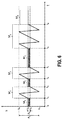
図7の動作パターンは、放出モードM4の点でのみ、図6の動作グラフと異なる。図6の第2の動作モードM2のようにシンプルな鋸歯状の上下動作に代わって、プランジャ21は一定時間、最上位置S4を保持する。この時間の間、ドージング材料はプランジャ21の前に流れることができる。この後にプランジャ21の放出方向Eの非常に急速な動作が続く。再度、プランジャ21は、一定時間、放出方向の最下位置S3を保持する。この時間の間、後続のプランジャ21の後退方向の動作でドージング材料の放出が遅れることを避けるために、ドージング材料の動きがいくらか確認される。
The operation pattern of FIG. 7 differs from the operation graph of FIG. 6 only in the discharge mode M 4 . Instead of a simple serrated up / down operation as in the second operation mode M 2 in FIG. 6, the
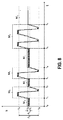
さらに図8の動作パターンは、放出モードM5の点で、図7の動作グラフと異なる。ここで、第1の動作モードM1における動作パターン、すなわちプランジャ21の微小振動動作は、図7に示される動作モードの動作パターン上の放出動作の間、重ね合わせられる。これは、極めて細かい鋸歯状の動作が停止したときに、ドージング材料の粘度が比較的急速に増す場合に好都合である。動作パターンを重ね合わせることは、ドージング材料の粘度を持続的に低減することを確実にする。
Further, the operation pattern of FIG. 8 is different from the operation graph of FIG. 7 in the point of the discharge mode M 5 . Here, the operation pattern in the first operation mode M 1 , that is, the minute vibration operation of the
図9は、例えば、ドージング材料のそれぞれのドットを並んで近くに置くことによって、「ロープ」すなわち均一の厚さの連続した帯を適用するのが適した動作パターンを示している。たとえ、各滴下について、プランジャ21のストロークの長さが同じであっても、ドージング材料によっては、最初と最後の滴下が中間の滴下より大きくなる場合がある。この場合に、ストローク長さのみが異なる、異なる放出モードM2、M6を適用することは好都合であり得る。例えば、最初と最後の滴下に関して、中間の滴下より短いストロークを有する動作モードM2を選択することができる。
FIG. 9 shows an operational pattern that is suitable for applying a “rope” or a continuous strip of uniform thickness, for example by placing each dot of dosing material close together. Even if the length of the stroke of the
これらの例は、さまざまな動作モードの特定のパラメーターおよびその動作モードのシーケンスを、処理される投与材料のそれぞれに、およびドージング割り当てに正確に適合させることが、本発明により理想的に可能であることを明確に示している。上記で詳述したドージングシステムまたはノズルおよびアクチュエータシステムの構成要素は、単なる例示であり、様々な方法で当業者による変更が可能であり、その特徴は本発明の範囲を逸脱することなく新たな方法で組み合わせることが可能であることを再度指摘する。 These examples are ideally possible according to the invention to accurately adapt the specific parameters of the various modes of operation and their sequence of modes of operation to each of the dosing materials being processed and to the dosing assignment. This is clearly shown. The components of the dosing system or nozzle and actuator system detailed above are merely exemplary and can be modified by those skilled in the art in various ways, the features of which are new ways without departing from the scope of the present invention. It is pointed out again that they can be combined.
明確さのために、本出願の全体にわたって、「a」または「an」の使用は、複数を排除するものではない。さらに「ユニット」は、空間的に分離している1つまたは2つ以上の構成要素も含んでよい。 For clarity, the use of “a” or “an” throughout this application does not exclude a plurality. A “unit” may also include one or more components that are spatially separated.
1 ノズル
3 ドージングシステム
5 ドージング材料容器
7 ドージング材料リザーバ
9 接続スクリュー
11 接続ストッパー
13 供給ライン
15 供給口
17 ドージング材料収集キャビティ
19 出口開口
21 閉鎖エレメント(プランジャ)
23a 第1の圧電アクチュエータ
23b 第2の圧電アクチュエータ
25 アクチュエータチャンバ
27 スペーサー
29 スペーサー調整スクリュー
31 接触端子
33 接触端子
35 ハウジング
37 第1のハウジング部
39 第2のハウジング部
41 保持スクリュー
43 ばね
45 シール(リングシール)
47 ガイドエレメント
49 接続エレメント
51 接続エレメント
52 キャビティ
53 ギャップ
55 閉鎖通路
58 保持手段
59 アクチュエータ領域
61 アクチュエータシステム
63 電子制御装置
A1、A2 振幅(移動)
E 放出方向
M1 動作モード(液体保持モード)
M2 動作モード(放出モード)
M3 動作モード(静止)
M4 動作モード(放出モード)
M5 動作モード(放出モード)
M6 動作モード(放出モード)
R 後退方向
S 経路
S1 外面
s1、s2、s3、s4 位置
S2 内面
SS1 第1の制御信号
SS2 第2の制御信号
t 時間
t0、t1、t2、t3、t4、t5、t6 時間段階
WR 作用方向軸
X (中心)軸
Y 領域
DESCRIPTION OF
23a First
47 Guide element 49
E Release direction M 1 operation mode (liquid holding mode)
M 2 operating mode (release mode)
M 3 operation modes (still)
M 4 mode of operation (release mode)
M 5 mode of operation (release mode)
M 6 operation mode (release mode)
R backward direction S path S 1 outer surface s 1 , s 2 , s 3 , s 4 position S 2 inner surface SS 1 first control signal SS 2 second control signal t time t 0 , t 1 , t 2 , t 3 , T 4 , t 5 , t 6 time stage WR action direction axis X (center) axis Y region
Claims (16)
前記ノズル(1)領域に閉鎖エレメント(21)を可動に配置するステップ、および
前記閉鎖エレメント(21)を、伸長可能な少なくとも2つの圧電アクチュエータ(23a、23b)に結合するステップを少なくとも含み、
前記圧電アクチュエータ(23a、23b)は、第1の圧電アクチュエータ(23a)が動作中に伸長すると前記閉鎖エレメント(21)を後退方向(R)に動かし、第2の圧電アクチュエータ(23b)が動作中に伸長すると前記閉鎖エレメント(21)を放出方向(E)に動かすように配置され、前記閉鎖エレメント(21)と結合されるドージングシステム(3)の製造方法。 Providing a nozzle (1) with an outlet opening (19);
Movably disposing a closure element (21) in the nozzle (1) region and coupling the closure element (21) to at least two extendable piezoelectric actuators (23a, 23b);
When the first piezoelectric actuator (23a) extends during operation, the piezoelectric actuator (23a, 23b) moves the closing element (21) in the backward direction (R), and the second piezoelectric actuator (23b) operates. Method of manufacturing a dosing system (3) arranged to move the closure element (21) in the discharge direction (E) when extended inward and coupled with the closure element (21).
Applications Claiming Priority (3)
| Application Number | Priority Date | Filing Date | Title |
|---|---|---|---|
| DE102012109123.4A DE102012109123A1 (en) | 2012-09-27 | 2012-09-27 | Dosing system, dosing process and manufacturing process |
| DE102012109123.4 | 2012-09-27 | ||
| PCT/EP2013/067490 WO2014048643A1 (en) | 2012-09-27 | 2013-08-22 | Dosing system, dosing method and production method |
Publications (3)
| Publication Number | Publication Date |
|---|---|
| JP2015535735A JP2015535735A (en) | 2015-12-17 |
| JP2015535735A5 JP2015535735A5 (en) | 2016-05-12 |
| JP6173467B2 true JP6173467B2 (en) | 2017-08-02 |
Family
ID=49115486
Family Applications (1)
| Application Number | Title | Priority Date | Filing Date |
|---|---|---|---|
| JP2015533496A Active JP6173467B2 (en) | 2012-09-27 | 2013-08-22 | Dosing system, dosing method, and manufacturing method |
Country Status (7)
| Country | Link |
|---|---|
| US (1) | US9457935B2 (en) |
| EP (1) | EP2900390B1 (en) |
| JP (1) | JP6173467B2 (en) |
| KR (1) | KR102061170B1 (en) |
| CN (1) | CN104684656B (en) |
| DE (1) | DE102012109123A1 (en) |
| WO (1) | WO2014048643A1 (en) |
Cited By (1)
| Publication number | Priority date | Publication date | Assignee | Title |
|---|---|---|---|---|
| JP7373779B1 (en) | 2022-08-31 | 2023-11-06 | 株式会社 ホーペック | Tents and how to set them up |
Families Citing this family (25)
| Publication number | Priority date | Publication date | Assignee | Title |
|---|---|---|---|---|
| KR101614312B1 (en) * | 2014-11-18 | 2016-04-22 | 주식회사 프로텍 | Piezoelectric Dispenser and Method for Compensating Stroke of the Same |
| US10090453B2 (en) | 2015-05-22 | 2018-10-02 | Nordson Corporation | Piezoelectric jetting system and method |
| KR102494267B1 (en) * | 2015-05-22 | 2023-02-02 | 노드슨 코포레이션 | Piezoelectric injection system and method with amplification mechanism |
| US10022744B2 (en) | 2015-05-22 | 2018-07-17 | Nordson Corporation | Piezoelectric jetting system with quick release jetting valve |
| CN105327835B (en) * | 2015-12-07 | 2017-12-01 | 常州高凯精密机械有限公司 | A kind of piezoelectricity tandem plunger ejecting adhesive dispenser |
| CN105944847B (en) * | 2016-06-21 | 2018-06-01 | 北京航空航天大学 | Reed-type hydrodynamic ultrasonic wave gas-liquid-solid multiphase mixer |
| JP6778426B2 (en) * | 2016-09-20 | 2020-11-04 | 武蔵エンジニアリング株式会社 | Liquid material discharge device |
| KR102402459B1 (en) * | 2016-10-18 | 2022-05-25 | 마이크로닉 아베 | Method and apparatus for dispensing a viscous medium using an impact device |
| DE102016014952A1 (en) | 2016-12-14 | 2018-06-14 | Dürr Systems Ag | Coating device for coating components |
| DE102016014948A1 (en) | 2016-12-14 | 2018-06-14 | Dürr Systems Ag | Printhead and related operating procedures |
| DE102016014947A1 (en) | 2016-12-14 | 2018-06-14 | Dürr Systems Ag | Printhead for applying a coating agent |
| DE102016014951A1 (en) | 2016-12-14 | 2018-06-14 | Dürr Systems Ag | Coating device and associated operating method |
| DE102016014919A1 (en) | 2016-12-14 | 2018-06-14 | Dürr Systems Ag | Application device and method for applying a coating agent |
| DE102016014956A1 (en) | 2016-12-14 | 2018-06-14 | Dürr Systems Ag | Coating device and associated operating method |
| DE102016014943A1 (en) | 2016-12-14 | 2018-06-14 | Dürr Systems Ag | Printhead with tempering device |
| DE102016014944A1 (en) | 2016-12-14 | 2018-06-14 | Dürr Systems Ag | Coating method and corresponding coating device |
| DE102016014955A1 (en) | 2016-12-14 | 2018-06-14 | Dürr Systems Ag | Coating device and corresponding coating method |
| DE102016014946A1 (en) | 2016-12-14 | 2018-06-14 | Dürr Systems Ag | Printhead for applying a coating agent to a component |
| EP3335805B1 (en) | 2016-12-19 | 2019-04-03 | Nordson Corporation | Piezoelectric jetting dispenser |
| US11433418B2 (en) * | 2017-04-21 | 2022-09-06 | Nordson Corporation | Dispensing system |
| EP3651992A1 (en) * | 2017-07-12 | 2020-05-20 | Mycronic Ab | Jetting devices with acoustic transducers and methods of controlling same |
| DE102018001048A1 (en) * | 2018-02-09 | 2019-08-14 | Atlas Copco Ias Gmbh | metering valve |
| EP3769855B1 (en) * | 2018-03-20 | 2024-03-13 | Musashi Engineering, Inc. | Liquid material ejecting apparatus |
| US11648197B2 (en) | 2018-06-28 | 2023-05-16 | Arx, Llc | Dispensing method for producing dissolvable unit dose film constructs |
| DE102019121679A1 (en) * | 2019-08-12 | 2021-02-18 | Vermes Microdispensing GmbH | Dosing system with adjustable actuator |
Family Cites Families (39)
| Publication number | Priority date | Publication date | Assignee | Title |
|---|---|---|---|---|
| DE1400725A1 (en) | 1963-03-01 | 1968-10-17 | August Moralt Holzindustrie | Nozzle for atomizing liquids with thixotropic properties |
| DE2904861C3 (en) * | 1979-02-09 | 1981-08-06 | Philips Patentverwaltung Gmbh, 2000 Hamburg | Piezoelectric liquid atomizer |
| DE3010178C2 (en) | 1980-03-17 | 1985-10-03 | Kraftwerk Union AG, 4330 Mülheim | Slotted nozzle equipped with a quick-acting valve to induce pulsed gas flows |
| DE3035315C2 (en) | 1980-09-18 | 1984-07-12 | Erwin Sick Gmbh Optik-Elektronik, 7808 Waldkirch | Piezoelectric light deflection device |
| JPH067944B2 (en) | 1985-10-18 | 1994-02-02 | 富士写真フイルム株式会社 | Application method |
| US5094399A (en) | 1988-09-26 | 1992-03-10 | Technadyne Engineering Corporation | Application of thermal-cure materials |
| US5516043A (en) * | 1994-06-30 | 1996-05-14 | Misonix Inc. | Ultrasonic atomizing device |
| US5536531A (en) | 1994-07-26 | 1996-07-16 | Minnesota Mining And Manufacturing Company | Applicator for shear thinning viscous coating materials |
| DE19521478C1 (en) | 1995-06-13 | 1996-09-12 | Itw Dynatec Gmbh Klebetechnik | Application head for controlled issue of flowing media |
| DE19531652A1 (en) | 1995-08-29 | 1997-05-07 | Bosch Gmbh Robert | Fuel injection valve for internal combustion engines |
| US5819983A (en) * | 1995-11-22 | 1998-10-13 | Camelot Sysems, Inc. | Liquid dispensing system with sealing augering screw and method for dispensing |
| SE513527C2 (en) | 1998-06-11 | 2000-09-25 | Mydata Automation Ab | Device and method for ejecting small droplets |
| DE19918976A1 (en) | 1999-04-27 | 2000-11-02 | Bosch Gmbh Robert | Fuel injector and method for actuating it |
| US6589791B1 (en) | 1999-05-20 | 2003-07-08 | Cartesian Technologies, Inc. | State-variable control system |
| JP2001046940A (en) | 1999-08-06 | 2001-02-20 | Juki Corp | Coater |
| US6345771B1 (en) | 2000-06-30 | 2002-02-12 | Siemens Automotive Corporation | Multiple stack piezoelectric actuator for a fuel injector |
| JP2002021715A (en) | 2000-07-10 | 2002-01-23 | Matsushita Electric Ind Co Ltd | Device and method for feeding fluid |
| DE10050469B4 (en) | 2000-10-12 | 2006-07-20 | Rolf Heiden | Method and device for sealing a gap |
| JP4681126B2 (en) | 2000-12-13 | 2011-05-11 | 富士機械製造株式会社 | High viscosity fluid application equipment |
| JP2003003952A (en) * | 2001-06-22 | 2003-01-08 | Noiberuku Kk | Fluid discharge device |
| JP4077624B2 (en) * | 2001-07-09 | 2008-04-16 | 松下電器産業株式会社 | Fluid ejection device and fluid ejection method |
| SE0202247D0 (en) | 2002-07-18 | 2002-07-18 | Mydata Automation Ab | Jetting device and method at a jetting device |
| JP2004105799A (en) * | 2002-09-13 | 2004-04-08 | Matsushita Electric Ind Co Ltd | Fluid discharging apparatus |
| KR20040029276A (en) | 2002-09-30 | 2004-04-06 | 마츠시타 덴끼 산교 가부시키가이샤 | Method and device for discharging fluid |
| US6811093B2 (en) | 2002-10-17 | 2004-11-02 | Tecumseh Products Company | Piezoelectric actuated fuel injectors |
| DE10305389A1 (en) | 2003-02-11 | 2004-08-19 | Daimlerchrysler Ag | Fuel injection valve for direct fuel injection into an internal combustion engine's combustion chamber has piezoelectric or magnetostrictive actuators |
| DE10345840A1 (en) | 2003-09-30 | 2005-04-14 | Sca Schucker Gmbh & Co. Kg | Device for applying a fluid to the surface of a workpiece used in vehicle construction and in furniture manufacture comprises a feed channel which communicates with a return channel via a distribution path arranged within a shaft |
| US7694855B2 (en) * | 2004-04-23 | 2010-04-13 | Nordson Corporation | Dispenser having a pivoting actuator assembly |
| WO2006078018A1 (en) | 2005-01-24 | 2006-07-27 | Neuberg Company Limited | Liquid discharging device |
| CN101858438A (en) | 2005-04-04 | 2010-10-13 | 诺信公司 | Dispenser and correlation technique with replaceable actuators |
| US20070075286A1 (en) | 2005-10-04 | 2007-04-05 | Par Technologies, Llc | Piezoelectric valves drive |
| US20070129681A1 (en) * | 2005-11-01 | 2007-06-07 | Par Technologies, Llc | Piezoelectric actuation of piston within dispensing chamber |
| EP1816341B1 (en) | 2006-02-03 | 2011-04-27 | Continental Automotive GmbH | Actuator device for an injector and injector |
| US7980197B2 (en) | 2006-11-03 | 2011-07-19 | Illinois Tool Works, Inc. | Method and apparatus for dispensing a viscous material on a substrate |
| GB2451833A (en) | 2007-08-13 | 2009-02-18 | Bespak Plc | Electrically actuated dose counter for dispensing apparatus |
| CN201316685Y (en) | 2008-11-24 | 2009-09-30 | 深圳市创唯星自动化设备有限公司 | Structure controlling flow of glue stuff in nozzle |
| EP2552512A1 (en) * | 2010-04-01 | 2013-02-06 | Alpimed Sàrl | Inductively operated fluid dispensing device |
| DE102010015591B3 (en) | 2010-04-19 | 2011-11-17 | Ucon Ag Containersysteme Kg | metering |
| DE102010039165A1 (en) | 2010-08-10 | 2012-02-16 | Robert Bosch Gmbh | Positioning device for use in combustion engine of vehicle, has piezoelectric actuator placing position element in one direction and another piezoelectric actuator placing position element in another direction |
-
2012
- 2012-09-27 DE DE102012109123.4A patent/DE102012109123A1/en not_active Ceased
-
2013
- 2013-08-22 KR KR1020157007759A patent/KR102061170B1/en active IP Right Grant
- 2013-08-22 US US14/432,134 patent/US9457935B2/en active Active
- 2013-08-22 WO PCT/EP2013/067490 patent/WO2014048643A1/en active Application Filing
- 2013-08-22 EP EP13756845.7A patent/EP2900390B1/en active Active
- 2013-08-22 CN CN201380050879.4A patent/CN104684656B/en active Active
- 2013-08-22 JP JP2015533496A patent/JP6173467B2/en active Active
Cited By (1)
| Publication number | Priority date | Publication date | Assignee | Title |
|---|---|---|---|---|
| JP7373779B1 (en) | 2022-08-31 | 2023-11-06 | 株式会社 ホーペック | Tents and how to set them up |
Also Published As
| Publication number | Publication date |
|---|---|
| EP2900390B1 (en) | 2020-07-15 |
| US9457935B2 (en) | 2016-10-04 |
| JP2015535735A (en) | 2015-12-17 |
| CN104684656B (en) | 2017-06-09 |
| KR20150059749A (en) | 2015-06-02 |
| DE102012109123A1 (en) | 2014-03-27 |
| CN104684656A (en) | 2015-06-03 |
| WO2014048643A1 (en) | 2014-04-03 |
| EP2900390A1 (en) | 2015-08-05 |
| US20150274371A1 (en) | 2015-10-01 |
| KR102061170B1 (en) | 2019-12-31 |
Similar Documents
| Publication | Publication Date | Title |
|---|---|---|
| JP6173467B2 (en) | Dosing system, dosing method, and manufacturing method | |
| JP6454286B2 (en) | Metering valve and metering method | |
| JP6173466B2 (en) | Dosing system, dosing method, and manufacturing method | |
| KR102012303B1 (en) | Liquid material discharge apparatus and method | |
| US8757511B2 (en) | Viscous non-contact jetting method and apparatus | |
| KR101904135B1 (en) | Dosing system and dosing method | |
| EP2732883B1 (en) | Droplet discharge device and method | |
| KR102046840B1 (en) | Liquid material discharge device and discharge method | |
| US10221060B2 (en) | Microvolume-liquid dispensing method and microvolume-liquid dispenser | |
| JP2009113025A (en) | Droplet ejection device for highly viscous liquid | |
| CN102574395A (en) | Multichannel - printhead or dosing head | |
| US20180009594A1 (en) | Plunger for dispenser, dispenser, and method for dispensing liquid material | |
| EP3448684B1 (en) | Industrial printhead | |
| JP2022510639A (en) | Dosing system and how to control the dosing system | |
| JP2013139745A (en) | Viscous non-contact injection method and device | |
| US10682664B2 (en) | Microvolume-liquid application method and microvolume-liquid dispenser | |
| JP5947865B2 (en) | Valve for metering of filled and pasty media | |
| JP6958292B2 (en) | Liquid discharge device |
Legal Events
| Date | Code | Title | Description |
|---|---|---|---|
| A521 | Request for written amendment filed |
Free format text: JAPANESE INTERMEDIATE CODE: A523 Effective date: 20160310 |
|
| A621 | Written request for application examination |
Free format text: JAPANESE INTERMEDIATE CODE: A621 Effective date: 20160310 |
|
| A131 | Notification of reasons for refusal |
Free format text: JAPANESE INTERMEDIATE CODE: A131 Effective date: 20170307 |
|
| A521 | Request for written amendment filed |
Free format text: JAPANESE INTERMEDIATE CODE: A523 Effective date: 20170605 |
|
| TRDD | Decision of grant or rejection written | ||
| A01 | Written decision to grant a patent or to grant a registration (utility model) |
Free format text: JAPANESE INTERMEDIATE CODE: A01 Effective date: 20170620 |
|
| A61 | First payment of annual fees (during grant procedure) |
Free format text: JAPANESE INTERMEDIATE CODE: A61 Effective date: 20170704 |
|
| R150 | Certificate of patent or registration of utility model |
Ref document number: 6173467 Country of ref document: JP Free format text: JAPANESE INTERMEDIATE CODE: R150 |
|
| R250 | Receipt of annual fees |
Free format text: JAPANESE INTERMEDIATE CODE: R250 |
|
| R250 | Receipt of annual fees |
Free format text: JAPANESE INTERMEDIATE CODE: R250 |
|
| R250 | Receipt of annual fees |
Free format text: JAPANESE INTERMEDIATE CODE: R250 |
|
| S531 | Written request for registration of change of domicile |
Free format text: JAPANESE INTERMEDIATE CODE: R313531 |
|
| R350 | Written notification of registration of transfer |
Free format text: JAPANESE INTERMEDIATE CODE: R350 |
|
| R250 | Receipt of annual fees |
Free format text: JAPANESE INTERMEDIATE CODE: R250 |