JP6168564B2 - Method and power generation system for supplying electrical energy from a distributed energy source - Google Patents
Method and power generation system for supplying electrical energy from a distributed energy source Download PDFInfo
- Publication number
- JP6168564B2 JP6168564B2 JP2014553296A JP2014553296A JP6168564B2 JP 6168564 B2 JP6168564 B2 JP 6168564B2 JP 2014553296 A JP2014553296 A JP 2014553296A JP 2014553296 A JP2014553296 A JP 2014553296A JP 6168564 B2 JP6168564 B2 JP 6168564B2
- Authority
- JP
- Japan
- Prior art keywords
- demand
- electrical energy
- limit
- period
- storage system
- Prior art date
- Legal status (The legal status is an assumption and is not a legal conclusion. Google has not performed a legal analysis and makes no representation as to the accuracy of the status listed.)
- Active
Links
Images
Classifications
-
- H—ELECTRICITY
- H02—GENERATION; CONVERSION OR DISTRIBUTION OF ELECTRIC POWER
- H02J—ELECTRIC POWER NETWORKS; CIRCUIT ARRANGEMENTS OR SYSTEMS FOR SUPPLYING OR DISTRIBUTING ELECTRIC POWER; SYSTEMS FOR STORING ELECTRIC ENERGY
- H02J3/00—Circuit arrangements for AC mains or AC distribution networks
- H02J3/28—Arrangements for balancing of the load in networks by storage of energy
- H02J3/32—Arrangements for balancing of the load in networks by storage of energy using batteries or super capacitors with converting means
-
- H—ELECTRICITY
- H02—GENERATION; CONVERSION OR DISTRIBUTION OF ELECTRIC POWER
- H02J—ELECTRIC POWER NETWORKS; CIRCUIT ARRANGEMENTS OR SYSTEMS FOR SUPPLYING OR DISTRIBUTING ELECTRIC POWER; SYSTEMS FOR STORING ELECTRIC ENERGY
- H02J3/00—Circuit arrangements for AC mains or AC distribution networks
- H02J3/38—Arrangements for feeding a single network from two or more generators or sources in parallel; Arrangements for feeding already energised networks from additional generators or sources in parallel
- H02J3/381—Dispersed generators
-
- H—ELECTRICITY
- H02—GENERATION; CONVERSION OR DISTRIBUTION OF ELECTRIC POWER
- H02J—ELECTRIC POWER NETWORKS; CIRCUIT ARRANGEMENTS OR SYSTEMS FOR SUPPLYING OR DISTRIBUTING ELECTRIC POWER; SYSTEMS FOR STORING ELECTRIC ENERGY
- H02J2101/00—Supply or distribution of decentralised, dispersed or local electric power generation
- H02J2101/10—Dispersed power generation using fossil fuels, e.g. diesel generators
-
- H—ELECTRICITY
- H02—GENERATION; CONVERSION OR DISTRIBUTION OF ELECTRIC POWER
- H02J—ELECTRIC POWER NETWORKS; CIRCUIT ARRANGEMENTS OR SYSTEMS FOR SUPPLYING OR DISTRIBUTING ELECTRIC POWER; SYSTEMS FOR STORING ELECTRIC ENERGY
- H02J2101/00—Supply or distribution of decentralised, dispersed or local electric power generation
- H02J2101/20—Dispersed power generation using renewable energy sources
- H02J2101/22—Solar energy
- H02J2101/24—Photovoltaics
-
- H—ELECTRICITY
- H02—GENERATION; CONVERSION OR DISTRIBUTION OF ELECTRIC POWER
- H02J—ELECTRIC POWER NETWORKS; CIRCUIT ARRANGEMENTS OR SYSTEMS FOR SUPPLYING OR DISTRIBUTING ELECTRIC POWER; SYSTEMS FOR STORING ELECTRIC ENERGY
- H02J2105/00—Networks for supplying or distributing electric power characterised by their spatial reach or by the load
- H02J2105/10—Local stationary networks having a local or delimited stationary reach
- H02J2105/12—Local stationary networks having a local or delimited stationary reach supplying households or buildings
-
- H—ELECTRICITY
- H02—GENERATION; CONVERSION OR DISTRIBUTION OF ELECTRIC POWER
- H02J—ELECTRIC POWER NETWORKS; CIRCUIT ARRANGEMENTS OR SYSTEMS FOR SUPPLYING OR DISTRIBUTING ELECTRIC POWER; SYSTEMS FOR STORING ELECTRIC ENERGY
- H02J2105/00—Networks for supplying or distributing electric power characterised by their spatial reach or by the load
- H02J2105/50—Networks for supplying or distributing electric power characterised by their spatial reach or by the load for selectively controlling the operation of the loads
- H02J2105/54—Networks for supplying or distributing electric power characterised by their spatial reach or by the load for selectively controlling the operation of the loads according to a non-electrical condition, e.g. temperature
- H02J2105/55—Networks for supplying or distributing electric power characterised by their spatial reach or by the load for selectively controlling the operation of the loads according to a non-electrical condition, e.g. temperature according to an economic condition, e.g. tariff-based load management
-
- H—ELECTRICITY
- H02—GENERATION; CONVERSION OR DISTRIBUTION OF ELECTRIC POWER
- H02J—ELECTRIC POWER NETWORKS; CIRCUIT ARRANGEMENTS OR SYSTEMS FOR SUPPLYING OR DISTRIBUTING ELECTRIC POWER; SYSTEMS FOR STORING ELECTRIC ENERGY
- H02J3/00—Circuit arrangements for AC mains or AC distribution networks
- H02J3/12—Arrangements for adjusting voltage in AC networks by changing a characteristic of the network load
- H02J3/14—Arrangements for adjusting voltage in AC networks by changing a characteristic of the network load by switching loads on to, or off from, the networks, e.g. progressively balanced loading
-
- Y—GENERAL TAGGING OF NEW TECHNOLOGICAL DEVELOPMENTS; GENERAL TAGGING OF CROSS-SECTIONAL TECHNOLOGIES SPANNING OVER SEVERAL SECTIONS OF THE IPC; TECHNICAL SUBJECTS COVERED BY FORMER USPC CROSS-REFERENCE ART COLLECTIONS [XRACs] AND DIGESTS
- Y02—TECHNOLOGIES OR APPLICATIONS FOR MITIGATION OR ADAPTATION AGAINST CLIMATE CHANGE
- Y02B—CLIMATE CHANGE MITIGATION TECHNOLOGIES RELATED TO BUILDINGS, e.g. HOUSING, HOUSE APPLIANCES OR RELATED END-USER APPLICATIONS
- Y02B70/00—Technologies for an efficient end-user side electric power management and consumption
- Y02B70/30—Systems integrating technologies related to power network operation and communication or information technologies for improving the carbon footprint of the management of residential or tertiary loads, i.e. smart grids as climate change mitigation technology in the buildings sector, including also the last stages of power distribution and the control, monitoring or operating management systems at local level
- Y02B70/3225—Demand response systems, e.g. load shedding, peak shaving
-
- Y—GENERAL TAGGING OF NEW TECHNOLOGICAL DEVELOPMENTS; GENERAL TAGGING OF CROSS-SECTIONAL TECHNOLOGIES SPANNING OVER SEVERAL SECTIONS OF THE IPC; TECHNICAL SUBJECTS COVERED BY FORMER USPC CROSS-REFERENCE ART COLLECTIONS [XRACs] AND DIGESTS
- Y02—TECHNOLOGIES OR APPLICATIONS FOR MITIGATION OR ADAPTATION AGAINST CLIMATE CHANGE
- Y02E—REDUCTION OF GREENHOUSE GAS [GHG] EMISSIONS, RELATED TO ENERGY GENERATION, TRANSMISSION OR DISTRIBUTION
- Y02E10/00—Energy generation through renewable energy sources
- Y02E10/50—Photovoltaic [PV] energy
- Y02E10/56—Power conversion systems, e.g. maximum power point trackers
-
- Y—GENERAL TAGGING OF NEW TECHNOLOGICAL DEVELOPMENTS; GENERAL TAGGING OF CROSS-SECTIONAL TECHNOLOGIES SPANNING OVER SEVERAL SECTIONS OF THE IPC; TECHNICAL SUBJECTS COVERED BY FORMER USPC CROSS-REFERENCE ART COLLECTIONS [XRACs] AND DIGESTS
- Y02—TECHNOLOGIES OR APPLICATIONS FOR MITIGATION OR ADAPTATION AGAINST CLIMATE CHANGE
- Y02E—REDUCTION OF GREENHOUSE GAS [GHG] EMISSIONS, RELATED TO ENERGY GENERATION, TRANSMISSION OR DISTRIBUTION
- Y02E70/00—Other energy conversion or management systems reducing GHG emissions
- Y02E70/30—Systems combining energy storage with energy generation of non-fossil origin
-
- Y—GENERAL TAGGING OF NEW TECHNOLOGICAL DEVELOPMENTS; GENERAL TAGGING OF CROSS-SECTIONAL TECHNOLOGIES SPANNING OVER SEVERAL SECTIONS OF THE IPC; TECHNICAL SUBJECTS COVERED BY FORMER USPC CROSS-REFERENCE ART COLLECTIONS [XRACs] AND DIGESTS
- Y04—INFORMATION OR COMMUNICATION TECHNOLOGIES HAVING AN IMPACT ON OTHER TECHNOLOGY AREAS
- Y04S—SYSTEMS INTEGRATING TECHNOLOGIES RELATED TO POWER NETWORK OPERATION, COMMUNICATION OR INFORMATION TECHNOLOGIES FOR IMPROVING THE ELECTRICAL POWER GENERATION, TRANSMISSION, DISTRIBUTION, MANAGEMENT OR USAGE, i.e. SMART GRIDS
- Y04S20/00—Management or operation of end-user stationary applications or the last stages of power distribution; Controlling, monitoring or operating thereof
- Y04S20/20—End-user application control systems
- Y04S20/222—Demand response systems, e.g. load shedding, peak shaving
-
- Y—GENERAL TAGGING OF NEW TECHNOLOGICAL DEVELOPMENTS; GENERAL TAGGING OF CROSS-SECTIONAL TECHNOLOGIES SPANNING OVER SEVERAL SECTIONS OF THE IPC; TECHNICAL SUBJECTS COVERED BY FORMER USPC CROSS-REFERENCE ART COLLECTIONS [XRACs] AND DIGESTS
- Y04—INFORMATION OR COMMUNICATION TECHNOLOGIES HAVING AN IMPACT ON OTHER TECHNOLOGY AREAS
- Y04S—SYSTEMS INTEGRATING TECHNOLOGIES RELATED TO POWER NETWORK OPERATION, COMMUNICATION OR INFORMATION TECHNOLOGIES FOR IMPROVING THE ELECTRICAL POWER GENERATION, TRANSMISSION, DISTRIBUTION, MANAGEMENT OR USAGE, i.e. SMART GRIDS
- Y04S50/00—Market activities related to the operation of systems integrating technologies related to power network operation or related to communication or information technologies
- Y04S50/10—Energy trading, including energy flowing from end-user application to grid
Landscapes
- Engineering & Computer Science (AREA)
- Power Engineering (AREA)
- Supply And Distribution Of Alternating Current (AREA)
- Remote Monitoring And Control Of Power-Distribution Networks (AREA)
- Charge And Discharge Circuits For Batteries Or The Like (AREA)
- Feedback Control In General (AREA)
- Testing And Monitoring For Control Systems (AREA)
Description
(関連出願の相互参照) 本出願は、2012年1月20日出願の米国仮出願第61/589,158号の利益を主張し、その全体を参照することにより本明細書に組み込む。 CROSS REFERENCE TO RELATED APPLICATIONS This application claims the benefit of US Provisional Application No. 61 / 589,158, filed Jan. 20, 2012, which is incorporated herein by reference in its entirety.
本明細書に記載する主題の実施形態は、概して光起電システムに関する。より具体的には、主題の実施形態は、分散型エネルギー源から電気エネルギーを供給することに関する。 Embodiments of the subject matter described herein generally relate to photovoltaic systems. More specifically, the subject embodiments relate to supplying electrical energy from a distributed energy source.
電気供給者は、また「電気事業者」とも称され、消費される電気エネルギー量だけではなくまた、電気エネルギーが消費される期間、及び特定の時間間隔にわたる、エネルギー消費の平均電力需要レベルに基づいてその顧客に課金する。より具体的に、電気事業者は、特定の期間における電力需要へのサーチャージである、需要電力料金を課金し得る。電気代を下げるために、光起電システムが利用され得るが、需要電力料金を低下させるために、長い期間にわたり、貯蔵された電気エネルギーをどのように供給することが最良かを判断するために、限定的な努力しかなされてこなかった。 An electricity supplier, also called an “electric utility”, is based not only on the amount of electrical energy consumed, but also on the period of time that the electrical energy is consumed and the average power demand level of energy consumption over a specific time interval. To charge the customer. More specifically, an electric utility may charge a demand power charge, which is a surcharge for power demand in a specific period. Photovoltaic systems can be used to lower electricity bills, but to determine how best to supply stored electrical energy over a long period of time in order to reduce electricity bills Only limited efforts have been made.
一実施形態において、エネルギー貯蔵システムから電気エネルギーを供給する方法は、設備負荷の電気エネルギー需要をモニタリングすることを含む。需要期間の需要限界が設定される。設備負荷の電気エネルギー需要が、需要期間中の需要限界と比較される。設備負荷の電気エネルギー需要が需要限界よりも低いと予測されるという判断に応じて、エネルギー貯蔵システムが、需要期間における残余の時間よりも長い期間にわたり、放電限界において電気エネルギーを供給することができるかどうかが判定される。エネルギー貯蔵システムが、需要期間の残余の時間よりも長い期間にわたり、放電限界において、電気エネルギーを供給することができるかどうかの判定に応じて、電気エネルギーがエネルギー貯蔵システムから放電限界において放電される。 In one embodiment, a method of supplying electrical energy from an energy storage system includes monitoring electrical energy demands of equipment loads. A demand limit for the demand period is set. The electrical energy demand of the equipment load is compared with the demand limit during the demand period. In response to the determination that the electrical energy demand of the facility load is expected to be below the demand limit, the energy storage system can supply electrical energy at the discharge limit for a period longer than the remaining time in the demand period It is determined whether or not. Electrical energy is discharged from the energy storage system at the discharge limit in response to determining whether the energy storage system can supply electrical energy at the discharge limit for a period longer than the remainder of the demand period. .
別の実施形態において、発電システムは、エネルギー貯蔵システム、設備負荷に電気エネルギーを供給するように連結された光起電システム、及びエネルギー貯蔵システムから設備負荷への電気エネルギーの放電を制御するように構成された制御システムを含み、制御システムは、電気エネルギーの設備負荷の需要をモニタリングして設備負荷の需要を需要期間の需要限界と比較し、かつ設備負荷における電気エネルギー需要と需要限界の比較に基づく放電率で、電気エネルギーをエネルギー貯蔵システムから放電するように構成されている。 In another embodiment, the power generation system is configured to control the energy storage system, the photovoltaic system coupled to supply electrical energy to the facility load, and the discharge of electrical energy from the energy storage system to the facility load. The system includes a configured control system that monitors the demand for electrical energy equipment load, compares the equipment load demand to the demand limit during the demand period, and compares the electrical energy demand at the equipment load to the demand limit. It is configured to discharge electrical energy from the energy storage system at a discharge rate based on.
別の実施形態において、エネルギー貯蔵システムから電気エネルギーを供給する方法は、設備負荷の電気エネルギー需要をモニタリングすることを含む。第1の需要期間において、設備負荷の第1の電気エネルギー需要が、第1の需要限界と比較される。設備負荷の第1の電気エネルギー需要が、第1の需要限界よりも大きいという予測が判断される。設備負荷の電気エネルギーに対する第1の需要が、第1の需要限界よりも大きくなると予測されるという判断に応じて、電気エネルギーが、エネルギー貯蔵システムから設備負荷へと第1の出力電力で放電される。設備負荷の第1の電気エネルギー需要が、第1の需要限界よりも大きくないという予測が判断される。設備負荷の第1の電気エネルギー需要が、第1の需要限界よりも大きくないことを予測されるとの判断に応じて、エネルギー貯蔵システムは、第1の入力電力で電気エネルギーを充電される。 In another embodiment, a method of supplying electrical energy from an energy storage system includes monitoring electrical energy demands of equipment loads. In the first demand period, the first electrical energy demand of the equipment load is compared with a first demand limit. A prediction is made that the first electrical energy demand for the equipment load is greater than the first demand limit. In response to determining that the first demand for electrical energy of the equipment load is expected to be greater than the first demand limit, the electrical energy is discharged from the energy storage system to the equipment load with the first output power. The A prediction is made that the first electrical energy demand for the equipment load is not greater than the first demand limit. In response to determining that the first electrical energy demand of the facility load is predicted not to be greater than the first demand limit, the energy storage system is charged with electrical energy with the first input power.
本発明のこれら及びその他の特徴は、添付の図面及び特許請求の範囲を含む本開示の全体を読むことにより、当業者には容易に理解されよう。 These and other features of the present invention will be readily apparent to those of ordinary skill in the art upon reading the entirety of this disclosure, including the accompanying drawings and claims.
より完全な本主題の理解は、発明を実施するための形態、及び特許請求の範囲を、以下の図面と併せて考察し、参照することによって導き出すことができ、同様の参照番号は、図面全体を通して同様の要素を指す。 A more complete understanding of the present subject matter can be derived by considering and referring to the following detailed description and claims in conjunction with the following drawings, wherein like reference numerals are used throughout: To refer to similar elements.
本開示では、本発明の実施形態を十分に理解するために、装置、部品及び方法の例など、多数の具体的な詳細を提供している。しかしながら、当業者であれば、本発明はこれらの具体的な詳細のうちの1又は複数を欠いても実施できることは理解されよう。他の例では、本発明の態様を不明瞭にすることを避けるため、周知の詳細については図示又は説明をしていない。 In this disclosure, numerous specific details are provided, such as examples of apparatus, components, and methods, in order to provide a thorough understanding of embodiments of the invention. However, one of ordinary skill in the art appreciates that the invention can be practiced without one or more of these specific details. In other instances, well-known details have not been shown or described in order to avoid obscuring aspects of the invention.
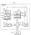
図1は、本発明の実施形態による、発電システムの概略図を示す。図1の実施例において、発電システムは、エネルギー貯蔵システム101、光起電システム102、設備負荷103、電力系統105、及び制御システム110を有する。制御システム110は、エネルギー貯蔵システム101、又は他の分散型エネルギー源から供給される、電気エネルギーを制御するように構成される。図1の実施例において、制御システム110は、顧客の設備100に配設される。顧客の設備100は、例えば、商業用、官公庁用、又は住宅用設備であってもよい。顧客の設備100は、任意により、設備負荷103を制御するように構成された、設備エネルギー管理システム(EMS)114を含み得る。
FIG. 1 shows a schematic diagram of a power generation system according to an embodiment of the present invention. In the embodiment of FIG. 1, the power generation system includes an
図1の実施例において、顧客の設備100は、太陽放射から電気エネルギーを生成するための、光起電システム102を有する。光起電システム102は、他の構成要素の中でもとりわけ、複数の太陽電池106、及び光起電インバータ107を含み得る。太陽電池106は、太陽放射を電気エネルギーに変換する。太陽電池106は、SunPower(商標)Corporation(San Jose California)のものなど、市販の太陽電池であり得る。光起電インバータ107は、太陽電池106によって生成された直流電流(DC)を、電化製品、機械、照明、及び電気エネルギーを消費する他の装置を含み得る、設備負荷103により消費するために好適な交流(AC)へと変換する。光起電システム102は、複数のインバータ107を有してもよいが、図示の明瞭化のために、図1には1つのみが示される。 光起電システム102は、相互接続点(POI)に電気的に接続されてもよく、これは図1の実施例においては、電気設備メータ104を備える。
In the example of FIG. 1,
設備負荷103は、電気事業者の電力系統105、光起電システム102、及びエネルギー貯蔵システム101により供給される電気エネルギーを消費し得る。制御システム110は、エネルギー貯蔵システム101に制御信号を送信して、エネルギー貯蔵システム101に、設備負荷103に放電することにより電気エネルギーを供給するように命令するか、又はエネルギー貯蔵システム101に電力系統105又は光起電システム102からの電気エネルギーを使用して充電するように命令してもよい。光起電システム102は任意により、エネルギー貯蔵システム101と直接接続を有し得る。図1の実施形態において、制御システム110は、設備負荷103からデータを直接受信し、設備負荷103に命令を送信してもよい。他の実施形態において、制御システム110は、EMS114を介して、設備負荷103からデータを受信し、設備負荷103に命令を送信してもよい。
The
エネルギー貯蔵システム101は、電気エネルギー貯蔵装置、又は電気エネルギー発生装置を含み得る。図1の実施形態において、エネルギー貯蔵システム101は、電池及び関連する制御モジュールを有する。一般的に、エネルギー貯蔵システム101は、1又は複数の電気化学的(例えば、電池)、電気的(例えば、コンデンサ、SMES)、機械的(例えば、フライホイール、重力、圧縮空気)、熱的(例えば、冷水、蒸気、躯体)、及び/又は化学的(例えば、天然ガス、水素、ディーゼル)エネルギー貯蔵装置を含み得る。更に、他の実施形態において、エネルギー貯蔵システム101の機能性は、反応性負荷、燃料電池、マイクロタービン、内燃機関など、他の分散型エネルギー源によって満たされる場合がある。これらの他の実施形態において、主な違いは、利用可能な放電又は充電電力に影響する、特定の動作制約である。所望の放電、又は充電電力はまた、異なる信号に変換されなくてはならない場合がある(例えば、充電電力の代わりに、サーモスタットをより低い設定点に変える)。
The
図1の実施例において、制御システム110は、プロセッサ111(例えば、マイクロプロセッサ又は中央演算処理装置)、メモリ112(例えば、ランダムアクセスメモリ、データ貯蔵装置)、及びインターフェース113を含む。制御システム110は、プロセッサ111によって実行される、メモリ112に記憶される、対応するコンピューター可読プログラムコードを有することにより、方法の段階を実行することができる。制御システム110の制御システムはまた、制御機能を実行するために、比例積分微分(PID)コントローラなどの、ハードウェア又はソフトウェアに基づく動作論理を有してもよい。
In the embodiment of FIG. 1, the
インターフェース113は、制御システム110が、エネルギー貯蔵システム101、光起電システム102、及び設備負荷103と通信することを可能にする(例えば、EMS114により)。インターフェース113は、コンピューターネットワークインターフェース、信号ケーブル、無線通信インターフェース、及び/又は装置通信のための他の手段を含み得る。制御システム110の機能性は、実装形態により、1又は複数の装置の間で分散されてもよい。制御システム110の機能性はまた、エネルギー貯蔵システム101、光起電システム102、又はEMS114に組み込まれてもよい。
The
制御システム110は、エネルギー貯蔵システム101から電気エネルギーの供給を制御するように構成されてもよい。一実施形態において、制御システム110は、需要電力料金を下げ、ある期間と別の期間で変化する電気エネルギー量を最大化するように構成される。例えば、制御システム110は、需要電力料金が最高であるピーク期間の間に、エネルギー貯蔵システム101から、電気エネルギーの殆どを供給するように、アービトラージモード(arbitrage mode)で動作するように構成されてもよい。
The
電気事業会社は、請求期間、使用時間、及び間隔に基づいて、消費される電気エネルギーに対して異なる需要電力料金を課してもよい。「請求期間」とは、請求されるパラメータが判断される期間である。例えば、需要電力料金は、1ヶ月ごとの請求期間に基づいて評価されることが多い。請求期間はまた、1年毎であってもよい。料金は請求期間によって異なる場合が多い。例えば、夏の料金は、典型的には冬の料金よりも高い。 An electric utility company may charge different demand electricity charges for consumed electric energy based on billing period, usage time, and interval. “Billing period” is a period during which parameters to be charged are determined. For example, the power demand rate is often evaluated based on a monthly billing period. The billing period may also be every year. Fees often vary depending on the billing period. For example, summer rates are typically higher than winter rates.
使用時間(TOU)は、異なる料金(需要及び/又はエネルギー)が適用される期間である。TOU期間は、請求期間により変化し得る。例示的な夏ピークTOU期間は、5月から10月の、休日を除いた、正午から午後6時である。多くの場合、全て異なる料金で規定された(例えば、ピーク、一部がピーク、ピーク外)いくつかのTOU期間が存在する。例えば、冬の一部ピーク期間(11月〜4月の請求期間)は、異なる期間にわたって規定され、夏の一部ピーク期間とは異なる料金である。いくつかの料金体系は、エネルギーに関してのみ、請求期間内にTOU期間を有し、需要に関しては有さないか、又はその逆である。 Time of use (TOU) is the period during which different charges (demand and / or energy) are applied. The TOU period can vary depending on the billing period. An exemplary summer peak TOU period is from noon to 6 pm, excluding holidays, from May to October. In many cases, there are several TOU periods all defined at different rates (eg, peak, some peak, off peak). For example, the winter partial peak period (November-April billing period) is defined over a different period and is different from the summer partial peak period. Some tariff schemes have a TOU period in the billing period only for energy and not for demand, or vice versa.
「間隔」とは、請求されるエネルギー又は需要が判断される、時間の最小単位である。例として需要電力料金の間隔は15分間である。この例において、請求期間内の特定のTOU期間の需要電力料金は、これらの期間の所定の15分間隔における、最大平均需要に基づく。 An “interval” is the smallest unit of time in which billed energy or demand is determined. As an example, the interval between the demand power charges is 15 minutes. In this example, the power demand rate for specific TOU periods within the billing period is based on the maximum average demand over a predetermined 15 minute interval for these periods.
制御システム110は、特定の請求期間、TOU期間、及び間隔における需要限界を満たすために、エネルギー貯蔵システム101から、電気エネルギーを供給するように構成され得る。需要限界は、電力の単位(例えば、キロワット(kW))で表現されるレベルを有し得る。需要限界は、設備負荷103の電気エネルギーの需要と比較するための基準レベルとして機能し得る。設備負荷103の需要が、需要限界に近づくとき、制御システム110は、設備負荷103の需要が、需要限界と同じレベルにあるように、電気エネルギーをエネルギー貯蔵システム101から十分な放電するように構成され得る。設備負荷103の需要が需要限界よりも低いとき、制御システム110は、エネルギー貯蔵システム101に貯蔵される電気エネルギー量、及び需要期間の残余時間に応じて、需要期間の終了時まで、放電限界において、電気エネルギーをエネルギー貯蔵システム101から放電するように構成され得る。例えば、放電限界は、最大電力であり得る。
The
一実施形態において、制御システム110は、ピーク期間中に、標的ピーク需要限界を満たすように構成される。ピーク需要限界は、過去の負荷、光起電生成、及び将来のこれら上記数量値の予測に基づく場合がある。ピーク需要限界は、設備負荷103の最大予測正味需要から、エネルギー貯蔵システム101の電力定格及び設備100の制御可能な負荷をマイナスしたものに基づく場合がある。設備負荷103の正味需要は、設備負荷103のエネルギー需要から、15分間隔毎の光起電システム102の出力をマイナスしたものであり得る。光起電システム102及びエネルギー貯蔵システム101はその後、標的ピーク需要限界を維持するように操作される。
In one embodiment, the
操作中、標的ピーク需要限界の維持が、所与の一日に需要される制限されたエネルギーを勘案して実行不可能であると予測される場合、ピーク需要限界は、予測に基づき再設定され得る。これは、結果として、エネルギー貯蔵システム101を、より低い電力においてより長い時間稼働させて、需要期間(正味需要が典型的に最も高い)の終了時近くに電気エネルギーが尽きることなく、需要をより少ない量に減らし、したがって需要電力料金に影響しない。エネルギー貯蔵システム101は、計画段階において、貯蔵期間の必要性を低く見積もったことによる、システムエネルギーのいずれかの不足を予防するための、臨時又はバックアップ予備源として主に使用される、制御可能な負荷又は需要源と相互作用してもよい。
During operation, if the maintenance of the target peak demand limit is predicted to be infeasible given the limited energy demanded for a given day, the peak demand limit is reset based on the prediction. obtain. This results in the
需要源の特定の電力/期間曲線は典型的には、装置、ビルの熱容量、及び快適性要件に基づき、設備に特有である。一般的に、設備内で延長される負荷の量は、延長の持続時間に応じて減少し、よってエネルギー貯蔵の比較的短時間の不足(例えば、1時間以下)を管理するために最も適切に使用される。いずれかの所与の一日において、エネルギー貯蔵システム101において余剰エネルギーが利用可能である場合、余剰エネルギーは、例えばエネルギー貯蔵システム101におけるような、全ての残余の利用可能なエネルギーが、アービトラージモードで使用されるように、供給されてもよい。これは、エネルギー貯蔵システム101内のエネルギー量をモニタリングし、ピーク需要期間の時間量が、最大電力におけるエネルギー貯蔵システム101の残余の放電期間より少ないか等しくなったときに、これを最大電力で供給することによって達成され得る。エネルギー貯蔵システム101の再充電はまた、オフピーク需要電力料金の増大を避けるために制限されてもよい。これは、最大再充電需要を制限すること、及び/又は負荷の低い夜間と充電の時間を合わせることによって達成され得る。
The specific power / duration curve of the demand source is typically equipment specific, based on equipment, building heat capacity, and comfort requirements. In general, the amount of load that is extended in the facility decreases with the duration of the extension, and is therefore most appropriate to manage a relatively short shortage of energy storage (eg, less than one hour). used. If any surplus energy is available in the
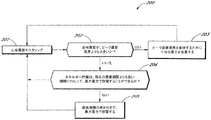
図2は、本発明の実施形態による、エネルギー貯蔵システム101から電気エネルギーを供給する方法200の流れ図を示す。方法200は例示目的でのみ図1に示された構成要素を参照して説明される。
FIG. 2 shows a flow diagram of a
図2の実施例において、方法200は、設備負荷103の正味需要をモニタリングする(段階201)制御システム110を備える。一実施形態において、正味需要は、設備負荷103により必要とされる電気エネルギーの量から、光起電システム102の出力をマイナスしたものである。この実施例において、正味需要は、エネルギー貯蔵システム101がどのように挙動すべきかを判断するために、需要限界と比較されるプロセス変数である。需要限界など、正味需要はまた、電力の単位(この場合はkW)で表現され得る。
In the example of FIG. 2, the
制御システム110は、正味需要を、ピーク需要限界と比較する(段階202)。正味需要がピーク需要限界を超えるものと予測されるとき(例えば、正味需要の現在の傾向に基づき)、制御システム110は、エネルギー貯蔵システム101に、ピーク需要限界を維持し、最大電力より少ないか等しい十分な電力を放電するよう命令する(段階203)。すなわち、正味需要がピーク需要限界よりも大きいとき、エネルギー貯蔵システム101は、正味需要とピーク需要限界との間の差をカバーするために、十分な電力を供給するように命令される。特定の実施例として、正味需要が5000kWであり、ピーク需要限界が4000kWであるとき、制御システム110は、エネルギー貯蔵システム101に、正味需要のレベルと、ピーク需要限界との間の差分(この特定の実施例においては1000kW)を放電させるように命令する。
The
正味需要が、ピーク需要限界を超えないものと予測されるとき、制御システム110は、エネルギー貯蔵システム101が、需要期間の残余の時間よりも長い期間にわたって最大電力で放電できるかどうかを判断する(段階204)。「最大電力」は、エネルギー貯蔵システム101がその時に放電できる最大量であり、エネルギー貯蔵システム101の100%の電力定格であり得る。エネルギー貯蔵システム101が、需要期間の残余時間と等しいか又はより長い期間にわたって最大電力で放電するために、十分な電気エネルギーを有する場合、制御システム110は、エネルギー貯蔵システム101に、需要期間の最後まで、最大電力で放電するように命令する(段階204〜段階205)。あるいは、制御システム110は、エネルギー貯蔵システム101が設備負荷103の正味需要のモニタリングを継続するように命令する(段階204〜段階201)。
When the net demand is predicted not to exceed the peak demand limit, the
モニタリングされた正味需要、及びエネルギー貯蔵システム101における残余の充電に基づく予測が、ピーク需要限界を満たすことが不可能であることを示す場合、ピーク需要限界のレベルが、方法200の動作中にわたって動的に変動し得ることが、認識され得る。この場合、ピーク需要限界は、予測に合うように、逓増する(すなわち、増大する)ことがある。方法200はまた、ピーク需要限界に合うように、エネルギー貯蔵システム101以外の、需要側の供給源からの、電気エネルギーの供給を組み込んでもよい。
If the forecast based on the monitored net demand and the remaining charge in the
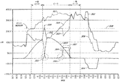
図3は、本発明の実施形態による、典型的な夏の日における、方法200の操作から生じる例示的なプロットを示す。図3の実施例において、縦軸は、kW(キロワット)による電力を示し、横軸は一日の時間を示す。ピーク、及び一部ピーク需要期間の時間が図3に示される。
FIG. 3 shows an exemplary plot resulting from operation of
図3は、設備負荷103の総需要のプロット301、設備負荷103の制御された需要のプロット302、光起電システム102の出力のプロット303、エネルギー貯蔵システム101の供給のプロット304、及び設備負荷103の正味需要のプロット309を示す。プロット304の正の値は、電気エネルギーを設備負荷103に放電するエネルギー貯蔵システム101を示し、負の値は、電力系統105により充電されるエネルギー貯蔵システム101を示す。
FIG. 3 illustrates a
制御された需要のプロット302は、設備負荷103の総需要から、光起電システム102の出力及びエネルギー貯蔵システム101の出力又は入力をマイナスしたものである。正味需要(プロット309)が、ピーク需要限界(308参照)を超えて増大するとき、制御システム110は、方法200(図2参照)の段階203におけるピーク需要限界を満たすように、エネルギー貯蔵システム101に、設備負荷103(305及び306を参照)に十分な電気エネルギーを(〜最大電力で)放電するように命令する。これは、ピーク需要限界を超えない、制御された需要のプロット302を生じる。エネルギー貯蔵システム101が、ピーク需要期間における残余の時間と等しいか又はより長い期間にわたり、最大電力で電気エネルギーを供給するのに十分なエネルギーを有する場合、制御システム110は、エネルギー貯蔵システム101に、需要期間の残余の時間にわたり(すなわち、方法200の段階205におけるピーク需要期間の最後まで)、電気エネルギーを最大電力で放電する(307参照)ように命令する。
The controlled
上記の需要限界手法は、一季節の一期間(夏のピーク期間)にわたってのみ適用されるが、需要限界手法は、異なる季節の異なる期間にわって適用されてもよい。異なる期間にわたり、利用可能な供給エネルギーを最適に分配することにより、ピーク期間のみにわたって需要限界手法を単純に使用するよりも、実質的により良好な結果が得られる場合がある。例えば、別個の需要限界をピーク期間に、別個の需要限界を一部ピーク期間に、かつ別個の需要限界をオフピーク期間に設定することにより、異なる期間に異なる需要限界が設定され得る。夏のピーク期間に対する別個の需要限界、冬のピーク期間に対する別個の需要限界など、期間はまた、季節によって更に最適化されてもよい。正味需要の予測と需要限界の割り当ての組み合わせることにより、太陽エネルギー資源及びその下の設備負荷の変化による通常を下回る性能の恐れが低減されて、より高い価値をもたらし得る。 Although the above demand limit method is applied only over one period of a season (summer peak period), the demand limit method may be applied over different periods of different seasons. Optimal distribution of available supply energy over different time periods may yield substantially better results than simply using the demand limit approach over peak periods only. For example, different demand limits can be set for different periods by setting separate demand limits to peak periods, separate demand limits to partial peak periods, and separate demand limits to off-peak periods. Periods may also be further optimized by season, such as separate demand limits for summer peak periods, separate demand limits for winter peak periods. By combining net demand forecasting and demand limit allocation, the risk of subnormal performance due to changes in solar energy resources and the equipment load underneath may be reduced, resulting in higher value.
エネルギーが供給される正味負荷が変化するに伴ってエネルギー貯蔵システムの値がどのように変化するかを理解するため(特に、一度システムが導入されるとこれらのパラメータ(kW及びkWh)が比較的一定であることを考慮して)、モデリング調査が発明者によって行われた。原則的に、まず、正味負荷が前提として既知であるシナリオにおいて、抽出され得る最大値を判定する。この基準値により、正味負荷形状の変化、及び正味負荷形状を予測する上でのエラーの両方の影響を判定することができる。これらの関係を調査する間、発明者は、いずれかの需要期間中(例えば、夏のピーク需要期間のみではなく)の需要を制御するように、エネルギー貯蔵システムからの電気エネルギーが供給されるようにする手法が、最も最適であることを判断した。これは、対費用効果が低い、一部ピーク及びオフピークの需要電力料金に対処するために、有意な追加的期間が加えなければならないことを示した、他のより単純な手法に基づく先行の発見とは対照的である。本明細書において開示される需要限界手法は、夏以外のピーク期間中に、より短期間の貯蔵が、選択的に供給されることを可能にする。需要限界手法はまた、非ピークの需要電力料金を低減させ、有意な追加的な価値をもたらす。需要限界手法は、正味負荷が需要限界を下回ったときに、貯蔵電力を再充電することを可能にするため、これは比較的短い期間の貯蔵電力を、負荷を平準化して、一日の遅い時間へと延ばし、一方でピーク負荷に供給する。これはまた、貯蔵が、冬の期間に一部ピーク及びオフピーク需要の両方をカバーするために、より長い期間(最大電力出力よりも低い)を達成するように設定されることを可能にする。 To understand how the value of the energy storage system changes as the net load supplied with energy changes (especially once these systems are introduced, these parameters (kW and kWh) are relatively A modeling study was conducted by the inventor, taking into account that it was constant. In principle, first the maximum value that can be extracted is determined in a scenario where the net load is known as a premise. With this reference value, it is possible to determine the influence of both a change in the net load shape and an error in predicting the net load shape. While investigating these relationships, the inventor appears to be supplied with electrical energy from the energy storage system to control demand during any demand period (eg, not just during summer peak demand periods). It was judged that the method of making was the most optimal. This is a prior discovery based on other simpler methods that showed that a significant additional period must be added to deal with some peak and off-peak electricity tariffs that are less cost-effective In contrast to The demand limit approach disclosed herein allows shorter term storage to be selectively provided during peak periods other than summer. The demand limit approach also reduces non-peak power demand rates and provides significant additional value. The demand limit approach allows the stored power to be recharged when the net load falls below the demand limit, so this is a relatively short period of storage power, leveling the load and slowing down the day Extend to time while supplying peak load. This also allows storage to be set to achieve a longer period (lower than maximum power output) to cover both partial peak and off-peak demand during the winter period.
具体的に、異なる期間の(特に、一部ピーク期間の)需要限界レベルを平準化することにより、有意な利益をもたらすことができる。需要限界手法は、各月の各期間における最大需要を推定し、その後各期間における最大需要を、エネルギー貯蔵装置の電力定格よりも低いレベルに設定してもよい。これらの需要限界レベルの調整は単に、所定の需要期間において、エネルギー貯蔵システムが、その電力定格の100%未満の出力に制限されることを意味する。これは、この期間中におけるエネルギー貯蔵システムの利用可能な期間を有効に延ばす。一部ピーク期間の供給レベルの低減は特に有効であり、これは、それによって常時の需要電力料金が(適用可能な場合)低減されるためである。需要限界レベルの適切な調整はまた、年毎の、正味負荷形状の変化の不の影響を低減させるためにも有効である。 In particular, leveling demand margin levels for different periods (particularly for some peak periods) can provide significant benefits. The demand limit method may estimate the maximum demand in each period of each month, and then set the maximum demand in each period to a level lower than the power rating of the energy storage device. These demand limit level adjustments simply mean that in a given demand period, the energy storage system is limited to an output of less than 100% of its power rating. This effectively extends the usable period of the energy storage system during this period. Reducing the supply level during some peak periods is particularly effective because it reduces the normal demand for electricity charges (if applicable). Appropriate adjustment of demand limit levels is also effective in reducing the uninfluenced effects of net load shape changes from year to year.
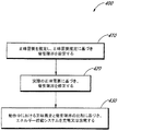
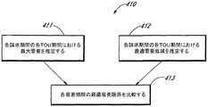
図4は、本発明の実施形態による、エネルギー貯蔵システムから電気エネルギーを供給する方法400の流れ図を示す。方法400は、エネルギー貯蔵システム101からの電気エネルギーを供給するために、制御システム110により実行され得る。図4の実施例により、方法400は、段階410、420、及び430を備える。これらの段階はそれぞれ、図5、6、及び7を参照して更に説明される。図4〜7の方法は、単に例示目的のために、図1に示される構成要素を参照して説明される。
FIG. 4 shows a flow diagram of a
図4の実施例において、方法400は、正味需要を推定し、推定正味需要に基づいて需要限界を設定する段階を含む(段階410)。この段階は、計画段階においてオフラインで、及び直近のデータ履歴に基づいてシステムの動作中に周期的に行ってもよい。設備負荷103の正味需要がモニタリングされ、需要限界が、設備負荷103の実際の正味需要に基づいてリアルタイムで(すなわち、発電システムの動作中に)修正される(段階420)。一実施形態において、設備負荷103の正味需要は、設備負荷103により必要とされる電気エネルギーの量から、光起電システム102の出力をマイナスしたものである。エネルギー貯蔵システム101は、設備負荷103の正味需要の需要限界に対する比較に基づいて充電及び放電される(段階430)。段階420及び430は、需要期間の各間隔において実行される。
In the example of FIG. 4,
図5は、本発明の実施形態により、正味需要を推定し、推定正味需要に基づいて需要限界を設定する方法の流れ図を示す。図5の方法は、方法400の段階410の特定の実施形態である(図4参照)。図5の方法は、直近のデータ履歴に基づいて、計画段階においてオフラインで、及びシステムの動作中に周期的に行ってもよい。
FIG. 5 shows a flowchart of a method for estimating net demand and setting a demand limit based on the estimated net demand according to an embodiment of the present invention. The method of FIG. 5 is a specific embodiment of
図5の実施例において、各請求期間における、各TOU期間の最大需要が推定される(段階411)。特定の例として、需要電力料金は、ピーク期間需要電力料金、一部ピーク期間需要電力供給、及び常時の需要電力料金に基づいて、1ヶ月ごとの請求期間に請求されてもよい。月の各TOU期間(例えば、ピーク、一部ピーク、オフピーク、又は常時)の最大需要電力料金は、過去の状態、並びに、天気及び/又は需要の予測に基づいて推定され得る。次の月の各TOU期間に最大需要電力料金の推定は、現在の月の最後に行われてもよい。 In the example of FIG. 5, the maximum demand for each TOU period in each billing period is estimated (step 411). As a specific example, the demand power rate may be charged in a monthly billing period based on peak period demand power rate, partial peak period demand power supply, and constant demand power rate. The maximum demand power rate for each TOU period of the month (eg, peak, partial peak, off-peak, or always) may be estimated based on past conditions and weather and / or demand forecasts. The estimation of the maximum power demand rate during each TOU period of the next month may be performed at the end of the current month.
図5の実施例において、請求期間内の各TOU期間内の最適需要低減が推定される(段階412)。最適化した需要低減は、各需要期間における最大需要低減を、エネルギー貯蔵システム101の電力定格の100%より小さいか等しい割合に設定する。最適化した需要低減は、過去のデータを使用した、経済的最適化に基づく場合がある。最適化した需要低減は、全年に関して設定されてもよく、又は前の月、若しくは関心の別の期間に基づいてもよい。
In the example of FIG. 5, the optimal demand reduction within each TOU period within the billing period is estimated (step 412). The optimized demand reduction sets the maximum demand reduction in each demand period to a rate that is less than or equal to 100% of the power rating of the
各期間における最適需要限界は、各請求期間における各TOU期間の推定最大需要、及び請求期間内の各TOU期間の推定最適需要低減に基づいて計算され得る(段階413)。例えば、最適需要限界は、推定最大需要から、最適需要低減をマイナスしたものであり得る。最適需要限界はその後、図7の方法におけるように、発電システムの動作中の、需要限界として使用され得る。最適需要限界は、図6を参照して説明されるように、発電システムの動作中に動的に調節されてもよい。 The optimal demand limit in each period may be calculated based on the estimated maximum demand for each TOU period in each billing period and the estimated optimal demand reduction for each TOU period in the billing period (stage 413). For example, the optimum demand limit may be the estimated maximum demand minus the optimum demand reduction. The optimal demand limit can then be used as the demand limit during operation of the power generation system, as in the method of FIG. The optimal demand limit may be adjusted dynamically during operation of the power generation system, as described with reference to FIG.
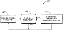
図6は、本発明の実施形態により、需要限界を修正する方法の流れ図を示す。図6の方法は、方法420の段階400の特定の実施形態である(図4参照)。図6の方法は、需要期間の各間隔において、リアルタイムで(すなわち、発電システムの通常動作中において)行われる。有利であることに、図6の方法は、需要限界の動的調節が負荷条件の変更に適合することを可能にする。
FIG. 6 shows a flow diagram of a method for correcting a demand limit according to an embodiment of the present invention. The method of FIG. 6 is a specific embodiment of
図6の例において、設備負荷103の正味需要は、間隔の最後までモニタリングされる(段階421)。設備負荷103の正味需要の平均は、先に計算された需要限界(図5の段階413参照)に対して比較される(段階422)。設備負荷103の正味需要の平均が、推定最大需要より大きいか等しいとき、制御システム110は、推定最大需要を、直前の間隔の実際の正味需要と同じレベルに再設定し(段階422〜423)、新しい推定最大需要を最適需要低減から引くことによって、需要限界を再計算する。あるいは、設備負荷103の正味需要の平均が、推定最大需要よりも低い場合、制御システム110は、間隔の最後まで、設備負荷103の正味需要を単純にモニタリングし続ける(段階422〜421)。
In the example of FIG. 6, the net demand for
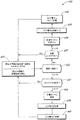
図7は、本発明の実施形態による、エネルギー貯蔵システムを充電及び放電する方法の流れ図を示す。図7の方法は、方法400の段階430の特定の実施形態である(図4参照)。図7の方法は、図6の方法と共に、需要期間の各間隔において、リアルタイムで(すなわち、発電システムの通常動作中において)行われる。
FIG. 7 shows a flowchart of a method for charging and discharging an energy storage system according to an embodiment of the present invention. The method of FIG. 7 is a specific embodiment of
図7の実施例において、制御システム110は、現在の間隔の需要限界を読み、現在の間隔の最後まで設備負荷103の正味需要をモニタリングする(段階431)。現在の間隔における需要限界が、レジスターに、表に、又は変数として、例えば、計画段階中に若しくは動作中に周期的にオフラインで計算した後(図5の段階413参照)、あるいは、図6に関して記載されたようにリアルタイムで調節した後に、貯蔵されてもよい(図6の段階423を参照)。制御システム110は、現在の時間及びデータに基づいて、現在の間隔の需要限界を選択してもよい。制御システム110はその後、設備負荷103の正味需要を需要限界と比較する(段階432)。
In the example of FIG. 7, the
設備負荷103の正味需要が、需要限界よりも大きいものと予測される場合(例えば、正味需要の現在の傾向に基づいて)、制御システム110は、放電ロックアウトが適切に設定されているか点検する(段階432〜433)。エネルギー貯蔵システム101の充電又は放電は、実装形態により、例えば、TOU期間、エネルギー貯蔵システム101の充電状態、需要期間の残余時間など、1又は複数の基準に基づいて阻止されてもよい。放電ロックアウトが適切に設定されているとき(すなわち、放電が阻止されているとき)制御システム110は、エネルギー貯蔵システム101の放電を実行しない。その代わりに、制御システム110は、設備負荷103の正味需要を単純にモニタリングし続ける(段階433〜段階431)。あるいは、放電ロックアウトが適切に設定されていないとき、制御システム110は、エネルギー貯蔵システム101を放電モードに設定する(段階433〜434)。制御システム110は、出力電力が、エネルギー貯蔵システム101によって放電されることを判断する(段階435)。一実施形態において、制御システム110は、出力電力が、 a)命令電力=設備負荷103の正味需要−需要限界 b)電力限界(最適需要低減) c)エネルギー限界(エネルギー貯蔵システム101の使用可能な充電の状態が、間隔の終わりに0%と等しくなる電力)のうち最も小さなものに基づいて、エネルギー貯蔵システム101によって放電されることを判断する。 エネルギー貯蔵システム101の使用可能な充電(SOUC)の状態は、循環範囲の所望の深さに基づく、エネルギー貯蔵システム101に残っている使用可能な電気エネルギーの割合である。制御システム110はまた、本発明の利益から逸脱することなく、出力電力が、他の要素又は方法を用いて、エネルギー貯蔵システム101により放電されることを判断し得る。
If the net demand for the
制御システム110は、エネルギー貯蔵システム101に出力電力において放電するように命令し(段階436)、設備負荷103の正味需要のモニタリングを継続する(段階436〜431)。
The
設備負荷103の正味需要が、需要限界よりも大きいものと予測されない場合、制御システム110は、充電ロックアウトが適切に設定されているか点検する(段階432〜437)。充電ロックアウトが適切に設定されるとき(すなわち、充電が阻止される)、制御システム110は、エネルギー貯蔵システム101の充電が実行されず、設備負荷103の正味需要のモニタリングを単に継続する(段階437〜431)。あるいは、充電ロックアウトが適切に設定されていないとき、制御システム110は、エネルギー貯蔵システム101を充電モードに設定する(段階437〜438)。制御システム110は、入力電力がエネルギー貯蔵システム101を充電することを判断する(段階439)。一実施形態において、制御システム110は、入力電力が、 a)命令電力=需要限界−設備負荷103の正味需要 b)電力限界(エネルギー貯蔵システムネームプレート充電電力101(kW)) c)エネルギー限界(エネルギー貯蔵システム101のSOUCが間隔の終わりで100%に等しくなる電力)のうちの最も小さいものに基づいてエネルギー貯蔵システム101を充電することを判断する。
If the net demand for the
制御システム110はまた、本発明の利益から逸脱することなく、出力電力が、他の要素又は方法を用いて、エネルギー貯蔵システム101を充電することを判断し得る。
The
制御システム110は、エネルギー貯蔵システム101に入力電力において充電するように命令する(段階440)。一実施形態において、エネルギー貯蔵システム101は、電力系統105からの電気エネルギーを使用して充電される。制御システム110は、設備負荷103の正味需要を単純にモニタリングし続ける(段階440〜段階431)。
The
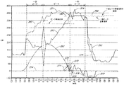
図8は、本発明の実施形態による、図4〜7の方法の操作から生じる、例示的なプロットを示す。図8の実施例において、縦軸は、kWによる電力を示し、横軸は1日の時間を示す。ピーク、及び一部ピーク需要期間の時間が図8に示される。ピーク及び一部ピーク需要期間外の時間においてオフピーク需要期間が生じる。 FIG. 8 shows an exemplary plot resulting from operation of the method of FIGS. 4-7, according to an embodiment of the invention. In the example of FIG. 8, the vertical axis indicates the power by kW, and the horizontal axis indicates the time of one day. The peak and partial peak demand periods are shown in FIG. Off-peak demand periods occur at times outside of peak and partial peak demand periods.
図8は、設備負荷103の総需要のプロット351、設備負荷103の制御された需要のプロット352、光起電システム102の出力のプロット353、エネルギー貯蔵システム101の充電及び放電のプロット354、及び設備負荷103の正味需要のプロット379を示す。制御された需要のプロット352は、設備負荷103の総需要から、光起電システム102及びエネルギー貯蔵システム101の出力をマイナスしたものである。正味需要(プロット379)が、ピーク需要期間中にピーク需要限界(365参照)を超えて増大するとき、図4の段階430において、更に、図7の段階438〜440において更に詳細に示されるように、制御システム110は、エネルギー貯蔵システム101が、ピーク需要限界(371及び372参照)を満たすように、十分な電力を放電するように命令する。これは、ピーク需要限界を超えない、制御された需要のプロット352を生じる。
FIG. 8 includes a
同様に、正味需要(プロット379)が、一部ピーク需要期間中にピーク需要限界(367参照)を超えて増大するとき、方法400の段階430において、更に、図7の段階438〜440において更に詳細に示されるように、制御システム110は、エネルギー貯蔵システム101が、一部ピーク需要限界(373参照)を満たすように、十分な電力を放電するように命令する。一部ピーク需要期間中の同じ点において、平均正味需要は、推定最大一部ピーク需要よりも大きい。これに応じ、制御システム110は、図4の段階420におけるように、かつ更に詳細には図6の段階421〜423におけるように、推定最大一部ピーク需要をより高いレベルへと動的に増大させ、これにより調節された一部ピーク需要限界を生じさせる(366参照)。
Similarly, when the net demand (plot 379) increases beyond the peak demand limit (see 367) during a partial peak demand period, further at
図8の例において、プロット354の負の値は、エネルギー貯蔵システム101が充電していることを示し、正の値はエネルギー貯蔵システム101が放電していることを示す。図4の段階430、及び更に詳細には図7の段階434〜436におけるように、エネルギー貯蔵システム101の充電は、正味需要が需要限界未満であるときに生じる(375〜377)。
In the example of FIG. 8, a negative value on
図8の実施例において、正味需要は夏のピーク需要限界を16時から超え、貯蔵システム101は、この需要レベル(プロット354の正の値)を維持するように放電する。17時は、ピーク需要期間の終了時であり、一部ピーク需要期間の開始時であり、そのため需要限界レベルは一部ピークの値へと再設定される。方法は、正味需要が需要限界を下回るときに、エネルギー貯蔵システム101が充電することを可能にし、需要限界レベルが維持され得る期間を延長し、午後の一部ピーク需要期間における正味需要を効果的に平均化することに留意されたい。18時15分に、設備需要が前の予測されたレベルを超えると、動的需要限界の再設定により一部ピーク需要限界の上方への再設定が生じる。オフピーク需要期間は20時30分から始まる。オフピーク需要限界はまた、エネルギー貯蔵システム101の再充電がオフピーク又は常時の需要電力料金に影響しないように、設定され得る。いくつかの場合において、エネルギー貯蔵システム101はまた、オフピーク又は常時の需要限界を維持するために、オフピーク需要期間中に放電してもよい。異なる期間における調整された各需要限界レベルパラメータは、光起電システム、エネルギー貯蔵システム、及び設備負荷をモデリングし、最大達成可能値を繰り返し出すことによって調節され得る。これは、変化する条件によりよく適合するように、規則的に(例えば、毎月)行われてもよい。
In the example of FIG. 8, the net demand exceeds the summer peak demand limit from 16:00 and the
上記の実施形態は、期間が制限された、エネルギー貯蔵を含む。設備により供給される天然ガスにより駆動されるマイクロタービンの場合におけるように、エネルギー貯蔵の期間が制限されない他の実施形態において、最適化を必要としない、燃料費、操作費用、及び維持費などの、他の制約が存在し得る。それでも、本明細書において記載されるように、需要の予測を確立すること、この需要を動的に再設定すること、及び各需要期間における最適供給レベルを判断することは、期間が制限されないエネルギー貯蔵に直接応用可能である。 The above embodiments include energy storage with limited duration. In other embodiments where the duration of energy storage is not limited, as in the case of a micro-turbine driven by natural gas supplied by the equipment, such as fuel costs, operating costs, and maintenance costs that do not require optimization There may be other constraints. Nevertheless, as described herein, establishing a forecast of demand, dynamically resetting this demand, and determining the optimal supply level in each demand period are energy that is not time limited. It can be applied directly to storage.
エネルギー貯蔵システムからの電気エネルギーを供給するための方法及び装置が開示されている。本発明の具体的な実施形態を提供したが、これらの実施形態は例示を目的としたものであり、限定的なものでないことは理解されよう。多くの追加的実施形態が、本開示を読む当業者にとっては明らかとなろう。
(項目1)
光起電システムにより生成される電気エネルギーを供給する方法であって、前記方法は、
光起電システムからの電気エネルギーで電池を充電する段階と、
設備負荷の電気エネルギー需要をモニタリングする段階と、
第1の需要期間の第1の需要限界を設定する段階と、
前記設備負荷の第1の電気エネルギー需要を、前記第1の需要期間の前記第1の需要限界と比較する段階と、
前記設備負荷の前記第1の電気エネルギー需要が、前記第1の需要限界よりも低いと予測されると判断することに応じて、前記電池が、前記第1の需要期間における残余の時間よりも長い期間にわたり、放電限界において電気エネルギーを供給できるかどうかを判断する段階と、
前記電池が、前記第1の需要期間の前記残余の時間より長い時間にわたり、前記放電限界において、電気エネルギーを供給できるかどうかを判断することに応じて、前記放電限界において前記電池から電気エネルギーを放電する段階と、を備える方法。
(項目2)
前記設備負荷の前記第1の電気エネルギー需要が前記第1の需要限界よりも大きいと判断することに応じて、前記第1の需要限界に基づき前記電池から電気エネルギーを放電する段階を更に備える、請求項1に記載の方法。
(項目3)
前記電池は、前記設備負荷の前記第1の電気エネルギー需要のレベルと前記第1の需要限界のレベルとの間の差と等しい電気エネルギーを放電する、請求項1又は2に記載の方法。
(項目4)
前記放電限界は、前記電池の100%の電力定格である、請求項1〜3の何れか1項に記載の方法。
(項目5)
前記放電限界は、前記電池の100%の電力定格でない、請求項1〜4の何れか1項に記載の方法。
(項目6)
第2の需要期間の第2の需要限界を設定する段階と、
前記設備負荷の第2の電気エネルギー需要を、前記第2の需要期間の前記第2の需要限界と比較する段階とを更に備え、
前記第2の需要限界は、前記第1の需要限界とは異なり、前記第2の需要期間は、前記第1の需要期間の直後である、請求項1〜5の何れか1項に記載の方法。
(項目7)
発電システムであって、
エネルギー貯蔵システムと、
前記エネルギー貯蔵システムを充電する光起電システムと、
前記エネルギー貯蔵システムから設備負荷への電気エネルギーの供給を制御する制御システムとを備え、前記制御システムは、前記設備負荷の電気エネルギー需要をモニタリングし、前記設備負荷の前記需要を需要期間の需要限界と比較し、前記エネルギー貯蔵システムが、需要期間の残余の時間よりも長い期間にわたり放電限界において放電するために十分な電気エネルギーを有するときに、前記放電限界で前記エネルギー貯蔵システムから電気エネルギーを放電する発電システム。
(項目8)
前記エネルギー貯蔵システムが電池を有する、請求項7に記載の発電システム。
(項目9)
光起電システムにより生成される電気エネルギーを供給する方法であって、前記方法は、
光起電システムからの電気エネルギーでエネルギー貯蔵システムを充電する段階と、
設備負荷の電気エネルギー需要をモニタリングする段階と、
第1の需要期間中に前記設備負荷の第1の電気エネルギー需要を第1の需要限界と比較する段階と、
前記エネルギー貯蔵システムが、前記第1の需要期間の残余の時間よりも長い期間にわたって、第1の放電限界において電気エネルギーを供給することができることを検出する段階と、
前記エネルギー貯蔵システムが、前記第1の需要期間の前記残余の時間よりも長い時間にわたり、前記第1の放電限界において、電気エネルギーを供給できると検出することに応じて、前記第1の放電限界において前記エネルギー貯蔵システムから電気エネルギーを放電する段階と
を備える方法。
(項目10)
前記設備負荷の前記第1の電気エネルギー需要が、前記第1の需要限界よりも大きいと検出することに応じて、前記第1の需要限界に基づいて前記エネルギー貯蔵システムから電気エネルギーを放電する段階を更に備える、請求項9に記載の方法。
A method and apparatus for supplying electrical energy from an energy storage system is disclosed. While specific embodiments of the present invention have been provided, it will be understood that these embodiments are for illustrative purposes and are not limiting. Many additional embodiments will be apparent to persons of ordinary skill in the art reading this disclosure.
(Item 1)
A method of supplying electrical energy generated by a photovoltaic system, the method comprising:
Charging the battery with electrical energy from the photovoltaic system;
Monitoring the electrical energy demand of the equipment load;
Setting a first demand limit for a first demand period;
Comparing the first electrical energy demand of the facility load with the first demand limit of the first demand period;
In response to determining that the first electrical energy demand of the facility load is predicted to be lower than the first demand limit, the battery is more than the remaining time in the first demand period. Determining whether electrical energy can be supplied at the discharge limit over a long period of time;
In response to determining whether the battery can supply electrical energy at the discharge limit for a time longer than the remaining time of the first demand period, And discharging.
(Item 2)
In response to determining that the first electrical energy demand of the facility load is greater than the first demand limit, further comprising discharging electrical energy from the battery based on the first demand limit; The method of
(Item 3)
The method according to
(Item 4)
The method according to
(Item 5)
The method according to
(Item 6)
Setting a second demand limit for the second demand period;
Comparing the second electrical energy demand of the facility load with the second demand limit of the second demand period;
The second demand limit is different from the first demand limit, and the second demand period is immediately after the first demand period. Method.
(Item 7)
A power generation system,
An energy storage system;
A photovoltaic system for charging the energy storage system;
A control system that controls the supply of electrical energy from the energy storage system to the equipment load, the control system monitoring the electrical energy demand of the equipment load and determining the demand of the equipment load as a demand limit during a demand period Compared to the above, when the energy storage system has sufficient electrical energy to discharge at the discharge limit for a period longer than the remaining time of the demand period, the electrical energy is discharged from the energy storage system at the discharge limit. Power generation system.
(Item 8)
The power generation system of claim 7, wherein the energy storage system comprises a battery.
(Item 9)
A method of supplying electrical energy generated by a photovoltaic system, the method comprising:
Charging the energy storage system with electrical energy from the photovoltaic system;
Monitoring the electrical energy demand of the equipment load;
Comparing a first electrical energy demand of the equipment load with a first demand limit during a first demand period;
Detecting that the energy storage system is capable of supplying electrical energy at a first discharge limit for a period longer than the remaining time of the first demand period;
In response to detecting that the energy storage system is capable of supplying electrical energy at the first discharge limit for a time longer than the remaining time of the first demand period, the first discharge limit. Discharging electrical energy from the energy storage system in
A method comprising:
(Item 10)
Discharging electrical energy from the energy storage system based on the first demand limit in response to detecting that the first electrical energy demand of the facility load is greater than the first demand limit. The method of claim 9, further comprising:
Claims (12)
光起電システムからの電気エネルギーで電池を充電する段階と、
設備負荷の電気エネルギー需要をモニタリングする段階と、
第1の需要期間の第1の需要限界を設定する段階と、
前記設備負荷の第1の電気エネルギー需要を、前記第1の需要期間の前記第1の需要限界と比較する段階と、
前記設備負荷の前記第1の電気エネルギー需要が、前記第1の需要限界よりも大きいと予測されると判断し、前記第1の需要限界に基づいて前記電池が放電すべき電気エネルギーを前記設備負荷の前記第1の電気エネルギー需要から減算した制御需要が前記第1の需要限界を超えないように前記電気エネルギーを放電することに応じて、前記電池が、前記第1の需要期間における残余の時間よりも長い期間にわたり、放電限界において電気エネルギーを供給できるかどうかを判断する段階と、
前記電池が、前記第1の需要期間の前記残余の時間より長い時間にわたり、前記放電限界において、電気エネルギーを供給できるかどうかを判断することに応じて、前記放電限界において前記電池から電気エネルギーを放電する段階と、を備える方法。 A method of supplying electrical energy generated by a photovoltaic system, the method comprising:
Charging the battery with electrical energy from the photovoltaic system;
Monitoring the electrical energy demand of the equipment load;
Setting a first demand limit for a first demand period;
Comparing the first electrical energy demand of the facility load with the first demand limit of the first demand period;
It is determined that the first electrical energy demand of the equipment load is predicted to be greater than the first demand limit, and the electrical energy to be discharged by the battery based on the first demand limit is the equipment. Responsive to discharging the electrical energy such that a control demand subtracted from the first electrical energy demand of a load does not exceed the first demand limit, the battery has a residual in the first demand period. Determining whether electrical energy can be delivered at the discharge limit over a longer period of time; and
In response to determining whether the battery can supply electrical energy at the discharge limit for a time longer than the remaining time of the first demand period, And discharging.
前記設備負荷の第2の電気エネルギー需要を、前記第2の需要期間の前記第2の需要限界と比較する段階とを更に備え、
前記第2の需要限界は、前記第1の需要限界とは異なり、前記第2の需要期間は、前記第1の需要期間の直後である、請求項1〜5の何れか1項に記載の方法。 Setting a second demand limit for the second demand period;
Comparing the second electrical energy demand of the facility load with the second demand limit of the second demand period;
The second demand limit is different from the first demand limit, and the second demand period is immediately after the first demand period. Method.
エネルギー貯蔵システムと、
前記エネルギー貯蔵システムを充電する光起電システムと、
前記エネルギー貯蔵システムから設備負荷への電気エネルギーの供給を制御する制御システムと、
を備え、
前記制御システムは、
前記設備負荷の電気エネルギー需要をモニタリングし、
前記設備負荷の前記電気エネルギー需要を需要期間の需要限界と比較し、
前記設備負荷の前記電気エネルギー需要が前記需要限界よりも大きい場合に、前記需要限界に基づいて前記エネルギー貯蔵システムが放電すべき電気エネルギーを前記設備負荷の前記電気エネルギー需要から減算した制御需要が前記需要限界を超えないように前記電気エネルギーを放電し、前記エネルギー貯蔵システムが、前記需要期間の残余の時間よりも長い期間にわたり放電限界において放電するために十分な電気エネルギーを有するときに、前記放電限界で前記エネルギー貯蔵システムから電気エネルギーを放電する発電システム。 A power generation system,
An energy storage system;
A photovoltaic system for charging the energy storage system;
A control system for controlling the supply of electrical energy from the energy storage system to the equipment load;
With
The control system is
Monitoring the electrical energy demand of the equipment load;
Comparing the electrical energy demand of the equipment load with the demand limit of a demand period;
When the electrical energy demand of the facility load is greater than the demand limit, the control demand the energy storage system based on the demand limit by subtracting the electric energy to be discharged from the electric energy demand of the facility load Discharging the electrical energy so as not to exceed the demand limit , and when the energy storage system has sufficient electrical energy to discharge at the discharge limit for a period longer than the remainder of the demand period; A power generation system that discharges electrical energy from the energy storage system at a discharge limit.
光起電システムからの電気エネルギーでエネルギー貯蔵システムを充電する段階と、
設備負荷の電気エネルギー需要をモニタリングする段階と、
第1の需要期間中に前記設備負荷の第1の電気エネルギー需要を第1の需要限界と比較する段階と、
前記設備負荷の前記第1の電気エネルギー需要が前記第1の需要限界よりも大きい場合に、前記第1の需要限界に基づいて前記エネルギー貯蔵システムが放電すべき電気エネルギーを前記設備負荷の前記第1の電気エネルギー需要から減算した制御需要が前記第1の需要限界を超えないように前記電気エネルギーを放電し、前記エネルギー貯蔵システムが、前記第1の需要期間の残余の時間よりも長い期間にわたって、第1の放電限界において電気エネルギーを供給することができることを検出する段階と、
前記エネルギー貯蔵システムが、前記第1の需要期間の前記残余の時間よりも長い時間にわたり、前記第1の放電限界において、電気エネルギーを供給できると検出することに応じて、前記第1の放電限界において前記エネルギー貯蔵システムから電気エネルギーを放電する段階と
を備える方法。 A method of supplying electrical energy generated by a photovoltaic system, the method comprising:
Charging the energy storage system with electrical energy from the photovoltaic system;
Monitoring the electrical energy demand of the equipment load;
Comparing a first electrical energy demand of the equipment load with a first demand limit during a first demand period;
When the first electrical energy demand of the facility load is greater than the first demand limit, the electric energy to be discharged is the energy storage system based on the first demand limits of the equipment load The electrical energy is discharged so that the control demand subtracted from the first electrical energy demand does not exceed the first demand limit, and the energy storage system is longer than the remaining time of the first demand period And detecting that electrical energy can be supplied at the first discharge limit;
In response to detecting that the energy storage system is capable of supplying electrical energy at the first discharge limit for a time longer than the remaining time of the first demand period, the first discharge limit. Discharging electrical energy from the energy storage system.
Applications Claiming Priority (5)
| Application Number | Priority Date | Filing Date | Title |
|---|---|---|---|
| US201261589158P | 2012-01-20 | 2012-01-20 | |
| US61/589,158 | 2012-01-20 | ||
| US13/420,376 US10069300B2 (en) | 2012-01-20 | 2012-03-14 | Methods and apparatus for dispatching electrical energy from distributed energy resources |
| US13/420,376 | 2012-03-14 | ||
| PCT/US2012/068981 WO2013109356A1 (en) | 2012-01-20 | 2012-12-11 | Methods and apparatus for dispatching electrical energy from distributed energy resources |
Publications (2)
| Publication Number | Publication Date |
|---|---|
| JP2015510747A JP2015510747A (en) | 2015-04-09 |
| JP6168564B2 true JP6168564B2 (en) | 2017-07-26 |
Family
ID=48797880
Family Applications (1)
| Application Number | Title | Priority Date | Filing Date |
|---|---|---|---|
| JP2014553296A Active JP6168564B2 (en) | 2012-01-20 | 2012-12-11 | Method and power generation system for supplying electrical energy from a distributed energy source |
Country Status (8)
| Country | Link |
|---|---|
| US (1) | US10069300B2 (en) |
| EP (1) | EP2805212B1 (en) |
| JP (1) | JP6168564B2 (en) |
| CN (1) | CN104220945B (en) |
| AU (1) | AU2012366196B2 (en) |
| CL (1) | CL2014001910A1 (en) |
| MX (2) | MX344813B (en) |
| WO (1) | WO2013109356A1 (en) |
Families Citing this family (34)
| Publication number | Priority date | Publication date | Assignee | Title |
|---|---|---|---|---|
| US8751054B2 (en) * | 2011-09-02 | 2014-06-10 | Sharp Laboratories Of America, Inc. | Energy prediction system |
| US8909358B2 (en) * | 2012-06-01 | 2014-12-09 | Sap Ag | Method and system for complex smart grid infrastructure assessment |
| KR20140023125A (en) | 2012-08-17 | 2014-02-26 | 엘지전자 주식회사 | Energy storage device, device for managing power, mobile termianl and method for operating the same |
| US9002531B2 (en) * | 2012-09-28 | 2015-04-07 | Sharp Laboratories Of America, Inc. | System and method for predictive peak load management via integrated load management |
| WO2015031331A1 (en) * | 2013-08-26 | 2015-03-05 | Robert Bosch Gmbh | Dispatch controller for an energy system |
| US9843189B2 (en) * | 2014-05-19 | 2017-12-12 | The University Of North Carolina At Charlotte | Grid tied system controller including logic coupled to a photovoltaic station and an energy storage system |
| US9948101B2 (en) * | 2014-07-03 | 2018-04-17 | Green Charge Networks Llc | Passive peak reduction systems and methods |
| US10283964B2 (en) * | 2015-07-01 | 2019-05-07 | General Electric Company | Predictive control for energy storage on a renewable energy system |
| US10466282B2 (en) | 2015-07-27 | 2019-11-05 | Sunpower Corporation | Solar energy metering, communications, and control system |
| US9985582B2 (en) | 2015-07-27 | 2018-05-29 | Sunpower Corporation | Thermal management of systems with electric components |
| US11172273B2 (en) | 2015-08-10 | 2021-11-09 | Delta Energy & Communications, Inc. | Transformer monitor, communications and data collection device |
| US10055869B2 (en) | 2015-08-11 | 2018-08-21 | Delta Energy & Communications, Inc. | Enhanced reality system for visualizing, evaluating, diagnosing, optimizing and servicing smart grids and incorporated components |
| WO2017041093A1 (en) | 2015-09-03 | 2017-03-09 | Delta Energy & Communications, Inc. | System and method for determination and remediation of energy diversion in a smart grid network |
| CA3000206C (en) | 2015-10-02 | 2023-10-17 | Delta Energy & Communications, Inc. | Supplemental and alternative digital data delivery and receipt mesh network realized through the placement of enhanced transformer mounted monitoring devices |
| US9961572B2 (en) | 2015-10-22 | 2018-05-01 | Delta Energy & Communications, Inc. | Augmentation, expansion and self-healing of a geographically distributed mesh network using unmanned aerial vehicle (UAV) technology |
| US10476597B2 (en) | 2015-10-22 | 2019-11-12 | Delta Energy & Communications, Inc. | Data transfer facilitation across a distributed mesh network using light and optical based technology |
| US10892620B2 (en) * | 2015-11-16 | 2021-01-12 | General Electric Company | State of charge maintenance during operation of energy storage systems |
| WO2017147476A1 (en) | 2016-02-24 | 2017-08-31 | Delta Energy & Communications, Inc. | Distributed 802.11s mesh network using transformer module hardware for the capture and transmission of data |
| WO2018035143A1 (en) | 2016-08-15 | 2018-02-22 | Delta Energy & Communications, Inc. | Integrated solution of internet of things and smart grid network |
| US10523010B2 (en) | 2016-11-08 | 2019-12-31 | Sunpower Corporation | Energy flow prediction for electric systems including photovoltaic solar systems |
| US10333306B2 (en) * | 2016-12-14 | 2019-06-25 | Nec Corporation | Data-driven demand charge management solution |
| US11238547B2 (en) | 2017-01-12 | 2022-02-01 | Johnson Controls Tyco IP Holdings LLP | Building energy cost optimization system with asset sizing |
| CN106894941A (en) * | 2017-01-17 | 2017-06-27 | 集美大学 | A kind of wave energy direct-drive type both vapor compression unit |
| JP6725433B2 (en) * | 2017-01-18 | 2020-07-15 | 株式会社東芝 | Controller and program |
| US10999652B2 (en) | 2017-05-24 | 2021-05-04 | Engie Storage Services Na Llc | Energy-based curtailment systems and methods |
| US10658841B2 (en) | 2017-07-14 | 2020-05-19 | Engie Storage Services Na Llc | Clustered power generator architecture |
| EP3457513A1 (en) * | 2017-09-13 | 2019-03-20 | Johnson Controls Technology Company | Building energy system with load balancing |
| GB2577853B (en) | 2018-06-22 | 2021-03-24 | Moixa Energy Holdings Ltd | Systems for machine learning, optimising and managing local multi-asset flexibility of distributed energy storage resources |
| US11121552B2 (en) * | 2018-07-02 | 2021-09-14 | Enel X North America, Inc. | Demand setpoint management in electrical system control and related systems, apparatuses, and methods |
| CN109164834B (en) * | 2018-09-13 | 2021-06-11 | 安徽尚特杰电力技术有限公司 | Self-correcting method and system for errors of photovoltaic tracking system |
| CN112766627B (en) * | 2019-11-06 | 2023-11-28 | 珠海优特电力科技股份有限公司 | Control method and device for controllable electric facility, storage medium and electronic device |
| US11399065B1 (en) * | 2020-01-06 | 2022-07-26 | Vybe Energy, Llc | Apparatus, system, method, and computer program product for scaling and managing electric power systems |
| US12386325B2 (en) | 2022-04-28 | 2025-08-12 | Inventus Holdings, Llc | Staggered cooling system controls for battery energy storage systems |
| US20240354775A1 (en) * | 2023-04-24 | 2024-10-24 | Voltus, Inc. | Emission based energy usage management for electrical power systems |
Family Cites Families (27)
| Publication number | Priority date | Publication date | Assignee | Title |
|---|---|---|---|---|
| US4971136A (en) * | 1989-11-28 | 1990-11-20 | Electric Power Research Institute | Dual fuel heat pump controller |
| US6889122B2 (en) | 1998-05-21 | 2005-05-03 | The Research Foundation Of State University Of New York | Load controller and method to enhance effective capacity of a photovoltaic power supply using a dynamically determined expected peak loading |
| US6037758A (en) | 1998-05-21 | 2000-03-14 | The Research Foundation Of State University Of New York | Load controller and method to enhance effective capacity of a photovoltaic power supply |
| US6542791B1 (en) | 1998-05-21 | 2003-04-01 | The Research Foundation Of State University Of New York | Load controller and method to enhance effective capacity of a photovotaic power supply using a dynamically determined expected peak loading |
| JP2000069673A (en) * | 1998-08-25 | 2000-03-03 | Hitachi Ltd | Power storage device control method and control device |
| US6510369B1 (en) * | 1999-08-24 | 2003-01-21 | Plug Power Inc. | Residential load shedding |
| US20020128747A1 (en) * | 2000-12-12 | 2002-09-12 | Ngk Insulators, Ltd. | Method for running electric energy storage system |
| JP2003125537A (en) * | 2001-10-11 | 2003-04-25 | Hokuriku Electric Power Co Inc:The | Discharging method for secondary battery for power storage |
| US20030171851A1 (en) * | 2002-03-08 | 2003-09-11 | Peter J. Brickfield | Automatic energy management and energy consumption reduction, especially in commercial and multi-building systems |
| WO2003084022A1 (en) | 2002-03-28 | 2003-10-09 | Robertshaw Controls Company | Energy management system and method |
| JP4607533B2 (en) * | 2004-10-06 | 2011-01-05 | 日本碍子株式会社 | Operation method of power storage system |
| US7274975B2 (en) * | 2005-06-06 | 2007-09-25 | Gridpoint, Inc. | Optimized energy management system |
| WO2008039759A2 (en) * | 2006-09-25 | 2008-04-03 | Intelligent Management Systems Corporation | System and method for resource management |
| US8600571B2 (en) | 2008-06-19 | 2013-12-03 | Honeywell International Inc. | Energy optimization system |
| US8627689B2 (en) | 2008-09-15 | 2014-01-14 | General Electric Company | Energy management of clothes washer appliance |
| US8548638B2 (en) * | 2008-09-15 | 2013-10-01 | General Electric Company | Energy management system and method |
| JP5255462B2 (en) * | 2009-01-13 | 2013-08-07 | 株式会社日立製作所 | Power supply and demand operation management server and power supply and demand operation management system |
| US8108081B2 (en) | 2009-08-12 | 2012-01-31 | Sunpower Corporation | System and method for associating a load demand with a variable power generation |
| KR101146670B1 (en) * | 2009-12-16 | 2012-05-23 | 삼성에스디아이 주식회사 | Energy management system and method for controlling thereof |
| DE102009055224B4 (en) * | 2009-12-23 | 2022-07-28 | Robert Bosch Gmbh | Hydraulic vehicle brake system |
| CN101799681A (en) * | 2010-02-10 | 2010-08-11 | 刘文祥 | Intelligent grid |
| WO2011109759A1 (en) * | 2010-03-05 | 2011-09-09 | Efficient Energy America Incorporated | System and method for providing reduced consumption of energy using automated human thermal comfort controls |
| CN102296661B (en) * | 2010-06-23 | 2015-07-22 | 广西柳工机械股份有限公司 | Energy management and assembly coordination control method for parallel-series hybrid power digger |
| JP5485857B2 (en) * | 2010-10-26 | 2014-05-07 | パナソニック株式会社 | Power management system |
| JP5807201B2 (en) * | 2010-12-28 | 2015-11-10 | パナソニックIpマネジメント株式会社 | Power control device |
| US9893526B2 (en) * | 2011-03-25 | 2018-02-13 | Green Charge Networks Llc | Networked power management and demand response |
| US20130030590A1 (en) * | 2011-07-29 | 2013-01-31 | Green Charge Networks Llc | Peak Mitigation Extension Using Energy Storage and Load Shedding |
-
2012
- 2012-03-14 US US13/420,376 patent/US10069300B2/en active Active
- 2012-12-11 AU AU2012366196A patent/AU2012366196B2/en active Active
- 2012-12-11 MX MX2014008746A patent/MX344813B/en active IP Right Grant
- 2012-12-11 WO PCT/US2012/068981 patent/WO2013109356A1/en not_active Ceased
- 2012-12-11 CN CN201280067619.3A patent/CN104220945B/en active Active
- 2012-12-11 MX MX2017000376A patent/MX371070B/en unknown
- 2012-12-11 JP JP2014553296A patent/JP6168564B2/en active Active
- 2012-12-11 EP EP12865772.3A patent/EP2805212B1/en active Active
-
2014
- 2014-07-18 CL CL2014001910A patent/CL2014001910A1/en unknown
Also Published As
| Publication number | Publication date |
|---|---|
| MX371070B (en) | 2020-01-15 |
| EP2805212A4 (en) | 2015-07-22 |
| WO2013109356A1 (en) | 2013-07-25 |
| MX344813B (en) | 2017-01-09 |
| EP2805212A1 (en) | 2014-11-26 |
| CN104220945A (en) | 2014-12-17 |
| MX2014008746A (en) | 2015-03-03 |
| EP2805212B1 (en) | 2020-07-08 |
| AU2012366196B2 (en) | 2016-10-06 |
| CL2014001910A1 (en) | 2015-01-16 |
| US10069300B2 (en) | 2018-09-04 |
| CN104220945B (en) | 2017-09-08 |
| AU2012366196A1 (en) | 2014-07-31 |
| JP2015510747A (en) | 2015-04-09 |
| US20130190939A1 (en) | 2013-07-25 |
Similar Documents
| Publication | Publication Date | Title |
|---|---|---|
| JP6168564B2 (en) | Method and power generation system for supplying electrical energy from a distributed energy source | |
| US12132418B2 (en) | Converter with power management system for household users to manage power between different loads including their electric vehicle | |
| CN110112783B (en) | Photovoltaic storage battery microgrid dispatching control method | |
| US8886363B2 (en) | Energy storage and power management system | |
| US8227937B2 (en) | Uninterruptible power supplies, solar power kits for uninterruptible power supplies and related methods | |
| JP5584763B2 (en) | DC power distribution system | |
| CN105978001B (en) | Energy storage device control method and electric power management system | |
| KR20220060547A (en) | Spare generators and associated power systems | |
| JP6592360B2 (en) | Power management method | |
| JP2023138478A (en) | Method for controlling battery energy storage systems in power systems with high dynamic loads | |
| Bagheri‐Sanjareh et al. | Energy management of islanded microgrid by coordinated application of thermal and electrical energy storage systems | |
| JP6821904B2 (en) | Power system | |
| JP7252116B2 (en) | Renewable energy power generation system | |
| JP6828567B2 (en) | Grid interconnection system and power system | |
| CN107210606A (en) | The method of energy management | |
| JP6228702B2 (en) | Power management apparatus, power management method and program | |
| JP6892191B2 (en) | Power system | |
| Teo et al. | Modelling and optimisation of stand alone power generation at rural area | |
| Sharma et al. | Novel optimal energy management with demand response for a real-time community microgrid | |
| JP2012060829A (en) | Power supply system and power supply method | |
| JP2023523471A (en) | Energy management system and method | |
| JP2025065630A (en) | Power Supply System | |
| JP2023151564A (en) | Storage battery management device and storage battery management method | |
| Asghari et al. | An Amp-hour based electricity cost model for economic dispatch of batteries in microgrids |
Legal Events
| Date | Code | Title | Description |
|---|---|---|---|
| A621 | Written request for application examination |
Free format text: JAPANESE INTERMEDIATE CODE: A621 Effective date: 20151204 |
|
| A977 | Report on retrieval |
Free format text: JAPANESE INTERMEDIATE CODE: A971007 Effective date: 20161026 |
|
| A131 | Notification of reasons for refusal |
Free format text: JAPANESE INTERMEDIATE CODE: A131 Effective date: 20161101 |
|
| A521 | Request for written amendment filed |
Free format text: JAPANESE INTERMEDIATE CODE: A523 Effective date: 20170127 |
|
| A131 | Notification of reasons for refusal |
Free format text: JAPANESE INTERMEDIATE CODE: A131 Effective date: 20170314 |
|
| A521 | Request for written amendment filed |
Free format text: JAPANESE INTERMEDIATE CODE: A523 Effective date: 20170417 |
|
| TRDD | Decision of grant or rejection written | ||
| A01 | Written decision to grant a patent or to grant a registration (utility model) |
Free format text: JAPANESE INTERMEDIATE CODE: A01 Effective date: 20170530 |
|
| A61 | First payment of annual fees (during grant procedure) |
Free format text: JAPANESE INTERMEDIATE CODE: A61 Effective date: 20170621 |
|
| R150 | Certificate of patent or registration of utility model |
Ref document number: 6168564 Country of ref document: JP Free format text: JAPANESE INTERMEDIATE CODE: R150 |
|
| R250 | Receipt of annual fees |
Free format text: JAPANESE INTERMEDIATE CODE: R250 |
|
| R250 | Receipt of annual fees |
Free format text: JAPANESE INTERMEDIATE CODE: R250 |
|
| R250 | Receipt of annual fees |
Free format text: JAPANESE INTERMEDIATE CODE: R250 |
|
| R250 | Receipt of annual fees |
Free format text: JAPANESE INTERMEDIATE CODE: R250 |
|
| R250 | Receipt of annual fees |
Free format text: JAPANESE INTERMEDIATE CODE: R250 |
|
| R250 | Receipt of annual fees |
Free format text: JAPANESE INTERMEDIATE CODE: R250 |