JP6166509B2 - Imaging apparatus and imaging method - Google Patents
Imaging apparatus and imaging method Download PDFInfo
- Publication number
- JP6166509B2 JP6166509B2 JP2012006009A JP2012006009A JP6166509B2 JP 6166509 B2 JP6166509 B2 JP 6166509B2 JP 2012006009 A JP2012006009 A JP 2012006009A JP 2012006009 A JP2012006009 A JP 2012006009A JP 6166509 B2 JP6166509 B2 JP 6166509B2
- Authority
- JP
- Japan
- Prior art keywords
- optical path
- path length
- length difference
- light
- tomographic image
- Prior art date
- Legal status (The legal status is an assumption and is not a legal conclusion. Google has not performed a legal analysis and makes no representation as to the accuracy of the status listed.)
- Expired - Fee Related
Links
- 238000003384 imaging method Methods 0.000 title claims description 51
- 230000003287 optical effect Effects 0.000 claims description 147
- 238000005259 measurement Methods 0.000 claims description 36
- 238000007689 inspection Methods 0.000 claims description 34
- 238000000034 method Methods 0.000 claims description 12
- 230000007423 decrease Effects 0.000 claims description 3
- 210000001525 retina Anatomy 0.000 description 52
- 238000012014 optical coherence tomography Methods 0.000 description 24
- 210000004126 nerve fiber Anatomy 0.000 description 4
- 210000000981 epithelium Anatomy 0.000 description 3
- 239000000049 pigment Substances 0.000 description 3
- 238000012545 processing Methods 0.000 description 3
- 238000004364 calculation method Methods 0.000 description 2
- 238000010586 diagram Methods 0.000 description 2
- 230000001678 irradiating effect Effects 0.000 description 2
- 238000012360 testing method Methods 0.000 description 2
- 208000002177 Cataract Diseases 0.000 description 1
- 238000013459 approach Methods 0.000 description 1
- 230000001427 coherent effect Effects 0.000 description 1
- 238000003745 diagnosis Methods 0.000 description 1
- 239000000835 fiber Substances 0.000 description 1
- 210000000056 organ Anatomy 0.000 description 1
- 230000004256 retinal image Effects 0.000 description 1
- 230000035945 sensitivity Effects 0.000 description 1
- 238000004904 shortening Methods 0.000 description 1
- 230000003595 spectral effect Effects 0.000 description 1
- 230000002269 spontaneous effect Effects 0.000 description 1
- 238000003325 tomography Methods 0.000 description 1
- 230000001131 transforming effect Effects 0.000 description 1
Images


Classifications
-
- G—PHYSICS
- G01—MEASURING; TESTING
- G01B—MEASURING LENGTH, THICKNESS OR SIMILAR LINEAR DIMENSIONS; MEASURING ANGLES; MEASURING AREAS; MEASURING IRREGULARITIES OF SURFACES OR CONTOURS
- G01B9/00—Measuring instruments characterised by the use of optical techniques
- G01B9/02—Interferometers
- G01B9/0209—Low-coherence interferometers
- G01B9/02091—Tomographic interferometers, e.g. based on optical coherence
-
- A—HUMAN NECESSITIES
- A61—MEDICAL OR VETERINARY SCIENCE; HYGIENE
- A61B—DIAGNOSIS; SURGERY; IDENTIFICATION
- A61B3/00—Apparatus for testing the eyes; Instruments for examining the eyes
- A61B3/10—Objective types, i.e. instruments for examining the eyes independent of the patients' perceptions or reactions
- A61B3/102—Objective types, i.e. instruments for examining the eyes independent of the patients' perceptions or reactions for optical coherence tomography [OCT]
Landscapes
- Health & Medical Sciences (AREA)
- Life Sciences & Earth Sciences (AREA)
- General Health & Medical Sciences (AREA)
- Nuclear Medicine, Radiotherapy & Molecular Imaging (AREA)
- Radiology & Medical Imaging (AREA)
- Physics & Mathematics (AREA)
- Biomedical Technology (AREA)
- Molecular Biology (AREA)
- Ophthalmology & Optometry (AREA)
- Engineering & Computer Science (AREA)
- General Physics & Mathematics (AREA)
- Heart & Thoracic Surgery (AREA)
- Medical Informatics (AREA)
- Biophysics (AREA)
- Surgery (AREA)
- Animal Behavior & Ethology (AREA)
- Public Health (AREA)
- Veterinary Medicine (AREA)
- Eye Examination Apparatus (AREA)
- Investigating Or Analysing Materials By Optical Means (AREA)
Description
本発明は、光干渉を用いて断層画像を撮像する撮像装置に関し、特に眼科診療等に用いられる干渉光学系を有する撮像装置及び撮像方法に関するものである。 The present invention relates to an imaging apparatus that captures a tomographic image using optical interference, and more particularly to an imaging apparatus and an imaging method having an interference optical system used for ophthalmic medical treatment and the like.
現在、光学機器を用いた眼科用機器として、様々なものが使用されている。
例えば、眼を観察する光学機器として、前眼部撮影機、眼底カメラ、共焦点レーザー走査検眼鏡(Scanning Laser Ophthalmoscope: SLO)、等様々な機器が使用されている。中でも、光干渉断層撮像装置(Optical Coherence Tomography:OCT、以下OCT装置と記す)は、試料の断層画像を高解像度に得る装置であり、眼科用機器として網膜の専門外来では必要不可欠な装置になりつつある。
Currently, various types of ophthalmic equipment using optical equipment are used.
For example, various devices such as an anterior ocular segment photographing machine, a fundus camera, and a confocal laser scanning ophthalmoscope (SLO) are used as optical devices for observing the eyes. Among them, an optical coherence tomography (OCT) device is a device that obtains a tomographic image of a sample with high resolution, and is an indispensable device for specialized retina outpatients as an ophthalmic device. It's getting on.
上記OCT装置は、低コヒーレント光を、サンプルに照射し、そのサンプルからの反射光を干渉系を用いて分光することで、高感度に分析、測定をする装置である。また、OCT装置は、該低コヒーレント光を該サンプル上にスキャンすることで、断層画像を高解像度に得ることができる。そのため、被検眼の眼底における網膜の断層画像を高解像度に撮像することも可能であることから、網膜の眼科診断等において広く利用されている。 The OCT apparatus is an apparatus that performs analysis and measurement with high sensitivity by irradiating a sample with low-coherent light and spectroscopically analyzing reflected light from the sample using an interference system. Further, the OCT apparatus can obtain a tomographic image with high resolution by scanning the low-coherent light on the sample. Therefore, a tomographic image of the retina on the fundus of the eye to be examined can be captured with high resolution, and is therefore widely used in ophthalmic diagnosis of the retina.
なお、該OCT装置では、走査手段を介して測定光と呼ばれる低コヒーレント光を被検眼に照射することで得られる該被検眼からの戻り光と、測定光に対応する参照光とを合波し、得られた合波光に基づいて先の断層画像を取得している。ここで、測定光の光路における参照光の光路長に対応する位置をコヒーレンスゲートと呼ぶ。コヒーレンスゲートを近い程、高解像度の断層画像が得られることが知られている。 In the OCT apparatus, the return light obtained by irradiating the eye to be examined with low-coherent light called measurement light via the scanning unit and the reference light corresponding to the measurement light are combined. The previous tomographic image is acquired based on the obtained combined light. Here, the position corresponding to the optical path length of the reference light in the optical path of the measurement light is called a coherence gate. It is known that a closer to the coherence gate, a higher resolution tomographic image can be obtained.
特許文献1では、解像度において好適な網膜の断層画像を得ることを目的として、コヒーレンスゲートを調整するために合波光を分析する1次元センサの信号対ノイズ比を閾値以上になるように調整する方法が示されている。 In Patent Document 1, for the purpose of obtaining a tomographic image of the retina suitable for resolution, a method for adjusting a signal-to-noise ratio of a one-dimensional sensor that analyzes combined light to adjust a coherence gate to be equal to or greater than a threshold value. It is shown.
しかしながら、該文献に開示される方法では、信号対ノイズ比を用いていることから、網膜に対するコヒーレンスゲートの実際の位置を判断することが難しい。このため、高解像度の断層画像を得ようとした場合には診断したい位置での解像度が低下してしまう恐れがあった。また、被検眼が、例えば白内障により、信号対ノイズ比が十分に取れない場合には、上述した制御の実行自体が困難となる場合も考えられた。 However, since the method disclosed in this document uses a signal-to-noise ratio, it is difficult to determine the actual position of the coherence gate with respect to the retina. For this reason, when trying to obtain a high-resolution tomographic image, the resolution at the position to be diagnosed may be reduced. In addition, when the eye to be examined cannot obtain a sufficient signal-to-noise ratio due to, for example, cataract, it may be difficult to execute the control described above.
また、従来のOCT装置では、モニタによって断層画像を見ながら該画像の撮像を行うが、その際に表示されている断層画像しか見ることができず、コヒーレンスゲートを網膜に近づけるという操作自体が困難であった。 Further, in the conventional OCT apparatus, the image is captured while viewing the tomographic image on the monitor, but only the tomographic image displayed at that time can be seen, and the operation itself of bringing the coherence gate closer to the retina is difficult. Met.
本発明は以上の状況に鑑みて為されたものであり、撮像対象域に対してコヒーレンスゲートをできる限り近くに設定することを可能とし、診断したい位置での高解像度の断層画像を得ることを可能とする撮像装置及び方法の提供を目的とする。 The present invention has been made in view of the above situation, and it is possible to set a coherence gate as close as possible to an imaging target area, and to obtain a high-resolution tomographic image at a position to be diagnosed. An object of the present invention is to provide an imaging apparatus and method that can be used.
上記課題を解決するために、本発明の一態様に係る撮像装置は、
測定光を照射した被検査物からの戻り光と、該測定光に対応する参照光とを合波した合波光を用いて、該被検査物の断層画像を撮る撮像装置であって、
前記測定光の光路長と前記参照光の光路長との差である光路長差を変更する変更手段と、
第1の光路長差と前記第1の光路長差の絶対値よりも光路長差の絶対値が小さい第2の光路長差とでそれぞれ取得した第1及び第2の合波光を用いて、前記被検査物の第1及び第2の断層画像を取得する断層画像取得手段と、
前記第1及び第2の断層画像の類似性を示す値が所定値よりも大きい場合には前記光路長差の絶対値が前記第2の光路長差の絶対値より小さくなる方向を、前記類似性を示す値が所定値以下の場合には前記光路長差の絶対値が前記第2の光路長差の絶対値より大きくなる方向を、前記光路長差を変更する方向として取得する方向取得手段と、
前記第2の光路長差から前記取得された方向に前記光路長差を変更させるように前記変更手段を制御する制御手段と、を有することを特徴とする。
In order to solve the above problems, an imaging device according to one embodiment of the present invention includes:
And return light from the object to be inspected that is irradiated with measuring light, and have use of the combined was multiplexed light and the reference light corresponding to the surveying constant light, an imaging device taking a tomographic image obtaining step thereof,
Changing means for changing an optical path length difference which is a difference between an optical path length of the measurement light and an optical path length of the reference light;
And we have use the first and second combined light obtained respectively by the first optical path length difference between the first absolute value second optical path length difference absolute value is smaller optical path length difference than the optical path length difference, Tomographic image acquisition means for acquiring first and second tomographic images of the inspection object;
When the value indicating the similarity between the first and second tomographic images is larger than a predetermined value , the absolute value of the optical path length difference becomes smaller than the absolute value of the second optical path length difference. absolute value and the second a larger direction than the absolute value of the optical path length difference, the direction obtaining means for obtaining a direction of changing the optical path length difference of the optical path length difference when the value indicating the sex is less than a predetermined value When,
Control means for controlling the changing means so as to change the optical path length difference in the acquired direction from the second optical path length difference.
また、上記課題を解決するために、本発明の一態様に係る撮像方法は、
測定光を照射した被検査物からの戻り光と、該測定光に対応する参照光とを合波した合波光を用いて、該被検査物の断層画像を撮る撮像方法であって、
前記測定光の光路長と前記参照光の光路長との差である光路長差の第1の光路長差と前記第1の光路長差の絶対値よりも光路長差の絶対値が小さい第2の光路長差とでそれぞれ取得した第1及び第2の合波光を用いて、前記被検査物の第1及び第2の断層画像を取得する工程と、
前記第1及び第2の断層画像の類似性を示す値が所定値よりも大きい場合には前記光路長差の絶対値が前記第2の光路長差の絶対値より小さくなる方向を、前記類似性を示す値が所定値以下の場合には前記光路長差の絶対値が前記第2の光路長差の絶対値より大きくなる方向を、前記光路長差を変更する方向として取得する工程と、
前記第2の光路長差から前記取得された方向に前記光路長差を変更させる工程と、を含むことを特徴とする。
In order to solve the above problem, an imaging method according to one embodiment of the present invention includes:
And return light from the object to be inspected that is irradiated with measuring light, and have use of the combined was multiplexed light and the reference light corresponding to the surveying constant light, an imaging method of taking a tomographic image obtaining step thereof,
The absolute value of the optical path length difference is smaller than the absolute value of the first optical path length difference of the optical path length difference that is the difference between the optical path length of the measurement light and the optical path length of the reference light. and have use the first and second combined light obtained respectively by the optical path length difference of 2, to obtain the first and second tomographic image of the inspection object process,
When the value indicating the similarity between the first and second tomographic images is larger than a predetermined value , the absolute value of the optical path length difference becomes smaller than the absolute value of the second optical path length difference. a step of acquiring a direction in which the absolute value is greater than the absolute value of the second optical path length difference of the optical path length difference, as the direction of changing the optical path length difference when the value indicating the sex is not more than a predetermined value,
And changing the optical path length difference in the acquired direction from the second optical path length difference.
本発明によれば、コヒーレンスゲートを被検査物にできるだけ近くに配置できる。これにより、高解像度の断層画像を取得することができる。 According to the present invention, the coherence gate can be arranged as close as possible to the inspection object. Thereby, a high-resolution tomographic image can be acquired.
まず、本発明の一実施形態となる撮像装置として用いられるOCT装置について述べる。なお、被検査物の一例である被検眼の眼底(網膜)について説明しているが、本発明はこれに限定されない。例えば、被検査物は、被検体の皮膚や臓器等でも良い。このとき、本発明は、眼科装置以外に、内視鏡等の医療機器に適用することができる。
図2に代表的なFD(フーリエドメイン)OCT装置であるSD(スペクトルドメイン)-OCTの構成の概念図を示す。光源201から出射した光がビームスプリッタ202によって参照光212と測定光211とに分割される。測定光211は、観察対象である眼205によって反射や散乱により戻り光213となって戻された後、ビームスプリッタ202によって、参照光212と合波され干渉光(合波光)214となる。干渉光214は回折格子207により分光され、レンズ208により1次元センサ209上に結像される。1次元センサ209の各出力を1次元センサ内の位置つまり干渉光の波数でフーリエ変換することにより、制御手段(CPU210)において眼205の断層画像を得ることができる。なお、該CPU210は、後述するスキャナ、参照光用ミラー等を制御してコヒーレンスゲートを移動させる操作、コヒーレンスゲートの移動方向を取得する操作、等の各フローを対応するモジュールにより実行する。
First, an OCT apparatus used as an imaging apparatus according to an embodiment of the present invention will be described. In addition, although the fundus (retina) of the eye to be examined which is an example of the test object has been described, the present invention is not limited to this. For example, the test object may be the skin or organ of the subject. At this time, the present invention can be applied to medical equipment such as an endoscope in addition to the ophthalmologic apparatus.
FIG. 2 shows a conceptual diagram of a configuration of SD (spectral domain) -OCT which is a typical FD (Fourier domain) OCT apparatus. Light emitted from the
次に、光源201の周辺について説明する。光源201は代表的な低コヒーレント光源であるSLD(Super Luminescent Diode)である。波長は830nm、バンド幅50nmである。ここで、バンド幅は、得られる断層画像の光軸方向の分解能に影響するため、重要なパラメーターである。また、光源の種類は、ここではSLDを選択したが、低コヒーレント光が出射できればよく、ASE(Amplified Spontaneous Emission)等も用いることができる。また、波長は眼を測定することを鑑みると、近赤外光が適する。さらに波長は、得られる断層画像の横方向の分解能に影響するため、なるべく短波長であることが望ましく、ここでは830nmとする。観察対象の測定部位によっては、他の波長を選んでももちろん良い。
Next, the periphery of the
次に、測定光211の光路について説明する。ビームスプリッタ202によって分割された測定光211は、XYスキャナ203のミラーに入射される。ここでは、簡単のため、XYスキャナ203は一つのミラーとして記したが、実際にはXスキャン用ミラーとYスキャン用ミラーとの2枚のミラーが近接して配置され、眼205の網膜上を光軸に垂直な方向にラスタースキャンするものである。また、測定光211の中心はXYスキャナ203のミラーの回転中心と一致するように調整されている。レンズ204により網膜上に測定光211を集光する。これらの光学系により、測定光211は眼205に入射すると、眼205の網膜からの反射や散乱により戻り光213となる。
Next, the optical path of the
次に、参照光212の光路について説明する。ビームスプリッタ202によって分割された参照光212は、ミラー206により反射され、ビームスプリッタ202に戻る。
ミラー206は駆動装置215により光軸方向に移動でき、参照光212の光路長を測定光211とほぼ同じ長さにすることにより、参照光212と測定光211をと干渉させることができる。駆動装置は通常ステッピングモータなどにより、段階的にミラーを移動することが出来る。
Next, the optical path of the
The
また、前述したように、観察対象である眼の位置に於いて、参照光212の光路長と等しい測定光211の光路長の位置をコヒーレンスゲートと呼び、この装置により得られる断層画像は、このコヒーレンスゲートからの距離に対応した像が得られる。
次に分光系について説明する。前記の様に干渉光214は回折格子207により分光されるが、この分光は光源の中心波長、バンド幅と同じ波長条件で分光を行う。また、干渉項を測定する1次元センサ209は一般的にCCD型とCMOS型とがあるが、どちらを用いても同様の結果が得られる。
Further, as described above, the position of the optical path length of the measuring light 211 equal to the optical path length of the
Next, the spectroscopic system will be described. As described above, the
また、図3に、もう1つのFD−OCTであるSS(スイプトソース)−OCT装置の概念図を示す。 SD−OCTとの違いは、光源が、バンド幅を持った低コヒーレント光から、光の波長を走査することの出来る光源(Swipt Souce)216に変わり、受光器が分光器から、単なる受光素子217に変わったことである。つまり、SD−OCTではバンド幅を持った光源を受光部で分光していたが、光源の波長を走査し、波長の走査に同期して干渉候を検出することにより、209の1次元センサと同様の信号を得ることができる。
FIG. 3 shows a conceptual diagram of another FD-OCT SS (swept source) -OCT apparatus. The difference from SD-OCT is that the light source is changed from a low-coherent light having a bandwidth to a light source (Switch Source) 216 capable of scanning the wavelength of the light, and the light receiver is changed from a spectroscope to a simple
上記SS−OCTの216の光源は、リング型のファイバレーザ共振器内に,共振器長を微小に変化させることのできるミラー共振器を挿入することで実現できる、また、217の受光素子はPIN型フォトダイオードで実現できる。
The SS-
以上のOCT装置において、XYスキャナ203を動かさずに測定を行うと、フーリエ変換の出力からは、Aスキャンの断層画像が得られる。ここで、Aスキャンとは、網膜の深さ方向(Z方向)のスキャンのことである。Aスキャン終了ごとに、スキャナをX方向に解像度分動かすことを続けると、Bスキャンの断層画像を得ることができる。また、1つのBスキャンの断層画像を得るごとにスキャナをY方向に移動させ、連続したBスキャンの断層画像を得ることにより、網膜の3次元の断層画像を得ることができる。
In the above OCT apparatus, when measurement is performed without moving the
ここで、前述したように、OTC装置には、観察対象にコヒーレンスゲートが近い方が、信号強度が大きい、かつ解像度が良いと言う特性がある。このためできるだけ、観察対象(この例では網膜)の近くにコヒーレンスゲートを置くようにミラー206の位置を調整することが、より信号対ノイズ比、解像度の高い画像を得るために必要である。
Here, as described above, the OTC device has characteristics that the closer the coherence gate is to the observation target, the higher the signal intensity and the better the resolution. For this reason, it is necessary to adjust the position of the
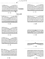
より詳細には、図4のように、4−1A、4−2A、のように網膜上面にコヒーレンスゲートを近づけたときに取得できる断層画像は、4−1B、4−2Bのようになる。しかし、4−3A、4−4Aのように網膜の中にコヒーレンスゲートが入ってしまった場合は、4−3B、4−4Bのような断層画像になってしまう。また、コヒーレンスゲートが4−5Aのように網膜を通り過ぎると4−5Bのように上下がさかさまの像になる。 More specifically, as shown in FIG. 4, tomographic images that can be acquired when the coherence gate is brought close to the upper surface of the retina like 4-1A and 4-2A are as shown in 4-1B and 4-2B. However, when a coherence gate enters the retina as in 4-3A and 4-4A, tomographic images such as 4-3B and 4-4B are obtained. When the coherence gate passes through the retina as in 4-5A, the image is turned upside down as in 4-5B.
これはFD型のOCT装置の特性としてコヒーレンスゲートからの距離しか判らないことが一因にある。従って、上記のようにコヒーレンスゲートが網膜の中にあると正しい断層画像が取れないため、コヒーレンスゲートが網膜の中にあるか外にあるかを的確に判断する必要がある。 This is because, as a characteristic of the FD type OCT apparatus, only the distance from the coherence gate is known. Therefore, since a correct tomographic image cannot be obtained when the coherence gate is in the retina as described above, it is necessary to accurately determine whether the coherence gate is in or outside the retina.
本発明によれば、後述するように、コヒーレンスゲートを網膜の外から網膜に近づけて行き、断層画像を取得する。このとき連続して取得できる2つの断層画像を比較すると、コヒーレンスゲートが網膜の外にあるときは、位置が変わるだけで断層画像の形状は変化しない。しかし、図5を参照して述べたように、コヒーレンスゲートが網膜の中にあると形状は大きく変化する。このことにより、連続して取得できる2つの断層画像の相互相関を計算し、即ち類似性を求め、この値が変化するとコヒーレンスゲートが網膜の中にあると判断することが出来る。 According to the present invention, a tomographic image is acquired by moving the coherence gate closer to the retina from outside the retina, as will be described later. Comparing two tomographic images that can be acquired continuously at this time, when the coherence gate is outside the retina, only the position changes and the shape of the tomographic image does not change. However, as described with reference to FIG. 5 , when the coherence gate is in the retina, the shape changes greatly. Thus, the cross-correlation between two tomographic images that can be acquired successively is calculated, that is, the similarity is obtained, and if this value changes, it can be determined that the coherence gate is in the retina.
図5に網膜での相互相関の値の例を示す、図5のように網膜の外にコヒーレンスゲートがある時は、同じ像であるため、相関は大きい値となる。網膜の内側にコヒーレンスゲートがある時は図5のように中心に行くに従い相関が少なくなり、次に中心をとおり過ぎると相関が増える。網膜をとおり過ぎると図4-5Bのように逆さまの像になるが、この時コヒーレンスゲートの変化に対して断層画像は変化しないため相関は大きい値となる。以上のように、網膜に、コヒーレンスゲートを近づけていき、連続して取得できる2つの断層画像の相互相関が変化する位置を見つける。この位置をコヒーレンスゲートが網膜の中に入りはじめた位置と判断し、1つ手間の位置にコヒーレンスゲートの位置を調整する。
また、図4では理解しやすいように2次元断層画像で説明したが、Aスキャン1つでも同様のことができる。
FIG. 5 shows an example of cross-correlation values in the retina. When the coherence gate is outside the retina as shown in FIG. 5, since the images are the same, the correlation is a large value. When there is a coherence gate inside the retina, the correlation decreases as it goes to the center as shown in FIG. 5, and then the correlation increases when it passes the center. When passing through the retina, the image becomes upside down as shown in FIG. 4-5B. At this time, the tomographic image does not change with respect to the change of the coherence gate, and the correlation becomes a large value. As described above, the coherence gate is brought closer to the retina to find a position where the cross-correlation between two tomographic images that can be acquired continuously changes. This position is determined as the position at which the coherence gate starts to enter the retina, and the position of the coherence gate is adjusted to a position between one hand.
In FIG. 4, the two-dimensional tomographic image is used for easy understanding, but the same can be done with one A scan.
[第1の実施例]
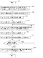
図1は、以上のコヒーレンスゲートと断層画像との関係を考慮して高解像度の3次元画像を取得するための、本発明の制御フローを示したフローチャートである。本発明を図1に従い説明する。まずステップ101で動作を開始する。フローが開始されると、初期化の操作としてコヒーレンスゲートを網膜から離れた初期位置に配置する。これは、通常人間の眼の眼軸長は大体20mmから30mmmであるため、眼の表面から、20mm以下くらいの位置に配置するとよい。
[First embodiment]
FIG. 1 is a flowchart showing a control flow of the present invention for acquiring a high-resolution three-dimensional image in consideration of the relationship between the coherence gate and the tomographic image. The present invention will be described with reference to FIG. First, in
次に、OCT像が取得できるまでコヒーレンスゲートを網膜にステップごとに近づける。なお、網膜像の取得はOCT像を目視でモニタする場合にはBスキャンが必要となる。しかし、自動で行う場合は、干渉信号が取得出来ればよいので1箇所のAスキャンでモニタすること可能であり、更にこの場合フーリエ変換も行う必要もない。干渉信号が取得できた段階で、OCTのBスキャン画像を取得する。この画像から、現在のコヒーレンスゲート位置から一番近い網膜の場所を特定し、その場所のXY座標を求め、求めた座標に測定光が照射されるようにXYスキャナを固定する。 Next, the coherence gate is moved closer to the retina step by step until an OCT image can be acquired. The acquisition of the retinal image requires a B scan when the OCT image is visually monitored. However, when it is performed automatically, it is only necessary to acquire an interference signal, so it is possible to monitor with one A scan, and in this case, it is not necessary to perform Fourier transform. When the interference signal is acquired, an OCT B-scan image is acquired. From this image, the location of the retina closest to the current coherence gate position is specified, the XY coordinates of the location are obtained, and the XY scanner is fixed so that the measurement light is irradiated to the obtained coordinates.
以上の操作を行った後、ステップ102として、ミラー206等を移動させることにより、コヒーレンスゲートの位置をXY座標に対応する第1の位置に配置する。コヒーレンスゲートの移動後、Aスキャン画像を取得することにより、第1の位置における第1の合波光の強度を取得する(ステップ103)。続いて、ステップ104において、コヒーレンスゲートを第1の位置から被検査物側の第2の位置に移動させる(コヒーレンスゲートを被検査物に近づける)。具体的には、コヒーレンスゲートを1ステップ網膜に近づける。コヒーレンスゲートを第2の位置に移動させた後、ステップ105において当該位置でのAスキャン画像を取得し、第2の合波光の強度を取得する。
After performing the above operation, in
なお、コヒーレンスゲートは、前述したようにミラー206の移動、OCT装置と被検査物との距離を変化させる等、光路長を変化させる種々の方法が存在するが、本発明ではこれらを種々の方法を含めコヒーレンスゲートを移動させる移動手段として定義する。より詳細には、当該移動手段は、測定光の光路長と参照光の光路長との差である光路長差に基づいてコヒーレンスゲートを移動させている。
As described above, there are various methods for changing the optical path length of the coherence gate, such as the movement of the
ステップ106で、今回ステップ105で取得したAスキャン像とその前のステップで取得したAスキャン像の相互相関を計算する。より詳細には、第1及び第2の合波光の強度の相関を示す値を取得する。続くステップ107では、該相関を示す値と所定値との比較を行い、第1の合波光の強度と今回の第2の合波光の強度との間で所定値以上の変化が生じたか否かを判断する。
In
なお、図5に示すように、コヒーレンスゲートが網膜の内側に存在し、ステップ107の操作の際に、第1の合波光の強度と第2の合波光の強度との比較も為される。例えば網膜の手前側からコヒーレンスゲートを1ステップずつ網膜に近づけている場合を考えると、コヒーレンスゲートが網膜に達する前の段階では相関を示す値は大きく変化しない。しかし、該コヒーレンスゲートが網膜の内側に入るとこの相関を示す値は小さくなり、網膜中央位置で最小となり、これより網膜の向こう側に位置するまで増加し、網膜も向こう側では一定の値となる。
As shown in FIG. 5, the coherence gate exists inside the retina, and the intensity of the first combined light and the intensity of the second combined light are also compared during the operation of
従って、この相関を示す値の変化の傾向とコヒーレンスゲートの初期位置を知ることにより、網膜において配置したい位置に対してコヒーレンスゲートを移動させる方向を特定することが可能となる。即ち、第1の位置で取得した第1の合波光と、第2の位置で取得した第2の合波光とに基づいてコヒーレンスゲートの移動方向を取得、決定することができる。本発明ではCPU210においてコヒーレンスゲートの移動方向を取得する移動方向取得手段として機能するモジュール領域により当該操作は実行される。また、このコヒーレンスゲートを第2の位置から移動させる移動手段の制御は、制御手段として機能するモジュール領域により実行される。この移動方向を適宜取得することにより、コヒーレンスゲートがある程度以上移動された後であっても、好適な位置へコヒーレンスゲート移動させるための適切な方向を適宜得ることが可能となる。
Therefore, by knowing the tendency of change in the value indicating the correlation and the initial position of the coherence gate, it is possible to specify the direction in which the coherence gate is moved with respect to the position to be arranged in the retina. That is, the moving direction of the coherence gate can be acquired and determined based on the first combined light acquired at the first position and the second combined light acquired at the second position. In the present invention, the operation is executed by the module area functioning as a movement direction acquisition means for acquiring the movement direction of the coherence gate in the
ここでフローに戻り、ステップ107において相関を示す値が所定値よりも大きい状態であれば、フローはステップ104に戻り、第2の位置よりも更に被検査物側の位置にコヒーレンスゲートを移動させる。即ち、相関を示す値が所定値より大きい場合に、コヒーレンスゲートを第2の位置から被検査物側の第3の位置に移動する必要があるため、移動方向取得手段はこの移動方向を取得する。更に、ステップ107において、該第3の位置で取得した被検査物の第3の合波光と第2の合波光との強度の相関に基づいてコヒーレンスゲートの移動方向を再度取得する操作を実行する。以下、ステップ107において相関を示す値が所定値以下となるまで当該操作は繰り返される。
ステップ107にて相関を示す値が所定値以下であると判断されると、フローはステップ108に移行する。ステップ108では、現在のコヒーレンスゲートの位置が最適位置を1ステップ越えた状態にあると考え、このコヒーレンスゲートの1つ前のステップ位置を最適な位置とする。
Returning to the flow, if the value indicating the correlation is larger than the predetermined value in
If it is determined in
本発明において、断層画像を生成する或いは取得する断層画像取得手段は、CPU210において合波光より断層画像或いは3次元画像を生成するモジュール領域に対応する。当該断層画像取得手段はこの1つ前のステップ位置にコヒーレンスゲートが存在する状態での合波光より3次元画像の生成等を実行する。即ち、移動手段によるコヒーレンスゲートの移動が終了したことに応じて、断層画像取得手段は被検査物の断層画像を取得する。
In the present invention, the tomographic image obtaining means or obtaining generates a tomographic image corresponds to the module fields to generate a tomographic image or 3-dimensional image from the combined light have you to
ここで、前述したコヒーレンスゲートの移動手段は移動方向取得手段により取得された移動方向に向けて該コヒーレンスゲートを移動させる。この移動手段の動作は、CPU210において、コヒーレンスゲートを第2の位置から移動方向取得手段で取得した移動方向に移動するように移動手段を制御する制御手段として機能するモジュール領域により実行される。
Here, the moving means of the coherence gate described above moves the coherence gate toward a direction of movement acquired by the movement direction acquisition unit. The operation of the moving means is executed by the
以上に述べた相互相関の計算方法として、例えば、2つの像の輝度等の強度の差の自乗平均根の逆数を求める方法がある。これは2つの像の強度をそれぞれA(x)、B(x)とすると求める相互相関は各点の強度の差A(x)−B(x)の2乗の総和をxの点の数(データ数)で割ったものの平方根の逆数で表される。また、通常は、片方の座標を変化させ、相関が一番大きいところを取るが、この場合、色素上皮層の反射光量が一番大きいことが知られているため、強度が一番大きい座標を基準にして相互相関を取ることで計算を早く行うことが出来る。 As a method of calculating the cross correlation described above, for example, there is a method of obtaining the reciprocal of the root mean square of the difference in intensity such as the luminance of two images. This means that when the intensities of two images are respectively A (x) and B (x), the cross-correlation to be obtained is the sum of the squares of the intensity differences A (x) −B (x) of the points, the number of points of x. It is expressed as the reciprocal of the square root of the value divided by (number of data). Usually, the coordinate of one side is changed to take the place where the correlation is the largest, but in this case, it is known that the amount of reflected light of the pigment epithelium layer is the largest. The calculation can be performed quickly by taking the cross-correlation as a reference.
この例では、相互相関を計算値の変化点があれば、すぐに網膜の内側であると判断したが、ノイズなど大きい場合は、変化点があっても、105、106の操作を複数回行い、計算値が増えていることを確認するとより精度よい判断を行うことができる。 In this example, if there is a change point in the calculated value of the cross-correlation, it is immediately determined that it is inside the retina. If it is confirmed that the calculated value is increased, more accurate determination can be made.
またこの例では、104で2次元の断層画像であるBスキャンを対象にしているが、3次元の断層画像を取得する場合は、ここで取得する断層画像を3次元にすることで対応できる。このことで、3次元の像の中で、現在のコヒーレンスゲート位置から一番近い網膜の場所を見つけ出すことができる。 In this example, the B scan, which is a two-dimensional tomographic image, is targeted at 104, but when a three-dimensional tomographic image is acquired, the tomographic image acquired here can be handled in three dimensions. This makes it possible to find the location of the retina closest to the current coherence gate position in the three-dimensional image.
なお、コヒーレンスゲートを予め被検査物の外側に配置して断層画像の撮像を実行する第1の撮像モードと、該コヒーレンスゲートを予め被検査物の内側に配置して断層画像の撮像を実行する第2の撮像モードを有する構成としても良い。前述したように、断層画像の撮像においては、コヒーレンスゲートの存在位置及びその近傍において最も好適な解像度の画像が得られる。例えば被検査物が人間の目の場合、網膜の表面側にある神経線維層の分析を詳細に為したい場合に対して、網膜の奥側にある色素上皮層の分析を詳細に為したい場合もある。神経線維層が対象の場合には、前述した実施例の如く網膜の手前側からコヒーレンスゲート移動させることで、短い時間であっても高解像度の神経線維層の3次元画像が得られる。 The first imaging mode in which the coherence gate is previously arranged outside the inspection object and the tomographic image is acquired, and the coherence gate is previously arranged inside the inspection object and the tomographic image is acquired. A configuration having the second imaging mode may be adopted. As described above, in tomographic imaging, an image with the most suitable resolution is obtained at the position where the coherence gate exists and in the vicinity thereof. For example, when the object to be inspected is a human eye, when you want to analyze the nerve fiber layer on the surface side of the retina in detail, you may want to analyze the pigment epithelium layer on the back side of the retina in detail. is there. When the nerve fiber layer is a target, a high-resolution three-dimensional image of the nerve fiber layer can be obtained even in a short time by moving the coherence gate from the front side of the retina as in the above-described embodiment.
しかし、色素上皮層が対象の場合には網膜手前から測定を開始すると測定にかなりの時間を要する。この場合、前述した第2の撮像モードにより、予め網膜内にコヒーレンスゲートを配置し、当該配置から網膜の向こう側に向かってコヒーレンスゲートを移動させることで、短時間で高解像度の色素上皮層の3次元画像を得ることが可能となる。また、神経線維層もその厚さ方向で表面側の情報が重要な場合或いは奥側の情報が重要な場合があり得るが、これらモードを適時選択することにより、より短時間で所望位置の画像を高解像度化することが可能となる。
However, in the case where the pigment epithelium layer is a subject , if the measurement is started from the front of the retina, a considerable time is required for the measurement. In this case, in the second imaging mode described above, a coherence gate is arranged in the retina in advance, and the coherence gate is moved from the arrangement toward the other side of the retina. A three-dimensional image can be obtained. In addition, information on the surface side in the thickness direction of the nerve fiber layer may be important or information on the back side may be important. However, by selecting these modes in a timely manner, an image of a desired position can be obtained in a shorter time. Can be increased in resolution.
本発明においては、このモード選択は、コヒーレンスゲートを被検査物の外側にして該被検査物の断層画像を撮る第1の撮像モードと、該コヒーレンスゲートを該被検査物の内側にして該被検査物の断層画像を撮る第2の撮像モードとを選択する選択手段により実行される。なお、この選択手段は、切換スイッチの態様にて操作者により選択可能としても良く、CPU210を介して選択可能としても良く、移動方向取得手段が、2つ合波光の相関を示す値に基づいて自動的にコヒーレンスゲートの移動方向を取得する態様としても良い。
In the present invention, this mode selection includes the first imaging mode in which a tomographic image of the inspection object is taken with the coherence gate outside the inspection object, and the inspection object with the coherence gate positioned inside the inspection object. This is executed by selection means for selecting a second imaging mode for taking a tomographic image of the inspection object. This selection means may be selectable by the operator in the form of a changeover switch, or may be selectable via the
なお、当該選択手段を付加した構成の場合、移動方向取得手段は2つの合波光と共にこの選択手段からの指令に基づいて、コヒーレンスゲートの移動方向を取得することを要する。
より詳細には、選択手段により第1の撮像モードが選択され且つ相関を示す値が所定値より小さい場合には、移動方向取得手段はコヒーレンスゲートを第2の位置から第1の位置側に移動する移動方向を取得する。
In the case where the selection unit is added, the movement direction acquisition unit needs to acquire the movement direction of the coherence gate based on a command from the selection unit together with the two combined lights.
More specifically, when the first imaging mode is selected by the selection unit and the correlation value is smaller than a predetermined value, the movement direction acquisition unit moves the coherence gate from the second position to the first position side. Get the direction to move.
また、選択手段により第2の撮像モードが選択され且つ相関を示す値が所定値より小さい場合には、移動方向取得手段はコヒーレンスゲートを第2の位置から前記被検査物側の第3の位置に移動する移動方向を取得し、第3の位置で取得した被検査物の第3の合波光と第2の合波光との強度の相関に基づいて再度コヒーレンスゲートの移動方向を取得する。なお、この場合、前述した被検査物の外側から好適なコヒーレンスゲートの位置を探索した場合とは異なり、相関が所定値より大きい場合にコヒーレンスゲートが第3の位置で被検査物中の好適な位置に存在していると判断される。従って、該被検査物の断層画像はコヒーレンスゲートの第3の位置で得られた第3の合波光に基づいて被検査物の断層画像を取得する。 Further, when the second imaging mode is selected by the selection unit and the value indicating the correlation is smaller than the predetermined value, the movement direction acquisition unit moves the coherence gate from the second position to the third position on the inspection object side. The movement direction of the coherence gate is acquired again based on the correlation between the intensity of the third combined light and the second combined light of the inspection object acquired at the third position. In this case, unlike the case where a suitable position of the coherence gate is searched from the outside of the inspection object described above, the coherence gate is preferably located in the inspection object at the third position when the correlation is larger than a predetermined value. It is determined to exist at the position. Therefore, the tomographic image of the inspection object is acquired based on the third combined light obtained at the third position of the coherence gate.
[第2の実施例]
図6は第2の実施例の制御フローを示したフローチャートである。第1の実施例ではステップ102で現在のコヒーレンスゲートに一番近い所を求めて当該位置を第1の位置としてコヒーレンスゲートを移動した後、合波光の強度の取得に続く以下のフローを実行している。
[Second Embodiment]
FIG. 6 is a flowchart showing a control flow of the second embodiment. In the first embodiment, after obtaining the closest position to the current coherence gate in
第2の実施例では、第1の位置を求める際に取得したOCT断層画像から求めた場所とコヒーレンスゲートからの距離を求め、この距離を用いて該第1の位置の手前までコヒーレンスゲートを移動させ、その後に第1の実施例と同様の処理を行う。 In the second embodiment, the distance from the coherence gate obtained from the OCT tomographic image obtained when obtaining the first position is obtained, and the coherence gate is moved to the front of the first position using this distance. Thereafter, the same processing as in the first embodiment is performed.
すなわち、ステップ501で上記現在のコヒーレンスゲートに一番近い所とコヒーレンスゲートの距離を求める。次にステップ502ではステップ501で求めた距離を用い、数ステップ手前までコヒーレンスゲートを上記一番近い所まで移動させる。
これらの前後の処理は実施例1と同じである。
このことにより、すばやく目的の位置までコヒーレンスゲートを移動させることが出来、処理が早く行うことが出来る。
That is, in
These processes before and after are the same as those in the first embodiment.
As a result, the coherence gate can be quickly moved to a target position, and processing can be performed quickly.
以上述べたように、本発明の一実施形態では、フーリエドメイン方式のOCT断層撮像装置の態様であって、コヒーレンスゲートの位置を調整する際、網膜の外からコヒーレンスゲートを近づけながら断層画像を取得し、連続して取得した2つの断層画像の相互相関を計算し、該相互相関の値が変化する手前のコヒーレンスゲートの位置を基準となる調整位置第1の位置としている。この場合、コヒーレンスゲートの近づけ方は一定間隔で行われることが好ましい。また、計測時間の短縮及びCPUの負荷軽減等の観点から、相互相関の計算を行う断層画像にはAスキャンの断層画像を用いることが好ましい。なお、この場合、本発明での相互相関の計算方法は、2つの断層画像の各座標におけるデータの自乗平均根の逆数としている。また、コヒーレンスゲートを近づけながら断層画像を取得する際、始めに取得できた断層画像により、コヒーレンスゲートに一番近い所を検出し、このところのAスキャンの断層画像を取得し、相互相関を計算するとより好ましい。更にこの場合には、コヒーレンスゲートに一番近い所を検出した後、該コヒーレンスゲートを検出したところの手前近傍までコヒーレンスゲートを移動し、そこから一定間隔でコヒーレンスゲートを網膜に近づけると良い。 As described above, according to one embodiment of the present invention, it is an aspect of a Fourier domain type OCT tomography apparatus, and when adjusting the position of a coherence gate, a tomographic image is acquired while bringing the coherence gate closer from the outside of the retina. Then, the cross-correlation between two successively acquired tomographic images is calculated, and the position of the coherence gate before the cross-correlation value changes is set as the reference adjustment position first position. In this case, it is preferable that the approach of the coherence gate is performed at regular intervals. Further, from the viewpoint of shortening the measurement time and reducing the load on the CPU, it is preferable to use an A-scan tomographic image as a tomographic image for calculating cross-correlation. In this case, the cross-correlation calculation method in the present invention uses the reciprocal of the root mean square of the data at each coordinate of the two tomographic images. In addition, when acquiring a tomographic image while bringing the coherence gate closer, the tomographic image that was acquired first detects the location closest to the coherence gate, acquires the A-scan tomographic image here, and calculates the cross-correlation It is more preferable. Further, in this case, after detecting the position closest to the coherence gate, the coherence gate is moved to the vicinity of where the coherence gate is detected, and then the coherence gate is moved closer to the retina at regular intervals.
[その他の実施例]
また、本発明は、以下の処理を実行することによっても実現される。即ち、上述した実施形態の機能を実現するソフトウェア(プログラム)を、ネットワーク又は各種記憶媒体を介してシステム或いは装置に供給し、そのシステム或いは装置のコンピュータ(またはCPUやMPU等)がプログラムを読み出して実行する処理である。
[Other Examples]
The present invention can also be realized by executing the following processing. That is, software (program) that realizes the functions of the above-described embodiments is supplied to a system or apparatus via a network or various storage media, and a computer (or CPU, MPU, or the like) of the system or apparatus reads the program. It is a process to be executed.
201 光源
202 ビームスプリッタ
203 XYスキャナ
204、208 レンズ
206 ミラー
207 回折格子
209 一次元センサ
210 CPU
217 光検出器
201
217 photodetector
Claims (18)
前記測定光の光路長と前記参照光の光路長との差である光路長差を変更する変更手段と、
第1の光路長差と前記第1の光路長差の絶対値よりも光路長差の絶対値が小さい第2の光路長差とでそれぞれ取得した第1及び第2の合波光を用いて、前記被検査物の第1及び第2の断層画像を取得する断層画像取得手段と、
前記第1及び第2の断層画像の類似性を示す値が所定値よりも大きい場合には前記光路長差の絶対値が前記第2の光路長差の絶対値より小さくなる方向を、前記類似性を示す値が所定値以下の場合には前記光路長差の絶対値が前記第2の光路長差の絶対値より大きくなる方向を、前記光路長差を変更する方向として取得する方向取得手段と、
前記第2の光路長差から前記取得された方向に前記光路長差を変更させるように前記変更手段を制御する制御手段と、
を有することを特徴とする撮像装置。 An imaging device that takes a tomographic image of the object to be inspected using a combined light obtained by combining the return light from the object irradiated with the measurement light and the reference light corresponding to the measurement light,
Changing means for changing an optical path length difference which is a difference between an optical path length of the measurement light and an optical path length of the reference light;
Using the first and second combined light obtained respectively by the first optical path length difference between the first absolute value second optical path length difference absolute value is smaller optical path length difference than the optical path length difference, Tomographic image acquisition means for acquiring first and second tomographic images of the inspection object;
When the value indicating the similarity between the first and second tomographic images is larger than a predetermined value , the absolute value of the optical path length difference becomes smaller than the absolute value of the second optical path length difference. absolute value and the second a larger direction than the absolute value of the optical path length difference, the direction obtaining means for obtaining a direction of changing the optical path length difference of the optical path length difference when the value indicating the sex is less than a predetermined value When,
Control means for controlling the changing means so as to change the optical path length difference in the acquired direction from the second optical path length difference;
An imaging device comprising:
前記方向取得手段は、前記選択手段での選択の結果及び前記第1及び第2の断層画像の前記類似性を示す値を用いて前記変更する方向を取得することを特徴とする請求項1乃至3のいずれか1項に記載の撮像装置。 A first imaging mode for taking a tomographic image of the inspection object in a state where the optical path length of the measurement light is longer than the optical path length of the reference light; and the optical path length of the measurement light is longer than the optical path length of the reference light A selection means for selecting a second imaging mode for taking a tomographic image of the inspection object in a short state;
The direction acquisition unit acquires the direction to be changed using a result of selection by the selection unit and a value indicating the similarity between the first and second tomographic images. 4. The imaging device according to any one of 3.
前記第2の撮像モードにおいて、前記類似性を示す値が前記所定値以下の場合には前記光路長差が前記第2の光路長差より短くなるように前記変更手段を制御すると共に、前記類似性を示す値が前記所定値よりも大きい場合には前記光路長差が前記第2の光路長差より長くなるように前記変更手段を制御することを特徴とする請求項4に記載の撮像装置。 In the first imaging mode, the control unit controls the changing unit so that the optical path length difference is shorter than the second optical path length difference when a value indicating the similarity is larger than the predetermined value. And when the value indicating the similarity is equal to or less than the predetermined value, the changing means is controlled so that the optical path length difference is longer than the second optical path length difference,
In the second imaging mode, when the value indicating the similarity is less than or equal to the predetermined value, the change unit is controlled so that the optical path length difference is shorter than the second optical path length difference, and the similarity 5. The imaging apparatus according to claim 4, wherein the change unit is controlled so that the optical path length difference is longer than the second optical path length difference when a value indicating the property is larger than the predetermined value. 6. .
前記測定光の光路長と前記参照光の光路長との差である光路長差を変更する変更手段と、
第1の光路長差と前記第1の光路長差の絶対値よりも光路長差の絶対値が小さい第2の光路長差とでそれぞれ取得した第1及び第2の合波光を用いて、前記被検査物の第1及び第2の断層画像を取得する断層画像取得手段と、
前記取得された第1の断層画像と前記取得された第2の断層画像との類似性を示す値が所定値よりも大きい場合には前記光路長差の絶対値が前記第2の光路長差の絶対値より小さくなるように、前記類似性を示す値が所定値以下の場合には前記光路長差の絶対値が前記第2の光路長差の絶対値より大きくなるように、前記変更手段を制御する制御手段と、
を有することを特徴とする撮像装置。 An imaging device that takes a tomographic image of the object to be inspected using a combined light obtained by combining the return light from the object irradiated with the measurement light and the reference light corresponding to the measurement light,
Changing means for changing an optical path length difference which is a difference between an optical path length of the measurement light and an optical path length of the reference light;
And we have use the first and second combined light obtained respectively by the first optical path length difference between the first absolute value second optical path length difference absolute value is smaller optical path length difference than the optical path length difference, Tomographic image acquisition means for acquiring first and second tomographic images of the inspection object;
When the value indicating the similarity between the acquired first tomographic image and the acquired second tomographic image is larger than a predetermined value , the absolute value of the optical path length difference is the second optical path length difference. The changing means so that the absolute value of the optical path length difference is larger than the absolute value of the second optical path length difference when the value indicating the similarity is equal to or smaller than a predetermined value so as to be smaller than the absolute value of the second optical path length. Control means for controlling
An imaging device comprising:
前記制御手段は、前記選択手段での選択の結果及び前記第1及び第2の断層画像の前記類似性を示す値を用いて前記変更手段を制御することを特徴とする請求項6又は7に記載の撮像装置。 A first imaging mode for taking a tomographic image of the inspection object in a state where the optical path length of the measurement light is longer than the optical path length of the reference light; and the optical path length of the measurement light is longer than the optical path length of the reference light A selection means for selecting a second imaging mode for taking a tomographic image of the inspection object in a short state;
It said control means to claim 6 or 7, wherein the controller controls the changing means with a value indicating the similarity of the result of selection in the selecting means and the first and second tomographic images The imaging device described.
前記第3の光路長差で取得した前記被検査物の第3の合波光を用いて得た第3の断層画像と、前記第2の断層画像との類似性を示す値を用いて、前記変更手段を制御することを特徴とする請求項8又は9に記載の撮像装置。 Wherein when the value indicating the second imaging mode is selected and before Symbol similarity by the selection means is greater than the predetermined value, the said optical path length difference from the second optical path length difference the Controlling the changing means to change to a third optical path length difference longer than the optical path length difference of 2;
Using a value indicating the similarity between the third tomographic image obtained using the third combined light of the inspection object acquired by the third optical path length difference and the second tomographic image, the imaging apparatus according to claim 8 or 9, characterized in that controlling the changing means.
前記断層画像取得手段は、前記第3の光路長差で取得した前記第3の合波光を用いて前記被検査物の断層画像を取得することを特徴とする請求項10に記載の撮像装置。 When the second imaging mode is selected by the selection unit and the value indicating the similarity is equal to or less than the predetermined value, the control unit calculates the optical path length difference from the second optical path length difference. Controlling the changing means to change to a third optical path length difference shorter than the optical path length difference of
The tomographic image obtaining means, before Symbol third image pickup apparatus according to claim 10, using the third multiplexed light obtained in the optical path length difference and acquires a tomographic image of the inspection object .
前記測定光の光路長と前記参照光の光路長との差である光路長差の第1の光路長差と前記第1の光路長差の絶対値よりも光路長差の絶対値が小さい第2の光路長差とでそれぞれ取得した第1及び第2の合波光を用いて、前記被検査物の第1及び第2の断層画像を取得する工程と、
前記第1及び第2の断層画像の類似性を示す値が所定値よりも大きい場合には前記光路長差の絶対値が前記第2の光路長差の絶対値より小さくなる方向を、前記類似性を示す値が所定値以下の場合には前記光路長差の絶対値が前記第2の光路長差の絶対値より大きくなる方向を、前記光路長差を変更する方向として取得する工程と、
前記第2の光路長差から前記取得された方向に前記光路長差を変更させる工程と、
を含むことを特徴とする撮像方法。 And return light from the object to be inspected that is irradiated with measuring light, and have use of the combined was multiplexed light and the reference light corresponding to the surveying constant light, an imaging method of taking a tomographic image obtaining step thereof,
The absolute value of the optical path length difference is smaller than the absolute value of the first optical path length difference of the optical path length difference that is the difference between the optical path length of the measurement light and the optical path length of the reference light. and have use the first and second combined light obtained respectively by the optical path length difference of 2, to obtain the first and second tomographic image of the inspection object process,
When the value indicating the similarity between the first and second tomographic images is larger than a predetermined value , the absolute value of the optical path length difference becomes smaller than the absolute value of the second optical path length difference. a step of acquiring a direction in which the absolute value is greater than the absolute value of the second optical path length difference of the optical path length difference, as the direction of changing the optical path length difference when the value indicating the sex is not more than a predetermined value,
Changing the optical path length difference in the acquired direction from the second optical path length difference;
An imaging method comprising:
前記測定光の光路長と前記参照光の光路長との差である光路長差の第1の光路長差と前記第1の光路長差の絶対値よりも光路長差の絶対値が小さい第2の光路長差とでそれぞれ取得した第1及び第2の合波光を用いて、前記被検査物の第1及び第2の断層画像を取得する工程と、
前記取得された第1の断層画像と前記取得された第2の断層画像との類似性を示す値が所定値よりも大きい場合には前記光路長差の絶対値が前記第2の光路長差の絶対値より小さくなるように、前記類似性を示す値が所定値以下の場合には前記光路長差の絶対値が前記第2の光路長差の絶対値より大きくなるように前記光路長差を変更する工程と、
を含むことを特徴とする撮像方法。 And return light from the object to be inspected that is irradiated with measuring light, and have use of the combined was multiplexed light and the reference light corresponding to the surveying constant light, an imaging method of taking a tomographic image obtaining step thereof,
The absolute value of the optical path length difference is smaller than the absolute value of the first optical path length difference of the optical path length difference that is the difference between the optical path length of the measurement light and the optical path length of the reference light. and have use the first and second combined light obtained respectively by the optical path length difference of 2, to obtain the first and second tomographic image of the inspection object process,
When the value indicating the similarity between the acquired first tomographic image and the acquired second tomographic image is larger than a predetermined value , the absolute value of the optical path length difference is the second optical path length difference. The optical path length difference so that the absolute value of the optical path length difference is larger than the absolute value of the second optical path length difference when the value indicating the similarity is equal to or smaller than a predetermined value so as to be smaller than the absolute value of the second optical path length. Changing the process,
An imaging method comprising:
Priority Applications (2)
| Application Number | Priority Date | Filing Date | Title |
|---|---|---|---|
| JP2012006009A JP6166509B2 (en) | 2012-01-16 | 2012-01-16 | Imaging apparatus and imaging method |
| US13/734,058 US9033498B2 (en) | 2012-01-16 | 2013-01-04 | Photographing apparatus and photographing method |
Applications Claiming Priority (1)
| Application Number | Priority Date | Filing Date | Title |
|---|---|---|---|
| JP2012006009A JP6166509B2 (en) | 2012-01-16 | 2012-01-16 | Imaging apparatus and imaging method |
Publications (3)
| Publication Number | Publication Date |
|---|---|
| JP2013144047A JP2013144047A (en) | 2013-07-25 |
| JP2013144047A5 JP2013144047A5 (en) | 2015-03-26 |
| JP6166509B2 true JP6166509B2 (en) | 2017-07-19 |
Family
ID=48779733
Family Applications (1)
| Application Number | Title | Priority Date | Filing Date |
|---|---|---|---|
| JP2012006009A Expired - Fee Related JP6166509B2 (en) | 2012-01-16 | 2012-01-16 | Imaging apparatus and imaging method |
Country Status (2)
| Country | Link |
|---|---|
| US (1) | US9033498B2 (en) |
| JP (1) | JP6166509B2 (en) |
Families Citing this family (3)
| Publication number | Priority date | Publication date | Assignee | Title |
|---|---|---|---|---|
| JP6444080B2 (en) * | 2014-07-14 | 2018-12-26 | キヤノン株式会社 | OCT apparatus and control method thereof |
| EP3127472B1 (en) | 2015-08-07 | 2019-10-09 | Canon Kabushiki Kaisha | Method and program for positioning an mage of an object on a tomogram and an optical coherence tomography apparatus therefor |
| US11166630B2 (en) * | 2017-01-28 | 2021-11-09 | Cylite Pty Ltd | Optical coherence metrology and tomography with improved registration |
Family Cites Families (9)
| Publication number | Priority date | Publication date | Assignee | Title |
|---|---|---|---|---|
| JP4996917B2 (en) * | 2006-12-26 | 2012-08-08 | 株式会社トプコン | Optical image measurement device and program for controlling optical image measurement device |
| JP4996918B2 (en) * | 2006-12-26 | 2012-08-08 | 株式会社トプコン | Optical image measurement device and program for controlling optical image measurement device |
| JP5255524B2 (en) * | 2008-07-04 | 2013-08-07 | 株式会社ニデック | Optical tomographic imaging device, optical tomographic image processing device. |
| JP5331395B2 (en) * | 2008-07-04 | 2013-10-30 | 株式会社ニデック | Optical tomography system |
| JP5415902B2 (en) * | 2009-10-27 | 2014-02-12 | 株式会社トプコン | Ophthalmic observation device |
| JP4916573B2 (en) | 2010-01-28 | 2012-04-11 | パナソニック株式会社 | Optical interference measurement method and optical interference measurement apparatus |
| JP5511437B2 (en) * | 2010-02-25 | 2014-06-04 | 株式会社ニデック | Optical tomography system |
| JP6039156B2 (en) * | 2010-06-08 | 2016-12-07 | キヤノン株式会社 | Image processing apparatus, image processing method, and program |
| JP5864910B2 (en) | 2010-07-16 | 2016-02-17 | キヤノン株式会社 | Image acquisition apparatus and control method |
-
2012
- 2012-01-16 JP JP2012006009A patent/JP6166509B2/en not_active Expired - Fee Related
-
2013
- 2013-01-04 US US13/734,058 patent/US9033498B2/en not_active Expired - Fee Related
Also Published As
| Publication number | Publication date |
|---|---|
| US9033498B2 (en) | 2015-05-19 |
| US20130182218A1 (en) | 2013-07-18 |
| JP2013144047A (en) | 2013-07-25 |
Similar Documents
| Publication | Publication Date | Title |
|---|---|---|
| JP6507615B2 (en) | Optical coherence tomography apparatus and program | |
| JP5901124B2 (en) | Imaging apparatus and control method thereof | |
| JP6057567B2 (en) | Imaging control apparatus, ophthalmic imaging apparatus, imaging control method, and program | |
| JP5483873B2 (en) | Optical tomographic imaging apparatus and optical tomographic imaging method | |
| JP5610706B2 (en) | Imaging apparatus and imaging method | |
| JP5685013B2 (en) | Optical tomographic imaging apparatus, control method therefor, and program | |
| JP5416577B2 (en) | Retinal function measuring device | |
| JP5790002B2 (en) | Ophthalmic imaging equipment | |
| JP6143422B2 (en) | Image processing apparatus and method | |
| US10244937B2 (en) | Image processing apparatus and image processing method | |
| JP6221516B2 (en) | Ophthalmic photographing apparatus and ophthalmic photographing program | |
| US9517007B2 (en) | Image processing apparatus, image processing method, and storage medium | |
| JP6624641B2 (en) | Ophthalmic equipment | |
| JP2018019771A (en) | Optical coherence tomography device and optical coherence tomography control program | |
| JP2017131550A (en) | Mage processing device and image processing method | |
| JP2022176282A (en) | Ophthalmologic apparatus and control method thereof | |
| JP2018186930A (en) | Ophthalmologic imaging apparatus | |
| JP6606846B2 (en) | OCT signal processing apparatus and OCT signal processing program | |
| JP6633468B2 (en) | Blood flow measurement device | |
| JP2018201858A (en) | Spectacle-wearing parameter acquisition apparatus, spectacle-wearing parameter acquisition method, and spectacle-wearing parameter acquisition program | |
| JP2016055122A (en) | Optical coherence tomography device, oct analysis processor and program | |
| JP6166509B2 (en) | Imaging apparatus and imaging method | |
| JP5990932B2 (en) | Ophthalmic tomographic imaging system | |
| JP6779674B2 (en) | OCT device | |
| JP5987355B2 (en) | Ophthalmic tomographic imaging system |
Legal Events
| Date | Code | Title | Description |
|---|---|---|---|
| RD05 | Notification of revocation of power of attorney |
Free format text: JAPANESE INTERMEDIATE CODE: A7425 Effective date: 20130701 |
|
| A621 | Written request for application examination |
Free format text: JAPANESE INTERMEDIATE CODE: A621 Effective date: 20150105 |
|
| A521 | Request for written amendment filed |
Free format text: JAPANESE INTERMEDIATE CODE: A523 Effective date: 20150206 |
|
| A977 | Report on retrieval |
Free format text: JAPANESE INTERMEDIATE CODE: A971007 Effective date: 20151019 |
|
| A131 | Notification of reasons for refusal |
Free format text: JAPANESE INTERMEDIATE CODE: A131 Effective date: 20151124 |
|
| A521 | Request for written amendment filed |
Free format text: JAPANESE INTERMEDIATE CODE: A523 Effective date: 20160122 |
|
| A131 | Notification of reasons for refusal |
Free format text: JAPANESE INTERMEDIATE CODE: A131 Effective date: 20160510 |
|
| A521 | Request for written amendment filed |
Free format text: JAPANESE INTERMEDIATE CODE: A523 Effective date: 20160705 |
|
| A131 | Notification of reasons for refusal |
Free format text: JAPANESE INTERMEDIATE CODE: A131 Effective date: 20161004 |
|
| A521 | Request for written amendment filed |
Free format text: JAPANESE INTERMEDIATE CODE: A523 Effective date: 20161205 |
|
| TRDD | Decision of grant or rejection written | ||
| A01 | Written decision to grant a patent or to grant a registration (utility model) |
Free format text: JAPANESE INTERMEDIATE CODE: A01 Effective date: 20170525 |
|
| A61 | First payment of annual fees (during grant procedure) |
Free format text: JAPANESE INTERMEDIATE CODE: A61 Effective date: 20170623 |
|
| R151 | Written notification of patent or utility model registration |
Ref document number: 6166509 Country of ref document: JP Free format text: JAPANESE INTERMEDIATE CODE: R151 |
|
| LAPS | Cancellation because of no payment of annual fees |