JP6166357B2 - Perfusion source identification system - Google Patents
Perfusion source identification system Download PDFInfo
- Publication number
- JP6166357B2 JP6166357B2 JP2015508980A JP2015508980A JP6166357B2 JP 6166357 B2 JP6166357 B2 JP 6166357B2 JP 2015508980 A JP2015508980 A JP 2015508980A JP 2015508980 A JP2015508980 A JP 2015508980A JP 6166357 B2 JP6166357 B2 JP 6166357B2
- Authority
- JP
- Japan
- Prior art keywords
- protrusions
- perfusion
- perfusion source
- port
- neck
- Prior art date
- Legal status (The legal status is an assumption and is not a legal conclusion. Google has not performed a legal analysis and makes no representation as to the accuracy of the status listed.)
- Active
Links
- 230000010412 perfusion Effects 0.000 title claims description 76
- 238000003384 imaging method Methods 0.000 claims description 21
- 210000005252 bulbus oculi Anatomy 0.000 description 19
- 239000012530 fluid Substances 0.000 description 8
- 239000007788 liquid Substances 0.000 description 8
- 238000001356 surgical procedure Methods 0.000 description 7
- 238000000034 method Methods 0.000 description 6
- 208000002177 Cataract Diseases 0.000 description 4
- 230000000007 visual effect Effects 0.000 description 4
- 239000013078 crystal Substances 0.000 description 3
- 238000010586 diagram Methods 0.000 description 3
- 238000001802 infusion Methods 0.000 description 3
- 230000007246 mechanism Effects 0.000 description 3
- 230000008901 benefit Effects 0.000 description 2
- 210000004087 cornea Anatomy 0.000 description 2
- 230000007423 decrease Effects 0.000 description 2
- 239000012634 fragment Substances 0.000 description 2
- 230000006870 function Effects 0.000 description 2
- 210000001525 retina Anatomy 0.000 description 2
- 239000004065 semiconductor Substances 0.000 description 2
- 239000002775 capsule Substances 0.000 description 1
- 230000007547 defect Effects 0.000 description 1
- 201000010099 disease Diseases 0.000 description 1
- 208000037265 diseases, disorders, signs and symptoms Diseases 0.000 description 1
- 210000001508 eye Anatomy 0.000 description 1
- 238000003973 irrigation Methods 0.000 description 1
- 230000002262 irrigation Effects 0.000 description 1
- 239000000463 material Substances 0.000 description 1
- 238000012986 modification Methods 0.000 description 1
- 230000004048 modification Effects 0.000 description 1
- 230000037361 pathway Effects 0.000 description 1
- 229920000642 polymer Polymers 0.000 description 1
- 239000000126 substance Substances 0.000 description 1
- 239000002699 waste material Substances 0.000 description 1
Images


Classifications
-
- G—PHYSICS
- G06—COMPUTING; CALCULATING OR COUNTING
- G06V—IMAGE OR VIDEO RECOGNITION OR UNDERSTANDING
- G06V10/00—Arrangements for image or video recognition or understanding
- G06V10/20—Image preprocessing
- G06V10/255—Detecting or recognising potential candidate objects based on visual cues, e.g. shapes
-
- A—HUMAN NECESSITIES
- A61—MEDICAL OR VETERINARY SCIENCE; HYGIENE
- A61F—FILTERS IMPLANTABLE INTO BLOOD VESSELS; PROSTHESES; DEVICES PROVIDING PATENCY TO, OR PREVENTING COLLAPSING OF, TUBULAR STRUCTURES OF THE BODY, e.g. STENTS; ORTHOPAEDIC, NURSING OR CONTRACEPTIVE DEVICES; FOMENTATION; TREATMENT OR PROTECTION OF EYES OR EARS; BANDAGES, DRESSINGS OR ABSORBENT PADS; FIRST-AID KITS
- A61F9/00—Methods or devices for treatment of the eyes; Devices for putting-in contact lenses; Devices to correct squinting; Apparatus to guide the blind; Protective devices for the eyes, carried on the body or in the hand
- A61F9/007—Methods or devices for eye surgery
-
- A—HUMAN NECESSITIES
- A61—MEDICAL OR VETERINARY SCIENCE; HYGIENE
- A61M—DEVICES FOR INTRODUCING MEDIA INTO, OR ONTO, THE BODY; DEVICES FOR TRANSDUCING BODY MEDIA OR FOR TAKING MEDIA FROM THE BODY; DEVICES FOR PRODUCING OR ENDING SLEEP OR STUPOR
- A61M1/00—Suction or pumping devices for medical purposes; Devices for carrying-off, for treatment of, or for carrying-over, body-liquids; Drainage systems
-
- G—PHYSICS
- G06—COMPUTING; CALCULATING OR COUNTING
- G06V—IMAGE OR VIDEO RECOGNITION OR UNDERSTANDING
- G06V10/00—Arrangements for image or video recognition or understanding
- G06V10/40—Extraction of image or video features
- G06V10/44—Local feature extraction by analysis of parts of the pattern, e.g. by detecting edges, contours, loops, corners, strokes or intersections; Connectivity analysis, e.g. of connected components
-
- A—HUMAN NECESSITIES
- A61—MEDICAL OR VETERINARY SCIENCE; HYGIENE
- A61G—TRANSPORT, PERSONAL CONVEYANCES, OR ACCOMMODATION SPECIALLY ADAPTED FOR PATIENTS OR DISABLED PERSONS; OPERATING TABLES OR CHAIRS; CHAIRS FOR DENTISTRY; FUNERAL DEVICES
- A61G13/00—Operating tables; Auxiliary appliances therefor
- A61G13/10—Parts, details or accessories
- A61G13/101—Clamping means for connecting accessories to the operating table
-
- A—HUMAN NECESSITIES
- A61—MEDICAL OR VETERINARY SCIENCE; HYGIENE
- A61G—TRANSPORT, PERSONAL CONVEYANCES, OR ACCOMMODATION SPECIALLY ADAPTED FOR PATIENTS OR DISABLED PERSONS; OPERATING TABLES OR CHAIRS; CHAIRS FOR DENTISTRY; FUNERAL DEVICES
- A61G13/00—Operating tables; Auxiliary appliances therefor
- A61G13/10—Parts, details or accessories
- A61G13/102—Fluid drainage means for collecting bodily fluids from the operating table, e.g. for blood, urine
-
- A—HUMAN NECESSITIES
- A61—MEDICAL OR VETERINARY SCIENCE; HYGIENE
- A61G—TRANSPORT, PERSONAL CONVEYANCES, OR ACCOMMODATION SPECIALLY ADAPTED FOR PATIENTS OR DISABLED PERSONS; OPERATING TABLES OR CHAIRS; CHAIRS FOR DENTISTRY; FUNERAL DEVICES
- A61G2205/00—General identification or selection means
- A61G2205/40—General identification or selection means by shape or form, e.g. by using shape recognition
-
- A—HUMAN NECESSITIES
- A61—MEDICAL OR VETERINARY SCIENCE; HYGIENE
- A61J—CONTAINERS SPECIALLY ADAPTED FOR MEDICAL OR PHARMACEUTICAL PURPOSES; DEVICES OR METHODS SPECIALLY ADAPTED FOR BRINGING PHARMACEUTICAL PRODUCTS INTO PARTICULAR PHYSICAL OR ADMINISTERING FORMS; DEVICES FOR ADMINISTERING FOOD OR MEDICINES ORALLY; BABY COMFORTERS; DEVICES FOR RECEIVING SPITTLE
- A61J1/00—Containers specially adapted for medical or pharmaceutical purposes
- A61J1/05—Containers specially adapted for medical or pharmaceutical purposes for collecting, storing or administering blood, plasma or medical fluids ; Infusion or perfusion containers
- A61J1/10—Bag-type containers
-
- A—HUMAN NECESSITIES
- A61—MEDICAL OR VETERINARY SCIENCE; HYGIENE
- A61M—DEVICES FOR INTRODUCING MEDIA INTO, OR ONTO, THE BODY; DEVICES FOR TRANSDUCING BODY MEDIA OR FOR TAKING MEDIA FROM THE BODY; DEVICES FOR PRODUCING OR ENDING SLEEP OR STUPOR
- A61M2205/00—General characteristics of the apparatus
- A61M2205/60—General characteristics of the apparatus with identification means
- A61M2205/6036—General characteristics of the apparatus with identification means characterised by physical shape, e.g. array of activating switches
-
- A—HUMAN NECESSITIES
- A61—MEDICAL OR VETERINARY SCIENCE; HYGIENE
- A61M—DEVICES FOR INTRODUCING MEDIA INTO, OR ONTO, THE BODY; DEVICES FOR TRANSDUCING BODY MEDIA OR FOR TAKING MEDIA FROM THE BODY; DEVICES FOR PRODUCING OR ENDING SLEEP OR STUPOR
- A61M2205/00—General characteristics of the apparatus
- A61M2205/60—General characteristics of the apparatus with identification means
- A61M2205/6063—Optical identification systems
-
- A—HUMAN NECESSITIES
- A61—MEDICAL OR VETERINARY SCIENCE; HYGIENE
- A61M—DEVICES FOR INTRODUCING MEDIA INTO, OR ONTO, THE BODY; DEVICES FOR TRANSDUCING BODY MEDIA OR FOR TAKING MEDIA FROM THE BODY; DEVICES FOR PRODUCING OR ENDING SLEEP OR STUPOR
- A61M3/00—Medical syringes, e.g. enemata; Irrigators
- A61M3/02—Enemata; Irrigators
- A61M3/0202—Enemata; Irrigators with electronic control means or interfaces
-
- Y—GENERAL TAGGING OF NEW TECHNOLOGICAL DEVELOPMENTS; GENERAL TAGGING OF CROSS-SECTIONAL TECHNOLOGIES SPANNING OVER SEVERAL SECTIONS OF THE IPC; TECHNICAL SUBJECTS COVERED BY FORMER USPC CROSS-REFERENCE ART COLLECTIONS [XRACs] AND DIGESTS
- Y10—TECHNICAL SUBJECTS COVERED BY FORMER USPC
- Y10S—TECHNICAL SUBJECTS COVERED BY FORMER USPC CROSS-REFERENCE ART COLLECTIONS [XRACs] AND DIGESTS
- Y10S128/00—Surgery
- Y10S128/24—Medical-surgical bags
Description
優先権の主張
本出願は、発明者Gary Sorensen、Alex Artsyukhovich、Raphael Gordon、Mike Morgan、Daniel Wilsonらによる、2012年4月26日に出願された、米国特許出願第13/456,294号、名称「IRRIGATION SOURCE IDENTIFICATION SYSTEM」の優先権の利益を主張するものであり、あたかも本明細書に完全かつ十分に記載されているかのように、参照によりその全体が本明細書に組み込まれる。
Priority Claim This application is entitled US Patent Application No. 13 / 456,294, filed April 26, 2012, by inventors Gary Sorensen, Alex Artsykhovich, Raphael Gordon, Mike Morgan, Daniel Wilson et al. It claims the benefit of the priority of “IRRIGATION SOURCE IDENTIFICATION SYSTEM” and is hereby incorporated by reference in its entirety as if it had been fully and fully described herein.
本発明は、水晶体超音波乳化吸引術に関し、より具体的には、手術中に使用される灌流源の種類を識別するためのシステムに関する。 The present invention relates to phacoemulsification, and more particularly to a system for identifying the type of perfusion source used during surgery.
ヒトの眼球は、角膜と呼ばれる透明な外側部分を通して光を伝達することによって、および水晶体を経由して像を網膜上に合焦させることによって、視覚を提供するように機能する。合焦させた像の質は、眼球のサイズおよび形状、ならびに角膜および水晶体の透明度を含む数多くの要因に依存する。年齢または疾患によって、水晶体の透明度が低下してくると、網膜に伝達することができる光が減少するので、視覚が低下する。こうした眼球の水晶体における欠陥は、医学的には、白内障として知られている。この状態に対する一般に認められている治療法は、水晶体を外科的に除去し、水晶体の機能を人工眼内水晶体(IOL)によって置き換えることである。 The human eyeball functions to provide vision by transmitting light through a transparent outer part called the cornea and by focusing the image on the retina via the lens. The quality of the focused image depends on a number of factors including the size and shape of the eyeball and the transparency of the cornea and lens. As the transparency of the lens decreases with age or disease, vision decreases because less light can be transmitted to the retina. Such defects in the lens of the eyeball are medically known as cataracts. The accepted treatment for this condition is to surgically remove the lens and replace the function of the lens with an artificial intraocular lens (IOL).
米国において、白内障水晶体の大部分は、水晶体超音波乳化吸引術と呼ばれる外科的手法によって除去される。水晶体超音波乳化吸引手技に好適な代表的な外科用ハンドピースは、超音波駆動の水晶体超音波乳化吸引ハンドピース、灌流スリーブによって囲まれる付属の中空角針、および電子制御コンソールから成る。ハンドピースアセンブリは、電気ケーブルおよび可撓管によって制御コンソールに取り付けられる。コンソールは、電気ケーブルを通して、ハンドピースによって付属の角針に伝達される電力レベルを変動させる。可撓管は、ハンドピースアセンブリを通して、手術部位に灌流液を供給し、また、眼球から吸引液を吸い込む。 In the United States, most of the cataractous lens is removed by a surgical technique called phacoemulsification. A typical surgical handpiece suitable for the phacoemulsification aspiration procedure consists of an ultrasonically driven phacoemulsification aspiration handpiece, an attached hollow square needle surrounded by a perfusion sleeve, and an electronic control console. The handpiece assembly is attached to the control console by an electrical cable and a flexible tube. The console varies the power level transmitted through the electrical cable by the handpiece to the attached square needle. The flexible tube supplies perfusate through the handpiece assembly to the surgical site and draws inhalation fluid from the eyeball.
代表的なハンドピースにおける動作部は、1組の圧電性結晶に直接取り付けられる、中央に位置する中空の共振棒材または角材である。結晶は、コンソールによって制御され、水晶体超音波乳化吸引術中に、角材および付属の角針の双方を駆動するために必要な、必要とされる超音波振動を供給する。結晶/角材アセンブリは、ハンドピースの中空本体またはシェル内で可撓性取り付け具によって吊設される。ハンドピース本体は、本体の遠位端部の縮径部分またはノーズコーンで終端する。一般的に、ノーズコーンは、中空灌流スリーブを受けるために雄ねじ付きであり、該雄ねじは、角針の大部分の長さを囲む。同様に、角材孔は、角針先端部の雄ねじを受けるためにその遠位端部で雌ねじ付きである。灌流スリーブも、ノーズコーンの雄ねじ上へねじ込まれる、雌ねじ付きの孔を有する。角針は、その先端部が、灌流スリーブの開口端部を過ぎて所定量だけ突出するように調整される。 The working part of a typical handpiece is a centrally located hollow resonant bar or square that is directly attached to a set of piezoelectric crystals. The crystal is controlled by the console and provides the necessary ultrasonic vibrations necessary to drive both the square and the attached square needle during phacoemulsification. The crystal / slab assembly is suspended by a flexible fixture within the hollow body or shell of the handpiece. The handpiece body terminates in a reduced diameter portion or nose cone at the distal end of the body. In general, the nose cone is externally threaded to receive a hollow perfusion sleeve that surrounds the length of the majority of the square needle. Similarly, the square hole is internally threaded at its distal end to receive the external thread of the square needle tip. The perfusion sleeve also has a female threaded hole that is screwed onto the male thread of the nose cone. The square needle is adjusted so that its tip protrudes a predetermined amount past the open end of the perfusion sleeve.
水晶体超音波乳化吸引手技中に、角針の先端部および灌流スリーブの端部は、眼球の外側組織における小さい切開部を通して、眼球の前嚢の中へ挿入される。外科医は、角針の先端部を眼球の水晶体と接触させ、よって、振動先端部が水晶体を破砕する。結果として生じる破片は、手技中に眼球に提供される灌流溶液とともに、角針の内部孔を通して眼球から廃棄物貯蔵容器の中へ吸引される。 During the phacoemulsification aspiration procedure, the tip of the square needle and the end of the perfusion sleeve are inserted through a small incision in the outer tissue of the eyeball into the anterior capsule of the eyeball. The surgeon brings the tip of the square needle into contact with the lens of the eyeball, so that the vibrating tip breaks the lens. The resulting debris is aspirated from the eyeball into the waste storage container through the internal hole of the square needle, along with the perfusion solution provided to the eyeball during the procedure.
手技の全体を通して、灌流液は、眼球の中へ導かれ、灌流スリーブと角針との間を通過し、そして、灌流スリーブの先端部でおよび/または灌流スリーブのその端部近くの1つ以上のポートまたは開口から眼球の中へと出て行く。灌流液は、超音波角針を振動させることによって発生する熱から眼球組織を保護する。さらに、灌流液は、眼球からの吸引のために、乳化した水晶体の破片を懸濁させる。 Throughout the procedure, the perfusate is guided into the eyeball, passes between the perfusion sleeve and the square needle, and / or at the tip of the perfusion sleeve and / or near that end of the perfusion sleeve. Go out from the port or opening into the eyeball. The perfusate protects the ocular tissue from the heat generated by vibrating the ultrasonic square needle. In addition, the perfusate suspends the emulsified lens fragments for aspiration from the eye.
灌流液は、一般的に、点滴液と同じように、瓶またはバッグで保持される。瓶またはバッグは、手術中に使用するために、液源を可撓管に接続するようにスパイクが挿入される端部を有する。いくつかの場合では、外科的手技中に、異なる種類、源、または量の灌流液が使用され得る。例えば、一方の灌流液源がある量の液を含み得る一方で、もう一方の源が異なる量の液を含む。液の化学的構造は、異なり得る。さらに、液を保持する瓶またはバックの種類も異なり得るか、または固有の特徴を有し得る。灌流液源の中での違いを検出する、自動的な方法を有することが望ましくなり得る。 Perfusate is generally held in a bottle or bag, just like infusion. The bottle or bag has an end into which a spike is inserted to connect the fluid source to the flexible tube for use during surgery. In some cases, different types, sources, or amounts of perfusate may be used during the surgical procedure. For example, one perfusate source may contain a certain amount of fluid while the other source contains a different amount of fluid. The chemical structure of the liquid can vary. In addition, the type of bottle or bag that holds the liquid may be different or may have unique characteristics. It may be desirable to have an automatic method of detecting differences among the perfusate sources.
本発明の原理と一致する一実施形態において、本発明は、ある量の灌流液を保持するための容器と、容器に流体連結されるポートとを備える、灌流源である。ポートは、出口端部と、首部とを有する。首部は、一群の突出部から選択される複数の突出部を有する。複数の突出部は、容器のための固有の識別子を提供する。 In one embodiment consistent with the principles of the present invention, the present invention is a perfusion source comprising a container for holding a volume of perfusate and a port fluidly connected to the container. The port has an exit end and a neck. The neck has a plurality of protrusions selected from a group of protrusions. The plurality of protrusions provide a unique identifier for the container.
本発明の別の実施形態において、本発明は、灌流源と、撮像デバイスと、プロセッサとを備える、灌流源識別システムである。灌流源は、ある量の灌流液を保持するための容器と、容器に流体連結されるポートとを含む。ポートは、出口端部と、首部とを有する。首部は、一群の突出部から選択される複数の突出部を有する。複数の突出部は、容器のための固有の識別子を提供する。撮像デバイスは、灌流源の首部に隣接して位置する。プロセッサは、撮像デバイスに連結される。撮像デバイスは、灌流源の首部および複数の突出部を撮像し、プロセッサは、どの識別子が画像と関連付けられるのかを判定する。 In another embodiment of the present invention, the present invention is a perfusion source identification system comprising a perfusion source, an imaging device, and a processor. The perfusion source includes a container for holding a volume of perfusate and a port fluidly connected to the container. The port has an exit end and a neck. The neck has a plurality of protrusions selected from a group of protrusions. The plurality of protrusions provide a unique identifier for the container. The imaging device is located adjacent to the neck of the perfusion source. The processor is coupled to the imaging device. The imaging device images the neck and the plurality of protrusions of the perfusion source, and the processor determines which identifier is associated with the image.
上述の概要および以下の詳細な説明は、いずれも例示的かつ説明的なものに過ぎず、請求されている本発明のさらなる説明を提供することを意図したものであると理解されたい。以下の説明、ならびに本発明の実践は、本発明の追加的な利点および目的を記載し、提案する。 It is to be understood that both the foregoing summary and the following detailed description are exemplary and explanatory only and are intended to provide further explanation of the claimed invention. The following description, as well as the practice of the present invention, describes and proposes additional advantages and objects of the present invention.
本明細書に組み込まれ、本明細書の一部を構成する添付図面は、本発明の複数の実現形態を例示し、説明とともに本発明の原理を説明する役目をする。 The accompanying drawings, which are incorporated in and constitute a part of this specification, illustrate multiple implementations of the invention and together with the description serve to explain the principles of the invention.
以下、本発明の例示的な実施形態を詳細に参照し、それらの実施例を添付図面に例示する。可能な限り、図面全体を通して、同じまたは類似の部品を指すように同じ参照番号が使用される。 Reference will now be made in detail to exemplary embodiments of the invention, examples of which are illustrated in the accompanying drawings. Wherever possible, the same reference numbers will be used throughout the drawings to refer to the same or like parts.
図1は、水晶体超音波乳化吸引術システムの液経路における構成要素の図である。図1は、白内障手術中に、眼球1145を通る液経路を表す。構成要素は、灌流液源1105と、灌流圧力センサ1130と、灌流弁1135と、灌流線1140と、ハンドピース1150と、吸引線1155と、吸引圧力センサ1160と、通気弁1165と、ポンプ1170と、貯蔵容器1175と、排液バッグ1180とを含む。灌流線1140は、白内障手術中に、灌流液を眼球1145に提供する。吸引線1155は、白内障手術中に、眼球から液および乳化した水晶体の小片を除去する。
FIG. 1 is a diagram of components in the liquid path of a phacoemulsification system. FIG. 1 represents the fluid path through the
灌流液が灌流液源1105を出るときに、該灌流液は、灌流線1140を通って眼球1145の中へ進行する。灌流圧力センサ1130は、灌流線1140の中の灌流液の圧力を測定する。また、灌流のオン/オフ制御のために、随意の灌流弁1135も提供される。灌流圧力センサ1130は、いくつかの市販の液圧センサのいずれかによって実現され、灌流液経路の中のどこかに(灌流源1105と眼球1145との間のどこかに)位置させることができる。
As the perfusate exits the
ハンドピース1150は、水晶体超音波乳化吸引手技中に、眼球1145の中に配置される。ハンドピース1150は、疾患した水晶体を突き破るために眼球の中で超音波振動する、(図2で見られるような)中空針を有する。針の周囲に位置するスリーブは、灌流線1140から灌流液を提供する。灌流液は、(図2Aでより明らかに示されるように)針の外側とスリーブの内側との間の空間を通過する。液および水晶体の小片は、中空針を通して吸引される。この様式で、中空針の内部通路は、吸引線1155に流体連結される。ポンプ1170は、眼球1145から吸引された液を吸い込む。吸引圧力センサ1160は、吸引線の圧力を測定する。ポンプ1170によって作成される真空を通気するために、随意の通気弁を使用することができる。吸引された液は、貯蔵容器1175を通過して排液バッグ1180に入る。
図2は、本発明の原理による識別特徴を有する灌流源の斜視図である。図2において、灌流バッグ200は、出口ポート210を有する。バッグ200は、ポリマー等の任意の可撓性材料で作製され得る。バッグ200は、点滴ポールから懸下されるように構成され得るか、またはバッグ200の内容物を加圧する圧搾機構とともに使用され得る。ポート210は、バッグ200の中の液のための出口を提供し、下でさらに詳細に説明される。
FIG. 2 is a perspective view of a perfusion source having identification features in accordance with the principles of the present invention. In FIG. 2, the
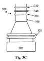
図3A〜3Cは、本発明の原理による灌流液源のポート端部の図である。図3Aにおいて、ポート300は、スパイクポート310と、位置合わせ特徴320と、首部360に位置する突出部330および340とを含む。スパイクポート310は、管を灌流バッグの内容物と流体接続する点滴スパイクを受ける。このように、スパイクポートは、灌流バッグの内容物を封止する。位置合わせ特徴320は、突出部330および340を撮像することができるように、首部360を特定の場所に配置する役割を果たす。
3A-3C are port end views of a perfusate source according to the principles of the present invention. In FIG. 3A,
突出部330および340は、灌流源の内容物を識別する役割を果たす。本発明の一実施形態では、灌流源の内容物を判定するために、突出部330と340との間の距離または間隔を検出することができる。例えば、図3Aで示されるように突出部330および340が互いに接近している場合、そのような接近した間隔は、灌流源の内容物を判定するために使用することができる。図3Bで示されるように、突出部330と340の間の距離または間隔は、図3Aで表されるものよりも大きい。この様式において、図3Bで示されるより大きい間隔は、灌流源の異なる内容物を示すために使用することができる。この様式において、2つの突出部330および340は、それらが付属する灌流源の内容物を示す、それらの間の距離または間隔を伴って使用され得る。例えば、突出部330と340との間の距離は、図3Aで1センチメートルであり、図3Bで3センチメートルであり得る。1センチメートルの距離から10センチメートルの距離まで1センチメートルずつ異なる距離を突出部330および340に提供する等の、数多くの他の距離も同様に利用され得る。この様式では、10個の異なる固有の識別子が提供される。別の例において、図3Aの突出部330および340は、2センチメートルの間隔の距離であり、図3Bの突出部330および340は、6センチメートルの間隔の距離であり、2つの固有の識別子を提供する。2つの突出部を使用するとき、それらの間の距離は、それらが付属する灌流源の内容物を示すことができる。
本発明の別の実施形態において、図3Cで示される灌流源の内容物を判定するために、いくつかの突出部330、340、および350が使用され得る。この様式において、3つの突出部330、340、および350は、ポートが付属する灌流源の内容物の指示を提供する。図3Aおよび3Bで示される2つの突出部は、存在する突出部の数に基づいて、それぞれ、異なる識別子を提供し得る。そのような識別子を提供するために、任意の数の突出部が使用され得る。例えば、6つの異なる識別子を提供するために1つ〜6つの突出部が使用され得る。加えて、突出部のないものも識別子であり得る。
In another embodiment of the invention,
本発明の他の実施形態において、固有の識別子を提供するために、突出部の形状、突出部が首部360から延在する距離、突出部の色、または他の視覚的違いが使用され得る。この様式において、単一の視覚的違いまたは視覚的違いの組み合わせが使用され得る。図3A〜3Cにおいて、突出部330および340は、首部360の外周の周囲に位置する円周方向の突条である。
In other embodiments of the invention, the shape of the protrusion, the distance that the protrusion extends from the
最後に、識別子を提供するために、上の視覚的違いの任意の組み合わせが利用され得る。例えば、識別子を提供するために、1つは、突出部の数、ならびに突出部間の距離または間隔を使用し得る。この様式において、図3Aの突出部330および340は、図3Cの突出部330、340、および350よりも双方が互いに接近し、数が異なる。灌流源のためのより多数の固有の識別子を提供するために、突出部の数および突出部間の距離の組み合わせを使用することができる。使用する突出部の種類に関係なく、固有の識別子は、一群の突出部のサブセットによって表され得る。
Finally, any combination of the above visual differences can be utilized to provide an identifier. For example, to provide an identifier, one may use the number of protrusions, as well as the distance or spacing between protrusions. In this manner,
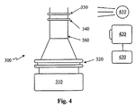
図4は、本発明の原理による灌流源識別システムの図である。図4において、ポート300は、光源410および撮像デバイス420に隣接して位置する。撮像デバイス420は、プロセッサ430に連結される。撮像デバイス420は、どの識別子が提示されているのかを判定するために、首部360、ならびに突出部330および340を撮像する。識別子は、ポート300が付属する灌流源の内容物を判定する。光源410は、最も一般的には、発光ダイオードまたはダイオードアレイであるが、他のよく見られる光源も利用され得る。本発明の別の実施形態では、周囲光または室内に存在する光が使用され得、その場合、光源410は存在しない。本発明の他の実施形態において、光源410は、撮像デバイス420に隣接して、撮像デバイス420の反対側に、または首部360を照明するように首部360に隣接して位置する。撮像デバイス420は、最も一般的には、CMOS型のカメラチップであるが、他の小型撮像デバイスも利用され得る。例えば、撮像デバイスは、CCD型のチップまたは他の半導体もしくはウエハ載置デバイスであり得る。プロセッサ430は、いくつかの異なるマイクロプロセッサ、マイクロコントローラ、ASIC、または専用半導体のいずれかであり得る。
FIG. 4 is a diagram of a perfusion source identification system according to the principles of the present invention. In FIG. 4, the
図5は、本発明の原理による灌流源識別システムとともに使用する位置合わせおよび挟持機構である。図5において、挟持デバイス510は、外科コンソールの中の適所でポート300を保持する。挟持デバイス510はまた、首部360を撮像する(および随意に照明する)ことができるように、該首部を適切に位置合わせする役割を果たす。挟持デバイス510は、ポート300を位置合わせ特徴320とスパイクポート310との間で自動的に掴むように、最も一般的には、電動化される。各灌流源が同じ位置合わせ特徴320およびスパイクポート310を有するので、灌流源の一貫した配置および首部360の位置合わせが達成される。他の実施形態において、挟持デバイスは、手動または手動の態様を有することができる。例えば、挟持デバイス510上の溝は、ポート300の位置合わせ特徴320およびスパイクポート310と位置合わせし得る。本発明の一実施形態において、挟持デバイス510は、水晶体超音波乳化吸引術コンソール(図示せず)の中に位置する。灌流源のポート300は、コンソールの中に位置するカラーの中に配置され得る。よって、挟持デバイス510は、適所でポート300(および付属の灌流源)を保持し得る。
FIG. 5 is an alignment and clamping mechanism for use with a perfusion source identification system according to the principles of the present invention. In FIG. 5, the
動作中に、ポート300は、ポート300の保持および首部360の位置合わせの双方を行う挟持デバイスの中へ配置される。灌流源の首部360は、撮像デバイス420が該首部を撮像することができるように位置合わせされる。首部360は、随意に照明される。撮像デバイス420は、首部360、ならびに突出部330および340を撮像する。撮像デバイス420によって撮像した画像は、突出部330および340がどの識別子を表しているのかを判定するために、メモリに記憶されている画像と比較される。そのような比較は、コントラスト、色、シャープネス、または他の画像属性に基づいて行われ得、また、プロセッサ430によって行われ得る。
In operation, the
上の説明から、本発明が、灌流源を識別するための改善されたシステムを提供することが認識され得る。本発明は、撮像システムによって識別することができるポート特徴を有する灌流源を提供する。本発明は、実施例によって本明細書で例示され、当業者によって種々の修正が行われ得る。 From the above description, it can be appreciated that the present invention provides an improved system for identifying perfusion sources. The present invention provides a perfusion source having a port feature that can be identified by an imaging system. The present invention is illustrated herein by way of example, and various modifications can be made by those skilled in the art.
当業者には、本明細書を考慮し、本明細書で開示される本発明を実行することによって、他の実施形態が明らかになるであろう。仕様および実施例は、例示的なものに過ぎず、本発明の真の範囲および精神は、以下の特許請求の範囲によって示されることを意図している。 Other embodiments will be apparent to those skilled in the art from consideration of the specification and practice of the invention disclosed herein. The specifications and examples are illustrative only and the true scope and spirit of the invention is intended to be indicated by the following claims.
Claims (13)
ある量の灌流液を保持するための容器と、
前記容器に流体連結されるポートと、を備え、前記ポートは、首部、位置合わせ特徴およびスパイクポートを含み、前記首部は、一群の突出部から選択される複数の突出部を有し、前記複数の突出部は、前記容器のための固有の識別子を提供し、前記位置合わせ特徴および前記スパイクポートは該位置合わせ特徴と該スパイクポートとの間に環状間隙を形成するように構成され、該環状間隙は、前記複数の突出部が撮像デバイスに位置合わせされるように狭持デバイスを受容するように構成される、
灌流源。 A container for holding a volume of perfusate as a perfusion source;
And a port that is fluidly connected to said container, said port neck includes an alignment feature and spike port, said neck portion has a plurality of protrusions are selected from a group of protrusions, wherein A plurality of protrusions provide a unique identifier for the container, and the alignment feature and the spike port are configured to form an annular gap between the alignment feature and the spike port; The annular gap is configured to receive a pinching device such that the plurality of protrusions are aligned with the imaging device ;
Perfusion source.
ある量の灌流液を保持するための容器および前記容器に流体連結されるポートを備える、灌流源であって、前記ポートは、首部、位置合わせ特徴およびスパイクポートを含み、前記首部は、一群の突出部から選択される複数の突出部を有し、前記複数の突出部は、前記容器のための固有の識別子を提供し、前記位置合わせ特徴および前記スパイクポートは該位置合わせ特徴と該スパイクポートとの間に環状間隙を形成するように構成される、灌流源と、
前記ポートを保持する狭持デバイスと、
前記灌流源の前記首部に隣接して位置する撮像デバイスと、
前記撮像デバイスに連結されるプロセッサと、を備え、
前記狭持デバイスは前記環状間隙に受容されて前記複数の突出部を前記撮像デバイスに位置合わせし、前記撮像デバイスは、前記灌流源の前記首部および前記複数の突出部の画像を撮像し、前記プロセッサは、どの識別子が前記画像と関連付けられるのかを判定する、
灌流源識別システム。 A perfusion source identification system comprising:
Comprising a port that is fluidly connected to the container and the container for holding a quantity of perfusate, a perfusion source, said port comprises a neck portion, alignment feature and spike port, the neck, group A plurality of protrusions selected from the plurality of protrusions, the plurality of protrusions providing a unique identifier for the container, and the alignment feature and the spike port are the alignment feature and the spike A perfusion source configured to form an annular gap with the port ;
A pinching device holding the port;
An imaging device located adjacent to the neck of the perfusion source;
A processor coupled to the imaging device,
The sandwiching device is received in the annular gap and aligns the plurality of protrusions with the imaging device, the imaging device captures images of the neck and the plurality of protrusions of the perfusion source, and The processor determines which identifier is associated with the image;
Perfusion source identification system.
Applications Claiming Priority (3)
| Application Number | Priority Date | Filing Date | Title |
|---|---|---|---|
| US13/456,294 | 2012-04-26 | ||
| US13/456,294 US8591492B2 (en) | 2012-04-26 | 2012-04-26 | Irrigation source identification system |
| PCT/US2013/033676 WO2013162805A1 (en) | 2012-04-26 | 2013-03-25 | Irrigation source identification system |
Publications (2)
| Publication Number | Publication Date |
|---|---|
| JP2015517847A JP2015517847A (en) | 2015-06-25 |
| JP6166357B2 true JP6166357B2 (en) | 2017-07-19 |
Family
ID=48083649
Family Applications (1)
| Application Number | Title | Priority Date | Filing Date |
|---|---|---|---|
| JP2015508980A Active JP6166357B2 (en) | 2012-04-26 | 2013-03-25 | Perfusion source identification system |
Country Status (18)
| Country | Link |
|---|---|
| US (1) | US8591492B2 (en) |
| EP (1) | EP2812043B1 (en) |
| JP (1) | JP6166357B2 (en) |
| KR (1) | KR101995965B1 (en) |
| CN (1) | CN104428016B (en) |
| AR (1) | AR090824A1 (en) |
| AU (1) | AU2013252851B2 (en) |
| BR (1) | BR112014025658B1 (en) |
| CA (1) | CA2865775C (en) |
| DK (1) | DK2812043T3 (en) |
| ES (1) | ES2599664T3 (en) |
| MX (1) | MX350243B (en) |
| PH (1) | PH12014502053A1 (en) |
| PL (1) | PL2812043T3 (en) |
| PT (1) | PT2812043T (en) |
| RU (1) | RU2622364C2 (en) |
| TW (1) | TWI554296B (en) |
| WO (1) | WO2013162805A1 (en) |
Families Citing this family (1)
| Publication number | Priority date | Publication date | Assignee | Title |
|---|---|---|---|---|
| EP3901960B1 (en) * | 2020-04-21 | 2023-09-06 | Deutsche Post AG | Validation method and validation apparatus for sealed unit |
Family Cites Families (14)
| Publication number | Priority date | Publication date | Assignee | Title |
|---|---|---|---|---|
| US4614437A (en) * | 1984-11-02 | 1986-09-30 | Dougherty Brothers Company | Mixing container and adapter |
| US6355161B1 (en) * | 1999-10-12 | 2002-03-12 | Aksys, Ltd. | Bottles for dialysis machines and method for automatically identifying such bottles |
| KR20040027934A (en) * | 2001-08-27 | 2004-04-01 | 노보 노르디스크 에이/에스 | A cartridge and a medical delivery system accommodating such a cartridge |
| US7160268B2 (en) * | 2002-08-05 | 2007-01-09 | Alcon, Inc. | Container for delivery of fluid to ophthalmic surgical handpiece |
| US7753880B2 (en) * | 2004-09-28 | 2010-07-13 | Stryker Corporation | Method of operating a surgical irrigation pump capable of performing a priming operation |
| CA2596259C (en) * | 2005-02-01 | 2013-08-20 | Baxter International Inc. | Infusion delivery system |
| JP2006321498A (en) * | 2005-05-17 | 2006-11-30 | Senju Pharmaceut Co Ltd | Multi-colored molding identification member |
| US7618409B2 (en) * | 2006-12-21 | 2009-11-17 | Milestone Scientific, Inc | Computer controlled drug delivery system with dynamic pressure sensing |
| US20100168711A1 (en) * | 2008-12-30 | 2010-07-01 | Medtronic Minimed, Inc. | Color detection system for detecting reservoir presence and content in device |
| US8394053B2 (en) * | 2009-11-06 | 2013-03-12 | Crisi Medical Systems, Inc. | Medication injection site and data collection system |
| NO2545522T3 (en) * | 2010-03-09 | 2017-12-23 | ||
| WO2011131779A1 (en) * | 2010-04-23 | 2011-10-27 | Sanofi-Aventis Deutschland Gmbh | Drug delivery device and drug reservoir with mechanical coding mechanism |
| US8702674B2 (en) * | 2010-04-27 | 2014-04-22 | Crisi Medical Systems, Inc. | Medication and identification information transfer apparatus |
| CA2808469A1 (en) * | 2010-08-19 | 2012-02-23 | Sanofi-Aventis Deutschland Gmbh | Method and system for determining information related to a drug reservoir using an electronic sensor |
-
2012
- 2012-04-26 US US13/456,294 patent/US8591492B2/en active Active
-
2013
- 2013-03-25 DK DK13715543.8T patent/DK2812043T3/en active
- 2013-03-25 CN CN201380020218.7A patent/CN104428016B/en active Active
- 2013-03-25 RU RU2014147576A patent/RU2622364C2/en active
- 2013-03-25 CA CA2865775A patent/CA2865775C/en active Active
- 2013-03-25 PL PL13715543T patent/PL2812043T3/en unknown
- 2013-03-25 PT PT137155438T patent/PT2812043T/en unknown
- 2013-03-25 KR KR1020147032625A patent/KR101995965B1/en active IP Right Grant
- 2013-03-25 EP EP13715543.8A patent/EP2812043B1/en active Active
- 2013-03-25 BR BR112014025658-6A patent/BR112014025658B1/en active IP Right Grant
- 2013-03-25 ES ES13715543.8T patent/ES2599664T3/en active Active
- 2013-03-25 MX MX2014011412A patent/MX350243B/en active IP Right Grant
- 2013-03-25 AU AU2013252851A patent/AU2013252851B2/en active Active
- 2013-03-25 WO PCT/US2013/033676 patent/WO2013162805A1/en active Application Filing
- 2013-03-25 JP JP2015508980A patent/JP6166357B2/en active Active
- 2013-04-09 TW TW102112506A patent/TWI554296B/en not_active IP Right Cessation
- 2013-04-24 AR ARP130101369A patent/AR090824A1/en unknown
-
2014
- 2014-09-15 PH PH12014502053A patent/PH12014502053A1/en unknown
Also Published As
| Publication number | Publication date |
|---|---|
| EP2812043B1 (en) | 2016-07-20 |
| JP2015517847A (en) | 2015-06-25 |
| PH12014502053B1 (en) | 2014-12-10 |
| AU2013252851A1 (en) | 2014-09-25 |
| CA2865775C (en) | 2020-02-25 |
| TW201350155A (en) | 2013-12-16 |
| BR112014025658B1 (en) | 2021-02-09 |
| CA2865775A1 (en) | 2013-10-30 |
| DK2812043T3 (en) | 2016-11-14 |
| EP2812043A1 (en) | 2014-12-17 |
| TWI554296B (en) | 2016-10-21 |
| US8591492B2 (en) | 2013-11-26 |
| MX350243B (en) | 2017-08-31 |
| CN104428016A (en) | 2015-03-18 |
| RU2014147576A (en) | 2016-06-20 |
| WO2013162805A1 (en) | 2013-10-31 |
| PH12014502053A1 (en) | 2014-12-10 |
| PT2812043T (en) | 2016-10-25 |
| CN104428016B (en) | 2016-09-21 |
| KR101995965B1 (en) | 2019-07-03 |
| ES2599664T3 (en) | 2017-02-02 |
| KR20150014460A (en) | 2015-02-06 |
| US20130289494A1 (en) | 2013-10-31 |
| AU2013252851B2 (en) | 2017-05-11 |
| RU2622364C2 (en) | 2017-06-14 |
| MX2014011412A (en) | 2014-11-25 |
| PL2812043T3 (en) | 2017-01-31 |
| AR090824A1 (en) | 2014-12-10 |
Similar Documents
| Publication | Publication Date | Title |
|---|---|---|
| JP6334787B2 (en) | Lens emulsification handpiece with integrated suction pump | |
| JP4903830B2 (en) | Surgery system | |
| CA2597216C (en) | Irrigation/aspiration system | |
| JP5192756B2 (en) | Surgical system | |
| JP3803535B2 (en) | Liquid vent surgical device and cassette | |
| JP6797804B2 (en) | Surgical handpiece with integrated pressure sensor | |
| JP2013513455A (en) | Lens emulsification handpiece with integrated suction pump and cartridge | |
| JP2016534798A (en) | Ophthalmic lubrication system and associated instruments, systems, and methods | |
| US20160089268A1 (en) | Phacoemulsification hand piece with integrated venturi aspiration pump | |
| EP1716828A1 (en) | Low resistance irrigation system and apparatus | |
| JP2006110338A (en) | Method for intraocular pressure stabilization during phacoemulsification | |
| JP6166357B2 (en) | Perfusion source identification system | |
| BR112017013697B1 (en) | SURGICAL HANDPIECE WITH INTEGRATED PRESSURE SENSOR |
Legal Events
| Date | Code | Title | Description |
|---|---|---|---|
| A621 | Written request for application examination |
Free format text: JAPANESE INTERMEDIATE CODE: A621 Effective date: 20160118 |
|
| A977 | Report on retrieval |
Free format text: JAPANESE INTERMEDIATE CODE: A971007 Effective date: 20161116 |
|
| A131 | Notification of reasons for refusal |
Free format text: JAPANESE INTERMEDIATE CODE: A131 Effective date: 20161129 |
|
| A521 | Request for written amendment filed |
Free format text: JAPANESE INTERMEDIATE CODE: A523 Effective date: 20170208 |
|
| TRDD | Decision of grant or rejection written | ||
| A01 | Written decision to grant a patent or to grant a registration (utility model) |
Free format text: JAPANESE INTERMEDIATE CODE: A01 Effective date: 20170523 |
|
| A61 | First payment of annual fees (during grant procedure) |
Free format text: JAPANESE INTERMEDIATE CODE: A61 Effective date: 20170622 |
|
| R150 | Certificate of patent or registration of utility model |
Ref document number: 6166357 Country of ref document: JP Free format text: JAPANESE INTERMEDIATE CODE: R150 |
|
| S111 | Request for change of ownership or part of ownership |
Free format text: JAPANESE INTERMEDIATE CODE: R313111 Free format text: JAPANESE INTERMEDIATE CODE: R313113 |
|
| R350 | Written notification of registration of transfer |
Free format text: JAPANESE INTERMEDIATE CODE: R350 |
|
| R250 | Receipt of annual fees |
Free format text: JAPANESE INTERMEDIATE CODE: R250 |
|
| R250 | Receipt of annual fees |
Free format text: JAPANESE INTERMEDIATE CODE: R250 |
|
| R250 | Receipt of annual fees |
Free format text: JAPANESE INTERMEDIATE CODE: R250 |
|
| R250 | Receipt of annual fees |
Free format text: JAPANESE INTERMEDIATE CODE: R250 |