JP6164912B2 - Data processing apparatus, control method, and program - Google Patents
Data processing apparatus, control method, and program Download PDFInfo
- Publication number
- JP6164912B2 JP6164912B2 JP2013093890A JP2013093890A JP6164912B2 JP 6164912 B2 JP6164912 B2 JP 6164912B2 JP 2013093890 A JP2013093890 A JP 2013093890A JP 2013093890 A JP2013093890 A JP 2013093890A JP 6164912 B2 JP6164912 B2 JP 6164912B2
- Authority
- JP
- Japan
- Prior art keywords
- processing
- processing means
- data
- input
- job
- Prior art date
- Legal status (The legal status is an assumption and is not a legal conclusion. Google has not performed a legal analysis and makes no representation as to the accuracy of the status listed.)
- Active
Links
Images


Classifications
-
- G—PHYSICS
- G06—COMPUTING; CALCULATING OR COUNTING
- G06F—ELECTRIC DIGITAL DATA PROCESSING
- G06F3/00—Input arrangements for transferring data to be processed into a form capable of being handled by the computer; Output arrangements for transferring data from processing unit to output unit, e.g. interface arrangements
- G06F3/12—Digital output to print unit, e.g. line printer, chain printer
- G06F3/1201—Dedicated interfaces to print systems
- G06F3/1223—Dedicated interfaces to print systems specifically adapted to use a particular technique
- G06F3/1275—Print workflow management, e.g. defining or changing a workflow, cross publishing
- G06F3/1277—Print workflow management, e.g. defining or changing a workflow, cross publishing using filter pipeline, e.g. outside the driver, adding traps
-
- G—PHYSICS
- G06—COMPUTING; CALCULATING OR COUNTING
- G06F—ELECTRIC DIGITAL DATA PROCESSING
- G06F3/00—Input arrangements for transferring data to be processed into a form capable of being handled by the computer; Output arrangements for transferring data from processing unit to output unit, e.g. interface arrangements
- G06F3/12—Digital output to print unit, e.g. line printer, chain printer
- G06F3/1201—Dedicated interfaces to print systems
- G06F3/1202—Dedicated interfaces to print systems specifically adapted to achieve a particular effect
- G06F3/1203—Improving or facilitating administration, e.g. print management
- G06F3/1206—Improving or facilitating administration, e.g. print management resulting in increased flexibility in input data format or job format or job type
-
- G—PHYSICS
- G06—COMPUTING; CALCULATING OR COUNTING
- G06F—ELECTRIC DIGITAL DATA PROCESSING
- G06F3/00—Input arrangements for transferring data to be processed into a form capable of being handled by the computer; Output arrangements for transferring data from processing unit to output unit, e.g. interface arrangements
- G06F3/12—Digital output to print unit, e.g. line printer, chain printer
- G06F3/1201—Dedicated interfaces to print systems
- G06F3/1223—Dedicated interfaces to print systems specifically adapted to use a particular technique
- G06F3/1224—Client or server resources management
- G06F3/1228—Printing driverless or using generic drivers
-
- G—PHYSICS
- G06—COMPUTING; CALCULATING OR COUNTING
- G06F—ELECTRIC DIGITAL DATA PROCESSING
- G06F3/00—Input arrangements for transferring data to be processed into a form capable of being handled by the computer; Output arrangements for transferring data from processing unit to output unit, e.g. interface arrangements
- G06F3/12—Digital output to print unit, e.g. line printer, chain printer
- G06F3/1201—Dedicated interfaces to print systems
- G06F3/1278—Dedicated interfaces to print systems specifically adapted to adopt a particular infrastructure
- G06F3/1285—Remote printer device, e.g. being remote from client or server
- G06F3/1288—Remote printer device, e.g. being remote from client or server in client-server-printer device configuration
Description
本発明は、データを処理するためのデータ処理装置、データ処理方法およびプログラムに関する。 The present invention relates to a data processing apparatus, a data processing method, and a program for processing data.
近年、クラウドコンピューティングの普及に伴い、ソフトウェアをサービスとして公開するSaaS(Software as a Service)と呼ばれるサービスが広がりを見せている。このSaaSの一つとして、クラウド上のサーバに保存されている文書をネットワークに接続されたプリンタにてリモートで印刷する「クラウドプリントサービス」と呼ばれるサービスも登場しつつある。 In recent years, with the spread of cloud computing, a service called SaaS (Software as a Service) that publishes software as a service has been spreading. As one of the SaaS, a service called “cloud print service” for remotely printing a document stored in a server on a cloud using a printer connected to a network is also appearing.
クラウドプリントサービスでは、クラウド上に保存されている多様な文書フォーマットを、多種多様なプリンタが解釈できるデータに変換する必要がある。 In the cloud print service, it is necessary to convert various document formats stored in the cloud into data that can be interpreted by various printers.
従来、プリンタに送信する印刷データを生成するために、サーバ上に、利用しようとするプリンタを制御するためのデバイスドライバプログラム(以降、単にプリンタドライバと称す)をインストールしておき、プリンタドライバでデータ変換を行っていた。 Conventionally, in order to generate print data to be transmitted to a printer, a device driver program (hereinafter simply referred to as a printer driver) for controlling the printer to be used is installed on the server, and the printer driver I was converting.
例えば、特許文献1によれば、サーバ装置において、受信した入力ファイルと出力ファイルのフォーマット形式を示す情報とに基づいて、搭載された複数のフォーマット変換モジュールから好適なプリンタドライバを選択する。そして、選択されたプリンタドライバにより入力ファイルをフォーマット変換する方法を実現している。
For example, according to
また、特許文献2によれば、サーバ上に汎用ドライバと機種ごとのプリンタドライバを用意しておき、「印刷データ生成指示」の段階で、共通の印刷設定を行ってプリンタ非依存データ(中間データ)に変換する。そして、「印刷開始指示」の段階で機種ごとのドライバを用いてプリンタ非依存データに対してRIP(Raster Image Processing)を行うことで、機種に合った印刷データに変換する方法を実現している。 Further, according to Patent Document 2, a general-purpose driver and a printer driver for each model are prepared on a server, and at the “print data generation instruction” stage, common print settings are made to perform printer-independent data (intermediate data). ). In the “print start instruction” stage, the printer-independent data is subjected to RIP (Raster Image Processing) using a driver for each model, thereby realizing a method for converting the data into print data suitable for the model. .
特許文献1や特許文献2のようにサーバでプリンタドライバによってデータ変換を行う場合、印刷に利用する各種プリンタに対応したプリンタドライバをサーバにインストールしなければならない。そのため、インストールやアップデートの管理に手間がかかっていた。
When data conversion is performed by a server using a printer driver as in
また、クラウドプリントでは取り扱うデータの種類が増えていくことが想定され、データ変換可能なデータを拡張する必要があるが、そのたびにサーバにインストールしている各プリンタドライバを総当たりで修正していく必要があり煩雑である。 In addition, it is assumed that the types of data handled in Cloud Print will increase, and it is necessary to expand the data that can be converted. However, each time the printer driver installed on the server is corrected brute force It is necessary and complicated.
上記課題を解決するために、本発明に係るデータ処理装置は、データと、当該データを処理するための設定情報とを含むジョブを処理するためのデータ処理装置であって、前記ジョブを処理するための複数の処理手段と、ジョブを処理するための構成情報を複数保持する保持手段と、処理対象のジョブを受信し、当該ジョブに含まれる設定情報が示す種類に基づいて、当該ジョブを処理するための構成情報を前記保持手段から取得する受信手段と、前記受信手段が取得した構成情報に基づいて、前記複数の処理手段間の接続を設定する接続手段とを有し、前記接続手段は、前記複数の処理手段ごとに、各処理手段に入力する入力データを処理するための設定情報を保持する入力設定領域と、各処理手段で処理した出力データに関する設定情報を保持する出力設定領域と、をメモリに割り当て、着目処理手段の出力設定領域を、当該着目処理手段の出力データを処理する第1処理手段の入力設定領域として割り当てる際に、当該第1処理手段が前記設定情報を参照しない場合に、前記着目処理手段の出力設定領域を、前記第1処理手段の出力データを処理する第2処理手段の入力設定領域として割り当てることを特徴とする。 In order to solve the above problems, a data processing apparatus according to the present invention is a data processing apparatus for processing a job including data and setting information for processing the data, and processes the job. A plurality of processing means for processing, a holding means for holding a plurality of configuration information for processing a job, a job to be processed, and processing the job based on the type indicated by the setting information included in the job receiving means for obtaining the configuration information for the said retaining means, based on the configuration information the receiving unit is acquired, have a connection means for setting a connection between the plurality of processing means, said connecting means , For each of the plurality of processing means, an input setting area for holding setting information for processing input data input to each processing means, and setting information relating to output data processed by each processing means When the output setting area to be held is assigned to the memory, and the output setting area of the target processing means is assigned as the input setting area of the first processing means for processing the output data of the target processing means, the first processing means When the setting information is not referred to, the output setting area of the target processing means is assigned as the input setting area of the second processing means for processing the output data of the first processing means .
各種プリンタに対応したプリンタドライバを用いる必要がなくなるため、クラウドプリントサービスにおけるサーバの保守が容易となる。 Since it is not necessary to use a printer driver corresponding to various printers, it is easy to maintain the server in the cloud print service.
以下、本発明を実施するための形態について図面を用いて説明する。 Hereinafter, embodiments for carrying out the present invention will be described with reference to the drawings.
<実施形態1>
図1は、本実施形態に係る印刷システムの構成例を示す模式図である。
<
FIG. 1 is a schematic diagram illustrating a configuration example of a printing system according to the present embodiment.
この印刷システムは、クライアントPC102、プリントサービスサーバ103、データ変換サービスサーバ104、プリンタ105を有し、それらがネットワーク101を介して接続されている。
This printing system includes a client PC 102, a
クライアントPC102は、Webブラウザを用いてプリントサービスサーバ103にアクセスし、プリントサービスサーバ103に格納されているドキュメントの印刷指示を送信する。印刷指示の際に、印刷対象のドキュメントファイルと、チケットと、印刷に使用するプリンタとを指定する。ここでチケットとは、印刷対象ドキュメントを印刷データに変換する際の設定が記述されているファイルである。
The client PC 102 accesses the
プリントサービスサーバ103ではWebアプリケーションが動作しており、クライアントPC102の印刷要求(ドキュメントファイルを識別する情報と、チケットと、ジョブに基づいて印刷を実行するプリンタを示す指定情報とを含む)に応じて、データ変換サービスサーバ104にデータ変換を依頼(データ変換要求を発行)する。なお、データ変換要求は変換対象のドキュメントファイルとチケットとプリンタの指定とを含む。また、データ変換サービスサーバ104からデータ変換後の印刷データ(PDLとプリンタ制御情報)を受信し、プリンタ105に印刷を指示する。なお、PDLとはpage−description languageの略であるが、本明細書ではPDL形式で記述されているファイルを呼称するものとする。
A Web application is running on the
データ変換サービスサーバ104は、データ変換アプリケーションが動作するサーバである。プリントサービスサーバ103からのデータ変換要求を受信し、このデータ変換要求に含まれる変換対象のドキュメントファイルを、指定されているプリンタに適する印刷データへ変換する。そして、プリントサービスサーバ103に変換した印刷データとチケット(変換結果の要約なども含む)とを返却する。
The data
プリンタ105はプリントサービスサーバ103からの印刷指示(データ変換後の印刷データの格納場所示す情報を含む)を受信する。印刷指示に応じて、印刷データをプリントサービスサーバ103から取得し、印刷を行う。
The
以上が図1に示す構成例に基づいた本印刷システムの概略であるが、本発明は図1の構成に限らず適用できる。例えば、クライアントPC102、プリントサービスサーバ103、データ変換サービスサーバ104は同一コンピュータであっても良いし、プリントサービスサーバ103とデータ変換サービスサーバ104が同一のコンピュータであってもよい。
The above is the outline of the present printing system based on the configuration example shown in FIG. 1, but the present invention is not limited to the configuration of FIG. For example, the client PC 102, the
次に本発明の実施の形態に係るコンピュータ装置の構成を説明する。図2は、本実施形態におけるクライアントPC102、プリントサービスサーバ103、データ変換サービスサーバ104の構成の一例を示すブロック図である。なお、クライアントPC102、プリントサービスサーバ103、データ変換サービスサーバ104は必ずしも同一の構成である必要はない。
Next, the configuration of the computer device according to the embodiment of the present invention will be described. FIG. 2 is a block diagram illustrating an example of the configuration of the client PC 102, the
CPU201はRAM202に格納されている制御プログラムに従って本装置全体の制御を行うCPUである。RAM202はCPU201が実行するプログラムや、文書画像等のデータを格納する主記憶装置であり、揮発性のメモリである。ネットワークインタフェース203はCPU201の制御の下にネットワークとの接続を行なってデータ等を送受信するネットワークインタフェースである。外部記憶装置204は処理対象のデータやRAM202に展開するためのプログラムを保存する磁気ディスクやフラッシュメモリ等の外部記憶装置であり、不揮発性のメモリである。ディスプレイ205に表示する内容について、ユーザはキーボード206や、マウス等を含むポインティングデバイス207を用いて操作できる。なお、プリントサービスサーバ103やデータ変換サービスサーバ104については、ネットワーク101を介して操作したり、表示を確認できたりするのであればディスプレイ205やキーボード206やマウス207は不要である。
A
RAM202に格納されているプログラムを実行するCPU201は、RAM202に格納されているOS(Operating System)の機能の一部を必要に応じて呼び出して使用する。また、RAM202に格納されているプログラムに基づいて、CPU201は、RAM202に一時記憶するデータの内容の読み書きを行なったり、外部記憶装置204に対するデータの読み書きを行なったり、ネットワークインタフェース203を通じて他の装置とデータの送受信を行なったりする。また、RAM202に格納されているプログラムに基づいて、CPU201は、キーボード206やポインティングデバイス207からの入力を受け取ったり、ディスプレイ205に表示を行なったりする。
The
図3は本実施形態に係るデータ変換アプリケーション312の構成を示す概念図である。データ変換サービスシステム310およびデータ変換アプリケーション312の各構成はデータ変換サービスサーバ104のCPU201がRAM202のプログラムコードを実行することによって実現される。データ変換アプリケーション312は、データ変換サービスサーバ104で動作するデータ変換サービスシステム310によって利用される。データ変換アプリケーション312では、データ変換を行うために、プリンタドライバを使う代わりに、1つ以上のデータ変換モジュールを印刷させようとするプリンタに対応する印刷データに変換するために適した順序で使用する。複数のデータ変換モジュールをデータ処理順に「ストリーム」で接続し、複数のデータ変換モジュールを通す構成とすることで、様々なデータ変換機能を提供する。以降の説明では、データ変換モジュール(データ変換部、データ処理部)のことを、フィルタと呼称する。なお、ストリームとはデータ変換アプリケーション312がフィルタ308毎に確保しているアドレス領域(RAM202または外部記憶装置204の領域の少なくとも一部)ともいえる。また、ストリームで接続するとは、複数のフィルタでストリームを共有することで、複数のフィルタからストリームに対してアクセスが可能な状態にすることである。ここで、本発明で提供するフィルタは、例えばJPEG形式の画像データをPDF形式(Portable Document Format)のデータに変換するフィルタや、PDF形式のデータを印刷データに変換するフィルタである。
FIG. 3 is a conceptual diagram showing the configuration of the
ジョブ管理部301はデータ変換サービスシステム310からデータ変換アプリケーション312に入力されたジョブを解析し、ジョブに対応する入出力の情報と、ジョブの種類に対応するフィルタ構成(1つ以上のフィルタをどのように構成するか)とを構成保持部309から取得する。ここでジョブとは、ドキュメント、チケット等の情報を含む。
The
フィルタ制御部302は、フィルタ保持部311から必要なフィルタに対応するプログラムコードを取得し、構成保持部309に基づいてデータ変換サービスシステム310からのジョブを処理するため必要なフィルタ構成(フィルタ入出力管理部303やフィルタ308)を生成する。また、フィルタ制御部302は各フィルタ308に対する初期化や処理実行の指示等の制御と、フィルタ308に対応するフィルタ入出力管理部303の管理を行う。フィルタ制御部302の処理の詳細は後述する。なお、構成保持部309とフィルタ保持部311は、データ変換サービスサーバ104の外部記憶装置204やRAM202に設けられていればよい。
The
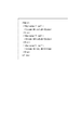
フィルタ入出力管理部303は、フィルタ308と1:1で対応し、フィルタ308と対応する入力ドキュメントストリーム(入力データ保持領域)304、出力ドキュメントストリーム(出力データ保持領域)305、入力チケットストリーム(入力設定領域)306、出力チケットストリーム(出力設定領域)307を管理する。入力ドキュメントストリーム304はフィルタ308が変換しようとするドキュメントファイルを格納し、入力チケットストリーム306はフィルタ308が変換に用いる設定を有するチケットを格納する。一方で、出力ドキュメントストリーム305はフィルタ308が変換したドキュメントファイルを格納し、出力チケットストリーム306はフィルタ308が変換に用いた設定(ログなども含む)を有するチケットを格納する。また、フィルタ入出力管理部303は対応するフィルタ308からの要求に応じて、入力ドキュメントストリーム304や入力チケットストリーム306に保持している内容をフィルタ308に供給する。 次に、本実施形態におけるデータ変換アプリケーションによるジョブの処理について説明する。図18は、データ変換アプリケーション312の各構成を実現するCPU201が、データ変換サービスシステム310からのジョブを処理する手順を示すフローチャートである。ステップS1801で、ジョブに含まれる情報に基づいてフィルタやストリームを構成する(ジョブ初期化と呼称する)。そして、ステップS1802において、ステップ1801構成したフィルタやストリームに沿ってジョブを実行する。
The filter input /
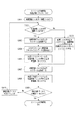
図4は、図18のステップS1801で示したジョブ初期化処理の詳細を表すフローチャートである。なお、図4のフローチャートで示す手順を実行するプログラムはデータ変換サービスサーバ104のRAM202や外部記憶装置204などを含む記憶部のいずれかに記憶され、CPU201により実行される。
FIG. 4 is a flowchart showing details of the job initialization process shown in step S1801 of FIG. A program for executing the procedure shown in the flowchart of FIG. 4 is stored in one of the storage units including the
ステップS401はジョブ管理部301が、データ変換サービスシステム310から設定情報としてのジョブ定義ファイル(以降の説明では単にジョブ定義情報と称する)を受け付ける処理である。ジョブ定義情報は各ジョブの概略を示し、処理内容を示す情報やチケットや処理対象のデータ(ドキュメント)の入出力に関する情報を含む。ジョブ定義情報の詳細については後述する。ジョブ定義情報は各ジョブの先頭に配置してもよいし、ジョブの末尾など所定の位置に配置してもよいし、ジョブに先立って独立してデータ変換サービスシステム310が発行してもよい。
Step S401 is processing in which the
ステップS402はジョブ管理部301が、ステップS401で受け付けたジョブ定義情報から、入力ドキュメントと各種チケットの入力パス情報(入力元を示す情報)を取得する処理である。(ここで、入力パス情報とは、図5において、「InputPath」と「TicketPath」に記述されている情報であり、詳細は後述する。)ジョブ管理部301は取得した入力パス情報の示す記憶領域(プリントサービスサーバ103やデータ変換サービスサーバ104)から入力ドキュメントと各種チケットを取得する。
In step S402, the
ステップS403はジョブ管理部301が、ステップS401で受け付けたジョブ定義情報から、処理後のデータを出力する出力パス情報(出力先を示す情報)を取得する処理である。(ここで、出力パス情報とは、図5において、「OutputPath」に記述されている情報。)
ステップS404はジョブ管理部301が、ステップS401で受け付けたジョブ定義情報から、ジョブの種類を取得する処理である。(ここで、ジョブの種類とは、図5において「Application」に記述されている情報。)
ステップS405はジョブ管理部301が、ステップS404で取得したジョブの種類に基づいてジョブの種類に対応するフィルタの構成情報を取得する処理である。ステップS405の処理の詳細については図6を用いて後述する。
In step S403, the
Step S404 is processing in which the
In step S405, the
ステップS406はジョブ管理部301が、ステップS405で取得したフィルタの構成情報を解析して、フィルタを構成するためのモジュールに関する情報を取得する処理である。ステップS406の処理について図7を用いて詳細は後述する。
In step S406, the
ステップS407はフィルタ制御部302が、入力ドキュメントを引数として、サブルーチンとしての「ストリームの初期化」を呼び出す処理である。サブルーチンとしての「ストリームの初期化」の詳細な説明は図8を用いて後述する。
Step S407 is processing in which the
ステップS408はフィルタ制御部302が、全ての入力チケットに対して、ステップS409の処理を繰り返し行う処理である(S408とS410でループ処理を示す)。
Step S408 is a process in which the
ステップS409はフィルタ制御部302が、入力チケットを引数として、サブルーチンとしての「ストリームの初期化」を呼び出す処理である。サブルーチンとしての「ストリームの初期化」の詳細な説明は図8を用いて後述する。
Step S409 is processing in which the
ステップS410はフィルタ制御部302が、全ての入力チケットに対して、ステップS409の処理を完了した際に「ジョブ初期化」の終了処理に進む処理である。
In step S410, the
<ジョブ定義情報>
図5はジョブ定義情報の一例である。図5に示すジョブ定義情報はXML(Extensible Markup Language)形式で記述されている。ルート要素(ツリー構造で最上位の要素)は「JobDefinition」要素である。また、ジョブ定義情報は、図1に示したプリントシステムで利用可能な複数のプリンタの其々に対応している。
<Job definition information>
FIG. 5 is an example of job definition information. The job definition information shown in FIG. 5 is described in an XML (Extensible Markup Language) format. The root element (the highest element in the tree structure) is a “JobDefinition” element. The job definition information corresponds to each of a plurality of printers that can be used in the print system shown in FIG.
「JobDefinition」要素の子要素には、「Application」要素、「InputPath」要素、「OutputPath」要素、「TicketPath」要素がある。「TicketPath」要素は入力チケットの数だけ存在する。「Application」要素には、データ変換サービスシステム310がデータ変換アプリケーションを利用して実現する機能に関する情報が記述されている。「Application」要素の「id」属性には当該機能の名前が記述されている。
Child elements of the “JobDefinition” element include an “Application” element, an “InputPath” element, an “OutputPath” element, and a “TicketPath” element. There are as many “TicketPath” elements as the number of input tickets. In the “Application” element, information on a function realized by the data
「InputPath」要素には、入力ドキュメントの情報が記述されている。「InputPath」要素の「value」属性には入力ドキュメントのパスが記述されている。「OutputPath」要素には、処理後のデータの出力に関する情報が記述されている。「OutputPath」要素の「value」属性には処理後のデータを出力するパスが記述されている。「TicketPath」要素には、入力チケットの情報が記述されている。「TicketPath」要素の「type」属性には入力チケットの種類を示す識別子が記述されている。「TicketPath」要素の「value」属性には入力チケットのパスが記述されている。 Information on the input document is described in the “InputPath” element. The “value” attribute of the “InputPath” element describes the path of the input document. In the “OutputPath” element, information related to output of processed data is described. In the “value” attribute of the “OutputPath” element, a path for outputting the processed data is described. In the “TicketPath” element, information of the input ticket is described. An identifier indicating the type of the input ticket is described in the “type” attribute of the “TicketPath” element. The “value” attribute of the “TicketPath” element describes the path of the input ticket.
<対応情報>
図6は、ジョブの種類とフィルタの構成情報との対応関係を示す対応情報の一例である。対応情報は構成保持部309に格納されている。図6に示す対応情報はXML形式で記述されている。ルート要素は「Applications」要素である。「Applications」要素の子要素には、「Application」要素がある。「Application」要素には、ジョブの種類(「id」属性)と、ジョブの種類に対応するフィルタの構成情報(「FilterConfig」要素の「path」属性)が記述されている。
<Correspondence information>
FIG. 6 is an example of correspondence information indicating the correspondence between job types and filter configuration information. The correspondence information is stored in the
図5のステップS405では、ジョブ管理部301が、ステップS404で取得したジョブの種類に基づいて、図6の対応情報の「Application」要素について「id」属性を検索する。一致したら、ジョブ管理部301が、「Application」要素の子要素である「FilterConfig」要素の「path」属性から、フィルタの構成情報を取得する。図6の例において、ジョブ管理部301はステップS404で取得した“PrintService1”に基づいて、対応情報の「Application」要素の「id」属性(601)を検索する。その後、ジョブ管理部301が「Application」要素の子要素である「FilterConfig」要素の「path」属性から、ジョブを処理するためのフィルタ構成情報の記憶領域を示す情報として、“.¥PrintService1_FilterConfig.xml”を取得する。
In step S405 in FIG. 5, the
<フィルタ構成情報>
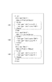
図7はフィルタの接続順を規定するフィルタ構成情報(以下、単に構成情報と称す)の一例である。フィルタ構成情報は構成保持部309に複数保持されている。図7に示す構成情報はXML形式で記述されている例である。ルート要素である「Filters」要素の子要素として、「Filter」要素が複数記載されている。「Filters」要素の子要素には、「Module」要素が存在する。「Module」要素にはフィルタのモジュールのパス(ここでは、フィルタの各モジュールの記憶領域を示す情報)が記載されている。ステップS406では、ジョブ管理部301が、「Filter」要素の記載順にFilterの順序構成を取得する。図7の例では、FilterA、FilterB、FiltreCの順番で記述されており、この順番がジョブの処理順序に相当する。
<Filter configuration information>
FIG. 7 is an example of filter configuration information (hereinafter simply referred to as configuration information) that defines the connection order of filters. A plurality of pieces of filter configuration information are held in the
ここで、ステップS404からステップS406において、ジョブ定義情報に記載されているジョブの種類を基に、構成保持部309からフィルタ構成情報を取得して、フィルタ構成を決定する手法を示した。但し、本発明ではこの手法に限定されるものではなく、ジョブ定義情報にフィルタ構成情報に関する情報を含め、フィルタ構成情報に基づき、フィルタ構成を決定してもよい。
Here, the method of acquiring the filter configuration information from the
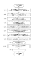
図8は、図4のステップS407やS409に示したストリームの初期化処理の詳細を表すフローチャートである。各ステップは図4と同様に、CPU201によって実行される。なお、ストリームの初期化によって、図3に示す各ストリーム(入力ドキュメントストリーム304、出力ドキュメントストリーム305、入力チケットストリーム306、出力チケットストリーム307)を初期化(又は生成)することができる。
FIG. 8 is a flowchart showing details of the stream initialization process shown in steps S407 and S409 of FIG. Each step is executed by the
ステップS801はフィルタ制御部302が、処理対象フィルタ(ストリームの初期化処理の対象となるフィルタ)を、初段フィルタとして設定する処理である。
Step S801 is processing in which the
ステップS802は、処理対象フィルタが初段フィルタか否かをフィルタ制御部302が判断する処理である。処理対象フィルタが初段フィルタである場合にはステップS803に進む。処理対象フィルタが初段フィルタではない場合にはステップS806に進む。
Step S802 is processing in which the
ステップS803はフィルタ制御部302が、処理対象ファイルの入力ストリームを作成する処理である。
Step S803 is processing in which the
ステップS804はフィルタ制御部302が、ステップS402で取得した処理対象ファイルの入力データを、ステップS803で作成した入力ストリームに書き込む処理である。
In step S804, the
ステップS805はフィルタ制御部302が、ステップS803で作成した入力ストリームを、処理対象フィルタ用のフィルタ入出力管理部303にセットする処理である。
In step S805, the
ステップS806はフィルタ制御部302が、処理対象フィルタの前段フィルタの処理において、ステップS807で作成した出力ストリームを、現在の処理対象フィルタのフィルタ入出力管理部303に入力ストリームをしてセットする処理である。本ステップの処理によって、処理対象フィルタの前段フィルタの出力ストリームと、処理対象フィルタの入力ストリームは同じストリームとなる。
Step S806 is a process in which the
ステップS807はフィルタ制御部302が、処理対象ファイルの出力ストリームを作成する処理である。その後、出力ストリームを前回作成時の出力ストリームをして保存する。
Step S807 is processing in which the
ステップS808はフィルタ制御部302が、ステップS807で作成した出力ストリームを、処理対象フィルタ用のフィルタ入出力管理部303にセットする処理である。
In step S808, the
ステップS809は、処理対象フィルタが最終フィルタか否かをフィルタ制御部302が判断する処理である。最終フィルタである場合は終了処理に進む。最終フィルタでない場合はステップS810に進む。
Step S809 is processing in which the
ステップS810はフィルタ制御部302が、処理対象フィルタを、現在の処理対象フィルタの次のフィルタと設定する処理である。
Step S810 is processing in which the
ステップS801、ステップS809、及びステップS810の処理によって、初段フィルタから最終フィルタまでの全てのフィルタに対して、ステップS802からステップS808の処理を実行する。 Through the processes of Step S801, Step S809, and Step S810, the processes of Step S802 to Step S808 are executed for all the filters from the first stage filter to the final filter.
このようにして、複数のフィルタの間の接続を制御する。上述の処理は、フィルタの1つを着目フィルタ(着目処理部)とすると、着目フィルタの次に処理をするフィルタの入力ストリーム(入力ドキュメントストリーム304、入力チケットストリーム306)として着目フィルタに対応する出力ストリーム(出力ドキュメントストリーム305、出力チケットストリーム307)を割り当てることに相当する。
In this way, the connection between the plurality of filters is controlled. In the above processing, if one of the filters is a target filter (target processing unit), an output corresponding to the target filter is input as an input stream (
次に図9を用いて、図18のステップS1802で示した、データ変換アプリケーションにおけるジョブ実行処理の詳細について説明する。なお、ジョブ実行処理は、ジョブ初期化処理が完了した後に開始する。 Next, details of job execution processing in the data conversion application shown in step S1802 in FIG. 18 will be described with reference to FIG. Note that the job execution process starts after the job initialization process is completed.
なお、図9のフローチャートで示す手順はデータ変換サービスサーバ104のRAM202、もしくは外部記憶装置204のいずれかの記憶手段に記憶され、CPU201により実行される。
The procedure shown in the flowchart of FIG. 9 is stored in either the
ステップS901はフィルタ制御部302が、全てのフィルタ308に対してステップS902の処理を実行する処理である。
Step S901 is a process in which the
ステップS902はフィルタ制御部302が、フィルタ308に対して初期化を指示する処理である。
Step S902 is processing in which the
ステップS903はフィルタ制御部302が、全てのフィルタ308に対して、ステップS902の処理を完了した際にステップS904に進む処理である。
Step S903 is processing that proceeds to step S904 when the
ステップS904はフィルタ制御部302、及びフィルタ入出力管理部303が、全てのフィルタ308に対してステップS905からステップS907の処理を実行する処理である。なお、ステップS905からステップS907の処理はフィルタ毎に並列に実行する。
Step S904 is processing in which the
ステップS905はフィルタ制御部302が、フィルタ308に対して処理実行を指示する処理である。フィルタ308では処理実行の指示にしたがい処理を進める。
Step S905 is processing in which the
ステップS906はフィルタ入出力管理部303が、処理実行中のフィルタ308から各種入力、及び出力ストリームの提供要求を受け付け、フィルタ308にストリームを提供する処理である。ここで、ストリームにデータが書き込まれている場合は、フィルタ入出力管理部303はストリームをすぐにフィルタ308に提供する。ストリームにデータが書き込まれていない場合は、フィルタ入出力管理部303がストリームにデータが書き込まれるまで待ってから、ストリームをフィルタ308に提供する。フィルタ308では、提供された入力ストリームからデータを読み込み、データ変換処理を実行後、出力ストリームに変換後のデータを出力する。
In step S <b> 906, the filter input /
ステップS907はフィルタ制御部302が、フィルタ308から処理が完了して、出力ストリームにデータを書き込んだことの通知を受け取る処理である。
Step S907 is processing in which the
ステップS908はフィルタ制御部302、及びフィルタ入出力管理部303が、全てのフィルタ308に対して、ステップS905からステップS907の処理を完了した際にステップS909に進む処理である。
Step S908 is processing that proceeds to step S909 when the
ステップS909はフィルタ制御部302が、最終フィルタの出力ドキュメントストリームに書き込まれたデータ、即ちデータ変換アプリケーションの出力となるデータを、ステップS403で取得した出力パスに従って出力する処理である。
In step S909, the
ステップS910はジョブ管理部301が、フィルタ308の処理結果をデータ変換サービスシステム310に通知する処理である。
In step S910, the
以上説明したように、本実施形態によればジョブ定義情報に基づいてデータ変換処理やデータ処理、入出力処理を組み立てるので、各種プリンタに対応した複数のプリンタドライバをサーバに用意する必要がなくなる。また、データ変換処理の共通部分を重複して保持することを少なくでき、サーバの保守の利便性を向上させたり、サーバの記憶容量を削減したりできる。 As described above, according to the present embodiment, since data conversion processing, data processing, and input / output processing are assembled based on job definition information, it is not necessary to prepare a plurality of printer drivers corresponding to various printers in the server. In addition, it is possible to reduce the duplication of common parts of the data conversion process, thereby improving the convenience of server maintenance and reducing the storage capacity of the server.
<実施形態2>
実施形態1では全てのフィルタに対して、入力ドキュメントと全ての入力チケットのストリームを作成した。しかし、実際には、特定の入力チケットを必要としないフィルタも存在する。例えば、テキストデータをPDFに変換するフィルタの場合には、印刷設定が記述されているチケット(以降、プリントチケットと表記する)は必要がない。実施形態1では、このようなフィルタが存在する場合であっても、全てのフィルタに対してプリントチケットのストリームを作成する。そのため、プリントチケットを必要としないフィルタであっても、プリントチケットを出力ストリームに出力する処理を余分に行うこととなってしまう。そこで実施形態2では、入力チケットに対して読み書きを行わないフィルタとして判定された場合には、そのフィルタを飛ばして、チケットを利用するフィルタのみストリームを作成して接続する。なお、実施形態2の説明では、実施形態1と同一機能を有する構成や工程には同一符号を付すとともに、構成的、機能的にかわらないものについてはその説明を省略する。
<Embodiment 2>
In the first embodiment, an input document and a stream of all input tickets are created for all filters. However, there are actually filters that do not require a specific input ticket. For example, in the case of a filter that converts text data into PDF, there is no need for a ticket in which print settings are described (hereinafter referred to as a print ticket). In the first embodiment, even if such a filter exists, a print ticket stream is created for all the filters. Therefore, even if the filter does not require a print ticket, an extra process for outputting the print ticket to the output stream is performed. Therefore, in the second embodiment, when it is determined as a filter that does not read / write the input ticket, the filter is skipped, and only a filter that uses the ticket is created and connected. In the description of the second embodiment, configurations and processes having the same functions as those of the first embodiment are denoted by the same reference numerals, and descriptions of those that are not structurally and functionally omitted are omitted.
図10は実施形態2における、ジョブ初期化処理の詳細を表すフローチャートである。図4からの変更点はステップS1001、ステップS1002が追加されており、ステップS409の代わりにステップS1002が使用されていることである。なお、図10のフローチャートで示す手順はデータ変換サービスサーバ104のRAM202、もしくは外部記憶装置204のいずれかの記憶部に記憶され、CPU201により実行される。
FIG. 10 is a flowchart showing details of job initialization processing in the second embodiment. The change from FIG. 4 is that step S1001 and step S1002 are added, and step S1002 is used instead of step S409. The procedure shown in the flowchart of FIG. 10 is stored in either the
ステップS1001はジョブ管理部301が、ステップS405で取得したフィルタの構成情報を解析して、各フィルタが利用するチケット情報を取得する処理である。ステップS1001の処理について図11を用いて説明する。
In step S1001, the
図11は実施形態2におけるフィルタの構成情報の一例である。図7に示したフィルタの構成情報との違いは、「Filter」要素の子要素として「Tickets」要素(1101、1102、1103)が追加されていることである。「Tickets」要素には使用するチケットの情報が、子要素である「Ticket」要素に記載されている。「Ticket」要素の「type」属性にはチケットの種類が記載されている。ステップS1001では、ジョブ管理部301が、「Tickets」要素を読み込んで、子要素である「Ticket」要素の情報を、利用するチケットの情報として取得する。図11の例において、まず「name」属性が“FilterA”の「Filter」要素の子要素である「Tickets」要素を読み込む。「Tickets」要素には、「type」属性が“Ticket1”の「Ticket」要素と、「type」属性が“Ticket2”の「Ticket」要素が子要素として存在する(1101)。そのため、FilterAがTicket1とTicket2を使用することを取得することが出来る。次に、「name」属性が“FilterB”の「Filter」要素の子要素である「Tickets」要素を読み込む。「Tickets」要素には、「type」属性が“Ticket2”の「Ticket」要素が子要素として存在する(1102)。そのため、FilterBがTicket2を使用することを取得出来る。更に、「name」属性が“FilterC”の「Filter」要素の子要素である「Tickets」要素を読み込む。「Tickets」要素には、「type」属性が“Ticket1”の「Ticket」要素が子要素として存在する(1103)。そのため、FilterCがTicket1を使用することを取得出来る。
FIG. 11 is an example of filter configuration information according to the second embodiment. The difference from the filter configuration information shown in FIG. 7 is that “Tickets” elements (1101, 1102, 1103) are added as child elements of the “Filter” element. In the “Tickets” element, information of a ticket to be used is described in a “Ticket” element that is a child element. The ticket type is described in the “type” attribute of the “Ticket” element. In step S <b> 1001, the
図10に戻り、ステップS1002はフィルタ制御部302が、入力チケットを引数として、サブルーチン「チケットストリームの初期化」を呼び出す処理である。サブルーチン「チケットストリームの初期化」の詳細説明は図12を用いて後述する。
Returning to FIG. 10, step S <b> 1002 is processing in which the
図12は実施形態2における、チケットストリームを初期化するサブルーチンの処理を表すフローチャートである。実施形態1において同様の処理を行っていた図4からの変更点は、ステップS1201からステップS1205が追加されており、ステップS1203がステップS802の代わり、ステップS1205がステップS806の代わりに使用されることである。 FIG. 12 is a flowchart showing processing of a subroutine for initializing a ticket stream in the second embodiment. A change from FIG. 4 in which the same processing is performed in the first embodiment is that step S1201 to step S1205 are added, step S1203 is used instead of step S802, and step S1205 is used instead of step S806. It is.
ステップS1201はフィルタ制御部302が、入力ストリーム作成済フラグをOFFと設定する処理である。入力ストリーム作成済フラグはステップS1203、ステップS1204で使用される。
Step S1201 is processing in which the
ステップS1202は、処理対象フィルタが処理対象ファイルを利用するか否かをフィルタ制御部302が判断する処理である。なお、処理対象フィルタが処理対象ファイルを利用するか否かの情報は、ステップS1001で取得した情報である。処理対象フィルタが、処理対象ファイルを利用する場合はステップS1203に進む。処理対象フィルタが、処理対象ファイルを利用しないと判定した場合はステップS809に進む。
Step S1202 is processing in which the
ステップS1203はフィルタ制御部302が、入力ストリーム作成済フラグを確認する処理である。入力ストリーム作成済フラグがOFFの場合はステップS803に進む。入力ストリーム作成済フラグがONの場合はステップS1205に進む。このフラグを設けることにより、最初にチケットを使うフィルタだけステップS803〜S1204の処理により入力ストリームが作成される。以降のフィルタはステップS1205の処理により、前回作成時の出力ストリームが、処理対象フィルタの入力ストリームとしてセットされる
ステップS1204はフィルタ制御部302が、入力ストリーム作成済フラグをONと設定する処理である。ステップS1201,S1203、S1204の処理により、入力ストリームを作成する処理(ステップS803からS805)は最初の一回のみ実行される。
Step S1203 is processing in which the
ステップS1205はフィルタ制御部302が、ステップS807で保存した前回作成時の出力ストリームを、現在の処理対象フィルタのフィルタ入出力管理部303に入力ストリームをしてセットする処理である。本ステップの処理によって、前回作成時の出力ストリームと、処理対象フィルタの入力ストリームは同じストリームとなる。
In step S1205, the
以上の本実施形態によれば、各フィルタは自身で参照する必要がないチケットについての読み書き処理をスキップするため、実施形態1に比べて処理を高速に実行することができる。 According to the present embodiment described above, each filter skips the read / write process for a ticket that does not need to be referred to by itself, so that the processing can be executed at a higher speed than in the first embodiment.
<実施形態3>
実施形態1では前段フィルタがチケットを書き込むまで、次段フィルタはチケットを読む事が出来ない。前段フィルタの処理の完了を待つ必要があるため、各フィルタは並列に処理が出来ない。実施形態3では、チケットを次に書き込むフィルタまで自動的にコピーする手法を示す。なお、実施形態3の説明では、実施形態1、2と同一機能を有する構成や工程には同一符号を付すとともに、構成的、機能的にかわらないものについてはその説明を省略する。
<Embodiment 3>
In the first embodiment, the next-stage filter cannot read the ticket until the previous-stage filter writes the ticket. Since it is necessary to wait for the completion of the processing of the pre-filter, the filters cannot be processed in parallel. In the third embodiment, a method of automatically copying a ticket up to a filter to be written next is shown. In the description of the third embodiment, configurations and processes having the same functions as those in the first and second embodiments are denoted by the same reference numerals, and descriptions of those that are not structurally and functionally omitted are omitted.
図13は実施形態3における、ジョブ初期化処理を表すフローチャートである。図4からの変更点はステップS1301、ステップS1302が追加されていることである。なお、図13のフローチャートで示す手順はデータ変換サービスサーバ104のRAM202、もしくは外部記憶装置204のいずれかの記憶手段に記憶され、CPU201により実行される。
FIG. 13 is a flowchart showing job initialization processing in the third embodiment. The change from FIG. 4 is that step S1301 and step S1302 are added. The procedure shown in the flowchart of FIG. 13 is stored in either the
ステップS1301はジョブ管理部301が、ステップS405で取得したフィルタの構成情報を解析して、各フィルタが利用するチケットのアクセス権情報(処理属性)を取得する処理である。ステップS1301の処理について図14を用いて説明する。
In step S1301, the
図14は実施形態3におけるフィルタの構成情報の一例である。図7に示したフィルタの構成情報との違いは、「Filter」要素の子要素として「Tickets」要素(1401、1402、1403)が追加されていることである。「Tickets」要素には使用するチケットの情報が、子要素である「Ticket」要素に記載されている。「Ticket」要素の「type」属性にはチケットの種類が記載されている。「Ticket」要素の「access」属性にはチケットのアクセス情報が記載されている。「access」属性には、チケットを読み込む場合には”R”、チケットを書き込む場合は”W”を記述する。ステップS1301では、「Tickets」要素の子要素である「Ticket」要素を読み込んで、「type」属性と「access」属性の情報を取得する。図14の例において、まず「name」属性が“FilterA”の「Filter」要素の子要素である「Tickets」要素を読み込む。「Tickets」要素には、子要素として2つの「Ticket」要素が存在する。1つは、「type」属性が“Ticket1”、「access」属性が“R”の「Ticket」要素であり、もう1つは「type」属性が“Ticket2”、「access」属性が“RW”の「Ticket」要素である(1401)。そのため、FilterAがTicket1に対して読み込みのみを行い、Ticket2に対して読み込みと書き込みを行うことを取得出来る。次に、「name」属性が“FilterB”の「Filter」要素の子要素である「Tickets」要素を読み込む。「Tickets」要素には、子要素として2つの「Ticket」要素が存在する。1つは、「type」属性が“Ticket1”、「access」属性が“RW”の「Ticket」要素であり、もう1つは「type」属性が“Ticket2”、「access」属性が“R”の「Ticket」要素である(1402)。そのため、FilterBがTicket1に対して読み込みと書き込みを行い、Ticket2に対して読み込みのみを行うことを取得出来る。更に、「name」属性が“FilterC”の「Filter」要素の子要素である「Tickets」要素を読み込む。「Tickets」要素には、子要素として2つの「Ticket」要素が存在する。1つは「type」属性が“Ticket1”、「access」属性が“R”の「Ticket」要素であり、もう1つは「type」属性が“Ticket2”、「access」属性が“R”の「Ticket」要素である(1403)。そのため、FilterCがTicket1に対して読み込みのみを行い、Ticket2に対して読み込みのみを行うことを取得出来る。
FIG. 14 is an example of filter configuration information according to the third embodiment. The difference from the filter configuration information shown in FIG. 7 is that “Tickets” elements (1401, 1402, 1403) are added as child elements of the “Filter” element. In the “Tickets” element, information of a ticket to be used is described in a “Ticket” element that is a child element. The ticket type is described in the “type” attribute of the “Ticket” element. In the “access” attribute of the “Ticket” element, ticket access information is described. In the “access” attribute, “R” is described when a ticket is read, and “W” is described when a ticket is written. In step S1301, the “Ticket” element that is a child element of the “Tickets” element is read, and information on the “type” attribute and the “access” attribute is acquired. In the example of FIG. 14, first, a “Tickets” element that is a child element of the “Filter” element whose “name” attribute is “FilterA” is read. In the “Tickets” element, there are two “Ticket” elements as child elements. One is a “Ticket” element having a “type” attribute of “Ticket1” and an “access” attribute of “R”, and the other is a “type” attribute of “Ticket2” and an “access” attribute of “RW”. "Ticket" element (1401). Therefore, it can be acquired that Filter A performs only reading with respect to
図13に戻り、ステップS1302はフィルタ制御部302が、初段フィルタと入力チケットを引数として、サブルーチン「チケットの自動コピー」を呼び出す処理である。サブルーチン「チケットの自動コピー」の詳細説明は図16を用いて後述する。
Returning to FIG. 13, step S1302 is a process in which the
図15は実施形態3における、ジョブの実行処理を表すフローチャートである。実施形態1において同様の処理を行っていた図9のフローチャートの代わりに使用される。図4からの変更点はステップS1501からS1503が追加されていることである。なお、図15のフローチャートで示す手順はデータ変換サービスサーバ104のRAM202、もしくは外部記憶装置204のいずれかの記憶手段に記憶され、CPU201により実行される。
FIG. 15 is a flowchart illustrating job execution processing according to the third embodiment. It is used instead of the flowchart of FIG. 9 in which the same processing is performed in the first embodiment. The change from FIG. 4 is that steps S1501 to S1503 are added. The procedure shown in the flowchart of FIG. 15 is stored in either the
ステップS1501はフィルタ制御部302が、全ての入力チケットに対して、ステップS1502の処理を繰り返し行う処理である。ここで入力チケットとは、ジョブ初期化時においてステップS402で取得したものである。
Step S1501 is a process in which the
ステップS1502はフィルタ制御部302が、フィルタと入力チケットを引数として、サブルーチン「チケットの自動コピー」を呼び出す処理である。サブルーチン「チケットの自動コピー」の詳細説明は図16を用いて後述する。本ステップの処理により、次段フィルタ以降の入力チケットの入力ストリームにデータが書きこまれる。その結果、次段フィルタ以降のステップS906の処理において、フィルタに入力チケットの入力ストリームを提供することが可能となり、次段以降のフィルタでは入力チケットに関する処理を進めることが可能となる。
Step S1502 is a process in which the
ステップS410はフィルタ制御部302が、全ての入力チケットに対して、ステップS1502の処理を完了した際にステップS907に進む処理である。
Step S410 is a process that proceeds to step S907 when the
図16は本実施3における、チケットの自動コピーを行うサブルーチンの処理を表すフローチャートである。 FIG. 16 is a flowchart showing processing of a subroutine for performing automatic ticket copying in the third embodiment.
ステップS1601はフィルタ制御部302が、ステップS406で取得したフィルタの構成に基づき、コピー元フィルタが最終フィルタか否かを判断する処理である。最終フィルタである場合には終了処理に進む。最終フィルタでない場合にはステップS1602に進む。
Step S1601 is processing in which the
ステップS1602はフィルタ制御部302が、コピー先フィルタをコピー元フィルタの次段フィルタと設定する処理である。コピー元フィルタの次段フィルタは、ステップS406で取得したフィルタの構成から決定する。
In step S1602, the
ステップS1603は、コピー元のフィルタが処理対象チケットを書き込むか否かをフィルタ制御部302が判断する処理である。コピー元のフィルタが処理対象チケットを書き込むか否かの情報はステップS1301で取得したものである。コピー元のフィルタが処理対象チケットを書き込む場合は終了処理に進む。コピー元のフィルタが処理対象チケットを書き込まない場合はステップS1604に進む
ステップS1604はフィルタ制御部302が、コピー元フィルタの処理対象チケットの入力ストリームの内容を、コピー先フィルタの処理対象チケットの入力ストリームにコピーする処理である。
In step S1603, the
ステップS1605はフィルタ制御部302が、コピー元フィルタを現在のコピー先フィルタと設定する処理である。その後、ステップS1601に進み、本ステップで設定したコピー元フィルタについて同様にステップS1601からステップS1604の処理を実行する。
In step S1605, the
次に図16のフローに従ってチケットの自動コピーがどのように行われるか、図17を用いて説明する。 Next, how the ticket is automatically copied according to the flow of FIG. 16 will be described with reference to FIG.
図17(a)は図13に示すジョブ初期化処理のフローにおいて、チケットの自動コピーを行った場合(ステップS1302)のデータ変換アプリケーションの概念図である。なおステップS1302において、引数の入力チケットはTicket1であるものとする。図17(a)の例では、フィルタ構成は、フィルタA1701、フィルタB1702、フィルタC1703の順にフィルタが構成されている。また、処理対象チケットであるTicket1のアクセス情報は、フィルタA1701は「読み込みのみ(リードオンリー)」、フィルタB1702は「読み込みと書き込み」、フィルタC1703は「読み込みのみ」となっている。 FIG. 17A is a conceptual diagram of a data conversion application when a ticket is automatically copied (step S1302) in the job initialization process flow shown in FIG. In step S1302, it is assumed that the argument input ticket is Ticket1. In the example of FIG. 17A, the filters are configured in the order of filter A1701, filter B1702, and filter C1703. In addition, the access information of Ticket1, which is the processing target ticket, is “read only (read only)” for filter A1701, “read and write” for filter B1702, and “read only” for filter C1703.
ステップS1601では、コピー元フィルタであるフィルタA1701は最終フィルタではないため、ステップS1602に進む。ステップS1602では、コピー先フィルタは、フィルタA1701の次段フィルタであるフィルタB1702と設定される。ステップS1603では、コピー元フィルタであるフィルタA1701は、処理対象チケットであるTicket1を書き込まないため、ステップS1604に進む。ステップS1604では、フィルタA1701のTicket1の入力用ストリーム1704の内容が、フィルタB1702のTicket1の入力用ストリーム1705にコピーされる。ステップS1605では、コピー元フィルタはフィルタA1701の次段であるフィルタB1702と設定される。
In step S1601, since the filter A1701 that is the copy source filter is not the final filter, the process advances to step S1602. In step S1602, the copy destination filter is set as the filter B1702 which is the next stage filter of the filter A1701. In step S1603, the filter A1701 that is the copy source filter does not write Ticket1 that is the processing target ticket, and thus the process proceeds to step S1604. In
再びステップS1601では、フィルタBは最終段フィルタではないため、ステップS1602に進む。ステップS1602では、コピー先フィルタは、フィルタB1702の次段フィルタであるフィルタC1703と設定される。ステップS1603では、フィルタB1702は処理対象チケットであるTicket1を書き込むと判断する。そのため、フィルタB1702のTicket1の入力用ストリーム1705の内容が、フィルタC1703のTicket1の入力用ストリーム1706にコピーされず、チケットの自動コピー処理を終了する。
In step S1601 again, since the filter B is not the final stage filter, the process proceeds to step S1602. In step S1602, the copy destination filter is set as the filter C1703, which is the next stage filter of the filter B1702. In step S1603, the
図17(b)は図15に示すジョブ実行処理のフローにおいて、チケットの自動コピーを行った場合(ステップS1502)のデータ変換アプリケーションの概念図である。なおステップS1502において、引数のフィルタはフィルタB1702、入力チケットはTicket2であるものとする。図17(b)の例では、フィルタ構成は、フィルタA1701、フィルタB1702、フィルタC1703の順にフィルタが構成されている。また、処理対象チケットであるTicket2のアクセス情報は、フィルタA1701は「読み込みと書き込み」、フィルタB1702は「読み込みのみ」、フィルタC1703は「読み込みのみ」となっている。
FIG. 17B is a conceptual diagram of the data conversion application when a ticket is automatically copied (step S1502) in the flow of job execution processing shown in FIG. In step S1502, it is assumed that the argument filter is filter B1702 and the input ticket is Ticket2. In the example of FIG. 17B, the filters are configured in the order of filter A1701, filter B1702, and filter C1703. Also, the access information of Ticket 2 as the processing target ticket is “read and write” for the
ステップS1601では、コピー元フィルタであるフィルタB1702は最終フィルタではないため、ステップS1602に進む。ステップS1602では、コピー先フィルタは、フィルタB1702の次段フィルタであるフィルタC1703と設定される。ステップS1603では、コピー元フィルタであるフィルタB1702は、処理対象チケットであるTicket2を書き込まないため、ステップS1604に進む。ステップS1604では、フィルタB1702のTicket2の入力用ストリーム1708の内容が、フィルタC1703のTicket2の入力用ストリーム1709にコピーされる。ステップS1605では、コピー元フィルタはフィルタB1702の次段であるフィルタC1703と設定される。
In step S1601, since the
再びステップS1601では、フィルタCは最終段フィルタであるため、コピー先のフィルタが存在しない、そのため、チケットの自動コピー処理を終了する。 In step S1601 again, since the filter C is the final stage filter, there is no copy destination filter. Therefore, the automatic ticket copying process is terminated.
以上、本実施形態によれば、読み込みのみ(リードオンリー)のチケットについては、処理を開始する際に複数のフィルタのチケット作業領域(入力チケットストリーム)にコピーされ、複数のフィルタで並列にチケットの処理が可能となる。従って、各フィルタによる処理の並列実効性を高めることができる。 As described above, according to the present embodiment, a read-only (read-only) ticket is copied to a ticket work area (input ticket stream) of a plurality of filters when processing is started, and the tickets are parallelized by a plurality of filters. Processing is possible. Therefore, the parallel effectiveness of processing by each filter can be enhanced.
上述の実施形態ではプリントシステムについて説明したが、本発明はプリントシステムに限られない。例えば、閲覧デバイス用のデータに変換するデータ変換システムにおいても本発明を適用することで、各デバイス用に個別にプログラムを用意しなくて済む。 Although the printing system has been described in the above embodiment, the present invention is not limited to the printing system. For example, by applying the present invention to a data conversion system that converts data for browsing devices, it is not necessary to prepare a program for each device individually.
また、本発明は、以下の処理を実行することによっても実現される。即ち、上述した実施形態の機能を実現するソフトウェア(プログラム)を、ネットワーク又は各種記憶媒体を介してシステム或いは装置に供給し、そのシステム或いは装置のコンピュータ(またはCPUやMPU等)が、コンピュータ読み取り可能なプログラムを読み出して実行する処理である。 The present invention can also be realized by executing the following processing. That is, software (program) that realizes the functions of the above-described embodiments is supplied to a system or apparatus via a network or various storage media, and a computer (or CPU, MPU, etc.) of the system or apparatus can be read by a computer. This process reads out and executes a simple program.
Claims (11)
前記ジョブを処理するための複数の処理手段と、
前記複数の処理手段の間の接続を規定する構成情報を複数保持する保持手段と、
処理対象のジョブを受信し、当該ジョブに含まれる設定情報に基づいて、当該ジョブを処理するための構成情報を前記保持手段から取得する受信手段と、
前記受信手段が取得した構成情報に基づいて、前記複数の処理手段の間の接続を設定する接続手段とを有し、
前記接続手段は、前記複数の処理手段ごとに、各処理手段に入力する入力データを処理するための設定情報を保持する入力設定領域と、各処理手段で処理した出力データに関する設定情報を保持する出力設定領域と、をメモリに割り当て、着目処理手段の出力設定領域を、当該着目処理手段の出力データを処理する第1処理手段の入力設定領域として割り当てる際に、当該第1処理手段が前記設定情報を参照しない場合に、前記着目処理手段の出力設定領域を、前記第1処理手段の出力データを処理する第2処理手段の入力設定領域として割り当てる
ことを特徴とするデータ処理装置。 A data processing apparatus for processing a job including data and setting information for processing the data,
A plurality of processing means for processing the job;
Holding means for holding a plurality of pieces of configuration information defining connections between the plurality of processing means;
A receiving unit that receives a job to be processed and acquires configuration information for processing the job from the holding unit based on setting information included in the job;
Connection means for setting connections between the plurality of processing means based on the configuration information acquired by the receiving means ;
The connection means holds, for each of the plurality of processing means, an input setting area for holding setting information for processing input data input to each processing means, and setting information relating to output data processed by each processing means. When the output setting area is assigned to the memory, and the output setting area of the target processing means is assigned as the input setting area of the first processing means for processing the output data of the target processing means, the first processing means The data processing apparatus characterized by allocating the output setting area of the target processing means as the input setting area of the second processing means for processing the output data of the first processing means when information is not referred to .
に基づいてPDF形式に変換することを特徴とする請求項1乃至6のいずれか1項に記載
のデータ処理装置。 7. The data processing apparatus according to claim 1, wherein at least one of the plurality of processing units converts data included in the job into a PDF format based on the setting information. .
前記データ変換サービスサーバが、
前記ジョブを処理するための複数の処理手段と、
前記複数の処理手段の間の接続を規定する構成情報を複数保持する保持手段と、
処理対象のジョブを受信し、当該ジョブに含まれる設定情報が示す種類に基づいて、当該ジョブを処理するための構成情報を前記保持手段から取得する受信手段と、
前記受信手段が取得した構成情報に基づいて、前記複数の処理手段の間の接続を設定する接続手段とを備え、
前記接続手段は、前記複数の処理手段ごとに、各処理手段に入力する入力データを処理するための設定情報を保持する入力設定領域と、各処理手段で処理した出力データに関する設定情報を保持する出力設定領域と、をメモリに割り当て、着目処理手段の出力設定領域を、当該着目処理手段の出力データを処理する第1処理手段の入力設定領域として割り当てる際に、当該第1処理手段が前記設定情報を参照しない場合に、前記着目処理手段の出力設定領域を、前記第1処理手段の出力データを処理する第2処理手段の入力設定領域として割り当てることを特徴とするプリントシステム。 A client that transmits a job as a print instruction, a printer that performs printing based on the print instruction, a print service server that issues a data conversion request based on the job transmitted by the client, and a data conversion request based on the data conversion request A data conversion service server for converting the job into print data suitable for the printer,
The data conversion service server is
A plurality of processing means for processing the job;
Holding means for holding a plurality of pieces of configuration information defining connections between the plurality of processing means;
A receiving unit that receives a job to be processed and acquires configuration information for processing the job from the holding unit based on a type indicated by setting information included in the job;
Connection means for setting connections between the plurality of processing means based on the configuration information acquired by the receiving means,
The connection means holds, for each of the plurality of processing means, an input setting area for holding setting information for processing input data input to each processing means, and setting information relating to output data processed by each processing means. When the output setting area is assigned to the memory, and the output setting area of the target processing means is assigned as the input setting area of the first processing means for processing the output data of the target processing means, the first processing means If you do not see the information, print system wherein the output setting region of interest processing means and assign as input setting area of the second processing means for processing the output data of the first processing means.
処理対象のジョブを受信し、当該ジョブに含まれる設定情報が示す種類に基づいて、当該ジョブを処理するための構成情報を前記保持手段から取得する受信工程と、
前記受信工程で取得した構成情報に基づいて、前記複数の処理手段の間の接続を設定する接続工程とを有し、
前記接続工程では、前記複数の処理手段ごとに、各処理手段に入力する入力データを処理するための設定情報を保持する入力設定領域と、各処理手段で処理した出力データに関する設定情報を保持する出力設定領域と、をメモリに割り当て、着目処理手段の出力設定領域を、当該着目処理手段の出力データを処理する第1処理手段の入力設定領域として割り当てる際に、当該第1処理手段が前記設定情報を参照しない場合に、前記着目処理手段の出力設定領域を、前記第1処理手段の出力データを処理する第2処理手段の入力設定領域として割り当てることを特徴とするデータ処理装置の制御方法。 Data comprising a plurality of processing means for processing a job including data and setting information for processing the data, and holding means for holding a plurality of configuration information for defining connections between the plurality of processing means A method for controlling a processing apparatus, comprising:
A receiving step of receiving a job to be processed and acquiring configuration information for processing the job from the holding unit based on a type indicated by setting information included in the job;
Based on the acquired configuration information in the reception step, have a connection step of setting a connection between said plurality of processing means,
In the connecting step, for each of the plurality of processing means, an input setting area for holding setting information for processing input data input to each processing means, and setting information regarding output data processed by each processing means are held. When the output setting area is assigned to the memory, and the output setting area of the target processing means is assigned as the input setting area of the first processing means for processing the output data of the target processing means, the first processing means A method for controlling a data processing apparatus , wherein when not referring to information, the output setting area of the processing means of interest is assigned as an input setting area of a second processing means for processing output data of the first processing means .
データと、当該データを処理するための設定情報とを含むジョブを処理するためのデータ処理装置であって、
前記ジョブを処理するための複数の処理手段と、
ジョブを処理するための構成情報を複数保持する保持手段と、
処理対象のジョブを受信し、当該ジョブに含まれる設定情報が示す種類に基づいて、当該ジョブを処理するための構成情報を前記保持手段から取得する受信手段と、
前記受信手段が取得した構成情報に基づいて、前記複数の処理手段の間の接続を設定する接続手段と
を有し、
前記接続手段は、前記複数の処理手段ごとに、各処理手段に入力する入力データを処理するための設定情報を保持する入力設定領域と、各処理手段で処理した出力データに関する設定情報を保持する出力設定領域と、をメモリに割り当て、着目処理手段の出力設定領域を、当該着目処理手段の出力データを処理する第1処理手段の入力設定領域として割り当てる際に、当該第1処理手段が前記設定情報を参照しない場合に、前記着目処理手段の出力設定領域を、前記第1処理手段の出力データを処理する第2処理手段の入力設定領域として割り当てることを特徴とするデータ処理装置として機能させることを特徴とするコンピュータ読み取り可能なプログラム。 Computer
A data processing apparatus for processing a job including data and setting information for processing the data,
A plurality of processing means for processing the job;
Holding means for holding a plurality of configuration information for processing a job;
A receiving unit that receives a job to be processed and acquires configuration information for processing the job from the holding unit based on a type indicated by setting information included in the job;
Based on the configuration information the receiving unit is acquired, have a connecting means for setting up a connection between said plurality of processing means,
The connection means holds, for each of the plurality of processing means, an input setting area for holding setting information for processing input data input to each processing means, and setting information relating to output data processed by each processing means. When the output setting area is assigned to the memory, and the output setting area of the target processing means is assigned as the input setting area of the first processing means for processing the output data of the target processing means, the first processing means When the information is not referred to, the output setting area of the target processing means is assigned as the input setting area of the second processing means for processing the output data of the first processing means. A computer-readable program characterized by:
Priority Applications (3)
| Application Number | Priority Date | Filing Date | Title |
|---|---|---|---|
| JP2013093890A JP6164912B2 (en) | 2013-04-26 | 2013-04-26 | Data processing apparatus, control method, and program |
| US14/250,238 US9952816B2 (en) | 2013-04-26 | 2014-04-10 | Data processing apparatus, control method, and storage medium |
| US15/916,070 US20180196627A1 (en) | 2013-04-26 | 2018-03-08 | Data processing apparatus, control method, and storage medium |
Applications Claiming Priority (1)
| Application Number | Priority Date | Filing Date | Title |
|---|---|---|---|
| JP2013093890A JP6164912B2 (en) | 2013-04-26 | 2013-04-26 | Data processing apparatus, control method, and program |
Publications (2)
| Publication Number | Publication Date |
|---|---|
| JP2014215880A JP2014215880A (en) | 2014-11-17 |
| JP6164912B2 true JP6164912B2 (en) | 2017-07-19 |
Family
ID=51789018
Family Applications (1)
| Application Number | Title | Priority Date | Filing Date |
|---|---|---|---|
| JP2013093890A Active JP6164912B2 (en) | 2013-04-26 | 2013-04-26 | Data processing apparatus, control method, and program |
Country Status (2)
| Country | Link |
|---|---|
| US (2) | US9952816B2 (en) |
| JP (1) | JP6164912B2 (en) |
Families Citing this family (1)
| Publication number | Priority date | Publication date | Assignee | Title |
|---|---|---|---|---|
| CN111190954A (en) * | 2020-01-10 | 2020-05-22 | 国网福建省电力有限公司 | Power supply service command system based on button drawing technology |
Family Cites Families (16)
| Publication number | Priority date | Publication date | Assignee | Title |
|---|---|---|---|---|
| US7992145B2 (en) * | 2004-03-05 | 2011-08-02 | Microsoft Corporation | Multilevel ticket-based job management architecture for computing devices |
| JP2006133877A (en) | 2004-11-02 | 2006-05-25 | Canon Inc | File conversion method, system therefor, and device |
| JP4694268B2 (en) * | 2005-06-03 | 2011-06-08 | 富士ゼロックス株式会社 | Image processing apparatus, method, and program |
| US7973967B2 (en) * | 2006-11-16 | 2011-07-05 | Canon Kabushiki Kaisha | Pseudo-multithread framework for XPSDrv filter pipeline |
| JP2008226033A (en) * | 2007-03-14 | 2008-09-25 | Ricoh Co Ltd | Printing system |
| JP5006722B2 (en) * | 2007-07-06 | 2012-08-22 | 株式会社リコー | Information processing device, rule file output device, program, and exclusive relationship determination method between parameters |
| JP5145871B2 (en) * | 2007-10-30 | 2013-02-20 | 株式会社リコー | Image processing apparatus and application execution method |
| US8107121B2 (en) * | 2007-11-02 | 2012-01-31 | Ricoh Company, Ltd. | Image processing device, image processing method, and recording method for managing log of output image data |
| JP5171458B2 (en) * | 2008-07-28 | 2013-03-27 | キヤノン株式会社 | Print control apparatus, print control method, and computer program |
| US20100214599A1 (en) * | 2009-02-26 | 2010-08-26 | Konica Minolta Systems Laboratory, Inc. | Method for printing with XPSDrv printer driver |
| JP5725812B2 (en) * | 2010-11-25 | 2015-05-27 | キヤノン株式会社 | Document processing apparatus, document processing method, and program |
| JP2012128651A (en) * | 2010-12-15 | 2012-07-05 | Canon Inc | Information processing apparatus, printing control method, and program |
| JP5565346B2 (en) * | 2011-03-11 | 2014-08-06 | ブラザー工業株式会社 | Printer |
| JP2012216064A (en) | 2011-03-31 | 2012-11-08 | Nec Corp | Printing system, print execution device, printing method, print execution method, and print execution program |
| JP2012226582A (en) * | 2011-04-20 | 2012-11-15 | Ricoh Co Ltd | Printer driver, program, and recording medium |
| JP2013008172A (en) * | 2011-06-24 | 2013-01-10 | Canon Inc | Format conversion device, method and program |
-
2013
- 2013-04-26 JP JP2013093890A patent/JP6164912B2/en active Active
-
2014
- 2014-04-10 US US14/250,238 patent/US9952816B2/en active Active
-
2018
- 2018-03-08 US US15/916,070 patent/US20180196627A1/en not_active Abandoned
Also Published As
| Publication number | Publication date |
|---|---|
| US20140320875A1 (en) | 2014-10-30 |
| JP2014215880A (en) | 2014-11-17 |
| US9952816B2 (en) | 2018-04-24 |
| US20180196627A1 (en) | 2018-07-12 |
Similar Documents
| Publication | Publication Date | Title |
|---|---|---|
| JP5621336B2 (en) | Information processing apparatus and print control program | |
| JP2020004158A (en) | Information processing apparatus, method of controlling information processing apparatus, and program | |
| JP2007156613A (en) | Drawing controller, drawing control method, storage medium and program | |
| US8804161B2 (en) | Information processing device, information processing system, control method, and storage medium | |
| JP2016162200A (en) | Information processing system, information processing device, control method and computer program | |
| JP6477092B2 (en) | Information processing system, information processing apparatus, and information processing method | |
| JP2018037746A (en) | Information processing system, information processor, and information processing method | |
| JP4958481B2 (en) | WEB service execution method and information processing apparatus | |
| US11520536B2 (en) | Information processing apparatus, control method and program therefor, and server system capable of communicating with the information processing apparatus | |
| JP2015197826A (en) | Information processor, information processing method, and program | |
| JP6164912B2 (en) | Data processing apparatus, control method, and program | |
| JP2017151820A (en) | Information processing device, program, and control method | |
| JP6207163B2 (en) | Client, server, management system and method thereof | |
| JP5871521B2 (en) | Print data processing method, print data processing apparatus and program | |
| JP5879807B2 (en) | Print control apparatus, control program, and recording medium | |
| JP2013061808A (en) | Information processing device, information processing method, and program | |
| US9870184B2 (en) | Information processing apparatus combining multiple filters, recording medium, and control method | |
| JP6265737B2 (en) | Information processing apparatus, method, and program | |
| JP2018112817A (en) | Printer Driver Uninstaller | |
| JP6320146B2 (en) | Information processing system, information processing apparatus, information processing method, and program | |
| JP6230281B2 (en) | Image processing apparatus, control method, and program | |
| JP6627910B2 (en) | Electronic equipment and information processing system | |
| JP6946677B2 (en) | Image forming device and program | |
| JP6536308B2 (en) | INFORMATION PROCESSING SYSTEM, INFORMATION PROCESSING DEVICE, INFORMATION PROCESSING METHOD, AND PROGRAM | |
| JP2013131109A (en) | Printing management device, printing management method, and computer program |
Legal Events
| Date | Code | Title | Description |
|---|---|---|---|
| A621 | Written request for application examination |
Free format text: JAPANESE INTERMEDIATE CODE: A621 Effective date: 20160422 |
|
| A977 | Report on retrieval |
Free format text: JAPANESE INTERMEDIATE CODE: A971007 Effective date: 20170222 |
|
| A131 | Notification of reasons for refusal |
Free format text: JAPANESE INTERMEDIATE CODE: A131 Effective date: 20170228 |
|
| A521 | Written amendment |
Free format text: JAPANESE INTERMEDIATE CODE: A523 Effective date: 20170428 |
|
| TRDD | Decision of grant or rejection written | ||
| A01 | Written decision to grant a patent or to grant a registration (utility model) |
Free format text: JAPANESE INTERMEDIATE CODE: A01 Effective date: 20170523 |
|
| A61 | First payment of annual fees (during grant procedure) |
Free format text: JAPANESE INTERMEDIATE CODE: A61 Effective date: 20170620 |
|
| R151 | Written notification of patent or utility model registration |
Ref document number: 6164912 Country of ref document: JP Free format text: JAPANESE INTERMEDIATE CODE: R151 |