JP6164870B2 - Determining the terminal location for displaying GUI elements - Google Patents
Determining the terminal location for displaying GUI elements Download PDFInfo
- Publication number
- JP6164870B2 JP6164870B2 JP2013036034A JP2013036034A JP6164870B2 JP 6164870 B2 JP6164870 B2 JP 6164870B2 JP 2013036034 A JP2013036034 A JP 2013036034A JP 2013036034 A JP2013036034 A JP 2013036034A JP 6164870 B2 JP6164870 B2 JP 6164870B2
- Authority
- JP
- Japan
- Prior art keywords
- analyzer
- data input
- input terminal
- user
- terminal
- Prior art date
- Legal status (The legal status is an assumption and is not a legal conclusion. Google has not performed a legal analysis and makes no representation as to the accuracy of the status listed.)
- Active
Links
Images


Classifications
-
- G—PHYSICS
- G06—COMPUTING; CALCULATING OR COUNTING
- G06F—ELECTRIC DIGITAL DATA PROCESSING
- G06F3/00—Input arrangements for transferring data to be processed into a form capable of being handled by the computer; Output arrangements for transferring data from processing unit to output unit, e.g. interface arrangements
- G06F3/01—Input arrangements or combined input and output arrangements for interaction between user and computer
- G06F3/048—Interaction techniques based on graphical user interfaces [GUI]
-
- G—PHYSICS
- G06—COMPUTING; CALCULATING OR COUNTING
- G06F—ELECTRIC DIGITAL DATA PROCESSING
- G06F21/00—Security arrangements for protecting computers, components thereof, programs or data against unauthorised activity
- G06F21/60—Protecting data
- G06F21/62—Protecting access to data via a platform, e.g. using keys or access control rules
- G06F21/629—Protecting access to data via a platform, e.g. using keys or access control rules to features or functions of an application
-
- G—PHYSICS
- G06—COMPUTING; CALCULATING OR COUNTING
- G06F—ELECTRIC DIGITAL DATA PROCESSING
- G06F2221/00—Indexing scheme relating to security arrangements for protecting computers, components thereof, programs or data against unauthorised activity
- G06F2221/21—Indexing scheme relating to G06F21/00 and subgroups addressing additional information or applications relating to security arrangements for protecting computers, components thereof, programs or data against unauthorised activity
- G06F2221/2111—Location-sensitive, e.g. geographical location, GPS
Landscapes
- Engineering & Computer Science (AREA)
- Theoretical Computer Science (AREA)
- General Engineering & Computer Science (AREA)
- General Physics & Mathematics (AREA)
- Physics & Mathematics (AREA)
- Computer Hardware Design (AREA)
- Computer Security & Cryptography (AREA)
- Software Systems (AREA)
- General Health & Medical Sciences (AREA)
- Health & Medical Sciences (AREA)
- Bioethics (AREA)
- Human Computer Interaction (AREA)
- Automatic Analysis And Handling Materials Therefor (AREA)
- Telephone Function (AREA)
- Telephonic Communication Services (AREA)
Description
本発明は、生体試料を分析する分析システムに関し、さらに詳しくは、データ入力端末によるユーザデータを受信する分析システムに関する。 The present invention relates to an analysis system for analyzing a biological sample, and more particularly to an analysis system for receiving user data from a data input terminal.
分析検査室における分析器の監視および制御は、特に、分析検査室が、複数の種類の試料に複数の異なる分析を並行して実行する複数の異なる分析器を有する場合は、高度に複雑化し、時としてエラーを生じやすい傾向にある。たとえば試薬または空の管などの消耗品は、再充填しなければならず、故障した分析器は修理しなければならず、渋滞して動かなくなった試料管は、他の分析器に割り当てられなければならない。試料は分析器に搭載され、分析器から積み下ろされ、様々な試薬と混合されなければならない場合等がある。多くの検査室では、全ての工程を完全に自動的に実行することができるとはかぎらない。したがって、たとえば、試薬の再充填など、手動で実行しなければならないいくつかのタスクがある可能性がある。一方、他のタスクは、グラフィカルユーザインターフェースのメニューコントロールにより、またはオペレータの明確な承認の後、自動的に実行される。 Analyzer monitoring and control in an analytical laboratory is highly complex, especially when the analytical laboratory has multiple different analyzers that perform multiple different analyzes on multiple types of samples in parallel, Sometimes they are prone to errors. For example, consumables such as reagents or empty tubes must be refilled, a failed analyzer must be repaired, and a sample tube that has become congested and stuck must be assigned to another analyzer. I must. The sample may be loaded into the analyzer, unloaded from the analyzer, and mixed with various reagents. In many laboratories, not all processes can be performed fully automatically. Thus, there may be several tasks that must be performed manually, for example, refilling of reagents. On the other hand, other tasks are performed automatically by menu control of the graphical user interface or after the operator's explicit approval.
分析検査室の分析器は、ユーザが直接、分析器を監視および制御することを可能にするユーザインターフェース、典型的にはグラフィカルユーザインターフェースをそれぞれ備えていてもよい。しかし、それぞれの分析器にローカルに設けられたキーボードおよび他のデータ入力インターフェースを使用することは、非常に時間の無駄である。なぜなら、オペレータは、室内の異なるコーナー、場合によっては異なる部屋に位置する可能性のある分析器それぞれのところまで歩いて行く必要があるからである。このアプローチのさらなる不都合は、一度に1つの検査装置にしか着目できないため、検査室で同時に実行される全ての分析についての全体像を容易に見失ってしまう可能性がある。 Analytical laboratory analyzers may each have a user interface, typically a graphical user interface, that allows a user to monitor and control the analyzer directly. However, using a local keyboard and other data entry interface on each analyzer is very time consuming. This is because the operator needs to walk to each of the analyzers that may be located in different corners of the room, and possibly in different rooms. A further disadvantage of this approach is that it can only focus on one inspection device at a time, and can easily lose sight of the overall picture of all analyzes performed simultaneously in the laboratory.
たとえば、特許文献1や特許文献2に記載されているような他のアプローチは、複数の検査機器ワークステーションにより生み出されたスクリーンコンテントの共有をそれぞれ用いている。したがって、ユーザは、異なる機器ワークステーションのスクリーンコンテントの間で切り替えることにより、機器のそれぞれの完全な制御が可能である。 For example, other approaches, such as those described in US Pat. Nos. 6,099,066 and 5,037,831, each use sharing of screen content created by multiple inspection equipment workstations. Thus, the user can have full control of each of the devices by switching between the screen content of different device workstations.
本発明の実施形態は、分析器の機能へのアクセス制御を提供する改善された方法および分析システムを提供することを目的とする。この目的は、独立請求項の特徴により解決される。好ましい実施形態は、従属請求項に記載されている。特に明確に述べない限り、本発明の実施形態は、互いに自由に組み合わせることができる。 Embodiments of the present invention seek to provide an improved method and analysis system that provides access control to analyzer functionality. This object is solved by the features of the independent claims. Preferred embodiments are described in the dependent claims. Unless specifically stated, the embodiments of the present invention can be freely combined with each other.
本明細書において用いられる「データ入力端末」または「端末」とは、ディスプレイを備え、かつ、ユーザがログインデータを入力でき、および/または分析を実行する要求を特定することができるデータ入力手段を備えた、任意のデータ処理装置のことをいう。データ入力端末は、固定端末でもよいし、移動端末でもよい。固定のデータ入力端末は、たとえば、分析器により備えられたデータ入力手段、たとえば、キーボード、マウス、および/またはタッチスクリーンであってもよい。データ入力端末は、同様に、ネットワークを介して分析器に接続されたコンピュータ、ネットブックまたはノート型パソコンであってもよく、それにより、これらコンピュータ、ネットブックまたはノート型パソコンは、検査室内の特定な場所において常設されていてもよいし、移動端末ともなり得る。ログインデータを入力するグラフィカルユーザインターフェース(GUI)は、データ入力端末で実行されるソフトウェアにより、検査室および/またはラボラトリ情報管理システム(LIMS)のミドルウェアにより提供されてもよい。 As used herein, a “data input terminal” or “terminal” refers to a data input means that includes a display and that allows a user to enter login data and / or identify a request to perform an analysis. An arbitrary data processing device provided. The data input terminal may be a fixed terminal or a mobile terminal. The fixed data input terminal may be, for example, a data input means provided by an analyzer, such as a keyboard, a mouse, and / or a touch screen. The data entry terminal may also be a computer, netbook or notebook computer connected to the analyzer via a network, so that these computers, netbooks or notebook computers are identified in the laboratory. It may be permanently installed at any place and may be a mobile terminal. A graphical user interface (GUI) for entering login data may be provided by middleware of a laboratory and / or laboratory information management system (LIMS) by software running on a data entry terminal.
本明細書において用いられる「分析器」は、血液、尿、唾液またはたとえば組織試料など他の種類の試料のような生体試料に、1つまたは複数の分析を実行するように構成された装置を含む。分析器は、様々な化学的、生物学的、物理的、光学的または他の技術における手順により、試料またはその成分の測定値を判定するように構成されている。分析器は、試料の少なくとも1つの検体の測定値を得て、その得られた測定値を戻すように作動する。限定はされないが、分析器により戻される考えられる分析結果のリストとしては、試料内の検体濃度、試料内の検体の存在を示すバイナリ(イエスまたはノー)結果(検出レベルを超える濃度に対応)、光学的パラメータ、DNAまたはRNA配列、タンパク質または代謝物の質量分析により得られたデータ、たとえば組織試料から得られたイメージデータ、および様々な種類の物理的または化学的パラメータがあげられる。 As used herein, an “analyzer” is a device configured to perform one or more analyzes on a biological sample, such as blood, urine, saliva or other types of samples such as tissue samples. Including. The analyzer is configured to determine a measurement of the sample or its components by various chemical, biological, physical, optical or other technique procedures. The analyzer is operative to obtain a measurement of at least one analyte of the sample and return the obtained measurement. Without limitation, the list of possible analysis results returned by the analyzer includes: analyte concentration in the sample, binary (yes or no) results indicating the presence of the analyte in the sample (corresponding to concentrations above the detection level), These include optical parameters, DNA or RNA sequences, data obtained by mass spectrometry of proteins or metabolites, such as image data obtained from tissue samples, and various types of physical or chemical parameters.
「ログインデータ」は、1つまたは2つ以上の分析器においてユーザの認証を可能にする、ユーザにより端末に入力された任意のデータを含む。このログインデータは、ユーザネームと、パスワード、指紋のようなユーザのバイオメトリックデータ、たとえば個人のIDカード(「IDバッチ」)に格納された個人ユーザ識別子、カードの表面に印刷された二次元コード(たとえばバーコード)にコード化された個人ユーザ識別子などを含んでいてもよい。本明細書で使用される「1つまたは2つ以上の分析器においてユーザを認証するログインデータ」という表現は、1つまたは2つ以上の分析器のいくつかの機能のトリガーを可能にするため、または、分析器に戻されたいくつかの測定値情報またはステータス情報を点検するために、このユーザがユーザ自身のログインデータを使用して、自身の身元を分析システムの1つまたは2つ以上の分析器に証明することを意味する。 “Login data” includes any data entered into the terminal by the user that allows the user to be authenticated in one or more analyzers. This login data includes a user name, a user biometric data such as a password, a fingerprint, for example a personal user identifier stored on a personal ID card (“ID batch”), and a two-dimensional code printed on the surface of the card. An individual user identifier encoded in (for example, a barcode) may be included. As used herein, the expression “login data authenticating a user in one or more analyzers” is intended to allow triggering of some functions of one or more analyzers. Or the user may use his / her own login data to identify one or more of the analysis systems to check some measurement information or status information returned to the analyzer Means to prove to the analyzer.
「ディスプレイ」は、どのような種類の電子的ディスプレイ装置であってもよく、特に、コンピュータスクリーン、たとえばTFTスクリーン、タッチスクリーンなどであってもよい。 The “display” may be any kind of electronic display device, in particular a computer screen, such as a TFT screen, a touch screen or the like.
本明細書で使用される「LPS位置」は、ローカルポジショニングシステム(local positioning system)により判定された、エンティティの位置、たとえば端末の位置をいう。「ローカルポジショニングシステム」という用語は、その最も広い意味、すなわち、三角測量、三辺測量または多辺測量による、対象の位置を判定する、セルラー基地局、Wi−Fiアクセスポイントなどのような一組の装置を使用する任意の測位システムと理解されるべきである。 As used herein, “LPS location” refers to the location of an entity, eg, the location of a terminal, as determined by a local positioning system. The term “local positioning system” is a set such as a cellular base station, Wi-Fi access point, etc. that determines the position of an object by its broadest meaning, ie triangulation, triangulation or multilateral surveying. It should be understood as any positioning system that uses the device.
「GUIエレメント」は、データオブジェクトであり、ディスプレイ装置により表示された場合に、その属性のいくつかが、そのオブジェクトの形状、レイアウトおよび/または動作を特定する。GUIエレメントは、ボタン、テキストボックス、タブ、アイコン、テキストフィールド、ウインドウ枠、チェックボックスアイテムまたはアイテムグループなどのような、標準的なGUIエレメントであり得る。GUIエレメントは同様に、イメージ、英数字またはそれらの組み合わせであり得る。GUIエレメントは、たとえば「PS GUIエレメント」の形で実行されてもよい。 A “GUI element” is a data object, and when displayed by a display device, some of its attributes specify the shape, layout and / or behavior of the object. The GUI element can be a standard GUI element such as a button, text box, tab, icon, text field, window frame, checkbox item or item group. The GUI element can also be an image, an alphanumeric character, or a combination thereof. The GUI element may be implemented, for example, in the form of a “PS GUI element”.
本明細書において使用される「位置検出(PS)GUIエレメント(position sensitive GUI element)」は、分析器の一機能を表すGUIエレメントであり、この機能は、この機能が実行されるときに、分析器により実行される物理的動作を含んでいる。PS GUIエレメントは、位置検出GUIエレメント、すなわち、ユーザのログインデータを受信したデータ入力端末の、分析器に対する位置に応じて起動可能なGUIエレメントであり、この端末は、このPS GUIエレメントを表示するディスプレイを備えている。PS GUIエレメントを起動可能とすることは、複数の異なる基準に応じてもよいが、少なくとも1つの基準は、端末と分析器との間の距離である。この起動可能とすることに加えて、PS GUIエレメントのレイアウト関連の特性は、PS GUIエレメントなどの、前述の距離、たとえばその色、形状、視認性、大きさによって決定してもよい。 As used herein, a “position sensitive (PS) GUI element” is a GUI element that represents one function of the analyzer, which is analyzed when this function is performed. It includes physical operations performed by the vessel. The PS GUI element is a position detection GUI element, that is, a GUI element that can be activated according to the position of the data input terminal that has received the user's login data with respect to the analyzer, and this terminal displays the PS GUI element. Has a display. Making the PS GUI element activatable may depend on a number of different criteria, but at least one criterion is the distance between the terminal and the analyzer. In addition to enabling this activation, the layout-related characteristics of the PS GUI element may be determined by the aforementioned distance, such as the color, shape, visibility, and size of the PS GUI element.
本明細書で用いられる「物理的動作(physical action)」は、分析器により物理的に実行されるどのような動作でもよく、この動作は、試料、消耗品、試料管または分析器の部品の移動を含む。物理的動作は、分析器のドアを開放すること、試料の分析器への搭載または分析器からの積み下ろし、分析器内での試料または消耗品の移送、試料と試薬を互いに混合することなどであってもよい。実施形態によると、分析器のドアを開放することは、ドアの戸を分析器により自動的に開放することや、または分析器により、分析器のドアのロックを自動的に解除することにより、ユーザがドアを手動で開けることができるようにすることであってもよい。このような物理的動作の開始は、ユーザにより適切な管理がされていない場合、害を加える可能性がある。加えられる可能性のある害は、たとえば、ハードウェアの損傷、試料または機器の汚染または人の負傷または汚染である。 As used herein, a “physical action” can be any action that is physically performed by an analyzer, which can be a sample, a consumable, a sample tube, or an analyzer part. Includes movement. Physical operations include opening the analyzer door, loading or unloading the sample into or from the analyzer, transferring the sample or consumables within the analyzer, mixing the sample and reagent with each other, etc. There may be. According to embodiments, opening the analyzer door may be by automatically opening the door of the analyzer by the analyzer, or by automatically unlocking the analyzer door by the analyzer, It may be possible for the user to manually open the door. The start of such physical operation can be harmful if not properly managed by the user. The harm that can be done is, for example, hardware damage, sample or equipment contamination or human injury or contamination.
本明細書で用いられる「物理的操作領域(PO領域)」は、ユーザが分析器と物理的なやりとりができる分析器周囲の任意の領域、または分析器を視覚的に監視できる分析器周囲の任意の領域をいう。好ましい実施形態によると、分析器周囲のこの領域の境界は、分析器から2mよりも離れていない。したがって、PO領域内に位置する端末にログインデータを入力する人は、分析器と物理的なやりとりが可能であり、たとえば、分析器のドア開放機能をトリガーする前に、分析器のドアの前の領域から障害物を取り除くことができ、または、分析器の物理的動作をトリガーする前に取り除くことが必要ないくつかの障害物が存在することを、視覚的に少なくとも判定することができる。他の実施形態によると、PO領域は、検査室内の領域、たとえば、分析器周囲の半径2mで特定される領域をカバーする大きさとして用いられている。この距離は、ユーザが分析器の現在のステータスを視覚的に監視することができ、必要であれば分析器へと迅速に移動できる。この実施形態によると、この領域は、円形であっても、矩形であっても、どのような他の多角形であってもよい。この領域は、分析器の中心を中心としてもよいし、たとえば消耗品を取り替えるなど、ユーザがいくつかの物理的な動作を実行するのに操作可能な分析器の一面に隣接する領域に限定してもよい。 As used herein, a “physical operating area (PO area)” is any area around the analyzer where the user can physically interact with the analyzer, or around the analyzer where the analyzer can be visually monitored. An arbitrary area. According to a preferred embodiment, the boundary of this region around the analyzer is no further than 2 m from the analyzer. Thus, a person entering login data into a terminal located within the PO area can physically interact with the analyzer, for example, before the analyzer door opening function, before the analyzer door opening function. Obstacles can be removed from this area, or at least it can be visually determined that there are several obstacles that need to be removed before triggering the physical operation of the analyzer. According to another embodiment, the PO area is used as a size covering an area in the examination room, for example, an area specified by a radius of 2 m around the analyzer. This distance allows the user to visually monitor the current status of the analyzer and quickly move to the analyzer if necessary. According to this embodiment, this region may be circular, rectangular, or any other polygon. This area may be centered around the center of the analyzer or limited to the area adjacent to one side of the analyzer that can be manipulated by the user to perform some physical actions, such as replacing consumables. May be.
本明細書において用いられる「分析器の機能へのアクセス制御」との規定は、分析器のいくつかの機能をトリガーすることを可能にする、または禁止することを意味する。このアクセスは、1つまたは2つ以上の基準に応じて可能または禁止することが可能であり、その基準の少なくとも1つは、分析器のPO領域に対する第1データ入力端末の位置とすることができる。 As used herein, the phrase “control access to analyzer functions” means to allow or prohibit some functions of the analyzer from being triggered. This access may be possible or prohibited depending on one or more criteria, at least one of which may be the location of the first data entry terminal relative to the PO area of the analyzer. it can.
一実施形態では、本発明は、分析器の機能へのアクセス制御を提供するコンピュータを利用する方法である。この方法は、
第1データ入力端末からユーザのログインデータを受信する受信工程であって、前記第1データ入力端末はディスプレイを備え、前記ログインデータは前記ユーザを認証し、前記ログインデータは、1つまたは2つ以上の分析器において直接的にユーザを認証可能、または、1つまたは2つ以上の分析器の機能へのアクセスを管理するように構成された、LIMSまたはミドルウェアコンポーネントにおいてユーザを認証可能である、受信工程と、
前記第1データ入力端末の位置を記述する情報を取得する工程と、
a)第1データ入力端末の位置が、分析器の物理的操作(PO)領域内にあるかを判定する工程を備えている。いくつかの実施形態によると、この判定は、分析器を制御するように構成されたコントロールユニットにより実行され、
b.1)第1データ入力端末が前記PO領域内にあると判定された場合は、第1データ入力端末のディスプレイ上に、ユーザが起動可能な位置検出(PS)GUIエレメントを表示する表示工程であって、前記起動可能なPS GUIエレメントが、起動されると、前記分析器の機能の実行をトリガーするように構成され、前記機能の実行は、前記分析器による物理的な動作の実行を含む、表示工程と、
b.2)そうでない場合は、前記ユーザが起動可能なPS GUIエレメントの表示を禁止するか、または前記機能を示す、起動不可能なPS GUIエレメントを表示する工程とを備えている。
In one embodiment, the present invention is a computer-based method that provides access control to analyzer functionality. This method
A receiving step of receiving login data of a user from a first data input terminal, wherein the first data input terminal includes a display, the login data authenticates the user, and the login data includes one or two login data. Users can be authenticated directly in these analyzers, or users can be authenticated in LIMS or middleware components configured to manage access to the function of one or more analyzers. Receiving process;
Obtaining information describing the location of the first data input terminal;
a) determining whether the position of the first data entry terminal is within the physical operation (PO) area of the analyzer. According to some embodiments, this determination is performed by a control unit configured to control the analyzer,
b. 1) A display step of displaying a position detection (PS) GUI element that can be activated by the user on the display of the first data input terminal when it is determined that the first data input terminal is within the PO area. The activatable PS GUI element is configured to trigger execution of a function of the analyzer when activated, the execution of the function includes performing a physical operation by the analyzer; Display process;
b. 2) Otherwise, display the PS GUI element that can be activated by the user, or display the non-activatable PS GUI element indicating the function.
この特徴は、様々な理由で有利である。この技術分野で公知のスクリーン切替システムは、ユーザに、複数の機器ワークステーションのそれぞれへの完全なアクセス制御を提供する。このユーザは、機器ワークステーションのそれぞれにより作り出された複数の異なるグラフィカルユーザインターフェース(GUI)により、過度な負担が掛けられる可能性がある。さらに、他の部屋など、ユーザから遠く離れた位置にある機器ワークステーションのスクリーンへと切り換えるユーザは、機器または処理された生体試料を、物理的障害物または他の危険源により生じる危害から保護するための機器との物理的なやりとりや視覚的な検査をすることなく、このユーザが機器のうちの1つの機能の実行を遠隔でトリガーすることができる。たとえば、検査従事者が、機器の前にいくつかの生体試料を準備することが起こりうる。他の検査従事者が、そのドアが開放するように、またはロボットアームを動かすように機器を遠隔でトリガーする場合、準備された試料は、開放するドアやロボットアームにより、検査室の作業台から偶発的に拭い取られる可能性がある。また、誤って処理された試料が機器をブロックする場合、この機器を遠隔で制御する検査従事者は、これに気付く可能性がなく、ブロックされた機器内へ追加の試料を搭載することをトリガーする可能性もある。 This feature is advantageous for a variety of reasons. Screen switching systems known in the art provide a user with complete access control to each of a plurality of equipment workstations. This user can be overburdened by a number of different graphical user interfaces (GUIs) created by each of the instrument workstations. In addition, users switching to equipment workstation screens far away from the user, such as other rooms, protect the equipment or processed biological samples from harm caused by physical obstructions or other hazards. This user can remotely trigger the execution of a function of one of the devices without physical interaction or visual inspection with the device. For example, it may happen that a test worker prepares several biological samples before the instrument. If another laboratory worker remotely triggers the instrument to open its door or move its robot arm, the prepared specimen is removed from the laboratory bench by the door or robot arm that opens. May be wiped off accidentally. Also, if an incorrectly processed sample blocks the instrument, the laboratory personnel who remotely control this instrument will not be aware of this and will trigger the loading of additional samples into the blocked instrument There is also a possibility to do.
したがって、本発明の実施形態は、ユーザが自身のログインデータをデータ入力端末にどこで入力したかを認識することにより、ユーザの現在位置を判定する。ユーザがログインしたデータ端末の位置は、ユーザの物理的位置を反映する。これに基づいて(すなわち、端末とユーザの共通の位置)、現在位置が、ログインユーザが分析器による(危険性のある)物理的な動作の実行をトリガーすることが可能であるように、特定の分析器に充分に近いかどうかが判定される。 Therefore, the embodiment of the present invention determines the current position of the user by recognizing where the user has input his / her login data to the data input terminal. The location of the data terminal where the user has logged in reflects the physical location of the user. Based on this (ie, the common location of the terminal and the user), the current location is specified so that the logged-in user can trigger the execution of (dangerous) physical actions by the analyzer It is determined whether it is close enough to the analyzer.
分析器による危険性のある動作は、本明細書において、位置検出機能に関連して説明される。 Dangerous operations by the analyzer are described herein in connection with the position detection function.
ユーザの物理的な位置を判定するために、ユーザログインは、たとえば、キーボードによる手動ログインまたはユーザバッチを端末の読取器に示したりする、ユーザの物理的な存在を必要とするログインタイプをカバーする。 To determine the user's physical location, the user login covers login types that require the user's physical presence, for example, manual login via keyboard or user batch is shown on the terminal reader. .
一般的なアクセス権にしたがって、分析器の特定の機能へのログインユーザのアクセスを許可または拒否するというよりは、分析器の機能への距離検出(distance-sensitive)アクセス制御が提供される。距離に基づくアクセス制御は、危険性のある機能の遠隔でのトリガーを防ぎ、ユーザが分析器と物理的なやりとりをできること、または少なくとも視覚的な監視をできることを確保するのに、分析器に充分に近い位置からの機能のトリガーを可能にしている。 In accordance with general access rights, distance-sensitive access control to the analyzer functions is provided rather than allowing or denying the logged-in user access to certain functions of the analyzer. Distance-based access control is sufficient for the analyzer to prevent remote triggering of potentially dangerous functions and to ensure that the user can physically interact with the analyzer or at least visually monitor it. The function can be triggered from a position close to.
第1データ入力端末の位置は、たとえば、地理的な位置、ローカルポジショニングシステム(LPS)データ、所定の位置を割り当てた第1データ入力端末の識別子など、その第1データ入力端末の位置を示すどのような情報を含んでいてもよい。分析器は、1つまたは2つ以上の機能を実行するように構成されていてもよく、少なくとも1つの機能は、その実行の開始時または実行中にユーザによる監視が必要な、害を与える可能性のある機能であってもよい。ユーザのログインデータを受信した第1データ入力端末の位置を自動的に判定することにより、および、分析器のPO領域内の端末を介して選択的に分析器の害を与える可能性のある機能の実行をトリガーするように構成された、GUIエレメントを表示することにより、本発明の実施形態は、そのコンテントが、端末(そしてユーザ)のそれぞれの位置に応じた端末位置検出(ゆえにユーザ位置検出)GUIを提供することができる。ログインユーザが分析器のPO領域内の端末のところにいると判定されると、GUIは、分析器の危険な(critical)機能のいくつかの完全な制御を提供するGUIエレメントを含むことができる。ログインユーザが、分析器のPO領域内にはない端末のところにいると判定されると、このGUIエレメントの表示がブロックされるか、または、ユーザがその危険な機能を実行することができないようにする他のGUIエレメントが表示される。したがって、分析器の機能が、分析器の物理的操作位置内に位置しない人によってトリガーされることが禁止されるので、ユーザは分析器に害を与えることがない。 The location of the first data entry terminal is, for example, a geographical location, local positioning system (LPS) data, an identifier of the first data entry terminal assigned a predetermined location, etc. Such information may be included. The analyzer may be configured to perform one or more functions, and at least one function may be detrimental that requires monitoring by the user at the beginning or during the execution of the analysis It may be a functional function. Functions that can automatically harm the analyzer by automatically determining the location of the first data input terminal that has received the user's login data and through the terminal in the PO region of the analyzer By displaying a GUI element that is configured to trigger the execution of the terminal, the embodiments of the present invention enable terminal location detection (hence user location detection) whose content depends on the respective location of the terminal (and user). ) A GUI can be provided. If it is determined that the logged-in user is at a terminal within the analyzer's PO region, the GUI may include a GUI element that provides some complete control of the analyzer's critical functions. . If it is determined that the logged-in user is at a terminal that is not within the PO area of the analyzer, the display of this GUI element will be blocked or the user will not be able to perform that dangerous function. Other GUI elements to be displayed are displayed. Thus, the function of the analyzer is prohibited from being triggered by a person who is not located in the physical operating position of the analyzer, so that the user does not harm the analyzer.
さらに、ユーザが遠隔でトリガーすることができない機能の表示を禁止することによって、無関係な情報によりユーザが過度な負担をかけられることがない。 Furthermore, by prohibiting the display of functions that the user cannot remotely trigger, the user is not overburdened by irrelevant information.
さらなる有利な態様において、フルスクリーンコンテントの切り替えをベースとしたシステムと比較して、1つまたは2つ以上の分析器の機能についての、より細かなアクセス制御を提供することができる。なぜなら、アクセス制御は、フルスクリーンのレベルではなく、GUIエレメントのレベルで実行されればよいからである。これにより、起動可能(不可能)なPS GUIエレメントに加え、複数の分析器から得られた集計された情報を含み得るメニューやウインドウを提供することができる。したがって、第1データ入力端末の現在の位置に応じて、個々の分析器の個々の機能へのアクセス制御を提供する、1つまたは2つ以上のGUIエレメントと集計された情報とを組み合わせることができる。したがって、ユーザは、複数の分析器から集められた分析データについてのグローバルな集計ビューを提供され、それは、個々の分析器の特定の機能の実行がトリガーされるべきものであるか、ユーザが決定するうえでの補助となり得る。これはフルスクリーン切り替えを用いるシステムに基づくと不可能である。 In a further advantageous aspect, finer access control over the function of one or more analyzers can be provided compared to a system based on full screen content switching. This is because access control only needs to be executed at the GUI element level, not at the full screen level. Thereby, in addition to the PS GUI element that can be activated (impossible), it is possible to provide menus and windows that can include aggregated information obtained from a plurality of analyzers. Thus, depending on the current location of the first data entry terminal, combining one or more GUI elements that provide access control to individual functions of individual analyzers and the aggregated information it can. Thus, the user is provided with a global aggregate view on the analytical data collected from multiple analyzers, which determines whether the execution of a specific function of the individual analyzer should be triggered. Can be an aid in doing this. This is not possible based on a system using full screen switching.
実施形態によると、コントロールユニットは、第1データ入力端末によりログインデータが差し出された時間またはコントロールユニットによりログインデータを受信した時間を示す時間情報を受信する。代わりに、この時間情報は、分析器の機能の実行要求が第1データ入力端末により差し出された時間、または、コントロールユニットによりその要求が受信された時間を示すものであってもよい。コントロールユニットは、その時間情報を受信すると、分析器の特定の機能の使用が許される1つまたは2つ以上の時間間隔を特定したタイムテーブルを評価する。この評価されるタイムテーブルにしたがって、要求された機能が示された時間において実行の許可がされない場合、第1データ入力端末が分析器のPO領域内にあると判定されたとしても、工程b.2)が実行される。 According to the embodiment, the control unit receives time information indicating the time when the login data is submitted by the first data input terminal or the time when the login data is received by the control unit. Alternatively, this time information may indicate the time when a request to perform the function of the analyzer was submitted by the first data input terminal or when the request was received by the control unit. When the control unit receives the time information, it evaluates a timetable that identifies one or more time intervals that are allowed to use a particular function of the analyzer. If, according to this evaluated timetable, the requested function is not allowed to be performed at the indicated time, even if it is determined that the first data entry terminal is within the PO region of the analyzer, step b. 2) is executed.
さらなる実施形態によると、コントロールユニットは、たとえば設定ファイルから、ログインユーザのユーザプロフィールデータを受信する。このユーザプロフィールデータは、1つまたは2つ以上の分析器の1つまたは2つ以上の機能に関する、ユーザ特定アクセス許可および/またはグループ特定アクセス許可を含む。この許可のそれぞれは、ユーザが分析器の要求された機能をトリガーすることを許可されるかどうかを特定する。受信した許可が、ログインユーザが要求された機能をトリガーすることを許可しない場合、第1データ入力端末の位置がPO領域内にあると判定された場合であっても、工程b.2)が実行される。 According to a further embodiment, the control unit receives user profile data of the logged-in user, for example from a configuration file. This user profile data includes user specific access permissions and / or group specific access permissions for one or more functions of one or more analyzers. Each of these permissions specifies whether the user is allowed to trigger the requested function of the analyzer. If the received permission does not allow the logged-in user to trigger the requested function, even if it is determined that the position of the first data input terminal is within the PO area, step b. 2) is executed.
この実施形態は、より細かく、ユーザに応じた、時間に応じた、および/またはユーザとグループに応じた、分析器の1つまたは2つ以上の機能のアクセス制御を提供することができるので、有利である。何らかの理由でGUIエレメントにより示される機能をトリガーすることがユーザに許可されない場合、GUIエレメントのユーザへの表示を禁止することにより、GUIの複雑さを軽減することができる。 Since this embodiment can provide access control of one or more functions of the analyzer in a more granular manner, depending on the user, depending on time and / or depending on the user and group, It is advantageous. If for some reason the user is not allowed to trigger the function indicated by the GUI element, the GUI complexity can be reduced by prohibiting the user from displaying the GUI element.
実施形態によると、実行工程b.2)は、さらに、起動可能なPS GUIエレメントを表示しない原因を表示する工程を含んでいてもよい。このような原因は、たとえば、ユーザ許可がないこと、第1端末がPO領域にないこと、要求された機能が要求時に使用禁止であることなどであってよい。 According to an embodiment, the execution step b. 2) may further include a step of displaying a cause of not displaying the startable PS GUI element. Such causes may be, for example, that there is no user permission, that the first terminal is not in the PO area, or that the requested function is prohibited when requested.
いくつかの実施形態によると、実行工程b.2)はさらに、ユーザが認証された分析器および/または機能を実行することを要求された分析器のPO領域内の他のデータ入力端末を表示する工程を含む。この表示は、この端末の端末IDまたはルームID、この端末の写真等の表示を含んでいてもよい。これは、特定の分析器による機能の実行をトリガーするために何をすべきかおよび/またはどこに行けばよいのかを、ユーザが直ちに知らされるので、有利である。 According to some embodiments, the performing step b. 2) further includes the step of displaying the authorized analyzer and / or other data entry terminals in the PO area of the analyzer that the user is required to perform functions. This display may include a display of the terminal ID or room ID of this terminal, a photograph of this terminal, and the like. This is advantageous because the user is immediately informed what to do and / or where to go to trigger the execution of the function by a particular analyzer.
実施形態によると、第1データ入力端末の位置を記述する情報を取得する工程は、第1データ入力端末の端末IDを取得する工程を含む。判定工程a)を実行することは、
1つまたは2つ以上の端末IDの前記分析器へのマッピングを含む設定にアクセスするアクセス工程であって、IDが前記分析器にマッピングされたそれぞれのデータ入力端末が、前記分析器のPO領域内にあることを特徴とする、アクセスする工程と、
前記第1データ入力端末の位置が前記分析器のPO領域内にあるかを判定するために、取得された前記端末IDが前記分析器にマッピングされたかを判定する工程とを備えている。実施形態によると、この設定は、リレーショナルデータベース、テキストファイル等に格納されてもよい。
According to the embodiment, the step of acquiring information describing the position of the first data input terminal includes the step of acquiring the terminal ID of the first data input terminal. Performing the determination step a)
An access step for accessing a setting including a mapping of one or more terminal IDs to the analyzer, wherein each data input terminal having an ID mapped to the analyzer is a PO region of the analyzer; Accessing, characterized by being within,
Determining whether the acquired terminal ID is mapped to the analyzer in order to determine whether the position of the first data input terminal is within the PO region of the analyzer. According to embodiments, this setting may be stored in a relational database, text file, or the like.
この実施形態は、ローカルポジショニングシステムをセットアップする必要がないので、特に実行が容易である。データ入力端末のそれぞれは、自身の端末IDを判定する手段を備えていてもよい。このIDは、ユーザのログインデータとともにコントロールユニットへ差し出されてもよい。さらに、またはその代わりに、ログインデータを受け取ったデータ入力端末の端末IDは、いずれかの分析器による機能の実行の要求とともに、その端末IDを分析器のコントロールユニットに送信してもよい。実施形態により、マッピングは、バイナリファイル、テキストファイル、リレーショナルデータベース、XMLファイル等として、実行することができる。このマッピングは、分析システムのコントロールユニットによりアクセス可能なコンピュータ読取可能な記憶媒体に格納されてもよい。このマッピングは、端末IDのそれぞれを、そのPO領域がこの端末IDにより識別された端末の所定の位置をカバーする1つまたは2つ以上の分析器に割り当てるので、端末IDは、1つまたは2つ以上の分析器に対する端末の位置を示す。分析システムが多数の分析器および多数のデータ入力端末を備える場合、このマッピングはゆえに、分析器のそれぞれに対する端末のそれぞれの位置を示すことができる。したがって、このマッピングは、分析器のうちの1つの機能にアクセスするための入力されたユーザデータを受信する端末のどれか1つが、この機能を表すGUIエレメントをユーザが起動可能なPS GUIエレメントまたは起動不可能なPS GUIエレメントの形態で表示するかを特定することができる。 This embodiment is particularly easy to implement because there is no need to set up a local positioning system. Each of the data input terminals may include means for determining its own terminal ID. This ID may be submitted to the control unit along with the user's login data. In addition or alternatively, the terminal ID of the data input terminal that has received the login data may be transmitted to the control unit of the analyzer together with a request for execution of the function by any analyzer. Depending on the embodiment, the mapping can be performed as a binary file, text file, relational database, XML file, or the like. This mapping may be stored on a computer readable storage medium accessible by the control unit of the analysis system. This mapping assigns each terminal ID to one or more analyzers whose PO region covers a predetermined location of the terminal identified by this terminal ID, so that the terminal ID is one or two. Indicates the location of the terminal relative to one or more analyzers. If the analysis system comprises multiple analyzers and multiple data entry terminals, this mapping can thus indicate the respective position of the terminals relative to each of the analyzers. Thus, this mapping is such that any one of the terminals that receives input user data to access a function of one of the analyzers can either use a PS GUI element or a user-initiated GUI element that represents this function. Whether to display in the form of a PS GUI element that cannot be activated can be specified.
他の実施形態によると、第1データ入力端末の位置を記述する情報を取得する工程は、第1データ入力端末のLPS位置を取得する工程を備える。このLPS位置は、ローカルポジショニングシステム(LPS)により判定された位置である。判定工程a)を実行することは、
前記分析器の位置に対する、第1データ入力端末のLPS位置の空間的距離を判定する工程と、
前記空間的距離が、空間的距離の閾値を下回るかを判定する工程とを備えている。この空間的距離の閾値は、ユーザがなお分析器と物理的なやりとりが可能な、端末(そしてこの端末にデータを入力したユーザ)と分析器との間の最大距離を特定する。
According to another embodiment, the step of obtaining information describing the position of the first data input terminal comprises the step of obtaining the LPS position of the first data input terminal. This LPS position is a position determined by a local positioning system (LPS). Performing the determination step a)
Determining a spatial distance of the LPS position of the first data input terminal relative to the position of the analyzer;
Determining whether the spatial distance is less than a spatial distance threshold. This spatial distance threshold specifies the maximum distance between a terminal (and the user who entered data into the terminal) and the analyzer that the user can still physically interact with.
実施形態によると、データ入力端末のそれぞれは、自動的にその自身の位置を判定するように構成されている。これは、取り囲むローカルポジショニングシステムの1つまたは2つ以上の他のコンピュータおよび/または基地局とのデータ交換に基づいていてもよい。判定された位置は、端末のLPS位置とすることができる。データ入力端末のそれぞれはさらに、その判定されたLPS位置をコントロールユニットに送信するように構成されている。 According to an embodiment, each of the data input terminals is configured to automatically determine its own position. This may be based on data exchange with one or more other computers and / or base stations of the surrounding local positioning system. The determined position can be the LPS position of the terminal. Each of the data input terminals is further configured to transmit the determined LPS position to the control unit.
この特徴は有利であり、なぜなら、データ入力端末およびユーザの位置を、動的に、かつ非常に正確に判定できるからである。この特徴はまた、検査室内での位置が動的に変わる携帯電話またはネットブックのような、移動データ入力端末を使用することを可能にする。 This feature is advantageous because the location of the data entry terminal and the user can be determined dynamically and very accurately. This feature also allows the use of a mobile data entry terminal, such as a mobile phone or netbook, whose location in the examination room changes dynamically.
実施形態によると、データ入力端末は、たとえば、データ入力端末に実行され、定期的にデータ入力端末の現在位置を判定するルーチンなどにより、繰り返し自身の位置を自動的に判定するように構成されている。これは特に、データ入力端末が、たとえば携帯電話のような移動データ入力端末の場合になされる。このデータ入力端末は、繰り返しの中でそれぞれ判定されたそのLPS位置を、このLPS位置を受信する毎に工程a)およびb)が実行されるコントロールユニットに送るようにしてもよい。送信されたLPS位置それぞれに応答してコントロールユニットから受信したいくつかのレンダリングコマンドに応じて、データ入力端末およびその中に示されたPS GUIエレメントの表示は更新される。 According to the embodiment, the data input terminal is configured to automatically determine its own position repeatedly, for example, by a routine that is executed by the data input terminal and periodically determines the current position of the data input terminal. Yes. This is particularly the case when the data input terminal is a mobile data input terminal such as a mobile phone. The data input terminal may send the LPS position determined in each iteration to the control unit in which steps a) and b) are performed each time the LPS position is received. In response to a number of rendering commands received from the control unit in response to each transmitted LPS position, the display of the data entry terminal and the PS GUI element shown therein is updated.
したがって、検査室の1つのコーナーから他に移動し、たとえばデータ入力端末として携帯電話を使用するオペレータは、機能を実行するためにこのユーザがログインし、および/または選択した分析器に対して、このユーザの現在位置に応じて、様々なGUIエレメントを含むメニューを表示されてもよい。 Thus, an operator who moves from one corner of the laboratory to another, for example using a mobile phone as a data entry terminal, logs in and / or selects the analyzer that this user has logged in to perform the function. Depending on the current position of the user, a menu including various GUI elements may be displayed.
実施形態により、コントロールユニットは、分析器の一部であってもよいし、1つまたは2つ以上の分析器に連結された、分離したコントローラ処理装置で実行されてもよい。コントロールユニットは、1つまたは2つ以上の分析器のそれぞれの機能の実行を制御するように構成してもよい。 Depending on the embodiment, the control unit may be part of the analyzer or may be implemented in a separate controller processing device coupled to one or more analyzers. The control unit may be configured to control the execution of each function of one or more analyzers.
実施形態によると、この方法はさらに、
前記第1データ入力端末の端末タイプを示す、端末タイプIDを受信する工程、
機能IDへの端末タイプIDのマッピングを評価する工程であって、それぞれの端末タイプIDが1つまたは2つ以上の機能のIDにマッピングされ、前記マッピングは、前記端末タイプIDにより表された前記端末タイプが、その機能IDが前記端末タイプIDへマッピングされた任意の機能をトリガー可能であることを示すことを特徴とする、評価する工程と、
前記第1データ入力端末の端末タイプが、前記機能をトリガーすることができないという結果として、前記評価が戻された場合、工程b.2)を実行する工程であって、前記工程b.2)は、前記第1データ入力端末の位置が前記PO領域内であると判定された場合であっても実行されることを特徴とする、工程b.2)を実行する工程とを備えている。
According to an embodiment, the method further comprises:
Receiving a terminal type ID indicating a terminal type of the first data input terminal;
Evaluating the mapping of terminal type IDs to function IDs, each terminal type ID being mapped to one or more function IDs, wherein the mapping is represented by the terminal type ID Evaluating, wherein the terminal type indicates that the function ID can trigger any function mapped to the terminal type ID; and
If the evaluation is returned as a result of the terminal type of the first data entry terminal being unable to trigger the function, step b. 2) executing the step b. Step 2) is executed even if it is determined that the position of the first data input terminal is within the PO area, step b. 2).
この特徴は、誤った分析要求の入力に対して保護することができ、分析器または分析された試料に害を与える可能性がある機能を実行するための要求に対して保護することができるため、有利である。実施形態により、端末タイプIDの機能IDへのマッピングは、バイナリファイル、テキストファイル、リレーショナルデータベース、XMLファイル等として実行可能である。このマッピングは、分析システムのコントロールユニットによりアクセス可能なコンピュータ読取可能な記憶媒体に格納することができる。この端末タイプIDのマッピングは、端末IDのマッピングおよび分析器と同じ場所または異なる場所に格納されてもよい。 This feature can protect against the input of false analysis requests and can protect against requests to perform functions that could harm the analyzer or the analyzed sample Is advantageous. According to the embodiment, the mapping of the terminal type ID to the function ID can be executed as a binary file, a text file, a relational database, an XML file, or the like. This mapping can be stored on a computer readable storage medium accessible by the control unit of the analysis system. This terminal type ID mapping may be stored in the same or different location as the terminal ID mapping and analyzer.
実施形態によると、分析器の1つまたは2つ以上の機能は、たとえば携帯電話のような移動データ入力端末によるトリガーを禁止することができる。移動データ入力端末のディスプレイの空間は、大抵非常に限られているので、特定の機能が実行されるべきかを判定するために要求される情報の全てを、そのような移動データ入力端末のスクリーン上に表示することができるとはかぎらない。したがって、移動データ入力端末のユーザが分析器の機能のいくつかをトリガーすることができないようにすることは、分析システムの安全性を向上させることができる。 According to embodiments, one or more functions of the analyzer may prohibit triggering by a mobile data input terminal such as a mobile phone. Since the display space of mobile data entry terminals is usually very limited, all of the information required to determine whether a particular function should be performed is transferred to the screen of such mobile data entry terminals. It is not always possible to display it above. Therefore, preventing the mobile data entry terminal user from triggering some of the functions of the analyzer can improve the security of the analysis system.
実施形態によると、分析器は、1つまたは2つ以上の位置検出機能(PS機能)を実行できるように構成され、「位置検出」は、ユーザからユーザデータを受信するデータ入力端末の、分析器に対する位置に依存してこの機能を実行するために分析器をユーザがトリガーすることを許容または防ぐことを意味する。このユーザデータは、たとえば、ログインデータであってよい。PS機能のそれぞれは、第1データ入力端末の位置が、分析器のPO領域内にないと判定された場合に、その実行が禁止される機能である。PS GUIエレメントにより表されるこの機能は、PS機能のうちの1つであってもよい。分析器は、1つまたは2つ以上の位置非検出(PI)機能を実行するように構成され、「位置非検出(position insensitive)」は、ユーザからユーザデータを受信するデータ入力端末の、分析器に対する位置にかかわらず、機能を実行するために分析器をユーザがトリガーすることを許容または防ぐことを意味する。PI機能のそれぞれは、その実行が、ログインデータを受信する、または分析器により機能を実行するための要求の仕様を受信する第1データ入力端末の現在の位置にかかわらず許容される機能である。 According to embodiments, the analyzer is configured to perform one or more position detection functions (PS functions), where “position detection” is an analysis of a data input terminal that receives user data from a user. This means allowing or preventing the user from triggering the analyzer to perform this function depending on the position relative to the instrument. This user data may be, for example, login data. Each of the PS functions is a function whose execution is prohibited when it is determined that the position of the first data input terminal is not within the PO area of the analyzer. This function represented by the PS GUI element may be one of the PS functions. The analyzer is configured to perform one or more position insensitive (PI) functions, where “position insensitive” is an analysis of a data input terminal that receives user data from a user. This means allowing or preventing the user from triggering the analyzer to perform a function regardless of its position relative to the instrument. Each of the PI functions is a function whose execution is allowed regardless of the current location of the first data input terminal that receives the login data or receives the specification of the request for performing the function by the analyzer. .
この方法はさらに、前記第1データ入力端末から、分析器の機能を実行するための要求を受信する工程、要求された機能がPS機能のうちの1つまたはPI機能のうちの1つであるかを判定する工程、前記要求された機能がPS機能の1つである場合、工程a)および工程b)を実行する工程、および、前記要求された機能がPI機能の1つである場合、起動されると要求されたPI機能をトリガーするように構成されたユーザが起動可能なGUIエレメントを表示する工程を備え、実行されるべき前記表示する工程が、取得された前記第1データ入力端末の位置がPO領域内にあると判断されるかどうかに無関係であることを特徴とする。この特徴は、遠隔により安全にトリガーされ得る、すなわち、分析器または試料に害を与えるリスクを生じることなく、分析器の少なくともいくつかの機能を遠隔で制御する手段をユーザに提供することができるので、有利である。 The method further includes receiving a request to perform an analyzer function from the first data input terminal, wherein the requested function is one of the PS functions or one of the PI functions. Determining if the requested function is one of the PS functions, performing steps a) and b), and if the requested function is one of the PI functions, Displaying a user-activatable GUI element configured to trigger a requested PI function when activated, wherein the displaying step to be performed is obtained in the first data input terminal It is characterized in that it is irrelevant whether or not the position is determined to be within the PO area. This feature can be remotely triggered safely, i.e. it can provide the user with a means to remotely control at least some functions of the analyzer without incurring the risk of harming the analyzer or sample. So it is advantageous.
実施形態によると、ユーザが起動可能なPS GUIエレメントの起動は、このPS GUIエレメントを選択するユーザにより、たとえばユーザが起動可能なGUIエレメントをマウスでクリックすることにより、実行される。起動不可能なGUIエレメントは、マウスのクリックにより選択することができず、したがって、ユーザにより起動することができない。 According to the embodiment, the activation of the PS GUI element that can be activated by the user is performed by the user who selects the PS GUI element, for example, by clicking the GUI element that can be activated by the user with a mouse. GUI elements that cannot be activated cannot be selected by clicking with the mouse and therefore cannot be activated by the user.
実施形態によると、PS機能のうちのいずれか1つは、分析器のハウジングを開放または閉鎖すること、分析器で実行される試料処理ワークフローを開始すること、分析器に消耗品を充填または再充填すること、分析器のドアをロックすること、分析器のドアのロックを解除すること、分析器に生体試料を搭載すること、または、分析器から生体試料を下ろすことであってよい。本明細書において用いられる消耗品は、1つまたは2つ以上の分析の実行中に消費され、または処分されるいずれの種目でもよく、たとえば、試薬、ピペット、ピペットチップ、試薬容器等であってよい。 According to embodiments, any one of the PS functions may be to open or close the analyzer housing, initiate a sample processing workflow performed on the analyzer, fill or refill the analyzer with consumables. It may be filling, locking the analyzer door, unlocking the analyzer door, mounting the biological sample on the analyzer, or lowering the biological sample from the analyzer. As used herein, a consumable may be any item that is consumed or disposed of during the performance of one or more analyses, such as reagents, pipettes, pipette tips, reagent containers, and the like. Good.
いくつかの実施形態によると、PI機能のうちのいずれか1つは、分析器を始動すること、試料処理ワークフローを一時停止または停止すること、分析器をシャットダウンすること、分析器を休止状態にすること、分析器を立ち上げること、データ管理機能を実行すること、分析器により収集された測定データを、LIMSまたは他のデータ入力端末に送ること、または試料処理工程を繰り返すことであってよい。データ管理機能は、測定データを検証するためのどのようなデータ処理機能であってもよく、たとえば、妥当性チェック、基準値との比較、または統計テストによる評価などであってもよい。データ管理機能は、同様に、たとえば、いくつかの表示された測定値を検査することによる妥当性チェックなど、ユーザが測定データを手動で検証するための、測定データの前処理および測定データをユーザに示す任意のデータ処理機能を含んでいてよい。実施形態によっては、データ管理機能は、分析器または分析器制御アプリケーションプログラムにより、または分析器の収集された測定データを受信するように動作可能なミドルウェアコンポーネントにより与えられたコンピュータに実装されたルーチンにより提供されてもよい。 According to some embodiments, any one of the PI functions includes starting the analyzer, pausing or stopping the sample processing workflow, shutting down the analyzer, putting the analyzer into a dormant state. May be to launch the analyzer, perform data management functions, send measurement data collected by the analyzer to a LIMS or other data entry terminal, or repeat the sample processing process . The data management function may be any data processing function for verifying the measurement data, and may be, for example, a validity check, comparison with a reference value, or evaluation by a statistical test. The data management function also provides the user with pre-processing of measurement data and measurement data for the user to manually verify the measurement data, for example, validation by examining several displayed measurements. Any data processing function shown in FIG. In some embodiments, the data management function is provided by a computer-implemented routine provided by the analyzer or analyzer control application program or by a middleware component operable to receive the collected measurement data of the analyzer. May be provided.
実施形態によると、この方法はさらに、工程b.1)で表示された起動可能なPS GUIエレメントが起動すると、第1データ入力端末により信号を受信する工程を備えている。この信号は、実行がトリガーされるべき機能を示している。第1データ入力端末は、分析器のコントロールユニットに要求を自動的に送信し、この要求は分析器により実行されるべき機能を特定する。起動可能なPS GUIエレメントの起動は、端末のディスプレイを介して、第1データ入力端末のユーザにより、起動可能なPS GUIエレメントを選択することを含んでいてもよい。 According to an embodiment, the method further comprises step b. When the activatable PS GUI element displayed in 1) is activated, the first data input terminal receives a signal. This signal indicates the function whose execution is to be triggered. The first data entry terminal automatically sends a request to the control unit of the analyzer, which specifies the function to be performed by the analyzer. Activation of the activatable PS GUI element may include selecting the activatable PS GUI element by a user of the first data input terminal via a display of the terminal.
実施形態によると、コントロールユニットは、第1データ入力端末から要求を受信する。そして、要求を受信すると、コントロールユニットはその機能を実行するためのコマンドを分析器に送信する。そのコマンドを受信した分析器は、そのコマンドに応じて示された機能を実行する。 According to an embodiment, the control unit receives a request from the first data input terminal. Then, when receiving the request, the control unit sends a command for executing the function to the analyzer. The analyzer that receives the command performs the function indicated in response to the command.
実施形態によると、第1データ入力端末のレンダリングユニット(RU)は、分析器のコントロールユニットからレンダリングコマンドを受信する。このレンダリングコマンドは、第1データ入力端末のディスプレイを介してユーザに表示されるべき1つまたは2つ以上のGUIエレメントを特定する。このGUIエレメントの少なくともいくつかの特定は、工程a)の実行により取得された結果に依存する。GUIエレメントは、ボタン、テキスト、画像、ラジオボタングループ、ドロップダウンリスト、ポップアップウインドウなどであってよい。表示されたGUIエレメントは、ログイン操作が成功した後、ユーザに表示されたメニューの一部であってよく、それにより、このGUIエレメントの特性および/またはメニューの特性は、工程a)の実行結果に依存することができる。メニューは、ユーザに集合的に示される1つまたは2つ以上のGUIエレメントの入れ物として機能する、ウインドウ、スクロールウインドウ枠、固定ウインドウ枠等の任意のGUIコンポーネントである。GUIエレメントは起動可能とすることができ、起動されると分析器による機能の実行をトリガーするように構成することができ、それにより、この機能は分析器の物理的動作を含む。この場合、GUIエレメントは、PS GUIエレメントとして機能する。その代わりに、GUIエレメントはいくつかの測定結果を戻すような、分析器により実行される非物理的動作を表してもよく、または、たとえばそのステータスまたは分析された試料のいくつかの情報のような、分析器についてのいくつかの情報をユーザに表示してもよい。したがって、GUIエレメントは、たとえば、特定の分析器のステータス情報を含むテキストのような、純粋な情報GUIエレメントであってもよい。 According to an embodiment, the rendering unit (RU) of the first data input terminal receives a rendering command from the control unit of the analyzer. This rendering command identifies one or more GUI elements to be displayed to the user via the display of the first data entry terminal. The identification of at least some of this GUI element depends on the results obtained by performing step a). The GUI element may be a button, text, image, radio button group, drop-down list, popup window, or the like. The displayed GUI element may be part of the menu displayed to the user after a successful login operation, whereby the characteristics of this GUI element and / or the characteristics of the menu are the result of execution of step a) Can depend on. A menu is any GUI component such as a window, scroll window frame, fixed window frame, etc. that serves as a container for one or more GUI elements that are collectively presented to the user. The GUI element can be activatable and can be configured to trigger the execution of a function by the analyzer when activated, whereby this function includes the physical operation of the analyzer. In this case, the GUI element functions as a PS GUI element. Instead, the GUI element may represent a non-physical operation performed by the analyzer, such as returning some measurement results, or like its status or some information on the analyzed sample, for example Some information about the analyzer may be displayed to the user. Thus, the GUI element may be a pure information GUI element, such as text containing status information for a particular analyzer.
このレンダリングコマンドは、1つまたは2つ以上のGUIエレメントをレンダリングするコマンドを含んでいてもよい。このレンダリングユニットは、コントロールユニットから受信したコマンドをレンダリングする。そして、この1つまたは2つ以上のGUIエレメントは、受信されたレンダリングコマンドに応じて表示される。この特徴は、そのコンテントが分析器の機能をトリガーする手段を含むGUIが表示され、それにより、このコンテントが、ユーザのその分析器に対する現在位置に応じることができるので、有利である。ログイン操作は、1つの分析器においてユーザを認証するログイン操作であってよい。実施形態によると、分析システムは、複数の分析器を備えてもよく、そのログインデータは、この分析システムにおいてユーザを認証することができる。ユーザは、第1データ入力端末のディスプレイ上にGUIエレメントを示されてもよく、これは、ユーザがこの分析システムの分析器のうちの1つを選択可能にする。さらに、GUIエレメントは、ユーザが選択された分析器の機能を選択および起動することを可能にする。分析器の1つを選択すること、または、ユーザのログインデータを受信することにより、選択された分析器に対して工程a)およびb)の実行をトリガーすることができる。 The rendering command may include a command that renders one or more GUI elements. The rendering unit renders commands received from the control unit. The one or more GUI elements are displayed in response to the received rendering command. This feature is advantageous because a GUI is displayed that includes means for that content to trigger the function of the analyzer, so that this content can depend on the user's current location relative to the analyzer. The login operation may be a login operation for authenticating a user in one analyzer. According to an embodiment, the analysis system may comprise a plurality of analyzers, the login data of which can authenticate the user in this analysis system. The user may be shown a GUI element on the display of the first data entry terminal, which allows the user to select one of the analyzers of the analysis system. Further, the GUI element allows the user to select and activate selected analyzer functions. Selecting one of the analyzers or receiving user login data can trigger the execution of steps a) and b) for the selected analyzer.
実施形態によっては、レンダリングコマンドは、分析器において、または分析システムの1つまたは2つ以上の分析器へのアクセスを管理するLIMSにおいて、ユーザの認証が成功した後、第1データ入力端末により受信されてもよい。1つまたは2つ以上の分析器におけるログインは、いくつかの実施形態にしたがって、ラボラトリ情報管理システム(LIMS)により、または1つまたは2つ以上の分析器を操作する、検査室のミドルウェアコンポーネントにより管理されてもよい。実施形態によると、複数の分析器(または分析器のクラスタ)は、分析システムの一部であってよい。分析システム、または分析システムに対するユーザアクセス権を管理するミドルウェアコンポーネントへのログインに成功したユーザは、分析器のサブセットにおいて認証されてもよい。このサブセットは、1つまたは2つ以上の分析器を備えていてもよい。 In some embodiments, the rendering command is received by the first data entry terminal after successful authentication of the user at the analyzer or at the LIMS that manages access to one or more analyzers of the analysis system. May be. Login in one or more analyzers may be performed by a laboratory information management system (LIMS) or by a laboratory middleware component operating one or more analyzers, according to some embodiments. It may be managed. According to embodiments, the plurality of analyzers (or clusters of analyzers) may be part of an analysis system. Users who successfully log in to the analysis system or middleware component that manages user access to the analysis system may be authenticated in a subset of the analyzers. This subset may comprise one or more analyzers.
実施形態によると、第1データ入力端末にユーザデータが入力されない所定の期間の経過後、ユーザは自動的にログオフされ、そのデータ入力端末を介した起動可能なPS GUIエレメントのユーザへの表示が禁止される。したがって、その機能の実行をトリガーしたユーザが既に分析器のPO領域を立ち去っても、分析器により機能が実行されることが禁止される。 According to the embodiment, after the elapse of a predetermined period in which no user data is input to the first data input terminal, the user is automatically logged off, and the startable PS GUI element is displayed to the user via the data input terminal. It is forbidden. Therefore, even if the user who triggered the execution of the function has already left the PO area of the analyzer, the function is prohibited from being executed by the analyzer.
いくつかの他の実施形態によると、第1データ入力端末にユーザデータが入力されない所定の期間の経過後、分析器の機能へのユーザによるアクセスは禁止される。これは、分析器のロック機能、分析器を備えた分析システムのロック機能、または分析システムを制御するミドルウェアのロック機能により達成される。機能へのアクセスを禁止するこのようなロックは、位置検出機能に限定されてもよく、それにより、ロック後のユーザが、位置検出機能ではない機能をなお実行することができ、分析器または分析された試料に害を与えるリスクがない。 According to some other embodiments, access by the user to the function of the analyzer is prohibited after a predetermined period of time when no user data is input to the first data input terminal. This is achieved by the lock function of the analyzer, the lock function of the analysis system equipped with the analyzer, or the lock function of the middleware that controls the analysis system. Such a lock that prohibits access to a function may be limited to a position detection function, so that a locked user can still perform a function that is not a position detection function. There is no risk of harm to the collected samples.
さらなる態様において、本発明は、プロセッサにより実行されたときに、上記で言及した実施形態のうちのいずれか1つにしたがった方法の工程をプロセッサに実行させる命令を含むコンピュータ読取可能な非一時的記憶媒体に関する。 In a further aspect, the present invention is a computer-readable non-transitory including instructions that, when executed by a processor, cause the processor to perform the steps of the method according to any one of the above-mentioned embodiments. The present invention relates to a storage medium.
さらなる態様において、本発明は、1つまたは2つ以上の分析器と、少なくとも1つのコントロールユニットとを備えた分析システムに関する。この少なくとも1つのコントロールユニットは、第1データ入力端末からユーザのログインデータを受信するように構成されている。この第1データ入力端末はディスプレイを備えている。このログインデータは、1つまたは2つ以上の分析器のうちの1つにおいて、ユーザを認証するために用いられる。このコントロールユニットはさらに、第1データ入力端末の位置を記述する情報を取得し、以下の工程を実行するように構成されている。この工程は、a)第1データ入力端末の位置が、1つの分析器の物理的操作PO領域内にあるかを判定する工程、b.1)第1データ入力端末が前記PO領域内にあると判定された場合は、第1データ入力端末のディスプレイ上に、ユーザが起動可能な位置検出(PS)GUIエレメントの表示をトリガーする工程である。このユーザが起動可能なPS GUIエレメントは、起動されると、1つの分析器の機能の実行をトリガーするように構成され、この機能の実行は、分析器による物理的な動作を含み、b.2)そうでない場合は、前記ユーザが起動可能なPS GUIエレメントの表示を禁止するか、または前記機能を示す、起動不可能なPS GUIエレメントを表示する工程がなされる。 In a further aspect, the present invention relates to an analysis system comprising one or more analyzers and at least one control unit. The at least one control unit is configured to receive user login data from the first data input terminal. The first data input terminal includes a display. This login data is used to authenticate the user in one of one or more analyzers. The control unit is further configured to obtain information describing the position of the first data input terminal and perform the following steps. This step comprises: a) determining whether the position of the first data input terminal is within the physical operation PO area of one analyzer, b. 1) When it is determined that the first data input terminal is within the PO area, the display of the position detection (PS) GUI element that can be activated by the user is triggered on the display of the first data input terminal. is there. The user activatable PS GUI element, when activated, is configured to trigger execution of a function of one analyzer, the execution of the function including physical operation by the analyzer; b. 2) Otherwise, display of non-activatable PS GUI elements indicating that the function is prohibited or display of PS GUI elements that can be activated by the user is performed.
さらなる実施形態によると、分析システムはさらに、第1データ入力端末および端末のディスプレイを備えている。このディスプレイは、ユーザが起動可能なPS GUIエレメントおよび/または起動不可能なPS GUIエレメントを表示するように構成されている。データ入力端末は、それ自身の端末IDを自動的に判定し、および/またはローカルポジショニングシステム(LPS)により、データ入力端末の位置を判定するように構成されている。この判定された位置は、LPS位置である。データ入力端末が自身のLPS位置を判定するように構成されている場合、その位置を判定するために、1つまたは2つ以上のコンピュータまたは基地局と相互操作が可能としてもよく、またはこの他のコンピュータまたは基地局からLPSを受信するために相互操作が可能としてもよい。データ入力端末は、その後そのLPS位置および/または判定された端末IDを分析器のコントロールユニットに送信する。 According to a further embodiment, the analysis system further comprises a first data input terminal and a display of the terminal. The display is configured to display a PS GUI element that can be activated by the user and / or a PS GUI element that cannot be activated. The data input terminal is configured to automatically determine its own terminal ID and / or determine the position of the data input terminal by a local positioning system (LPS). This determined position is the LPS position. If the data entry terminal is configured to determine its LPS location, it may be able to interoperate with one or more computers or base stations to determine its location, or otherwise May be interoperable to receive LPS from other computers or base stations. The data input terminal then sends its LPS position and / or the determined terminal ID to the control unit of the analyzer.
いくつかの実施形態によると、分析システムは、それぞれが前述した第1データ入力端末の実施形態と同じ特徴を備えた、1つまたは2つ以上のさらなるデータ入力端末を備えている。特に、さらなるデータ入力端末のそれぞれは、ディスプレイを備えている。第1データ入力端末は、少なくとも1つの前記分析器のPO領域内にあってもよく、少なくとも1つのさらなるデータ入力端末は前記少なくとも1つの分析器のPO領域内になくてもよい。実施形態によると、第1データ入力端末は、ユーザからのログインデータを第1データ入力端末から受信すると、起動可能なPS GUIエレメントを表示するように構成され、受信に続いて工程a)および工程b)が実行される。このログインデータは、少なくとも1つの分析器においてユーザを認証する。 According to some embodiments, the analysis system comprises one or more additional data entry terminals, each with the same features as the first data entry terminal embodiment described above. In particular, each further data input terminal comprises a display. The first data input terminal may be in the PO region of at least one of the analyzers and the at least one further data input terminal may not be in the PO region of the at least one analyzer. According to an embodiment, the first data input terminal is configured to display an activatable PS GUI element upon receiving login data from a user from the first data input terminal, and following reception, steps a) and steps b) is executed. This login data authenticates the user at at least one analyzer.
少なくとも1つのさらなるデータ入力端末は、少なくとも1つのさらなるデータ入力端末からユーザのログインデータを受信すると、起動不可能なPS GUIエレメントを表示するように構成されている。ログインデータを受信すると、工程a)および工程b)が実行され、このログインデータは少なくとも1つの分析器においてユーザを認証するために使用される。したがって、少なくとも1つの分析器のPO領域内にある第1端末においてユーザが自身のログインデータを入力する場合、このユーザは起動可能なPS GUIエレメントを示され、PO領域内にない少なくとも1つのさらなるデータ入力端末にユーザが自身のログインデータを入力する場合、このユーザは起動不可能なGUIエレメントを示される。 The at least one further data entry terminal is configured to display a non-activatable PS GUI element upon receiving user login data from the at least one further data entry terminal. Upon receipt of the login data, steps a) and b) are performed and this login data is used to authenticate the user in at least one analyzer. Thus, if a user enters his login data at a first terminal that is within the PO domain of at least one analyzer, the user will be shown a PS GUI element that can be activated and at least one further that is not within the PO domain. When a user enters his login data at a data entry terminal, the user is presented with a GUI element that cannot be activated.
実施形態によると、データ入力端末は、分析器のうちの1つの一体的な部分である処理ユニット、分析器のうちの1つに動作可能に連結された分析器制御コンピュータ、携帯電話、またはネットワークを介してコントロールユニットに連結されたデスクトップコンピュータまたはノート型パソコンであってもよい。ネットワークは、たとえばインターネットまたはイントラネットであってよい。 According to an embodiment, the data input terminal is a processing unit that is an integral part of one of the analyzers, an analyzer control computer, a mobile phone, or a network that is operatively coupled to one of the analyzers. It may be a desktop computer or a notebook personal computer connected to the control unit via a PC. The network can be, for example, the Internet or an intranet.
実施形態によると、データ入力端末のそれぞれは、ユーザを識別するユーザ識別コンポーネントを備え、および/または、データ入力端末の端末IDおよび/または現在位置を識別する位置識別コンポーネントを備えている。さらに、またはその代わりに、データ入力端末のそれぞれは、ログインデータおよび/または分析器の1つによる機能を実行するための要求を、コントロールユニットに送信するインターフェースコンポーネントを備え、この要求は、識別されたユーザのユーザ識別子を含み、端末IDおよび/または現在位置を含む。 According to embodiments, each of the data entry terminals comprises a user identification component that identifies the user and / or a location identification component that identifies the terminal ID and / or current location of the data entry terminal. In addition or alternatively, each of the data entry terminals comprises an interface component that sends to the control unit a login data and / or a request to perform a function by one of the analyzers, the request being identified. The user ID of the user and the terminal ID and / or the current location.
実施形態によると、この方法はさらに、コントロールユニットにより、分析器により機能を実行するためのユーザの要求を受信する工程を備え、この要求は第1データ入力端末から受け取られる。この要求は、要求された機能の表示、認証されたユーザのユーザID、第1データ入力端末の端末ID、および/またはこのデータ入力端末の位置を含んでいてもよい。この要求は、端末タイプIDを含んでいてもよい。要求を受信すると、コントロールユニットは、第1データ入力端末の位置を記述する情報を取得し、工程a)および工程b)の実行を繰り返し、それにより、起動可能なPS GUIエレメントおよび起動不可能なPS GUIエレメントは要求された機能を表す。本明細書において使用される「工程a)およびb)の実行」という表現は、工程a)の結果に応じて、工程a)および工程b.1)を実行すること、または工程a)および工程b.2)を実行することを意味する。 According to an embodiment, the method further comprises the step of receiving by the control unit a user request for performing a function by the analyzer, the request being received from the first data entry terminal. This request may include an indication of the requested function, the user ID of the authenticated user, the terminal ID of the first data input terminal, and / or the location of this data input terminal. This request may include a terminal type ID. Upon receipt of the request, the control unit obtains information describing the location of the first data input terminal and repeats the execution of steps a) and b), thereby enabling a startable PS GUI element and a non-startable PS GUI element. The PS GUI element represents the requested function. As used herein, the expression “execution of steps a) and b) refers to steps a) and b. Performing 1) or steps a) and b. 2) is executed.
実施形態によると、第1データ入力端末は、分析器によりこの機能を実行するための要求の仕様を受信する。この要求は、第1データ入力端末によりコントロールユニットに送信される。コントロールユニットは、工程a)の実行時に、要求に含まれたデータを評価する。コントロールユニットは、工程a)の結果に応じてレンダリングコマンドを生成し、第1データ入力端末へとレンダリングコマンドを送信する。第1データ入力端末の位置が分析器のPO領域内にあると判定された場合、コントロールユニットは、第1データ入力端末に第1レンダリングコマンドを送信し、この第1レンダリングコマンドは、PS GUIエレメントを起動することによりトリガーされる分析器の機能を表すユーザが起動可能なPS GUIエレメントを、この端末に表示させる。第1データ入力端末の位置が分析器のPO領域内にないと判定された場合、コントロールユニットは、第1データ入力端末に第2レンダリングコマンドを送信し、この第2レンダリングコマンドは、この機能を表す起動不可能なPS GUIエレメントをその端末に表示させる。いくつかの実施形態によると、その端末がPO領域内にない場合、第1レンダリングコマンドも第2レンダリングコマンドも送信されない。第1データ入力端末が第1レンダリングコマンドを受信した場合、それはそのディスプレイ上に、ユーザが起動可能なPS GUIエレメントを表示する。その端末によって、第2レンダリングコマンドが受信された場合、または第1レンダリングコマンドも第2レンダリングコマンドも受信されなかった場合、ユーザが起動可能なPS GUIエレメントの表示は禁止されるか、または起動不可能なPS GUIエレメントが表示される。 According to an embodiment, the first data entry terminal receives a specification of a request for performing this function by means of an analyzer. This request is transmitted to the control unit by the first data input terminal. The control unit evaluates the data contained in the request when performing step a). The control unit generates a rendering command according to the result of step a) and transmits the rendering command to the first data input terminal. If it is determined that the position of the first data input terminal is within the PO area of the analyzer, the control unit sends a first rendering command to the first data input terminal, the first rendering command being a PS GUI element. A PS GUI element that can be activated by the user representing the analyzer function triggered by activating is displayed on this terminal. If it is determined that the position of the first data input terminal is not within the PO area of the analyzer, the control unit sends a second rendering command to the first data input terminal, which performs this function. The non-bootable PS GUI element that represents is displayed on the terminal. According to some embodiments, if the terminal is not in the PO area, neither the first rendering command nor the second rendering command is sent. When the first data entry terminal receives the first rendering command, it displays a user-activatable PS GUI element on its display. When the second rendering command is received by the terminal, or when neither the first rendering command nor the second rendering command is received, display of the PS GUI element that can be activated by the user is prohibited or is not activated. Possible PS GUI elements are displayed.
いくつかの実施形態によると、起動不可能なPS GUIエレメントはさらに、もう1つ他のデータ入力端末の表示を含む。この他のデータ入力端末は、ユーザが認証された、および/またはユーザが機能の実行を要求した分析器のPO領域内にある。この表示は、さらなるGUIエレメント、たとえばポップアップダイアログウインドウ、またはツールチップダイアログウインドウなどであってもよい。したがって、ユーザは、第1データ入力端末から自身がアクセスできない、要求された機能性の実行を許可された端末を通知される。 According to some embodiments, the non-activatable PS GUI element further includes a display of another data entry terminal. This other data entry terminal is in the PO area of the analyzer where the user has been authenticated and / or the user has requested to perform a function. This display may be a further GUI element, such as a pop-up dialog window or a tooltip dialog window. Thus, the user is informed of the terminal that is not accessible from the first data entry terminal and is authorized to perform the requested functionality.
以下、図面を参照して、実施例により本発明の実施形態をより詳細に説明する。 Hereinafter, embodiments of the present invention will be described in more detail with reference to the drawings.
図面内の同様の番号が付された要素は、同等の要素または同じ機能を果たすものである。前に説明した要素は、機能が同等である場合、後の図面において必ずしも説明しない。 Like numbered elements in the drawings are equivalent elements or perform the same function. Elements previously described are not necessarily described in subsequent figures if their functions are equivalent.
図1は、たとえば図2(a)、図2(b)、図2(c)または図3に示される分析システムの実施形態により実行される方法を示している。工程101において、コントロールユニット205はユーザ209からログインデータを受信し、このログインデータは、たとえばスクリーン208またはキーボードを介して、第1データ入力端末201、210、213、301〜303に入力される。この受信されたログインデータは、分析システム201、224、211、300に属する1つまたは2つ以上の分析器においてユーザを認証するために用いられる。工程102において、コントロールユニットは、ログインデータが受信された第1データ入力端末の位置を記述する情報を取得する。工程103において、コントロールユニット205は、第1データ入力端末の位置が、分析器202のPO領域220内にあるかどうかを判定する。分析器202のPO領域は、図2(a)においてドットの長方形220により、図2(b)において長方形221により、図2(c)において長方形222により示されている。分析器212のPO領域は、図2(c)におけるドットの長方形223により示されている。工程103において第1データ入力端末の位置が特定の分析器のPO領域内にあると判定された場合、工程104が実行され、ユーザが起動可能なPS GUIエレメントが、ログインデータを受信した、または分析器の機能を実行するためのユーザの要求を受信した第1データ入力端末のディスプレイ上に表示される。表示された起動可能なPS GUIエレメントは、ユーザにより起動されると、分析器の機能のうちの1つの実行をトリガーするように構成されている。第1データ入力端末の位置が分析器のPO領域内にないと判定された場合、工程105が実行される。工程105は、ユーザが起動可能なPS GUIエレメントの表示を禁止する工程、またはユーザにより遠隔でトリガーできない機能を記述する、ユーザが起動不可能なPS GUIエレメントを表示する工程を備えている。
FIG. 1 illustrates a method performed, for example, by an embodiment of the analysis system shown in FIG. 2 (a), FIG. 2 (b), FIG. 2 (c) or FIG. In
図2は、分析システムの様々な実施形態を示している。図2(a)は、分析器202、プロセッサ203および記憶媒体204に格納された複数の機能的モジュールを備えた分析システム201を示している。全てのコンポーネントは単一のハウジング内に収容されている。ユーザ209は、ディスプレイ208.1を介して自身のログインデータを入力することができる。したがって、分析システム201は、分析器により提供された機能と組み合わせてデータ入力端末の機能を提供する。ディスプレイ208.1は分析器202のPO領域220内にあるので、起動可能なPS GUIエレメントがユーザにディスプレイ上で表示される。ログインデータを入力する入力手段または要求を入力する入力手段と、分析システム201のディスプレイとのどのような組み合わせも、この場合端末として機能することができる。媒体204上のモジュールは、位置判定(PDU)モジュール219を備えていてもよい。このPDUモジュールは、端末の位置を記述する端末IDを判定するように、および/またはたとえばLPS位置として、端末の位置を直接的に判定するように構成されていてもよい。
FIG. 2 illustrates various embodiments of the analysis system. FIG. 2A shows an
このシステムはさらに、データ入力端末の位置に応じて、ディスプレイ208.1を介してユーザ209にGUIエレメントが表示されるか、そしてどの種類のGUIエレメントが表示されるかを判定するように構成されたコントロールユニット205を備えている。レンダリングユニット206は、コントロールユニット205からレンダリングコマンドを受信するように構成され、スクリーン208.1上に1つまたは2つ以上のGUIエレメントを表示するためのレンダリングコマンドにしたがって、1つまたは2つ以上のGUIエレメントをレンダリングおよび表示するように構成されている。設定207は、機能IDおよび端末タイプIDのマッピングを含んでいてもよい。この設定はさらに、またはこれに代えて、分析器202の1つまたは2つ以上の特定された機能が実行できる期間を特定するタイムテーブル、および/またはいくつかのユーザプロフィールを含んでいてもよい。1つまたは2つ以上のGUIエレメントが、データ入力端末の位置にしたがって表示されるべきか、若しくはそうでないか、または、たとえば許可がされていないなどの他の理由、若しくは特定の期間要求された機能が禁止されているなどにより表示されるべきではないかを判定するために、コントロールユニット205は設定207にアクセスしてもよい。
The system is further configured to determine whether a GUI element is displayed to the
図2(b)は、ネットワークを介して分析器202がデータ入力端末210に接続された分析システム224の実施形態を示している。分析器202のPO領域221は、ドットの長方形により示されている。
FIG. 2B shows an embodiment of the
図2(c)は、それぞれがデータ入力端末210、213に接続された2つの分析器202、212を備えた分析システム211が示されている。このシステムはさらに、コントロールユニット205および設定207を備えた中央演算システム218を備えている。データ入力端末はそれぞれ、それぞれの記憶媒体204、215にレンダリングユニット206、217をそれぞれ備え、ディスプレイ208.2、208.3も備えている。それらは、それぞれPDUモジュール(図示せず)を備えていてもよい。分析システム211のディスプレイ208.2、208.3のいずれか1つにユーザにより入力された任意のログインデータ、および分析器202、212のうちの1つの機能を、その分析器によって実行するための任意の要求は、中央演算システム218のコントロールユニット205へと、それぞれのデータ入力端末により差し出される。このコントロールユニットは、ログインデータまたは分析器のうちの1つの機能を実行するための要求を評価し、そしてこのログインデータまたは要求を差し出したデータ入力端末の位置を評価する。ユーザがログインした、または機能の実行が要求された分析器に対する端末の位置に応じて、コントロールユニット205はレンダリングコマンドを生成し、レンダリングコマンドを、ログインデータまたは機能の要求を送った端末のレンダリングユニット206、217へと送信する。端末と分析器とのこの組み合わせ225は、たとえば、端末として機能する分析器制御コンピュータ210とそれぞれ制御された分析器202との組み合わせにより実施してもよい。分析器212と端末として機能する分析器制御コンピュータ213との組み合わせも同様である。従来技術の分析システムとは逆に、端末のそれぞれは、その対応する分析器を制御するためだけでなく、もう1つの分析器の少なくともいくつかのPI機能を制御するためにも使用することができる。このPI機能は、優先的には、たとえ遠隔で実行されたとしても、分析器または分析された試料に害を生じることがない「無害」機能である。たとえば、端末210により与えられた入力手段を介して、ログインしたユーザ209は、まだ分析器212のいくつかの(無害な)機能を監視および実行することができ、一方、遠隔で実行されたときに害を与える可能性のある他の機能は、スクリーン208.3にだけ表示可能であり、ディスプレイ208.2には表示されない。
FIG. 2 (c) shows an
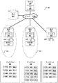
図3は、3つの端末301〜303およびそれらそれぞれのディスプレイ306〜308を備えた分析システム300を示している。端末301は、分析器315のPO領域313内にあるが、分析器316のPO領域314の外側にある。端末302は分析器316のPO領域314内にあるが、分析器315のPO領域313の外側にある。端末303は分析器315、316のPO領域313、314内にはない。これは、たとえば検査室のLIMSを介して、分析システムに接続されたどのようなコンピュータでもよい。
FIG. 3 shows an
分析システム300は、1つの中央コントロールユニット205を備えた1つの中央制御コンピュータシステム304を備えている。分析器、端末および制御コンピュータは、互いにネットワーク305を介して接続されている。設定207は、コントロールユニット205によりアクセス可能なリレーショナルデータベースにより提供される。
The
ディスプレイ306、307、308を介して示されるGUIエレメントが、図3の下部により詳細に示されている。
The GUI elements shown via
ユーザ209は自身のログインデータを入力しても、端末301により分析器のうちの1つの機能の実行を要求してもよい。ディスプレイ306は結果として、それぞれが分析器315のPS機能またはPI機能の実行をユーザがトリガーすることを可能にする、起動可能なPS GUIエレメント320.1、321.1を表示する。さらに、それぞれが、自身の現在位置から分析器316のPS機能またはPI機能を遠隔でユーザがトリガーすることができないことを示す、ドットのボックスで示された起動不可能なPS GUIエレメント322.1、323.1が表示される。これは、ユーザ209が現在分析器315のPO領域313内にある端末301のところにいるが、分析器316のPO領域314の外にいるからである。
The
ユーザ209’は自身のログインデータを入力しても、端末302により分析器のうちの1つの機能の実行を要求してもよい。ディスプレイ307は結果として、それぞれが分析器315のPS機能またはPI機能の実行をユーザがトリガーすることを禁止する、起動不可能なPS GUIエレメント320.2、321.2を表示する。さらに、それぞれが、自身の現在位置から分析器316のPS機能またはPI機能をユーザがトリガー可能であることを示す、起動可能なPS GUIエレメント322.2、323.2が表示される。これは、ユーザ209’が現在分析器316のPO領域314内にある端末302のところにいるが、分析器315のPO領域313の外にいるからである。分析器316の第3の機能は起動可能なPS GUIエレメント324.2により示され、これはディスプレイ307にだけ表示され、遠隔のデータ入力端末のいずれにも表示されない。
The user 209 'may input his login data or may request the terminal 302 to perform one function of the analyzer. Display 307 results in displaying non-activatable PS GUI elements 320.2, 321.2, each prohibiting a user from triggering the execution of the PS function or PI function of
ユーザ209”は自身のログインデータを入力しても、端末303により分析器のうちの1つの機能の実行を要求してもよい。ディスプレイ308は結果として、分析器315に関する起動不可能なPS GUIエレメント320.2、321.2を表示し、分析器316に関する起動不可能なPS GUIエレメント322.1、323.1を表示する。したがって、ユーザは遠隔の端末303から、起動不可能なPS GUIエレメントにより表されたいずれの機能も実行することができない。
The
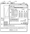
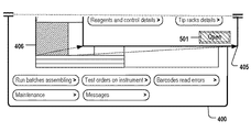
図4は、端末301においてユーザのログイン操作が成功した後、分析器315に関してディスプレイ306を介してユーザに表示される、GUIのメニュー400を示している。このメニューは、異なるGUIウインドウを選択するためのタブ401、402、403を備えている。現在選択されているウインドウのタブ402は、それぞれ分析器または部品、またはその分析器の消耗品を表す、いくつかのGUIエレメント406、409を含んでいる。GUIエレメント406は、たとえば試料セル引き出しなど、分析器315の引き出しを表している。GUIエレメント406を選択すると、第1領域410および第2領域411を含むウインドウが表示される。第1領域は、4つのチップラックA、B、D、Eを表すGUIエレメントを含んでいる。第2ウインドウ領域は、選択されたチップラックの1つのCをより詳細に示している。満たされた試薬容器はボックス「R」で示され、満たされたコントロール容器は、ボックス「C」で示され、空のチップラック容器および試薬容器は空のボックスで示されている。分析器のコンポーネントに関する追加情報の表示のような、「無害」機能を表す、いくつかのGUIエレメント407は、データ入力端末の位置にかかわらず、起動可能なGUIエレメントとして表示される。判定工程103が、データ入力端末301が、そのコンポーネントがGUIエレメント406により表される分析器315のいくつかのPO領域内にあると判定されたので、他のGUIエレメント、たとえば起動可能なPS GUIエレメント408が表示される。
FIG. 4 shows a
図5は、分析器315の引き出しのいくつかの機能を制御するためのメニューを示し、これにより、このメニューのGUIエレメントは、ディスプレイ307を介してユーザ209’に表示されるこれらのGUIエレメントを含んでいる。このGUIエレメントは、少なくとも、起動可能なPS GUIエレメント408の代わりに、起動不可能なPS GUIエレメントが示され、遠隔で分析器315の引き出しのドアの開放をトリガーすることが許可されていないことをユーザに知らせるという点において、ディスプレイ307を介してユーザ209に表示されるGUIエレメントとは異なる。
FIG. 5 shows a menu for controlling some functions of the
図6は、もう1つの実施形態による、起動不可能なPS GUIエレメントを示しており、それにより、ウインドウ602を介して、ユーザは、GUIエレメント602により表された機能をトリガーすることをユーザが許可されていないことを知らされる。このウインドウはさらに、その機能をトリガーすることが許可されていないことについての原因の表示を含んでいてもよく、これはたとえば、その機能を実行する分析器に対して、遠隔の端末にユーザがログインしたなどである。または、ユーザが必要な許可を欠いている、またはユーザが許容できない期間の間に機能を要求した場合であってもよい。さらに、ウインドウ602は、起動不可能なPS GUIエレメントにより表された機能の実行をトリガーするために、ユーザが何をすべきか、および/またはどの端末へ行くべきかについてのヒントを含んでいてもよい。ウインドウ602は、たとえば、GUIエレメント601上に、マウスオーバーされたり、シングルクリックまたはダブルクリックされると表示される、ツールチップまたはポップアップウインドウとして実施されてもよい。
FIG. 6 shows a non-activatable PS GUI element according to another embodiment, via which the user can trigger the function represented by
101、102、103、104、105 工程
205 コントロールユニット
209、209’、209” ユーザ
208 スクリーン
201、210、213、301〜303 第1データ入力端末
201、224、211、300 分析システム
202、212、315、316 分析器
220、221、222、313、314 PO領域
203 プロセッサ
204、215 記憶媒体
208.1、208.2、208.3、306〜308 ディスプレイ
219 PDUモジュール
206、217 レンダリングユニット
207 設定
218 中央演算システム
210 分析器制御コンピュータ
304 中央制御コンピュータシステム
305 ネットワーク
320.1、321.1、322.2、323.2、324.2 起動可能なPS GUIエレメント
320.2、321.2,322.1、323.1 起動不可能なPS GUIエレメント
400 メニュー
401、402、403 タブ
406、407、408、409 GUIエレメント
410 第1領域
411 第2領域
602 ウインドウ
101, 102, 103, 104, 105
Claims (14)
ディスプレイ(208、306〜308)を備えた第1データ入力端末(201、210、213、301〜303)から、ユーザを認証するユーザ(209)のログインデータを受信する受信工程(101)と、
前記第1データ入力端末の位置を記述する情報を取得する工程(102)と、
a)第1データ入力端末の位置が、前記分析器の物理的操作(PO)領域(220〜223、313、314)内にあるかを判定する判定工程(103)とを備え、
b.1)前記第1データ入力端末の位置が前記PO領域内にあると判定された場合は、
前記第1データ入力端末のディスプレイ上に、ユーザが起動可能な位置検出(PS)GUIエレメント(320.1、321.1、322.2、323.2、324.2、408)を表示し(104)、前記起動可能なPS GUIエレメントが、起動されると、前記分析器の機能の実行をトリガーするように構成され、前記機能の実行は、前記分析器による物理的な動作の実行を含むことを特徴とし、
b.2)そうでない場合は、
前記ユーザが起動可能なPS GUIエレメントの表示を禁止する(105)か、または前記機能を示す、起動不可能なPS GUIエレメント(322.1、323.1、320.2、321.2、501、601)を表示することを特徴とし、
前記第1データ入力端末の位置を記述する情報を取得する工程が、前記第1データ入力端末の端末IDを取得する工程を含み、
前記判定工程a)が、
1つまたは2つ以上の端末IDの前記分析器へのマッピングを含む設定(207)にアクセスするアクセス工程であって、IDが前記分析器にマッピングされたそれぞれのデータ入力端末が、前記分析器の前記PO領域内にあることを特徴とする、アクセス工程と、
前記第1データ入力端末の位置が前記分析器の前記PO領域内にあるかを判定するために、取得された前記端末IDが前記分析器にマッピングされたかを判定する工程とを備えることを特徴とするコンピュータを利用する方法。 A method of utilizing a computer to provide access control to the functions of an analyzer (202, 212, 315-317), the method comprising:
A receiving step (101) for receiving login data of a user (209) authenticating the user from a first data input terminal (201, 210, 213, 301-303) provided with a display (208, 306-308);
Obtaining information describing the location of the first data input terminal (102);
a) a determination step (103) for determining whether the position of the first data input terminal is within the physical operation (PO) region (220 to 223, 313, 314) of the analyzer;
b. 1) When it is determined that the position of the first data input terminal is within the PO area,
A position detection (PS) GUI element (320.1, 321.1, 322.2, 323.2, 324.2, 408) that can be activated by the user is displayed on the display of the first data input terminal ( 104) the activatable PS GUI element is configured to trigger execution of the function of the analyzer when activated, execution of the function includes execution of a physical operation by the analyzer It is characterized by
b. 2) If not,
Display of PS GUI elements that can be activated by the user is prohibited (105) or non-activatable PS GUI elements indicating the function (322.1, 323.1, 320.2, 321.2, 501) , 601) are displayed ,
Obtaining the information describing the position of the first data input terminal includes obtaining a terminal ID of the first data input terminal;
The determination step a)
An access step for accessing a setting (207) comprising a mapping of one or more terminal IDs to the analyzer, each data input terminal having an ID mapped to the analyzer, An access step characterized by being in the PO region of
Determining whether the acquired terminal ID is mapped to the analyzer in order to determine whether the position of the first data input terminal is within the PO region of the analyzer. how to use a computer to be.
前記判定工程a)が、
前記分析器の位置に対する、前記第1データ入力端末のLPS位置の空間的距離を判定する工程と、
前記空間的距離が、前記ユーザが前記分析器と物理的なやりとりが可能な最大距離を特定する空間的距離の閾値を下回るかを判定する工程とを備えることを特徴とする請求項1記載のコンピュータを利用する方法。 The step of acquiring information describing the position of the first data input terminal comprises the step of acquiring the LPS position of the first data input terminal, wherein the LPS position is determined by a local positioning system (LPS). And
The determination step a)
Determining a spatial distance of the LPS position of the first data input terminal relative to the position of the analyzer;
The method of claim 1, further comprising: determining whether the spatial distance is below a spatial distance threshold that specifies a maximum distance that the user can physically interact with the analyzer. How to use a computer.
前記第1データ入力端末の端末タイプを示す、端末タイプIDを受信する工程と、
機能IDへの端末タイプIDのマッピングを評価する工程であって、それぞれの端末タイプIDが1つまたは2つ以上の機能のIDにマッピングされ、前記マッピングは、前記端末タイプIDにより表された前記端末タイプが、前記機能IDが前記端末タイプIDへマッピングされた任意の機能をトリガー可能であることを示すことを特徴とする、マッピングを評価する工程とを備え、
前記第1データ入力端末の端末タイプが、前記機能をトリガーすることができないという結果として、前記評価が戻された場合に、工程b.2)が実行され、前記工程b.2)は、前記第1データ入力端末の位置が前記PO領域内であると判定された場合であっても実行されることを特徴とする請求項1または2記載のコンピュータを利用する方法。 The method further comprises:
Indicating the terminal type of the first data input terminal, a step of receiving the terminal type ID,
Evaluating the mapping of terminal type IDs to function IDs, each terminal type ID being mapped to one or more function IDs, wherein the mapping is represented by the terminal type ID Evaluating the mapping, characterized in that the terminal type indicates that the function ID can trigger any function mapped to the terminal type ID, and
If the evaluation is returned as a result of the terminal type of the first data entry terminal being unable to trigger the function, step b. 2) is performed, said step b. 2) a method utilizing a computer according to claim 1 or 2, wherein the position of the first data input terminal is performed even when it is determined to be within the PO region.
前記第1データ入力端末により、ローカルポジショニングシステム(LPS)で自身の位置を自動的に判定する工程と、
前記第1データ入力端末から前記分析器のコントロールユニット(205)へ判定されたLPS位置を送信する工程とを備える請求項1〜3のいずれか1項に記載のコンピュータを利用する方法。 The method further comprises:
Automatically determining its own position in a local positioning system (LPS) by the first data input terminal;
A method using a computer according to any one of claims 1 to 3 , comprising the step of transmitting the determined LPS position from the first data input terminal to a control unit (205) of the analyzer.
前記分析器が、1つまたは2つ以上の位置非検出(PI)機能を実行するように構成され、PI機能のそれぞれは、前記ログインデータを受信する前記第1データ入力端末の現在の位置にかかわらず、その実行が許容される機能であり、
前記方法がさらに、
前記第1データ入力端末から、前記分析器の前記機能を実行するための要求を受信する工程と、
要求された機能が、PS機能のうちの1つまたはPI機能のうちの1つであるかを判定する工程とを備え、
前記要求された機能が前記PS機能の1つである場合、工程a)および工程b)を実行し、
前記要求された機能が前記PI機能の1つである場合、選択されると要求されたPI機能をトリガーするように構成された、ユーザが起動可能なGUIエレメントを表示し、実行されるこの表示が、取得された前記第1データ入力端末の位置が前記PO領域内にあると判断されるかどうかに無関係であることを特徴とする請求項1〜4のいずれか1項に記載のコンピュータを利用する方法。 The analyzer is configured to perform one or more position detection (PS) functions, each of which determines that the position of the first data input terminal is not within the PO area. Is a function that is prohibited from
The analyzer is configured to perform one or more non-position detection (PI) functions, each of the PI functions at a current position of the first data input terminal that receives the login data. Regardless, it is a function that is allowed to execute,
The method further comprises:
Receiving a request from the first data input terminal to perform the function of the analyzer;
Determining whether the requested function is one of the PS functions or one of the PI functions;
If the requested function is one of the PS functions, perform steps a) and b)
If the requested function is one of the PI functions, this display that is executed and displays a user-activatable GUI element configured to trigger the requested PI function when selected. The computer according to any one of claims 1 to 4 , wherein the computer is independent of whether or not the acquired position of the first data input terminal is determined to be within the PO area. How to use.
前記分析器のハウジングを開放または閉鎖すること、前記分析器に消耗品を充填または再充填すること、前記分析器で実行される試料処理ワークフローを開始すること、前記分析器のドアをロックすること、前記分析器のドアのロックを解除すること、前記分析器に生体試料を搭載すること、および、前記分析器から生体試料を下ろすこと
からなる群から選択される請求項5記載のコンピュータを利用する方法。 The one or more PS functions are
Opening or closing the analyzer housing, filling or refilling the analyzer with consumables, initiating a sample processing workflow performed on the analyzer, locking the analyzer door 6. The computer according to claim 5 , wherein the computer is selected from the group consisting of unlocking the analyzer door, mounting a biological sample on the analyzer, and lowering the biological sample from the analyzer. how to.
前記分析器を始動すること、試料処理ワークフローを一時停止または停止すること、前記分析器をシャットダウンすること、前記分析器を休止状態にすること、前記分析器を立ち上げること、前記分析器により収集された測定データを、LIMSまたは他のデータ入力端末に送ること、データ管理機能を実行すること、および試料処理工程を繰り返すこと
からなる群から選択される請求項5または6記載のコンピュータを利用する方法。 The one or more PI functions are
Starting the analyzer, pausing or stopping the sample processing workflow, shutting down the analyzer, putting the analyzer to a dormant state, starting the analyzer, collecting by the analyzer 7. Utilizing a computer according to claim 5 or 6 selected from the group consisting of sending measured measurement data to a LIMS or other data input terminal, performing a data management function, and repeating a sample processing step Method.
工程b.1)で表示された起動可能なPS GUIエレメントが起動すると、前記第1データ入力端末により、その実行がトリガーされるべき機能を示す信号を受信する工程と、
前記第1データ入力端末から前記分析器のコントロールユニットに、前記分析器により実行されるべき機能を特定する要求を自動的に送信する工程と
を備えることを特徴とする請求項1〜7のいずれか1項に記載のコンピュータを利用する方法。 The method further comprises:
Step b. When the activatable PS GUI element displayed in 1) is activated, the first data input terminal receives a signal indicating a function whose execution is to be triggered;
The control unit of the analyzer from the first data input terminal, any of claim 1 to 7, characterized in that it comprises a step of sending a request for identifying a function to be performed by the analyzer automatically A method of using the computer according to claim 1.
前記コントロールユニットによって、前記第1データ入力端末から前記要求を受信する工程と、
前記要求を受信すると、前記コントロールユニットによって、前記機能を実行するためのコマンドを前記分析器に送信する工程と、
前記コマンドに応じて、前記分析器により示された機能が実行される工程とを備えることを特徴とする請求項8記載のコンピュータを利用する方法。 The method further comprises:
Receiving the request from the first data input terminal by the control unit;
Receiving the request, by the control unit, sending a command to perform the function to the analyzer;
The method using a computer according to claim 8 , further comprising: executing a function indicated by the analyzer in response to the command.
前記第1データ入力端末のレンダリングユニット(206)により、前記分析器のコントロールユニットから、ディスプレイを介してユーザに表示される1つまたは2つ以上のGUIエレメントを特定するレンダリングコマンドを受信する工程と、
受信されたレンダリングコマンドに応じて、前記1つまたは2つ以上のGUIエレメントを表示する工程とを備え、
前記レンダリングコマンドの特定が、工程a)の結果に依存することを特徴とする請求項1〜9のいずれか1項に記載のコンピュータを利用する方法。 The method further comprises:
Receiving a rendering command identifying one or more GUI elements displayed to a user via a display from a control unit of the analyzer by a rendering unit ( 206 ) of the first data input terminal; ,
Displaying the one or more GUI elements in response to a received rendering command;
10. The method using a computer according to any one of claims 1 to 9 , wherein the specification of the rendering command depends on a result of step a).
前記少なくとも1つのコントロールユニットが、
ディスプレイ(208、306〜308)を備えた第1データ入力端末(201、210、213、301〜303)から、ユーザ(209)のログインデータを受信する(101)ように構成され、前記ログインデータは、前記1つまたは2つ以上の分析器(202、212、315〜317)のうちの少なくとも1つにおいてユーザを認証し、
前記少なくとも1つのコントロールユニットが、
前記第1データ入力端末の位置を記述する情報を取得するように構成され、
a)前記第1データ入力端末の位置が、前記分析器の物理的操作(PO)領域(220〜223、313、314)内にあるかを判定し(103)、
b.1)前記第1データ入力端末の位置が前記PO領域内にあると判定された場合は、前記第1データ入力端末のディスプレイ上に、ユーザが起動可能な位置検出(PS)GUIエレメント(320.1、321.1、322.2、323.2、324.2、408)の表示(104)をトリガーし、前記起動可能なPS GUIエレメントは、起動されると、1つの分析器の機能の実行をトリガーするように構成され、前記機能の実行は、前記分析器による物理的な動作の実行を含み、
b.2)そうでない場合は、前記ユーザが起動可能なPS GUIエレメントの表示を禁止する(105)か、または前記機能を示す、起動不可能なPS GUIエレメント(322.1、323.1、320.2、321.2、501、601)を表示し、
前記少なくとも1つのコントロールユニットがさらに、前記第1データ入力端末の端末IDを取得するように構成され、以下の工程、すなわち、
1つまたは2つ以上の端末IDの前記分析器へのマッピングを含む設定(207)にアクセスするアクセス工程であって、IDが前記分析器にマッピングされたそれぞれのデータ入力端末が、前記分析器の前記PO領域内にあることを特徴とする、アクセス工程と、
前記第1データ入力端末の位置が前記分析器の前記PO領域内にあるかを判定するために、取得された前記端末IDが前記分析器にマッピングされたかを判定する工程と
を実行するように構成されることを特徴とする分析システム。 An analysis system (201, 224, 211) comprising one or more analyzers and at least one control unit,
The at least one control unit comprises:
The login data is configured to receive (101) login data of a user (209) from a first data input terminal (201, 210, 213, 301 to 303) having a display (208, 306 to 308). Authenticates the user in at least one of the one or more analyzers (202, 212, 315-317);
The at least one control unit comprises:
Configured to obtain information describing a location of the first data input terminal;
a) determining whether the position of the first data input terminal is within the physical operation (PO) area (220-223, 313, 314) of the analyzer (103);
b. 1) If it is determined that the position of the first data input terminal is within the PO area, a position detection (PS) GUI element (320. 1, 321.1, 322.2, 323.2, 324.2, 408), and when the activatable PS GUI element is activated, the function of one analyzer is configured to trigger the execution, execution of the function includes the execution of a physical operation by the analyzer,
b. 2) Otherwise, display of PS GUI elements that can be activated by the user is prohibited (105) or non-activatable PS GUI elements (322.1, 323.1, 320. 2,321.2,501,601) to display the,
The at least one control unit is further configured to obtain a terminal ID of the first data input terminal, and includes the following steps:
An access step for accessing a setting (207) comprising a mapping of one or more terminal IDs to the analyzer, each data input terminal having an ID mapped to the analyzer, An access step characterized by being in the PO region of
Determining whether the acquired terminal ID is mapped to the analyzer to determine whether the position of the first data input terminal is within the PO region of the analyzer;
Analysis system according to claim Rukoto is configured to run.
第1データ入力端末および前記第1データ入力端末のディスプレイを備え、前記ディスプレイが、前記ユーザが起動可能なPS GUIエレメントおよび/または前記起動不可能なPS GUIエレメントを表示するように構成され、
前記第1データ入力端末は、
自身の端末IDおよび/またはローカルポジショニングシステム(LPS)による、自身のLPS位置を自動的に判定し、
判定されたLPS位置および/または判定された端末IDを、前記第1データ入力端末から前記分析器の前記コントロールユニットへ送信するように構成されていることを特徴とする請求項12記載の分析システム。 The analysis system further includes:
Comprising a first data entry terminal and a display of the first data entry terminal, wherein the display is configured to display the user-activatable PS GUI element and / or the non-activatable PS GUI element;
The first data input terminal is
Automatically determine your LPS location by your terminal ID and / or local positioning system (LPS),
13. The analysis system according to claim 12 , wherein the determined LPS position and / or the determined terminal ID are configured to be transmitted from the first data input terminal to the control unit of the analyzer. .
それぞれディスプレイを含んだ1つまたは2つ以上の第2データ入力端末を備え、前記第1データ入力端末が前記少なくとも1つの分析器の前記PO領域内にあり、前記第2データ入力端末のうち少なくとも1つが、前記少なくとも1つの分析器のPO領域内になく、 前記第1データ入力端末は、前記第1データ入力端末から前記ユーザからのログインデータを受信すると、前記起動可能なPS GUIエレメントを表示するように構成され、前記受信に続いて工程a)および工程b)が実行され、前記ログインデータは、少なくとも1つの分析器においてユーザを認証し、
前記第2データ入力端末は、前記第2データ入力端末のうち少なくとも1つから前記ユーザのログインデータを受信すると、前記起動不可能なPS GUIエレメントを表示するように構成され、前記受信に続いて工程a)および工程b)が実行され、前記ログインデータは少なくとも1つの分析器においてユーザを認証することを特徴とする請求項12または13記載の分析システム。 The analysis system further includes:
One or more second data input terminals each including a display, wherein the first data input terminal is in the PO region of the at least one analyzer and at least one of the second data input terminals One is not within the PO area of the at least one analyzer, and the first data input terminal displays the startable PS GUI element upon receiving login data from the user from the first data input terminal And following the reception, steps a) and b) are performed, wherein the login data authenticates a user at at least one analyzer;
The second data input terminal is configured to display the unbootable PS GUI element upon receiving the user login data from at least one of the second data input terminals, and following the reception 14. The analysis system according to claim 12 or 13 , wherein step a) and step b) are performed and the login data authenticates a user at at least one analyzer.
Applications Claiming Priority (2)
| Application Number | Priority Date | Filing Date | Title |
|---|---|---|---|
| EP12157836.3 | 2012-03-02 | ||
| EP12157836.3A EP2634723B1 (en) | 2012-03-02 | 2012-03-02 | Determination of a terminal's position for displaying a gui element |
Publications (2)
| Publication Number | Publication Date |
|---|---|
| JP2013183456A JP2013183456A (en) | 2013-09-12 |
| JP6164870B2 true JP6164870B2 (en) | 2017-07-19 |
Family
ID=45808234
Family Applications (1)
| Application Number | Title | Priority Date | Filing Date |
|---|---|---|---|
| JP2013036034A Active JP6164870B2 (en) | 2012-03-02 | 2013-02-26 | Determining the terminal location for displaying GUI elements |
Country Status (3)
| Country | Link |
|---|---|
| US (1) | US9696864B2 (en) |
| EP (2) | EP3553690B8 (en) |
| JP (1) | JP6164870B2 (en) |
Families Citing this family (11)
| Publication number | Priority date | Publication date | Assignee | Title |
|---|---|---|---|---|
| WO2015042688A1 (en) * | 2013-09-24 | 2015-04-02 | Enable Training And Consulting, Inc. | Systems and methods for remote learning |
| US9363264B2 (en) * | 2013-11-25 | 2016-06-07 | At&T Intellectual Property I, L.P. | Networked device access control |
| US20150187137A1 (en) * | 2013-12-31 | 2015-07-02 | Daqri, Llc | Physical object discovery |
| CN104834839B (en) * | 2014-02-11 | 2019-08-23 | 阿里巴巴集团控股有限公司 | A kind of code generating method, method for authenticating and associated terminal based on bar code |
| CN104335523B (en) * | 2014-04-15 | 2018-08-21 | 华为技术有限公司 | A kind of authority control method, client and server |
| US11262899B2 (en) | 2014-09-10 | 2022-03-01 | Lego A/S | Method for establishing a functional relationship between input and output functions |
| US10812957B2 (en) | 2014-09-10 | 2020-10-20 | Lego A/S | Method for establishing a wireless connection between electronic devices |
| US9911942B2 (en) * | 2016-05-04 | 2018-03-06 | Samsung Display Co., Ltd. | Electronic device and display module provided therein |
| CN110058910A (en) * | 2019-03-08 | 2019-07-26 | 佛山市云米电器科技有限公司 | A kind of design method and system of differentiation interactive interface |
| EP4338161A1 (en) | 2021-05-11 | 2024-03-20 | F. Hoffmann-La Roche AG | Method for operating a laboratory automation system, laboratory automation system, and laboratory in-vitro diagnostic system |
| EP4361642A1 (en) * | 2022-10-26 | 2024-05-01 | ARKRAY, Inc. | Analysis device, method for restricting function, and non-transitory storage medium |
Family Cites Families (81)
| Publication number | Priority date | Publication date | Assignee | Title |
|---|---|---|---|---|
| JPH06112989A (en) * | 1992-09-28 | 1994-04-22 | Horiba Ltd | Analysis system |
| US5548764A (en) * | 1993-04-30 | 1996-08-20 | Advanced Micro Devices, Inc. | Power interrupt device with remote activity detector |
| US5550968A (en) * | 1994-04-12 | 1996-08-27 | International Business Machines Corporation | Method and system for providing access security to controls in a graphical user interface |
| US5897989A (en) * | 1996-07-23 | 1999-04-27 | Beecham; James E. | Method, apparatus and system for verification of infectious status of humans |
| US6804726B1 (en) * | 1996-05-22 | 2004-10-12 | Geovector Corporation | Method and apparatus for controlling electrical devices in response to sensed conditions |
| US5841975A (en) * | 1996-12-10 | 1998-11-24 | The Regents Of The University Of California | Method and apparatus for globally-accessible automated testing |
| US6002427A (en) * | 1997-09-15 | 1999-12-14 | Kipust; Alan J. | Security system with proximity sensing for an electronic device |
| US6570610B1 (en) * | 1997-09-15 | 2003-05-27 | Alan Kipust | Security system with proximity sensing for an electronic device |
| US6085227A (en) * | 1998-03-20 | 2000-07-04 | International Business Machines Corporation | System and method for operating scientific instruments over wide area networks |
| EP0952452B1 (en) * | 1998-04-21 | 2005-07-20 | Hitachi, Ltd. | Automatic analyzer capable of restricting usable operation functions |
| US6563430B1 (en) * | 1998-12-11 | 2003-05-13 | Koninklijke Philips Electronics N.V. | Remote control device with location dependent interface |
| US7058414B1 (en) * | 2000-05-26 | 2006-06-06 | Freescale Semiconductor, Inc. | Method and system for enabling device functions based on distance information |
| US7260094B1 (en) * | 1998-12-22 | 2007-08-21 | Aol Llc | Localization of clients and servers |
| US6957075B1 (en) * | 1999-02-01 | 2005-10-18 | Intel Corporation | Method and apparatus for providing a location based appliance personality |
| US6246862B1 (en) * | 1999-02-03 | 2001-06-12 | Motorola, Inc. | Sensor controlled user interface for portable communication device |
| US6594762B1 (en) * | 1999-05-05 | 2003-07-15 | Ericsson Inc. | Methods and devices enabling displays of electronic devices based on separation thereof |
| US6971072B1 (en) * | 1999-05-13 | 2005-11-29 | International Business Machines Corporation | Reactive user interface control based on environmental sensing |
| IL131195A0 (en) * | 1999-08-01 | 2001-01-28 | Fourier Systems Ltd | Remote laboratory |
| JP3726613B2 (en) * | 2000-02-04 | 2005-12-14 | コニカミノルタビジネステクノロジーズ株式会社 | Information device system, information device management apparatus, information device management method, and computer-readable recording medium recording information device management program |
| KR100385020B1 (en) * | 2000-03-02 | 2003-05-22 | 삼성전자주식회사 | An automatic security code verifying method of a computer system operated by a remote controller |
| US6792321B2 (en) * | 2000-03-02 | 2004-09-14 | Electro Standards Laboratories | Remote web-based control |
| AT412196B (en) * | 2000-03-17 | 2004-11-25 | Keba Ag | METHOD FOR ASSIGNING A MOBILE OPERATING AND / OR OBSERVATION DEVICE TO A MACHINE AND OPERATING AND / OR OBSERVATION DEVICE THEREFOR |
| CA2417659A1 (en) * | 2000-08-01 | 2002-02-07 | Rensselaer Polytechnic Institute | Conducting remote instructor-controlled experimentation |
| US6686838B1 (en) * | 2000-09-06 | 2004-02-03 | Xanboo Inc. | Systems and methods for the automatic registration of devices |
| US6792320B2 (en) * | 2001-01-30 | 2004-09-14 | Fideris, Inc. | Remote change of state for laboratory equipment |
| JP3925208B2 (en) * | 2001-02-09 | 2007-06-06 | セイコーエプソン株式会社 | Data output system, output control terminal, terminal program, and data output method |
| US20060242276A1 (en) * | 2001-02-16 | 2006-10-26 | Lumenare Networks | System and method for remotely configuring testing laboratories |
| US6766279B2 (en) * | 2001-03-01 | 2004-07-20 | Parkinelmer Instruments Llc | System for remote monitoring and control of an instrument |
| US7674298B1 (en) * | 2001-03-30 | 2010-03-09 | Mcafee, Inc. | Method and apparatus for implementing a handheld security system |
| WO2002086843A1 (en) * | 2001-04-02 | 2002-10-31 | Florida Atlantic University | Remote laboratory experimentation |
| JP2002358284A (en) * | 2001-06-01 | 2002-12-13 | Seiko Epson Corp | Service providing system and service providing device |
| KR100442170B1 (en) * | 2001-10-05 | 2004-07-30 | (주)아이디스 | Remote Control and Management System |
| US7591020B2 (en) * | 2002-01-18 | 2009-09-15 | Palm, Inc. | Location based security modification system and method |
| JP4196584B2 (en) * | 2002-03-18 | 2008-12-17 | 富士機械製造株式会社 | Circuit board manufacturing apparatus having management adjustment mode protection function and operation method thereof |
| US7491367B2 (en) * | 2002-06-04 | 2009-02-17 | Applera Corporation | System and method for providing a standardized state interface for instrumentation |
| US7170422B2 (en) * | 2002-06-24 | 2007-01-30 | Matsushita Electric Industrial Co., Ltd. | Personal programmable universal remote control |
| US7275156B2 (en) * | 2002-08-30 | 2007-09-25 | Xerox Corporation | Method and apparatus for establishing and using a secure credential infrastructure |
| US7185288B2 (en) * | 2003-07-18 | 2007-02-27 | Dade Behring Inc. | Operator interface module segmented by function in an automatic clinical analyzer |
| US7064675B2 (en) * | 2003-08-15 | 2006-06-20 | Microsoft Corporation | Context-sensitive remote controls |
| US20050136509A1 (en) * | 2003-09-10 | 2005-06-23 | Bioimagene, Inc. | Method and system for quantitatively analyzing biological samples |
| US20050090267A1 (en) * | 2003-10-24 | 2005-04-28 | Kotzin Michael D. | Method and apparatus for enabling a device by proximity |
| US7319395B2 (en) * | 2003-11-24 | 2008-01-15 | Black & Decker Inc. | Wireless asset monitoring and security system using user identification tags |
| US7660004B2 (en) * | 2004-02-17 | 2010-02-09 | Oracle International Corporation | System and method for detecting accidental output to a device |
| US20050221841A1 (en) * | 2004-03-31 | 2005-10-06 | Piccionelli Gregory A | Location-based control of functions of electronic devices |
| JP4706262B2 (en) | 2004-05-21 | 2011-06-22 | 日本電気株式会社 | Access control system, access control method, and access control program |
| US20050266857A1 (en) * | 2004-05-27 | 2005-12-01 | Nokia Corporation | Location based execution rights |
| US8069239B2 (en) * | 2004-07-20 | 2011-11-29 | Beckman Coulter, Inc. | Centralized monitor and control system for laboratory instruments |
| US20060068834A1 (en) * | 2004-09-30 | 2006-03-30 | Jones Paul H | Method and apparatus for detachable and configurable user interfaces for ultrasound systems |
| SE0402696D0 (en) * | 2004-11-04 | 2004-11-04 | Abb Ab | Industrial robot system |
| US7400891B2 (en) * | 2004-11-10 | 2008-07-15 | At&T Delaware Intellectual Property, Inc. | Methods, systems and computer program products for remotely controlling wireless terminals |
| US7257374B1 (en) * | 2004-12-10 | 2007-08-14 | Cingular Wireless Ii, Llc | Automatic security locking method and system for wireless-enabled devices |
| US7532965B2 (en) * | 2005-01-25 | 2009-05-12 | Johnson Controls Technology Company | System and method for providing user interface functionality based on location |
| JP2008532048A (en) * | 2005-03-07 | 2008-08-14 | ノブックス システムズ インコーポレーテッド | Automatic analyzer |
| US20080010015A1 (en) * | 2006-07-06 | 2008-01-10 | Luke Timothy P | Bundle location specified in terms of gps coordinates |
| US8072309B2 (en) * | 2006-09-14 | 2011-12-06 | Crown Equipment Corporation | Systems and methods of remotely controlling a materials handling vehicle |
| JP4407691B2 (en) * | 2006-11-20 | 2010-02-03 | ソニー株式会社 | COMMUNICATION DEVICE, COMMUNICATION DEVICE PROTECTION METHOD, AND PROGRAM |
| JP4870540B2 (en) * | 2006-12-12 | 2012-02-08 | 株式会社日立製作所 | Printer selection support apparatus and system via network |
| JP4375403B2 (en) * | 2007-01-15 | 2009-12-02 | コニカミノルタビジネステクノロジーズ株式会社 | Information processing apparatus and information processing program |
| US8761712B1 (en) * | 2007-01-23 | 2014-06-24 | Control4 Corporation | Location based remote controller for controlling different electronic devices located in different locations |
| US7676750B2 (en) * | 2007-01-31 | 2010-03-09 | Lexmark International, Inc. | Method of printing, scanning, and faxing using device location |
| US7840237B2 (en) * | 2007-02-08 | 2010-11-23 | Microsoft Corporation | Enabling user interface elements based on short range wireless devices |
| EP1986013A3 (en) * | 2007-04-27 | 2013-04-03 | Sysmex Corporation | Sample analyzing apparatus |
| WO2009007148A1 (en) * | 2007-07-10 | 2009-01-15 | International Business Machines Corporation | System and method of controlling access to services |
| US9244455B2 (en) * | 2007-09-10 | 2016-01-26 | Fisher-Rosemount Systems, Inc. | Location dependent control access in a process control system |
| KR101421164B1 (en) * | 2007-12-18 | 2014-07-18 | 엘지전자 주식회사 | Mobile terminal and its method for displaying radio device |
| US7973657B2 (en) * | 2008-02-20 | 2011-07-05 | Mourad Ben Ayed | Systems for monitoring proximity to prevent loss or to assist recovery |
| US8041437B2 (en) * | 2008-04-15 | 2011-10-18 | International Business Machines Corporation | System and method for virtual control of laboratory equipment |
| DE102008036860A1 (en) * | 2008-08-07 | 2010-02-25 | Ika-Werke Gmbh & Co. Kg | Laboratory unit with a laboratory device and a remote control |
| JP5200824B2 (en) * | 2008-09-26 | 2013-06-05 | 富士通モバイルコミュニケーションズ株式会社 | Mobile device |
| US8961619B2 (en) * | 2009-01-06 | 2015-02-24 | Qualcomm Incorporated | Location-based system permissions and adjustments at an electronic device |
| ES2655984T3 (en) * | 2009-05-06 | 2018-02-22 | F. Hoffmann-La Roche Ag | Analysis system, method and product of a computer program for the analysis of biological samples |
| US8112066B2 (en) * | 2009-06-22 | 2012-02-07 | Mourad Ben Ayed | System for NFC authentication based on BLUETOOTH proximity |
| US8458384B2 (en) * | 2010-02-03 | 2013-06-04 | National Instruments Corporation | Automatically launching a measurement application in response to measurement device connection |
| US20110202269A1 (en) * | 2010-02-15 | 2011-08-18 | Avaya Inc. | Mobile gaming, hospitality and communications appliance |
| US8620344B2 (en) * | 2010-04-07 | 2013-12-31 | Apple Inc. | Location-based application program management |
| US8701138B2 (en) * | 2010-04-23 | 2014-04-15 | Time Warner Cable Enterprises Llc | Zone control methods and apparatus |
| US8907782B2 (en) * | 2010-06-30 | 2014-12-09 | Welch Allyn, Inc. | Medical devices with proximity detection |
| US8937534B2 (en) * | 2010-12-08 | 2015-01-20 | At&T Intellectual Property I, L.P. | Remote control of electronic devices via mobile device |
| US20120240220A1 (en) * | 2011-03-15 | 2012-09-20 | Raytheon Company | Method and system for controlling data access on user interfaces |
| US20130127904A1 (en) * | 2011-11-18 | 2013-05-23 | Andrew P. Dove | Automatically Displaying Measurement Data Acquired by a Measurement System on a Mobile Device |
| JP2013117834A (en) * | 2011-12-02 | 2013-06-13 | Canon Inc | Information processing apparatus, method for controlling the same, and control program |
-
2012
- 2012-03-02 EP EP19172612.4A patent/EP3553690B8/en active Active
- 2012-03-02 EP EP12157836.3A patent/EP2634723B1/en active Active
-
2013
- 2013-02-21 US US13/772,482 patent/US9696864B2/en active Active
- 2013-02-26 JP JP2013036034A patent/JP6164870B2/en active Active
Also Published As
| Publication number | Publication date |
|---|---|
| US9696864B2 (en) | 2017-07-04 |
| US20130232425A1 (en) | 2013-09-05 |
| EP2634723B1 (en) | 2019-08-21 |
| EP3553690B1 (en) | 2021-10-13 |
| EP2634723A1 (en) | 2013-09-04 |
| EP3553690A1 (en) | 2019-10-16 |
| JP2013183456A (en) | 2013-09-12 |
| EP3553690B8 (en) | 2021-12-08 |
Similar Documents
| Publication | Publication Date | Title |
|---|---|---|
| JP6164870B2 (en) | Determining the terminal location for displaying GUI elements | |
| US9342702B2 (en) | Controlling an analysis system of biological samples | |
| JP6185868B2 (en) | Method and system for ensuring that sensitive data is inaccessible | |
| US20170142324A1 (en) | Method for generating an entry for an electronic laboratory journal | |
| US9927941B2 (en) | Method for aggregating task data objects and for providing an aggregated view | |
| US8511549B2 (en) | Analysis system for analyzing biological samples, methods, and computer program product thereof | |
| EP3834063B1 (en) | Lab instrument status monitoring | |
| US20110208536A1 (en) | Clinical test information managing apparatus and non-transitory storage medium | |
| US9285379B2 (en) | Information management apparatus and sample testing apparatus that permit functions based upon operator attributes | |
| US20170124274A1 (en) | Medical apparatus, system for controlling medical test request, method for controlling medical test request, and program stored in medium | |
| JP5776206B2 (en) | Analysis system with approval means | |
| US20200219594A1 (en) | Quantification of sequencing instruments and reagents for use in molecular diagnostic methods | |
| JP2014139584A (en) | Specimen inspection device |
Legal Events
| Date | Code | Title | Description |
|---|---|---|---|
| A621 | Written request for application examination |
Free format text: JAPANESE INTERMEDIATE CODE: A621 Effective date: 20160126 |
|
| RD02 | Notification of acceptance of power of attorney |
Free format text: JAPANESE INTERMEDIATE CODE: A7422 Effective date: 20160126 |
|
| A977 | Report on retrieval |
Free format text: JAPANESE INTERMEDIATE CODE: A971007 Effective date: 20161221 |
|
| A131 | Notification of reasons for refusal |
Free format text: JAPANESE INTERMEDIATE CODE: A131 Effective date: 20170131 |
|
| A521 | Request for written amendment filed |
Free format text: JAPANESE INTERMEDIATE CODE: A523 Effective date: 20170406 |
|
| TRDD | Decision of grant or rejection written | ||
| A01 | Written decision to grant a patent or to grant a registration (utility model) |
Free format text: JAPANESE INTERMEDIATE CODE: A01 Effective date: 20170613 |
|
| A61 | First payment of annual fees (during grant procedure) |
Free format text: JAPANESE INTERMEDIATE CODE: A61 Effective date: 20170620 |
|
| R150 | Certificate of patent or registration of utility model |
Ref document number: 6164870 Country of ref document: JP Free format text: JAPANESE INTERMEDIATE CODE: R150 |
|
| R250 | Receipt of annual fees |
Free format text: JAPANESE INTERMEDIATE CODE: R250 |
|
| R250 | Receipt of annual fees |
Free format text: JAPANESE INTERMEDIATE CODE: R250 |
|
| R250 | Receipt of annual fees |
Free format text: JAPANESE INTERMEDIATE CODE: R250 |
|
| R250 | Receipt of annual fees |
Free format text: JAPANESE INTERMEDIATE CODE: R250 |