JP6164540B2 - Low profile lighting system - Google Patents
Low profile lighting system Download PDFInfo
- Publication number
- JP6164540B2 JP6164540B2 JP2015520461A JP2015520461A JP6164540B2 JP 6164540 B2 JP6164540 B2 JP 6164540B2 JP 2015520461 A JP2015520461 A JP 2015520461A JP 2015520461 A JP2015520461 A JP 2015520461A JP 6164540 B2 JP6164540 B2 JP 6164540B2
- Authority
- JP
- Japan
- Prior art keywords
- light
- housing
- plane
- output
- component
- Prior art date
- Legal status (The legal status is an assumption and is not a legal conclusion. Google has not performed a legal analysis and makes no representation as to the accuracy of the status listed.)
- Active
Links
Images


Classifications
-
- F—MECHANICAL ENGINEERING; LIGHTING; HEATING; WEAPONS; BLASTING
- F21—LIGHTING
- F21K—NON-ELECTRIC LIGHT SOURCES USING LUMINESCENCE; LIGHT SOURCES USING ELECTROCHEMILUMINESCENCE; LIGHT SOURCES USING CHARGES OF COMBUSTIBLE MATERIAL; LIGHT SOURCES USING SEMICONDUCTOR DEVICES AS LIGHT-GENERATING ELEMENTS; LIGHT SOURCES NOT OTHERWISE PROVIDED FOR
- F21K9/00—Light sources using semiconductor devices as light-generating elements, e.g. using light-emitting diodes [LED] or lasers
- F21K9/60—Optical arrangements integrated in the light source, e.g. for improving the colour rendering index or the light extraction
- F21K9/61—Optical arrangements integrated in the light source, e.g. for improving the colour rendering index or the light extraction using light guides
-
- F—MECHANICAL ENGINEERING; LIGHTING; HEATING; WEAPONS; BLASTING
- F21—LIGHTING
- F21S—NON-PORTABLE LIGHTING DEVICES; SYSTEMS THEREOF; VEHICLE LIGHTING DEVICES SPECIALLY ADAPTED FOR VEHICLE EXTERIORS
- F21S8/00—Lighting devices intended for fixed installation
- F21S8/02—Lighting devices intended for fixed installation of recess-mounted type, e.g. downlighters
- F21S8/026—Lighting devices intended for fixed installation of recess-mounted type, e.g. downlighters intended to be recessed in a ceiling or like overhead structure, e.g. suspended ceiling
-
- G—PHYSICS
- G02—OPTICS
- G02B—OPTICAL ELEMENTS, SYSTEMS OR APPARATUS
- G02B6/00—Light guides; Structural details of arrangements comprising light guides and other optical elements, e.g. couplings
- G02B6/0001—Light guides; Structural details of arrangements comprising light guides and other optical elements, e.g. couplings specially adapted for lighting devices or systems
- G02B6/0011—Light guides; Structural details of arrangements comprising light guides and other optical elements, e.g. couplings specially adapted for lighting devices or systems the light guides being planar or of plate-like form
- G02B6/0033—Means for improving the coupling-out of light from the light guide
- G02B6/0035—Means for improving the coupling-out of light from the light guide provided on the surface of the light guide or in the bulk of it
- G02B6/0045—Means for improving the coupling-out of light from the light guide provided on the surface of the light guide or in the bulk of it by shaping at least a portion of the light guide
- G02B6/0046—Tapered light guide, e.g. wedge-shaped light guide
-
- F—MECHANICAL ENGINEERING; LIGHTING; HEATING; WEAPONS; BLASTING
- F21—LIGHTING
- F21V—FUNCTIONAL FEATURES OR DETAILS OF LIGHTING DEVICES OR SYSTEMS THEREOF; STRUCTURAL COMBINATIONS OF LIGHTING DEVICES WITH OTHER ARTICLES, NOT OTHERWISE PROVIDED FOR
- F21V2200/00—Use of light guides, e.g. fibre optic devices, in lighting devices or systems
- F21V2200/20—Use of light guides, e.g. fibre optic devices, in lighting devices or systems of light guides of a generally planar shape
-
- F—MECHANICAL ENGINEERING; LIGHTING; HEATING; WEAPONS; BLASTING
- F21—LIGHTING
- F21W—INDEXING SCHEME ASSOCIATED WITH SUBCLASSES F21K, F21L, F21S and F21V, RELATING TO USES OR APPLICATIONS OF LIGHTING DEVICES OR SYSTEMS
- F21W2131/00—Use or application of lighting devices or systems not provided for in codes F21W2102/00-F21W2121/00
- F21W2131/10—Outdoor lighting
-
- F—MECHANICAL ENGINEERING; LIGHTING; HEATING; WEAPONS; BLASTING
- F21—LIGHTING
- F21Y—INDEXING SCHEME ASSOCIATED WITH SUBCLASSES F21K, F21L, F21S and F21V, RELATING TO THE FORM OR THE KIND OF THE LIGHT SOURCES OR OF THE COLOUR OF THE LIGHT EMITTED
- F21Y2105/00—Planar light sources
-
- F—MECHANICAL ENGINEERING; LIGHTING; HEATING; WEAPONS; BLASTING
- F21—LIGHTING
- F21Y—INDEXING SCHEME ASSOCIATED WITH SUBCLASSES F21K, F21L, F21S and F21V, RELATING TO THE FORM OR THE KIND OF THE LIGHT SOURCES OR OF THE COLOUR OF THE LIGHT EMITTED
- F21Y2115/00—Light-generating elements of semiconductor light sources
- F21Y2115/10—Light-emitting diodes [LED]
-
- G—PHYSICS
- G02—OPTICS
- G02B—OPTICAL ELEMENTS, SYSTEMS OR APPARATUS
- G02B6/00—Light guides; Structural details of arrangements comprising light guides and other optical elements, e.g. couplings
- G02B6/0001—Light guides; Structural details of arrangements comprising light guides and other optical elements, e.g. couplings specially adapted for lighting devices or systems
- G02B6/0011—Light guides; Structural details of arrangements comprising light guides and other optical elements, e.g. couplings specially adapted for lighting devices or systems the light guides being planar or of plate-like form
- G02B6/0066—Light guides; Structural details of arrangements comprising light guides and other optical elements, e.g. couplings specially adapted for lighting devices or systems the light guides being planar or of plate-like form characterised by the light source being coupled to the light guide
- G02B6/0073—Light emitting diode [LED]
-
- Y—GENERAL TAGGING OF NEW TECHNOLOGICAL DEVELOPMENTS; GENERAL TAGGING OF CROSS-SECTIONAL TECHNOLOGIES SPANNING OVER SEVERAL SECTIONS OF THE IPC; TECHNICAL SUBJECTS COVERED BY FORMER USPC CROSS-REFERENCE ART COLLECTIONS [XRACs] AND DIGESTS
- Y10—TECHNICAL SUBJECTS COVERED BY FORMER USPC
- Y10T—TECHNICAL SUBJECTS COVERED BY FORMER US CLASSIFICATION
- Y10T29/00—Metal working
- Y10T29/49—Method of mechanical manufacture
- Y10T29/49826—Assembling or joining
Description
本開示は照明システムに関し、特にロープロファイル光ウォッシュシステム(low-profile light wash systems)に関する。 The present disclosure relates to lighting systems, and more particularly to low-profile light wash systems.
ウォールウォッシュシステムのような照明システムは、照明すべき壁または天井の一区画にわたって実質的に均一な照明パターンをもたらすのに使用することができる。そのような照明システムは、たとえば、部屋全体または部屋の一部分を照明することなく特定の領域の均一な照明が必要とされる、アートギャラリーまたは同様の場所に使用することができる。従来のウォールウォッシュシステムは、照明すべき壁の一区画にわたって実質的に均一な光ウォッシュを達成するために、放物面反射器を利用する。 An illumination system, such as a wall wash system, can be used to provide a substantially uniform illumination pattern across a section of the wall or ceiling to be illuminated. Such lighting systems can be used, for example, in art galleries or similar places where uniform illumination of a specific area is required without illuminating the entire room or a portion of the room. Conventional wall wash systems utilize a parabolic reflector to achieve a substantially uniform light wash over a section of the wall to be illuminated.
このような放物面反射器を使用することによって、ウォールウォッシュシステムのサイズが大幅に増大し、ウォールウォッシュシステムを使用するにあたって大幅な制約が課される。 By using such a parabolic reflector, the size of the wall wash system is greatly increased and significant restrictions are imposed on the use of the wall wash system.
本開示のシステム、方法およびデバイスは、それぞれいくつかの発明的態様を有し、それらのうちの単一の態様だけが、本明細書で開示する望ましい属性に関与するとは限らない。 Each of the systems, methods and devices of the present disclosure has several inventive aspects, not only a single aspect of which is involved in the desired attributes disclosed herein.
本開示で説明する主題の1つの発明的態様は、ハウジングであって、前記ハウジングは、導光路から一定斜角で出射するコリメート光を受けるように構成されている入力開口、および、入力開口に対して一定角度に向けられ、光がハウジングを出射することを可能にするように構成されている出力開口を含む、ハウジングと、出力開口内に配置されている光学フィルムの積層体であって、前記光学フィルムの積層体は、出力開口を通してハウジングを出射する光に対して、出力開口から所定の距離にある平面内に所望の光パターンを投影するように動作するように構成されている、光学フィルムの積層体と、を含む照明器具構成要素において実装することができる。 One inventive aspect of the subject matter described in the present disclosure is a housing, the housing being configured to receive collimated light exiting from the light guide at a constant oblique angle, and the input opening A laminate of a housing and an optical film disposed within the output aperture, the output aperture being configured to be directed at an angle relative to and configured to allow light to exit the housing; The optical film laminate is configured to operate to project a desired light pattern in a plane at a predetermined distance from the output aperture for light exiting the housing through the output aperture. And can be implemented in luminaire components including a laminate of films.
一態様において、光学フィルムの積層体によって投影される光パターンは、入力開口の平面から65度以下の角度にある軸に沿って中心を置かれ得る。一態様において、光学フィルムの積層体は、出力開口から所定の距離にある平面内に実質的に均一な光のウォッシュ(wash)を投影するように構成することができ、前記平面は、入力開口の平面に実質的に直交する。一態様において、光学フィルムの積層体は、少なくとも第1のレンチキュラフィルムを含むことができる。さらなる一態様において、光学フィルムの積層体は、第2のレンチキュラフィルムおよびディフューザのうちの少なくとも一方を含むことができる。一態様において、光学フィルムの積層体は、非対称レンチキュラフィルムを含むことができる。一態様において、光学フィルムの積層体は、単一の光学フィルムから構成することができる。 In one aspect, the light pattern projected by the stack of optical films may be centered along an axis that is at an angle of 65 degrees or less from the plane of the input aperture. In one aspect, the stack of optical films can be configured to project a substantially uniform light wash in a plane at a predetermined distance from the output aperture, the plane being the input aperture. Substantially perpendicular to the plane of In one embodiment, the laminate of optical films can include at least a first lenticular film. In a further embodiment, the laminate of optical films can include at least one of a second lenticular film and a diffuser. In one embodiment, the laminate of optical films can include an asymmetric lenticular film. In one embodiment, the laminate of optical films can be composed of a single optical film.
一態様において、照明器具構成要素はハウジング内に配置されている再帰反射器をさらに含むことができ、再帰反射器は、入力開口に入射する光を出力開口に向けて方向転換するように構成されている。さらなる一態様において、再帰反射器は、入力開口に入射するコリメート光を入力開口の平面に対して第1の角度で反射し、前記コリメート光を入力開口の平面に対して第2の角度で反射するように構成することができ、第2の角度は第1の角度よりも大きい。さらなる一態様において、再帰反射器は、ハウジングの他の内部表面よりも反射性が大幅に高いものであり得る。さらなる一態様において、再帰反射器は、第2の反射部分に対して内向きに角度を付けられている第1の反射部分を含むことができる。またさらなる一態様において、第1の反射部分は、第1の平面内で第2の反射部分に対して内向きに角度を付けることができ、照明器具構成要素は、第1の平面に対して一定角度に向けられている第2の平面内で第2の反射部分に対して内向きに角度を付けられている第3の反射部分をさらに含むことができる。さらなる一態様において、再帰反射器は、内向きに湾曲している反射部分を含むことができる。 In one aspect, the luminaire component can further include a retroreflector disposed within the housing, wherein the retroreflector is configured to redirect light incident on the input aperture toward the output aperture. ing. In a further aspect, the retroreflector reflects collimated light incident on the input aperture at a first angle with respect to the plane of the input aperture and reflects the collimated light at a second angle with respect to the plane of the input aperture. And the second angle is greater than the first angle. In a further aspect, the retroreflector can be significantly more reflective than the other interior surfaces of the housing. In a further aspect, the retroreflector can include a first reflective portion that is angled inwardly with respect to the second reflective portion. In yet a further aspect, the first reflective portion can be angled inward with respect to the second reflective portion in the first plane, and the luminaire component is relative to the first plane. A third reflective portion may be further included that is angled inwardly relative to the second reflective portion in a second plane oriented at a constant angle. In a further aspect, the retroreflector can include a reflective portion that is curved inwardly.
一態様において、ハウジングは、ハウジング内の実質的に平行な経路に沿ってコリメート光を送達するように構成することができる。一態様において、ハウジングは、入力開口の平面に実質的に平行な平面内でハウジングから外向きに延在するベゼルをさらに含むことができる。一態様において、照明器具は、入力開口に隣接して配置されている導光路をさらに含み、導光路は、出力面を含み、入力開口を通るコリメート光を、導光路の出力面に対して一定斜角に方向付けるように構成されている。さらなる一態様において、導光路の出力面は、ハウジングの入力開口の平面に対して実質的に平行に向けることができる。 In one aspect, the housing can be configured to deliver collimated light along a substantially parallel path within the housing. In one aspect, the housing can further include a bezel extending outwardly from the housing in a plane substantially parallel to the plane of the input opening. In one aspect, the luminaire further includes a light guide disposed adjacent to the input aperture, the light guide includes an output surface, and collimated light passing through the input aperture is constant with respect to the output surface of the light guide. It is configured to be oriented at an oblique angle. In a further aspect, the output surface of the light guide can be oriented substantially parallel to the plane of the input opening of the housing.
一態様において、照明器具構成要素は、アンカ構成要素をさらに含むことができ、アンカ構成要素は、天井または壁の中に形成される開口に対して固定されるように構成され、ハウジングは、天井または壁の、アンカ構成要素から反対の側でアンカ構成要素に固定されるように構成される。さらなる一態様において、アンカ構成要素は、光源と光学的に連通している少なくとも1つの導光路を支持することができ、導光路は、光源から放出される光をコリメートし、前記コリメート光を、入力開口の平面に対して一定斜角で、入力開口内に方向付けるように構成することができる。 In one aspect, the luminaire component can further include an anchor component, wherein the anchor component is configured to be secured relative to an opening formed in the ceiling or wall, and the housing includes a ceiling Or configured to be secured to the anchor component on the opposite side of the wall from the anchor component. In a further aspect, the anchor component can support at least one light guide that is in optical communication with the light source, the light guide collimating the light emitted from the light source, the collimated light being It can be configured to be directed into the input opening at a constant oblique angle with respect to the plane of the input opening.
本開示に説明する主題の別の発明的態様は、入力開口、および、入力開口に対して一定角度に向けられている出力開口を有するハウジングを提供するステップと、出力開口内に配置されている光学フィルムの積層体を提供するステップと、ハウジングを、入力開口に対して一定斜角で光を放出するように構成されている導光路に対して位置決めし、それによって、光が入力開口を通してハウジングに入射し、光学フィルムの積層体を通過する、位置決めするステップとを含み、光学フィルムの積層体は、前記出力開口を通して前記ハウジングを出射する光に対して、出力開口から所定の距離にある平面内に所望の光パターンを投影するように動作するように構成されている、照明器具を組み立てる方法において実装することができる。 Another inventive aspect of the subject matter described in the present disclosure provides a housing having an input opening and an output opening that is oriented at an angle relative to the input opening; and is disposed within the output opening. Providing a laminate of optical films and positioning the housing relative to a light guide configured to emit light at a constant oblique angle with respect to the input aperture, whereby light is transmitted through the input aperture to the housing And passing through the optical film stack, wherein the optical film stack is a plane at a predetermined distance from the output aperture for light exiting the housing through the output aperture. It can be implemented in a method for assembling a luminaire that is configured to operate to project a desired light pattern therein.
一態様において、方法は、天井または壁の中の開口に隣接して配置されているアンカ構成要素に対して、ハウジングおよびアンカ構成要素を開口に対して固定するように、ハウジングを固定するステップをさらに含むことができ、アンカ構成要素の少なくとも一部分は、天井または壁の、ハウジングの少なくとも一部分から反対の側に配置されている。一態様において、光学フィルムの積層体によって投影される光パターンは、入力開口の平面から65度以下の角度にある軸に沿って中心を置かれ得る。一態様において、ハウジングは、ハウジング内で、導光路から放出されるコリメート光の経路内に配置されている再帰反射器をさらに含むことができ、再帰反射器は、入力開口を通して入射するコリメート光を出力開口内に配置されている光学フィルムの積層体に向けて方向転換するように構成されている。 In one aspect, the method includes securing the housing to an anchor component disposed adjacent to the opening in the ceiling or wall to secure the housing and the anchor component to the opening. Further, at least a portion of the anchor component may be disposed on the opposite side of the ceiling or wall from at least a portion of the housing. In one aspect, the light pattern projected by the stack of optical films may be centered along an axis that is at an angle of 65 degrees or less from the plane of the input aperture. In one aspect, the housing can further include a retroreflector disposed within the housing in the path of the collimated light emitted from the light guide, the retroreflector receiving the collimated light incident through the input aperture. It is comprised so that it may change direction toward the laminated body of the optical film arrange | positioned in an output opening.
本開示に説明する主題の1つの発明的態様は、ハウジングであって、前記ハウジングが、導光路から一定斜角で出射するコリメート光を受けるように構成されている入力開口、および、入力開口に対して一定角度に向けられ、光がハウジングを出射することを可能にするように構成されている出力開口を含む、ハウジングと、出力開口から所定の距離にある平面内に所望の光パターンを投影するために、出力開口を通過する光を変化させるための手段と、を含む照明器具において実装することができる。 One inventive aspect of the subject matter described in the present disclosure is a housing, wherein the housing is configured to receive collimated light that is emitted from the light guide at a constant oblique angle, and to the input opening. Projecting a desired light pattern in a plane that is at a predetermined distance from the housing, including an output aperture that is directed at an angle to the light aperture and configured to allow light to exit the housing In order to do so, it can be implemented in a luminaire comprising means for changing the light passing through the output aperture.
一態様において、光成形手段は、出力開口内に配置されている光学フィルムの積層体を含むことができる。一態様において、光成形手段は、出力開口を通過する光を成形および/または方向付けるように構成することができる。一態様において、光成形手段は、ディフューザおよびレンチキュラフィルムのうちの少なくとも一方を含むことができる。 In one aspect, the light shaping means can include a laminate of optical films disposed within the output aperture. In one aspect, the light shaping means can be configured to shape and / or direct light passing through the output aperture. In one aspect, the light shaping means can include at least one of a diffuser and a lenticular film.
本明細書で説明する主題の1つまたは複数の実施態様の詳細が、添付の図面および下記の説明において示されている。他の特徴、態様、および利点は、説明、図面、および特許請求の範囲から明らかになるであろう。以下の図の相対寸法は一定の縮尺で描かれていないことがあることに留意されたい。 The details of one or more implementations of the subject matter described in this specification are set forth in the accompanying drawings and the description below. Other features, aspects, and advantages will be apparent from the description, drawings, and claims. Note that the relative dimensions in the following figures may not be drawn to scale.
様々な図面中の同様の参照番号および名称は同様の要素を示す。 Like reference numbers and designations in the various drawings indicate like elements.
以下の詳細な説明は、発明的態様について説明する目的で、いくつかの実施態様を対象とする。しかしながら、本明細書の教示は、多数の異なる方法で適用され得る。本教示は、薄型のLEDベースの光エンジンとともに使用するための光ウォッシュシステム、特に、所望のパターンにあるLED光源の出力を方向付けるための導光路を含むLEDベースの光エンジンに適用可能であるが、本教示はまた、大幅にコリメートされたパターンにおいて放出される光に対して動作するように構成されている任意の光ウォッシュシステムにも適用可能であり得る。記載される実施態様は、限定ではないが、商業用、産業用、および住居用の照明のような多種多様な用途に使用される照明に含まれてもよく、または前記照明と関連付けられてもよい。実施態様は、限定ではないが、家庭、オフィス、製造施設、小売場所、病院および診療所、コンベンションセンター、文化施設、図書館、学校、庁舎、倉庫、軍事施設、研究施設、体育館、競技場内の照明、または他のタイプの環境または用途における照明を含んでもよい。様々な実施態様において、照明は、天井の照明であってもよく、スポットライト、または、照明デバイスの発光面の面積よりも大きい(たとえば、数倍大きいまたは何倍も大きい)面積を有する他の光ウォッシュパターンを投影してもよい。したがって、本教示は、単に図に示す実施態様に限定されるものではなく、代わりに、当業者に直ちに明らかになるであろう広い適用性を有する。 The following detailed description is directed to certain embodiments for the purpose of describing inventive aspects. However, the teachings herein can be applied in a number of different ways. The present teachings are applicable to light wash systems for use with thin LED-based light engines, and in particular to LED-based light engines that include a light guide for directing the output of an LED light source in a desired pattern. However, the present teachings may also be applicable to any light wash system that is configured to operate on light emitted in a substantially collimated pattern. The described embodiments may be included in or associated with lighting used in a wide variety of applications such as, but not limited to, commercial, industrial, and residential lighting. Good. Embodiments include, but are not limited to, lighting in homes, offices, manufacturing facilities, retail locations, hospitals and clinics, convention centers, cultural facilities, libraries, schools, government buildings, warehouses, military facilities, research facilities, gymnasiums, stadiums Or may include lighting in other types of environments or applications. In various embodiments, the lighting may be ceiling lighting, or a spotlight or other having an area that is larger (eg, several times larger or many times larger) than the area of the light emitting surface of the lighting device. An optical wash pattern may be projected. Thus, the present teachings are not limited to the embodiments shown in the figures, but instead have wide applicability that will be readily apparent to those skilled in the art.
いくつかの実施形態において、照明デバイスまたは装置は、光エンジン構成要素と、照明デバイスを照明器具に電気的および/または機械的に結合するための接続部分とを含むことができる。本明細書において使用される場合、「照明器具」という用語は、照明デバイス、たとえば、埋め込み型照明ハウジング、ダウンライト器具、カン器具(can fixture)、ポットライト器具、コーブ照明器具、トーチランプ器具、ペンダントライト器具、壁取り付け型照明器具(sconce fixture)、トラックライト、および/またはベイライト器具(bay light fixture)の任意の部分に電気的および/または機械的に結合されるように構成されている任意の器具または構造を指す。 In some embodiments, a lighting device or apparatus can include a light engine component and a connection portion for electrically and / or mechanically coupling the lighting device to a luminaire. As used herein, the term “lighting fixture” refers to a lighting device, such as an embedded lighting housing, a downlight fixture, a can fixture, a potlight fixture, a cove lighting fixture, a torch lamp fixture, Any configured to be electrically and / or mechanically coupled to any part of the pendant light fixture, wall fixture, track light, and / or bay light fixture Refers to an instrument or structure.
従来のウォールウォッシュシステムは、蛍光灯のような実質的な線状光源から放出される光に対して動作する。その光は実質的にすべての方向において均一に放出され得るため、当初は所望の照明領域から離れた方向において光源から放出された光を方向転換するために、かさばる反射器が使用され得る。放物面反射器のような、これらの大型の反射器は必ず、光源の、照明領域から反対の側に配置され、天井に向かって上向きに延在する。出力光をより小さい角度範囲内に対してコリメートする光エンジンを利用することによって、所望の光ウォッシュパターンを生成するためにコンパクトな光方向転換器(light redirector)および成形光学機器を使用することができる。 Conventional wall wash systems operate on light emitted from a substantially linear light source such as a fluorescent lamp. Since the light can be emitted uniformly in substantially all directions, a bulky reflector can be used to redirect the light emitted from the light source initially in a direction away from the desired illumination area. These large reflectors, such as parabolic reflectors, are always located on the opposite side of the light source from the illumination area and extend upwards towards the ceiling. By using a light engine that collimates the output light to a smaller angular range, a compact light redirector and shaping optics can be used to generate the desired light wash pattern. it can.
本開示で説明する主題の特定の実施態様は、1つまたは複数の以下の潜在的な利点を実現するために実施することができる。一定角度にある光を元の入力方向に方向転換する薄型導光路を利用することによって、光エンジンおよび関連構成要素を、天井タイルまたは同様の構造部材に実質的に平行に配置することができる。導光路のこの向きは、光エンジンの薄さと組み合わさって、従来の放物面ウォールウォッシュシステムと比較して必要な頭上空間を大幅に低減し、この薄さによって、照明システムが、天井タイルの上の頭上空間が浅い実施態様においてさえも、周囲の天井タイルと同一平面上にされることが可能になる。いくつかの実施態様において、導光路の出力面は、照明すべき表面に対して概ね90度の角度に向けられ得る。 Particular implementations of the subject matter described in this disclosure can be implemented to realize one or more of the following potential advantages. By utilizing a thin light guide that redirects light at a constant angle to the original input direction, the light engine and related components can be placed substantially parallel to the ceiling tile or similar structural member. This orientation of the light guide, combined with the thinness of the light engine, significantly reduces the required overhead space compared to conventional parabolic wall wash systems, which allows the lighting system to Even in embodiments where the overhead overhead is shallow, it can be coplanar with the surrounding ceiling tiles. In some embodiments, the output surface of the light guide can be oriented at an angle of approximately 90 degrees with respect to the surface to be illuminated.
図1Aは、コリメート光を一定斜角で放出するように構成されている光エンジンの一例の斜視図を示す。光エンジン100は、反射器110の入力開口112に隣接して配置されている光源102を含む。反射器110は、反射器の高さにわたって実質的に一定の断面を有し、エタンデュ(etendue)を保存するように設計された形状を有する反射側壁114と、反射器110の上部および下部に沿った上部平面反射器116aおよび下部平面反射器116bとを含む。内部反射面の形状に対応する外面を有するように示されているが、反射器110は、内部反射面が所望の形状を有する限り、任意の外形を有してもよい。
FIG. 1A shows a perspective view of an example of a light engine that is configured to emit collimated light at a constant oblique angle. The
特定の実施形態において、反射側壁は、放物線の一部分によって表すことができる形状を有してもよく、ただし、対向する反射側壁114は、そのような実施態様において単一の放物線の区画を形成しなくてもよい。そうではなく、側壁114は、互いに対して回転されている単一の放物線の区画を含んでもよく、それによって、これらの放物線区画の延長は、滑らかな頂点ではない角度で交差することになる。
In certain embodiments, the reflective sidewall may have a shape that can be represented by a portion of a parabola, provided that opposing
側壁形状が、入力開口112のサイズに関連する特定の境界条件を満たすとき、側壁は光をコリメートすることができ、入力開口112を通る光入力の広範囲の角度をより狭い範囲の角度に変換する。必要な境界条件が満たされるとき、側壁112の形状に起因するエタンデュの損失はなくなり、光コリメートの効率が増大するが、材料および製造上の制約が何らかのエタンデュの損失をもたらすことがある。
When the sidewall shape meets certain boundary conditions related to the size of the
特に、反射器110の入力開口112と、反射器120の対向端にある出力開口118との間に延在する長手方向軸に直交する断面は、長手方向軸に沿って入力開口112から出力開口118へと移動するにつれて横幅が増大する矩形形状を有することになる。同様に、反射器110の上部および下部にある平面116aおよび116b(図1B参照)の間に延在する横軸に直交する断面は、放物線のような断面を有することになり、この断面は、この放物線のような形状の頂点付近に、反射器110の入力開口112に対応する切頂端部を有する。
In particular, a cross section orthogonal to the longitudinal axis extending between the input opening 112 of the
反射器110の出力開口118は、先細り導光路120の入力面122に隣接して位置決めされる。反射器110から導光路120への光伝達を促進するために、出力開口118は、入力面122の寸法に対応する寸法を有する。先細り導光路120は、三角形側壁124と、上側平面126と、上側平面126の下にあり、上側平面に対して一定角度に向けられている出力平面128と、を含む。
The
入力面122と先細り導光路120の対向端との間に延在する長手方向軸に直交する先細り導光路120の断面は、入力開口112から離れて先細り導光路118の対向端に向かうにつれて長手方向軸に沿った横断方向の高さが低減していく矩形形状を有することになる。同様に、三角形側壁124の間に延在する横軸に直交する断面は、先細り導光路120の横幅にわたって実質的に一定のままである三角形断面を有することになる。
The cross-section of the tapered
図1Bは、図1Aの光エンジンの上面図である。光源102から様々な角度で放出される光104は湾曲している反射側壁によって方向転換され、全体的に反射器110の出力開口118に向かって反射されることが見て取れる。したがって、湾曲している側壁114は概して、上述したように、上部平面116aおよび下部平面116bに平行な経線(meridian)内に光104をコリメートする。この経線内への光のコリメートの量は、少なくとも、湾曲している反射側壁114の正確な形状および反射器110の長手方向長さ、ならびに、光源102内の発光素子の数およびサイズのような他の要因によって制御される。
FIG. 1B is a top view of the light engine of FIG. 1A. It can be seen that the light 104 emitted from the
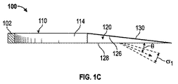
図1Cは、図1Bの1C−1C線に沿ってとられた図1Aの光エンジンの側立断面図である。反射器110を出射し入力面122を通して導光路120に入射する光104(図1B参照)は、導光路120内を伝搬した後に、出力面128を通して導光路120を出射する。出力面128に隣接して配置されている光学フィルムの積層体のような光成形光学機器(図示せず)が、出力面128から放出される出力光104をさらに制御することができる。出力光104は、図示されている実施態様においては導光路120の出力面128に対して浅い斜角θに向けられている中心光線107の辺りに中心を置かれる。
1C is a side sectional view of the light engine of FIG. 1A taken along
導光路120内での光104の伝搬は、内部全反射、または、非出力面(上側平面126および側壁114)の一部もしくは全体を反射層130によって被覆することのいずれかによって制御されてもよい。しかしながら、導光路120の設計は概して、光が反射器110内で以前にコリメートされた経線に直交する第2の経線内で光をコリメートする。図1Cは、出力光104を、概して(紙面内にある)第1の経線内でコリメートされているものとして概略的に示しているが、出力光104は、(紙面に直交する)第2の経線内でもコリメートされることになる。直交経線内でのコリメートの度合いは、必ずしも両方の平面について等しいとは限らない。たとえば、光は、紙面の平面に平行な経線において第1の角度σ1内で、および、角度σ1の経線に直交する経線において第2の角度σ2(図1D参照)内で放出されるようにコリメートされてもよい。たとえば、第1の角度σ1および第2の角度σ2は、ビームの半値全幅を表すことができる。反射器110および先細り導光路120の設計は、光が導光路から放出される斜角θだけでなく、光が放出されたときの両方の経線における拡散の量も制御することを可能にする。
The propagation of the light 104 in the
加えて、光源102から生成される熱の熱管理が、対流熱伝達または伝導性熱伝達のうちの少なくとも一方によって達成されてもよい。一実施態様において、光源102は、対流を介した熱の受動的な放散を可能にする複数の放熱フィン(図1A〜図1Dには示さず、図4参照)と熱連通していてもよい。他の実施態様において、送風機または同様の構成要素を使用することなどを通して、能動冷却がもたらされてもよい。
In addition, thermal management of heat generated from the
光エンジン100のような光エンジンの他の実施態様は、他のまたは代替の構成要素を含むことができる。たとえば、反射器100は、所望の形状の内部反射チャンバをもたらすためにともに組み立てられる2つ以上の構成要素を含んでもよいが、光エンジン100が照明器具の他の構成要素または他の構造的構成要素に固定されることを可能にするためにチャンバの外部に配置される追加の材料を含む。
Other embodiments of the light engine, such as
図1Dは、光エンジンの出力面から放出される例示的な光出力を示す、図1Aの光エンジンの下からの斜視図である。出力光104は、導光路120の出力面128に対して浅い斜角θに向けられている光線107の辺りに中心を置かれる。光出力は、概して両方の経線内でコリメートされるが、概して導光路120の出力面128から一定距離にある平面108内に遠距離場光パターンを投影するように、第1の経線内でσ1の角度にわたって、および、第1の経線に直交する第2の経線内でσ2の角度にわたって拡散する。
FIG. 1D is a perspective view from below of the light engine of FIG. 1A showing an exemplary light output emitted from the output face of the light engine. The
図2は、図1A〜図1Dの光エンジンとともに使用することができる光ウォッシュシステムの一例の断面を示す。いくつかの実施形態において、本明細書に説明する光ウォッシュシステムは、壁の一部分を照明するように構成されているウォールウォッシュシステム(wall wash systems)としての役割を果たしてもよいが、他の実施態様において、光ウォッシュシステムは、天井もしくは床、または出力面に対して任意の角度に向けられている表面もしくは領域の一部分を照明する役割を果たしてもよい。簡便にするために、そのような照明システムを本明細書においては「光ウォッシュシステム」と称する場合があり、照明すべき表面が導光路の出力面に対して一定角度に向けられている(たとえば、照明すべき表面が光エンジンの出力面と非平行である)実施態様は、「傾斜ウォッシュシステム(oblique wash system)」または「傾斜光ウォッシュシステム(oblique light wash system)」と称され得る。 FIG. 2 shows a cross section of an example of an optical wash system that can be used with the light engine of FIGS. 1A-1D. In some embodiments, the light wash systems described herein may serve as wall wash systems that are configured to illuminate a portion of the wall, although other implementations In an aspect, the light wash system may serve to illuminate the ceiling or floor, or a portion of a surface or region that is oriented at any angle with respect to the output surface. For simplicity, such an illumination system may be referred to herein as an “light wash system”, where the surface to be illuminated is oriented at a fixed angle with respect to the output surface of the light guide (eg, Embodiments in which the surface to be illuminated is non-parallel to the output face of the light engine may be referred to as an “oblique wash system” or “oblique light wash system”.
光ウォッシュシステム200は、少なくとも部分的に天井201内の開口を通して延在するように構成されているハウジング204を含み、入力開口210および出力開口220を含む。入力開口210は、入力開口210の上に配置されている光エンジン100から放出される光202を受け入れるような寸法にされており、それによって、光エンジン100の先細り導光路120の出力面128は、入力開口210に隣接して位置する。出力開口220は、入力開口210に対して、導光路120を出射する斜角において入力開口210を通る入力光のすべてまたは相当部分が、ハウジング202の出力開口220を通過することになるような位置に位置する。
The
光学フィルムの積層体230が出力開口220内に、またはそれと整列して配置されており、これは、出力開口220を通過する光202に対して、光成形光学機器230から所定の距離に、かつ光成形光学機器に対して一定角度において位置する平面208内に所望の光パターンを投影する光線207を中心とする光出力206を生成するように動作する。したがって、光学フィルムの積層体230は、本明細書においてより詳細に説明するように、出力開口220から所定の距離にある平面208内に所望の光パターンを投影するために、ハウジング204の出力開口220を通過する光202を変化させるための手段を提供する。光学フィルムの積層体230は、光202を成形および/または方向転換することによって光202を変化させることができる。光ウォッシュシステムが、天井202に隣接する壁上に光を投影するように構成されている実施態様において、平面208は、導光路120の出力面128に直交してもよく、ただし、他の実施態様において、所望の光パターンが投影される平面208は、導光路120の出力面128に平行に、または任意の他の角度に向けられてもよい。
A stack of
図示されている実施態様において、光学フィルムの積層体230は、両方とも入力光の光軸に概ね直交する基平面を有するレンチキュラフィルム232およびディフューザ234を含むものとして示されているが、様々な実施態様において、光学フィルムの積層体は、光拡散および/もしくは光方向付け光学機器、単一のレンチキュラフィルムもしくはその積層体、レンズもしくは小型レンズのアレイを含む単一のフィルムもしくはその積層体、ディフューザ、光転向フィルム(light-turning film)、または上記の1つもしくは複数の任意の組合せのような、単一または複数の光学フィルムを含むことができる。導光路120から来る元々のビームの角度範囲が十分である応用形態において、光学フィルムの積層体230は、ビームの角拡散に影響を及ぼすことなく構造表面上の特定の箇所に対して光を方向付けるための1つまたは複数の転向フィルムのみを含んでもよい。
In the illustrated embodiment, the
光学フィルムの積層体は、さらに少なくとも1つの経線内で光を拡散させるように構成されてもよく、基板の一側面上に一連の湾曲面を含んでもよい。特定の実施態様において、これらの湾曲面は、レンチキュラフィルムの向きに応じて、側方方向、または任意の他の適切な方向において実質的に一定の断面を有してもよい。これらの表面を通過する光は、湾曲面の一定の断面の方向に直交する経線内で拡散されることになる。しかしながら、他の実施態様において、多種多様なレンズ構造が使用されてもよい。たとえば、レンズは、三角形、プリズム、半円筒、正弦波、放物線、および/または双曲線のような断面を有してもよい。これらのレンズ構造は、1つまたは複数の経線内の光ビームを変調することができ、これらのレンズ構造の拡散効果は、これらのレンズ構造の曲率が増大するのに伴って増大し得る。レンズ構造は、少なくとも1つの方向に延長されてもよい。光学フィルムの積層体の中の所定の光学フィルム上のレンズの各々は、同じ光学形状を共有してもよく、または、そのフィルム、および積層体内の他のフィルム上の他のレンズとは異なる光学形状および/もしくはサイズを有してもよい。レンチキュラ状のフィルムは、様々な実施態様において、屈折力があってもよく、またはなくてもよい。 The laminate of optical films may be further configured to diffuse light within at least one meridian and may include a series of curved surfaces on one side of the substrate. In certain embodiments, these curved surfaces may have a substantially constant cross-section in the lateral direction, or any other suitable direction, depending on the orientation of the lenticular film. Light that passes through these surfaces will be diffused within meridians that are orthogonal to the direction of the constant cross section of the curved surface. However, in other embodiments, a wide variety of lens structures may be used. For example, the lens may have a cross section such as a triangle, prism, semi-cylinder, sine wave, parabola, and / or hyperbola. These lens structures can modulate a light beam within one or more meridians, and the diffusing effects of these lens structures can increase as the curvature of these lens structures increases. The lens structure may be extended in at least one direction. Each of the lenses on a given optical film in the laminate of optical films may share the same optical shape, or different optical from that film and other lenses on other films in the laminate It may have a shape and / or size. The lenticular film may or may not have refractive power in various embodiments.
いくつかの実施態様において、所望の光パターンは、光ウォッシュシステムが設置されている天井に隣接する壁に対する光ウォッシュのような、出力面128に対して直角にある平面208内で実質的に一定である光ウォッシュである。そのような実施態様において、出力面128と、平面208内の、光ウォッシュの下部付近の点との間の経路は、出力面128と、平面208内の、光ウォッシュの上部付近の点との間の経路よりも長くなる。光が拡散する結果として、光源からの距離に依存する強度は低減することになるため、中心光線207を中心として対称な強度を有する出力光206は、光ウォッシュの上部付近で、下部付近よりも明るい光ウォッシュを壁に投影することになる。
In some embodiments, the desired light pattern is substantially constant in a
非対称光出力206の中心光線207に対して非直角に向けられている平面208内に対称な光ウォッシュを生成するように構成されている非対称光出力206は、一実施態様において、レンチキュラ湾曲構造がフィルムの平面に対して一定角度に向けられている平面内で非対称である非対称レンチキュラフィルムを使用することによって達成することができる。そのような構造がそれを通過する光を拡散させるとき、光の拡散は湾曲構造の非対称平面内で非対称になり得、そのような非対称レンチキュラフィルムが使用されて、中心光線207の上の光出力206の強度と比較して、中心光線207の下の光出力206の強度が増大され得、それによって、平面208内に投影される光ウォッシュにわたって実質的に一定の強度がもたらされる。
The asymmetric
他の実施態様において、光学フィルムの積層体230は、レンチキュラフィルム232およびディフューザ234に加えて代替的なまたは追加の構造を含むことができる。たとえば、いくつかの実施態様において、光学フィルムの積層体230は、レンチキュラ素子が、レンチキュラフィルム232内のレンチキュラ素子に対して直角または別の角度に向けられている第2のレンチキュラフィルム(図2には示さず)を含むことができる。複数のレンチキュラフィルムを使用することによって、レンチキュラフィルム232が光を拡散させる第1の経線に直交する経線のような、第2の経線内での光拡散が可能になり得る。第2のレンチキュラフィルムまたは他の構造がなければ、光パターンは紙面に直交する経線内で拡散されなくなり、光パターンは、導光路120に入射する前の光の事前コリメートに応じて、実質的に導光路と同じ幅であり得る。単一の光学フィルムを用いて紙面内の経線と紙面に直交する経線の両方の中で光を拡散させるために、2つの次元において湾曲している、小型レンズのアレイまたは他の構造を含むフィルムが使用されてもよい。小型レンズアレイを使用することによって、小型レンズの形状および対称性に応じて、円形または楕円形であり得る壁に光パターンを投影することができる。代替的に、互いに対して直角に向けられている、細長いレンチキュールを有する2つのレンチキュラフィルムを含む積層体が、2つの直交する経線内の光拡散を達成することもできる。また、図2内のレンチキュラフィルム232は導光路120に向けられている湾曲面を有して示されているが、他の実施態様において、レンチキュラフィルム232はまた、平坦な表面が導光路120に面するように向けられてもよいことに留意されたい。レンチキュラフィルム232の積層体を有する実施態様において、積層体内の様々なフィルムが、所望の拡散効果に応じて、導光路に向けられている湾曲しているまたは平坦な表面を有してもよい。
In other embodiments, the
図2の実施態様において、光エンジン100から放出される光202はハウジング200の入力開口210を通過し、ハウジングのいかなる他の部分とも必然的に相互作用することなく直に出力開口220および光学フィルムの積層体230を通過する。しかしながら、光202は導光路120の出力面128に対する角度θにおいて光学フィルムの積層体230に達し、それによって、特定の光ウォッシュパターンについて入力開口210の平面に対する光出力206の角度θOUTが制限され得るため、光ウォッシュシステムのそのような構成は、システムと壁との間の後退距離の観点から制約される場合がある。最小後退距離に対するこの制約によって、そのような光ウォッシュシステムが所望され得るよりも壁からさらに後ろに設置されることが必要とされ得る。光ウォッシュシステム200および本明細書に説明する他の光ウォッシュシステムのいくつかの実施態様において、本明細書において中心光線207として概略的に示されている光出力206の中心軸の角度θOUTは概ね65度以下であるが、他の実施態様においては、特に所望の光パターンが実質的に均一なウォッシュではない場合、より大きい角度θOUTが使用されてもよい。
In the embodiment of FIG. 2, the light 202 emitted from the
図2に見て取れるように、光学フィルムの積層体230は、光202の角度θに対する光出力206の角度θOUTと、光202の拡散σ1と比較しての紙面に平行な経線内の光出力206の結果としての拡散σOUTの両方へと積層体を通過する光に対して作用することができる。したがって、光学フィルムの積層体230は、光出力206のθOUTを変化させることによって光を全体として方向転換すること、および、光202の拡散σに対する光出力206のσOUTの増大によって示されるように少なくとも1つの経線内で光出力を拡散させることの両方を行うように動作することができる。上述したように、両方の経線内で拡散される光パターンをもたらすために、紙面を出て延在する経線内のさらなる拡散も発生し得る。
As can be seen in FIG. 2, the
図3は、図2の光ウォッシュシステムよりも短い後退距離を可能にするための再帰反射器を含む光ウォッシュシステムの一例を示す。光ウォッシュシステム300は、ハウジング304を含み、ハウジング304の少なくとも一部分は、天井301または他の支持部材内の開口を通して延在するように構成されている。ハウジング304は、入力開口310および出力開口320、ならびに、出力開口320内にまたはそれに隣接して配置されている光学フィルムの積層体のような光成形光学機器を含む。しかしながら、図2の光ウォッシュシステム200とは対照的に、光ウォッシュシステム300はまた、ハウジング内に配置されており、導光路120の出力面128から放出される光302を出力開口320および光学フィルムの積層体330に向けて方向転換するように構成されている再帰反射器340をも含む。図2に関連して上述したように、この光学フィルムの積層体330は、入力角度に対する光出力306の出力角度θOUTだけでなく、紙面に平行な経線内の入力光の拡散σ1に対するこの経線内の拡散σOUT、および、紙面に直交する経線内の拡散または角度遷移(両方とも図示せず)も変調することができる。
FIG. 3 shows an example of an optical wash system that includes a retroreflector to allow a shorter receding distance than the optical wash system of FIG. The optical wash system 300 includes a
再帰反射器340を使用して光302を方向転換することによって、光302は、導光路120の出力面128の平面に対する角度αにおいて出力開口320および光学フィルムの積層体330に向けて方向付けることができる。光302の初期出力角度θは、光エンジンの幾何形状の関数である。光学フィルムの積層体330は、光出力306の出力角度θOUTをある程度増大させることができるが、この増大は、いくつかの実施態様においては、所定の後退距離にある壁または他の表面に所望の光パターンを投影するには不十分である場合がある。すなわち、光出力306は、所定の後退距離について壁に当たる位置が高すぎる場合がある。
By redirecting light 302 using
再帰反射器340が図3に示すように導光路120の出力面128に対して鈍角に向けられるとき、角度αは、光302が導光路120の出力面128から放出される角度θよりも大きくなり得る。この増大した角度αは、とりわけ、隣接する壁のような平面308までの光ウォッシュシステム300の、同じ光パターンを壁に投影するための図2の光ウォッシュシステム200の最小後退距離よりも小さい後退距離を使用することを促進することができる。このより短い照射距離は、照明システムの設計に対する他の制約を緩和し、光ウォッシュシステム300と照明すべき平面308との間に位置する、またはその間を通過する物体からの干渉を最小限に抑えることができる。
When the
図4は、図1A〜図1Dのものと同様の光エンジンを含む光ウォッシュシステムの一例の分解斜視図を示す。光ウォッシュシステム400は、ハウジング部分402と、多くの面で図1A〜図1Dの光エンジン100と同様である光エンジン150と、を含む。
FIG. 4 shows an exploded perspective view of an example of an optical wash system that includes a light engine similar to that of FIGS. 1A-1D. The
光ウォッシュシステム400のハウジング402は、入力開口410と、光学フィルムの積層体430を配置することができる出力開口420と、を含む。ハウジング402は、横断方向において実質的に断面が一定である区画440をも含む。この区画440は、天井または他の支持部材内の開口を通して挿入されるような寸法にすることができる。この区画440はまた、天井タイルおよび照明構造の任意の他の中間構成要素の厚さに概ね等しい高さを有してもよく、それによって、出力開口420がそれを通して延在する先細り出力面422の最上部が、天井の下面近くに位置し、それによって、ハウジング402の、天井の下面の下に延在する部分のサイズが最小限に抑えられる。
The
ハウジング402の上側部分442は、開口を通して延在するように構成されている区画440よりも長い、長手方向に延在する部分を含む。この追加の長さ、特に各端部にある突出部分444は、光ウォッシュシステム400を支持するために、天井の、天井内の開口に隣接する部分の上にあることができる。上側部分442から横断方向上向きに延在する側壁446は、光エンジン150の受け入れ領域448を画定し、光エンジンは、受け入れ領域内に配置され、さらに、必要に応じてネジ、ボルト、接着剤、または他の適切な固定手段によって適所に固定することができる。
The
ハウジング402が側方幅ではなく長手方向長さのみにおいて延在することによって、光ウォッシュシステム400の、天井または他の構造部材内の開口(図3参照)内での設置を容易にすることができる。特に、ハウジング402は、上向きに傾けられ、開口を通してスライドされ得、それによって、両方の突出部分444を含む上側部分442の全体が、天井内の開口を通して挿入される。その後、ハウジング402は、天井の上の領域内で引き戻され得、それによって、それによって、両方の突出部分444が、天井の、天井内の開口の反対の側に接触する。ハウジング402は天井内の開口の縁部を越えて側方には延在しないため、このスライド設置方法は、天井の上の相当の頭上空間を必要とすることなく、最小サイズの開口内に光ウォッシュシステム400を設置するのに利用することができる。
The
この図示されている光エンジン150は、図1A〜図1Dの光エンジン100とはわずかに異なることが、図4に見て取れる。たとえば、反射器構造160は、実質的に矩形の形状を有するが、湾曲している側壁162を含む反射器構造160の内部区画の形状は、光エンジン100の反射器110とほぼ同様である。内部反射チャンバの長手方向遠位および側方外側に位置する、反射器構造160の追加の材料164を、たとえば、光源152から外方に熱を伝導するために、また光エンジン150を光ウォッシュシステム400の隣接する構成要素に固定するための箇所として使用することができる。
It can be seen in FIG. 4 that the illustrated
図4の光エンジン150は、光源152から外方に熱を伝導するのに使用することができる放熱フィン154の形態の熱管理構成要素をも示す。特に、放熱フィン154は、特に1つまたは複数のLEDが光源152として利用される実施態様において相当量の熱を生成する可能性がある光源152から外方に受動的に熱を発散させるために、伝導性および対流冷却を利用することができる。図示されている実施態様において、ハウジング402の上側部分442は、放熱フィン154にわたる空気流および対応する対流熱伝達をさらに促進するために、放熱フィン154のアレイの下にくることになる切り欠き部分449を含む。さらに、ハウジング402は、冷気の返し通気を可能にするために、LEDおよび放熱フィン154から外方の第2の切り欠き部分(図示せず)を含んでもよい。たとえば、第2の切り欠き部分は、ハウジング402の、第1の切り欠き449から反対の側にあってもよい。このように、放熱フィン154が空気を熱し、この熱気がハウジングの上に上昇すると、空気は上から光エンジン150にわたって移動し、冷えて、その後、第2の切り欠き部分を通してハウジングの下の周囲環境に戻り得る。このように、放熱フィン154をより良好に冷却するために空気の流れが形成し得る。
The
さらなる実施態様において、光ウォッシュシステムは複数の光エンジンを含むことができ、そのうちのいくつかは、出力光を異なる方向に方向付けるように構成されてもよい。さらなる実施態様または他の実施態様において、光ウォッシュシステムは、光ウォッシュシステムを形成するために互いに固定されるように構成されている複数の構成要素を含むことができる。 In further embodiments, the light wash system can include multiple light engines, some of which may be configured to direct the output light in different directions. In further or other embodiments, the optical wash system can include a plurality of components that are configured to be secured together to form an optical wash system.
図5は、異なる方向に光を出力するように構成されている複数の光エンジンを含む光ウォッシュシステムの一例の分解斜視図を示す。光ウォッシュシステム500は、複数の光エンジン150を支持する上側フレーム508と、複数の入力開口(図示せず)、ならびに、内部に配置される対応する光学フィルムの積層体530a、530b、および530cを有する、斜めに向けられた出力開口520a、520b、および520cを含む下側ハウジング部分502とを含む。光学フィルムの積層体530a、530b、および530cのいずれかを通過する光の角度を増大させるか、または他の様態でその光を変化させるために、再帰反射器(図示せず)も、下側ハウジング部分内に配置されてもよい。
FIG. 5 shows an exploded perspective view of an example of an optical wash system that includes a plurality of light engines configured to output light in different directions. The optical wash system 500 includes an
下側ハウジング部分502は、前記ハウジング部分を通して延在する、複数の実質的に垂直に延在する開口534をも含み、開口は、薄型光エンジンが、垂直に延在する開口524を通して光出力を実質的に下向きに方向付けることを可能にし、それによって、異なる方向に延在する複数の光出力が、光ウォッシュシステム500によってもたらされ得る。特に、実質的に垂直に延在する開口534の上になる光エンジン150は、他の光エンジン150および本明細書に説明する他の光エンジンの斜めに向けられた光出力とは対照的に、導光路の出力面に実質的に垂直な方向において光を放出するように構成されてもよい。代替的に、光学フィルムの積層体は、垂直に延在する開口534を通して光出力を変化させるために、垂直に延在する開口534内に配置されてもよい。したがって、単一の照明器具が、下向きに方向付けられた照明と斜めに向けられた光ウォッシュの両方をもたらすことができる。
The lower housing portion 502 also includes a plurality of substantially vertically extending
上側フレーム508は、1つの次元において、フレームが設置されるべき天井501または他の構造内の開口506よりも長くてもよいが、垂直方向においては概ね同じ寸法以下である。たとえば、図示されている実施態様において、上側フレーム508の長手方向側面512は、光エンジン150の長い寸法に平行な長手方向において、開口502の長手方向縁部504と比較してより長くてもよい。しかしながら、上側フレーム408の側方側面514は、フレームが設置されるべき開口506の側方縁部505と同様である幅を有してもよい。設置は、図4のハウジングに関連して説明したように、上側フレーム508を、長手方向において開口内に、その後、開口506の反対側において側方縁部505の長手方向外側に位置する天井部分507aおよび天井部分507bに沿って滑り込ませることによって進行することができる。
The
フレーム508の重量および長手方向長さがフレーム508を適所に保持することになるため、たとえフレーム508が天井501に固定して結合されるか、または他の様態で天井501に固定されるとしても、このように設置されたフレーム508は、追加の構成要素のためのアンカ構造またはアンカ構成要素としての役割を果たすことができる。締結具または接着剤を使用することなどによって、天井501に直接固定することによってより確実な保持をもたらすことができる。代替的に、組み立てられた光ウォッシュシステムを天井に対して適所に摩擦によって保持するために、フレーム508の一部分が、天井501の、下側ハウジング部分502の一部分から反対の側に配置されるように、下側ハウジング部分502のような下側構成要素を、フレーム508に固定することができる。そのような実施態様において、フレーム508および下側ハウジング部分502は、それらの間に、開口506に隣接する天井501の部分507aおよび部分507bを保持することができる。
Because the weight and longitudinal length of the
特に、下側ハウジング部分502は、天井501、または、光ウォッシュシステム500が固定される他の構造部材の一部分に平行に延在するような寸法にされている、外向きに延在するベゼル503を含む。下側ハウジング部分502がフレーム508に固定されると、天井501の、開口506の長手方向端の部分507aおよび部分507bは、ベゼル503と、フレーム508の長手方向端部との間に配置されることになる。加えて、下側ハウジング部分502は、天井501または他の支持部材内の開口506を通過する必要はないため、ベゼル503は、開口506を完全に隠すように、すべての次元において開口506よりも大きくすることができる。
In particular, the lower housing portion 502 is an outwardly extending bezel 503 that is dimensioned to extend parallel to a portion of the
他の実施態様において、天井タイルまたは他の構造的構成要素内の開口内に設置されるのではなく、光ウォッシュシステム500自体が、たとえば、天井タイルのアレイを含む吊り天井内の天井タイルの位置を占めてもよい。そのような実施態様において、ベゼル503は、光ウォッシュシステム500が天井タイルの位置を占めることができるような寸法にされてもよい。そのような実施態様において、組み立てられた光ウォッシュシステム500自体が吊り天井のフレーム内にあってもよく、または、フレーム508および下側ハウジング部分502が、天井フレームの一部分をそれらの間に固定するために接合されてもよい。そのような実施態様において、フレーム508は、下側ハウジング部分502と一体化されて、天井タイルまたは同様の構造的構成要素に置き換わるために使用することができる単一の一体構造を形成してもよい。
In other embodiments, rather than being installed in an opening in a ceiling tile or other structural component, the light wash system 500 itself is positioned at the ceiling tile within a suspended ceiling, for example, including an array of ceiling tiles. May occupy. In such an embodiment, the bezel 503 may be dimensioned such that the light wash system 500 can occupy a ceiling tile location. In such an embodiment, the assembled optical wash system 500 itself may be in a suspended ceiling frame, or the
他の実施態様において、光学フィルムの積層体のような光成形光学機器を有するハウジング部分は、図示されているように下側ハウジング部分502と一体化されていなくてもよく、代わりに、光ウォッシュシステム500の他の構成要素に対して固定もしくは他の様態で保持することができる別個の構成要素であってもよく、または、上側フレーム508と一体化されてもよい。
In other embodiments, the housing portion having the light-shaping optics, such as a laminate of optical films, may not be integrated with the lower housing portion 502 as shown; It may be a separate component that may be fixed or otherwise held with respect to other components of the system 500, or may be integrated with the
垂直に延在する開口534ならびに斜めに向けられた開口520a、開口520b、および開口520c内に配置されている光学フィルムの積層体、ならびにこれらの積層体によって生成される対応する光パターンの間の差に加えて、様々な斜めに向けられた開口520a、開口520b、および開口520c内に配置されている光学フィルムの積層体530a、積層体530b、および積層体530cは異なっていてもよく、存在する場合、様々な垂直に延在する開口534内に配置されている光学フィルムの積層体も、同様に異なっていてもよい。光学フィルムの積層体530a、積層体530b、および積層体530cは、互いと協働して所望の光パターンを投影してもよい。たとえば、一実施態様において、斜めに向けられた開口520a内の光学フィルムの積層体530aと、斜めに向けられた開口520c内の光学フィルムの積層体530cとが、より広い面積にわたる光パターンを集合的に投影するためにより小さい面積にわたる、または、(斜めに向けられた開口520bから外方に)外向きに角度を付けられている光パターンを集合的に投影するために、内向きに(中央の斜めに向けられた開口520bに向けて)角度を付けられている中心軸に沿って光を方向付けるように構成されてもよい。他の実施態様において、光学フィルムの積層体530a、積層体530b、および積層体530cは、限定ではないが、円形もしくは矩形スポットライトのような成形スポットライト、グラデーション(gradient)、または他の光パターンを含む、任意の他の所望の光パターンを投影するように、独立して選択することができる。他の実施態様において、斜めに向けられた開口520a、開口520b、および開口520cのうちの1つまたは複数は、内部に配置されている光学フィルムの積層体を含まなくてもよい。
Between vertically extending
図6は、照明器具を組み立てるための方法の一例を示すブロック図である。方法600はブロック605において開始し、ハウジングが提供され、ハウジングは、入力開口と、入力開口に対して一定角度に向けられている出力開口と、を有する。いくつかの実施態様において、上述したように、入力開口は、入力開口を通して放出される光が、出力開口に向けて直に方向付けられるように、出力開口と位置合わせされる。他の実施態様において、ハウジング内に再帰反射器が配置されてもよく、それによって、ハウジングの入力開口を通る入力光を、ハウジングの出力開口に向けて方向転換することができる。
FIG. 6 is a block diagram illustrating an example of a method for assembling a lighting fixture. The method 600 begins at
方法600はブロック610に進み、光学フィルムの積層体が出力開口内に設けられ、それによって、出力開口を通過する光が光学フィルムの積層体を通過し、前記積層体によって操作される。いくつかの実施態様において、光学フィルムの積層体は、光を1つの経線内で拡散させるように構成されている少なくとも1つのレンチキュラフィルムを含んでもよい。レンチキュラフィルムは、出力光の中心光線に直交しない平面内に所望の光ウォッシュを投影するために、中心光線の一方の側において、他方の側と比較して出力光の強度を増大させるために非対称であってもよい。いくつかの実施態様において、直交する経線内で光を拡散させるために少なくとも第2のレンチキュラフィルムが使用されてもよく、ディフューザまたは光転向フィルムのような他の光成形または光方向付け光学機器も使用することができる。 The method 600 proceeds to block 610 where a stack of optical films is provided in the output aperture, whereby light passing through the output aperture passes through the optical film stack and is manipulated by the stack. In some embodiments, the laminate of optical films may include at least one lenticular film configured to diffuse light within one meridian. The lenticular film is asymmetric to increase the intensity of the output light on one side of the central ray compared to the other side in order to project the desired light wash in a plane that is not orthogonal to the central ray of the output light It may be. In some embodiments, at least a second lenticular film may be used to diffuse light within orthogonal meridians, as well as other light shaping or light directing optics such as a diffuser or turning film. Can be used.
方法600はブロック615に進み、ハウジングが、斜角において光を放出するように構成されている導光路に隣接して、導光路から放出される光が入力開口を通してハウジングに入射し、光学フィルムの積層体を通過しながら出力開口を通してハウジングを出射するように位置決めされる。光学フィルムの積層体は、出力開口を通してハウジングを出射する光に対して、出力開口から所定の距離にある平面内に所望の遠距離場光パターンを投影するように動作する。いくつかの実施態様において、この光パターンは、実質的に均一な光のウォッシュとすることができるが、ハウジング構成要素および開口の向きを選択すること、ならびに、光学フィルムの積層体を選択および位置決めすることを通して、多種多様な他のパターンを投影することができる。 The method 600 proceeds to block 615 where light emitted from the light guide is incident on the housing through the input aperture adjacent to the light guide configured to emit light at an oblique angle, and the optical film. Positioned to exit the housing through the output opening while passing through the stack. The optical film stack operates to project a desired far-field light pattern in a plane at a predetermined distance from the output aperture for light exiting the housing through the output aperture. In some embodiments, the light pattern can be a substantially uniform light wash, but selecting housing components and aperture orientation, and selecting and positioning a stack of optical films. By doing so, a wide variety of other patterns can be projected.
いくつかの実施態様において、所望の形状を有する再帰反射器を使用することによって、さらなる光成形をもたらすことができる。図7Aおよび図7Bは、図3の光ウォッシュシステムのような光ウォッシュシステムとともに使用するための再帰反射器の代替の実施形態を示す。再帰反射器700は、第2の反射部分704に対して一定角度に向けられている第1の反射部分702を含む。図示されている実施態様において、第1の反射部分702および第2の反射部分704は、互いに対して内向きに角度を付けられている概して平坦な部分であり、たとえば、反射性材料のシートを湾曲またはクリンピング(crimping)することによって形成されてもよい。
In some embodiments, further light shaping can be provided by using a retroreflector having a desired shape. 7A and 7B show an alternative embodiment of a retroreflector for use with an optical wash system such as the optical wash system of FIG. The
再帰反射器750は、再帰反射器700の第1の反射部分702および第2の反射部分704と同様である、第1の反射部分752および第2の反射部分754を含む。再帰反射器750はまた、追加の反射部分756と、第1の反射部分752および第2の反射部分754が互いに対して内向きに角度を付けられている平面に概して直交する平面内で追加の反射部分756に対して内向きに角度を付けられている側部758aおよび側部758bとをも含む。追加の反射部分756もまた、第1の反射部分752と第2の反射部分754の両方に対して内向きに角度を付けられてもよい。
The
再帰反射器700および再帰反射器750の反射部分は互いに対して内向きに角度を付けられているため、再帰反射器700および再帰反射器750から反射される光は、近接場(たとえば、ウォールウォッシュシステムの出力開口付近)においてより近密に局在化され得る。この近接場局在化によって、たとえば、ハウジングの出力開口および光学フィルムの積層体を通じたより大量の光の反射が促進され得る。反射器の基部付近で入射する光は、概して導光路の出力面からより長い距離を進行することになる。再帰反射器750の基部付近の部分758aおよび758bに内向きに角度を付けることによって、再帰反射器750は、導光路と再帰反射器750との間のより長い経路に起因して、再帰反射器の基部付近で入射するこの光に生じることになる増大した拡散を補償することができる。不連続であるように図示されているが、いくつかの実施態様において、再帰反射器750は、連続したファセット(continuous faceted)または湾曲反射面とすることができる。
Because the reflective portions of
加えて、再帰反射器700および再帰反射器750は互いに対して角度を付けられている複数の概して平坦な部分を含むように示されているが、再帰反射器の他の実施態様は、内向きに角度を付けられている平坦な部分の代わりに、またはそれに加えて、内向きに湾曲している部分を含むことができる。加えて、再帰反射器の他の実施態様は、内向きに角度を付けられているまたは湾曲している部分に加えて、またはその代わりに、外向きに角度を付けられているまたは湾曲している部分を含んでもよい。再帰反射器700および再帰反射器750のような湾曲しているまたは角度を付けられている再帰反射器は、本明細書に具体的に説明されていない光ウォッシュシステムを含む、図3の光ウォッシュシステム300または他の光ウォッシュシステムのような光ウォッシュシステムに使用することができる。
In addition, while
本開示で説明した実施態様への様々な修正は当業者には容易に明らかであり得、本明細書で定義した一般原理は、本開示の趣旨または範囲から逸脱することなく他の実施態様に適用され得る。たとえば、天井または他の支持部材の一部分を固定することによって、審美的目的のために、または、ハウジングによって形成される光ウォッシュシステムに補助的な安定性を与えるために、図2および図3に示されているもののような独立したハウジングにベゼルを適用することができる。上述したように、そのようなベゼルは、圧入されてもよく、または、適切な締結具によって固定されてもよい。 Various modifications to the embodiments described in this disclosure will be readily apparent to those skilled in the art, and the general principles defined herein may be used in other embodiments without departing from the spirit or scope of this disclosure. Can be applied. For example, by securing a portion of the ceiling or other support member, for aesthetic purposes, or to provide auxiliary stability to the light wash system formed by the housing, FIGS. The bezel can be applied to a separate housing such as that shown. As described above, such bezels may be press-fit or secured with suitable fasteners.
したがって、特許請求の範囲は、本明細書で示した実施態様に限定されるものではなく、本開示と、本明細書で開示する原理および新規の特徴とに一致する、最も広い範囲を与えられるべきである。「例示的」という単語は、本明細書ではもっぱら「例、事例、または例示の働きをすること」を意味するために使用される。本明細書に「例示的」と記載されたいかなる実施態様も、必ずしも他の実施態様よりも好ましいまたは有利であると解釈されるべきではない。さらに、「上側」および「下側」という用語が、図の説明を簡単にするために使用されることがあり、適切な向きにされたページ上の図の向きに対応する相対位置を示すが、実装されているような照明器具または光エンジンの適切な向きを反映しないことがあることを、当業者は容易に諒解されよう。 Accordingly, the claims are not limited to the embodiments shown herein but are to be accorded the widest scope consistent with the present disclosure and the principles and novel features disclosed herein. Should. The word “exemplary” is used herein exclusively to mean “serving as an example, instance, or illustration”. Any embodiment described herein as "exemplary" is not necessarily to be construed as preferred or advantageous over other embodiments. In addition, the terms “upper” and “lower” may be used to simplify the illustration of the figure, and indicate relative positions corresponding to the orientation of the figure on an appropriately oriented page. Those skilled in the art will readily appreciate that it may not reflect the proper orientation of the luminaire or light engine as implemented.
また、別個の実施態様に関して本明細書で説明されたいくつかの特徴は、単一の実施態様において組合せで実施され得る。また、逆に、単一の実施態様に関して説明した様々な特徴は、複数の実施態様において別個に、あるいは任意の好適な部分組合せで実施され得る。その上、特徴は、いくつかの組合せで働くものとして上記で説明され、初めにそのように請求されることさえあるが、請求される組合せからの1つまたは複数の特徴は、場合によってはその組合せから削除され得、請求される組合せは、部分組合せ、または部分組合せの変形形態を対象とし得る。 Also, some features described herein with respect to separate embodiments can be implemented in combination in a single embodiment. Conversely, various features described with respect to a single embodiment can be implemented in multiple embodiments separately or in any suitable subcombination. Moreover, a feature is described above as working in several combinations and may even be so claimed initially, but one or more features from the claimed combination may in some cases be Combinations that may be deleted from the combination and claimed combinations may be directed to subcombinations, or variations of subcombinations.
同様に、動作は特定の順序で図面に示されているが、これは、望ましい結果を達成するために、そのような動作が、示される特定の順序でまたは順番に実行されることを、あるいはすべての図示の動作が実行されることを必要とするものとして理解されるべきでない。さらに、図面は、流れ図の形態でもう1つの例示的なプロセスを概略的に示し得る。ただし、示されていない他の動作が、概略的に示される例示的なプロセスに組み込まれ得る。たとえば、1つまたは複数の追加の動作が、図示の動作のうちのいずれかの前に、後に、同時に、またはいずれかの間に、実行され得る。いくつかの状況では、マルチタスキングおよび並列処理が有利であり得る。その上、上述した実施態様内の様々なシステム構成要素の分離は、すべての実施態様においてそのような分離を必要としていると理解されるべきではない。加えて、他の実施態様が以下の特許請求の範囲内に入る。場合によっては、特許請求の範囲に記載の動作(action)は、異なる順序で実行され、依然として望ましい結果を達成することができる。 Similarly, operations are shown in the drawings in a particular order, which means that such operations are performed in the particular order shown or in order to achieve the desired result, or It should not be understood as requiring that all illustrated operations be performed. Furthermore, the drawings may schematically show another exemplary process in the form of a flowchart. However, other operations not shown may be incorporated into the exemplary process shown schematically. For example, one or more additional operations may be performed before, after, simultaneously with, or during any of the illustrated operations. In some situations, multitasking and parallel processing may be advantageous. Moreover, the separation of the various system components within the embodiments described above should not be understood as requiring such separation in all embodiments. In addition, other embodiments are within the scope of the following claims. In some cases, the actions recited in the claims can be performed in a different order and still achieve desirable results.
100 光エンジン
102 光源
104 出力光
107 光線
108 平面
110 反射器
112 入力開口
114 反射側壁
116a 上部平面反射器
116b 下部平面反射器
118 出力開口
120 導光路
122 入力面
124 三角形側壁
126 上側平面
128 出力平面
130 反射層
150 光エンジン
152 光源
154 放熱フィン
160 反射器構造
162 側壁
164 材料
200 光ウォッシュシステム
201 天井
202 光
204 ハウジング
206 非対称光出力
207 中心光線
208 平面
210 入力開口
220 出力開口
230 光成形光学機器
232 レンチキュラフィルム
234 ディフューザ
300 光ウォッシュシステム
301 天井
302 光
304 ハウジング
306 光出力
308 平面
310 入力開口
320 出力開口
330 光学フィルムの積層体
340 再帰反射器
400 光ウォッシュシステム
402 ハウジング部分
408 上側フレーム
410 入力開口
420 出力開口
422 出力面
430 光学フィルムの積層体
440 区画
442 上側部分
444 突出部分
446 側壁
448 受け入れ領域
449 切り欠き部分
500 光ウォッシュシステム
501 天井
502 下側ハウジング部分
503 ベゼル
504 長手方向縁部
505 側方縁部
506 開口
507a 天井部分
508 上側フレーム
512 長手方向側面
514 側方側面
520a 出力開口
520b 開口
520c 開口
524 開口
530a 光学フィルムの積層体
530b 光学フィルムの積層体
530c 光学フィルムの積層体
534 開口
700 再帰反射器
702 反射部分
704 反射部分
750 再帰反射器
752 反射部分
754 反射部分
756 反射部分
758a 側部
DESCRIPTION OF SYMBOLS 100 Light engine 102 Light source 104 Output light 107 Light beam 108 Plane 110 Reflector 112 Input opening 114 Reflection side wall 116a Upper plane reflector 116b Lower plane reflector 118 Output opening 120 Light guide path 122 Input surface 124 Triangle side wall 126 Upper plane 128 Output plane 130 Reflective Layer 150 Light Engine 152 Light Source 154 Radiation Fin 160 Reflector Structure 162 Side Wall 164 Material 200 Optical Wash System 201 Ceiling 202 Light 204 Housing 206 Asymmetrical Light Output 207 Central Ray 208 Plane 210 Input Aperture 220 Output Aperture 230 Light Molding Optics 232 Lenticular Film 234 Diffuser 300 Optical wash system 301 Ceiling 302 Light 304 Housing 306 Light output 308 Plane 310 Input aperture 320 Output opening 330 Optical film laminate 340 Retroreflector 400 Optical wash system 402 Housing part 408 Upper frame 410 Input opening 420 Output opening 422 Output surface 430 Optical film laminate 440 Partition 442 Upper part 444 Protruding part 446 Side wall 448 Receiving area 449 Notch part 500 Optical wash system 501 Ceiling 502 Lower housing part 503 Bezel 504 Longitudinal edge 505 Side edge 506 Opening 507a Ceiling part 508 Upper frame 512 Longitudinal side face 514 Side face 520a Output opening 520c Opening 520c Opening 524 Opening 530a Optical film laminate 530b Optical film laminate 530c Optical film laminate 534 Opening 700 Retroreflector 702 Reflection part 704 Reflective part 750 Retroreflector 752 Reflective part 754 Reflective part 756 Reflective part 758a Side part
Claims (29)
ハウジングであって、前記ハウジングが、
前記先細り導光路に隣接して位置しており、且つ前記先細り導光路から斜角をなして出射するコリメート光を受けるように構成されている入力開口、および
前記入力開口に対して角度をなして配向され、かつ光が前記ハウジングを出射することを可能にするように構成されている出力開口
を含む、ハウジングと、
前記出力開口内に配置された光学フィルムの積層体であって、前記光学フィルムの積層体が、前記出力開口から所定の距離にある平面内に所望の光パターンを投影するために、前記出力開口を通して前記ハウジングを出射する光に作用するように構成されている、光学フィルムの積層体と、
を備える、照明器具構成要素。 A tapered light guide having an upper plane and an output plane located below the upper plane and oriented at a constant angle with respect to the upper plane, wherein collimated light is oblique with respect to the output plane A tapered light guide to point to
A housing, the housing comprising:
An input opening located adjacent to the tapered light guide and configured to receive collimated light emitted from the tapered light guide at an oblique angle; and at an angle with respect to the input opening A housing comprising an output aperture that is oriented and configured to allow light to exit the housing;
A laminate of optical films disposed in the output aperture, the laminate of optical films projecting the desired light pattern in a plane at a predetermined distance from the output aperture. A laminate of optical films configured to act on light exiting the housing through;
A luminaire component comprising:
に記載の照明器具構成要素。 The laminate of optical films includes at least a first lenticular film.
The lighting fixture component described in 1.
上側平面と、前記上側平面の下に位置すると共に前記上側平面に対して一定角度に向けられている出力平面とを有する先細り導光路であって、コリメート光を前記出力平面に対して斜角に向けさせる先細り導光路を提供するステップと、
入力開口と、前記入力開口に対して角度をなして配向された出力開口と、を有するハウジングを提供するステップと、
前記出力開口内に配置される光学フィルムの積層体を提供するステップと、
前記ハウジングを、前記入力開口に対して斜角でコリメート光を出射するように構成された前記先細り導光路に対して位置決めするステップであって、それによって光が前記先細り導光路に隣接して位置する前記入力開口を通して前記ハウジングに入射して前記光学フィルムの積層体を通過する、位置決めするステップと、
を備え、前記光学フィルムの積層体が、前記出力開口から所定の距離にある平面内に所望の光パターンを投影するために、前記出力開口を通してハウジングを出射するコリメート光に作用するように構成される、照明器具を組み立てる方法。 A method of assembling a lighting fixture, the method comprising:
A tapered light guide having an upper plane and an output plane located below the upper plane and oriented at a constant angle with respect to the upper plane, the collimated light being obliquely angled with respect to the output plane Providing a tapered light guide to be directed;
Providing a housing having an input opening and an output opening oriented at an angle with respect to the input opening;
Providing a laminate of optical films disposed within the output aperture;
Positioning the housing with respect to the tapered light guide configured to emit collimated light at an oblique angle with respect to the input opening, whereby light is positioned adjacent to the tapered light guide. a step of the incident on the housing through the input aperture passes through the stack of the optical film, is positioned to,
The optical film stack is configured to act on collimated light exiting the housing through the output aperture to project a desired light pattern in a plane at a predetermined distance from the output aperture. How to assemble a lighting fixture.
ハウジングであって、前記ハウジングが、
前記先細り導光路に隣接して位置しており、且つ前記先細り導光路から斜角で出射するコリメート光を受けるように構成された入力開口と、
前記入力開口に対して角度をなして配向されかつ光が前記ハウジングを出射できるように構成された出力開口と、を含む、ハウジングと、
前記出力開口から所定の距離にある平面内に所望の光パターンを投影するために、前記出力開口を通過する光を変化させるための手段と、
を備える照明器具。 A tapered light guide having an upper plane and an output plane located below the upper plane and oriented at a constant angle with respect to the upper plane, the collimated light being obliquely angled with respect to the output plane A tapered light guide,
A housing, the housing comprising:
An input aperture positioned adjacent to the tapered light guide and configured to receive collimated light emitted at an oblique angle from the tapered light guide ;
An output aperture that is oriented at an angle with respect to the input aperture and configured to allow light to exit the housing;
Means for changing light passing through the output aperture to project a desired light pattern in a plane at a predetermined distance from the output aperture;
A lighting fixture comprising:
Applications Claiming Priority (3)
| Application Number | Priority Date | Filing Date | Title |
|---|---|---|---|
| US13/538,842 US8911102B2 (en) | 2012-06-29 | 2012-06-29 | Low-profile lighting system |
| US13/538,842 | 2012-06-29 | ||
| PCT/US2013/047881 WO2014004667A1 (en) | 2012-06-29 | 2013-06-26 | Low-profile lighting system |
Publications (3)
| Publication Number | Publication Date |
|---|---|
| JP2015522204A JP2015522204A (en) | 2015-08-03 |
| JP2015522204A5 JP2015522204A5 (en) | 2016-11-10 |
| JP6164540B2 true JP6164540B2 (en) | 2017-07-19 |
Family
ID=48790616
Family Applications (1)
| Application Number | Title | Priority Date | Filing Date |
|---|---|---|---|
| JP2015520461A Active JP6164540B2 (en) | 2012-06-29 | 2013-06-26 | Low profile lighting system |
Country Status (5)
| Country | Link |
|---|---|
| US (1) | US8911102B2 (en) |
| EP (1) | EP2867577B1 (en) |
| JP (1) | JP6164540B2 (en) |
| CN (1) | CN104428579B (en) |
| WO (1) | WO2014004667A1 (en) |
Families Citing this family (26)
| Publication number | Priority date | Publication date | Assignee | Title |
|---|---|---|---|---|
| US10208923B2 (en) * | 2013-03-15 | 2019-02-19 | Cree, Inc. | Optical components for luminaire |
| TWD166188S (en) * | 2014-01-23 | 2015-02-21 | 鴻海精密工業股份有限公司 | Light guide plate |
| US9353922B2 (en) * | 2014-02-07 | 2016-05-31 | Pinnacle Architectural Lighting | Wall wash light fixture and method for lighting a wall |
| TWD165416S (en) * | 2014-04-10 | 2015-01-11 | 鴻海精密工業股份有限公司 | Light guide plate |
| TWD165415S (en) * | 2014-04-10 | 2015-01-11 | 鴻海精密工業股份有限公司 | Light guide plate |
| US20170268735A1 (en) * | 2014-10-29 | 2017-09-21 | Oliver Ernst | Skewed Luminaire Housing |
| US9945537B2 (en) * | 2015-01-30 | 2018-04-17 | Michael Campbell | Light deflector |
| US20170090103A1 (en) * | 2015-09-25 | 2017-03-30 | Qualcomm Mems Technologies, Inc. | Illumination system with overlapping light guiding units |
| USD805682S1 (en) * | 2016-06-24 | 2017-12-19 | Sunrex Technology Corp. | Light guide plate for a keyboard |
| US10663657B2 (en) * | 2016-07-15 | 2020-05-26 | Light Field Lab, Inc. | Selective propagation of energy in light field and holographic waveguide arrays |
| TR201612442A2 (en) * | 2016-09-02 | 2018-03-21 | Arcelik As | AN OVEN WITH LIGHTING |
| DE102016221918A1 (en) * | 2016-11-09 | 2018-05-09 | Bayerische Motoren Werke Aktiengesellschaft | Lighting device, in particular for a motor vehicle |
| CN106641909A (en) * | 2016-12-02 | 2017-05-10 | 深圳磊迈照明科技有限公司 | Wall washer light and hidden type wall washer light system |
| JP6897404B2 (en) * | 2017-08-03 | 2021-06-30 | サクサ株式会社 | Lighting structure of electronic devices |
| CN107504453B (en) * | 2017-09-28 | 2023-11-14 | 赛尔富电子有限公司 | Light filtering lens, LED lamp with light filtering lens and lighting system |
| USD904671S1 (en) | 2018-05-08 | 2020-12-08 | Danyel Verdi | Lighting fixture accessory |
| USD904673S1 (en) | 2018-05-08 | 2020-12-08 | Danyel Verdi | Lighting fixture accessory |
| USD904670S1 (en) | 2018-05-08 | 2020-12-08 | Danyel Verdi | Lighting fixture accessory |
| USD904672S1 (en) | 2018-05-08 | 2020-12-08 | Danyel Verdi | Lighting fixture accessory |
| US10919446B1 (en) * | 2019-08-30 | 2021-02-16 | The Boeing Company | Integrated sidewall light |
| US11073651B1 (en) * | 2019-09-05 | 2021-07-27 | Look-A-Light, LLC | Side emitting LED and light guide device |
| CN115023370A (en) | 2020-01-23 | 2022-09-06 | Lg伊诺特有限公司 | Optical assembly and rearview assembly with same |
| TWI726824B (en) * | 2020-10-20 | 2021-05-01 | 台灣松下電材股份有限公司 | Recessed lamp device and light-emitting panel module |
| TWI741842B (en) * | 2020-10-20 | 2021-10-01 | 台灣松下電材股份有限公司 | Recessed lamp device and light-emitting panel module |
| US11754237B2 (en) | 2021-06-12 | 2023-09-12 | Lucifer Lighting Company | Retention, adjustability and maintenance for a recessed component such as a recessed luminaire |
| TWI814675B (en) * | 2023-01-31 | 2023-09-01 | 致伸科技股份有限公司 | Miniature backlight kit |
Family Cites Families (19)
| Publication number | Priority date | Publication date | Assignee | Title |
|---|---|---|---|---|
| JPS6223008U (en) * | 1985-07-25 | 1987-02-12 | ||
| US6674562B1 (en) | 1994-05-05 | 2004-01-06 | Iridigm Display Corporation | Interferometric modulation of radiation |
| US7123216B1 (en) | 1994-05-05 | 2006-10-17 | Idc, Llc | Photonic MEMS and structures |
| US6040937A (en) | 1994-05-05 | 2000-03-21 | Etalon, Inc. | Interferometric modulation |
| JPH10106312A (en) * | 1996-09-24 | 1998-04-24 | Fujikura Ltd | Luminaire for tank inside |
| US7182498B2 (en) | 2004-06-30 | 2007-02-27 | 3M Innovative Properties Company | Phosphor based illumination system having a plurality of light guides and an interference reflector |
| JP4294548B2 (en) * | 2004-07-09 | 2009-07-15 | 大光電機株式会社 | Downlight |
| US7327510B2 (en) | 2004-09-27 | 2008-02-05 | Idc, Llc | Process for modifying offset voltage characteristics of an interferometric modulator |
| EP1815287A1 (en) * | 2004-11-18 | 2007-08-08 | Koninklijke Philips Electronics N.V. | Illumination system and vehicular headlamp |
| KR20070122220A (en) | 2005-04-15 | 2007-12-28 | 아로 덴시 고교 가부시키가이샤 | Rotating light |
| JP4492472B2 (en) | 2005-07-26 | 2010-06-30 | パナソニック電工株式会社 | lighting equipment |
| GB0606684D0 (en) * | 2006-04-03 | 2006-05-10 | Concord Lighting Ltd Trading A | Semi-Recessed Luminaire |
| DE102007024014A1 (en) | 2007-05-22 | 2008-11-27 | Schott Ag | Illumination apparatus e.g. reading lamp, for use as reading light in aircraft, has light-guiding element axially displaceably arranged in such manner that free-radiation region is provided between light source and light input surface |
| US8096670B2 (en) | 2006-11-30 | 2012-01-17 | Cree, Inc. | Light fixtures, lighting devices, and components for the same |
| US7670032B2 (en) | 2007-06-21 | 2010-03-02 | Lau Ken M | Compact, steerable, multidirectional photographic light diffuser and reflector |
| US7654686B2 (en) * | 2007-11-15 | 2010-02-02 | Osram Sylvania Inc. | Luminaire having an aperature light path |
| JP2011512006A (en) | 2008-01-30 | 2011-04-14 | デジタル オプティクス インターナショナル,リミティド ライアビリティ カンパニー | Thin lighting system |
| US8721152B2 (en) | 2009-05-01 | 2014-05-13 | Abl Ip Holding Llc | Light emitting devices and applications thereof |
| CN104482477A (en) * | 2010-05-17 | 2015-04-01 | 夏普株式会社 | Illuminant and light-emitting device |
-
2012
- 2012-06-29 US US13/538,842 patent/US8911102B2/en active Active
-
2013
- 2013-06-26 EP EP13737050.8A patent/EP2867577B1/en not_active Not-in-force
- 2013-06-26 CN CN201380033817.2A patent/CN104428579B/en not_active Expired - Fee Related
- 2013-06-26 JP JP2015520461A patent/JP6164540B2/en active Active
- 2013-06-26 WO PCT/US2013/047881 patent/WO2014004667A1/en active Application Filing
Also Published As
| Publication number | Publication date |
|---|---|
| EP2867577B1 (en) | 2016-09-07 |
| CN104428579B (en) | 2018-05-29 |
| WO2014004667A1 (en) | 2014-01-03 |
| JP2015522204A (en) | 2015-08-03 |
| US8911102B2 (en) | 2014-12-16 |
| US20140003040A1 (en) | 2014-01-02 |
| CN104428579A (en) | 2015-03-18 |
| EP2867577A1 (en) | 2015-05-06 |
Similar Documents
| Publication | Publication Date | Title |
|---|---|---|
| JP6164540B2 (en) | Low profile lighting system | |
| US10295150B2 (en) | Asymmetrical optical system | |
| US9004722B2 (en) | Low-profile LED heat management system | |
| US9765949B2 (en) | Shaped microstructure-based optical diffusers for creating batwing and other lighting patterns | |
| CN110325787B (en) | Luminaire with light guide | |
| TWI294023B (en) | Reflective illumination device | |
| US20170090103A1 (en) | Illumination system with overlapping light guiding units | |
| US10473292B2 (en) | Solid state illumination devices including spatially-extended light sources and reflectors | |
| US10551547B2 (en) | Troffer luminaire | |
| US10732342B2 (en) | Indirect luminaire | |
| US10267979B2 (en) | Wall wash luminaire with light guide and optical element therefore | |
| CN109477620B (en) | Luminaire with improved output uniformity | |
| JP6081579B2 (en) | Array lighting system | |
| JP6078906B2 (en) | Lighting device | |
| JP2008098068A (en) | Lens for lighting apparatus, and lighting apparatus equipped with lens | |
| JP2010522961A (en) | General lighting system and lighting fixture | |
| WO2012132567A1 (en) | Illumination device, and illumination instrument provided with same | |
| JP7028594B2 (en) | lighting equipment | |
| CN110402349B (en) | High-vision comfortable road and city LED lighting | |
| JP2019507477A (en) | Asymmetric light intensity distribution from luminaire | |
| JP2020004477A (en) | Lighting device and optical member | |
| JP2012204215A (en) | Lighting system and lighting equipment equipped with the same | |
| TW200949132A (en) | Street lamp light emitting module and light emitting component and lens |
Legal Events
| Date | Code | Title | Description |
|---|---|---|---|
| A521 | Request for written amendment filed |
Free format text: JAPANESE INTERMEDIATE CODE: A523 Effective date: 20160610 |
|
| A621 | Written request for application examination |
Free format text: JAPANESE INTERMEDIATE CODE: A621 Effective date: 20160610 |
|
| A521 | Request for written amendment filed |
Free format text: JAPANESE INTERMEDIATE CODE: A523 Effective date: 20160923 |
|
| A871 | Explanation of circumstances concerning accelerated examination |
Free format text: JAPANESE INTERMEDIATE CODE: A871 Effective date: 20160923 |
|
| A975 | Report on accelerated examination |
Free format text: JAPANESE INTERMEDIATE CODE: A971005 Effective date: 20161125 |
|
| A131 | Notification of reasons for refusal |
Free format text: JAPANESE INTERMEDIATE CODE: A131 Effective date: 20161205 |
|
| A521 | Request for written amendment filed |
Free format text: JAPANESE INTERMEDIATE CODE: A523 Effective date: 20170227 |
|
| TRDD | Decision of grant or rejection written | ||
| A01 | Written decision to grant a patent or to grant a registration (utility model) |
Free format text: JAPANESE INTERMEDIATE CODE: A01 Effective date: 20170515 |
|
| A711 | Notification of change in applicant |
Free format text: JAPANESE INTERMEDIATE CODE: A711 Effective date: 20170601 |
|
| A61 | First payment of annual fees (during grant procedure) |
Free format text: JAPANESE INTERMEDIATE CODE: A61 Effective date: 20170608 |
|
| R150 | Certificate of patent or registration of utility model |
Ref document number: 6164540 Country of ref document: JP Free format text: JAPANESE INTERMEDIATE CODE: R150 |
|
| R250 | Receipt of annual fees |
Free format text: JAPANESE INTERMEDIATE CODE: R250 |
|
| R250 | Receipt of annual fees |
Free format text: JAPANESE INTERMEDIATE CODE: R250 |
|
| R250 | Receipt of annual fees |
Free format text: JAPANESE INTERMEDIATE CODE: R250 |
|
| R250 | Receipt of annual fees |
Free format text: JAPANESE INTERMEDIATE CODE: R250 |