JP6160271B2 - Image forming apparatus - Google Patents
Image forming apparatus Download PDFInfo
- Publication number
- JP6160271B2 JP6160271B2 JP2013119683A JP2013119683A JP6160271B2 JP 6160271 B2 JP6160271 B2 JP 6160271B2 JP 2013119683 A JP2013119683 A JP 2013119683A JP 2013119683 A JP2013119683 A JP 2013119683A JP 6160271 B2 JP6160271 B2 JP 6160271B2
- Authority
- JP
- Japan
- Prior art keywords
- toner
- secondary transfer
- cleaning
- transfer member
- image forming
- Prior art date
- Legal status (The legal status is an assumption and is not a legal conclusion. Google has not performed a legal analysis and makes no representation as to the accuracy of the status listed.)
- Expired - Fee Related
Links
Images
Classifications
-
- G—PHYSICS
- G03—PHOTOGRAPHY; CINEMATOGRAPHY; ANALOGOUS TECHNIQUES USING WAVES OTHER THAN OPTICAL WAVES; ELECTROGRAPHY; HOLOGRAPHY
- G03G—ELECTROGRAPHY; ELECTROPHOTOGRAPHY; MAGNETOGRAPHY
- G03G15/00—Apparatus for electrographic processes using a charge pattern
- G03G15/01—Apparatus for electrographic processes using a charge pattern for producing multicoloured copies
- G03G15/0142—Structure of complete machines
- G03G15/0178—Structure of complete machines using more than one reusable electrographic recording member, e.g. one for every monocolour image
- G03G15/0189—Structure of complete machines using more than one reusable electrographic recording member, e.g. one for every monocolour image primary transfer to an intermediate transfer belt
-
- G—PHYSICS
- G03—PHOTOGRAPHY; CINEMATOGRAPHY; ANALOGOUS TECHNIQUES USING WAVES OTHER THAN OPTICAL WAVES; ELECTROGRAPHY; HOLOGRAPHY
- G03G—ELECTROGRAPHY; ELECTROPHOTOGRAPHY; MAGNETOGRAPHY
- G03G15/00—Apparatus for electrographic processes using a charge pattern
- G03G15/14—Apparatus for electrographic processes using a charge pattern for transferring a pattern to a second base
- G03G15/16—Apparatus for electrographic processes using a charge pattern for transferring a pattern to a second base of a toner pattern, e.g. a powder pattern, e.g. magnetic transfer
- G03G15/1605—Apparatus for electrographic processes using a charge pattern for transferring a pattern to a second base of a toner pattern, e.g. a powder pattern, e.g. magnetic transfer using at least one intermediate support
-
- G—PHYSICS
- G03—PHOTOGRAPHY; CINEMATOGRAPHY; ANALOGOUS TECHNIQUES USING WAVES OTHER THAN OPTICAL WAVES; ELECTROGRAPHY; HOLOGRAPHY
- G03G—ELECTROGRAPHY; ELECTROPHOTOGRAPHY; MAGNETOGRAPHY
- G03G15/00—Apparatus for electrographic processes using a charge pattern
- G03G15/14—Apparatus for electrographic processes using a charge pattern for transferring a pattern to a second base
- G03G15/16—Apparatus for electrographic processes using a charge pattern for transferring a pattern to a second base of a toner pattern, e.g. a powder pattern, e.g. magnetic transfer
- G03G15/1665—Apparatus for electrographic processes using a charge pattern for transferring a pattern to a second base of a toner pattern, e.g. a powder pattern, e.g. magnetic transfer by introducing the second base in the nip formed by the recording member and at least one transfer member, e.g. in combination with bias or heat
- G03G15/167—Apparatus for electrographic processes using a charge pattern for transferring a pattern to a second base of a toner pattern, e.g. a powder pattern, e.g. magnetic transfer by introducing the second base in the nip formed by the recording member and at least one transfer member, e.g. in combination with bias or heat at least one of the recording member or the transfer member being rotatable during the transfer
- G03G15/168—Apparatus for electrographic processes using a charge pattern for transferring a pattern to a second base of a toner pattern, e.g. a powder pattern, e.g. magnetic transfer by introducing the second base in the nip formed by the recording member and at least one transfer member, e.g. in combination with bias or heat at least one of the recording member or the transfer member being rotatable during the transfer with means for conditioning the transfer element, e.g. cleaning
Landscapes
- Physics & Mathematics (AREA)
- General Physics & Mathematics (AREA)
- Electrostatic Charge, Transfer And Separation In Electrography (AREA)
- Control Or Security For Electrophotography (AREA)
- Color Electrophotography (AREA)
Description
本発明は、二次転写部材のクリーニング機能を備えた画像形成装置に関する。 The present invention relates to an image forming apparatus having a secondary transfer member cleaning function.
近年の電子写真方式の画像形成装置においては、感光体、現像装置、感光体クリーニング装置等をユニット化してプロセスユニットとし、ジャム処理時やメンテナンス時等にプロセスユニットを装置本体から着脱できるようにした構成を採用する場合が多い。 In recent electrophotographic image forming apparatuses, a photoconductor, a developing device, and a photoconductor cleaning device are unitized into a process unit so that the process unit can be detached from the main body during jam processing or maintenance. The configuration is often adopted.
このプロセスユニットにおいては、感光体との間でトナーを移行させる領域、例えば現像装置の現像ローラと感光体との間の領域や、感光体クリーニング装置のクリーニングブレードと感光体との間の領域でトナー漏れが生じ易い。これを防止するため、これらのトナー移行領域にはシール材を設けるのが通例である。このシール材のシール性を強化するため、例えば特開2000−132028号公報(特許文献1)には第一シール部材に加えて第二シール部材を設ける構成が開示され、特開平10−48945号公報(特許文献2)には感光体に対するシール材の突き当たり量を調整可能にした構成が開示されている。 In this process unit, toner is transferred between the photosensitive member, for example, a region between the developing roller of the developing device and the photosensitive member, or a region between the cleaning blade of the photosensitive member cleaning device and the photosensitive member. Toner leakage is likely to occur. In order to prevent this, a seal material is usually provided in these toner transfer regions. In order to reinforce the sealing performance of this sealing material, for example, Japanese Patent Laid-Open No. 2000-1332028 (Patent Document 1) discloses a configuration in which a second seal member is provided in addition to the first seal member. Japanese Laid-Open Patent Publication (Patent Document 2) discloses a configuration in which the amount of contact of the sealing material with respect to the photoreceptor can be adjusted.
ところで、プロセスユニットを長期間使用すると、シール材やシール材と接触する部材の摩耗、あるいはシール材へのトナーの堆積等により、上記シール部でのシール性が徐々に低下する。そのため、プロセスユニットを装置本体に対して着脱した際に、着脱に伴う衝撃によりプロセスユニットの上記シール部でトナー漏れを生じることがある。 By the way, when the process unit is used for a long period of time, the sealing performance at the sealing portion gradually deteriorates due to wear of the sealing material or a member in contact with the sealing material or accumulation of toner on the sealing material. For this reason, when the process unit is attached to or detached from the apparatus main body, toner leakage may occur in the seal portion of the process unit due to an impact accompanying the attachment or detachment.
このようなトナー漏れを生じた場合、中間転写ベルトがトナーで汚染される。中間転写ベルト上のトナーはその後の印刷で二次転写ローラに転移して二次転写ローラの表面を汚染し、さらに用紙の裏面に付着するため、用紙の裏汚れを生じる。かかる不具合を防止するために特許文献1や特許文献2に記載されたシール強化対策を採用すると、部品点数の増大や構成の複雑化によるコストアップを招く。
When such toner leakage occurs, the intermediate transfer belt is contaminated with toner. The toner on the intermediate transfer belt is transferred to the secondary transfer roller in subsequent printing, contaminates the surface of the secondary transfer roller, and adheres to the back surface of the paper, thereby causing the paper to become dirty. In order to prevent such inconvenience, when the measures for strengthening the seal described in Patent Document 1 and
近年では画質向上という市場ニーズに対応するためにトナーを小径化したり球形度を高めたりする傾向にある。この種のトナーでは、既存トナーに比べてトナーの流動性が増しているため、この種のトナーの使用と併せて特許文献1や特許文献2に記載のシールを採用したとしても、プロセスユニット着脱に伴うトナー漏れを完全に防止することは困難であり、用紙の裏汚れ対策としては不十分である。
In recent years, there is a tendency to reduce the diameter of the toner and increase the sphericity in order to meet the market needs for improving image quality. In this type of toner, the fluidity of the toner is increased compared to the existing toner. Therefore, even if the seal described in Patent Document 1 or
そこで、本発明は、ユニット着脱時のトナー漏れに起因する用紙の裏汚れを防止できる画像形成装置を提供することを目的とする。 SUMMARY An advantage of some aspects of the invention is that it provides an image forming apparatus that can prevent the back side of a sheet from being soiled due to toner leakage when the unit is attached or detached.
上記課題を解決するため、本発明は、装置本体と、潜像を担持する像担持体と、像担持体にトナーを供給してトナー像を形成する現像装置と、像担時体との間に一次転写ニップを形成し、像担持体に担持されたトナー像が一次転写される中間転写体と、中間転写体との間に二次転写ニップを形成し、中間転写体に担持されたトナー像を記録媒体に二次転写する二次転写部材と、二次転写部材をクリーニングするクリーニング手段とを備え、像担持体および現像装置のどちらか一方または双方を含むユニットが装置本体に対して着脱可能であり、正常印刷完了後の立ち上げ操作による印刷開始前に、クリーニング手段で二次転写部材を規定時間クリーニングする画像形成装置において、前記ユニットが装置本体へ装着された場合に、クリーニング手段で二次転写部材をクリーニングし、かつこのクリーニングの実行時間を、前記規定時間よりも延長することを特徴とするものである。 In order to solve the above-described problems, the present invention provides an apparatus main body, an image carrier that carries a latent image, a developing device that supplies toner to the image carrier to form a toner image, and an image carrier. A toner is carried on the intermediate transfer member by forming a secondary transfer nip between the intermediate transfer member and the intermediate transfer member on which the toner image carried on the image carrier is primarily transferred. A unit including a secondary transfer member for secondary transfer of an image to a recording medium and a cleaning means for cleaning the secondary transfer member, and a unit including one or both of an image carrier and a developing device is attached to and detached from the apparatus main body In an image forming apparatus in which a secondary transfer member is cleaned by a cleaning unit for a specified time before starting printing by a start-up operation after normal printing is completed, when the unit is mounted on the apparatus main body, Clean the secondary transfer member by a means, and the execution time of the cleaning, and is characterized in that extending than the specified time.
本発明によれば、ユニットを装置本体へ装着した際の二次転写クリーニングの実行時間を、正常印刷完了後の立ち上げ操作で行われる二次転写クリーニングの実行時間よりも延長しているので、装置本体へのユニットの装着によりトナー漏れを生じ、中間転写体がトナーで汚染された場合でも、記録媒体の裏汚れを防止することができる。その一方で、正常印刷完了後の立ち上げ操作で行われる二次転写クリーニングの実行時間を延長する必要はないので、ファーストプリントタイムの短縮化を図ることができる。 According to the present invention, the execution time of the secondary transfer cleaning when the unit is attached to the apparatus main body is extended from the execution time of the secondary transfer cleaning performed in the start-up operation after the completion of normal printing. Even when the toner is leaked by mounting the unit on the apparatus main body and the intermediate transfer member is contaminated with the toner, the backside of the recording medium can be prevented. On the other hand, since it is not necessary to extend the execution time of the secondary transfer cleaning performed in the start-up operation after completion of normal printing, the first print time can be shortened.
以下、添付の図面に基づき、本発明の実施形態について説明する。なお、各図面において、同一の機能もしくは形状を有する部材や構成部品等の構成要素については、判別が可能な限り同一符号を付すことにより一度説明した後ではその説明を省略する。 Hereinafter, embodiments of the present invention will be described with reference to the accompanying drawings. In each drawing, components such as members and components having the same function or shape are denoted by the same reference numerals as much as possible, and once described, the description is omitted.
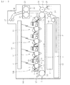
図1は、本発明の実施の一形態に係る画像形成装置としてのプリンタの概略構成図である。まず、図1を参照して、プリンタの全体構成及び動作について説明する。 FIG. 1 is a schematic configuration diagram of a printer as an image forming apparatus according to an embodiment of the present invention. First, the overall configuration and operation of the printer will be described with reference to FIG.
図1に示すように、プリンタの装置本体(画像形成装置本体)100の中央には、カラー画像の色分解成分に対応するイエロー(Y)、マゼンタ(M)、シアン(C)、ブラック(Bk)の異なる色の画像を形成する4つのプロセスユニット1Y,1M,1C,1Bkが設けられている。各プロセスユニット1Y,1M,1C,1Bkは、表面に静電潜像を担持する像担持体としての感光体2と、感光体2の表面を帯電させる帯電手段としての帯電ローラ3と、感光体2上の静電潜像にトナーを供給して現像する現像装置4と、感光体2の表面をクリーニングする感光体クリーニング装置5とを備える。
As shown in FIG. 1, at the center of the printer apparatus main body (image forming apparatus main body) 100, yellow (Y), magenta (M), cyan (C), black (Bk) corresponding to the color separation components of the color image. Are provided with four
なお、図1では、ブラックの画像を形成するプロセスユニット1Bkが備える感光体2、帯電ローラ3、現像装置4、感光体クリーニング装置5のみに符号を付しており、その他のプロセスユニット1M,1C,1Bkにおいては符号を省略している。
In FIG. 1, only the
現像装置4は、供給ローラ4aおよび現像ローラ4bを有する。現像装置4の上方に配置されたトナー補給容器21から現像装置4に移送されたトナーは、供給ローラ4aおよび現像ローラ4bの回転により感光体2の表面に供給される。各色トナーとしては、粒径6μm以下の小径でかつ高球形度の重合トナーを使用するのが好ましい。
The developing
感光体クリーニング装置5は、感光体2の表面をクリーニングするものであり、感光体2の回転方向に対してカウンター方向に当接するクリーニングブレード5aと、クリーニングブレード5aに除去されたトナーを移送する移送部材5bとを備えている。
The
図1において、各プロセスユニット1Y,1M,1C,1Bkの上方には、各感光体2の表面に静電潜像を形成する潜像形成手段としての露光装置6が配設されている。本実施形態の露光装置6は、光源、ポリゴンミラー、f−θレンズ、反射ミラー等を有し、画像データに基づいて各感光体2の表面へレーザー光を照射するように構成されているが、LEDアレイを用いたものであってもよい。
In FIG. 1, an exposure device 6 as a latent image forming means for forming an electrostatic latent image on the surface of each
一方、各プロセスユニット1Y,1M,1C,1Bkの下方には、記録媒体としての用紙にトナー画像を転写する転写装置7が配設されている。転写装置7は、中間転写体としての無端状のベルトから成る中間転写ベルト8を有する。この中間転写ベルト8は、駆動ローラ9、従動ローラ10、および一次転写ローラ11に掛け渡されている。駆動ローラ9が図の反時計回りに回転することによって、中間転写ベルト8は図の矢印に示す方向に周回走行(回転)するように構成されている。本実施形態において、駆動ローラ9は、後述する二次転写ニップにおいて、中間転写ベルト8を介して二次転写ローラ12と対向する対向部材としても機能する。
On the other hand, below each
4つの一次転写ローラ11は、4つの感光体2に対向した位置に配設されている。各一次転写ローラ11はそれぞれの位置で中間転写ベルト8の内周面を押圧しており、中間転写ベルト8の押圧された部分と各感光体2とが当接する箇所に一次転写ニップが形成されている。各一次転写ローラ11は、図示しない電源に接続されており、所定の直流電圧(DC)及び/又は交流電圧(AC)が一次転写ローラ11に印加されるようになっている。なお、本実施形態では、一次転写部材として、金属製のローラを用いているが、これ以外に、導電ブレードや導電スポンジローラ等を用いることも可能である。
The four
また、駆動ローラ9に対向した位置に、二次転写部材としての二次転写ローラ12が配設されている。この二次転写ローラ12は中間転写ベルト8の外周面を押圧しており、二次転写ローラ12と中間転写ベルト8とが当接する箇所に二次転写ニップが形成されている。二次転写ローラ12は、一次転写ローラ11と同様に、図示しない電源に接続されており、所定の直流電圧(DC)及び/又は交流電圧(AC)が二次転写ローラ12に印加されるようになっている。二次転写ローラ12は、金属製の芯金に導電性材料から成る弾性体を被覆して構成されている。二次転写ローラ12として、例えば、導電性ローラや電子導電タイプのローラ等を用いることが可能である。二次転写ローラ12は、中間転写ベルト8に対して接離可能な構成とせず、常時当接させておくのが望ましい。これによりコスト面で有利となる。
Further, a
中間転写ベルト8のうち、最上流のプロセスユニット1Yよりも上流側でかつ二次転写ニップよりも下流側の外周には、中間転写体クリーニング装置としてのベルトクリーニング装置13が配設されている。このベルトクリーニング装置13は、二次転写後の中間転写ベルト8上に残ったトナーを除去するもので、中間転写ベルト8の移動方向に対してカウンター方向に当接するクリーニングブレード13aと、クリーニングブレード13aに対向する金属製の対向ローラ13bと、コイル等からなる移送部材13cとを備えている。
A
また、中間転写ベルト8のうち、緩み側となるベルトの下流側にはセンサ22が配置される。図面では、最下流のプロセスユニット1Bkよりも下流側でかつ従動ローラ10と対向する領域にセンサ22を配置した場合を例示している。このセンサ22は、中間転写ベルト8上に転移したトナーの付着量を測定し、さらに各色トナー像の位置を測定するもので、正反射方式と拡散反射方式を組み合わせたものが使用される。このセンサ22からの情報に基づいて、画像濃度の調整や位置合わせ等が行われる。
A
転写装置7の下方には、トナー回収容器14が配設されている。このトナー回収容器14には、感光体クリーニング装置5の移送部材5bおよびベルトクリーニング装置13の移送部材13cで移送された廃トナーが収容される。
A
装置本体100の図の下部には、記録媒体としての用紙Pを収容する給紙トレイ15や、給紙トレイ15から用紙Pを給送する給紙ローラ16等が設けてある。ここで、用紙Pには、厚紙、はがき、封筒、普通紙、薄紙、塗工紙(コート紙やアート紙等)、トレーシングペーパ等が含まれる。また、記録媒体として、OHPシートやOHPフィルム等を用いることも可能である。
In the lower part of the figure of the apparatus
一方、装置本体100の上部には、用紙を外部へ排出するための一対の排紙ローラ17が配設されている。また、装置本体100の上面部には、装置外に排出された用紙をストックするための排紙トレイ18が設けてある。
On the other hand, a pair of
装置本体100内には、用紙Pを給紙トレイ15から二次転写ニップを通って排紙トレイ18へ搬送するための搬送路Rが配設されている。搬送路Rにおいて、二次転写ローラ12の位置よりも用紙搬送方向上流側には、搬送タイミングを計って二次転写ニップへ用紙を搬送するタイミングローラとしての一対のレジストローラ19が配設されている。一方、二次転写ローラ12の位置よりも用紙搬送方向下流側には、用紙に転写された未定着画像を定着するための定着装置20が配設されている。定着装置20は、図示しない加熱源を有する定着ローラ24と、定着ローラ24に加圧される加圧ローラ25とを備える。両ローラ24,25が当接した箇所では、定着ニップが形成されている。
In the apparatus
続いて、図1を参照して、本実施形態に係るプリンタの基本的動作について説明する。
印刷が開始されると、各プロセスユニット1Y,1M,1C,1Bkの各感光体2が図示しない駆動装置によって図の時計回りに回転駆動され、各感光体2の表面が帯電ローラ3によって所定の極性に一様に帯電される。図示しない読取装置やコンピュータ等からの画像情報に基づいて、露光装置6からの露光により、各感光体2の帯電面に静電潜像が形成される。このとき、各感光体2に露光する画像情報は所望のフルカラー画像をイエロー、マゼンタ、シアン及びブラックの色情報に分解した単色の画像情報である。このように感光体2上に形成された静電潜像に、各現像装置4からトナーが供給されることにより、静電潜像はトナー像として可視画像化(顕像化)される。
Next, a basic operation of the printer according to the present embodiment will be described with reference to FIG.
When printing is started, the
また、印刷が開始されると、中間転写ベルト8が図の矢印の方向に回転駆動される。さらに、各一次転写ローラ11に、トナーの帯電極性と逆極性の定電圧又は定電流制御された電圧が印加される。これにより、一次転写ニップにおいて転写電界が形成される。
When printing is started, the
その後、各感光体2の回転に伴い、感光体2上の各色のトナー画像が一次転写ニップに達したときに、一次転写ニップにおいて形成された上記転写電界によって、各感光体2上のトナー像が中間転写ベルト8上に順次重ね合わせて転写される。かくして、中間転写ベルト8の表面にフルカラーのトナー像が担持される。中間転写ベルト8に転写しきれなかった各感光体2上のトナーは、ベルトクリーニング装置5のクリーニングブレード5aによって表面から除去され、トナー回収容器14に移送される。また、各感光体2の表面が図示しない除電装置によって除電作用を受け、その表面電位が初期化されて次の画像形成に備えられる。
Thereafter, when each color toner image on the
また、給紙ローラ16が回転駆動を開始し、給紙トレイ15から用紙Pが搬送路Rに送り出される。搬送路Rに送り出された用紙Pは、レジストローラ19によってタイミングを計られて、二次転写ニップに送られる。このとき、二次転写ローラ12には、中間転写ベルト8上のトナー画像のトナー帯電極性と逆極性の転写電圧が印加されており、これにより、二次転写ニップに転写電界が形成されている。
Further, the
その後、中間転写ベルト8の回転に伴って、中間転写ベルト8上のトナー画像が二次転写ニップに達したときに、二次転写ニップにおいて形成された上記転写電界によって、中間転写ベルト8上のトナー画像が用紙P上に一括して転写される。また、用紙Pに転写しきれなかった中間転写ベルト8上のトナーは、ベルトクリーニング装置13のクリーニングブレード13aによって除去された後、トナー回収容器14に移送される。
Thereafter, when the toner image on the
その後、用紙Pは定着装置20へと搬送される。定着装置20では、用紙Pが、定着ローラ24と加圧ローラ25との間に形成された定着ニップを通過することにより、トナー画像が当該用紙Pに定着される。そして、用紙Pは、排紙ローラ17によって装置外へ排出され、排紙トレイ18上にストックされる。
Thereafter, the paper P is conveyed to the fixing
以上の説明は、用紙上にフルカラー画像を形成するときの画像形成動作であるが、4つのプロセスユニット1Y,1M,1C,1Bkのいずれか1つを使用して単色画像を形成したり、2つ又は3つのプロセスユニットを使用して、2色又は3色の画像を形成したりすることも可能である。
The above description is an image forming operation when a full-color image is formed on a sheet. A single-color image is formed using any one of the four
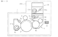
図2は、プロセスユニット1(1Y,1M,1C,1Bk)およびトナー補給容器21の概略構成を示す断面図である。以下では、同図に基づいて主としてトナー補給容器21および現像装置4の構成を説明する。
FIG. 2 is a cross-sectional view showing a schematic configuration of the process unit 1 (1Y, 1M, 1C, 1Bk) and the
トナー補給容器21は、例えばトナーカートリッジで構成されている。トナーカートリッジ21は、プロセスユニット1と独立して装置本体100に対して着脱可能であり、その内部には、攪拌部材としての攪拌パドル21aと、スクリューやコイルからなる搬送部材21bとが配置されている。また、トナーカートリッジ21には、装置本体100への装着時に現像装置4の内部空間につながるトナー補給口(図示省略)が設けられている。トナーカートリッジ21内に収容されたトナーは、その流動性保持のために攪拌パドル21aの回転で攪拌される。また、トナーは、搬送部材21bの回転により前述のトナー補給口に向けて搬送され、トナー補給口から現像装置4の内部に供給される。
The
搬送部材21bは、装置本体100に配置された駆動源に連結されている。搬送部材21bと駆動源の間はクラッチ等の公知の手段を介して結合状態と非結合状態とが切り替えられる。トナー補給量は駆動源の駆動時間で制御することができる。駆動源の駆動時間は、例えばトナーの流動性の変化(トナーの色や温度・湿度環境の変化)に応じて適宜制御される。
The
現像装置4は、上述の供給ローラ4aおよび現像ローラ4bの他に、輸送部材4c、アジテータ4d、および規制ブレード4eを有する。供給ローラ4a、現像ローラ4b、および規制ブレード4eには、それらに所定電圧を印加する電源が接続されている。現像装置4の内部では、アジテータ4dによりトナーが攪拌され、さらに輸送部材4cによってトナーが長手方向全域に移送される。トナーは、スポンジ材質からなる供給ローラ4aの回転でトナー担時体としての現像ローラ4bに移送され、さらに現像ローラ4bの回転で感光体2の表面に供給される。供給ローラ4aから現像ローラ4bに移送されたトナーは、規制ブレード4eにより均一な厚さにされてから感光体2の表面に供給される。
The developing
以上に説明したプロセスユニット1は、図2の破線で囲まれた領域中の各要素(感光体2、帯電ローラ3、現像装置4、および感光体クリーニング装置5)を一体に有するユニットである。従って、プロセスユニット1を装置本体100に着脱することで、これらの要素(2,3,4,5)が一括して装置本体100に対して着脱可能となる。以上の説明では、トナー補給容器21と現像装置4を近接させて配置し、トナー補給容器21から直接現像装置4内にトナーを補給する構成を例示したが、トナー補給容器21を現像装置4から離して配置し、トナー補給容器21から適宜の構成の補給経路を介して現像装置4にトナーを補給するようにした構成を採用することもできる。
The process unit 1 described above is a unit that integrally includes each element (the
プロセスユニット1には、製品情報や使用履歴情報等を格納するため、ICチップ等の記憶素子31が取り付けられている。また、装置本体100には、各プロセスユニット1の取り付け位置に、ICチップ31に格納された情報を読み取るための読み取り装置(図示省略)が設けられている。プロセスユニット1の装置本体100への装着は、このICチップ31に格納された情報を読み取り装置で読み取ることで認識することができる。かかる構成であれば、プロセスユニット1の装置本体100への着脱を検知するためのセンサを新たに設置する必要がなく、低コスト化を図ることができる。
A
ところで、このプロセスユニット1では、現像装置4からのトナー漏れ防止のため、現像ローラ4bの両端部にシール材(図示省略)を接触させている。プロセスユニット1を長期間使用すると、このシール材に摺接する現像ローラ4bの両端部が摩耗する。摩耗が進行すると、プロセスユニット1を装置本体100に着脱させた際に、その衝撃でトナーが漏れ、中間転写ベルト8上に落下するおそれがある(以下、この現象を「トナー落ち」と称する)。中間転写ベルト8に落下したトナーは、その後の印刷により二次転写ローラ12に転移し、用紙の裏汚れを発生させる要因となる。
By the way, in this process unit 1, in order to prevent toner leakage from the developing
この他、プロセスユニット1の着脱時のトナー落ちは、感光体2と感光体クリーニング装置5の境界部でも生じる。
In addition, toner drop when the process unit 1 is attached / detached also occurs at the boundary between the
以下、以上に述べた課題を解決する本発明の特徴的構成を説明する。
図1に示す本発明の画像形成装置には、二次転写ローラ12の表面をクリーニングするクリーニング手段30が設けられている。このクリーニング手段30は、二次転写ローラ12にトナーの帯電極性と同極性の電圧を印加することにより、二次転写ローラ12に付着したトナーを中間転写ベルト8に逆転写させて二次転写ローラ12をクリーニング(二次転写クリーニング)するものである。
Hereinafter, a characteristic configuration of the present invention that solves the above-described problems will be described.
The image forming apparatus of the present invention shown in FIG. 1 is provided with a cleaning means 30 for cleaning the surface of the
上記のとおり印刷中の二次転写ローラ12には、トナーの帯電極性と逆極性の転写電圧が印加されているが、二次転写クリーニング中は、二次転写ローラ12に印加される電圧が反転し、トナーの帯電極性と同極性の電圧が二次転写ローラ12に印加される。このように印加電圧を反転させるため、クリーニング手段30は、二次転写ローラ12への給電路を切り替える切り替え部26を有している。
As described above, a transfer voltage having a polarity opposite to the charging polarity of the toner is applied to the
このクリーニング手段30による二次転写クリーニングは、印刷中は行われず、印刷以外の段階で感光体2および中間転写ベルト8を回転駆動させる必要がある時に、これに付随する形で行われる。具体的には、
(1)主電源ONの操作があった時
(2)スリープ状態で立ち上げ操作があった時
(3)待機状態で立ち上げ操作があった時
(4)ジャム処理後に立ち上げ操作があった時
(5)強制終了後に立ち上げ操作があった時
から、画像形成装置がレディ状態となるまでの間にクリーニング手段30による二次転写クリーニングが行われる。また、この他にも、立ち上げ操作とは無関係に、印刷終了後のエンドシーケンスの実行時や、トナー像の位置合わせ、濃度調整、あるいは色合わせ等を行った際にもクリーニング手段30による二次転写クリーニングを行う場合がある。以上に述べた各二次転写クリーニングの実行時間は、予め対応する操作や事象ごとにデフォルトとして個別に設定されている
The secondary transfer cleaning by the cleaning means 30 is not performed during printing, but is performed in association with the
(1) When the main power is turned on (2) When the startup operation is performed in the sleep state (3) When the startup operation is performed in the standby state (4) The startup operation is performed after the jam processing (5) The secondary transfer cleaning is performed by the
ここで、上記(2)〜(5)の「立ち上げ操作」は、画像形成装置をレディ状態に立ち上げるための操作をいい、具体例として、外部機器からの画像信号の入力、外装カバーのクローズ動作、あるいは操作パネルの操作等を挙げることができる。上記(1)の主電源ONは、その操作自体が「立ち上げ操作」に該当する。 Here, the “start-up operation” in the above (2) to (5) refers to an operation for starting up the image forming apparatus in a ready state. As specific examples, input of an image signal from an external device, an exterior cover A closing operation or an operation of the operation panel can be exemplified. The operation itself of the main power ON of (1) corresponds to “start-up operation”.
なお、上記(2)の「スリープ状態」は画像形成エンジンOFFでかつ最低限必要なコントローラのみONとなっている状態(省電力モード)、上記(3)の待機状態は印刷終了直後であって、画像形成エンジンおよびコントローラが全てONとなっている状態を意味する。上記(5)の「強制終了」は、装置各部での異常検知(例えば定着装置20での過昇温)により印刷が強制終了された場合を意味する。上記(1)〜(3)は、前回の印刷が正常に行われた後の立ち上げ操作を表し、上記(4)および(5)は、何れも前回の印刷が異常終了した後の立ち上げ操作を意味する。 The “sleep state” in (2) is a state in which the image forming engine is OFF and only the necessary controller is ON (power saving mode), and the standby state in (3) is immediately after the end of printing. The image forming engine and the controller are all turned on. The “forced termination” in the above (5) means a case where printing is forcibly terminated due to abnormality detection in each part of the apparatus (for example, excessive temperature rise in the fixing device 20). The above (1) to (3) represent the start-up operation after the previous printing has been normally performed, and the above (4) and (5) are both the start-up after the previous printing has ended abnormally Means an operation.
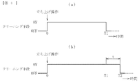
本発明では、上記の課題を解決するため、プロセスユニット1を装置本体100に装着した後、上記立ち上げ操作があった際にクリーニング手段30で二次転写クリーニングを行う一方、この時の二次転写クリーニングの実行時間T2(図3(b)参照)を、上記(1)〜(3)の立ち上げ操作(正常印刷完了後の立ち上げ操作)に対応してそれぞれデフォルトで設定された二次転写クリーニングの規定の実行時間T1(図3(a)参照)よりも所定時間tだけ延長している(T2>T1)。(1)〜(3)の各立ち上げ操作についてデフォルトで設定された二次転写クリーニングの実行時間が異なる場合、それらの中で最長の実行時間T1よりも実行時間T2が長くなるように延長時間tを定める。この延長時間tは画像形成装置に設けられた制御部が設定する。
In the present invention, in order to solve the above-described problem, after the process unit 1 is mounted on the apparatus
既存の画像形成装置でも、プロセスユニット1が装着された時は、これを主電源ONと認識し、(1)の立ち上げ操作に対応してデフォルトで設定された規定時間だけ二次転写クリーニングが行われている。これに対し、本発明は、上記のようにプロセスユニット1の装着があった時は、二次転写クリーニングの実行時間をこの規定時間よりも延長することを特徴とする。二次転写クリーニング中は、中間転写ベルト8の表面にトナーが付着していても、このトナーが二次転写ローラ12の表面に転着することはなく、かつ二次転写ニップを通過した中間転写ベルト8表面のトナーは、ベルトクリーニング装置13で回収・除去される。従って、本発明の構成であれば、次の印刷開始時には、中間転写ベルト8および二次転写ローラ12がクリーンな状態にすることができ、トナー落ちによる用紙の裏汚れを回避することが可能となる。
Even in the existing image forming apparatus, when the process unit 1 is mounted, it recognizes that the main power is ON, and the secondary transfer cleaning is performed for a specified time set by default corresponding to the start-up operation of (1). Has been done. On the other hand, the present invention is characterized in that when the process unit 1 is mounted as described above, the execution time of the secondary transfer cleaning is extended from the specified time. During the secondary transfer cleaning, even if toner adheres to the surface of the
近年ではファーストプリントタイムの短縮化が強く要請されており、この要請に応えるために、上記(1)〜(3)で述べた正常印刷終了後の立ち上げ操作からレディ状態になるまでの時間は短縮化(5秒未満)される傾向にある。そのため、既存の画像形成装置と同様に、上記(1)〜(3)の立ち上げ操作後、各立ち上げ操作に対応してデフォルトで設定された規定時間だけ二次転写クリーニングを行った場合でも、十分なクリーニング時間を確保することができず、用紙の裏汚れを防止することが困難となる。 In recent years, there has been a strong demand for shortening the first print time, and in order to meet this demand, the time from the start-up operation after the completion of normal printing described in (1) to (3) to the ready state is as follows. It tends to be shortened (less than 5 seconds). Therefore, similarly to the existing image forming apparatus, after the start-up operations (1) to (3) above, even when the secondary transfer cleaning is performed for a specified time set by default corresponding to each start-up operation. Therefore, it is difficult to secure a sufficient cleaning time, and it becomes difficult to prevent the back side of the paper from being stained.
これに対して、本発明の構成であれば、プロセスユニット1の着脱があった時だけ二次転写クリーニングの実行時間を延長されているため、上記(1)〜(3)の正常印刷完了後の立ち上げ操作に伴う二次転写クリーニングの実行時間は、それぞれデフォルトとして定められた規定時間となる。また、かかる制御の実現に際して、新たな部材を追加する必要はなく、シーケンスを変更するだけで対応することができる。従って、本発明によれば、ファーストプリントタイムの短縮化を図りつつ、用紙の裏汚れを低コストに防止することが可能となる。 On the other hand, in the configuration of the present invention, since the execution time of the secondary transfer cleaning is extended only when the process unit 1 is attached / detached, after the normal printing of the above (1) to (3) is completed. The execution time of the secondary transfer cleaning accompanying the start-up operation is a specified time determined as a default. Further, when realizing such control, it is not necessary to add a new member, and it can be dealt with only by changing the sequence. Therefore, according to the present invention, it is possible to prevent the backside contamination of the paper at a low cost while shortening the first print time.
なお、上記(4)および(5)の異常終了後の立ち上げ操作では、システムチェックのシーケンスを実行するのが通例であり、その処理にある程度の時間を要するため、立ち上げ操作からレディ状態となるまでに長時間(例えば15秒以上)を要する。従って、これらの立ち上げ操作に対応してデフォルトとして設定される二次転写クリーニングの実行時間も十分に長い時間とすることができる。そのため、前回の印刷が異常終了した後でプロセスユニット1を着脱し、その後の立ち上げ操作で二次転写クリーニングを行う場合には、二次転写クリーニングの実行時間を延長する必要はない。 In the startup operation after the abnormal end in (4) and (5) above, it is usual to execute a system check sequence. Since this processing requires a certain amount of time, the startup operation is changed to the ready state. It takes a long time (for example, 15 seconds or more). Therefore, the execution time of the secondary transfer cleaning set as a default corresponding to these start-up operations can also be set to a sufficiently long time. For this reason, when the process unit 1 is detached after the previous printing has ended abnormally and the secondary transfer cleaning is performed in the subsequent startup operation, it is not necessary to extend the execution time of the secondary transfer cleaning.
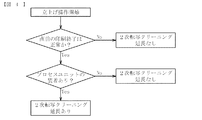
以下、本発明の第一実施形態を図4に基づいて説明する。図4は、二次転写クリーニングの実行時間を決定するための制御フローを示す図である。
同図に示すように、画像形成装置の立ち上げ操作が開始されると、直前の印刷が正常に完了したか否かが画像形成装置の制御部で判断される。Noの場合(異常印刷完了の場合)には、二次転写クリーニングの実行時間は延長されず、制御部からの指令でデフォルトとして設定された規定時間の二次転写クリーニングが実行される。YESの場合(正常印刷完了の場合)には、上述したICチップ31に格納された情報を読み取り装置で読み取ることにより、プロセスユニット1の装置本体100への装着が行われた否かが判断される。プロセスユニット1の装置本体100への装着が行われていた場合は、制御部からの指令で二次転写クリーニングの実行時間が延長される。一方、プロセスユニット1の装置本体100への装着が行われていない場合は、二次転写クリーニングの実行時間は延長されず、制御部からの指令でデフォルトとして設定された規定時間の二次転写クリーニングが実行される。
Hereinafter, a first embodiment of the present invention will be described with reference to FIG. FIG. 4 is a diagram showing a control flow for determining the execution time of the secondary transfer cleaning.
As shown in the figure, when the start-up operation of the image forming apparatus is started, the control unit of the image forming apparatus determines whether or not the previous printing has been normally completed. In the case of No (when abnormal printing is completed), the execution time of the secondary transfer cleaning is not extended, and the secondary transfer cleaning is performed for a specified time set as a default by a command from the control unit. In the case of YES (when normal printing is completed), it is determined whether or not the process unit 1 is attached to the apparatus
以上に述べた構成によれば、プロセスユニット1の装置本体100への装着が行われていた場合は、制御部からの指令で二次転写クリーニングの実行時間が延長される。これにより、プロセスユニット1の装置本体100への装着によりトナー漏れが生じ、中間転写ベルト8がトナーで汚染された場合でも、記録媒体の裏汚れを防止することができる。その一方で、正常印刷完了後の立ち上げ操作時に、プロセスユニット1の装置本体100への装着が行われていない場合には、二次転写クリーニングの実行時間を延長しないので、ファーストプリントタイムの短縮化を図ることができる。
According to the configuration described above, when the process unit 1 is attached to the apparatus
以上に述べた二次転写クリーニングの実行時間の延長は、プロセスユニット1の着脱が行われた際に常に行うことも考えられる。その一方で、プロセスユニット1の着脱時のトナー落ちは、装着したプロセスユニット1が新品であればほとんど生じないのが実情であり、このような場合にまで二次転写クリーニングの実行時間を延長すると経済的に不利となる。 The extension of the execution time of the secondary transfer cleaning described above may be always performed when the process unit 1 is attached or detached. On the other hand, the toner drop at the time of attaching / detaching the process unit 1 hardly occurs if the attached process unit 1 is new. In such a case, the execution time of the secondary transfer cleaning is extended. Economic disadvantage.
また、トナー落ちは、着脱したプロセスユニット1だけで生じるとは限らない。着脱の衝撃で装置本体が振動するため、その振動を受けた未着脱の他のプロセスユニット1でもトナー落ちが生じる。従ってプロセスユニット1の新旧判断を、着脱したプロセスユニット1だけで行うのは不十分であり、他のプロセスユニット1についても新旧判断を行うのが望ましい。 Further, toner dropping does not always occur only in the detached process unit 1. Since the apparatus main body vibrates due to the attachment / detachment impact, the toner is dropped also in other process units 1 that are not attached / detached due to the vibration. Therefore, it is not sufficient to make a new / old decision on the process unit 1 only with the detached process unit 1, and it is desirable to make a new / old decision on other process units 1 as well.
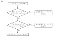
このような要請に着目した制御フローの一例を、第二実施形態として図5に示す。
先ず、プロセスユニット1の装着を認識した後、着脱したプロセスユニット1が旧品であるか否かを制御部で判断する。着脱したプロセスユニットが旧品であれば(Yes)、延長時間Aを選択して二次転写クリーニングを実行する。また、着脱したプロセスユニット1が新品であれば(No)、他のプロセスユニット1の状態を確認するフローに移行する。他のプロセスユニットが旧品であれば(Yes)、延長時間Bを選択して二次転写クリーニングを実行する。他のプロセスユニット1が新品であれば(No)、延長時間Cを選択して二次転写クリーニングを行う。
An example of a control flow focusing on such a request is shown in FIG. 5 as a second embodiment.
First, after recognizing the mounting of the process unit 1, the control unit determines whether or not the detached process unit 1 is an old product. If the detached process unit is an old product (Yes), the extension time A is selected and the secondary transfer cleaning is executed. If the detached process unit 1 is new (No), the process proceeds to a flow for checking the state of another process unit 1. If the other process unit is an old product (Yes), the extension time B is selected and the secondary transfer cleaning is executed. If the other process unit 1 is new (No), the extension time C is selected and the secondary transfer cleaning is performed.
本発明者らの検証により、シールS1からのトナー落ちは、プロセスユニット1の走行距離に関係することが判明している。これは、現像ローラ4bの端部ではトナー漏れ防止のためのシール材が接触しており、プロセスユニット1の走行距離が大きくなると、シール材との摺接により現像ローラ4bの端部が摩耗するためと考えられる。トナー落ちを生じる走行距離のしきい値は3000m以上であることも判明している。従って、図5に示す制御フローでのプロセスユニット1の新旧判断では、対象となるプロセスユニット1の走行距離LがL<3000[m]の関係である時に新品とし、3000[m]≦Lの関係である時に旧品とする。なお、プロセスユニット1の走行距離は、各プロセスユニット1に装着されたICチップ31に格納された情報から認識することができる。
According to the verification by the present inventors, it has been found that the toner drop from the seal S1 is related to the travel distance of the process unit 1. This is because the end portion of the developing
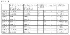
図6は、着脱したプロセスユニット1と、それ以外のプロセスユニット1とをそれぞれ新品および旧品として二次転写クリーニングの延長時間を変更し、その時のトナー落ちによる用紙の裏汚れを評価した結果を示すものである。 FIG. 6 shows the result of evaluating the backside contamination of the paper due to toner drop at the time when the extension time of the secondary transfer cleaning is changed with the detached process unit 1 and the other process units 1 as new and old products, respectively. It is shown.
同図中の実施例1および実施例2は、着脱したプロセスユニット1とそれ以外のプロセスユニット1を何れも新品とした場合である。但し、実施例1は各プロセスユニット1の走行距離LをL<1000[m]とし、実施例2の各プロセスユニットの走行距離(L<3000[m])よりも短くしている。実施例3は着脱したプロセスユニット1とそれ以外のプロセスユニット1を何れも旧品とした場合であり、実施例4は着脱したプロセスユニット1を新品とし、それ以外のプロセスユニット1を旧品とした場合である。 Example 1 and Example 2 in the figure are cases where both the detached process unit 1 and the other process units 1 are new. However, in the first embodiment, the travel distance L of each process unit 1 is set to L <1000 [m], which is shorter than the travel distance (L <3000 [m]) of each process unit of the second embodiment. The third embodiment is a case where the detached process unit 1 and the other process units 1 are both old products, and the fourth embodiment is that the detached process unit 1 is a new product, and the other process units 1 are old products. This is the case.
また、比較例1,2,3は各プロセスユニットの新旧状態を実施例3と共通にし、比較例4,5は各プロセスユニット1の新旧状態を実施例4と共通にしている。比較例1,2,3、および実施例3は二次転写クリーニングの延長時間tを異ならせている。同様に、比較例4,5および実施例4でも二次転写クリーニングの延長時間tを異ならせている。 In Comparative Examples 1, 2, and 3, the new and old states of the respective process units are made common to the third embodiment, and in Comparative Examples 4 and 5, the old and new states of the respective process units 1 are made common to the fourth embodiment. In Comparative Examples 1, 2, 3 and Example 3, the extension time t of the secondary transfer cleaning is varied. Similarly, in the comparative examples 4 and 5 and the example 4, the extension time t of the secondary transfer cleaning is varied.
図6の評価結果から以下の事実が明らかになった。
(a)着脱したプロセスユニット1およびそれ以外のプロセスユニット1が何れも新品である場合(実施例1,2)、二次転写クリーニングの延長時間が0でも用紙の裏汚れは発生しない。
(b)着脱したプロセスユニット1および他のプロセスユニット1が何れも旧品である場合(比較例1,2,3、実施例3)、用紙の裏汚れを完全に防止するためには、二次転写クリーニングの実行時間を15秒以上延長する必要がある。
(c)着脱したプロセスユニット1が新品で、それ以外のプロセスユニットが旧品である場合(比較例4,5、実施例4)、用紙の裏汚れを完全に防止するためには、二次転写クリーニングの実行時間を10秒以上延長する必要がある。
(d)着脱したプロセスユニット1および他のプロセスユニット1が何れも旧品である場合、着脱したプロセスユニット1が新品で、それ以外のプロセスユニットが旧品である場合よりも二次転写クリーニングの実行時間をさらに延長する必要がある。
(e)二次転写クリーニングの実行時間を5秒延長しても、程度の差はあれ用紙の裏汚れが発生する(比較例1〜5、実施例3,4)。
The following facts became clear from the evaluation results of FIG.
(A) When the detached process unit 1 and the other process units 1 are both new (Examples 1 and 2), the back side of the paper is not stained even if the extended time of the secondary transfer cleaning is zero.
(B) When the detached process unit 1 and the other process units 1 are both old products (Comparative Examples 1, 2, 3, and Example 3), It is necessary to extend the execution time of the next transfer cleaning by 15 seconds or more.
(C) When the detached process unit 1 is a new product and the other process units are old products (Comparative Examples 4 and 5 and Example 4), in order to completely prevent the paper from being stained, a secondary is used. It is necessary to extend the transfer cleaning execution time by 10 seconds or more.
(D) When both the detached process unit 1 and the other process unit 1 are old products, the secondary transfer cleaning is performed more than when the detached process unit 1 is a new product and the other process units are old products. The execution time needs to be further extended.
(E) Even if the execution time of the secondary transfer cleaning is extended by 5 seconds, the back side of the paper is somewhat stained (Comparative Examples 1 to 5, Examples 3 and 4).
以上の評価で使用した画像形成装置では、最上流のプロセスユニット1Yの一次転写ニップから二次転写ニップまでの距離が750mm程度、中間転写ベルト8の線速が150[mm/sec]になっている。この場合、中間転写ベルト8が最上流のプロセスユニット1Yの一次転写ニップから二次転写ニップに至るまでの所要時間は5秒となる。これと上記(e)の事実とから、最上流のプロセスユニット1Yから中間転写ベルト8上に落ちたトナーが二次転写ニップにある間は用紙の裏汚れを生じ、裏汚れを完全に防止するためには、少なくとも中間転写ベルト8上のトナーが二次転写ニップを越えるまで二次転写クリーニングを行う必要があることが理解できる。
In the image forming apparatus used in the above evaluation, the distance from the primary transfer nip to the secondary transfer nip of the most
以上に述べた評価試験の結果、およびその考察から、本発明の課題を解決するためには、上記の基本的制御に加えて、以下の制御の何れかを単独で、もしくは組み合わせて行うのが好ましい。 In order to solve the problems of the present invention based on the results of the evaluation test described above and the consideration thereof, in addition to the basic control described above, any of the following controls may be performed alone or in combination. preferable.
・プロセスユニット1装着後の二次転写ローラ12のクリーニングは、中間転写ベルト8のうち、最上流のプロセスユニットYの一次転写ニップを形成した部分が少なくとも二次転写ニップを通過するまで行う。これは、最上流のプロセスユニット1Yの一次転写ニップから二次転写ニップにいたるまでのベルトの周回距離をX[mm]とし、ベルト線速をV[m/sec]とした時、
T2>X/V …(式1)
の関係を満たすことを意味する。その一方で、ファーストプリントタイムの短縮化のため、正常印刷完了後の立ち上げ操作に対応してデフォルトで設定された二次転写クリーニングは、中間転写ベルト8の一次転写ニップを形成した部分が二次転写ニップに達するより前に完了させる。
Cleaning of the
T2> X / V (Formula 1)
Means satisfying the relationship. On the other hand, in order to shorten the first print time, the secondary transfer cleaning that is set by default in response to the start-up operation after the completion of normal printing is performed at the portion where the primary transfer nip of the
なお、トナーの色によって裏汚れが目立つ場合と目立たない場合がある。例えばイエローのプロセスユニット1だけでトナー落ちがあったとしても、裏汚れは目立ち難い。この場合、上記の式1は裏汚れが目立つ色、例えばブラックのプロセスユニット1Bkを基準に定めることも可能である。すなわち、プロセスユニット1装着後の二次転写ローラ12のクリーニングは、中間転写ベルト8のうち、ブラックのプロセスユニット1Bkの一次転写ニップを形成した部分が少なくとも二次転写ニップを通過するまで行う。
Depending on the color of the toner, the back stain may or may not be noticeable. For example, even if there is a toner drop only in the yellow process unit 1, the backside stains are hardly noticeable. In this case, the above formula 1 can be determined based on a process unit 1Bk of a color in which the back stain is conspicuous, for example, black. That is, the cleaning of the
・二次転写クリーニングの実行時間を延長するか否かは、装置本体100に装着されたプロセスユニット100の走行距離に基づいて判断する。
Whether to extend the execution time of the secondary transfer cleaning is determined based on the travel distance of the
・複数のプロセスユニット1を装置本体100に着脱可能とした構成では、複数のプロセスユニット1のうち、一部のプロセスユニットの装置本体100への装着後に、この一部のプロセスユニットおよび他のプロセスユニットの走行距離に応じて二次転写クリーニングの延長時間を定める。
In a configuration in which a plurality of process units 1 can be attached to and detached from the apparatus
・装置本体100に装着した一部のプロセスユニット1および他のプロセスユニット1が何れも新品である時には、二次転写クリーニングの延長時間を0にする。
When the part of the process units 1 attached to the apparatus
以上に述べたクリーニング手段30において、二次転写クリーニングの実行時間を延長する場合、デフォルトとして設定された規定時間T1および延長したクリーニング時間tの間は、二次転写ローラ12に印加する電圧を同極性にすることができる(トナーの帯電極性がマイナスであれば、クリーニング手段30による印加電圧も常時マイナスとする)。
In the cleaning means 30 described above, when the secondary transfer cleaning execution time is extended, the voltage applied to the
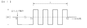
これ以外にも、図7に示すように、延長したクリーニング時間tの間は、二次転写ローラ12に印加する電圧の極性を交互に反転させることもできる。つまりプロセスユニット1が装置本体に装着された際には、二次転写ローラ12にトナーと同極性の電圧を規定時間T1だけ印加した後、トナーの帯電極性と同極性の電圧および逆極性の電圧を交互に印加するようクリーニング手段30を制御する。トナー中には、狙いの帯電極性のトナー粒子だけでなく、逆極性のトナー粒子が僅かに含まれるのが通例であるが、このように電圧極性を交互反転させれば、狙いとは逆極性のトナーも二次転写ローラ12の表面から確実に除去することができる。電圧極性の反転は、少なくとも二次転写ローラ12が1周するまで継続して行うのが好ましい。
In addition to this, as shown in FIG. 7, the polarity of the voltage applied to the
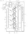
また、以上の説明では、クリーニング手段30として、二次転写ローラ12に電圧を印加するものを例示したが、図8に示すように、二次転写ローラ12と対向する駆動ローラ9に電圧を印加することもできる。この場合、駆動ローラ9には、トナーの帯電極性と逆極性の電圧が印加される。
In the above description, the
図8の構成においても、二次転写クリーニングに際しては、デフォルトとして設定された規定時間T1および延長したクリーニング時間t中に駆動ローラ9に印加する電圧を同じ極性にすることができる(トナーの帯電極性がマイナスであれば、印加電圧を常時プラスとする)。この他、図7と同様に、延長したクリーニング時間tにおいて電圧の極性を交互に反転させることもできる。つまり、プロセスユニット1が装置本体に装着された際には、駆動ローラ9にトナーと逆極性の電圧を規定時間T1だけ印加した後、トナーの帯電極性と同極性の電圧および逆極性の電圧を交互に印加するようクリーニング手段30を制御する。
Also in the configuration of FIG. 8, during the secondary transfer cleaning, the voltage applied to the
なお、本発明は上述の実施形態に限定されるものではなく、本発明の要旨を逸脱しない範囲で種々の変更を加え得ることは勿論である。例えば、本発明に係る画像形成装置は、図1に示すようなプリンタに限らず、複写機、ファクシミリ、あるいはこれらの複合機等とすることが可能である。 In addition, this invention is not limited to the above-mentioned embodiment, Of course, a various change can be added in the range which does not deviate from the summary of this invention. For example, the image forming apparatus according to the present invention is not limited to a printer as shown in FIG. 1, but may be a copying machine, a facsimile, or a complex machine thereof.
また、本実施形態では、図2に示すプロセスユニット1を装置本体100に着脱させる場合を例示したが、この他に公知の画像形成装置として、図2に二点鎖線で示すように、プロセスユニット1にさらにトナー補給容器21を一体化したオールインワンタイプ(AIOタイプ)と呼ばれるユニットを装置本体100に対して着脱するもの、現像装置4を主要構成とする現像ユニットを装置本体100に対して着脱するもの、さらには感光体2、帯電ローラ3、および感光体クリーニング装置5を主要構成とするユニットを装置本体100に対して着脱するもの(特許文献1参照)、がある。これら何れの構成の画像形成装置に対しても、本発明を適用することが可能である。すなわち、本発明は、感光体2と現像装置4のどちらか一方または双方を含むユニットを、装置本体100に着脱可能とした構成に適用することができる。
Further, in the present embodiment, the case where the process unit 1 shown in FIG. 2 is attached to and detached from the apparatus
また、以上の説明では、二次転写部材12としてローラを使用する場合を例示したが、二次転写部材はベルトで形成することもできる(二次転写ベルト)。
Moreover, although the case where a roller was used as the
また、以上の説明では、複数の感光体2を中間転写ベルト8の上方に設けることで、感光体2を中間転写ベルト8の上面に対向させた場合を例示したが、複数の感光体2を中間転写ベルト8の下方に設けることで、感光体2を中間ベルトの下面と対向させる構成にしてもよい。このような構成でも、プロセスユニット1の装着時にトナー漏れを生じて中間転写ベルト8がトナーで汚染させる可能性があるが、本発明を適用することにより、記録媒体の裏汚れを防止することができる。
In the above description, the case where the plurality of
1 プロセスユニット(ユニット)
2 感光体(像担持体)
4 現像装置
5 感光体クリーニング装置
6 露光装置
8 中間転写ベルト(中間転写体)
9 駆動ローラ(対向部材)
12 二次転写ローラ(二次転写部材)
13 ベルトクリーニング装置(中間転写体クリーニング装置)
26 切り替え部
30 クリーニング手段
31 ICチップ(記憶素子)
100 装置本体
1 Process unit (unit)
2 Photoconductor (image carrier)
4 Developing
9 Drive roller (opposing member)
12 Secondary transfer roller (secondary transfer member)
13 Belt cleaning device (intermediate transfer member cleaning device)
26
100 Main unit
Claims (12)
前記複数のユニットのうちのいずれかが装置本体へ装着された場合に、前記クリーニング手段で前記二次転写部材をクリーニングし、かつこのクリーニングの実行時間を、前記規定時間よりも延長し、
前記複数のユニットのうちのいずれかが装置本体へ装着された後の前記二次転写部材のクリーニングは、前記中間転写部材のうち、最上流の前記像担持体からトナー像が一次転写される部分が少なくとも二次転写ニップを通過するまで行うことを特徴とする画像形成装置。 An apparatus main body, a plurality of image bearing member for bearing a latent image, and a plurality of developing device for forming a toner image by supplying toner to each of the plurality of image bearing members, each of the plurality of image担時body A primary transfer nip is formed between the intermediate transfer body and the intermediate transfer body to which the toner images carried on the plurality of image carriers are respectively primary transferred, and a secondary transfer nip is formed between the intermediate transfer body and the intermediate transfer body. A secondary transfer member that secondarily transfers a toner image carried on the intermediate transfer member to a recording medium; and a cleaning unit that cleans the secondary transfer member, and any one of the plurality of image carriers , and one of the plurality of developing devices is detachable respectively either or both to a plurality of units apparatus body including a respective, before starting printing by raising operation after successful completion of printing ,Previous An image forming apparatus for cleaning a specified time the secondary transfer member cleaning means,
When any of the plurality of units is attached to the apparatus main body, the cleaning unit cleans the secondary transfer member, and the cleaning execution time is extended from the specified time ,
The cleaning of the secondary transfer member after any of the plurality of units is mounted on the apparatus main body is a portion of the intermediate transfer member where the toner image is primarily transferred from the most upstream image carrier. Is carried out until at least the secondary transfer nip passes .
前記クリーニング手段で、前記対向部材にトナーと逆極性の電圧を印加する請求項1に記載の画像形成装置。 A counter member facing the secondary transfer member via the intermediate transfer member in the secondary transfer nip;
The image forming apparatus according to claim 1, wherein the cleaning unit applies a voltage having a polarity opposite to that of the toner to the facing member.
前記複数のユニットのうちのいずれかが装置本体へ装着された際に、前記クリーニング手段で前記二次転写部材にトナーと同極性の電圧を前記規定時間印加した後、前記クリーニング手段で前記二次転写部材にトナーと同極性の電圧および逆極性の電圧を交互に印加する請求項1に記載の画像形成装置。 When cleaning the secondary transfer member by the cleaning unit for the specified time, a voltage having the same polarity as the toner is applied to the secondary transfer member by the cleaning unit,
When any of the plurality of units is mounted on the apparatus main body, the cleaning unit applies a voltage having the same polarity as the toner to the secondary transfer member for the specified time, and then the cleaning unit applies the secondary unit. The image forming apparatus according to claim 1, wherein a voltage having the same polarity as that of toner and a voltage having a reverse polarity are alternately applied to the transfer member.
前記クリーニング手段で前記二次転写部材を前記規定時間クリーニングする際に、前記クリーニング手段で前記対向部材にトナーと逆極性の電圧を印加し、
前記複数のユニットのうちのいずれかが装置本体へ装着された際に、前記クリーニング手段で前記対向部材にトナーと逆極性の電圧を前記規定時間印加した後、前記クリーニング手段で前記対向部材にトナーと同極性の電圧および逆極性の電圧を交互に印加する請求項1に記載の画像形成装置。 A counter member facing the secondary transfer member via the intermediate transfer member in the secondary transfer nip;
When the secondary transfer member is cleaned by the cleaning unit for the specified time, a voltage having a polarity opposite to that of the toner is applied to the counter member by the cleaning unit;
When any of the plurality of units is attached to the apparatus main body, the cleaning unit applies a voltage having a polarity opposite to that of the toner to the opposing member for the specified time, and then the cleaning unit applies the toner to the opposing member. The image forming apparatus according to claim 1, wherein the same polarity voltage and the opposite polarity voltage are alternately applied.
Priority Applications (3)
| Application Number | Priority Date | Filing Date | Title |
|---|---|---|---|
| JP2013119683A JP6160271B2 (en) | 2012-11-30 | 2013-06-06 | Image forming apparatus |
| US14/086,483 US9025994B2 (en) | 2012-11-30 | 2013-11-21 | Image forming apparatus |
| CN201310596633.9A CN103853020B (en) | 2012-11-30 | 2013-11-22 | Image processing system |
Applications Claiming Priority (3)
| Application Number | Priority Date | Filing Date | Title |
|---|---|---|---|
| JP2012263445 | 2012-11-30 | ||
| JP2012263445 | 2012-11-30 | ||
| JP2013119683A JP6160271B2 (en) | 2012-11-30 | 2013-06-06 | Image forming apparatus |
Publications (2)
| Publication Number | Publication Date |
|---|---|
| JP2014130316A JP2014130316A (en) | 2014-07-10 |
| JP6160271B2 true JP6160271B2 (en) | 2017-07-12 |
Family
ID=50825570
Family Applications (1)
| Application Number | Title | Priority Date | Filing Date |
|---|---|---|---|
| JP2013119683A Expired - Fee Related JP6160271B2 (en) | 2012-11-30 | 2013-06-06 | Image forming apparatus |
Country Status (3)
| Country | Link |
|---|---|
| US (1) | US9025994B2 (en) |
| JP (1) | JP6160271B2 (en) |
| CN (1) | CN103853020B (en) |
Families Citing this family (3)
| Publication number | Priority date | Publication date | Assignee | Title |
|---|---|---|---|---|
| JP2014112212A (en) * | 2012-11-01 | 2014-06-19 | Canon Inc | Image forming device |
| JP7742036B2 (en) * | 2021-09-15 | 2025-09-19 | 株式会社リコー | Image forming device |
| US11689679B1 (en) | 2022-01-28 | 2023-06-27 | Ricoh Company, Ltd. | Image forming apparatus |
Family Cites Families (26)
| Publication number | Priority date | Publication date | Assignee | Title |
|---|---|---|---|---|
| JP2983112B2 (en) * | 1992-08-31 | 1999-11-29 | 株式会社東芝 | Electrophotographic recording device |
| CA2105255C (en) * | 1992-08-31 | 1999-08-03 | Yoshiaki Okano | Electrophotographic apparatus that prevents toner from attaching to a contact member of a transfer device |
| JP3492858B2 (en) | 1996-07-31 | 2004-02-03 | 株式会社リコー | Developing device |
| JP2000132028A (en) | 1998-10-23 | 2000-05-12 | Canon Inc | Cleaning device, process cartridge and electrophotographic image forming device |
| US6931216B2 (en) * | 2002-06-21 | 2005-08-16 | Canon Kabushiki Kaisha | Image forming apparatus and the control method including a feature of detecting a remaining amount of a developer |
| JP2006259639A (en) | 2005-03-18 | 2006-09-28 | Ricoh Co Ltd | Image forming apparatus |
| JP4643324B2 (en) | 2005-03-18 | 2011-03-02 | 株式会社リコー | Image forming apparatus |
| JP4372716B2 (en) * | 2005-04-27 | 2009-11-25 | シャープ株式会社 | Transfer device and image forming apparatus |
| JP4628854B2 (en) | 2005-04-27 | 2011-02-09 | 株式会社リコー | Image forming apparatus |
| US7587159B2 (en) | 2006-09-15 | 2009-09-08 | Ricoh Company, Ltd. | Image forming method and apparatus including a relationship between secondary roller diameter and recording medium ingress position |
| JP5037917B2 (en) | 2006-12-04 | 2012-10-03 | 株式会社リコー | Image forming apparatus and image carrier unit |
| US7778573B2 (en) | 2006-12-26 | 2010-08-17 | Ricoh Company, Ltd. | Image forming apparatus and process cartridge |
| JP2008224955A (en) | 2007-03-12 | 2008-09-25 | Ricoh Co Ltd | Image forming apparatus and image forming method |
| JP5031451B2 (en) | 2007-06-18 | 2012-09-19 | 株式会社リコー | Transfer device and image forming apparatus |
| US8233823B2 (en) | 2007-07-13 | 2012-07-31 | Ricoh Company, Limited | Belt device and image forming apparatus |
| US7735634B2 (en) | 2007-07-13 | 2010-06-15 | Ricoh Company, Ltd. | Belt device and image forming apparatus |
| US8200105B2 (en) | 2007-08-31 | 2012-06-12 | Ricoh Company, Ltd. | First stage transfer bias of an image forming device |
| JP5082110B2 (en) | 2008-01-11 | 2012-11-28 | 株式会社リコー | Image forming apparatus and image forming method |
| JP5483146B2 (en) | 2008-02-18 | 2014-05-07 | 株式会社リコー | Image forming apparatus |
| JP5169458B2 (en) | 2008-05-09 | 2013-03-27 | 株式会社リコー | Image forming apparatus |
| JP5445896B2 (en) | 2008-06-26 | 2014-03-19 | 株式会社リコー | Image forming apparatus |
| JP5381462B2 (en) | 2009-07-29 | 2014-01-08 | 株式会社リコー | Image forming apparatus |
| JP2012027222A (en) * | 2010-07-23 | 2012-02-09 | Ricoh Co Ltd | Transfer device, image forming apparatus, program and recording medium |
| JP5743083B2 (en) * | 2011-05-26 | 2015-07-01 | コニカミノルタ株式会社 | Image forming apparatus |
| JP2013156351A (en) | 2012-01-27 | 2013-08-15 | Ricoh Co Ltd | Color image forming apparatus |
| JP6010850B2 (en) | 2012-04-05 | 2016-10-19 | 株式会社リコー | Image forming apparatus |
-
2013
- 2013-06-06 JP JP2013119683A patent/JP6160271B2/en not_active Expired - Fee Related
- 2013-11-21 US US14/086,483 patent/US9025994B2/en active Active
- 2013-11-22 CN CN201310596633.9A patent/CN103853020B/en not_active Expired - Fee Related
Also Published As
| Publication number | Publication date |
|---|---|
| CN103853020A (en) | 2014-06-11 |
| JP2014130316A (en) | 2014-07-10 |
| CN103853020B (en) | 2016-08-17 |
| US20140153955A1 (en) | 2014-06-05 |
| US9025994B2 (en) | 2015-05-05 |
Similar Documents
| Publication | Publication Date | Title |
|---|---|---|
| JP5074892B2 (en) | Image forming apparatus | |
| JP2011150311A (en) | Image forming apparatus | |
| JP6394936B2 (en) | Image forming apparatus and driving method of image forming apparatus | |
| JP2008225205A (en) | Image forming apparatus | |
| JP5335384B2 (en) | Image forming apparatus | |
| JP6160271B2 (en) | Image forming apparatus | |
| US8761617B2 (en) | Image forming apparatus | |
| US9703232B2 (en) | Image forming apparatus that performs a contacting operation for contacting a developing member with an image bearing member | |
| JP2006276511A (en) | Image forming apparatus | |
| JP5049559B2 (en) | Image forming apparatus | |
| JP6200834B2 (en) | Image forming apparatus | |
| US9239548B2 (en) | Image forming apparatus | |
| JP5793898B2 (en) | Image forming apparatus | |
| JP2011075712A (en) | Drum assembly and image forming apparatus including the drum assembly | |
| JP5633586B2 (en) | Image forming apparatus | |
| JP2013214031A (en) | Image formation device | |
| JP2006243109A (en) | Image forming apparatus | |
| JP6690394B2 (en) | Image forming device | |
| JP6171763B2 (en) | Image forming apparatus | |
| JP6717133B2 (en) | Cleaning device and image forming device | |
| JP6490568B2 (en) | Image forming apparatus | |
| JP2015219377A (en) | Belt cleaning device, intermediate transfer device, image forming device | |
| JP5381425B2 (en) | Image forming apparatus | |
| JP2009031552A (en) | Image forming apparatus | |
| JP2012128412A (en) | Image forming apparatus |
Legal Events
| Date | Code | Title | Description |
|---|---|---|---|
| A621 | Written request for application examination |
Free format text: JAPANESE INTERMEDIATE CODE: A621 Effective date: 20160527 |
|
| A131 | Notification of reasons for refusal |
Free format text: JAPANESE INTERMEDIATE CODE: A131 Effective date: 20170209 |
|
| A977 | Report on retrieval |
Free format text: JAPANESE INTERMEDIATE CODE: A971007 Effective date: 20170208 |
|
| A521 | Request for written amendment filed |
Free format text: JAPANESE INTERMEDIATE CODE: A523 Effective date: 20170403 |
|
| TRDD | Decision of grant or rejection written | ||
| A01 | Written decision to grant a patent or to grant a registration (utility model) |
Free format text: JAPANESE INTERMEDIATE CODE: A01 Effective date: 20170516 |
|
| A61 | First payment of annual fees (during grant procedure) |
Free format text: JAPANESE INTERMEDIATE CODE: A61 Effective date: 20170529 |
|
| R151 | Written notification of patent or utility model registration |
Ref document number: 6160271 Country of ref document: JP Free format text: JAPANESE INTERMEDIATE CODE: R151 |
|
| LAPS | Cancellation because of no payment of annual fees |