JP6158715B2 - Apparatus and method for treating obstruction in a body lumen - Google Patents
Apparatus and method for treating obstruction in a body lumen Download PDFInfo
- Publication number
- JP6158715B2 JP6158715B2 JP2013554659A JP2013554659A JP6158715B2 JP 6158715 B2 JP6158715 B2 JP 6158715B2 JP 2013554659 A JP2013554659 A JP 2013554659A JP 2013554659 A JP2013554659 A JP 2013554659A JP 6158715 B2 JP6158715 B2 JP 6158715B2
- Authority
- JP
- Japan
- Prior art keywords
- balloon
- outlet
- lumen
- distal end
- inner member
- Prior art date
- Legal status (The legal status is an assumption and is not a legal conclusion. Google has not performed a legal analysis and makes no representation as to the accuracy of the status listed.)
- Active
Links
Images


Classifications
-
- A—HUMAN NECESSITIES
- A61—MEDICAL OR VETERINARY SCIENCE; HYGIENE
- A61B—DIAGNOSIS; SURGERY; IDENTIFICATION
- A61B17/00—Surgical instruments, devices or methods, e.g. tourniquets
- A61B17/22—Implements for squeezing-off ulcers or the like on the inside of inner organs of the body; Implements for scraping-out cavities of body organs, e.g. bones; Calculus removers; Calculus smashing apparatus; Apparatus for removing obstructions in blood vessels, not otherwise provided for
- A61B17/22031—Gripping instruments, e.g. forceps, for removing or smashing calculi
- A61B17/22032—Gripping instruments, e.g. forceps, for removing or smashing calculi having inflatable gripping elements
-
- A—HUMAN NECESSITIES
- A61—MEDICAL OR VETERINARY SCIENCE; HYGIENE
- A61B—DIAGNOSIS; SURGERY; IDENTIFICATION
- A61B17/00—Surgical instruments, devices or methods, e.g. tourniquets
- A61B17/22—Implements for squeezing-off ulcers or the like on the inside of inner organs of the body; Implements for scraping-out cavities of body organs, e.g. bones; Calculus removers; Calculus smashing apparatus; Apparatus for removing obstructions in blood vessels, not otherwise provided for
- A61B17/221—Gripping devices in the form of loops or baskets for gripping calculi or similar types of obstructions
-
- A—HUMAN NECESSITIES
- A61—MEDICAL OR VETERINARY SCIENCE; HYGIENE
- A61B—DIAGNOSIS; SURGERY; IDENTIFICATION
- A61B17/00—Surgical instruments, devices or methods, e.g. tourniquets
- A61B17/32—Surgical cutting instruments
- A61B17/3205—Excision instruments
- A61B17/3207—Atherectomy devices working by cutting or abrading; Similar devices specially adapted for non-vascular obstructions
- A61B17/320725—Atherectomy devices working by cutting or abrading; Similar devices specially adapted for non-vascular obstructions with radially expandable cutting or abrading elements
-
- A—HUMAN NECESSITIES
- A61—MEDICAL OR VETERINARY SCIENCE; HYGIENE
- A61B—DIAGNOSIS; SURGERY; IDENTIFICATION
- A61B5/00—Measuring for diagnostic purposes; Identification of persons
- A61B5/68—Arrangements of detecting, measuring or recording means, e.g. sensors, in relation to patient
- A61B5/6846—Arrangements of detecting, measuring or recording means, e.g. sensors, in relation to patient specially adapted to be brought in contact with an internal body part, i.e. invasive
- A61B5/6847—Arrangements of detecting, measuring or recording means, e.g. sensors, in relation to patient specially adapted to be brought in contact with an internal body part, i.e. invasive mounted on an invasive device
- A61B5/6852—Catheters
- A61B5/6853—Catheters with a balloon
-
- A—HUMAN NECESSITIES
- A61—MEDICAL OR VETERINARY SCIENCE; HYGIENE
- A61F—FILTERS IMPLANTABLE INTO BLOOD VESSELS; PROSTHESES; DEVICES PROVIDING PATENCY TO, OR PREVENTING COLLAPSING OF, TUBULAR STRUCTURES OF THE BODY, e.g. STENTS; ORTHOPAEDIC, NURSING OR CONTRACEPTIVE DEVICES; FOMENTATION; TREATMENT OR PROTECTION OF EYES OR EARS; BANDAGES, DRESSINGS OR ABSORBENT PADS; FIRST-AID KITS
- A61F2/00—Filters implantable into blood vessels; Prostheses, i.e. artificial substitutes or replacements for parts of the body; Appliances for connecting them with the body; Devices providing patency to, or preventing collapsing of, tubular structures of the body, e.g. stents
- A61F2/95—Instruments specially adapted for placement or removal of stents or stent-grafts
- A61F2/958—Inflatable balloons for placing stents or stent-grafts
-
- A—HUMAN NECESSITIES
- A61—MEDICAL OR VETERINARY SCIENCE; HYGIENE
- A61M—DEVICES FOR INTRODUCING MEDIA INTO, OR ONTO, THE BODY; DEVICES FOR TRANSDUCING BODY MEDIA OR FOR TAKING MEDIA FROM THE BODY; DEVICES FOR PRODUCING OR ENDING SLEEP OR STUPOR
- A61M25/00—Catheters; Hollow probes
- A61M25/0097—Catheters; Hollow probes characterised by the hub
-
- A—HUMAN NECESSITIES
- A61—MEDICAL OR VETERINARY SCIENCE; HYGIENE
- A61M—DEVICES FOR INTRODUCING MEDIA INTO, OR ONTO, THE BODY; DEVICES FOR TRANSDUCING BODY MEDIA OR FOR TAKING MEDIA FROM THE BODY; DEVICES FOR PRODUCING OR ENDING SLEEP OR STUPOR
- A61M25/00—Catheters; Hollow probes
- A61M25/10—Balloon catheters
- A61M25/1002—Balloon catheters characterised by balloon shape
-
- A—HUMAN NECESSITIES
- A61—MEDICAL OR VETERINARY SCIENCE; HYGIENE
- A61M—DEVICES FOR INTRODUCING MEDIA INTO, OR ONTO, THE BODY; DEVICES FOR TRANSDUCING BODY MEDIA OR FOR TAKING MEDIA FROM THE BODY; DEVICES FOR PRODUCING OR ENDING SLEEP OR STUPOR
- A61M25/00—Catheters; Hollow probes
- A61M25/10—Balloon catheters
- A61M25/1011—Multiple balloon catheters
-
- A—HUMAN NECESSITIES
- A61—MEDICAL OR VETERINARY SCIENCE; HYGIENE
- A61M—DEVICES FOR INTRODUCING MEDIA INTO, OR ONTO, THE BODY; DEVICES FOR TRANSDUCING BODY MEDIA OR FOR TAKING MEDIA FROM THE BODY; DEVICES FOR PRODUCING OR ENDING SLEEP OR STUPOR
- A61M29/00—Dilators with or without means for introducing media, e.g. remedies
- A61M29/02—Dilators made of swellable material
-
- A—HUMAN NECESSITIES
- A61—MEDICAL OR VETERINARY SCIENCE; HYGIENE
- A61M—DEVICES FOR INTRODUCING MEDIA INTO, OR ONTO, THE BODY; DEVICES FOR TRANSDUCING BODY MEDIA OR FOR TAKING MEDIA FROM THE BODY; DEVICES FOR PRODUCING OR ENDING SLEEP OR STUPOR
- A61M5/00—Devices for bringing media into the body in a subcutaneous, intra-vascular or intramuscular way; Accessories therefor, e.g. filling or cleaning devices, arm-rests
- A61M5/007—Devices for bringing media into the body in a subcutaneous, intra-vascular or intramuscular way; Accessories therefor, e.g. filling or cleaning devices, arm-rests for contrast media
-
- A—HUMAN NECESSITIES
- A61—MEDICAL OR VETERINARY SCIENCE; HYGIENE
- A61B—DIAGNOSIS; SURGERY; IDENTIFICATION
- A61B17/00—Surgical instruments, devices or methods, e.g. tourniquets
- A61B17/32—Surgical cutting instruments
- A61B17/3205—Excision instruments
- A61B17/32056—Surgical snare instruments
-
- A—HUMAN NECESSITIES
- A61—MEDICAL OR VETERINARY SCIENCE; HYGIENE
- A61B—DIAGNOSIS; SURGERY; IDENTIFICATION
- A61B17/00—Surgical instruments, devices or methods, e.g. tourniquets
- A61B17/32—Surgical cutting instruments
- A61B17/3205—Excision instruments
- A61B17/3207—Atherectomy devices working by cutting or abrading; Similar devices specially adapted for non-vascular obstructions
-
- A—HUMAN NECESSITIES
- A61—MEDICAL OR VETERINARY SCIENCE; HYGIENE
- A61B—DIAGNOSIS; SURGERY; IDENTIFICATION
- A61B17/00—Surgical instruments, devices or methods, e.g. tourniquets
- A61B17/22—Implements for squeezing-off ulcers or the like on the inside of inner organs of the body; Implements for scraping-out cavities of body organs, e.g. bones; Calculus removers; Calculus smashing apparatus; Apparatus for removing obstructions in blood vessels, not otherwise provided for
- A61B17/22031—Gripping instruments, e.g. forceps, for removing or smashing calculi
- A61B2017/22034—Gripping instruments, e.g. forceps, for removing or smashing calculi for gripping the obstruction or the tissue part from inside
-
- A—HUMAN NECESSITIES
- A61—MEDICAL OR VETERINARY SCIENCE; HYGIENE
- A61B—DIAGNOSIS; SURGERY; IDENTIFICATION
- A61B17/00—Surgical instruments, devices or methods, e.g. tourniquets
- A61B17/22—Implements for squeezing-off ulcers or the like on the inside of inner organs of the body; Implements for scraping-out cavities of body organs, e.g. bones; Calculus removers; Calculus smashing apparatus; Apparatus for removing obstructions in blood vessels, not otherwise provided for
- A61B2017/22051—Implements for squeezing-off ulcers or the like on the inside of inner organs of the body; Implements for scraping-out cavities of body organs, e.g. bones; Calculus removers; Calculus smashing apparatus; Apparatus for removing obstructions in blood vessels, not otherwise provided for with an inflatable part, e.g. balloon, for positioning, blocking, or immobilisation
- A61B2017/22061—Implements for squeezing-off ulcers or the like on the inside of inner organs of the body; Implements for scraping-out cavities of body organs, e.g. bones; Calculus removers; Calculus smashing apparatus; Apparatus for removing obstructions in blood vessels, not otherwise provided for with an inflatable part, e.g. balloon, for positioning, blocking, or immobilisation for spreading elements apart
-
- A—HUMAN NECESSITIES
- A61—MEDICAL OR VETERINARY SCIENCE; HYGIENE
- A61B—DIAGNOSIS; SURGERY; IDENTIFICATION
- A61B17/00—Surgical instruments, devices or methods, e.g. tourniquets
- A61B17/22—Implements for squeezing-off ulcers or the like on the inside of inner organs of the body; Implements for scraping-out cavities of body organs, e.g. bones; Calculus removers; Calculus smashing apparatus; Apparatus for removing obstructions in blood vessels, not otherwise provided for
- A61B2017/22082—Implements for squeezing-off ulcers or the like on the inside of inner organs of the body; Implements for scraping-out cavities of body organs, e.g. bones; Calculus removers; Calculus smashing apparatus; Apparatus for removing obstructions in blood vessels, not otherwise provided for after introduction of a substance
- A61B2017/22084—Implements for squeezing-off ulcers or the like on the inside of inner organs of the body; Implements for scraping-out cavities of body organs, e.g. bones; Calculus removers; Calculus smashing apparatus; Apparatus for removing obstructions in blood vessels, not otherwise provided for after introduction of a substance stone- or thrombus-dissolving
-
- A—HUMAN NECESSITIES
- A61—MEDICAL OR VETERINARY SCIENCE; HYGIENE
- A61B—DIAGNOSIS; SURGERY; IDENTIFICATION
- A61B17/00—Surgical instruments, devices or methods, e.g. tourniquets
- A61B17/22—Implements for squeezing-off ulcers or the like on the inside of inner organs of the body; Implements for scraping-out cavities of body organs, e.g. bones; Calculus removers; Calculus smashing apparatus; Apparatus for removing obstructions in blood vessels, not otherwise provided for
- A61B17/221—Gripping devices in the form of loops or baskets for gripping calculi or similar types of obstructions
- A61B2017/2212—Gripping devices in the form of loops or baskets for gripping calculi or similar types of obstructions having a closed distal end, e.g. a loop
-
- A—HUMAN NECESSITIES
- A61—MEDICAL OR VETERINARY SCIENCE; HYGIENE
- A61B—DIAGNOSIS; SURGERY; IDENTIFICATION
- A61B17/00—Surgical instruments, devices or methods, e.g. tourniquets
- A61B17/22—Implements for squeezing-off ulcers or the like on the inside of inner organs of the body; Implements for scraping-out cavities of body organs, e.g. bones; Calculus removers; Calculus smashing apparatus; Apparatus for removing obstructions in blood vessels, not otherwise provided for
- A61B17/221—Gripping devices in the form of loops or baskets for gripping calculi or similar types of obstructions
- A61B2017/2215—Gripping devices in the form of loops or baskets for gripping calculi or similar types of obstructions having an open distal end
-
- A—HUMAN NECESSITIES
- A61—MEDICAL OR VETERINARY SCIENCE; HYGIENE
- A61M—DEVICES FOR INTRODUCING MEDIA INTO, OR ONTO, THE BODY; DEVICES FOR TRANSDUCING BODY MEDIA OR FOR TAKING MEDIA FROM THE BODY; DEVICES FOR PRODUCING OR ENDING SLEEP OR STUPOR
- A61M25/00—Catheters; Hollow probes
- A61M2025/0008—Catheters; Hollow probes having visible markings on its surface, i.e. visible to the naked eye, for any purpose, e.g. insertion depth markers, rotational markers or identification of type
-
- A—HUMAN NECESSITIES
- A61—MEDICAL OR VETERINARY SCIENCE; HYGIENE
- A61M—DEVICES FOR INTRODUCING MEDIA INTO, OR ONTO, THE BODY; DEVICES FOR TRANSDUCING BODY MEDIA OR FOR TAKING MEDIA FROM THE BODY; DEVICES FOR PRODUCING OR ENDING SLEEP OR STUPOR
- A61M25/00—Catheters; Hollow probes
- A61M25/10—Balloon catheters
- A61M2025/1043—Balloon catheters with special features or adapted for special applications
- A61M2025/105—Balloon catheters with special features or adapted for special applications having a balloon suitable for drug delivery, e.g. by using holes for delivery, drug coating or membranes
-
- A—HUMAN NECESSITIES
- A61—MEDICAL OR VETERINARY SCIENCE; HYGIENE
- A61M—DEVICES FOR INTRODUCING MEDIA INTO, OR ONTO, THE BODY; DEVICES FOR TRANSDUCING BODY MEDIA OR FOR TAKING MEDIA FROM THE BODY; DEVICES FOR PRODUCING OR ENDING SLEEP OR STUPOR
- A61M25/00—Catheters; Hollow probes
- A61M25/10—Balloon catheters
- A61M2025/1043—Balloon catheters with special features or adapted for special applications
- A61M2025/1068—Balloon catheters with special features or adapted for special applications having means for varying the length or diameter of the deployed balloon, this variations could be caused by excess pressure
-
- A—HUMAN NECESSITIES
- A61—MEDICAL OR VETERINARY SCIENCE; HYGIENE
- A61M—DEVICES FOR INTRODUCING MEDIA INTO, OR ONTO, THE BODY; DEVICES FOR TRANSDUCING BODY MEDIA OR FOR TAKING MEDIA FROM THE BODY; DEVICES FOR PRODUCING OR ENDING SLEEP OR STUPOR
- A61M25/00—Catheters; Hollow probes
- A61M25/10—Balloon catheters
- A61M2025/1043—Balloon catheters with special features or adapted for special applications
- A61M2025/1077—Balloon catheters with special features or adapted for special applications having a system for expelling the air out of the balloon before inflation and use
-
- A—HUMAN NECESSITIES
- A61—MEDICAL OR VETERINARY SCIENCE; HYGIENE
- A61M—DEVICES FOR INTRODUCING MEDIA INTO, OR ONTO, THE BODY; DEVICES FOR TRANSDUCING BODY MEDIA OR FOR TAKING MEDIA FROM THE BODY; DEVICES FOR PRODUCING OR ENDING SLEEP OR STUPOR
- A61M25/00—Catheters; Hollow probes
- A61M25/10—Balloon catheters
- A61M2025/1043—Balloon catheters with special features or adapted for special applications
- A61M2025/1084—Balloon catheters with special features or adapted for special applications having features for increasing the shape stability, the reproducibility or for limiting expansion, e.g. containments, wrapped around fibres, yarns or strands
-
- A—HUMAN NECESSITIES
- A61—MEDICAL OR VETERINARY SCIENCE; HYGIENE
- A61M—DEVICES FOR INTRODUCING MEDIA INTO, OR ONTO, THE BODY; DEVICES FOR TRANSDUCING BODY MEDIA OR FOR TAKING MEDIA FROM THE BODY; DEVICES FOR PRODUCING OR ENDING SLEEP OR STUPOR
- A61M25/00—Catheters; Hollow probes
- A61M25/10—Balloon catheters
- A61M2025/1043—Balloon catheters with special features or adapted for special applications
- A61M2025/1086—Balloon catheters with special features or adapted for special applications having a special balloon surface topography, e.g. pores, protuberances, spikes or grooves
-
- A—HUMAN NECESSITIES
- A61—MEDICAL OR VETERINARY SCIENCE; HYGIENE
- A61M—DEVICES FOR INTRODUCING MEDIA INTO, OR ONTO, THE BODY; DEVICES FOR TRANSDUCING BODY MEDIA OR FOR TAKING MEDIA FROM THE BODY; DEVICES FOR PRODUCING OR ENDING SLEEP OR STUPOR
- A61M25/00—Catheters; Hollow probes
- A61M25/10—Balloon catheters
- A61M2025/1043—Balloon catheters with special features or adapted for special applications
- A61M2025/109—Balloon catheters with special features or adapted for special applications having balloons for removing solid matters, e.g. by grasping or scraping plaque, thrombus or other matters that obstruct the flow
-
- A—HUMAN NECESSITIES
- A61—MEDICAL OR VETERINARY SCIENCE; HYGIENE
- A61M—DEVICES FOR INTRODUCING MEDIA INTO, OR ONTO, THE BODY; DEVICES FOR TRANSDUCING BODY MEDIA OR FOR TAKING MEDIA FROM THE BODY; DEVICES FOR PRODUCING OR ENDING SLEEP OR STUPOR
- A61M25/00—Catheters; Hollow probes
- A61M25/0067—Catheters; Hollow probes characterised by the distal end, e.g. tips
- A61M25/0074—Dynamic characteristics of the catheter tip, e.g. openable, closable, expandable or deformable
- A61M25/0075—Valve means
-
- A—HUMAN NECESSITIES
- A61—MEDICAL OR VETERINARY SCIENCE; HYGIENE
- A61M—DEVICES FOR INTRODUCING MEDIA INTO, OR ONTO, THE BODY; DEVICES FOR TRANSDUCING BODY MEDIA OR FOR TAKING MEDIA FROM THE BODY; DEVICES FOR PRODUCING OR ENDING SLEEP OR STUPOR
- A61M25/00—Catheters; Hollow probes
- A61M25/10—Balloon catheters
- A61M25/1018—Balloon inflating or inflation-control devices
- A61M25/10184—Means for controlling or monitoring inflation or deflation
- A61M25/10185—Valves
Description
本発明は、概して、患者の身体管腔内で手技を行うために、例えば、管状移植片、動静脈瘻、血管等内の閉塞性物質を除去または処置するための装置に関する。より具体的には、本発明は、医療手技、例えば、身体管腔内の血栓または他の閉塞性物質を除去するか、または別様に捕捉すること、身体管腔を拡張させること、および/または補綴物を送達することを伴う手技中に、流体を身体管腔に注入するための装置、例えば、カテーテルと、そのような装置を作製および使用するための方法に関する。 The present invention generally relates to an apparatus for removing or treating occlusive material within, for example, a tubular graft, arteriovenous fistula, blood vessel, etc., for performing a procedure within a body lumen of a patient. More specifically, the present invention relates to medical procedures such as removing or otherwise capturing a thrombus or other occlusive material within a body lumen, dilating the body lumen, and / or Or relates to a device for injecting fluid into a body lumen, for example a catheter, and a method for making and using such a device during a procedure involving delivery of a prosthesis.
患者の血管系内の血管または他の身体管腔内の流動は、種々の理由により、収縮され、または最終的に中断され得る。例えば、血管は、炎症および/または細胞増殖により、次第に狭くなり得る。加えて、そのような狭小化または血管内の他の流動問題により血栓が形成し得る。 Flow in blood vessels or other body lumens in the patient's vasculature can be deflated or eventually interrupted for a variety of reasons. For example, blood vessels can become increasingly narrow due to inflammation and / or cell proliferation. In addition, thrombus can form due to such narrowing or other flow problems within the blood vessels.
例えば、動静脈移植片が、例えば、透析治療を促進するために腎不全を患っている患者の腕に埋め込まれてもよい。そのような移植片は、例えば、隣接動脈と静脈または他の血管との間の組織を通して、患者の身体に直接形成される瘻孔であってもよく、2本の血管の間に埋め込まれる異種移植片であってもよく、または合成移植片であってもよい。そのような移植片は、炎症、血栓形成等により、限定された寿命しか持たない。いったん移植片が十分に閉塞されるか、または別様に劣化すると、新しい移植片が、後続の処置のための新しい場所に埋め込まれなければならない。 For example, an arteriovenous graft may be implanted in the arm of a patient suffering from renal failure, for example, to facilitate dialysis treatment. Such a graft may be, for example, a fistula formed directly in a patient's body through tissue between adjacent arteries and veins or other blood vessels, which may be implanted between two blood vessels. It may be a piece or a synthetic graft. Such grafts have a limited lifetime due to inflammation, thrombus formation, and the like. Once the implant is fully occluded or otherwise deteriorated, a new implant must be implanted at a new location for subsequent procedures.
したがって、動静脈移植片、血管、または他の身体管腔から物質を除去し、および/または身体管腔を別様に処置するための装置および方法が有用となるであろう。 Thus, devices and methods for removing material from arteriovenous grafts, blood vessels, or other body lumens and / or otherwise treating body lumens would be useful.
本発明は、患者の身体管腔、例えば、管状移植片、動静脈瘻、血管等内で手技を行うための装置を対象とする。より具体的には、本発明は、医療手技中に流体を身体管腔に注入するため、および/または身体管腔内の血栓または他の閉塞性物質を除去するか、または別様に捕捉するための装置および方法、例えば、閉塞性または他の物質を除去すること、身体管腔を拡張させること、身体管腔内で補綴物を送達すること、および/または他の手技を伴う手技を対象とする。 The present invention is directed to an apparatus for performing a procedure in a patient's body lumen, such as a tubular graft, arteriovenous fistula, blood vessel, or the like. More specifically, the present invention is for injecting fluid into a body lumen during a medical procedure and / or removing or otherwise capturing a thrombus or other occlusive material within the body lumen. For devices and methods for removing, for example, occlusive or other substances, dilating body lumens, delivering prosthetics within body lumens, and / or procedures involving other procedures And
第1の実施形態によれば、種々の機能を果たすように異なるモードにおいて動作可能であり、例えば、おそらく手技中のデバイス交換の数を低減させる、身体管腔内で手技を行うための装置が提供される。例えば、本装置は、近位端と、身体管腔の中へ導入するためにサイズ決定される遠位端と、その間に延在する管腔と、管腔と連通する内部を有する遠位端上のバルーンとを含む、シャフトを含んでもよい。本装置はまた、管腔と連通する出口を選択的に開放または閉鎖する、シャフトの遠位端上の弁を含んでもよい。弁が開いていると、管腔に導入される流体は、遠位端に隣接する身体管腔の中へと出口から退出してもよい。弁が閉鎖していると、管腔に導入される流体は、例えば、身体管腔内の閉塞を拡張させるように、身体管腔内の血栓または他の物質を除去するように、遠位端上で担持される補綴物を送達するように、遠位端上で担持される薬剤または他の作用物質を送達するように等のために、収縮状態から拡張状態までバルーンを拡張してもよい。 According to the first embodiment, there is provided an apparatus for performing a procedure in a body lumen that is operable in different modes to perform various functions, for example, possibly reducing the number of device exchanges during the procedure. Provided. For example, the device includes a proximal end, a distal end sized for introduction into a body lumen, a lumen extending therebetween, and a distal end having an interior in communication with the lumen A shaft may be included, including an upper balloon. The device may also include a valve on the distal end of the shaft that selectively opens or closes the outlet communicating with the lumen. When the valve is open, fluid introduced into the lumen may exit the outlet into the body lumen adjacent to the distal end. When the valve is closed, the fluid introduced into the lumen, for example, removes a thrombus or other substance in the body lumen so as to dilate the occlusion in the body lumen. The balloon may be expanded from a contracted state to an expanded state, such as to deliver a drug or other agent carried on the distal end, such as to deliver a prosthesis carried on the top. .
別の実施形態によれば、近位端、遠位端、ならびに近位および遠位端の間に延在する第1の管腔を含む、細長い管状外側部材と、管状部材の遠位端に固定される近位端、および出口を含む遠位端を含む、拡張可能バルーンであって、第1の管腔およびバルーン出口と連通する内部を含む、バルーンとを含む、身体管腔を処置するための装置が提供される。管状部材の近位端に隣接する近位端と、バルーンの中へ、バルーンを通って、および/またはバルーンを越えて延在する遠位端とを含む、細長い内側部材が、第1の管腔内で摺動可能に配置される。バルーンおよび内側部材は、バルーン出口を選択的に開閉するための弁を提供する、協働特徴を含んでもよい。例えば、弁は、流体流動から出口を実質的に密閉するよう、バルーンの遠位端と係合させられるようにサイズ決定される内側部材の遠位端上の密閉部材を含んでもよい。 According to another embodiment, an elongated tubular outer member including a proximal end, a distal end, and a first lumen extending between the proximal and distal ends, and a distal end of the tubular member Treating a body lumen, including a balloon, including an expandable balloon including a proximal end fixed and a distal end including an outlet, the first lumen and an interior in communication with the balloon outlet. An apparatus is provided for. An elongate inner member comprising a proximal end adjacent the proximal end of the tubular member and a distal end extending into, through, and / or beyond the balloon is a first tube. It is slidably arranged in the cavity. The balloon and inner member may include cooperating features that provide a valve for selectively opening and closing the balloon outlet. For example, the valve may include a sealing member on the distal end of the inner member that is sized to be engaged with the distal end of the balloon to substantially seal the outlet from fluid flow.
内側部材は、第1の管腔を通して導入される流体バルーン内部を通過してバルーン出口から出るように、密閉部材がバルーンの遠位端から離間される第1の位置と、第1の管腔を通して導入される流体がバルーン内部に進入してバルーンを拡張するように、密閉部材がバルーン出口を実質的に密閉する第2の位置との間で移動可能であり得る。 A first location where the sealing member is spaced from the distal end of the balloon such that the inner member passes through the fluid balloon introduced through the first lumen and exits the balloon outlet; The sealing member may be movable between a second position that substantially seals the balloon outlet such that fluid introduced therethrough enters the interior of the balloon and expands the balloon.
随意に、内側部材は、第1および第2の位置の一方に向かって付勢されてもよいが、第1および第2の位置の他方に選択的に誘導されてもよい。例えば、張力部材が、バルーン内部内に提供され、例えば、バルーンと内側部材との間に連結されてもよい。一実施形態では、密閉部材がバルーン内部内に配置される場合、張力部材は、例えば、密閉部材が弁を開放するように作動させられたときに、バルーンの遠位端が近位に移動することを防止するように、密閉部材から離してバルーンの遠位端を遠位に付勢してもよい。例えば、張力部材は、内側部材が弁を閉鎖するように遠位に誘導されたときに圧縮され、および内側部材が弁を開放するように近位に誘導されたときに部分的に弛緩することが許可され得る、圧縮バネであってもよい。 Optionally, the inner member may be biased toward one of the first and second positions, but may be selectively guided to the other of the first and second positions. For example, a tension member may be provided within the balloon interior and connected, for example, between the balloon and the inner member. In one embodiment, when the sealing member is disposed within the balloon interior, the tension member moves proximally at the distal end of the balloon, for example when the sealing member is actuated to open the valve. To prevent this, the distal end of the balloon may be biased distally away from the sealing member. For example, the tension member may be compressed when the inner member is guided distally to close the valve and partially relaxed when the inner member is guided proximally to open the valve. May be a compression spring.
別の実施形態では、密閉部材がバルーン出口を越えて遠位に配置される場合、張力部材は、例えば、密閉部材をバルーンの遠位端と係合させて出口を実質的に密閉するように、バルーンの遠位端を遠位に付勢してもよい。例えば、張力部材は、バルーン上のバネ停止部と内側部材上のカラーまたは他の取付部材との間に連結されてもよい。内側部材が出口を開放するように遠位に前進させられるとき、張力部材は、バネ停止部とカラーとの間で圧縮されてもよい。内側部材が出口を閉鎖するように解放されるか、または誘導されるとき、張力部材は、バルーンの遠位端が、近位に移動しない、および/または密閉部材で出口を再密閉するか、または再密閉を強化するように自動的に内側部材を近位に誘導し得ることを確実にしてもよい。 In another embodiment, when the sealing member is disposed distally beyond the balloon outlet, the tension member may, for example, engage the sealing member with the distal end of the balloon to substantially seal the outlet. The distal end of the balloon may be biased distally. For example, the tension member may be coupled between a spring stop on the balloon and a collar or other attachment member on the inner member. When the inner member is advanced distally to open the outlet, the tension member may be compressed between the spring stop and the collar. When the inner member is released or guided to close the outlet, the tension member may not cause the distal end of the balloon to move proximally and / or reseal the outlet with a sealing member, Or it may be ensured that the inner member can be automatically guided proximally to enhance reseal.
所望であれば、バルーンの遠位端は、出口を密閉および/または開放することを促進するように成形および/または構成される、遠位先端を含んでもよい。例えば、一実施形態では、密閉部材は、テーパ状近位端を含んでもよく、遠位先端は、密閉部材のテーパ状近位端が少なくとも部分的に広口遠位先端の中に着座され得るように、バルーンから外向きに広げられてもよい。そのような実施形態は、出口の密閉を強化し得る、密閉部材と遠位端との間の表面接触を増加させてもよい。加えて、または代替として、広口遠位先端は、密閉部材が出口から離れるように誘導されたときに出口の自由面積を最大限化してもよい。 If desired, the distal end of the balloon may include a distal tip that is shaped and / or configured to facilitate sealing and / or opening the outlet. For example, in one embodiment, the sealing member may include a tapered proximal end and the distal tip is such that the tapered proximal end of the sealing member can be seated at least partially within the wide-mouthed distal tip. Alternatively, it may be spread outward from the balloon. Such an embodiment may increase surface contact between the sealing member and the distal end that may enhance the sealing of the outlet. In addition or alternatively, the wide-mouthed distal tip may maximize the free area of the outlet when the sealing member is guided away from the outlet.
別の実施形態では、例えば、密閉部材とバルーンの遠位端との間の表面接触を増加させて、出口の密閉を強化するように、弾性的に拡張可能である遠位先端が提供されてもよい。例えば、遠位先端は、密閉部材が遠位先端の中へ近位に誘導されたとき、遠位先端が拡張して密閉部材の形状に一致し得るように、バルーンの遠位端と比較して、相対的に薄くてもよい。密閉部材が出口を開放するように遠位に誘導されたとき、遠位先端は、その元のサイズおよび/または形状に弾性的に戻ってもよい。 In another embodiment, a distal tip is provided that is elastically expandable, for example, to increase surface contact between the sealing member and the distal end of the balloon to enhance the sealing of the outlet. Also good. For example, the distal tip can be compared to the distal end of the balloon so that when the sealing member is guided proximally into the distal tip, the distal tip can expand to conform to the shape of the sealing member. And may be relatively thin. When the sealing member is guided distally to open the outlet, the distal tip may elastically return to its original size and / or shape.
随意に、本明細書の装置のうちのいずれかは、バルーン内部内で内側部材の周囲に螺旋状に延在し、管状部材の遠位端に連結される第1の端部と、内側部材の遠位端に連結される第2の端部とを含む、螺旋部材を含んでもよい。この実施形態では、内側部材は、螺旋部材を軸方向に圧縮させ、および螺旋状に外向きに拡張させ、それにより、拡張した螺旋形状にバルーンを拡張するように、内側部材の遠位端が管状部材の遠位端に向かって誘導される、第3の位置まで移動可能であり得る。 Optionally, any of the devices herein includes a first end extending helically around the inner member within the balloon and coupled to the distal end of the tubular member; and the inner member And a second end coupled to the distal end of the spiral member. In this embodiment, the inner member causes the distal end of the inner member to axially compress and spirally outwardly expand, thereby expanding the balloon into an expanded helical shape. It may be movable to a third position, guided towards the distal end of the tubular member.
随意に、これらの実施形態のうちのいずれかでは、例えば、第2の位置でバルーンの遠位端および/または遠位先端と密閉部材との間の摩擦を低減させるように、被覆が、バルーンの遠位端、遠位先端、および/または密閉部材の少なくとも一部分の内面上に提供されてもよい。 Optionally, in any of these embodiments, the coating may be used to reduce friction between the distal end of the balloon and / or the distal tip and the sealing member, for example, in the second position. The distal end, the distal tip, and / or the inner surface of at least a portion of the sealing member may be provided.
別の選択肢において、これらの実施形態のうちのいずれかでは、バルーンの遠位端は、それを通る流体流動に対する所定の抵抗を提供するようにサイズ決定されてもよい。例えば、遠位端内のバネ停止部または他の特徴が、遠位端を通って出口に至る通路を部分的に閉塞してもよい。したがって、所望であれば、出口が開いていると、遠位端が、それを通る流体流動に対する十分な抵抗を提供してもよいため、バルーン内部の中へ送達される流体が、バルーンを少なくとも部分的に拡張するとともに、出口を通して身体管腔の中へ流体を送達してもよい。 In another option, in any of these embodiments, the distal end of the balloon may be sized to provide a predetermined resistance to fluid flow therethrough. For example, a spring stop or other feature in the distal end may partially occlude the passage through the distal end to the outlet. Thus, if desired, when the outlet is open, the distal end may provide sufficient resistance to fluid flow therethrough so that fluid delivered into the balloon interior will at least While partially expanding, fluid may be delivered through the outlet and into the body lumen.
さらに別の選択肢において、これらの実施形態のうちのいずれかでは、内側部材は、例えば、先端、その結果として装置の遠位端を、身体管腔から分岐の中へ案内することを促進するように、バルーンを越えて延在する「J」型または他の湾曲先端を含んでもよい。この変形例では、内側部材は、内側部材が湾曲先端の配向を変化させるよう回転させられ得るように、管状部材から部分的に分断されてもよい。例えば、内側部材は、例えば、過剰なトルクが内側部材に印加されることを防止するように、回転を制限するよう360度未満に回転可能であり得る。 In yet another option, in any of these embodiments, the inner member facilitates, for example, guiding the tip, and consequently the distal end of the device, from the body lumen into the bifurcation. And may include a “J” shape or other curved tip that extends beyond the balloon. In this variation, the inner member may be partially decoupled from the tubular member so that the inner member can be rotated to change the orientation of the curved tip. For example, the inner member may be rotatable to less than 360 degrees to limit rotation, for example, to prevent excessive torque from being applied to the inner member.
なおも別の選択肢において、内側部材は、バルーンを越えて延在し、およびその中にガイドワイヤ管腔を含む、遠位先端を含んでもよい。例えば、遠位先端は、遠位開口部と、近位側壁開口部とを含んでもよく、ガイドワイヤ管腔は、例えば、遠位先端上に「迅速交換」ガイドワイヤ管腔を提供するように、その間に延在してもよい。代替として、内側部材は、内側部材の近位および遠位端の間に延在するガイドワイヤ管腔を含んでもよい。 In yet another option, the inner member may include a distal tip that extends beyond the balloon and includes a guidewire lumen therein. For example, the distal tip may include a distal opening and a proximal sidewall opening, and the guidewire lumen may provide, for example, a “rapid exchange” guidewire lumen on the distal tip. , May extend in between. Alternatively, the inner member may include a guidewire lumen that extends between the proximal and distal ends of the inner member.
なおも別の実施形態によれば、近位端と、身体管腔の中へ導入するためにサイズ決定される遠位端と、近位端と遠位端内の出口との間に延在する第1の管腔とを含む、外側部材を含む、身体管腔を処置するための装置が提供される。外側部材の近位端に隣接する近位端と、外側部材の遠位端を越えて遠位に延在する遠位部分と、遠位部分の上にあるか、またはそれに隣接する密閉部材とを含む、内側部材が、第1の管腔内で摺動可能に配置される。内側部材は、第1の管腔を通して導入される流体が、装置の周囲の領域の中へと出口を通過するように、密閉部材が外側部材の出口から離間される、第1の位置と、密閉部材が出口を実質的に密閉する、第2の位置との間で、移動可能であり得る。 According to yet another embodiment, extending between a proximal end, a distal end sized for introduction into a body lumen, and an outlet in the proximal end and the distal end There is provided an apparatus for treating a body lumen, including an outer member, including a first lumen. A proximal end adjacent to the proximal end of the outer member; a distal portion extending distally beyond the distal end of the outer member; and a sealing member overlying or adjacent to the distal portion; An inner member is slidably disposed within the first lumen. The inner member has a first position where the sealing member is spaced from the outlet of the outer member such that fluid introduced through the first lumen passes through the outlet into a region surrounding the device; The sealing member may be movable between a second position that substantially seals the outlet.
一実施形態では、拡張可能バルーンが、遠位部分上に提供され、密閉部材は、内側部材が出口を密閉するように第2の位置にあるとき、第1の管腔を通して導入される流体が、1つ以上の通路を通過し、バルーン内部に進入してバルーンを拡張するように、それを通る1つ以上の通路を含む。代替として、遠位部分は、内側部材が出口を密閉するように第2の位置にあるとき、第1の管腔を通して導入される流体が、遠位部分を越えて遠位に、身体管腔の中へと1つ以上の通路を通過するように、密閉部材と内側部材の遠位端との間に連通する1つ以上の通路を含んでもよい。加えて、または代替として、ステント、ステント移植片、人工弁等の他の処置要素が、バルーンの代わりに、またはバルーンに加えて、遠位部分上に提供されてもよい。 In one embodiment, an expandable balloon is provided on the distal portion and the sealing member is fluid introduced through the first lumen when the inner member is in the second position so as to seal the outlet. It includes one or more passages through the one or more passages to enter the balloon and expand the balloon. Alternatively, when the distal portion is in the second position so that the inner member seals the outlet, the fluid introduced through the first lumen is distant beyond the distal portion and the body lumen. One or more passages may be included that communicate between the sealing member and the distal end of the inner member to pass through the one or more passages into the interior. In addition or alternatively, other treatment elements such as stents, stent-grafts, prosthetic valves, etc. may be provided on the distal portion instead of or in addition to the balloon.
さらに別の実施形態によれば、患者の身体管腔に装置の遠位端を導入するステップを含む、手技を行うための方法が提供され、本装置は、その近位端と遠位端における出口との間に延在する第1の管腔を含む、外側管状部材と、管状部材の出口を越えて延在する遠位部分を含む、第1の管腔内で摺動可能な細長い内側部材と、内側部材の上に、またはそれに隣接して配置される弁部材とを含む。外側および内側部材の遠位端は、例えば、患者の血管系または他の通路を介して、身体管腔の中へ導入されてもよい。本装置の近位端上のアクチュエータは、弁部材が管状部材出口から離れるように位置する第1の位置まで、内側部材を移動させるように起動されてもよく、流体は、流体が、身体管腔の中へと遠位部分より近位の出口から退出するように、第1の管腔を通して送達されてもよい。 According to yet another embodiment, a method for performing a procedure is provided that includes introducing a distal end of a device into a body lumen of a patient, the device at its proximal and distal ends. An elongate inner slidable within the first lumen, including an outer tubular member including a first lumen extending between the outlet and a distal portion extending beyond the outlet of the tubular member. A member and a valve member disposed on or adjacent to the inner member. The distal ends of the outer and inner members may be introduced into the body lumen, for example, via the patient's vasculature or other passageway. An actuator on the proximal end of the device may be activated to move the inner member to a first position where the valve member is located away from the tubular member outlet, where the fluid is in a body tube. It may be delivered through the first lumen to exit from the outlet proximal to the distal portion into the lumen.
その後、内側部材は、弁部材が出口を実質的に密閉する、第2の位置に向かって誘導されてもよい。次いで、遠位部分上の処置要素は、身体管腔内で医療手技を行うように操作されてもよい。例えば、一実施形態では、バルーンは、遠位部分上で提供されてもよく、第2の位置において、第1の管腔を通して送達される流体は、バルーンを拡張するようにバルーン内部に進入する。随意に、弁部材が第2の位置で管状部材の出口に実質的に係合することを確実にするのに十分な付勢を提供する、バネ要素が、バルーン内部内に提供されてもよい。代替として、バネ要素は、内側部材を第1の位置に誘導した後にアクチュエータが解放されたとき、バネ要素が自動的に内側部材を第2の位置に向かって誘導し、弁部材で出口を実質的に密閉するように、十分な付勢を有してもよい。 Thereafter, the inner member may be directed toward a second position where the valve member substantially seals the outlet. The treatment element on the distal portion may then be manipulated to perform a medical procedure within the body lumen. For example, in one embodiment, a balloon may be provided on the distal portion, and in a second position, fluid delivered through the first lumen enters the interior of the balloon to expand the balloon. . Optionally, a spring element may be provided within the balloon interior that provides sufficient bias to ensure that the valve member substantially engages the outlet of the tubular member in the second position. . Alternatively, the spring element automatically guides the inner member toward the second position when the actuator is released after guiding the inner member to the first position, and the valve member substantially opens the outlet. It may have sufficient biasing so as to be sealed.
所望であれば、弁が開放されてもよく、例えば、外部撮像等を使用して、例えば、患者の生体構造を観察するために所望の場所に遠位部分を設置するように、例えば、装置を操作しながら、流体が、出口を通して身体管腔の中へ1回以上送達されてもよい。 If desired, the valve may be opened, e.g., using external imaging or the like, e.g., to place the distal portion at the desired location for observing the patient's anatomy, e.g. The fluid may be delivered one or more times through the outlet and into the body lumen.
いったん遠位部分が所望の場所に設置されると、1つ以上の手技が身体管腔内で行われてもよい。例えば、遠位部分は、身体管腔を処置するための1つ以上の処置要素を含んでもよい。一実施形態では、遠位部分は、密閉部材内の1つ以上の通路と連通する内部を有する収縮状態のバルーンを担持してもよい。例えば、密閉部材が第2の位置で出口を密閉していると、第1の管腔を通して送達される流体は、バルーンの内部の中へと通路を通過し、それにより、例えば、病変を拡張させるか、または身体管腔を別様に処置するために、バルーンを収縮状態から拡大状態に拡張してもよい。 Once the distal portion is installed at the desired location, one or more procedures may be performed within the body lumen. For example, the distal portion may include one or more treatment elements for treating a body lumen. In one embodiment, the distal portion may carry a deflated balloon having an interior in communication with one or more passages in the sealing member. For example, when the sealing member seals the outlet in the second position, fluid delivered through the first lumen passes through the passage into the interior of the balloon, thereby expanding the lesion, for example. The balloon may be expanded from a deflated state to an expanded state to allow or otherwise treat the body lumen.
随意に、バルーンは、例えば、身体管腔の壁に押し付けられ得る、バルーンの外面内に埋め込まれるか、またはその上に別様に担持される、1つ以上の処置および/または診断薬を担持してもよい。所望であれば、バルーンは、例えば、壁の中への薬剤の送達を強化するように、身体管腔の壁への浸透を強化する1つ以上の特徴を含んでもよい。 Optionally, the balloon carries one or more treatment and / or diagnostic agents embedded in or otherwise carried on the outer surface of the balloon, which can be pressed against the wall of a body lumen, for example. May be. If desired, the balloon may include one or more features that enhance penetration of the body lumen wall, for example, to enhance delivery of the drug into the wall.
別の選択肢において、バルーンは、例えば、バルーンを拡大状態に拡張する前または後に、身体管腔内で拡張した螺旋形状に誘導されてもよく、バルーンは、身体管腔の壁から物質を除去するように、拡張した螺旋形状で身体管腔の壁に沿って誘導されてもよい。 In another option, the balloon may be guided into an expanded helical shape within the body lumen, for example, before or after expanding the balloon to an expanded state, and the balloon removes material from the wall of the body lumen As such, it may be guided along the wall of the body lumen in an expanded helical shape.
別の実施形態では、補綴物が、例えば、バルーンを覆って、遠位部分によって担持されてもよい。例えば、ステント、ステント・移植片、人工弁、または他の補綴物が、圧縮状態で遠位部分によって担持されてもよく、バルーンは、例えば、身体管腔を拡張させ、および/または身体管腔内で補綴物を展開するように、身体管腔内で補綴物を拡張するよう膨張させられてもよい。 In another embodiment, the prosthesis may be carried by the distal portion, for example, over the balloon. For example, a stent, stent / graft, prosthetic valve, or other prosthesis may be carried by the distal portion in a compressed state, and the balloon may, for example, expand the body lumen and / or the body lumen It may be inflated to expand the prosthesis within the body lumen to deploy the prosthesis therein.
さらに別の実施形態では、自己拡張式補綴物が、遠位部分上に担持されてもよい。この実施形態では、遠位部分は、バルーンを含まなくてもよいが、補綴物の上に横たわるか、または身体管腔の中へ送達するために圧縮状態で補綴物を別様に維持し得る、可撤性拘束部を含んでもよい。いったん補綴物が所望の場所に設置されると、例えば、弁を開放し、造影剤または他の流体を身体管腔の中へ送達した後に、拘束部は、補綴物が身体管腔内で拡張することを可能にするように除去されてもよい。随意に、バルーンが遠位部分上に提供された場合、例えば、所望であれば、さらに補綴物を拡張するために、内側部材が第2の位置にある状態で、第1の管腔から密閉部材内の通路を通して流体を送達することによって、バルーンが拡張されてもよい。 In yet another embodiment, a self-expanding prosthesis may be carried on the distal portion. In this embodiment, the distal portion may not include a balloon, but may rest on the prosthesis or otherwise maintain the prosthesis in a compressed state for delivery into a body lumen. A removable restraint may be included. Once the prosthesis is in place, for example, after opening the valve and delivering a contrast agent or other fluid into the body lumen, the restraint may expand the prosthesis within the body lumen. It may be removed so as to make it possible. Optionally, when a balloon is provided on the distal portion, for example, if desired, sealing from the first lumen with the inner member in the second position to further expand the prosthesis. The balloon may be expanded by delivering fluid through the passage in the member.
なおも別の実施形態では、遠位部分は、密閉部材と内側部材の遠位先端における1つ以上の出口との間で連通する、1つ以上の通路を含んでもよい。例えば、弁が第1の位置で開いていると、第1の管腔を通して送達される流体は、遠位部分より近位にある身体管腔の中へと出口から退出してもよい。弁が第2の位置で閉鎖していると、第1の管腔を通して送達される流体は、遠位部分内の通路を通過し、遠位部分を越えて遠位に、身体管腔の中へと出口から退出してもよい。したがって、この実施形態では、造影剤または他の流体が、手技中に、遠位部分のいずれか一方の側面、および/またはその上で担持される処置要素の上で、選択的に送達されてもよい。 In yet another embodiment, the distal portion may include one or more passages that communicate between the sealing member and one or more outlets at the distal tip of the inner member. For example, when the valve is open in a first position, fluid delivered through the first lumen may exit the outlet into a body lumen that is proximal to the distal portion. When the valve is closed in the second position, fluid delivered through the first lumen passes through the passage in the distal portion, distally beyond the distal portion, and into the body lumen. You may exit from the exit. Thus, in this embodiment, a contrast agent or other fluid is selectively delivered during the procedure on either side of the distal portion and / or on the treatment element carried thereon. Also good.
さらに別の実施形態によれば、その近位端と遠位端上の出口との間に延在する第1の管腔を含む、外側部材と、第1の管腔内で摺動可能な内側部材と、外側部材の遠位端を越えて内側部材の遠位端に取り付けられるバルーンとを含む、バルーン装置を使用して、患者の身体管腔を処置するための方法が提供される。外側部材の遠位端は、バルーンが収縮状態であると身体管腔の中へ導入されてもよい。内側部材は、内側部材上の密閉部材が出口から離間される、第1の位置と、密閉部材が、第1の管腔と連通する外側部材の遠位端内の出口を実質的に密閉する、第2の位置との間で誘導されてもよい。 According to yet another embodiment, the outer member including a first lumen extending between its proximal end and an outlet on the distal end, and slidable within the first lumen. A method for treating a body lumen of a patient using a balloon device is provided that includes an inner member and a balloon attached to the distal end of the inner member beyond the distal end of the outer member. The distal end of the outer member may be introduced into the body lumen when the balloon is deflated. The inner member has a first position where the sealing member on the inner member is spaced from the outlet, and the sealing member substantially seals the outlet in the distal end of the outer member in communication with the first lumen. , May be guided between the second position.
内側部材は、例えば、外側部材の近位端上のアクチュエータを使用して、第1または遠位位置に誘導されてもよく、その結果として、出口から離して密閉部材を誘導し、出口を開放する。流体は、流体が身体管腔の中へと出口を通過するように、第1の管腔を通して送達されてもよい。随意に、内側部材は、流体のうちのいくらかが、身体管腔の中へ送達され、流体のうちのいくらかが、バルーンを少なくとも部分的に拡張するように、バルーンの内部へと密閉部材内の1つ以上の通路を通過する、中間位置に誘導されてもよい。 The inner member may be guided to a first or distal position using, for example, an actuator on the proximal end of the outer member, thereby guiding the sealing member away from the outlet and opening the outlet To do. The fluid may be delivered through the first lumen such that the fluid passes through the outlet into the body lumen. Optionally, the inner member is delivered to the interior of the balloon and within the sealing member such that some of the fluid is delivered into the body lumen and at least partially expands the balloon. It may be guided to an intermediate position through one or more passages.
所望であれば、内側部材は、密閉部材で出口を実質的に密閉するように、第2または近位位置に向かって誘導されてもよく、流体は、出口が実質的に密閉された状態で、第1の管腔を通して送達されてもよく、それにより、収縮状態から拡大状態へバルーンを拡張するように、密閉部材内の1つ以上の通路を通して流体を送達する。例示的実施形態では、バルーンは、身体管腔を拡張させるか、または別様に処置するため、補綴物および/または1つ以上の薬剤を送達するため等に使用されてもよい。十分な処置後、流体は、バルーンを収縮状態に戻すように、バルーンの内部から1つ以上の通路および第1の管腔を通して吸引されてもよい。 If desired, the inner member may be directed toward the second or proximal position so as to substantially seal the outlet with the sealing member, and the fluid may be with the outlet substantially sealed. , And may be delivered through the first lumen, thereby delivering fluid through one or more passages in the sealing member to expand the balloon from a deflated state to an expanded state. In an exemplary embodiment, the balloon may be used, such as to deliver a prosthesis and / or one or more agents, to dilate or otherwise treat a body lumen. After sufficient treatment, fluid may be aspirated from the interior of the balloon through one or more passages and the first lumen to return the balloon to a deflated state.
本発明の他の側面および特徴が、添付図面と併せて解釈される、以下の説明を考慮することから明白になるであろう。 Other aspects and features of the present invention will become apparent from consideration of the following description, taken in conjunction with the accompanying drawings.
図面に示される例示的な装置は、必ずしも一定の縮尺で描かれず、代わりに、図示した実施形態の種々の側面および特徴を図示することが強調されていることが理解されるであろう。
本発明はさらに、たとえば、以下を提供する。
(項目1)
身体管腔を処置するための装置であって、該装置は、
外側部材であって、該外側部材は、近位端、身体管腔の中へ導入するようにサイズ決定された遠位端、および該近位端と該遠位端にある出口との間に延在する第1の管腔を含む、外側部材と、
該第1の管腔内に摺動可能に配置される内側部材であって、該内側部材は、該外側部材近位端に隣接する近位端、および該外側部材遠位端を越えて遠位に延在する遠位端を備える、内側部材と、
該内側部材遠位端上の密閉部材であって、該密閉部材は、それを通る1つ以上の通路を備える、密閉部材と、
拡張可能バルーンであって、該拡張可能バルーンは、該密閉部材を遠位に越えた該内側部材遠位端に固定される遠位端、および該バルーンの内部が該1つ以上の通路と連通するように該密閉部材に固定される近位端を備える、拡張可能バルーンと
を備え、
該内側部材は、遠位位置と近位位置との間で移動可能であり、該遠位位置において、該密閉部材が該出口から離間されていることにより、該第1の管腔を通して導入された流体は、該装置の周囲の領域の中へと該出口を通過し、該近位位置において、該密閉部材が該出口を実質的に密閉することにより、該第1の管腔を通して導入された流体は、該1つ以上の通路を通過し、該バルーン内部に進入して該バルーンを拡張させる、装置。
(項目2)
張力部材をさらに備え、該張力部材は、前記内側部材と前記外側部材との間に連結されることにより、前記近位位置に向かって該内側部材を付勢する、項目1に記載の装置。
(項目3)
前記外側部材近位端上のハンドルと、該ハンドル上のアクチュエータとをさらに備え、該アクチュエータは、第2の位置から第1の位置まで前記内側部材を誘導することにより、前記出口を開放する、項目1または2に記載の装置。
(項目4)
前記内側部材は、第2の管腔を備え、該第2の管腔は、それを通して細長い部材を受容するように該内側部材の近位端と遠位端との間に延在する、項目1に記載の装置。
(項目5)
前記密閉部材は、テーパ状近位端を備え、該テーパ状近位端は、第2の位置において前記外側部材の前記出口の中に該密閉部材を着座させることを強化する、項目1に記載の装置。
(項目6)
密閉部材は、弁本体と1つ以上の弁シールとを備え、該弁本体は、前記近位位置で前記出口を通して前記第1の管腔の中へ受容されるようにサイズ決定され、該1つ以上の弁シールは、該第1の管腔の内面に摺動可能に係合して、該出口を実質的に密閉する、項目1に記載の装置。
(項目7)
螺旋部材をさらに備え、該螺旋部材は、前記外側部材遠位端に連結される第1の端部と、前記内側部材遠位端に連結される第2の端部とを備え、該螺旋部材は、前記バルーン内部内で該内側部材の周囲に螺旋状に延在し、該内側部材は、該螺旋部材を半径方向外向きに拡張させるように、第3の位置まで遠位に移動可能であり、前記バルーンは、拡張された螺旋形状を画定するように、該螺旋部材の上に横たわる、項目1に記載の装置。
(項目8)
身体管腔を処置するための装置であって、該装置は、
外側部材であって、該外側部材は、近位端、身体管腔の中へ導入するようにサイズ決定された遠位端、および該近位端と該遠位端にある出口との間に延在する第1の管腔を含む、外側部材と、
該第1の管腔内に摺動可能に配置される内側部材であって、該内側部材は、近位端、および該外側部材遠位端を越えて遠位に延在する遠位部分を備える、内側部材と、
該遠位部分上の処置要素と、
該処置要素よりも近位にある該遠位部分上の密閉部材と、
該外側部材近位端上のハンドルと、
該内側部材に連結される該ハンドル上のアクチュエータであって、該アクチュエータは、該内側部材を遠位位置と近位位置との間で誘導し、該遠位位置において、該密閉部材が該出口から離間されていることにより、該第1の管腔を通して導入された流体は、該装置の周囲の領域の中へと該出口を通過し、該近位位置において、該密閉部材は該出口を実質的に密閉する、アクチュエータと
を備える、装置。
(項目9)
前記処置要素は、内部を含むバルーンを備え、該内部が、前記密閉部材を通って延在する1つ以上の通路と連通することにより、該内側部材が前記近位位置にある状態で、前記第1の管腔を通して導入された流体は、該1つ以上の通路を通過し、該バルーン内部に進入してバルーンを拡張する、項目8に記載の装置。
(項目10)
前記処置要素は、バルーン上に補綴物をさらに備え、該補綴物は、該バルーンが拡張されるときに拡張可能である、項目9に記載の装置。
(項目11)
前記処置要素は、前記バルーン上に1つ以上の要素をさらに備え、それにより、身体管腔に隣接する組織にエネルギーを送達する、項目9に記載の装置。
(項目12)
前記ハンドルに連結されたエネルギー源をさらに備え、それにより、前記バルーン上の前記1つ以上の要素に電気エネルギーを送達する、項目11に記載の装置。
(項目13)
前記処置要素は、前記バルーン内に冷却装置をさらに備え、それにより、前記身体管腔に隣接する組織を冷却する、項目9に記載の装置。
(項目14)
前記処置要素は、補綴物を備え、該補綴物は、収縮状態で前記遠位部分上に担持され、拡大状態に拡張するように付勢され、該処置要素は、該収縮状態で該補綴物を維持するように該補綴物の上に横たわる拘束部をさらに備え、該拘束部は、該補綴物を露出するために除去可能であり、その結果、該補綴物は、該拡大状態に向かって弾力的に拡張する、項目8に記載の装置。
(項目15)
前記拘束部は、前記補綴物の上に横たわるスリーブを備え、前記ハンドルは、該補綴物を露出するように該スリーブを軸方向に誘導するために、該スリーブに連結される第2のアクチュエータを備える、項目14に記載の装置。
(項目16)
身体管腔を処置するための装置であって、該装置は、
外側部材であって、該外側部材は、近位端、身体管腔の中へ導入するためにサイズ決定された遠位端、および該近位端と該遠位端にある出口との間に延在する第1の管腔を含む、外側部材と、
該第1の管腔内に摺動可能に配置される内側部材であって、該内側部材は、該外側部材近位端に隣接する近位端、および該外側部材遠位端を越えて遠位に延在する遠位端を備える、内側部材と、
遠位部分上の処置要素と、
該処置要素よりも近位にある該遠位部分上の密閉部材であって、遠位部分部材は、該密閉部材における1つ以上のポートから該内側部材の遠位先端まで延在する1つ以上の通路を備える、密閉部材と
を備え、
該内側部材は、遠位位置と近位位置との間で移動可能であり、該遠位位置において、該密閉部材が該出口から離間されていることにより、該第1の管腔を通して導入された流体は、該処置要素よりも近位にある該装置の周囲の領域の中へと該出口を通過し、該近位位置において、該密閉部材が該出口を実質的に密閉することにより、該第1の管腔を通して導入された流体は、該処置要素よりも遠位にある該装置の周囲の領域の中へと該1つ以上の通路を通過する、装置。
(項目17)
前記処置要素は、バルーンを備え、前記内側部材は、該バルーン内部と連通する膨張管腔を備える、項目16に記載の装置。
(項目18)
前記処置要素を遠位に越えた前記内側部材の前記遠位端上に遠位先端をさらに備え、該遠位先端は、ガイドワイヤ管腔を備え、該ガイドワイヤ管腔は、遠位ポートと、該遠位ポートよりも近位にあり、該処置要素よりも遠位にある側面ポートとの間で連通する、項目16に記載の装置。
(項目19)
前記処置要素を遠位に越えた前記内側部材の前記遠位端上に遠位先端をさらに備え、該遠位先端は、可撓性の湾曲形状を備え、該内側部材は、該遠位先端の方向を変化させるために前記外側部材に対して回転可能である、項目16に記載の装置。
(項目20)
前記処置要素を遠位に越えた前記内側部材の前記遠位端上に遠位先端をさらに備え、該遠位先端は、可撓性の湾曲形状に付勢され、該内側部材は、前記近位端と遠位端との間に該遠位先端を通って延在するガイドワイヤ管腔を備え、該遠位先端は、ガイドワイヤが該ガイドワイヤ管腔を通して導入され、該遠位先端が該湾曲形状に付勢されているときに、該遠位先端が少なくとも部分的に真っ直ぐにされるように十分に可撓性であり、項目16に記載の装置。
(項目21)
身体管腔を処置するための装置であって、該装置は、
外側部材であって、該外側部材は、近位端、身体管腔の中へ導入するためにサイズ決定された遠位端、および該近位端と遠位端との間に延在する第1の管腔を含む、外側部材と、
拡張可能バルーンであって、該拡張可能バルーンは、該外側部材遠位端に固定される近位端、および出口を備える遠位端を備え、該バルーンは、該第1の管腔および該バルーン出口と連通する内部を備える、拡張可能バルーンと、
該第1の管腔内に摺動可能に配置される内側部材であって、該内側部材は、該外側部材近位端に隣接する近位端、および該バルーン出口に隣接する遠位端を備える、内側部材と、
該内側部材遠位端上の密閉部材であって、該内側部材は、第1の位置と第2の位置との間で移動可能であり、該第1の位置において、該密閉部材が該バルーン出口から離間されることにより、該第1の管腔を通して導入された流体は、該バルーン内部を通過して該バルーン出口から出、該第2の位置において、該密閉部材が該バルーン出口を実質的に密閉することにより、該第1の管腔を通して導入された流体が該バルーン内部に進入して該バルーンを拡張させる、密閉部材と、
該バルーン遠位端内の停止部と該内側部材遠位端との間にある張力部材であって、該張力部材は、該内側部材を該第2の位置に向かって付勢する、張力部材と
を備える、装置。
(項目22)
前記外側部材近位端上のハンドルと、前記ハンドル上のアクチュエータとをさらに備え、該アクチュエータは、前記第1の位置と第2の位置との間で前記内側部材を誘導する、項目21に記載の装置。
(項目23)
前記張力部材は、前記アクチュエータが解放されたときに、前記内側部材を前記第1の位置から前記第2の位置まで自動的に誘導するように付勢される、項目22に記載の装置。
(項目24)
前記アクチュエータは、前記張力部材の付勢を克服して、前記内側部材を前記第2の位置から前記第1の位置まで誘導するように構成される、項目22に記載の装置。
(項目25)
前記内側部材が前記バルーン出口を通って延在することにより、前記密閉部材は該出口より遠位に配置され、前記内側部材遠位端が該バルーン出口よりも小さい断面を有することにより、管状管腔が該内側部材と該バルーン出口との間に画定され、それにより、該内側部材が前記第1の位置にあるとき、前記バルーン内部から該バルーン出口を通して流体を送達する、項目21に記載の装置。
(項目26)
前記密閉部材は、前記第1の位置において前記バルーン内部内に配置され、該密閉部材は、前記第2の位置において少なくとも部分的に該バルーン遠位端内に配置される、項目21に記載の装置。
(項目27)
前記バルーン遠位端および前記密閉部材は、停止部を備え、該停止部は、前記第2の位置において前記内側部材の遠位への前進を制限するように相互に係合する、項目26に記載の装置。
(項目28)
密閉部材は、弁本体と、該弁本体上の1つ以上の弁シールとを備え、該弁本体は、前記第2の位置において前記バルーン遠位端を通して受容されるようにサイズ決定され、該1つ以上の弁シールは、該バルーンの遠位端の内面に摺動可能に係合することにより、前記出口を実質的に密閉する、項目26に記載の装置。
(項目29)
前記内側部材は前記第1の管腔よりも小さい断面を有し、それにより、管状管腔が該内側部材と前記外側部材との間に画定されることにより、流体を前記外側部材近位端から前記バルーン内部まで送達する、項目21に記載の装置。
(項目30)
身体管腔を処置するための装置であって、該装置は、
外側部材であって、該外側部材は、近位端、身体管腔の中へ導入するためにサイズ決定された遠位端、および該近位端と遠位端との間に延在する第1の管腔を含む、外側部材と、
拡張可能バルーンであって、該拡張可能バルーンは、該外側部材遠位端に固定される近位端、および出口を備える遠位端を備え、該バルーンは、該第1の管腔および該バルーン出口と連通する内部を備える、拡張可能バルーンと、
該第1の管腔内に摺動可能に配置される内側部材であって、該内側部材は、該外側部材近位端に隣接する近位端、および該バルーン出口に隣接する該バルーン内部内の遠位端を備える、内側部材と、
該内側部材遠位端上の密閉部材と、
該外側部材近位端上のハンドルと、
該内側部材に連結された該ハンドル上のアクチュエータであって、該アクチュエータは、該内側部材を近位位置と遠位位置との間で誘導し、該近位位置において、該密閉部材が該出口から離間されていることにより、該第1の管腔を通して導入された流体は、該装置の周囲の領域の中へと該出口を通過し、該遠位位置において、該密閉部材が該バルーン遠位端内に少なくとも部分的に受容されることにより、該出口を実質的に密閉する、アクチュエータと
を備える、装置。
(項目31)
前記バルーンの遠位端内の停止部と前記密閉部材との間に連結される張力部材をさらに備え、該張力部材は、該密閉部材を前記近位位置に向かって付勢する、項目30に記載の装置。
(項目32)
前記バルーンの近位端と遠位端との間に連結される張力部材をさらに備え、それにより、該バルーンの遠位端を遠位に付勢する、項目30に記載の装置。
(項目33)
装置を使用して患者の身体管腔を処置するための方法であって、該装置は、自身の近位端と遠位端にある出口との間に延在する第1の管腔を含む外側部材と、該出口を越えて延在する遠位部分を含む、該第1の管腔内で摺動可能な内側部材と、該遠位部分上の処置要素と、該遠位部分上の該処置要素よりも近位にある密閉部材とを備え、該方法は、
該密閉部材が該出口を実質的に密閉するように、該内側部材が近位位置にある状態で、該外側部材の該遠位端を身体管腔の中へ導入することと、
該装置の近位端上のアクチュエータを誘導することであって、それにより、該内側部材を遠位位置まで移動させ、該密閉部材を該出口から離れるように誘導する、ことと、
流体が該身体管腔の中へと該出口を通過するように、該流体を該第1の管腔を通して送達すること、ならびに流体を該身体管腔から該出口の中へおよび該第1の管腔を通して吸引することのうちの少なくとも1つと、
該処置要素を用いて該身体管腔内で手技を行うことと
を含む、方法。
(項目34)
前記処置要素は、バルーンを備え、前記手技は、
前記内側部材を前記近位位置に向かって誘導することであって、それにより、前記密閉部材が前記出口を実質的に密閉し、該密閉部材の中の1つ以上の通路が、前記第1の管腔と該バルーンの内部との間で連通する、ことと、
該出口が実質的に密閉された状態で、該第1の管腔を通して流体を送達することであって、それにより、流体を該1つ以上の通路を通して該バルーン内部の中へ送達して、前記身体管腔内で該バルーンを拡張させる、ことと
を含む、項目33に記載の方法。
(項目35)
前記バルーンを前記身体管腔内で拡張した螺旋形状に誘導することと、
該バルーンを該拡張した螺旋形状の該身体管腔の壁に沿って誘導することであって、それにより、物質を該身体管腔の該壁から除去する、ことと
をさらに含む、項目34に記載の方法。
(項目36)
前記処置要素は、前記バルーンを覆って前記遠位部分上に担持される補綴物をさらに備え、該補綴物は、該バルーンが拡張されるときに前記身体管腔内で拡張される、項目34に記載の方法。
(項目37)
前記バルーンは、該バルーンが前記身体管腔の壁に接触するまで拡張され、前記方法は、該バルーンを介して、エネルギーを該身体管腔の壁に隣接する組織まで送達することをさらに含む、項目34に記載の方法。
(項目38)
前記バルーンは、該バルーンが前記身体管腔の壁に接触するまで拡張され、それにより、該バルーンによって担持される1つ以上の薬剤を該身体管腔の壁に隣接する組織まで送達する、項目34に記載の方法。
(項目39)
前記処置要素は、前記バルーン上に担体を備え、該担体は、1つ以上の診断または処置薬を備え、該担体は、該バルーンが拡張されるときに前記身体管腔内で拡張される、請求項34に記載の方法。
(項目40)
前記処置要素は、バルーンを備え、前記手技は、
前記近位位置に向かって前記内側部材を誘導することであって、それにより、前記密閉部材が前記出口を部分的に閉塞する、ことと、
流体を前記第1の管腔を通して送達することであって、それにより、該流体の一部が、前記身体管腔の中へと該出口から退出し、該流体の一部が、該密閉部材の中の1つ以上の通路を通して該バルーンの内部の中へ送達されることにより、該身体管腔内で該バルーンを部分的に拡張させる、ことと
を含む、項目33に記載の方法。
(項目41)
バルーン装置を使用して患者の身体管腔を処置するための方法であって、該バルーン装置は、自身の近位端と遠位端との間に延在する第1の管腔を含む外側部材と、該第1の管腔内で摺動可能な内側部材と、該外側部材遠位端を越えた該内側部材の遠位端に取り付けられるバルーンとを備え、該方法は、
該バルーンが収縮状態にあり、および該内側部材が近位位置にある状態で、該外側部材の該遠位端を身体管腔の中へ導入することであって、それにより、該内側部材上の密閉部材が、該第1の管腔と連通する該外側部材遠位端にある出口を実質的に密閉する、ことと、
該装置の近位端上のアクチュエータを誘導することであって、それにより、該内側部材を遠位位置まで移動させ、その結果、該密閉部材を該出口から離れるように誘導する、ことと、
流体を該第1の管腔を通して送達することであって、それにより、該流体が該身体管腔の中へと該出口を通過する、ことと、
該密閉部材を用いて該出口を実質的に密閉するために、該近位位置に向かって該内側部材を誘導することであって、それにより、該密閉部材の中の1つ以上の通路が、該第1の管腔と該バルーンの内部との間で連通する、ことと、
該出口が実質的に密閉された状態で、流体を該第1の管腔を通して送達することであって、それにより、流体を該1つ以上の通路を通して該バルーン内部の中へ送達して、該バルーンを該収縮状態から拡大状態まで拡張させる、ことと
を含む、方法。
(項目42)
張力部材が前記内側部材と外側部材との間に連結され、該張力部材は、該内側部材を近位に付勢することにより、該密閉部材が前記出口を密閉することを強化する、項目41に記載の方法。
(項目43)
バルーン装置を使用して患者の身体管腔を処置するための方法であって、該バルーン装置は、自身の近位端と遠位端との間に延在する第1の管腔を含む外側部材と、該第1の管腔内で摺動可能な内側部材と、該外側部材遠位端に取り付けられる近位端、出口を含む遠位端、ならびに該第1の管腔および該出口と連通する内部を備えるバルーンとを備え、該方法は、
該バルーンが収縮状態にあり、および該内側部材が第1の位置にある状態で、該外側部材の該遠位端を身体管腔の中へ導入することであって、それにより、該出口が該内側部材遠位端上の密閉部材によって実質的に密閉される、ことと、
該装置の近位端上のアクチュエータを、該内側部材を第2の位置まで移動させるように誘導することであって、その結果、該密閉部材を該出口から離れるように誘導して出口を開放する、ことと、
流体を該第1の管腔を通して送達することであって、それにより、該流体が該バルーン内部を通過し、該身体管腔の中へと該出口から退出する、ことと、
該内側部材を該第1の位置に向かって誘導することであって、それにより、該密閉部材を用いて該出口を実質的に密閉する、ことと、
該出口が実質的に密閉された状態で、流体を該第1の管腔を通して送達することであって、それにより、該バルーンを該収縮状態から拡大状態まで拡張させる、ことと
を含む、方法。
It will be understood that the exemplary apparatus shown in the drawings is not necessarily drawn to scale, but instead is emphasized to illustrate various aspects and features of the illustrated embodiments.
The present invention further provides, for example:
(Item 1)
A device for treating a body lumen, the device comprising:
An outer member, wherein the outer member is between a proximal end, a distal end sized for introduction into a body lumen, and an outlet at the proximal end and the distal end An outer member comprising a first lumen extending;
An inner member slidably disposed within the first lumen, wherein the inner member is proximal to the proximal end of the outer member and far beyond the distal end of the outer member. An inner member comprising a distal end extending in a position;
A sealing member on the distal end of the inner member, the sealing member comprising one or more passages therethrough;
An expandable balloon, the expandable balloon being fixed to the distal end of the inner member distally beyond the sealing member and an interior of the balloon in communication with the one or more passages An expandable balloon with a proximal end secured to the sealing member to
The inner member is movable between a distal position and a proximal position, wherein the sealing member is introduced through the first lumen by being spaced from the outlet. Fluid is passed through the first lumen by passing the outlet into a region surrounding the device, and at the proximal position, the sealing member substantially seals the outlet. A fluid that passes through the one or more passages and enters the interior of the balloon to expand the balloon.
(Item 2)
The apparatus of claim 1, further comprising a tension member, wherein the tension member is coupled between the inner member and the outer member to bias the inner member toward the proximal position.
(Item 3)
Wherein the outer member proximal the end of the handle, further comprising an actuator on the handle, the actuator, by inducing the inner member from the second position to the first position, to open the outlet,
(Item 4)
The inner member comprises a second lumen, the second lumen extending between a proximal end and a distal end of the inner member to receive an elongate member therethrough. The apparatus according to 1.
(Item 5)
The sealing member comprises a tapered proximal end, wherein the tapered proximal end enhances seating of the sealing member in the outlet of the outer member in a second position. Equipment.
(Item 6)
The sealing member includes a valve body and one or more valve seals, the valve body being sized to be received through the outlet at the proximal position and into the first lumen. The apparatus of claim 1, wherein the one or more valve seals slidably engage the inner surface of the first lumen to substantially seal the outlet.
(Item 7)
A helical member, the helical member comprising a first end coupled to the distal end of the outer member and a second end coupled to the distal end of the inner member; Extends helically around the inner member within the balloon, the inner member being movable distally to a third position so as to expand the helical member radially outward. The apparatus of claim 1, wherein the balloon lies over the helical member to define an expanded helical shape.
(Item 8)
A device for treating a body lumen, the device comprising:
An outer member, wherein the outer member is between a proximal end, a distal end sized for introduction into a body lumen, and an outlet at the proximal end and the distal end An outer member comprising a first lumen extending;
An inner member slidably disposed within the first lumen, the inner member having a proximal end and a distal portion extending distally beyond the outer member distal end. Comprising an inner member;
A treatment element on the distal portion;
A sealing member on the distal portion proximal to the treatment element;
A handle on the proximal end of the outer member;
An actuator on the handle coupled to the inner member, wherein the actuator guides the inner member between a distal position and a proximal position, wherein the sealing member is the outlet The fluid introduced through the first lumen passes through the outlet into the peripheral region of the device, and at the proximal position, the sealing member passes the outlet. A device comprising: an actuator substantially sealed.
(Item 9)
The treatment element includes a balloon including an interior, the interior being in communication with one or more passages extending through the sealing member such that the inner member is in the proximal position, 9. The device of item 8, wherein fluid introduced through the first lumen passes through the one or more passages and enters the balloon to expand the balloon.
(Item 10)
The apparatus of claim 9, wherein the treatment element further comprises a prosthesis on the balloon, the prosthesis being expandable when the balloon is expanded.
(Item 11)
The apparatus of claim 9, wherein the treatment element further comprises one or more elements on the balloon, thereby delivering energy to tissue adjacent to a body lumen.
(Item 12)
The apparatus of claim 11, further comprising an energy source coupled to the handle, thereby delivering electrical energy to the one or more elements on the balloon.
(Item 13)
The apparatus of claim 9, wherein the treatment element further comprises a cooling device within the balloon, thereby cooling tissue adjacent to the body lumen.
(Item 14)
The treatment element comprises a prosthesis, the prosthesis being carried on the distal portion in a contracted state and biased to expand to an expanded state, the treatment element being in the contracted state the prosthesis Further comprising a restraining portion overlying the prosthesis so as to maintain the restraint, the restraining portion being removable to expose the prosthesis, so that the prosthesis is directed toward the expanded state Item 9. The device according to Item 8, wherein the device expands elastically.
(Item 15)
The restraint includes a sleeve overlying the prosthesis, and the handle includes a second actuator coupled to the sleeve to axially guide the sleeve to expose the prosthesis. 15. The apparatus according to item 14, comprising.
(Item 16)
A device for treating a body lumen, the device comprising:
An outer member, the outer member between a proximal end, a distal end sized for introduction into a body lumen, and an outlet at the proximal end and the distal end An outer member comprising a first lumen extending;
An inner member slidably disposed within the first lumen, wherein the inner member is proximal to the proximal end of the outer member and far beyond the distal end of the outer member. An inner member comprising a distal end extending in a position;
A treatment element on the distal portion;
A sealing member on the distal portion proximal to the treatment element, the distal portion member extending from one or more ports in the sealing member to a distal tip of the inner member Including the above passage, and a sealing member,
The inner member is movable between a distal position and a proximal position, wherein the sealing member is introduced through the first lumen by being spaced from the outlet. Fluid passes through the outlet into a region around the device that is proximal to the treatment element, and at the proximal position, the sealing member substantially seals the outlet; A device, wherein fluid introduced through the first lumen passes through the one or more passages into a region around the device that is distal to the treatment element.
(Item 17)
The apparatus of claim 16, wherein the treatment element comprises a balloon and the inner member comprises an inflation lumen in communication with the balloon interior.
(Item 18)
A distal tip is further provided on the distal end of the inner member distally beyond the treatment element, the distal tip comprising a guidewire lumen, the guidewire lumen comprising a distal port and The device of claim 16, wherein the device is in communication with a side port that is proximal to the distal port and distal to the treatment element.
(Item 19)
A distal tip is further provided on the distal end of the inner member distally beyond the treatment element, the distal tip comprising a flexible curved shape, the inner member comprising the distal tip Item 17. The device of item 16, wherein the device is rotatable relative to the outer member to change the direction of the outer member.
(Item 20)
A distal tip is further provided on the distal end of the inner member distally beyond the treatment element, the distal tip being biased into a flexible curved shape, the inner member comprising the proximal member A guidewire lumen extending through the distal tip between the distal end and the distal end, the distal tip having a guidewire introduced through the guidewire lumen, the distal tip being Item 17. The device of item 16, wherein the device is sufficiently flexible so that the distal tip is at least partially straightened when biased to the curved shape.
(Item 21)
A device for treating a body lumen, the device comprising:
An outer member, the outer member having a proximal end, a distal end sized for introduction into a body lumen, and a first extension extending between the proximal end and the distal end. An outer member comprising one lumen;
An expandable balloon, the expandable balloon comprising a proximal end secured to the outer member distal end and a distal end comprising an outlet, the balloon comprising the first lumen and the balloon An expandable balloon with an interior in communication with the outlet;
An inner member slidably disposed within the first lumen, the inner member having a proximal end adjacent to the outer member proximal end and a distal end adjacent to the balloon outlet; Comprising an inner member;
A sealing member on the distal end of the inner member, the inner member being movable between a first position and a second position, wherein the sealing member is the balloon. By being spaced from the outlet, fluid introduced through the first lumen passes through the balloon and exits the balloon outlet, and in the second position, the sealing member substantially evacuates the balloon outlet. A sealing member that allows the fluid introduced through the first lumen to enter the interior of the balloon and dilate the balloon by mechanically sealing;
A tension member between a stop in the balloon distal end and the inner member distal end, the tension member biasing the inner member toward the second position A device comprising:
(Item 22)
(Item 23)
23. The apparatus of
(Item 24)
24. The apparatus of
(Item 25)
The inner member extends through the balloon outlet so that the sealing member is disposed distal to the outlet, and the inner member distal end has a smaller cross-section than the balloon outlet, thereby providing a tubular tube The item of claim 21, wherein a cavity is defined between the inner member and the balloon outlet, thereby delivering fluid through the balloon outlet from within the balloon when the inner member is in the first position. apparatus.
(Item 26)
24. The item 21, wherein the sealing member is disposed within the balloon interior at the first location, and the sealing member is at least partially disposed within the balloon distal end at the second location. apparatus.
(Item 27)
(Item 28)
The sealing member comprises a valve body and one or more valve seals on the valve body, the valve body being sized to be received through the balloon distal end in the second position; 27. The apparatus of
(Item 29)
The inner member has a smaller cross-section than the first lumen, whereby a tubular lumen is defined between the inner member and the outer member, thereby allowing fluid to flow to the outer member proximal end.
(Item 30)
A device for treating a body lumen, the device comprising:
An outer member, the outer member having a proximal end, a distal end sized for introduction into a body lumen, and a first extension extending between the proximal end and the distal end. An outer member comprising one lumen;
An expandable balloon, the expandable balloon comprising a proximal end secured to the outer member distal end and a distal end comprising an outlet, the balloon comprising the first lumen and the balloon An expandable balloon with an interior in communication with the outlet;
An inner member slidably disposed within the first lumen, the inner member including a proximal end adjacent the proximal end of the outer member and an interior of the balloon adjacent to the balloon outlet. An inner member comprising a distal end of
A sealing member on the inner member distal end;
A handle on the proximal end of the outer member;
An actuator on the handle coupled to the inner member, the actuator guiding the inner member between a proximal position and a distal position, wherein the sealing member is disposed on the outlet; The fluid introduced through the first lumen passes through the outlet into the area surrounding the device, and at the distal position, the sealing member is distant from the balloon. An actuator that is at least partially received within the distal end to substantially seal the outlet.
(Item 31)
(Item 32)
The apparatus of
(Item 33)
A method for treating a body lumen of a patient using a device, the device including a first lumen extending between its proximal end and an outlet at a distal end. An inner member slidable within the first lumen, including a distal portion extending beyond the outlet, a treatment element on the distal portion, and on the distal portion A sealing member proximal to the treatment element, the method comprising:
Introducing the distal end of the outer member into a body lumen with the inner member in a proximal position such that the sealing member substantially seals the outlet;
Inducing an actuator on the proximal end of the device, thereby moving the inner member to a distal position and guiding the sealing member away from the outlet;
Delivering the fluid through the first lumen such that fluid passes through the outlet into the body lumen and the fluid from the body lumen into the outlet and the first At least one of aspiration through the lumen;
Performing a procedure in the body lumen using the treatment element.
(Item 34)
The treatment element comprises a balloon, and the procedure comprises
Directing the inner member toward the proximal position, whereby the sealing member substantially seals the outlet, wherein one or more passages in the sealing member are the first. Communicating between the lumen of the balloon and the interior of the balloon;
Delivering fluid through the first lumen with the outlet substantially sealed, thereby delivering fluid through the one or more passageways into the interior of the balloon; 34. The method of item 33, comprising expanding the balloon within the body lumen.
(Item 35)
Directing the balloon into an expanded helical shape within the body lumen;
(Item 36)
(Item 37)
The balloon is expanded until the balloon contacts the wall of the body lumen, and the method further includes delivering energy through the balloon to tissue adjacent to the wall of the body lumen. 35. A method according to
(Item 38)
The balloon is expanded until the balloon contacts the wall of the body lumen, thereby delivering one or more agents carried by the balloon to tissue adjacent to the wall of the body lumen. 34. The method according to 34.
(Item 39)
The treatment element comprises a carrier on the balloon, the carrier comprises one or more diagnostic or treatment agents, and the carrier is expanded within the body lumen when the balloon is expanded; 35. The method of
(Item 40)
The treatment element comprises a balloon, and the procedure comprises
Directing the inner member toward the proximal position, whereby the sealing member partially occludes the outlet;
Delivering fluid through the first lumen, whereby a portion of the fluid exits the outlet into the body lumen, and a portion of the fluid passes through the sealing member. 34. The method of claim 33, comprising partially expanding the balloon within the body lumen by being delivered into the interior of the balloon through one or more passageways in the body.
(Item 41)
A method for treating a body lumen of a patient using a balloon device, the balloon device comprising an outer lumen including a first lumen extending between its proximal and distal ends. A member, an inner member slidable within the first lumen, and a balloon attached to the distal end of the inner member beyond the distal end of the outer member, the method comprising:
Introducing the distal end of the outer member into a body lumen, with the balloon in a deflated state and the inner member in a proximal position, thereby The sealing member substantially seals the outlet at the distal end of the outer member in communication with the first lumen;
Directing an actuator on the proximal end of the device, thereby moving the inner member to a distal position, thereby guiding the sealing member away from the outlet;
Delivering fluid through the first lumen, whereby the fluid passes through the outlet into the body lumen;
Directing the inner member toward the proximal position to substantially seal the outlet using the sealing member, whereby one or more passages in the sealing member are provided. Communicating between the first lumen and the interior of the balloon;
Delivering fluid through the first lumen with the outlet substantially sealed, thereby delivering fluid through the one or more passages into the interior of the balloon; Expanding the balloon from the deflated state to an expanded state.
(Item 42)
A tension member is coupled between the inner member and the outer member, the tension member strengthening the sealing member sealing the outlet by biasing the inner member proximally. The method described in 1.
(Item 43)
A method for treating a body lumen of a patient using a balloon device, the balloon device comprising an outer lumen including a first lumen extending between its proximal and distal ends. A member, an inner member slidable within the first lumen, a proximal end attached to the distal end of the outer member, a distal end including an outlet, and the first lumen and the outlet A balloon with a communicating interior, the method comprising:
Introducing the distal end of the outer member into a body lumen with the balloon in a deflated state and the inner member in a first position, whereby the outlet is Being substantially sealed by a sealing member on the inner member distal end;
Guiding an actuator on the proximal end of the device to move the inner member to a second position, thereby guiding the sealing member away from the outlet to open the outlet; To do,
Delivering fluid through the first lumen, whereby the fluid passes through the balloon interior and exits into the body lumen from the outlet;
Directing the inner member toward the first position, thereby substantially sealing the outlet using the sealing member;
Delivering fluid through the first lumen with the outlet substantially sealed, thereby expanding the balloon from the deflated state to an expanded state. .
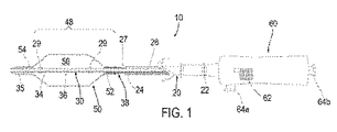
図面を参照すると、図1−2Bは、身体管腔を処置するため、例えば、流体を、血管、動静脈瘻、管状移植片(図示せず)等の身体管腔に注入するため、および/または身体管腔内で手技を行う、例えば、身体管腔内の狭窄または他の閉塞を拡張させる、身体管腔内から血栓、物体、および/または閉塞性物質を除去する、ステント、ステント移植片、人工弁、または他の補綴物(同様に図示せず)を送達する、身体管腔の中へ1つ以上の薬剤を送達すること等を行うための装置10の第1の例示的実施形態を示す。概して、装置10は、カテーテル、シース、または他の管状外側部材20と、シャフトまたは他の細長い内側部材30と、例えば、図1に示される内側部材30の遠位部分48上で、内側および/または外側部材20、30によって担持される拡張可能バルーンまたは他の処置要素50とを含む。
Referring to the drawings, FIGS. 1-2B are for treating a body lumen, for example, injecting fluid into a body lumen such as a blood vessel, arteriovenous fistula, tubular graft (not shown), and / or Or perform procedures within the body lumen, eg, dilate stenosis or other occlusions within the body lumen, remove thrombus, objects, and / or occlusive material from within the body lumen, stents, stent-grafts A first exemplary embodiment of the
装置10は、例えば、身体管腔内で種々の処置または他の機能を果たすために、例えば、身体管腔内の手技中に複数のデバイスを交換する必要性を低減または排除するために、複数のモードにおいて動作可能であり得る。例えば、装置10は、以下でさらに説明されるように、流体を身体管腔に注入するための第1のモード(図2A)と、患者の身体への導入を容易にし、および/またはバルーン50を膨張させる第2のモード(図2B)とにおいて動作可能である、例えば、密閉または弁部材38を含む弁を含んでもよい。
The
図1で最も良く見られるように、外側部材20は、ハンドル60に連結される近位端22と、身体管腔の中へ導入するようにサイズ決定された遠位端24と、近位端22と遠位端24における出口27との間に延在する第1の管腔26を含む。外側部材20は、その長さに沿って実質的に均一な構造を有してもよく、または代替として、構造が変化させられてもよい。例えば、外側部材20の近位部分は、近位端22からの装置10の前進を容易にするために実質的に剛性または半剛性であってもよく、および/または外側部材20の遠位部分は、例えば、ねじりまたは座屈の実質的なリスクを伴わずに、蛇行性生体構造を通る屈曲および/または前進を容易にするために可撓性であってもよい。例示的実施形態では、外側部材20は、金属、プラスチック、例えば、PEEK、Grilamed L25等の1つ以上の材料、または複合材料から形成されてもよい。外側部材20は、約30から130センチメートルの間(30〜130cm)の長さと、約1.2から2.0ミリメートルの間の外径とを有してもよく、第1の管腔26は、約1.0から1.8ミリメートルの間の直径を有してもよい。
As best seen in FIG. 1,
内側部材30はまた、近位端(図示せず)と、遠位端34とを含み、随意に、例えば、約0.3から1.0ミリメートルの間の直径を有するガイドワイヤ、またはそれを通る他のレール(図示せず)を摺動可能に受容するようにサイズ決定され得る、近位端と遠位先端35との間に延在する第2の管腔36を含んでもよい。代替として、図3Aに示されるように、バルーン50”の向こう側に比較的短いガイドワイヤ管腔36”を含む遠位先端35”が、装置10”(または本明細書の他の実施形態のうちのいずれか)に提供されてもよい。示されるように、ガイドワイヤ管腔36”は、遠位先端35”の遠位ポート36a”と、バルーン50”の遠位端54”に隣接する近位側面ポート36b”との間で連通してもよい。この代替案では、ガイドワイヤ(図示せず)は、例えば、ガイドワイヤが内側部材30”の全長を通して搭載される必要がないよう「迅速交換」管腔を提供するように、ガイドワイヤ管腔36”を通して遠位ポート36a”の中へ装填され戻され、近位ポート36b”から出されてもよい。したがって、この代替案では、第2の管腔36(図1−2Bに示される)が省略されてもよい。
内側部材30は、その長さに沿って実質的に均一な構造を有してもよく、または代替として、外側部材20と同様に、構造が変化させられてもよい。例えば、内側部材30は、内側部材30が屈曲または湾曲されたときにつけられる形状を成すことに抵抗し得るポリマーマトリクス、例えば、ポリイミド等の熱硬化性ポリマーマトリクスに埋め込まれた、例えば、ステンレス鋼等の金属、ポリマー強力繊維等から形成される編組、螺旋、または他の支持構造を含む複合構造から形成されてもよい。随意に、例えば、内側部材30は、図2Aおよび2Bに示されるように、弁部材38および/またはバルーン50に接着されるか、または別様に付着される、近位端32と遠位端34との間に連結されたテザーワイヤ31を含んでもよい。テザーワイヤ31は、内側部材30のシャフトに埋め込まれてもよく、または示されるように、弁部材38および/またはバルーン50以外において、シャフトに対して自由状態であるか、および/またはその外部にあってもよい。テザーワイヤ31は、例えば、内側部材30が、使用中に、近位端32と遠位端34との間において何らかの理由で壊された場合に、バルーン50が装置10から緩むことを防止するための安全特徴を提供し得る、高強度で比較的小さい断面積のワイヤまたはフィラメントであってもよい。
The
図1に戻ると、内側部材30は、例えば、以下でさらに説明されるように、それを通して1つ以上の流体を通過させるために、環状空間が外側部材20と内側部材30との間に画定されるように、外側部材20の第1の管腔26内に摺動可能に受容されるようサイズ決定される。内側部材30は、以下でさらに説明されるように、内側部材の近位端が外側部材の近位端22内に受容されるか、または例えば、ハンドル60の中へ、外側部材の近位端22を近位に越えて延在し、内側部材の遠位端34が、例えば、遠位部分48を画定するよう、外側部材20の出口27を越えて遠位に延在するように、外側部材20に対する長さを有してもよい。遠位先端35は、米国特許第8,043,313号および米国公開第2011/0125132号における実施形態と同様に、例えば、装置10用の実質的に非外傷性の先端を提供するように、丸みを帯びた、テーパ状、および/または他の形状を有してもよい。
Returning to FIG. 1, the
ハンドル60は、外側部材20の近位端22に連結されるか、またはその上に別様に提供され、例えば、締り嵌め、接着剤を用いた接着、超音波溶接、協働コネクタ(図示せず)等のうちの1つ以上によって取り付けられてもよい。アクチュエータ62は、本明細書の他の場所でさらに説明されるように、例えば、出口27を開放または閉鎖するように、および/または異なるモードの間で装置10を誘導するように、外側部材20に対して軸方向に内側部材30を誘導するために内側部材30の近位端に連結されてもよい。ハンドル60はまた、本明細書の他の場所で識別される出願における実施形態と同様に、1つ以上のポート64、例えば、第1の管腔26と連通する第1のポート64a、および第2の管腔36と連通する第2のポート64bを含んでもよい。
The handle 60 is coupled to or otherwise provided on the
バルーン50は、内側部材30の遠位部分48に連結された近位端および遠位端52、54、例えば、遠位先端35に隣接した、例えば、内側部材30に取り付けられた遠位端54、遠位先端35より近位にある内側部材30の遠位端34に取り付けられた近位端52とを含み、それにより、実質的に流体密封の内部56を画定する。例えば、バルーン50の遠位端54は、例えば、接着剤を用いた接着、締り嵌め、超音波溶接、融合、周辺スリーブまたは他のコネクタ(図示せず)との係合等のうちの1つ以上によって、流体密封接続を提供するように、内側部材30の遠位端34に、および/または遠位先端35に直接取り付けられるか、または別様に固定されてもよい。
The
バルーン50は、例えば、流体の量および/または内部56の圧力に基づいて、例えば、種々のサイズおよび/または形状に拡張され得る柔軟(compliant)または半柔軟(semi−compliant)バルーンを提供するように、弾性材料から形成されてもよい。代替として、バルーン50は、例えば、実質的に圧力とは無関係に膨張させられたときに(いったん最小容量および/または圧力が所定のサイズを達成するように導入されると)所定のサイズに膨張する非柔軟バルーンを提供するように実質的に非弾性の材料から形成されてもよい。そのような非柔軟バルーン50は、例えば、少なくとも10気圧、20気圧、30気圧等の圧力で、例えば、バルーン50が爆発するか、または別様に破裂するまで、たとえ比較的高い圧力まで膨張させられたとしても、所定のサイズに拡張してもよい。
図2Aおよび2Bで最も良く見られるように、密閉または弁部材38は、例えば、バルーン50の近位端52に隣接する、内側部材30の遠位部分48の上に、またはそれに隣接して提供される。例えば、密閉部材38は、内側部材30の外面に取り付けられてもよく、バルーン50の近位端52は、密閉部材38に取り付けられてもよい。示されるように、バルーン50の近位端52は、少なくとも部分的に密閉部材38上に延在し、例えば、接着剤を用いた接着、超音波溶接、融合、締り嵌め、外部カラー(図示せず)等によって、密閉部材38に取り付けられてもよい。したがって、バルーン50の近位端52は、密閉部材38、その結果として内側部材30と、実質的に流体密封のシールを有してもよい。
As best seen in FIGS. 2A and 2B, a sealing or
密閉部材38は、例えば、密閉部材38が出口27および/または第1の管腔26と係合させられるか、またはその中に受容されたときに、密閉部材38が出口27を実質的に密閉し得るように、概して、外側部材20の第1の管腔26に少なくとも部分的に進入するサイズを有する。例えば、図2Bで最も良く見られるように、密閉部材38は、弁本体38aと、弁本体38aの周囲に延在する1つ以上の環状弁シール38bとを含んでもよい。単一の弁シール38bのみが示されているが、例えば、結果として生じる密閉を強化させるように、弁本体38aの長さに沿って相互から軸方向に離間した複数の弁シール(図示せず)が提供されてもよいことが理解されるであろう。
The sealing
弁本体38aは、例えば、弁本体38aが出口27を通って第1の管腔26に自由に進入し得るように、第1の管腔26および/または出口27の内径よりわずかに小さい外径を有してもよい。弁シール38bは、弁本体38aが第1の管腔26に進入するときに、弁シール38bが外側部材20の内面に摺動可能に係合するように、第1の管腔26の内径よりわずかに大きい外径を有してもよい。例えば、弁シール38bは、例えば、外側部材20の内壁に対して実質的に流体密封のシールを維持するように、実質的な摩擦を生成することなく、第1の管腔26の中への摺動に適応するよう十分に圧縮性であり得るが、実質的な流体圧力の下で変形に抵抗し得るシリコーンまたは他のエラストマー、低硬度(例えば、40D)PEBAX材料、ポリウレタン等の弾性的に可撓性の材料から形成されてもよい。
The
代替として、弁シール38bは、機械的圧縮性を有する、比較的硬質で潤滑な材料、例えば、印加された負荷に応じて屈曲し得るポリウレタンの管状または他の中空の構造から形成されてもよい。弁本体38aは、例えば、弁シール38b用のより剛性の基礎または支持材を提供するように、弁シール38bとは異なる材料から形成されてもよく、または同じ材料から形成され、例えば、一体的に形成されるか、または単一の材料片から別様に形成されてもよい。したがって、弁シール38bは、使用中に装置10を別様に故障させるか、または損傷し得る過剰な力を必要とすることなく、実質的に流体密封のシールを提供するように、外側部材20の内面に摺動可能に係合してもよい。
Alternatively, the
随意に、密閉部材38は、出口27内で密閉部材38を整列させること、および/または受容することを促進するように、テーパ状形状を有してもよい。例えば、図2Aおよび2Bに示されるように、弁本体38aは、例えば、外側部材20と内側部材30とが、使用中に相互との同心整列から外れた場合、出口27および第1の管腔26の中へ密閉部材38を案内するようなテーパ状近位端38cを含んでもよい。
Optionally, the sealing
代替として、図3−4Cに示されるように、出口27’の内径よりも大きい外径を有する密閉部材38’が提供されてもよい。この代替案では、密閉部材38’はまた、例えば、密閉部材38’が少なくとも部分的に外側部材20’の出口27’内に係合するか、または受容されることを促進するために、テーパ状近位端38c’を含んでもよい。したがって、実質的に流体密封のシールを提供するために、密閉部材38’のより大きい中間部が外側部材20’の遠位端24’に隣接するまで、テーパ状近位端38c’のみが出口27’内で受容されてもよい。
Alternatively, as shown in FIGS. 3-4C, a sealing member 38 'having an outer diameter that is larger than the inner diameter of the outlet 27' may be provided. In this alternative, the sealing
図2Aおよび2Bで最も良く見られるように、密閉部材38は、密閉部材38の近位端38cと遠位端38dとの間で略長手方向に延在する1つ以上の通路39、例えば、弁本体38aに形成された複数の封入通路または溝を含んでもよい。例えば、弁本体38aは、内側部材30を受容するための孔と、端部38c、38dの間に延在する1つ以上の封入通路39とを含む押出として形成されてもよい。代替として、封入管腔が、他の方法を使用して、通路39を提供するように、管の壁内に形成されてもよい。さらなる代替案では、図3−4Cに示されるように、密閉部材38’は、その内面に形成された1つ以上の縦溝を有する1本の管類として提供されてもよい。密閉部材38’が内側部材30’に取り付けられるか、またはその周囲に別様に配置されるとき、溝は、内側部材30’の外壁に沿って延在し、それにより、一緒に通路39’を画定してもよい。
As best seen in FIGS. 2A and 2B, the sealing
加えて、または代替として、所望であれば、装置10は、使用中に装置10の設置および/または前進を促進するように、1つ以上のマーカーを含んでもよい。例えば、図1で最も良く見られるように、放射線不透過性マーカー29が、例えば、バルーン50の近位および遠位端52、54と整列して、または隣接して、内側部材30の遠位部分48上に提供されてもよい。加えて、または代替として、1つ以上の放射線不透過性マーカー(図示せず)が、外側部材の遠位端24の上、遠位先端35の上、バルーン50の上、例えば、近位および/または遠位端52、54の上、および/または密閉部材38の上に提供されてもよい。代替として、装置10の1つ以上の構成要素は、使用中に装置10の撮像を促進し得る放射線不透過性または他の材料から形成されてもよい。例えば、放射線不透過性マーカーおよび/または材料は、例えば、(拡張前または後のいずれかで)バルーン50を設置するときに、および/または出口27を介して流体を注入するときに、蛍光透視法または他のX線撮像を使用して、装置10を設置すること、または別様に撮像することを促進してもよい。代替として、音波発生マーカーおよび/または材料が、超音波または類似撮像技法を使用した撮像を促進するように提供されてもよい。
In addition or alternatively, if desired, the
図1−2Bを参照すると、組立中に、密閉部材38は、例えば、遠位部分48の所望の長さより近位で、遠位端34上の所望の場所に内側部材30の周囲に配置され、例えば、接着剤を用いた接着、超音波溶接、融合、熱収縮等によって、それに取り付けられてもよい。次いで、バルーン50の近位端52は、部分的に密閉部材38上に設置され、それに取り付けられてもよい。したがって、通路39は、密閉部材38の近位端38cの外側からバルーン50の内部56と連通してもよい。遠位先端35は、例えば、締り嵌め、接着剤を用いた接着、協働コネクタ、超音波溶接、融合等によって、内側部材30に取り付けられてもよい。バルーン50の遠位端54は、例えば、遠位先端35のより近くで、またはそれを覆って、内側部材30の遠位端34に取り付けられてもよい。その結果として、バルーン50の内部56は、密閉部材38を通して、通路39以外に実質的に密閉されてもよい。
With reference to FIGS. 1-2B, during assembly, the sealing
加えて図1を参照すると、外側部材20は、内側部材30の周囲に設置されてもよく、ハンドル60およびアクチュエータ62は、例えば、本明細書の他の場所で識別される出願で開示される実施形態と同様に、それぞれ、外側および内側部材20、30に連結されてもよい。装置10は、装置10が導入される(または別様に外側部材20の遠位端24の外部にある)身体管腔(図示せず)の中へ流体を送達するための第1のモードと、バルーン50を膨張させるための第2のモードとにおいて動作可能であり得る。
In addition, referring to FIG. 1, the
例えば、内側部材30は、密閉部材38が外側部材20の出口27から離間している、図2Aに示される第1または遠位位置と、密閉部材38が少なくとも部分的に出口27および第1の管腔26に進入する、図2Bに示される第2または近位位置との間で移動可能であり得る。第1の位置において、外側部材20の管腔26を通して送達される流体が、出口27から退出し、例えば、遠位部分48より近位の身体管腔または他の外部環境に進入してもよい。第2の位置において、弁シール38bは、管腔26を通して送達される流体が、密閉部材38内の通路39を通ってバルーン50の内部56の中へ進入し、それにより、バルーン50を膨張させ得るように、出口27を実質的に密閉してもよい。加えて、第2の位置において、例えば、所望されるときにバルーン50を崩壊させるために、内部56から膨張媒体を吸引するよう真空が第1の管腔26に印加されてもよい。
For example, the
図5を参照すると、上記で説明される装置10、10’と同様に、装置110の代替的実施形態が示される。装置110は、装置10、10’と同様に、外側部材120と、内側部材130と、バルーン150と、密閉部材138とを含む。装置110はまた、装置10、10’と同様に、第1または遠位位置と第2または近位位置との間で内側部材130を誘導することによって、第1および第2のモードにおいて動作可能であり得る。
Referring to FIG. 5, an alternative embodiment of the
しかしながら、以前の実施形態と違って、装置110は、第1および第2の位置のうちの1つに内側部材130を付勢するための、内側部材130と外側部材120との間に連結されたバネまたは他の付勢機構190を含む。例えば、示されるように、バネ190は、近位位置に向かって、すなわち、装置110の出口127が通常は閉鎖されているように、および/または密閉部材138によって出口127を密閉することを強化するために、内側部材130を付勢してもよい。付勢は、密閉部材138を外して出口127を開放するために、内側部材130を遠位に誘導することによって克服されてもよい。
However, unlike previous embodiments, the
示されるように、バネ190は、外側部材120の遠位端124に取り付けられるか、または別様に連結される第1の端部192と、内側部材130の遠位端134および/または密閉部材138に取り付けられるか、または別様に連結される第2の端部194とを含む。例えば、バネ190の第2の端部194は、密閉部材138を通って延在する通路139に依然として適応しながら、密閉部材138と内側部材130との間に、または別様に密閉部材138に取り付けられてもよい。例示的実施形態では、バネ190の端部192、194は、接着剤を用いた接着、超音波溶接、融合、締り嵌め、1つ以上のコネクタ(図示せず)等によって、内側および外側部材130、120に取り付けられてもよい。
As shown, the
バネ190と内側部材130との相対的な直径は、バネ190の過剰延長のリスクを低減させるように設定されてもよい。例えば、バネ190は、内側部材130が近位位置にあるときに、弛緩させられるか、またはわずかな張力下にあってもよく、内側部材130が遠位に誘導されたときに、より高い張力下に置かれてもよい。バネ190がより高い張力下に置かれると、バネ190の直径が減少し、それにより、バネ190と内側部材130との間の摩擦を増加させてもよい。この増加する摩擦は、バネ190の過剰延長のリスクを低減させ得、別様にバネ190を塑性的に変形させるか、または別様にバネ190が後に近位位置に向かって内側部材130を近位に付勢することを防止し得る。
The relative diameter of
図6を参照すると、図5の装置110と同様に、装置110’のさらに別の代替的実施形態が示される。装置110’は、装置110と同様に、外側部材120’と、内側部材130’と、バルーン150’と、密閉部材138’と、バネ190’とを含む。装置110’はまた、装置10、10’と同様に、第1または遠位位置と第2または近位位置との間で内側部材130’を誘導することによって、第1および第2のモードにおいて動作可能であり得る。
Referring to FIG. 6, similar to
加えて、装置110’は、本明細書の他の場所で識別される出願における実施形態と同様に、拡張した螺旋形状に拡張され得る螺旋部材170’をバルーン150’内に含む。例えば、螺旋部材170’は、外側部材120’に連結される第1または近位端(図示せず)と、バルーン150’の遠位端154’に隣接する内側部材130’に連結される第2または遠位端174’とを含んでもよい。したがって、装置110’はまた、例えば、第2の位置から、螺旋部材170’が軸方向に圧縮され、および半径方向に拡張される第3の位置へ、内側部材130’を近位に誘導することによって、第3のモードで操作されてもよい。バルーン150’は、本明細書の他の場所において識別される出願における実施形態と同様に、螺旋部材170’が拡張されている間、崩壊させられたままであってもよく、または膨張させられ、次いで、螺旋部材170’が拡張された後に崩壊させられてもよい。
In addition, the
螺旋部材170’およびバルーン150’が拡張された螺旋形状内の物質を除去するために使用された後、内側部材130’は、螺旋部材170’を内側部材130’の周囲でその元の収縮形状に戻すように、遠位に誘導されてもよい。この作用が、バネ190’を延長させ、出口127’を開いてもよい。しかしながら、上記で論議されるように、バネ190’および内側部材130’の相対サイズは、バネ190’が延長して内側部材130’に摩擦係合するにつれて圧縮し、それにより、内側部材130’が遠位に誘導されている間にバネ190’の過剰延長のリスクを低減するようなものであってもよい。
After the
図21A−22Bを参照すると、上記で説明される装置10、10’に類似し得る、装置810の別の実施形態が示される(または装置810の特徴のうちの1つ以上が、本明細書で説明される実施形態のうちのいずれかに組み込まれてもよい)。装置810は、概して、装置10、10’と同様に、近位および遠位端822、824を含む、外側部材820と、近位および遠位端832、834を含む、内側部材830と、近位および遠位端852、854を含む、バルーン850と、密閉部材838とを含む。
Referring to FIGS. 21A-22B, another embodiment of the
装置810はまた、「J」型先端または他の湾曲形状を有する、内側部材830の遠位端834から延在する可撓性遠位先端835も含む。随意に、遠位先端835は、バルーン850から遠位に狭小化するテーパ状形状を有してもよく、または所望であれば実質的に均一な断面(図示せず)を有してもよい。遠位先端835は、湾曲形状に付勢されてもよいが、例えば、図21Cに示されるように、遠位先端835を通して、遠位先端835よりも優れた剛性を有するガイドワイヤまたは他のレール99を誘導することによって、遠位先端835が少なくとも部分的に真っ直ぐにされ得るように、弾性的に可撓性であってもよい。したがって、ガイドワイヤ99が遠位先端835から除去されると、遠位先端835は、例えば、患者の身体を通した装置810の前進を促進するように、図21Aおよび21Bに示されるように、その湾曲形状を弾性的に採用してもよい。しかしながら、所望であれば、遠位先端835は、例えば、図21Cに示されるように、ガイドワイヤ99上で装置810を前進させることに適応するように、それを通してガイドワイヤ99を導入することによって、真っ直ぐにされてもよい。
The
装置810は、本明細書の他の実施形態と同様に、弁が開いている第1または遠位位置(図22A参照)と、弁が閉鎖されている第2または近位位置(図22B参照)との間で内側部材830を誘導することによって、第1または第2のモードにおいて動作可能であり得る。例えば、本明細書の他の実施形態と同様に、ハンドル860が、外側部材の近位端822上に提供されてもよく、アクチュエータ862が、内側部材830の近位端832に連結されてもよい。アクチュエータ862は、軸方向に、すなわち、近位および遠位位置の間で内側部材830を誘導するためのハンドル860に対して近位および遠位に、移動可能であり得る。
The
加えて、以前の実施形態とは違って、アクチュエータ862および内側部材830は、装置810の長手軸の周囲で回転可能であり得る。したがって、アクチュエータ862は、内側部材830を回転させ、それにより、湾曲遠位先端835の配向を変化させるように、ハンドル860に対して回転させられてもよい。例えば、図21Aおよび21Bは、ハンドル860に対して約180度(180°)アクチュエータ862を回転させることによって達成され得る、反対配向での湾曲遠位先端835を示す。したがって、遠位先端835の配向を変化させるように、装置810全体を回転させる、すなわち、外側および内側部材820、830の両方を含むよりもむしろ、内側部材830のみが回転させられる必要がある。装置810全体が回転させられる場合、外側部材820は、例えば、外側部材820が不良なトルク伝達を有するポリマー材料から形成されている場合、ねじりするか、または別様にその近位および遠位端822、824の間で実質的なトルクを伝達できなくなり得る。代わりに、内側部材830は、外側部材820から分断され、すなわち、その中で自由に回転可能であり、それにより、近位および遠位端832、834の間でトルクを自由に伝達することを促進してもよい。
In addition, unlike previous embodiments,
内側部材830の近位および遠位端832、834の間のそのような回転の伝達を促進するために、内側部材830のシャフトは、ねじりに抵抗する複合または他の構造から形成されてもよい。例えば、内側部材830は、ポリマーマトリクス(例えば、内側部材830が屈曲または湾曲されたときにつけられる形状を成すことに抵抗し得る、ポリイミド等の熱硬化性ポリマーマトリクス)内のステンレス鋼(または他の金属またはポリマー強力繊維)編組から形成されてもよい。そのような構造は、近位および遠位端832、834の間で実質的なトルク伝達も維持しながら、良好な可撓性を提供してもよい。
To facilitate transmission of such rotation between the proximal and
アクチュエータ862は、所望であれば、ハンドル860に対して自由に回転可能であり得る。代替として、協働特徴(図示せず)が、アクチュエータ862および内側部材830の回転を制限するように、例えば、ハンドル860および内側部材830の上に提供されてもよい。例えば、回転を360度(360°)未満に制限するように相互作用する、1つ以上の戻り止めおよび/または進路(図示せず)が、ハンドル860内に、および/または内側部材830の近位端832の上に提供されてもよい。したがって、ユーザは、そうでなければ内側部材830に過剰なトルクを印加し得る、1つの方向への過剰な回転を制限しながら、完全回転に近い湾曲遠位先端835の配向を変化させるようにアクチュエータ862を回転させることが可能であり得る。
外側部材820に対する内側部材830の回転を可能にするために、アクチュエータ862が第1の位置に誘導されてもよく、それにより、弁を開放し、密閉部材838から、その結果として、内側部材830から外側部材820の遠位端824を分断する。第1の位置において、内側部材830が、遠位先端835の配向を変化させるように、外側部材820に対して回転させてもよい。
To allow rotation of the
随意に、密閉部材838および/または外側部材820は、例えば、弁が閉鎖された状態で、第2の位置で内側部材830の回転を可能にするよう、その間の摩擦を最小限化するように構築されてもよい。この選択肢において、比較的低い摩擦係数を有する材料、例えば、PTFE、ポリエチレン等が、例えば、密閉部材838の外面上および/または外側部材820の遠位端824の内面上に提供されてもよい。したがって、弁を開いて外側および内側部材820、830を分断する必要があるよりむしろ、部材は、弁が閉鎖されていても相互に対して自由に回転してもよい。
Optionally, sealing
図1−2Bに戻ると、装置10(または本明細書の実施形態のうちのいずれか)は、1つ以上の処置および/または診断的医療手技を行うように、例えば、患者の血管系または他の天然あるいは外科的に作成された通路を介して、身体管腔(図示せず)に導入されてもよい。例示的実施形態では、標的身体管腔は、血管、例えば、静脈または動脈、移植片、例えば、動静脈瘻、管状異種移植片、または合成管状移植片等であり得る。例えば、身体管腔は、例えば、透析患者の腕または他の領域中で、隣接する動脈と静脈(図示せず)との間で連通する通路であり得る。代替として、身体管腔は、患者の血管系内の血管、例えば、患者の脚の末梢血管、脳血管等であってもよい。さらなる代替案では、物質は、患者の身体から除去される、患者の尿路内の結石または他の異物であり得る。さらに別の代替案では、身体管腔は、大動脈または心腔、例えば、修復、置換、または他の処置を必要としている心臓弁の部位であり得る。 Returning to FIGS. 1-2B, the device 10 (or any of the embodiments herein) may be configured to perform one or more procedures and / or diagnostic medical procedures, for example, the patient's vasculature or It may be introduced into a body lumen (not shown) via other natural or surgically created passages. In an exemplary embodiment, the target body lumen can be a blood vessel, such as a vein or artery, a graft, such as an arteriovenous fistula, a tubular xenograft, or a synthetic tubular graft. For example, a body lumen can be a passage that communicates between adjacent arteries and veins (not shown), for example, in the arm or other area of a dialysis patient. Alternatively, the body lumen may be a blood vessel in the patient's vasculature, such as a peripheral blood vessel, a cerebral blood vessel, etc. in the patient's leg. In a further alternative, the substance may be a stone or other foreign body in the patient's urinary tract that is removed from the patient's body. In yet another alternative, the body lumen can be the aorta or heart chamber, eg, the site of a heart valve in need of repair, replacement, or other procedure.
随意に、身体管腔は、装置10を含むシステムまたはキットの一部であり得る、1つ以上の付加的な器具(図示せず)を使用してアクセスされてもよい。例えば、導入器シース、ガイドカテーテル、または他の管状部材(図示せず)が、物質が除去される標的処置部位に隣接して導入されてもよく、または患者の血管系または身体管腔と連通する他の通路へのアクセスを提供するように患者の体内の他の場所に導入されてもよい。身体管腔が患者の血管系の末梢血管内に位置する場合、大腿動脈、頸動脈、または他の進入部位(図示せず)等の末梢位置で針または他の器具(同様に図示せず)を使用して、経皮的穿孔または切開が作成されてもよく、導入器シースが、アクセスを提供するように末梢位置で穿孔を通して配置されてもよい。装置10は、例えば、単独で、またはガイドカテーテル、ガイドワイヤ等(図示せず)を用いて、進入部位から患者の血管系を通して前進させられてもよい。
Optionally, the body lumen may be accessed using one or more additional instruments (not shown) that may be part of a system or kit that includes the
例えば、進入部位から標的身体管腔へ装置10を誘導することを促進するために、従来の方法を使用して、ガイドカテーテル、マイクロカテーテル、または他の管状本体が、進入部位から身体管腔へ配置されてもよい。加えて、または代替として、例えば、内側部材30が第2の管腔36を含む場合、ガイドワイヤ(図示せず)が、所望であれば、進入部位から身体管腔へ配置されてもよい。代替として、装置10が迅速交換ガイドワイヤ管腔をその遠位先端に含む場合、ガイドワイヤに沿って装置10を前進させることを促進するように、ガイドワイヤが遠位先端を通して装填され戻されてもよい。随意に、以下でさらに説明されるように、例えば、装置10によって除去された物質を捕捉するための真空源に連結された、ガイドカテーテルまたは管状本体もまた、吸引に使用されてもよい。
For example, to facilitate guiding the
最初に、図2Bを参照して、内側部材30が第2の位置にあり、密閉部材38が出口27を実質的に密閉している状態で、装置10が提供されてもよい。この位置で、密閉部材38はまた、例えば、装置10が蛇行性生体構造を通して前進させられたときに、例えば、身体管腔の壁を損傷する最小限のリスクを伴って、装置10の前進を促進し得る、(出口27の密閉に加えて)外側部材20の遠位端24の実質的に平滑な平行移動を提供してもよい。代替として、装置10は、装置10の操作中に流体の送達を促進するように、所望であれば、内側部材30が第1の位置にある状態で、すなわち、出口27が開いている状態で、導入されてもよい。
First, with reference to FIG. 2 B, there is an
装置10が、例えば、図21A−22Bに示される装置810と同様に、湾曲遠位先端(図示せず)を含む場合、遠位先端は、ガイドワイヤまたは他のレール上の前進中に真っ直ぐにされてもよい。遠位先端をその湾曲形状で展開することが所望される場合、ガイドワイヤは、遠位先端から除去されるまで部分的に引き出されてもよく、そうするとすぐに、遠位先端がその湾曲形状に弾性的に戻ってもよい。次いで、分岐にアクセスするか、または別様に1つの身体管腔から別の身体管腔の中への装置10の前進を促進するように、例えば、内側部材が外側部材または装置10全体とは無関係に回転可能である場合に内側部材を回転させることによって、湾曲先端が回転させられてもよい。例えば、いったん湾曲先端が回転させられ、例えば、身体管腔に隣接する分岐の中へ遠位先端を前進させるように、装置が十分に身体管腔内で操作されると、遠位先端を真っ直ぐにし、装置10をさらに前進させる前にガイドワイヤを前進させるように、ガイドワイヤが再び前進させられてもよい。
If the
任意の時に、身体管腔の中へ流体を送達することが所望される場合、外側部材20の遠位端24から密閉部材38を離間させて、出口27を開放するように、内側部材30が、遠位または第1の位置に(まだそこになければ)誘導されてもよい(図2A)。次いで、流体は、外側部材の管腔26を通って出口27から出て、身体管腔の中へ送達されてもよい。出口27が密閉部材38から離間されるため、流体の実質的に全てが身体管腔に注入され、バルーン50の中へ通路39を通過しない。
If at any time it is desired to deliver fluid into the body lumen, the
例えば、放射線不透過性造影剤または他の流体が、遠位部分48および/または標的処置部位の場所を監視および/または識別することを促進するように、外側および内側部材20、30の間で第1の管腔26によって画定される環状通路を介して、身体管腔の中へ送達されてもよい。装置10上のマーカー29(および/または示されていない他のマーカー)が、処置部位に対してバルーン50を設置することを促進してもよい。例えば、造影剤は、例えば、バルーン50が処置部位内に、または処置部位に隣接して設置されていると検証することを促進するように、バルーン50が拡張する前に、身体管腔内で拡張または除去されることを目的としている閉塞性物質、補綴物の埋込部位等を識別することを促進してもよい。
For example, between the outer and
図2Bで最も良く見られるように、バルーン50を拡張すること(および/または別様に遠位部分48上の示されていない別の処置要素を伴う手技を行うこと)が所望されるとき、内側部材30は、例えば、密閉部材38で出口27を実質的に密閉するように、近位または第2の位置に誘導されてもよい(または自動的に付勢されてもよい)(図2B)。密閉部材38は、第1の管腔26を通した後続の流体送達が、流体を、バルーン50の内部56の中へと密閉部材38の通路39に通過させ、それにより、バルーン50を膨張させるように、出口27の実質的に流体密封のシールを提供してもよい。
As best seen in FIG. 2B, when it is desired to expand the balloon 50 (and / or otherwise perform a procedure with another treatment element not shown on the distal portion 48)
例えば、例示的な手技中に、装置10は、遠位部分48およびバルーン50が身体管腔内の閉塞領域を越えて遠位に設置されるまで、設置されてもよい。内側部材30が第2の位置で出口27を密閉していると、例えば、バルーン50が実質的に身体管腔を完全に横断して延在するように、バルーン50が身体管腔内で膨張させられてもよい。次いで、装置10全体が、例えば、ガイドカテーテル(図示せず)に吸引されるか、または別様に身体管腔から除去されるように、身体管腔から物質を引き抜くよう後退させられてもよい。随意に、バルーン50は、例えば、身体管腔内の物質の除去を促進するように、本明細書の他の場所で識別される出願における装置と同様に、螺旋構成に指向可能であり得る。
For example, during an exemplary procedure, the
いったん物質が除去されると、内側部材30が、第2の位置に向かって戻されてもよく、身体管腔内で除去された、および/または残っている物質の量を観察するように、流体が出口27を通して導入されてもよい。付加的な物質が除去される場合、内側部材30は、例えば、除去される付加的な物質を通して装置10を前進させることが所望されるならば、第1の位置に誘導されてもよい。いったんバルーン50が物質を越えて位置すると、バルーン50の位置および/または除去の進捗を監視するように、弁が開閉されている状態で所望されるのと同じくらい頻繁に、プロセスが繰り返されてもよい。
Once the material has been removed, the
加えて、所望であれば、閉塞性物質は、引き出す前、間、また後に、処置される、例えば、少なくとも部分的に溶解させられる、温浸させられる等が行われてもよい。例えば、バルーン50によって除去される前に血栓または他の比較的軟質の物質を少なくとも部分的に溶解させるか、または分離し、および/または身体管腔の壁を別様に処置するように、例えば、処置薬が、第1の管腔26および外側部材20の出口27を介して身体管腔の中へ送達されてもよい。
In addition, if desired, the occlusive material may be treated before, during and after withdrawal, eg, at least partially dissolved, digested, etc. For example, to at least partially dissolve or separate the thrombus or other relatively soft material and / or otherwise treat the wall of the body lumen before being removed by the
例えば、物質を除去し、閉塞を拡張させ、および/または別様に身体管腔を処置するようにバルーン50を膨張させた後に、バルーン50を折り畳むために、流体が、内部56から通路39および第1の管腔26を通して排出されてもよい。代替として、内側部材30は、密閉部材38から係脱して出口27を開放するように、第1の位置に向かって誘導されてもよい。次いで、バルーン50内の流体は、通路39を通って身体管腔の中へ自由に出て行き、吸引を必要とすることなくバルーン50を膨張させてもよい。
For example, after inflating the
随意に、所望であれば、内側部材30は、中間位置に、すなわち、以下でさらに説明されるように、いくらかの流体が通路39に進入してバルーン50を拡張する一方、残っている流体が身体管腔内に送達されるように、出口27から送達される流体が分割され得る、例えば、図15Bに示されるような第1および第2の位置の間に、設置されてもよい。膨張および身体管腔の中への流体送達の相対量は、単純に、出口27により近く、または出口27からより遠く、密閉部材38を移動させるように、内側部材30を近位または遠位に誘導することによって、所望の通り、調整されてもよい。この手技は、バルーン50の膨張および/または位置、および/またはその内側にバルーン50が位置する周辺血管系を監視するように、例えば、流体が放射線不透過性造影剤を含む場合に、外部撮像を使用して達成されてもよい。
Optionally, if desired, the
別の選択肢において、装置10は、出口27を使用して流体を送達および吸引するように使用されてもよい。例えば、ユーザが、装置10を使用して、身体管腔内で1つ以上の診断および/または処置薬を送達および除去することを所望し得る。一実施例では、撮像を促進するための造影剤、染料、または他の物質が、(内側部材30および密閉部材38が第1の位置にある状態で)出口27から身体管腔の中へ送達され、次いで、身体管腔内に残るか、または患者の体内の他の場所へ移動する造影剤の量を低減させるように、出口27の中へ再び吸引されてもよい。加えて、または代替として、外側部材20は、例えば、遠位端24に隣接する外部環境の中へ/から物質を送達および/または吸引するために、所望であれば、近位および遠位端22、24の間に延在する1つ以上の付加的な管腔(図示せず、例えば、図14B参照)を含んでもよい。
In another option, the
別の実施例では、例えば、身体管腔内の血塊または他の物質を破壊するように、細胞融解剤が身体管腔の中へ送達されてもよく、次いで、遊離した物質が、管腔26を通して出口27の中へ(または装置10の上に設置される、示されていないガイドカテーテルの中へ)吸引されてもよく、細胞融解剤を患者の身体に全身的に流出または別様に暴露させるリスクを低減し得る。次いで、出口27はまた、薬剤によって溶解または破壊されていない、および/または別様に身体管腔内で緩くなった血栓または他の物質の断片を吸引するために使用されてもよい。そのような手技中に、1つ以上の薬剤が送達および吸引されている間に、身体管腔の中へ送達される薬剤への他の場所の暴露も低減し得る、身体管腔を通る流動を停止または低減させるように、例えば、図15Bに示されるように内側部材30を中間位置に誘導することによって、バルーン50は、少なくとも部分的に膨張させられてもよい。
In another example, a cell thawing agent may be delivered into the body lumen, for example to destroy blood clots or other materials within the body lumen, and the released material is then passed through the
本明細書で説明される装置10および手技を用いて、第1の管腔26は、バルーン50の膨張および身体管腔の中への流体の送達の両方に使用されてもよい。したがって、外側部材20、したがって、全体的な装置10の外形は、別個の膨張および注入の管腔を含むデバイスより小さくあり得る。さらに、内側部材30の第2の管腔36を流体の注入に使用することができるが、これは、概して、ガイドワイヤが第2の管腔36を実質的に充填し得るため、その上に装置10が導入されるガイドワイヤを除去することを要求するであろう。第1の管腔26が注入に使用され得るため、ガイドワイヤが手技の全体を通して第2の管腔36内に残り、それにより、ガイドワイヤまたは他のデバイス交換の数を潜在的に低減させ得る。さらに、装置10は、ガイドワイヤ上に残り得、本明細書の他の場所で識別される出願で説明されるように、処置のために意図された他の標的身体管腔まで装置10を前進させることを促進してもよい。
Using the
図16Aを参照すると、別の例示的方法において、身体管腔90が、閉塞94、例えば、血管内の部分的または慢性完全閉塞を含み得、装置10が、閉塞94を拡張させ、および/または別様に処置するために導入されてもよい。示されるように、ガイドワイヤ99が、例えば、既知の方法を使用して、進入部位(図示せず)から身体管腔90の中へ、閉塞94を通して追跡されている。身体管腔90を通る流動がないので、撮像を容易にするために従来の染料注入を行う機会がほとんどないので、慢性完全病変は、特に処置することが困難であり得る。さらに、染料注入を使用することなしには、身体管腔90内でガイドワイヤ99および/または装置10を追跡する、および/または設置することが困難であり得る。
Referring to FIG. 16A, in another exemplary method,
最初に、装置10は、バルーン50がその崩壊状態にあるとき、身体管腔90の中へ前進させられてもよい。例えば、装置10は、例えば、示されるように、バルーン50の遠位端54が閉塞94を越えて身体管腔90の領域に進入するまで、閉塞94を通して以前に配置されたガイドワイヤ99上を前進させられてもよい。バルーン50が少なくとも部分的に閉塞94内に設置されると、内側部材30は、出口27を開放するように誘導されてもよく、放射線不透過性造影剤、染料、または他の流体(95によって表される)が、例えば、蛍光透視法を使用して閉塞94の物質および/または身体管腔90のサイズの位置特定および/または測定を促進するために、外側部材20と内側部材30との間に第1の管腔26によって画定される環状通路を介して、身体管腔90の中へ送達されてもよい。装置10上のマーカー29(図16Aでは示されていない、図1参照)は、例えば、バルーン50が閉塞94を通して、および/または横断して設置されていることを検証することを容易にするために、バルーン50が拡張される前に閉塞94に対してバルーン50を設置することを容易にしてもよい。所望であれば、内側部材30は、例えば、造影剤の注入およびバルーン50の膨張を可能にして、閉塞94を拡張させ、処置の進捗を監視するために、第1の位置と第2の位置との間で前後に誘導されてもよい。
Initially, the
したがって、装置10は、適所にガイドワイヤ99を維持しながら、閉塞94に隣接する染料注入を促進してもよい。装置10と異なり、従来のデバイスは、閉塞94の周囲での染料注入および撮像を可能にするために、閉塞94を通して前進させられたガイドワイヤまたは他のデバイスを除去することを要求し得る。そのような手技では、閉塞94を通して作成された小さい通路を再び通して、ガイドワイヤまたはデバイスを再導入することが困難であり得る。
Thus, the
所望であれば、閉塞性物質は、引き出す前、間、また後に、処置され、例えば、少なくとも部分的に溶解させられ、温浸させられる等が行われてもよい。例えば、バルーン50によって拡張させられる前に血栓または他の比較的軟質の物質を少なくとも部分的に溶解させるか、または分離するように、例えば、処置薬が、第1の管腔26および外側部材20の出口27を介して身体管腔90の中へ送達されてもよい。加えて、または代替として、遠位部分48は、バルーン50に加えて、またはその代わりに、1つ以上の他の処置要素、例えば、研磨先端、受動または能動的アテローム切除術用ツール等(図示せず)を担持してもよい。例示的な先端およびそれらを使用するための方法は、米国公開第2011/0172598号として公開された、2010年12月13日出願の出願第12/966,925号で開示されている。
If desired, the occlusive material may be treated before, during, or after withdrawal, eg, at least partially dissolved, digested, etc. For example, the treatment agent may be, for example, treated with the
随意に、図16Bに示されるように、ステント96は、バルーン50によって担持されてもよく、およびバルーン50を膨張させるために拡張されてもよい。例えば、装置10の弁が開いていると、染料95が、装置10の撮像および設置を促進するように、身体管腔90に注入されてもよい。いったんステント96が閉塞94を横断して設置されると、弁が閉鎖されてもよく、バルーン50が、ステント96を拡張して閉塞94(図示せず)を拡張させるように、膨張させられてもよい。いったんステント96が拡張されると、バルーン50が崩壊させられてもよく、装置10が身体管腔90および患者の身体から除去されてもよい。
Optionally, as shown in FIG. 16B, the
代替として、装置10は、ステント96の代わりに、またはそれに加えて、他の補綴物を導入および/または展開するために使用されてもよい。例えば、管状ステント移植片、人工弁の1つ以上の構成要素等(図示せず)が、例えば、バルーン50上で、遠位部分48によって担持されてもよい。補綴物は、例えば、所望の通り、選択的に導入されている流体を用いて、上記で説明されるようにバルーン50を膨張させることによって、身体管腔内で拡張されるか、または別様に展開されてもよい。
Alternatively, the
図16Cを参照すると、別の方法では、装置10”が、閉塞94を処置するための薬剤送達プラットフォームとして使用されてもよい。例えば、いくつかの用途では、ステントを伴わずに抗再狭窄剤を送達することが望ましくあり得る。示されるように、装置10”は、身体管腔90の中へ、および/または閉塞94”を通して送達され得る、バルーン50”上に提供される担体98”を含む。例えば、上記で説明される方法と同様に、装置10”は、例えば、ガイドワイヤ99上で、バルーン50”および担体98”がその上で折り畳み状態にあると、身体管腔90の中へ前進させられてもよい。
Referring to FIG. 16C, in another method,
バルーン50”が閉塞94内に設置され、弁が開いていると、造影剤、染料、または他の流体95が、例えば、蛍光透視法を使用して、閉塞94および/または身体管腔90のサイズの位置特定および/または測定を促進するように、出口27”から身体管腔90の中へ送達されてもよい。いったんバルーン50”が閉塞94を横断する状態で装置10”が設置されると、弁が閉鎖されてもよく、閉塞94を拡張させて担体98”を送達するように、バルーン50”が身体管腔90内で膨張させられてもよい。いったん担体98”が送達されると、バルーン50”が崩壊させられてもよく、装置10”が身体管腔90および患者の身体から除去されてもよい。1つ以上の処置薬が、担体98”内に設置されるか、またはそれによって別様に担持されてもよく、したがって、身体管腔90を処置するように拡張させられた閉塞94内に残ってもよい。
When the
代替として、薬剤は、バルーン50”の壁から直接送達されてもよい。例えば、薬剤は、例えば、薬剤が埋め込まれるか、または別様に配置され得る、多孔質層をバルーン50”の上に提供することによって、バルーン50”の壁を通して注入されてもよい。別の代替案では、身体管腔90の中へ送達される薬剤は、いったん身体管腔90内でともに送達されると、原位置で反応または相互作用し得る、複数の構成要素から提供されてもよい。例えば、第1の構成要素(または、薬剤の全ての構成要素よりも少ない1つ以上の付加的な構成要素)が、上記で説明されるように、例えば、バルーン50”の周囲に配置された多孔質層内で、または担体98”上で、バルーン50”の壁の上に担持されてもよい。第2の構成要素(または薬剤に必要とされる複数の残りの構成要素)が、装置10”上の出口27”を介して送達されてもよい。例えば、弁を閉鎖し、閉塞94内でバルーン50”を膨張させることによって、1つ以上の構成要素が送達された後に、弁が開放されてもよく、1つ以上の残りの構成要素を担持流体が、身体管腔90の中へ送達されてもよい。次いで、構成要素は、閉塞94の物質を処置するか、および/または身体管腔90を別様に処置し得る、活性剤または薬剤を形成するように合体してもよい。
Alternatively, the drug may be delivered directly from the wall of the
別の代替案では、本明細書の他の場所で識別される出願における実施形態と同様に、バルーン(図示せず)が、所望であれば、外側部材20の遠位端24の上に、またはバルーン50より遠位にある内側部材30の遠位部分48の上に提供されてもよい。そのようなバルーンは、例えば、身体管腔を拡張させるための非柔軟高圧バルーン、またはその中に流体を注入する前に身体管腔の1つ以上の領域を隔離するように身体管腔を実質的に密閉するための弾性柔軟バルーンであってもよい。そのような代替案では、外側および/または内側部材20、30は、例えば、図14A−14Cに示されるように、1つ以上の付加的な管腔を含み、そのような付加的なバルーン用の膨張管腔を提供してもよい。
In another alternative, a balloon (not shown), if desired, over the
図7A−7Cを参照すると、管状外側部材220と、細長い内側部材230と、処置要素、例えば、カバーまたは他の拘束部298によって覆われたステントまたは他の補綴物296を担持する遠位部分248とを含む、装置210の別の実施形態が示される。概して、装置210は、本明細書の他の実施形態と同様に、遠位部分248に隣接する弁を開閉するために、第1または遠位位置と第2または近位位置との間で内側部材230を誘導することによって、複数のモード、例えば、第1および第2のモードにおいて動作可能であり得る。加えて、装置210は、以下でさらに説明されるように、遠位部分248上に担持される補綴物を展開するために動作可能であり得る。
With reference to FIGS. 7A-7C, a
外側部材220は、ハンドル260に連結される近位端222と、身体管腔の中へ導入するためにサイズ決定される遠位端224と、近位端222と遠位端224における出口227との間に延在する第1の管腔226とを含む。内側部材230はまた、近位端232と、遠位端234とを含み、随意に、近位端232と遠位先端235との間に延在する第2の管腔236を含んでもよい。加えて、内側部材230は、以下でさらに説明されるように、拘束部298を選択的に作動させる、例えば、拘束部を遠位に前進させるか、または別様に補綴物296を展開するために、拘束部298と連結された、例えば、アクチュエータ管腔(図示せず)内に摺動可能に配置される、アクチュエータ部材(同様に図示せず)を含んでもよい。
The
内側部材230は、内側部材の近位端232がハンドル260上のアクチュエータ262に連結され、内側部材の遠位端234が、例えば、遠位部分248を画定するよう、外側部材220の出口227を越えて遠位に延在するように、外側部材220に対する長さを有してもよい。アクチュエータ262は、本明細書の他の実施形態と同様に、例えば、出口227を開放または閉鎖するために、および/または異なるモード間で装置210を誘導するために、外側部材220に対して軸方向に内側部材230を誘導するように、内側部材230の近位端232に連結されてもよい。
以前の実施形態と違って、遠位部分248は、少なくとも部分的に近位部分238と遠位先端235との間に延在する、テーパ状近位部分238に隣接する補綴物296および拘束部298を含む。テーパ状部分238は、本明細書の他の実施形態と同様に、例えば、出口227を選択的に密閉するための密閉部材を提供するために、内側部材230から外向きおよび遠位にテーパ状になり、外側部材220の出口227に類似する、またはそれよりも大きい外径を画定してもよい。テーパ状部分238は、遠位部分248の他の部分に類似する材料から形成されてもよく、またはテーパ状部分238は、出口227との密閉を強化するために可撓性および/または弾性材料から形成されてもよい。
Unlike previous embodiments, the
内側部材230は、出口227が近位部分238から離間している、図7Bに示される第1または遠位位置と、テーパ状部分238が出口227を実質的に密閉するように出口227に係合している、図7Aに示される第2または近位位置との間で移動可能であり得る。例えば、アクチュエータ262は、例えば、流体が、第1の管腔226から出口227を通して、遠位部分248に隣接する身体管腔または他の領域の中へ送達されることを可能にするよう示されるように、出口227を開閉するようハンドル260上の遠位および近位位置の間で誘導されてもよい。
The
遠位部分248は、テーパ状部分238の最大直径に類似する外径、例えば、テーパ状部分238と遠位先端235との間の実質的に均一な直径を有してもよい。代替として、遠位部分248は、例えば、その上に補綴物296を受容することに適応するように、テーパ状部分238から漸減してもよい。
The
示されるように、拘束部298は、ステント296の上に横たわる第1の位置およびステント296を露出するための第2の位置から移動可能であり得る。図7Cで最も良く見られるように、ハンドル260上のアクチュエータ266は、ステント296を露出させるために、内側部材230内のアクチュエータ部材(図示せず)を遠位に前進させ、その結果として拘束部298を遠位に誘導してもよい。示される実施形態では、ステント296は、自己拡張式であってもよく、すなわち、ステント296が内側において展開されることが意図されている身体管腔よりも大きい直径まで拡張するように付勢されてもよい。したがって、拘束部298が前進させられるとき、拘束部298がステント296全体を露出させるように十分前進させられるまで、ステント296は、露出させられるにつれて弾性的に拡張してもよい。代替として、他の拘束部、例えば、ステント296を包囲し、および/または収縮状態で遠位部分248上のステント296を固定し得るが、収縮状態からステント296を解放し、ステント296が展開状態に弾性的に拡張することを可能にするように引き出され得る1つ以上のフィラメントまたは要素(図示せず)が、示されているスリーブ298の代わりに提供されてもよい。
As shown, the
加えて、または代替として、バルーンまたは他の拡張可能部材(図示せず)が、例えば、ステント296の下に横たえられて、遠位部分248の上に提供されてもよい。この実施形態では、バルーンは、流体がバルーンの内部の中へと出口227およびテーパ状部分238内の1つ以上の通路(図示せず)を通過するように、例えば、内側部材230が第2の位置にある状態で第1の管腔226を通して流体を送達することによって、膨張させられてもよい。例えば、バルーンは、展開後に塑性的または別様にさらにステント296を拡張させ、および/またはステント296がその内側で展開される身体管腔を拡張させるように、膨張させられてもよい。
In addition or alternatively, a balloon or other expandable member (not shown) may be provided over the
さらなる代替案では、ステント296は、例えば、本明細書の他の場所で説明される実施形態と同様に、塑性的に拡張可能であってもよい。この代替案では、ステント296(または他の補綴物)を保護し、および/または遠位部分248上での移行を提供することが所望される場合、拘束部298が依然として提供されてもよい。代替として、拘束部298が省略されてもよく、ステント296は、例えば、ステント296を圧縮することによって、または収縮状態に対応する実質的に弛緩した状態を有するステント296によって、遠位部分248の上に維持されてもよい。この代替案では、バルーンまたは他の拡張可能部材(図示せず)が、本明細書の他の実施形態と同様に、ステント296を拡張するために遠位部分248の上に提供されてもよい。
In a further alternative, the
図8Aおよび8Bを参照すると、管状外側部材320と、細長い内側部材330と、処置要素、例えば、バルーン、ステント、または他の補綴物等(図示せず)を担持し得る遠位部分348とを含む、装置310の別の実施形態が示される。外側部材320は、ハンドル(図示せず)に連結される近位端と、身体管腔の中へ導入するためにサイズ決定される遠位端324と、近位端と遠位端324における出口327との間に延在する第1の管腔326とを含む。
Referring to FIGS. 8A and 8B, a tubular
内側部材330はまた、近位端(図示せず)と、遠位端334とを含み、随意に、近位端と遠位先端335との間に延在する第2の管腔336を含んでもよい。内側部材330は、遠位部分348に隣接する弁を開閉するために、例えば、図8Aに示される第1または遠位位置と、図8Bに示される第2または近位位置との間で内側部材330を誘導するためのハンドル上のアクチュエータ(図示せず)に連結されてもよい。
例えば、示されるように、遠位部分348は、テーパ状近位部分338から遠位先端335まで延在してもよい。図7A−7Cに示される装置210と同様に、テーパ状部分338は、本明細書の他の実施形態と同様に、例えば、出口327を選択的に密閉するための密閉部材を提供するために、内側部材330から外向きおよび遠位にテーパ状になり、外側部材320の出口327に類似する、またはそれより大きい外径を画定してもよい。テーパ状部分338は、遠位部分348の他の部分に類似する材料から形成されてもよく、またはテーパ状部分338は、出口327とのシールを強化するために、可撓性および/または弾力性材料から形成されてもよい。代替として、別個の密閉部材(図示せず)が、例えば、以前に説明された密閉部材38、38’と同様に、内側部材330の遠位端334の上に形成されるか、またはそれに取り付けられてもよい。この代替案では、遠位部分348は、内側部材330の他の部分に類似する直径を有してもよい。
For example, as shown, the
示されるように、遠位部分348は、例えば、テーパ状部分338における1つ以上の近位ポート339aから、例えば、遠位先端335に隣接する、遠位部分における1つ以上のそれぞれの遠位ポート339bまで、少なくとも部分的にその長さに沿って延在する1つ以上の通路339を含んでもよい。随意に、遠位部分348は、以前の実施形態と同様に、バルーンまたは他の拡張可能部材(図示せず)、ステントまたは他の補綴物、および/または他の処置要素を含んでもよい。例えば、バルーンは、例えば、図14Cに示される構成と同様に、バルーンの内部が、管腔336または別個の管腔であり得る内側部材330内の膨張管腔(図示せず)と連通するように、内側部材330の遠位端334に取り付けられてもよい。
As shown, the
内側部材330は、出口327が近位部分338から離間している、図8Aに示される第1または遠位位置と、テーパ状部分338が出口327を実質的に密閉するように出口327に係合する、図8Bに示される第2または近位位置との間で移動可能であり得る。例えば、アクチュエータは、出口327を開閉するために、ハンドル上の遠位位置と近位位置との間で誘導されてもよい。図8Aに示されるように、出口327が開放し、内側部材330が第1の位置にあると、第1の管腔326を通して送達される流体は、矢印95によって表されるように、遠位部分348に隣接する、例えば、それより近位にある、身体管腔または他の領域の中へと出口327から退出してもよい。図8Bに示されるように、出口327が閉鎖され、内側部材330が第2の位置にあると、第1の管腔326を通して送達される流体は、矢印95によって表されるように、通路339の近位ポート339aに進入し、例えば、遠位部分348を越えて遠位に、遠位ポート339bから退出してもよい。
The
したがって、内側部材330は、遠位部分348のいずれか一方の側面上で流体を選択的に送達するように作動させられてもよい。使用中に、装置310は、本明細書の他の実施形態と同様に、1つ以上の医療手技を行うように身体管腔の中へ導入されてもよい。例えば、遠位部分348が、標的処置部位に設置されてもよく、遠位部分348上の処置要素(図示せず)が、標的部位を処置するために使用されてもよい。そのような処置中に、流体は、本明細書の他の実施形態と同様に、例えば、処置要素の使用を監視するために、処置要素よりも近位または遠位に送達されてもよい。
Accordingly, the
図9−10Bを参照すると、外側管状部材420と、内側部材430と、内側および/または外側部材420、430によって担持される拡張可能バルーン450とを含む、身体管腔を処置するための装置410の別の実施形態が示される。以前の実施形態と同様に、装置410は、本明細書の他の実施形態と同様に、例えば、物質を除去し、身体管腔を拡張させるか、または別様に処置し、補綴物を送達する等を行うように、複数のモード、例えば、身体管腔の中へ流体を送達するための第1のモード(図10B)、およびバルーン450を拡張するための第2のモード(図10B)で動作可能であり得る。
Referring to FIGS. 9-10B, an
図9で最も良く見られるように、外側部材420は、近位端422と、身体管腔の中へ導入するためにサイズ決定される遠位端424と、その間に延在する第1の管腔426とを含む。内側部材430はまた、近位端(図示せず)と、遠位端434とを含み、随意に、それを通してガイドワイヤまたは他の器具(図示せず)を摺動可能に受容するようにサイズ決定され得る、近位端と遠位端434との間に延在する第2の管腔436を含んでもよい。
As best seen in FIG. 9, the
バルーン450は、外側部材の遠位端424に連結される近位端452と、出口458を含む遠位端454と、第1の管腔426および出口458と連通する内部456とを含む。バルーン450の遠位端454は、(内部456を画定する)バルーン450の主要壁、および随意に、バルーン450の近位端452と一体的に形成されてもよい。バルーン450は、本明細書の他の実施形態と同様に、例えば、柔軟または半柔軟バルーンを提供するために弾性材料から、または例えば、非柔軟バルーンを提供するために実質的に非弾性の材料から形成されてもよい。
図10Aおよび10Bで最も良く見られるように、遠位先端435は、例えば、出口458を包囲する、または別様に画定する、および/または遠位端454を補強するバルーン450の遠位端454と一体的に形成され、それに取り付けられ、またはその上に別様に提供されてもよい。例えば、示されるように、遠位先端435は、例えば、バルーン450用の実質的に非外傷性の先端を提供するために、テーパ状の外形を含んでもよい。加えて、遠位先端435は、例えば、比較的小さい直径の遠位領域435aおよび比較的大きい直径の近位領域435bを画定する漸減内面を含む。随意に、弁シールライナー437が、所望であれば、出口458および/または遠位先端435をさらに支持するように、例えば、漸減領域435a、435bによって画定される陥凹の中で、出口458内に提供されてもよい。弁シールライナー437は、例えば、締り嵌め、接着剤を用いた接着、超音波溶接、融合等によって遠位先端435に取り付けられる別個のスリーブであってもよい。例えば、ライナースリーブは、バルーン450の遠位先端454よりも優れた半径方向および/または長手方向の剛性を有する管または他の材料から形成されてもよい。代替として、弁シールライナー437は、例えば、遠位端454および/または出口458の支持を強化するように修正された材料の性質を伴って、バルーン450の遠位先端435および/または遠位端454と一体的に形成されてもよい。
As best seen in FIGS. 10A and 10B, the
例えば、弁を提供するために出口458を選択的に開閉するために、内側部材430が移動させられるとき、密閉部材438がバルーン450に対して移動可能であるように、密閉または弁部材438が内側部材の遠位端434の上に担持されてもよい。以前の実施形態と違って、密閉部材438が出口458を開放するために、近位または第1の位置において出口458から離間され得、および出口458を閉鎖するために、遠位または第2の位置において遠位端454および/または遠位先端435内に着座させられ得るように、密閉部材438は、バルーン450の内部456内に配置される。
For example, the seal or
例えば、密閉部材438は、弁本体438aが遠位位置において出口458内で、またはそれを通して摺動可能に受容され得るように、サイズ、例えば、外径を有する主要弁本体438aを含んでもよい。随意に、密閉部材438は、例えば、出口458内の密閉部材438の着座を案内するか、または別様に促進するように、および/または密閉部材438が出口458の中に着座させられたときに非外傷性先端を提供するように、テーパ状形状を有してもよい。密閉部材438は、例えば、バルーン450の遠位端454および/または遠位先端435との係合を強化し得る、可撓性材料から形成されてもよい。随意に、密閉部材438は、本明細書の他の場所で識別される出願における実施形態と同様に、遠位先端435を越えて延在し得る、実質的に非外傷性の先端、例えば、丸みを帯びた、軟化した、勾配付き、または「J」型あるいは他の湾曲形状(図示せず)を含んでもよい。
For example, the sealing
1つ以上の弁シール、例えば、環状弁シール438bが、例えば、密閉部材438とバルーン450の遠位端454および/または遠位先端435との間のシールを強化するように、以前の実施形態と同様に、弁本体438a上で一体化して形成されるか、またはそれに取り付けられてもよい。加えて、または代替として、停止部478が、バルーン450の遠位端454に対する内側部材430の遠位移動を制限するために密閉部材438の上に提供されてもよい。図10Aおよび10Bで最も良く見られるように、停止部478は、弁シール438bより近位で密閉部材438の周囲に取り付けられたバンドであってもよい。
Previous embodiments such that one or more valve seals, eg,
例えば、図10Aに示されるように、例えば、密閉部材438がバルーン450の内部456に完全に引き込まれ、それにより、出口458を開放するまで、内側部材430が近位に誘導されてもよい。したがって、第1の管腔426の中へ送達される流体は、バルーン450の内部456および遠位端454を通過し、装置410を越えて身体管腔の中へ、遠位先端435および出口458を通過する。代替として、流体が出口458から送達されている間にバルーン450が部分的に膨張させられるように、内側部材430は、例えば、図15Aに示されるように、出口458から密閉部材438を部分的に引き出して、出口458を通る流動に対するいくらかの抵抗を提供するように引き出されてもよい。
For example, as shown in FIG. 10A, for example, the
図10Bを参照すると、内側部材430は、バルーン450の遠位端454および/または遠位先端435の中へ、および/またはそれを通して密閉部材438を誘導して、出口458を実質的に密閉するように、遠位に誘導されてもよい。密閉部材438および/または遠位端454、例えば、弁シールライナー437および弁シール438bは、最小限の摩擦を伴って実質的に流体密封のシールを提供するように、例えば、弁シールライナー437および/または弁シール438bの一方または両方の変形によって、比較的高い接触圧で相互に接触するために十分可撓性であり得る。したがって、この位置において、外側部材420の第1の管腔426の中へ送達される流体は、バルーン450を拡張するようにバルーン内部456内に残ってもよい。
Referring to FIG. 10B, the
示されるように、停止部478および弁シールライナー437は、例えば、内側部材430のさらなる前進を防止するように、相互に接触する実質的に平坦および/または鈍的な端面を有してもよい。停止部478および弁シールライナー437は、加圧流体がバルーン450を拡張するように内部456の中へ送達されると別様に起こり得るように、バルーン450の遠位端454が遠位に移動するリスクを低減させるのに十分な支持を提供してもよい。随意に、内側部材430は、遠位端454および/または遠位先端435に停止部478を押し付け、近位端(図示せず)からバルーン450の遠位端454を押しのけ、それにより、バルーン450をわずかに伸張し、および/またはシールを強化するように前進させられてもよい。この構成はまた、例えば、患者の身体への導入を促進するように、バルーン450の外形を最小限化するか、または別様に縮小してもよい。代替として、内側部材430の遠位前進が、例えば、装置410の近位端上のアクチュエータ(図示せず)によって制限されてもよい。随意に、弁シールライナー437、遠位端454、遠位先端435、および/または密閉部材438は、本明細書の他の場所で識別される出願における実施形態と同様に、構成要素間の摩擦を低減させることが所望される場合、PTFE等の潤滑被覆または材料を含んでもよい。
As shown, stop 478 and
内側部材430が出口458を閉鎖するように前進させられると、密閉部材438は、実質的にバルーン450の遠位端454および/または遠位先端435内で受容されてもよい。したがって、密閉部材438は、実質的にバルーン450の拡張可能部分を完全に越えて、すなわち、内部456の外側に配置されてもよい。この構成は、体管腔への装置410の導入を促進し得る、その折り畳み状態でバルーン450の外形を折り重ね、圧縮し、または別様に最小限化することを促進してもよい。
As
図11に示される代替的実施形態では、例えば、外側部材420’と、密閉部材438’を含む内側部材430’と、出口458’を含むバルーン450’とを含む、装置410に略類似する装置410’が提供されてもよい。以前の実施形態と違って、例えば、バルーン450’の近位端および遠位端452’、454’に連結された対向端部を有するバネまたは支持材といった張力部材457’が、バルーン450’に連結される。張力部材457’は、端部452’、454’を相互に離れる方向に押す実質的に一定の張力をバルーン450’に印加してもよい。例えば、遠位端452’から密閉部材438’を引き出して出口458’を開放するように内側部材430’が近位に誘導された場合に摩擦に遭遇したとき、張力は、出口458’を開放するよりもむしろ、バルーン450’の遠位端454’が密閉部材438’に追従すること、およびバルーン450’を軸方向に座屈させるか、または別様に圧縮することを防止してもよい。
In an alternative embodiment shown in FIG. 11, an apparatus substantially similar to
図12Aおよび12Bを参照すると、以前の実施形態と略同様に、外側管状部材(図示せず)と、密閉部材438”を有する内側部材430”と、外側部材および内側部材430”によって担持される拡張可能バルーン450”とを含む、身体管腔を処置するための装置410”の別の実施形態が示される。また、以前の実施形態と同様に、装置410”は、複数のモード、例えば、出口458”を介して身体管腔に流体を注入するための第1のモード(図12A)と、バルーン450”を拡張するために出口458”が密閉部材438”によって密閉される第2のモード(図12B)とで動作可能であり得る。
Referring to FIGS. 12A and 12B, similar to the previous embodiment, carried by an outer tubular member (not shown), an
外側部材は、以前の実施形態と同様に構築され得る、近位端と、身体管腔の中へ導入するためにサイズ決定される遠位端と、近位および遠位端の間に延在する第1の管腔(図示せず)とを含む。内側部材430”はまた、近位端(図示せず)と、遠位端434”と、随意に、その間に延在する第2の管腔436”とを含む。内側部材430”は、例えば、以前の実施形態とも同様に、環状空間がそれを通して1つ以上の流体を通過させるために、外側および内側部材430”の間に画定されるように、外側部材の第1の管腔内で摺動可能に受容される。
The outer member extends between a proximal end, a distal end sized for introduction into a body lumen, and a proximal and distal end that can be constructed similar to previous embodiments A first lumen (not shown).
バルーン450”は、外側部材の遠位端に連結される近位端(図示せず)と、出口458”を画定する遠位端454”と、第1の管腔および出口458”と連通する内部456”とを含む。バルーン450”は、本明細書の他の実施形態と同様に、例えば、柔軟または半柔軟バルーンを提供するように、弾性材料から、または例えば、非柔軟バルーンを提供するように、実質的に非弾性の材料から形成されてもよい。遠位先端435”は、例えば、出口458”を包囲するか、または別様に画定し、および/または遠位端454”を補強して、バルーン450”の遠位端454”と一体的に形成され、それに取り付けられ、または別様にその上に提供されてもよい。示されるように、遠位先端435”は、例えば、密閉部材328”が出口458”の中に完全に着座させられたときに、バルーン450”用の実質的に非外傷性先端を提供するように、テーパ状外形を含んでもよい。
加えて、遠位先端435”は、例えば、比較的小さい直径の遠位領域435a”および比較的大きい直径の近位領域435b”を画定する、漸減内面を含む。随意に、弁シールライナー(図示せず)が、以前の実施形態と同様に、出口458”内で、例えば、漸減領域435a”、435b”によって画定される陥凹の中に提供されてもよい。
In addition,
内側部材430”が、例えば、弁を提供するように出口458”を選択的に開閉するために移動させられるにつれて、密閉部材438”がバルーン450”に対して移動可能であるように、密閉または弁部材438”が、例えば、バルーン450”の内部456”内で、内側部材の遠位端434”の上に担持されてもよい。以前の実施形態と同様に、密閉部材438”は、出口458”を開放するように近位または第1の位置で出口458”から離間されてもよく(図12A)、および出口458”を密閉するように遠位または第2の位置で遠位先端435”内に着座させられてもよい(図12B)。
As the
示されるように、密閉部材438”は、弁本体438a”が、出口458”内で、またはそれを通して、例えば、遠位位置で遠位先端435”の遠位領域435a”を通して摺動可能に受容され得るようなサイズ、例えば、外径を有する、主要弁本体438a”を含む。随意に、密閉部材438”は、例えば、遠位先端435”との密閉部材438”による着座または他の係合を促進するように、および/または密閉部材438”が出口458”内に着座させられたときに非外傷性先端を提供するように、テーパ状形状を有してもよい。密閉部材438”は、例えば、遠位先端435”および/またはバルーン450”の遠位端454”との係合を強化し得る、可撓性材料から形成されてもよい。
As shown, the sealing
密閉部材438”と遠位先端435”および/またはバルーン450”の遠位端454”との間のシールを強化するように、環状弁シール438b”が、以前の実施形態と同様に、弁本体438a”の上に一体的に形成され、またはそれに取り付けられてもよい。加えて、または代替として、停止部478”が、バルーン450”の遠位端454”に対する内側部材430”の遠位移動を制限するために密閉部材438”の上に提供されてもよい。
The
弁シール438b”と遠位端454”との間で実質的な摩擦を引き起こすことなく、実質的に流体密封のシールを提供するよう、遠位端454”および/または出口458”内で、例えば、遠位先端435”の近位領域435b”内で受容されたときに、弁シール438b”がわずかに内向きに圧縮されるように、弁シール438b”は、十分に可撓性であり得る。代替として、図13Aおよび13Bに示されるように、遠位端454’’’の近位領域435b’’’よりわずかに小さい弛緩外径を有する弁シール438b’’’を含む、密閉部材438’’’が提供されてもよい。したがって、弁シール438b’’’および密閉部材438’’’は、図13Aに示されるように、最小の干渉および/または摩擦を伴って、または全く伴わずに、自由に着座させられ、および/または出口458’’’および/または遠位端454’’’から引き出されてもよい。
Within the
しかしながら、この代替案では、図13Bに示されるように、内側部材430’’’が十分な力で遠位に押されたとき、弁シール438b’’’が軸方向に圧縮し、その結果として半径方向に拡張し、それにより、遠位先端435’’’の近位領域435b’’’に係合し得るように、弁シール438b’’’は、比較的軟質の可撓性材料から形成されてもよい。次いで、この締り嵌めが、出口458’’’の実質的に流体密封のシールを提供してもよい。加えて、バルーン450’’’が膨張させられるにつれて、内部456’’’内の加圧が、密閉部材438’’’をさらに圧縮して弁シール438b’’’を拡張するように、遠位力を密閉部材438’’’に印加してもよい。いったんバルーン450’’’内の内圧および/または内側部材430’’’への遠位力が除去されると、弁シール438b’’’は、弾性的に半径方向に収縮し、それにより、近位領域435b’’’から係脱し、そうでなければ出口458’’’からの密閉部材438’’’の引き出しに抵抗し得る任意の干渉または摩擦を低減させてもよい。
However, in this alternative, as shown in FIG. 13B, when the
図12Aおよび12Bに戻ると、示されるように、例えば、遠位端454”を遠位に押すように、張力部材457”が張力をバルーン450”(または本明細書の他の実施形態)に印加するために提供されてもよい。示されるように、張力部材457”は、密閉部材438”上の停止部478”に連結された第1の端部457a”、および遠位端454”に連結された第2の端部457a”、例えば、漸減領域435a”、435b”の間の陥凹を伴う圧縮バネであってもよい。張力部材457”は、例えば、装置410”の使用中にバルーン450”の近位および遠位端452”、454”の間に張力を印加するように、内側部材430”とバルーン450”の遠位端454”との間に、所定の、例えば、実質的に一定の張力を印加するために構成されてもよい。
Returning to FIGS. 12A and 12B, as shown, the
例えば、図12Aに示されるように、内側部材430”は、例えば、密閉部材438”がバルーン450”の内部456”に完全に引き込まれ、それにより、出口458”を開放する、近位または第1の位置に誘導されてもよい。したがって、第1の管腔426”の中へ送達される流体は、バルーン450”の実質的な拡張(または図15Aに示され、以下でさらに説明される装置410と同様に、バルーン450”の部分的拡張)を伴わずに、装置410”を越えて、バルーン450”の内部456”および遠位端454”を通過し、身体管腔の中へ遠位先端435”および出口458”を通過する。近位位置において、例えば、張力部材457”が伸張されない、または別様に塑性的に変形させられないように、張力部材457”は、わずかな圧縮を受けているか、または実質的に弛緩した状態であってもよい。
For example, as shown in FIG. 12A, the
図12Bを参照すると、内側部材430”は、出口458”を実質的に密閉するように、密閉部材438”が遠位先端435”および/またはバルーン450”の遠位端454”の中へ、および/またはそれを通して前進させられる遠位または第2の位置に誘導されてもよい。内側部材430”が前進させられるにつれて、張力部材457”が圧縮され、それにより、遠位先端435”および/または遠位端454”を付勢して密閉部材438”から離れるように遠位に移動させてもよい。この位置で、外側部材420”の第1の管腔426”の中へ送達される流体は、以前の実施形態と同様に、バルーン450”を拡張するようにバルーン内部456”内に残ってもよい。
Referring to FIG. 12B, the
後に、内側部材430”および密閉部材438”が出口458”を開放するように近位に再び誘導された場合、張力部材457”は、遠位端454”および遠位先端435”が密閉部材438”とともに近位に移動しないことを確実にしてもよい。例えば、上記で説明されるように、内側部材430”が出口458”を開放するように近位に誘導されたときに密閉部材438”と遠位先端435”との間で摩擦に遭遇した場合、張力部材457”の力は、出口458”を開放するよりもむしろ、バルーン450”の遠位端454”が密閉部材438”を辿り、潜在的にバルーン450”を屈服または圧縮することを防止してもよい。
Later, when the
使用中、装置410−410’’’のうちのいずれかが、本明細書の他の場所で、および本明細書の他の場所で識別される出願で説明される他の装置および方法と同様に、体内で1つ以上の手技を行うために使用されてもよい。例えば、図9−10Bの装置410を参照して、密閉部材438が出口458を密閉し、バルーン450が収縮状態にあると、装置410は、患者の身体に、例えば、血管(図示せず)等の身体管腔の中へ導入されてもよい。所望されるとき、密閉部材438は、本明細書の他の実施形態と同様に、遠位先端435および/または遠位端454から密閉部材438を引き出し、出口458を介して身体管腔の中へ、造影剤、染料、処置薬等の流体を送達するように、近位位置に誘導されてもよい。いったんバルーン450が所望の位置に設置されると、本明細書の他の実施形態と同様に、密閉部材438が出口458を密閉するように遠位位置まで前進させられてもよく、例えば、物質を除去し、身体管腔を拡張させ、バルーン450上で担持される補綴物(図示せず)を拡張し、バルーン450によって担持される薬剤(同様に図示せず)を送達し等を行うように、バルーン450が身体管腔内で拡張されてもよい。
In use, any of the devices 410-410 '' 'are similar to other devices and methods described in applications identified elsewhere herein and elsewhere herein. In addition, it may be used to perform one or more procedures in the body. For example, referring to the
随意に、図15Aに示されるように、使用中、密閉部材438は、出口458が完全には密閉されないように中間位置に誘導されてもよい。したがって、流体が外側部材420の第1の管腔426を通してバルーン450の内部456の中へ導入されるとき、バルーン450が部分的に膨張させられてもよい一方で、流体はまた、出口458から退出する。拡張および流体送達の相対量は、所望であれば、例えば、生体構造および/または意図された手技に基づいて、手動で調整させられてもよい。例えば、ハンドルは、1つ以上の中間位置を識別するように指標(図示せず)を含んでもよい。加えて、ユーザは、例えば、バルーン450が膨張させられていることを示す増加した抵抗とともに、注入されている流体に対する抵抗に基づいて、中間位置を識別することが可能であり得る。
Optionally, as shown in FIG. 15A, during use, the sealing
例示的な手技では、身体管腔内の自然な流動が、鮮明な画像を得ることができないほど造影剤を過度に迅速に洗い流すことなく、撮像を促進するように放射線不透過性造影剤で身体管腔を実質的に充填することが望ましくあり得る。少なくとも部分的にバルーン450を膨張させることにより、出口458から送達される造影剤が身体管腔内で滞留して、そのような撮像を強化することを可能にするように、身体管腔を通る流動を低減させてもよい。例えば、いったん十分な流体が身体管腔およびバルーン450に導入されると、出口458を密閉し、所望の時間量にわたって部分的または完全拡張状態でバルーン450を維持するように、密閉部材438が前進させられてもよい。十分な時間が経過した後、バルーン450から流体を排出して、バルーン450を折り畳み、正常な流動を回復させるように、真空が第1の管腔426に印加されてもよい。代替として、出口458を開放し、バルーン450が収縮することを可能にするように、密閉部材438が引き出されてもよく、および/または身体管腔ならびにバルーン450から流体を排出するように、真空が印加されてもよい。
In an exemplary procedure, the body with a radiopaque contrast agent is such that the natural flow in the body lumen facilitates imaging without flushing the contrast agent too quickly so that a clear image cannot be obtained. It may be desirable to substantially fill the lumen. By at least partially inflating the
別の例示的な手技では、血栓溶解剤または血管拡張剤等の1つ以上の処置薬が、出口458を介して身体管腔の中へ送達されてもよい。バルーン450を少なくとも部分的に拡張させることにより、標的処置部位での薬剤のより長い滞留時間を可能にしてもよい。結果として、身体管腔を通る自然な流動がバルーン450によって一時的に減速または停止され得るため、薬剤の有効性が向上され得る、および/またはより少ない量が送達され得る。
In another exemplary procedure, one or more treatment agents, such as a thrombolytic or vasodilator, may be delivered into the body lumen via the
図17を参照すると、本明細書の他の実施形態と同様に、身体管腔を処置するための装置510のなおも別の実施形態が示される。示されるように、装置510は、以前の実施形態と同様に構築され得る、外側管状部材520と、内側部材530と、拡張可能バルーン550と、ハンドル560とを含む。
Referring to FIG. 17, as with other embodiments herein, yet another embodiment of a
外側部材520は、近位端(図示せず)と、身体管腔の中へ導入するためにサイズ決定される遠位端524と、その間で中心長手軸527に沿って延在する第1の管腔526とを含む。内側部材530はまた、近位端(図示せず)と、遠位端534と、随意に、例えば、それを通してガイドワイヤまたは他の器具(図示せず)を摺動可能に受容するようにサイズ決定される第2の管腔536とを含む。内側部材530は、また、以前の実施形態と同様に、例えば、それを通して1つ以上の流体を通過させるために、環状空間が外側部材520と内側部材530との間に画定されるように、外側部材520の第1の管腔526内に摺動可能に受容されてもよい。1つ以上の密閉部材、例えば、ノーズコーン538が、また、以前の実施形態と同様に、弁を提供するように内側部材530の遠位端534の上に提供されてもよい。
以前の実施形態と違って、バルーン550は、両方とも外側部材520に取り付けられるか、または別様に連結される、近位および遠位端552、554を含む。外側部材520は、内部556が開口部529を介して第1の管腔526と連通するように、1つ以上の開口部529を遠位端524に含む。内側部材530の遠位端534は、出口558が外側および内側部材520、530の間の環状通路を画定するように、例えば、外側部材520内の出口558を越えて、外側部材520の遠位端524を通って延在してもよい。代替として、バルーンの遠位端は、内側部材に取り付けられてもよく、またはバルーンの遠位端は、例えば、本明細書の他の場所で開示される実施形態と同様に、内側部材を包囲する出口端を含んでもよい。
Unlike previous embodiments,
続けて図17を参照すると、ハンドル560は、例えば、外側部材520および/または装置510全体を操作するために、外側部材520の近位端に取り付けられるか、またはその上に別様に提供されてもよい。以前と同様に、ハンドル560は、複数のモード、例えば、身体管腔内の閉塞を拡張させるための第1のモードと、身体管腔に流体を注入するための第2のモードとで装置510を操作するためのアクチュエータ(図示せず)を含んでもよい。例えば、アクチュエータは、以前の実施形態と同様に、出口558を実質的に密閉するように、ノーズコーン538が外側部材520の遠位端524の中で部分的に受容され得るか、または別様にそれに係合し得る、第1または近位位置と、出口558を開放するように、ノーズコーン538が外側部材520から離間される、第2または遠位位置との間で、外側部材520に対して内側部材530を誘導するように移動可能であり得る。
With continued reference to FIG. 17, a
ノーズコーン538が出口558を密閉すると、第1の管腔526の中へ導入される任意の流体が、バルーン550の内部556に進入し、それにより、バルーン550を拡張する。以前の実施形態と違って、バルーン550の近位および遠位端552、554の両方が外側部材520に取り付けられるため、バルーン550の長さは、拡張および/または折り畳み中に実質的に一定のままであってもよい。出口558を開放するようにノーズコーン538が外側部材520から離れるように誘導されていると、バルーン550は、崩壊させられたままであってもよく、第1の管腔526を通して導入される任意の流体は、その内側で装置510が導入される身体管腔の中へと出口558から退出してもよい。
As the
示されるように、内側部材530は、以前の実施形態と同様に、装置510に一体的に組み込まれてもよい。代替として、内側部材530は、装置510の他の構成要素から分断されるか、またはそれから独立していてもよい。例えば、一実施形態では、内側部材530は、例えば、ガイドワイヤ上で、またはガイドワイヤの代わりに、外側部材520とは無関係に、患者の身体に導入可能であり得る。いったん遠位端534が患者の体内の所望の場所に設置されると、装置510の残りの部分、すなわち、崩壊させられたバルーン550を有する外側部材520が、内側部材530上で所望の場所まで前進させられてもよい。
As shown, the
例えば、患者の身体から延在する内側部材530の近位端は、出口558を通して装填され戻されてもよく、外側部材520は、内側部材530の近位端がハンドル560の中で受容されるか、またはそこから延在するまで前進させられてもよい。外側および内側部材520、530の相対的長さは、内側部材530の近位端がハンドル560の中で受容されるか、またはそこから延在するときに、出口558がノーズコーン538に隣接して配置されるようなものであってもよい。
For example, the proximal end of the
所望であれば、ハンドル560は、いったん外側部材520が内側部材530上で十分に前進させられると、内側部材530をハンドル560上の押しボタン、サムコントロール、または他のアクチュエータ(図示せず)に係合させるように起動され得る、連結器(図示せず)を含んでもよい。したがって、後に、アクチュエータは、外側部材520に対して軸方向に内側部材530およびノーズコーン538を誘導して、出口558を密閉または開放するように起動されてもよい。本明細書の他の場所で説明される他の実施形態は、このようにして分断されてもよく、すなわち、外側部材および/または装置の他の構成要素から独立した内側部材が提供されてもよいことが理解されるであろう。
If desired, the
随意に、独立内側部材530は、ノーズコーン538に隣接して出口558を配置するように外側部材520が十分に前進させられているという確認をユーザに提供し得る、1つ以上のマーカーまたは他の視覚指標(図示せず)を含んでもよい。例えば、内側部材530の近位端がハンドル560から延在するときに可視的であり、それにより、ノーズコーン538が出口558を密閉しているか、またはそれに隣接しているという視覚指示を提供し得る、マーカーが、内側部材530の近位端の上に提供されてもよい。加えて、または代替として、ノーズコーン538が出口558を密閉または開放するために使用され得るという触覚フィードバックを提供し得る、遠位端524がノーズコーン538に接触または係合するまで、外側部材520が前進させられてもよい。
Optionally, the independent
外側部材520が内側部材530上で前進させられると、出口558が開放されてもよく、流体、例えば、所望の場所の撮像を促進する造影剤、あるいは1つ以上の診断および/または処置薬が、所望の場所の中へ送達されてもよい。バルーン550を拡張することが所望される場合、本明細書の他の場所で説明される方法と同様に、ノーズコーン538が、出口558を密閉するように近位に誘導されてもよく、例えば、所望の場所における狭窄または他の病変を拡張させるように、流体がバルーン550を膨張させるように送達されてもよい。所望の場所を処置した後、装置510は、別の場所に誘導されてもよく、または患者の身体から除去されてもよい。例えば、外側および内側部材520、530がともに除去されてもよく、または外側部材520が最初に(例えば、内側部材530上で外側部材520を前進させた後にともに連結された場合、内側部材530から外側部材520を分断した後に)除去されてもよい。
As the
代替的実施形態では、1つ以上の処置要素が、バルーン550に加えて、またはその代わりに提供されてもよい。例えば、図18Aに示されるように、補綴物596aが遠位端524aの上に提供されることを除いて、装置510に略類似する装置510aが提供されてもよい。例示的実施形態では、補綴物596aは、バルーン550a上で圧着されるか、または別様に搭載され得る、ステントであってもよい。いったん装置510aの遠位端524aが、例えば、造影剤を送達し、ステント596aを設置することを促進するように出口558aを開いた後に、標的処置部位内に設置されると、出口558aがノーズコーン538aで密閉されてもよく、例えば、血管内の閉塞領域を拡張させて支持するように、バルーン550aが、標的処置部位内でステント596aを拡張するように膨張させられてもよい。代替として、本明細書の他の実施形態と同様に、ステント移植片、人工弁等の他の補綴物が、装置510aの上に搭載されてもよい。
In alternative embodiments, one or more treatment elements may be provided in addition to or instead of the
図18Bを参照すると、複数の処置要素、すなわち、複数の電極または他の伝導性要素596bをバルーン550bの上に含む、装置510bの別の実施形態が示される。要素596bは、所望のパターンでバルーン壁550bに取り付けられるか、またはそれに埋め込まれてもよく、例えば、複数の長手方向要素が、示されるように、バルーン550bの円周の周囲で相互から離間されてもよい。要素596bは、エネルギー源、例えば、装置510bの近位端上のハンドル(図示せず)に連結された無線周波発生器に連結されてもよい。例えば、複数のワイヤまたは他の導体(図示せず)が、要素596bから、発生器が接続され得るハンドル上のコネクタ(図示せず)まで、外側部材520bを通って延在してもよい。 Referring to FIG. 18B, another embodiment of a device 510b is shown that includes a plurality of treatment elements, ie, a plurality of electrodes or other conductive elements 596b, over the balloon 550b. Elements 596b may be attached to or embedded in balloon wall 550b in a desired pattern, for example, a plurality of longitudinal elements are spaced apart from each other around the circumference of balloon 550b as shown. May be. Element 596b may be coupled to an energy source, eg, a radio frequency generator coupled to a handle (not shown) on the proximal end of device 510b. For example, a plurality of wires or other conductors (not shown) may extend through outer member 520b from element 596b to a connector (not shown) on the handle to which the generator can be connected.
使用中、いったん装置510bの遠位端524bが標的処置部位内、例えば、血管、心腔等(図示せず)内に設置されると、例えば、身体管腔の壁に要素596bを押し付けるように、バルーン550bがそれらを拡張するように膨張させられてもよい。次いで、身体管腔を包囲する組織を切除し、加熱し、または別様に処置するように、発生器が、要素596bを介して壁の中へエネルギーを送達させるように起動されてもよい。以前の実施形態と同様に、撮像を促進するか、または別様に処置を監視あるいは強化するように、例えば、エネルギーを送達する前または後に、出口558bが手技中に選択的に開閉されてもよい。 In use, once the distal end 524b of the device 510b is placed within the target treatment site, eg, within a blood vessel, heart chamber, etc. (not shown), for example, to press the element 596b against the wall of the body lumen. The balloons 550b may be inflated to expand them. The generator may then be activated to deliver energy through the element 596b and into the wall to ablate, heat, or otherwise treat the tissue surrounding the body lumen. As in previous embodiments, the outlet 558b may be selectively opened and closed during the procedure, for example, before or after delivering energy, to facilitate imaging or otherwise monitor or enhance the treatment. Good.
18Cを参照すると、バルーン550cおよび/または装置510cの遠位端524cによって担持される1つ以上の低温処置要素596cを含む、装置510cのさらに別の実施形態が示される。例示的実施形態では、低温要素は、バルーン550cの内部内でのガスの拡張時に冷却を引き起こす、熱力学的性質を有する圧縮ガスによって電力供給される、冷却装置をバルーン550c内に含んでもよい。
Referring to 18C, yet another embodiment of
使用中、いったん装置510cの遠位端524cが標的処置部位内、例えば、血管、心腔等(図示せず)内に設置されると、例えば、身体管腔の壁にバルーン550cを押し付けるように、バルーン550cが膨張させられてもよい。次いで、例えば、血管内の再狭窄のリスクを低減させるように、冷却ガスが、周辺組織を冷却して、身体管腔を包囲する組織を凍結させ、修飾し、または別様に処置するように、バルーン550cの内部から放出されてもよい。以前の実施形態と同様に、撮像を促進するか、または別様に処置を監視あるいは強化するように、例えば、冷却ガスを送達する前または後に、出口558cが手技中に選択的に開閉されてもよい。
In use, once the
図19Aおよび19Bを参照すると、以前と同様に構築され得る、外側管状部材620と、内側部材630と、拡張可能バルーン650とを含む、装置610の別の実施形態が示される。例えば、外側部材620は、近位端(図示せず)と、身体管腔の中へ導入するためにサイズ決定される遠位端624と、その間に延在する第1の管腔626とを含んでもよい。
Referring to FIGS. 19A and 19B, another embodiment of a
内側部材630はまた、近位端(図示せず)と、遠位端634と、その間に延在する第2の管腔636とを含む。以前の実施形態と違って、第2の管腔636は、ガイドワイヤより大幅に大きくあり得る、1つ以上の器具、例えば、1つ以上のカテーテル、シース、または他のデバイス(図示せず)を、それを通して受容するためにサイズ決定されてもよい。例えば、第2の管腔636は、約1から4ミリメートルの間(1〜4mm)の直径を有してもよい。したがって、装置610は、身体管腔の中へ導入され得、およびそれを通して1つ以上の他のデバイスが手技を行うように導入され得る、ガイドカテーテルまたはガイドシースを提供してもよい。随意に、例えば、装置610を支持するように、および/または装置610用の移行あるいは非外傷性先端を提供するように、拡張器(図示せず)が第2の管腔636内に提供されてもよい。
以前の実施形態と同様に、内側部材630は、例えば、それを通して1つ以上の流体を通過させるために、環状空間が外側および内側部材620、630の間で画定されるように、外側部材620の第1の管腔626内で摺動可能に受容されてもよい。1つ以上の密閉部材、例えば、ノーズコーン638が、また、以前の実施形態と同様に、弁を提供するように内側部材630の遠位端634の上に提供されてもよい。
Similar to previous embodiments, the
バルーン650は、両方とも外側部材620に取り付けられるか、または別様に連結される、近位および遠位端652、654を含み、外側部材620は、バルーン650の内部が開口部を介して第1の管腔626と連通するように、1つ以上の開口部(図示せず)を遠位端624に含んでもよい。内側部材630の遠位端634は、出口658が外側および内側部材620、630の間に環状通路を画定するように、例えば、外側部材620内の出口658を越えて、外側部材620の遠位端624を通って延在してもよい。代替として、バルーン650の遠位端654は、内側部材630に取り付けられてもよく、バルーン650の遠位端654は、例えば、本明細書の他の場所で開示される実施形態と同様に、内側部材を包囲する出口端を含んでもよい。
ノーズコーン638が出口658を密閉すると、第1の管腔626に導入される任意の流体が、バルーン650の内部に進入し、それにより、バルーン650を拡張する。ノーズコーン638が出口658を開放するように外側部材620から離れるように誘導されると、バルーン650は崩壊させられたままであってもよく、第1の管腔626を通して導入される任意の流体は、その内側で装置610が導入される身体管腔の中へと出口658から退出してもよい。したがって、装置610は、第2の管腔636が他の目的で使用されるときに、流体を送達するように選択的に開閉され得る、バルーン650に隣接する弁を含むガイドまたはアクセスシースを提供してもよい。
As the nose cone 638 seals the
図20Aおよび20Bを参照すると、近位および遠位端722、724を含む、カテーテルまたは他の細長い部材720と、遠位端724上に担持されるバルーン750とを含む、装置710のなおも別の実施形態が示される。随意に、装置710は、以前の実施形態と同様に、内側部材および/または弁(図示せず)を含んでもよい。
Referring to FIGS. 20A and 20B, yet another
加えて、装置710は、統合膨張デバイスを含む、近位端722に連結された、または別様にその上にあるハンドルを含む。以前の実施形態は、概して、シリンジおよび同等物(図示せず)等の外部膨張デバイスが連結され得る、ポートを有するハンドルを含む。したがって、以前の実施形態と違って、装置710は、ハンドルに直接組み込まれた膨張デバイスを含む。
Additionally,
概して、膨張デバイスは、バレルまたは筐体752と、流体密封シールがピストン754とバレル752との間に提供されるようにバレル752の中で摺動可能に受容されるピストン754とを含む。ハンドルは、バレル752に連結される固定把持面756と、ピストン754に連結される可動把持面758とを含んでもよい。圧力計766が、バレル752内の流体の圧力の指標を提供するように、バレル752に取り付けられてもよい。流体(例えば、液体またはガス)がバレル752の中へ送達されるか、またはそこから除去されることを可能にするように、例えば、選択的に開閉され得る弁を含む、充填ポート768が、バレル752に取り付けられるか、またはそこから延在する。例えば、バルーン750が膨張させられる場合、弁は、バルーン750の中へ送達するための固定量の流体を提供するように閉鎖されてもよい。
In general, the expansion device includes a barrel or
例示的実施形態では、弁は、例えば、ユーザによって手動で開閉され得る、制御、例えば、ボタン、レバー、止水栓等(図示せず)を含んでもよく、または弁は、例えば、ルアー取付具または他のコネクタ(図示せず)が、充填ポート768、例えば、ルアー起動弁に接続されるか、またはそこから断絶されるときに、自動的に開閉されてもよい。ピストン754は、分割ナットアセンブリまたは他のアクチュエータ764と係合され得る、1つ以上の螺旋ネジ山760をその外面上に含む。アセンブリ764は、押されるか、または別様に起動されるとき、ピストンネジ山760から分割ナットネジ山を係脱させる、ボタン762を含んでもよい。
In an exemplary embodiment, the valve may include controls, such as buttons, levers, stopcocks (not shown), which may be manually opened and closed by a user, or the valve may be, for example, a luer fitting Or other connectors (not shown) may be opened and closed automatically when connected to or disconnected from a
使用中、カテーテル720の遠位端724は、例えば、本明細書の他の実施形態と同様に、身体管腔の中へ導入されてもよい。バルーン750を膨張させるために、ピストン754は、バレル752に対して前進させられてもよい。例えば、ユーザは、一方の手で固定把持面756、および他方の手で可動把持面758を保持してもよい。分割ナットアセンブリ764上のボタン762は、ネジ山760を係脱させるように押下されてもよく、ピストン754は、カテーテル720を通してバルーン750に流体を注入するようにバレル752の中へ前進させられてもよい。次いで、ボタン762は、解放されてもよく、ネジ山760は、自動的に再係合してもよい。その後、ピストン754を前進または後退させることが所望される場合、可動把持面758が回転させられてもよく、例えば、バレル752の中へピストン754をさらに前進させるように、分割ナットアセンブリ764が、ネジ山760に沿って摺動してもよい。このようにして、ネジ山760が係脱された状態で、ピストン754を手動で前進させることによって、より高い力(および結果として生じる圧力)がバルーン750に印加されてもよい。
In use, the
本明細書の任意の実施形態とともに示される要素または構成要素は、具体的実施形態にとって例示的であり、本明細書で開示される他の実施形態上で、またはそれらと組み合わせて使用され得ることが理解されるであろう。 Elements or components shown with any embodiment herein are exemplary to a particular embodiment and may be used on or in combination with other embodiments disclosed herein. Will be understood.
本発明は、種々の修正および代替的形態の影響を受けやすいが、その具体的実施例は、図面で示されており、本明細書で詳細に説明される。しかしながら、本発明は、開示される特定の形態または方法に限定されるものではないが、それとは反対に、本発明は、添付の請求項の範囲内に入る全ての修正、同等物、および代替案を対象とするものであることを理解されたい。
While the invention is susceptible to various modifications and alternative forms, specific embodiments thereof are shown in the drawings and are described in detail herein. However, the invention is not limited to the particular forms or methods disclosed, but on the contrary, the invention covers all modifications, equivalents, and alternatives falling within the scope of the appended claims. It should be understood that it is intended for the draft.
Claims (4)
外側部材であって、該外側部材は、近位端、身体管腔の中へ導入するようにサイズ決定された遠位端、および該近位端と該遠位端との間に延在する第1の管腔を含む、外側部材と、
該第1の管腔内に摺動可能に配置された内側部材であって、該内側部材は、該外側部材近位端に隣接する近位端、および出口を画定する遠位端を備え、該内側部材は、第2の管腔を備え、該第2の管腔は、それを通して細長い部材を受容するように該内側部材近位端と該内側部材遠位端にある該出口との間に延在する、内側部材と、
該内側部材遠位端上の密閉部材であって、該密閉部材は、近位端、遠位端、および該密閉部材近位端と該密閉部材遠位端との間で該密閉部材を介して長手方向に延在する通路を備え、該密閉部材の該通路は、該内側部材の該第2の管腔と連通し、該密閉部材遠位端は、該内側部材の該遠位端の遠位に延在し、該密閉部材遠位端は、該内側部材が遠位位置にあるときに非外傷性の先端を提供するようにテーパ状である、密閉部材と、
拡張可能バルーンであって、該拡張可能バルーンは、該外側部材遠位端に固定された近位端、出口を含む遠位端、ならびに該第1の管腔および該出口と連通する内部を備える、拡張可能バルーンと
を備え、
該内側部材は、近位位置と該遠位位置との間で移動可能であり、該近位位置において、該密閉部材が、該拡張可能バルーンの該遠位端にある該出口から離間されており、完全に該バルーンの該内部の中にあることにより、該第1の管腔を通して導入された流体は、該装置の周囲の領域の中へと該バルーンの該出口を通過し、該遠位位置において、該密閉部材が、少なくとも部分的に該出口の遠位にあり、該拡張可能バルーンの該遠位端にある該出口を実質的に密閉することにより、該第1の管腔を通して導入された流体は、該バルーン内部に進入して該バルーンを拡張させる、装置。 A device for treating a body lumen, the device comprising:
An outer member, the outer member extending between the proximal end, the distal end sized for introduction into a body lumen, and the proximal end and the distal end An outer member including a first lumen;
An inner member slidably disposed within the first lumen, the inner member comprising a proximal end adjacent to the outer member proximal end and a distal end defining an outlet; The inner member includes a second lumen that is between the proximal end of the inner member and the outlet at the distal end of the inner member to receive an elongate member therethrough. An inner member extending to,
A sealing member on the distal end of the inner member, wherein the sealing member is interposed between the proximal end, the distal end, and the sealing member between the proximal end of the sealing member and the distal end of the sealing member. Te comprises a passage extending longitudinally, the passage of the sealing member, and communicates with the second lumen of the inner member, said sealing member distal end, the distal end of the inner member A sealing member extending distally and wherein the sealing member distal end is tapered to provide an atraumatic tip when the inner member is in a distal position ;
An expandable balloon, the expandable balloon comprising a proximal end fixed to the outer member distal end, a distal end including an outlet, and an interior in communication with the first lumen and the outlet. With an expandable balloon and
Inner member is movable between a proximal position and said distal position, the proximal position, the sealing member is spaced from the outlet at the distal end of the expandable balloon And completely within the interior of the balloon allows fluid introduced through the first lumen to pass through the outlet of the balloon into the region surrounding the device and In the position, the sealing member is at least partially distal to the outlet and substantially seals the outlet at the distal end of the expandable balloon through the first lumen. A device in which the introduced fluid enters the balloon and expands the balloon.
Applications Claiming Priority (5)
| Application Number | Priority Date | Filing Date | Title |
|---|---|---|---|
| US201161463537P | 2011-02-19 | 2011-02-19 | |
| US61/463,537 | 2011-02-19 | ||
| US201161520927P | 2011-06-17 | 2011-06-17 | |
| US61/520,927 | 2011-06-17 | ||
| PCT/US2012/025734 WO2012112949A2 (en) | 2011-02-19 | 2012-02-17 | Apparatus and methods for treating obstructions within body lumens |
Publications (3)
| Publication Number | Publication Date |
|---|---|
| JP2014511233A JP2014511233A (en) | 2014-05-15 |
| JP2014511233A5 JP2014511233A5 (en) | 2014-08-14 |
| JP6158715B2 true JP6158715B2 (en) | 2017-07-05 |
Family
ID=46673214
Family Applications (1)
| Application Number | Title | Priority Date | Filing Date |
|---|---|---|---|
| JP2013554659A Active JP6158715B2 (en) | 2011-02-19 | 2012-02-17 | Apparatus and method for treating obstruction in a body lumen |
Country Status (7)
| Country | Link |
|---|---|
| US (4) | US9101382B2 (en) |
| EP (1) | EP2675517B1 (en) |
| JP (1) | JP6158715B2 (en) |
| CN (1) | CN103476351B (en) |
| CA (1) | CA2827641C (en) |
| SG (1) | SG192850A1 (en) |
| WO (1) | WO2012112949A2 (en) |
Families Citing this family (61)
| Publication number | Priority date | Publication date | Assignee | Title |
|---|---|---|---|---|
| US20040226556A1 (en) | 2003-05-13 | 2004-11-18 | Deem Mark E. | Apparatus for treating asthma using neurotoxin |
| US7686825B2 (en) | 2004-03-25 | 2010-03-30 | Hauser David L | Vascular filter device |
| US8483831B1 (en) | 2008-02-15 | 2013-07-09 | Holaira, Inc. | System and method for bronchial dilation |
| CN102014779B (en) | 2008-05-09 | 2014-10-22 | 赫莱拉公司 | Systems, assemblies, and methods for treating a bronchial tree |
| US8939991B2 (en) | 2008-06-08 | 2015-01-27 | Hotspur Technologies, Inc. | Apparatus and methods for removing obstructive material from body lumens |
| US8945160B2 (en) | 2008-07-03 | 2015-02-03 | Hotspur Technologies, Inc. | Apparatus and methods for treating obstructions within body lumens |
| US9101382B2 (en) | 2009-02-18 | 2015-08-11 | Hotspur Technologies, Inc. | Apparatus and methods for treating obstructions within body lumens |
| US20120109057A1 (en) | 2009-02-18 | 2012-05-03 | Hotspur Technologies, Inc. | Apparatus and methods for treating obstructions within body lumens |
| CN112089394A (en) | 2009-10-27 | 2020-12-18 | 努瓦拉公司 | Delivery device with coolable energy emitting assembly |
| WO2011060200A1 (en) | 2009-11-11 | 2011-05-19 | Innovative Pulmonary Solutions, Inc. | Systems, apparatuses, and methods for treating tissue and controlling stenosis |
| US8911439B2 (en) | 2009-11-11 | 2014-12-16 | Holaira, Inc. | Non-invasive and minimally invasive denervation methods and systems for performing the same |
| EP2462976A1 (en) * | 2010-12-08 | 2012-06-13 | Biotronik AG | High-pressure-tight slide bearing device for minimally-invasive instruments |
| WO2013115993A1 (en) * | 2012-01-24 | 2013-08-08 | St. Jude Medical Puerto Rico Llc | Balloon location device manifold for vascular closure device |
| AU2013229830B2 (en) * | 2012-03-09 | 2017-10-12 | Clearstream Technologies Limited | Medical balloon with multi-position actuator for precisely arranging the working surface |
| US9332999B2 (en) * | 2012-08-13 | 2016-05-10 | Covidien Lp | Apparatus and methods for clot disruption and evacuation |
| US9332998B2 (en) * | 2012-08-13 | 2016-05-10 | Covidien Lp | Apparatus and methods for clot disruption and evacuation |
| US20150238207A1 (en) | 2012-09-24 | 2015-08-27 | Inceptus Medical LLC | Device and method for treating vascular occlusion |
| US8784434B2 (en) | 2012-11-20 | 2014-07-22 | Inceptus Medical, Inc. | Methods and apparatus for treating embolism |
| US9398933B2 (en) | 2012-12-27 | 2016-07-26 | Holaira, Inc. | Methods for improving drug efficacy including a combination of drug administration and nerve modulation |
| RU2667874C2 (en) * | 2012-12-31 | 2018-09-24 | Си.Эр. БАРД, ИНК. | Balloon catheter with controlled internal device |
| US9919137B2 (en) | 2013-08-28 | 2018-03-20 | Edwards Lifesciences Corporation | Integrated balloon catheter inflation system |
| CN105555218B (en) * | 2013-09-04 | 2019-01-15 | 波士顿科学国际有限公司 | With radio frequency (RF) foley's tube rinsed with cooling capacity |
| US9901716B2 (en) * | 2013-09-10 | 2018-02-27 | Cook Medical Technologies Llc | Tipless balloon catheter with stiffening member through balloon |
| CN105873530B (en) | 2013-09-18 | 2019-11-08 | 埃克斯爱博凯斯有限公司 | System and method for passing through and treating obstruction |
| WO2015057533A1 (en) * | 2013-10-14 | 2015-04-23 | Adagio Medical, Inc. | Endoesophageal balloon catheter, system, and related method |
| WO2015061365A1 (en) | 2013-10-21 | 2015-04-30 | Inceptus Medical, Llc | Methods and apparatus for treating embolism |
| TWI633900B (en) | 2014-03-31 | 2018-09-01 | 日商東麗股份有限公司 | Ablation catheter with balloon |
| US9526864B2 (en) | 2014-06-09 | 2016-12-27 | Inceptus Medical, Llc | Retraction and aspiration device for treating embolism and associated systems and methods |
| US9545263B2 (en) * | 2014-06-19 | 2017-01-17 | Limflow Gmbh | Devices and methods for treating lower extremity vasculature |
| US9956381B2 (en) * | 2014-09-26 | 2018-05-01 | Florida Electrophysiology Llc | Concepts for catheter control and stabilization |
| JP6442229B2 (en) * | 2014-10-30 | 2018-12-19 | 株式会社グッドマン | Balloon catheter |
| EP3247444B1 (en) | 2015-01-20 | 2023-03-29 | Q'Apel Medical, Inc. | Tubular structures with variable support |
| DE102015009190A1 (en) * | 2015-07-16 | 2017-01-19 | B. Braun Avitum Ag | dialysis cannula |
| US10342571B2 (en) | 2015-10-23 | 2019-07-09 | Inari Medical, Inc. | Intravascular treatment of vascular occlusion and associated devices, systems, and methods |
| JP7253376B2 (en) | 2015-10-23 | 2023-04-06 | イナリ メディカル, インコーポレイテッド | Endovascular treatment of vascular occlusion and related devices, systems and methods |
| US9700332B2 (en) | 2015-10-23 | 2017-07-11 | Inari Medical, Inc. | Intravascular treatment of vascular occlusion and associated devices, systems, and methods |
| US10034681B2 (en) * | 2015-10-30 | 2018-07-31 | Acclarent, Inc. | Fluid communication features for Eustachian tube dilation instrument |
| CN115300748A (en) | 2015-12-18 | 2022-11-08 | 伊纳里医疗有限公司 | Catheter shafts and related devices, systems, and methods |
| WO2017120313A1 (en) * | 2016-01-06 | 2017-07-13 | Boston Scientific Scimed, Inc. | Percutaneous access device |
| US11660121B2 (en) | 2016-10-18 | 2023-05-30 | East End Medical Llc | Transseptal insertion device |
| CN116421266A (en) | 2016-10-24 | 2023-07-14 | 伊纳里医疗有限公司 | Devices and methods for treating vascular occlusion |
| US10653523B2 (en) | 2017-01-19 | 2020-05-19 | 4C Medical Technologies, Inc. | Systems, methods and devices for delivery systems, methods and devices for implanting prosthetic heart valves |
| US10716667B2 (en) * | 2017-01-20 | 2020-07-21 | Medtronic Vascular, Inc. | Transcatheter delivery systems and delivery catheters for prosthetic mitral valve delivery, and methods for prosthetic mitral valve delivery using a retrograde approach |
| CN114948106A (en) | 2017-05-03 | 2022-08-30 | 美敦力瓦斯科尔勒公司 | Tissue removal catheter with guidewire isolation bushing |
| US11690645B2 (en) | 2017-05-03 | 2023-07-04 | Medtronic Vascular, Inc. | Tissue-removing catheter |
| US10639152B2 (en) * | 2017-06-21 | 2020-05-05 | Edwards Lifesciences Corporation | Expandable sheath and methods of using the same |
| US11027105B2 (en) * | 2017-07-13 | 2021-06-08 | Biosense Webster (Israel) Ltd. | Adjustable instrument for dilation of anatomical passageway |
| EP3678731A4 (en) | 2017-09-06 | 2021-06-09 | Inari Medical, Inc. | Hemostasis valves and methods of use |
| CN108210114B (en) * | 2018-01-18 | 2024-02-13 | 刘建强 | Intrahepatic bile duct tectorial membrane stent and use method thereof |
| US11154314B2 (en) | 2018-01-26 | 2021-10-26 | Inari Medical, Inc. | Single insertion delivery system for treating embolism and associated systems and methods |
| US20190255299A1 (en) * | 2018-02-20 | 2019-08-22 | Crossliner, Llc | Intravascular delivery system and method for percutaneous coronary intervention |
| WO2020036809A1 (en) | 2018-08-13 | 2020-02-20 | Inari Medical, Inc. | System for treating embolism and associated devices and methods |
| WO2020051591A1 (en) * | 2018-09-07 | 2020-03-12 | Icahn School Of Medicine At Mount Sinai | Heart valve delivery system and method with rotational alignment |
| WO2020102729A1 (en) | 2018-11-16 | 2020-05-22 | Medtronic Vascular, Inc. | Tissue-removing catheter |
| US11819236B2 (en) | 2019-05-17 | 2023-11-21 | Medtronic Vascular, Inc. | Tissue-removing catheter |
| CN114269270A (en) | 2019-06-11 | 2022-04-01 | 东端医疗有限公司 | Directional balloon transseptal insertion device for medical procedures with improved transseptal puncture system for puncture member balloon sealing |
| BR112022006103A2 (en) | 2019-10-04 | 2022-06-21 | East End Medical Llc | Transseptal directional balloon insertion device for medical procedures with improved handle |
| AU2020368528A1 (en) | 2019-10-16 | 2022-04-21 | Inari Medical, Inc. | Systems, devices, and methods for treating vascular occlusions |
| JPWO2021085537A1 (en) * | 2019-10-31 | 2021-05-06 | ||
| US20210236274A1 (en) * | 2020-01-31 | 2021-08-05 | 4C Medical Technologies, Inc. | Prosthetic heart valve delivery system: paddle attachment feature |
| CN115379873A (en) | 2020-02-18 | 2022-11-22 | 东区医疗有限公司 | Deflectable anchoring balloon catheter for vascular surgery |
Family Cites Families (198)
| Publication number | Priority date | Publication date | Assignee | Title |
|---|---|---|---|---|
| US396754A (en) | 1889-01-29 | Catheter | ||
| JPS525911Y2 (en) | 1972-12-15 | 1977-02-07 | ||
| US4030503A (en) | 1975-11-05 | 1977-06-21 | Clark Iii William T | Embolectomy catheter |
| US4029104A (en) | 1976-03-08 | 1977-06-14 | Kerber Charles W | Calibrated leak balloon micro-catheter |
| US4273128A (en) | 1980-01-14 | 1981-06-16 | Lary Banning G | Coronary cutting and dilating instrument |
| US4315512A (en) | 1980-01-24 | 1982-02-16 | Fogarty Thomas J | Piston extension balloon dilatation catheter apparatus and method |
| US4545367A (en) | 1982-07-16 | 1985-10-08 | Cordis Corporation | Detachable balloon catheter and method of use |
| US4894051A (en) | 1984-05-14 | 1990-01-16 | Surgical Systems & Instruments, Inc. | Atherectomy system with a biasing sleeve and method of using the same |
| US5135531A (en) | 1984-05-14 | 1992-08-04 | Surgical Systems & Instruments, Inc. | Guided atherectomy system |
| US4926858A (en) | 1984-05-30 | 1990-05-22 | Devices For Vascular Intervention, Inc. | Atherectomy device for severe occlusions |
| US4653496A (en) | 1985-02-01 | 1987-03-31 | Bundy Mark A | Transluminal lysing system |
| US4706671A (en) | 1985-05-02 | 1987-11-17 | Weinrib Harry P | Catheter with coiled tip |
| DE3532653C2 (en) | 1985-09-13 | 1993-10-21 | Martin Kaltenbach | Dilatation catheter |
| US4649922A (en) | 1986-01-23 | 1987-03-17 | Wiktor Donimik M | Catheter arrangement having a variable diameter tip and spring prosthesis |
| US4646742A (en) | 1986-01-27 | 1987-03-03 | Angiomedics Incorporated | Angioplasty catheter assembly |
| JPS62233168A (en) | 1986-04-03 | 1987-10-13 | オリンパス光学工業株式会社 | Catheter |
| US4821722A (en) | 1987-01-06 | 1989-04-18 | Advanced Cardiovascular Systems, Inc. | Self-venting balloon dilatation catheter and method |
| US4762130A (en) | 1987-01-15 | 1988-08-09 | Thomas J. Fogarty | Catheter with corkscrew-like balloon |
| US4784636A (en) | 1987-04-30 | 1988-11-15 | Schneider-Shiley (U.S.A.) Inc. | Balloon atheroectomy catheter |
| US5090959A (en) | 1987-04-30 | 1992-02-25 | Advanced Cardiovascular Systems, Inc. | Imaging balloon dilatation catheter |
| DE3884954T2 (en) * | 1987-08-07 | 1994-02-03 | Target Therapeutics San Jose | CATHETER WITH VALVE. |
| US4813934A (en) | 1987-08-07 | 1989-03-21 | Target Therapeutics | Valved catheter device and method |
| US4886062A (en) * | 1987-10-19 | 1989-12-12 | Medtronic, Inc. | Intravascular radially expandable stent and method of implant |
| US4848344A (en) | 1987-11-13 | 1989-07-18 | Cook, Inc. | Balloon guide |
| US4921478A (en) | 1988-02-23 | 1990-05-01 | C. R. Bard, Inc. | Cerebral balloon angioplasty system |
| US4890611A (en) | 1988-04-05 | 1990-01-02 | Thomas J. Fogarty | Endarterectomy apparatus and method |
| US5423745A (en) | 1988-04-28 | 1995-06-13 | Research Medical, Inc. | Irregular surface balloon catheters for body passageways and methods of use |
| US5135494A (en) | 1988-08-01 | 1992-08-04 | Target Therapeutics | Valved catheter device and method |
| US5011488A (en) | 1988-12-07 | 1991-04-30 | Robert Ginsburg | Thrombus extraction system |
| US5221260A (en) | 1989-01-13 | 1993-06-22 | Scimed Life Systems, Inc. | Innerless dilatation balloon catheter |
| US5085636A (en) | 1989-01-13 | 1992-02-04 | Scimed Life Systems, Inc. | Balloon catheter with inflation-deflation valve |
| US5454789A (en) | 1989-01-13 | 1995-10-03 | Scimed Life Systems, Inc. | Innerless dilatation balloon catheter |
| US5035705A (en) | 1989-01-13 | 1991-07-30 | Scimed Life Systems, Inc. | Method of purging a balloon catheter |
| US5032113A (en) | 1989-04-13 | 1991-07-16 | Scimed Life Systems, Inc. | Innerless catheter |
| US5779698A (en) * | 1989-01-18 | 1998-07-14 | Applied Medical Resources Corporation | Angioplasty catheter system and method for making same |
| US4950277A (en) | 1989-01-23 | 1990-08-21 | Interventional Technologies, Inc. | Atherectomy cutting device with eccentric wire and method |
| DE8916283U1 (en) | 1989-01-30 | 1997-05-15 | Bard Inc C R | Quickly replaceable coronary catheter |
| US5728067A (en) | 1989-01-30 | 1998-03-17 | C. R. Bard, Inc. | Rapidly exchangeable coronary catheter |
| JPH0380872A (en) | 1989-05-12 | 1991-04-05 | Samuel Shiber | Atelectomy apparatus |
| US5211651A (en) | 1989-08-18 | 1993-05-18 | Evi Corporation | Catheter atherotome |
| US5484409A (en) | 1989-08-25 | 1996-01-16 | Scimed Life Systems, Inc. | Intravascular catheter and method for use thereof |
| US5100388A (en) * | 1989-09-15 | 1992-03-31 | Interventional Thermodynamics, Inc. | Method and device for thermal ablation of hollow body organs |
| US5207229A (en) | 1989-12-21 | 1993-05-04 | Advanced Biomedical Devices, Inc. | Flexibility steerable guidewire with inflatable balloon |
| US5059176A (en) | 1989-12-21 | 1991-10-22 | Winters R Edward | Vascular system steerable guidewire with inflatable balloon |
| US5342301A (en) | 1992-08-13 | 1994-08-30 | Advanced Polymers Incorporated | Multi-lumen balloons and catheters made therewith |
| US5192295A (en) | 1990-06-20 | 1993-03-09 | Danforth Biomedical, Inc. | Angioplasty dilatation balloon catheter/guidewire system |
| US5100423A (en) | 1990-08-21 | 1992-03-31 | Medical Engineering & Development Institute, Inc. | Ablation catheter |
| US5415634A (en) | 1990-08-23 | 1995-05-16 | Devices For Vascular Intervention, Inc. | Catheter having helical inflation lumen |
| US5192290A (en) | 1990-08-29 | 1993-03-09 | Applied Medical Resources, Inc. | Embolectomy catheter |
| JPH06505646A (en) | 1990-11-09 | 1994-06-30 | ボストン サイエンティフィック コーポレイション | Guidewire for crossing occlusions in blood vessels |
| US5102402A (en) * | 1991-01-04 | 1992-04-07 | Medtronic, Inc. | Releasable coatings on balloon catheters |
| US5176698A (en) | 1991-01-09 | 1993-01-05 | Scimed Life Systems, Inc. | Vented dilatation cathether and method for venting |
| US5171221A (en) | 1991-02-05 | 1992-12-15 | Target Therapeutics | Single lumen low profile valved balloon catheter |
| US5141518A (en) | 1991-03-05 | 1992-08-25 | Progressive Angioplasty Systems, Inc. | Angioplasty catheter with close-fitting guidewire and tube |
| EP0581866B1 (en) | 1991-04-24 | 1998-03-04 | Baxter International Inc. | Exchangeable integrated-wire balloon catheter |
| US5454788A (en) | 1991-04-24 | 1995-10-03 | Baxter International Inc. | Exchangeable integrated-wire balloon catheter |
| US5795325A (en) * | 1991-07-16 | 1998-08-18 | Heartport, Inc. | Methods and apparatus for anchoring an occluding member |
| US5192286A (en) | 1991-07-26 | 1993-03-09 | Regents Of The University Of California | Method and device for retrieving materials from body lumens |
| US5259839A (en) | 1991-08-23 | 1993-11-09 | Scimed Life Systems, Inc. | Balloon catheter with guidewire valve |
| US5378238A (en) | 1991-10-15 | 1995-01-03 | Scimed Life Systems, Inc. | Innerless dilatation catheter with balloon stretch or manual valve |
| US5338295A (en) | 1991-10-15 | 1994-08-16 | Scimed Life Systems, Inc. | Dilatation catheter with polyimide-encased stainless steel braid proximal shaft |
| US5217434A (en) | 1991-10-15 | 1993-06-08 | Scimed Life Systems, Inc. | Innerless dilatation catheter with balloon stretch valve |
| US5423846A (en) | 1991-10-21 | 1995-06-13 | Cathco, Inc. | Dottering auger catheter system |
| US5295959A (en) | 1992-03-13 | 1994-03-22 | Medtronic, Inc. | Autoperfusion dilatation catheter having a bonded channel |
| US5312340A (en) | 1992-03-17 | 1994-05-17 | Scimed Life Systems, Inc. | Balloon dilatation catheter having dual sealing plugs |
| WO1993019679A1 (en) | 1992-04-07 | 1993-10-14 | The Johns Hopkins University | A percutaneous mechanical fragmentation catheter system |
| US5713848A (en) | 1993-05-19 | 1998-02-03 | Dubrul; Will R. | Vibrating catheter |
| US6312442B1 (en) | 1992-06-02 | 2001-11-06 | General Surgical Innovations, Inc. | Method for developing an anatomic space for laparoscopic hernia repair |
| WO1994002196A1 (en) | 1992-07-27 | 1994-02-03 | Schneider (Usa) Inc. | Dilatation catheter with injection lumen |
| US5643297A (en) | 1992-11-09 | 1997-07-01 | Endovascular Instruments, Inc. | Intra-artery obstruction clearing apparatus and methods |
| US5571122A (en) | 1992-11-09 | 1996-11-05 | Endovascular Instruments, Inc. | Unitary removal of plaque |
| US6096055A (en) | 1992-11-13 | 2000-08-01 | Target Therapuetics, Inc. | Single-lumen balloon catheter having a directional valve |
| US5304198A (en) | 1992-11-13 | 1994-04-19 | Target Therapeutics | Single-lumen balloon catheter having a directional valve |
| US5683410A (en) | 1993-11-04 | 1997-11-04 | Target Therapeutics, Inc. | Single-lumen balloon catheter having a directional valve |
| US5527326A (en) | 1992-12-29 | 1996-06-18 | Thomas J. Fogarty | Vessel deposit shearing apparatus |
| US5487730A (en) | 1992-12-30 | 1996-01-30 | Medtronic, Inc. | Balloon catheter with balloon surface retention means |
| US5403276A (en) | 1993-02-16 | 1995-04-04 | Danek Medical, Inc. | Apparatus for minimally invasive tissue removal |
| US5643304A (en) | 1993-02-16 | 1997-07-01 | Danek Medical, Inc. | Method and apparatus for minimally invasive tissue removal |
| US5308356A (en) | 1993-02-25 | 1994-05-03 | Blackshear Jr Perry L | Passive perfusion angioplasty catheter |
| US5383856A (en) | 1993-03-19 | 1995-01-24 | Bersin; Robert M. | Helical spiral balloon catheter |
| US5372601A (en) | 1993-03-30 | 1994-12-13 | Lary; Banning G. | Longitudinal reciprocating incisor |
| US5437632A (en) * | 1993-06-02 | 1995-08-01 | Target Therapeutics, Inc. | Variable stiffness balloon catheter |
| US5419774A (en) | 1993-07-13 | 1995-05-30 | Scimed Life Systems, Inc. | Thrombus extraction device |
| US6245040B1 (en) | 1994-01-14 | 2001-06-12 | Cordis Corporation | Perfusion balloon brace and method of use |
| US5484411A (en) | 1994-01-14 | 1996-01-16 | Cordis Corporation | Spiral shaped perfusion balloon and method of use and manufacture |
| US7087039B1 (en) | 1994-03-02 | 2006-08-08 | Scimed Life Systems, Inc. | Perfusion balloon angioplasty catheter |
| US5464395A (en) | 1994-04-05 | 1995-11-07 | Faxon; David P. | Catheter for delivering therapeutic and/or diagnostic agents to the tissue surrounding a bodily passageway |
| US5603731A (en) * | 1994-11-21 | 1997-02-18 | Whitney; Douglass G. | Method and apparatus for thwarting thrombosis |
| JP3825473B2 (en) | 1995-03-31 | 2006-09-27 | マイクロ インターベンショナル システムズ インコーポレーテッド | Single lumen balloon catheter |
| US5658302A (en) | 1995-06-07 | 1997-08-19 | Baxter International Inc. | Method and device for endoluminal disruption of venous valves |
| US6440097B1 (en) | 1995-10-06 | 2002-08-27 | Target Therapeutics, Inc. | Balloon catheter with delivery side holes |
| US5624396A (en) | 1995-10-30 | 1997-04-29 | Micro Therapeutics, Inc. | Longitudinally extendable infusion device |
| US5843050A (en) | 1995-11-13 | 1998-12-01 | Micro Therapeutics, Inc. | Microcatheter |
| US5769871A (en) | 1995-11-17 | 1998-06-23 | Louisville Laboratories, Inc. | Embolectomy catheter |
| US5906606A (en) | 1995-12-04 | 1999-05-25 | Target Therapuetics, Inc. | Braided body balloon catheter |
| CA2191619C (en) | 1995-12-04 | 2002-03-05 | David Kupiecki | Nickel-titanium, lubricious medical catheter wire |
| US5895398A (en) | 1996-02-02 | 1999-04-20 | The Regents Of The University Of California | Method of using a clot capture coil |
| US5807328A (en) * | 1996-04-01 | 1998-09-15 | Medtronic, Inc. | Balloon catheter assembly with selectively occluded and vented lumen |
| US6458096B1 (en) | 1996-04-01 | 2002-10-01 | Medtronic, Inc. | Catheter with autoinflating, autoregulating balloon |
| US6325777B1 (en) | 1996-05-20 | 2001-12-04 | Medtronic Percusurge, Inc. | Low profile catheter valve and inflation adaptor |
| US6050972A (en) * | 1996-05-20 | 2000-04-18 | Percusurge, Inc. | Guidewire inflation system |
| DE69732104T2 (en) * | 1996-05-20 | 2005-12-08 | Medtronic Percusurge, Inc., Sunnyvale | CATHETER VALVE WITH LOW PROFILE |
| US5662603A (en) | 1996-05-29 | 1997-09-02 | Gelbfish; Gary A. | Medical material removal method and associated instrumentation |
| US5662671A (en) | 1996-07-17 | 1997-09-02 | Embol-X, Inc. | Atherectomy device having trapping and excising means for removal of plaque from the aorta and other arteries |
| US5972019A (en) | 1996-07-25 | 1999-10-26 | Target Therapeutics, Inc. | Mechanical clot treatment device |
| US6066158A (en) | 1996-07-25 | 2000-05-23 | Target Therapeutics, Inc. | Mechanical clot encasing and removal wire |
| US5846218A (en) * | 1996-09-05 | 1998-12-08 | Pharmasonics, Inc. | Balloon catheters having ultrasonically driven interface surfaces and methods for their use |
| US6210370B1 (en) | 1997-01-10 | 2001-04-03 | Applied Medical Resources Corporation | Access device with expandable containment member |
| US5843103A (en) | 1997-03-06 | 1998-12-01 | Scimed Life Systems, Inc. | Shaped wire rotational atherectomy device |
| US7220257B1 (en) * | 2000-07-25 | 2007-05-22 | Scimed Life Systems, Inc. | Cryotreatment device and method |
| US5868735A (en) * | 1997-03-06 | 1999-02-09 | Scimed Life Systems, Inc. | Cryoplasty device and method |
| US6017323A (en) * | 1997-04-08 | 2000-01-25 | Target Therapeutics, Inc. | Balloon catheter with distal infusion section |
| US6004328A (en) | 1997-06-19 | 1999-12-21 | Solar; Ronald J. | Radially expandable intraluminal stent and delivery catheter therefore and method of using the same |
| US7037316B2 (en) | 1997-07-24 | 2006-05-02 | Mcguckin Jr James F | Rotational thrombectomy device |
| EP1016430B1 (en) | 1997-09-12 | 2004-12-15 | Nippon Zeon Co., Ltd. | Balloon catheter |
| US5947985A (en) | 1997-11-12 | 1999-09-07 | Imran; Mir A. | Apparatus and method for cleaning diseased vein grafts |
| US5954737A (en) | 1997-12-19 | 1999-09-21 | Neurovasx, Inc. | Thrombus macerator catheter |
| US5891153A (en) | 1997-12-23 | 1999-04-06 | Peterson; Randy | Auger nucleus extracted for cataracts |
| US6159178A (en) | 1998-01-23 | 2000-12-12 | Heartport, Inc. | Methods and devices for occluding the ascending aorta and maintaining circulation of oxygenated blood in the patient when the patient's heart is arrested |
| US20060074442A1 (en) | 2000-04-06 | 2006-04-06 | Revascular Therapeutics, Inc. | Guidewire for crossing occlusions or stenoses |
| US6113579A (en) | 1998-03-04 | 2000-09-05 | Scimed Life Systems, Inc. | Catheter tip designs and methods for improved stent crossing |
| US20050131453A1 (en) | 1998-03-13 | 2005-06-16 | Parodi Juan C. | Apparatus and methods for reducing embolization during treatment of carotid artery disease |
| US6306151B1 (en) | 1998-03-31 | 2001-10-23 | Interventional Technologies Inc. | Balloon with reciprocating stent incisor |
| US6666874B2 (en) | 1998-04-10 | 2003-12-23 | Endicor Medical, Inc. | Rotational atherectomy system with serrated cutting tip |
| US6626861B1 (en) | 1998-04-22 | 2003-09-30 | Applied Medical Resources | Balloon catheter apparatus and method |
| US6511492B1 (en) | 1998-05-01 | 2003-01-28 | Microvention, Inc. | Embolectomy catheters and methods for treating stroke and other small vessel thromboembolic disorders |
| US6283950B1 (en) | 1998-06-11 | 2001-09-04 | Angiodynamics, Inc. | Occluding wire assembly |
| US6231588B1 (en) | 1998-08-04 | 2001-05-15 | Percusurge, Inc. | Low profile catheter for angioplasty and occlusion |
| US6575933B1 (en) | 1998-11-30 | 2003-06-10 | Cryocath Technologies Inc. | Mechanical support for an expandable membrane |
| US6544217B1 (en) | 1999-02-01 | 2003-04-08 | Micro Therapeutics, Inc. | Guidewire-occluded balloon catheter |
| US6146396A (en) | 1999-03-05 | 2000-11-14 | Board Of Regents, The University Of Texas System | Declotting method and apparatus |
| US6231543B1 (en) | 1999-04-15 | 2001-05-15 | Intella Interventional Systems, Inc. | Single lumen balloon catheter |
| US6860892B1 (en) | 1999-05-28 | 2005-03-01 | General Surgical Innovations, Inc. | Specially shaped balloon device for use in surgery and method of use |
| US6620179B2 (en) | 1999-08-10 | 2003-09-16 | Neurovasx, Inc. | Clot disrupting wire/catheter assembly |
| WO2001015759A1 (en) | 1999-09-01 | 2001-03-08 | Bacchus Vascular, Inc. | Methods and apparatus for accessing and treating body lumens |
| US6454775B1 (en) | 1999-12-06 | 2002-09-24 | Bacchus Vascular Inc. | Systems and methods for clot disruption and retrieval |
| US6711444B2 (en) | 1999-11-22 | 2004-03-23 | Scimed Life Systems, Inc. | Methods of deploying helical diagnostic and therapeutic element supporting structures within the body |
| US6542781B1 (en) | 1999-11-22 | 2003-04-01 | Scimed Life Systems, Inc. | Loop structures for supporting diagnostic and therapeutic elements in contact with body tissue |
| US7322957B2 (en) | 2000-02-01 | 2008-01-29 | Harold D. Kletschka | Angioplasty device and method of making same |
| US6514273B1 (en) | 2000-03-22 | 2003-02-04 | Endovascular Technologies, Inc. | Device for removal of thrombus through physiological adhesion |
| US20010031981A1 (en) | 2000-03-31 | 2001-10-18 | Evans Michael A. | Method and device for locating guidewire and treating chronic total occlusions |
| US7517352B2 (en) | 2000-04-07 | 2009-04-14 | Bacchus Vascular, Inc. | Devices for percutaneous remote endarterectomy |
| AUPQ831500A0 (en) | 2000-06-22 | 2000-07-13 | White, Geoffrey H. | Method and apparatus for performing percutaneous thromboembolectomies |
| US6824545B2 (en) | 2000-06-29 | 2004-11-30 | Concentric Medical, Inc. | Systems, methods and devices for removing obstructions from a blood vessel |
| US6610077B1 (en) | 2001-01-23 | 2003-08-26 | Endovascular Technologies, Inc. | Expandable emboli filter and thrombectomy device |
| US20020177870A1 (en) | 2001-05-25 | 2002-11-28 | Ivan Sepetka | Single lumen balloon catheter |
| US6679860B2 (en) | 2001-06-19 | 2004-01-20 | Medtronic Ave, Inc. | Intraluminal therapy catheter with inflatable helical member and methods of use |
| US6638245B2 (en) | 2001-06-26 | 2003-10-28 | Concentric Medical, Inc. | Balloon catheter |
| US6740096B2 (en) | 2002-01-16 | 2004-05-25 | Scimed Life Systems, Inc. | Treatment and removal of objects in anatomical lumens |
| US7186237B2 (en) | 2002-02-14 | 2007-03-06 | Avantec Vascular Corporation | Ballon catheter for creating a longitudinal channel in a lesion and method |
| US7179269B2 (en) | 2002-05-20 | 2007-02-20 | Scimed Life Systems, Inc. | Apparatus and system for removing an obstruction from a lumen |
| US6932829B2 (en) | 2002-06-24 | 2005-08-23 | Cordis Corporation | Centering catheter |
| US7172614B2 (en) | 2002-06-27 | 2007-02-06 | Advanced Cardiovascular Systems, Inc. | Support structures for embolic filtering devices |
| US7058456B2 (en) | 2002-08-09 | 2006-06-06 | Concentric Medical, Inc. | Methods and devices for changing the shape of a medical device |
| JP4409179B2 (en) | 2003-01-22 | 2010-02-03 | ニプロ株式会社 | Thrombus aspiration catheter with improved suction and crossability |
| US7758604B2 (en) | 2003-05-29 | 2010-07-20 | Boston Scientific Scimed, Inc. | Cutting balloon catheter with improved balloon configuration |
| US6743208B1 (en) * | 2003-06-19 | 2004-06-01 | Medtronic Vascular, Inc | Occlusion balloon catheter with distal valve |
| US7887557B2 (en) | 2003-08-14 | 2011-02-15 | Boston Scientific Scimed, Inc. | Catheter having a cutting balloon including multiple cavities or multiple channels |
| US20050059993A1 (en) | 2003-09-17 | 2005-03-17 | Kamal Ramzipoor | Embolectomy device |
| US7182755B2 (en) | 2003-09-24 | 2007-02-27 | Yale University | Method and apparatus for treatment of thrombosed hemodialysis access grafts |
| US7371231B2 (en) * | 2004-02-02 | 2008-05-13 | Boston Scientific Scimed, Inc. | System and method for performing ablation using a balloon |
| CA2912914C (en) | 2004-02-09 | 2018-04-17 | Gad Terliuc | Endoscope assembly |
| CN100431477C (en) | 2004-02-09 | 2008-11-12 | 智能医疗系统有限公司 | Endoscope assembly |
| US8092483B2 (en) | 2004-03-06 | 2012-01-10 | Medtronic, Inc. | Steerable device having a corewire within a tube and combination with a functional medical component |
| US20080228209A1 (en) | 2004-03-08 | 2008-09-18 | Demello Richard M | System and method for removal of material from a blood vessel using a small diameter catheter |
| ATE491416T1 (en) * | 2004-03-31 | 2011-01-15 | Cook Inc | STENT DEPOSITION DEVICE |
| US7070576B2 (en) | 2004-04-30 | 2006-07-04 | Boston Scientific Scimed, Inc. | Directional cutting balloon |
| US7537580B2 (en) | 2004-06-23 | 2009-05-26 | Boston Scientific Scimed, Inc. | Intravascular dilatation infusion catheter |
| US7883516B2 (en) | 2004-07-07 | 2011-02-08 | Percutaneous Systems, Inc. | Methods for removing kidney stones from the ureter |
| US7972292B2 (en) | 2005-07-06 | 2011-07-05 | Percutaneous Systems, Inc. | Methods and apparatus for deploying ureteral stents |
| US7462183B2 (en) | 2004-07-07 | 2008-12-09 | Percutaneous Systems, Inc. | Methods for deploying conformed structures in body lumens |
| US7377931B2 (en) | 2004-08-11 | 2008-05-27 | Medtronic Vascular, Inc | Balloon catheter with self-actuating purging valve |
| US7244270B2 (en) | 2004-09-16 | 2007-07-17 | Evera Medical | Systems and devices for soft tissue augmentation |
| US7819887B2 (en) | 2004-11-17 | 2010-10-26 | Rex Medical, L.P. | Rotational thrombectomy wire |
| US7645290B2 (en) | 2005-05-05 | 2010-01-12 | Lucas Paul R | Multi-functional thrombectomy device |
| US8556851B2 (en) | 2005-07-05 | 2013-10-15 | Angioslide Ltd. | Balloon catheter |
| US8123769B2 (en) | 2005-08-12 | 2012-02-28 | Cook Medical Technologies Llc | Thrombus removal device |
| JP5017829B2 (en) | 2005-09-22 | 2012-09-05 | 株式会社カネカ | catheter |
| US8197441B2 (en) | 2005-12-06 | 2012-06-12 | Abbott Cardiovascular Systems Inc. | Catheter mounted automatic vessel occlusion and fluid dispersion devices |
| US20070239182A1 (en) | 2006-04-03 | 2007-10-11 | Boston Scientific Scimed, Inc. | Thrombus removal device |
| US20070293935A1 (en) * | 2006-06-07 | 2007-12-20 | Cook Incorporated | Stent deployment anchoring device |
| US7862576B2 (en) | 2006-11-06 | 2011-01-04 | The Regents Of The University Of Michigan | Angioplasty balloon with therapeutic/aspiration channel |
| US8246641B2 (en) | 2006-11-08 | 2012-08-21 | Cook Medical Technolgies, LLC | Thrombus removal device |
| US8430837B2 (en) | 2007-02-05 | 2013-04-30 | Boston Scientific Scimed, Inc. | Thrombectomy apparatus and method |
| US20080200873A1 (en) | 2007-02-16 | 2008-08-21 | Alejandro Espinosa | Methods and Apparatus for Infusing the Interior of a Blood Vessel |
| WO2008117256A2 (en) | 2007-03-27 | 2008-10-02 | Intratech Medical Ltd. | Spiral balloon catheter |
| US7879066B2 (en) | 2007-07-13 | 2011-02-01 | Percutaneous Sustems, Inc. | Apparatus for occluding body lumens |
| US8475489B2 (en) | 2007-07-13 | 2013-07-02 | Percutaneous Systems, Inc. | Apparatus for occluding body lumens |
| US8419748B2 (en) | 2007-09-14 | 2013-04-16 | Cook Medical Technologies Llc | Helical thrombus removal device |
| US7873404B1 (en) | 2008-05-29 | 2011-01-18 | Seth Caplan | Method for performing angioplasty and angiography with a single catheter |
| US8939991B2 (en) | 2008-06-08 | 2015-01-27 | Hotspur Technologies, Inc. | Apparatus and methods for removing obstructive material from body lumens |
| US8043313B2 (en) | 2008-07-03 | 2011-10-25 | Hotspur Technologies, Inc | Apparatus and methods for treating obstructions within body lumens |
| US9101382B2 (en) | 2009-02-18 | 2015-08-11 | Hotspur Technologies, Inc. | Apparatus and methods for treating obstructions within body lumens |
| US8945160B2 (en) | 2008-07-03 | 2015-02-03 | Hotspur Technologies, Inc. | Apparatus and methods for treating obstructions within body lumens |
| CA2737653C (en) | 2008-09-22 | 2018-02-27 | Hotspur Technologies, Inc. | Flow restoration systems and methods for use |
| US20120109057A1 (en) | 2009-02-18 | 2012-05-03 | Hotspur Technologies, Inc. | Apparatus and methods for treating obstructions within body lumens |
| EP2456504B1 (en) | 2009-07-23 | 2019-06-19 | Hotspur Technologies, Inc | Apparatus for treating obstructions within body lumens |
| US8444624B2 (en) | 2009-10-19 | 2013-05-21 | Vatrix Medical, Inc. | Vascular medical devices with sealing elements and procedures for the treatment of isolated vessel sections |
-
2011
- 2011-08-23 US US13/216,208 patent/US9101382B2/en active Active
-
2012
- 2012-02-17 WO PCT/US2012/025734 patent/WO2012112949A2/en active Application Filing
- 2012-02-17 JP JP2013554659A patent/JP6158715B2/en active Active
- 2012-02-17 CN CN201280018206.6A patent/CN103476351B/en active Active
- 2012-02-17 EP EP12747760.2A patent/EP2675517B1/en active Active
- 2012-02-17 SG SG2013062922A patent/SG192850A1/en unknown
- 2012-02-17 CA CA2827641A patent/CA2827641C/en active Active
- 2012-04-11 US US13/444,739 patent/US8926649B2/en active Active
-
2015
- 2015-07-20 US US14/803,112 patent/US9757137B2/en active Active
-
2017
- 2017-09-07 US US15/698,622 patent/US10624656B2/en active Active
Also Published As
| Publication number | Publication date |
|---|---|
| CA2827641C (en) | 2020-08-25 |
| JP2014511233A (en) | 2014-05-15 |
| WO2012112949A2 (en) | 2012-08-23 |
| CA2827641A1 (en) | 2012-08-23 |
| EP2675517A2 (en) | 2013-12-25 |
| EP2675517B1 (en) | 2020-04-08 |
| US8926649B2 (en) | 2015-01-06 |
| CN103476351A (en) | 2013-12-25 |
| US10624656B2 (en) | 2020-04-21 |
| US20150320983A1 (en) | 2015-11-12 |
| WO2012112949A3 (en) | 2013-01-24 |
| US20170367720A1 (en) | 2017-12-28 |
| US9101382B2 (en) | 2015-08-11 |
| EP2675517A4 (en) | 2015-03-18 |
| US9757137B2 (en) | 2017-09-12 |
| SG192850A1 (en) | 2013-09-30 |
| US20120197193A1 (en) | 2012-08-02 |
| US20120078096A1 (en) | 2012-03-29 |
| CN103476351B (en) | 2017-10-31 |
Similar Documents
| Publication | Publication Date | Title |
|---|---|---|
| JP6158715B2 (en) | Apparatus and method for treating obstruction in a body lumen | |
| JP6054916B2 (en) | Apparatus and method for treating an obstruction in a body lumen | |
| JP6097322B2 (en) | Apparatus and method for treating obstruction in a body lumen | |
| US9731099B2 (en) | Apparatus and methods for treating obstructions within body lumens | |
| CA2913525C (en) | Apparatus and method comprising an expandable balloon or member for treating obstructions within body lumens |
Legal Events
| Date | Code | Title | Description |
|---|---|---|---|
| A521 | Request for written amendment filed |
Free format text: JAPANESE INTERMEDIATE CODE: A523 Effective date: 20140626 |
|
| A621 | Written request for application examination |
Free format text: JAPANESE INTERMEDIATE CODE: A621 Effective date: 20140626 |
|
| A131 | Notification of reasons for refusal |
Free format text: JAPANESE INTERMEDIATE CODE: A131 Effective date: 20150527 |
|
| A977 | Report on retrieval |
Free format text: JAPANESE INTERMEDIATE CODE: A971007 Effective date: 20150527 |
|
| A601 | Written request for extension of time |
Free format text: JAPANESE INTERMEDIATE CODE: A601 Effective date: 20150826 |
|
| A521 | Request for written amendment filed |
Free format text: JAPANESE INTERMEDIATE CODE: A523 Effective date: 20150925 |
|
| A131 | Notification of reasons for refusal |
Free format text: JAPANESE INTERMEDIATE CODE: A131 Effective date: 20151217 |
|
| A601 | Written request for extension of time |
Free format text: JAPANESE INTERMEDIATE CODE: A601 Effective date: 20160316 |
|
| A601 | Written request for extension of time |
Free format text: JAPANESE INTERMEDIATE CODE: A601 Effective date: 20160415 |
|
| A601 | Written request for extension of time |
Free format text: JAPANESE INTERMEDIATE CODE: A601 Effective date: 20160516 |
|
| A521 | Request for written amendment filed |
Free format text: JAPANESE INTERMEDIATE CODE: A523 Effective date: 20160614 |
|
| A02 | Decision of refusal |
Free format text: JAPANESE INTERMEDIATE CODE: A02 Effective date: 20161025 |
|
| A521 | Request for written amendment filed |
Free format text: JAPANESE INTERMEDIATE CODE: A523 Effective date: 20170224 |
|
| A911 | Transfer to examiner for re-examination before appeal (zenchi) |
Free format text: JAPANESE INTERMEDIATE CODE: A911 Effective date: 20170412 |
|
| TRDD | Decision of grant or rejection written | ||
| A01 | Written decision to grant a patent or to grant a registration (utility model) |
Free format text: JAPANESE INTERMEDIATE CODE: A01 Effective date: 20170516 |
|
| A61 | First payment of annual fees (during grant procedure) |
Free format text: JAPANESE INTERMEDIATE CODE: A61 Effective date: 20170608 |
|
| R150 | Certificate of patent or registration of utility model |
Ref document number: 6158715 Country of ref document: JP Free format text: JAPANESE INTERMEDIATE CODE: R150 |
|
| R250 | Receipt of annual fees |
Free format text: JAPANESE INTERMEDIATE CODE: R250 |
|
| S111 | Request for change of ownership or part of ownership |
Free format text: JAPANESE INTERMEDIATE CODE: R313111 |
|
| S531 | Written request for registration of change of domicile |
Free format text: JAPANESE INTERMEDIATE CODE: R313531 |
|
| S533 | Written request for registration of change of name |
Free format text: JAPANESE INTERMEDIATE CODE: R313533 |
|
| R350 | Written notification of registration of transfer |
Free format text: JAPANESE INTERMEDIATE CODE: R350 |
|
| RD04 | Notification of resignation of power of attorney |
Free format text: JAPANESE INTERMEDIATE CODE: R3D04 |
|
| R250 | Receipt of annual fees |
Free format text: JAPANESE INTERMEDIATE CODE: R250 |
|
| R250 | Receipt of annual fees |
Free format text: JAPANESE INTERMEDIATE CODE: R250 |
|
| S111 | Request for change of ownership or part of ownership |
Free format text: JAPANESE INTERMEDIATE CODE: R313113 |
|
| S531 | Written request for registration of change of domicile |
Free format text: JAPANESE INTERMEDIATE CODE: R313531 |
|
| S533 | Written request for registration of change of name |
Free format text: JAPANESE INTERMEDIATE CODE: R313533 |
|
| R350 | Written notification of registration of transfer |
Free format text: JAPANESE INTERMEDIATE CODE: R350 |
|
| R250 | Receipt of annual fees |
Free format text: JAPANESE INTERMEDIATE CODE: R250 |