JP6158351B2 - Common reference signal phase discontinuity - Google Patents
Common reference signal phase discontinuity Download PDFInfo
- Publication number
- JP6158351B2 JP6158351B2 JP2015555290A JP2015555290A JP6158351B2 JP 6158351 B2 JP6158351 B2 JP 6158351B2 JP 2015555290 A JP2015555290 A JP 2015555290A JP 2015555290 A JP2015555290 A JP 2015555290A JP 6158351 B2 JP6158351 B2 JP 6158351B2
- Authority
- JP
- Japan
- Prior art keywords
- crs
- crs transmission
- transmission
- phase
- indicator
- Prior art date
- Legal status (The legal status is an assumption and is not a legal conclusion. Google has not performed a legal analysis and makes no representation as to the accuracy of the status listed.)
- Active
Links
- 230000005540 biological transmission Effects 0.000 claims description 366
- 238000000034 method Methods 0.000 claims description 120
- 238000004891 communication Methods 0.000 claims description 83
- 108010076504 Protein Sorting Signals Proteins 0.000 description 46
- 238000012545 processing Methods 0.000 description 33
- 230000006870 function Effects 0.000 description 25
- 230000008569 process Effects 0.000 description 18
- 230000008859 change Effects 0.000 description 14
- 238000010586 diagram Methods 0.000 description 14
- 238000005259 measurement Methods 0.000 description 14
- 230000011664 signaling Effects 0.000 description 14
- 230000001427 coherent effect Effects 0.000 description 12
- 238000004590 computer program Methods 0.000 description 11
- 239000000969 carrier Substances 0.000 description 10
- 238000005516 engineering process Methods 0.000 description 10
- 230000008901 benefit Effects 0.000 description 6
- 238000003491 array Methods 0.000 description 4
- 230000001413 cellular effect Effects 0.000 description 4
- 230000003287 optical effect Effects 0.000 description 3
- 230000001360 synchronised effect Effects 0.000 description 3
- 241000760358 Enodes Species 0.000 description 2
- 230000002776 aggregation Effects 0.000 description 2
- 238000004220 aggregation Methods 0.000 description 2
- 238000001514 detection method Methods 0.000 description 2
- 239000000835 fiber Substances 0.000 description 2
- 238000013507 mapping Methods 0.000 description 2
- 238000012986 modification Methods 0.000 description 2
- 230000004048 modification Effects 0.000 description 2
- 230000008520 organization Effects 0.000 description 2
- 230000002441 reversible effect Effects 0.000 description 2
- 230000010261 cell growth Effects 0.000 description 1
- 239000003795 chemical substances by application Substances 0.000 description 1
- 238000000794 confocal Raman spectroscopy Methods 0.000 description 1
- 238000011500 cytoreductive surgery Methods 0.000 description 1
- 230000000977 initiatory effect Effects 0.000 description 1
- 230000007774 longterm Effects 0.000 description 1
- 239000006249 magnetic particle Substances 0.000 description 1
- 238000010295 mobile communication Methods 0.000 description 1
- 238000005457 optimization Methods 0.000 description 1
- 239000002245 particle Substances 0.000 description 1
- 230000008054 signal transmission Effects 0.000 description 1
- 230000003068 static effect Effects 0.000 description 1
- 238000012546 transfer Methods 0.000 description 1
- 238000011144 upstream manufacturing Methods 0.000 description 1
Images


Classifications
-
- H—ELECTRICITY
- H04—ELECTRIC COMMUNICATION TECHNIQUE
- H04L—TRANSMISSION OF DIGITAL INFORMATION, e.g. TELEGRAPHIC COMMUNICATION
- H04L5/00—Arrangements affording multiple use of the transmission path
- H04L5/003—Arrangements for allocating sub-channels of the transmission path
- H04L5/0048—Allocation of pilot signals, i.e. of signals known to the receiver
- H04L5/005—Allocation of pilot signals, i.e. of signals known to the receiver of common pilots, i.e. pilots destined for multiple users or terminals
-
- H—ELECTRICITY
- H04—ELECTRIC COMMUNICATION TECHNIQUE
- H04L—TRANSMISSION OF DIGITAL INFORMATION, e.g. TELEGRAPHIC COMMUNICATION
- H04L5/00—Arrangements affording multiple use of the transmission path
- H04L5/003—Arrangements for allocating sub-channels of the transmission path
- H04L5/0053—Allocation of signaling, i.e. of overhead other than pilot signals
-
- H—ELECTRICITY
- H04—ELECTRIC COMMUNICATION TECHNIQUE
- H04W—WIRELESS COMMUNICATION NETWORKS
- H04W56/00—Synchronisation arrangements
- H04W56/004—Synchronisation arrangements compensating for timing error of reception due to propagation delay
- H04W56/0045—Synchronisation arrangements compensating for timing error of reception due to propagation delay compensating for timing error by altering transmission time
-
- H—ELECTRICITY
- H04—ELECTRIC COMMUNICATION TECHNIQUE
- H04W—WIRELESS COMMUNICATION NETWORKS
- H04W72/00—Local resource management
- H04W72/20—Control channels or signalling for resource management
Landscapes
- Engineering & Computer Science (AREA)
- Signal Processing (AREA)
- Computer Networks & Wireless Communication (AREA)
- Mobile Radio Communication Systems (AREA)
Description
相互参照
[0001]本特許出願は、本出願の譲受人に譲渡された、Damnjanovicらによる2014年1月23日に出願された「Common Reference Signal Phase Discontinuity and Sequence Initialization」と題する米国特許出願第14/162,484号、およびDamnjanovicらによる2013年1月25日に出願された「Methods, Systems, and Devices for Common Reference Signal Phase Discontinuity and Sequence Initialization」と題する米国仮特許出願第61/757,008号の優先権を主張する。
Cross reference
[0001] This patent application is assigned to the assignee of this application and is filed January 23, 2014 by Damnanovic et al., US Patent Application No. 14/16, entitled “Common Reference Signal Phase Discontinuity and Sequence Initialization”. , 484, and “Methods, Systems, and Devices for Common Reference Signal Phase Distinitiy and Sequence Initiation No. 7”, filed on Jan. 25, 2013 by Damnanovic et al. Insist on the right.
[0002]以下は、一般にワイヤレス通信に関し、より詳細には、ワイヤレス通信システムのためにワイヤレスチャネルのための共通基準信号を利用するシステム、デバイス、および方法に関する。ワイヤレス通信システムは、音声、ビデオ、パケットデータ、メッセージング、ブロードキャストなど、様々なタイプの通信コンテンツを提供するために広く展開されている。これらのシステムは、利用可能なシステムリソース(たとえば、時間、周波数、および電力)を共有することによって複数のユーザとの通信をサポートすることが可能な多元接続システムであり得る。そのような多元接続システムの例としては、符号分割多元接続(CDMA)システム、時分割多元接続(TDMA)システム、周波数分割多元接続(FDMA)システム、および直交周波数分割多元接続(OFDMA)システムがある。 [0002] The following relates generally to wireless communications, and more particularly to systems, devices, and methods that utilize common reference signals for wireless channels for wireless communication systems. Wireless communication systems are widely deployed to provide various types of communication content such as voice, video, packet data, messaging, broadcast, and so on. These systems may be multiple access systems that can support communication with multiple users by sharing available system resources (eg, time, frequency, and power). Examples of such multiple access systems include code division multiple access (CDMA) systems, time division multiple access (TDMA) systems, frequency division multiple access (FDMA) systems, and orthogonal frequency division multiple access (OFDMA) systems. .
[0003]概して、ワイヤレス多元接続通信システムは、各々が複数のモバイルデバイスのための通信を同時にサポートする、いくつかの基地局を含み得る。基地局は、ダウンストリームリンクおよびアップストリームリンク上でモバイルデバイスと通信し得る。基地局は、特定の周期でモバイルデバイスに共通基準信号を送信し得る。共通基準信号の周期性(a common reference signal periodicity)が低減されたとき、様々な問題が起こり得る。 [0003] Generally, a wireless multiple-access communication system can include a number of base stations, each supporting communication for multiple mobile devices simultaneously. A base station may communicate with mobile devices on downstream and upstream links. The base station may transmit a common reference signal to the mobile device at a specific period. Various problems can occur when a common reference signal periodicity is reduced.
[0004]説明する特徴は、概して、ワイヤレス通信システムにおいて共通基準シグナリングをサポートするための1つまたは複数の方法、システム、およびデバイスに関する。たとえば、いくつかの構成では、異なるサブフレーム上の複数の共通基準信号(CRS)送信(common reference signal (CRS) transmissions)の間の位相不連続性(a phase discontinuity)が導入され得る。これは、低減されたCRS周期性が利用され得るときに起こり得る問題に対処し得る。位相連続性(phase continuity)が仮定され得るか否かを示すためにインジケータも基地局からユーザ機器(UE)に送信され得る。いくつかの構成はCRSシーケンス初期化(CRS sequence initialization)をサポートし得る。これらのツールおよび技法は、セルによって送信されるCRSシーケンスの数を増加させ得る、拡張されたCRSシーケンス周期性(extended CRS sequence periodicity)を利用し得る。 [0004] The described features generally relate to one or more methods, systems, and devices for supporting common reference signaling in a wireless communication system. For example, in some configurations, a phase discontinuity between multiple common reference signal (CRS) transmissions on different subframes may be introduced. This may address problems that can occur when reduced CRS periodicity can be utilized. An indicator may also be sent from the base station to the user equipment (UE) to indicate whether phase continuity can be assumed. Some configurations may support CRS sequence initialization. These tools and techniques may take advantage of extended CRS sequence periodicity, which may increase the number of CRS sequences transmitted by the cell.
[0005]これらのツールおよび技法は異なるワイヤレス通信システムへの一般的な適用可能性を有し得るが、開示される方法、システム、およびデバイスは、特にニューキャリアタイプ(NCT:New Carrier Type)とともに利用され得る。たとえば、NCTは、単一のアンテナポート上で5msごとに1つのサブフレームに低減されたCRS周期性を利用し得る。その結果、単一の仮想アンテナポート上の複数の物理アンテナポートからの送信は受信信号ヌル(received signal nulls)を生じ得、CRSカバレージホール(CRS coverage holes)を生じ得る。高モビリティユーザ機器(UE)などでは、場合によっては、異なるサブフレームにわたるコヒーレント結合(coherent combining)も有用でないことがある。異なるサブフレーム上の複数のCRS送信間の位相不連続性の使用、および/またはCRSシーケンス初期化のためにCRSシーケンス周期性を拡張することが、これらの問題に対処し得る。 [0005] Although these tools and techniques may have general applicability to different wireless communication systems, the disclosed methods, systems, and devices are particularly in conjunction with the New Carrier Type (NCT). Can be used. For example, NCT may take advantage of CRS periodicity reduced to one subframe every 5 ms on a single antenna port. As a result, transmissions from multiple physical antenna ports on a single virtual antenna port can result in received signal nulls and CRS coverage holes. In some cases, such as in high mobility user equipment (UE), coherent combining across different subframes may not be useful. The use of phase discontinuities between multiple CRS transmissions on different subframes and / or extending CRS sequence periodicity for CRS sequence initialization may address these issues.
[0006]いくつかの実施形態では、ワイヤレス通信システムにおいて共通基準信号を受信するための方法が提供される。本方法は、第1の共通基準信号(CRS)送信と第2のCRS送信との間で位相連続性が仮定され得ないと決定すること、および/または位相連続性を維持することなしに第1のCRS送信と第2のCRS送信とを受信することを含み得る。 [0006] In some embodiments, a method is provided for receiving a common reference signal in a wireless communication system. The method may determine that phase continuity cannot be assumed between the first common reference signal (CRS) transmission and the second CRS transmission, and / or without maintaining phase continuity. Receiving one CRS transmission and a second CRS transmission.
[0007]第1のCRS送信と第2のCRS送信との間で位相連続性が仮定され得ないと決定することは、位相連続性が仮定され得ないことを示すインジケータを受信することを含み得る。インジケータは、第1のCRS送信と第2のCRS送信とが受信される前に受信され得る。いくつかの構成は、連続CRS位相(a continuous CRS phase)を使用する第3のCRS送信と第4のCRS送信とを受信すること、および/または位相連続性が仮定され得るというインジケータを受信することを含む。いくつかの状況では、第3のCRS送信と第4のCRS送信とがコヒーレントに結合され(coherently combined)得るというインジケータが受信され得る。 [0007] Determining that phase continuity cannot be assumed between the first CRS transmission and the second CRS transmission includes receiving an indicator that phase continuity cannot be assumed. obtain. The indicator may be received before the first CRS transmission and the second CRS transmission are received. Some configurations receive a third CRS transmission and a fourth CRS transmission that use a continuous CRS phase and / or receive an indicator that phase continuity may be assumed. Including that. In some situations, an indicator may be received that the third CRS transmission and the fourth CRS transmission may be coherently combined.
[0008]いくつかの構成では、第1のフレームと第2のフレームとの間で位相不連続性が生じ得る。他の例では、第1のCRS送信と第2のCRS送信との間で位相不連続性が仮定され得ないと決定することは、場合によっては第1のCRS送信と第2のCRS送信とが第1のフレーム内で生じると決定することを含み得る。位相不連続性は位相ランプアップ(a phase ramp up)を含み得、またはそれは、時間においてまたは周波数においてCRS位相を変化させるサイクル遅延ダイバーシティ(CDD:cycle delay diversity)を含み得る。本方法は、場合によっては、第1のCRS送信と第2のCRS送信とに関してニューキャリアタイプ(NCT)を使用するワイヤレス通信システムで実装され得る。 [0008] In some configurations, a phase discontinuity may occur between the first frame and the second frame. In another example, determining that a phase discontinuity cannot be assumed between the first CRS transmission and the second CRS transmission may in some cases be the first CRS transmission and the second CRS transmission. Can be determined to occur within the first frame. Phase discontinuity may include a phase ramp up, or it may include cycle delay diversity (CDD) that changes the CRS phase in time or in frequency. The method may optionally be implemented in a wireless communication system that uses a new carrier type (NCT) for the first CRS transmission and the second CRS transmission.
[0009]いくつかの実施形態では、共通基準信号を受信するためのシステムが提供される。本システムは、第1の共通基準信号(CRS)送信と第2のCRS送信との間で位相連続性が使用されると仮定され得ないことを決定するための手段、および/または位相連続性を維持することなしに第1のCRS送信と第2のCRS送信とを受信するための手段を含み得る。 [0009] In some embodiments, a system for receiving a common reference signal is provided. The system includes means for determining that phase continuity cannot be assumed to be used between a first common reference signal (CRS) transmission and a second CRS transmission, and / or phase continuity Means may be included for receiving the first CRS transmission and the second CRS transmission without maintaining.
[0010]第1のCRS送信と第2のCRS送信との間で位相連続性が仮定され得ないと決定するための手段は、位相連続性が仮定され得ないことを示すインジケータを受信するための手段を含み得る。いくつかの構成では、本システムは、連続CRS位相を使用する第3のCRS送信と第4のCRS送信とを受信するための手段、および/または位相連続性が仮定され得るというインジケータを受信するための手段を含み得る。本システムは、第3のCRS送信と第4のCRS送信とがコヒーレントに結合され得るというインジケータを受信するための手段を含み得る。 [0010] The means for determining that phase continuity cannot be assumed between the first CRS transmission and the second CRS transmission for receiving an indicator indicating that phase continuity cannot be assumed. The following means may be included. In some configurations, the system receives a means for receiving a third CRS transmission and a fourth CRS transmission that use continuous CRS phases and / or an indicator that phase continuity may be assumed. Means may be included. The system can include means for receiving an indicator that the third CRS transmission and the fourth CRS transmission can be coherently combined.
[0011]いくつかの構成では、第1のフレームと第2のフレームとの間で位相不連続性が生じ得る。いくつかの実施形態では、第1のCRS送信と第2のCRS送信との間で位相連続性が仮定され得ないと決定するための手段は、第1のCRS送信と第2のCRS送信とが第1のフレーム内で生じ得ると決定するための手段を含み得る。位相不連続性は位相ランプアップを含み得、またはそれは、時間においてまたは周波数においてCRS位相を変化させるサイクル遅延ダイバーシティ(CDD)を含み得る。本システムは、第1のCRS送信と第2のCRS送信とに関してニューキャリアタイプ(NCT)を使用し得る。 [0011] In some configurations, a phase discontinuity may occur between the first frame and the second frame. In some embodiments, means for determining that phase continuity cannot be assumed between the first CRS transmission and the second CRS transmission are the first CRS transmission and the second CRS transmission. May include means for determining that may occur within the first frame. The phase discontinuity may include phase ramp up, or it may include cycle delay diversity (CDD) that changes the CRS phase in time or in frequency. The system may use a new carrier type (NCT) for the first CRS transmission and the second CRS transmission.
[0012]いくつかの実施形態では、第1の共通基準信号(CRS)送信と第2のCRS送信との間で位相連続性が仮定され得ないと決定するためのコード、および/または位相連続性を維持することなしに第1のCRS送信と第2のCRS送信とを受信するためのコードを含み得る非一時的コンピュータ可読媒体を含み得るワイヤレス通信システムのためのコンピュータプログラム製品が提供される。 [0012] In some embodiments, a code for determining that phase continuity cannot be assumed between a first common reference signal (CRS) transmission and a second CRS transmission, and / or phase continuity Provided is a computer program product for a wireless communication system that may include a non-transitory computer readable medium that may include code for receiving a first CRS transmission and a second CRS transmission without maintaining the security. .
[0013]場合によっては、コンピュータプログラム製品は、位相連続性が仮定され得ないというインジケータを受信するためのコードを含む。コンピュータプログラム製品はまた、連続CRS位相を使用する第3のCRS送信と第4のCRS送信とを受信するためのコードを含み得、それは、位相連続性が仮定され得るというインジケータを受信するためのコードを含み得る。またさらなる実施形態では、コンピュータプログラム製品は、第3のCRS送信と第4のCRS送信とがコヒーレントに結合され得るというインジケータを受信するためのコードを含み得る。 [0013] In some cases, the computer program product includes code for receiving an indicator that phase continuity cannot be assumed. The computer program product may also include code for receiving a third CRS transmission and a fourth CRS transmission that use continuous CRS phases, for receiving an indicator that phase continuity may be assumed. May contain code. In still further embodiments, the computer program product may include code for receiving an indicator that the third CRS transmission and the fourth CRS transmission may be coherently combined.
[0014]第1の共通基準信号(CRS)送信と第2のCRS送信との間で位相連続性が仮定され得ないと決定し、および/または位相連続性を維持することなしに第1のCRS送信と第2のCRS送信とを受信するように構成され得るプロセッサを含み得るワイヤレス通信デバイスが提供される。 [0014] Determining that phase continuity cannot be assumed between the first common reference signal (CRS) transmission and the second CRS transmission, and / or without maintaining phase continuity A wireless communication device is provided that may include a processor that may be configured to receive a CRS transmission and a second CRS transmission.
[0015]ワイヤレス通信デバイスのいくつかの実施形態では、プロセッサは、位相連続性が仮定され得ないというインジケータを受信するように構成される。追加または代替として、プロセッサは、連続CRS位相を使用する第3のCRS送信と第4のCRS送信とを受信し、および/または位相連続性が仮定され得るというインジケータを受信するように構成され得る。場合によっては、プロセッサはさらに、第3のCRS送信と第4のCRS送信とがコヒーレントに結合され得るというインジケータを受信するように構成される。ワイヤレス通信デバイスのいくつかの実施形態では、第1のCRS送信と第2のCRS送信とは第1のフレーム内で生じる。 [0015] In some embodiments of the wireless communication device, the processor is configured to receive an indicator that phase continuity cannot be assumed. Additionally or alternatively, the processor may be configured to receive a third CRS transmission and a fourth CRS transmission that use continuous CRS phases and / or receive an indicator that phase continuity may be assumed. . In some cases, the processor is further configured to receive an indicator that the third CRS transmission and the fourth CRS transmission may be coherently combined. In some embodiments of the wireless communication device, the first CRS transmission and the second CRS transmission occur within the first frame.
[0016]ワイヤレス通信デバイスのプロセッサは、第1のフレームと第2のフレームとの間で位相不連続性が使用されると決定するように構成され得る。いくつかの事例では、位相不連続性は位相ランプアップを含む。 [0016] The processor of the wireless communication device may be configured to determine that a phase discontinuity is used between the first frame and the second frame. In some cases, the phase discontinuity includes a phase ramp up.
[0017]説明する方法、システム、および/またはデバイスの適用性のさらなる範囲は、以下の詳細な説明、特許請求の範囲、および図面から明らかになろう。当業者には詳細な説明の趣旨および範囲内の様々な変更および改変が明らかになるので、詳細な説明および特定の例は例示として与えられるものにすぎない。 [0017] Further scope of the applicability of the described methods, systems, and / or devices will become apparent from the following detailed description, claims, and drawings. The detailed description and specific examples are given by way of illustration only, since various changes and modifications within the spirit and scope of the detailed description will become apparent to those skilled in the art.
[0018]以下の図面を参照すれば、本開示の性質および利点のさらなる理解が得られ得る。添付の図において、同様の構成要素または特徴は同じ参照ラベルを有し得る。さらに、同じタイプの様々な構成要素は、参照ラベルの後に、ダッシュと、それらの同様の構成要素同士を区別する第2のラベルとを続けることによって区別され得る。第1の参照ラベルのみが明細書において使用される場合、その説明は、第2の参照ラベルにかかわらず、同じ第1の参照ラベルを有する同様の構成要素のうちのいずれか1つに適用可能である。 [0018] A further understanding of the nature and advantages of the present disclosure may be obtained by reference to the following drawings. In the appended figures, similar components or features may have the same reference label. Further, various components of the same type can be distinguished by following a reference label with a dash and a second label that distinguishes those similar components. Where only the first reference label is used in the specification, the description is applicable to any one of the similar components having the same first reference label regardless of the second reference label It is.
[0034]ワイヤレス通信システムにおいて共通基準シグナリングをサポートするための方法、システム、およびデバイスが提供される。たとえば、いくつかの構成では、異なるサブフレーム上の複数の共通基準信号(CRS)送信の間に位相不連続性が導入され得る。これは、低減されたCRS周期性が利用され得るときに起こり得る問題に対処し得る。位相連続性が仮定され得るか否かを示すためにインジケータも基地局からユーザ機器(UE)に送信され得る。いくつかの構成はCRSシーケンス初期化をサポートする。これらのツールおよび技法は、セルによって送信されるCRSシーケンスの数を増加させ得る、拡張されたCRSシーケンス周期性を利用し得る。 [0034] Methods, systems, and devices are provided for supporting common reference signaling in a wireless communication system. For example, in some configurations, phase discontinuities may be introduced between multiple common reference signal (CRS) transmissions on different subframes. This may address problems that can occur when reduced CRS periodicity can be utilized. An indicator may also be sent from the base station to the user equipment (UE) to indicate whether phase continuity can be assumed. Some configurations support CRS sequence initialization. These tools and techniques may take advantage of extended CRS sequence periodicity, which may increase the number of CRS sequences transmitted by the cell.
[0035]これらのツールおよび技法は様々なワイヤレス通信システムへの一般的な適用可能性を有し得るが、開示される方法、システム、およびデバイスは、特にニューキャリアタイプ(NCT)とともに利用され得る。たとえば、NCTは、単一のアンテナポート上で5msごとに1つのサブフレームに低減されたCRS周期性を利用し得る。その結果、単一の仮想アンテナポート上の複数の物理アンテナポートからの送信は受信信号ヌルを生じ得、CRSカバレージホールを生じ得る。高モビリティユーザ機器(UE)などでは、場合によっては、異なるサブフレームにわたるコヒーレント結合も有用でないことがある。異なるサブフレーム上の複数のCRS送信間の位相不連続性の使用、および/またはCRSシーケンス初期化のためにCRSシーケンス周期性を拡張することが、これらの問題に対処し得る。 [0035] Although these tools and techniques may have general applicability to various wireless communication systems, the disclosed methods, systems, and devices may be utilized in particular with the New Carrier Type (NCT). . For example, NCT may take advantage of CRS periodicity reduced to one subframe every 5 ms on a single antenna port. As a result, transmissions from multiple physical antenna ports on a single virtual antenna port can result in received signal nulls and can result in CRS coverage holes. In high mobility user equipment (UE) and the like, in some cases, coherent combining across different subframes may not be useful. The use of phase discontinuities between multiple CRS transmissions on different subframes and / or extending CRS sequence periodicity for CRS sequence initialization may address these issues.
[0036]以下の説明は、例を与えるものであり、特許請求の範囲に記載された範囲、適用可能性、または構成を限定するものではない。本開示の趣旨および範囲から逸脱することなく、説明する要素の機能および構成において変更が行われ得る。様々な実施形態は、様々なプロシージャまたは構成要素を適宜に省略、置換、または追加し得る。たとえば、説明される方法は、説明される順序とは異なる順序で実行され得、様々なステップが追加、省略、または組み合わせられ得る。また、いくつかの実施形態に関して説明される特徴は、他の実施形態において組み合わせられ得る。 [0036] The following description provides examples and does not limit the scope, applicability, or configuration set forth in the claims. Changes may be made in the function and configuration of the elements described without departing from the spirit and scope of the disclosure. Various embodiments may omit, substitute, or add various procedures or components as appropriate. For example, the described methods may be performed in a different order than the described order, and various steps may be added, omitted, or combined. Also, features described with respect to some embodiments may be combined in other embodiments.
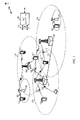
[0037]最初に図1を参照すると、図に、ワイヤレス通信システム100の一例が示されている。システム100は、基地局(またはセル)105と、通信デバイス115と、コアネットワーク130とを含む。基地局105は、様々な実施形態ではコアネットワーク130または基地局105の一部であり得る、基地局コントローラの制御下で通信デバイス115と通信し得る。基地局105は、バックホールリンク132を介して制御情報および/またはユーザデータをコアネットワーク130と通信し得る。いくつかの実施形態では、基地局105は、ワイヤードまたはワイヤレス通信リンクであり得るバックホールリンク134を介して、直接的あるいは間接的に互いに通信し得る。システム100は、複数のキャリア(異なる周波数の波形信号)上での動作をサポートし得る。マルチキャリア送信機は、複数のキャリア上で同時に変調された信号を送信し得る。たとえば、各通信リンク125は、様々な無線技術に従って変調されたマルチキャリア信号であり得る。各変調された信号は、異なるキャリア上で送られ得、制御情報(たとえば、基準信号、制御チャネルなど)、オーバーヘッド情報、データなどを搬送し得る。
[0037] Referring initially to FIG. 1, an example of a
[0038]基地局105は、1つまたは複数の基地局アンテナを介してデバイス115とワイヤレス通信し得る。基地局105サイトの各々は、それぞれの地理的エリア110に対する通信カバレージを与え得る。いくつかの実施形態では、基地局105は、トランシーバ基地局、無線基地局、アクセスポイント、無線トランシーバ、基本サービスセット(BSS)、拡張サービスセット(ESS)、ノードB、発展型ノードB(eノードBまたはeNB)、ホームノードB、ホームeノードB、あるいは何らかの他の好適な用語で呼ばれることがある。基地局のためのカバレージエリア110は、カバレージエリアの一部分のみを構成するセクタに分割され得る。システム100は、異なるタイプの基地局105(たとえば、マクロ基地局、マイクロ基地局、および/またはピコ基地局)を含み得る。異なる技術のための重複するカバレージエリアがあり得る。
[0038]
[0039]いくつかの実施形態では、システム100はLTE/LTE−Aネットワークであり得る。LTE/LTE−Aネットワークでは、発展型ノードB(eNB)およびユーザ機器(UE)という用語は、概して、それぞれ基地局105およびデバイス115について説明するために使用され得る。システム100は、異なるタイプのeNBがその中で様々な地理的領域に対するカバレージを与える、異機種(Heterogeneous)LTE/LTE−Aネットワークであり得る。たとえば、各eNB105は、マクロセル、ピコセル、フェムトセル、および/または他のタイプのセルに対する通信カバレージを与え得る。マクロセルは、概して、比較的大きい地理的エリア(たとえば、半径数キロメートル)をカバーし、ネットワークプロバイダのサービスに加入しているUEによる無制限アクセスを可能にし得る。ピコセルは、概して、比較的小さい地理的エリアをカバーすることになり、ネットワークプロバイダのサービスに加入しているUEによる無制限アクセス(unrestricted access)を可能にし得る。また、フェムトセルは、概して、比較的小さい地理的エリア(たとえば、自宅)をカバーすることになり、無制限アクセスに加えて、フェムトセルとの関連を有するUE(たとえば、限定された加入者グループ(CSG:closed subscriber group)中のUE、自宅内のユーザのためのUEなど)による制限されたアクセス(restricted access)をも可能にし得る。マクロセルのためのeNBはマクロeNBと呼ばれることがある。ピコセルのためのeNBはピコeNBと呼ばれることがある。また、フェムトセルのためのeNBはフェムトeNBまたはホームeNBと呼ばれることがある。eNBは、1つまたは複数の(たとえば、2つ、3つ、4つなどの)セルをサポートし得る。いくつかの構成では、eNB105は、異なるサブフレーム上の複数のCRS送信間の位相不連続性を導入し得る。たとえば、eNB105は、第1の共通基準信号(CRS)送信と第2のCRS送信との間で使用する位相不連続性を決定し得る。eNB105は、次いで、位相連続性を維持することなしに第1のCRS送信および第2のCRS送信などの複数の共通基準信号を送信し得る。これは、決定された位相不連続性を利用することを伴い得る。場合によっては、eNB105は、CRS送信に関してニューキャリアタイプ(NCT)を利用し得る。
[0039] In some embodiments, the
[0040]いくつかの構成では、eNB105は、特定の形態のCRSシーケンス初期化に関与し得る。たとえば、eNB105は、識別された基準信号シーケンス周期に関して、拡張された共通基準信号シーケンス周期(an extended common reference signal sequence period)を決定し得る。一例では、eNB105は、CRSシーケンス周期を10msから、限定はしないが、40msまたは50msを含むより高い値に拡張し得る。これは、たとえば、NCTに有用であり得る。eNB105は、拡張された共通基準信号シーケンス周期を様々な方法で利用し得る。
[0040] In some configurations, the
[0041]コアネットワーク130は、バックホール132(たとえば、S1など)を介してeNB105と通信し得る。eNB105はまた、たとえば、バックホールリンク134(たとえば、X2など)を介しておよび/またはバックホールリンク132を介して(たとえば、コアネットワーク130を通して)、直接的または間接的に、互いに通信し得る。ワイヤレスシステム100は同期動作または非同期動作をサポートし得る。同期動作の場合、eNBは同様のフレームタイミングを有し得、異なるeNBからの送信は近似的に時間的に整合され得る。非同期動作の場合、eNBは異なるフレームタイミングを有し得、異なるeNBからの送信は時間的に整合されないことがある。本明細書で説明する技法は、同期動作または非同期動作のいずれかのために使用され得る。
[0041]
[0042]UE115は、ワイヤレスシステム100全体にわたって分散され得、各UEは固定または移動性であり得る。UE115は、当業者によって、移動局、加入者局、モバイルユニット、加入者ユニット、ワイヤレスユニット、リモートユニット、モバイルデバイス、ワイヤレスデバイス、ワイヤレス通信デバイス、リモートデバイス、モバイル加入者局、アクセス端末、モバイル端末、ワイヤレス端末、リモート端末、ハンドセット、ユーザエージェント、モバイルクライアント、クライアント、または何らかの他の好適な用語で呼ばれることもある。UE115は、セルラーフォン、携帯情報端末(PDA)、ワイヤレスモデム、ワイヤレス通信デバイス、ハンドヘルドデバイス、タブレットコンピュータ、ラップトップコンピュータ、コードレスフォン、ワイヤレスローカルループ(WLL)局などであり得る。UE115は、マクロeNB、ピコeNB、フェムトeNB、リレーなどと通信することが可能であり得る。いくつかの構成では、UE115は、第1のCRS送信および第2のCRS送信など、複数の共通基準信号(CRS)送信間で位相連続性が仮定され得ないと決定する。場合によっては、これは、位相不連続性が使用されるとUE115において決定することを伴い得る。UE115は、位相連続性を維持することなしに、第1のCRS送信および第2のCRS送信など、複数のCRS送信を受信し得る。UE115は、いくつかの構成では、CRS送信に関してニューキャリアタイプ(NCT)を使用し得る。場合によっては、共通基準シグナリングはセル固有基準シグナリング(cell-specific reference signaling)と呼ばれることがある。
[0042] The
[0043]いくつかの構成では、UE115はCRSシーケンス初期化に関して利用され得る。たとえば、UE115は、識別された基準信号シーケンス周期に関して、拡張された共通基準信号シーケンス周期を決定し得る。UE115は、拡張された共通基準信号シーケンス周期を様々な方法で利用し得る。UE115は、いくつかの構成では、CRSシーケンス初期化に関してニューキャリアタイプ(NCT)を使用し得る。
[0043] In some configurations, the
[0044]ネットワーク100中に示された送信リンク125は、モバイルデバイス115から基地局105へのアップリンク送信、および/または基地局105からモバイルデバイス115へのダウンリンク送信を含み得る。ダウンリンク送信は順方向リンク送信と呼ばれることもあり、アップリンク送信は逆方向リンク送信と呼ばれることもある。ワイヤレスシステム100についてLTE/LTEアドバンストアーキテクチャに関して説明したが、本開示全体にわたって提示される様々な概念は他のタイプのワイヤレスネットワークに拡張され得ることを、当業者は容易に諒解されよう。
[0044] The
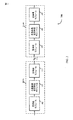
[0045]図2に、開示する実施形態に従って使用され得るシステム200を示す。システム200は、1つまたは複数のコンポーネントキャリア1〜N(CC1〜CCN)を使用してeNB105−a(たとえば、基地局、アクセスポイントなど)と通信し得る、UE115−aを含み得る。UE115−aおよびeNB105−aは、図1のUE115およびeNB105の例であり得る。図2にはただ1つのユーザ機器115−aおよび1つのeNB105−aが示されているが、システム200は任意の数のUE115および/またはeNB105を含み得ることを諒解されたい。
[0045] FIG. 2 illustrates a
[0046]一実施形態では、eNB105−aは、コンポーネントキャリアCC1205〜CCN210上の順方向(ダウンリンク)チャネル220および230を介してUE115−aに情報を送信し得る。さらに、UE115−aは、コンポーネントキャリアCC1205〜CCN210上の逆方向(アップリンク)チャネル215および225を介してeNB105−aに情報を送信し得る。図2ならびに開示される実施形態のいくつかに関連する他の図の様々なエンティティについて説明する際は、説明の目的で、3GPP LTEまたはLTE−Aワイヤレスネットワークに関連する用語が使用される。ただし、システム200は、限定はしないが、OFDMAワイヤレスネットワーク、CDMAネットワーク、3GPP2 CDMA2000ネットワークなどの他のネットワークにおいて動作し得ることを諒解されたい。
[0046] In one embodiment, the eNB 105-a may transmit information to the UE 115-a via forward (downlink)
[0047]LTE−Aベースのシステムでは、UE115−aは、より広い全送信帯域幅を可能にするためにeNB105−aによって利用される複数のコンポーネントキャリアで構成され得る(たとえば、キャリアアグリゲーション)。図2に示されているように、UE115−aは「コンポーネントキャリア1」205〜「コンポーネントキャリアN」210で構成され得、ここで、Nは1以上の整数である。図2は2つのコンポーネントキャリアを示しているが、UE115−aは、任意の好適な数のコンポーネントキャリアで構成され得、したがって、本明細書で開示される主題および特許請求の範囲は2つのコンポーネントキャリアに限定されないことを諒解されたい。コンポーネントキャリア205〜210は、それぞれのダウンリンク220および230ならびにそれぞれのアップリンク215および225を含み得る。
[0047] In an LTE-A based system, the UE 115-a may be configured with multiple component carriers utilized by the eNB 105-a to allow for a wider overall transmission bandwidth (eg, carrier aggregation). As shown in FIG. 2, the UE 115-a may be configured with “
[0048]マルチキャリア動作中、異なるUEに関連付けられたダウンリンク制御情報(DCI:Downlink Control Information)メッセージは、複数のコンポーネントキャリア上で搬送され得る。たとえば、PDCCH上のDCIは、PDSCH送信のためにUEによって使用されるように構成された同じコンポーネントキャリア上に含まれ得る(すなわち、同一キャリアシグナリング(same-carrier signaling))。代替または追加として、DCIは、PDSCH送信のために使用されるターゲットコンポーネントキャリアとは異なるコンポーネントキャリア上で搬送され得る(たとえば、クロスキャリアシグナリング(cross-carrier signaling))。いくつかの実施形態では、半静的に有効化され得るキャリアインジケータフィールド(CIF:carrier indicator field)は、PDSCH送信のためのターゲットキャリア以外のキャリアからのPDCCH制御シグナリングの送信を容易にするために、一部または全部のDCIフォーマット中に含まれ得る(クロスキャリアシグナリング)。 [0048] During multi-carrier operation, Downlink Control Information (DCI) messages associated with different UEs may be carried on multiple component carriers. For example, DCI on the PDCCH may be included on the same component carrier configured to be used by the UE for PDSCH transmission (ie, same-carrier signaling). Alternatively or additionally, DCI may be carried on a different component carrier than the target component carrier used for PDSCH transmission (eg, cross-carrier signaling). In some embodiments, a carrier indicator field (CIF) that may be semi-statically enabled may facilitate transmission of PDCCH control signaling from a carrier other than the target carrier for PDSCH transmission. , May be included in some or all DCI formats (cross-carrier signaling).
[0049]LTE/LTE−Aベースのシステムへの拡張は、これらのシステムの容量およびカバレージを増加させ得る。さらに、LTE/LTE−Aベースのシステムへの拡張が実装されたとき、異なるセル間の協調も改善し得る。一実施形態では、システムの容量およびカバレージを増加させるためにキャリアアグリゲーションに基づく小さいセル拡張が実装され得る。 [0049] Extensions to LTE / LTE-A based systems may increase the capacity and coverage of these systems. Furthermore, cooperation between different cells may also be improved when extensions to LTE / LTE-A based systems are implemented. In one embodiment, small cell expansion based on carrier aggregation may be implemented to increase system capacity and coverage.
[0050]ニューキャリアタイプ(NCT)は、小さいセルを最適化するのを助けるために導入され得る。NCTはマクロセルにおいても使用され得る。一構成では、NCTは、共通基準信号オーバーヘッドを低減し、ダウンリンク制御チャネルの動作が復調基準信号(demodulation reference signals)に基づくことを可能にし得る。たとえば、LTE/LTE−A Rel.12では、NCTが導入され、セル固有基準信号の送信が5つのサブフレームのうち4つにおいて除去される。これは、eNBの異なる送信アンテナ構成に対する様々な性能利得を与え得る。しかしながら、CRS周期性を低減すると異なる問題が生じ得る。様々な構成がこれらの問題に対処し得る。たとえば、いくつかの構成では、異なるサブフレーム上の複数のCRS送信間の位相不連続性が導入され得る。場合によっては、NCT上でeNB105−aからUE115−aに送信されるインジケータは、位相連続性が仮定され得るか否かを示し得る。さらに、低減されたCRS周期性では、セルによって送信されるCRSシーケンスがより少数であり得る。これはCRSシーケンス初期化に影響を及ぼし得る。いくつかの構成は、セルごとの可能なシーケンスの数が(たとえば、(10msCRSシーケンス初期化周期性のための)2から(40msCRSシーケンス初期化周期性のための)8に)増加され得るように、拡張されたCRSシーケンス周期性を利用することによってこの問題に対処し得る。いくつかの構成はまた、時間および/または周波数マッピング、eNB105−aからUE115−aへの送信など、CRS構成情報を導入し得る。CRS構成情報はシステム帯域幅に依存し得る。 [0050] A new carrier type (NCT) may be introduced to help optimize small cells. NCT can also be used in macrocells. In one configuration, NCT may reduce common reference signal overhead and allow downlink control channel operation to be based on demodulation reference signals. For example, LTE / LTE-A Rel. At 12, NCT is introduced and cell specific reference signal transmissions are removed in four of the five subframes. This can provide various performance gains for different transmit antenna configurations of the eNB. However, reducing CRS periodicity can create different problems. Various configurations can address these issues. For example, in some configurations, phase discontinuities between multiple CRS transmissions on different subframes may be introduced. In some cases, an indicator transmitted from eNB 105-a to UE 115-a on the NCT may indicate whether phase continuity may be assumed. Further, with reduced CRS periodicity, fewer CRS sequences may be transmitted by the cell. This can affect CRS sequence initialization. Some configurations allow the number of possible sequences per cell to be increased (eg, from 2 (for 10 ms CRS sequence initialization periodicity) to 8 (for 40 ms CRS sequence initialization periodicity)). This problem can be addressed by taking advantage of the extended CRS sequence periodicity. Some configurations may also introduce CRS configuration information, such as time and / or frequency mapping, transmission from eNB 105-a to UE 115-a. CRS configuration information may depend on system bandwidth.
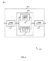
[0051]図3は、様々な構成によるワイヤレス通信システム300を示すブロック図300である。システム300は、様々な構成によるUE115−bと基地局105−bとを含む。UE115−bは、図1、図2、および/または図8に示されたUE115の一例であり得る。基地局105−bは、図1、図2、および/または図8に示された基地局の一例であり得る。基地局105−bは、受信機モジュール305、共通基準信号管理モジュール310、および/または送信機モジュール315を含み得る。これらの構成要素の各々は互いに通信中であり得、場合によっては、これらの構成要素は1つまたは複数のモジュールに組み込まれ得る。UE115−bは、受信機モジュール355と、共通基準信号処理モジュール360と、送信機モジュール365とを含み得る。これらの構成要素の各々は互いに通信中であり得、これらの構成要素は1つまたは複数のモジュールに組み込まれ得る。基地局115−bおよびUE115−bは互いにワイヤレス通信325中であり得る。
[0051] FIG. 3 is a block diagram 300 illustrating a
[0052]UE115−bまたは基地局105−bのこれらの構成要素は、ハードウェア中の適用可能な機能の一部または全部を実行するように適応された1つまたは複数の特定用途向け集積回路(ASIC)を用いて個別にまたは集合的に実装され得る。代替的に、機能は、1つまたは複数の他の処理ユニット(またはコア)によって、1つまたは複数の集積回路上で実行され得る。他の実施形態では、当技術分野で知られている任意の方法でプログラムされ得る他のタイプの集積回路(たとえば、ストラクチャード/プラットフォームASIC、フィールドプログラマブルゲートアレイ(FPGA)、および他のセミカスタムIC)が使用され得る。各ユニットの機能はまた、1つまたは複数の汎用または特定用途向けプロセッサによって実行されるためにフォーマットされた、メモリ中に組み込まれた命令を用いて全体的にまたは部分的に実装され得る。 [0052] These components of the UE 115-b or the base station 105-b are one or more application specific integrated circuits adapted to perform some or all of the applicable functions in hardware. It can be implemented individually or collectively using (ASIC). Alternatively, the functions may be performed on one or more integrated circuits by one or more other processing units (or cores). In other embodiments, other types of integrated circuits (eg, structured / platform ASICs, field programmable gate arrays (FPGAs), and other semi-custom ICs) that can be programmed in any manner known in the art. Can be used. The functionality of each unit may also be implemented in whole or in part using instructions embedded in memory that are formatted to be executed by one or more general purpose or application specific processors.
[0053]いくつかの構成では、UE115−bの受信機モジュール355は、セルラー受信機を含み得、送信機モジュール315から送信された基地局105−bからの送信を受信し得る。基地局105−bの共通基準信号(CRS)管理モジュール310は、送信機モジュール315を介して送信され得るCRS送信を管理し得る。UE115−bのCRS処理モジュール360は、受信機モジュール355を介して受信され得るCRS送信を処理し得る。
[0053] In some configurations, the
[0054]いくつかの構成では、CRS管理モジュール310は、異なるサブフレーム上の複数のCRS送信間の位相不連続性を導入し得る。たとえば、CRS管理モジュール310は、第1の共通基準信号(CRS)送信と第2のCRS送信との間で使用する位相不連続性を決定し得る。CRS管理モジュール310および/または送信機モジュール315は、次いで、位相連続性を維持することなしに第1のCRS送信と第2のCRS送信とを送信し得る。これは、決定された位相不連続性を利用することを伴い得る。UE115−bは、第1の共通基準信号(CRS)送信と第2のCRS送信との間で位相連続性が仮定され得ないと決定するためにCRS処理モジュール360を利用し得る。場合によっては、これは、位相不連続性が使用されると決定することを伴い得る。CRS処理モジュール360および/または受信機モジュール355は、位相不連続性を使用する第1のCRS送信と第2のCRS送信とを受信し得る。システム300はCRS送信に関してニューキャリアタイプ(NCT)を使用し得る。
[0054] In some configurations, the
[0055]いくつかの構成では、基地局105−bのCRS管理モジュール310および/またはUE115−bのCRS処理モジュール360がCRSシーケンス初期化に関して利用され得る。たとえば、CRS管理モジュール310および/またはCRS処理モジュール360は、識別された基準信号シーケンス周期に関して、拡張された共通基準信号シーケンス周期を決定し得る。CRS管理モジュール310および/またはCRS処理モジュール360は、拡張された共通基準信号シーケンス周期を様々な方法で利用し得る。ワイヤレス通信システム300は、CRSシーケンス初期化に関してニューキャリアタイプ(NCT)を使用し得る。
[0055] In some configurations, the
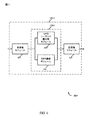
[0056]次に図4および図5を参照すると、図4は、様々な構成による基地局105−cを示すブロック図400を示し、図5は、様々な構成によるUE115−cのブロック図500を示している。UE115−cは、図1、図2、図3、および/または図8に示されたUE115の一例であり得る。基地局105−cは、図1、図2、図3および/または図8に示された基地局の一例であり得る。基地局105−cおよびUE115−cは、本明細書で説明される機能を実行するための手段であるか、またはそれを含み得る。基地局105−cは、受信機モジュール305、共通基準信号(CRS)管理モジュール310−a、および/または送信機モジュール315を含み得る。CRS管理モジュール310−aは、CRS位相不連続性モジュール405および/またはCRS位相状態インジケータモジュール410を含み得る。CRS管理モジュール310−aは図3および/または図8のCRS管理モジュール310の一例であり得る。基地局105−cの構成要素の各々は互いに通信中であり得、場合によっては、これらの構成要素は1つまたは複数のモジュールに組み込まれ得る。UE115−cは、受信機モジュール355と、共通基準信号(CRS)処理モジュール360−aと、送信機モジュール365とを含み得る。CRS処理モジュール360−aは、CRS位相状態決定モジュール510および/またはCRSコヒーレントコンバイナモジュール(a CRS coherent combiner module)505を含み得る。CRS処理モジュール360−aは図3および/または図8のCRS管理モジュール360の一例であり得る。UE115−cの構成要素の各々は互いに通信中であり得、これらの構成要素は1つまたは複数のモジュールに組み込まれ得る。
[0056] Referring now to FIGS. 4 and 5, FIG. 4 shows a block diagram 400 illustrating a base station 105-c according to various configurations, and FIG. 5 is a block diagram 500 of a UE 115-c according to various configurations. Is shown. UE 115-c may be an example of
[0057]UE115−cまたは基地局105−cのこれらの構成要素は、ハードウェア中の適用可能な機能の一部または全部を実行するように適応された1つまたは複数の特定用途向け集積回路(ASIC)を用いて個別にまたは集合的に実装され得る。代替的に、機能は、1つまたは複数の他の処理ユニット(またはコア)によって、1つまたは複数の集積回路上で実行され得る。他の実施形態では、当技術分野で知られている任意の方法でプログラムされ得る他のタイプの集積回路(たとえば、ストラクチャード/プラットフォームASIC、フィールドプログラマブルゲートアレイ(FPGA)、および他のセミカスタムIC)が使用され得る。各ユニットの機能はまた、1つまたは複数の汎用または特定用途向けプロセッサによって実行されるためにフォーマットされた、メモリ中に組み込まれた命令を用いて全体的にまたは部分的に実装され得る。 [0057] These components of the UE 115-c or the base station 105-c are one or more application specific integrated circuits adapted to perform some or all of the applicable functions in hardware. It can be implemented individually or collectively using (ASIC). Alternatively, the functions may be performed on one or more integrated circuits by one or more other processing units (or cores). In other embodiments, other types of integrated circuits (eg, structured / platform ASICs, field programmable gate arrays (FPGAs), and other semi-custom ICs) that can be programmed in any manner known in the art. Can be used. The functionality of each unit may also be implemented in whole or in part using instructions embedded in memory that are formatted to be executed by one or more general purpose or application specific processors.
[0058]いくつかの構成では、UE115−cの受信機モジュール355は、セルラー受信機を含み得、送信機モジュール315から送信された基地局105−cなどの基地局からの送信を受信し得る。基地局105−cの共通基準信号(CRS)管理モジュール310−aは、送信機モジュール315を介して送信され得るCRS送信を管理し得る。UE115−cのCRS処理モジュール360−aは、受信機モジュール355を介して受信され得るCRS送信を処理し得る。
[0058] In some configurations, the
[0059]いくつかの構成では、CRS管理モジュール310は、異なるサブフレーム上の複数のCRS送信間の位相不連続性を導入し得る。たとえば、CRS管理モジュール310は、第1の共通基準信号(CRS)送信と第2のCRS送信との間で使用する位相不連続性を決定し得る。CRS管理モジュール310および/または送信機モジュール315は、次いで、位相連続性を維持することなしに第1のCRS送信と第2のCRS送信とを送信し得る。これは、位相不連続性を使用することを伴い得る。
[0059] In some configurations, the
[0060]異なるサブフレーム上のCRS間の位相不連続性を導入することは、1つのサブフレーム上の起こり得る信号ヌルが後続のサブフレーム上でおそらく生じ得ないようにさせ得る。その結果、異なるサブフレームにわたる信号の非コヒーレント結合(non-coherent combining)の場合と同様にCRSカバレージホールが最小限に抑えられ得、カバレージホールの確率が著しく低減され得る。 [0060] Introducing a phase discontinuity between CRSs on different subframes may cause a possible signal null on one subframe to probably not occur on subsequent subframes. As a result, CRS coverage holes can be minimized as in the case of non-coherent combining of signals across different subframes, and the probability of coverage holes can be significantly reduced.
[0061]UE115−cについて、コヒーレント結合が、あるサブフレームで可能にされ得、CRSコヒーレントコンバイナモジュール505を利用して実装され得る。たとえば、2つの異なるOFDMシンボル上の物理リソースブロック(PRB:physical resource block)ごとの4つのCRSトーンが利用され得る。同じサブフレームに属する2つのOFDMシンボル間で位相連続性が維持され得る。しかしながら、1つのサブフレーム上のCRSは、場合によっては、後続のサブフレーム上のCRSのための基準として(as a reference for CRS)使用されないことがある。
[0061] For UE 115-c, coherent combining may be enabled in certain subframes and may be implemented utilizing CRS
[0062]UE115−cは、たとえば、第1の共通基準信号(CRS)送信と第2のCRS送信との間で、位相連続性が使用されると仮定され得ないことを決定するために、CRS位相状態決定モジュール510を介してCRS処理モジュール360−aを利用し得る。これは、位相不連続性が使用されると決定することを伴い得る。CRS位相ステートメント決定モジュール510を介したCRS処理モジュール360−a、および/または受信機モジュール355は、位相連続性を維持することなしに第1のCRS送信と第2のCRS送信とを受信し得る。場合によっては、これは、位相不連続性を使用する複数の共通基準信号を伴い得る。
[0062] The UE 115-c may, for example, determine that phase continuity cannot be assumed to be used between the first common reference signal (CRS) transmission and the second CRS transmission. The CRS processing module 360-a may be utilized via the CRS phase
[0063]場合によっては、基地局105−cは、UE115−cなどのUEが異なるサブフレームにわたるCRSトーン上の信号をコヒーレントに結合し得るかどうかを、そのUEに示し得る。いくつかの構成は、標準によって規定され得る静的指示を利用し得る。たとえば、標準的な構成は、基地局105−cおよび/またはUE115−cの両方に対して、サブフレーム間の位相不連続性が利用されない、連続CRS位相が概して利用され得る、と仮定することであり得る。次いで、連続CRS位相モードからCRS位相不連続性モードへの、またはその逆の変化を示すためのシグナリングが利用され得る。他の構成は、UEへの半静的指示を利用し得る。たとえば、RRCシグナリングは、ユニキャストされ得る専用シグナリングのために利用され、および/または複数のSIBのうちの1つ中でブロードキャストし得るシステム情報を通して利用され得る。システム情報変化プロシージャは、たとえば、位相情報が変化したときに呼び出され得る。この情報は頻繁に変化しないことが予想され得るが、たとえば、異なるセルタイプ、および/またはニューキャリアタイプ(NCT)を検出し測定し得るレガシーUEへの潜在的影響にアクセスするための何らかの最適化が利用され得る。本明細書で使用する「レガシーUE」は、NCTに先行する(pre-date NCT)キャリアタイプおよび/またはシングルキャリアを採用するシステム上での動作のために構成または最適化されたUEを指すことがある。たとえば、レガシーUEは、LTE/LTE−A Rel.12に先行するLTE/LTE−Aネットワーク上での使用のために構成されたUEであり得る。いくつかの実装形態では、たとえば、ネットワーク上で登録されたレガシーUEがある場合、CRS位相不連続性は使用されないが、ネットワーク上で登録されたレガシーUEがない場合、CRS位相不連続性が使用され得、基地局105−cによってCRS位相不連続性の指示がUEにシグナリングされ得る。 [0063] In some cases, base station 105-c may indicate to a UE such as UE 115-c whether it can coherently combine signals on CRS tones across different subframes. Some configurations may utilize static instructions that may be defined by standards. For example, the standard configuration assumes that for both base stations 105-c and / or UE 115-c, continuous CRS phases can generally be utilized, where phase discontinuities between subframes are not utilized. It can be. Signaling may then be utilized to indicate a change from continuous CRS phase mode to CRS phase discontinuity mode or vice versa. Other configurations may utilize a semi-static indication to the UE. For example, RRC signaling may be utilized for dedicated signaling that may be unicast and / or utilized through system information that may be broadcast in one of multiple SIBs. The system information change procedure can be invoked, for example, when the phase information changes. Although this information may be expected to not change frequently, for example, some optimization to access potential impacts on legacy UEs that may detect and measure different cell types and / or new carrier types (NCT), for example Can be used. As used herein, “legacy UE” refers to a UE configured or optimized for operation on a system that employs a pre-date NCT carrier type and / or a single carrier. There is. For example, the legacy UE is LTE / LTE-A Rel. 12 may be a UE configured for use on an LTE / LTE-A network preceding 12. In some implementations, for example, if there are legacy UEs registered on the network, the CRS phase discontinuity is not used, but if there are no legacy UEs registered on the network, the CRS phase discontinuity is used. An indication of CRS phase discontinuity may be signaled to the UE by the base station 105-c.
[0064]いくつかの構成は、CRS位相連続性の変化を示すために基地局105−cのCRS位相状態インジケータモジュール410を利用することを含む。たとえば、CRS位相状態インジケータモジュールは、それが、異なるサブフレーム上の複数のCRS送信間の位相不連続性を利用することからコヒーレント位相に変化している、ことを示し得る。場合によっては、CRS位相状態インジケータモジュールは、位相連続性が仮定され得ることを示し得る。インジケータはUE115−cのCRS位相状態決定モジュール510によって受信され得、したがって、CRS位相状態決定モジュール510は変化を決定し得、次いで場合によっては、CRS信号をコヒーレント結合することを開始し得る。
[0064] Some configurations include utilizing the CRS phase
[0065]適切なUE測定を保証するために、シグナリングがCRS位相連続性の変化を示すときはいつでも、基地局115−cは位相連続性を維持し得る。たとえば、t_0において、CRS位相が連続でないことがあり、この場合、UEは、サブフレームにわたってCRS信号をコヒーレントに結合しないことがある。t_1において、基地局115−cが連続CRS位相に切り替わり得、場合によっては、基地局115−cは、この変化を容易にするためにCRS位相不連続性モジュール405を利用し得る。t_2において、基地局105−cは、連続CRS位相へのCRS位相の変化を示し得、基地局105−cは、このプロセスを容易にするためにCRS位相状態インジケータモジュール410を利用し得る。t_3において、UE115−cなどのUEは、変化を示しCRS信号のコヒーレント結合から開始するシグナリングを処理し得、UE115−cは、このプロセスを容易にするためにCRS位相状態決定モジュール510および/またはCRSコヒーレントコンバインモジュール505を利用し得る。
[0065] To ensure proper UE measurements, base station 115-c may maintain phase continuity whenever signaling indicates a change in CRS phase continuity. For example, at t_0, the CRS phase may not be continuous, in which case the UE may not coherently combine the CRS signals across subframes. At t_1, base station 115-c may switch to a continuous CRS phase, and in some cases, base station 115-c may utilize CRS
[0066]基地局105−cはまた、CRS位相不連続性モジュール405および/またはCRS位相状態インジケータモジュール410を利用して不連続CRS位相(a discontinuous CRS phase)を利用するために変化を示し得る。たとえば、t_0において、基地局105−cは、連続であるCRS位相を利用し得る。これらの場合、UE115−cなどのUEは、CRSコヒーレントコンバイナモジュール505を介して、サブフレームにわたってCRS信号をコヒーレントに結合し得る。t_1において、基地局105−cは、CRS位相状態インジケータモジュール410を介して、それが連続CRS位相を利用することから不連続CRS位相を利用することに変化しようとしていることを示し得る。t_2において、UE115−cなどのUEは、CRS位相状態決定モジュール510を介して、変化を示すシグナリングを処理し得、CRS信号のコヒーレント結合で停止し得る。t_3において、基地局105−cは、CRS位相不連続性モジュール405を使用して不連続CRS位相を利用することに切り替わり得る。場合によっては、基地局105−cは、それがUEにCRS位相変化を示すインジケータを送信する前に、不連続CRS位相を利用することに切り替わり得る。
[0066] Base station 105-c may also indicate a change to utilize a discontinuous CRS phase utilizing CRS
[0067]概していくつかの構成では、基地局105−cは、CRS位相状態インジケータモジュールおよび/または送信機モジュール315を介して、位相連続性が仮定され得ないことを示すインジケータを(UE115−cなどの)1つまたは複数のUEに送信し得る。これは、決定された位相不連続性が使用されるべきであるというインジケータを送信することを伴い得る。インジケータは、位相連続性なしでまたは位相不連続性を使用して第1のCRS送信と第2のCRS送信とが送信される前に、1つまたは複数のUEに送信され得る。
[0067] Generally, in some configurations, base station 105-c may provide an indicator (UE 115-c) via CRS phase state indicator module and / or
[0068]場合によっては、基地局105−cは、CRS位相状態インジケータモジュール410を利用して第3のCRS送信と第4のCRS送信との間で連続CRS位相が使用されるべきであると決定し得る。第3のCRS送信と第4のCRS送信とは、連続CRS位相を使用して送信され得る。位相連続性が仮定され得ること、または決定された位相不連続性の使用が中止されるべきであることを示すインジケータが、CRS位相状態インジケータモジュール410を利用して1つまたは複数のUEに送信され得る。いくつかの構成は、第3のCRS送信と第4のCRS送信とがコヒーレントに結合され得ることを示すインジケータをCRS位相状態インジケータモジュール410を介して1つまたは複数のUEに送信することを含む。
[0068] In some cases, the base station 105-c may utilize the CRS phase
[0069]UE側では、UE115−cなどのUEは、基地局105−cなどの基地局から受信機355を介して共通基準信号を受信するように構成され得る。概してCRS位相状態決定モジュール310を利用して、UE115−cは、第1の共通基準信号(CRS)送信と第2のCRS送信との間で、位相連続性が仮定され得ないと、または位相不連続性が使用されると決定し得る。UE115−cは、受信機モジュール355および/またはCRS位相状態決定モジュール510を利用して位相連続性を維持することなしに第1のCRS送信と第2のCRS送信とを受信し得る。これは位相不連続性の使用を伴い得る。
[0069] On the UE side, a UE such as UE 115-c may be configured to receive a common reference signal via a
[0070]場合によっては、第1のCRS送信と第2のCRS送信との間で、位相連続性が仮定され得ないと、または位相不連続性が使用されると決定することは、位相連続性が仮定され得ないこと、または位相不連続性が使用されるようになることを示すインジケータをCRS位相状態決定モジュール510において受信することを含み得る。場合によっては、連続CRS位相を使用する第3のCRS送信と第4のCRS送信とが受信され得る。位相連続性が仮定され得ること、または決定された位相不連続性が中断されたことを示すインジケータがCRS位相状態決定モジュール510において受信され得る。場合によっては、第3のCRS送信と第4のCRS送信とがコヒーレントに結合され得るというインジケータが、CRS位相状態決定モジュール510によって受信され、利用され得る。
[0070] In some cases, determining that phase continuity cannot be assumed or phase discontinuity is used between the first CRS transmission and the second CRS transmission is phase continuity. Receiving an indicator at the CRS phase
[0071]場合によっては、基地局105−cによって利用される位相不連続性は第1のフレームと第2のフレームとの間に生じ得る。たとえば、NCT上のCRSが5msごとに送信され得、CRSのための現在の擬似ランダムシーケンスが概して10msの周期性を有する場合、10ms(1フレーム)持続時間など、各フレーム内でCRS位相連続性を維持することが可能であり得る。追加または代替として、1つまたは複数のフレーム境界において位相不連続性を有することが、可能であり得る。フレーム間で位相不連続性が発生する場合、UE115などのUEは、1つのフレーム中で複数のCRS送信(たとえば、2つのCRS送信)を依然としてコヒーレントに結合し得る。他の場合には、位相不連続性は所与のフレームの複数のサブフレーム間で生じ得る。たとえば、第1のCRS送信と第2のCRS送信とが第1のフレーム内で生じ得る。
[0071] In some cases, the phase discontinuity utilized by base station 105-c may occur between the first frame and the second frame. For example, if a CRS on the NCT may be sent every 5 ms and the current pseudo-random sequence for the CRS generally has a periodicity of 10 ms, the CRS phase continuity within each frame, such as 10 ms (1 frame) duration It may be possible to maintain In addition or alternatively, it may be possible to have a phase discontinuity at one or more frame boundaries. If phase discontinuities occur between frames, a UE such as
[0072]いくつかの構成では、基地局105−cは、CRS位相不連続性モジュール405を介して、位相ランプアップまたはサイクル遅延ダイバーシティ(CDD)プロセスを使用してCRS位相不連続性を導入し得る。たとえば、時間とともに緩やかにチャネルを混乱させるために、時間において変動する循環的遅延(variable cyclical delay in time)と、アンテナにわたるCDDとがあり得る。CDDは周波数におけるものでもあり得る。このようにして、CCDは、時間においてまたは周波数においてCRS位相を変化させて位相不連続性を導入し得る。
[0072] In some configurations, the base station 105-c introduces a CRS phase discontinuity using a phase ramp up or cycle delay diversity (CDD) process via the CRS
[0073]いくつかの構成では、基地局105−cおよび/またはUE115−cは、それらが不連続CRS位相を利用するか連続CRS位相を利用するかにかかわらず、CRS送信を送信および/または受信することに関してニューキャリアタイプ(NCT)を利用し得る。 [0073] In some configurations, base stations 105-c and / or UE 115-c may transmit and / or transmit CRS transmissions regardless of whether they utilize discontinuous CRS phases or continuous CRS phases. New carrier type (NCT) may be utilized for receiving.
[0074]次に図6および図7を参照すると、図6は、様々な構成による基地局105−dを示すブロック図600を示し、図7は、様々な構成によるUE115−dのブロック図700を示している。UE115−dは、図1、図2、図3、および/または図8に示されたUE115の一例であり得る。基地局105−dは、図1、図2、図3および/または図8に示された基地局の一例であり得る。基地局105−dは、受信機モジュール305、共通基準信号(CRS)管理モジュール310−b、および/または送信機モジュール315を含み得る。CRS管理モジュール310−bは、CRSシーケンス周期性モジュール605および/またはCRS構成モジュール610を含み得る。CRS管理モジュール310−bは図3および/または図8のCRS管理モジュール310の一例であり得る。基地局105−dの構成要素の各々は互いに通信中であり得、場合によっては、これらの構成要素は1つまたは複数のモジュールに組み込まれ得る。UE115−dは、受信機モジュール355と、共通基準信号(CRS)処理モジュール360−bと、送信機モジュール365とを含み得る。CRS処理モジュール360−bは、CRSシーケンス境界モジュール(a CRS sequence boundary module)705および/またはCRS構成決定モジュール710を含み得る。CRS処理モジュール360−bは図3および/または図8のCRS管理モジュール360の一例であり得る。UE115−dの構成要素の各々は互いに通信中であり得、これらの構成要素は1つまたは複数のモジュールに組み込まれ得る。
[0074] Referring now to FIGS. 6 and 7, FIG. 6 shows a block diagram 600 illustrating a base station 105-d according to various configurations, and FIG. 7 illustrates a block diagram 700 of a UE 115-d according to various configurations. Is shown. The UE 115-d may be an example of the
[0075]UE115−dまたは基地局105−dのこれらの構成要素は、ハードウェア中の適用可能な機能の一部または全部を実行するように適応された1つまたは複数の特定用途向け集積回路(ASIC)を用いて個別にまたは集合的に実装され得る。代替的に、機能は、1つまたは複数の他の処理ユニット(またはコア)によって、1つまたは複数の集積回路上で実行され得る。他の実施形態では、当技術分野で知られている任意の方法でプログラムされ得る他のタイプの集積回路(たとえば、ストラクチャード/プラットフォームASIC、フィールドプログラマブルゲートアレイ(FPGA)、および他のセミカスタムIC)が使用され得る。各ユニットの機能はまた、1つまたは複数の汎用または特定用途向けプロセッサによって実行されるためにフォーマットされた、メモリ中に組み込まれた命令を用いて個別にまたは集合的に実装され得る。 [0075] These components of UE 115-d or base station 105-d are one or more application specific integrated circuits adapted to perform some or all of the applicable functions in hardware. It can be implemented individually or collectively using (ASIC). Alternatively, the functions may be performed on one or more integrated circuits by one or more other processing units (or cores). In other embodiments, other types of integrated circuits (eg, structured / platform ASICs, field programmable gate arrays (FPGAs), and other semi-custom ICs) that can be programmed in any manner known in the art. Can be used. The functionality of each unit may also be implemented individually or collectively using instructions embedded in memory formatted to be executed by one or more general purpose or application specific processors.
[0076]いくつかの構成では、UE115−dの受信機モジュール335は、セルラー受信機を含み得、送信機モジュール315から送信された基地局105−dなどの基地局からの送信を受信し得る。基地局105−dの共通基準信号(CRS)管理モジュール310−bは、送信機モジュール315を介して送信され得るCRS送信を管理し得る。UE115−dのCRS処理モジュール360−bは、受信機モジュール355を介して受信され得るCRS送信を処理し得る。
[0076] In some configurations, the receiver module 335 of the UE 115-d may include a cellular receiver and may receive transmissions from base stations such as the base station 105-d transmitted from the
[0077]いくつかの構成では、基地局105−dのCRS管理モジュール310−bおよび/またはUE115−dのCRS処理モジュール360−bがCRSシーケンス初期化に関して利用され得る。たとえば、CRS管理モジュール310−bおよび/またはCRS処理モジュール360−bは、識別された基準信号シーケンス周期に関して、拡張された共通基準信号シーケンス周期を決定し得る。CRS管理モジュール310−bおよび/またはCRS処理モジュール360−bは、拡張された共通基準信号シーケンス周期を様々な方法で利用し得る。基地局105−dおよび/またはUE115−dが利用するワイヤレス通信システムは、CRSシーケンス初期化に関してニューキャリアタイプ(NCT)を使用し得る。 [0077] In some configurations, the CRS management module 310-b of the base station 105-d and / or the CRS processing module 360-b of the UE 115-d may be utilized for CRS sequence initialization. For example, CRS management module 310-b and / or CRS processing module 360-b may determine an extended common reference signal sequence period with respect to the identified reference signal sequence period. The CRS management module 310-b and / or the CRS processing module 360-b may utilize the extended common reference signal sequence period in various ways. The wireless communication system utilized by base station 105-d and / or UE 115-d may use a new carrier type (NCT) for CRS sequence initialization.
[0078]たとえば、CRSシーケンス初期化は、場合によっては、10msの周期性などで、特定の周期性で行われ得、たとえば、シーケンスの同じセットが10msごとに繰り返し得る。NCTでは、CRSは、概して、5msの周期性を有し、その結果、(CRSが1msの周期性を有し得る場合のように10個の可能なシーケンスではなく)セルによって送信される2つの可能なCRSシーケンスのみがあり得る。したがって、セルにわたる十分なシーケンスランダム化がないことがあり得る。したがって、測定が影響を受け得る(たとえば、不良なシーケンス相関をもつ2つまたは複数のセルの影響が、測定性能に影響を及ぼし得る)。 [0078] For example, CRS sequence initialization may be performed with a particular periodicity, possibly with a periodicity of 10 ms, for example, the same set of sequences may repeat every 10 ms. In NCT, the CRS generally has a periodicity of 5 ms, so that the two transmitted by the cell (rather than the 10 possible sequences as if the CRS could have a periodicity of 1 ms). There can only be possible CRS sequences. Thus, there may not be sufficient sequence randomization across the cells. Thus, measurements can be affected (eg, the influence of two or more cells with poor sequence correlation can affect measurement performance).
[0079]CRSシーケンス周期性モジュール605を介したCRS管理モジュール310−b、および/またはCRSシーケンス境界モジュール705を介したCRS処理モジュール360−bを利用して提供されるツールおよび技法は、CRSシーケンス周期性を拡張することを通してこれらの問題に対処し得る。たとえば、NCTに関して、NCTにおけるセルごとの可能なシーケンスの数は2よりも大きくなり得る(たとえば、40ms(したがって8つの可能なシーケンス)または50ms(したがって10個の可能なシーケンス))。
[0079] Tools and techniques provided utilizing the CRS management module 310-b via the CRS
[0080]近隣セルを測定するために、UE115−dは、たとえば、CRSシーケンス境界モジュール705を利用して、(サブ)フレーム中で使用される対応するCRSシーケンスを決定し得る。いくつかの一般的な場合では、近隣セルを測定するために、UE115−dなどのUEは、1次同期信号(PSS)および/または2次同期信号(SSS)を検出して、それから、たとえば、セルのための10ms境界と、対応するCRSシーケンスとを導出し得る。拡張されたCRSシーケンス初期化を用いて、UE115−dは、(たとえば、40msを使用して)PSSおよび/またはSSSを検出し、それに物理ブロードキャストチャネル(PBCH)検出が続いて40ms周期の開始を決定し、次いで、CRSシーケンス境界モジュール705を利用して測定のためのCRSシーケンスを導出し得る。場合によっては、UE115−dは、PSSおよび/またはSSSを検出し得、測定のための4つの可能なCRSシーケンスを使用する。
[0080] To measure neighboring cells, UE 115-d may utilize a CRS
[0081]したがって、いくつかの構成では、UE115−dは、特にCRS処理モジュール360−bおよび/またはCRSシーケンス境界モジュール705を介して、拡張された共通基準信号シーケンス周期に関して、拡張されたCRSシーケンス境界をUE115−dにおいて決定し得る。拡張された共通基準信号シーケンス周期に関して、拡張されたCRSシーケンス境界をUE115−dにおいて決定することは、拡張されたCRSシーケンス境界を決定するために、1次同期信号(PSS)と2次同期信号(SSS)と物理ブロードキャストチャネル(PBCH)とを検出することを含み得る。拡張されたCRSシーケンス境界を決定した後に、測定のための1つまたは複数のCRSシーケンスが導出され得る。拡張された共通基準信号シーケンス周期に関してCRSシーケンス境界をUE115−dにおいて決定することは、1次同期信号(PSS)もしくは2次同期信号(SSS)を検出すること、および/または測定のための複数のCRSシーケンス仮定(multiple CRS sequence hypotheses)を利用することを含み得る。
[0081] Thus, in some configurations, the UE 115-d may receive an extended CRS sequence with respect to an extended common reference signal sequence period, particularly via the CRS processing module 360-b and / or the CRS
[0082]場合によっては、基地局105−dは、特にCRS管理モジュール310−bおよび/またはCRSシーケンス周期性モジュール605を介して、1つまたは複数のUE(たとえば、UE115−d)が、拡張されたCRSシーケンス境界を決定することを容易にするために、1次同期信号(PSS)と2次同期信号(SSS)と物理ブロードキャストチャネル(PBCH)とを送信し得る。
[0082] In some cases, base station 105-d may extend one or more UEs (eg, UE 115-d), particularly via CRS management module 310-b and / or CRS
[0083]いくつかの構成では、CRSシーケンス初期化は、CRS構成モジュール610、CRS管理モジュール310−b、および/または送信機モジュール315を利用して、基地局105−dがCRS構成を決定することおよび/または1つまたは複数のUE(たとえば、UE115−d)にCRS構成を送信することを伴い得る。CRS構成はシステム帯域幅に依存し得る。いくつかの構成では、UE115−dは、CRS構成決定モジュール710、CRS処理モジュール360−b、および/または受信機モジュール355を利用してCRS構成を受信および/または決定するように構成され得る。
[0083] In some configurations, CRS sequence initialization utilizes
[0084]たとえば、いくつかの構成は、システム帯域幅に応じてCRS時間および/または周波数マッピングを導入し得る。場合によっては、基地局105−dは、この情報を、拡張物理ブロードキャストチャネル(ePBCH)などの物理ブロードキャストチャネルを通して示し得る。たとえば、小さいシステム帯域幅はより多数のCRSサブフレームを有し得、より大きいシステム帯域幅はより少数のCRSサブフレームを有し得、CRS自体は全体的なまたは部分的な帯域幅にわたり得る。場合によっては、追加の依存性はフレーム構造(FS:Frame Structure)FS1およびFS2、および/またはダウンリンク/アップリンク構成であり得る。たとえば、FS2では、いくつかの構成は2つのDLサブフレームを有し得る。FS1では、マルチキャストブロードキャスト単一周波数ネットワーク(Multicast-Broadcast Single Frequency Network)(MBSFN)は、(たとえば、スタンドアロンNCTについて)MBSFNがどのように定義されるかに応じて、別のファクタであり得る。 [0084] For example, some configurations may introduce CRS time and / or frequency mapping depending on the system bandwidth. In some cases, base station 105-d may indicate this information through a physical broadcast channel, such as an enhanced physical broadcast channel (ePBCH). For example, a small system bandwidth may have a greater number of CRS subframes, a larger system bandwidth may have a smaller number of CRS subframes, and the CRS itself may span the entire or partial bandwidth. In some cases, the additional dependencies may be Frame Structures (FS) FS1 and FS2, and / or downlink / uplink configurations. For example, in FS2, some configurations may have two DL subframes. In FS1, Multicast-Broadcast Single Frequency Network (MBSFN) may be another factor depending on how MBSFN is defined (eg, for standalone NCT).
[0085]図8は、eNB105−eとUE115−eとを含むMIMO通信システム800のブロック図である。このシステム800は図1のシステム100の態様を示し得る。eNB105−eは、図1、図2、図3、図4、および/または図6のeNB105の一例であり得る。UE115−eは、図1、図2、図3、図5、および/または図7のUE115の一例であり得る。eNB105−eはアンテナ834−a〜834−xを装備し得、UE115−eはアンテナ852−a〜852−nを装備し得る。システム800において、eNB105−eは、同時に複数の通信リンク上でデータを送ることが可能であり得る。各通信リンクは「レイヤ」と呼ばれることがあり、通信リンクの「ランク」は、通信のために使用されるレイヤの数を示し得る。たとえば、eNB105−eが2つの「レイヤ」を送信する2×2MIMOシステムでは、eNB105−eとUE115−eとの間の通信リンクのランクは2である。
[0085] FIG. 8 is a block diagram of a
[0086]eNB105−eにおいて、送信プロセッサ820がデータソースからデータを受信し得る。送信プロセッサ820はデータを処理し得る。送信プロセッサ820はまた、基準シンボルとセル固有基準信号とを生成し得る。送信(TX)MIMOプロセッサ830が、適用可能な場合、データシンボル、制御シンボル、および/または基準シンボルに対して空間処理(たとえば、プリコーディング)を実行し得、出力シンボルストリームを送信変調器832−a〜832−xに与え得る。各変調器832は、(たとえば、OFDMなどのために)それぞれの出力シンボルストリームを処理して、出力サンプルストリームを取得し得る。各変調器832はさらに、出力サンプルストリームを処理(たとえば、アナログへの変換、増幅、フィルタ処理、およびアップコンバート)して、ダウンリンク信号を取得し得る。一例では、変調器832−a〜832−xからのダウンリンク信号は、それぞれアンテナ834−a〜834−xを介して送信され得る。受信プロセッサ838は、検出されたシンボルを処理(たとえば、復調、デインターリーブ、および復号)して、UE115−eについて復号されたデータをデータ出力に与え、復号された制御情報をプロセッサ840、またはメモリ842に与え得る。プロセッサ840は送信プロセッサ820および/または送信MIMOプロセッサ830と通信もし得る。いくつかの実施形態では、メモリ842に結合されたプロセッサ840は、本明細書で説明されるシステムおよび方法を実装するために共通基準信号管理モジュール310−cを含み得る。共通基準信号管理モジュール310−cは、図3、図4、および/または図6のモジュール310の例であり得る。
[0086] At eNB 105-e, transmit
[0087]UE115−eにおいて、UEアンテナ852−a〜852−nは、eNB105−eからダウンリンク信号を受信し得、受信信号をそれぞれ復調器854−a〜854−nに与え得る。各復調器854は、それぞれの受信信号を調整(たとえば、フィルタ処理、増幅、ダウンコンバート、およびデジタル化)して、入力サンプルを取得し得る。各復調器854は、(たとえば、OFDMなどのために)入力サンプルをさらに処理して、受信シンボルを取得し得る。MIMO検出器856は、すべての復調器854−a〜854−nから受信シンボルを取得し、適用可能な場合は受信シンボルに対してMIMO検出を実行し、検出されたシンボルを与え得る。受信プロセッサ858は、検出されたシンボルを処理(たとえば、復調、デインターリーブ、および復号)して、UE115−eについて復号されたデータをデータ出力に与え、復号された制御情報をプロセッサ880、またはメモリ882に与え得る。いくつかの実施形態では、プロセッサ880は、本明細書で説明されるシステムおよび方法を実装するために共通基準信号処理モジュール360−cを含み得る。共通基準信号処理モジュール360−cは、図3、図5、および/または図7のモジュール360の例であり得る。
[0087] In UE 115-e, UE antennas 852-a through 852-n may receive downlink signals from eNB 105-e and may provide received signals to demodulators 854-a through 854-n, respectively. Each
[0088]アップリンク上で、UE115−eにおいて、送信プロセッサ864が、データソースからデータを受信し、処理し得る。送信プロセッサ864はまた、基準信号のための基準シンボルを生成し得る。送信プロセッサ864からのシンボルは、適用可能な場合は送信MIMOプロセッサ866によってプリコーディングされ、復調器854−a〜854−nによって(たとえば、SC−FDMAなどのために)さらに処理され、eNB105−eから受信された送信パラメータに従ってeNB105−eに送信され得る。eNB105−eにおいて、UE115−eからのアップリンク信号は、アンテナ834によって受信され、復調器832によって処理され、適用可能な場合はMIMO検出器836によって検出され、受信プロセッサによってさらに処理され得る。受信プロセッサ838は、復号されたデータをデータ出力とプロセッサ840とに与え得る。UE115−eの構成要素は、ハードウェア中の適用可能な機能の一部または全部を実行するように適応された1つまたは複数の特定用途向け集積回路(ASIC)を用いて個別にまたは集合的に実装され得る。言及したモジュールの各々は、システム800の動作に関係する1つまたは複数の機能を実行するための手段であり得る。
[0088] On the uplink, at UE 115-e, a transmit
[0089]同様に、eNB105−eの構成要素は、ハードウェア中の適用可能な機能の一部または全部を実行するように適応された1つまたは複数の特定用途向け集積回路(ASIC)を用いて個別にまたは集合的に実装され得る。言及した構成要素の各々は、システム800の動作に関係する1つまたは複数の機能を実行するための手段であり得る。
[0089] Similarly, components of the eNB 105-e use one or more application specific integrated circuits (ASICs) adapted to perform some or all of the applicable functions in hardware. Can be implemented individually or collectively. Each of the mentioned components may be a means for performing one or more functions related to the operation of
[0090]図9Aは、ワイヤレス通信のための方法900−aの一実施形態を示すフローチャートである。明確にするために、方法900−aについて、図1、図2、図3、図4、および/または図8の基地局105に関して以下で説明する。一実装形態では、図3、図4、および/または図8の共通基準信号管理モジュール310は、以下で説明する機能を実施するために基地局105の機能要素を制御するためのコードの1つまたは複数のセットを実行し得る。
[0090] FIG. 9A is a flowchart illustrating an embodiment of a method 900-a for wireless communication. For clarity, the method 900-a is described below with respect to the
[0091]ブロック905において、第1の共通基準信号(CRS)送信と第2のCRS送信との間で使用する位相不連続性が決定され得る。ブロック910において、位相連続性を維持することなしに第1のCRS送信と第2のCRS送信とが送信され得る。場合によっては、これは、位相不連続性を使用して複数の共通基準信号を送信することを含み得る。
[0091] At
[0092]方法900−aはまた、決定された位相不連続性が使用されるべきであるときなど、その位相連続性が仮定され得ないことを示すインジケータを1つまたは複数のユーザ機器(UE)に送信することを含み得る。最初のインジケータは、位相連続性を維持することなしの第1のCRS送信と第2のCRS送信との前に、1つまたは複数のUEに送信され得る。場合によっては、これは、位相不連続性を使用して複数の共通基準信号を送信することを含み得る。 [0092] Method 900-a may also display an indicator that indicates that phase continuity cannot be assumed, such as when the determined phase discontinuity is to be used, by one or more user equipments (UEs). ) May be included. The first indicator may be sent to one or more UEs before the first CRS transmission and the second CRS transmission without maintaining phase continuity. In some cases, this may include transmitting multiple common reference signals using phase discontinuities.
[0093]場合によっては、第3のCRS送信と第4のCRS送信との間で連続CRS位相が使用されるべきであることが決定され得る。第3のCRS送信と第4のCRS送信とは、連続CRS位相を使用して送信され得る。位相連続性が仮定され得ることを示すインジケータが1つまたは複数のユーザ機器(UE)に送信され得る。場合によっては、インジケータは、決定された位相不連続性が中断されるべきことを示し得る。 [0093] In some cases, it may be determined that a continuous CRS phase should be used between the third CRS transmission and the fourth CRS transmission. The third CRS transmission and the fourth CRS transmission may be transmitted using continuous CRS phases. An indicator may be sent to one or more user equipments (UEs) indicating that phase continuity may be assumed. In some cases, the indicator may indicate that the determined phase discontinuity is to be interrupted.
[0094]方法900−aのいくつかの実施形態は、第3のCRS送信と第4のCRS送信とがコヒーレントに結合され得ることを示すインジケータを1つまたは複数のユーザ機器(UE)に送信することを含む。 [0094] Some embodiments of method 900-a transmit an indicator to one or more user equipments (UEs) indicating that the third CRS transmission and the fourth CRS transmission may be coherently combined. Including doing.
[0095]方法900−aでは、位相不連続性は、場合によっては第1のフレームと第2のフレームとの間で生じ得る。場合によっては、第1のCRS送信と第2のCRS送信とが第1のフレーム内で生じ得る。位相不連続性は、位相ランプアップを使用して導入され得る。場合によっては、位相不連続性は、時間においてまたは周波数においてCRS位相を変化させ得るサイクル遅延ダイバーシティ(CDD)プロセスを使用して導入され得る。 [0095] In method 900-a, a phase discontinuity may possibly occur between the first frame and the second frame. In some cases, a first CRS transmission and a second CRS transmission may occur in the first frame. Phase discontinuities can be introduced using phase ramp-up. In some cases, phase discontinuities may be introduced using a cycle delay diversity (CDD) process that may change the CRS phase in time or in frequency.
[0096]方法900−aのために利用されるワイヤレス通信システムは、第1のCRS送信と第2のCRS送信とのためにニューキャリアタイプ(NCT)を使用し得る。 [0096] The wireless communication system utilized for method 900-a may use a new carrier type (NCT) for the first CRS transmission and the second CRS transmission.
[0097]したがって、方法900−aは、ワイヤレス通信システムにおいて共通基準信号を送信することを提供し得る。方法900−aは一実装形態にすぎないこと、および方法900−aの動作は、他の実装形態が可能であるように、並べ替えられるかまたは場合によっては変更され得ることに留意されたい。 [0097] Accordingly, the method 900-a may provide for transmitting a common reference signal in a wireless communication system. Note that the method 900-a is only one implementation, and the operation of the method 900-a may be reordered or possibly modified, as other implementations are possible.
[0098]図9Bは、ワイヤレス通信のための方法900−bの一実施形態を示すフローチャートである。明確にするために、方法900−bについて、図1、図2、図3、図4、および/または図8の基地局105に関して以下で説明する。一実装形態では、図3、図4、および/または図8の共通基準信号管理モジュール310は、以下で説明される機能を実施するために基地局105の機能要素を制御するためのコードの1つまたは複数のセットを実行し得る。方法900−bは、図9Aの方法900−aの一例であり得る。
[0098] FIG. 9B is a flowchart illustrating an embodiment of a method 900-b for wireless communication. For clarity, the method 900-b is described below with respect to the
[0099]ブロック905−aにおいて、第1の共通基準信号(CRS)送信と第2のCRS送信との間で使用する位相不連続性が決定され得る。ブロック910−aにおいて、位相連続性を維持することなしに第1のCRS送信と第2のCRS送信とが送信され得る。ブロック915において、第3のCRS送信と第4のCRS送信との間で連続CRS位相が使用されるべきであることが決定され得る。ブロック920において、連続CRS位相を使用して、第3のCRS送信と第4のCRS送信とが送信され得る。ブロック925において、位相連続性が仮定され得ることを示すインジケータが1つまたは複数のユーザ機器(UE)に送信され得る。
[0099] At block 905-a, a phase discontinuity to use between a first common reference signal (CRS) transmission and a second CRS transmission may be determined. In block 910-a, a first CRS transmission and a second CRS transmission may be transmitted without maintaining phase continuity. At
[00100]図10Aは、ワイヤレス通信のための方法1000−aの一実施形態を示すフローチャートである。明確にするために、方法1000−aについて、図1、図2、図3、図5、および/または図8のUE115に関して以下で説明する。一実装形態では、図3、図5、および/または図8の共通基準信号処理モジュール360は、以下で説明される機能を実施するためにUE115の機能要素を制御するためのコードの1つまたは複数のセットを実行し得る。
[00100] FIG. 10A is a flowchart illustrating an embodiment of a method 1000-a for wireless communication. For clarity, method 1000-a is described below with respect to
[00101]ブロック1005において、第1の共通基準信号(CRS)送信と第2のCRS送信との間で位相連続性が仮定され得ないと決定され得る。追加または代替として、位相不連続性が使用されると決定され得る。ブロック1010において、位相連続性を維持することなしに第1のCRS送信と第2のCRS送信とが受信され得る。場合によっては、これは位相不連続性の使用を伴い得る。
[00101] At
[00102]第1のCRS送信と第2のCRS送信との間で位相連続性が仮定され得ないと決定することは、位相連続性が仮定され得ないことを示すインジケータを受信することを含み得る。これは、位相不連続性が使用されるべきであることを示すインジケータを受信することを伴い得る。場合によっては、連続CRS位相を使用する第3のCRS送信と第4のCRS送信とが受信され得る。位相連続性が仮定され得ること、または決定された位相不連続性が中断されたことを示すインジケータが受信され得る。方法1000−aはまた、第3のCRS送信と第4のCRS送信とがコヒーレントに結合され得るというインジケータを受信することを含み得る。 [00102] Determining that phase continuity cannot be assumed between the first CRS transmission and the second CRS transmission includes receiving an indicator that phase continuity cannot be assumed. obtain. This may involve receiving an indicator that indicates that a phase discontinuity should be used. In some cases, a third CRS transmission and a fourth CRS transmission that use continuous CRS phases may be received. An indicator may be received indicating that phase continuity may be assumed or that the determined phase discontinuity has been interrupted. Method 1000-a may also include receiving an indicator that the third CRS transmission and the fourth CRS transmission may be coherently combined.
[00103]方法1000−aでは、位相不連続性は第1のフレームと第2のフレームとの間で生じ得る。場合によっては、第1のCRS送信と第2のCRS送信とが第1のフレーム内で生じ得る。 [00103] In method 1000-a, a phase discontinuity may occur between the first frame and the second frame. In some cases, a first CRS transmission and a second CRS transmission may occur in the first frame.
[00104]方法1000−aのためのワイヤレス通信システムは、第1のCRS送信と第2のCRS送信とに関してニューキャリアタイプ(NCT)を使用し得る。 [00104] A wireless communication system for method 1000-a may use a new carrier type (NCT) for the first CRS transmission and the second CRS transmission.
[00105]したがって、方法1000−aは、ワイヤレス通信システムにおいて共通基準信号を受信することを提供し得る。方法1000−aは一実装形態にすぎないこと、および方法1000−aの動作は、他の実装形態が可能であるように、並べ替えられるかまたは場合によっては変更され得ることに留意されたい。 [00105] Accordingly, the method 1000-a may provide for receiving a common reference signal in a wireless communication system. Note that method 1000-a is only one implementation, and that the operation of method 1000-a can be reordered or possibly modified, as other implementations are possible.
[00106]図10Bは、ワイヤレス通信のための方法1000−bの一実施形態を示すフローチャートである。明確にするために、方法1000−bについて、図1、図2、図3、図5、および/または図8のUE115に関して以下で説明する。一実装形態では、図3、図5、および/または図8の共通基準信号処理モジュール360は、以下で説明する機能を実施するためにUE115の機能要素を制御するためのコードの1つまたは複数のセットを実行し得る。方法1000−bは、図10Aの方法1000−aの一例であり得る。
[00106] FIG. 10B is a flowchart illustrating an embodiment of a method 1000-b for wireless communication. For clarity, method 1000-b is described below with respect to
[00107]ブロック1015において、位相連続性が仮定され得ないことを示すインジケータが受信され得る。これは、位相不連続性が使用されるべきであることを示すインジケータを受信することを伴い得る。ブロック1005−aにおいて、第1の共通基準信号(CRS)送信と第2のCRS送信との間で位相連続性が使用されると仮定され得ないことが決定され得、これは、受信されたインジケータを利用することを伴い得る。詳細には、位相不連続性が使用され得る。ブロック1010−aにおいて、位相連続性を維持することなしに第1のCRS送信と第2のCRS送信とが受信され得る。場合によっては、これは位相不連続性の使用を伴い得る。ブロック1020において、連続CRS位相を使用する第3のCRS送信と第4のCRS送信とが受信され得る。ブロック1025において、位相連続性が仮定され得ること、または決定された位相不連続性が中断されたことを示すインジケータが受信され得る。
[00107] At
[00108]図11Aは、ワイヤレス通信のための方法1100−aの一実施形態を示すフローチャートである。明確にするために、方法1100−aについて、図1、図2、図3、図7、および/または図8のUE115あるいは図1、図2、図3、図6、および/または図8の基地局105に関して以下で説明する。一実装形態では、図3、図7、および/または図8の共通基準信号処理モジュール360あるいは図3、図6、および/または図8の共通基準信号管理モジュール310は、以下で説明する機能を実施するためにUE115および/または基地局105の機能要素を制御するためのコードの1つまたは複数のセットを実行し得る。
[00108] FIG. 11A is a flowchart illustrating an embodiment of a method 1100-a for wireless communication. For clarity, for method 1100-a,
[00109]ブロック1105において、識別された基準信号シーケンス周期に関して、拡張された共通基準信号シーケンス周期が決定され得る。ブロック1110において、拡張された共通基準信号シーケンス周期が利用され得る。方法1100−aのワイヤレス通信システムは、CRSシーケンス初期化に関してニューキャリアタイプ(NCT)を使用し得る。
[00109] In
[00110]方法1100−aは、拡張された共通基準信号シーケンス周期に関して、拡張されたCRSシーケンス境界をユーザ機器(UE)において決定することを含み得る。拡張された共通基準信号シーケンス周期に関して、拡張されたCRSシーケンス境界をUEにおいて決定することは、拡張されたCRSシーケンス境界を決定するために、1次同期信号(PSS)と2次同期信号(SSS)と物理ブロードキャストチャネル(PBCH)とを検出することを含み得る。拡張されたCRSシーケンス境界を決定した後に、測定のための1つまたは複数のCRSシーケンスが導出され得る。 [00110] Method 1100-a may include determining an extended CRS sequence boundary at a user equipment (UE) for an extended common reference signal sequence period. With respect to the extended common reference signal sequence period, determining an extended CRS sequence boundary at the UE includes a primary synchronization signal (PSS) and a secondary synchronization signal (SSS) to determine the extended CRS sequence boundary. ) And a physical broadcast channel (PBCH). After determining the extended CRS sequence boundary, one or more CRS sequences for measurement may be derived.
[00111]拡張された共通基準信号シーケンス周期に関してCRSシーケンス境界をUEにおいて決定することは、1次同期信号(PSS)もしくは2次同期信号(SSS)を検出すること、および/または測定のための複数のCRSシーケンス仮定を利用することを含み得る。 [00111] Determining the CRS sequence boundary at the UE with respect to the extended common reference signal sequence period is for detecting a primary synchronization signal (PSS) or a secondary synchronization signal (SSS) and / or for measurement Utilizing multiple CRS sequence assumptions may be included.
[00112]いくつかの実施形態では、方法1100−aは、UEにおいてCRS構成を受信することを含み得る。CRS構成はシステム帯域幅に依存し得る。 [00112] In some embodiments, the method 1100-a may include receiving a CRS configuration at the UE. The CRS configuration may depend on the system bandwidth.
[00113]基地局を利用して実装される方法1100−aのいくつかの実施形態は、1つまたは複数のUEが、拡張されたCRSシーケンス境界を決定することを容易にするために、1次同期信号(PSS)と2次同期信号(SSS)と物理ブロードキャストチャネル(PBCH)とを送信することを含み得る。場合によっては、CRS構成が1つまたは複数のUEに送信され得る。CRS構成はシステム帯域幅に依存し得る。 [00113] Some embodiments of the method 1100-a implemented utilizing a base station may include: 1 to facilitate one or more UEs to determine an extended CRS sequence boundary; Transmitting a secondary synchronization signal (PSS), a secondary synchronization signal (SSS), and a physical broadcast channel (PBCH). In some cases, the CRS configuration may be sent to one or more UEs. The CRS configuration may depend on the system bandwidth.
[00114]したがって、方法1100−aは、ワイヤレス通信システムにおいて共通基準信号を送信および/または受信することを提供し得る。方法1100−aは一実装形態にすぎないこと、および方法1100−aの動作は、他の実装形態が可能であるように、並べ替えられるかまたは場合によっては変更され得ることに留意されたい。 [00114] Accordingly, the method 1100-a may provide for transmitting and / or receiving a common reference signal in a wireless communication system. Note that the method 1100-a is only one implementation, and that the operation of the method 1100-a can be reordered or possibly modified, as other implementations are possible.
[00115]図11Bは、ワイヤレス通信のための方法1100−bの一実施形態を示すフローチャートである。明確にするために、方法1100−bについて、図1、図2、図3、図7、および/または図8のUE115に関して以下で説明する。一実装形態では、図3、図7、および/または図8の共通基準信号処理モジュール360は、以下で説明される機能を実施するためにUE115の機能要素を制御するためのコードの1つまたは複数のセットを実行し得る。方法1100−bは、図11Aの方法1100−aの一例であり得る。
[00115] FIG. 11B is a flowchart illustrating an embodiment of a method 1100-b for wireless communication. For clarity, the method 1100-b is described below with respect to the
[00116]ブロック1105−aにおいて、識別された基準信号シーケンス周期に関して、拡張された共通基準信号シーケンス周期が決定され得る。ブロック1110−aにおいて、拡張された共通基準信号シーケンス周期が利用され得る。ブロック1115において、拡張された共通基準信号シーケンス周期に関して、拡張されたCRSシーケンス境界が決定され得る。ブロック1120において、拡張されたCRSシーケンス境界を決定した後に、測定のための1つまたは複数のCRSシーケンスが導出され得る。
[00116] In block 1105-a, an extended common reference signal sequence period may be determined for the identified reference signal sequence period. In block 1110-a, an extended common reference signal sequence period may be utilized. At
[00117]図11Cは、ワイヤレス通信のための方法1100−cの一実施形態を示すフローチャートである。明確にするために、方法1100−cについて、図1、図2、図3、図6、および/または図8の基地局105に関して以下で説明する。一実装形態では、図3、図6、および/または図8の共通基準信号管理モジュール310は、以下で説明される機能を実施するために基地局105の機能要素を制御するためのコードの1つまたは複数のセットを実行し得る。方法1100−cは、図11Aの方法1100−aの一例であり得る。
[00117] FIG. 11C is a flowchart illustrating an embodiment of a method 1100-c for wireless communication. For clarity, the method 1100-c is described below with respect to the
[00118]ブロック1105−bにおいて、識別された基準信号シーケンス周期に関して、拡張された共通基準信号シーケンス周期が決定され得る。ブロック1110−bにおいて、拡張された共通基準信号シーケンス周期が利用され得る。ブロック1125において、1つまたは複数のUEにCRS構成が送信され得る。CRS構成はシステム帯域幅に依存し得る。
[00118] In block 1105-b, an extended common reference signal sequence period may be determined for the identified reference signal sequence period. In block 1110-b, an extended common reference signal sequence period may be utilized. At
[00119]追加の実施形態では、ワイヤレス通信システムにおいて共通基準信号を送信するための方法が提供される。本方法は、第1の共通基準信号(CRS)送信と第2のCRS送信との間で使用する位相不連続性を決定すること、および/または位相連続性を維持することなしに第1のCRS送信と第2のCRS送信とを送信することを含み得る。 [00119] In an additional embodiment, a method for transmitting a common reference signal in a wireless communication system is provided. The method may determine the phase discontinuity to use between the first common reference signal (CRS) transmission and the second CRS transmission and / or maintain the phase continuity without maintaining the first Transmitting a CRS transmission and a second CRS transmission may be included.
[00120]いくつかの構成は、位相連続性が仮定され得ないことを示すインジケータを1つまたは複数のユーザ機器(UE)に送信することを含む。インジケータは、位相連続性を維持することなしに第1のCRS送信と第2のCRS送信とが送信される前に、1つまたは複数のUEに送信され得る。 [00120] Some configurations include transmitting an indicator to one or more user equipments (UEs) indicating that phase continuity cannot be assumed. The indicator may be transmitted to one or more UEs before the first CRS transmission and the second CRS transmission are transmitted without maintaining phase continuity.
[00121]場合によっては、本方法は、第3のCRS送信と第4のCRS送信との間で使用する連続CRS位相を決定すること、連続CRS位相を使用する第3のCRS送信と第4のCRS送信とを送信すること、および/または位相連続性が仮定され得ることを示すインジケータを1つまたは複数のユーザ機器(UE)に送信することを含み得る。いくつかの状況では、第3のCRS送信と第4のCRS送信とがコヒーレントに結合され得ることを示すインジケータが1つまたは複数のユーザ機器(UE)に送信され得る。 [00121] In some cases, the method determines a continuous CRS phase to use between the third CRS transmission and the fourth CRS transmission, the third CRS transmission using the continuous CRS phase and the fourth CRS transmission. And / or transmitting an indicator to one or more user equipments (UEs) indicating that phase continuity may be assumed. In some situations, an indicator may be transmitted to one or more user equipments (UEs) indicating that the third CRS transmission and the fourth CRS transmission may be coherently combined.
[00122]他の実施形態では、ワイヤレス通信システムにおける共通基準信号(CRS)シーケンス初期化のための方法が提供される。本方法は、識別された基準信号シーケンス周期に関して、拡張された共通基準信号シーケンス周期を決定すること、および/または拡張された共通基準信号シーケンス周期を利用することを含み得る。ワイヤレス通信システムは、CRSシーケンス初期化に関してニューキャリアタイプ(NCT)を使用し得る。 [00122] In another embodiment, a method for common reference signal (CRS) sequence initialization in a wireless communication system is provided. The method may include determining an extended common reference signal sequence period for the identified reference signal sequence period and / or utilizing the extended common reference signal sequence period. A wireless communication system may use a new carrier type (NCT) for CRS sequence initialization.
[00123]いくつかの構成は、拡張された共通基準信号シーケンス周期に関して、拡張されたCRSシーケンス境界をユーザ機器(UE)において決定することを含む。拡張された共通基準信号シーケンス周期に関して、拡張されたCRSシーケンス境界をUEにおいて決定することは、拡張されたCRSシーケンス境界を決定するために、1次同期信号(PSS)と2次同期信号(SSS)と物理ブロードキャストチャネル(PBCH)とを検出することを含み得る。拡張されたCRSシーケンス境界を決定した後に、測定のための1つまたは複数のCRSシーケンスが導出され得る。 [00123] Some configurations include determining an extended CRS sequence boundary at a user equipment (UE) for an extended common reference signal sequence period. With respect to the extended common reference signal sequence period, determining an extended CRS sequence boundary at the UE includes a primary synchronization signal (PSS) and a secondary synchronization signal (SSS) to determine the extended CRS sequence boundary. ) And a physical broadcast channel (PBCH). After determining the extended CRS sequence boundary, one or more CRS sequences for measurement may be derived.
[00124]いくつかの状況では、拡張された共通基準信号シーケンス周期に関してCRSシーケンス境界をUEにおいて決定することは、1次同期信号(PSS)もしくは2次同期信号(SSS)を検出すること、および/または測定のための複数のCRSシーケンス仮定を利用することを含み得る。いくつかの構成は、1つまたは複数のUEが、拡張されたCRSシーケンス境界を決定することを容易にするために、1次同期信号(PSS)と2次同期信号(SSS)と物理ブロードキャストチャネル(PBCH)とを送信することを含む。 [00124] In some situations, determining the CRS sequence boundary for the extended common reference signal sequence period at the UE detects a primary synchronization signal (PSS) or a secondary synchronization signal (SSS), and And / or utilizing multiple CRS sequence assumptions for measurement. Some configurations may include a primary synchronization signal (PSS), a secondary synchronization signal (SSS), and a physical broadcast channel to facilitate one or more UEs to determine an extended CRS sequence boundary. (PBCH).
[00125]いくつかの構成は、UEにおいてCRS構成を受信することを含む。CRS構成はシステム帯域幅に依存し得る。いくつかの構成は、1つまたは複数のUEにCRS構成を送信することを含み、ここで、CRS構成はシステム帯域幅に依存し得る。 [00125] Some configurations include receiving a CRS configuration at the UE. The CRS configuration may depend on the system bandwidth. Some configurations include transmitting a CRS configuration to one or more UEs, where the CRS configuration may depend on the system bandwidth.
[00126]いくつかの実施形態では、共通基準信号を送信するためのシステムが提供される。本システムは、第1の共通基準信号(CRS)送信と第2のCRS送信との間で使用する位相不連続性を決定するための手段、および/または位相連続性を維持することなしに第1のCRS送信と第2のCRS送信とを送信するための手段を含み得る。 [00126] In some embodiments, a system for transmitting a common reference signal is provided. The system includes means for determining a phase discontinuity to use between a first common reference signal (CRS) transmission and a second CRS transmission and / or first without maintaining phase continuity. Means may be included for transmitting one CRS transmission and a second CRS transmission.
[00127]本システムは、位相連続性が仮定され得ないことを示すインジケータを1つまたは複数のユーザ機器(UE)に送信するための手段をさらに含み得る。インジケータは、位相連続性を維持することなしに第1のCRS送信と第2のCRS送信とが送信される前に、1つまたは複数のUEに送信され得る。場合によっては、本システムは、第3のCRS送信と第4のCRS送信との間で使用する連続CRS位相を決定するための手段、連続CRS位相を使用する第3のCRS送信と第4のCRS送信とを送信するための手段、および/または位相連続性が仮定され得ることを示すインジケータを1つまたは複数のユーザ機器(UE)に送信するための手段を含み得る。いくつかの構成では、本システムは、第3のCRS送信と第4のCRS送信とがコヒーレントに結合され得ることを示すインジケータを1つまたは複数のユーザ機器(UE)に送信するための手段を含み得る。 [00127] The system may further include means for transmitting an indicator to one or more user equipments (UEs) indicating that phase continuity cannot be assumed. The indicator may be transmitted to one or more UEs before the first CRS transmission and the second CRS transmission are transmitted without maintaining phase continuity. In some cases, the system includes means for determining a continuous CRS phase to use between the third CRS transmission and the fourth CRS transmission, the third CRS transmission using the continuous CRS phase and the fourth CRS transmission. Means for transmitting CRS transmissions and / or means for transmitting an indicator to one or more user equipments (UEs) indicating that phase continuity may be assumed. In some configurations, the system includes means for transmitting an indicator to one or more user equipments (UEs) indicating that the third CRS transmission and the fourth CRS transmission may be coherently combined. May be included.
[00128]本システムでは、位相不連続性は第1のフレームと第2のフレームとの間で生じ得る。場合によっては、第1のCRS送信と第2のCRS送信とが第1のフレーム内で生じ得る。位相不連続性は、位相ランプアップを使用して導入され得る。位相不連続性は、時間においてまたは周波数においてCRS位相を変化させるサイクル遅延ダイバーシティ(CDD)プロセスを使用して導入され得る。本システムは、第1のCRS送信と第2のCRS送信とについてニューキャリアタイプ(NCT)を使用し得る。 [00128] In the present system, a phase discontinuity may occur between the first frame and the second frame. In some cases, a first CRS transmission and a second CRS transmission may occur in the first frame. Phase discontinuities can be introduced using phase ramp-up. Phase discontinuities may be introduced using a cycle delay diversity (CDD) process that changes the CRS phase in time or in frequency. The system may use a new carrier type (NCT) for the first CRS transmission and the second CRS transmission.
[00129]いくつかの実施形態では、共通基準信号(CRS)シーケンス初期化のためのシステムが提供される。本システムは、識別された基準信号シーケンス周期に関して、拡張された共通基準信号シーケンス周期を決定するための手段、および/または拡張された共通基準信号シーケンス周期を利用するための手段を含み得る。本システムは、CRSシーケンス初期化に関してニューキャリアタイプ(NCT)を使用し得る。 [00129] In some embodiments, a system for common reference signal (CRS) sequence initialization is provided. The system may include means for determining an extended common reference signal sequence period with respect to the identified reference signal sequence period and / or means for utilizing the extended common reference signal sequence period. The system may use a new carrier type (NCT) for CRS sequence initialization.
[00130]本システムは、拡張された共通基準信号シーケンス周期に関して、拡張されたCRSシーケンス境界をユーザ機器(UE)において決定するための手段を含み得る。拡張された共通基準信号シーケンス周期に関して、拡張されたCRSシーケンス境界をUEにおいて決定するための手段は、拡張されたCRSシーケンス境界を決定するために、1次同期信号(PSS)と2次同期信号(SSS)と物理ブロードキャストチャネル(PBCH)とを検出するための手段を含み得る。本システムは、拡張されたCRSシーケンス境界を決定した後に、測定のための1つまたは複数のCRSシーケンスを導出するための手段をさらに含み得る。拡張された共通基準信号シーケンス周期に関して、CRSシーケンス境界をUEにおいて決定するための手段は、1次同期信号(PSS)もしくは2次同期信号(SSS)を検出するための手段、および/または測定のための複数のCRSシーケンス仮定を利用するための手段を含み得る。いくつかの構成は、1つまたは複数のUEが、拡張されたCRSシーケンス境界を決定することを容易にするために、1次同期信号(PSS)と2次同期信号(SSS)と物理ブロードキャストチャネル(PBCH)とを送信するための手段を含み得る。 [00130] The system can include means for determining an extended CRS sequence boundary at a user equipment (UE) for an extended common reference signal sequence period. With respect to the extended common reference signal sequence period, the means for determining an extended CRS sequence boundary at the UE includes a primary synchronization signal (PSS) and a secondary synchronization signal to determine the extended CRS sequence boundary. Means for detecting (SSS) and physical broadcast channel (PBCH) may be included. The system may further include means for deriving one or more CRS sequences for measurement after determining the extended CRS sequence boundary. For the extended common reference signal sequence period, the means for determining the CRS sequence boundary at the UE is a means for detecting a primary synchronization signal (PSS) or a secondary synchronization signal (SSS) and / or measurement Means may be included for utilizing multiple CRS sequence assumptions for. Some configurations may include a primary synchronization signal (PSS), a secondary synchronization signal (SSS), and a physical broadcast channel to facilitate one or more UEs to determine an extended CRS sequence boundary. Means for transmitting (PBCH).
[00131]いくつかの構成は、UEにおいてCRS構成を受信するための手段を含み得る。CRS構成はシステム帯域幅に依存し得る。いくつかの構成は、1つまたは複数のUEにCRS構成を送信するための手段を含み、ここで、CRS構成はシステム帯域幅に依存し得る。 [00131] Some configurations may include means for receiving a CRS configuration at the UE. The CRS configuration may depend on the system bandwidth. Some configurations include means for transmitting the CRS configuration to one or more UEs, where the CRS configuration may depend on the system bandwidth.
[00132]いくつかの実施形態では、非一時的コンピュータ可読媒体を含み得るワイヤレス通信システムのためのコンピュータプログラム製品が提供され、非一時的コンピュータ可読媒体は、第1の共通基準信号(CRS)送信と第2のCRS送信との間で使用する位相不連続性を決定するためのコード、および/または位相連続性を維持することなしに第1のCRS送信と第2のCRS送信とを送信するためのコードを含み得る。 [00132] In some embodiments, a computer program product for a wireless communication system that can include a non-transitory computer readable medium is provided, the non-transitory computer readable medium being a first common reference signal (CRS) transmission. Code to determine the phase discontinuity to use between the first CRS transmission and the second CRS transmission and / or transmit the first CRS transmission and the second CRS transmission without maintaining phase continuity Code may be included.
[00133]いくつかの実施形態では、非一時的コンピュータ可読媒体を含み得るワイヤレス通信システムのためのコンピュータプログラム製品が提供され、非一時的コンピュータ可読媒体は、識別された基準信号シーケンス周期に関して、拡張された共通基準信号シーケンス周期を決定するためのコード、および/または拡張された共通基準信号シーケンス周期を利用するためのコードを含み得る。 [00133] In some embodiments, a computer program product for a wireless communication system that may include a non-transitory computer readable medium is provided, the non-transitory computer readable medium being extended with respect to an identified reference signal sequence period. A code for determining an extended common reference signal sequence period and / or a code for utilizing an extended common reference signal sequence period.
[00134]いくつかの実施形態では、プロセッサを含み得るワイヤレス通信デバイスが提供され、プロセッサは、識別された基準信号シーケンス周期に関して、拡張された共通基準信号シーケンス周期を決定すること、および/または拡張された共通基準信号シーケンス周期を利用することを行うように構成され得る。 [00134] In some embodiments, a wireless communication device is provided that may include a processor, wherein the processor determines an extended common reference signal sequence period with respect to the identified reference signal sequence period, and / or extends. Can be configured to make use of the generated common reference signal sequence period.
[00135]いくつかの構成では、第1のフレームと第2のフレームとの間で位相不連続性が生じ得る。第1のCRS送信と第2のCRS送信とが第1のフレーム内で生じ得る。位相不連続性は、位相ランプアップを使用して導入され得る。位相不連続性は、時間においてまたは周波数においてCRS位相を変化させるサイクル遅延ダイバーシティ(CDD)プロセスを使用して導入され得る。本方法は、場合によっては、第1のCRS送信と第2のCRS送信とについてニューキャリアタイプ(NCT)を使用するワイヤレス通信システムで実装され得る。 [00135] In some configurations, a phase discontinuity may occur between the first frame and the second frame. A first CRS transmission and a second CRS transmission may occur in the first frame. Phase discontinuities can be introduced using phase ramp-up. Phase discontinuities may be introduced using a cycle delay diversity (CDD) process that changes the CRS phase in time or in frequency. The method may optionally be implemented in a wireless communication system that uses a new carrier type (NCT) for the first CRS transmission and the second CRS transmission.
[00136]添付の図面に関して上記に記載した詳細な説明は、例示的な実施形態について説明しており、実装され得るまたは特許請求の範囲内に入る実施形態のみを表すものではない。詳細な説明は、説明した技法の理解を提供する目的で、具体的な詳細を含む。しかしながら、これらの技法は、これらの具体的な詳細なしに実施され得る。いくつかの事例では、説明した実施形態の概念を不明瞭にしないように、よく知られている構造およびデバイスがブロック図の形態で示される。 [00136] The detailed description set forth above with respect to the accompanying drawings describes exemplary embodiments and is not intended to represent the only embodiments that may be implemented or fall within the scope of the claims. The detailed description includes specific details for the purpose of providing an understanding of the described techniques. However, these techniques may be practiced without these specific details. In some instances, well-known structures and devices are shown in block diagram form in order to avoid obscuring the concepts of the described embodiments.
[00137]本明細書で説明した技法は、CDMA、TDMA、FDMA、OFDMA、SC−FDMA、および他のシステムなど、様々なワイヤレス通信システムに使用され得る。「システム」および「ネットワーク」という用語は、しばしば互換的に使用される。CDMAシステムは、CDMA2000、ユニバーサル地上無線アクセス(UTRA:Universal Terrestrial Radio Access)などの無線技術を実装し得る。CDMA2000は、IS−2000、IS−95、およびIS−856規格をカバーする。IS−2000リリース0およびAは、一般に、CDMA2000 1X、1Xなどと呼ばれる。IS−856(TIA−856)は、一般に、CDMA2000 1xEV−DO、高速パケットデータ(HRPD:High Rate Packet Data)などと呼ばれる。UTRAは、広帯域CDMA(WCDMA(登録商標))およびCDMAの他の変形形態を含む。TDMAシステムは、モバイル通信用グローバルシステム(GSM(登録商標):Global System for Mobile Communications)などの無線技術を実装し得る。OFDMAシステムは、ウルトラモバイルブロードバンド(UMB:Ultra Mobile Broadband)、発展型UTRA(E−UTRA:Evolved UTRA)、IEEE802.11(Wi−Fi(登録商標))、IEEE802.16(WiMAX(登録商標))、IEEE802.20、Flash−OFDMなどの無線技術を実装し得る。UTRAおよびE−UTRAは、ユニバーサルモバイル通信システム(UMTS:Universal Mobile Telecommunication System)の一部である。3GPPロングタームエボリューション(LTE:Long Term Evolution)およびLTEアドバンスト(LTE−A:LTE-Advanced)は、E−UTRAを使用するUMTSの新しいリリースである。UTRA、E−UTRA、UMTS、LTE、LTE−A、およびGSMは、「第3世代パートナーシッププロジェクト」(3GPP:3rd Generation Partnership Project)と称する団体からの文書に記載されている。CDMA2000およびUMBは、「第3世代パートナーシッププロジェクト2」(3GPP2:3rd Generation Partnership Project 2)と称する団体からの文書に記載されている。本明細書で説明した技法は、上記のシステムおよび無線技術、ならびに他のシステムおよび無線技術に使用され得る。ただし、上記の説明では、例としてLTEシステムについて説明し、以下の説明の大部分においてLTE用語が使用されるが、本技法はLTE適用例以外に適用可能である。 [00137] The techniques described herein may be used for various wireless communication systems such as CDMA, TDMA, FDMA, OFDMA, SC-FDMA, and other systems. The terms “system” and “network” are often used interchangeably. A CDMA system may implement a radio technology such as CDMA2000, Universal Terrestrial Radio Access (UTRA). CDMA2000 covers IS-2000, IS-95, and IS-856 standards. IS-2000 Release 0 and A are commonly referred to as CDMA2000 1X, 1X, etc. IS-856 (TIA-856) is generally called CDMA2000 1xEV-DO, high rate packet data (HRPD), or the like. UTRA includes Wideband CDMA (WCDMA®) and other variants of CDMA. A TDMA system may implement a radio technology such as Global System for Mobile Communications (GSM). The OFDMA system includes Ultra Mobile Broadband (UMB), Evolved UTRA (E-UTRA), IEEE 802.11 (Wi-Fi (registered trademark)), IEEE 802.16 (WiMAX (registered trademark)). Wireless technologies such as IEEE 802.20, Flash-OFDM may be implemented. UTRA and E-UTRA are part of the Universal Mobile Telecommunication System (UMTS). 3GPP Long Term Evolution (LTE) and LTE-Advanced (LTE-A) are new releases of UMTS that use E-UTRA. UTRA, E-UTRA, UMTS, LTE, LTE-A, and GSM are described in documents from an organization named “3rd Generation Partnership Project” (3GPP). CDMA2000 and UMB are described in documents from an organization named “3rd Generation Partnership Project 2” (3GPP2). The techniques described herein may be used for the systems and radio technologies mentioned above as well as other systems and radio technologies. However, in the above description, an LTE system is described as an example, and LTE terminology is used in most of the following description, but the present technique is applicable to other than the LTE application example.
[00138]情報および信号は、多種多様な技術および技法のいずれかを使用して表され得る。たとえば、上記の説明全体にわたって言及され得るデータ、命令、コマンド、情報、信号、ビット、シンボル、およびチップは、電圧、電流、電磁波、磁界または磁性粒子、光場または光学粒子、あるいはそれらの任意の組合せによって表され得る。 [00138] Information and signals may be represented using any of a wide variety of techniques and techniques. For example, data, instructions, commands, information, signals, bits, symbols, and chips that may be referred to throughout the above description are voltages, currents, electromagnetic waves, magnetic fields or magnetic particles, light fields or optical particles, or any of them Can be represented by a combination.
[00139]本明細書の開示に関連して説明した様々な例示的なブロックおよびモジュールは、汎用プロセッサ、デジタル信号プロセッサ(DSP)、特定用途向け集積回路(ASIC)、フィールドプログラマブルゲートアレイ(FPGA)または他のプログラマブル論理デバイス、個別ゲートまたはトランジスタ論理、個別ハードウェア構成要素、あるいは本明細書で説明した機能を実行するように設計されたそれらの任意の組合せを用いて実装または実行され得る。汎用プロセッサはマイクロプロセッサであり得るが、代替として、プロセッサは、任意の従来のプロセッサ、コントローラ、マイクロコントローラ、または状態機械であり得る。プロセッサは、コンピューティングデバイスの組合せ、たとえば、DSPとマイクロプロセッサとの組合せ、複数のマイクロプロセッサ、DSPコアと連携する1つまたは複数のマイクロプロセッサ、あるいは任意の他のそのような構成としても実装され得る。 [00139] Various exemplary blocks and modules described in connection with the disclosure herein include general purpose processors, digital signal processors (DSPs), application specific integrated circuits (ASICs), field programmable gate arrays (FPGAs). Or may be implemented or implemented using other programmable logic devices, individual gate or transistor logic, individual hardware components, or any combination thereof designed to perform the functions described herein. A general purpose processor may be a microprocessor, but in the alternative, the processor may be any conventional processor, controller, microcontroller, or state machine. The processor may also be implemented as a combination of computing devices, eg, a combination of a DSP and a microprocessor, a plurality of microprocessors, one or more microprocessors associated with a DSP core, or any other such configuration. obtain.
[00140]本明細書で説明した機能は、ハードウェア、プロセッサによって実行されるソフトウェア、ファームウェア、またはそれらの組合せで実装され得る。プロセッサによって実行されるソフトウェアで実装される場合、機能は、1つまたは複数の命令またはコードとしてコンピュータ可読媒体上に記憶されるか、あるいはコンピュータ可読媒体を介して送信され得る。他の例および実装形態は、本開示および添付の特許請求の範囲および趣旨内に入る。たとえば、ソフトウェアの性質により、上記で説明した機能は、プロセッサによって実行されるソフトウェア、ハードウェア、ファームウェア、ハードワイヤリング、またはこれらのいずれかの組合せを使用して実装され得る。機能を実装する特徴はまた、機能の部分が、異なる物理的ロケーションにおいて実装されるように分散されることを含めて、様々な位置に物理的に配置され得る。また、特許請求の範囲を含めて、本明細書で使用される場合、「のうちの少なくとも1つ」で終わる項目のリスト中で使用される「または」は、たとえば、「A、B、またはCのうちの少なくとも1つ」のリストが、AまたはBまたはCまたはABまたはACまたはBCまたはABC(すなわち、AおよびBおよびC)を意味するような、選言的リスト(a disjunctive list)を示す。 [00140] The functions described herein may be implemented in hardware, software executed by a processor, firmware, or a combination thereof. If implemented in software executed by a processor, the functions may be stored on or transmitted over as one or more instructions or code on a computer-readable medium. Other examples and implementations are within the scope and spirit of this disclosure and the appended claims. For example, due to the nature of software, the functions described above may be implemented using software executed by a processor, hardware, firmware, hardwiring, or any combination thereof. Features that implement functions can also be physically located at various locations, including portions of the function being distributed to be implemented at different physical locations. Also, as used herein, including the claims, “or” used in a list of items ending with “at least one of” is, for example, “A, B, or A disjunctive list such that a list of “at least one of C” means A or B or C or AB or AC or BC or ABC (ie A and B and C). Show.
[00141]コンピュータ可読媒体は、ある場所から別の場所へのコンピュータプログラムの転送を可能にする任意の媒体を含む通信媒体と、コンピュータ記憶媒体との両方を含む。記憶媒体は、汎用または専用コンピュータによってアクセスされ得る任意の利用可能な媒体であり得る。限定ではなく例として、コンピュータ可読媒体は、RAM、ROM、EEPROM(登録商標)、CD−ROMまたは他の光ディスクストレージ、磁気ディスクストレージまたは他の磁気ストレージデバイス、あるいは、命令またはデータ構造の形態の所望のプログラムコード手段を搬送または記憶するために使用され得、汎用または専用コンピュータあるいは汎用または専用プロセッサによってアクセスされ得る、任意の他の媒体を備えることができる。また、いかなる接続もコンピュータ可読媒体と適切に呼ばれる。たとえば、ソフトウェアが、同軸ケーブル、光ファイバーケーブル、ツイストペア、デジタル加入者回線(DSL)、または赤外線、無線、およびマイクロ波などのワイヤレス技術を使用して、ウェブサイト、サーバ、または他のリモートソースから送信される場合、同軸ケーブル、光ファイバーケーブル、ツイストペア、DSL、または赤外線、無線、およびマイクロ波などのワイヤレス技術は、媒体の定義に含まれる。本明細書で使用するディスク(disk)およびディスク(disc)は、コンパクトディスク(disc)(CD)、レーザーディスク(登録商標)(disc)、光ディスク(disc)、デジタル多用途ディスク(disc)(DVD)、フロッピー(登録商標)ディスク(disk)およびblu−ray(登録商標)ディスク(disc)を含み、ディスク(disk)は、通常、データを磁気的に再生し、一方、ディスク(disc)は、データをレーザーで光学的に再生する。上記の組合せも、コンピュータ可読媒体の範囲内に含まれる。 [00141] Computer-readable media includes both communication media including any medium that enables transfer of a computer program from one place to another, and computer storage media. A storage media may be any available media that can be accessed by a general purpose or special purpose computer. By way of example, and not limitation, computer-readable media may be in the form of RAM, ROM, EEPROM, CD-ROM or other optical disk storage, magnetic disk storage or other magnetic storage device, or instructions or data structures. Any other medium that can be used to carry or store the program code means and that can be accessed by a general purpose or special purpose computer or a general purpose or special purpose processor. Any connection is also properly termed a computer-readable medium. For example, software sends from a website, server, or other remote source using coaxial cable, fiber optic cable, twisted pair, digital subscriber line (DSL), or wireless technologies such as infrared, wireless, and microwave Where included, coaxial technology, fiber optic cable, twisted pair, DSL, or wireless technologies such as infrared, radio, and microwave are included in the definition of media. As used herein, a disk and a disc are a compact disc (CD), a laser disc (registered trademark) (disc), an optical disc (disc), a digital versatile disc (DVD). ), Floppy (R) disk, and blu-ray (R) disc, which typically reproduces data magnetically, while discs are Data is optically reproduced with a laser. Combinations of the above are also included within the scope of computer-readable media.
[00142]本開示についての以上の説明は、当業者が本開示を作成または使用することができるように提供される。本開示への様々な修正は当業者には容易に明らかとなり、本明細書で定義された一般原理は、本開示の趣旨または範囲から逸脱することなく他の変形形態に適用され得る。本開示全体にわたって、「例」または「例示的」という用語は、一例または一事例を示すものであり、言及した例についての選好を示唆せず、または必要としない。したがって、本開示は、本明細書で説明した例および設計に限定されるべきでなく、本明細書で開示する原理および新規の特徴に合致する最も広い範囲を与えられるべきである。
以下に、本願出願の当初の特許請求の範囲に記載された発明を付記する。
[C1]
第1の共通基準信号(CRS)送信と第2のCRS送信との間で位相連続性が仮定され得ないと決定することと、
前記位相連続性を維持することなしに前記第1のCRS送信と前記第2のCRS送信とを受信することと
を備える、ワイヤレス通信システムにおいて共通基準信号を受信するための方法。
[C2]
前記第1のCRS送信と前記第2のCRS送信との間で前記位相連続性が仮定され得ないと決定することは、
前記位相連続性が仮定され得ないというインジケータを受信すること
を備える、C1に記載の方法。
[C3]
前記インジケータは、前記第1のCRS送信と前記第2のCRS送信とが受信される前に受信される、C2に記載の方法。
[C4]
連続CRS位相を使用する第3のCRS送信と第4のCRS送信とを受信することと、
前記位相連続性が仮定され得るというインジケータを受信することと
をさらに備える、C1に記載の方法。
[C5]
前記第3のCRS送信と前記第4のCRS送信とがコヒーレントに結合され得るというインジケータを受信すること
をさらに備える、C4に記載の方法。
[C6]
前記第1のCRS送信と前記第2のCRS送信とが第1のフレーム内で生じる、C1に記載の方法。
[C7]
前記第1のCRS送信と前記第2のCRS送信との間で前記位相連続性が仮定され得ないと決定することは、
第1のフレームと第2のフレームとの間で位相不連続性が使用されると決定すること
を備える、C1に記載の方法。
[C8]
前記位相不連続性が位相ランプアップを備える、C7に記載の方法。
[C9]
前記位相不連続性が、時間においてまたは周波数においてCRS位相を変化させるサイクル遅延ダイバーシティ(CDD)を備える、C7に記載の方法。
[C10]
前記ワイヤレス通信システムが、前記第1のCRS送信と前記第2のCRS送信とに関してニューキャリアタイプ(NCT)を使用する、C1に記載の方法。
[C11]
第1の共通基準信号(CRS)送信と第2のCRS送信との間で位相連続性が仮定され得ないと決定するための手段と、
前記位相連続性を維持することなしに前記第1のCRS送信と前記第2のCRS送信とを受信するための手段と
を備える共通基準信号を受信するためのシステム。
[C12]
前記第1のCRS送信と前記第2のCRS送信との間で前記位相連続性が仮定され得ないと決定するための前記手段は、
前記位相連続性が仮定され得ないというインジケータを受信するための手段
を備える、C11に記載のシステム。
[C13]
連続CRS位相を使用する第3のCRS送信と第4のCRS送信とを受信するための手段と、
前記位相連続性が仮定され得るというインジケータを受信するための手段と
をさらに備える、C11に記載のシステム。
[C14]
前記第3のCRS送信と前記第4のCRS送信とがコヒーレントに結合され得るというインジケータを受信するための手段
をさらに備える、C13に記載のシステム。
[C15]
前記第1のCRS送信と前記第2のCRS送信とが第1のフレーム内で生じる、C11に記載のシステム。
[C16]
前記第1のCRS送信と前記第2のCRS送信との間で前記位相連続性が仮定され得ないと決定するための前記手段は、
第1のフレームと第2のフレームとの間で位相不連続性が使用されると決定するための手段
を備える、C11に記載のシステム。
[C17]
前記位相不連続性が位相ランプアップを備える、C16に記載のシステム。
[C18]
前記位相不連続性が、時間においてまたは周波数においてCRS位相を変化させるサイクル遅延ダイバーシティ(CDD)を備える、C16に記載のシステム。
[C19]
前記システムが、前記第1のCRS送信と前記第2のCRS送信とに関してニューキャリアタイプ(NCT)を使用する、C11に記載のシステム。
[C20]
第1の共通基準信号(CRS)送信と第2のCRS送信との間で位相連続性が仮定され得ないと決定し、
前記位相連続性を維持することなしに前記第1のCRS送信と前記第2のCRS送信とを受信する
ように構成されたプロセッサを備えるワイヤレス通信デバイス。
[C21]
前記プロセッサは、
前記位相連続性が仮定され得ないというインジケータを受信する
ように構成された、C20に記載のデバイス。
[C22]
前記プロセッサは、
連続CRS位相を使用する第3のCRS送信と第4のCRS送信とを受信し、
前記位相連続性が仮定され得るというインジケータを受信する
ように構成された、C20に記載のデバイス。
[C23]
前記プロセッサは、
前記第3のCRS送信と前記第4のCRS送信とがコヒーレントに結合され得るというインジケータを受信する
ように構成された、C22に記載のデバイス。
[C24]
前記第1のCRS送信と前記第2のCRS送信とが第1のフレーム内で生じる、C20に記載のデバイス。
[C25]
前記プロセッサは、
第1のフレームと第2のフレームとの間で位相不連続性が使用されると決定する
ように構成された、C20に記載のデバイス。
[C26]
前記位相不連続性が位相ランプアップを備える、C25に記載のデバイス。
[C27]
第1の共通基準信号(CRS)送信と第2のCRS送信との間で位相連続性が仮定され得ないと決定するためのコードと、
前記位相連続性を維持することなしに前記第1のCRS送信と前記第2のCRS送信とを受信するためのコードと
を備える非一時的コンピュータ可読媒体
を備えるワイヤレス通信システムのためのコンピュータプログラム製品。
[C28]
前記非一時的コンピュータ可読媒体は、
前記位相連続性が仮定され得ないというインジケータを受信するためのコード
をさらに備える、C27に記載のコンピュータプログラム製品。
[C29]
前記非一時的コンピュータ可読媒体は、
連続CRS位相を使用する第3のCRS送信と第4のCRS送信とを受信するためのコードと、
前記位相連続性が仮定され得るというインジケータを受信するためのコードと
をさらに備える、C27に記載のコンピュータプログラム製品。
[C30]
前記非一時的コンピュータ可読媒体は、
前記第3のCRS送信と前記第4のCRS送信とがコヒーレントに結合され得るというインジケータを受信するためのコード
をさらに備える、C29に記載のコンピュータプログラム製品。
[00142] The previous description of the disclosure is provided to enable any person skilled in the art to make or use the disclosure. Various modifications to the present disclosure will be readily apparent to those skilled in the art and the generic principles defined herein may be applied to other variations without departing from the spirit or scope of the disclosure. Throughout this disclosure, the term “example” or “exemplary” indicates an example or instance, and does not suggest or require a preference for the referenced example. Thus, the present disclosure should not be limited to the examples and designs described herein, but should be accorded the widest scope consistent with the principles and novel features disclosed herein.
Hereinafter, the invention described in the scope of claims of the present application will be appended.
[C1]
Determining that phase continuity cannot be assumed between the first common reference signal (CRS) transmission and the second CRS transmission;
Receiving the first CRS transmission and the second CRS transmission without maintaining the phase continuity;
A method for receiving a common reference signal in a wireless communication system.
[C2]
Determining that the phase continuity cannot be assumed between the first CRS transmission and the second CRS transmission is:
Receiving an indicator that the phase continuity cannot be assumed
The method of C1, comprising.
[C3]
The method of C2, wherein the indicator is received before the first CRS transmission and the second CRS transmission are received.
[C4]
Receiving a third CRS transmission and a fourth CRS transmission using a continuous CRS phase;
Receiving an indicator that the phase continuity can be assumed;
The method of C1, further comprising:
[C5]
Receiving an indicator that the third CRS transmission and the fourth CRS transmission may be coherently combined;
The method of C4, further comprising:
[C6]
The method of C1, wherein the first CRS transmission and the second CRS transmission occur within a first frame.
[C7]
Determining that the phase continuity cannot be assumed between the first CRS transmission and the second CRS transmission is:
Determining that a phase discontinuity is used between the first frame and the second frame;
The method of C1, comprising.
[C8]
The method of C7, wherein the phase discontinuity comprises a phase ramp up.
[C9]
The method of C7, wherein the phase discontinuity comprises cycle delay diversity (CDD) that changes the CRS phase in time or in frequency.
[C10]
The method of C1, wherein the wireless communication system uses a new carrier type (NCT) for the first CRS transmission and the second CRS transmission.
[C11]
Means for determining that phase continuity cannot be assumed between a first common reference signal (CRS) transmission and a second CRS transmission;
Means for receiving the first CRS transmission and the second CRS transmission without maintaining the phase continuity;
A system for receiving a common reference signal comprising:
[C12]
The means for determining that the phase continuity cannot be assumed between the first CRS transmission and the second CRS transmission comprises:
Means for receiving an indicator that said phase continuity cannot be assumed
The system according to C11, comprising:
[C13]
Means for receiving a third CRS transmission and a fourth CRS transmission using continuous CRS phases;
Means for receiving an indicator that said phase continuity may be assumed;
The system according to C11, further comprising:
[C14]
Means for receiving an indicator that the third CRS transmission and the fourth CRS transmission may be coherently combined.
The system according to C13, further comprising:
[C15]
The system of C11, wherein the first CRS transmission and the second CRS transmission occur within a first frame.
[C16]
The means for determining that the phase continuity cannot be assumed between the first CRS transmission and the second CRS transmission comprises:
Means for determining that a phase discontinuity is used between the first frame and the second frame
The system according to C11, comprising:
[C17]
The system of C16, wherein the phase discontinuity comprises a phase ramp up.
[C18]
The system of C16, wherein the phase discontinuity comprises cycle delay diversity (CDD) that changes the CRS phase in time or in frequency.
[C19]
The system of C11, wherein the system uses a new carrier type (NCT) for the first CRS transmission and the second CRS transmission.
[C20]
Determining that phase continuity cannot be assumed between the first common reference signal (CRS) transmission and the second CRS transmission;
Receiving the first CRS transmission and the second CRS transmission without maintaining the phase continuity
A wireless communication device comprising a processor configured as described above.
[C21]
The processor is
Receive an indicator that the phase continuity cannot be assumed
The device of C20, configured as follows:
[C22]
The processor is
Receiving a third CRS transmission and a fourth CRS transmission using a continuous CRS phase;
Receive an indicator that the phase continuity can be assumed
The device of C20, configured as follows:
[C23]
The processor is
Receiving an indicator that the third CRS transmission and the fourth CRS transmission may be coherently combined;
The device of C22, configured as follows:
[C24]
The device of C20, wherein the first CRS transmission and the second CRS transmission occur within a first frame.
[C25]
The processor is
Determines that phase discontinuity is used between the first frame and the second frame
The device of C20, configured as follows:
[C26]
The device of C25, wherein the phase discontinuity comprises a phase ramp up.
[C27]
A code for determining that phase continuity cannot be assumed between a first common reference signal (CRS) transmission and a second CRS transmission;
A code for receiving the first CRS transmission and the second CRS transmission without maintaining the phase continuity;
Non-transitory computer-readable medium comprising
A computer program product for a wireless communication system comprising:
[C28]
The non-transitory computer readable medium is
Code for receiving an indicator that the phase continuity cannot be assumed
The computer program product according to C27, further comprising:
[C29]
The non-transitory computer readable medium is
A code for receiving a third CRS transmission and a fourth CRS transmission using continuous CRS phases;
A code for receiving an indicator that said phase continuity may be assumed;
The computer program product according to C27, further comprising:
[C30]
The non-transitory computer readable medium is
Code for receiving an indicator that the third CRS transmission and the fourth CRS transmission may be coherently combined
The computer program product according to C29, further comprising:
Claims (22)
前記異なるサブフレーム上の前記第1のCRS送信と前記第2のCRS送信との間で前記位相不連続性が使用されるという前記インジケータを前記基地局から受信することに少なくとも部分的に基づいて、前記異なるサブフレーム上の前記第1のCRS送信と前記第2のCRS送信との間で位相連続性を維持することなしに前記第1のCRS送信と前記第2のCRS送信とを受信することと、
連続CRS位相を使用する第3のCRS送信と第4のCRS送信とを受信することと、
前記位相連続性が前記第3のCRS送信と前記第4のCRS送信との間で使用されるというインジケータを受信することと、
前記位相連続性が前記第3のCRS送信と前記第4のCRS送信との間で使用されるという前記インジケータを受信することに少なくとも部分的に基づいて、異なるサブフレームにわたって前記第3のCRS送信と前記第4のCRS送信とをコヒーレントに結合することと
を備える、ワイヤレス通信システムにおいて共通基準信号を受信するための方法。 Receiving from the base station an indicator that phase discontinuity is used between a first common reference signal (CRS) transmission and a second CRS transmission on different subframes of a given frame ;
Based at least in part on receiving from the base station the indicator that the phase discontinuity is used between the first CRS transmission and the second CRS transmission on the different subframes. Receiving the first CRS transmission and the second CRS transmission without maintaining phase continuity between the first CRS transmission and the second CRS transmission on the different subframes. And
Receiving a third CRS transmission and a fourth CRS transmission using a continuous CRS phase;
Receiving an indicator that the phase continuity is used between the third CRS transmission and the fourth CRS transmission;
The third CRS transmission over different subframes based at least in part on receiving the indicator that the phase continuity is used between the third CRS transmission and the fourth CRS transmission. And coherently combining the fourth CRS transmission. A method for receiving a common reference signal in a wireless communication system.
をさらに備える、請求項1に記載の方法。 The method of claim 1, further comprising: receiving an indicator that the third CRS transmission and the fourth CRS transmission can be coherently combined.
をさらに備える、請求項1に記載の方法。 A first frame based at least in part on receiving from the base station the indicator that the phase discontinuity is used between the first CRS transmission and the second CRS transmission; The method of claim 1, further comprising: determining that the phase discontinuity is used with a second frame.
前記異なるサブフレーム上の前記第1のCRS送信と前記第2のCRS送信との間で前記位相不連続性が使用されるという前記インジケータを前記基地局から受信することに少なくとも部分的に基づいて、前記異なるサブフレーム上の前記第1のCRS送信と前記第2のCRS送信との間で位相連続性を維持することなしに前記第1のCRS送信と前記第2のCRS送信とを受信するための手段と、
連続CRS位相を使用する第3のCRS送信と第4のCRS送信とを受信するための手段と、
前記位相連続性が前記第3のCRS送信と前記第4のCRS送信との間で使用されるというインジケータを受信するための手段と、
前記位相連続性が前記第3のCRS送信と前記第4のCRS送信との間で使用されるという前記インジケータを受信することに少なくとも部分的に基づいて、異なるサブフレームにわたって前記第3のCRS送信と前記第4のCRS送信とをコヒーレントに結合するための手段と
を備える共通基準信号を受信するためのシステム。 Means for receiving from the base station an indicator that a phase discontinuity is used between a first common reference signal (CRS) transmission and a second CRS transmission on different subframes of a given frame; ,
Based at least in part on receiving from the base station the indicator that the phase discontinuity is used between the first CRS transmission and the second CRS transmission on the different subframes. Receiving the first CRS transmission and the second CRS transmission without maintaining phase continuity between the first CRS transmission and the second CRS transmission on the different subframes. Means for
Means for receiving a third CRS transmission and a fourth CRS transmission using continuous CRS phases;
Means for receiving an indicator that the phase continuity is used between the third CRS transmission and the fourth CRS transmission;
The third CRS transmission over different subframes based at least in part on receiving the indicator that the phase continuity is used between the third CRS transmission and the fourth CRS transmission. And a means for coherently combining the fourth CRS transmission. A system for receiving a common reference signal.
をさらに備える、請求項9に記載のシステム。 The system of claim 9, further comprising means for receiving an indicator that the third CRS transmission and the fourth CRS transmission can be coherently combined.
をさらに備える、請求項9に記載のシステム。 A first frame based at least in part on receiving from the base station the indicator that the phase discontinuity is used between the first CRS transmission and the second CRS transmission; The system of claim 9, further comprising: means for determining that the phase discontinuity is used with a second frame.
前記プロセッサと電子通信状態にあるメモリと
を備え、前記メモリは、前記プロセッサによって実行されるときに前記プロセッサに動作を実行させる実行可能な命令を記憶し、前記動作は、
所与のフレームの異なるサブフレーム上の第1の共通基準信号(CRS)送信と第2のCRS送信との間で位相不連続性が使用されるというインジケータを基地局から受信することと、
前記異なるサブフレーム上の前記第1のCRS送信と前記第2のCRS送信との間で前記位相不連続性が使用されるという前記インジケータを前記基地局から受信することに少なくとも部分的に基づいて、前記異なるサブフレーム上の前記第1のCRS送信と前記第2のCRS送信との間で位相連続性を維持することなしに前記第1のCRS送信と前記第2のCRS送信とを受信することと、
連続CRS位相を使用する第3のCRS送信と第4のCRS送信とを受信することと、
前記位相連続性が前記第3のCRS送信と前記第4のCRS送信との間で使用されるというインジケータを受信することと、
前記位相連続性が前記第3のCRS送信と前記第4のCRS送信との間で使用されるという前記インジケータを受信することに少なくとも部分的に基づいて、異なるサブフレームにわたって前記第3のCRS送信と前記第4のCRS送信とをコヒーレントに結合することと
を備えるワイヤレス通信デバイス。 A processor;
A memory in electronic communication with the processor, wherein the memory stores executable instructions that cause the processor to perform an operation when executed by the processor, the operation comprising:
Receiving from the base station an indicator that phase discontinuity is used between a first common reference signal (CRS) transmission and a second CRS transmission on different subframes of a given frame ;
Based at least in part on receiving from the base station the indicator that the phase discontinuity is used between the first CRS transmission and the second CRS transmission on the different subframes. Receiving the first CRS transmission and the second CRS transmission without maintaining phase continuity between the first CRS transmission and the second CRS transmission on the different subframes. And
Receiving a third CRS transmission and a fourth CRS transmission using a continuous CRS phase;
Receiving an indicator that the phase continuity is used between the third CRS transmission and the fourth CRS transmission;
The third CRS transmission over different subframes based at least in part on receiving the indicator that the phase continuity is used between the third CRS transmission and the fourth CRS transmission. And coherently combining the fourth CRS transmission.
前記第3のCRS送信と前記第4のCRS送信とがコヒーレントに結合可能であるというインジケータを受信すること
をさらに備える動作を前記プロセッサに実行させる、請求項16に記載のデバイス。 The executable instructions further comprise: receiving an indicator that the third CRS transmission and the fourth CRS transmission can be coherently combined when executed by the processor. The device of claim 16, wherein the device is implemented.
前記第1のCRS送信と前記第2のCRS送信との間で前記位相不連続性が使用されるという前記インジケータを前記基地局から受信することに少なくとも部分的に基づいて、第1のフレームと第2のフレームとの間で前記位相不連続性が使用されると決定すること
をさらに備える動作を前記プロセッサに実行させる、請求項16に記載のデバイス。 The executable instructions receive the indicator from the base station that the phase discontinuity is used between the first CRS transmission and the second CRS transmission when executed by the processor. 17. Causing the processor to perform an operation further comprising: determining based on at least in part that the phase discontinuity is used between a first frame and a second frame. Device described in.
所与のフレームの異なるサブフレーム上の第1の共通基準信号(CRS)送信と第2のCRS送信との間で位相不連続性が使用されるというインジケータを基地局から受信することと、
前記異なるサブフレーム上の前記第1のCRS送信と前記第2のCRS送信との間で前記位相不連続性が使用されるという前記インジケータに少なくとも部分的に基づいて、前記異なるサブフレーム上の前記第1のCRS送信と前記第2のCRS送信との間で位相連続性を維持することなしに前記第1のCRS送信と前記第2のCRS送信とを受信することと、
連続CRS位相を使用する第3のCRS送信と第4のCRS送信とを受信することと、
前記位相連続性が前記第3のCRS送信と前記第4のCRS送信との間で使用されるというインジケータを受信することと、
前記位相連続性が前記第3のCRS送信と前記第4のCRS送信との間で使用されるという前記インジケータに少なくとも部分的に基づいて、異なるサブフレームにわたって前記第3のCRS送信と前記第4のCRS送信とをコヒーレントに結合することと
を実行可能である命令を備える、非一時的コンピュータ可読媒体。 A non-transitory computer readable medium storing code for wireless communication, the code comprising:
Receiving from the base station an indicator that phase discontinuity is used between a first common reference signal (CRS) transmission and a second CRS transmission on different subframes of a given frame ;
Based on the indicator that the phase discontinuity is used between the first CRS transmission and the second CRS transmission on the different subframes , based on the indicator on the different subframes. Receiving the first CRS transmission and the second CRS transmission without maintaining phase continuity between the first CRS transmission and the second CRS transmission;
Receiving a third CRS transmission and a fourth CRS transmission using a continuous CRS phase;
Receiving an indicator that the phase continuity is used between the third CRS transmission and the fourth CRS transmission;
The third CRS transmission and the fourth over different subframes based at least in part on the indicator that the phase continuity is used between the third CRS transmission and the fourth CRS transmission. A non-transitory computer readable medium comprising instructions capable of coherently combining the CRS transmissions of
前記第3のCRS送信と前記第4のCRS送信とがコヒーレントに結合可能であるというインジケータを受信すること
を実行可能である命令をさらに備える、請求項21に記載の非一時的コンピュータ可読媒体。 The code is
23. The non-transitory computer readable medium of claim 21, further comprising instructions executable to receive an indicator that the third CRS transmission and the fourth CRS transmission can be coherently combined.
Applications Claiming Priority (5)
| Application Number | Priority Date | Filing Date | Title |
|---|---|---|---|
| US201361757008P | 2013-01-25 | 2013-01-25 | |
| US61/757,008 | 2013-01-25 | ||
| US14/162,484 | 2014-01-23 | ||
| US14/162,484 US9369252B2 (en) | 2013-01-25 | 2014-01-23 | Common reference signal phase discontinuity and sequence initialization |
| PCT/US2014/012852 WO2014116892A1 (en) | 2013-01-25 | 2014-01-24 | Common reference signal phase discontinuity |
Publications (3)
| Publication Number | Publication Date |
|---|---|
| JP2016506216A JP2016506216A (en) | 2016-02-25 |
| JP2016506216A5 JP2016506216A5 (en) | 2016-09-15 |
| JP6158351B2 true JP6158351B2 (en) | 2017-07-05 |
Family
ID=51222874
Family Applications (1)
| Application Number | Title | Priority Date | Filing Date |
|---|---|---|---|
| JP2015555290A Active JP6158351B2 (en) | 2013-01-25 | 2014-01-24 | Common reference signal phase discontinuity |
Country Status (6)
| Country | Link |
|---|---|
| US (2) | US9369252B2 (en) |
| EP (1) | EP2949069B1 (en) |
| JP (1) | JP6158351B2 (en) |
| KR (2) | KR102105340B1 (en) |
| CN (1) | CN104956619B (en) |
| WO (1) | WO2014116892A1 (en) |
Families Citing this family (7)
| Publication number | Priority date | Publication date | Assignee | Title |
|---|---|---|---|---|
| US9369252B2 (en) | 2013-01-25 | 2016-06-14 | Qualcomm Incorporated | Common reference signal phase discontinuity and sequence initialization |
| WO2015131319A1 (en) * | 2014-03-03 | 2015-09-11 | 华为技术有限公司 | Information sending method, reception method, and apparatus |
| EP3369228B1 (en) * | 2015-10-30 | 2019-09-18 | Telefonaktiebolaget LM Ericsson (publ.) | Transmitting and receiving reference signals |
| KR101706629B1 (en) * | 2016-01-25 | 2017-02-16 | 주식회사 이노와이어리스 | power calibration method for MIMO-OFDM transmitter |
| EP3425970B1 (en) * | 2016-06-21 | 2021-07-07 | Guangdong Oppo Mobile Telecommunications Corp., Ltd. | Sending broadcast channel indication information |
| CN111224766B (en) * | 2020-01-10 | 2023-04-28 | 北京紫光展锐通信技术有限公司 | Reference signal transmitting method, reference signal receiving method and communication device |
| US11784705B2 (en) * | 2021-03-31 | 2023-10-10 | Qualcomm Incorporated | Techniques for partial configuration of autonomously smart relay devices |
Family Cites Families (25)
| Publication number | Priority date | Publication date | Assignee | Title |
|---|---|---|---|---|
| US5521532A (en) * | 1994-10-06 | 1996-05-28 | Tektronix, Inc. | Digital synthesizer controlled microwave frequency signal source |
| US6594303B1 (en) | 1999-01-11 | 2003-07-15 | Qualcomm Incorporated | Coherent demodulator for use in the presence of phase discontinuities |
| KR100401201B1 (en) * | 2000-10-06 | 2003-10-10 | 삼성전자주식회사 | Apparatus and method for determining use/nonuse an nb-tdd cdma mobile communication system |
| US7826493B2 (en) * | 2001-08-27 | 2010-11-02 | Broadcom Corp. | Frequency offset correction circuit for WCDMA |
| FI20021554A (en) * | 2001-12-28 | 2003-06-29 | Nokia Corp | Method for channel estimation and radio system |
| FI20012587A (en) * | 2001-12-28 | 2003-06-29 | Nokia Corp | Method for estimating a downlink channel and a subscriber terminal |
| US7133437B2 (en) * | 2002-01-31 | 2006-11-07 | Qualcomm Incorporated | Pilot interpolation for a gated pilot with compensation for induced phase changes |
| US7221699B1 (en) * | 2002-06-28 | 2007-05-22 | Arraycomm Llc | External correction of errors between traffic and training in a wireless communications system |
| US8031583B2 (en) * | 2005-03-30 | 2011-10-04 | Motorola Mobility, Inc. | Method and apparatus for reducing round trip latency and overhead within a communication system |
| CN101297512A (en) * | 2005-10-28 | 2008-10-29 | 松下电器产业株式会社 | Transmitting device, receiving device, transmitting method, receiving method and wireless communication system |
| WO2007052649A1 (en) * | 2005-10-31 | 2007-05-10 | Sharp Kabushiki Kaisha | Radio transmitter, radio communication system, and radio transmission method |
| EP2439860B2 (en) * | 2005-12-20 | 2017-07-26 | Huawei Technologies Co., Ltd. | Transmission method, base station and mobile unit for communication system using multiple antennas |
| US8213541B2 (en) * | 2006-09-12 | 2012-07-03 | Hera Wireless S.A. | Receiving method for receiving signals by a plurality of antennas, and a receiving apparatus and a radio apparatus using the same |
| JP4634362B2 (en) * | 2006-12-11 | 2011-02-16 | 株式会社エヌ・ティ・ティ・ドコモ | Mobile communication system, mobile terminal in mobile communication system, control program thereof, and synchronization establishment determination method in mobile communication system |
| ES2498931T3 (en) * | 2007-03-26 | 2014-09-26 | Fujitsu Limited | Receiving device for a mobile station and communication method for a mobile communication system |
| WO2010087214A1 (en) * | 2009-01-27 | 2010-08-05 | シャープ株式会社 | Base station device, mobile station device, and mobile communication system |
| US8953533B2 (en) * | 2009-04-10 | 2015-02-10 | Nec Corporation | Wireless communication system, base station, server, wireless communication method, and program |
| JP5077484B2 (en) * | 2009-04-15 | 2012-11-21 | 富士通株式会社 | Transmitting apparatus, receiving apparatus, and wireless communication method |
| WO2010122869A1 (en) * | 2009-04-23 | 2010-10-28 | シャープ株式会社 | Base station apparatus, relay station apparatus, and mobile communication system |
| KR20100138264A (en) * | 2009-06-24 | 2010-12-31 | 주식회사 팬택 | Method for compensating frequency attenuation using adaptive cyclic delay diversity, transmitting apparatus and method using the same, and receiving apparatus and method using the same |
| WO2011028079A2 (en) * | 2009-09-07 | 2011-03-10 | 엘지전자 주식회사 | Method and apparatus for transmitting/receiving a reference signal in a wireless communication system |
| KR101652251B1 (en) * | 2010-02-23 | 2016-08-30 | 주식회사 팬택 | Method and Apparatus for Extension Transmission of Reference Signal, and Method and Apparatus for Transmitting Cyclic Shift Parameter therefor |
| CN103299558B (en) * | 2011-01-07 | 2016-07-06 | 交互数字专利控股公司 | Wireless transmitter/receiver unit and the method performed by wireless transmitter/receiver unit |
| JP6407144B2 (en) * | 2012-06-04 | 2018-10-17 | インターデイジタル パテント ホールディングス インコーポレイテッド | Communication of channel state information (CSI) of multiple transmission points |
| US9369252B2 (en) | 2013-01-25 | 2016-06-14 | Qualcomm Incorporated | Common reference signal phase discontinuity and sequence initialization |
-
2014
- 2014-01-23 US US14/162,484 patent/US9369252B2/en active Active
- 2014-01-24 KR KR1020177001339A patent/KR102105340B1/en active IP Right Grant
- 2014-01-24 KR KR1020157022604A patent/KR101698752B1/en active IP Right Grant
- 2014-01-24 EP EP14704240.2A patent/EP2949069B1/en active Active
- 2014-01-24 CN CN201480005823.1A patent/CN104956619B/en active Active
- 2014-01-24 JP JP2015555290A patent/JP6158351B2/en active Active
- 2014-01-24 WO PCT/US2014/012852 patent/WO2014116892A1/en active Application Filing
-
2016
- 2016-05-20 US US15/161,113 patent/US9825745B2/en active Active
Also Published As
| Publication number | Publication date |
|---|---|
| US20140211701A1 (en) | 2014-07-31 |
| WO2014116892A1 (en) | 2014-07-31 |
| EP2949069B1 (en) | 2020-01-22 |
| KR20150113029A (en) | 2015-10-07 |
| EP2949069A1 (en) | 2015-12-02 |
| CN104956619A (en) | 2015-09-30 |
| CN104956619B (en) | 2019-01-15 |
| KR101698752B1 (en) | 2017-01-23 |
| US20160269154A1 (en) | 2016-09-15 |
| KR102105340B1 (en) | 2020-04-28 |
| US9825745B2 (en) | 2017-11-21 |
| JP2016506216A (en) | 2016-02-25 |
| KR20170010091A (en) | 2017-01-25 |
| US9369252B2 (en) | 2016-06-14 |
Similar Documents
| Publication | Publication Date | Title |
|---|---|---|
| JP6759304B2 (en) | Interference elimination / suppression in TDD wireless communication systems | |
| JP6158351B2 (en) | Common reference signal phase discontinuity | |
| JP6545680B2 (en) | Techniques for downlink coordinated multipoint (CoMP) communication using unlicensed radio frequency spectrum band | |
| JP6599432B2 (en) | CSI request procedure in LTE / LTE-A for unlicensed spectrum | |
| JP6449291B2 (en) | Subframe staggering across component carriers in unlicensed or shared spectrum | |
| JP6786475B2 (en) | Transmission and reception of discovery signals over the radio frequency spectrum band | |
| JP6449883B2 (en) | Downlink procedure for LTE / LTE-A communication system using unlicensed spectrum | |
| JP6426111B2 (en) | Method and apparatus for multi-subframe scheduling | |
| JP6449253B2 (en) | Reference signal resource allocation | |
| JP6290432B2 (en) | MBSFN and RS considerations in bundle transmission design | |
| JP5781695B2 (en) | Maintaining location-based service session continuity during inter-RAT mobility | |
| JP6790093B2 (en) | Techniques for managing cell identifiers and other parameters for flexible duplex operation | |
| KR102396807B1 (en) | Transmission and reception of synchronization signals over an unlicensed radio frequency spectrum band | |
| KR20160055846A (en) | Transmitter management using unlicensed spectrum | |
| KR102268044B1 (en) | Monitoring periods for device-to-device synchronization signals | |
| JP2019519960A (en) | Techniques for using portions of a transmission time interval to transmit transmissions shorter than the transmission time interval duration | |
| JP2020502868A (en) | Unified synchronization channel design used in different communication modes | |
| JP2020113999A (en) | Re-synchronization management in lte(r)/lte-a with unlicensed spectrum | |
| JP6833826B2 (en) | Multi-wireless access technology sync signal | |
| EP3031256B1 (en) | Timing synchronization for device-to-device discovery for asynchronous lte deployments | |
| WO2015074245A1 (en) | Adaptive timer for optimized inter radio access technology switching delay in dual radio device |
Legal Events
| Date | Code | Title | Description |
|---|---|---|---|
| A521 | Request for written amendment filed |
Free format text: JAPANESE INTERMEDIATE CODE: A523 Effective date: 20160727 |
|
| A621 | Written request for application examination |
Free format text: JAPANESE INTERMEDIATE CODE: A621 Effective date: 20160727 |
|
| A871 | Explanation of circumstances concerning accelerated examination |
Free format text: JAPANESE INTERMEDIATE CODE: A871 Effective date: 20160727 |
|
| A977 | Report on retrieval |
Free format text: JAPANESE INTERMEDIATE CODE: A971007 Effective date: 20161026 |
|
| A975 | Report on accelerated examination |
Free format text: JAPANESE INTERMEDIATE CODE: A971005 Effective date: 20161101 |
|
| A131 | Notification of reasons for refusal |
Free format text: JAPANESE INTERMEDIATE CODE: A131 Effective date: 20161108 |
|
| A521 | Request for written amendment filed |
Free format text: JAPANESE INTERMEDIATE CODE: A523 Effective date: 20170203 |
|
| TRDD | Decision of grant or rejection written | ||
| A01 | Written decision to grant a patent or to grant a registration (utility model) |
Free format text: JAPANESE INTERMEDIATE CODE: A01 Effective date: 20170509 |
|
| A61 | First payment of annual fees (during grant procedure) |
Free format text: JAPANESE INTERMEDIATE CODE: A61 Effective date: 20170607 |
|
| R150 | Certificate of patent or registration of utility model |
Ref document number: 6158351 Country of ref document: JP Free format text: JAPANESE INTERMEDIATE CODE: R150 |
|
| R250 | Receipt of annual fees |
Free format text: JAPANESE INTERMEDIATE CODE: R250 |
|
| R250 | Receipt of annual fees |
Free format text: JAPANESE INTERMEDIATE CODE: R250 |
|
| R250 | Receipt of annual fees |
Free format text: JAPANESE INTERMEDIATE CODE: R250 |
|
| R250 | Receipt of annual fees |
Free format text: JAPANESE INTERMEDIATE CODE: R250 |
|
| R250 | Receipt of annual fees |
Free format text: JAPANESE INTERMEDIATE CODE: R250 |