JP6158342B2 - Substrate thickness control - Google Patents
Substrate thickness control Download PDFInfo
- Publication number
- JP6158342B2 JP6158342B2 JP2015540781A JP2015540781A JP6158342B2 JP 6158342 B2 JP6158342 B2 JP 6158342B2 JP 2015540781 A JP2015540781 A JP 2015540781A JP 2015540781 A JP2015540781 A JP 2015540781A JP 6158342 B2 JP6158342 B2 JP 6158342B2
- Authority
- JP
- Japan
- Prior art keywords
- ribbon
- glass
- laser beam
- thickness
- preselected
- Prior art date
- Legal status (The legal status is an assumption and is not a legal conclusion. Google has not performed a legal analysis and makes no representation as to the accuracy of the status listed.)
- Active
Links
Images

Classifications
-
- C—CHEMISTRY; METALLURGY
- C03—GLASS; MINERAL OR SLAG WOOL
- C03B—MANUFACTURE, SHAPING, OR SUPPLEMENTARY PROCESSES
- C03B17/00—Forming molten glass by flowing-out, pushing-out, extruding or drawing downwardly or laterally from forming slits or by overflowing over lips
- C03B17/06—Forming glass sheets
- C03B17/064—Forming glass sheets by the overflow downdraw fusion process; Isopipes therefor
-
- C—CHEMISTRY; METALLURGY
- C03—GLASS; MINERAL OR SLAG WOOL
- C03B—MANUFACTURE, SHAPING, OR SUPPLEMENTARY PROCESSES
- C03B17/00—Forming molten glass by flowing-out, pushing-out, extruding or drawing downwardly or laterally from forming slits or by overflowing over lips
- C03B17/06—Forming glass sheets
- C03B17/067—Forming glass sheets combined with thermal conditioning of the sheets
-
- C—CHEMISTRY; METALLURGY
- C03—GLASS; MINERAL OR SLAG WOOL
- C03B—MANUFACTURE, SHAPING, OR SUPPLEMENTARY PROCESSES
- C03B18/00—Shaping glass in contact with the surface of a liquid
- C03B18/02—Forming sheets
- C03B18/04—Changing or regulating the dimensions of the molten glass ribbon
-
- C—CHEMISTRY; METALLURGY
- C03—GLASS; MINERAL OR SLAG WOOL
- C03B—MANUFACTURE, SHAPING, OR SUPPLEMENTARY PROCESSES
- C03B23/00—Re-forming shaped glass
- C03B23/02—Re-forming glass sheets
- C03B23/037—Re-forming glass sheets by drawing
-
- C—CHEMISTRY; METALLURGY
- C03—GLASS; MINERAL OR SLAG WOOL
- C03C—CHEMICAL COMPOSITION OF GLASSES, GLAZES OR VITREOUS ENAMELS; SURFACE TREATMENT OF GLASS; SURFACE TREATMENT OF FIBRES OR FILAMENTS MADE FROM GLASS, MINERALS OR SLAGS; JOINING GLASS TO GLASS OR OTHER MATERIALS
- C03C23/00—Other surface treatment of glass not in the form of fibres or filaments
- C03C23/0005—Other surface treatment of glass not in the form of fibres or filaments by irradiation
- C03C23/0025—Other surface treatment of glass not in the form of fibres or filaments by irradiation by a laser beam
Description
本出願は、その内容全体が参照することにより本書に組み込まれる、2012年11月6日に出願された米国特許出願第13/669,994号の優先権の利益を主張するものである。 This application claims the benefit of priority of US patent application Ser. No. 13 / 669,994, filed Nov. 6, 2012, which is hereby incorporated by reference in its entirety.
本開示は、基板の厚さ制御に関連する方法および装置に関し、より具体的には、ガラス製造プロセスにおけるガラス基板の事前選択部分の厚さ制御に関連する方法および装置に関する。 The present disclosure relates to a method and apparatus related to substrate thickness control, and more particularly to a method and apparatus related to thickness control of a preselected portion of a glass substrate in a glass manufacturing process.
様々な用途にとって製造される基板の厚さの厳密な制御は、重大とは言わないまでも重要になり得る。例えば、ガラスリボンの厚さに変動をもたらすフュージョンダウンドロー法によって製造された液晶ディスプレイ(LCD)ガラスに生じ得る厚さ変動を制御するために、多様な手順が実施および提案されてきた。熱機械的条件およびガラス流動条件は、ガラスリボンがフュージョンダウンドロー法で成形されているときガラスリボンの幅の全体またはいくつかの部分に亘って不均等になり得る。典型的には、ガラスリボンが成形されているときのガラスリボンの表面張力は、ガラスリボンの厚さに生じ得る変動を完全に取り除くには不十分である。この変動のサイズはほんの数μmにすぎないかもしれないが、このような変動による影響は、例えばLCDガラスに関しては重大になり得る。厚さの変動を制御するための1つの技術は、Steven R. Burdetteへの特許文献1に開示されている。 Tight control of the thickness of the substrate produced for various applications can be important if not critical. For example, various procedures have been implemented and proposed to control the thickness variations that can occur in liquid crystal display (LCD) glass produced by a fusion downdraw process that causes variations in the thickness of the glass ribbon. Thermomechanical conditions and glass flow conditions can be non-uniform over the entire width of the glass ribbon or over several parts when the glass ribbon is formed by the fusion downdraw process. Typically, the surface tension of the glass ribbon when the glass ribbon is being formed is insufficient to completely eliminate the variations that can occur in the thickness of the glass ribbon. The size of this variation may be only a few μm, but the effects of such variation can be significant, for example with LCD glass. One technique for controlling the variation in thickness is disclosed in US Pat.
第1の態様によれば、基板の少なくとも1つの事前選択部分の厚さを制御する方法が提供される。この方法は、レーザビームを生成するステップ、および、厚さが固定されていない、粘性状態にある基板の少なくとも1つの事前選択部分の方へレーザビームを向けるステップであって、このレーザビームは、粘性状態にある基板の少なくとも1つの事前選択部分の温度を上昇させかつ粘度を低下させて基板のこの少なくとも1つの事前選択部分の厚さを十分に変化させる適切なエネルギーを保有しているものであり、それにより基板の少なくとも1つの事前選択部分が所望の厚さを得る、ステップ、を含む。 According to a first aspect, a method for controlling the thickness of at least one preselected portion of a substrate is provided. The method includes generating a laser beam and directing the laser beam toward at least one preselected portion of the substrate in a viscous state that is not fixed in thickness, the laser beam comprising: Possessing the appropriate energy to raise the temperature of at least one preselected portion of the substrate in a viscous state and lower the viscosity to sufficiently change the thickness of the at least one preselected portion of the substrate And so that at least one preselected portion of the substrate obtains the desired thickness.
第1の態様の第1の実施形態において、基板はガラス基板を含む。 In the first embodiment of the first aspect, the substrate comprises a glass substrate.
第1の態様の第2の実施形態において、基板はダウンドローガラス成形プロセスで製造されたガラスリボンを含む。 In a second embodiment of the first aspect, the substrate comprises a glass ribbon manufactured in a downdraw glass forming process.
第1の態様の第2の実施形態の第1の例において、粘性状態にあるガラスリボンの少なくとも1つの事前選択部分の方へレーザビームを向けるステップは、レーザビームを生成するレーザビーム発生器から、粘性状態にあるガラスリボンの少なくとも1つの事前選択部分にレーザビームを反射する反射表面へと、レーザビームを向けるステップを含む。この第1の例の1つの表現によれば、レーザビームを粘性状態にあるガラスリボンの複数の事前選択部分の方へ反射してもよく、かつガラスリボンの複数の事前選択部分はガラスリボンの実質的に全幅に亘って配置され得る。粘性状態にあるガラスリボンの複数の事前選択部分の方へレーザビームを向ける事例では、粘性状態にあるガラスリボンの複数の事前選択部分夫々でのレーザビームの各滞留時間を選択的に制御してもよい。 In a first example of the second embodiment of the first aspect, directing the laser beam toward the at least one preselected portion of the glass ribbon in a viscous state comprises from a laser beam generator that generates the laser beam. Directing the laser beam onto a reflective surface that reflects the laser beam onto at least one preselected portion of the glass ribbon in a viscous state. According to one representation of this first example, the laser beam may be reflected toward a plurality of preselected portions of the glass ribbon in a viscous state, and the plurality of preselected portions of the glass ribbon are It can be arranged over substantially the entire width. In the case of directing the laser beam toward multiple preselected portions of a glass ribbon that is in a viscous state, each dwell time of the laser beam is selectively controlled in each of the multiple preselected portions of the glass ribbon that is in a viscous state. Also good.
第1の態様の第2の実施形態の第2の例において、ガラス基板は少なくとも2つのガラス層を備え、この2つのガラス層のうちの少なくとも1つが、粘性状態にあるガラスリボンの少なくとも1つの事前選択部分を含む。この第2の例の1つの表現によれば、ガラスリボンの少なくとも1つの事前選択部分は、少なくとも2つのガラス層のうちの少なくとも2つ夫々に存在し得る。レーザビームの波長は、少なくとも2つのガラス層夫々に存在している粘性状態にあるガラスリボンの少なくとも1つの事前選択部分で吸収される夫々のエネルギーの量が、少なくとも2つのガラス層夫々に存在している粘性状態にあるガラスリボンのこの少なくとも1つの事前選択部分で温度を上昇させかつ粘度を低下させて少なくとも2つのガラス層夫々に存在している粘性状態にあるガラスリボンの少なくとも1つの事前選択部分で夫々所望の厚さを十分に得るのに適切なものとなるように、採用され得る。 In a second example of the second embodiment of the first aspect, the glass substrate comprises at least two glass layers, at least one of the two glass layers being at least one of the glass ribbons in a viscous state. Includes a pre-selected part. According to one representation of this second example, at least one preselected portion of the glass ribbon may be present in at least two of the at least two glass layers, respectively. The wavelength of the laser beam is such that the amount of energy absorbed in at least one preselected portion of the glass ribbon in a viscous state present in each of the at least two glass layers is present in each of the at least two glass layers. At least one preselection of a viscous glass ribbon that is present in each of the at least two glass layers by increasing the temperature and decreasing the viscosity at this at least one preselected portion of the viscous glass ribbon that is present Each part may be employed so as to be adequate to obtain a desired thickness sufficiently.
第1の態様は、単独で、または上述した第1の態様の実施形態および例の、任意の1つまたは任意の組合せと組み合わせて提供され得る。 The first aspect may be provided alone or in combination with any one or any combination of the embodiments and examples of the first aspect described above.
第2の態様によれば、制御装置が、基板の少なくとも1つの事前選択部分の厚さを制御するように構成される。この制御装置はレーザ発生器を含み、このレーザ発生器は、粘性状態にある基板の少なくとも1つの事前選択部分の方へ向けられたときに粘性状態にある基板のこの少なくとも1つの事前選択部分の温度を上昇させかつ粘度を低下させてそれにより基板のこの少なくとも1つの事前選択部分の厚さを変化させる適切なエネルギーを有するレーザビームを、生成および放射するように構成されている。この制御装置はさらに、反射表面を含む反射装置を備え、この反射表面は、レーザ発生器により生成および放射されたレーザビームを、レーザ発生器から受けかつ粘性状態にある基板の少なくとも1つの事前選択部分の方へ反射するように構成されている。レーザ発生器および反射装置は、レーザ発生器により生成および放射されて反射装置の反射表面によって反射されたレーザビームが、粘性状態にある基板の少なくとも1つの事前選択部分の方へ反射されるように、基板に対して配置される。 According to a second aspect, the controller is configured to control the thickness of at least one preselected portion of the substrate. The controller includes a laser generator, the laser generator of the at least one preselected portion of the substrate that is in a viscous state when directed toward the at least one preselected portion of the substrate in a viscous state. It is configured to generate and emit a laser beam having an appropriate energy that raises the temperature and lowers the viscosity, thereby changing the thickness of this at least one preselected portion of the substrate. The control device further comprises a reflective device including a reflective surface, the reflective surface receiving at least one laser beam generated and emitted by the laser generator from the laser generator and in a viscous state. It is configured to reflect towards the part. The laser generator and the reflector are such that the laser beam generated and emitted by the laser generator and reflected by the reflecting surface of the reflector is reflected towards at least one preselected portion of the substrate in a viscous state. , Arranged with respect to the substrate.
第2の態様の第1の実施形態において、制御装置は、基板を構成するガラスリボンを製造するように構成された、ダウンドローガラス成形装置に作動的に関連付けられている。 In a first embodiment of the second aspect, the control device is operatively associated with a downdraw glass forming device configured to produce a glass ribbon that comprises the substrate.
第2の態様の第1の実施形態の第1の例において、反射装置は、レーザビームの受信と粘性状態にあるガラスリボンの少なくとも1つの事前選択部分の位置とに関連して反射装置の反射表面の姿勢を調節するように構成された、調整機構を含み、それによりレーザビームは反射表面から粘性状態にあるガラスリボンの少なくとも1つの事前選択部分の方へ反射され得る。この第1の例の1つの表現によれば、調整機構はガルバノメータを含み得る。この第1の例の第2の表現によれば、調整機構は反射装置の反射表面を、レーザビームの受信と反射装置の反射表面でのレーザビームの反射とに関連して複数の様々な姿勢で事前選択期間の間、調節するように構成され得る。結果として、レーザビームを粘性状態にあるガラスリボンの複数の事前選択部分の方へ夫々の事前選択期間の間向けて、ガラスリボンの複数の事前選択部分の夫々でガラスリボンの厚さを制御することができる。 In a first example of the first embodiment of the second aspect, the reflector is a reflection of the reflector in relation to receiving the laser beam and the position of at least one preselected portion of the glass ribbon in a viscous state. An adjustment mechanism configured to adjust the attitude of the surface may be included so that the laser beam may be reflected from the reflective surface toward at least one preselected portion of the glass ribbon in a viscous state. According to one representation of this first example, the adjustment mechanism may include a galvanometer. According to a second representation of this first example, the adjustment mechanism causes the reflecting surface of the reflecting device to have a plurality of different attitudes in relation to the reception of the laser beam and the reflection of the laser beam at the reflecting surface of the reflecting device. And can be configured to adjust during the pre-selection period. As a result, the thickness of the glass ribbon is controlled in each of the plurality of preselected portions of the glass ribbon by directing the laser beam toward the plurality of preselected portions of the glass ribbon in a viscous state for each preselection period. be able to.
第2の態様の第1の実施形態の第2の例において、制御装置は、レーザビームを反射装置の反射表面から、ダウンドローガラス成形装置のガラス成形ウェッジの底部に隣接する、粘性状態にあるガラスリボンの少なくとも1つの事前選択部分の方へ向けることができるように、ダウンドローガラス成形装置に対して位置付けられる。 In a second example of the first embodiment of the second aspect, the control device is in a viscous state where the laser beam is adjacent to the bottom of the glass forming wedge of the downdraw glass forming device from the reflective surface of the reflective device. Positioned relative to the downdraw glass forming apparatus so that it can be directed towards at least one preselected portion of the glass ribbon.
第2の態様は、単独で、または上述した第2の態様の実施形態および例の、任意の1つまたは任意の組合せと組み合わせて提供され得る。 The second aspect may be provided alone or in combination with any one or any combination of the embodiments and examples of the second aspect described above.
前述および他の態様、実施形態、および例は、以下の詳細な説明を添付の図面を参照して読むとより良く理解される。 The foregoing and other aspects, embodiments, and examples will be better understood when the following detailed description is read with reference to the accompanying drawings, in which:
ここで、態様、実施形態、および例を、いくつかの態様、実施形態、および例を示した添付の図面を参照して以下でより十分に説明する。可能な限り図面を通じて同じまたは同様の部分の参照に同じ参照番号を使用する。態様、実施形態、および例は多くの異なる形で表すことができ、本書に明記される特定の態様、実施形態、および例に限定されると解釈されるべきではないことを理解されたい。 Aspects, embodiments, and examples will now be described more fully hereinafter with reference to the accompanying drawings, in which some aspects, embodiments, and examples are shown. Wherever possible, the same reference numbers will be used throughout the drawings to refer to the same or like parts. It should be understood that aspects, embodiments, and examples may be presented in many different forms and should not be construed as limited to the specific aspects, embodiments, and examples specified herein.
例えばプラスチックまたはガラス基板などの基板の製造では、製造される基板の厚さが不均一になる可能性がある。この不均一性は局所的であり得、この場合不均一性は基板の幅を横切って見たときに、基板のいくらか孤立した部分のみに存在することになる。一方、複数箇所に不均一性が存在することもあり、場合によっては基板の全幅に亘って存在することさえあり得る。 For example, in the manufacture of a substrate such as a plastic or glass substrate, the thickness of the manufactured substrate can be non-uniform. This non-uniformity can be local, in which case the non-uniformity will be present only in some isolated portions of the substrate when viewed across the width of the substrate. On the other hand, non-uniformity may exist at multiple locations, and in some cases may even exist across the entire width of the substrate.
例えばプラスチックまたはガラス基板などの基板の製造において、基板の特定の厚さ不均一性は、修正されなかった場合、基板を製造し続けると通常発現し続ける。本発明の一態様によれば、続いて製造される基板の不均一性を本質的に排除することができるよう、注目するためにこれらの厚さ不均一性を識別および事前選択する。厚さ不均一性の修正は、基板が粘性状態にある間に、基板の不均一性が存在している部分の温度を上昇させかつ粘度を低下させることによって成し遂げられる。その結果、基板の各不均一部分の夫々の厚さは、以下でより詳細に説明するように、続いて製造される基板において均一になる。 In the manufacture of a substrate, such as a plastic or glass substrate, the specific thickness non-uniformity of the substrate, if not corrected, usually continues to develop as the substrate continues to be manufactured. According to one aspect of the present invention, these thickness non-uniformities are identified and preselected for attention so that non-uniformities of subsequently manufactured substrates can be essentially eliminated. The correction of thickness non-uniformity is accomplished by increasing the temperature and decreasing the viscosity of the portion where the non-uniformity of the substrate exists while the substrate is in a viscous state. As a result, the thickness of each non-uniform portion of the substrate is uniform in subsequently manufactured substrates, as will be described in more detail below.
基板は、応力の印加に対する基板の反応が純粋液体と弾性個体との中間の挙動であるような粘度である限り、粘性状態にあるとみなされる。基板の反応が弾性固体の反応である場合はいつでも、基板の厚さが「固定」されたとみなされ、この用語は本書で使用および適用される。 The substrate is considered to be in a viscous state as long as the viscosity is such that the response of the substrate to the application of stress is an intermediate behavior between pure liquid and elastic solid. Whenever the substrate reaction is an elastic solid reaction, the thickness of the substrate is considered “fixed” and this term is used and applied herein.
本書に含まれる開示は、例えばプラスチックおよびガラス基板などの種々の基板に適用可能であり、これらの基板の厚さは、基板が粘性状態にあるときに基板に是正措置を適用することによって制御される。図面は、ガラス基板に対するこのような厚さ制御のために採用することができる、装置および方法の一態様を示している。図面の図1を参照すると、基板の少なくとも1つの事前選択部分の厚さを制御するように構成された、概して10で示した制御装置の実施形態が概略的に示されている。図1の態様において図示の制御装置10は、ガラスリボン44を製造するように構成された概して20で示したダウンドローガラス成形装置の実施形態に、作動的に関連付けられている。ガラスリボン44などのガラス基板を製造しかつダウンドローガラス成形装置20などの設備を採用する、ダウンドローガラス成形プロセスは、フュージョンプロセス、オーバーフロープロセス、またはオーバーフローダウンドロープロセスと称されることもある。制御装置10およびダウンドローガラス成形装置20のこれらの概略図は、例えばガラスリボン44などのガラス基板の厚さ制御に関係する方法および装置の以下の態様、実施形態、および例の説明に関連して本書で参照される。
The disclosure contained herein is applicable to a variety of substrates, such as plastic and glass substrates, and the thickness of these substrates is controlled by applying corrective actions to the substrate when the substrate is in a viscous state. The The drawings illustrate one aspect of an apparatus and method that can be employed for such thickness control on a glass substrate. Referring to FIG. 1 of the drawings, there is shown schematically an embodiment of a controller, generally indicated at 10, configured to control the thickness of at least one preselected portion of the substrate. The
図1に示したダウンドローガラス成形装置20の実施形態は成形用ウェッジ22を含み、成形用ウェッジ22は、その長手方向側が壁25および26に囲まれている開口溝24を含む。壁25および26は、その最上方で、長手方向に延在した対向するオーバーフロー堰27および28で夫々終端する。オーバーフロー堰27および28は一対の対向する実質的に鉛直の成形面30に一体化され、成形面30はさらに、一対の対向する下向きに傾斜した合流成形面32に一体化されている。一対の下向きに傾斜した合流面32は、成形用ウェッジ22の底部34を含む実質的に水平な下方先端で終端する。溶融ガラスは、開口溝24に流体連通している送出通路38を利用して開口溝24内に送出される。開口溝24の各端部に隣接して一対のダム40がオーバーフロー堰27および28の上に提供され、溢れ出た溶融ガラスの自由表面42をオーバーフロー堰27および28上に溶融ガラスの分離流として誘導する。開口溝24の送出通路38に隣接する端部に位置しているダム40の対のみが図1に示されている。溶融ガラスの分離流は、対向する実質的に鉛直の成形面30の対および対向する下向きに傾斜した合流成形面32の対の表面を底部34へと流れ落ち、底部34で溶融ガラスの分離流は、図1に破線で示されているが、合流してガラスリボン44を形成する。おおよそこの地点でガラスリボンは粘性状態にあり、ガラスリボン44の厚さは固定されておらず、その結果本書で説明する態様に従ってガラスリボンの厚さを変化させることができる。
The embodiment of the downdraw
牽引ロール46が成形用ウェッジ22の底部34の下流に位置し、ガラスリボンに張力を印加するようガラスリボン44の両側でサイドエッジ48に係合する。牽引ロール46は、ガラスリボン44の厚さがその位置で本質的に固定される、底部34の十分下方に位置決めされる。牽引ロール46は、ガラスリボンが底部34で形成されるときのその厚さを確立する規定の速度で、ガラスリボン44を下向きに延伸する。
A pulling
図1に示した態様において、制御装置10は、レーザビーム13を生成および放射するように構成されたレーザ発生器12を含む。レーザビーム13は、例えば粘性状態のガラスリボン44などの粘性状態にあるガラス基板の少なくとも1つの事前選択部分の方へ向けられたときに、この粘性状態にあるガラス基板の少なくとも1つの事前選択部分の温度を上昇させかつ粘度を低下させてそれによりガラス基板の少なくとも1つの事前選択部分の厚さを変化させるのに適切なものである。図1の態様に示されているように、レーザビーム13は、成形用ウェッジ22の底部34に隣接したガラスリボンが粘性状態にある位置で、ガラスリボン44に向けられる。ただしレーザビーム13を、ガラスリボンが粘性状態にある他の位置でガラスリボン44に向けてもよい。
In the embodiment shown in FIG. 1, the
一態様ではガラス基板の特性次第で、粘性状態にあるガラス基板の粘度はおよそ100,000ポアズを超えるであろうが、基板の厚さが固定されることになるほど高くはない。およそ100,000ポアズを超えるものの厚さが固定されるときのガラス基板の粘度よりも低い粘度のガラス基板に熱を適用すると、熱が適用された地点でガラス基板の粘度が効果的に低下し、さらに基板の粘度がより低い場合に起こり得るようにガラス基板内で熱が消散することはない。 In one aspect, depending on the properties of the glass substrate, the viscosity of the glass substrate in a viscous state will exceed approximately 100,000 poise, but not so high that the thickness of the substrate will be fixed. When heat is applied to a glass substrate having a viscosity lower than that of the glass substrate when the thickness of the material exceeding about 100,000 poise is fixed, the viscosity of the glass substrate is effectively reduced at the point where the heat is applied. In addition, heat does not dissipate within the glass substrate, as may occur when the substrate has a lower viscosity.
ガラスリボンの少なくとも1つの事前選択部分の温度を上昇させかつ粘度を低下させる目的のレーザビームの適性は、主に、粘性状態にあるガラスリボンの特性、レーザビームの波長とパワーレベル、および目的がガラス基板の限定数または多数の事前選択部分の厚さを変えることであるか否かの関数である。例えば一態様によれば、ガラス基板が単一層を含む場合、レーザビームの波長は、レーザビームがガラス基板に実質的に吸収されてガラス基板を容易に通過しないように選択される。別の態様によれば、例えば、ガラス基板の単一層の数ミリメートルの単一部分のみの厚さを制御するものでありかつレーザビームが粘性状態にあるガラス基板のこの単一部分に比較的安定して固定される場合には、レーザビームのパワーは、ガラス基板の複数の部分の厚さが制御される、レーザビームを連続的かつ迅速に複数の部分に亘って動かさなければならない場合に使用されるパワーよりも、低くてもよい。さらに、レーザのサイクル速度がおよそ50Hz程度よりも大きい場合には、レーザはパルスでもよいし連続的なものでもよい。 The suitability of a laser beam for the purpose of raising the temperature and lowering the viscosity of at least one preselected portion of the glass ribbon is mainly dependent on the properties of the glass ribbon in the viscous state, the wavelength and power level of the laser beam, and the purpose. It is a function of whether to change the thickness of a limited number or multiple preselected portions of the glass substrate. For example, according to one aspect, when the glass substrate includes a single layer, the wavelength of the laser beam is selected such that the laser beam is substantially absorbed by the glass substrate and does not easily pass through the glass substrate. According to another aspect, for example, controlling the thickness of only a single millimeter part of a single layer of a glass substrate and relatively stable to this single part of the glass substrate where the laser beam is in a viscous state. When fixed, the power of the laser beam is used when the thickness of multiple portions of the glass substrate is controlled and the laser beam must be moved continuously and rapidly across multiple portions. It may be lower than the power. Further, if the laser cycle rate is greater than about 50 Hz, the laser may be pulsed or continuous.
一例としてレーザ発生器12は、多くの商業的供給源から入手可能なタイプの炭酸ガス(CO2)レーザ発生器など、高強度の赤外レーザ発生器を含み得る。生成される光の波長およびCO2レーザ発生器により生成されるパワーは、可変であり、かつ生成されるレーザビームがガラスリボン44などの粘性状態にあるガラス基板の少なくとも1つの事前選択部分の温度を上昇させかつ粘度を低下させてガラス基板に存在する厚さ変動を十分に修正するのに適切なものとなるように、選択され得る。例えば、約9.4μmから約10.6μmの間の波長と数千ワットのパワー出力とを有するレーザビームは、ガラスリボン44などの粘性状態にあるガラス基板の少なくとも1つの事前選択部分の温度を上昇させかつ粘度を低下させるのに適し得る。しかしながら、様々なガラス基板が異なる波長のレーザビームを異なる程度まで吸収するため、約9.4μmから約10.6μmの範囲外の波長を採用してもよい。
As an example, the
図1に示されている態様の制御装置10は、概して14で示した反射装置をさらに含んでもよく、この反射装置は、レーザ発生器12によって生成および放射されたレーザビーム13をレーザ発生器12から受けて例えばガラスリボン44などのガラス基板の少なくとも1つの事前選択部分の方へ反射するように構成された、反射表面15を含む。従って反射装置は、ビーム操縦および/または走査機器として機能し得る。図1では、以下でより詳細に説明するが、反射表面15によるレーザビーム13の受信と粘性状態にあるガラスリボン44の事前選択部分の位置とに関連して反射表面15の姿勢を漸進的に調節した結果として、レーザビーム13を、粘性状態にあるガラスリボン44の複数の事前選択部分に反射レーザビーム17として進ませるように図示されている。しかしながら、LCDガラスとして使用するのに適したガラス基板などのガラス基板に対して起こり得る厚さ変動は、極小さいエリアのみに存在し得るものであり、従って局所的であることにここで留意されたい。ガラス基板に当たるレーザビームのスポットも非常に小さいため、ガラス基板のすぐ隣接する部分に影響を及ぼすことなく局所的な厚さ変動に対処することができる。従って、レーザビームは高空間分解能で局所的な加熱を提供することができる。
The
一例の反射表面15は金コーティングミラーを含み得るが、他の例では他のタイプのミラーを使用してもよい。金コーティングミラーは、赤外レーザに対して優れた一貫性のある反射性を提供する目的の特定の用途で望ましいであろう。さらに、金コーティングミラーの反射性は事実上入射の角度と無関係であり、従って金コーティングミラーは、走査用ミラーまたはレーザビーム操縦用ミラーとして特に有用である。 One example reflective surface 15 may include a gold coated mirror, although other types of mirrors may be used in other examples. Gold coated mirrors may be desirable for certain applications intended to provide excellent and consistent reflectivity for infrared lasers. Furthermore, the reflectivity of the gold-coated mirror is virtually independent of the angle of incidence, so that the gold-coated mirror is particularly useful as a scanning mirror or a laser beam steering mirror.
図1に示した実施形態における反射装置14は、反射装置14の反射表面15の姿勢を、レーザビーム13の受信と例えばガラスリボン44などの粘性状態にあるガラス基板の少なくとも1つの事前選択部分の位置とに関連して調節するように構成された、調整機構16をさらに含む。それにより、レーザビーム13を反射レーザビーム17として、反射表面15からガラス基板の少なくとも1つの事前選択部分の方へ反射することができる。一例によれば調整機構16は、反射表面15に作動的に関連付けられたガルバノメータを、反射表面15がこのガルバノメータによってガラスリボン44に対して軸に沿って回転され得るように含み得る。例えば反射表面15を、ガルバノメータのモータによって駆動されて両矢印19で示したように軸18aに関して回転する、回転シャフト18に据え付けてもよい。
The reflector 14 in the embodiment shown in FIG. 1 determines the attitude of the reflecting surface 15 of the reflector 14 to at least one preselected portion of the glass substrate that is in a viscous state such as receiving the laser beam 13 and, for example, a
図1の実施形態に示されているように、ガラスリボンの少なくとも1つの事前選択部分の厚さが固定される前に反射装置14の反射表面15から粘性状態にあるガラスリボン44の少なくとも1つの事前選択部分の方へレーザビーム13を向けることができるように、反射装置14はダウンドローガラス成形装置20に対して位置付けられる。図1の実施形態において反射レーザビーム17は、ガラス基板の、成形用ウェッジ22の底部34に実質的に隣接した位置に向けられる。この位置で、溶融ガラスの分離流は合流して粘性状態のガラスリボン44を形成したが、ガラスリボンの厚さはこの位置で未だ固定されていなかった。しかしながら反射レーザビーム17は、必ずしもガラスリボン44の底部34に実質的に隣接した位置に向ける必要はなく、ガラスリボンが粘性状態にあるガラスリボンの任意の位置に向けてもよい。ガラス基板の事前選択部分が粘性状態にありかつその厚さが未だ固定されていない位置で、ガラス基板のこの事前選択部分の温度を上昇させかつ粘度を低下させることによって、ガラス基板の事前選択部分はガラス基板のこの事前選択部分に存在している例えば熱機械的力および他の力の影響で流動する傾向にあり、その結果ガラス基板の事前選択部分の厚さはガラス基板の事前選択部分で実質的に均一になる。
As shown in the embodiment of FIG. 1, at least one of the
通常の当業者には理解されるであろうが、図1に示したダウンドローガラス成形装置20は、ガラスリボン44の熱環境を制御するために、図示されていないエンクロージャ内に典型的には収容される。さらにガラスリボンの熱環境を制御するために、牽引ロール46の位置にも図示されていないエンクロージャが提供される。ただし制御装置10は、ダウンドローガラス成形装置20用エンクロージャのすぐ下であり、かつ牽引ロール46用エンクロージャの上方の位置に位置付けられ得る。いずれにしてもレーザ発生器12および反射装置14は、レーザ発生器12により生成および放射されかつ反射装置14の反射表面15で反射されたレーザビーム13が、ガラスリボンが粘性状態にある位置でガラスリボン44の少なくとも1つの事前選択部分の方へ反射されるように、基板またはガラスリボン44に対して配置される。
As would be understood by one of ordinary skill in the art, the downdraw
一態様によれば、例えばガラスリボン44などの基板の少なくとも1つの事前選択部分の厚さを制御する方法が提供されることが、前述の説明に基づいて理解されるであろう。この方法は、レーザビームを生成するステップと、その厚さが固定されていない、粘性状態にある基板の少なくとも1つの事前選択部分の方へレーザビームを向けるステップとを含み得る。このレーザビームは、粘性状態にある基板の少なくとも1つの事前選択部分の温度を上昇させかつ粘度を低下させて、基板のこの少なくとも1つの事前選択部分の厚さを十分に変化させる適切なエネルギーを保有することになる。結果として、基板の少なくとも1つの事前選択部分が所望の厚さを得るようにすることができる。
It will be appreciated based on the foregoing description that according to one aspect, a method is provided for controlling the thickness of at least one preselected portion of a substrate, such as
別の態様によれば、粘性状態にある基板の少なくとも1つの事前選択部分の方へレーザビームを向けるステップは、レーザビームを生成するレーザビーム発生器から、粘性状態にある基板の少なくとも1つの事前選択部分にレーザビームを反射する反射表面へと、レーザビームを向けるステップを含む。これらの両方の態様では、粘性状態にある基板の複数の事前選択部分の方へレーザビームを向けてもよく、基板のこの複数の事前選択部分は、例えば図1においてガラスリボン44に対して示されているように、基板の全幅に亘って配置され得る。さらに以下でより詳細に説明するように、ある実施形態例において、粘性状態にある基板の複数の事前選択部分夫々でのレーザビームの滞留時間は選択的に制御することができる。これら全ての態様の例において、基板は、ガラスリボン44などのダウンドローガラス成形プロセスで製造されたガラスリボンを含み得る。
According to another aspect, directing the laser beam toward at least one preselected portion of the substrate in the viscous state comprises at least one pre-selection of the substrate in the viscous state from a laser beam generator that generates the laser beam. Directing the laser beam to a reflective surface that reflects the laser beam to the selected portion. In both of these aspects, the laser beam may be directed toward a plurality of preselected portions of the substrate in a viscous state, the plurality of preselected portions of the substrate shown, for example, with respect to the
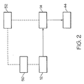
図2は、制御装置10と協働して機能する運転装置の一態様を示したブロック図を含み、ここで矢印付きの実線はレーザビームを表し、また点線は電気制御信号を表す。レーザパワー制御ユニット50は、レーザ発生器12で生成されるレーザビーム13の波長およびパワーが事前に選択された値を含むように、レーザ発生器12の動作を制御する。さらにレーザパワー制御ユニット50は、レーザ発生器12がレーザビーム13を生成する時間間隔を制御することができる。さらに、制御コンピュータ52を提供してレーザパワー制御ユニット50の動作を適切に制御し、それによりレーザパワー制御ユニット50によってレーザ発生器12は、事前に選択された波長およびパワー特性を有するレーザビーム13を事前に選択された時間間隔の間に生成する。同時に制御コンピュータ52は、調整機構16の機能と、またガルバノメータが採用される特定の例ではガルバノメータのモータを制御するように、反射装置14に作動的に関連付けられる。従って制御コンピュータ52は、反射表面によるレーザビーム13の受信と厚さが制御される粘性状態にあるガラス基板の事前選択部分の位置とに関連して、反射表面15の姿勢および位置決めを調節することができる。
FIG. 2 includes a block diagram illustrating one embodiment of an operating device that functions in cooperation with the
一実施形態例によれば、調整機構16は反射装置14の反射表面15を、レーザビーム13の受信と反射装置14の反射表面15でのレーザビームの反射とに関連して複数の様々な姿勢に事前選択期間の間、調節するように構成され得ることが、図1および図2を参照して上で説明した態様、実施形態、および例に基づいて理解されるであろう。結果としてレーザビーム13を、例えば図1に反射レーザビーム17で示されているように、粘性状態にあるガラスリボン44の複数の事前選択部分の方へ、このガラス基板の幅に亘って夫々の事前選択期間の間向けて、それにより事前選択部分の夫々でガラス基板の厚さを制御することができる。より具体的には、図2に示した態様を参照すると、反射レーザビーム17をガラスリボン44の事前選択部分に事前選択期間の間向けるようなやり方で調整機構16が反射表面15の姿勢を制御するように、制御コンピュータ52はプログラムされ得、この事前選択期間は、例えばこれが経験に基づいて決定されたものである場合、または他にガラスリボンの事前選択部分の厚さを様々な程度まで制御する必要がある場合に、変わり得る。
According to an example embodiment, the
例えばガラスリボン44などの基板の製造に関連して現れ得る厚さ不均一性は、種々の背景で生じ得る。例えば、不均一性は基板の単一の局所的部分に存在し得るが、その不均一性は、基板の隣接する複数の部分の厚さに関連して、あるいは基板の単一の局所的部分自体に関連して、存在し得る。いずれにしても、最終的に製造される基板において基板のこの単一の部分の厚さが所望の厚さを得るために、適切なエネルギーレベルおよび波長のレーザビーム13を粘性状態にある基板のその単一の部分に連続的に反射する、反射装置14を提供することが単に必要である。これは、調整機構16に関連する反射表面15の姿勢および位置決めを反射装置14の調整機構16が制御するように、またレーザ発生器12によって生成されるレーザビーム13のエネルギーレベルおよび波長をパワー制御ユニット50が制御するように、コンピュータ52をプログラムすることによって達成される。さらなる例として、厚さ不均一性が存在する2以上の別個の部分が基板に存在することがある。この事例では、反射装置14の調整機構16が、不均一性が存在している基板の2以上の部分に反射ビーム17を連続的に接触させるよう反射表面15の姿勢および位置決めを制御するように、コンピュータ52はプログラムされ得る。さらに、これらの2以上の部分で厚さを変化させることによって最終的に製造される基板において夫々の所望の厚さが得られるように、レーザ発生器12により生成されるレーザビーム13のエネルギーレベルおよび波長をパワー制御ユニット50が制御するよう、コンピュータはプログラムされる。さらに、調整機構16の動作を通じて反射ビーム17を基板の2以上の不均一部分の夫々の位置に必要な期間の間存在させて、これらの各部分の粘度を適切に低下させ、その結果不均一部分の厚さを適切に変化させることができるようコンピュータ52をプログラムしてもよい。また例として、基板に存在する厚さ不均一性は、ガラスリボン44のサイドエッジ48に存在する任意のビードを含め、基板全体に亘って分布し得る。重ねて、レーザ発生器12がパワー制御ユニット50の制御を通じて適切な強度および波長のレーザビーム13を提供するように、また、レーザビーム13が反射装置14の手段を通じて基板を横切って前後に連続的に素早く動かされる際、厚さの修正が施される基板のこれらの部分に、基板製造時に基板のこれらの部分で夫々所望の厚さが得られるレベルまで基板のこれらの部分で粘度を低下させるのに必要な期間の間、レーザビーム13を存在させるように、コンピュータ52は適切にプログラムされ得る。
Thickness non-uniformities that can appear in connection with the manufacture of substrates such as
コンピュータ52を適切にプログラムするのに必要な情報およびデータの開発は、種々の手法で成し遂げることができる。例えば、基板に存在している厚さ不均一性を識別する目的で作り出された厚さの計測追跡を基板で実行してもよい。次いでコンピュータ52を、この計測追跡に基づいて適切にプログラムすることができる。また例として、基板が製造されるときに基板の厚さプロファイルをリアルタイムで監視してもよく、さらに厚さ不均一性を呈している基板の部分が所望の厚さを得るようコンピュータが適切な閉ループ制御アルゴリズムに従って反射装置14およびレーザパワー制御ユニット50を調節することができるように、この監視によって開発された情報をコンピュータ52にフィードバックしてもよい。
The development of information and data necessary to properly program
さらなる態様によれば、ガラスリボン44などのガラス基板は少なくとも2つのガラス層を備えてもよく、これらのガラス層のうちの少なくとも1つが、粘性状態にあるガラス基板の少なくとも1つの事前選択部分を含む。この少なくとも2つのガラス層のうち少なくとも2つ夫々に少なくとも1つの事前選択部分が存在している場合には、採用されるレーザビームの波長は、少なくとも2つのガラス層夫々に存在している粘性状態にあるガラス基板の少なくとも1つの事前選択部分で吸収される夫々のエネルギーの量が、これらの少なくとも2つのガラス層夫々に存在しているガラス基板のこの少なくとも1つの事前選択部分で温度を上昇させかつ粘度を低下させて少なくとも2つのガラス層夫々に存在しているガラスリボンの少なくとも1つの事前選択部分で夫々所望の厚さを十分に得るのに適切なものとなるような波長である。レーザビームがガラス層の夫々で吸収および透過される程度、およびその結果として粘性状態にあるガラス基板の事前選択部分が加熱されてその粘度が低下する程度は、ガラス層の特性だけではなくレーザビームの波長にも依存する。従って、厚さを変化させる2以上のガラス層の全ての事前選択部分にレーザビームを到達させることができるレーザビームの波長が、ガラス層の特性次第で選択され得る。その結果、基板のこれらの事前選択部分を必要に応じて差別的に加熱して、ガラス基板のこれらの事前選択部分の粘度を低下させて事前選択部分の厚さを十分に変化させ、それにより所望の厚さを得る。
According to a further aspect, a glass substrate, such as the
以下に明記する請求項の精神および範囲から逸脱することなく、種々の改変および変形が作製可能であることは当業者には明らかであろう。例えば本書で説明される種々の態様、実施形態、および例は、例えばスロットドロー、アップドロー、およびフロートプロセスなどの他のガラス成形プロセスにより製造されるガラス基板に適用することができる。 It will be apparent to those skilled in the art that various modifications and variations can be made without departing from the spirit and scope of the claims that follow. For example, the various aspects, embodiments, and examples described herein can be applied to glass substrates manufactured by other glass forming processes such as slot draw, up draw, and float processes.
10 制御装置
12 レーザ発生器
13 レーザビーム
14 反射装置
15 反射表面
16 調整機構
17 反射レーザビーム
20 ダウンドローガラス成形装置
44 ガラスリボン
DESCRIPTION OF
Claims (11)
溶融ガラスを供給するステップと、
前記溶融ガラスをリボンに形成するステップであって、前記リボンの端部に張力を印加するステップを備える前記形成するステップと、
前記リボンの厚さを計測するステップと、
前記リボンの少なくとも一部の厚さ不均一性を識別するステップと、
前記識別した厚さ不均一性に対応する粘性状態の前記リボンの少なくとも一部を事前選択するステップであって、該粘性状態の前記リボンの前記少なくとも1つの事前選択部分の厚さが固定されていないステップと、
前記粘性状態の前記リボンの前記少なくとも一つの事前選択部分を、前記事前選択部分に当たるように向けたレーザビームで加熱するステップと、を備え、
前記加熱するステップは、前記リボンの前記少なくとも一つの事前選択部分に所定の厚さを得させしめ、前記加熱するステップは、前記計測された厚さに応じて、前記事前選択部分に当てる前記レーザビームのパワーと滞留時間と波長の少なくとも1つを制御するステップを備える、ことを特徴とする方法。 A method for controlling the thickness between the first main surface and a second major surface of at least one preselected portion of the glass board,
The steps of: providing a molten glass,
The molten glass and forming the ribbon, and wherein the step of forming comprises the step of applying tension to the ends of the ribbon,
Measuring the thickness of the ribbon;
Identifying a thickness non-uniformity of at least a portion of the ribbon;
Pre-selecting at least a portion of the viscous ribbon corresponding to the identified thickness non-uniformity , wherein the thickness of the at least one pre-selected portion of the viscous ribbon is fixed. No steps and
Heating the at least one preselected portion of the viscous ribbon with a laser beam directed to impinge on the preselected portion;
Wherein the step of said heating is accounted let obtain a predetermined thickness on said at least one preselected portion of said ribbon, said step of heating, in accordance with the thickness of the measured, exposure to the preselected portion Controlling at least one of laser beam power, dwell time, and wavelength.
前記少なくとも1つの事前選択部分は前記リボンの延伸方向において前記成形ウェッジの底部に隣接して位置することを特徴とする請求項1から6のいずれか1項記載の方法。 The forming step comprises stretching the ribbon from the bottom of a forming wedge;
7. A method according to any one of the preceding claims, wherein the at least one preselected portion is located adjacent to the bottom of the forming wedge in the direction of drawing of the ribbon .
ある量のガラスから前記ガラスリボンを延伸するステップであって、該ガラスリボンが少なくとも2つのガラス層を備えるステップと、
前記ガラスリボンの厚さ不均一性を識別するステップと、
前記識別した厚さ不均一性に対応する粘性状態の前記ガラスリボンの少なくとも一部を事前選択するステップであって、前記粘性状態の前記ガラスリボンの前記少なくとも1つの事前選択部分は前記少なくとも2つのガラス層のうちの少なくとも2つ夫々に存在するステップと、
レーザビームを生成するステップと、
前記レーザビームを前記粘性状態の前記ガラスリボンの前記少なくとも1つの事前選択部分に向けるステップであって、前記粘性状態の前記ガラスリボンの前記少なくとも1つの事前選択部分の厚さが固定されておらず、前記レーザビームの波長は、前記少なくとも2つのガラス層の前記少なくとも2つ夫々に存在している前記粘性状態の前記ガラスリボンの前記少なくとも1つの事前選択部分で吸収される夫々のエネルギーの量が、前記少なくとも2つのガラス層の前記少なくとも2つ夫々に存在している前記粘性状態の前記ガラスリボンの前記少なくとも1つの事前選択部分で温度を上昇させかつ粘度を低下させて前記少なくとも2つのガラス層の前記少なくとも2つ夫々に存在している前記粘性状態の前記ガラスリボンの前記少なくとも1つの事前選択部分で夫々所望の厚さを十分に得るのに適切なものとなるような、波長であるステップとを備えることを特徴とする方法。 In a method of controlling the thickness of at least one preselected portion of a glass ribbon,
Stretching the glass ribbon from an amount of glass, the glass ribbon comprising at least two glass layers;
Identifying the thickness non-uniformity of the glass ribbon;
Comprising the steps of pre-selecting at least a portion of the glass ribbon viscosity state corresponding to the thickness non-uniformity was the identification, the at least one preselected portion of said glass ribbon of the viscous state at least two A step present in at least two of the glass layers ;
Generating a laser beam;
Comprising the steps of directing said laser beam to said at least one preselected portion of said glass ribbon of the viscous state, the thickness of said at least one preselected portion of said glass ribbon viscous state is not fixed , the wavelength of the laser beam, the amount of the at least one respective energy absorbed by the preselected portion of said glass ribbon of the viscous state is present people in at least two of said at least two each of the glass layer , wherein at least one of the at least two glass layers reduce the and viscosity the temperature is increased at preselected portions of the glass ribbon of said at least two said viscous state that exists people in at least two each of the glass layer the less the of the at least two said glass ribbon of the viscous state respectively is present Such that the appropriate to achieve sufficiently respective desired thickness in one preselected portion, the method characterized by comprising the steps the wavelength.
Applications Claiming Priority (3)
| Application Number | Priority Date | Filing Date | Title |
|---|---|---|---|
| US13/669,994 US8904822B2 (en) | 2012-11-06 | 2012-11-06 | Thickness control of substrates |
| US13/669,994 | 2012-11-06 | ||
| PCT/US2013/067714 WO2014074384A1 (en) | 2012-11-06 | 2013-10-31 | Thickness control of substrates |
Publications (3)
| Publication Number | Publication Date |
|---|---|
| JP2015536895A JP2015536895A (en) | 2015-12-24 |
| JP2015536895A5 JP2015536895A5 (en) | 2016-12-15 |
| JP6158342B2 true JP6158342B2 (en) | 2017-07-05 |
Family
ID=50621108
Family Applications (1)
| Application Number | Title | Priority Date | Filing Date |
|---|---|---|---|
| JP2015540781A Active JP6158342B2 (en) | 2012-11-06 | 2013-10-31 | Substrate thickness control |
Country Status (6)
| Country | Link |
|---|---|
| US (1) | US8904822B2 (en) |
| JP (1) | JP6158342B2 (en) |
| KR (2) | KR102013426B1 (en) |
| CN (1) | CN104768883B (en) |
| TW (1) | TWI588305B (en) |
| WO (1) | WO2014074384A1 (en) |
Families Citing this family (18)
| Publication number | Priority date | Publication date | Assignee | Title |
|---|---|---|---|---|
| US9290403B2 (en) | 2013-02-25 | 2016-03-22 | Corning Incorporated | Repositionable heater assemblies for glass production lines and methods of managing temperature of glass in production lines |
| US9556051B2 (en) | 2014-09-22 | 2017-01-31 | Corning Incorporated | Methods for controlling the thickness wedge in a glass ribbon |
| DE102014119064A1 (en) | 2014-12-18 | 2016-06-23 | Schott Ag | Glass film with specially formed edge, process for its production and its use |
| JP6498933B2 (en) * | 2014-12-29 | 2019-04-10 | AvanStrate株式会社 | Manufacturing method and manufacturing apparatus for glass substrate for display |
| WO2017053843A1 (en) * | 2015-09-24 | 2017-03-30 | Corning Incorporated | Methods and apparatus for manufacturing glass |
| JP2017119617A (en) * | 2015-12-28 | 2017-07-06 | AvanStrate株式会社 | Glass substrate manufacturing method, and glass substrate manufacturing apparatus |
| DE102017101808A1 (en) | 2016-02-04 | 2017-08-10 | Schott Ag | Method for thickness control of a substrate |
| DE102018111543A1 (en) | 2017-05-22 | 2018-11-22 | Schott Ag | Method and device for thickness control of a material band |
| TW201912597A (en) * | 2017-08-24 | 2019-04-01 | 美商康寧公司 | Methods and apparatus for selectively altering fictive temperature of glass-based articles |
| JP7264908B2 (en) * | 2018-03-06 | 2023-04-25 | コーニング インコーポレイテッド | Apparatus and method for controlling substrate thickness |
| WO2020005555A1 (en) | 2018-06-28 | 2020-01-02 | Corning Incorporated | Continuous methods of making glass ribbon and as-drawn glass articles from the same |
| KR20210109051A (en) | 2019-01-25 | 2021-09-03 | 코닝 인코포레이티드 | Dual-Elevation Edge Roll System for Fusion Downdraw Glass Forming |
| WO2020210095A1 (en) * | 2019-04-12 | 2020-10-15 | Corning Incorporated | Methods and apparatus for manufacturing a ribbon |
| JP2022548842A (en) * | 2019-09-13 | 2022-11-22 | コーニング インコーポレイテッド | Systems and methods for forming glass ribbons using heating devices |
| US20240051862A1 (en) * | 2019-10-22 | 2024-02-15 | Corning Incorporated | Energy delivery optimization for laser thickness control of fusion glass system and methods |
| US20220396517A1 (en) * | 2019-12-02 | 2022-12-15 | Corning Incorporated | Methods and apparatus for manufacturing a glass ribbon |
| CN112279499B (en) * | 2020-10-22 | 2022-06-07 | 科立视材料科技有限公司 | Method and apparatus for controlling glass ribbon stress |
| WO2023096759A1 (en) * | 2021-11-23 | 2023-06-01 | Corning Incorporated | Systems and methods for glass streak improvement via high resolution heating |
Family Cites Families (39)
| Publication number | Priority date | Publication date | Assignee | Title |
|---|---|---|---|---|
| US3694181A (en) * | 1971-06-01 | 1972-09-26 | Ppg Industries Inc | Apparatus for controlling glass fractures |
| JP3589486B2 (en) * | 1994-06-29 | 2004-11-17 | 株式会社町田製作所 | Microlens manufacturing method |
| US5768022A (en) * | 1995-03-08 | 1998-06-16 | Brown University Research Foundation | Laser diode having in-situ fabricated lens element |
| US5604635A (en) * | 1995-03-08 | 1997-02-18 | Brown University Research Foundation | Microlenses and other optical elements fabricated by laser heating of semiconductor doped and other absorbing glasses |
| US5742026A (en) * | 1995-06-26 | 1998-04-21 | Corning Incorporated | Processes for polishing glass and glass-ceramic surfaces using excimer laser radiation |
| JPH1097715A (en) * | 1996-07-31 | 1998-04-14 | Asahi Komagu Kk | Substrate for magnetic recording medium and magnetic recording medium |
| EP0959051A4 (en) | 1996-08-13 | 1999-12-15 | Nippon Sheet Glass Co Ltd | Laser machining method for glass substrate, diffraction type optical device fabricated by the machining method, and method of manufacturing optical device |
| DE19918936A1 (en) * | 1999-04-27 | 2000-11-02 | Schott Glas | Method and device for producing single glass panes |
| DE10128636C1 (en) * | 2001-06-13 | 2002-08-01 | Schott Glas | Process for selectively influencing the glass thickness in the manufacture of flat glass and device for carrying out the process |
| JP2003307602A (en) * | 2002-04-18 | 2003-10-31 | Nippon Sheet Glass Co Ltd | Planar lens and method for manufacturing planar lens array |
| US20050160767A1 (en) * | 2004-01-28 | 2005-07-28 | Robert Novak | Horizontal sheet movement control in drawn glass fabrication |
| KR100910952B1 (en) * | 2005-04-15 | 2009-08-05 | 아사히 가라스 가부시키가이샤 | Method for reducing diameter of bubble existing inside of glass plate |
| US20070140311A1 (en) * | 2005-12-20 | 2007-06-21 | House Keith L | Method and apparatus for characterizing a glass ribbon |
| CN101437764B (en) * | 2006-05-11 | 2012-03-21 | 旭硝子株式会社 | Method and apparatus for removing bubbles from molten glass and process for producing glass |
| US7570366B2 (en) * | 2007-02-21 | 2009-08-04 | Corning Incorporated | Apparatus for measuring defects in a glass sheet |
| TWI370894B (en) * | 2007-02-26 | 2012-08-21 | Corning Inc | Method for measuring distortion |
| EP2168001B1 (en) * | 2007-07-16 | 2013-03-06 | Corning Incorporated | Microalignment using laser-softened glass bumps |
| JP5327702B2 (en) | 2008-01-21 | 2013-10-30 | 日本電気硝子株式会社 | Manufacturing method of glass substrate |
| US20090217705A1 (en) * | 2008-02-29 | 2009-09-03 | Filippov Andrey V | Temperature control of glass fusion by electromagnetic radiation |
| WO2009151513A1 (en) * | 2008-05-01 | 2009-12-17 | Corning Incorporated | Raised features on transparent substrates and related methods |
| US7920257B2 (en) * | 2008-08-27 | 2011-04-05 | Corning Incorporated | Systems and methods for determining the shape of glass sheets |
| US8899078B2 (en) * | 2008-11-26 | 2014-12-02 | Corning Incorporated | Glass sheet stabilizing system, glass manufacturing system and method for making a glass sheet |
| DE102009008292B4 (en) * | 2009-02-10 | 2014-09-25 | Schott Ag | Capacitor and method for producing such |
| CN102414134B (en) * | 2009-02-27 | 2015-01-21 | 康宁股份有限公司 | Method for shaping regions on a glass ribbon |
| US8037716B2 (en) | 2009-02-27 | 2011-10-18 | Corning Incorporated | Thermal control of the bead portion of a glass ribbon |
| US8590873B2 (en) * | 2009-04-08 | 2013-11-26 | Corning Incorporated | Method and device for restraining movement of continuously traveling glass sheet |
| ATE551304T1 (en) * | 2009-05-13 | 2012-04-15 | Corning Inc | METHOD AND EQUIPMENT FOR SHAPING ENDLESS GLASS PANELS |
| TWI395630B (en) | 2009-06-30 | 2013-05-11 | Mitsuboshi Diamond Ind Co Ltd | Apparatus for processing glass substrate by laser beam |
| JP5698753B2 (en) * | 2009-10-14 | 2015-04-08 | コーニング インコーポレイテッド | Sheet thickness control method and apparatus |
| US20110100058A1 (en) * | 2009-10-30 | 2011-05-05 | Dickinson Jr James Edward | Formation of glass bumps with increased height using thermal annealing |
| WO2011066064A2 (en) | 2009-11-24 | 2011-06-03 | Corning Incorporated | Method and apparatus for making a glass sheet with controlled thickness |
| KR101736262B1 (en) * | 2010-02-18 | 2017-05-16 | 니폰 덴키 가라스 가부시키가이샤 | Manufacturing method for glass film and manufacturing device therefor |
| US9656901B2 (en) * | 2010-03-03 | 2017-05-23 | Nippon Electric Glass Co., Ltd. | Method of manufacturing a glass roll |
| JP5720885B2 (en) * | 2010-03-03 | 2015-05-20 | 日本電気硝子株式会社 | Glass roll and method for producing glass roll |
| KR101850164B1 (en) * | 2010-05-26 | 2018-04-18 | 코닝 인코포레이티드 | Apparatus and method for controlling thickness of a flowing ribbon of molten glass |
| US8397536B2 (en) | 2010-05-26 | 2013-03-19 | Corning Incorporated | Apparatus and method for controlling thickness of a flowing ribbon of molten glass |
| US9676649B2 (en) * | 2011-08-26 | 2017-06-13 | Corning Incorporated | Glass substrates with strategically imprinted B-side features and methods for manufacturing the same |
| US8459062B2 (en) * | 2011-09-27 | 2013-06-11 | Corning Incorporated | Apparatus and methods for producing a glass ribbon |
| US8677783B2 (en) * | 2011-11-28 | 2014-03-25 | Corning Incorporated | Method for low energy separation of a glass ribbon |
-
2012
- 2012-11-06 US US13/669,994 patent/US8904822B2/en not_active Expired - Fee Related
-
2013
- 2013-10-31 KR KR1020157014445A patent/KR102013426B1/en active IP Right Grant
- 2013-10-31 KR KR1020197023987A patent/KR102176561B1/en active IP Right Grant
- 2013-10-31 JP JP2015540781A patent/JP6158342B2/en active Active
- 2013-10-31 CN CN201380058100.3A patent/CN104768883B/en active Active
- 2013-10-31 WO PCT/US2013/067714 patent/WO2014074384A1/en active Application Filing
- 2013-11-06 TW TW102140357A patent/TWI588305B/en active
Also Published As
| Publication number | Publication date |
|---|---|
| CN104768883B (en) | 2018-01-16 |
| KR102176561B1 (en) | 2020-11-10 |
| US8904822B2 (en) | 2014-12-09 |
| TW201420822A (en) | 2014-06-01 |
| TWI588305B (en) | 2017-06-21 |
| KR102013426B1 (en) | 2019-08-22 |
| KR20190099098A (en) | 2019-08-23 |
| CN104768883A (en) | 2015-07-08 |
| JP2015536895A (en) | 2015-12-24 |
| KR20150083098A (en) | 2015-07-16 |
| US20140123703A1 (en) | 2014-05-08 |
| WO2014074384A1 (en) | 2014-05-15 |
Similar Documents
| Publication | Publication Date | Title |
|---|---|---|
| JP6158342B2 (en) | Substrate thickness control | |
| US8383983B2 (en) | Substrate cutting apparatus and method of cutting substrate using the same | |
| JP5698753B2 (en) | Sheet thickness control method and apparatus | |
| TWI331685B (en) | Method and apparatus for correcting a defective pixel of a liquid crystal display | |
| CN108136543A (en) | The laser pre-treated method of the base material by coating that will be cut by laser | |
| US10017411B2 (en) | Methods of separating a glass web | |
| US20200299173A1 (en) | Fusion draw apparatus and methods of making a glass ribbon | |
| WO2012099286A1 (en) | Apparatus and method for processing light guide plate using laser | |
| US20210053858A1 (en) | Apparatus and method for controlling substrate thickness | |
| US20240051862A1 (en) | Energy delivery optimization for laser thickness control of fusion glass system and methods | |
| TW202334044A (en) | Systems and methods for glass streak improvement via high resolution heating | |
| KR20220043151A (en) | Laser Debit Removal Systems and Methods | |
| US20220212976A1 (en) | Methods and apparatus for manufacturing a ribbon | |
| JP2024507336A (en) | System and method for adjustable edge cooling means for slot drawdown glass |
Legal Events
| Date | Code | Title | Description |
|---|---|---|---|
| A521 | Request for written amendment filed |
Free format text: JAPANESE INTERMEDIATE CODE: A523 Effective date: 20161024 |
|
| A621 | Written request for application examination |
Free format text: JAPANESE INTERMEDIATE CODE: A621 Effective date: 20161024 |
|
| A871 | Explanation of circumstances concerning accelerated examination |
Free format text: JAPANESE INTERMEDIATE CODE: A871 Effective date: 20161024 |
|
| A975 | Report on accelerated examination |
Free format text: JAPANESE INTERMEDIATE CODE: A971005 Effective date: 20161117 |
|
| A131 | Notification of reasons for refusal |
Free format text: JAPANESE INTERMEDIATE CODE: A131 Effective date: 20161206 |
|
| A521 | Request for written amendment filed |
Free format text: JAPANESE INTERMEDIATE CODE: A523 Effective date: 20170228 |
|
| TRDD | Decision of grant or rejection written | ||
| A01 | Written decision to grant a patent or to grant a registration (utility model) |
Free format text: JAPANESE INTERMEDIATE CODE: A01 Effective date: 20170509 |
|
| A61 | First payment of annual fees (during grant procedure) |
Free format text: JAPANESE INTERMEDIATE CODE: A61 Effective date: 20170607 |
|
| R150 | Certificate of patent or registration of utility model |
Ref document number: 6158342 Country of ref document: JP Free format text: JAPANESE INTERMEDIATE CODE: R150 |
|
| R250 | Receipt of annual fees |
Free format text: JAPANESE INTERMEDIATE CODE: R250 |
|
| R250 | Receipt of annual fees |
Free format text: JAPANESE INTERMEDIATE CODE: R250 |
|
| R250 | Receipt of annual fees |
Free format text: JAPANESE INTERMEDIATE CODE: R250 |
|
| R250 | Receipt of annual fees |
Free format text: JAPANESE INTERMEDIATE CODE: R250 |