JP6157840B2 - Nondestructive inspection device with ergonomic grip and related methods - Google Patents
Nondestructive inspection device with ergonomic grip and related methods Download PDFInfo
- Publication number
- JP6157840B2 JP6157840B2 JP2012252496A JP2012252496A JP6157840B2 JP 6157840 B2 JP6157840 B2 JP 6157840B2 JP 2012252496 A JP2012252496 A JP 2012252496A JP 2012252496 A JP2012252496 A JP 2012252496A JP 6157840 B2 JP6157840 B2 JP 6157840B2
- Authority
- JP
- Japan
- Prior art keywords
- grip
- workpiece
- operator
- ultrasonic sensor
- inspection device
- Prior art date
- Legal status (The legal status is an assumption and is not a legal conclusion. Google has not performed a legal analysis and makes no representation as to the accuracy of the status listed.)
- Expired - Fee Related
Links
- 238000007689 inspection Methods 0.000 title claims description 160
- 238000000034 method Methods 0.000 title claims description 30
- 230000001066 destructive effect Effects 0.000 claims description 84
- 238000004891 communication Methods 0.000 claims description 24
- 239000003550 marker Substances 0.000 claims description 15
- 230000004044 response Effects 0.000 claims description 14
- 239000000499 gel Substances 0.000 description 7
- 230000008878 coupling Effects 0.000 description 4
- 238000010168 coupling process Methods 0.000 description 4
- 238000005859 coupling reaction Methods 0.000 description 4
- 230000005540 biological transmission Effects 0.000 description 3
- 238000010586 diagram Methods 0.000 description 3
- 238000012545 processing Methods 0.000 description 3
- 230000005856 abnormality Effects 0.000 description 2
- 230000008901 benefit Effects 0.000 description 2
- 238000012986 modification Methods 0.000 description 2
- 230000004048 modification Effects 0.000 description 2
- 238000009659 non-destructive testing Methods 0.000 description 2
- 230000004913 activation Effects 0.000 description 1
- 239000011324 bead Substances 0.000 description 1
- 239000002131 composite material Substances 0.000 description 1
- 238000010276 construction Methods 0.000 description 1
- 239000006260 foam Substances 0.000 description 1
- 238000005286 illumination Methods 0.000 description 1
- 230000003993 interaction Effects 0.000 description 1
- 230000001678 irradiating effect Effects 0.000 description 1
- 230000007246 mechanism Effects 0.000 description 1
- 230000008569 process Effects 0.000 description 1
- 230000003252 repetitive effect Effects 0.000 description 1
- 230000035939 shock Effects 0.000 description 1
- 239000007779 soft material Substances 0.000 description 1
- 238000001179 sorption measurement Methods 0.000 description 1
- 238000002604 ultrasonography Methods 0.000 description 1
- XLYOFNOQVPJJNP-UHFFFAOYSA-N water Substances O XLYOFNOQVPJJNP-UHFFFAOYSA-N 0.000 description 1
Images


Classifications
-
- G—PHYSICS
- G01—MEASURING; TESTING
- G01N—INVESTIGATING OR ANALYSING MATERIALS BY DETERMINING THEIR CHEMICAL OR PHYSICAL PROPERTIES
- G01N29/00—Investigating or analysing materials by the use of ultrasonic, sonic or infrasonic waves; Visualisation of the interior of objects by transmitting ultrasonic or sonic waves through the object
- G01N29/22—Details, e.g. general constructional or apparatus details
- G01N29/225—Supports, positioning or alignment in moving situation
- G01N29/226—Handheld or portable devices
-
- G—PHYSICS
- G01—MEASURING; TESTING
- G01N—INVESTIGATING OR ANALYSING MATERIALS BY DETERMINING THEIR CHEMICAL OR PHYSICAL PROPERTIES
- G01N29/00—Investigating or analysing materials by the use of ultrasonic, sonic or infrasonic waves; Visualisation of the interior of objects by transmitting ultrasonic or sonic waves through the object
- G01N29/04—Analysing solids
-
- G—PHYSICS
- G01—MEASURING; TESTING
- G01N—INVESTIGATING OR ANALYSING MATERIALS BY DETERMINING THEIR CHEMICAL OR PHYSICAL PROPERTIES
- G01N29/00—Investigating or analysing materials by the use of ultrasonic, sonic or infrasonic waves; Visualisation of the interior of objects by transmitting ultrasonic or sonic waves through the object
- G01N29/22—Details, e.g. general constructional or apparatus details
- G01N29/26—Arrangements for orientation or scanning by relative movement of the head and the sensor
- G01N29/265—Arrangements for orientation or scanning by relative movement of the head and the sensor by moving the sensor relative to a stationary material
-
- A—HUMAN NECESSITIES
- A61—MEDICAL OR VETERINARY SCIENCE; HYGIENE
- A61B—DIAGNOSIS; SURGERY; IDENTIFICATION
- A61B8/00—Diagnosis using ultrasonic, sonic or infrasonic waves
- A61B8/42—Details of probe positioning or probe attachment to the patient
- A61B8/4272—Details of probe positioning or probe attachment to the patient involving the acoustic interface between the transducer and the tissue
- A61B8/4281—Details of probe positioning or probe attachment to the patient involving the acoustic interface between the transducer and the tissue characterised by sound-transmitting media or devices for coupling the transducer to the tissue
-
- A—HUMAN NECESSITIES
- A61—MEDICAL OR VETERINARY SCIENCE; HYGIENE
- A61B—DIAGNOSIS; SURGERY; IDENTIFICATION
- A61B8/00—Diagnosis using ultrasonic, sonic or infrasonic waves
- A61B8/44—Constructional features of the ultrasonic, sonic or infrasonic diagnostic device
- A61B8/4444—Constructional features of the ultrasonic, sonic or infrasonic diagnostic device related to the probe
- A61B8/4455—Features of the external shape of the probe, e.g. ergonomic aspects
-
- G—PHYSICS
- G01—MEASURING; TESTING
- G01N—INVESTIGATING OR ANALYSING MATERIALS BY DETERMINING THEIR CHEMICAL OR PHYSICAL PROPERTIES
- G01N2291/00—Indexing codes associated with group G01N29/00
- G01N2291/04—Wave modes and trajectories
- G01N2291/044—Internal reflections (echoes), e.g. on walls or defects
Description
本発明の例示的な一実施形態は、概して非破壊検査装置とそれに関連する方法に関し、具体的には人間工学的グリップを有する非破壊検査装置とそれに関連する方法に関する。 One exemplary embodiment of the present invention relates generally to non-destructive inspection devices and related methods, and in particular to non-destructive inspection devices having ergonomic grips and related methods.
様々なワークピースに対し、その様々な特徴を決定するために非破壊検査が行われる。例えば、翼、胴体セクションなどの様々な構造用パネルは非破壊検査を受ける。非破壊検査装置は、通常、ワークビース中へと信号を発信し、発信した信号に応答する帰還信号を受信するセンサを含む。非破壊検査装置のセンサは、例えば、超音波信号の発信及び受信を行う超音波センサである。 Non-destructive testing is performed on various workpieces to determine their various characteristics. For example, various structural panels such as wings and fuselage sections undergo non-destructive inspection. Non-destructive inspection devices typically include a sensor that transmits a signal into the work bead and receives a feedback signal in response to the transmitted signal. The sensor of the nondestructive inspection apparatus is, for example, an ultrasonic sensor that transmits and receives an ultrasonic signal.
使用時には、センサはワークピースの上に配置される。次いで、センサが作動されると、センサはワークピース中に信号を発信し、センサが発信した信号に応答する帰還信号を受信する。帰還信号を解析することにより、例えばワークピースの厚みのようなワークピースの様々な特徴、及び/又はワークピースの調べられている部分内に存在しうる異常が決定される。ワークピース上でセンサを移動させて、ワークピースの複数の部分の各々を調べることにより、非破壊検査装置はワークピースの殆ど全域を効率的に検査することができる。 In use, the sensor is placed on the workpiece. Then, when the sensor is activated, the sensor emits a signal in the workpiece and receives a feedback signal in response to the signal emitted by the sensor. By analyzing the feedback signal, various features of the workpiece, such as, for example, the thickness of the workpiece, and / or anomalies that may exist within the part being examined are determined. By moving the sensor over the workpiece and examining each of the plurality of portions of the workpiece, the non-destructive inspection device can efficiently inspect almost the entire area of the workpiece.
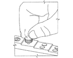
幾つかの非破壊検査装置は、ワークピースの上に手動で配置された後、ワークピースの殆ど全域を調べるために、ワークピース上で手動により再配置されるセンサを含む。すなわち、オペレータは、通常、センサを把持し、ワークピース上の任意の数の位置にセンサを繰り返し再配置しなければならない。また、センサとワークピースとを効率的に連結させるため、具体的には、センサによって発信された信号と、ワークピースから受信される帰還信号とを効率的に連結させるために、オペレータは、ワークピースの表面に対してセンサを押し付けようとして力を入れる。その結果、センサの配置と移動は、一般に、オペレータの力を必要とする。オペレータが払うべき努力は、一般に、センサが小型である程大い。例えば、図1に示すように、超音波センサ10は、一般に非常に小さく、例えばオペレータの指より小さい。このために、オペレータは、センサの把持を多少困難に感じる場合があり、具体的には、センサを把持するだけでなく、センサをその下に位置するワークピースと接触させるために必要な力を加えることが難しいと感じる。
Some non-destructive inspection devices include sensors that are manually placed on the workpiece and then manually repositioned on the workpiece to examine almost the entire area of the workpiece. That is, the operator typically has to grip the sensor and repeatedly reposition the sensor at any number of positions on the workpiece. In order to efficiently connect the sensor and the workpiece, specifically, in order to efficiently connect the signal transmitted by the sensor and the feedback signal received from the workpiece, the operator A force is applied to press the sensor against the surface of the piece. As a result, sensor placement and movement generally requires operator power. The effort that an operator should make is generally greater as the sensor is smaller. For example, as shown in FIG. 1, the
センサの把持と、必要な力をワークピースに印加することとに関してオペレータが直面する困難性は、時として、オペレータがワークピース上にセンサを配置してその上で移動させるときに生じる反復運動により増大する。加えて、ワークピースが比較的大きい場合があり、オペレータはセンサを適切に配置してワークピースの少なくとも一の部分を調べるために、ワークピースの対応する部分に到達する必要があるので、検査デバイスを操作する間に、オペレータはやや不愉快な一時停止を余儀なくされる。 The difficulty faced by the operator with respect to gripping the sensor and applying the necessary force to the workpiece is sometimes due to the repetitive movement that occurs when the operator places the sensor on the workpiece and moves it over it. Increase. In addition, since the workpiece may be relatively large and the operator needs to reach the corresponding part of the workpiece in order to properly position the sensor and examine at least one part of the workpiece, the inspection device The operator is forced to pause somewhat unpleasantly during the operation.
ワークピースの非破壊検査を容易にするために、例示的ない一実施形態により非破壊検査装置、システム、及び関連方法が提供される。これに関して、一実施形態の非破壊検査システムとそれに関連する方法は、例えば、比較的小さいセンサを把持する必要、及びセンサとその下のワークピースとの動作可能な接触を確実にするためにセンサに力を加える必要を低減又は排除することにより、オペレータが、もっと人間工学的に非破壊検査装置と相互作用することを可能にする。このように、非破壊検査装置とそれに関連する方法は、オペレータが、ワークピースの上にセンサを繰り返し配置すること、及び以前より小さい力で、ワークピース上でセンサを移動させることを可能にする。 To facilitate non-destructive inspection of a workpiece, a non-destructive inspection apparatus, system, and related methods are provided according to one non-exemplary embodiment. In this regard, the non-destructive inspection system and associated method of one embodiment provides, for example, a sensor to ensure that a relatively small sensor needs to be gripped and an operable contact between the sensor and the workpiece under it. By reducing or eliminating the need to apply force to the operator, the operator can interact more ergonomically with non-destructive inspection equipment. In this way, the non-destructive inspection apparatus and associated methods allow an operator to repeatedly place the sensor on the workpiece and move the sensor on the workpiece with less force than before. .
本発明の一態様によれば、ワークピースと動作可能に接触するように配置される超音波センサを含む非破壊検査装置が提供される。超音波センサは、ワークピース中へと超音波信号を発信し、そのようにして発信された超音波信号に応答する帰還信号を受信する。非破壊検査装置は、超音波センサに動作可能に結合して、超音波センサと同時に移動可能なグリップも含む。グリップは、オペレータによって超音波検査装置に印加される力がグリップを介して超音波センサに伝わるように、オペレータの手のひら(例えば、オペレータの手のひらの大部分)を支持する。 According to one aspect of the present invention, a non-destructive inspection apparatus is provided that includes an ultrasonic sensor disposed in operative contact with a workpiece. The ultrasonic sensor transmits an ultrasonic signal into the workpiece and receives a feedback signal in response to the ultrasonic signal thus transmitted. The non-destructive inspection apparatus also includes a grip operably coupled to the ultrasonic sensor and movable simultaneously with the ultrasonic sensor. The grip supports the operator's palm (eg, the majority of the operator's palm) so that the force applied by the operator to the ultrasonic inspection device is transmitted through the grip to the ultrasonic sensor.
有利には、非破壊検査装置は、それぞれ異なる複数のオペレータの手のひらに適合する複数のグリップを含む。これに関して、複数のグリップは、超音波センサに交換可能に結合させることができる。有利には、グリップは、オペレータの手のひらに適合するゲルパッドを含む。有利には、非破壊検査装置は、超音波センサとワークピースとの連結を助けるばね荷重源も含む。有利には、装置のグリップは、オペレータが作動させる少なくとも一つの入力要素を含む。有利には、非破壊検査装置は、超音波センサとグリップとに動作可能に結合されて、ワークピースに対して超音波センサを一時的に取り付けるように構成された吸着デバイスも含む。 Advantageously, the non-destructive inspection device includes a plurality of grips that fit in the palms of different operators. In this regard, the plurality of grips can be interchangeably coupled to the ultrasonic sensor. Advantageously, the grip includes a gel pad that fits in the palm of the operator. Advantageously, the non-destructive inspection apparatus also includes a spring load source that assists in coupling the ultrasonic sensor and the workpiece. Advantageously, the grip of the device includes at least one input element that is actuated by an operator. Advantageously, the non-destructive inspection apparatus also includes a suction device operably coupled to the ultrasonic sensor and the grip and configured to temporarily attach the ultrasonic sensor to the workpiece.
有利には、非破壊検査装置は、検査位置を特定する位置決めシステムと通信する通信インターフェースを含む。好適には、一実施形態の通信インターフェースは、非破壊検査装置の位置を規定する位置決め信号を受信することができる。好適には、通信インターフェースは、検査位置を示すマーカを受信することができる。 Advantageously, the non-destructive inspection device includes a communication interface in communication with a positioning system that identifies the inspection location. Preferably, the communication interface of an embodiment can receive a positioning signal that defines the position of the non-destructive inspection device. Preferably, the communication interface can receive a marker indicating the examination position.
本発明の更なる態様によれば、非破壊検査装置と、非破壊検査装置と通信するコンピュータとを含む非破壊検査システムが提供される。この非破壊検査装置は、ワークピースと動作可能に接触するように配置される超音波センサを含む。超音波センサは、ワークピース中へと超音波信号を発信し、そのようにして発信された超音波信号に応答する帰還信号を受信する。非破壊検査装置は、超音波センサに動作可能に結合して超音波センサと協働するグリップも含む。グリップは、オペレータの手のひら(例えば、オペレータの手のひら)を支持するように構成される。加えて、グリップは、オペレータが作動させる少なくとも一つの入力要素を含む。コンピュータは、超音波センサによって受信された帰還信号に関する情報を受取るように構成される。 According to a further aspect of the present invention, a nondestructive inspection system is provided that includes a nondestructive inspection device and a computer in communication with the nondestructive inspection device. The non-destructive inspection apparatus includes an ultrasonic sensor that is disposed in operative contact with a workpiece. The ultrasonic sensor transmits an ultrasonic signal into the workpiece and receives a feedback signal in response to the ultrasonic signal thus transmitted. The nondestructive inspection apparatus also includes a grip that is operably coupled to the ultrasonic sensor and cooperates with the ultrasonic sensor. The grip is configured to support an operator's palm (eg, the operator's palm). In addition, the grip includes at least one input element that is activated by an operator. The computer is configured to receive information regarding the feedback signal received by the ultrasonic sensor.
有利には、非破壊検査装置は、オペレータが作動させる複数の入力要素を含む。有利には、非破壊検査装置は、異なる複数のオペレータそれぞれの手のひらに適合する複数のグリップをさらに含む。有利には、複数のグリップは、超音波センサに交換可能に結合される。有利には、非破壊検査装置のグリップは、オペレータの手のひらに適合するゲルパッドを含む。有利には、非破壊検査装置は、超音波センサとワークピースとの連結を助けるばね荷重源も含む。有利には、非破壊検査装置は、超音波センサとグリップとに動作可能に結合されて、ワークピースに対して超音波センサを一時的に取り付けるように構成された吸着デバイスも含む。 Advantageously, the non-destructive inspection device includes a plurality of input elements that are activated by an operator. Advantageously, the non-destructive inspection device further comprises a plurality of grips adapted to the palms of different operators. Advantageously, the plurality of grips are interchangeably coupled to the ultrasonic sensor. Advantageously, the grip of the non-destructive inspection device includes a gel pad that fits the palm of the operator. Advantageously, the non-destructive inspection apparatus also includes a spring load source that assists in coupling the ultrasonic sensor and the workpiece. Advantageously, the non-destructive inspection apparatus also includes a suction device operably coupled to the ultrasonic sensor and the grip and configured to temporarily attach the ultrasonic sensor to the workpiece.
有利には、非破壊検査装置は、検査位置を特定する位置決めシステムと通信する通信インターフェースを含む。好適には、通信インターフェースは、非破壊検査装置の位置を規定する位置決め信号を受信することができる。好適には、通信インターフェースは、検査位置を示すマーカを受信することができる。 Advantageously, the non-destructive inspection device includes a communication interface in communication with a positioning system that identifies the inspection location. Preferably, the communication interface is capable of receiving a positioning signal that defines the position of the non-destructive inspection device. Preferably, the communication interface may receive the marker indicating the inspection position.
本発明のさらなる態様によれば、ワークピースの非破壊検査方法が提供され、この方法は、超音波センサをワークピースに動作可能に接触させることと、超音波センサに動作可能に結合されるグリップによりオペレータの手のひらを支持することとを含む。この方法は、また、超音波センサからワークピース中へと超音波信号を発信することと、そのようにして発信された超音波信号に応答する帰還信号を受信することとを含む。この方法は、また、オペレータによってグリップに印加されて、グリップから超音波センサに伝達される力に応答して、グリップと超音波センサとを同時に移動させることを含む。一実施形態では、帰還信号に関する情報はコンピュータに提供される。 According to a further aspect of the present invention, a method for non-destructive inspection of a workpiece is provided, the method comprising operably contacting an ultrasonic sensor with the workpiece and a grip operably coupled to the ultrasonic sensor. Supporting the palm of the operator. The method also includes transmitting an ultrasonic signal from the ultrasonic sensor into the workpiece and receiving a feedback signal in response to the ultrasonic signal thus transmitted. The method also includes simultaneously moving the grip and the ultrasonic sensor in response to a force applied by the operator to the grip and transmitted from the grip to the ultrasonic sensor. In one embodiment, information regarding the feedback signal is provided to the computer.
有利には、方法は、グリップを、別のオペレータの手のひらに適合する別のグリップに交換することを含む。超音波センサをワークピースに動作可能に接触させることは、超音波センサとワークピースとの連結を助けるように超音波センサにばね荷重をかけることを含む。有利には、グリップが入力要素を含む場合、方法は、入力要素から、オペレータによる入力要素の作動に関する指示を受け取ることも含む。有利には、方法は、超音波信号を発信し、帰還信号を受信する間に、ワークピースに対して超音波センサを一時的に取り付けることも含む。 Advantageously, the method includes replacing the grip with another grip that fits in the palm of another operator. Operatively contacting the ultrasonic sensor with the workpiece includes applying a spring load to the ultrasonic sensor to assist in coupling the ultrasonic sensor and the workpiece. Advantageously, if the grip includes an input element, the method also includes receiving instructions from the input element regarding operation of the input element by the operator. Advantageously, the method also includes temporarily attaching an ultrasonic sensor to the workpiece while transmitting an ultrasonic signal and receiving a feedback signal.
有利には、方法は、検査位置を特定する位置決めシステムと通信することも含む。好適には、位置決めシステムと通信することは、非破壊検査装置の位置を規定する位置決め信号を受信することを含むことができる。好適には、位置決めシステムと通信することは、検査位置を示すマーカを受信することを含むことができる。 Advantageously, the method also includes communicating with a positioning system that identifies the inspection location. Suitably, communicating with the positioning system may include receiving a positioning signal defining a position of the non-destructive inspection device. Preferably, to communicate with the positioning system may include receiving a marker indicating the inspection position.
上述のフィーチャ、機能および利点は、本発明の様々な実施形態において独立して達成可能であるか、又は他の実施形態において組み合わせることができる。これらの実施形態について、後述の説明及び添付図面を参照してさらに詳細に説明する。 The above described features, functions and advantages can be achieved independently in various embodiments of the invention or may be combined in other embodiments. These embodiments will be described in more detail with reference to the following description and attached drawings.
上述では本発明の例示的実施形態を一般的な用語で説明したが、後述では添付図面を参照する。これらの図面は、必ずしも正確な縮尺で描かれていない。 While the exemplary embodiments of the present invention have been described in general terms above, reference will now be made to the accompanying drawings. These drawings are not necessarily drawn to scale.
後述では、添付図面を参照して本発明の実施形態についてさらに詳細に説明する。添付図面にはすべての実施形態が示されているわけではない。実際、本開示内容は、多くの異なる形態で具現化することができ、本明細書に示された実施形態に限定されるものではない。むしろ、これらの実施形態は、本開示内容が、適用される法的要件を満足させるように提供されている。全体を通して、同様の要素は同様の番号で参照される。 In the following, embodiments of the present invention will be described in more detail with reference to the accompanying drawings. Not all embodiments are shown in the accompanying drawings. Indeed, the present disclosure may be embodied in many different forms and is not limited to the embodiments set forth herein. Rather, these embodiments are provided so that this disclosure will satisfy applicable legal requirements. Throughout, like elements are referred to by like numbers.
ここで図2を参照する。図2は、一実施形態による非破壊検査システム20を示している。図示のように、非破壊検査システム20は非破壊検査装置22を含み、非破壊検査装置22は、ワークピースを調べて、ワークピースの一又は複数の特徴を決定することを化膿にする情報を供給するために、ワークピース24に動作可能に接触するように配置されるセンサを含んでいる。非破壊検査装置22は、ワークピース24の上に手動で配置され、次いで、ワークピースの複数の異なる位置の各々を調べるために、ワークピース上で手動で動かされる。例えば、非破壊検査装置22は、まず、ワークピース24上の所定の位置に手動で配置され、その後、ワークピースの複数の所定の位置の各々を調べるために、ワークピース上を所定のパターンで動かされる。
Reference is now made to FIG. FIG. 2 illustrates a
様々な種類のワークピース24に対して非破壊検査が行われる。図2の例示的実施形態については、翼の少なくとも一部が非破壊検査を受ける。しかしながら、任意の数の他の種類のワークピース24が非破壊検査を受けてもよく、それには、航空機又は他のビークルの他のコンポーネント、建造物又は他の構造体の構造用コンポーネントなどが含まれる。加えて、検査されるワークピース24は複合構造でもよい。しかしながら、検査されるワークピース24は、別の構成では他の形状に構成されてもよい。
Non-destructive inspection is performed on various types of
図の非破壊検査装置22はワークピース24と直接接触するように配置されるが、非破壊検査システムは、非破壊検査装置と非破壊検査装置の少なくともセンサとをワークピースの表面から間隔を開けて配置するための、検査対象であるワーク-ピースの少なくとも一部に適用される接触媒体を含むことができる。この接触媒体は、センサとワークピース24との連結を助けるように構成されているので、センサが発信した信号がワークピース24中に伝播し、ワークピースからの帰還信号がセンサに伝播する際の効率が上昇する。様々な種類の接触媒体を利用することができるが、適切な接触媒体の例として、超音波ゲル及び水が挙げられる。
Although the illustrated
非破壊検査装置22に加えて、非破壊検査システム20は、図2に示すようなコンピュータ26を含むことができる。非破壊検査システム20は様々な種類のコンピュータ26を含むことができ、それには、限定されないが、パーソナルコンピュータ、ラップトップコンピュータ、タブレットコンピュータ及び携帯電話を含む移動式デバイス、パーソナル携帯情報機器(PDA)などが含まれる。コンピュータ26は、非破壊検査装置22と通信している。図の非破壊検査装置22とコンピュータ26とは互いに無線通信しているが、他の実施形態では、非破壊検査装置とコンピュータとは通信回線により通信してもよい。後述するように、コンピュータ26は、非破壊検査装置22から情報を受け取り、その情報を処理、表示、及び/又は格納することによりワークピース24の検査を補助する。
In addition to the
ワークピース24を検査することにより、ワークピースの種々の異なる特徴が特定される。これに関して、非破壊検査装置22は、ワークピース24を検査して、ワークピースの厚みを決定することができる。これに関して、非破壊検査装置22が、ワークピース24中に信号を発信し、ワークピースの対向する表面から反射された帰還信号を検出することにより、ワークピース中への信号の発信と帰還信号の受信との間の経過時間に基づいて、ワークピースの厚みが決定される。これに加えて、又は代えて、非破壊検査装置22は、ワークピース中に信号を発信し、ワークピースの調べられている部分内の異常の有無を示す帰還信号を受信することにより、ワークピース24内部の異常を検出することができる。
By inspecting the
本発明の一実施形態による非破壊検査装置22を、図3の斜視図および図4の断面図に示す。これに関して、非破壊検査装置22は、ワークピース24と動作可能に接触するように配置される、超音波トランスデューサのような超音波センサ28を含むことができる。上述のように、超音波センサ28は、ワークピース24と直接接触するように、又は接触媒体によりワークピースから間隔を空けて配置することができる。本実施形態の超音波センサ28は、ワークピース24中へと超音波信号を発信し、そのようにして発信された超音波信号に応答する帰還信号を受信する。図示の実施形態の超音波センサ28は、超音波信号の発信及び帰還信号の受信の両方を行うトランスデューサとして具現化されているが、他の実施形態では、超音波センサは、ワークピース24中に超音波信号を発信する超音波発信器と、超音波発信器が発信した信号に応答するワークピースからの帰還信号を受信する、別個の又は分離された超音波受信機とによって具現化されてもよい。
A
オペレータが超音波センサ10を直接把持しなければならない図1の非破壊検査装置とは異なり、図示の実施形態の非破壊検査装置22は、超音波センサ28に動作可能に結合されるグリップ30も含む。これに関して、グリップ30は、超音波センサに直接結合させることができる。例えば、図3及び4に示す一実施形態では、超音波センサ28は、ワークピース24と動作可能に接触するグリップの表面32から露出して同表面近傍に位置するように、グリップ30内部に埋め込まれる。例えば、後述するように、この実施形態のグリップ30には空洞が画定されて、この空洞内に検査センサ28が配置されて摩擦により係合する。しかしながら、他の実施形態では、グリップ30は、他の方法で超音波センサ28に結合されてもよく、例えば超音波センサはグリップの外部に位置してもよい。いずれの場合も、グリップ30と超音波センサ28とは、動作可能に結合し、それらは同時に移動可能である。したがって、ワークピース24に対してグリップ30を移動させると、超音波センサ28はそれに対応して移動する。
Unlike the non-destructive inspection apparatus of FIG. 1 where the operator must grip the
非破壊検査装置22のグリップ30は、オペレータの手のひらを支持し、一実施形態では、オペレータの手のひらの大部分を支持する。したがって、オペレータは、オペレータによって印加された力がグリップを介して超音波センサ28に伝達されるように、オペレータの手とグリップ30とが相互作用することにより、非破壊検査装置22に力を加えることができる。これに関して、オペレータは、非破壊検査装置22を最初に位置決めする間、及びその後ワークピース24に対して非破壊検査装置を移動させる間に、力を印加することができる。加えて、オペレータは、超音波センサを作動させる間、すなわち、超音波信号をワークピース24中に発信し、ワークピースから帰還信号を受信する間に、グリップ30を介して超音波センサ28に力を印加することができる。この場合、オペレータは、ワークピース24に対して力を印加することにより、非破壊検査装置22がワークピースに有効に連結される可能性を増大させることができる。オペレータの手のひらを支持することにより、非破壊検査装置22のグリップは、オペレータが超音波センサ自体を把持しなければならない図1に示す従来の超音波センサ10と比較して、非破壊検査装置と相互作用する際の労力が小さく、それに掛ける負荷が小さくてすむという意味で、さらに人間工学的なものになる。したがって、オペレータは、望ましくないレベルの努力又は疲労をすることなく、繰り返し、及びさらに長時間にわたって、非破壊検査装置22を利用することができる。
The
一実施形態のグリップ30は、オペレータの手のひらに適合する軟かい材料から形成することができる。これに関して、非破壊検査装置22は、各々が対応するオペレータの手のひらに適合するように形成された複数の異なるグリップを含むことができる。この実施形態では、非破壊検査装置22は、複数のグリップ30が交換可能であるように構成される。したがって、使用前に、オペレータは他のオペレータの手のひらに適合するように構成されたグリップ30を選択することができ、且つ超音波センサ28に以前に動作可能に結合されていた別のグリップを、対応するオペレータの手のひらに適合するグリップと交換することができる。この実施形態のグリップ30は、様々な方法で超音波センサ28に取り外し可能に取り付けられる。
The
しかしながら、一実施形態では、グリップ30には、超音波センサ28を摩擦により受けるような大きさの空洞が画定される。この空洞は、グリップ30の、ワークピース24に面することを意図する表面上に開いている。グリップ30を交換するには、超音波センサ28を前のグリップの空洞内から取り外し、対応するオペレータの手のひらに適合する別のグリップの空洞内部に摩擦により係合させる。図示の超音波センサ28は摩擦力によりグリップ30内部に保持されるが、他の実施形態では、超音波センサは他の機構によりグリップに動作可能に結合させてもよい。
However, in one embodiment, the
各々が対応するオペレータの手のひらに適合するように構成された複数のグリップ30を有することに加えて、又は代えて、グリップは、各オペレータの手のひらに適合するゲルパッドを含むことができる。この実施形態では、ゲルパッドは、ゲルパッドがない場合に使用中に生じうる振動及び衝撃からオペレータを少なくとも部分的に保護することができる。加えて、ゲルパッドは、グリップ30だけでなく、オペレータの手のひら全体に力を均一に分配することができるので、オペレータにかかる負荷をさらに減らし、ワークピース24上の非破壊検査装置22が配置される部分にさらに均一に力を分配することができる。
In addition to or in lieu of having a plurality of
非破壊検査装置22が常にワークピース24と接触することをさらに保証するために、直接的に、又はワークピースを覆う接触媒体を介して、非破壊検査装置22、さらに具体的には超音波センサ28にばね荷重をかけることもできる。例えば、図4の断面図に示すように、ばね荷重源はコイルばねのようなばね34とすることができる。別の構成では、非破壊検査装置22は、ワークピース24との正常な接触を維持し、超音波センサ28とワークピースとの連結を助けるばね荷重を提供する発泡材を含むことができる。
In order to further ensure that the
超音波センサ28とワークピース24との連結をさらに助けるために、一実施形態の非破壊検査装置22は、図5に示す吸着カップのような一又は複数の吸着デバイス36を含んでもよい。これに関して、吸着デバイス36は、非破壊検査装置22をワークピース24に一時的に取り付けることができる。一実施形態では、吸着デバイス36は吸着カップを含み、非破壊検査システム20は、さらに、吸着カップとワークピース24との間を真空引きするか又は少なくとも部分的に真空引きすることにより、非破壊検査装置22をワークピースに一時的に取り付け、両者によって検査センサ28の位置を維持し、且つ検査センサ全体に一定の圧力を印加するために、一方向弁を介して吸着カップに連結された真空源を含むことができる。非破壊検査装置22が現在の位置においてワークピース24の調査を完了し、移動の準備ができていると決定されたら、圧力解放弁を作動させるなどすることにより真空状態を解除し、非破壊検査装置をワークピースに対して動かすことができる。
To further assist in coupling the
図3および5に示すように、グリップ30は、オペレータが作動させるように構成された一又は複数の入力要素38を含むことができる。図示のように、入力要素38は、作動のためのユーザ入力に応答する複数のボタンを含む。しかしながら、入力要素38は、オペレターによる作動に応答するものである限り、任意の数の他の方式で構成することができる。入力要素38は、非破壊検査装置22の構成方式に応じて、様々な方式で作動を解釈することができる。例えば、入力要素38の作動により、続いて超音波センサ28が作動する。これに関して、オペレータがワークピース24上に非破壊検査装置22を適切に配置した後は、オペレータは、入力要素38の一つを作動させることにより、超音波センサ28に、ワークピース中へと超音波信号を発信させ、ワークピースからの帰還信号を受信させることができる。これに加えて、又は代えて入力装置38の作動により、処理、表示、及び/又は格納などのために、非破壊検査装置22は、帰還信号に関連する方法をコンピュータ26に伝送することができる。
As shown in FIGS. 3 and 5, the
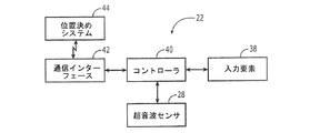
さらなる説明として、図6は、非破壊検査装置22の一実施形態のブロック図を示す。この実施形態において、非破壊検査装置22は、入力要素38を介してオペレータから入力を受け取るように構成されたコントローラ40を含む。加えて、コントローラ40は、超音波センサ28と通信するように更新されており、例えば、対応する入力要素38の作動に応答して超音波センサを作動させたり、及び超音波センサからの帰還信号の表示を受け取ったりする。この実施形態の非破壊検査装置22は、例えば、無線又は有線接続を介して、帰還信号に関連する情報をコンピュータ26に伝送する送信機を含む通信インターフェース42も含みうる。
As a further illustration, FIG. 6 shows a block diagram of one embodiment of a
図7に示すように、ワークピース24の非破壊検査方法は、超音波センサ28をワークピースと動作可能に接触するように配置することを含むことができる。工程50を参照。一実施形態では、まず、超音波センサ28を、ワークピース24上の所定の位置、例えば開始位置に配置する。ワークピース24上に非破壊検査装置22を配置する間、オペレータが非破壊検査装置をこれまでより人間工学的に操作できるように、オペレータの手のひらはグリップ30によって支持される。また、この実施形態の方法では、超音波センサがそれに対応する位置、例えば開始位置に配置される間、超音波センサ28からワークピース24中に超音波信号が発信される。工程54を参照。一実施形態では、オペレータはグリップ30の入力要素38を作動させることにより、超音波センサ28からワークピース24中への超音波信号の発信を開始する。工程52を参照。超音波センサ28による超音波信号の発信に応答して、超音波センサは帰還信号を受信する。工程56を参照。非破壊検査装置22上で帰還信号が格納、及び処理などされる間に、一実施形態の非破壊検査装置は、無線通信などを介してコンピュータ26に帰還信号に関する情報を供給することにより、コンピュータによる帰還信号の装置外処理、格納、及び/又は表示を支援する。工程58を参照。これに関して、オペレータがグリップ30の入力要素38を作動させると、コントローラ40は、通信インターフェース42を始動させて、コンピュータ26への帰還信号に関する情報の伝送を開始させることができる。帰還信号に関する情報は、ワークピースの厚み、ワークピースの検査対象部分内の異常などを含む、ワークピース24の様々な特徴に関連している。
As shown in FIG. 7, the non-destructive inspection method of the
ワークピース24の第1の所定位置(例えば、開始位置)の検査終了後、ワークピースに他の検査対象部分が残っているかどうかが決定される。工程60を参照。ワークピース24に他の検査対象部分が残っている場合、オペレータは、グリップ30に力を加えることにより、同じワークピース又は異なるワークピース上の第2の位置に、グリップと超音波センサ28とを同時に移動させることができる。図7の工程62を参照。次いで、ワークピース24上の複数の異なる位置の各々についてこのプロセスを繰り返し、所定の経路に沿って超音波センサを移動させ、例えば所定の検査経路に沿った複数の位置の各々においてワークピースを調べることにより、ワークピースをくまなく検査することができる。各位置における帰還信号の受信後、或いはワークピース上のすべての位置又は少なくとも複数の位置における帰還信号受信後にバッチ形式で、各位置において、超音波センサ28は帰還信号を受信することができ、非破壊検査装置22は帰還信号に関する情報をコンピュータ26に供給することができる。オペレータの手のひら(例えば手のひらの大部分)を支持するグリップ30を用いてオペレータが非破壊検査装置22と相互作用可能であることにより、例示的な一実施形態の非破壊検査装置は、オペレータの労力及び消耗を低減する人間工学的デバイスを提供し、それによりオペレータは、図1に示す小型の超音波センサ10を把持しなければならない場合と比較して、非破壊検査装置を長時間に亘って繰り返し使用することができる。
After the inspection of the first predetermined position (for example, the start position) of the
上述のように、ワークピース24上で非破壊検査装置22を手動で移動させることにより、ワークピースの複数の位置を検査することができる。オペレータは、検査する位置を特定することができる。別の構成では、非破壊検査装置22は、図6に示すような位置決めシステム44と通信することにより、検査位置を特定することができる。位置決めシステム44は様々に具現化することができる。しかしながら、一実施形態では、位置決めシステム44は、複数の全地球測位システム(GPS)の衛星、又は複数の擬似衛星、例えば検査が実行されている施設周辺に位置する複数の送受信機などである。この実施形態の位置決めシステム44は、非破壊検査装置22の通信インターフェース42と通信することにより位置決め信号を供給することができ、この信号は、コントローラ40又はコントローラと通信する位置決めモジュール(例えばGPSモジュール)によって処理される。位置決め信号に基づいて、コントローラ40又は関連の位置決めモジュールは、非破壊検査装置22の位置を決定することができる。したがって、この実施形態の通信インターフェース42は、コンピュータ26に帰還信号に関する情報を供給するだけでなく、位置決めシステム44によって供給された位置決め信号に基づいて帰還信号が捕獲された位置を特定することもできる。
As described above, by manually moving the
別の実施形態では、位置決めシステム44には、一又は複数のマーカ(例えば、照射点)をワークピース24に照射するプロジェク(例えば、レーザプロジェクタ)が含まれる。これに関して、まず、ワークピースに照射されるマーカが検査位置を示すように、プロジェクタのような位置決めシステム44をワークピース24と整列させて、較正する。マーカによって示された位置の一つにおいてワークピース24を検査するために、非破壊検査装置22をマーカと整列する位置まで移動させる。整列していることを確認するために、通信インターフェース42は受信機を含み、このような受信機は、例えばフォトダイオードであり、一実施形態では、位置決めシステム44によって供給されるレーザ信号のようなマーカを受信するためのレンズである。受信機がマーカを受信したら、コントローラ40は、受信機によって受信されたレーザ信号などの信号が所定の閾値を上回っていることを決定するのと同様に、非破壊検査装置22がワークピース24に対して適切に位置しており、そのときその下に位置するワークピースの部分を調べることができることを決定する。プロジェクタを含むこの実施形態の位置決めシステム44は様々に構成することができ、一実施形態では、複数の検査位置を規定するパターンにワークピース24を照射するように構成され、別の実施形態では、調査対象である第1の位置を規定する一つの第1マーカを、次いで第1の位置の検査に続いて別のマーカを、連続してワークピースに照射することにより、一つのマーカから次のマーカへとワークピースの検査を進行させるように構成される。
In another embodiment, the
一実施形態の位置決めシステム44には、複数のGPS衛星又は擬似衛星からの位置決め信号の供給と、プロジェクタによるワークピース24の照射とを含む、上述の実施形態の組み合わせが含まれる。この実施形態では、複数のGPS衛星又は擬似衛星からの位置決め信号により、非破壊検査装置22の大凡の位置決めが行われ、プロジェクタによるワークピース24の照射により、位置決めの精度又は粒度が向上する。位置決めシステム44の複数の実施例が提供されたが、非破壊検査装置22は、ワークピース24上の検査位置を特定する様々に異なる種類の位置決めシステムと相互作用することができる。
The
これらの実施形態に関連して、上述の説明及び添付図面に提示された教示の恩恵を有する本発明の多数の修正例及び他の実施形態が、当業者には想起されるであろう。したがって、本発明は開示した特定の実施形態に限定されるものでなく、修正例及び他の実施形態は、特許請求の範囲に含まれる。本明細書では特定の用語を使用しているが、それらは、一般的及び説明的な意味でのみ使用されているのであって、限定を目的として使用されているのではない。
下記の条項は、本開示のさらなる態様を記載する。
条項1.
非破壊検査装置(22)であって、
ワークピース(24)と動作可能に接触するように配置されて、ワークピース(24)中に超音波信号を発信し、このようにして発信された超音波信号に応答する帰還信号を受信する超音波センサ(28)、及び
超音波センサ(28)に対し、超音波センサ(28)と同時に動くように結合されたグリップ(30)であって、オペレータが非破壊検査装置(22)に加えた力がグリップ(30)を介して超音波センサ(28)に伝達されるようにオペレータの手のひらに適合してオペレータの手のひらを支持するグリップ(30)
を備えた非破壊検査装置(22)。
条項2.
異なるオペレータそれぞれの手のひらに適合するように構成された複数のグリップ(30)をさらに備えており、これら複数のグリップ(30)は超音波センサ(28)に交換可能に結合される、条項1に記載の非破壊検査装置(22)。
条項3.
グリップ(30)が、オペレータによって作動される少なくとも一つの入力要素(38)を備えている、条項1又は2に記載の非破壊検査装置(22)。
条項4.
位置決めシステム(44)と通信して検査位置を特定するように構成された通信インターフェース(42)をさらに備えている、条項1ないし3のいずれか一項に記載の非破壊検査装置(22)。
条項5.
通信インターフェース(42)が、非破壊検査装置(22)の位置を規定する位置決め信号、及び検査位置を示すマーカのうちの少なくとも一つを受信するように構成されている、条項4に記載の非破壊検査装置(22)。
条項6.
ワークピース(24)の非破壊検査方法であって、
ワークピース(24)と動作可能に接触するように超音波センサ(28)を配置すること、
超音波センサ(28)と動作可能に結合しているグリップ(30)によりオペレータの手のひらを支持すること、
超音波センサ(28)からワークピース(24)中へと超音波信号を発信すること、
上記のようにして発信された超音波信号に応答する帰還信号を受信すること、並びに
オペレータによってグリップ(30)に印加され、グリップ(30)を介して超音波センサ(28)に伝達される力に応答して、グリップ(30)と超音波センサ(28)とを同時に移動させること
を含む方法。
条項7.
グリップ(30)を、別のオペレータの手のひらに適合する別のグリップ(30)と交換することをさらに含む、条項6に記載の方法。
条項8.
グリップ(30)が入力要素(38)を含み、本方法が、オペレータによる入力要素(38)の作動に関する指示を入力要素(38)から受け取ることをさらに含む、条項6又は7に記載の方法。
条項9.
位置決めシステム(44)と通信して検査位置を特定することをさらに含む、条項6ないし8のいずれか一項に記載の方法。
条項10.
位置決めシステム(44)と通信することが、非破壊検査装置(22)の位置を規定する位置決め信号を受信すること、及び検査位置を示すマーカを受信することのうちの少なくとも一つを含む、条項9に記載の方法。
In connection with these embodiments, numerous modifications and other embodiments of the invention will occur to those skilled in the art that have the benefit of the teachings presented in the foregoing description and accompanying drawings. Accordingly, the invention is not limited to the specific embodiments disclosed, but modifications and other embodiments are within the scope of the claims. Although specific terms are used herein, they are used in a generic and descriptive sense only and not for purposes of limitation.
The following clauses describe further aspects of the present disclosure.
Article 1.
A non-destructive inspection device (22),
An ultrasound transducer disposed in operative contact with the workpiece (24) for transmitting an ultrasonic signal in the workpiece (24) and receiving a feedback signal in response to the ultrasonic signal thus transmitted. A grip (30) coupled to the ultrasonic sensor (28) and the ultrasonic sensor (28) to move simultaneously with the ultrasonic sensor (28), which the operator added to the non-destructive inspection device (22) A grip (30) that conforms to and supports the operator's palm so that force is transmitted to the ultrasonic sensor (28) via the grip (30).
A nondestructive inspection device (22).
Article 2.
In clause 1, further comprising a plurality of grips (30) configured to fit in the palm of each of the different operators, the plurality of grips (30) being interchangeably coupled to the ultrasonic sensor (28). The nondestructive inspection device (22) described.
Article 3.
Nondestructive inspection device (22) according to clause 1 or 2, wherein the grip (30) comprises at least one input element (38) actuated by an operator.
Article 4.
The nondestructive inspection device (22) of any one of clauses 1 to 3, further comprising a communication interface (42) configured to communicate with the positioning system (44) to identify an inspection location.
Article 5.
The non-description of clause 4, wherein the communication interface (42) is configured to receive at least one of a positioning signal defining a position of the non-destructive inspection device (22) and a marker indicating the inspection position. Destructive inspection device (22).
Article 6.
A non-destructive inspection method for a workpiece (24),
Placing an ultrasonic sensor (28) in operative contact with the workpiece (24);
Supporting the palm of the operator by a grip (30) operatively associated with the ultrasonic sensor (28);
Transmitting an ultrasonic signal from the ultrasonic sensor (28) into the workpiece (24);
Receiving a feedback signal in response to the ultrasonic signal transmitted as described above, and the force applied to the grip (30) by the operator and transmitted to the ultrasonic sensor (28) via the grip (30) Responsive to moving the grip (30) and the ultrasonic sensor (28) simultaneously.
Article 7.
The method of clause 6, further comprising replacing the grip (30) with another grip (30) that fits in the palm of another operator.
Article 8.
The method of clause 6 or 7, wherein the grip (30) includes an input element (38), and the method further comprises receiving instructions from the input element (38) regarding operation of the input element (38) by an operator.
Article 9.
9. The method of any one of clauses 6 to 8, further comprising communicating with a positioning system (44) to identify an inspection location.
The clause, wherein communicating with the positioning system (44) includes at least one of receiving a positioning signal defining a position of the non-destructive inspection device (22) and receiving a marker indicating the inspection position. 9. The method according to 9.
10 超音波センサ
20 非破壊検査システム
22 非破壊検査装置
24 ワークピース
26 コンピュータ
28 超音波センサ
30 グリップ
32 グリップ表面
34 ばね
36 吸着デバイス
DESCRIPTION OF
Claims (9)
ワークピース(24)と動作可能に接触するように配置されて、前記ワークピース(24)中に超音波信号を発信し、このようにして発信された前記超音波信号に応答する帰還信号を受信する超音波センサ(28)と、
前記超音波センサ(28)と同時に動くように前記超音波センサ(28)に動作可能に結合されたグリップ(30)であって、オペレータが前記非破壊検査装置(22)に加えた力が前記グリップ(30)を介して前記超音波センサ(28)に伝達されるように前記オペレータの手のひらに適合して前記オペレータの手のひらを支持するグリップ(30)と、
レーザプロジェクタを含む位置決めシステム(44)と通信して検査位置を特定するように構成されているとともに、前記レーザプロジェクタが照射した前記検査位置を示すマーカを受信するよう構成された通信インターフェース(42)と、
を備えた非破壊検査装置(22)。 A non-destructive inspection device (22),
Is placed in contact operable with the workpiece (24), said originated the work piece (24) ultrasonic signals during the receive feedback signal in response to this way originating on the ultrasonic signal An ultrasonic sensor (28) to perform,
Wherein A operably coupled grip to the ultrasonic sensor to move simultaneously with the ultrasonic sensor (28) (28) (30), the force the operator is added to the nondestructive inspection apparatus (22) a grip (30) via said grip (30) to conform to the palm of the operator so as to be transmitted to the ultrasonic sensor (28) for supporting the palm of the operator,
Together they are configured to communicate with a positioning system including a laser projector (44) for specifying the inspection position, a communication interface in which the laser projector is configured to receive a marker indicating the inspection position irradiated (42) When,
A nondestructive inspection device (22).
前記ワークピース(24)と動作可能に接触するように超音波センサ(28)を配置すること、
前記超音波センサ(28)と動作可能に結合しているグリップ(30)によりオペレータの手のひらを支持すること、
レーザプロジェクタを含む位置決めシステム(44)と通信し、前記レーザプロジェクタが照射した検査位置を示すマーカを受信して前記検査位置を特定すること、
前記超音波センサ(28)から前記ワークピース(24)中へと超音波信号を発信すること、
前記発信された超音波信号に応答する帰還信号を受信すること、並びに
前記オペレータによって前記グリップ(30)に印加され、前記グリップ(30)を介して前記超音波センサ(28)に伝達される力に応答して、前記グリップ(30)と前記超音波センサ(28)とを同時に移動させること
を含む方法。 A non-destructive inspection method for a workpiece (24),
It said workpiece (24) and operatively contacting manner disposing the ultrasonic sensor (28),
Wherein supporting the palm of an operator by gripping which is operatively coupled to the ultrasonic sensor (28) (30),
Communication and positioning systems (44) including a laser projector, to identify the inspection position by receiving a marker indicating the inspection position where the laser projector irradiates it,
Wherein from the ultrasonic sensor (28) to said workpiece (24) in that transmits an ultrasonic signal,
Receiving a feedback signal responsive to said outgoing ultrasonic signal, and
Wherein is applied to the grip (30) by an operator, said through said grip (30) in response to a force transmitted to the ultrasonic sensor (28), wherein the ultrasonic sensor and the grip (30) (28) And moving at the same time.
Applications Claiming Priority (2)
| Application Number | Priority Date | Filing Date | Title |
|---|---|---|---|
| US13/298,325 | 2011-11-17 | ||
| US13/298,325 US9057686B2 (en) | 2011-11-17 | 2011-11-17 | Non-destructive inspection apparatus having an ergonomic grip and associated method |
Publications (3)
| Publication Number | Publication Date |
|---|---|
| JP2013108982A JP2013108982A (en) | 2013-06-06 |
| JP2013108982A5 JP2013108982A5 (en) | 2016-01-21 |
| JP6157840B2 true JP6157840B2 (en) | 2017-07-05 |
Family
ID=47257481
Family Applications (1)
| Application Number | Title | Priority Date | Filing Date |
|---|---|---|---|
| JP2012252496A Expired - Fee Related JP6157840B2 (en) | 2011-11-17 | 2012-11-16 | Nondestructive inspection device with ergonomic grip and related methods |
Country Status (6)
| Country | Link |
|---|---|
| US (1) | US9057686B2 (en) |
| EP (1) | EP2594934B1 (en) |
| JP (1) | JP6157840B2 (en) |
| CN (1) | CN103123337B (en) |
| BR (1) | BR102012029193B1 (en) |
| CA (1) | CA2792703C (en) |
Families Citing this family (4)
| Publication number | Priority date | Publication date | Assignee | Title |
|---|---|---|---|---|
| US9945939B1 (en) * | 2013-05-06 | 2018-04-17 | Lokdon Llc | Method for determining a location of an emitter |
| DE102014103945A1 (en) * | 2014-03-21 | 2015-09-24 | Ge Sensing & Inspection Technologies Gmbh | Device for non-destructive ultrasonic testing of workpieces with improved handling and method therefor |
| CN105784515A (en) * | 2015-12-08 | 2016-07-20 | 四川大学 | Vacuum ultrasonic vibration fatigue experimental system |
| CN109435542A (en) * | 2018-09-17 | 2019-03-08 | 苏州涵轩信息科技有限公司 | Retractable compasses ruler |
Family Cites Families (16)
| Publication number | Priority date | Publication date | Assignee | Title |
|---|---|---|---|---|
| JPH05142213A (en) * | 1991-11-20 | 1993-06-08 | Osaka Gas Co Ltd | Probe holder of ultrasonic-wave measuring apparatus and ultrasonic-wave measuring apparatus |
| JPH09276267A (en) * | 1996-04-16 | 1997-10-28 | Ge Yokogawa Medical Syst Ltd | Grip cap for ultrasonic probe, and ultrasonic probe |
| US5897503A (en) | 1997-08-01 | 1999-04-27 | Acuson Corporation | Ultrasound transducer probe having case handle grip surfaces |
| JP3107298B2 (en) * | 1998-02-20 | 2000-11-06 | 日本電気株式会社 | Mouse type information input device |
| DE10300383B4 (en) * | 2003-01-09 | 2005-05-12 | Windhoff Bahn- Und Anlagentechnik Gmbh | Pipeline pig |
| WO2005038449A1 (en) * | 2003-10-16 | 2005-04-28 | Commonwealth Scientific And Industrial Research Organisation | A probe for non-destructive testing |
| US7222514B2 (en) | 2004-06-21 | 2007-05-29 | The Boeing Company | Laminate material testing methods and systems |
| US20060173331A1 (en) * | 2004-11-24 | 2006-08-03 | Siemens Medical Solutions Usa, Inc. | Ergonomic transducer housing and methods for ultrasound imaging |
| JP2006184028A (en) * | 2004-12-24 | 2006-07-13 | Chugoku Electric Power Co Inc:The | Self-running robot used in auscultatory inspection |
| CN1956636B (en) * | 2005-10-26 | 2010-09-29 | 鸿富锦精密工业(深圳)有限公司 | Electronic device with changable case |
| US7478569B2 (en) | 2005-12-02 | 2009-01-20 | The Boeing Company | Non-destructive inspection system with flexible display and associated method |
| EP1935343B1 (en) * | 2006-12-18 | 2011-10-26 | Esaote S.p.A. | Ergonomic housing for electroacoustic transducers and ultrasound probe with said housing |
| JP5582689B2 (en) * | 2007-09-21 | 2014-09-03 | 東芝プラントシステム株式会社 | Ultrasonic inspection apparatus, ultrasonic probe apparatus used in ultrasonic inspection apparatus, and ultrasonic inspection method |
| US8100015B2 (en) * | 2007-11-20 | 2012-01-24 | Kabushiki Kaisha Toshiba | Ultrasonic inspection apparatus and ultrasonic probe used for same |
| JP5422464B2 (en) * | 2010-03-31 | 2014-02-19 | 中日本ハイウェイ・エンジニアリング名古屋株式会社 | Blow inspection device |
| CN202488512U (en) * | 2012-02-23 | 2012-10-10 | 丁绍杰 | Modified mobile phone portable power source structure |
-
2011
- 2011-11-17 US US13/298,325 patent/US9057686B2/en not_active Expired - Fee Related
-
2012
- 2012-10-16 CA CA2792703A patent/CA2792703C/en active Active
- 2012-11-12 EP EP12192219.9A patent/EP2594934B1/en active Active
- 2012-11-14 BR BR102012029193-2A patent/BR102012029193B1/en not_active IP Right Cessation
- 2012-11-16 JP JP2012252496A patent/JP6157840B2/en not_active Expired - Fee Related
- 2012-11-19 CN CN201210468043.3A patent/CN103123337B/en not_active Expired - Fee Related
Also Published As
| Publication number | Publication date |
|---|---|
| CN103123337B (en) | 2017-10-13 |
| CA2792703A1 (en) | 2013-05-17 |
| US20130125657A1 (en) | 2013-05-23 |
| BR102012029193B1 (en) | 2020-11-10 |
| EP2594934A2 (en) | 2013-05-22 |
| BR102012029193A2 (en) | 2013-10-08 |
| US9057686B2 (en) | 2015-06-16 |
| CA2792703C (en) | 2018-10-09 |
| EP2594934B1 (en) | 2020-08-12 |
| EP2594934A3 (en) | 2015-03-25 |
| CN103123337A (en) | 2013-05-29 |
| JP2013108982A (en) | 2013-06-06 |
Similar Documents
| Publication | Publication Date | Title |
|---|---|---|
| JP6157840B2 (en) | Nondestructive inspection device with ergonomic grip and related methods | |
| US10126271B2 (en) | Apparatus and method for non-destructive testing of materials | |
| EP3069132B1 (en) | Structural bond inspection | |
| US8983794B1 (en) | Methods and systems for non-destructive composite evaluation and repair verification | |
| JP6313931B2 (en) | Surface visualization system to show inconsistencies | |
| EP1431755B2 (en) | Ultrasonic thermography inspection method and apparatus | |
| EP1709438B1 (en) | Non-destructive inspection device for inspecting limited-acces features of a structure | |
| JP5856624B2 (en) | X-ray inspection tool | |
| US6484583B1 (en) | Through-transmission ultrasonic inspection apparatus and method | |
| RU2464557C2 (en) | Portable scanning device for metallurgical nondestructive inspection | |
| US8185327B2 (en) | Monitoring of composite materials | |
| CN101003307A (en) | Airplane body checking method and device | |
| KR101564645B1 (en) | Couplant pad for ultrasonic transducer and ultrasonic meter using the same of | |
| JP2013108982A5 (en) | ||
| US20160011152A1 (en) | Nondestructive Inspection Using Acousto-Optics | |
| JP2016514848A (en) | Ultrasonic inspection using incident angle | |
| KR920004755B1 (en) | Contact ultrasonic transducer head | |
| GB2425228A (en) | Non destructive testing inspection apparatus for three dimensional objects | |
| Bach et al. | Damage Introduction, Detection, and Assessment at CFRP Door Surrounding Panel | |
| JPH02227658A (en) | Detector for partial discharge | |
| Mattei et al. | Real-time defect imaging in plate-like structures using a portable Guided Wave Sparse Array in direct non-glued contact |
Legal Events
| Date | Code | Title | Description |
|---|---|---|---|
| A621 | Written request for application examination |
Free format text: JAPANESE INTERMEDIATE CODE: A621 Effective date: 20151110 |
|
| A521 | Request for written amendment filed |
Free format text: JAPANESE INTERMEDIATE CODE: A523 Effective date: 20151126 |
|
| A977 | Report on retrieval |
Free format text: JAPANESE INTERMEDIATE CODE: A971007 Effective date: 20160823 |
|
| A131 | Notification of reasons for refusal |
Free format text: JAPANESE INTERMEDIATE CODE: A131 Effective date: 20160913 |
|
| A521 | Request for written amendment filed |
Free format text: JAPANESE INTERMEDIATE CODE: A523 Effective date: 20161213 |
|
| TRDD | Decision of grant or rejection written | ||
| A01 | Written decision to grant a patent or to grant a registration (utility model) |
Free format text: JAPANESE INTERMEDIATE CODE: A01 Effective date: 20170523 |
|
| A61 | First payment of annual fees (during grant procedure) |
Free format text: JAPANESE INTERMEDIATE CODE: A61 Effective date: 20170607 |
|
| R150 | Certificate of patent or registration of utility model |
Ref document number: 6157840 Country of ref document: JP Free format text: JAPANESE INTERMEDIATE CODE: R150 |
|
| R250 | Receipt of annual fees |
Free format text: JAPANESE INTERMEDIATE CODE: R250 |
|
| R250 | Receipt of annual fees |
Free format text: JAPANESE INTERMEDIATE CODE: R250 |
|
| R250 | Receipt of annual fees |
Free format text: JAPANESE INTERMEDIATE CODE: R250 |
|
| LAPS | Cancellation because of no payment of annual fees |