JP6157626B2 - Toggle switch lockout clip and method - Google Patents
Toggle switch lockout clip and method Download PDFInfo
- Publication number
- JP6157626B2 JP6157626B2 JP2015530161A JP2015530161A JP6157626B2 JP 6157626 B2 JP6157626 B2 JP 6157626B2 JP 2015530161 A JP2015530161 A JP 2015530161A JP 2015530161 A JP2015530161 A JP 2015530161A JP 6157626 B2 JP6157626 B2 JP 6157626B2
- Authority
- JP
- Japan
- Prior art keywords
- toggle switch
- clip
- switch
- toggle
- cover
- Prior art date
- Legal status (The legal status is an assumption and is not a legal conclusion. Google has not performed a legal analysis and makes no representation as to the accuracy of the status listed.)
- Active
Links
- 238000000034 method Methods 0.000 title claims description 20
- 239000012858 resilient material Substances 0.000 description 3
- 238000011900 installation process Methods 0.000 description 2
- 239000000463 material Substances 0.000 description 2
- 238000000465 moulding Methods 0.000 description 2
- 239000004677 Nylon Substances 0.000 description 1
- 229910000831 Steel Inorganic materials 0.000 description 1
- 229920000122 acrylonitrile butadiene styrene Polymers 0.000 description 1
- 239000000956 alloy Substances 0.000 description 1
- 229910045601 alloy Inorganic materials 0.000 description 1
- 238000013459 approach Methods 0.000 description 1
- 238000005266 casting Methods 0.000 description 1
- 239000012943 hotmelt Substances 0.000 description 1
- 238000009434 installation Methods 0.000 description 1
- 230000002452 interceptive effect Effects 0.000 description 1
- 238000003475 lamination Methods 0.000 description 1
- 238000012423 maintenance Methods 0.000 description 1
- 239000002184 metal Substances 0.000 description 1
- 238000012986 modification Methods 0.000 description 1
- 230000004048 modification Effects 0.000 description 1
- 229920001778 nylon Polymers 0.000 description 1
- 239000004417 polycarbonate Substances 0.000 description 1
- 229920000515 polycarbonate Polymers 0.000 description 1
- 238000012827 research and development Methods 0.000 description 1
- 238000000110 selective laser sintering Methods 0.000 description 1
- 239000010959 steel Substances 0.000 description 1
- 238000003466 welding Methods 0.000 description 1
Images


Classifications
-
- H—ELECTRICITY
- H01—ELECTRIC ELEMENTS
- H01H—ELECTRIC SWITCHES; RELAYS; SELECTORS; EMERGENCY PROTECTIVE DEVICES
- H01H9/00—Details of switching devices, not covered by groups H01H1/00 - H01H7/00
- H01H9/20—Interlocking, locking, or latching mechanisms
- H01H9/28—Interlocking, locking, or latching mechanisms for locking switch parts by a key or equivalent removable member
- H01H9/287—Interlocking, locking, or latching mechanisms for locking switch parts by a key or equivalent removable member wherein the operating part is made inaccessible or more difficult to access by a lid, cover or guard, e.g. lockable covers
-
- H—ELECTRICITY
- H01—ELECTRIC ELEMENTS
- H01H—ELECTRIC SWITCHES; RELAYS; SELECTORS; EMERGENCY PROTECTIVE DEVICES
- H01H9/00—Details of switching devices, not covered by groups H01H1/00 - H01H7/00
- H01H9/20—Interlocking, locking, or latching mechanisms
- H01H9/28—Interlocking, locking, or latching mechanisms for locking switch parts by a key or equivalent removable member
- H01H9/286—Interlocking, locking, or latching mechanisms for locking switch parts by a key or equivalent removable member making use of a removable locking part acting directly on the operating part
Description
本出願は、トグルスイッチに関し、かつより具体的には、トグルスイッチを望ましい状態に固定するための装置及び方法に関する。 This application relates to toggle switches, and more specifically to an apparatus and method for locking a toggle switch in a desired state.
トグルスイッチは、様々な電気システムを作動させるために使用される。1つの一般的な用途において、トグルスイッチは、航空機の様々な操縦翼面電気システムの電源をオン及びオフするために使用される。例えば、航空機のエルロンを制御するのに先立って、エルロンに関連する操縦翼面電気システムは、関連するトグルスイッチを「オン」位置へ移動させることによって、電源をオンにすることが必要である。 Toggle switches are used to activate various electrical systems. In one common application, toggle switches are used to turn on and off the various control surface electrical systems of an aircraft. For example, prior to controlling the aileron of an aircraft, the control surface electrical system associated with the aileron needs to be powered on by moving the associated toggle switch to the “on” position.
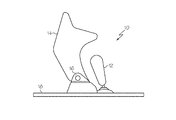
図1及び2を参照すると、典型的なトグルスイッチアセンブリ10は、トグルスイッチ12、スイッチカバー14、ファルクラム(fulcrum)16、及びスイッチボード18を含む。トグルスイッチ12及びファルクラム16は、スイッチボード18に設置される。トグルスイッチ12は、図1に示されるような「オン」(例えば、前方)位置と、図2に示されるような「オフ」(例えば、後方)位置との間で移動可能である。スイッチカバー14は、ファルクラム16に対して回転可能に接続され、かつクローズ位置(図1)とオープン位置(図2)との間で移動可能である。スイッチカバー14は、図1において示されるように、スイッチカバー14がクローズ位置へ移動される場合、トグルスイッチ12を前方の「オン」位置に自動的に移動させるように構成される。それ故、トグルスイッチアセンブリ10は、電源オンの構成へ付勢される。トグルスイッチアセンブリ10を電源オフにするために、ユーザ(例えば、パイロット)は、図2において示されるように、スイッチカバー14を開いて、かつトグルスイッチ12を後方の「オフ」位置へ移動させなければならない。
With reference to FIGS. 1 and 2, a typical
航空機の保守の間に、トグルスイッチアセンブリ10は電源がオフされ、それによって関連する操縦翼面電気システムに対する電力供給を切断する。しかしながら、スイッチカバー14が不注意にクローズ位置へ移動される場合、その後、電力は関連する操縦翼面電気システムに対して自動的に回復される。
During aircraft maintenance,
したがって、当業者は、トグルスイッチの分野において研究及び開発の努力を継続している。 Accordingly, those skilled in the art continue research and development efforts in the field of toggle switches.
一実施形態において、開示されるトグルスイッチのロックアウトクリップは、中央領域を有しかつ中央領域から突出するラッチ部を含むクリップ本体であって、ラッチ部が延伸部材、及び延伸部材に接続されフックギャップを画定するフック部材を含み、並びにラッチ部から離れるように中央領域から突出するレッグ部を含む、クリップ本体を含み得る。 In one embodiment, the disclosed toggle switch lockout clip is a clip body having a central region and including a latch portion protruding from the central region, the latch portion being connected to the extension member and the extension member and the hook A clip body may be included that includes a hook member that defines a gap and includes a leg portion that protrudes from the central region away from the latch portion.
別の実施形態において、開示されるトグルスイッチのロックアウトクリップは、中央領域を有しかつ中央領域から突出するラッチ部を含むクリップ本体であって、ラッチ部が延伸部材及び延伸部材に接続されフックギャップをするフック部材を含み、ラッチ部から離れるように中央領域から突出するレッグ部、第2の側部と対向する第1の側部において、第1及び2の側部は中央領域から延伸しかつそれらの間のギャップを画定する、第1の側部、並びに第1及び2の側部の間に位置決めされる係合部を含む、クリップ本体を含み得る。 In another embodiment, the disclosed toggle switch lockout clip is a clip body having a central region and including a latch portion protruding from the central region, wherein the latch portion is connected to the extension member and the extension member and hooked. The first and second side portions extend from the central region in the first side portion that includes a hook member that forms a gap and protrudes from the central region so as to be separated from the latch portion, and the second side portion. And a clip body including a first side and an engagement portion positioned between the first and second sides defining a gap therebetween.
別の実施形態において、開示されるトグルスイッチシステムは、(1)トグルスイッチ及び少なくともクローズ位置とオープン位置との間で移動可能なスイッチカバーを含むトグルスイッチアセンブリであって、スイッチカバーはクローズ位置においてトグルスイッチの上に位置決めされる、トグルスイッチアセンブリ、並びに(2)中央領域を有するクリップ本体であって、クリップ本体は中央領域から突出するラッチ部において、ラッチ部はフックギャップを画定し、かつスイッチカバーの少なくとも一部がフックギャップの中に受け入れられる、ラッチ部、及びラッチ部から離れるように中央領域から突出するレッグ部を含む、クリップ本体を含む、トグルスイッチのロックアウトクリップを含み得る。 In another embodiment, the disclosed toggle switch system is (1) a toggle switch assembly including a toggle switch and a switch cover that is movable at least between a closed position and an open position, wherein the switch cover is in the closed position. A toggle switch assembly positioned on the toggle switch, and (2) a clip body having a central region, wherein the clip body is a latch portion protruding from the central region, the latch portion defining a hook gap, and the switch A toggle switch lockout clip may be included, including a clip body including a latch portion and a leg portion protruding from the central region away from the latch portion, at least a portion of the cover being received in the hook gap.
さらに別の実施形態において、トグルスイッチ及びスイッチカバーを含むトグルスイッチアセンブリをロックアウトするための方法であって、トグルスイッチがオン位置とオフ位置との間で移動可能であり、かつスイッチカバーがクローズ位置とオープン位置との間で移動可能である、方法が開示される。方法は、(1)スイッチカバーをオープン位置に移動させ、かつトグルスイッチをオフ位置に移動させるステップ、並びに(2)トグルスイッチアセンブリにクリップを設置するステップであって、クリップがスイッチカバーにラッチするラッチ部及びラッチ部から離れるように延伸するレッグ部を含み、クリップがスイッチカバーのクローズ位置への移動及びトグルスイッチのオン位置への移動を抑制する、ステップを含み得る。 In yet another embodiment, a method for locking out a toggle switch assembly including a toggle switch and a switch cover, wherein the toggle switch is movable between an on position and an off position, and the switch cover is closed. A method is disclosed that is movable between a position and an open position. The method includes (1) moving the switch cover to the open position and moving the toggle switch to the off position, and (2) installing the clip on the toggle switch assembly, the clip latching on the switch cover. A leg portion extending away from the latch portion and the latch portion, and the clip may include a step of suppressing movement of the switch cover to a closed position and movement of a toggle switch to an on position.
開示されるトグルスイッチのロックアウトクリップ及び方法は、以下の詳細な説明、添付の図面、及び添付の特許請求の範囲から明らかになるだろう。 The disclosed toggle switch lockout clip and method will become apparent from the following detailed description, the accompanying drawings, and the appended claims.
トグルスイッチアセンブリの不注意な作動を(排除できない場合)抑制するために、トグルスイッチアセンブリに設置され得るトグルスイッチのロックアウトクリップが開示される。トグルスイッチアセンブリに設置される場合、開示されるトグルスイッチのロックアウトクリップは、トグルスイッチアセンブリのトグルスイッチをオフ位置に固定し、かつトグルスイッチアセンブリのスイッチカバーをオープン位置に固定することができる。そのようにして、トグルスイッチアセンブリの作動は、作動に先立ってトグルスイッチのロックアウトクリップを除去する、意図的かつ積極的なステップを必要とする。 To suppress inadvertent actuation of the toggle switch assembly (if it cannot be eliminated), a toggle switch lockout clip is disclosed that may be installed in the toggle switch assembly. When installed in a toggle switch assembly, the disclosed toggle switch lockout clip can lock the toggle switch assembly toggle switch in the off position and the toggle switch assembly switch cover in the open position. As such, actuation of the toggle switch assembly requires a deliberate and aggressive step of removing the toggle switch lockout clip prior to actuation.
図3及び4を参照すると、開示されるトグルスイッチのロックアウトクリップの一実施形態は、概して100として指定され、ラッチ部104、レッグ部106、係合部108、及び側部110、112を有するクリップ本体102を含み得る。貫通孔114などの付加的な構成要素及び特徴は、本開示の範囲から逸脱することなく、含まれ得る。
Referring to FIGS. 3 and 4, one embodiment of the disclosed toggle switch lockout clip is designated generally as 100 and has a
クリップ本体102は、半剛体で伸縮性がありさらに弾力性がある材料から形成され得、トグルスイッチのロックアウトクリップ100をトグルスイッチアセンブリに設置することを容易にしている。一実施例として、トグルスイッチのロックアウトクリップ100のクリップ本体102は、金属又はスチールなどの合金から形成され得る。別の実施例として、トグルスイッチのロックアウトクリップ100のクリップ本体102は、ポリカーボネートなどの高分子材料から形成され得る。さらに別の実施例として、トグルスイッチのロックアウトクリップ100のクリップ本体102は、材料の組み合わせから形成され得る。
The
トグルスイッチのロックアウトクリップ100のクリップ本体102は、単一のモノリシックの本体として形成され得る(すなわち、ラッチ部104、レッグ部106、係合部108、及び側部110、112は、統合され得る)。モールディング、キャスティング、スタンピング、熱溶解積層法(例えば、ABSプラスチックを伴って)、選択的レーザー焼結(例えば、ナイロン)、及び/又は同様なものなどの様々な成形技術は、モノリシックのクリップ本体を構築するために使用され得る。代替的に、トグルスイッチのロックアウトクリップ100のクリップ本体102は、クリップ本体102の1以上の部104、106、108、110、112を一緒に接続することによって形成され得る(例えば、溶接、接着、機械的留め具)。
The
クリップ本体102のラッチ部104は、クリップ本体102の中央領域116から離れるように突出し得、かつ延伸部材118及びフック部材120を含み得る。延伸部材118は、近位端122及び遠位端124を含み得る。延伸部材118の近位端122は、クリップ本体102の中央領域116の近傍(すなわち、そこ又は近く)において位置決めされ得る。フック部材120は、延伸部材118の遠位端124の近傍に接続され得、かつ延伸部材118に関して角度Aにおいて配置され得る。角度Aは、クリップ本体102の中央領域に向かってオープンし得、かつ約45度から約135度、又は約70度から約110度(例えば、約90度)などのように、約10度から約170度の範囲に含まれ得る。それ故、フック部材120は、延伸部材118の遠位端124の近傍において、フック部材120と延伸部材118との間のフックギャップ126を画定し得る。フックギャップ126は、図5において示されるように、スイッチカバー204の先端を密接に受け入れるように形作られ得る。
The
随意に、ガイドタブ128が、ラッチ部104のフック部材120の端部130(図4)から延伸し得る。ガイドタブ128は、フック部材120に関してゼロではない角度B(図4)において配置され得、かつラッチ部104のフックギャップ126に向かって延伸するカミング表面132を含み得る。例えば、ガイドタブ128の角度Bは、約20度から約90度、又は約30度から約60度(例えば、約45度)などのように、約10度から約180度の範囲に含まれ得る。
Optionally, a
クリップ本体102のレッグ部106は、クリップ本体102の中央領域116から離れるように、概してラッチ部104から離れる方向に突出し得る。レッグ部106は、近位端134及び遠位端136を含み得る。レッグ部106の近位端134は、クリップ本体102の中央領域116の近傍に位置決めされ得、かつ遠位端136は、近位端134から距離Dの間隔を有し得る。距離Dは、レッグ部106の高さを画定し得、かつ以下に詳細に説明されるように、トグルスイッチのロックアウトクリップ100が設置される、トグルスイッチアセンブリのサイズ及び構成によって決定され得る。
The
クリップ本体102の係合部108は、係合部108が概してラッチ部104とレッグ部106との間にあるように、クリップ本体102の中央領域116から内側へ突出し得る。係合部108は、以下に詳細に説明されるように、トグルスイッチのロックアウトクリップ100が設置される、トグルスイッチアセンブリのトグルスイッチ及びスイッチカバーを係合させる(又は、少なくとも接近させる)ための係合表面140を含み得る。ノッチ142が係合表面140の中に形成され得、かつノッチ142は、トグルスイッチ(又はスイッチカバー)の一部の輪郭に密接に対応するように形作られ得る。
The
第1の側部110は、第2の側部112から横方向に対向する位置に置かれ得、かつ随意に、第2の側部112と概して平行であり得る。それ故、第1及び2の側部110、112はギャップ144を画定し得、かつ係合部108は、ギャップ144の中に位置決めされ得、かつ第1及び2の側部110、112の間で横方向に延伸し得る。第1及び2の側壁110、112の間の横方向の間隔(すなわち、ギャップ144の幅)は、以下に詳細に説明されるように、トグルスイッチのロックアウトクリップ100が設置される、トグルスイッチアセンブリのスイッチカバーの少なくとも一部を受け入れるために十分であり得る。
The
クリップ本体102の中央領域116は、貫通孔114を画定し得る。貫通孔114は、クリップ本体102の第1のサイド146からクリップ本体102の第2のサイド148へ、横方向に延伸し得る。それ故、図6において示されるように、タグ150は、テザー(tether)152(例えば、ピン、コード、ワイヤー、クリップ、ロック、又は同様なもの)を、スイッチ本体の中の貫通孔114を通り抜けさせることによって、トグルスイッチのロックアウトクリップ100に接続され得る。タグは、文章(例えば、「取り除くな」)、色(例えば、赤色)、及び/又はグラフィックスなどの印を含み得、他者にトグルスイッチのロックアウトクリップ100を取り除かないように、又はさもなければトグルスイッチのロックアウトクリップ100を許可なく触らないように警告する。
A
今度は図5を参照すると、開示されるトグルスイッチのロックアウトクリップ100は、トグルスイッチアセンブリ200に設置され得、トグルスイッチアセンブリ200の不注意な作動を(排除できなければ)抑制する。1つの具体的なトグルスイッチアセンブリ(アセンブリ200)が以下に説明される一方で、当業者は、開示されるトグルスイッチのロックアウトクリップ100が、本開示の範囲から逸脱することなしに様々なトグルスイッチアセンブリの使用に対して構成され得ることを理解するだろう。
Referring now to FIG. 5, the disclosed toggle
トグルスイッチアセンブリ200は、トグルスイッチ202、スイッチカバー204、ファルクラム206、スイッチボード208、及び随意にストップ210を含み得る。トグルスイッチ202、ファルクラム206、及びストップ210は、スイッチボード208に設置され得る。トグルスイッチ202は、少なくとも「オン」位置(図1を見よ)と「オフ」位置との間で移動可能である。「オフ」位置において、トグルスイッチ202は、トグルスイッチ202の軸Tが垂直軸Vに関して角度P(例えば、約5から約45度の間)にある、後方の位置にあり得る。
The
スイッチカバー204は、ファルクラム206に対して回転可能に接続され得、かつクローズ位置(図1を見よ)とオープン位置との間で移動可能である。スイッチカバー204がオープン位置にある場合、トグルスイッチ202は、後方(すなわち、「オフ」)位置に移動可能である。
The
トグルスイッチアセンブリ200が「オフ」構成にある場合(例えば、スイッチカバー204がオープンで、かつトグルスイッチ202が後方位置にある)、トグルスイッチのロックアウトクリップ100は、以下に説明されるようにトグルスイッチアセンブリ200に設置され得る。トグルスイッチのロックアウトクリップ100をトグルスイッチアセンブリ200に設置するための他の技術がまた、熟考されている。
When the
先ず、クリップ本体102のレッグ部106は、レッグ部106の遠位端136がトグルスイッチ202と随意のストップ210との間に位置決めされるように、スイッチボード208に配置され得る。トグルスイッチのロックアウトクリップ100が十分に設置される場合、レッグ部106の遠位端136は、随意のストップ210に隣接する。
First, the
次に、トグルスイッチのロックアウトクリップ100は、トグルスイッチアセンブリ200のトグルスイッチ202及びスイッチカバー204に位置合わせされる。具体的に、トグルスイッチのロックアウトクリップ100は、クリップ本体102の係合部108(図3及び4)がトグルスイッチ202と位置合わせされ、かつ第1及び2の側部110、112の間のギャップ144がスイッチカバー204の一部を受け入れるように位置合わせされるように、位置合わせされ得る。
The toggle
スイッチボード208の上にレッグ部106があり、かつトグルスイッチのロックアウトクリップ100が位置合わせされた場合、クリップ本体102のラッチ部104は、矢印Mによって示される方向へ促され得る。ラッチ部104が矢印Mの方向へ移動する際、スイッチカバー204の先端205は、スイッチカバー204の先端205がラッチ部104のフック部材120と延伸部材118との間のフックギャップ126の中に位置決めされるまで、ガイドタブ128のカミング表面132に沿ってカムし得る。
When the
設置のプロセスは、一旦、トグルスイッチのロックアウトクリップ100のラッチ部104が、トグルスイッチアセンブリ200のスイッチカバー204に適正にラッチすると、完了し得る。伸縮性、弾力性がある材料からクリップ本体102を形成することは、ラッチ部104がスイッチカバー204にラッチするプロセスを容易にし得る。
The installation process can be completed once the
したがって、一旦、トグルスイッチのロックアウトクリップ100がトグルスイッチアセンブリ200に設置されると、トグルスイッチのロックアウトクリップ100は、トグルスイッチ202を「オフ」位置に固定し、かつスイッチカバー204をオープン位置に固定する。具体的に、一旦、トグルスイッチのロックアウトクリップ100がトグルスイッチアセンブリ200に設置されると、トグルスイッチのロックアウトクリップ100の係合部108(図3及び4)は、トグルスイッチアセンブリ200のトグルスイッチ202及びスイッチカバー204に向かって突出し得、トグルスイッチ202の「オン」位置への移動を抑制し得、かつクローズ位置へのスイッチカバー204の移動を抑制し得る、干渉する障害物を生み出す。
Thus, once the toggle
トグルスイッチ及びスイッチカバーを含むトグルスイッチアセンブリをロックアウトするための方法がまた、開示される。開示される方法の一実施形態が、図7の中において示され、かつその方法は概して300と指定される。 A method for locking out a toggle switch assembly including a toggle switch and a switch cover is also disclosed. One embodiment of the disclosed method is shown in FIG. 7 and the method is generally designated 300.
方法300は、トグルスイッチアセンブリの電源をオフにするステップを有するブロック302において始まる。例えば、トグルスイッチアセンブリの電源をオフにすることは、(1)スイッチカバーをオープンにすること、及び(2)トグルスイッチを後方「オフ」位置へ移動させることを要求し得る。
The
ブロック304において、トグルスイッチのロックアウトクリップが提供される。トグルスイッチのロックアウトクリップは、ラッチ部、レッグ部、及び係合部を含み得る。随意に、トグルスイッチのロックアウトクリップはまた、スイッチカバーを受け入れるための側部、及びタグをトグルスイッチのロックアウトクリップに接続するための貫通孔を含み得る。
At
ブロック306において、トグルスイッチのロックアウトクリップは、トグルスイッチアセンブリに設置され得る。設置プロセスは、ラッチ部をトグルスイッチアセンブリのスイッチカバーにラッチさせ、トグルスイッチのロックアウトクリップの係合部を、トグルスイッチアセンブリのトグルスイッチ及びスイッチカバーに接近させることを含む。
At
ブロック308において、タグは、トグルスイッチアセンブリに設置されるトグルスイッチのロックアウトクリップに接続され得る。タグは、文章(例えば、「取り除くな」)、色(例えば、赤色)、及び/又はグラフィックスなどの印を含み得、他者にトグルスイッチのロックアウトクリップ100を取り除かないように忠告する。
At
したがって、開示されるトグルスイッチのロックアウトクリップ及び方法は、トグルスイッチの不注意な作動を(排除できない場合)抑制し得る。 Thus, the disclosed toggle switch lockout clip and method can suppress inadvertent actuation of the toggle switch (if it cannot be eliminated).
開示されるトグルスイッチのロックアウトクリップ及び方法の様々な実施形態が示されかつ説明されてきたが、当業者が本明細書を読むことによって変形がなされ得る。本出願は、そのような変形を含み、かつ特許請求の範囲によってのみ限定される。
また、本発明は以下に記載する態様を含む。
(態様1)
中央領域(116)を有するクリップ本体(102)であって:
前記中央領域(116)から突出するラッチ部(104)において、前記ラッチ部(104)は延伸部材(118)、及び前記延伸部材(118)に接続されフックギャップ(126)を画定するフック部材(120)を備える、ラッチ部(104);
前記ラッチ部(104)から離れるように前記中央領域(116)から突出するレッグ部(106);
第2の側部(112)と対向する第1の側部(110)において、前記第1の側部(110)及び前記第2の側部(112)は前記中央領域(116)から延伸し、かつそれらの間のギャップ(144)を画定する、第1の側部(110);並びに
前記第1の側部(110)及び前記第2の側部(112)の間に位置決めされる係合部(108)を備える、クリップ本体(102)を備える、トグルスイッチロックアウトクリップ(100)。
(態様2)
前記クリップ本体(102)は、単一のモノリシックの本体として形成される、態様1に記載のトグルスイッチロックアウトクリップ(100)。
(態様3)
前記クリップ本体(102)は、弾力性のある材料から形成される、態様1に記載のトグルスイッチロックアウトクリップ(100)。
(態様4)
前記クリップ本体(102)は、貫通孔(114)を画定する、態様1に記載のトグルスイッチロックアウトクリップ(100)。
(態様5)
前記貫通孔(114)は、前記中央領域(116)の近傍に位置決めされる、態様4に記載のトグルスイッチロックアウトクリップ(100)。
(態様6)
前記貫通孔(114)を通って延伸するテザー(152)によって前記クリップ本体(102)に接続されるタグ(150)をさらに備える、態様4に記載のトグルスイッチロックアウトクリップ(100)。
(態様7)
前記タグ(150)は、警告する印が付けられている、態様6に記載のトグルスイッチロックアウトクリップ(100)。
(態様8)
前記フック部材(120)は、約45度から約135度までの範囲内に含まれる角度において、前記延伸部材(118)に接続される、態様1に記載のトグルスイッチロックアウトクリップ(100)。
(態様9)
前記ラッチ部(104)はさらに、前記フック部材(120)に接続されるガイドタブ(128)を備える、態様1に記載のトグルスイッチロックアウトクリップ(100)。
(態様10)
前記係合部は係合表面(140)を備え、かつノッチ(142)が前記係合表面(140)に形成される、態様1に記載のトグルスイッチロックアウトクリップ(100)。
(態様11)
トグルスイッチアセンブリ(200)であって:
トグルスイッチ(202);及び
スイッチカバー(204)において、前記スイッチカバー(204)はオープン位置にあり、かつ前記スイッチカバー(204)は前記オープン位置からクローズ位置へ移動可能であり、前記スイッチカバー(204)は前記クローズ位置で前記トグルスイッチ(202)の上に位置決めされる、スイッチカバー(204)を備える、トグルスイッチアセンブリ(200)と、
中央領域(116)を有するクリップ本体(102)を備えるトグルスイッチロックアウトクリップ(100)であって、前記クリップ本体(102)は:
前記中央領域(116)から突出するラッチ部(104)において、前記ラッチ部(104)はフックギャップ(126)を画定し、前記スイッチカバー(204)の少なくとも一部は前記フックギャップ(126)の中に受け入れられる、ラッチ部(104);及び
前記ラッチ部(104)から離れるように前記中央領域(116)から突出するレッグ部(106)を備える、トグルスイッチロックアウトクリップ(100)とを備える、トグルスイッチシステム。
(態様12)
前記レッグ部(106)は突出して、前記トグルスイッチアセンブリ(200)と係合する、態様11に記載のトグルスイッチシステム。
(態様13)
前記トグルスイッチアセンブリ(200)はさらにストップ(210)を備え、かつ前記レッグ部(106)は前記トグルスイッチ(202)と前記ストップ(210)との間で位置決めされる、態様11に記載のトグルスイッチシステム。
(態様14)
前記トグルスイッチロックアウトクリップ(100)はさらに、第2の側部(112)と対向する第1の側部(110)を備え、前記第1の側部(110)及び前記第2の側部(112)は、前記中央領域(116)から延伸し、かつそれらの間のギャップ(144)を画定し、前記スイッチカバー(204)の少なくとも一部は前記ギャップ(144)の中に受け入れられる、態様11に記載のトグルスイッチシステム。
(態様15)
前記トグルスイッチロックアウトクリップ(100)はさらに、突出して前記トグルスイッチ(202)と係合する係合部(108)を備える、態様11に記載のトグルスイッチシステム。
(態様16)
前記係合部(108)は、前記スイッチカバー(204)の前記クローズ位置への移動を抑制する、態様15に記載のトグルスイッチシステム。
(態様17)
前記トグルスイッチロックアウトクリップ(100)は、前記スイッチカバー(204)の前記クローズ位置への移動を抑制する、態様11に記載のトグルスイッチシステム。
(態様18)
前記トグルスイッチロックアウトクリップ(100)に接続されるタグ(150)をさらに備える、態様11に記載のトグルスイッチシステム。
(態様19)
前記クリップ本体(102)は貫通孔(114)を画定し、かつ前記タグ(150)は、前記貫通孔(114)を通って延伸するテザー(152)によって前記トグルスイッチロックアウトクリップ(100)に接続される、態様18に記載のトグルスイッチシステム。
(態様20)
トグルスイッチ(202)及びスイッチカバー(204)を含むトグルスイッチアセンブリ(200)をロックアウトするための方法であって、前記トグルスイッチ(202)がオン位置とオフ位置との間で移動可能であり、前記スイッチカバー(204)がクローズ位置とオープン位置との間で移動可能であり、前記方法は:
前記スイッチカバー(204)を前記オープン位置に移動させ、かつ前記トグルスイッチ(202)を前記オフ位置に移動させるステップと;
前記トグルスイッチアセンブリ(200)にクリップ(100)を設置するステップであって、前記クリップ(100)が、前記スイッチカバー(204)にラッチするラッチ部(104)、及び前記ラッチ部(104)から離れるように延伸するレッグ部(106)を備え、前記クリップ(100)が、前記スイッチカバー(204)の前記クローズ位置への移動、及び前記トグルスイッチ(202)の前記オン位置への移動を抑制する、ステップとを含む、方法。
While various embodiments of the disclosed toggle switch lockout clip and method have been shown and described, variations can be made by one of ordinary skill in the art upon reading this specification. This application includes such modifications and is limited only by the scope of the claims.
Moreover, this invention includes the aspect described below.
(Aspect 1)
A clip body (102) having a central region (116) comprising:
In the latch portion (104) protruding from the central region (116), the latch portion (104) is connected to the extension member (118) and the extension member (118) to define a hook gap (126). 120) comprising a latch portion (104);
A leg portion (106) protruding from the central region (116) away from the latch portion (104);
In the first side (110) facing the second side (112), the first side (110) and the second side (112) extend from the central region (116). And a first side (110) defining a gap (144) between them; and
A toggle switch lockout clip (100) comprising a clip body (102) with an engagement portion (108) positioned between the first side (110) and the second side (112). .
(Aspect 2)
The toggle switch lockout clip (100) of aspect 1, wherein the clip body (102) is formed as a single monolithic body.
(Aspect 3)
A toggle switch lockout clip (100) according to aspect 1, wherein the clip body (102) is formed from a resilient material.
(Aspect 4)
The toggle switch lockout clip (100) of aspect 1, wherein the clip body (102) defines a through hole (114).
(Aspect 5)
The toggle switch lockout clip (100) according to aspect 4, wherein the through hole (114) is positioned in the vicinity of the central region (116).
(Aspect 6)
The toggle switch lockout clip (100) of aspect 4, further comprising a tag (150) connected to the clip body (102) by a tether (152) extending through the through hole (114).
(Aspect 7)
A toggle switch lockout clip (100) according to aspect 6, wherein the tag (150) is marked with a warning.
(Aspect 8)
The toggle switch lockout clip (100) according to aspect 1, wherein the hook member (120) is connected to the extension member (118) at an angle comprised within a range of about 45 degrees to about 135 degrees.
(Aspect 9)
The toggle switch lockout clip (100) of aspect 1, wherein the latch portion (104) further comprises a guide tab (128) connected to the hook member (120).
(Aspect 10)
The toggle switch lockout clip (100) of aspect 1, wherein the engagement portion comprises an engagement surface (140) and a notch (142) is formed in the engagement surface (140).
(Aspect 11)
Toggle switch assembly (200):
A toggle switch (202); and
In the switch cover (204), the switch cover (204) is in the open position, and the switch cover (204) is movable from the open position to the closed position, and the switch cover (204) is in the closed position. A toggle switch assembly (200) comprising a switch cover (204) positioned over the toggle switch (202);
A toggle switch lockout clip (100) comprising a clip body (102) having a central region (116), the clip body (102):
In the latch portion (104) protruding from the central region (116), the latch portion (104) defines a hook gap (126), and at least a portion of the switch cover (204) is in the hook gap (126). A latch portion (104) received in; and
A toggle switch system comprising a toggle switch lockout clip (100) with a leg portion (106) protruding from the central region (116) away from the latch portion (104).
(Aspect 12)
The toggle switch system according to aspect 11, wherein the leg portion (106) protrudes to engage the toggle switch assembly (200).
(Aspect 13)
The toggle of claim 11, wherein the toggle switch assembly (200) further comprises a stop (210) and the leg portion (106) is positioned between the toggle switch (202) and the stop (210). Switch system.
(Aspect 14)
The toggle switch lockout clip (100) further comprises a first side (110) facing the second side (112), the first side (110) and the second side. (112) extends from the central region (116) and defines a gap (144) therebetween, at least a portion of the switch cover (204) is received in the gap (144); The toggle switch system according to aspect 11.
(Aspect 15)
The toggle switch system of aspect 11, wherein the toggle switch lockout clip (100) further comprises an engagement portion (108) that protrudes and engages the toggle switch (202).
(Aspect 16)
The toggle switch system according to aspect 15, wherein the engagement portion (108) suppresses movement of the switch cover (204) to the closed position.
(Aspect 17)
The toggle switch system according to aspect 11, wherein the toggle switch lockout clip (100) suppresses movement of the switch cover (204) to the closed position.
(Aspect 18)
The toggle switch system according to aspect 11, further comprising a tag (150) connected to the toggle switch lockout clip (100).
(Aspect 19)
The clip body (102) defines a through hole (114), and the tag (150) is attached to the toggle switch lockout clip (100) by a tether (152) extending through the through hole (114). The toggle switch system according to
(Aspect 20)
A method for locking out a toggle switch assembly (200) including a toggle switch (202) and a switch cover (204), wherein the toggle switch (202) is movable between an on position and an off position. The switch cover (204) is movable between a closed position and an open position, the method comprising:
Moving the switch cover (204) to the open position and moving the toggle switch (202) to the off position;
A step of installing a clip (100) on the toggle switch assembly (200), wherein the clip (100) latches to the switch cover (204), and from the latch portion (104). A leg portion (106) extending away from the clip is provided, and the clip (100) suppresses movement of the switch cover (204) to the closed position and movement of the toggle switch (202) to the on position. Including a step.
Claims (10)
トグルスイッチ(202);及び
スイッチカバー(204)において、前記スイッチカバー(204)はオープン位置にあり、かつ前記スイッチカバー(204)は前記オープン位置からクローズ位置へ移動可能であり、前記スイッチカバー(204)は前記クローズ位置で前記トグルスイッチ(202)の上に位置決めされる、スイッチカバー(204)を備える、トグルスイッチアセンブリ(200)と、
中央領域(116)を有するクリップ本体(102)を備えるトグルスイッチロックアウトクリップ(100)であって、前記クリップ本体(102)は:
前記中央領域(116)から突出するラッチ部(104)において、前記ラッチ部(104)はフックギャップ(126)を画定し、前記スイッチカバー(204)の少なくとも一部は前記フックギャップ(126)の中に受け入れられる、ラッチ部(104);及び
前記ラッチ部(104)から離れるように前記中央領域(116)から突出するレッグ部(106)を備える、トグルスイッチロックアウトクリップ(100)とを備える、トグルスイッチシステム。 Toggle switch assembly (200) :
Toggle switch (202); and the switch cover (204), said switch cover (204) is in the open position, and wherein the switch cover (204) is movable to the closed position from the open position, the switch cover ( 204) a toggle switch assembly (200) comprising a switch cover (204) positioned over the toggle switch (202) in the closed position;
A toggle switch lock-out clip comprising a clip body (102) having a central region (116) (100), said clip body (102):
In the latch portion (104) protruding from the central region (116) , the latch portion (104) defines a hook gap (126), and at least a portion of the switch cover (204) is in the hook gap (126) . It is received in the latch portion (104); and the leg portion projecting from said central region (116) away from said latch portion (104) comprises a (106), and a toggle switch lock-out clip (100) A toggle switch system.
前記スイッチカバー(204)を前記オープン位置に移動させ、かつ前記トグルスイッチ(202)を前記オフ位置に移動させるステップと;
前記トグルスイッチアセンブリ(200)にクリップ(100)を設置するステップであって、前記クリップ(100)が、前記スイッチカバー(204)にラッチするラッチ部(104)、及び前記ラッチ部(104)から離れるように延伸するレッグ部(106)を備え、前記クリップ(100)が、前記スイッチカバー(204)の前記クローズ位置への移動、及び前記トグルスイッチ(202)の前記オン位置への移動を抑制する、ステップとを含む、方法。 A method for locking out a toggle switch assembly (200) including a toggle switch (202) and a switch cover (204) , wherein the toggle switch (202) is movable between an on position and an off position. The switch cover (204) is movable between a closed position and an open position, the method comprising:
Moving the switch cover (204) to the open position and moving the toggle switch (202) to the off position;
A step of installing a clip (100) on the toggle switch assembly (200) , wherein the clip (100) is latched to the switch cover (204 ) , and the latch part (104) A leg portion (106) extending away from the clip is provided, and the clip (100) suppresses movement of the switch cover (204) to the closed position and movement of the toggle switch (202) to the on position. Including a step.
Applications Claiming Priority (3)
| Application Number | Priority Date | Filing Date | Title |
|---|---|---|---|
| US13/604,312 | 2012-09-05 | ||
| US13/604,312 US8835781B2 (en) | 2012-09-05 | 2012-09-05 | Toggle switch lockout clip and method |
| PCT/US2013/058312 WO2014039710A1 (en) | 2012-09-05 | 2013-09-05 | Toggle switch lockout clip and method |
Publications (3)
| Publication Number | Publication Date |
|---|---|
| JP2015529961A JP2015529961A (en) | 2015-10-08 |
| JP2015529961A5 JP2015529961A5 (en) | 2016-10-20 |
| JP6157626B2 true JP6157626B2 (en) | 2017-07-05 |
Family
ID=49213134
Family Applications (1)
| Application Number | Title | Priority Date | Filing Date |
|---|---|---|---|
| JP2015530161A Active JP6157626B2 (en) | 2012-09-05 | 2013-09-05 | Toggle switch lockout clip and method |
Country Status (7)
| Country | Link |
|---|---|
| US (1) | US8835781B2 (en) |
| EP (1) | EP2893542B1 (en) |
| JP (1) | JP6157626B2 (en) |
| CN (1) | CN104488054B (en) |
| BR (1) | BR112015002985B8 (en) |
| CA (1) | CA2826477C (en) |
| WO (1) | WO2014039710A1 (en) |
Families Citing this family (6)
| Publication number | Priority date | Publication date | Assignee | Title |
|---|---|---|---|---|
| JP5411382B1 (en) * | 2013-07-19 | 2014-02-12 | 株式会社小松製作所 | Work vehicle |
| GB2545452A (en) * | 2015-12-16 | 2017-06-21 | Caterpillar Inc | System and method for controlling dump operating of dump vehicles |
| US11220357B2 (en) | 2019-01-18 | 2022-01-11 | The Boeing Company | Aircraft maintenance systems and methods |
| US11647821B2 (en) * | 2019-07-23 | 2023-05-16 | Durham Enterprises Corporation | Locking clip for hair |
| US11001141B2 (en) * | 2019-08-05 | 2021-05-11 | Ford Global Technologies, Llc | Joystick for vehicle |
| TWI745198B (en) * | 2020-12-21 | 2021-11-01 | 力山工業股份有限公司 | Foldable miter saw with safety device |
Family Cites Families (11)
| Publication number | Priority date | Publication date | Assignee | Title |
|---|---|---|---|---|
| US2348393A (en) * | 1942-04-20 | 1944-05-09 | Cutler Hammer Inc | Guard for electric switch levers |
| JPS57109538U (en) * | 1980-12-25 | 1982-07-06 | ||
| JPS6247044U (en) * | 1985-09-10 | 1987-03-23 | ||
| US5161679A (en) * | 1991-06-28 | 1992-11-10 | Guardian Electric Manufacturing Company | Electrical trigger switch with safety features |
| US6528744B2 (en) | 2000-06-16 | 2003-03-04 | Deere & Company | Cover for vehicle control switch |
| US6365851B1 (en) * | 2001-04-30 | 2002-04-02 | Airpax Corporation, L.L.C. | Electrical switch extraction handle with lockout |
| US6930262B2 (en) * | 2003-06-30 | 2005-08-16 | Wy Peron Lee | Safety switch box for saw machine |
| US6943310B2 (en) | 2003-08-29 | 2005-09-13 | Honeywell International Inc. | Toggle switch apparatus |
| CN2711879Y (en) * | 2004-05-19 | 2005-07-20 | 常州市鸿联电器有限公司 | Seesaw switch |
| US7371980B2 (en) | 2005-10-14 | 2008-05-13 | L 3 Communication Integrated Systems Lp | Apparatus and methods for securing switch devices |
| US7964812B1 (en) * | 2009-06-26 | 2011-06-21 | A.P.M. Hexseal Corporation | Switch boot |
-
2012
- 2012-09-05 US US13/604,312 patent/US8835781B2/en active Active
-
2013
- 2013-09-05 CA CA2826477A patent/CA2826477C/en active Active
- 2013-09-05 CN CN201380038702.2A patent/CN104488054B/en active Active
- 2013-09-05 JP JP2015530161A patent/JP6157626B2/en active Active
- 2013-09-05 BR BR112015002985A patent/BR112015002985B8/en active IP Right Grant
- 2013-09-05 WO PCT/US2013/058312 patent/WO2014039710A1/en active Application Filing
- 2013-09-05 EP EP13763404.4A patent/EP2893542B1/en active Active
Also Published As
| Publication number | Publication date |
|---|---|
| CA2826477C (en) | 2016-11-01 |
| US8835781B2 (en) | 2014-09-16 |
| CN104488054A (en) | 2015-04-01 |
| JP2015529961A (en) | 2015-10-08 |
| BR112015002985B1 (en) | 2021-08-24 |
| CN104488054B (en) | 2017-05-03 |
| BR112015002985B8 (en) | 2021-11-30 |
| US20140061010A1 (en) | 2014-03-06 |
| EP2893542A1 (en) | 2015-07-15 |
| CA2826477A1 (en) | 2014-03-05 |
| BR112015002985A2 (en) | 2017-10-10 |
| WO2014039710A1 (en) | 2014-03-13 |
| EP2893542B1 (en) | 2016-07-27 |
Similar Documents
| Publication | Publication Date | Title |
|---|---|---|
| JP6157626B2 (en) | Toggle switch lockout clip and method | |
| US10583572B2 (en) | Knife | |
| US10731854B2 (en) | Blow torch with safety control device | |
| BR112016007324A2 (en) | vehicular seat sliding device | |
| JP2017000760A5 (en) | ||
| CN107428224B (en) | Air vent handle of automobile | |
| GB0525059D0 (en) | A mounting arrangement | |
| JP2015529961A5 (en) | ||
| GB2557017A8 (en) | Airbag assembly including a deflector | |
| DE602008004358D1 (en) | LOCKS | |
| WO2007071384A3 (en) | Flexible control surface for an aircraft | |
| US20170349101A1 (en) | Vehicle door mirror | |
| JP6428036B2 (en) | Electrical equipment | |
| US8847086B2 (en) | Lockout device | |
| JP2010202088A (en) | Bumper structure for vehicle | |
| US9910467B2 (en) | Lid and power supply interlock mechanism | |
| JP2008235070A (en) | Connector | |
| KR20180000311U (en) | FOB Key of vehicles | |
| ATE477144T1 (en) | MOTOR VEHICLE SEAT WITH A COUPLING BETWEEN THE BACKREST AND THE SEAT PART MOVEMENT AND MOTOR VEHICLE HAVING SUCH A MOTOR VEHICLE SEAT | |
| WO2008132180A3 (en) | Connector with connector position assurance | |
| JP5985250B2 (en) | Ornament attachment / detachment structure | |
| US20190100938A1 (en) | Apparatus for avoiding abandoning an infant in a vehicle | |
| JP2014134042A (en) | Latch device | |
| US1399494A (en) | Safety-switch-operating device | |
| JP2009228292A (en) | Front and rear cover-connected article |
Legal Events
| Date | Code | Title | Description |
|---|---|---|---|
| A521 | Request for written amendment filed |
Free format text: JAPANESE INTERMEDIATE CODE: A523 Effective date: 20160829 |
|
| A621 | Written request for application examination |
Free format text: JAPANESE INTERMEDIATE CODE: A621 Effective date: 20160829 |
|
| A977 | Report on retrieval |
Free format text: JAPANESE INTERMEDIATE CODE: A971007 Effective date: 20170420 |
|
| TRDD | Decision of grant or rejection written | ||
| A01 | Written decision to grant a patent or to grant a registration (utility model) |
Free format text: JAPANESE INTERMEDIATE CODE: A01 Effective date: 20170509 |
|
| A61 | First payment of annual fees (during grant procedure) |
Free format text: JAPANESE INTERMEDIATE CODE: A61 Effective date: 20170606 |
|
| R150 | Certificate of patent or registration of utility model |
Ref document number: 6157626 Country of ref document: JP Free format text: JAPANESE INTERMEDIATE CODE: R150 |
|
| R250 | Receipt of annual fees |
Free format text: JAPANESE INTERMEDIATE CODE: R250 |
|
| R250 | Receipt of annual fees |
Free format text: JAPANESE INTERMEDIATE CODE: R250 |
|
| R250 | Receipt of annual fees |
Free format text: JAPANESE INTERMEDIATE CODE: R250 |
|
| R250 | Receipt of annual fees |
Free format text: JAPANESE INTERMEDIATE CODE: R250 |