JP6155954B2 - Information processing apparatus and method for generating network configuration information thereof - Google Patents
Information processing apparatus and method for generating network configuration information thereof Download PDFInfo
- Publication number
- JP6155954B2 JP6155954B2 JP2013168269A JP2013168269A JP6155954B2 JP 6155954 B2 JP6155954 B2 JP 6155954B2 JP 2013168269 A JP2013168269 A JP 2013168269A JP 2013168269 A JP2013168269 A JP 2013168269A JP 6155954 B2 JP6155954 B2 JP 6155954B2
- Authority
- JP
- Japan
- Prior art keywords
- node
- switch
- information
- network
- nodes
- Prior art date
- Legal status (The legal status is an assumption and is not a legal conclusion. Google has not performed a legal analysis and makes no representation as to the accuracy of the status listed.)
- Expired - Fee Related
Links
Images


Description
本開示は、ネットワーク構成情報を生成する情報処理装置及びその生成方法に関する。 The present disclosure relates to an information processing apparatus that generates network configuration information and a generation method thereof.
近年、情報技術の発展により、レイヤ2(L2)スイッチ、レイヤ3(L3)スイッチのようなノードで構成されるネットワークの大規模化及び複雑化が急速に進行している。このようなネットワークの適正な管理は、ネットワークの管理者が最新のネットワーク構成を把握することによって行われる。 In recent years, due to the development of information technology, the scale and complexity of networks composed of nodes such as layer 2 (L2) switches and layer 3 (L3) switches are rapidly progressing. Such proper management of the network is performed by the network administrator grasping the latest network configuration.
ネットワーク構成の基本的な管理手法として、手作業(マニュアル)による管理が挙げられる。マニュアルによる管理では、現状のネットワーク構成図が作成される。ネットワーク構成図は、ネットワーク構成の変更毎に更新される。このようなマニュアルによる管理手法では、ネットワークの大規模化、複雑化に伴う更新漏れやミスが生じる可能性が低くなく、ネットワーク構成図が最新のネットワーク構成を反映しているかどうかの判断が困難となる虞がある。 As a basic management method of the network configuration, management by manual operation (manual) can be mentioned. In the manual management, a current network configuration diagram is created. The network configuration diagram is updated every time the network configuration is changed. Such manual management methods are unlikely to cause omissions and mistakes due to the large-scale and complicated networks, and it is difficult to determine whether the network configuration diagram reflects the latest network configuration. There is a risk of becoming.
ネットワーク構成を自動的に取得する技術として、例えば、所定のネットワーク機器を頂点とするツリー構造でネットワーク構成を決定する手法がある(例えば、特許文献1)。特許文献1の技術では、ツリー構造において、任意の部分木の大きさはその部分木を含む上流の部分木の大きさよりも小さいことが利用され、部分木の大小がノードに相当する各機器のMAC(Media Access Control)アドレスの登録数を比較することで決定される。
As a technique for automatically acquiring a network configuration, for example, there is a method of determining a network configuration with a tree structure having a predetermined network device as a vertex (for example, Patent Document 1). In the technique of
しかしながら、特許文献1記載の技術では、ネットワーク機器に登録されたMACアドレス数に基づくツリー構造を生成する。一方、実際のネットワークでは、例えば、ネットワーク機器が異常によって再起動した場合に、当該ネットワーク機器のMACアドレスが未登録の状態となることがある。このような状態で、登録されたMACアドレス数に基づくツリー構造が作成されると、作成されたツリー構造が、本来のツリー構造(ネットワーク構成)と異なってしまう虞があった。
However, the technique described in
また、特許文献1記載の技術では、ネットワーク構成に変更が生じる毎にネットワーク全体のツリー構造が再構築される。このため、例えば、ノード数が数千〜数万といった大規模なネットワークでは、わずかなネットワーク構成の変更であっても、更新に係るネットワーク構成の情報を得るのに時間を要していた。
In the technique described in
本開示は、実際のネットワーク構成の変更に応じたネットワーク構成情報の更新に要する時間を抑えることのできる技術を提供することを目的とする。 An object of the present disclosure is to provide a technique capable of suppressing the time required to update network configuration information in accordance with an actual network configuration change.
本発明の態様(aspect)の一つは、木構造を有するネットワークを形成する複数のノードのそれぞれとの通信処理を行う通信装置と、
前記ネットワークの構成情報を記憶した記憶装置と、
前記通信装置を用いて前記複数のノードのそれぞれから稼働時間を取得する処理と、或るノードの稼働時間が閾値未満であるときに、前記或るノードを含む部分木を形成するノードのそれぞれから取得された下位ポートに係るMAC(Media Access Control)アドレスの登録数を示す情報を用いて前記部分木の階層構成を生成する処理と、生成した前記部分木の階層構成を用いて前記ネットワークの構成情報を更新する更新処理を行う制御装置と、を含む情報処理装置である。
One aspect of the present invention is a communication device that performs communication processing with each of a plurality of nodes forming a network having a tree structure;
A storage device storing the configuration information of the network;
Processing for obtaining operating time from each of the plurality of nodes using the communication device, and from each of the nodes forming a subtree including the certain node when the operating time of the certain node is less than a threshold Processing for generating a hierarchical configuration of the subtree using information indicating the number of registered MAC (Media Access Control) addresses related to the acquired lower ports, and a configuration of the network using the generated hierarchical configuration of the subtree And a control device that performs an update process for updating information.
本発明の他の態様は、上記情報処理装置のネットワーク構成情報の生成方法,情報処理装置が生成方法を実行するためのプログラム,プログラムを記憶したコンピュータ読み取り可能な記憶媒体を含むことができる。 Other aspects of the present invention may include a method for generating network configuration information of the information processing apparatus, a program for the information processing apparatus to execute the generation method, and a computer-readable storage medium storing the program.
本開示によれば、実際のネットワーク構成の変更に応じたネットワーク構成情報の更新に要する時間を抑えることができる。 According to the present disclosure, it is possible to reduce the time required to update the network configuration information in accordance with the actual network configuration change.
以下、図面を参照して本発明の実施形態について説明する。実施形態の構成は例示であり、本発明は実施形態の構成に限定されない。 Hereinafter, embodiments of the present invention will be described with reference to the drawings. The configuration of the embodiment is an exemplification, and the present invention is not limited to the configuration of the embodiment.
〔実施形態1〕
実施形態1では、ネットワーク構成(網構成)を示す情報を生成する装置(ネットワーク構成情報生成装置(以下、「生成装置」と表記))について説明する。生成装置は、複数のネットワーク機器(以下、単に「機器」と表記)によって形成されたツリー構造(木構造)のネットワーク(網)の構成情報を生成する。機器は、L3スイッチ(ルータを含む)やL2スイッチ(スイッチングHUBを含む)のような中継装置、或いは端末装置のような、L3やL2におけるデータブロック(パケット、フレーム)を送受信する通信機器又は通信装置である。機器は、「ノード」の一例である。
In the first embodiment, a device that generates information indicating a network configuration (network configuration) (a network configuration information generation device (hereinafter referred to as “generation device”)) will be described. The generation device generates configuration information of a network having a tree structure (tree structure) formed by a plurality of network devices (hereinafter simply referred to as “devices”). A device is a communication device or communication that transmits and receives data blocks (packets, frames) in L3 and L2, such as a relay device such as an L3 switch (including a router) and an L2 switch (including a switching HUB), or a terminal device. Device. A device is an example of a “node”.
実施形態1において、各機器は、MACアドレスを有し、機器間の通信を通じてMACアドレス学習を行うMACアドレス学習機能を備える。すなわち、各機器は、1以上のポートを有し、或るポートからMACフレームが受信されたときに、MACフレームを受信したポートの識別子(例えば、ポート番号)と、MACフレームの送信元MACアドレスとの対応関係を記憶する。これによって、機器は、MACフレームが受信されたポートの先に、送信元MACアドレスとして設定されたMACアドレスを有する機器が存在することを学習する。これが、MACアドレス学習である。 In the first embodiment, each device has a MAC address learning function that has a MAC address and performs MAC address learning through communication between the devices. That is, each device has one or more ports, and when a MAC frame is received from a certain port, the identifier (for example, port number) of the port that received the MAC frame and the source MAC address of the MAC frame The correspondence relationship is stored. As a result, the device learns that there is a device having a MAC address set as the source MAC address ahead of the port where the MAC frame is received. This is MAC address learning.
その後、或るMACフレームが受信され、その或るMACフレームの宛先MACアドレスが記憶した(学習した)MACアドレスの1つである場合には、当該MACアドレスと関連づけて記憶されているポートからMACフレームを送信する。これによって、MACフレームは、宛先MACアドレスとして設定されたMACアドレスを有する機器に、最終的に到達する。このように、各機器は、自身が有する各ポートからMACフレームを受信したときに、上記した学習を行うことで、MACフレームの転送に使用するテーブル(MAC学習テーブル)を自動的に生成する。 Thereafter, when a certain MAC frame is received and the destination MAC address of the certain MAC frame is one of the stored (learned) MAC addresses, the MAC is stored from the port stored in association with the MAC address. Send a frame. As a result, the MAC frame finally reaches the device having the MAC address set as the destination MAC address. As described above, each device automatically generates a table (MAC learning table) used for transferring the MAC frame by performing the above-described learning when receiving the MAC frame from each port of the device.
実施形態1におけるネットワークは、複数の機器(ノード)によって、ループの無いツリー構造(木構造)を有する。ツリー構造のネットワークにおいて、機器は、頂点ノードと、中間ノードと、エッジノードとのいずれかに分類される。頂点ノードは、ツリーの頂点に位置するノードであり、最上位ノードである。エッジノードは、ツリーの最下位に位置するノード(最下位ノード)である。中間ノードは、頂点ノードとエッジノードとの中間に位置するノードである。実施形態で1では、エッジノードから頂点ノードへ向かう方向を「上流(上り方向)」と定義し、頂点ノードからエッジノードへ向かう方向を「下流(下り方向)」と定義する。もっとも、当該定義は逆でも良い。 The network in the first embodiment has a tree structure (tree structure) without a loop by a plurality of devices (nodes). In a tree-structured network, a device is classified as one of a vertex node, an intermediate node, and an edge node. The vertex node is a node located at the vertex of the tree and is the highest node. The edge node is a node (lowest node) located at the lowest level of the tree. The intermediate node is a node located between the vertex node and the edge node. In the first embodiment, the direction from the edge node to the vertex node is defined as “upstream (upward direction)”, and the direction from the vertex node to the edge node is defined as “downstream (downward direction)”. However, the definition may be reversed.
生成装置は、各機器におけるMACアドレスの登録数を利用してネットワーク構成情報を生成する。このとき、生成装置は、実際における、最新のネットワーク構成が反映された各機器におけるMAC学習テーブルの登録内容を利用する。上記したように、各機器は、複数のポートを有し、機器間での通信を通じて、各ポートを介して接続されている他の機器のMACアドレスを学習テーブルに登録する。MACアドレス学習には、或る程度の
時間を要する。このため、ネットワークに新規に追加された機器や、再起動が実施された機器では、MAC学習テーブルの登録内容が、実際のネットワーク構成と一致しない場合があり得る。
The generation device generates network configuration information using the number of registered MAC addresses in each device. At this time, the generation apparatus uses the registered content of the MAC learning table in each device that reflects the actual latest network configuration. As described above, each device has a plurality of ports, and registers the MAC addresses of other devices connected via the ports in the learning table through communication between the devices. A certain amount of time is required for MAC address learning. For this reason, in a device newly added to the network or a device that has been restarted, the registered content of the MAC learning table may not match the actual network configuration.
実施形態1では、sysUpTimeを基準とした、ネットワーク構成の変更部分の特定と、M
AC学習テーブルの部分的な最新化を実施する。sysUpTimeは、機器が起動してからの経
過時間(稼働時間)を表す情報(パラメータ)であり、SNMP(Simple Network Management Protocol)の利用によって得ることができる。以下、“sysUpTime”を「稼働時間
」と表記することもある。
In the first embodiment, the network configuration change part is specified based on sysUpTime, and M
Perform a partial update of the AC learning table. sysUpTime is information (parameter) that represents an elapsed time (operating time) since the device was activated, and can be obtained by using SNMP (Simple Network Management Protocol). Hereinafter, “sysUpTime” may be referred to as “operation time”.
生成装置は、sysUpTime(稼働時間)の閾値を持つ。閾値は、例えば、ネットワークの
規模に応じて決定される。生成装置は、各機器の稼働時間を検出し、稼働時間が閾値より小さい(閾値未満の)機器を、新規追加又は再起動が実施された機器として特定する。そして、特定した機器が属する部分木を、ネットワーク構成の変更部分として特定する。
The generation device has a threshold of sysUpTime (operation time). The threshold is determined according to the scale of the network, for example. The generation device detects the operating time of each device, and identifies a device whose operating time is smaller than the threshold (less than the threshold) as a device that has been newly added or restarted. Then, the subtree to which the specified device belongs is specified as a changed part of the network configuration.
このとき、特定した機器が属する部分木に関して、例えば、頂点ノードから特定した機器までの到達確認メッセージ(pingメッセージ)の送信が実施される。これによって、部分木における各機器のMAC学習テーブルの部分的な最新化が図られる。部分的な最新化において、部分木を形成する各機器(ノード)の下位ポートの配下のMACアドレスが学習される。さらに、生成装置は、部分木のネットワーク構成の取得を実施し、再取得した情報を用いた、既存のネットワーク構成情報に対する更新処理を実施する。 At this time, for example, transmission of an arrival confirmation message (ping message) from the vertex node to the specified device is performed on the subtree to which the specified device belongs. Thereby, partial update of the MAC learning table of each device in the subtree is achieved. In the partial update, the MAC address under the lower port of each device (node) forming the subtree is learned. Further, the generation apparatus acquires the network configuration of the partial tree, and performs update processing on the existing network configuration information using the reacquired information.
このように、更新処理は、再取得した部分木に係るネットワーク構成に関して実行される。すなわち、ネットワーク構成情報の再生成(更新)範囲が限定される。従って、実際のネットワーク構成の変更に伴うネットワーク構成情報の更新に要する時間を短縮することが可能となる。また、部分木に係るネットワーク情報の取得に際し、部分木を形成する各機器のMAC学習テーブルの部分的な最新化が図られるので、機器間の階層形成における判断の誤りを回避することができる。 In this way, the update process is executed for the network configuration related to the re-acquired subtree. That is, the range of regenerating (updating) network configuration information is limited. Therefore, it is possible to reduce the time required for updating the network configuration information accompanying the actual network configuration change. In addition, when acquiring network information related to a subtree, the MAC learning table of each device that forms the subtree is partially updated, so that it is possible to avoid a determination error in forming a hierarchy between devices.
<システム構成>
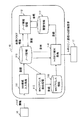
実施形態1におけるシステム構成例として、複数のL2スイッチから構成されるネットワークの物理的な構成情報の取得方法を説明する。図1は、実施形態1に係るネットワークシステムの構成例を示す。
<System configuration>
As an example of a system configuration in the first embodiment, a method for acquiring physical configuration information of a network including a plurality of L2 switches will be described. FIG. 1 shows a configuration example of a network system according to the first embodiment.
図1において、ネットワークシステムは、複数のL2スイッチ(以下単に「スイッチ」と表記)A〜Hを含む。ネットワークは、ループを含まず、或るスイッチ(図1ではスイッチA)を頂点ノードとするツリー構造(木構造)を有している。なお、スイッチの数は例示であり、適宜の数が選択される。 In FIG. 1, the network system includes a plurality of L2 switches (hereinafter simply referred to as “switches”) A to H. The network does not include a loop and has a tree structure (tree structure) in which a certain switch (switch A in FIG. 1) is a vertex node. Note that the number of switches is an example, and an appropriate number is selected.
また、図1において、各スイッチA〜Hを示すブロック中の括弧書きで示されたラテン文字(アルファベット)は、当該スイッチが有するMACアドレスを示す。また、ブロック中の下段に示された数値は、当該スイッチのIP(Internet Protocol)アドレスを示
す。例えば、スイッチAは、MACアドレス“A”と、IPアドレス“192.168.100.10”とを有する。
In FIG. 1, the Latin characters (alphabetic characters) shown in parentheses in the blocks indicating the switches A to H indicate the MAC addresses of the switches. The numerical value shown in the lower part of the block indicates the IP (Internet Protocol) address of the switch. For example, the switch A has a MAC address “A” and an IP address “192.168.100.10”.
ネットワークシステムは、スイッチA〜Hを含むネットワークの管理用端末(以下、単に「端末」と表記)10を含んでいる。端末10が生成装置に相当する。端末10はスイッチによって形成されるネットワークとは異なるネットワーク(アウトバンド)に属する。 The network system includes a network management terminal (hereinafter simply referred to as “terminal”) 10 including switches A to H. The terminal 10 corresponds to a generation device. The terminal 10 belongs to a network (outband) different from the network formed by the switches.
端末10は、SNMPマネージャとして機能し、各スイッチA〜HはSNMPエージェントとして機能する。端末10は、SNMPに基づくメッセージ交換によって、各スイッチA〜HからsysUpTime(稼働時間)情報および学習テーブル情報(MAC学習テーブル
に登録されたMACアドレス)を取得することができる。端末10は、sysUpTime情報お
よび学習テーブル情報の解析によって、ネットワークの構成をツリー構造として取得することができる。
The terminal 10 functions as an SNMP manager, and the switches A to H function as SNMP agents. The terminal 10 can obtain sysUpTime (operation time) information and learning table information (MAC address registered in the MAC learning table) from each of the switches A to H by message exchange based on SNMP. The terminal 10 can acquire the network configuration as a tree structure by analyzing the sysUpTime information and the learning table information.
<端末の構成例>
次に、端末10(ネットワーク構成情報の生成装置)の構成例について説明する。
<<ハードウェア構成>>
図2は、端末10のハードウェア構成例を示す図である。端末10には、例えば、パーソナルコンピュータ(PC),ワークステーション(WS),サーバマシンのような、専用又は汎用の情報処理装置(コンピュータ)を適用することができる。従って、端末10のハードウェア構成として、情報処理装置が備えるハードウェアアーキテクチャを適用することができる。端末10は、「情報処理装置」の一例である。
<Example of terminal configuration>
Next, a configuration example of the terminal 10 (network configuration information generation device) will be described.
<< Hardware configuration >>
FIG. 2 is a diagram illustrating a hardware configuration example of the terminal 10. For example, a dedicated or general-purpose information processing device (computer) such as a personal computer (PC), a workstation (WS), or a server machine can be applied to the terminal 10. Therefore, the hardware architecture of the information processing apparatus can be applied as the hardware configuration of the terminal 10. The terminal 10 is an example of an “information processing device”.
図2において、端末10は、例として、CPU11と、主記憶装置12と、補助記憶装置13と、通信インタフェース回路(通信I/F)14と、I/O(Input/Output)デバイス15とを備える。CPU11,主記憶装置12,補助記憶装置13,通信I/F14及びI/Oデバイス15は、バスBを介して相互に接続されている。
In FIG. 2, the terminal 10 includes, as an example, a
主記憶装置12は、CPU11の作業領域として使用されるメインメモリとして機能する。メインメモリは、例えば、RAM(Random Access Memory)及びROM(Read Only Memory)によって形成される。補助記憶装置13は、CPU11によって実行される各種のプログラム,及び各プログラムの実行時に使用されるデータを記憶する。
The
補助記憶装置13は、例えば、不揮発性記録媒体であり、例えば、ハードディスク,フラッシュメモリ,EEPROM(Electrically Erasable Programmable Read-Only Memory)の少なくとも1つを用いて形成することができる。主記憶装置12及び補助記憶装置
13のそれぞれは、記録媒体の一例である。
The
通信I/F14は、通信を司る回路又は装置であり、例えば、既存のネットワーク・カードやネットワーク・インタフェース・カード(NIC)と呼ばれるLAN(Local Area
Network)用のインタフェース装置を適用することができる。通信I/F14に、通信回線を介して複数のスイッチA〜Hが接続される。端末10と各スイッチとの通信は通信I/F14を介して行われる。通信I/F14は、通信装置の一例である。
The communication I /
Network) interface devices can be applied. A plurality of switches A to H are connected to the communication I /
I/Oデバイス15は、周辺装置のインタフェース処理を司る回路又は装置である。I/Oデバイス15には、周辺装置として、例えば、入力装置16と、出力装置17とが接続される。入力装置16は、例えば、キーボード,ボタン,ポインティングデバイス,タッチパネルである。出力装置17は、例えば、ディスプレイ装置やプリンタである。入力装置16及び出力装置17(ディスプレイ装置)は、管理者及び作業者(オペレータ)が情報を入力、或いは情報を取得するためのユーザインタフェース(UI)を提供する。
The I /
CPU11は、補助記憶装置13にインストールされたプログラムを主記憶装置12にロードして実行することにより、端末10としての機能を発揮することができる。CPU11は、プロセッサ(マイクロプロセッサ)や制御装置の一例である。CPU11の代わりに、DSPを使用することもできる。
The
また、図2の例では、端末10に周辺装置として接続された入力装置16及び出力装置
17がUIを提供する例について説明した。但し、端末10は、通信I/F14に接続された通信回線を介して接続された他の情報処理装置に対し、端末10の操作用のUIを提供する構成を適用することもできる。例えば、CPU11によるプログラム実行によって、端末10がWebサーバとして機能することができる。
In the example of FIG. 2, the example in which the
この場合、Webサーバとしての端末10は、Webクライアントとしての他の情報処理装置との通信(例えばHTTP(HyperText Transfer Protocol)通信)により、We
bベースの端末10の操作用のWebページ(UI)を提供することができる。そして、CPU11は、他の情報処理装置においてWebページの利用により入力された情報に従って、ネットワーク構成情報の更新処理を実施することができる。
In this case, the terminal 10 serving as the Web server communicates with another information processing apparatus serving as the Web client (for example, HTTP (HyperText Transfer Protocol) communication).
A web page (UI) for operating the b-based
図3は、端末10においてCPU11がプログラムを実行することによって実現される端末10の機能を示すブロック図である。図3に示すように、端末10は、CPU11のプログラム実行によって、ネットワーク構成入力処理111と、ノード情報処理112と、MACアドレス抽出処理113と、トポロジ解析処理114とを実行する。
FIG. 3 is a block diagram showing functions of the terminal 10 realized by the
また、主記憶装置12及び補助記憶装置13の少なくとも一方は、ノード情報データベース115(ノード情報DB115)と、MACアドレス情報データベース116(MACアドレス情報DB116)と、階層情報データベース117(階層情報DB117)とを記憶する。
At least one of the
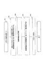
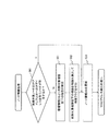
図4は、端末10における全体の処理例を示すフローチャートである。図4に示すように、ネットワーク構成入力処理111では、UI(例えば入力装置16)から入力されるノード情報を、ノード情報DB115に登録する処理が行われる(01)。ノード情報は、機器(例えば、スイッチ)の情報である。以下、ネットワーク機器及びネットワーク装置をまとめて、「機器」又は「ノード」と表記する。
FIG. 4 is a flowchart illustrating an example of overall processing in the terminal 10. As shown in FIG. 4, in the network
次に、ノード情報処理112において、ネットワーク上に存在する機器を特定する処理が行われる(02)。このとき、ノード情報DB115からの削除フラグ情報の取得、及び削除フラグに基づくノード情報DB115の更新処理が実行される。更新処理にあたり、必要に応じて階層情報DB117が参照される(詳細は後述)。
Next, in the
次に、MACアドレス抽出処理113として、特定された機器のsysUpTimeを用いた機
器のMACアドレスの更新処理と、MACアドレスの取得が実施される(03)。このとき、取得されたMACアドレスをMACアドレス情報DB116に登録する処理が行われる(詳細は後述)。
Next, as MAC
次に、トポロジ解析処理114が実行される(04)。トポロジ解析処理114では、MACアドレス情報を元に、ネットワーク構成情報を取得して保存する処理が行われる。すなわち、MACアドレス情報を用いてノード情報DB115が参照され、トポロジ情報が生成され、階層情報DB117に登録される。また、トポロジ解析処理114によって、ネットワークのトポロジや、通信NGの表示がUI(例えば、出力装置17に含まれるディスプレイ装置)に表示される。トポロジ解析処理114の詳細は後述する。
Next,
<DB構成>
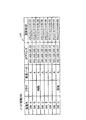
図5は、ノード情報DB115のデータ構造例を示す図であり、図6は、MACアドレス情報DB116のデータ構造例を示す図であり、図7は、階層情報DB117のデータ構造例を示す図である。
<DB configuration>
5 is a diagram showing an example of the data structure of the
図5に示すように、ノード情報DB115には、ネットワークを形成する機器(図1の
例ではスイッチ)の識別子(例えば、装置名)毎に用意された複数のエントリが登録されるテーブルが記憶される。各エントリには、装置名に対応する「フラグ」,「頂点ノード」,「IPアドレス」,及び「更新時刻」が記憶される。
As shown in FIG. 5, the
「フラグ」は、機器がネットワークから削除されたことを示す「削除フラグ」を設定するために使用される。「頂点ノード」は、ネットワークを形成するツリーにおける頂点ノードとなる機器の識別子を示す。「IPアドレス」は、当該機器のIPアドレスを示す。「更新時刻」は、当該エントリの更新時刻を示す。 The “flag” is used to set a “deletion flag” indicating that the device has been deleted from the network. “Vertex node” indicates an identifier of a device that is a vertex node in a tree forming the network. “IP address” indicates the IP address of the device. “Update time” indicates the update time of the entry.
図6に示すように、MACアドレス情報DB116には、複数のエントリが登録されるテーブルが記憶される。各エントリには、装置名に対応する、「下位ポート」,「自MACアドレス」,「対向装置1」,「対向装置2」,「対向装置3」,及び「更新日時」が記憶される。対向装置の情報として、ツリーの深さに応じた数の対向装置の識別子(装置名)が記憶される。
As shown in FIG. 6, the MAC
エントリは、各機器が有する下位ポート(下位ノードを収容するポート)毎に用意される。例えば、スイッチA(図1)に着目すると、スイッチAは、スイッチBを収容するポート(下位ポート)2と、スイッチCを収容するポート(下位ポート)3とを有している。このため、図5に示すように、MACアドレス情報DB116には、スイッチAのポート2に係るエントリと、スイッチAのポート3に係るエントリとが登録される。
An entry is prepared for each lower port (port accommodating a lower node) of each device. For example, paying attention to the switch A (FIG. 1), the switch A has a port (lower port) 2 that accommodates the switch B and a port (lower port) 3 that accommodates the switch C. Therefore, as shown in FIG. 5, an entry related to
スイッチAのポート2に係るエントリに着目すると、「下位ポート」として、ポート2の識別子(ポート番号)が登録される。また、「自MACアドレス」として、スイッチAのMACアドレスが登録される。また、「対向装置1」として、ポート2に接続された下位ノードに相当するスイッチBの識別子が登録される。さらに、「対向装置2」,及び「対向装置3」として、スイッチBが収容する下位ノード(図1の例では、スイッチD及びスイッチE)の識別子が登録される。「更新日時」として、エントリの更新日時が登録される。
Focusing on the entry related to
図7に示すように、階層情報DB117には、各機器の直下に位置する下位ノードに係る1以上のエントリが登録されるテーブルが記憶される。各エントリには、機器の識別子(装置名)に対応する、「頂点ノード」,「階層番号」,「リンク情報」,「使用ポート」及び「更新日時」が登録(記憶)される。各機器の直下に位置する下位ノードについてのエントリが有するポート毎に用意される。
As illustrated in FIG. 7, the
例えば、スイッチAに関しては、スイッチAの直下に位置する下位ノードであるスイッチB及びスイッチCに対応するエントリが登録される。スイッチAのスイッチB(下位ポート2)に係るエントリでは、「頂点ノード」として、スイッチAの識別子が登録される。また、「階層番号」として、ツリーの頂点が属する階層(深さ)を示す階層番号“0”が登録される。また、「リンク情報1」として、スイッチAの直下にリンクを介して接続された他の機器であるスイッチBの識別子(装置名)が登録される。また、「使用ポート」として、スイッチAがスイッチBとの接続に使用するポート2の識別子(ポート番号)が登録される。そして、「更新日時」として、エントリの更新日時が登録される。
For example, for switch A, entries corresponding to switch B and switch C, which are lower nodes located immediately below switch A, are registered. In the entry related to the switch B (lower port 2) of the switch A, the identifier of the switch A is registered as “vertex node”. In addition, a hierarchy number “0” indicating the hierarchy (depth) to which the vertex of the tree belongs is registered as the “hierarchy number”. In addition, as “link
また、スイッチBに関しては、下位ノードであるスイッチD及びスイッチEに対応するエントリが登録される。例えば、スイッチBのスイッチD(ポート2)に係るエントリでは、「頂点ノード」として、スイッチAの識別子が登録される。また、「階層番号」として、頂点ノードの次の階層(深さ)を示す階層番号“1”が登録される。また、「リンク情報1」として、スイッチBの直下にリンクを介して接続された他の機器であるスイッチDの識別子が登録される。また、「使用ポート」として、スイッチBがスイッチDとの接
続に使用するポート2の識別子(ポート番号)が登録される。そして、「更新日時」として、エントリの更新日時が登録される。このようにして、各機器が有する下位ノードに係るエントリが階層情報DB117に登録される。なお、ネットワークにおける最下位層(階層番号“2”)に位置するエッジノード、すなわち、各スイッチE〜Gについては、下位ノードに係る情報である「リンク情報1」及び「使用ポート」は登録されない。
As for the switch B, entries corresponding to the switches D and E which are lower nodes are registered. For example, in the entry related to the switch D (port 2) of the switch B, the identifier of the switch A is registered as “vertex node”. Also, a hierarchy number “1” indicating the next hierarchy (depth) of the vertex node is registered as the “hierarchy number”. Further, as “link
上記した図6及び図7に係る説明では、対向装置の情報及びリンク情報として、機器(スイッチ)の識別子として装置名が登録される例を示した。但し、装置名に加えて、各機器のMACアドレスが記憶される構成を採用しても良い。また、“装置名”として、各機器のMACアドレスを用いる構成も採用可能である。 In the description according to FIGS. 6 and 7 described above, an example is shown in which the device name is registered as the identifier of the device (switch) as the information of the opposite device and the link information. However, a configuration may be adopted in which the MAC address of each device is stored in addition to the device name. Further, a configuration using the MAC address of each device as the “device name” can also be adopted.
<端末の動作>
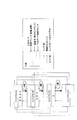
以下、端末10における動作例(処理例)について説明する。図8は、動作例の説明図である。図8に示すように、図1に示したネットワーク(スイッチA〜H)に関して、中間ノードであるスイッチCが削除される一方で、エッジノードとしてスイッチHが追加された場合における動作について説明する。
<Terminal operation>
Hereinafter, an operation example (processing example) in the terminal 10 will be described. FIG. 8 is an explanatory diagram of an operation example. As shown in FIG. 8, the operation when the switch C as an intermediate node is deleted while the switch H is added as an edge node in the network (switches A to H) shown in FIG. 1 will be described.
<<ネットワーク構成入力処理>>
図9は、ネットワーク構成入力処理111(図4の01)の例を示すフローチャートである。図9に示す処理は、UI(例えば入力装置16)を用いた管理者からの機器情報(ノード情報)の入力を契機に開始される。
<< Network configuration input processing >>
FIG. 9 is a flowchart showing an example of the network configuration input process 111 (01 in FIG. 4). The process shown in FIG. 9 is triggered by the input of device information (node information) from an administrator using a UI (for example, the input device 16).
例えば、ノード情報として、図8に示した様に、ノード情報DB115に、スイッチCの削除を示すノード情報と、スイッチHの追加を示すノード情報とが入力された場合を想定する。
For example, assume that node information indicating deletion of the switch C and node information indicating addition of the switch H are input to the
すると、CPU11は、入力されたノード情報(入力情報)をノード情報DB115に反映する処理を行う(011)。具体的には、図4に示すように、CPU11は、スイッチHに対応するエントリを追加登録する。次に、CPU11は、追加又は削除フラグの設定を行う(012)。すなわち、CPU11は、スイッチHのエントリに追加フラグを設定する。また、CPU11は、既存のスイッチCのエントリに、削除フラグを設定する。そして、CPU11は、スイッチC及びスイッチHの更新時刻の更新処理を行う(013)。013の処理が終了すると、CPU11は、ノード情報処理112に移行する。
Then, the
<<ノード情報処理>>
図10は、ノード情報処理112(図4の02)の例を示すフローチャートである。図10に示す処理は、例えば、CPU11によって、図9に示したネットワーク構成入力処理111に引き続いて実行される。
<< Node information processing >>
FIG. 10 is a flowchart illustrating an example of the node information processing 112 (02 in FIG. 4). The process illustrated in FIG. 10 is executed, for example, by the
図10において、CPU11は、階層情報DB117から削除対象機器の配下の機器を検索する(021)。次に、CPU11は、削除対象機器の配下の機器を削除対象に決定し、ノード情報DB115に削除フラグを付加する(022)。
In FIG. 10, the
次に、CPU11は、階層情報DB117において、“装置名”及び“リンク情報”として、削除対象機器の識別子が登録された行(エントリ)を削除する。そして、CPU11は、ノード情報DB115を更新する(023)。すなわち、CPU11は、削除フラグが設定されたエントリを削除する。
Next, the
このように、ノード情報処理112では、前回更新時のデータが格納されている階層情報DB117とノード情報DB115とを比較し、削除対象となった機器の配下に機器が
存在しないかを確認する。配下の機器が存在した場合、CPU11は、その配下の機器も削除対象とし、ノード情報DB115及び階層情報DB117を更新する。ノード情報処理112の終了後、MACアドレス抽出処理113に移行する。
As described above, the
上記010の処理時における階層情報DB117が図7に示した登録内容を有し、削除対象機器がスイッチCである場合の動作の詳細について、図11を用いて説明する。図11に示すように、CPU11は、階層情報DB117におけるスイッチCのエントリを参照し、スイッチCの配下の機器であるスイッチF及びスイッチGを検出する(図11<1>)。検出結果に従い、CPU11は、スイッチF及びスイッチGを削除対象として決定する。
Details of the operation in the case where the
次に、CPU11は、スイッチF及びスイッチGのエントリを参照し、スイッチF及びスイッチGの配下の機器を探索する。但し、スイッチF及びスイッチGのそれぞれは配下の機器を有しないので、探索が終了する。階層情報DB117の参照によって、最終的な削除対象の機器として、スイッチC,スイッチF及びスイッチGが決定される。
Next, the
CPU11は、装置名として、“スイッチC”,“スイッチF”,“スイッチG”が登録されたエントリを階層情報DB117から削除する。さらに、CPU11は、“スイッチC”,“スイッチF”,“スイッチG”のいずれかがリンク情報として登録されたエントリも削除する。図7に示す例では、リンク情報“スイッチC”を含む装置名“スイッチA”のエントリ(上から2番目)が削除される(図11<3>)。
The
そして、CPU11は、ノード情報DB115にアクセスし、装置名がスイッチC,スイッチF及びスイッチGのいずれかであるエントリを削除する。これによって、ノード情報DB115の登録内容が、図12に示す状態となる。
Then, the
<<MACアドレス抽出処理>>
MACアドレス抽出処理113では、各機器のMACアドレスの部分的な(下位ポートに係る)最新化を目的として、MACアドレスの取得を実施する。MACアドレス抽出処理113では、予め設定されたsysUpTimeの閾値が用いられる。或る機器がネットワーク
追加されて間もない場合、或いは、或る機器で再起動が実施された場合には、これらの機器におけるsysUpTimeは閾値を下回ると考えられる。そこで、閾値よりもsysUpTimeが小さい機器(以下、「対象機器」と表記することもある)が存在していた場合には、対象機器が追加された機器か、再起動が実施された機器かが判定される。対象機器が追加された機器であれば、対象機器を含む部分木の頂点ノードから対象機器(追加ノード)へのping送信が行われる。これに対し、対象機器が再起動された機器(再起動ノード)であれば、対象機器の配下の機器(下位ノード)からのping送信が実施される。
<< MAC address extraction process >>
In the MAC
pingの送信によって、対象機器が含まれる部分木を形成する各機器において、学習テーブルの部分的な最新化、すなわち、各機器の下位ポートに係るMACアドレスの強制的な学習が実施される。sysUpTimeの閾値は、ネットワークの規模により通信の頻度が異なる
と考え、管理者によって適宜設定される。また、pingの送信に関しては、頂点ノードがノード情報DB115に登録されたping送信対象装置のIPアドレスを端末10から得て実施する。また、再起動の機器に係るping送信に際しては、端末10が有する階層情報DB117に登録された階層情報が使用される。
By transmitting the ping, in each device forming a subtree including the target device, partial update of the learning table, that is, forced learning of the MAC address related to the lower port of each device is performed. The sysUpTime threshold is set as appropriate by the administrator, assuming that the frequency of communication varies depending on the size of the network. Further, regarding the ping transmission, the vertex node obtains the IP address of the ping transmission target device registered in the
図13は、MACアドレス抽出処理113(図4の03)の例を示すフローチャートである。図13の処理は、CPU11がノード情報処理112に引き続いて実行する。CPU11は、ノード情報DB115の登録内容(図12参照)を元に、MACアドレス情報DB116を更新する(031)。031の開始時点で、MACアドレス情報DB116
には、図6に示した内容が登録されている。
FIG. 13 is a flowchart showing an example of the MAC address extraction process 113 (03 in FIG. 4). The
In FIG. 6, the contents shown in FIG. 6 are registered.
具体的には、CPU11は、ノード情報DB115から削除された スイッチC、スイ
ッチF、スイッチGを、ノード情報DB115とMACアドレス情報DB116との差分により特定する。そして、CPU11は、MACアドレス情報DB116から、スイッチC,スイッチF及びスイッチGのいずれかが“装置名”又は“対向装置”として登録された行(エントリ)を削除する。この結果、図6に示したMACアドレス情報DB116から、装置名“スイッチC”のエントリと、対向装置“スイッチC”,“スイッチF”及び“スイッチG”が登録された装置名“スイッチA”のエントリとが削除される。
Specifically, the
次に、CPU11は、ノード情報DB115に登録された残りのスイッチA,スイッチB,スイッチD,スイッチE及びスイッチHに関して、sysUpTime(稼働時間)の取得処
理が終了しているか否かを判定する(032)。このとき、全てのスイッチに対するsysUpTime(稼働時間)の取得処理が終了している場合(032,Y)には、MACアドレス
抽出処理113が終了し、トポロジ解析処理114へ移行する。これに対し、残りのスイッチがある場合(032,N)には、CPU11は、残りのスイッチの1つを選択し、処理を033に進める。スイッチの選択は、例えば、エントリの登録順で行われる。
Next, the
033では、CPU11は、通信I/F14を用いて、032で選択したスイッチ(選択スイッチ)へSNMPのGet Requestメッセージを送信し、当該スイッチのsysUpTime(稼働時間)を取得する(033)。このとき、Get Requestメッセージの宛先IPアドレ
スには、ノード情報DB115に記憶された、選択スイッチのIPアドレスを用いる。
In 033, the
CPU11は、Get Requestメッセージによって、選択スイッチから送信されたsysUpTime(稼働時間)を含む応答メッセージを通信I/F14を介して受信する。CPU11は、ノード情報DB115と、応答メッセージの送信元IPアドレスとを参照して、応答メッセージを送信したスイッチを特定する。続いて、CPU11は、稼働時間を取得した選択スイッチに関して、稼働時間の値が、端末10上で予め設定された稼働時間の閾値(主記憶装置12及び補助記憶装置13との少なくとも一方に予め記憶されている)より小さいか否かを判定する(034)。このとき、稼働時間の値が閾値以上の場合(034,N)には、処理が032に戻る。
In response to the Get Request message, the
これに対し、稼働時間が閾値より小さいと判定された場合(034,Y)には、CPU11は、選択スイッチが上述した対象機器であると判定して、処理を035に進める。035では、CPU11は、ノード情報DB115を参照し、選択スイッチのエントリに追加フラグが設定されているか否かを判定する。このとき、追加フラグが設定されている場合(035,Y)には、CPU11は、選択スイッチ(すなわち対象機器)が追加された機器であると判定し、処理を036に進める。一方、追加フラグが設定されていない場合(035,N)には、選択スイッチ(すなわち対象機器)が再起動を実施した機器であると判定し、処理を037に進める。
On the other hand, when it is determined that the operation time is smaller than the threshold (034, Y), the
036では、CPU11は、対象機器(追加された機器)を含む部分木の頂点ノード(スイッチA)に対し、対象機器へ向けてpingを送信することを指示する(034)。例えば、対象機器がスイッチHである場合には、CPU11は、pingの送信指示に、スイッチHのIPアドレス(ノード情報DB115に記憶されている)を含める。pingの送信指示の宛先アドレスには、スイッチAのIPアドレスが設定される。
In 036, the
送信指示を受け取った頂点ノード(スイッチA)は、スイッチHに対するARP(Address Resolution Protocol)を実行する。ARPメッセージがブロードキャストによって
下位スイッチへ向け転送され、結果として1つのARPメッセージがスイッチB及びスイ
ッチEを介してスイッチHに到達する。スイッチHはスイッチAからのARPメッセージに応答し、スイッチAはスイッチHのMACアドレスを学習する。スイッチHのMACアドレスは、スイッチHのIPアドレスと関連付けてスイッチAのARPテーブルに登録される。スイッチAからスイッチHへの通信は、ARPテーブルに登録されたMACアドレスを用いて行われる。
The vertex node (switch A) that has received the transmission instruction executes ARP (Address Resolution Protocol) for the switch H. The ARP message is forwarded to the lower switch by broadcasting, and as a result, one ARP message reaches the switch H via the switch B and the switch E. Switch H responds to the ARP message from switch A, and switch A learns the MAC address of switch H. The MAC address of switch H is registered in the ARP table of switch A in association with the IP address of switch H. Communication from the switch A to the switch H is performed using the MAC address registered in the ARP table.
スイッチHは、pingメッセージに対する応答メッセージ(echo-reply)をスイッチA宛てに送信する。応答メッセージは、pingメッセージの経路を逆方向に辿って(スイッチE→スイッチB)、最終的にスイッチAに到達する。このとき、スイッチEでは、応答メッセージを受信したときに、応答メッセージの受信ポートの識別子(ポート番号)と、応答メッセージに含まれた送信元MACアドレスから、スイッチEのポート2にスイッチHが接続されていることを学習する(MAC学習テーブルに登録する)ことができる。
The switch H transmits a response message (echo-reply) to the ping message to the switch A. The response message traces the path of the ping message in the reverse direction (switch E → switch B), and finally reaches the switch A. At this time, when the switch E receives the response message, the switch H is connected to the
同様に、スイッチBは、応答メッセージをポート3で受信することによって、スイッチHがポート3の配下に存在することを学習する(MAC学習テーブルに登録する)ことができる。さらに、スイッチAは、ポート2から応答メッセージを受信することで、ポート2の配下に位置するスイッチHの存在を学習する(MAC学習テーブルに登録する)ことができる。
Similarly, the switch B can learn (register in the MAC learning table) that the switch H exists under the
このように、エッジノード(スイッチH)から頂点ノード(スイッチA)への応答メッセージの送信によって、スイッチE,スイッチB及びスイッチAのそれぞれにおいて、下流から上流方向へのMACアドレス学習が実行される。これによって、部分木を形成する各ノード(スイッチA−スイッチB−スイッチE−スイッチH)において、部分的な(下位ポートに関する)MAC学習内容の最新化がなされる。換言すれば、部分木を形成するスイッチA,B,E及びHにおける下位ポートに関して学習されたMACアドレスの登録内容が実際の部分木ネットワークの構成と一致した状態となる。その後、CPU11は、処理を032に戻す。
As described above, the MAC address learning from the downstream to the upstream is performed in each of the switch E, the switch B, and the switch A by transmitting the response message from the edge node (switch H) to the vertex node (switch A). . As a result, the MAC learning contents are partially updated (related to the lower ports) at each node (switch A-switch B-switch E-switch H) forming the subtree. In other words, the registered contents of the MAC address learned for the lower ports in the switches A, B, E, and H forming the subtree are in a state that matches the actual configuration of the subtree network. Thereafter, the
037及び038は、対象機器が再起動を実施した機器と考えられる場合に行われる処理である。例えば、図8に示すスイッチBが再起動を実施した機器である場合を例として説明する。037では、CPU11は、階層情報DB117(図7)における、スイッチBを含む構成情報を得る。構成情報は、対象機器(スイッチB)の配下の機器の情報である。配下の機器は、対象機器の直下にある機器だけでなく、直下にある機器の配下の機器も含む。
037 and 038 are processes performed when the target device is considered to be a device that has been restarted. For example, a case where the switch B illustrated in FIG. 8 is a device that has been restarted will be described as an example. In 037, the
具体的には、CPU11は、階層情報DB117の装置名“スイッチB”のエントリを参照し、リンク情報として、スイッチDの識別子(装置名)と、スイッチEの識別子とを得る。続いて、CPU11は、スイッチD及びスイッチEの識別子を元に、階層情報DB117のスイッチD及びスイッチEのエントリを参照する。スイッチD及びEのエントリにはリンク情報が登録されていないので、CPU11は、配下の機器の探索を終了する。このようにして、構成情報として、スイッチBの配下にあるスイッチD及びスイッチEの情報が得られる。このような、対象機器の配下にある機器を、「構成機器」を呼ぶこともある。
Specifically, the
CPU11は、処理を038に進めて、通信I/F14を用いて、対象機器(スイッチB)に対し、スイッチD及びスイッチEへpingを送信することを指示する。スイッチD及びスイッチEへping送信のために、指示には、ノード情報DB115に登録されたスイッチD及びスイッチEのIPアドレスが含められる。
The
スイッチBは、指示に従って、スイッチD及びスイッチEに対してpingを送信する。ス
イッチBは、スイッチDからpingの応答メッセージを受信することで、応答メッセージの受信ポート(ポート2)とスイッチDのMACアドレスとの関連を学習することができる。さらに、スイッチBは、スイッチEからの応答メッセージを受信することで、応答メッセージの受信ポート(ポート3)とスイッチEのMACアドレスとの関連を学習することができる。038の処理が終了すると、処理が032に戻る。なお、上記のようなping送信の処理に代えて、スイッチD及びEに対し、スイッチBへpingを送信することを指示することで、スイッチBが下位ポートに係るMACアドレスを学習するようにしても良い。
The switch B sends a ping to the switch D and the switch E according to the instruction. By receiving the ping response message from the switch D, the switch B can learn the association between the response message reception port (port 2) and the MAC address of the switch D. Further, by receiving the response message from the switch E, the switch B can learn the association between the response message reception port (port 3) and the MAC address of the switch E. When the process of 038 ends, the process returns to 032. Instead of the above ping transmission process, by instructing the switches D and E to transmit a ping to the switch B, the switch B learns the MAC address related to the lower port. Also good.
もし、スイッチDの配下に、階層情報DB117にリンク情報が登録済みの機器(例えばスイッチX:図示せず)がある場合には、当該スイッチXも構成機器に含められ、スイッチBのping送信の指示には、スイッチDの配下のスイッチXに対するping指示も含められる。
If there is a device (eg, switch X: not shown) whose link information is registered in the
このようにして、再起動を実施した対象機器に対し、階層情報DB117に登録された配下の機器の情報に基づくping送信によって、配下の機器のMACアドレスを学習することができる。但し、追加に係る機器(例えばスイッチH)のリンク情報が階層情報DB117に反映されていない場合には、038にて当該追加された機器に対してpingを送信することができない。しかし、追加された機器に関しては、頂点ノード(スイッチA)からスイッチHへのping送信(036)によって、再起動を実施した対象機器(スイッチB)は、追加された機器(スイッチH)からの応答メッセージを受信する。これによって、当該追加された機器のMACアドレスを学習することができる。
In this way, the MAC address of the subordinate device can be learned by ping transmission based on the information of the subordinate device registered in the
032にて、ノード情報DB115に登録された全ての機器(図12の例では、スイッチA,スイッチB,スイッチD,スイッチE及びスイッチH)に対するsysUpTime取得に
係る処理(033〜038)が終了すると(032,Y)、処理が039に進む。
At 032, when the processing (033 to 038) relating to the acquisition of sysUpTime for all devices registered in the node information DB 115 (in the example of FIG. 12, switch A, switch B, switch D, switch E, and switch H) is completed. (032, Y), the process proceeds to 039.
039では、CPU11は、SNMPを用いて、MACアドレス情報DB116の更新処理を行う。すなわち、CPU11は、ノード情報DB115に登録された全ての機器(スイッチ)を対象として、MAC学習テーブル中の下位ポートに係るMACアドレスの登録内容を問い合わせる。問い合わせにおいては、各スイッチのIPアドレスが、スイッチの識別子として使用される。すなわち、問い合わせメッセージの宛先IPアドレスに、問い合わせ対象のスイッチのIPアドレスが設定される。
In 039, the
CPU11は、問い合わせの回答を各機器(スイッチ)から受け取る。回答メッセージの送信元IPアドレスから、回答を行ったスイッチを識別することができる。CPU11は、回答内容とMACアドレス情報DB116の内容との差分がある場合には、更新作業を行う。回答は、問い合わせ対象の機器(スイッチ)のMACアドレスと、1以上の下位ポートの識別子(ポート番号)とこれに対応するMACアドレスとの関連を示す情報を含む。
The
例えば、CPU11は、スイッチEに対する問い合わせにおいて、スイッチEから、スイッチEのMACアドレスと、スイッチEのポート2の識別子(ポート番号)と、ポート2に接続されたスイッチHのMACアドレスとを含む回答を受信する。CPU11は、受信された回答に基づいて、MACアドレス情報DB116の更新を行う。
For example, in the inquiry to the switch E, the
図14は、036の処理によるMACアドレス情報DB116の更新の結果を示す。図6に示したMACアドレス情報DB116の登録内容から、次のような更新がなされている。すなわち、023(図10)の処理によって、スイッチCに係るエントリが削除されている。また、スイッチA及びスイッチBからの回答に基づき、CPU11によって、スイッチA及びスイッチBのそれぞれのエントリに、“対向装置4”,“対向装置2”とし
て、スイッチHの識別子が追加される。さらに、スイッチEからの回答に基づき、CPU11によって、MACアドレス情報DB116にスイッチEのエントリが追加されている。スイッチEのエントリには、自MACアドレスとしてスイッチEのMACアドレスが登録され、下位ポートとしてポート2が登録され、対向装置1として、スイッチHの識別子(装置名)が登録される。
FIG. 14 shows the result of updating the MAC
なお、上記の説明では、各スイッチからの回答に含まれた下位ポートのMACアドレス(例えば、スイッチHのMACアドレス)は、階層情報DB117に登録されない。但し、下位ポートのMACアドレスが、別途管理される構成を採用しても良い。036の処理が終了すると、MACアドレス抽出処理113が終了し、トポロジ解析処理114に進む。
In the above description, the MAC address of the lower port included in the response from each switch (for example, the MAC address of the switch H) is not registered in the
<<トポロジ解析処理>>
トポロジ解析処理114では、MACアドレス情報DB116が参照され、ツリー構造が取得される。トポロジの解析は、新規に追加された機器(追加フラグを持つ機器)を対象として、当該対象機器のMACアドレスを下位ポートに有する部分木のみのネットワーク構成情報の取得が実施され、階層情報DB117が更新される。
<< Topology analysis processing >>
In the
図15は、トポロジ解析処理114(図4の04)の例を示すフローチャートである。CPU11は、ノード情報DB115(図12)を参照して、追加フラグが設定されているエントリを確認する。このとき、スイッチHが新規追加の機器として特定される。CPU11は、スイッチHを対象として、接続関係抽出法に従って、接続関係を抽出する(041)。
FIG. 15 is a flowchart showing an example of the topology analysis process 114 (04 in FIG. 4). The
図16A〜図16Dは、図15の041にて実行される接続関係抽出法の説明図である。図16A〜図16Dは、例として、スイッチA,スイッチB,スイッチE及びスイッチHによって形成される部分木に係る接続関係抽出法が例示されている。 16A to 16D are explanatory diagrams of the connection relation extraction method executed in 041 of FIG. 16A to 16D illustrate, as an example, a connection relation extraction method related to a subtree formed by the switch A, the switch B, the switch E, and the switch H.
ここに、スイッチAのMAC学習テーブルには、下位ポートに接続されたノードのMACアドレス(下位ポートに係るMACアドレス)として、スイッチB,スイッチD,スイッチE及びスイッチHのそれぞれのMACアドレス(B,D,E,H)が登録されている。また、スイッチBのMAC学習テーブルには、下位ポートに係るMACアドレスとして、スイッチD,スイッチE及びスイッチHのそれぞれのMACアドレス(D,E,H)が登録されている。さらに、スイッチEのMAC学習テーブルには、下位ポートに係るMACアドレスとして、スイッチHのMACアドレス(H)が登録されている。スイッチHは配下のノード(下位ノード)を持たないため、MACアドレス学習テーブルには、下位ポートに係るMACアドレスは登録されていない。 Here, in the MAC learning table of the switch A, the MAC addresses (B of the switch B, the switch D, the switch E, and the switch H are shown as the MAC addresses of the nodes connected to the lower ports (MAC addresses related to the lower ports). , D, E, H) are registered. In the MAC learning table of the switch B, the MAC addresses (D, E, H) of the switches D, E, and H are registered as MAC addresses related to the lower ports. Further, in the MAC learning table of the switch E, the MAC address (H) of the switch H is registered as the MAC address related to the lower port. Since the switch H has no subordinate node (lower node), the MAC address related to the lower port is not registered in the MAC address learning table.
(手順1−1)
図16Aに示すように、最初に、共通なMACアドレスを有する装置が双方向に結ばれる。図16Aに示す例では、スイッチA,スイッチB,スイッチE及びスイッチHは、それぞれスイッチHのMACアドレス(H)を有している。このため、するので、スイッチA,スイッチB,スイッチE及びスイッチHは、仮のリンクで双方向に結ばれる。
(Procedure 1-1)
As shown in FIG. 16A, first, devices having a common MAC address are connected bidirectionally. In the example shown in FIG. 16A, the switch A, the switch B, the switch E, and the switch H each have the MAC address (H) of the switch H. For this reason, the switch A, the switch B, the switch E, and the switch H are bi-directionally connected by a temporary link.
(手順1−2)
次に、図16Bに示すように、結ばれた二つの装置のうち、下位ポートに係るMACアドレスの登録数が多い装置が上位装置として決定される。すなわち、スイッチAとスイッチBとの比較では、スイッチAのMACアドレスの登録数(4つ)がスイッチBのMACドレス登録数(2つ)より多いので、スイッチAはスイッチBの上位装置として決定される。また、スイッチBとスイッチEとの比較では、スイッチBのMACアドレスの登録数
(3つ)がスイッチDのMACアドレスの登録数(1つ)より多いので、スイッチBがスイッチEの上位装置として決定される。さらに、スイッチEとスイッチHとの比較では、スイッチEのMACアドレスの登録数(1つ)がスイッチHのMACアドレスの登録数(零)より多いので、スイッチEがスイッチHの上位装置として決定される。この結果、スイッチHからスイッチE,スイッチB及びスイッチAへそれぞれ向かう仮のリンクが削除される。また、スイッチEからスイッチB及びスイッチAへそれぞれ向かう仮のリンクが削除される。さらに、スイッチBからスイッチAへ向かう仮のリンクが削除される。
(Procedure 1-2)
Next, as illustrated in FIG. 16B, among the connected devices, a device with a large number of registered MAC addresses related to the lower ports is determined as a higher device. That is, in the comparison between the switch A and the switch B, the number of registered MAC addresses of the switch A (four) is larger than the number of registered MAC addresses of the switch B (two). Is done. In comparison between the switch B and the switch E, the number of registered MAC addresses of the switch B (three) is larger than the number of registered MAC addresses of the switch D (one). It is determined. Further, in the comparison between the switch E and the switch H, the number of registered MAC addresses of the switch E (one) is larger than the number of registered MAC addresses of the switch H (zero). Is done. As a result, the temporary links from the switch H to the switches E, B, and A are deleted. In addition, the temporary links going from the switch E to the switch B and the switch A are deleted. Further, the temporary link from switch B to switch A is deleted.
(手順1−3)
次に、複数の装置からリンクで接続された装置が存在する場合には、上位装置の中で、MACアドレスの登録数が最小の装置が上位装置として決定される。例えば、図16Bに示したように、スイッチHは、スイッチE,スイッチB及びスイッチAと複数の仮のリンクで接続されている。また、スイッチEは、スイッチB及びスイッチAと複数の仮のリンクで接続されている。このため、スイッチEに関して、スイッチAとスイッチBとの間で、MACアドレスの登録数が比較される。このとき、スイッチBのMACアドレスの登録数(3つ)がスイッチAのMACアドレスの登録数(4つ)より少ない(スイッチBのMACアドレスの登録数が最小である)。従って、図16Cに示すように、スイッチAからスイッチEへの仮のリンクが削除され、スイッチAからスイッチBへのリンクが正式なリンクとして決定され、スイッチBからスイッチEへのリンクが正式なリンクとして決定される。また、スイッチHに関して、スイッチA,スイッチB及びスイッチEの間でMACアドレスの登録数が比較される。この結果、スイッチEのMACアドレスの登録が最小であるので、スイッチAからスイッチHへの仮のリンク、及びスイッチBからスイッチHへの仮のリンクが削除され、スイッチEからスイッチHへのリンクが正式なリンクとして決定される。
(Procedure 1-3)
Next, when there are devices connected by a link from a plurality of devices, the device with the smallest number of registered MAC addresses is determined as the host device among the host devices. For example, as illustrated in FIG. 16B, the switch H is connected to the switches E, B, and A through a plurality of temporary links. The switch E is connected to the switches B and A by a plurality of temporary links. For this reason, regarding the switch E, the number of registered MAC addresses is compared between the switch A and the switch B. At this time, the number of registered MAC addresses of switch B (three) is less than the number of registered MAC addresses of switch A (four) (the number of registered MAC addresses of switch B is the smallest). Therefore, as shown in FIG. 16C, the temporary link from the switch A to the switch E is deleted, the link from the switch A to the switch B is determined as a formal link, and the link from the switch B to the switch E is formal. Determined as a link. In addition, regarding the switch H, the number of registered MAC addresses is compared among the switches A, B, and E. As a result, since the registration of the MAC address of the switch E is minimum, the temporary link from the switch A to the switch H and the temporary link from the switch B to the switch H are deleted, and the link from the switch E to the switch H is deleted. Is determined as the official link.
(手順1−4)
手順1−3で決定された正式なリンクの両端の装置は、互いに共通なMACアドレスを保持している。そこで、共通なMACアドレスを有する、上位装置のポートが下位ポートとして決定される。具体的には、図16Dに示すように、スイッチHとスイッチEとは、共通なMACアドレスとして、スイッチHのMACアドレス(H)を有している。このため、スイッチEにおけるスイッチHと関連するポートが、スイッチHに対する下位ポートとして決定される。スイッチEとスイッチBとは、共通なMACアドレスとして、スイッチEのMACアドレス(E)を保持している。このため、スイッチBにおけるスイッチEのMACアドレスに係るポートが、スイッチEに対する下位ポートとして決定される。そして、スイッチAとスイッチBとは共通なMACアドレスとしてスイッチBのMACアドレスを有している。このため、スイッチAにおけるスイッチBのMACアドレスと関連するポートがスイッチBに対する下位ポートとして決定される。
(Procedure 1-4)
The devices at both ends of the formal link determined in the procedure 1-3 hold a common MAC address. Therefore, the port of the upper device having a common MAC address is determined as the lower port. Specifically, as illustrated in FIG. 16D, the switch H and the switch E have the MAC address (H) of the switch H as a common MAC address. For this reason, the port associated with the switch H in the switch E is determined as a lower port for the switch H. The switch E and the switch B hold the MAC address (E) of the switch E as a common MAC address. Therefore, the port related to the MAC address of the switch E in the switch B is determined as a lower port for the switch E. The switch A and the switch B have the MAC address of the switch B as a common MAC address. Therefore, a port related to the MAC address of switch B in switch A is determined as a lower port for switch B.
041では、CPU11は、上述した接続関係抽出法を用いて、追加対象のスイッチHを含む部分木(スイッチA−スイッチB−スイッチE−スイッチH)に係る接続関係を抽出する(すなわち、部分木のトポロジを特定する)。
In 041, the
各装置(スイッチ)のポートのうち、その先に頂点ノードが接続されているポートを上位ポート、その他のポートを下位ポートとする。下位ポートにMACアドレスが登録されていない装置はエッジノードとして特定することができる。 Of the ports of each device (switch), the port to which the vertex node is connected is the upper port, and the other ports are the lower ports. A device whose MAC address is not registered in a lower port can be identified as an edge node.
CPU11は、上記した接続関係抽出法におけるMACアドレス登録数の比較において、MACアドレス情報DB116に記憶された、或るスイッチに係る対向装置の数を利用する。例えば、MACアドレス情報DB116の登録内容が図14に示す情報であれば、スイッチAに関して、スイッチB,スイッチD,スイッチE,及びスイッチHの識別子が
下位ポートの対向装置の情報として登録されており、これらの識別子の数が、MACアドレス登録数として使用される。スイッチB,スイッチE,及びスイッチHに関しても同様である。このような、MACアドレス情報DB116に登録された情報は、「下位ポートに係るMACアドレスの登録数を示す情報」の一例である。
The
接続関係抽出法の利用によって、MACアドレスを利用したスイッチHを含む部分木に係るトポロジが抽出される。次に、CPU11は、接続関係抽出法に従って得られた階層情報で階層情報DB117を更新する(042)。すなわち、CPU11は、新規に追加された機器、すなわちスイッチHに対する階層番号を計算し、階層情報DB117を更新する。このとき、頂点ノード(スイッチA)の階層番号は「0」に設定される。そして、追加の機器(スイッチH)が、或る機器(スイッチE)の下位に接続される場合には、当該或る機器の階層番号に1を付加した値が追加の機器の階層番号として付加される。スイッチH はスイッチEの配下であるため、スイッチEの階層番号2に1を加えた3となる
。図17は、図7に示した登録内容が更新された階層情報DB117を示す。
By using the connection relation extraction method, the topology related to the subtree including the switch H using the MAC address is extracted. Next, the
次に、CPU11は、階層情報DB117の登録内容(階層番号,リンク情報、使用ポート)に基づいて、ネットワーク構成(ツリー構造)を示す画像(ビュー)を生成する(044)。CPU11は、画像をUI,例えば、出力装置17に含まれるディスプレイ装置に表示する。図18は、ディスプレイ装置に表示されるネットワーク構成を示す画像の例を示す。図18に示すように、画像は、ネットワークを形成する複数のノード(スイッチ)のツリーを示す。
Next, the
各ノードにおいて、対向装置とリンクを介して接続されるポート番号が表示される。スイッチAに関して、下位ポートであるポート2で、スイッチBの上位ポート(ポート1)とリンクを介して接続されていることが表示される。スイッチBに関して、スイッチBは、スイッチDの上位ポート(ポート1)とリンクを介して接続される下位ポート(ポート2)と、スイッチEの上位ポート(ポート1)とリンクを介して接続される下位ポート(ポート3)とを有することが表示される。スイッチEに関して、スイッチBは、スイッチHの上位ポート(ポート1)とリンクを介して接続される下位ポート(ポート2)を有することが表示される。エッジノードであるスイッチD及びスイッチHのそれぞれは、上位ポート(ポート1)で上位ノードと接続されることが表示され、下位ポートに係る情報は存在しないため表示されない。
In each node, a port number connected to the opposite device via a link is displayed. Regarding switch A, it is displayed that
<実施形態1の作用効果>
実施形態1によれば、ネットワーク構成の変更に際して、稼働時間が閾値未満の機器(ノード)を含む部分木がネットワーク構成の変更箇所として特定され、当該部分木に係るトポロジ解析によって、当該部分木のネットワーク構成が更新される。これによって、ネットワーク構成情報の更新のための書換を行う範囲を部分木に抑えることができ、更新時間の短縮化を図ることができる。また、稼働時間が閾値未満の機器を対象とするping送信が実施されることで、部分木を形成する各機器(ノード)の下位ポートに係るMACアドレス学習内容を、最新の状態(下位ノードに係るMACアドレス登録内容が、実際の部分木と一致した状態)にすることができる。
<Effect of
According to the first embodiment, when a network configuration is changed, a subtree including devices (nodes) whose operation time is less than the threshold is specified as a network configuration change location, and the subtree is analyzed by topology analysis related to the subtree. The network configuration is updated. As a result, the rewriting range for updating the network configuration information can be limited to a partial tree, and the update time can be shortened. In addition, by performing ping transmission for devices whose operating time is less than the threshold, the MAC address learning contents related to the lower ports of each device (node) forming the subtree are updated to the latest state (lower node). The MAC address registration content can match the actual subtree).
<変形例>
上記した実施形態1におけるping送信は、ネットワークを形成する機器(ノード)のそれぞれが、MACアドレス学習機能を備えるために実施される。ネットワークに対する機器の追加や、或る機器の再起動に伴い、追加された機器や再起動された機器に対するMACアドレスの登録が静的に(例えばマニュアルで)実行される場合には、ping送信は省略される。
<Modification>
The above-described ping transmission in the first embodiment is performed because each device (node) forming the network has a MAC address learning function. When adding a device to the network or restarting a certain device, registration of the MAC address for the added device or the restarted device is executed statically (for example, manually). Omitted.
また、上記した実施形態1では、頂点ノードから追加の対象機器に関するping送信(036)によって、部分木を形成する各ノードの下位ポートに係るMACアドレスの学習内容(登録状態)が、実際の部分木のネットワーク構成と一致した状態にすることができる。さらに、以下のような処理によって、追加の対象機器における上位ポートに係るMACアドレスの学習内容を、部分木の構成と一致させることができる。 Further, in the first embodiment described above, the learning content (registration state) of the MAC address related to the lower port of each node forming the subtree by the ping transmission (036) regarding the additional target device from the vertex node is the actual part. It can be in a state consistent with the network configuration of the tree. Furthermore, the learning contents of the MAC address related to the upper port in the additional target device can be matched with the configuration of the subtree by the following processing.
図19は、上位ポートに係るMACアドレスの強制的な学習の制御方法に係る処理を示すフローチャートである。例えば、図8のスイッチHが追加の対象機器である場合を例に説明する。 FIG. 19 is a flowchart illustrating a process related to a MAC address compulsory learning control method for an upper port. For example, a case where the switch H in FIG. 8 is an additional target device will be described as an example.
図19において、CPU11は、図13の036と同様の処理を行う。これによって、スイッチHの上位ノードであるスイッチE,スイッチB及びスイッチAの下位ポートに係るMACアドレス学習が強制的に実施される。このとき、スイッチHは、上位ポートと関連づけて直上の上位ノードであるスイッチEのMACアドレスを学習する。
In FIG. 19, the
次に、CPU11は、図13の039の処理(MACアドレス情報DB116の更新)後に、036Aの処理を行う。036Aにおいて、CPU11は、スイッチHに対してSNMPメッセージを送信し、上位ポートに係るMACアドレスを問い合わせる。スイッチHからの回答に含まれたスイッチEのMACアドレスと、MACアドレス情報DB116の登録内容(図14)から、CPU11は、スイッチHの直上の機器がスイッチEであることを割り出すことができる。
Next, the
さらに、CPU11は、階層情報DB117を参照して、頂点ノードであるスイッチAと直上機器であるスイッチEまでの構成情報を取得する。これによって、CPU11は、構成情報として、スイッチA,スイッチB,及びスイッチEの情報を得ることができる。
Furthermore, the
次に、CPU11は、036Bの処理として、追加機器に対し、頂点ノードを除く中間ノードに係るping送信を指示する。すなわち、CPU11は、スイッチHに対し、スイッチB,及びスイッチEに対するping送信を指示する。スイッチAに係るMACアドレスの学習は、036の処理で既に実施されているため、除外する。もっとも、スイッチAを含めても良い。
Next, as the processing of 036B, the
これによって、スイッチHがスイッチB及びスイッチEにpingを送信し、応答メッセージを受信する。これによって、スイッチHは、上位ポートに係るMACアドレスとして、スイッチA,スイッチB,スイッチEのMACアドレスを学習できる。この結果、上位ポートに係るMACアドレスの学習内容を実際の部分木のネットワーク構成と一致させることができる。 As a result, the switch H sends a ping to the switch B and the switch E, and receives a response message. Thereby, the switch H can learn the MAC addresses of the switch A, the switch B, and the switch E as the MAC addresses related to the upper port. As a result, the learning content of the MAC address related to the upper port can be matched with the network configuration of the actual subtree.
なお、036Bの処理として、CPU11は、スイッチB及びスイッチEに対し、スイッチHへpingを送信することを指示しても良い。なお、再起動の機器についても、上記した036A及び036Bの処理が実行されることで、再起動の機器における上位ポートに係るMACアドレス学習内容を部分木のネットワーク構成と一致させることができる。
As the processing of 036B, the
〔実施形態2〕
次に、実施形態2について説明する。実施形態2は、実施形態1と共通点を含むので、主として相違点について説明し、共通点については説明を省略する。実施形態2では、各機器からsysUpTime(稼働時間)を取得する方法として、各機器での自発的な動作によっ
て、各機器から管理用端末へ所定のタイミングで送信されるsysUpTimeを受信する形態を
採用する。
[Embodiment 2]
Next,
図20は、実施形態2に係る管理用端末10A(以下、「端末10A」)の機能を示すブロック図である。管理用端末10Aのハードウェア構成は、実施形態1(図2)と同様であるので説明を省略する。図3に示した実施形態1との差分として、端末10Aでは、各機器からのsysUpTime(稼働時間)を記憶するsysUpTime情報DB(稼働時間情報DB)118をさらに備える。 FIG. 20 is a block diagram illustrating functions of the management terminal 10A (hereinafter, “terminal 10A”) according to the second embodiment. Since the hardware configuration of the management terminal 10A is the same as that of the first embodiment (FIG. 2), description thereof is omitted. As a difference from the first embodiment illustrated in FIG. 3, the terminal 10 </ b> A further includes a sysUpTime information DB (operation time information DB) 118 that stores sysUpTime (operation time) from each device.
各機器(例えば、図1に示すスイッチA〜H)は、所定タイミングで稼働時間を含むメッセージを自発的に端末10へ送信する。メッセージには、稼働時間(sysUpTime)と送
信元のスイッチの識別子(例えば装置名)とを少なくとも含む。所定タイミングは、例えば、各機器に予め設定された定期的又は周期的なタイミングである。また、機器の追加時や再起動時のような所定のイベントを契機として稼働時間情報が送信されるようにしても良い。
Each device (for example, the switches A to H illustrated in FIG. 1) spontaneously transmits a message including the operation time to the terminal 10 at a predetermined timing. The message includes at least an operation time (sysUpTime) and a sender switch identifier (for example, a device name). The predetermined timing is, for example, a periodic or periodic timing preset in each device. Further, the operation time information may be transmitted in response to a predetermined event such as when a device is added or restarted.
図21は、機器からのsysUpTime(稼働時間)を含むメッセージの受信時における処理
を示すフローチャートである。図21に示す処理は、メッセージが受信される毎に実行される。通信I/F14は、各機器からの稼働時間を含むメッセージを受信し、CPU11に与える。CPU11は、メッセージを、稼働時間情報DB118に記憶する。
FIG. 21 is a flowchart showing processing upon reception of a message including sysUpTime (operation time) from the device. The process shown in FIG. 21 is executed every time a message is received. The communication I /
CPU11は、ネットワーク構成の更新とは別に、受信(記憶)されたsysUpTimeの値
(稼働時間値)と管理者が予め設定した閾値とを比較し、稼働時間値が閾値未満か否かを判定する(051)。このとき、稼働時間値が閾値より小さい場合(051,Y)には、CPU11は、メッセージに含まれた機器の識別子が、ノード情報DB115に登録されているか否かを判定する(052)。
The
このとき、機器の識別子がノード情報DB115に登録されていなければ(052,N)、sysUpTimeの送信元の機器が追加された機器であると判定し、処理を053に進める
。これに対し、機器の識別子がノード情報DB115に登録されていれば(052,Y)、sysUpTimeの送信元の機器が再起動を実施した機器であると判定し、処理を054に進
める。
At this time, if the identifier of the device is not registered in the node information DB 115 (052, N), it is determined that the device that is the source of the sysUpTime transmission is added, and the process proceeds to 053. On the other hand, if the identifier of the device is registered in the node information DB 115 (052, Y), it is determined that the device that has transmitted the sysUpTime is the device that has been restarted, and the process proceeds to 054.
052から053へ処理が進んだ場合には、CPU11は、通信I/F14を用いて、実施形態1で説明した036の処理(図13)と同様の処理を行う(053)。これによって、追加された機器の上位ノード(頂点ノードから追加された機器の直上に位置する機器)のそれぞれが、下位ポートに関して追加された機器のMACアドレスを学習する。
When the process advances from 052 to 053, the
一方、052から054へ処理が進んだ場合には、CPU11は、実施形態1で説明した037及び038(図13)と同様の処理を行う(054,055)。これによって、再起動された機器は、下位ポートに係るMACアドレス学習として、当該機器の配下の機器のMACアドレスを強制的に学習する。053の処理、又は054及び055の処理が終了すると、図21に示した処理が終了する。
On the other hand, when the processing advances from 052 to 054, the
図22は、実施形態2におけるMACアドレス抽出処理113を示すフローチャートである。実施形態2では、上記したように、各機器の下位ポートに係る強制的なMACアドレス学習が、MACアドレス抽出処理113とは別のフロー(図21)で実施される。このため、図13に示した032〜038の処理が省略される。従って、CPU11は、031の処理の後に、039の処理を実行することで、MACアドレス情報DB116の更新を直ちに行い、トポロジ解析処理114へ移ることができる。
FIG. 22 is a flowchart illustrating the MAC
実施形態2によれば、網側からの稼働時間情報の自律的な送信によって、端末10Agは、稼働時間情報に基づく判定を随時行い、必要に応じてMAC学習テーブルの最新化(
ping送信)を実施することができる。これによって、MACアドレス抽出処理113の手順を減らすことができる。換言すれば、MACアドレス抽出処理113の時間短縮を図ることができる。この時間短縮は、ネットワーク構成の更新処理に要する時間の短縮化に貢献する。
According to the second embodiment, the terminal 10Ag performs determination based on the operating time information as needed by autonomous transmission of the operating time information from the network side, and updates the MAC learning table as necessary (
ping transmission). Thereby, the procedure of the MAC
〔実施形態3〕
次に、実施形態3について説明する。実施形態3は、実施形態1と共通点を含むので、主として相違点について説明し、共通点については説明を省略する。実施形態3として、機器の故障等によって機器の入れ替え(交換)が発生した場合における、ネットワーク構成の取得方法について説明する。実施形態3は、実施形態1の端末10、実施形態2の端末10Aのいずれにも適用可能である。以下の説明では、実施形態1の端末10を例として説明する。
[Embodiment 3]
Next,
図23は、機器(ノード)の交換が発生した例を示す。例えば、スイッチA〜Gからなるネットワークにおいて、スイッチBの障害によって、スイッチBがスイッチIに交換された場合を想定する。スイッチIは、スイッチBと異なるMACアドレス(H)を持つ。 FIG. 23 shows an example in which a device (node) is exchanged. For example, in the network composed of the switches A to G, a case is assumed in which the switch B is replaced with the switch I due to the failure of the switch B. The switch I has a different MAC address (H) from the switch B.
機器の交換が発生した場合には、交換対象の機器(スイッチB)は削除される。しかし、スイッチBを頂点とする部分木を形成するノードは削除されない。図23の例では、スイッチBの下位ノードであるスイッチD及びスイッチEは削除されない。このため、交換によって新たに設置される機器のIPアドレスに、被交換機器(削除(撤去)される機器)のIPアドレスが割り当てられる。 When device replacement occurs, the device to be replaced (switch B) is deleted. However, the nodes forming the subtree with the switch B as the vertex are not deleted. In the example of FIG. 23, the switch D and the switch E, which are lower nodes of the switch B, are not deleted. For this reason, the IP address of the exchanged device (the device to be deleted (removed)) is assigned to the IP address of the device newly installed by replacement.
図24は、スイッチBをスイッチIに交換する際における、ノード情報DB115の登録内容の説明図である。図24における登録内容は、図23に示したネットワーク構成に従っている。
FIG. 24 is an explanatory diagram of the registered contents of the
交換に際して、UIから端末10に対し、入力情報として、スイッチIに係る情報(頂点ノード“A”,IPアドレス、追加フラグ)が入力される。スイッチIのIPアドレスとして、削除対象のスイッチBのIPアドレスが指定される。また、スイッチBの削除設定も入力情報に含まれる。 At the time of exchange, information related to the switch I (vertex node “A”, IP address, additional flag) is input from the UI to the terminal 10 as input information. As the IP address of switch I, the IP address of switch B to be deleted is designated. Also, the deletion setting of the switch B is included in the input information.
CPU11は、入力情報に基づくネットワーク構成入力処理111(図9)を実行する。これによって、図24に示したように、スイッチIに係るエントリが追加され、当該エントリに追加フラグが設定される。また、スイッチBのエントリに削除フラグが設置される。スイッチHのIPアドレスとして、スイッチBと同一のIPアドレスが設定される。
The
図25は、実施形態3におけるノード情報処理(ノード交換時)の例を示すフローチャートである。図10に示したノード情報処理112との違いは、061の処理が追加されている点である。061において、CPU11は、ノード情報DB115(図24)を参照し、削除対象ノードのIPアドレスと同一のIPアドレスを有するノードが存在するか否かを判定する。
FIG. 25 is a flowchart illustrating an example of node information processing (during node replacement) in the third exemplary embodiment. A difference from the
ノードが存在しない場合(061,N)に、実施形態1で説明したような、021及び022の処理が実行される。これに対し、ノードが存在する場合(061,Y)には、021及び022の処理がスキップされて、023の処理が実行される。図24に示した例では、061において、スイッチBのIPアドレスと同一のIPアドレスを有するスイッチHが存在するため、021及び022の処理はスキップされる。これによって、スイッチBの下位ノードであるスイッチD及びスイッチEが削除されることが回避される。
When no node exists (061, N), the
<その他>
以上の実施形態1〜3を含む実施形態に関し、更に以下の付記を開示する。
<Others>
Regarding the embodiments including the above first to third embodiments, the following additional notes are disclosed.
(付記1) 木構造を有するネットワークを形成する複数のノードのそれぞれとの通信処理を行う通信装置と、
前記ネットワークの構成情報を記憶した記憶装置と、
前記通信装置を用いて前記複数のノードのそれぞれから稼働時間を取得する処理と、或るノードの稼働時間が閾値未満であるときに、前記或るノードを含む部分木を形成するノードのそれぞれから取得された下位ポートに係るMAC(Media Access Control)アドレスの登録数を示す情報を用いて前記部分木の階層構成を生成する処理と、生成した前記部分木の階層構成を用いて前記ネットワークの構成情報を更新する更新処理と、を行う制御装置と、
を含む情報処理装置。(1)
(Supplementary Note 1) A communication device that performs communication processing with each of a plurality of nodes forming a network having a tree structure;
A storage device storing the configuration information of the network;
Processing for obtaining operating time from each of the plurality of nodes using the communication device, and from each of the nodes forming a subtree including the certain node when the operating time of the certain node is less than a threshold Processing for generating a hierarchical configuration of the subtree using information indicating the number of registered MAC (Media Access Control) addresses related to the acquired lower ports, and a configuration of the network using the generated hierarchical configuration of the subtree A control device for performing update processing for updating information;
An information processing apparatus including: (1)
(付記2) 前記複数のノードのそれぞれがMACアドレスの学習機能を有し、且つ前記或るノードが前記ネットワークに追加されたノードであると考えられる場合に、前記制御装置は、前記或るノードを含む部分木の頂点ノードに対して、当該頂点ノードから前記或るノードへ到達確認メッセージを送信する送信指示を前記頂点ノードに与える処理を行い、前記頂点ノードの前記到達確認メッセージの送信によって前記部分木を形成するノードが前記或るノードのMACアドレスを学習し、
前記制御装置は、前記学習が行われた後に、前記部分木を形成するノードから前記下位ポートに係るMACアドレスの登録数を示す情報を取得する
付記1に記載の情報処理装置。(2)
(Supplementary Note 2) When each of the plurality of nodes has a MAC address learning function and the certain node is considered to be a node added to the network, the control device To the vertex node of the subtree including a transmission instruction to transmit an arrival confirmation message from the vertex node to the certain node, and by transmitting the arrival confirmation message of the vertex node A node forming a subtree learns the MAC address of the certain node;
The information processing apparatus according to
(付記3) 前記複数のノードのそれぞれがMACアドレスの学習機能を有し、且つ前記或るノードが再起動を実施した前記ネットワークに既存のノードであると考えられる場合に、前記制御装置は、前記記憶装置に記憶されている前記或るノードを含む部分木の階層情報に基づいて、前記或るノードから前記或るノードの下位ノードに該当する1以上のノードへ到達確認メッセージを送信する送信指示を前記或るノードに与える、又は、前記1以上のノードから前記或るノードへ到達確認メッセージを送信する送信指示を前記1以上のノードに与える処理を行い、前記或るノード又は前記1以上のノードの到達確認メッセージの送信によって、前記或るノードが前記1以上のノードのMACアドレスを学習し、
前記制御装置は、前記学習が行われた後に、前記部分木を形成するノードから前記下位ポートに係るMACアドレスの登録数を示す情報を取得する
付記1又は2に記載の情報処理装置。(3)
(Supplementary Note 3) When each of the plurality of nodes has a MAC address learning function and the certain node is considered to be an existing node in the network that has been restarted, the control device Transmission for transmitting an arrival confirmation message from the certain node to one or more nodes corresponding to lower nodes of the certain node based on the hierarchical information of the subtree including the certain node stored in the storage device A process of giving an instruction to the one or more nodes or a transmission instruction for transmitting an arrival confirmation message from the one or more nodes to the certain node is performed, and the one or more nodes The certain node learns the MAC addresses of the one or more nodes by transmitting an arrival confirmation message of
The information processing apparatus according to
(付記4) 前記制御装置は、ノードの削除指示を得た場合に、前記ネットワークの構成情報を用いて、削除指示に対応するノードの下位ノードを検出し、前記削除指示に対応するノード及び検出された下位ノードを前記ネットワークの構成情報から削除する
付記1から3のいずれか1項に記載の情報処理装置。(4)
(Additional remark 4) When the said control apparatus receives the deletion instruction | indication of a node, it detects the subordinate node of the node corresponding to a deletion instruction | indication using the configuration information of the network, and the node and detection corresponding to the said deletion instruction | indication The information processing apparatus according to any one of
(付記5) 前記制御装置は、前記ネットワークの構成の変更に係る情報が入力されたことを契機として、前記通信装置を用いて前記ネットワークに或る各ノードに稼働時間の問い合わせを行い、各ノードから得られた稼働時間が閾値未満か否かを判定する
付記1から4のいずれか1項に記載の情報処理装置。
(Supplementary Note 5) When the information related to the change in the configuration of the network is input, the control device makes an inquiry about the operating time to each node in the network using the communication device. The information processing apparatus according to any one of
(付記6) 前記通信装置は、前記ネットワークに存在するノードのそれぞれから自発的に送信される、前記複数のノードのそれぞれの稼働時間を受信し、
前記制御装置は、受信された稼働時間が閾値未満か否かを判定する
付記1から4のいずれか1項に記載の情報処理装置。(5)
(Additional remark 6) The said communication apparatus receives each operation time of each of these nodes transmitted spontaneously from each of the nodes which exist in the said network,
The information processing apparatus according to any one of
(付記7) 前記制御装置は、前記階層構成を生成する際に、前記部分木を形成するノードが、下位ポートに係るMACアドレスの登録数が多い順で頂点から並べられたときの階層を、前記部分木における各ノードの階層として決定する
付記1から6のいずれか1項に記載の情報処理装置。(6)
(Additional remark 7) When the said control apparatus produces | generates the said hierarchy structure, the hierarchy when the node which forms the said subtree is arranged from the vertex in order with many registration numbers of the MAC address which concerns on a low-order port, The information processing apparatus according to any one of
(付記8) 前記制御装置は、前記更新処理後に、ディスプレイに表示される前記ネットワークの構成を示す画像として、前記ネットワークにある各ノードが木構造に従ったリンクで接続され、且つ各リンクが接続される各ノードのポートが明示された画像を生成する付記1から7のいずれか1項に記載の情報処理装置。
(Supplementary Note 8) After the update process, the control device connects each node in the network with a link according to a tree structure as an image showing the configuration of the network displayed on the display, and each link is connected The information processing apparatus according to any one of
(付記9) 前記制御装置が、到達確認メッセージの宛先に該当するノードのIPアドレスを前記送信指示に含めるために、前記記憶装置は、前記複数のノードのIP(Internet
Protocol)アドレスを記憶しており、
前記制御装置は、前記ネットワークにおける或るノードから新たなノードへの交換に従って前記或るノードの削除指示と前記新たなノードの追加指示とを得たときに、前記新たなノードのIPアドレスと前記或るノードのIPアドレスとが同一であるときには、前記或るノードの下位ノードを検出する処理を回避する
付記4から8のいずれか1項に記載の情報処理装置。(7)
(Additional remark 9) In order for the said control apparatus to include the IP address of the node applicable to the destination of an arrival confirmation message in the said transmission instruction, the said memory | storage device is IP (Internet) of the said some node
Protocol) address,
When the control device obtains an instruction to delete the node and an instruction to add the new node in accordance with the exchange from the node to the new node in the network, the IP address of the new node and the The information processing apparatus according to any one of appendices 4 to 8, wherein a process of detecting a lower node of the certain node is avoided when an IP address of the certain node is the same. (7)
(付記10) 前記或るノードが前記ネットワークに追加されたノードであると考えられる場合に、前記制御装置は、前記記憶装置に記憶されている前記或るノードを含む部分木の階層情報に基づいて、前記或るノードから少なくとも前記部分木において前記頂点ノードと前記或るノードとの間にある各ノードへ到達確認メッセージを送信する送信指示を前記或るノードに送信する処理、又は前記部分木において前記頂点ノードと前記或るノードとの間にある各ノードから前記或るノードへ到達確認メッセージを送信する送信指示を前記各ノードへ送信する処理を行う
付記2から9のいずれか1項に記載の情報処理装置。(8)
(Supplementary Note 10) When the certain node is considered to be a node added to the network, the control device is based on hierarchical information of a subtree including the certain node stored in the storage device. A process of transmitting a transmission instruction for transmitting an arrival confirmation message from the certain node to each node at least between the vertex node and the certain node in the partial tree, or the partial tree In any one of
(付記11) 情報処理装置の制御装置が、
木構造を有するネットワークを形成する複数のノードのそれぞれとの通信処理によって前記複数のノードのそれぞれから稼働時間を取得し、
或るノードの稼働時間が閾値未満であるときに、前記或るノードを含む部分木を形成するノードのそれぞれから取得された下位ポートに係るMAC(Media Access Control)アドレスの登録数を示す情報を用いて前記部分木の階層構成を生成し、
生成した前記部分木の階層構成を用いて、記憶装置に記憶されたネットワークの構成情報を更新する
ことを含む情報処理装置のネットワーク構成情報の生成方法。(9)
(Additional remark 11) The control apparatus of information processing apparatus is
Obtaining an operation time from each of the plurality of nodes by communication processing with each of the plurality of nodes forming a network having a tree structure;
Information indicating the number of registered MAC (Media Access Control) addresses related to lower ports acquired from each of the nodes forming the subtree including the certain node when the operation time of the certain node is less than the threshold To generate a hierarchical structure of the subtree,
A method for generating network configuration information of an information processing device, comprising updating network configuration information stored in a storage device using the generated hierarchical configuration of the subtree. (9)
(付記12) 前記複数のノードのそれぞれがMACアドレスの学習機能を有し、且つ前記或るノードが前記ネットワークに追加されたノードであると考えられる場合に、前記制御装置が、前記或るノードを含む部分木の頂点ノードに対して、当該頂点ノードから前記或るノードへ到達確認メッセージを送信する送信指示を前記頂点ノードに与える処理を行い、前記頂点ノードの前記到達確認メッセージの送信によって前記部分木を形成するノードが前記或るノードのMACアドレスを学習し、
前記制御装置が、前記学習が行われた後に、前記部分木を形成するノードから前記下位ポートに係るMACアドレスの登録数を示す情報を取得する
付記11に記載の情報処理装置のネットワーク構成情報の生成方法。(10)
(Supplementary Note 12) When each of the plurality of nodes has a MAC address learning function and the certain node is considered to be a node added to the network, the control device To the vertex node of the subtree including a transmission instruction to transmit an arrival confirmation message from the vertex node to the certain node, and by transmitting the arrival confirmation message of the vertex node A node forming a subtree learns the MAC address of the certain node;
The network configuration information of the information processing device according to
(付記13) 前記複数のノードのそれぞれがMACアドレスの学習機能を有し、且つ前
記或るノードが再起動を実施した前記ネットワークに既存のノードであると考えられる場合に、前記制御装置が、前記記憶装置に記憶されている前記或るノードを含む部分木の階層情報に基づいて、前記或るノードから前記或るノードの下位ノードに該当する1以上のノードへ到達確認メッセージを送信する送信指示を前記或るノードに与える、又は、前記1以上のノードから前記或るノードへ到達確認メッセージを送信する送信指示を前記1以上のノードに与える処理を行い、前記或るノード又は前記1以上のノードの到達確認メッセージの送信によって、前記或るノードが前記1以上のノードのMACアドレスを学習し、
前記制御装置は、前記学習が行われた後に、前記部分木を形成するノードから前記下位ポートに係るMACアドレスの登録数を示す情報を取得する
付記11又は12に記載の情報処理装置のネットワーク構成情報の生成方法。(11)
(Supplementary note 13) When each of the plurality of nodes has a MAC address learning function, and the certain node is considered to be an existing node in the network that has been restarted, the control device, Transmission for transmitting an arrival confirmation message from the certain node to one or more nodes corresponding to lower nodes of the certain node based on the hierarchical information of the subtree including the certain node stored in the storage device A process of giving an instruction to the one or more nodes or a transmission instruction for transmitting an arrival confirmation message from the one or more nodes to the certain node is performed, and the one or more nodes The certain node learns the MAC addresses of the one or more nodes by transmitting an arrival confirmation message of
The network configuration of the information processing apparatus according to
(付記14) 前記制御装置は、ノードの削除指示を得た場合に、前記ネットワークの構成情報を用いて、削除指示に対応するノードの下位ノードを検出し、前記削除指示に対応するノード及び検出された下位ノードを前記ネットワークの構成情報から削除する
付記11から13のいずれか1項に記載の情報処理装置のネットワーク構成情報の生成方法。(12)
(Additional remark 14) When the said control apparatus receives the deletion instruction | indication of a node, it detects the low-order node of the node corresponding to a deletion instruction | indication using the configuration information of the network, and the node and detection corresponding to the said deletion instruction |
A〜H・・・スイッチ(ネットワーク機器)
10・・・管理用端末(ネットワーク構成情報の生成装置)
11・・・CPU
12・・・主記憶装置
13・・・補助記憶装置
14・・・通信インタフェース回路
15・・・I/Oデバイス
16・・・入力装置
17・・・出力装置
111・・・ネットワーク構成入力処理
112・・・ノード情報処理
113・・・MACアドレス抽出処理
114・・・トポロジ解析処理
115・・・ノード情報データベース
116・・・MACアドレス情報データベース
117・・・階層情報データベース
118・・・sysUpTime情報データベース
A to H ... switches (network equipment)
10 ... management terminal (network configuration information generation device)
11 ... CPU
12 ...
Claims (12)
前記ネットワークの構成情報を記憶した記憶装置と、
前記通信装置を用いて前記複数のノードのそれぞれから稼働時間を取得する処理と、或るノードの稼働時間が閾値未満であるときに、前記或るノードを含む部分木を形成するノードのそれぞれから取得された下位ポートに係るMAC(Media Access Control)アドレスの登録数を示す情報を用いて前記部分木の階層構成を生成する処理と、生成した前記部分木の階層構成を用いて前記ネットワークの構成情報を更新する更新処理と、を行う制御装置と、
を含む情報処理装置。 A communication device that performs communication processing with each of a plurality of nodes forming a network having a tree structure;
A storage device storing the configuration information of the network;
Processing for obtaining operating time from each of the plurality of nodes using the communication device, and from each of the nodes forming a subtree including the certain node when the operating time of the certain node is less than a threshold Processing for generating a hierarchical configuration of the subtree using information indicating the number of registered MAC (Media Access Control) addresses related to the acquired lower ports, and a configuration of the network using the generated hierarchical configuration of the subtree A control device for performing update processing for updating information;
An information processing apparatus including:
前記制御装置は、前記学習が行われた後に、前記部分木を形成するノードから前記下位ポートに係るMACアドレスの登録数を示す情報を取得する
請求項1に記載の情報処理装置。 When each of the plurality of nodes has a MAC address learning function and the certain node is considered to be a node added to the network, the control device may include a subtree including the certain node. A processing to give the vertex node a transmission instruction to transmit an arrival confirmation message from the vertex node to the certain node, and form the subtree by transmitting the arrival confirmation message of the vertex node The learning node learns the MAC address of the certain node,
The information processing apparatus according to claim 1, wherein after the learning is performed, the control apparatus acquires information indicating the number of registered MAC addresses related to the lower port from a node forming the subtree.
前記制御装置は、前記学習が行われた後に、前記部分木を形成するノードから前記下位ポートに係るMACアドレスの登録数を示す情報を取得する
請求項1又は2に記載の情報処理装置。 When each of the plurality of nodes has a MAC address learning function, and the certain node is considered to be an existing node in the network that has been restarted, the control device stores data in the storage device. Based on the stored hierarchical information of the subtree including the certain node, a transmission instruction for transmitting an arrival confirmation message from the certain node to one or more nodes corresponding to lower nodes of the certain node Or a process of giving a transmission instruction for transmitting an arrival confirmation message from the one or more nodes to the certain node, and reaching the certain node or the one or more nodes By sending a confirmation message, the certain node learns the MAC address of the one or more nodes,
The information processing apparatus according to claim 1, wherein the control apparatus acquires information indicating the number of registered MAC addresses related to the lower-order port from a node forming the subtree after the learning is performed.
請求項1から3のいずれか1項に記載の情報処理装置。 When the control device receives a node deletion instruction, the control device uses the configuration information of the network to detect a lower node of the node corresponding to the deletion instruction, and the node corresponding to the deletion instruction and the detected lower node The information processing apparatus according to claim 1, wherein the information processing apparatus is deleted from the configuration information of the network.
前記制御装置は、受信された稼働時間が閾値未満か否かを判定する
請求項1から4のいずれか1項に記載の情報処理装置。 The communication device receives the operation time of each of the plurality of nodes, spontaneously transmitted from each of the nodes existing in the network,
The information processing apparatus according to claim 1, wherein the control apparatus determines whether the received operation time is less than a threshold value.
請求項1から5のいずれか1項に記載の情報処理装置。 When generating the hierarchical structure, the control device determines a hierarchy when nodes forming the partial tree are arranged from the top in order of the number of registered MAC addresses related to lower ports in the partial tree. The information processing apparatus according to claim 1, wherein the information processing apparatus is determined as a hierarchy of each node.
)アドレスを記憶しており、
前記制御装置は、前記ネットワークにおける或るノードから新たなノードへの交換に従って前記或るノードの削除指示と前記新たなノードの追加指示とを得たときに、前記新たなノードのIPアドレスと前記或るノードのIPアドレスとが同一であるときには、前記或るノードの下位ノードを検出する処理を回避する
請求項4から6のいずれか1項に記載の情報処理装置。 In order for the control device to include the IP address of the node corresponding to the destination of the arrival confirmation message in the transmission instruction, the storage device may use the IP (Internet Protocol) of the plurality of nodes.
) Remembers the address,
When the control device obtains an instruction to delete the node and an instruction to add the new node in accordance with the exchange from the node to the new node in the network, the IP address of the new node and the The information processing apparatus according to any one of claims 4 to 6, wherein when an IP address of a certain node is the same, a process of detecting a lower node of the certain node is avoided.
請求項2から7のいずれか1項に記載の情報処理装置。 When it is considered that the certain node is a node added to the network, the control device performs the or based on the hierarchical information of the subtree including the certain node stored in the storage device. A process of transmitting a transmission instruction for transmitting an arrival confirmation message to each node between a vertex node of the partial tree and the certain node at least in the partial tree, or in the partial tree The process according to any one of claims 2 to 7, wherein a process of transmitting a transmission instruction for transmitting an arrival confirmation message from each node between the vertex node and the certain node to the certain node is performed. The information processing apparatus described.
木構造を有するネットワークを形成する複数のノードのそれぞれとの通信処理によって前記複数のノードのそれぞれから稼働時間を取得し、
或るノードの稼働時間が閾値未満であるときに、前記或るノードを含む部分木を形成するノードのそれぞれから取得された下位ポートに係るMAC(Media Access Control)アドレスの登録数を示す情報を用いて前記部分木の階層構成を生成し、
生成した前記部分木の階層構成を用いて、記憶装置に記憶されたネットワークの構成情報を更新する
ことを含む情報処理装置のネットワーク構成情報の生成方法。 The control device of the information processing device
Obtaining an operation time from each of the plurality of nodes by communication processing with each of the plurality of nodes forming a network having a tree structure;
Information indicating the number of registered MAC (Media Access Control) addresses related to lower ports acquired from each of the nodes forming the subtree including the certain node when the operation time of the certain node is less than the threshold To generate a hierarchical structure of the subtree,
A method for generating network configuration information of an information processing device, comprising updating network configuration information stored in a storage device using the generated hierarchical configuration of the subtree.
到達確認メッセージを送信する送信指示を前記頂点ノードに与える処理を行い、前記頂点ノードの前記到達確認メッセージの送信によって前記部分木を形成するノードが前記或るノードのMACアドレスを学習し、
前記制御装置が、前記学習が行われた後に、前記部分木を形成するノードから前記下位ポートに係るMACアドレスの登録数を示す情報を取得する
請求項9に記載の情報処理装置のネットワーク構成情報の生成方法。 When each of the plurality of nodes has a MAC address learning function and the certain node is considered to be a node added to the network, the control device includes a subtree including the certain node. A processing to give the vertex node a transmission instruction to transmit an arrival confirmation message from the vertex node to the certain node, and form the subtree by transmitting the arrival confirmation message of the vertex node The learning node learns the MAC address of the certain node,
The network configuration information of the information processing device according to claim 9, wherein the control device acquires information indicating the number of registered MAC addresses related to the lower-order port from a node forming the subtree after the learning is performed. Generation method.
前記制御装置は、前記学習が行われた後に、前記部分木を形成するノードから前記下位ポートに係るMACアドレスの登録数を示す情報を取得する
請求項9又は10に記載の情報処理装置のネットワーク構成情報の生成方法。 When each of the plurality of nodes has a MAC address learning function, and the certain node is considered to be an existing node in the network that has been restarted, the control device stores data in the storage device. Based on the stored hierarchical information of the subtree including the certain node, a transmission instruction for transmitting an arrival confirmation message from the certain node to one or more nodes corresponding to lower nodes of the certain node Or a process of giving a transmission instruction for transmitting an arrival confirmation message from the one or more nodes to the certain node, and reaching the certain node or the one or more nodes By sending a confirmation message, the certain node learns the MAC address of the one or more nodes,
The information processing device network according to claim 9 or 10, wherein after the learning is performed, the control device acquires information indicating the number of registered MAC addresses related to the lower port from the nodes forming the subtree. Configuration information generation method.
請求項9から11のいずれか1項に記載の情報処理装置のネットワーク構成情報の生成方法。 When the control device receives a node deletion instruction, the control device uses the configuration information of the network to detect a lower node of the node corresponding to the deletion instruction, and the node corresponding to the deletion instruction and the detected lower node 12. The method for generating network configuration information of an information processing apparatus according to claim 9, wherein the network configuration information is deleted from the configuration information of the network.
Priority Applications (1)
| Application Number | Priority Date | Filing Date | Title |
|---|---|---|---|
| JP2013168269A JP6155954B2 (en) | 2013-08-13 | 2013-08-13 | Information processing apparatus and method for generating network configuration information thereof |
Applications Claiming Priority (1)
| Application Number | Priority Date | Filing Date | Title |
|---|---|---|---|
| JP2013168269A JP6155954B2 (en) | 2013-08-13 | 2013-08-13 | Information processing apparatus and method for generating network configuration information thereof |
Publications (2)
| Publication Number | Publication Date |
|---|---|
| JP2015037243A JP2015037243A (en) | 2015-02-23 |
| JP6155954B2 true JP6155954B2 (en) | 2017-07-05 |
Family
ID=52687554
Family Applications (1)
| Application Number | Title | Priority Date | Filing Date |
|---|---|---|---|
| JP2013168269A Expired - Fee Related JP6155954B2 (en) | 2013-08-13 | 2013-08-13 | Information processing apparatus and method for generating network configuration information thereof |
Country Status (1)
| Country | Link |
|---|---|
| JP (1) | JP6155954B2 (en) |
Families Citing this family (1)
| Publication number | Priority date | Publication date | Assignee | Title |
|---|---|---|---|---|
| JP7024536B2 (en) * | 2018-03-22 | 2022-02-24 | Smk株式会社 | Topology mapping program, topology mapping method and topology mapping system |
Family Cites Families (4)
| Publication number | Priority date | Publication date | Assignee | Title |
|---|---|---|---|---|
| KR100611995B1 (en) * | 1998-07-07 | 2006-08-11 | 삼성전자주식회사 | Method for determining maximum hop count in bus with tree structure |
| JP2004086729A (en) * | 2002-08-28 | 2004-03-18 | Hitachi Software Eng Co Ltd | Network configuration display system |
| JP2009265718A (en) * | 2008-04-22 | 2009-11-12 | Kddi Corp | Network device transmitting only difference data of network management information, server, program and method |
| JP5234544B2 (en) * | 2008-10-14 | 2013-07-10 | 独立行政法人理化学研究所 | Network configuration information acquisition method and apparatus |
-
2013
- 2013-08-13 JP JP2013168269A patent/JP6155954B2/en not_active Expired - Fee Related
Also Published As
| Publication number | Publication date |
|---|---|
| JP2015037243A (en) | 2015-02-23 |
Similar Documents
| Publication | Publication Date | Title |
|---|---|---|
| CN107566150B (en) | Method for processing cloud resources and physical node | |
| JP5237034B2 (en) | Root cause analysis method, device, and program for IT devices that do not acquire event information. | |
| US20200220774A1 (en) | Method and device for detecting network failure | |
| US9886445B1 (en) | Datacenter entity information system | |
| CN106464565B (en) | Relay device, program, and display control method | |
| JP4988674B2 (en) | Network monitoring device, network monitoring method, and network monitoring program | |
| CN110519409B (en) | Domain name dynamic configuration method, device, equipment and storage medium | |
| US10574570B2 (en) | Communication processing method and apparatus | |
| US10097424B2 (en) | Route display method and route display apparatus | |
| CN112367211B (en) | Method, device and storage medium for generating configuration template by device command line | |
| JP4751788B2 (en) | COMMUNICATION DEVICE, COMMUNICATION METHOD, AND COMMUNICATION PROGRAM | |
| CN106790131B (en) | Parameter modification method and device and distributed platform | |
| US20120195231A1 (en) | Dynamic name generation | |
| JP2010097273A (en) | Network configuration information acquisition method and device | |
| JP5880315B2 (en) | System management apparatus, system management method, and system management program | |
| US8838790B2 (en) | Configuration value management apparatus and management method | |
| CN114553867A (en) | Cloud-native cross-cloud network monitoring method and device and storage medium | |
| EP3534591B1 (en) | Information acquisition | |
| JP6155954B2 (en) | Information processing apparatus and method for generating network configuration information thereof | |
| JP2017169044A (en) | Setting device, communication system, method for setting update of communication device, and program | |
| JP4293169B2 (en) | Network equipment control system | |
| JP2008072519A (en) | Apparatus and method for searching device, and program | |
| US9319271B2 (en) | Management device and management method | |
| US20160004584A1 (en) | Method and computer system to allocate actual memory area from storage pool to virtual volume | |
| JP5580766B2 (en) | Server apparatus, packet transmission system, packet transmission method and program |
Legal Events
| Date | Code | Title | Description |
|---|---|---|---|
| A621 | Written request for application examination |
Free format text: JAPANESE INTERMEDIATE CODE: A621 Effective date: 20160510 |
|
| A977 | Report on retrieval |
Free format text: JAPANESE INTERMEDIATE CODE: A971007 Effective date: 20170113 |
|
| A131 | Notification of reasons for refusal |
Free format text: JAPANESE INTERMEDIATE CODE: A131 Effective date: 20170124 |
|
| A521 | Written amendment |
Free format text: JAPANESE INTERMEDIATE CODE: A523 Effective date: 20170303 |
|
| TRDD | Decision of grant or rejection written | ||
| A01 | Written decision to grant a patent or to grant a registration (utility model) |
Free format text: JAPANESE INTERMEDIATE CODE: A01 Effective date: 20170509 |
|
| A61 | First payment of annual fees (during grant procedure) |
Free format text: JAPANESE INTERMEDIATE CODE: A61 Effective date: 20170522 |
|
| R150 | Certificate of patent or registration of utility model |
Ref document number: 6155954 Country of ref document: JP Free format text: JAPANESE INTERMEDIATE CODE: R150 |
|
| LAPS | Cancellation because of no payment of annual fees |