JP6155106B2 - Image sensor - Google Patents
Image sensor Download PDFInfo
- Publication number
- JP6155106B2 JP6155106B2 JP2013126159A JP2013126159A JP6155106B2 JP 6155106 B2 JP6155106 B2 JP 6155106B2 JP 2013126159 A JP2013126159 A JP 2013126159A JP 2013126159 A JP2013126159 A JP 2013126159A JP 6155106 B2 JP6155106 B2 JP 6155106B2
- Authority
- JP
- Japan
- Prior art keywords
- image
- area
- unit
- illumination
- difference
- Prior art date
- Legal status (The legal status is an assumption and is not a legal conclusion. Google has not performed a legal analysis and makes no representation as to the accuracy of the status listed.)
- Active
Links
- 238000005286 illumination Methods 0.000 claims description 104
- 238000003384 imaging method Methods 0.000 claims description 75
- 238000012544 monitoring process Methods 0.000 claims description 47
- 238000012545 processing Methods 0.000 claims description 27
- 238000001514 detection method Methods 0.000 claims description 21
- 238000004364 calculation method Methods 0.000 claims description 19
- 230000007423 decrease Effects 0.000 claims description 3
- 241000238631 Hexapoda Species 0.000 description 54
- 238000000034 method Methods 0.000 description 32
- 238000000605 extraction Methods 0.000 description 18
- 241000282412 Homo Species 0.000 description 6
- 239000000284 extract Substances 0.000 description 5
- 238000013459 approach Methods 0.000 description 4
- 230000005484 gravity Effects 0.000 description 4
- 230000003247 decreasing effect Effects 0.000 description 3
- 238000010586 diagram Methods 0.000 description 3
- 238000009434 installation Methods 0.000 description 3
- 208000033748 Device issues Diseases 0.000 description 2
- 230000002159 abnormal effect Effects 0.000 description 2
- 230000005856 abnormality Effects 0.000 description 2
- 230000006870 function Effects 0.000 description 2
- 230000003287 optical effect Effects 0.000 description 2
- 238000003672 processing method Methods 0.000 description 2
- 238000006243 chemical reaction Methods 0.000 description 1
- 238000004891 communication Methods 0.000 description 1
- 238000007796 conventional method Methods 0.000 description 1
- 239000004065 semiconductor Substances 0.000 description 1
Images


Landscapes
- Closed-Circuit Television Systems (AREA)
- Burglar Alarm Systems (AREA)
- Studio Devices (AREA)
Description
本発明は、監視領域を撮像した画像を順次処理し、監視領域中に検出対象が存在するか否かを判定する画像センサに関する。 The present invention relates to an image sensor that sequentially processes an image of a monitoring area and determines whether a detection target exists in the monitoring area.
従来、監視領域の画像をカメラにて撮像し、撮像した画像と基準画像とを比較して変化のある領域(変化領域)を求め、変化領域の大きさに基づいて侵入者等の検出対象の有無を判定する画像センサがある。 Conventionally, an image of a monitoring area is captured by a camera, and the captured image is compared with a reference image to obtain a changed area (change area). Based on the size of the changed area, a detection target such as an intruder is detected. There is an image sensor for determining the presence or absence.
このような画像センサにおいては、人間以外にも監視領域に飛来する虫が撮像されることがある。特に、カメラの近傍に存在する虫が撮像された場合、画像上の大きさが人間程度となり、虫を侵入者として検出してしまうというおそれがある。 In such an image sensor, insects flying to the monitoring area may be imaged in addition to humans. In particular, when an insect that is present in the vicinity of the camera is imaged, the size of the image is about the human level, and the insect may be detected as an intruder.
そこで、飛来した虫等と人間を区別するための対策が施されている。例えば、夜間のように監視領域が暗い場合であっても侵入者が撮像されるように照明を設けた画像センサにおいて、この照明の光量を切り替えて画像を撮像することによって虫等と人間を区別する技術が開示されている。特許文献1には、監視領域全域に対する照明とカメラの近傍に限定した照明を用いて撮像された2枚の画像を比較し、カメラの近傍に限定した照明においても高輝度に写された物体をカメラ近傍の虫と判定することで、虫等と人間を区別する画像センサが記載されている。
Therefore, measures are taken to distinguish humans from flying insects. For example, in an image sensor provided with illumination so that an intruder can be imaged even when the monitoring area is dark, such as at night, distinguishing insects from humans by switching the amount of illumination light Techniques to do this are disclosed.
ところで、カメラの近傍に限定した照明を用いて撮像を行った場合であっても完全に光の到達する距離を制御できるわけではなく、光を反射しやすい白い服等を着た人間は、カメラの近傍に限定した照明からの光を反射してしまうことがある。このような人間と虫は、共に、照明の光が反射して高輝度領域となって画像上に現れるので、従来の方式のみでは、区別が困難となる場合があった。 By the way, even when imaging is performed using illumination limited to the vicinity of the camera, it is not always possible to control the distance that the light reaches, and humans wearing white clothes that easily reflect light The light from the illumination limited to the vicinity of the light may be reflected. Both humans and insects are reflected in the illumination light and appear as high luminance areas on the image, so that it may be difficult to distinguish them using the conventional method alone.
そこで、本発明は、カメラの近傍に限定した照明で高輝度に写された物体について、虫等と人間を区別できる画像センサを提供することを目的とする。 SUMMARY OF THE INVENTION An object of the present invention is to provide an image sensor that can distinguish an insect or the like from a human with respect to an object captured with high brightness by illumination limited to the vicinity of the camera.
本発明の1つの態様は、監視領域を撮像する撮像部と、前記監視領域に対して照明を施す照明部と、前記撮像部において撮像された画像の変化に基づき前記撮像部から離れた位置に存在する検出対象と前記撮像部の近くに存在する非検出対象を識別する画像処理部と、前記照明部を点灯して撮像した画像であって前記検出対象が写されていない画像を背景画像として記憶する記憶部と、を有する画像センサであって、前記画像処理部は、前記照明部を点灯して撮像された画像と前記背景画像との差分領域を抽出する差分領域抽出手段と、前記照明部を点灯して撮像された画像から前記差分領域内の輝度が均一である程度を特徴量として求める特徴算出手段と、前記特徴量を用いて前記均一の程度が低い場合は、高い場合よりも前記検出対象と判定しやすくする判定手段と、を備えることを特徴とする。 One aspect of the present invention includes an imaging unit that captures an image of a monitoring region, an illumination unit that illuminates the monitoring region, and a position away from the imaging unit based on a change in an image captured by the imaging unit. an image processing unit for identifying the detection target a non-detection object existing in the vicinity of the imaging unit present, the detection target lit the illumination unit an image captured is not photographed image background image A storage unit for storing the image sensor, wherein the image processing unit is a difference area extraction unit that extracts a difference area between an image captured by lighting the illumination unit and the background image, and Feature calculation means for obtaining a certain amount of brightness within the difference area as a feature amount from an image captured by lighting an illumination unit, and when the degree of uniformity using the feature amount is low, than when it is high and the detection target Characterized in that it comprises a determining means for easy boss, the.
ここで、前記特徴算出手段は、前記差分領域内の輝度が鉛直方向に変化しているほど均一の程度が低くなるように前記特徴量を算出することが好適である。 Here, it is preferable that the feature calculation unit calculates the feature amount such that the degree of uniformity becomes lower as the luminance in the difference area changes in the vertical direction.
本発明によれば、撮像部近傍にいる虫等の非検出対象物と撮像部から離れた位置にいる侵入者等の検出対象物を明確に区別できる画像センサを提供することができる。 ADVANTAGE OF THE INVENTION According to this invention, the image sensor which can distinguish clearly non-detection target objects, such as an insect in the vicinity of an imaging part, and detection target objects, such as an intruder in the position away from the imaging part, can be provided.
本発明の実施の形態である画像センサについて、図面に基づいて説明する。画像センサは、建物内外の監視領域について検出対象の存否を検出する装置である。以下、画像センサは、監視領域への侵入者を検出対象として検出するセンサとして説明する。 An image sensor according to an embodiment of the present invention will be described with reference to the drawings. An image sensor is a device that detects the presence or absence of a detection target for a monitoring area inside or outside a building. Hereinafter, the image sensor will be described as a sensor that detects an intruder into the monitoring area as a detection target.
図1は、本発明の実施形態である画像センサ1の構成を示した図である。画像センサ1は、照明部20、撮像制御部30、撮像部40、記憶部50、画像処理部60及び出力部70から構成される。
FIG. 1 is a diagram showing a configuration of an
照明部20及び撮像部40は、撮像制御部30にて制御される。撮像制御部30によって照明部20の照明の強度と撮像部40のシャッター速度との関係が調整されることにより、撮像部40は、照明部20の光によって監視領域全域が明るく写された通常照明画像51と照明部20の光によって撮像部40の近傍が明るく写された近傍照明画像53を撮像する。また、通常背景画像52は、照明部20の光によって監視領域全域が明るく写された画像であって監視領域内に侵入者が存在しないときの画像である。また、近傍背景画像54は、照明部20の光によって撮像部40の近傍が明るく写された画像であって監視領域内に侵入者が存在しないときの画像である。
The
撮像部40で撮影された各種画像は、A/D変換によりデジタル画像に変換されて、記憶部50に記憶される。また、記憶部50には、通常照明画像51及び近傍照明画像53に対応する条件で監視領域内に侵入者が存在しないときの画像がそれぞれ通常背景画像52及び近傍背景画像54として記憶される。これらの背景画像は、背景画像更新手段67にて適宜更新される。
Various images captured by the
画像処理部60は、記憶部50に記憶された画像を撮影した順に処理し、監視領域への侵入者の存否を判定する。画像処理部60にて侵入者の存在を検出すると、出力部70は、異常信号を警報部(図示しない)に出力し、ブザーの鳴動や警告灯の表示などにより周囲に異常の発生を通知する構成とすることができる。また、画像センサ1は、インターネット等の通信網を介して遠隔の監視センタ(図示しない)に接続され、出力部70は、異常信号を監視センタに出力することによって、異常の発生を監視センタに通知する構成としてもよい。
The
画像処理部60は、一般的な処理部、記憶部、入力部等を備えたコンピュータにより画像処理プログラムを実行することにより実現することができる。
The
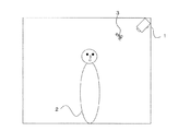
図2は、監視領域のイメージ図である。本実施の形態では、画像センサ1の撮像部40が監視領域の上方に設置された例を示しており、撮像部40は上方から下方に向けて所定の俯角で監視領域を撮像している。図2の例では、侵入者2と虫3が監視領域内に存在している状態を示している。
FIG. 2 is an image diagram of the monitoring area. In the present embodiment, an example in which the
図3及び図4は、各処理にて生成される画像を示したものである。図3(a)は、通常照明画像51の例であり、侵入者2と虫3が写されている。侵入者2と虫3は物体の大きさが異なるが、通常照明画像51では、撮像部40との距離の違いによって同じような大きさに写されている。図3(b)は、侵入者2と虫3とが存在しない状態で監視領域を撮像した通常背景画像52の例である。通常照明画像51と通常背景画像52との差分をとることにより、図3(c)に示すように、背景差分画像55が生成される。背景差分画像55では、侵入者2による変化領域2Aと虫3による変化領域3Aがそれぞれ抽出される。本発明は、これらの変化領域2A,3Aを「人間」であるか否かを判定する判定領域とする。
3 and 4 show images generated in each process. FIG. 3A is an example of the
図4(a)は、近傍照明画像53の例であり、侵入者2と虫3が写されている。近傍照明画像53では、侵入者2と虫3は同じように明るく写る物体であるが、写り方に違いがある。本実施の形態では、近傍照明画像53で明るく写る物体の写り方の違いに着目することにより、通常照明画像51から得られる特徴や近傍照明画像53で明るく写るという特徴だけでは区別が困難である侵入者2と虫3を区別できるようにする。
FIG. 4A is an example of the
具体的には、近傍照明画像53で一様に明るく写された物体を“虫”と判定し、一様に明るく映らない物体(鉛直方向の輝度にグラデーションがあるように写された物体)を“侵入者”と判定する。図2に示したように、虫3は体が小さいために体全体の撮像部40からの距離に大差がなく、体全体に一様に照明を受けて一様に反射して写る。これに対して、侵入者2である人間の身体は大きく、高さがあるため、身体全体の撮像部40からの距離が頭部から脚部に向かって遠くなり、身体全体に照明が一様に当たらず、一様に反射し難くなるので、上方から下方に向かって輝度にグラデーションがあるように写る。本実施の形態では、この差を利用して侵入者2と虫3とを区別する。
Specifically, an object that is uniformly brightly reflected in the near-
以下、画像センサ1を構成する照明部20、撮像制御部30、撮像部40、記憶部50、画像処理部60及び出力部70について詳細に説明する。
Hereinafter, the
照明部20は、夜間等、監視領域が暗い場合においても監視領域内に生じた変化を画像から検出できるように、監視領域に対して照明を施す。照明部20は、監視領域全域を照らすことができる照明用LED等の照明装置を含んで構成される。照明部20は、撮像制御部30による制御に基づき、監視領域に対して様々な明るさで照明を点灯させる。例えば、照明用LEDには近赤外LEDを用いる。
The
撮像制御部30は、照明部20と撮像部40の設定及び制御を行う。具体的には、撮像制御部30は、通常照明画像51と近傍照明画像53を取得するために、照明部20の点灯強度の制御を行い、撮像部40の露光制御を行う。撮像制御部30は、通常照明画像51の取得時には、監視領域全体が適度な明るさで撮像されるように照明部20及び撮像部40を制御する。例えば、撮像部40のシャッター速度を遅くし、照明部20の照明点灯強度を強める。また、撮像制御部30は、近傍照明画像53の取得時には、監視領域の撮像部40の近傍のみが明るく、遠方は暗く撮像されるように照明部20及び撮像部40を制御する。例えば、撮像部40のシャッター速度を通常照明画像51の撮像時より速くしたり、照明部20の照明点灯強度を通常照明画像51の撮像時より弱めたりする。なお、通常照明画像51及び近傍照明画像53の条件を満たすことができるなら、照明部20の照明点灯強度の制御、又は、撮像部40の露光制御のどちらか一方を制御するようにしてもよい。
The
撮像部40は、監視領域を撮像し、通常照明画像51と近傍照明画像53を記憶部50に出力する。撮像部40は、光学系、CCD素子又はC−MOS素子等の撮像素子、光学系部品、アナログ/デジタル変換器等を含んで構成される。撮像部40は、撮像制御部30からの制御に基づき、監視領域を撮影した撮像データ(通常照明画像51、近傍照明画像53等)をA/D変換したデジタル画像を記憶部50に出力する。撮像は、所定時間間隔で行うことが好適である。
The
記憶部50は、ROM(Read Only Memory)、RAM(Random Access Memory)等の半導体メモリ、ハードディスク等のメモリ装置で構成される。記憶部50は、撮像部40及び画像処理部60からアクセス可能であり、各種プログラムや各種データを記憶する。例えば、撮像部40で撮影された各種画像データや外部から設定される設定情報を記憶し、画像処理部60に対して出力する。設定情報は、外部より設定される画像センサ1の撮像部40の設置高や俯角などの情報である。
The
画像処理部60は、CPU(Central Processing Unit)、DSP(Digital Signal Processor)又はMCU(Micro Control Unit)等の演算装置により画像処理プログラムを実行することにより実現される。画像処理部60は、後述する各手段で処理を記述した画像処理プログラムを記憶部50から読み出して実行することにより、以下の各手段として機能する。画像処理部60は、撮像部40で撮影された監視画像を順に処理する。このとき、監視画像を古い画像から新しい画像へ向けて処理することが好ましい。例えば、監視画像を1フレーム毎順に処理してもよいし、数フレームおきに処理を行ってもよい。
The
画像処理部60は、判定領域抽出手段61、通常特徴算出手段62、差分領域抽出手段63、近傍特徴算出手段64、判定手段65及び背景画像更新手段66として機能する。
The
判定領域抽出手段61は、記憶部50に記憶された通常照明画像51から、侵入者か否かの判定対象となる領域(判定領域)を抽出する。例えば、通常照明画像51と通常背景画像52との間の輝度値の差分を求め、所定の閾値以上の差分のある領域を変化領域として抽出とする。変化領域は、差分が閾値以上の領域の画素値を“1”とし、閾値未満の領域の画素値を“0”とした二値画像としても表現することが好ましい。
The determination
さらに、判定領域抽出手段61は、抽出された変化領域に対して、同一物体による変化領域についてラベル付けを行う。具体的には、8連結で隣接する画素をひとまとまりとしてラベル領域とし、近接する複数のラベル領域が一定の大きさや位置関係にあれば同一物体によるものであるとして1つのラベル領域に設定する。また、判定領域抽出手段61は、複数の変化領域が所定距離以内にある場合、一定の大きさや位置関係にある変化領域を同一物体による変化領域であるとし、これらを1つ変化領域としてラベル付けしてもよい。本実施の形態では、1つのラベル領域を1つの判定領域として処理する。
Further, the determination
なお、判定領域の抽出は、通常照明画像51と通常背景画像52との差分に限らず、異なる時刻に撮像された複数の通常照明画像51のフレーム間差分が所定の輝度閾値以上である領域や、学習識別器等で判定の対象とするべき領域を抽出して判定領域としてもよい。
Note that the extraction of the determination area is not limited to the difference between the
また、判定領域抽出手段61は、異なる時刻に撮像された画像について、同一の物体によるラベル領域を対応付けることで、ラベル領域の追跡を実現する。具体的には、判定領域抽出手段61は、ラベル領域に対して、前回フレーム処理時の追跡物体との対応付けを行う。対応付けには、既存の追跡処理方法を適用することができる。また、前回の追跡物体と対応付けられない新たなラベル領域が発生した場合には新規追跡物体として追跡を開始し、過去のラベル領域と対応付けできるラベル領域が存在しない場合には追跡物体の追跡を終了する。
Further, the determination
通常特徴算出手段62は、各ラベル領域について「人間らしさ」を判定するための特徴量を求める。例えば、追跡対象である各ラベル領域に該当する物体の大きさ、形、傾き、色、移動範囲等の特徴量を抽出する。 The normal feature calculation means 62 obtains a feature amount for determining “humanity” for each label area. For example, feature quantities such as the size, shape, inclination, color, and movement range of the object corresponding to each label area to be tracked are extracted.
具体的には、物体の「大きさ」とは、画像内におけるラベル領域に外接する矩形の画像内の位置と、記憶部50に予め記憶されている撮像部40の設置高・俯角の情報から、ラベル領域の実空間での高さ及び幅を算出した値とすればよい。物体の「形」とは、画像内におけるラベル領域を楕円近似したときの画像内の短軸長と長軸長との比(短軸長÷長軸長)を算出した長短軸比とすればよい。物体の「傾き」とは、ラベル領域を楕円近似したときの水平方向(X軸方向)を0度としたときの長軸方向の傾きの角度を算出した長軸角度絶対値とすればよい。
Specifically, the “size” of the object is based on the position in the rectangular image circumscribing the label area in the image, and information on the installation height and depression angle of the
また、物体の「移動範囲」とは、追跡したラベル領域の重心位置の移動距離である。移動距離は、物体が監視領域に初めて出現した位置から現在の位置までの移動距離でもよいし、フレーム間における移動距離でもよい。また、距離の単位は画素でも良いし、記憶部50に記憶された撮像部40の設置高・俯角の情報を用いて、実空間での移動距離を算出してもよい。
The “movement range” of the object is the movement distance of the center of gravity position of the tracked label area. The movement distance may be a movement distance from the position where the object first appears in the monitoring area to the current position, or may be a movement distance between frames. The unit of distance may be a pixel, or the moving distance in real space may be calculated using information on the installation height and depression angle of the
また、通常特徴算出手段62において、通常照明画像51から判断できる「虫らしさ」を判定するための特徴量を求めてもよい。例えば、追跡しているラベル領域が画像の上下方向に移動した際の領域の面積の変化率(面積変化率)を特徴量として抽出する。このとき、上下方向に移動しても領域の面積が変化しない場合(面積変化率が低い場合)は飛行している虫らしい特徴となり、上下方向に移動したときに領域の面積が変化する場合(面積変化率が高い場合)は地面を移動する人間らしい特徴となる。また、例えば、ラベル領域内が通常照明画像51で通常背景画像52より明るく写された領域の比率である背景差分プラス点率を特徴量として抽出する。このとき、撮像部40の近傍にいる虫であれば撮像部40から離れた位置にいる人間よりも照明の影響を強く受けるので、この比率が高くなる。
Further, the normal feature calculation means 62 may obtain a feature amount for determining “insect-likeness” that can be determined from the
差分領域抽出手段63は、追跡物体(ラベル領域)毎に近傍照明画像53で明るく写された差分領域を抽出する。具体的には、各追跡物体(ラベル領域)について、近傍照明画像53と記憶部50に記憶されている近傍背景画像54との輝度値の差分を求め、差分値が所定の閾値以上となる領域を差分領域として抽出する。差分領域は、差分が閾値以上の領域の画素値を“1”とし、閾値未満の領域の画素値を“0”とした二値画像として表現することが好ましい。ここで、近傍照明画像53における追跡物体(ラベル領域)に対応する領域の輝度値が閾値以上となる領域を差分領域(二値)として抽出してもよい。
The difference
例えば、図4(a)に示す近傍照明画像53と図4(b)に示す近傍背景画像54の差分により、図4(c)に示すように、差分領域画像56が生成される。差分領域画像56には、侵入者による差分領域2Bと虫による差分領域3Bが抽出される。
For example, a
近傍特徴算出手段64は、追跡物体が撮像部40の近傍に存在することを表す近傍特徴量を算出する。近傍特徴量として、各ラベル領域に占める差分領域の割合、近傍照明画像53における差分領域内の輝度のバラツキが均一であるか均一でないか示す値が挙げられる。本実施の形態では、輝度が均一である程度として、差分領域内の輝度が一様であるかや鉛直方向のグラデーションが存在するかを判定する。本実施の形態において、鉛直方向のグラデーションであれば差分領域内の輝度が均一である程度は低く、一様であれば均一の程度は高くなる。このため、均一である程度が低い場合は人間らしい、均一である程度が高い場合は虫らしい近傍特徴となる。 本実施の形態では、図2のように撮像部40が監視領域の上方に設置され、上方から下方に向かって所定の俯角で監視領域を撮像するので、差分領域において輝度のグラデーションが鉛直方向に沿って上方から下方に向かって明から暗になるか否かを求める。ただし、撮像方向はこれに限定されるものではなく、例えば、撮像部40が監視領域を下方から上方に撮像するのであれば鉛直方向に下方から上方に向かって明から暗になるか否かを求めればよい。また、撮像部40が監視領域を地面と水平方向に撮像するのであれば、鉛直方向又は水平方向に沿って中央から外に向かって明から暗になるか否かを求めればよい。このように、近傍特徴量の求め方は、撮像部40の撮像方向に沿ったグラデーションを判定できるように適宜変更するようにすればよい。
The neighborhood
差分領域内における近傍照明画像53の輝度パターンを示すと、図4(d)に示すような画像57となり、画像領域2C、画像領域3C内の輝度分布が一様かグラデーションを有しているかを判定する。
When the luminance pattern of the
近傍特徴算出手段64における、差分領域内の輝度が均一である程度の判定方法を以下に詳細に説明する。
A determination method in which the brightness in the difference area is uniform to some extent in the neighborhood
ここでは、差分領域内の輝度分布が一様か否か、鉛直方向(上から下に)に輝度のグラデーションがあるか否かを判定する判定方法について説明する。以下、例として2種類の判定方法について説明する。 Here, a determination method for determining whether or not the luminance distribution in the difference area is uniform and whether or not there is a luminance gradation in the vertical direction (from top to bottom) will be described. Hereinafter, two types of determination methods will be described as examples.
第1の判定方法では、まず、差分領域の上から下に向かう方向をY軸方向として、Y軸の座標行(画素)毎の輝度最大値(平均値、中央値)を求める。そして、Y軸方向に沿って座標行毎に求めた輝度最大値(平均値、中央値)が、上から下に向かって変化しない場合は、一様であると判定し、上から下に向かって小さくなる場合はグラデーションであると判定する。具体的には、差分領域の上端行、中央行、下端行の輝度最大値(平均値、中央値)を用いて、上端行値と中央行値、中央行値と下端行値の差分絶対値が所定の閾値1未満の場合は、一様と判定する。また、(上端行値−中央行値)、(中央行値−下端行値)の値がそれぞれ所定の閾値2以上の場合、グラデーションであると判定する。
In the first determination method, first, the luminance maximum value (average value, median value) for each coordinate line (pixel) on the Y axis is obtained with the direction from the top to the bottom of the difference area as the Y axis direction. If the maximum luminance value (average value, median value) obtained for each coordinate line along the Y-axis direction does not change from the top to the bottom, it is determined that the brightness is uniform and the direction is from top to bottom. If it becomes smaller, the gradation is determined. Specifically, the absolute value of the difference between the top row value and the middle row value, and the middle row value and the bottom row value using the maximum luminance values (average value, median value) of the top row, middle row, and bottom row of the difference area. Is less than the
第2の方法では、まず、差分領域の重心Y座標と外接矩形上端・下端Y座標を記憶部50に記憶する。次に、近傍照明画像53から差分領域を抽出したときの二値化のための閾値より、少し大きな閾値で再度二値領域を抽出し、その領域の重心Y座標と外接矩形上端・下端Y座標を記憶部50に記憶する。さらに少し大きな閾値で二値領域を抽出し、その領域の重心Y座標と外接矩形上端・下端Y座標を記憶部50に記憶する。このように、二値化のための閾値を少しずつ大きくし、抽出される領域の面積が少しずつ小さくなるように二値領域を抽出する処理を繰り返す。
In the second method, first, the center of gravity Y coordinate and the upper and lower Y coordinates of the circumscribed rectangle are stored in the
二値化の閾値を上げていった際に、(1)重心Y座標が動かない(動きが所定閾値未満である)、(2)外接矩形下端Y座標が動かない(動きが所定閾値未満である)及び(3)外接矩形上端Y座標が動かない(動きが所定閾値未満である)の条件を満たすときは、一様であると判定する。一方、(4)重心Y座標が上に移動する(動きが所定閾値以上である)、(5)外接矩形下端Y座標が上に移動する(動きが所定閾値以上である)及び(6)外接矩形上端Y座標が動かない(動きが所定閾値未満である)の条件を満たすときは、グラデーションがあると判定する。 When the threshold for binarization is increased, (1) the center of gravity Y coordinate does not move (the movement is less than the predetermined threshold), (2) the circumscribed rectangle lower end Y coordinate does not move (the movement is less than the predetermined threshold). (3) and (3) when the condition that the upper end Y coordinate of the circumscribed rectangle does not move (the movement is less than a predetermined threshold) is satisfied, it is determined to be uniform. On the other hand, (4) the center-of-gravity Y coordinate moves upward (movement is greater than or equal to a predetermined threshold), (5) the circumscribed rectangle lower end Y coordinate moves upward (movement is greater than or equal to a predetermined threshold), and (6) circumscribed When the condition that the upper end Y coordinate of the rectangle does not move (the movement is less than a predetermined threshold) is satisfied, it is determined that there is gradation.
なお、輝度分布が一様かグラデーションを有しているかを判定する判定方法については、これらの方法に限定されるものではなく、他の方法によって判定してもよい。 Note that the determination method for determining whether the luminance distribution is uniform or has gradation is not limited to these methods, and may be determined by other methods.
近傍照明画像53における差分領域内の輝度が均一である程度を判定する方法として、差分領域内の各画素の輝度の分散値が小さいほどより均一であると判定してもよい。具体的には、差分領域内の各画素の輝度の分散値を求め、分散値が所定の閾値以上である場合にはその差分領域は均一でないと判定し、閾値未満である場合には均一であると判定する。さらに、この判定の条件を上述した「一様判定」や「グラデーション判定」の条件に追加してもよい。
As a method of determining a certain degree of uniform luminance in the difference area in the
判定手段65は、通常特徴算出手段62及び近傍特徴算出手段64から算出される特徴量を用いて、追跡物体ごとの「人間らしさ」を表す人属性値(検出対象属性)や「虫らしさ」を表す虫属性値(非検出対象属性)の算出処理を行う。そして、各属性値を用いて、監視領域内に人間(侵入者)がいるか否かの判定を行う。
The
例えば、通常特徴算出手段62で求めた特徴量を用いて、物体の「大きさ」に基づいて人属性値を設定する。図6に、人属性値を決定するための人属性値要素1の設定方法を示す。ここでは、特徴量を人体である可能性が高いほど1に近づき、低いほど0に近づくように正規化した人属性値要素として求めている。
For example, the human attribute value is set based on the “size” of the object using the feature amount obtained by the normal feature calculating means 62. FIG. 6 shows a setting method of the human
例えば、物体の実面積が人間らしい大きさに近いほど人属性値要素1を大きな値に設定する。また、物体の「形」に基づいて人属性値を設定してもよい。例えば、物体の長短軸比が縦長な形状を示すものであれば人属性値要素2に大きな値を設定する。また、物体の「傾き」に基づいて人属性値を設定してもよい。例えば、物体の長軸角度絶対値が大きいほど人属性値要素3を大きな値に設定する。
For example, the human
判定手段65は、複数の人属性値要素を用いて、追跡物体(ラベル領域)毎に「人間らしさ」を表わす人属性値を算出する。例えば、複数の人属性値要素を乗算して、人属性値=人属性値要素1×人属性値要素2×人属性値要素3・・とする。
The
また、通常特徴算出手段62で求めた特徴量や近傍特徴算出手段64で求めた近傍特徴量を用いて、追跡物体毎に「虫らしさ」を表わす虫属性値を算出する。図6に、虫属性値を決定するための虫属性値要素1の設定方法を示す。ここでは、特徴量を虫である可能性が高いほど1に近づき、低いほど0に近づくように正規化した虫属性値要素として求めている。
Also, by using the feature quantity obtained by the normal feature calculation means 62 and the neighborhood feature quantity obtained by the neighborhood feature calculation means 64, an insect attribute value representing “insect-likeness” is calculated for each tracking object. FIG. 6 shows a method of setting the insect
例えば、追跡物体のラベル領域が画像の上下方向に移動した際の領域の面積変化率が小さいほど虫属性値要素1を大きな値とする。また、例えば、虫であれば変化領域内が通常照明画像51で通常背景画像52より明るく写されるので、この比率が高い領域内の画素において通常照明画像51の輝度値から通常背景画像52の輝度値を引いた値がプラスとなる画素数(領域面積)を変化領域全体の画素数(領域面積)で割った背景差分プラス点率に応じて虫属性値要素2を決定する。
For example, the insect
さらに、近傍特徴算出手段64で求めた特徴量を用いて虫属性値を算出する。虫であれば、近傍照明画像53において変化領域に対応する領域のうち差分領域として抽出される領域が大きくなる。そこで、例えば、各ラベル領域に含まれる変化領域毎に対応する差分領域の大きさを変化領域の大きさで割った差分領域包含率を算出し、この差分領域包含率に応じて虫属性値要素3を決定する。また、撮像部40の近傍にいる虫であれば差分領域は一様な明るさとなり、撮像部40から離れた位置にいる人間であればグラデーションになる。そこで、差分領域に対応するラベル領域について輝度分布の度合いである差分領域輝度分布度を求める。差分領域輝度分布度は、一様であれば「1」、グラデーションであれば「0」、どちらでもなければ「0.5」となる特徴量であり、虫属性値要素4は、差分領域輝度分布度が大きいほど大きな値となる。
Further, the insect attribute value is calculated using the feature amount obtained by the neighborhood feature calculating means 64. If it is a worm, the area extracted as the difference area in the area corresponding to the change area in the
なお、差分領域輝度分布度は輝度が一様であるか、グラデーションであるか、どちらでもないかに応じた固定値でなく、その度合いに応じた値としても良い。例えば、グラデーションがあると判定された場合に、グラデーションの度合いに応じて差分領域輝度分布度の値を変えてもよい。例えば、輝度値が小さくなる振り幅に応じて差分領域輝度分布度の値を0〜0.5の間で変動させる。具体的には、差分領域上端での輝度最大値(平均値、中央値)と差分領域の閾値の差をD、差分領域上端での輝度最大値(平均値、中央値)と下端での輝度最大値(平均値、中央値)の差をdとして、0.5×(1−d/D)を差分領域輝度分布度とすればよい。こうすることにより、グラデーションの度合いに応じた属性値を算出することもできる。一様側についても同様な処理を行ってもよい。例えば、座標の移動具合や分散値に応じて変動させるなどすればよい。 Note that the difference area luminance distribution degree is not a fixed value depending on whether the luminance is uniform or gradation, but may be a value according to the degree. For example, when it is determined that there is a gradation, the value of the difference area luminance distribution degree may be changed according to the degree of gradation. For example, the value of the difference area luminance distribution degree is varied between 0 and 0.5 according to the amplitude with which the luminance value becomes small. Specifically, D is the difference between the maximum brightness value (average value, median value) at the top of the difference area and the threshold value of the difference area, and the maximum brightness value (average value, median value) at the top edge of the difference area and the brightness at the bottom edge. The difference between the maximum values (average value, median) may be d, and 0.5 × (1−d / D) may be the difference area luminance distribution degree. By doing so, it is possible to calculate an attribute value corresponding to the degree of gradation. Similar processing may be performed on the uniform side. For example, it may be varied according to the degree of movement of coordinates or the variance value.
判定手段65は、複数の虫属性値要素を用いて、追跡物体(ラベル領域)毎に「虫らしさ」を表わす虫属性値を算出する。例えば、複数の虫属性値要素を乗算して、虫属性値=虫属性値要素1×虫属性値要素2×虫属性値要素3×虫属性値要素4・・・とする。
The
本実施の形態では、近傍特徴算出手段64で求めた近傍特徴を虫属性値に用いたが、人属性値に用いてもよい。例えば、グラデーションであれば人属性値を高くし、一様であれば人属性値を低くするようにしてもよい。
In the present embodiment, the neighborhood feature obtained by the
判定手段65は、追跡物体(ラベル領域)毎に「人間」か「虫」かを判定する。追跡物体の人属性値が大きく、虫属性値が小さい、かつ、移動量も大きい場合、当該追跡物体を「人間」と判定する。また、1フレームにて判定するのではなく、数フレーム分の属性値を蓄積して判定を行うようにしてもよい。つまり、虫属性値が大きいと検出対象である人間と判定しにくくなり、虫属性値が小さいと検出対象と判定しやすくなる。 The determination means 65 determines whether the person is a “human” or “insect” for each tracking object (label region). When the human attribute value of the tracking object is large, the insect attribute value is small, and the movement amount is large, the tracking object is determined as “human”. Further, the determination may be made by accumulating attribute values for several frames instead of determining by one frame. That is, if the insect attribute value is large, it is difficult to determine that the person is the detection target, and if the insect attribute value is small, it is easy to determine the detection target.
背景画像更新手段66は、撮像部40にて撮影された各種画像と判定手段65の判定結果などを用いて、通常背景画像52及び近傍背景画像54を更新する。背景画像更新時は、処理対象となっていた通常照明画像51と近傍照明画像53それぞれの画像を、記憶部50に記憶されている通常背景画像52及び近傍背景画像54に代わる新たな通常背景画像52及び近傍背景画像54として更新する。
The background
背景画像更新手段66は、判定手段65の結果を用いて更新処理を行うことが好適である。背景画像更新手段66は、監視領域に人間がいると判定された場合には背景更新を行わず、人間がいないと判定された場合には背景更新を行う。
It is preferable that the background
また、背景画像の更新方法はこれに限らず、人はいないが追跡物体がある場合は背景更新頻度を下げるなどしてもよい。また、一定時間間隔で更新する方法や追跡物体がないと判断された画像を更新する方法、照明変動を検知した場合に更新する方法などを用いてもよい。 In addition, the background image update method is not limited to this, and if there is a tracking object but no person, the background update frequency may be lowered. Further, a method of updating at regular time intervals, a method of updating an image determined to have no tracking object, a method of updating when an illumination change is detected, or the like may be used.
出力部70は、判定手段65で監視領域内に侵入者(人間)がいると判定された場合、その情報を画像センサ1の外部に出力する。外部の装置では出力結果に基づき、警報などを発する。
When the
次に、図5のフローチャートを参照して、本実施形態の画像センサ1における画像処理による監視について説明する。
Next, monitoring by image processing in the
ステップS1では、撮像部40で監視領域を撮影する。撮像する画像は、通常照明画像51と近傍照明画像53の2種類である。通常照明画像51の撮像時には、監視領域全体が十分明るく撮像されるように、撮像部40の露光調整や照明部20の照明点灯強度を設定して撮像を行う。また、近傍照明画像53の撮像時には、撮像部40の近傍のみが明るく撮像されるように、撮像部40の露光調整や照明部20の照明点灯強度を設定して撮像を行う。撮像部40の露光設定、及び、照明部20の照明点灯強度設定は撮像制御部30から出力される信号によって行われる。通常照明画像51及び近傍照明画像53は、例えば、1/60秒ごとに交互に撮像され、2種類の画像が揃った時点で以降の処理に移行する。
In step S <b> 1, the monitoring area is imaged by the
ステップS2では、判定領域抽出手段61において、通常照明画像51と記憶部50に記憶されている通常背景画像52との差分の絶対値を閾値処理し、通常照明画像51から変化領域を2値画像として抽出する。
In step S <b> 2, the determination
ステップS3では、判定領域抽出手段61にて、関連のある変化領域を纏めてラベル付けを行いラベル領域を設定する。本実施の形態ではラベル領域を判定領域とする。
In step S3, the determination
ステップS4では、判定領域抽出手段61にて、各ラベル領域に対して前回の追跡物体との対応付けを行う。また、前回の追跡物体と対応付けられないラベル領域は新規追跡物体として追跡を開始し、過去のラベル領域と対応付けられない追跡物体は追跡を終了する。
In step S4, the determination
以降、ステップS5及びステップS12では、追跡物体(ラベル領域)毎にステップS6からS11までの処理を繰り返す設定を行う。これにより、ステップS6からS11の処理は、追跡物体に対して追跡物体の数だけ実行される。 Thereafter, in step S5 and step S12, the setting from step S6 to S11 is repeated for each tracking object (label region). Thereby, the process of step S6 to S11 is performed with respect to the tracking object by the number of tracking objects.
ステップS6では、通常特徴算出手段62にて、追跡物体ごとに「人間らしさ」及び「虫らしさ」を判定するために用いられる特徴量を求める。例えば、追跡物体の大きさ、形・色及び移動範囲等を特徴量として算出する。また、ラベル領域が画像の上下方向に移動した際の領域の面積変化率、ラベル領域内が通常照明画像51で通常背景画像52より明るく写された領域の比率である背景差分プラス点率を特徴量として算出する。
In step S <b> 6, the normal
ステップS7では、差分領域抽出手段63にて、追跡物体ごとに、近傍照明画像53で明るく写された領域(差分領域)を抽出する。ステップS8では、差分領域がある場合にはステップS9に処理を移行させ、差分領域がない場合にはステップS10に処理を移行させる。
In step S <b> 7, the difference
ステップS9では、近傍特徴算出手段64において、追跡物体ごとに、近傍特徴量を算出する。具体的には、差分領域の大きさやラベル領域に占める差分領域の比率である差分領域包含率、差分領域内の輝度が一様であるか上下のグラデーションであるかを示す差分領域輝度分布度を算出する。
In step S <b> 9, the neighborhood
ステップS10では、ステップS6及びS9において画像処理部60の通常特徴算出手段62や近傍特徴算出手段64で算出された追跡物体の特徴量を用いて、追跡物体の「人間らしさ」を表す人属性値や「虫らしさ」を表す虫属性値を算出する。
In step S10, the human attribute value representing the “humanity” of the tracked object using the feature quantities of the tracked object calculated by the normal
ステップS11では、算出された属性値などを用いて、判定手段65にて、追跡物体が人間であるかどうかを判定する。追跡物体の人属性値が大きく、虫属性値が小さい、かつ、移動量も大きい場合、またはそのような状態が連続している場合は、処理対象とした追跡物体(ラベル領域)を「人間」と判定する。
In step S11, using the calculated attribute value or the like, the
このような処理を追跡物体(ラベル領域)毎に行い、各追跡物体が検出対象である人間(侵入者)であるか否かを判定する。すべての追跡対象(ラベル領域)について判定が終了するとステップS13に処理を移行させる。 Such processing is performed for each tracking object (label region), and it is determined whether or not each tracking object is a person (intruder) that is a detection target. When the determination is completed for all tracking targets (label areas), the process proceeds to step S13.
ステップS13では、背景画像更新手段66は、記憶部50に記憶されている通常背景画像52及び近傍背景画像54を更新する。上述したように、背景画像更新手段66のよる更新は、監視領域に人間がいると判定された場合には背景更新を行わず、人間がいないと判定された場合には背景更新を行うものとしてもよい。
In step S <b> 13, the background
ステップS14では、判定手段65にて、人間と判定された追跡物体があった場合には処理をステップS15に移行させ、そうでない場合にはステップS1に処理を戻して、新たなフレームについての処理を開始する。ステップS15では、出力部70は、判定手段65で監視領域内に侵入者(人間)がいると判定されたことを示す情報を画像センサ1の外部に出力する。外部の装置では出力結果に基づき、警報などを発する。
In step S14, if there is a tracking object determined by the determination means 65 as a human, the process proceeds to step S15. If not, the process returns to step S1 to process a new frame. To start. In step S <b> 15, the
以上のように、本発明によれば、撮像部近傍にいる虫等の非検出対象物と撮像部から離れた位置にいる侵入者等の検出対象物を明確に区別することができる。 As described above, according to the present invention, it is possible to clearly distinguish non-detection objects such as insects in the vicinity of the imaging unit and detection objects such as intruders at a position away from the imaging unit.
1 画像センサ、2 侵入者、2A,3A 変化領域、2B,3B 差分領域、2C,3C 画像領域、20 照明部、30 撮像制御部、40 撮像部、50 記憶部、51 通常照明画像、52 通常背景画像、53 近傍照明画像、54 近傍背景画像、55 背景差分画像、56 差分領域画像、57 画像、60 画像処理部、61 判定領域抽出手段、62 通常特徴算出手段、63 差分領域抽出手段、64 近傍特徴算出手段、65 判定手段、66 背景画像更新手段、70 出力部。 1 image sensor, 2 intruder, 2A, 3A change area, 2B, 3B difference area, 2C, 3C image area, 20 illumination unit, 30 imaging control unit, 40 imaging unit, 50 storage unit, 51 normal illumination image, 52 normal Background image, 53 Neighborhood illumination image, 54 Neighborhood background image, 55 Background difference image, 56 Difference area image, 57 Image, 60 Image processing unit, 61 Determination area extraction means, 62 Normal feature calculation means, 63 Difference area extraction means, 64 Neighborhood feature calculation means, 65 determination means, 66 background image update means, 70 output unit.
Claims (2)
前記画像処理部は、
前記照明部を点灯して撮像された画像と前記背景画像との差分領域を抽出する差分領域抽出手段と、
前記照明部を点灯して撮像された画像から前記差分領域内の輝度が均一である程度を特徴量として求める特徴算出手段と、
前記特徴量を用いて前記均一の程度が低い場合は、高い場合よりも前記検出対象と判定しやすくする判定手段と、
を備えることを特徴とする画像センサ。 An imaging unit that captures an image of the monitoring region, an illumination unit that illuminates the monitoring region, a detection target that is located at a position away from the imaging unit based on a change in an image captured by the imaging unit, and the imaging unit An image processing unit that identifies a non-detection target that is present near the storage unit, and a storage unit that stores, as a background image, an image that is captured by lighting the illumination unit and does not include the detection target An image sensor,
The image processing unit
A difference area extracting means for extracting a difference area between the image captured by lighting the illumination unit and the background image;
A feature calculation means for obtaining, as a feature amount, a certain degree of uniform brightness in the difference area from an image captured by turning on the illumination unit;
When the degree of the uniform with the feature quantity is low, a determination means for easily determining that the detection target than high,
An image sensor comprising:
前記特徴算出手段は、前記差分領域内の輝度が鉛直方向に変化しているほど均一の程度が低くなるように前記特徴量を算出することを特徴とする画像センサ。 The image sensor according to claim 1,
The image sensor is characterized in that the feature calculation means calculates the feature amount such that the degree of uniformity decreases as the luminance in the difference region changes in the vertical direction.
Priority Applications (1)
| Application Number | Priority Date | Filing Date | Title |
|---|---|---|---|
| JP2013126159A JP6155106B2 (en) | 2013-06-14 | 2013-06-14 | Image sensor |
Applications Claiming Priority (1)
| Application Number | Priority Date | Filing Date | Title |
|---|---|---|---|
| JP2013126159A JP6155106B2 (en) | 2013-06-14 | 2013-06-14 | Image sensor |
Publications (3)
| Publication Number | Publication Date |
|---|---|
| JP2015001836A JP2015001836A (en) | 2015-01-05 |
| JP2015001836A5 JP2015001836A5 (en) | 2016-06-30 |
| JP6155106B2 true JP6155106B2 (en) | 2017-06-28 |
Family
ID=52296326
Family Applications (1)
| Application Number | Title | Priority Date | Filing Date |
|---|---|---|---|
| JP2013126159A Active JP6155106B2 (en) | 2013-06-14 | 2013-06-14 | Image sensor |
Country Status (1)
| Country | Link |
|---|---|
| JP (1) | JP6155106B2 (en) |
Cited By (1)
| Publication number | Priority date | Publication date | Assignee | Title |
|---|---|---|---|---|
| JP7253548B2 (en) | 2018-07-05 | 2023-04-06 | 本州化学工業株式会社 | (Meth)acrylate terminated polycarbonate oligomer |
Families Citing this family (1)
| Publication number | Priority date | Publication date | Assignee | Title |
|---|---|---|---|---|
| JP7328778B2 (en) * | 2019-03-29 | 2023-08-17 | セコム株式会社 | Image processing device and image processing program |
Family Cites Families (4)
| Publication number | Priority date | Publication date | Assignee | Title |
|---|---|---|---|---|
| JP3423861B2 (en) * | 1997-07-17 | 2003-07-07 | 株式会社日立製作所 | Method and apparatus for monitoring a moving object |
| JP2002032759A (en) * | 2000-07-19 | 2002-01-31 | Mitsubishi Electric Corp | Monitor |
| JP3862558B2 (en) * | 2001-11-30 | 2006-12-27 | セコム株式会社 | Image sensor and surveillance camera device |
| JP5761954B2 (en) * | 2010-10-13 | 2015-08-12 | セコム株式会社 | Image sensor |
-
2013
- 2013-06-14 JP JP2013126159A patent/JP6155106B2/en active Active
Cited By (1)
| Publication number | Priority date | Publication date | Assignee | Title |
|---|---|---|---|---|
| JP7253548B2 (en) | 2018-07-05 | 2023-04-06 | 本州化学工業株式会社 | (Meth)acrylate terminated polycarbonate oligomer |
Also Published As
| Publication number | Publication date |
|---|---|
| JP2015001836A (en) | 2015-01-05 |
Similar Documents
| Publication | Publication Date | Title |
|---|---|---|
| JP2008158922A (en) | Eyelid detection apparatus, eyelid detection method, and program | |
| JP4611776B2 (en) | Image signal processing device | |
| JP6548686B2 (en) | Image comparison device | |
| EP2000998B1 (en) | Flame detecting method and device | |
| JP5530530B2 (en) | Vehicle periphery monitoring device | |
| JP2006262242A (en) | Image signal processing apparatus | |
| JP4865328B2 (en) | Image sensor | |
| JP4656977B2 (en) | Sensing device | |
| JP4491360B2 (en) | Image signal processing device | |
| JP2000184359A (en) | Monitoring device and system therefor | |
| JP5761954B2 (en) | Image sensor | |
| JP6155106B2 (en) | Image sensor | |
| JP6189284B2 (en) | Image sensing device | |
| JP3294468B2 (en) | Object detection method in video monitoring device | |
| JP6275022B2 (en) | Image monitoring device | |
| JP7092616B2 (en) | Object detection device, object detection method, and object detection program | |
| JP6133700B2 (en) | Image sensor | |
| JP4765113B2 (en) | Vehicle periphery monitoring device, vehicle, vehicle periphery monitoring program, and vehicle periphery monitoring method | |
| JP4828265B2 (en) | Image sensor | |
| JP4641902B2 (en) | Image sensor | |
| WO2018110377A1 (en) | Video monitoring device | |
| JP3736836B2 (en) | Object detection method, object detection apparatus, and program | |
| JP7328778B2 (en) | Image processing device and image processing program | |
| JP6124739B2 (en) | Image sensor | |
| JP6093270B2 (en) | Image sensor |
Legal Events
| Date | Code | Title | Description |
|---|---|---|---|
| A521 | Request for written amendment filed |
Free format text: JAPANESE INTERMEDIATE CODE: A523 Effective date: 20160513 |
|
| A621 | Written request for application examination |
Free format text: JAPANESE INTERMEDIATE CODE: A621 Effective date: 20160513 |
|
| A977 | Report on retrieval |
Free format text: JAPANESE INTERMEDIATE CODE: A971007 Effective date: 20170420 |
|
| TRDD | Decision of grant or rejection written | ||
| A01 | Written decision to grant a patent or to grant a registration (utility model) |
Free format text: JAPANESE INTERMEDIATE CODE: A01 Effective date: 20170523 |
|
| A61 | First payment of annual fees (during grant procedure) |
Free format text: JAPANESE INTERMEDIATE CODE: A61 Effective date: 20170605 |
|
| R150 | Certificate of patent or registration of utility model |
Ref document number: 6155106 Country of ref document: JP Free format text: JAPANESE INTERMEDIATE CODE: R150 |
|
| R250 | Receipt of annual fees |
Free format text: JAPANESE INTERMEDIATE CODE: R250 |
|
| R250 | Receipt of annual fees |
Free format text: JAPANESE INTERMEDIATE CODE: R250 |
|
| R250 | Receipt of annual fees |
Free format text: JAPANESE INTERMEDIATE CODE: R250 |
|
| R250 | Receipt of annual fees |
Free format text: JAPANESE INTERMEDIATE CODE: R250 |
|
| R250 | Receipt of annual fees |
Free format text: JAPANESE INTERMEDIATE CODE: R250 |