JP6154776B2 - Setting application system, setting application method, communication apparatus, server apparatus, and computer program - Google Patents
Setting application system, setting application method, communication apparatus, server apparatus, and computer program Download PDFInfo
- Publication number
- JP6154776B2 JP6154776B2 JP2014089706A JP2014089706A JP6154776B2 JP 6154776 B2 JP6154776 B2 JP 6154776B2 JP 2014089706 A JP2014089706 A JP 2014089706A JP 2014089706 A JP2014089706 A JP 2014089706A JP 6154776 B2 JP6154776 B2 JP 6154776B2
- Authority
- JP
- Japan
- Prior art keywords
- information
- setting information
- communication device
- setting
- model name
- Prior art date
- Legal status (The legal status is an assumption and is not a legal conclusion. Google has not performed a legal analysis and makes no representation as to the accuracy of the status listed.)
- Active
Links
Images


Description
本発明は、異なる装置間において、一方の装置に設定された情報を他方の装置に適用する技術分野に関する。 The present invention relates to a technical field in which information set in one device is applied to the other device between different devices.
複数の通信ネットワーク間を中継する通信装置(以下、本願では、「ルータ」と称する)は、利用者の利用形態に応じて様々な種類が存在する。一例として、ルータには、大別して、有線LAN(Local_Area_Network)ルータと無線LANルータとがある。例えば、この無線LANルータを用いてインターネットを利用する場合に、利用者は、無線LANルータに対して様々な情報を設定(以下、本願では「設定情報」と称する)する必要がある。一例として、設定情報は、ネットワーク名を示すSSID(Service_Set_Identifier)、セキュリティキーである暗号化キー、PPPoE(Point−to−point_protocol_over_Ethernet)認証ID(Identifier)及びパスワードなどを示す情報を含む。また、例えば、アクセスを制限する機能の一つであるMAC(Media_Access_Control)アドレスフィルタリングを利用する場合に、当該設定情報は、SSIDなどの情報だけでなく、MACアドレスフィルタリングに関する情報をも含む。このように、無線LANルータは、利便性の向上、セキュリティ対策を目的として、様々な機能を有すると共に、その機能に関する情報が設定されている。 There are various types of communication apparatuses that relay between a plurality of communication networks (hereinafter referred to as “routers” in the present application) depending on the usage mode of the user. As an example, the router is roughly classified into a wired LAN (Local_Area_Network) router and a wireless LAN router. For example, when using the Internet using this wireless LAN router, the user needs to set various information for the wireless LAN router (hereinafter referred to as “setting information” in the present application). As an example, the setting information includes SSID (Service_Set_Identifier) indicating a network name, an encryption key as a security key, PPPoE (Point-to-point_protocol_over_Ethernet) authentication ID (Identifier), a password, and the like. For example, when using MAC (Media_Access_Control) address filtering, which is one of functions for restricting access, the setting information includes not only information such as SSID but also information related to MAC address filtering. As described above, the wireless LAN router has various functions and information on the functions is set for the purpose of improving convenience and security measures.
ここで、本願出願に先立って存在する代表的な関連技術としては、例えば、特許文献1乃至特許文献3がある。
Here, representative related technologies existing prior to the present application include, for example,
特許文献1は、IP(Internet_Protocol)ネットワークシステムに関する技術を開示する。
特許文献1は、一般的に知られた広域仮想プライベートネットワーク(Internet_Protocol−Virtual_Private_Network:以降、「IP−VPN」と称する)において、IPネットワークサービスを規定する情報を、利用者が設定及び変更する技術を開示する。より具体的に、ネットワーク事業者により管理されたサーバ装置に当該サービスを規定する情報が格納されている場合に、利用者は、当該サーバ装置にアクセスすると共に、そのサーバ装置に格納された当該サービスを規定する情報を変更する。このように、特許文献1は、IPネットワークサービスに関する設定を、利用者自らが行うことができる。
特許文献2は、アクセスポイント、無線通信装置及びそれらの制御方法に関する技術を開示する。
特許文献2に開示された無線通信装置は、認証処理に用いるアカウントとパスワードとを含む情報を、着脱式の記憶装置に記憶する。また、当該無線通信装置と異なる他の無線通信装置において認証処理を行う場合に、当該他の無線通信装置は、着脱式の記憶装置に記憶された情報を用いて認証処理を実行する。これにより、例えば、当該無線通信装置を利用する利用者は、当該着脱式の記憶装置を用いてアクセスポイントと無線通信装置との認証を、容易に行うことができる。
The wireless communication device disclosed in
特許文献3は、ネットワーク同期システム及び情報処理装置に関する技術を開示する。特許文献3に開示されたネットワーク同期システムは、ネットワークを介して通信可能に接続された複数のデジタルカラー複合機を備える。当該デジタルカラー複合機は、自装置の設定情報を記憶する設定情報記憶部と、その設定情報を共有する同期用共有記憶部と、設定情報記憶部に記憶された設定情報を更新する同期制御部とを有する。当該同期制御部は、自装置の同期用共有記憶部に記憶された設定情報と、自装置と異なる他のデジタルカラー複合機の同期用共有記憶部に記憶された設定情報との比較結果に基づき、該設定情報を更新する。これにより、複数のデジタルカラー複合機は、設定情報を同期することができる。 Patent Document 3 discloses a technique related to a network synchronization system and an information processing apparatus. The network synchronization system disclosed in Patent Document 3 includes a plurality of digital color multifunction peripherals that are communicably connected via a network. The digital color MFP includes a setting information storage unit that stores setting information of the device itself, a synchronization shared storage unit that shares the setting information, and a synchronization control unit that updates the setting information stored in the setting information storage unit And have. The synchronization control unit is based on a comparison result between the setting information stored in the synchronization shared storage unit of the own device and the setting information stored in the synchronization shared storage unit of another digital color MFP different from the own device. The setting information is updated. Thereby, the plurality of digital color multifunction peripherals can synchronize the setting information.
上述において説明した特許文献1乃至特許文献3だけでなく、例えば、特許文献4などの認証処理に用いるアカウントやパスワードを管理する技術は、多岐にわたり存在する。
There are a wide variety of techniques for managing accounts and passwords used for authentication processing, such as
上述したように、無線LANルータには、SSID、暗号化キー、PPPoEの認証ID及びパスワードなどを含む情報が設定されている。そのため、既に設置された無線LANルータを、その無線LANルータと異なる他の無線LANルータに置き換える場合に、利用者は、既存の無線LANルータに設定された情報に基づいて、当該他の無線LANルータに手動により設定を変更する必要がある。 As described above, information including the SSID, the encryption key, the PPPoE authentication ID and the password is set in the wireless LAN router. Therefore, when a wireless LAN router that has already been installed is replaced with another wireless LAN router that is different from the wireless LAN router, the user can use the other wireless LAN router based on information set in the existing wireless LAN router. You need to change the settings manually on the router.
しかしながら、スマートフォンなどの無線LAN機能を有する端末装置を用いて係る他の無線LANルータの設定を変更する場合に、まず、利用者は、工場出荷時に設定されたSSIDなどを用いて他の無線LANルータと端末装置との間において接続を確立する。その後、利用者は、当該他の無線LANルータの設定を変更する必要がある。即ち、利用者は、一旦、当該他の無線LANルータと端末装置との間において接続を確立する作業が必要となるため、非常に手間がかかる虞がある。 However, when changing the setting of another wireless LAN router using a terminal device having a wireless LAN function such as a smartphone, first, the user uses another wireless LAN using the SSID set at the time of factory shipment. A connection is established between the router and the terminal device. Thereafter, the user needs to change the setting of the other wireless LAN router. That is, since the user needs to establish a connection between the other wireless LAN router and the terminal device, there is a possibility that it will be very time-consuming.
この問題に対して、無線LANルータでは、係る設定情報を端末装置に保存する機能を備える機器も存在する。しかしながら、例えば、当該無線LANルータと係る他の無線LANルータとを製造するメーカや機種が異なる場合に、当該端末装置に保存した設定情報のデータファイルの構成は異なる可能性がある。そのため、利用者は、当該端末装置に設定情報を保存した場合であっても、その設定情報を当該他の無線LANルータに適用することができない。 For this problem, wireless LAN routers also include devices having a function of storing such setting information in a terminal device. However, for example, when the manufacturer and model of the wireless LAN router and the other wireless LAN router are different, the configuration of the data file of the setting information stored in the terminal device may be different. Therefore, even if the user saves the setting information in the terminal device, the user cannot apply the setting information to the other wireless LAN router.
特許文献1には、IPネットワークサービスを規定する情報を更新することが記載されているに留まる。また、特許文献2に開示された技術では、着脱式の記憶装置が必要となるだけでなく、その記憶装置を着脱可能なインタフェースを無線通信装置が備える必要がある。そのため、無線通信装置の製造コストは高くなる可能性がある。また、利用者は、無線通信装置において認証処理を行うに際して、記憶装置を着脱する必要がある。即ち、利用者の利便性は低下する虞がある。
特許文献3に開示されたネットワーク同期システムは、複数のデジタルカラー複合機において設定情報を同期することが記載されているに留まる。また、設定情報を同期するに際して、複数のデジタルカラー複合機は、通信ネットワークを介して通信可能に接続している必要がある。即ち、ネットワーク同期システムでは、既に設置された機器から新たに設置する機器にリプレイスすることについて、考慮されておらず何ら述べられていない。 The network synchronization system disclosed in Patent Document 3 only describes that setting information is synchronized in a plurality of digital color multifunction peripherals. Further, when synchronizing the setting information, the plurality of digital color MFPs need to be communicably connected via a communication network. That is, in the network synchronization system, replacement of an already installed device to a newly installed device is not considered and nothing is described.
本発明は、煩わしい操作を必要とすることなく、特定の装置に設定された情報を所望の装置に適用することが可能な設定適用システム等を提供することを主たる目的とする。 A main object of the present invention is to provide a setting application system that can apply information set in a specific device to a desired device without requiring a troublesome operation.
上記の課題を達成すべく、本発明の一態様に係る設定適用システムは、以下の構成を備えることを特徴とする。 In order to achieve the above object, a setting application system according to an aspect of the present invention includes the following configuration.
即ち、本発明の一態様に係る設定適用システムは、
バックアップ対象である第1通信装置の設定情報と、該設定情報を適用すべき第2通信装置を識別可能な識別情報とを関連付けて第1格納手段に格納するよう制御する制御手段と、
前記設定情報を保持し、前記変換手段から第2の設定情報を得た場合には、該第2の設定情報を第2格納手段に保持するよう制御する管理手段とを備え、
前記設定情報を前記第2通信装置に適用する場合に、前記制御手段は、
前記識別情報と前記第2通信装置の機種名を示す情報とに基づいて、該識別情報に関連付けられている前記設定情報を、前記第2通信装置に適用可能な構成に変換することによって前記第2の設定情報を生成する。
That is, the setting application system according to one aspect of the present invention is:
Control means for controlling the setting information of the first communication device to be backed up and the identification information capable of identifying the second communication device to which the setting information is applied to be stored in the first storage means;
Management means for holding the setting information and controlling to hold the second setting information in the second storage means when the second setting information is obtained from the conversion means;
When applying the setting information to the second communication device, the control means includes:
Based on the identification information and information indicating the model name of the second communication device, the setting information associated with the identification information is converted into a configuration applicable to the second communication device. 2 setting information is generated.
また、同目的を達成すべく、本発明の一態様に係る設定適用方法は、以下の構成を備えることを特徴とする。 In order to achieve the object, a setting application method according to an aspect of the present invention includes the following configuration.
即ち、本発明の一態様に係る設定適用方法は、
情報処理装置によって、
バックアップ対象である第1通信装置の設定情報と、該設定情報を適用すべき第2通信装置を識別可能な識別情報とを関連付けて第1格納手段に格納し、
前記設定情報を保持し、前記変換手段から第2の設定情報を得た場合には、該第2の設定情報を第2格納手段に保持し、
前記設定情報を前記第2通信装置に適用する場合に、前記識別情報と前記第2通信装置の機種名を示す情報とに基づいて、該識別情報に関連付けられている前記設定情報を、前記第2通信装置に適用可能な構成に変換することによって前記第2の設定情報を生成する。
That is, the setting application method according to one aspect of the present invention is:
Depending on the information processing device,
Storing in the first storage means the setting information of the first communication device to be backed up and the identification information capable of identifying the second communication device to which the setting information is applied;
When the setting information is held and the second setting information is obtained from the conversion means, the second setting information is held in the second storage means,
When the setting information is applied to the second communication device, the setting information associated with the identification information is determined based on the identification information and information indicating a model name of the second communication device. 2nd setting information is produced | generated by converting into the structure applicable to 2 communication apparatuses.
尚、同目的は、上記の各構成を有する設定適用システム及び設定適用方法を、コンピュータによって実現するコンピュータ・プログラム、及びそのコンピュータ・プログラムが格納されている、読み取り可能な記憶媒体によっても達成される。 This object is also achieved by a computer program for realizing the setting application system and setting application method having the above-described configurations by a computer, and a readable storage medium storing the computer program. .
本発明によれば、煩わしい操作を必要とすることなく、特定の装置に設定された情報を所望の装置に適用することが可能な設定適用システム等を提供することができる。 ADVANTAGE OF THE INVENTION According to this invention, the setting application system etc. which can apply the information set to the specific apparatus to a desired apparatus, without requiring troublesome operation can be provided.
以下、本発明の実施形態について図面を参照して詳細に説明する。 Hereinafter, embodiments of the present invention will be described in detail with reference to the drawings.
<第1の実施形態>
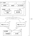
図1は、本発明の第1の実施形態における設定適用システム10の構成を示すブロック図である。
<First Embodiment>
FIG. 1 is a block diagram showing a configuration of a
図1において、設定適用システム10は、通信装置1、通信装置2及びサーバ装置3を有する。これら通信装置1及び通信装置2とサーバ装置3とは、通信ネットワーク110を介して通信可能に接続する。
In FIG. 1, the
尚、以下の説明では、説明の便宜上、第1の通信装置を「通信装置1」と称し、第2の通信装置を「通信装置2」と称する。また、以下の説明では、通信装置1及び通信装置2を、総称して「通信装置」と称する(以下、各実施形態においても同様)。
In the following description, for convenience of explanation, the first communication device is referred to as “
より具体的に、図1において、通信装置(通信装置1及び通信装置2)は、管理部4を備える。
More specifically, in FIG. 1, the communication devices (
管理部4は、バックアップの対象である特定の通信装置(第1通信装置)の設定情報(第1の設定情報102)を格納部6(第2格納部)に保持する。また、管理部4は、後述する制御部7から第2の設定情報104を得た場合には、その第2の設定情報104を格納部6に保持するよう制御する。
The
より具体的に、管理部4は、バックアップの対象である特定の通信装置の第1の設定情報102をバックアップする場合に、第1の設定情報102を適用すべき通信装置を識別可能な識別情報101と、格納部6に格納された第1の設定情報102とを含むバックアップ情報103を、通信部5を介してサーバ装置3に対して与える。
More specifically, when the
ここで、識別情報101は、例えば、自装置と異なる他の通信装置を識別可能な情報である。即ち、識別情報101は、第1の設定情報102を適用すべき通信装置を識別可能な情報である。より具体的に、識別情報101は、例えば、当該他の通信装置のMACアドレスである。
Here, the
また、第1の設定情報102とは、バックアップの対象である通信装置に設定された各種情報を含む。より具体的に、一例として、第1の設定情報102は、自装置の機種名(本願では、「装置名」とも記す)、SSID、暗号化キー、PPPoEの認証ID及び認証パスワード、MACアドレスフィルタリングに関する情報及びパケットフィルタリングに関する情報などを含む。但し、第1の設定情報102は、上述した情報だけでなく、通信装置に設定可能な機能に関する情報を含む。
The
ここで、より具体的に、一例として、MACアドレスフィルタリングに関する情報は、例えば、フィルタリングの対象である特定のMACアドレスを示す情報などを含む。また、パケットフィルタリングに関する情報は、フィルタリングの対象である送信元または送信先のIPアドレスを示す情報などを含む。但し、本実施形態を例に説明する本発明は、前述した構成には限定されない(以下、各実施形態においても同様)。 Here, more specifically, as an example, the information regarding MAC address filtering includes, for example, information indicating a specific MAC address to be filtered. The information related to packet filtering includes information indicating the IP address of the transmission source or the transmission destination that is the object of filtering. However, the present invention described using this embodiment as an example is not limited to the configuration described above (hereinafter, the same applies to each embodiment).
尚、以下の説明では、説明の便宜上、第1の設定情報102に含まれる機種名を、「第1の機種名」と称する。即ち、以下の説明では、バックアップの対象である通信装置の機種名を「第1の機種名」と称する。また、以下の説明では、第1の設定情報102を適用すべき通信装置の機種名を示す情報を「機種名情報」と称する(以下、各実施形態においても同様)。
In the following description, for convenience of description, the model name included in the
次に、管理部4は、第1の設定情報102を適用する場合には、第1の設定情報102を適用すべき通信装置を識別可能な識別情報101と、当該通信装置の機種名を示す情報(機種名情報)とを、通信部5を介してサーバ装置3に対して与える。
Next, when applying the
そして、管理部4は、サーバ装置3から設定情報(第2の設定情報104)を受信した場合には、その第2の設定情報104を格納部6に保持する。即ち、管理部4は、既に、格納部6に設定情報が格納されている場合に、受信した第2の設定情報104によって、当該設定情報を更新(例えば、上書き)する。
When the
尚、説明をよりわかりやすくすることを目的として、図1に示す通信装置2の格納部6は、設定情報を備えない構成を例に説明する。しかしながら、本発明に係る実施形態は、係る構成に限定されない。通信装置2の格納部6は、設定情報を備える構成を採用してもよい(以下、各実施形態においても同様)。
For the purpose of making the explanation easier to understand, the
これにより、通信装置は、第2の設定情報104に基づき自装置の設定を更新することができる。
Thereby, the communication apparatus can update the setting of the own apparatus based on the
より具体的に、例えば、通信装置1の設定情報(第1の設定情報102)を通信装置2に適用する場合に、通信装置1は、識別情報101と第1の設定情報102とを含むバックアップ情報103を、サーバ装置3にバックアップする。また、通信装置2は、自装置の識別情報101と機種名情報とをサーバ装置3に対して送信する。そして、通信装置2は、識別情報101と機種名情報とを送信するのに応じて、サーバ装置3から得た第2の設定情報104を格納部6に保持する。これにより、通信装置2は、バックアップした通信装置1の設定情報を、自装置に適用することができる。
More specifically, for example, when the setting information (first setting information 102) of the
次に、格納部6は、通信装置に設定された情報(第1の設定情報102)を含む各種情報を保持する。また、格納部6は、通信装置によるデータの読み書きが可能な不揮発性の記憶デバイスである。
Next, the
より具体的に、一例として、格納部6は、通信装置に搭載されたストレージデバイス等の不揮発性の記憶装置を採用することができる。
More specifically, as an example, the
通信ネットワーク110は、例えば、携帯電話事業者が所有する各種通信回線、インターネットサービスプロバイダ等が提供するインターネット等の一般的な通信回線やホームゲートウェイ等により構成された家庭内のネットワークである。
The
次に、サーバ装置3は、制御部7を備える。
Next, the server device 3 includes a
より具体的に、制御部7は、通信装置から識別情報101と第1の設定情報102とを含むバックアップ情報103を受信した場合に、そのバックアップ情報103を、格納部(第1格納部)9に格納するよう制御する。また、制御部7は、通信部8を介してバックアップ情報103の格納が成功したことを示す情報を、当該通信装置に対して与える。
More specifically, when the
ここで、バックアップ情報103は、識別情報101と第1の設定情報102とが関連付けられた情報である。
Here, the
尚、制御部7は、例えば、所定の期間に亘って、バックアップ情報103を、格納部9に格納する構成を採用してもよい。即ち、制御部7は、一時的に、バックアップ情報103を、格納部9に格納する構成を採用してもよい。また、制御部7は、所定の期間が経過した際には、バックアップ情報103を、格納部9から削除する構成を採用してもよい。これにより、制御部7は、より速やかにバックアップ情報103の中から識別情報101に関連付けられた第1の設定情報102を求めることができる。
For example, the
次に、制御部7は、通信部8を介して通信装置から識別情報101と機種名情報とを受信した場合には、受信した識別情報101に基づいて格納部9に格納されたバックアップ情報103を参照する。制御部7は、バックアップ情報103を参照した結果、バックアップ情報103の中から識別情報101に関連付けられた第1の設定情報102を求める。
Next, when receiving the
制御部7は、求めた第1の設定情報102と受信した機種名情報とに基づいて、変換処理を実行することによって、第1の設定情報102を、機種名情報が示す通信装置に適用可能なデータファイルの構成に変換することにより第2の設定情報104を生成する。そして、制御部7は、第2の設定情報104を、当該通信装置に対して与える。
The
より具体的に、制御部7は、求めた第1の設定情報102に含まれる第1の機種名と機種名情報とに基づいて、機種名毎に、格納部9に格納されたデータファイルの構成変換に必要となる情報を抽出する。制御部7は、抽出した情報に従い、第1の設定情報102におけるデータファイルの構成を、機種名情報が示す通信装置において適用可能な構成(形式)に変換する。即ち、制御部7は、適用先である通信装置に応じて、第1の設定情報102におけるデータファイルの構成を変換することにより第2の設定情報104を生成する。そして、制御部7は、第2の設定情報104を、当該通信装置に対して与える。
More specifically, the
ここで、係る構成変換に必要となる情報とは、例えば、機種Aから機種Bに適用可能なように構成を変換する処理、機種Aから機種Cに適用可能なように構成を変換する処理及び機種Dから機種Bに適用可能なように構成を変換する処理を示す情報を含む。即ち、当該構成変換に必要となる情報は、変換前の機種と変換後の機種毎に構成の変換に必要となる処理を示す情報を含む。 Here, the information necessary for the configuration conversion includes, for example, a process of converting the configuration so as to be applicable from the model A to the model B, a process of converting the configuration so as to be applicable from the model A to the model C, and It includes information indicating a process of converting the configuration so that the model D can be applied to the model B. That is, the information necessary for the configuration conversion includes information indicating processing necessary for configuration conversion for each model before conversion and for each model after conversion.
通信部5及び通信部8は、例えば、WAN(Wide_Area_Network)インタフェースを有する。また、通信部5及び通信部8は、通信ネットワーク110を介して相互に通信可能なようにサーバ装置3と通信装置とを接続する。
The
格納部9は、バックアップ情報103を保持する。格納部9は、コンピュータによるデータの読み書きが可能な不揮発性の記憶デバイスである。より具体的に、一例として、格納部9は、情報処理装置等の電子機器に搭載されたハードディスクドライブ(Hard_disk_drive:以降、「HDD」と称する)等の不揮発性の記憶装置を採用することができる。
The
また、一例として、格納部9は、通信ネットワーク110に接続されたストレージデバイス(不図示)を採用してもよい。但し、本実施形態を例に説明する本発明は、前述した構成には限定されない(以下の実施形態においても同様)。
For example, the
尚、上述した本実施形態では、説明の便宜上、一例として、制御部7は、サーバ装置3が備える構成を例に説明した。しかしながら本発明に係る実施形態は、係る構成に限定されない。制御部7は、例えば、通信装置が備える構成を採用してもよい。
In the embodiment described above, for the sake of convenience of explanation, the
その場合に、例えば、制御部7は、識別情報101に基づいて、サーバ装置3に格納されたバックアップ情報103を参照する。制御部7は、バックアップ情報103を参照した結果、バックアップ情報103の中から識別情報101に関連付けられた第1の設定情報102を求める。次に、制御部7は、求めた第1の設定情報102と自装置の機種名(機種名情報)とに基づいて、変換処理を実行する構成を採用してもよい。
In this case, for example, the
また、上述した本実施形態では、説明の便宜上、一例として、設定適用システム10は、特定の通信装置における設定情報を、係る他の通信装置に適用する構成を例に説明した。しかしながら本発明に係る実施形態は、係る構成に限定されない。設定適用システム10は、特定の通信装置の設定情報を、自装置に適用する構成を採用してもよい。即ち、設定適用システム10は、設定情報のバックアップに用いることも可能である。
Further, in the present embodiment described above, for the sake of convenience of explanation, as an example, the
このように本実施の形態に係る設定適用システム10によれば、煩わしい操作を必要とすることなく、特定の装置に設定された情報を所望の装置に適用することができる。その理由は、以下に述べる通りである。
As described above, according to the
即ち、設定適用システム10は、通信装置の設定情報をバックアップ、または適用可能な管理部4と、当該設定情報を適用すべき通信装置に適用可能なデータファイルの構成に変換する制御部7とを備えるからである。これにより、例えば、特定の通信装置を、その特定の通信装置と異なる他の通信装置に置き換えた際に、利用者は、特定の通信装置の設定情報を、当該の他通信装置に対して容易に適用することができる。また、SSID、暗号化キー、PPPoEの認証ID及び認証パスワードなどを含む設定情報を当該の他通信装置に対して適用することができるため、利用者は、端末装置においてSSIDなどの設定作業が不要となる。即ち、利用者の利便性は向上する。
That is, the
また、特定の通信装置と係る他の通信装置とを製造するメーカや機種が異なる場合であっても、設定適用システム10は、特定の通信装置の設定情報を、当該他の通信装置に適用することができる。その理由は、制御部7は、特定の通信装置の設定情報を、当該他の通信装置に適用可能なようにデータファイルの構成を変換することができるからである。
Even if the manufacturer and model of the specific communication device and the other communication device are different, the
<第2の実施形態>
次に、上述した本発明の第1の実施形態に係る設定適用システム10を基本とする第2の実施形態について説明する。以下の説明においては、本実施形態に係る特徴的な部分を中心に説明する。その際、上述した各実施形態と同様な構成については、同一の参照番号を付すことにより、重複する説明は省略する。
<Second Embodiment>
Next, a second embodiment based on the
本発明の第2の実施形態における設定適用システム20について、図2乃至図4を参照して説明する。
A
図2は、本発明の第2の実施形態における設定適用システム20の構成を示すブロック図である。
FIG. 2 is a block diagram showing the configuration of the
図2において、設定適用システム20は、通信装置1、通信装置2及びサーバ装置21を有する。
In FIG. 2, the
本実施形態において、設定適用システム20は、通信装置間における機能の差分を抽出すると共に、その差分に関する情報を提示する差分抽出部22を、さらに有する点が第1の実施形態において説明した設定適用システム10と異なる。
In the present embodiment, the
より具体的に、差分抽出部22は、制御部7によって求められた第1の設定情報102に含まれる第1の機種名と、通信装置から得た機種名情報が示す機種名とに基づいて、それぞれの通信装置が有する機能の差分を抽出する。即ち、差分抽出部22は、予め格納部9に格納された機能情報105の中から第1の機種名と機種名情報が示す機種名とに関連付けられた機能に関する情報を抽出する。
More specifically, the
ここで、機能情報105は、機種名毎に、その機種名に関連付けされた機能と、その機能に関する情報とを含む。
Here, the
次に、差分抽出部22は、抽出した機能差分に関する情報を含む差分情報を、例えば、通信装置に対して与える。即ち、差分抽出部22は、抽出した機能のうち差分のある機能に関する情報を含む差分情報を、例えば、通信装置に対して与える。
Next, the
例えば、差分抽出部22は、差分情報を、利用者が容易に識別可能な態様によって提示する構成を採用してもよい。より具体的に、差分抽出部22は、例えば、抽出した情報に基づき機能の名称(機能名)と、その機能について記載されたWebページのURL(Uniform_Resource_Locator)とを含む差分情報を提示する構成を採用してもよい。尚、本願では、Webページを、単に「ページ」と記す(以下、各実施形態においても同様)。
For example, the
また、一例として、通信装置は、差分抽出部22から得た差分情報を、不図示の端末装置(例えば、図5に示す端末装置33)に表示(提示)する構成を採用してもよい。或いは、差分抽出部22は、差分情報を、電子メールを利用して端末装置に対して配信(提示)する構成を採用してもよい。但し、本実施形態を例に説明する本発明は、前述した構成には限定されない(以下、各実施形態においても同様)。
As an example, the communication device may adopt a configuration in which the difference information obtained from the
このように、例えば、利用者は、提示された差分情報を参照することによって、2つの通信装置の機能差分とその機能の詳細内容を確認することができる。設定適用システム20は、利用者の利便性を高めることができる。
Thus, for example, the user can confirm the functional difference between the two communication devices and the detailed content of the function by referring to the presented difference information. The
次に、以下の説明では、より具体的に、本実施形態における設定適用システム20が行う動作について説明する。まず、以下の説明では、本実施形態における設定適用システム20が行うバックアップ処理の動作について説明する。
Next, in the following description, operations performed by the
図3は、本発明の第2の実施形態における設定適用システム20が行うバックアップ処理の動作を示すフローチャートである。係るフローチャートに沿って設定適用システム20の動作手順を説明する。
FIG. 3 is a flowchart showing the operation of the backup process performed by the
ここでは、説明の便宜上、一例として、設定適用システム20は、通信装置1の設定情報をバックアップすることとする。
Here, for convenience of explanation, as an example, the
尚、以下の説明では、説明の便宜上、通信装置1が有する管理部4を管理部A、通信部5を通信部A及び格納部6を格納部Aと称する。また、通信装置2が有する管理部4を管理部B、通信部5を通信部B及び格納部6を格納部Bと称する。
In the following description, for convenience of explanation, the
また、説明の便宜上、上述した構成を例に説明するが、本実施形態を例に説明する本発明は、前述した構成にはこれに限定されない(以下の実施形態においても同様)。 For convenience of explanation, the above-described configuration will be described as an example. However, the present invention described using this embodiment as an example is not limited to the above-described configuration (the same applies to the following embodiments).
(バックアップ処理)
ステップS1:
管理部Aは、識別情報101が入力されるのに応じて、識別情報101と格納部Aに保持された設定情報(第1の設定情報102)とを含むバックアップ情報103を、通信部Aを介してサーバ装置3に対して送信する。
(Backup process)
Step S1:
In response to the input of the
ここでは、識別情報101は、通信装置2のMACアドレスである。
Here, the
ステップS2:
制御部7は、通信装置1から識別情報101と第1の設定情報102とを含むバックアップ情報103を受信すると共に、受信したバックアップ情報103を格納部9に格納するよう制御する。
Step S2:
The
ステップS3:
制御部7は、通信部8を介してバックアップ情報103の格納が成功したことを示す情報を、通信装置1に対して送信する。即ち、制御部7は、当該格納に成功したことを、バックアップ情報103を送信した通信装置1に対して通知する。
Step S3:
The
一例として、通信装置1は、係る成功したことを示す情報を、例えば、不図示の端末装置に提示する構成を採用してもよい。或いは、通信装置1は、係る成功したことを示す情報を、例えば、自装置が有するLED(Light_Emitting_Diode)を点灯することによって提示する構成を採用してもよい。即ち、通信装置1は、係る成功したことを示す情報を、利用者が容易に識別可能な態様によって提示する構成を採用することができる。これにより、利用者は、容易に通信装置1における設定情報のバックアップが完了したことを認識すると共に、通信装置1の電源を切ることができる。
As an example, the
(適用処理)
次に、以下の説明では、より具体的に、本実施形態における設定適用システム20が行う設定情報を適用する処理の動作について説明する。
(Apply processing)
Next, in the following description, the operation of the process for applying the setting information performed by the
図4は、本発明の第2の実施形態における設定適用システム20が行う設定情報を適用する処理の動作を示すフローチャートである。係るフローチャートに沿って設定適用システム20の動作手順を説明する。
FIG. 4 is a flowchart showing an operation of processing for applying setting information performed by the
ここでは、説明の便宜上、一例として、設定適用システム20は、通信装置1の設定情報を、通信装置2に適用することとする。即ち、通信装置1は、通信装置2に置き換えられることとする。
Here, for convenience of explanation, as an example, the
ステップS11:
管理部Bは、自装置を識別可能な識別情報101と、自装置の機種名を示す情報(機種名情報)とを、通信部Bを介してサーバ装置3に対して送信する。
Step S11:
The management unit B transmits
ステップS12:
制御部7は、通信装置2から識別情報101と機種名情報とを受信するのに応じて、受信した識別情報101に基づき格納部9に格納されたバックアップ情報103を参照する。そして、制御部7は、バックアップ情報103の中から識別情報101に関連付けられた第1の設定情報102を求める。
Step S12:
In response to receiving the
より具体的に、制御部7は、バックアップ情報103を参照すると共に、識別情報101と一致する識別情報の有無を判別する。
More specifically, the
ステップS12において「YES」:
制御部7は、判別した結果、バックアップ情報103に識別情報101と一致する識別情報が有ると判別した場合に、処理をステップS14に進める。
“YES” in step S12:
As a result of the determination, when it is determined that the
ステップS12において「NO」:
制御部7は、判別した結果、バックアップ情報103に識別情報101と一致する識別情報が無いと判別した場合に、処理をステップS13に進める。
“NO” in step S12:
As a result of the determination, when it is determined that there is no identification information that matches the
ステップS13:
制御部7は、識別情報101と一致する識別情報が無いことを示す情報を、通信装置2に対して送信する。そして、制御部7は、処理を終了する。
Step S13:
The
ステップS14:
制御部7は、バックアップ情報103の中から識別情報101に関連付けられた第1の設定情報102を求める。即ち、制御部7は、バックアップ情報103の中から識別情報101に関連付けられた第1の設定情報102を抽出する。
Step S14:
The
ステップS15:
差分抽出部22は、制御部7によって求められた第1の設定情報102に含まれる第1の機種名と、通信装置2から得た機種名情報が示す機種名とに基づいて、それぞれの通信装置が有する機能差分の有無を判別する。
Step S15:
The
ステップS15において「YES」:
差分抽出部22は、機能差分の有無を判別した結果、第1の機種名を有する通信装置と機種名情報が示す機種名との間において機能差分が有ると判別した場合に、処理をステップS16に進める。
“YES” in step S15:
If the
ステップS15において「NO」:
差分抽出部22は、機能差分の有無を判別した結果、第1の機種名を有する通信装置と機種名情報が示す機種名との間において機能差分が無いと判別した場合に、処理をステップS17に進める。
“NO” in step S15:
If the
ステップS16:
差分抽出部22は、制御部7によって求められた第1の設定情報102に含まれる第1の機種名と、通信装置2から得た機種名情報が示す機種名とに基づいて、それぞれの通信装置が有する機能の差分を抽出する。また、差分抽出部22は、抽出した機能差分に関する情報を含む差分情報を、通信装置2に対して送信すると共に、処理をステップS18に進める。
Step S16:
The
ステップS17:
差分抽出部22は、通信装置間において機能差分が無いことを示す情報を含む差分情報を、通信装置2に対して送信すると共に、処理をステップS18に進める。
Step S17:
The
ステップS18:
制御部7は、求めた第1の設定情報102と受信した機種名情報とに基づいて、変換処理を実行することによって、第1の設定情報102を、機種名情報が示す通信装置に適用可能なデータファイルの構成に変換する。即ち、第1の設定情報102と受信した機種名情報とに基づいて、変換処理を実行することによって、第2の設定情報104を生成する。制御部7は、第2の設定情報104を通信装置2に対して送信する。
Step S18:
The
ステップS19:
管理部Bは、サーバ装置21から第2の設定情報104と差分情報とを受信する。管理部Bは、受信した第2の設定情報104と差分情報とを、格納部Bに保持するよう制御する。
Step S19:
The management unit B receives the
これにより、通信装置2は、通信装置1の設定情報(第1の設定情報102)に基づき生成された第2の設定情報104に基づいて、自装置の設定を更新することができる。また、通信装置2は、係る機能差分が無いことを示す情報、または機能差分に関する情報を、例えば、不図示の端末装置に提示する構成を採用してもよい。
Thereby, the
尚、図3及び図4において説明した処理は、後述する図7、図8A、図8B及び図12のシーケンス図に示す処理に、同一の参照番号を付すことによって含む。 Note that the processing described in FIGS. 3 and 4 is included by attaching the same reference numerals to the processing shown in the sequence diagrams of FIGS. 7, 8A, 8B, and 12 described later.
このように本実施の形態に係る設定適用システム20によれば、第1の実施形態において説明した効果を享受できると共に、さらに、利用者の利便性を高めることができる。
Thus, according to the
その理由は、設定適用システム20は、バックアップの対象である通信装置と、バックアップされた設定情報が適用される通信装置との機能差分を抽出すると共に、その機能差分を示す情報を提示する差分抽出部22を、さらに備えるからである。
The reason is that the
<第3の実施形態>
次に、上述した本発明の第2の実施形態に係る設定適用システム20を基本とする第3の実施形態について説明する。以下の説明においては、本実施形態に係る特徴的な部分を中心に説明する。その際、上述した各実施形態と同様な構成については、同一の参照番号を付すことにより、重複する説明は省略する。
<Third Embodiment>
Next, a third embodiment based on the
本発明の第3の実施形態における設定適用システム30について、図3乃至図8(図8A及び図8B)を参照して説明する。
A
図5は、本発明の第3の実施形態における設定適用システム30の構成を示すブロック図である。
FIG. 5 is a block diagram showing the configuration of the
図5において、設定適用システム30は、無線LANルータ31、無線LANルータ32及びサーバ装置21を有する。
In FIG. 5, the
尚、以下の説明では、説明の便宜上、第1の無線LANルータを「無線LANルータ31」と称し、第2の無線LANルータを「無線LANルータ32」と称する。また、以下の説明では、無線LANルータ31及び無線LANルータ32を、総称して「無線LANルータ」と称する(以下、各実施形態においても同様)。
In the following description, for convenience of explanation, the first wireless LAN router is referred to as “
無線LANルータ31は、第1及び第2の実施形態において説明した通信装置1に相当する。また、無線LANルータ32は、第1及び第2の実施形態において説明した通信装置2に相当する。
The
無線LANルータ31及び無線LANルータ32は、WebGUI部(インタフェース部)34、スイッチ部(操作部)35及び通信確立部39を、さらに有する点が第2の実施形態において説明した通信装置1及び通信装置2と異なる。
The
図6は、本発明の第3の実施形態における無線LANルータ31の構成を示すブロック図である。尚、説明の便宜上、図6には、無線LANルータ31の構成を示すが無線LANルータ32の構成も同様である。そのため、無線LANルータ32の構成を示すブロック図は、同一の参照番号を付すことにより省略する。
FIG. 6 is a block diagram showing the configuration of the
図6において、無線LANルータ31は、WebGUI部34及びスイッチ部35を、さらに有する。また、格納部6は、さらに認証情報106を保持する。
In FIG. 6, the
WebGUI部34は、無線LANルータ31または無線LANルータ32の設定に要する操作をユーザに提供可能なインタフェースを提供する。即ち、WebGUI部34は、無線LANルータにおける設定情報(第1の設定情報102)のバックアップ及び第2の設定情報104の適用に要する操作を容易に実行可能なインタフェースを提供する。
The
スイッチ部35は、例えば、利用者に操作(例えば、押下)されることによって、無線LANルータに対して適用処理を開始するよう指示する。即ち、スイッチ部35は、適用処理を開始するトリガーである。言い換えると、スイッチ部35は、管理部4に対して設定情報を適用する処理を開始するよう制御する。
For example, the
認証情報106は、PPPoEの認証IDと認証パスワードを含む。より具体的に、認証情報106は、サーバ装置21との接続に際して用いるPPPoEの認証IDと認証パスワードを含む。即ち、認証情報106は、仮のPPPoEの認証IDと認証パスワードを含む。例えば、認証情報106は、工場出荷時に格納部6に格納される構成を採用してもよい。
The
通信確立部39は、通信装置に対して格納部6に格納された認証情報106を用いて自装置と異なる他の装置と通信可能に接続するよう制御する。即ち、係る適用処理を実行する場合には、通信確立部39は、通信装置に対して認証情報106を用いてサーバ装置21と通信可能に接続するよう制御する。
The
このため、利用者は、PPPoEの認証IDと認証パスワードを設定することなく、サーバ装置21に接続することができる。また、無線LANルータは、第2の設定情報104を適用後には、第2の設定情報104に含まれるPPPoEの認証IDと認証パスワードを用いて通信ネットワーク110に接続することができる。
Therefore, the user can connect to the
端末装置33は、無線通信部37及び表示部38を有する。
The
無線通信部36及び無線通信部37は、無線LANインタフェースを有する。そのため、無線LANルータと端末装置33とは、それぞれが有する無線通信部36と無線通信部37とを介して通信可能に接続する。
The
表示部38は、例えば、ディスプレイ等のユーザインタフェースを介してページなどの各種コンテンツを利用者に提示する。
The
以下の説明において、より具体的に、本実施形態における設定適用システム30の動作について説明する。
In the following description, the operation of the
図7は、本発明の第3の実施形態における設定適用システム30が行うバックアップ処理の動作を示すシーケンス図(フローチャート)である。図8A及び図8Bは、本発明の第3の実施形態における設定適用システム30が行う設定情報を適用する処理の動作を示すシーケンス図(フローチャート)である。係るシーケンス図に沿って設定適用システム30の動作手順を説明する。その際、図3及び図4に示すフローチャートにおいて説明した構成については、同一の参照番号を付すことにより、重複する説明は省略する。
FIG. 7 is a sequence diagram (flow chart) showing the operation of the backup process performed by the
以下の説明では、説明の便宜上、一例として、無線LANルータ31の設定情報をバックアップすることとする。また、以下の説明では、バックアップされた設定情報は、無線LANルータ32に適用されることとする。
In the following description, for convenience of explanation, the setting information of the
尚、以下の説明では、説明の便宜上、無線LANルータ31が有する管理部4を管理部A、通信部5を通信部A、格納部6を格納部A、WebGUI部34を、をWebGUI部A、スイッチ部35をスイッチ部A及び無線通信部36を無線通信部Aと称する。また、無線LANルータ32が有する管理部4を管理部B、通信部5を通信部B、格納部6を格納部B、WebGUI部34をWebGUI部B、スイッチ部35をスイッチ部B及び無線通信部36を無線通信部Bと称する。
In the following description, for convenience of explanation, the
尚、説明の便宜上、上述した構成を例に説明するが、本実施形態を例に説明する本発明は、前述した構成にはこれに限定されない(以下の実施形態においても同様)。 For convenience of explanation, the above-described configuration will be described as an example. However, the present invention described by taking this embodiment as an example is not limited to the above-described configuration (the same applies to the following embodiments).
(バックアップ処理)
ステップS21:
端末装置33は、利用者の操作に応じて、WebGUI部Aに対してMACアドレスの入力を促すページを表す情報を要求する。即ち、利用者は、端末装置33を用いてWebGUI部Aに格納されたMACアドレスの入力を促すページにアクセスする。
(Backup process)
Step S21:
The
ステップS22:
WebGUI部Aは、端末装置33からの要求に応じて、MACアドレスの入力を促すページを表す情報を、端末装置33に対して送信する。
Step S22:
In response to a request from the
ステップS23:
端末装置33は、MACアドレスの入力を促すページを表す情報を、無線通信部37を介して受信する。また、端末装置33は、受信した情報に基づき、表示部38に当該ページを表示する。
Step S23:
The
ここで、一例として、MACアドレスの入力を促すページは、MACアドレスを入力することが可能な入力フォームと、バックアップ処理を開始する実行ボタンとを含む。但し、本実施形態を例に説明する本発明は、前述した構成には限定されない(以下、各実施形態においても同様)。 Here, as an example, the page that prompts the input of the MAC address includes an input form in which the MAC address can be input and an execution button for starting the backup process. However, the present invention described using this embodiment as an example is not limited to the configuration described above (hereinafter, the same applies to each embodiment).
これにより、利用者は、バックアップした設定情報を適用する無線LANルータ32のMACアドレスを入力すると共に、バックアップ処理を開始することができる。
Accordingly, the user can input the MAC address of the
ステップS24:
端末装置33は、利用者の操作に応じて、無線LANルータ32のMACアドレスを示す識別情報101を、WebGUI部Aに対して送信する。
Step S24:
The
例えば、入力フォームにMACアドレスが入力されていない場合には、端末装置33は、エラーを示す情報を表示部38に表示する。また、端末装置33は、MACアドレスの入力を促すページを表示部38に再表示する。即ち、端末装置33は、ステップS23に戻す構成を採用してもよい。
For example, when the MAC address is not input in the input form, the
ここでは、利用者は、表示部38に表示された入力フォームにMACアドレスを入力すると共に、実行ボタンを押下することとする。
Here, it is assumed that the user inputs the MAC address in the input form displayed on the
ステップS25:
WebGUI部Aは、端末装置33から識別情報101を受信すると共に、受信した識別情報101を管理部Aに対して送信する。
Step S25:
The Web GUI unit A receives the
ステップS1:
管理部Aは、WebGUI部Aから識別情報101を受信するのに応じて、識別情報101と格納部Aに格納された第1の設定情報102とを含むバックアップ情報103を、通信部Aを介してサーバ装置21に対して送信する。
Step S1:
In response to receiving the
ステップS2:
制御部7は、無線LANルータ31からバックアップ情報103を受信すると共に、受信したバックアップ情報103を格納部9に格納する。
Step S2:
The
ステップS3:
制御部7は、通信部8を介してバックアップ情報103の格納が成功したことを示す情報を、無線LANルータ31に対して送信する。
Step S3:
The
ステップS26:
無線LANルータ31は、サーバ装置21から係る成功したことを示す情報を受信する。また、WebGUI部Aは、バックアップ情報103の格納が成功したことを示す情報と、無線LANルータ32に置き換えるよう指示を示す情報とを端末装置33に対して送信する。
Step S26:
The
ステップS27:
端末装置33は、WebGUI部Aから格納が成功したことを示す情報と、無線LANルータ32に置き換えるよう指示を示す情報とを受信すると共に、受信したそれら情報を表示部38に表示する。
Step S27:
The
これにより、利用者は、無線LANルータ31における設定情報のバッアップが成功したことを認識することができる。また、利用者は、無線LANルータ31の電源を切ると共に、無線LANルータ32に置き換えることができる。
Thereby, the user can recognize that the backup of the setting information in the
(適用処理)
ステップS28:
無線LANルータ32は、スイッチ部Bが利用者に押下されるのに応じて、接続処理を開始する。
(Apply processing)
Step S28:
The
例えば、無線LANルータ32は、通信ネットワーク110に接続可能か否かを判別する。無線LANルータ32は、通信ネットワーク110に接続可能であると判別した場合に、サーバ装置21と接続を確立する。
For example, the
一方で、無線LANルータ32は、通信ネットワーク110に接続できないと判別した場合には、PPPoE認証が必要か否かを判別する。無線LANルータ32は、PPPoE認証が必要でないと判別した場合に、WebGUI部Bを用いて接続エラーを示す情報を端末装置33に対して送信する。端末装置33は、WebGUI部Bから当該接続エラーを示す情報を受信すると共に、その情報を表示部38に表示する。次に、PPPoE認証が必要であると判別した場合には、通信確立部39は、無線LANルータ32に対して格納部6に格納された認証情報106を用いて自装置と異なるサーバ装置21と通信可能に接続するよう制御する。無線LANルータ32は、格納部6に格納された認証情報106に含まれる認証IDとパスワードを用いてPPPoE認証を実施する。
On the other hand, when it is determined that the
尚、無線LANルータが通信ネットワーク110への接続可否及びPPPoE認証が必要か否かを判別する技術自体は、現在では一般的な技術を採用することができるので、本実施形態における詳細な説明は省略する(以下、各実施形態においても同様)。
The technology itself for determining whether or not the wireless LAN router can connect to the
ステップS11:
管理部Bは、自装置のMACアドレスを示す識別情報101と、自装置の機種名を示す情報(機種名情報)とを、通信部Bを介してサーバ装置21に対して送信する。
Step S11:
The management unit B transmits
ステップS12:
制御部7は、無線LANルータ32から識別情報101と機種名情報とを受信するのに応じて、受信した識別情報101に基づき格納部9に格納されたバックアップ情報103を参照する。また、制御部7は、識別情報101と一致する識別情報の有無を判別する。
Step S12:
In response to receiving the
ステップS12において「YES」:
制御部7は、判別した結果、バックアップ情報103に識別情報101と一致する識別情報が有ると判別した場合に、処理をステップS14に進める。
“YES” in step S12:
As a result of the determination, when it is determined that the
ステップS12において「NO」:
制御部7は、判別した結果、バックアップ情報103に識別情報101と一致する識別情報が無いと判別した場合に、処理をステップS13に進める。
“NO” in step S12:
As a result of the determination, when it is determined that there is no identification information that matches the
ステップS13:
制御部7は、識別情報101と一致する識別情報が無いことを示す情報を、無線LANルータ32に対して送信すると共に、処理をステップS29に進める。
Step S13:
The
ステップS14:
制御部7は、バックアップ情報103の中から識別情報101に関連付けられた第1の設定情報102を求める。
Step S14:
The
ステップS15:
差分抽出部22は、制御部7によって求められた第1の設定情報102に含まれる第1の機種名と、無線LANルータ32から得た機種名情報が示す機種名とに基づいて、それぞれの無線LANルータが有する機能差分の有無を判別する。
Step S15:
Based on the first model name included in the
ステップS15において「YES」:
差分抽出部22は、機能差分の有無を判別した結果、第1の機種名を有する通信装置と機種名情報が示す機種名との間において機能差分が有ると判別した場合に、処理をステップS16に進める。
“YES” in step S15:
If the
ステップS15において「NO」:
差分抽出部22は、機能差分の有無を判別した結果、第1の機種名を有する通信装置と機種名情報が示す機種名との間において機能差分が無いと判別した場合に、処理をステップS17に進める。
“NO” in step S15:
If the
ステップS16:
差分抽出部22は、制御部7によって求められた第1の設定情報102に含まれる第1の機種名と、無線LANルータ32から得た機種名情報が示す機種名とに基づいて、それぞれの無線LANルータが有する機能の差分を抽出する。また、差分抽出部22は、抽出した機能差分に関する情報を含む差分情報を、無線LANルータ32に対して送信すると共に、処理をステップS18に進める。
Step S16:
Based on the first model name included in the
ステップS17:
差分抽出部22は、無線LANルータ間において機能差分が無いことを示す情報を含む差分情報を、無線LANルータ32に対して送信すると共に、処理をステップS18に進める。
Step S17:
The
ステップS18:
制御部7は、第1の設定情報102と機種名情報とに基づいて、変換処理を実行することによって、第1の設定情報102を、機種名情報が示す無線LANルータに適用可能なデータファイルの構成に変換することにより第2の設定情報104を生成する。制御部7は、第2の設定情報104を、無線LANルータ32に対して送信する。
Step S18:
The
ステップS19:
管理部Bは、サーバ装置21から第2の設定情報104と差分情報とを受信する。管理部Bは、受信した第2の設定情報104と差分情報とを、格納部Bに保持すると共に、処理をステップS31に進める。
Step S19:
The management unit B receives the
ステップS29:
WebGUI部Bは、サーバ装置21から受信した係る一致する識別情報が無いことを示す情報に基づいて、エラーを示す情報を、端末装置33に対して送信する。
Step S29:
The Web GUI unit B transmits information indicating an error to the
ステップS30:
端末装置33は、WebGUI部Bから係るエラーを示す情報を受信すると共に、その情報を表示部38に表示する。
Step S30:
The
ステップS31:
WebGUI部Bは、サーバ装置21から受信した差分情報を、端末装置33に対して送信する。
Step S31:
The Web GUI unit B transmits the difference information received from the
ステップS32:
端末装置33は、WebGUI部Bから受信した差分情報を、表示部38に表示する。
Step S32:
The
このように本実施の形態に係る設定適用システム30によれば、各実施形態において説明した効果を享受できると共に、さらに、利用者の利便性を高めることができる。
Thus, according to the
その理由は、設定適用システム30は、無線LANルータの設定に要する操作をユーザに提供可能なインタフェースを提供するWebGUI部34と、適用処理を開始するトリガーであるスイッチ部35とを備えるからである。さらに、格納部6には、PPPoEの認証IDと認証パスワードを含む認証情報106を保持するからである。また、通信確立部39は、通信装置に対して格納部6に格納された認証情報106を用いて自装置と異なる他の装置と通信可能に接続するよう制御するからである。
The reason is that the
<第4の実施形態>
次に、上述した本発明の第3の実施形態に係る設定適用システム30を基本とする実施形態について説明する。以下の説明においては、本実施形態に係る特徴的な部分を中心に説明する。その際、上述した各実施形態と同様な構成については、同一の参照番号を付すことにより、重複する説明は省略する。
<Fourth Embodiment>
Next, an embodiment based on the
本発明の第4の実施形態における設定適用システム40について、図3、図4、図7、図9乃至図12を参照して説明する。
A
図9は、本発明の第4の実施形態における設定適用システム40の構成を示すブロック図である。
FIG. 9 is a block diagram showing the configuration of the
図9において、設定適用システム40は、無線LANルータ41、無線LANルータ42、サーバ装置21及び端末装置43を有する。
In FIG. 9, the
尚、以下の説明では、説明の便宜上、第1の無線LANルータを「無線LANルータ41」と称し、第2の無線LANルータを「無線LANルータ42」と称する。また、以下の説明では、無線LANルータ41及び無線LANルータ42を、総称して「無線LANルータ」と称する(以下、各実施形態においても同様)。
In the following description, for convenience of explanation, the first wireless LAN router is referred to as “
図10は、本発明の第4の実施形態における一方の無線LANルータ41の構成を示すブロック図である。また、図11は、本発明の第4の実施形態における他方の無線LANルータ42の構成を示すブロック図である。
FIG. 10 is a block diagram showing a configuration of one
図10において、無線LANルータ41は、QR(Quick_Response)コード(登録商標)44を、さらに備える。また、図11において、無線LANルータ42は、QRコード45を、さらに備える。
In FIG. 10, the
QRコード44は、無線LANルータ41のMACアドレスを示す二次元コードである。また、QRコード45は、無線LANルータ42のMACアドレスを示す二次元コードである。
The
図9において、端末装置43は、カメラ(撮像部)46及びカメラ制御部(撮像制御部)47を備える。
In FIG. 9, the
カメラ46は、例えば、静止画像及び動画像を撮像可能なカメラ装置である。カメラ制御部47は、カメラ46を制御する機能を備える。より具体的に、カメラ制御部47は、カメラ46の有無を判別する。即ち、カメラ制御部47は、端末装置43(自装置)がカメラ46を搭載しているか否かを判別する。カメラ制御部47は、カメラ46の有無を判別した結果、カメラ46が搭載されていると判別した場合に、カメラ46に対して動作を開始するよう制御すると共に、QRコード(QRコード44及びQRコード45)の読み込み画面を表示部38に表示する。
The
これにより、カメラ46は、利用者の操作に応じて、QRコードを読み込むことができる。また、カメラ制御部47は、QRコードに含まれるMACアドレスを取得することができる。
Thereby, the
一方で、カメラ制御部47は、カメラ46の有無を判別した結果、カメラ46が搭載されていないと判別した場合に、MACアドレスの入力を促す画面を表示部38に表示する。
On the other hand, when the
これにより、カメラ制御部47は、端末装置43がカメラ46を搭載していない場合であっても、MACアドレスを取得することができる。
Thereby, the
このように、第3の実施形態では、図7のステップS23に示すように、MACアドレスを入力可能な入力フォームにMACアドレスを入力する構成を採用した。しかしながら、本実施形態では、端末装置43が備えるカメラ46によって、QRコード45を読み込むことができる。これにより、設定適用システム40は、利用者のMACアドレスの入力に要する作業工数を軽減することができるだけでなく、入力ミスを防ぐことができる。
As described above, in the third embodiment, as shown in step S23 of FIG. 7, a configuration is adopted in which the MAC address is input to the input form in which the MAC address can be input. However, in the present embodiment, the
尚、図面に示した端末装置43を構成するカメラ制御部47は、ハードウェアまたはソフトウェアモジュールとして実現することができる。即ち、カメラ制御部47は、ソフトウェアプログラムの機能(処理)単位と捉えることができる。
In addition, the
次に、以下の説明において、より具体的に、本実施形態における設定適用システム40の動作について説明する。
Next, in the following description, the operation of the
図12は、本発明の第4の実施形態における設定適用システム40が行うバックアップ処理の動作を示すシーケンス図(フローチャート)である。係るシーケンス図に沿って設定適用システム40の動作手順を説明する。その際、図3に示すフローチャート、図7に示すシーケンス図において説明した構成については、同一の参照番号を付すことにより、重複する説明は省略する。
FIG. 12 is a sequence diagram (flow chart) showing the operation of the backup process performed by the
以下の説明では、説明の便宜上、一例として、無線LANルータ41の設定情報をバックアップすることとする。また、以下の説明では、バックアップされた設定情報は、無線LANルータ42に適用されることとする。
In the following description, for convenience of explanation, setting information of the
尚、説明の便宜上、上述した構成を例に説明するが、本実施形態を例に説明する本発明は、前述した構成にはこれに限定されない(以下の実施形態においても同様)。 For convenience of explanation, the above-described configuration will be described as an example. However, the present invention described by taking this embodiment as an example is not limited to the above-described configuration (the same applies to the following embodiments).
以下の説明では、例えば、利用者は、端末装置43を操作することによりカメラ制御部47の機能を有するアプリケーションを実行する。
In the following description, for example, the user executes an application having the function of the
ここでは、無線LANルータ41と端末装置43とは、それぞれの無線通信部Aと無線通信部37とを介して通信可能に接続した状態である。
Here, the
ステップS41:
カメラ制御部47は、カメラ46の有無を判別する。
Step S41:
The
ステップS41において「YES」:
カメラ制御部47は、カメラ46の有無を判別した結果、カメラ46が有ると判別した場合に、処理をステップS42に進める。
"YES" in step S41:
The
ステップS41において「NO」:
カメラ制御部47は、カメラ46の有無を判別した結果、カメラ46が無いと判別した場合に、処理をステップS43に進める。
“NO” in step S41:
The
ステップS42:
カメラ制御部47は、QRコードを読み込み可能なように読み込み画面を表示部38に表示する。
Step S42:
The
ここでは、例えば、利用者は、端末装置43を操作することにより無線LANルータ42が備えるQRコード45を、カメラ46を用いて撮像することとする。
Here, for example, it is assumed that the user images the
ステップS43:
カメラ制御部47は、MACアドレスの入力を促す画面を表示部38に表示する。
Step S43:
The
一例として、MACアドレスの入力を促す画面は、MACアドレスを入力することが可能な入力フォームと、バックアップ処理を開始する実行ボタンとを含む。但し、本実施形態を例に説明する本発明は、前述した構成には限定されない(以下、各実施形態においても同様)。 As an example, the screen for prompting the input of the MAC address includes an input form in which the MAC address can be input and an execution button for starting the backup process. However, the present invention described using this embodiment as an example is not limited to the configuration described above (hereinafter, the same applies to each embodiment).
ここでは、例えば、利用者は、端末装置43を操作することにより無線LANルータ42のMACアドレスを入力することとする。
Here, for example, the user inputs the MAC address of the
ステップS44:
カメラ制御部47は、ステップS42においてQRコードを読み込むことにより得られるMACアドレス、またはステップS43において入力されたことにより得られるMACアドレスを取得する。また、カメラ制御部47は、得られたMACアドレスを示す情報を、識別情報101として無線LANルータ41に対して送信する。
Step S44:
The
以降、設定適用システム40は、図7に示すステップS25乃至ステップS27に示す処理を実行する。
Thereafter, the
尚、上述した本実施形態では、説明の便宜上、一例として、設定適用システム40は、得たMACアドレスを送信後に、図7に示すステップS25乃至ステップS27に示す処理を実行する構成を例に説明した。しかしながら本発明に係る実施形態は、係る構成に限定されない。設定適用システム40は、得たMACアドレスを送信後に、図3及び図4に示す処理を実行する構成を採用してもよい。即ち、設定適用システム40は、第1の実施形態において説明した設定適用システム10に適用して好適である。
In the above-described embodiment, for convenience of explanation, as an example, the
このように本実施の形態に係る設定適用システム40によれば、各実施形態において説明した効果を享受できると共に、さらに、利用者の利便性を高めることができる。
Thus, according to the
その理由は、設定適用システム40は、カメラ46を制御するカメラ制御部47を備えるからである。カメラ制御部47は、無線LANルータが備えるQRコードを読み込むよう制御することによって、無線LANルータのMACアドレスを取得することができる。これにより、設定適用システム40は、利用者のMACアドレスの入力に要する作業工数を軽減することができるだけでなく、入力ミスを防ぐことができるからである。
This is because the
(ハードウェア構成例)
上述した実施形態において図面に示した各部は、ソフトウェアプログラムの機能(処理)単位(ソフトウェアモジュール)と捉えることができる。これらの各ソフトウェアモジュールは、専用のハードウェアによって実現してもよい。但し、これらの図面に示した各部の区分けは、説明の便宜上の構成であり、実装に際しては、様々な構成が想定されうる。この場合のハードウェア環境の一例を、図13を参照して説明する。
(Hardware configuration example)
Each unit shown in the drawings in the embodiment described above can be regarded as a function (processing) unit (software module) of a software program. Each of these software modules may be realized by dedicated hardware. However, the division of each part shown in these drawings is a configuration for convenience of explanation, and various configurations can be assumed in mounting. An example of the hardware environment in this case will be described with reference to FIG.
図13は、本発明の模範的な実施形態に係る設定適用システムを構成する各部を実行可能な情報処理装置300(コンピュータ)の構成を例示的に説明する図である。即ち、図13は、サーバ等のコンピュータ(情報処理装置)の構成であって、上述した実施形態における各機能を実現可能なハードウェア環境を表す。このコンピュータは、設定適用システム10(図1)、或いは、設定適用システム20(図2)、設定適用システム30(図5)及び設定適用システム40(図9)、の全体または一部の設定適用システムを実現可能である。 FIG. 13 is a diagram exemplarily illustrating a configuration of an information processing apparatus 300 (computer) that can execute each unit included in the setting application system according to the exemplary embodiment of the present invention. That is, FIG. 13 shows a hardware environment that is a configuration of a computer (information processing apparatus) such as a server and that can realize each function in the above-described embodiment. This computer can be applied to all or part of the setting application system 10 (FIG. 1), or the setting application system 20 (FIG. 2), the setting application system 30 (FIG. 5), and the setting application system 40 (FIG. 9). The system can be realized.
図13に示した情報処理装置300は、以下の構成がバス306(通信線)を介して接続された一般的なコンピュータである。
An
・CPU(Central_Processing_Unit)301、
・ROM(Read_Only_Memory)302、
・RAM(Random_Access_Memory)303、
・ハードディスク304(記憶装置)、
・外部装置との通信インタフェース(Interface:以降、「I/F」と称する)305、
・CD−ROM(Compact_Disc_Read_Only_Memory)等の記憶媒体307に格納されたデータを読み書き可能なリーダライタ308。
CPU (Central_Processing_Unit) 301,
ROM (Read_Only_Memory) 302,
RAM (Random_Access_Memory) 303,
-Hard disk 304 (storage device),
A communication interface (Interface: hereinafter referred to as “I / F”) 305 with an external device
A reader /
そして、上述した実施形態を例に説明した本発明は、以下の手順によって達成される。即ち、図13に示した情報処理装置300に対して、その説明において参照したブロック構成図の図1に示す管理部4及び制御部7、図2に示す差分抽出部22、図6に示すWebGUI部(インタフェース部34)及び通信確立部39、図9に示すカメラ制御部47、或いはフローチャート(図3、図4、図7、図8A、図8B、図12)の機能を実現可能なコンピュータ・プログラムを供給される。その後、そのコンピュータ・プログラムは、当該ハードウェアのCPU301に読み出されて実行されることによって達成される。また、当該装置内に供給されたコンピュータ・プログラムは、読み書き可能な一時記憶メモリ(RAM303)またはハードディスク304等の不揮発性の記憶デバイスに格納すれば良い。
The present invention described using the above-described embodiment as an example is achieved by the following procedure. That is, for the
また、前記の場合において、当該ハードウェア内へのコンピュータ・プログラムの供給方法は、現在では一般的な手順を採用することができる。例えば、CD−ROM等の各種記憶媒体307を介して当該装置内にインストールする方法や、インターネット等の通信回線を介して外部よりダウンロードする方法等である。そして、このような場合において、本発明は、係るコンピュータ・プログラムを構成するコード、或いはそのコードが格納された記憶媒体によって構成されると捉えることができる。 In the above case, a general procedure can be adopted as a method for supplying a computer program into the hardware. For example, there are a method of installing in the apparatus via various storage media 307 such as a CD-ROM, and a method of downloading from the outside via a communication line such as the Internet. In such a case, it can be understood that the present invention is configured by a code constituting the computer program or a storage medium storing the code.
尚、上述した各実施形態の一部又は全部は、以下の付記のようにも記載されうる。しかしながら、上述した実施形態により例示的に説明した本発明は、以下には限らない。即ち、
(付記1)
バックアップ対象である第1通信装置の設定情報と、該設定情報を適用すべき第2通信装置を識別可能な識別情報とを関連付けて第1格納手段に格納するよう制御する制御手段と、
前記設定情報を保持し、前記変換手段から第2の設定情報を得た場合には、該第2の設定情報を第2格納手段に保持するよう制御する管理手段とを備え、
前記設定情報を前記第2通信装置に適用する場合に、前記制御手段は、
前記識別情報と前記第2通信装置の機種名を示す情報とに基づいて、該識別情報に関連付けられている前記設定情報を、前記第2通信装置に適用可能な構成に変換することによって前記第2の設定情報を生成する
ことを特徴とする設定適用システム。
(付記2)
前記変換手段は、
前記設定情報に含まれる前記特定の通信装置の機種名と前記機種名情報に含まれる前記第2通信装置の機種名とに基づいて、前記設定情報におけるデータファイルの構成を、前記第2通信装置において適用可能なデータファイルの構成に変換することにより前記第2の設定情報を生成する
ことを特徴とする付記1に記載の設定適用システム。
(付記3)
前記第1通信装置の機種名と前記種名情報に含まれる前記第2通信装置の機種名とに基づいて、機種名と通信装置が有する機能に関する情報とが関連付けられた機能情報を参照すると共に、その機能情報の中からそれぞれの通信装置が有する機能を抽出し、その抽出した機能のうち差分のある機能に関する情報を提示する差分抽出手段を、
さらに備えることを特徴とする付記1または付記2に記載の設定適用システム。
(付記4)
認証IDとパスワードとを含む認証情報を用いて自装置と異なる他の装置と通信可能に接続するよう制御する通信確立手段を、
さらに備えることを特徴とする付記1乃至付記3の何れかに記載の設定適用システム。
(付記5)
操作されるのに応じて、前記情報管理手段に対して前記設定情報を適用する処理を開始するよう制御する操作手段と、
前記設定情報のバックアップ及び前記第2の設定情報の適用に要する操作をユーザに提供可能なインタフェースを提供するインタフェース手段と、を
さらに備えることを特徴とする付記1乃至付記4の何れかに記載の設定適用システム。
(付記6)
自装置を識別可能な識別情報を含む二次元コードと、
前記二次元コードを読み取り可能な撮像手段と、
前記撮像手段を制御する撮像制御手段と、をさらに備え
前記撮像制御手段は、
前記撮像手段により前記二次元コードを読み込むことによって得た前記識別情報を前記管理手段に対して与える
ことを特徴とする付記1乃至付記5の何れかに記載の設定適用システム。
(付記7)
前記機能差分に関する情報は、
差分のある機能の名称とその機能について記載されたWebページのURLとを含むことを特徴とする付記3に記載の設定適用システム。
(付記8)
バックアップ対象である第1通信装置の設定情報を保持し、外部から第2の設定情報を得た場合には、該第2の設定情報を第2格納手段に保持するよう制御する管理手段を備えることを特徴とする通信装置。
(付記9)
認証IDとパスワードとを含む認証情報を用いて自装置と異なる他の装置と通信可能に接続するよう制御する通信確立手段を、
さらに備えることを特徴とする付記8に記載の通信装置。
(付記10)
バックアップ対象である第1通信装置の設定情報と、該設定情報を適用すべき第2通信装置を識別可能な識別情報とを関連付けて第1格納手段に格納するよう制御する制御手段
を備え、
前記設定情報を前記第2通信装置に適用する場合に、前記制御手段は、
前記識別情報と前記第2通信装置の機種名を示す情報とに基づいて、該識別情報に関連付けられている前記設定情報を、前記第2通信装置に適用可能な構成に変換することによって前記第2の設定情報を生成する
ことを特徴とするサーバ装置。
(付記11)
情報処理装置によって、
バックアップ対象である第1通信装置の設定情報と、該設定情報を適用すべき第2通信装置を識別可能な識別情報とを関連付けて第1格納手段に格納し、
前記設定情報を保持し、前記変換手段から第2の設定情報を得た場合には、該第2の設定情報を第2格納手段に保持し、
前記設定情報を前記第2通信装置に適用する場合に、
前記識別情報と前記第2通信装置の機種名を示す情報とに基づいて、該識別情報に関連付けられている前記設定情報を、前記第2通信装置に適用可能な構成に変換することによって前記第2の設定情報を生成する
ことを特徴とする設定適用方法。
(付記12)
バックアップ対象である第1通信装置の設定情報と、該設定情報を適用すべき第2通信装置を識別可能な識別情報とを関連付けて第1格納手段に格納するよう制御する機能と、
前記設定情報を保持し、前記変換手段から第2の設定情報を得た場合には、該第2の設定情報を第2格納手段に保持するよう制御する機能と、
前記設定情報を前記第2通信装置に適用する場合に、
前記識別情報と前記第2通信装置の機種名を示す情報とに基づいて、該識別情報に関連付けられている前記設定情報を、前記第2通信装置に適用可能な構成に変換することによって前記第2の設定情報を生成する機能と、
をコンピュータに実現させることを特徴とするコンピュータ・プログラム。
In addition, a part or all of each embodiment mentioned above can be described also as the following additional remarks. However, the present invention described by way of example with the above-described embodiments is not limited to the following. That is,
(Appendix 1)
Control means for controlling the setting information of the first communication device to be backed up and the identification information capable of identifying the second communication device to which the setting information is applied to be stored in the first storage means;
Management means for holding the setting information and controlling to hold the second setting information in the second storage means when the second setting information is obtained from the conversion means;
When applying the setting information to the second communication device, the control means includes:
Based on the identification information and information indicating the model name of the second communication device, the setting information associated with the identification information is converted into a configuration applicable to the second communication device. 2. A setting application system characterized by generating setting information of 2.
(Appendix 2)
The converting means includes
Based on the model name of the specific communication device included in the setting information and the model name of the second communication device included in the model name information, the configuration of the data file in the setting information is changed to the second communication device. The setting application system according to
(Appendix 3)
Based on the model name of the first communication device and the model name of the second communication device included in the species name information, reference is made to function information in which the model name and information related to the function of the communication device are associated. Then, a function of each communication device is extracted from the function information, and a difference extraction means for presenting information on a function having a difference among the extracted functions,
The setting application system according to
(Appendix 4)
Communication establishment means for controlling to connect to another device different from the own device using authentication information including an authentication ID and a password,
The setting application system according to any one of
(Appendix 5)
Operation means for controlling the information management means to start processing for applying the setting information in response to being operated;
The interface means for providing an interface capable of providing a user with an operation required for backup of the setting information and application of the second setting information. Setting application system.
(Appendix 6)
A two-dimensional code including identification information capable of identifying its own device;
Imaging means capable of reading the two-dimensional code;
An imaging control means for controlling the imaging means, the imaging control means,
The setting application system according to any one of
(Appendix 7)
Information on the functional difference is
The setting application system according to appendix 3, which includes a name of a function having a difference and a URL of a Web page describing the function.
(Appendix 8)
Management means for holding the setting information of the first communication device to be backed up and controlling to hold the second setting information in the second storage means when the second setting information is obtained from the outside A communication device.
(Appendix 9)
Communication establishment means for controlling to connect to another device different from the own device using authentication information including an authentication ID and a password,
The communication apparatus according to
(Appendix 10)
Control means for controlling the setting information of the first communication device to be backed up and the identification information capable of identifying the second communication device to which the setting information is applied in association with the first storage device;
When applying the setting information to the second communication device, the control means includes:
Based on the identification information and information indicating the model name of the second communication device, the setting information associated with the identification information is converted into a configuration applicable to the second communication device. 2. A server apparatus that generates the setting information of 2.
(Appendix 11)
Depending on the information processing device,
Storing in the first storage means the setting information of the first communication device to be backed up and the identification information capable of identifying the second communication device to which the setting information is applied;
When the setting information is held and the second setting information is obtained from the conversion means, the second setting information is held in the second storage means,
When applying the setting information to the second communication device,
Based on the identification information and information indicating the model name of the second communication device, the setting information associated with the identification information is converted into a configuration applicable to the second communication device. 2. A setting application method, wherein the setting information is generated.
(Appendix 12)
A function for controlling the setting information of the first communication device to be backed up and the identification information capable of identifying the second communication device to which the setting information is applied to be stored in the first storage means;
A function of holding the setting information and controlling to hold the second setting information in the second storage means when the second setting information is obtained from the conversion means;
When applying the setting information to the second communication device,
Based on the identification information and information indicating the model name of the second communication device, the setting information associated with the identification information is converted into a configuration applicable to the second communication device. A function for generating the setting information of 2,
A computer program characterized in that a computer is realized.
1 通信装置
2 通信装置
3 サーバ装置
4 管理部
5 通信部
6 格納部
7 制御部
8 通信部
9 格納部
10 設定適用システム
20 設定適用システム
21 サーバ装置
22 差分抽出部
30 設定適用システム
31 無線LANルータ
32 無線LANルータ
33 端末装置
34 WebGUI部
35 スイッチ部
36、37 無線通信部
38 表示部
39 通信確立部
40 設定適用システム
41 無線LANルータ
42 無線LANルータ
44、45 QRコード
46 カメラ
47 カメラ制御部
101 識別情報
102 第1の設定情報
103 バックアップ情報
104 第2の設定情報
105 機能情報
106 認証情報
110 通信ネットワーク
300 情報処理装置
301 CPU
302 ROM
303 RAM
304 ハードディスク
305 通信インタフェース
306 バス
307 記憶媒体
308 リーダライタ
DESCRIPTION OF
302 ROM
303 RAM
304
Claims (5)
前記設定情報を第2格納手段に保持し、前記制御手段から第2の設定情報を得た場合には、該第2の設定情報によって前記設定情報を更新するよう制御する管理手段と、
前記識別情報に関連付けられた前記設定情報に含まれる前記第1通信装置の機種名と前記第2通信装置の機種名を示す機種名情報に含まれる該機種名とに基づいて、機種名と通信装置が有する機能に関する情報とが関連付けられた機能情報を参照すると共に、その機能情報の中からそれぞれの通信装置が有する機能を抽出し、その抽出した機能のうち差分のある機能に関する情報を提示する差分抽出手段と、
前記第2通信装置を識別可能な識別情報を含む二次元コードを読み取り可能な撮像手段と、
前記撮像手段の有無を判別し、前記撮像手段が搭載されていないと判別した場合に、前記識別情報の入力を促す情報を表示手段に表示すると共に、利用者の操作により得た前記識別情報を前記管理手段に対して与える一方で、前記撮像手段が搭載されていると判別した場合には、前記撮像手段を制御すると共に、該撮像手段により前記二次元コードを読み込むことによって得た前記識別情報を前記管理手段に対して与える撮像制御手段と、を備え、
前記設定情報を前記第2通信装置に適用する場合に、前記制御手段は、
前記識別情報に関連付けられた前記設定情報と前記機種名情報とに基づいて、変換処理を実行することによって、該設定情報を、前記第2通信装置に適用可能な構成に変換することによって前記第2の設定情報を生成し、
前記撮像制御手段から前記識別情報を得た場合には、前記管理手段は、
前記第1通信装置の設定情報と該識別情報とを、前記制御手段に送信する
ことを特徴とする設定適用システム。 Control means for controlling the setting information of the first communication device to be backed up and the identification information capable of identifying the second communication device to which the setting information is applied to be stored in the first storage means;
Management means for holding the setting information in the second storage means and controlling the setting information to be updated with the second setting information when the second setting information is obtained from the control means;
Based on the model name of the first communication device included in the setting information associated with the identification information and the model name included in the model name information indicating the model name of the second communication device, the model name and communication The function information associated with the information related to the function of the device is referred to, the function of each communication device is extracted from the function information, and the information regarding the function having a difference among the extracted functions is presented. Difference extraction means;
Imaging means capable of reading a two-dimensional code including identification information capable of identifying the second communication device;
When the presence / absence of the image pickup means is determined and it is determined that the image pickup means is not installed, information prompting the input of the identification information is displayed on the display means, and the identification information obtained by the user's operation is displayed. The identification information obtained by controlling the imaging unit and reading the two-dimensional code by the imaging unit when it is determined that the imaging unit is mounted while being given to the management unit Imaging control means for providing to the management means ,
When applying the setting information to the second communication device, the control means includes:
By performing a conversion process based on the setting information associated with the identification information and the model name information, the setting information is converted into a configuration applicable to the second communication device. 2 setting information is generated ,
When the identification information is obtained from the imaging control means, the management means
The setting application system , wherein the setting information of the first communication device and the identification information are transmitted to the control means .
前記設定情報に含まれる前記第1通信装置の機種名と前記機種名情報に含まれる前記第2通信装置の機種名とに基づいて、前記第1格納手段に格納されたデータファイルの構成変換に必要となる情報を抽出し、抽出した該情報に従い、前記設定情報におけるデータファイルの構成を、前記第2通信装置において適用可能なデータファイルの構成に変換することにより前記第2の設定情報を生成する
ことを特徴とする請求項1に記載の設定適用システム。 The control means, as the conversion process,
Based on the model name of the first communication device included in the setting information and the model name of the second communication device included in the model name information, the configuration of the data file stored in the first storage unit is converted. The necessary information is extracted, and the second setting information is generated by converting the data file configuration in the setting information into the data file configuration applicable in the second communication device according to the extracted information. The setting application system according to claim 1, wherein:
さらに備えることを特徴とする請求項1または請求項2に記載の設定適用システム。 Communication establishment means for controlling to connect to another device different from the own device using authentication information including an authentication ID and a password,
The setting application system according to claim 1, further comprising a setting application system.
前記設定情報のバックアップ及び前記第2の設定情報の適用に要する操作をユーザに提供可能なインタフェースを提供するインタフェース手段と、を
さらに備えることを特徴とする請求項1乃至請求項3の何れかに記載の設定適用システム。 Operation means for controlling the management means to start processing to apply the setting information in response to being operated;
4. The apparatus according to claim 1, further comprising an interface unit that provides an interface capable of providing a user with an operation required for backup of the setting information and application of the second setting information. The setting application system described.
前記設定情報を第2格納手段に保持し、前記制御手段から第2の設定情報を得た場合には、該第2の設定情報によって前記設定情報を更新するよう、管理手段が制御し、
前記識別情報に関連付けられた前記設定情報に含まれる前記第1通信装置の機種名と前記第2通信装置の機種名を示す機種名情報に含まれる該機種名とに基づいて、機種名と通信装置が有する機能に関する情報とが関連付けられた機能情報を参照すると共に、その機能情報の中からそれぞれの通信装置が有する機能を抽出し、その抽出した機能のうち差分のある機能に関する情報を、差分抽出手段が提示し、
前記設定情報を前記第2通信装置に適用する場合に、前記識別情報に関連付けられた前記設定情報と前記機種名情報とに基づいて、変換処理を実行することによって、該設定情報を、前記第2通信装置に適用可能な構成に変換することによって前記第2の設定情報を、前記制御手段が生成し、
前記第2通信装置を識別可能な識別情報を含む二次元コードを読み取り可能な撮像手段の有無を判別し、前記撮像手段が搭載されていないと判別した場合に、前記識別情報の入力を促す情報を表示手段に表示すると共に、利用者の操作により得た前記識別情報を前記管理手段に対して与える一方で、前記撮像手段が搭載されていると判別した場合には、前記撮像手段を制御すると共に、該撮像手段により前記二次元コードを読み込むことによって得た前記識別情報を、撮影制御手段が前記管理手段に対して与え、
与えられ該識別情報を得た場合には、前記管理手段は、
前記第1通信装置の設定情報と該識別情報とを、前記制御手段に送信する
ことを特徴とする設定適用方法。 The control means stores the setting information of the first communication device to be backed up and the identification information that can identify the second communication device to which the setting information is applied , in the first storage means,
When the setting information is held in the second storage means and the second setting information is obtained from the control means , the management means controls to update the setting information with the second setting information,
Based on the model name of the first communication device included in the setting information associated with the identification information and the model name included in the model name information indicating the model name of the second communication device, the model name and communication Reference is made to function information associated with information related to the functions of the device, and the functions of the respective communication devices are extracted from the function information . Presented by the extraction means ,
When the setting information is applied to the second communication device, the setting information is converted into the first information by executing conversion processing based on the setting information associated with the identification information and the model name information. The second setting information is generated by the control means by converting into a configuration applicable to two communication devices ,
Information that prompts input of the identification information when it is determined whether or not there is an imaging unit capable of reading a two-dimensional code including identification information that can identify the second communication device and the imaging unit is not installed. Is displayed on the display means, and the identification information obtained by the user's operation is given to the management means. On the other hand, if it is determined that the imaging means is mounted, the imaging means is controlled. And the imaging control means gives the management means the identification information obtained by reading the two-dimensional code by the imaging means,
When the given identification information is obtained, the management means
The setting application method , wherein the setting information of the first communication device and the identification information are transmitted to the control means .
Priority Applications (1)
| Application Number | Priority Date | Filing Date | Title |
|---|---|---|---|
| JP2014089706A JP6154776B2 (en) | 2014-04-24 | 2014-04-24 | Setting application system, setting application method, communication apparatus, server apparatus, and computer program |
Applications Claiming Priority (1)
| Application Number | Priority Date | Filing Date | Title |
|---|---|---|---|
| JP2014089706A JP6154776B2 (en) | 2014-04-24 | 2014-04-24 | Setting application system, setting application method, communication apparatus, server apparatus, and computer program |
Publications (2)
| Publication Number | Publication Date |
|---|---|
| JP2015211241A JP2015211241A (en) | 2015-11-24 |
| JP6154776B2 true JP6154776B2 (en) | 2017-06-28 |
Family
ID=54613171
Family Applications (1)
| Application Number | Title | Priority Date | Filing Date |
|---|---|---|---|
| JP2014089706A Active JP6154776B2 (en) | 2014-04-24 | 2014-04-24 | Setting application system, setting application method, communication apparatus, server apparatus, and computer program |
Country Status (1)
| Country | Link |
|---|---|
| JP (1) | JP6154776B2 (en) |
Families Citing this family (3)
| Publication number | Priority date | Publication date | Assignee | Title |
|---|---|---|---|---|
| CN105722012B (en) * | 2016-02-02 | 2020-08-11 | 腾讯科技(深圳)有限公司 | Method for connecting communication equipment, terminal equipment and server system |
| JP6470203B2 (en) * | 2016-02-22 | 2019-02-13 | Necプラットフォームズ株式会社 | COMMUNICATION SYSTEM, ITS SETTING METHOD, AND COMPUTER PROGRAM |
| JP7247631B2 (en) * | 2019-02-14 | 2023-03-29 | 株式会社リコー | Data setting method and data setting system |
Family Cites Families (2)
| Publication number | Priority date | Publication date | Assignee | Title |
|---|---|---|---|---|
| JP4055753B2 (en) * | 2004-07-27 | 2008-03-05 | 日本電気株式会社 | Network configuration management device, network system, network configuration management method, and network configuration management program |
| WO2007052696A1 (en) * | 2005-11-02 | 2007-05-10 | Nec Corporation | Terminal function completion method and system, and communication terminal, peripheral terminal, and communication terminal management server constituting the system |
-
2014
- 2014-04-24 JP JP2014089706A patent/JP6154776B2/en active Active
Also Published As
| Publication number | Publication date |
|---|---|
| JP2015211241A (en) | 2015-11-24 |
Similar Documents
| Publication | Publication Date | Title |
|---|---|---|
| EP2779010B1 (en) | Information processing system and information processing method | |
| KR102500461B1 (en) | Information processing apparatus, image forming apparatus, system, method of controlling the same, and storage medium | |
| US9800762B2 (en) | Non-transitory computer-readable information recording medium, information processing apparatus, and communications system | |
| JP4898269B2 (en) | Communication device and installation method thereof | |
| JP6188334B2 (en) | Image forming apparatus, control method therefor, image forming system, and program | |
| JP2017098914A (en) | Information processing apparatus, control method of information processing device, program, and storage medium | |
| US9866407B2 (en) | Information processing system, cloud server, device control method, and non-transitory computer-readable recording medium encoded with device control program | |
| US20120307277A1 (en) | Information processing apparatus for transferring image data, server apparatus for receiving transferred image data, and control methods and storage media therefor | |
| JP2009110261A (en) | Network management apparatus, network management method, and program for carrying out network management method | |
| JP6154776B2 (en) | Setting application system, setting application method, communication apparatus, server apparatus, and computer program | |
| JP6354336B2 (en) | Client device, service execution system, and program | |
| US20130254367A1 (en) | Method and system for device management, and server | |
| US9628642B2 (en) | Information processing system, license server, communication relay device, non-transitory readable recording medium and data restoration method | |
| US20160014161A1 (en) | Management apparatus and method for controlling management apparatus | |
| JP2015121885A (en) | Image forming apparatus, control method thereof, and program | |
| JP6385100B2 (en) | Information processing apparatus, information processing system, information processing apparatus control method, and computer program | |
| JP2014016674A (en) | Output system, output control device and output control program | |
| US20200100171A1 (en) | Information processing apparatus, method of controlling the same, and program | |
| CN104734853A (en) | Information processing apparatus and information processing method | |
| US9524387B2 (en) | Information processing apparatus, control method for information processing apparatus, and storage medium | |
| JP6451086B2 (en) | Relay device, service execution system, and program | |
| JP2017136780A (en) | Image forming apparatus and method of controlling the same, support system for image forming apparatus and method of controlling the same, and program | |
| KR20160076421A (en) | Method for generating workform using byod service and mobile device for performing the same | |
| US20170302879A1 (en) | Communication apparatus, control method thereof, information processing apparatus, and recording medium | |
| JP2019087281A (en) | Information processing device and program |
Legal Events
| Date | Code | Title | Description |
|---|---|---|---|
| A621 | Written request for application examination |
Free format text: JAPANESE INTERMEDIATE CODE: A621 Effective date: 20150824 |
|
| A977 | Report on retrieval |
Free format text: JAPANESE INTERMEDIATE CODE: A971007 Effective date: 20160422 |
|
| A131 | Notification of reasons for refusal |
Free format text: JAPANESE INTERMEDIATE CODE: A131 Effective date: 20160510 |
|
| A521 | Written amendment |
Free format text: JAPANESE INTERMEDIATE CODE: A523 Effective date: 20160622 |
|
| A131 | Notification of reasons for refusal |
Free format text: JAPANESE INTERMEDIATE CODE: A131 Effective date: 20161018 |
|
| A521 | Written amendment |
Free format text: JAPANESE INTERMEDIATE CODE: A523 Effective date: 20161213 |
|
| TRDD | Decision of grant or rejection written | ||
| A01 | Written decision to grant a patent or to grant a registration (utility model) |
Free format text: JAPANESE INTERMEDIATE CODE: A01 Effective date: 20170509 |
|
| A61 | First payment of annual fees (during grant procedure) |
Free format text: JAPANESE INTERMEDIATE CODE: A61 Effective date: 20170602 |
|
| R150 | Certificate of patent or registration of utility model |
Ref document number: 6154776 Country of ref document: JP Free format text: JAPANESE INTERMEDIATE CODE: R150 |