JP6154415B2 - Game machine - Google Patents
Game machine Download PDFInfo
- Publication number
- JP6154415B2 JP6154415B2 JP2015057406A JP2015057406A JP6154415B2 JP 6154415 B2 JP6154415 B2 JP 6154415B2 JP 2015057406 A JP2015057406 A JP 2015057406A JP 2015057406 A JP2015057406 A JP 2015057406A JP 6154415 B2 JP6154415 B2 JP 6154415B2
- Authority
- JP
- Japan
- Prior art keywords
- effect
- variation pattern
- special
- symbol
- variable display
- Prior art date
- Legal status (The legal status is an assumption and is not a legal conclusion. Google has not performed a legal analysis and makes no representation as to the accuracy of the status listed.)
- Active
Links
Images


Description
本発明は、可変表示を行い、遊技者にとって有利な有利状態に制御可能なパチンコ遊技機やスロット機等の遊技機に関する。 The present invention performs a variable display, relates to a gaming machine such as a favorable favorable conditions controllable pachinko machine or a slot machine for the player.
遊技機として、遊技媒体である遊技球を発射装置によって遊技領域に発射し、遊技領域に設けられている入賞口などの入賞領域に遊技球が入賞すると、所定個の賞球が遊技者に払い出されるものがある。さらに、識別情報を可変表示(「変動」ともいう。)可能な可変表示装置が設けられ、可変表示装置において識別情報の可変表示の表示結果が特定表示結果となった場合に、遊技状態(遊技機の状態。よって、具体的には、遊技機が制御されている状態。)を、所定の遊技価値を遊技者に与えるように構成されたものがある。 As a gaming machine, a game ball, which is a game medium, is launched into a game area by a launching device, and when a game ball wins a prize area such as a prize opening provided in the game area, a predetermined number of prize balls are paid out to the player. There is something to be done. Further, a variable display device capable of variably displaying the identification information (also referred to as “fluctuation”) is provided, and when the display result of the variable display of the identification information becomes a specific display result in the variable display device, There is a machine configured to give a predetermined game value to a player (specifically, a state in which a gaming machine is controlled).
なお、遊技価値とは、遊技機の遊技領域に設けられた可変入賞球装置の状態が打球が入賞しやすい遊技者にとって有利な状態になることや、遊技者にとって有利な状態になるための権利を発生させたりすることや、賞球払出の条件が成立しやすくなる状態になることである。 The game value is the right that the state of the variable winning ball apparatus provided in the gaming area of the gaming machine becomes advantageous for a player who is easy to win, and the right for becoming advantageous for a player. In other words, or a condition for winning a prize ball is easily established.
パチンコ遊技機では、始動入賞口に遊技球が入賞したことにもとづいて可変表示装置において開始される特別図柄(識別情報)の可変表示の表示結果として、あらかじめ定められた特定の表示態様が導出表示された場合に、「大当り」が発生する。なお、導出表示とは、図柄(最終停止図柄)を最終的に停止表示させることである。大当りが発生すると、例えば、大入賞口が所定回数開放して打球が入賞しやすい大当り遊技状態に移行する。そして、各開放期間において、所定個(例えば、10個)の大入賞口への入賞があると大入賞口は閉成する。そして、大入賞口の開放回数は、所定回数(例えば、15ラウンド)に固定されている。なお、各開放について開放時間(例えば、29秒)が決められ、入賞数が所定個に達しなくても開放時間が経過すると大入賞口は閉成する。以下、各々の大入賞口の開放期間をラウンドということがある。また、ラウンドにおける遊技をラウンド遊技ということがある。 In a pachinko machine, a specific display mode determined in advance is derived and displayed as a display result of variable display of special symbols (identification information) that is started in the variable display device based on the winning of a game ball at the start winning opening. If this happens, a “big hit” will occur. The derived display is to finally stop and display a symbol (final stop symbol). When the big hit occurs, for example, the big winning opening is opened a predetermined number of times, and the game shifts to a big hit gaming state where the hit ball is easy to win. And in each open period, if there is a prize for a predetermined number (for example, 10) of the big prize opening, the big prize opening is closed. And the number of times of opening the special winning opening is fixed to a predetermined number (for example, 15 rounds). An opening time (for example, 29 seconds) is determined for each opening, and even if the number of winnings does not reach a predetermined number, the big winning opening is closed when the opening time elapses. Hereinafter, the opening period of each special winning opening may be referred to as a round. A game in a round may be referred to as a round game.
また、可変表示装置において、最終停止図柄(例えば、左中右図柄のうち中図柄)となる図柄以外の図柄が、所定時間継続して、特定の表示結果と一致している状態で停止、揺動、拡大縮小もしくは変形している状態、または、複数の図柄が同一図柄で同期して変動したり、表示図柄の位置が入れ替わっていたりして、最終結果が表示される前で大当り発生の可能性が継続している状態(以下、これらの状態をリーチ状態という。)において行われる演出をリーチ演出という。また、リーチ状態やその様子をリーチ態様という。さらに、リーチ演出を含む可変表示をリーチ可変表示という。そして、可変表示装置に変動表示される図柄の表示結果が特定の表示結果でない場合には「はずれ」となり、変動表示状態は終了する。遊技者は、大当りをいかにして発生させるかを楽しみつつ遊技を行う。 In the variable display device, the symbols other than the symbol that becomes the final stop symbol (for example, the middle symbol in the left, middle, and right symbols) continue for a predetermined period of time and stop and shake in a state that matches the specific display result. It can be a big hit before the final result is displayed because it is moving, scaling, or deforming, or multiple symbols change synchronously with the same symbol, or the position of the displayed symbol is switched. An effect performed in a state where the sex is continued (hereinafter, these states are referred to as reach states) is referred to as reach effect. Further, the reach state and its state are referred to as a reach mode. Furthermore, variable display including reach production is called reach variable display. Then, when the display result of the symbol variably displayed on the variable display device is not a specific display result, it becomes “out of” and the variability display state ends. A player plays a game while enjoying how to generate a big hit.
また、大当りやリーチ(特にスーパーリーチ)などが発生する可能性が高いことを予告する演出を予告演出という。リーチ演出は、最終停止図柄となる図柄以外の図柄が揃っている状態における演出であるが、予告演出は、リーチ演出とは異なる演出であって、最終停止図柄となる図柄以外の図柄が揃う前に実行可能であり、最終停止図柄となる図柄以外の図柄が揃った後も当然に実行可能である。 In addition, an effect of notifying that there is a high possibility that a big hit or reach (particularly super reach) will occur is called a notice effect. The reach effect is an effect when the symbols other than the symbol that will be the final stop symbol are aligned, but the notice effect is an effect that is different from the reach effect and before the symbols other than the symbol that will be the final stop symbol are aligned Naturally, it can be executed even after the symbols other than the symbols to be the final stop symbols are prepared.
こうした遊技機としては、可変表示装置において図柄の可変表示を開始させてから当該可変表示の表示結果を導出表示させるまでの間に行う予告演出として、複数のキャラクタを所定タイミングで次々と切り替えていく予告演出であって、予告演出における各キャラクタ(各ステップ演出)の表示タイミング(切替タイミング)が異なる複数種類の予告演出(本願ではステップアップ予告演出という。)を用意しておき、複数種類のステップアップ予告演出のうち、一のステップアップ演出を選択して実行するものが提案されている(例えば、特許文献1参照)。 As such a gaming machine, a plurality of characters are successively switched at a predetermined timing as a notice effect that is performed after the variable display device starts variable display of a symbol and until the display result of the variable display is derived and displayed. A plurality of types of notice effects (referred to as step-up notice effects in the present application) are prepared in advance, which are the notice effects, and the display timing (switching timing) of each character (each step effect) in the notice effects is different. Among the up-notice effects, one that selects and executes one step-up effect has been proposed (see, for example, Patent Document 1).
一般に、ステップアップ予告演出では、ステップアップの途中で(最終のステップまで行かずに)ステップアップ予告演出が終了すると、その後に発展するリーチに対する大当りの信頼度が高くならないように構成されている。例えば、ステップアップ予告演出が3つのステップ(ステップ演出、予告演出)から構成されている場合に、最初のステップでステップアップ予告演出が終了してリーチに発展しても、そのリーチに対してあまり大当りの期待が持てないことになる。 In general, the step-up notice effect is configured such that if the step-up notice effect ends during the step-up (without going to the final step), the reliability of the jackpot for the reach that develops thereafter is not increased. For example, if the step-up notice effect is composed of three steps (step effect and notice effect), even if the step-up notice effect ends and develops to reach in the first step, the reach is not much. You won't have a big hit.
この場合において、最初のステップ(第1ステップ)や2番目のステップ(第2ステップ)ははずれ時において頻繁に出現させることができるが、最後のステップ(第3ステップ)は第1ステップや第2ステップに比べて出現する割合が低くなるため、通常遊技では第1ステップや第2ステップで予告演出が終了する割合が高くなる。その結果、遊技者はいつも同様の予告演出ばかり見ることになり、予告演出に対して期待感を持てず興ざめしてしまう。 In this case, the first step (first step) and the second step (second step) can appear frequently at the time of deviation, but the last step (third step) is the first step or second step. Since the rate of appearance is lower than that of the step, the rate at which the notice effect is ended in the first step and the second step is increased in the normal game. As a result, the player always sees only the same notice effect, and is excited about the notice effect.
そこで、本発明は、ステップアップ予告演出にバリエーション(多様性)を持たせることにより、遊技の興趣の向上を図ることができる遊技機を提供することを目的とする。 Therefore, an object of the present invention is to provide a gaming machine capable of improving the interest of the game by giving variations (diversity) to the step-up notice effect.
本発明による遊技機は、可変表示を行い、遊技者にとって有利な有利状態に制御可能な遊技機であって、有利状態に制御するか否かを決定する事前決定手段と、可変表示が開始されてから表示結果が導出表示されるまでに一旦仮停止させた後に可変表示を再度実行する再可変表示を所定回実行する再可変表示実行手段と、事前決定手段の決定結果にもとづいて、予め定められた順番に従って1段階から複数段階まで演出の態様を段階的に変化させる予告演出であり、少なくとも有利状態に制御する場合は該有利状態に制御しない場合よりも高い割合により予め定められた段階まで演出が行われるステップアップ予告演出を決定する予告演出決定手段と、予告演出決定手段により決定されたステップアップ予告演出を実行する予告演出実行手段とを備え、再可変表示が実行されるときに、先の再可変表示において実行するステップアップ予告演出と比較して、後の再可変表示において、期待度が高いステップアップ予告演出を実行可能であり、予告演出決定手段は、ステップアップ予告演出として第1ステップアップ予告演出を決定する第1ステップアップ予告演出決定手段と、ステップアップ予告演出として第1ステップアップ予告演出とは異なる第2ステップアップ予告演出を決定する第2ステップアップ予告演出決定手段とを含み、予告演出実行手段は、ステップアップ予告演出として第1ステップアップ予告演出と第2ステップアップ予告演出とを可変表示中に並行して実行可能であり、第1ステップアップ予告演出と第2ステップアップ予告演出とは有利状態に制御する場合に予め定められた段階まで演出が行われる割合が異なり、再可変表示が実行されるときに、可変表示のそれぞれにおいて1段階から演出を開始していずれかの段階まで演出の態様を段階的に変化可能とすることにより、表示結果が導出表示されるまでに複数回のステップアップ予告演出を実行可能であることを特徴とする。 The gaming machine according to the present invention is a gaming machine that performs variable display and can be controlled to an advantageous state advantageous to the player, and a predetermined determination means for determining whether to control to the advantageous state, and variable display is started. Based on the determination result of the pre-determining means and the re-variable display executing means for executing the re-variable display for temporarily executing the variable display again after temporarily stopping until the display result is derived and displayed. It is a notice effect that changes the aspect of the effect step by step from one step to a plurality of steps according to the order given, and at least when it is controlled to the advantageous state, to a predetermined step at a higher rate than when it is not controlled to the advantageous state A notice effect determining means for determining a step-up notice effect in which the effect is performed, and a notice effect executing means for executing the step-up notice effect determined by the notice effect determining means With a run when re variable display is performed, as compared with the step-up prediction effect performed in re-variable display previous, Oite re variable Display after the expected high degree of step-up announcement attraction The notice effect determining means may be a first step up notice effect determining means for determining the first step up notice effect as the step up notice effect, and a second step different from the first step up notice effect as the step up notice effect. A second step-up notice effect determining means for determining a step-up notice effect, and the notice effect executing means concurrently displays the first step-up notice effect and the second step-up notice effect as a step-up notice effect during variable display. The first step-up notice effect and the second step-up notice effect are controlled in an advantageous state. In different proportions effect to a predetermined step is performed, when the re-variable display is performed, stepwise mode of presentation to any stage each of the variable display starting the effect from one stage Te smell It is possible to execute a step-up notice effect a plurality of times before the display result is derived and displayed .
請求項1記載の発明では、ステップアップ予告演出にバリエーション(多様性)を持たせることができ、遊技の興趣の向上を図ることができる。 According to the first aspect of the present invention, variations (diversity) can be given to the step-up notice effect, and the interest of the game can be improved.
実施の形態1.
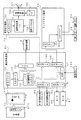
以下、本発明の実施の形態を、図面を参照して説明する。まず、遊技機の一例であるパチンコ遊技機1の全体の構成について説明する。図1はパチンコ遊技機1を正面からみた正面図である。
Hereinafter, embodiments of the present invention will be described with reference to the drawings. First, the overall configuration of a
パチンコ遊技機1は、縦長の方形状に形成された外枠(図示せず)と、外枠の内側に開閉可能に取り付けられた遊技枠とで構成される。また、パチンコ遊技機1は、遊技枠に開閉可能に設けられている額縁状に形成されたガラス扉枠2を有する。遊技枠は、外枠に対して開閉自在に設置される前面枠(図示せず)と、機構部品等が取り付けられる機構板(図示せず)と、それらに取り付けられる種々の部品(後述する遊技盤6を除く)とを含む構造体である。
The
ガラス扉枠2の下部表面には打球供給皿(上皿)3がある。打球供給皿3の下部には、打球供給皿3に収容しきれない遊技球を貯留する余剰球受皿4や、打球を発射する打球操作ハンドル(操作ノブ)5が設けられている。また、ガラス扉枠2の背面には、遊技盤6が着脱可能に取り付けられている。なお、遊技盤6は、それを構成する板状体と、その板状体に取り付けられた種々の部品とを含む構造体である。また、遊技盤6の前面には、打ち込まれた遊技球が流下可能な遊技領域7が形成されている。
On the lower surface of the
遊技領域7の中央付近には、液晶表示装置(LCD)で構成された演出表示装置9が設けられている。演出表示装置9の円形の表示画面には、第1特別図柄または第2特別図柄の可変表示に同期した演出図柄の可変表示を行う演出図柄表示領域がある。よって、演出表示装置9は、演出図柄の可変表示を行う可変表示装置に相当する。演出図柄表示領域には、例えば「左」、「中」、「右」の3つの装飾用(演出用)の演出図柄を可変表示する図柄表示エリアがある。図柄表示エリアには「左」、「中」、「右」の各図柄表示エリア(図129等の図柄表示エリア9L、9C、9Rを参照)があるが、図柄表示エリアの位置は、演出表示装置9の表示画面において固定的でなくてもよいし、図柄表示エリアの3つ領域が離れてもよい。演出表示装置9は、演出制御基板に搭載されている演出制御用マイクロコンピュータによって制御される。演出制御用マイクロコンピュータが、第1特別図柄表示器8aで第1特別図柄の可変表示が実行されているときに、その可変表示に伴って演出表示装置9で演出表示を実行させ、第2特別図柄表示器8bで第2特別図柄の可変表示が実行されているときに、その可変表示に伴って演出表示装置9で演出表示を実行させるので、遊技の進行状況を把握しやすくすることができる。
An
遊技盤6における下部の左側には、識別情報としての第1特別図柄を可変表示する第1特別図柄表示器(第1可変表示部)8aが設けられている。この実施の形態では、第1特別図柄表示器8aは、0〜9の数字を可変表示可能な簡易で小型の表示器(例えば7セグメントLED)で実現されている。すなわち、第1特別図柄表示器8aは、0〜9の数字(または、記号)を可変表示するように構成されている。遊技盤6における下部の右側には、識別情報としての第2特別図柄を可変表示する第2特別図柄表示器(第2可変表示部)8bが設けられている。第2特別図柄表示器8bは、0〜9の数字を可変表示可能な簡易で小型の表示器(例えば7セグメントLED)で実現されている。すなわち、第2特別図柄表示器8bは、0〜9の数字(または、記号)を可変表示するように構成されている。
On the left side of the lower part of the
小型の表示器は、例えば方形状に形成されている。また、この実施の形態では、第1特別図柄の種類と第2特別図柄の種類とは同じ(例えば、ともに0〜9の数字)であるが、種類が異なっていてもよい。また、第1特別図柄表示器8aおよび第2特別図柄表示器8bは、それぞれ、例えば、00〜99の数字(または、2桁の記号)を可変表示するように構成されていてもよい。
The small display is formed in a square shape, for example. In this embodiment, the type of the first special symbol and the type of the second special symbol are the same (for example, both 0 to 9), but the types may be different. Further, the first
以下、第1特別図柄と第2特別図柄とを特別図柄と総称することがあり、第1特別図柄表示器8aと第2特別図柄表示器8bとを特別図柄表示器(可変表示部)と総称することがある。
Hereinafter, the first special symbol and the second special symbol may be collectively referred to as a special symbol, and the first
第1特別図柄または第2特別図柄の可変表示は、可変表示の実行条件である第1始動条件または第2始動条件が成立(例えば、遊技球が第1始動入賞口13または第2始動入賞口14に入賞したこと)した後、可変表示の開始条件(例えば、保留記憶数が0でない場合であって、第1特別図柄および第2特別図柄の可変表示が実行されていない状態であり、かつ、大当り遊技が実行されていない状態)が成立したことにもとづいて開始され、可変表示時間が経過すると表示結果(停止図柄)を導出表示する。なお、入賞とは、入賞口などのあらかじめ入賞領域として定められている領域に遊技球が通過したことである。また、表示結果を導出表示するとは、図柄(識別情報の例)を停止表示させることである(いわゆる再変動の前の停止を除く。)。また、この実施の形態では、第1始動入賞口13への入賞および第2始動入賞口14への入賞に関わりなく、始動入賞が生じた順に可変表示の開始条件を成立させるが、第1始動入賞口13への入賞と第2始動入賞口14への入賞のうちのいずれかを優先させて可変表示の開始条件を成立させるようにしてもよい。例えば第1始動入賞口13への入賞を優先させる場合には、第1特別図柄および第2特別図柄の可変表示が実行されていない状態であり、かつ、大当り遊技が実行されていない状態であれば、第2保留記憶数が0でない場合でも、第1保留記憶数が0になるまで、第1特別図柄の可変表示を続けて実行する。
For the variable display of the first special symbol or the second special symbol, the first start condition or the second start condition, which is the variable display execution condition, is satisfied (for example, the game ball has the first
第1特別図柄表示器8aの近傍には、第1特別図柄表示器8aによる第1特別図柄の可変表示時間中に、装飾用(演出用)の図柄としての第1飾り図柄の可変表示を行う第1飾り図柄表示器9aが設けられている。この実施の形態では、第1飾り図柄表示器9aは、2つのLEDで構成されている。第1飾り図柄表示器9aは、演出制御基板に搭載されている演出制御用マイクロコンピュータによって制御される。また、第2特別図柄表示器8bの近傍には、第2特別図柄表示器8bによる第2特別図柄の可変表示時間中に、装飾用(演出用)の図柄としての第2飾り図柄の可変表示を行う第2飾り図柄表示器9bが設けられている。第2飾り図柄表示器9bは、2つのLEDで構成されている。第2飾り図柄表示器9bは、演出制御基板に搭載されている演出制御用マイクロコンピュータによって制御される。
In the vicinity of the first
なお、第1飾り図柄と第2飾り図柄とを、飾り図柄と総称することがあり、第1飾り図柄表示器9aと第2飾り図柄表示器9bを、飾り図柄表示器と総称することがある。
The first decorative symbol and the second decorative symbol may be collectively referred to as a decorative symbol, and the first
飾り図柄の変動(可変表示)は、2つのLEDが交互に点灯する状態を継続することによって実現される。第1特別図柄表示器8aにおける第1特別図柄の可変表示と、第1飾り図柄表示器9aにおける第1飾り図柄の可変表示とは同期している。第2特別図柄表示器8bにおける第2特別図柄の可変表示と、第2飾り図柄表示器9bにおける第2飾り図柄の可変表示とは同期している。同期とは、可変表示の開始時点および終了時点が同じであって、可変表示の期間が同じであることをいう。また、第1特別図柄表示器8aにおいて大当り図柄が停止表示されるときには、第1飾り図柄表示器9aにおいて大当りを想起させる側のLEDが点灯されたままになる。第2特別図柄表示器8bにおいて大当り図柄が停止表示されるときには、第2飾り図柄表示器9bにおいて大当りを想起させる側のLEDが点灯されたままになる。なお、第1飾り図柄表示器9aおよび第2飾り図柄表示器9bの機能を、演出表示装置9で実現するようにしてもよい。すなわち、第1飾り図柄および第2飾り図柄が、演出表示装置9の表示画面において画像として可変表示されるように制御してもよい。
The variation of the decorative pattern (variable display) is realized by continuing the state where the two LEDs are alternately lit. The variable display of the first special symbol on the first
演出表示装置9の下方には、第1始動入賞口13を有する入賞装置が設けられている。第1始動入賞口13に入賞した遊技球は、遊技盤6の背面に導かれ、第1始動口スイッチ13aによって検出される。
A winning device having a first
また、第1始動入賞口(第1始動口)13を有する入賞装置の下方には、遊技球が入賞可能な第2始動入賞口14を有する可変入賞球装置15が設けられている。第2始動入賞口(第2始動口)14に入賞した遊技球は、遊技盤6の背面に導かれ、第2始動口スイッチ14aによって検出される。可変入賞球装置15は、ソレノイド16によって開状態とされる。可変入賞球装置15が開状態になることによって、遊技球が第2始動入賞口14に入賞可能になり(始動入賞し易くなり)、遊技者にとって有利な状態になる。可変入賞球装置15が開状態になっている状態では、第1始動入賞口13よりも、第2始動入賞口14に遊技球が入賞しやすい。また、可変入賞球装置15が閉状態になっている状態では、遊技球は第2始動入賞口14に入賞しない。従って、可変入賞球装置15が閉状態になっている状態では、第2始動入賞口14よりも、第1始動入賞口13に遊技球が入賞しやすい。なお、可変入賞球装置15が閉状態になっている状態において、入賞はしづらいものの、入賞することは可能である(すなわち、遊技球が入賞しにくい)ように構成されていてもよい。
A variable winning
以下、第1始動入賞口13と第2始動入賞口14とを総称して始動入賞口または始動口ということがある。
Hereinafter, the first
可変入賞球装置15が開放状態に制御されているときには可変入賞球装置15に向かう遊技球は第2始動入賞口14に極めて入賞しやすい。そして、第1始動入賞口13は演出表示装置9の直下に設けられているが、演出表示装置9の下端と第1始動入賞口13との間の間隔をさらに狭めたり、第1始動入賞口13の周辺で釘を密に配置したり、第1始動入賞口13の周辺での釘配列を遊技球を第1始動入賞口13に導きづらくして、第2始動入賞口14の入賞率の方を第1始動入賞口13の入賞率よりもより高くするようにしてもよい。
When the variable winning
なお、この実施の形態では、図1に示すように、第2始動入賞口14に対してのみ開閉動作を行う可変入賞球装置15が設けられているが、第1始動入賞口13および第2始動入賞口14のいずれについても開閉動作を行う可変入賞球装置が設けられている構成であってもよい。
In this embodiment, as shown in FIG. 1, the variable winning
第1飾り図柄表示器9aの側方には、第1始動入賞口13に入った有効入賞球数すなわち第1保留記憶数(保留記憶を、始動記憶または始動入賞記憶ともいう。)を表示する4つの表示器からなる第1特別図柄保留記憶表示器18aが設けられている。第1特別図柄保留記憶表示器18aは、有効始動入賞がある毎に、点灯する表示器の数を1増やす。そして、第1特別図柄表示器8aでの可変表示が開始される毎に、点灯する表示器の数を1減らす。
On the side of the first
第2飾り図柄表示器9bの側方には、第2始動入賞口14に入った有効入賞球数すなわち第2保留記憶数を表示する4つの表示器からなる第2特別図柄保留記憶表示器18bが設けられている。第2特別図柄保留記憶表示器18bは、有効始動入賞がある毎に、点灯する表示器の数を1増やす。そして、第2特別図柄表示器8bでの可変表示が開始される毎に、点灯する表示器の数を1減らす。
On the side of the second decorative symbol display 9b is a second special symbol reserved
また、演出表示装置9の表示画面には、第1保留記憶数と第2保留記憶数との合計である合計数(合算保留記憶数)を表示する領域(以下、合算保留記憶表示部18cという。)が設けられている。合計数を表示する合算保留記憶表示部18cが設けられているので、可変表示の開始条件が成立していない実行条件の成立数の合計を把握しやすくすることができる。なお、第1特別図柄保留記憶表示器18aおよび第2特別図柄保留記憶表示器18bが設けられているので、合算保留記憶表示部18cは、必ずしも設けられていなくてもよい。
In addition, the display screen of the
演出表示装置9は、第1特別図柄表示器8aによる第1特別図柄の可変表示時間中、および第2特別図柄表示器8bによる第2特別図柄の可変表示時間中に、装飾用(演出用)の図柄としての演出図柄の可変表示を行う。第1特別図柄表示器8aにおける第1特別図柄の可変表示と、演出表示装置9における演出図柄の可変表示とは同期している。また、第2特別図柄表示器8bにおける第2特別図柄の可変表示と、演出表示装置9における演出図柄の可変表示とは同期している。また、第1特別図柄表示器8aにおいて大当り図柄が停止表示されるときと、第2特別図柄表示器8bにおいて大当り図柄が停止表示されるときには、演出表示装置9において大当りを想起させるような演出図柄の組み合わせが停止表示される。
The
演出表示装置9の周囲の飾り部において、左側には、モータ86の回転軸に取り付けられ、モータ86が回転すると移動する可動部材78が設けられている。この実施の形態では、可動部材78は、擬似連の演出や予告演出(可動物予告演出)が実行されるときに動作する。また、演出表示装置9の周囲の飾り部において、左右の下方には、モータ87の回転軸に取り付けられ、モータ87が回転すると移動する羽根形状の可動部材(以下、演出羽根役物という。)79a,79bが設けられている。この実施の形態では、演出羽根役物79a,79bは、予告演出(演出羽根役物予告演出)が実行されるときに動作する。
On the left side of the decorative portion around the
また、図1に示すように、可変入賞球装置15の下方には、特別可変入賞球装置20が設けられている。特別可変入賞球装置20は開閉板を備え、第1特別図柄表示器8aに特定表示結果(大当り図柄)が導出表示されたときと、第2特別図柄表示器8bに特定表示結果(大当り図柄)が導出表示されたときに生起する特定遊技状態(大当り遊技状態)においてソレノイド21によって開閉板が開放状態に制御されることによって、入賞領域となる大入賞口が開放状態になる。大入賞口に入賞した遊技球はカウントスイッチ23で検出される。
Further, as shown in FIG. 1, a special variable winning
遊技領域6には、遊技球の入賞にもとづいてあらかじめ決められている所定数の景品遊技球の払出を行うための入賞口(普通入賞口)29,30,33,39も設けられている。入賞口29,30,33,39に入賞した遊技球は、入賞口スイッチ29a,30a,33a,39aで検出される。
The
遊技盤6の右側方には、普通図柄表示器10が設けられている。普通図柄表示器10は、普通図柄と呼ばれる複数種類の識別情報(例えば、「○」および「×」)を可変表示する。
A
遊技球がゲート32を通過しゲートスイッチ32aで検出されると、普通図柄表示器10の表示の可変表示が開始される。この実施の形態では、上下のランプ(点灯時に図柄が視認可能になる)が交互に点灯することによって可変表示が行われ、例えば、可変表示の終了時に下側のランプが点灯すれば当りとなる。そして、普通図柄表示器10における停止図柄が所定の図柄(当り図柄)である場合に、可変入賞球装置15が所定回数、所定時間だけ開状態になる。すなわち、可変入賞球装置15の状態は、普通図柄の停止図柄が当り図柄である場合に、遊技者にとって不利な状態から有利な状態(第2始動入賞口14に遊技球が入賞可能な状態)に変化する。普通図柄表示器10の近傍には、ゲート32を通過した入賞球数を表示する4つのLEDによる表示部を有する普通図柄保留記憶表示器41が設けられている。ゲート32への遊技球の通過がある毎に、すなわちゲートスイッチ32aによって遊技球が検出される毎に、普通図柄保留記憶表示器41は点灯するLEDを1増やす。そして、普通図柄表示器10の可変表示が開始される毎に、点灯するLEDを1減らす。さらに、通常状態に比べて大当りとすることに決定される確率が高い状態である確変状態では、普通図柄表示器10における停止図柄が当り図柄になる確率が高められるとともに、可変入賞球装置15の開放時間と開放回数が高められる。また、確変状態ではないが図柄の変動時間が短縮されている時短状態(特別図柄の可変表示時間が短縮される遊技状態)でも、可変入賞球装置15の開放時間と開放回数が高められる。
When the game ball passes through the
遊技盤6の遊技領域7の左右周辺には、遊技中に点滅表示される装飾LED25が設けられ、下部には、入賞しなかった打球が取り込まれるアウト口26がある。また、遊技領域7の外側の左右上部には、所定の音声出力として効果音や音声を発声する2つのスピーカ27が設けられている。遊技領域7の外周には、前面枠に設けられた枠LED28が設けられている。
On the left and right sides of the
打球供給皿3を構成する部材においては、遊技者により操作可能な操作手段としての操作ボタン120が設けられている。操作ボタン120には、遊技者が押圧操作をすることが可能な押しボタンスイッチが設けられている。なお、操作ボタン120は、遊技者による押圧操作が可能な押しボタンスイッチが設けられているだけでなく、遊技者による回転操作が可能なダイヤルも設けられている。遊技者は、ダイヤルを回転操作することによって、所定の選択(例えば演出の選択)を行うことができる。
The members constituting the hitting
遊技機には、遊技者が打球操作ハンドル5を操作することに応じて駆動モータを駆動し、駆動モータの回転力を利用して遊技球を遊技領域7に発射する打球発射装置(図示せず)が設けられている。打球発射装置から発射された遊技球は、遊技領域7を囲むように円形状に形成された打球レールを通って遊技領域7に入り、その後、遊技領域7を下りてくる。遊技球が第1始動入賞口13に入り第1始動口スイッチ13aで検出されると、第1特別図柄の可変表示を開始できる状態であれば(例えば、特別図柄の可変表示が終了し、第1の開始条件が成立したこと)、第1特別図柄表示器8aにおいて第1特別図柄の可変表示(変動)が開始されるとともに、第1飾り図柄表示器9aにおいて第1飾り図柄の可変表示が開始され、演出表示装置9において演出図柄の可変表示が開始される。すなわち、第1特別図柄、第1飾り図柄および演出図柄の可変表示は、第1始動入賞口13への入賞に対応する。第1特別図柄の可変表示を開始できる状態でなければ、第1保留記憶数が上限値に達していないことを条件として、第1保留記憶数を1増やす。
In the gaming machine, a ball striking device (not shown) that drives a driving motor in response to a player operating the batting operation handle 5 and uses the rotational force of the driving motor to launch a gaming ball to the gaming area 7. ) Is provided. A game ball launched from the ball striking device enters the
遊技球が第2始動入賞口14に入り第2始動口スイッチ14aで検出されると、第2特別図柄の可変表示を開始できる状態であれば(例えば、特別図柄の可変表示が終了し、第2の開始条件が成立したこと)、第2特別図柄表示器8bにおいて第2特別図柄の可変表示(変動)が開始されるとともに、第2飾り図柄表示器9bにおいて第2飾り図柄の可変表示が開始され、演出表示装置9において演出図柄の可変表示が開始される。すなわち、第2特別図柄、第2飾り図柄および演出図柄の可変表示は、第2始動入賞口14への入賞に対応する。第2特別図柄の可変表示を開始できる状態でなければ、第2保留記憶数が上限値に達していないことを条件として、第2保留記憶数を1増やす。
When the game ball enters the second
この実施の形態では、確変大当りであることや確変昇格演出(確変状態に昇格することを示す特別な演出)において確変に昇格したことを報知した場合には、遊技状態を高確率状態に移行するとともに、遊技球が始動入賞しやすくなる(すなわち、特別図柄表示器8a,8bや演出表示装置9における可変表示の実行条件が成立しやすくなる)ように制御された遊技状態である高ベース状態に移行する。また、遊技状態が時短状態に移行されたときも、高ベース状態に移行する。高ベース状態である場合には、例えば、高ベース状態でない場合と比較して、可変入賞球装置15が開状態となる頻度が高められたり、可変入賞球装置15が開状態となる時間が延長されたりして、始動入賞しやすくなる。
In this embodiment, when it is informed that it is a probable big hit or a probable promotion effect (a special effect indicating promotion to a probable state), the gaming state is shifted to a high probability state. At the same time, the game ball is controlled to be in a high base state that is controlled so as to make it easier for the game ball to start and win (that is, the execution conditions for variable display in the
なお、可変入賞球装置15が開状態となる時間を延長する(開放延長状態ともいう)のでなく、普通図柄表示器10における停止図柄が当り図柄になる確率が高められる普通図柄確変状態に移行することによって、高ベース状態に移行してもよい。普通図柄表示器10における停止図柄が所定の図柄(当り図柄)となると、可変入賞球装置15が所定回数、所定時間だけ開状態になる。この場合、普通図柄確変状態に移行制御することによって、普通図柄表示器10における停止図柄が当り図柄になる確率が高められ、可変入賞球装置15が開状態となる頻度が高まる。従って、普通図柄確変状態に移行すれば、可変入賞球装置15の開放時間と開放回数が高められ、始動入賞しやすい状態(高ベース状態)となる。すなわち、可変入賞球装置15の開放時間と開放回数は、普通図柄の停止図柄が当り図柄であったり、特別図柄の停止図柄が確変図柄である場合等に高められ、遊技者にとって不利な状態から有利な状態(始動入賞しやすい状態)に変化する。なお、開放回数が高められることは、閉状態から開状態になることも含む概念である。
Instead of extending the time during which the variable winning
また、普通図柄表示器10における普通図柄の変動時間(可変表示期間)が短縮される普通図柄時短状態に移行することによって、高ベース状態に移行してもよい。普通図柄時短状態では、普通図柄の変動時間が短縮されるので、普通図柄の変動が開始される頻度が高くなり、結果として普通図柄が当りとなる頻度が高くなる。従って、普通図柄が当たりとなる頻度が高くなることによって、可変入賞球装置15が開状態となる頻度が高くなり、始動入賞しやすい状態(高ベース状態)となる。
Moreover, you may transfer to a high base state by shifting to the normal symbol time short state where the fluctuation time (variable display period) of the normal symbol in the
また、特別図柄や演出図柄の変動時間(可変表示期間)が短縮される時短状態に移行することによって、特別図柄や演出図柄の変動時間が短縮されるので、特別図柄や演出図柄の変動が開始される頻度が高くなり(換言すれば、保留記憶の消化が速くなる。)、結果として、始動入賞しやすくなり大当り遊技が行われる可能性が高まる。 In addition, the change time of special symbols and production symbols will be shortened by shifting to the short time state when the variation time (variable display period) of special symbols and production symbols is shortened. (In other words, the digestion of the stored memory becomes faster), and as a result, it is easier to start a winning and the possibility of playing a big hit game is increased.
さらに、上記に示した全ての状態(開放延長状態、普通図柄確変状態、普通図柄時短状態および特別図柄時短状態)に移行させることによって、始動入賞しやすくなる(高ベース状態に移行する)ようにしてもよい。また、上記に示した各状態(開放延長状態、普通図柄確変状態、普通図柄時短状態および特別図柄時短状態)のうちのいずれか複数の状態に移行させることによって、始動入賞しやすくなる(高ベース状態に移行する)ようにしてもよい。 Furthermore, by shifting to all the states shown above (open extended state, normal symbol probability changing state, normal symbol short time state, and special symbol short time state), it will be easier to win a start (shift to a high base state). May be. In addition, it is easier to win a start (high base) by shifting to any one of the above states (open extended state, normal symbol probability changing state, normal symbol short time state, and special symbol short time state). Transition to a state).
図2は、主基板(遊技制御基板)31における回路構成の一例を示すブロック図である。なお、図2は、払出制御基板37および演出制御基板80等も示されている。主基板31には、プログラムに従ってパチンコ遊技機1を制御する遊技制御用マイクロコンピュータ(遊技制御手段に相当)560が搭載されている。遊技制御用マイクロコンピュータ560は、ゲーム制御(遊技進行制御)用のプログラム等を記憶するROM54、ワークメモリとして使用される記憶手段としてのRAM55、プログラムに従って制御動作を行うCPU56およびI/Oポート部57を含む。この実施の形態では、ROM54およびRAM55は遊技制御用マイクロコンピュータ560に内蔵されている。すなわち、遊技制御用マイクロコンピュータ560は、1チップマイクロコンピュータである。1チップマイクロコンピュータには、少なくともCPU56のほかRAM55が内蔵されていればよく、ROM54は外付けであっても内蔵されていてもよい。また、I/Oポート部57は、外付けであってもよい。遊技制御用マイクロコンピュータ560には、さらに、ハードウェア乱数(ハードウェア回路が発生する乱数)を発生する乱数回路503が内蔵されている。
FIG. 2 is a block diagram showing an example of the circuit configuration of the main board (game control board) 31. FIG. 2 also shows a
また、RAM55は、その一部または全部が電源基板910において作成されるバックアップ電源によってバックアップされている不揮発性記憶手段としてのバックアップRAMである。すなわち、遊技機に対する電力供給が停止しても、所定期間(バックアップ電源としてのコンデンサが放電してバックアップ電源が電力供給不能になるまで)は、RAM55の一部または全部の内容は保存される。特に、少なくとも、遊技状態すなわち遊技制御手段の制御状態に応じたデータ(特別図柄プロセスフラグなど)と未払出賞球数を示すデータは、バックアップRAMに保存される。遊技制御手段の制御状態に応じたデータとは、停電等が生じた後に復旧した場合に、そのデータにもとづいて、制御状態を停電等の発生前に復旧させるために必要なデータである。また、制御状態に応じたデータと未払出賞球数を示すデータとを遊技の進行状態を示すデータと定義する。なお、この実施の形態では、RAM55の全部が、電源バックアップされているとする。
The
なお、遊技制御用マイクロコンピュータ560においてCPU56がROM54に格納されているプログラムに従って制御を実行するので、以下、遊技制御用マイクロコンピュータ560(またはCPU56)が実行する(または、処理を行う)ということは、具体的には、CPU56がプログラムに従って制御を実行することである。このことは、主基板31以外の他の基板に搭載されているマイクロコンピュータについても同様である。
In the
乱数回路503は、特別図柄の可変表示の表示結果により大当りとするか否か判定するための判定用の乱数を発生するために用いられるハードウェア回路である。乱数回路503は、初期値(例えば、0)と上限値(例えば、65535)とが設定された数値範囲内で、数値データを、設定された更新規則に従って更新し、ランダムなタイミングで発生する始動入賞時が数値データの読出(抽出)時であることにもとづいて、読出される数値データが乱数値となる乱数発生機能を有する。
The
乱数回路503は、数値データの更新範囲の選択設定機能(初期値の選択設定機能、および、上限値の選択設定機能)、数値データの更新規則の選択設定機能、および数値データの更新規則の選択切換え機能等の各種の機能を有する。このような機能によって、生成する乱数のランダム性を向上させることができる。
The
また、遊技制御用マイクロコンピュータ560は、乱数回路503が更新する数値データの初期値を設定する機能を有している。例えば、ROM54等の所定の記憶領域に記憶された遊技制御用マイクロコンピュータ560のIDナンバ(遊技制御用マイクロコンピュータ560の各製品ごとに異なる数値で付与されたIDナンバ)を用いて所定の演算を行なって得られた数値データを、乱数回路503が更新する数値データの初期値として設定する。そのような処理を行うことによって、乱数回路503が発生する乱数のランダム性をより向上させることができる。
Further, the
また、ゲートスイッチ32a、始動口スイッチ13a、カウントスイッチ23、入賞口スイッチ29a,30a,33a,39aからの検出信号を遊技制御用マイクロコンピュータ560に与える入力ドライバ回路58も主基板31に搭載されている。また、可変入賞球装置15を開閉するソレノイド16、および大入賞口を形成する特別可変入賞球装置20を開閉するソレノイド21を遊技制御用マイクロコンピュータ560からの指令に従って駆動する出力回路59も主基板31に搭載されている。
Further, an
また、遊技制御用マイクロコンピュータ560は、特別図柄を可変表示する第1特別図柄表示器8a、第2特別図柄表示器8b、普通図柄を可変表示する普通図柄表示器10、第1特別図柄保留記憶表示器18a、第2特別図柄保留記憶表示器18bおよび普通図柄保留記憶表示器41の表示制御を行う。
In addition, the
なお、大当り遊技状態の発生を示す大当り情報等の情報出力信号をホールコンピュータ等の外部装置に対して出力する情報出力回路(図示せず)も主基板31に搭載されている。
An information output circuit (not shown) that outputs an information output signal such as jackpot information indicating the occurrence of a jackpot gaming state to an external device such as a hall computer is also mounted on the
この実施の形態では、演出制御基板80に搭載されている演出制御手段(演出制御用マイクロコンピュータで構成される。)が、中継基板77を介して遊技制御用マイクロコンピュータ560から演出内容を指示する演出制御コマンドを受信し、飾り図柄を可変表示する第1飾り図柄表示器9aおよび第2飾り図柄表示器9bと、演出図柄を可変表示する演出表示装置9との表示制御を行う。
In this embodiment, the effect control means (configured by the effect control microcomputer) mounted on the
また、演出制御基板80に搭載されている演出制御手段が、ランプドライバ基板35を介して、遊技盤に設けられている装飾LED25、および枠側に設けられている枠LED28の表示制御を行うとともに、音声出力基板70を介してスピーカ27からの音出力の制御を行う。
The effect control means mounted on the
図3は、中継基板77、演出制御基板80、ランプドライバ基板35および音声出力基板70の回路構成例を示すブロック図である。なお、図3に示す例では、ランプドライバ基板35および音声出力基板70には、マイクロコンピュータは搭載されていないが、マイクロコンピュータを搭載してもよい。また、ランプドライバ基板35および音声出力基板70を設けずに、演出制御に関して演出制御基板80のみを設けてもよい。
FIG. 3 is a block diagram illustrating a circuit configuration example of the
演出制御基板80は、演出制御用CPU101、および演出図柄プロセスフラグ等の演出に関する情報を記憶するRAMを含む演出制御用マイクロコンピュータ100を搭載している。なお、RAMは外付けであってもよい。この実施の形態では、演出制御用マイクロコンピュータ100におけるRAMは電源バックアップされていない。演出制御基板80において、演出制御用CPU101は、内蔵または外付けのROM(図示せず)に格納されたプログラムに従って動作し、中継基板77を介して入力される主基板31からの取込信号(演出制御INT信号)に応じて、入力ドライバ102および入力ポート103を介して演出制御コマンドを受信する。また、演出制御用CPU101は、演出制御コマンドにもとづいて、VDP(ビデオディスプレイプロセッサ)109に演出表示装置9の表示制御を行わせる。
The
この実施の形態では、演出制御用マイクロコンピュータ100と共動して演出表示装置9の表示制御を行うVDP109が演出制御基板80に搭載されている。VDP109は、演出制御用マイクロコンピュータ100とは独立したアドレス空間を有し、そこにVRAMをマッピングする。VRAMは、画像データを展開するためのバッファメモリである。そして、VDP109は、VRAM内の画像データをフレームメモリを介して演出表示装置9に出力する。
In this embodiment, a
演出制御用CPU101は、受信した演出制御コマンドに従ってCGROM(図示せず)から必要なデータを読み出すための指令をVDP109に出力する。CGROMは、演出表示装置9に表示されるキャラクタ画像データや動画像データ、具体的には、人物、文字、図形や記号等(演出図柄を含む)、および背景画像のデータをあらかじめ格納しておくためのROMである。VDP109は、演出制御用CPU101の指令に応じて、CGROMから画像データを読み出す。そして、VDP109は、読み出した画像データにもとづいて表示制御を実行する。
The
演出制御コマンドおよび演出制御INT信号は、演出制御基板80において、まず、入力ドライバ102に入力する。入力ドライバ102は、中継基板77から入力された信号を演出制御基板80の内部に向かう方向にしか通過させない(演出制御基板80の内部から中継基板77への方向には信号を通過させない)信号方向規制手段としての単方向性回路でもある。
The effect control command and the effect control INT signal are first input to the
中継基板77には、主基板31から入力された信号を演出制御基板80に向かう方向にしか通過させない(演出制御基板80から中継基板77への方向には信号を通過させない)信号方向規制手段としての単方向性回路74が搭載されている。単方向性回路として、例えばダイオードやトランジスタが使用される。図3には、ダイオードが例示されている。また、単方向性回路は、各信号毎に設けられる。さらに、単方向性回路である出力ポート571を介して主基板31から演出制御コマンドおよび演出制御INT信号が出力されるので、中継基板77から主基板31の内部に向かう信号が規制される。すなわち、中継基板77からの信号は主基板31の内部(遊技制御用マイクロコンピュータ560側)に入り込まない。なお、出力ポート571は、図2に示されたI/Oポート部57の一部である。また、出力ポート571の外側(中継基板77側)に、さらに、単方向性回路である信号ドライバ回路が設けられていてもよい。
As a signal direction regulating means, the signal inputted from the
また、演出制御用CPU101は、出力ポート106を介して、可動部材78を動作させるためにモータ86を駆動する。また、演出制御用CPU101は、出力ポート106を介して、演出羽根役物79a,79bを動作させるためのモータ87を駆動する。
The
また、演出制御用CPU101は、入力ポート107を介して、遊技者による操作ボタン120の押圧操作に応じて操作ボタン120からの信号を入力する。
Further, the
さらに、演出制御用CPU101は、出力ポート105を介してランプドライバ基板35に対してLEDを駆動する信号を出力する。また、演出制御用CPU101は、出力ポート104を介して音声出力基板70に対して音番号データを出力する。
Further, the
ランプドライバ基板35において、LEDを駆動する信号は、入力ドライバ351を介してLEDドライバ352に入力される。LEDドライバ352は、LEDを駆動する信号にもとづいて枠LED28などの枠側に設けられている発光体に電流を供給する。また、遊技盤側に設けられている装飾LED25に電流を供給する。
In the
音声出力基板70において、音番号データは、入力ドライバ702を介して音声合成用IC703に入力される。音声合成用IC703は、音番号データに応じた音声や効果音を発生し増幅回路705に出力する。増幅回路705は、音声合成用IC703の出力レベルを、ボリューム706で設定されている音量に応じたレベルに増幅した音声信号をスピーカ27に出力する。音声データROM704には、音番号データに応じた制御データが格納されている。音番号データに応じた制御データは、所定期間(例えば演出図柄の変動期間)における効果音または音声の出力態様を時系列的に示すデータの集まりである。
In the
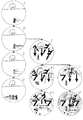
図4は、可動部材の動作の具体例を示す説明図である。なお、図4に示す例では、演出表示装置9における再変動演出(擬似連の演出)が実行されるときの可動部材78の動作を示している。再変動演出では、図4(A)に示す状態(左中右の演出図柄が停止している状態)から演出図柄の変動が開始されてから、所定期間演出図柄の変動が実行され(図4(B),(C)参照)、所定期間が経過すると左中右の演出図柄が仮停止する(図4(D)参照)。そして、所定の仮停止期間が経過すると、左中右の演出図柄が再変動し(図4(E)参照)、所定の再変動期間が経過すると、左中右の演出図柄は最終停止(確定)する(図4(F)参照)。図4に示す例では、初回変動の期間において、可動部材78が動作(演出表示装置9の表示画面に進入した後、元の位置(表示画面外)に戻るように動作)し、初回変動に続く再変動期間においても、可動部材78が動作する。なお、図4に示す例は、1回の仮停止が行われる場合の例である。その後、リーチ演出が実行された後、左中右の演出図柄は最終停止(確定)する。なお、ここでは、再変動演出が終了するときにリーチになると説明したが、再変動演出が終了するときに、演出図柄はリーチにならず最終停止する場合もある。
FIG. 4 is an explanatory diagram showing a specific example of the operation of the movable member. In the example shown in FIG. 4, the operation of the
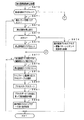
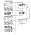
次に、遊技機の動作について説明する。図5は、主基板31における遊技制御用マイクロコンピュータ560が実行するメイン処理を示すフローチャートである。遊技機に対して電源が投入され電力供給が開始されると、リセット信号が入力されるリセット端子の入力レベルがハイレベルになり、遊技制御用マイクロコンピュータ560(具体的には、CPU56)は、プログラムの内容が正当か否か確認するための処理であるセキュリティチェック処理を実行した後、ステップS1以降のメイン処理を開始する。メイン処理において、CPU56は、まず、必要な初期設定を行う。
Next, the operation of the gaming machine will be described. FIG. 5 is a flowchart showing main processing executed by the
初期設定処理において、CPU56は、まず、割込禁止に設定する(ステップS1)。次に、割込モードを割込モード2に設定し(ステップS2)、スタックポインタにスタックポインタ指定アドレスを設定する(ステップS3)。そして、内蔵デバイスの初期化(内蔵デバイス(内蔵周辺回路)であるCTC(カウンタ/タイマ)およびPIO(パラレル入出力ポート)の初期化など)を行った後(ステップS4)、RAM55をアクセス可能状態に設定する(ステップS5)。なお、割込モード2は、CPU56が内蔵する特定レジスタ(Iレジスタ)の値(1バイト)と内蔵デバイスが出力する割込ベクタ(1バイト:最下位ビット0)とから合成されるアドレスが、割込番地を示すモードである。
In the initial setting process, the
次いで、CPU56は、入力ポートを介して入力されるクリアスイッチ(例えば、電源基板に搭載されている。)の出力信号の状態を確認する(ステップS6)。その確認においてオンを検出した場合には、CPU56は、通常の初期化処理を実行する(ステップS10〜S15)。
Next, the
クリアスイッチがオンの状態でない場合には、遊技機への電力供給が停止したときにバックアップRAM領域のデータ保護処理(例えばパリティデータの付加等の電力供給停止時処理)が行われたか否か確認する(ステップS7)。そのような保護処理が行われていないことを確認したら、CPU56は初期化処理を実行する。バックアップRAM領域にバックアップデータがあるか否かは、例えば、電力供給停止時処理においてバックアップRAM領域に設定されるバックアップフラグの状態によって確認される。
If the clear switch is not on, check whether data protection processing of the backup RAM area (for example, power supply stop processing such as addition of parity data) was performed when power supply to the gaming machine was stopped (Step S7). When it is confirmed that such protection processing is not performed, the
電力供給停止時処理が行われたことを確認したら、CPU56は、バックアップRAM領域のデータチェックを行う(ステップS8)。この実施の形態では、データチェックとしてパリティチェックを行う。よって、ステップS8では、算出したチェックサムと、電力供給停止時処理で同一の処理によって算出され保存されているチェックサムとを比較する。不測の停電等の電力供給停止が生じた後に復旧した場合には、バックアップRAM領域のデータは保存されているはずであるから、チェック結果(比較結果)は正常(一致)になる。チェック結果が正常でないということは、バックアップRAM領域のデータが、電力供給停止時のデータとは異なっていることを意味する。そのような場合には、内部状態を電力供給停止時の状態に戻すことができないので、電力供給の停止からの復旧時でない電源投入時に実行される初期化処理を実行する。
When it is confirmed that the power supply stop process has been performed, the
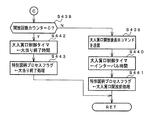
チェック結果が正常であれば、CPU56は、遊技制御手段の内部状態と演出制御手段等の電気部品制御手段の制御状態を電力供給停止時の状態に戻すための遊技状態復旧処理(ステップS41〜S43の処理)を行う。具体的には、ROM54に格納されているバックアップ時設定テーブルの先頭アドレスをポインタに設定し(ステップS41)、バックアップ時設定テーブルの内容を順次作業領域(RAM55内の領域)に設定する(ステップS42)。作業領域はバックアップ電源によって電源バックアップされている。バックアップ時設定テーブルには、作業領域のうち初期化してもよい領域についての初期化データが設定されている。ステップS41およびS42の処理によって、作業領域のうち初期化してはならない部分については、保存されていた内容がそのまま残る。初期化してはならない部分とは、例えば、電力供給停止前の遊技状態を示すデータ(特別図柄プロセスフラグ、確変フラグ、時短フラグなど)、出力ポートの出力状態が保存されている領域(出力ポートバッファ)、未払出賞球数を示すデータが設定されている部分などである。
If the check result is normal, the
また、CPU56は、電力供給復旧時の初期化コマンドとしての停電復旧指定コマンド(停電復旧1指定コマンド)を演出制御基板80に送信する(ステップS43)。そして、ステップS14に移行する。
Further, the
なお、この実施の形態では、バックアップフラグとチェックデータとの双方を用いてバックアップRAM領域のデータが保存されているか否か確認しているが、いずれか一方のみを用いてもよい。すなわち、バックアップフラグとチェックデータとのいずれかを、遊技状態復旧処理を実行するための契機としてもよい。 In this embodiment, it is confirmed whether the data in the backup RAM area is stored using both the backup flag and the check data. However, only one of them may be used. That is, either the backup flag or the check data may be used as an opportunity for executing the game state restoration process.
初期化処理では、CPU56は、まず、RAMクリア処理を行う(ステップS10)。なお、RAMクリア処理によって、所定のデータ(例えば大当り判定用乱数を生成するためのカウンタのカウント値のデータ)は0に初期化されるが、任意の値またはあらかじめ決められている値に初期化するようにしてもよい。また、RAM55の全領域を初期化せず、所定のデータ(例えば大当り判定用乱数を生成するためのカウンタのカウント値のデータ)をそのままにしてもよい。また、ROM54に格納されている初期化時設定テーブルの先頭アドレスをポインタに設定し(ステップS11)、初期化時設定テーブルの内容を順次RAM55における作業領域に設定する(ステップS12)。
In the initialization process, the
ステップS11およびS12の処理によって、特別図柄プロセスフラグなど制御状態に応じて選択的に処理を行うためのフラグに初期値が設定される。 By the processing in steps S11 and S12, an initial value is set to a flag for selectively performing processing according to the control state, such as a special symbol process flag.
また、CPU56は、サブ基板(主基板31以外のマイクロコンピュータが搭載された基板。)を初期化するための初期化指定コマンド(遊技制御用マイクロコンピュータ560が初期化処理を実行したことを示すコマンドでもある。)を演出制御基板80に送信する(ステップS13)。例えば、演出制御基板80に搭載されている演出制御用マイクロコンピュータ100は、初期化指定コマンドを受信すると、演出表示装置9において、遊技機の制御の初期化がなされたことを報知するための画面表示、すなわち初期化報知を行う。なお、初期化処理において、CPU56は、客待ちデモンストレーション指定(デモ指定)コマンドも送信する。
Further, the
また、CPU56は、乱数回路503を初期設定する乱数回路設定処理を実行する(ステップS14)。CPU56は、例えば、乱数回路設定プログラムに従って処理を実行することによって、乱数回路503にランダムRの値を更新させるための設定を行う。
Further, the
そして、CPU56は、所定時間(例えば2ms)毎に定期的にタイマ割込がかかるように遊技制御用マイクロコンピュータ560に内蔵されているCTCのレジスタの設定を行なう(ステップS15)。すなわち、初期値として例えば2msに相当する値が所定のレジスタ(時間定数レジスタ)に設定される。この実施の形態では、2ms毎に定期的にタイマ割込がかかるとする。
Then, the
初期化処理の実行(ステップS10〜S15)が完了すると、CPU56は、メイン処理で、表示用乱数更新処理(ステップS17)および初期値用乱数更新処理(ステップS18)を繰り返し実行する。表示用乱数更新処理および初期値用乱数更新処理を実行するときには割込禁止状態に設定し(ステップS16)、表示用乱数更新処理および初期値用乱数更新処理の実行が終了すると割込許可状態に設定する(ステップS19)。この実施の形態では、表示用乱数とは、変動パターン等を決定するための乱数であり、表示用乱数更新処理とは、表示用乱数を発生するためのカウンタのカウント値を更新する処理である。また、初期値用乱数更新処理とは、初期値用乱数を発生するためのカウンタのカウント値を更新する処理である。この実施の形態では、初期値用乱数とは、普通図柄の当りとするか否か決定するための乱数を発生するためのカウンタ(普通図柄当り判定用乱数発生カウンタ)等のカウント値の初期値を決定するための乱数である。後述する遊技の進行を制御する遊技制御処理(遊技制御用マイクロコンピュータ560が、遊技機に設けられている可変表示装置、可変入賞球装置、球払出装置等の遊技用の装置を、自身で制御する処理、または他のマイクロコンピュータに制御させるために指令信号を送信する処理、遊技装置制御処理ともいう)において、大当り判定用乱数発生カウンタ等のカウント値が1周(乱数の取りうる値の最小値から最大値までの間の数値の個数分歩進したこと)すると、そのカウンタに初期値が設定される。
When the execution of the initialization process (steps S10 to S15) is completed, the
タイマ割込が発生すると、CPU56は、図6に示すステップS20〜S34のタイマ割込処理を実行する。タイマ割込処理において、まず、電源断信号が出力されたか否か(オン状態になったか否か)を検出する電源断検出処理を実行する(ステップS20)。電源断信号は、例えば電源基板に搭載されている電源監視回路920が、遊技機に供給される電源の電圧の低下を検出した場合に出力する。そして、電源断検出処理において、CPU56は、電源断信号が出力されたことを検出したら、必要なデータをバックアップRAM領域に保存するための電力供給停止時処理を実行する。次いで、入力ドライバ回路58を介して、ゲートスイッチ32a、第1始動口スイッチ13a、第2始動口スイッチ14a、カウントスイッチ23、および入賞口スイッチ29a,30a,33a,39aの検出信号を入力し、それらの状態判定を行う(スイッチ処理:ステップS21)。
When the timer interrupt occurs, the
次に、CPU56は、第1特別図柄表示器8a、第2特別図柄表示器8b、普通図柄表示器10、第1特別図柄保留記憶表示器18a、第2特別図柄保留記憶表示器18b、普通図柄保留記憶表示器41の表示制御を行う表示制御処理を実行する(ステップS22)。第1特別図柄表示器8a、第2特別図柄表示器8bおよび普通図柄表示器10については、ステップS32,S33で設定される出力バッファの内容に応じて各表示器に対して駆動信号を出力する制御を実行する。
Next, the
また、遊技制御に用いられる普通当り図柄決定用の乱数等の各判定用乱数を生成するための各カウンタのカウント値を更新する処理を行う(判定用乱数更新処理:ステップS23)。CPU56は、さらに、初期値用乱数および表示用乱数を生成するためのカウンタのカウント値を更新する処理を行う(初期値用乱数更新処理,表示用乱数更新処理:ステップS24,S25)。
Further, a process of updating the count value of each counter for generating each random number for determination such as a random number for determining a normal winning symbol used for game control is performed (determination random number update process: step S23). The
さらに、CPU56は、特別図柄プロセス処理を行う(ステップS26)。特別図柄プロセス処理では、第1特別図柄表示器8a、第2特別図柄表示器8bおよび大入賞口を所定の順序で制御するための特別図柄プロセスフラグに従って該当する処理を実行する。CPU56は、特別図柄プロセスフラグの値を、遊技状態に応じて更新する。
Further, the
次いで、普通図柄プロセス処理を行う(ステップS27)。普通図柄プロセス処理では、CPU56は、普通図柄表示器10の表示状態を所定の順序で制御するための普通図柄プロセスフラグに従って該当する処理を実行する。CPU56は、普通図柄プロセスフラグの値を、遊技状態に応じて更新する。
Next, normal symbol process processing is performed (step S27). In the normal symbol process, the
また、CPU56は、演出制御用マイクロコンピュータ100に演出制御コマンドを送出する処理を行う(演出制御コマンド制御処理:ステップS28)。
Further, the
さらに、CPU56は、例えばホール管理用コンピュータに供給される大当り情報、始動情報、確率変動情報などのデータを出力する情報出力処理を行う(ステップS29)。
Further, the
また、CPU56は、第1始動口スイッチ13a、第2始動口スイッチ14a、カウントスイッチ23および入賞口スイッチ29a,30a,33a,39aの検出信号にもとづく賞球個数の設定などを行う賞球処理を実行する(ステップS30)。具体的には、第1始動口スイッチ13a、第2始動口スイッチ14a、カウントスイッチ23および入賞口スイッチ29a,30a,33a,39aのいずれかがオンしたことにもとづく入賞検出に応じて、払出制御基板37に搭載されている払出制御用マイクロコンピュータに賞球個数を示す払出制御コマンド(賞球個数信号)を出力する。払出制御用マイクロコンピュータは、賞球個数を示す払出制御コマンドに応じて球払出装置97を駆動する。
Further, the
この実施の形態では、出力ポートの出力状態に対応したRAM領域(出力ポートバッファ)が設けられているのであるが、CPU56は、出力ポートの出力状態に対応したRAM領域におけるソレノイドのオン/オフに関する内容を出力ポートに出力する(ステップS31:出力処理)。
In this embodiment, a RAM area (output port buffer) corresponding to the output state of the output port is provided. However, the
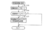
また、CPU56は、特別図柄プロセスフラグの値に応じて特別図柄の演出表示を行うための特別図柄表示制御データを特別図柄表示制御データ設定用の出力バッファに設定する特別図柄表示制御処理を行う(ステップS32)。CPU56は、例えば、特別図柄プロセス処理でセットされる開始フラグがセットされると終了フラグがセットされるまで、変動速度が1コマ/0.2秒であれば、0.2秒が経過する毎に、出力バッファに設定される表示制御データの値を+1する。また、CPU56は、出力バッファに設定された表示制御データに応じて、ステップS22において駆動信号を出力することによって、第1特別図柄表示器8aおよび第2特別図柄表示器8bにおける第1特別図柄および第2特別図柄の可変表示を実行する。
Further, the
さらに、CPU56は、普通図柄プロセスフラグの値に応じて普通図柄の演出表示を行うための普通図柄表示制御データを普通図柄表示制御データ設定用の出力バッファに設定する普通図柄表示制御処理を行う(ステップS33)。CPU56は、例えば、普通図柄の変動に関する開始フラグがセットされると終了フラグがセットされるまで、普通図柄の変動速度が0.2秒ごとに表示状態(「○」および「×」)を切り替えるような速度であれば、0.2秒が経過する毎に、出力バッファに設定される表示制御データの値(例えば、「○」を示す1と「×」を示す0)を切り替える。また、CPU56は、出力バッファに設定された表示制御データに応じて、ステップS22において駆動信号を出力することによって、普通図柄表示器10における普通図柄の演出表示を実行する。
Further, the
その後、割込許可状態に設定し(ステップS34)、処理を終了する。 Thereafter, the interrupt permission state is set (step S34), and the process is terminated.
以上の制御によって、この実施の形態では、遊技制御処理は2ms毎に起動されることになる。なお、遊技制御処理は、タイマ割込処理におけるステップS21〜S33(ステップS29を除く。)の処理に相当する。また、この実施の形態では、タイマ割込処理で遊技制御処理が実行されているが、タイマ割込処理では例えば割込が発生したことを示すフラグのセットのみがなされ、遊技制御処理はメイン処理において実行されるようにしてもよい。 With the above control, in this embodiment, the game control process is started every 2 ms. The game control process corresponds to the processes in steps S21 to S33 (excluding step S29) in the timer interrupt process. In this embodiment, the game control process is executed by the timer interrupt process. However, in the timer interrupt process, for example, only a flag indicating that an interrupt has occurred is set, and the game control process is performed by the main process. May be executed.
この実施の形態では、演出図柄の可変表示中には、リーチ演出とは異なり、演出図柄の可変表示状態がリーチ状態となる可能性があることや、可変表示結果が「大当り」となる可能性があることを、演出図柄の可変表示態様などにより遊技者に報知するための特定演出が実行されることがある。この実施の形態では、「滑り」、「擬似連」、「イントロ」、「発展チャンス目」、「発展チャンス目終了」といった特定演出が実行可能に設定されている。 In this embodiment, during the variable display of the production symbol, unlike the reach production, the variable display state of the production symbol may become the reach state, and the variable display result may be “big hit” There is a case where a specific effect for informing the player that there is a variable display mode of the effect symbol is executed. In this embodiment, specific effects such as “sliding”, “pseudo-continuous”, “intro”, “development opportunity”, and “end of development opportunity” are set to be executable.
「滑り」の特定演出では、「左」、「中」、「右」の演出図柄表示エリア9L、9C、9Rにおける全部にて演出図柄を変動させてから、2つ以上の演出図柄表示エリア(例えば「左」及び「右」の演出図柄表示エリア9L、9Rなど)にて演出図柄を仮停止表示させた後、その仮停止表示した演出図柄表示エリアのうち所定数(例えば「1」または「2」)の演出図柄表示エリア(例えば「左」の演出図柄表示エリア9Lと「右」の演出図柄表示エリア9Rのいずれか一方または双方)にて演出図柄を再び変動させた後に停止表示させることで、停止表示する演出図柄を変更させる演出表示が行われる。ここで、仮停止表示とは、後述する複数種類の変動パターン毎に定められた変動時間が経過したことにより、確定演出図柄が停止表示(最終停止表示)される以前に行われる演出図柄の停止表示をいう。なお、仮停止表示では、演出図柄が停留して表示される一方で、例えば揺れ変動表示を行うことや短時間の停留だけで直ちに演出図柄を再変動させることなどによって、遊技者に停止表示された演出図柄が確定しない旨を報知すればよい。あるいは、仮停止表示でも、停止表示された演出図柄が確定したと遊技者が認識する程度に演出図柄を停留させてから、演出図柄を再変動させるようにしてもよい。
In the “slip” specific effect, the effect symbols are changed in all of the “left”, “middle”, and “right” effect
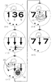
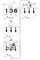
「擬似連」の特定演出では、特図ゲームの第1開始条件と第2開始条件のいずれか一方が1回成立したことに基づき、「左」、「中」、「右」の演出図柄表示エリア9L、9C、9Rにおける全部にて演出図柄を変動させてから、全部の演出図柄表示エリア9L、9C、9Rにて演出図柄を仮停止表示させた後、全部の演出図柄表示エリア9L、9C、9Rにて演出図柄を再び変動(擬似連変動)させる演出表示を、所定回(例えば最大3回まで)行うことができる。一例として、「擬似連」の特定演出では、「左」、「中」、「右」の演出図柄表示エリア9L、9C、9Rにて、図7(A)に示す擬似連チャンス目GC1〜GC8のいずれかを構成する演出図柄が仮停止表示される。ここで、「左図柄」は「左」の演出図柄表示エリア9Lに表示(停止表示または仮停止表示)される演出図柄であり、「中図柄」は「中」の演出図柄表示エリア9Cに表示される演出図柄であり、「右図柄」は「右」の演出図柄表示エリア9Rに表示される演出図柄である。なお、擬似連チャンス目GC1〜GC8は、特殊組合せに含まれる演出図柄の組合せとして、予め定められていればよい。
In the “pseudo-ream” specific effect, “left”, “middle”, and “right” effect symbols are displayed based on the fact that one of the first start condition and the second start condition of the special game is established once. After changing the effect symbols in all of the
「イントロ」の特定演出では、「左」、「中」、「右」の各演出図柄表示エリア9L、9C、9Rにおける全部にて演出図柄を変動させてから、全部の演出図柄表示エリア9L、9C、9Rにて確定演出図柄が停止表示(最終停止表示)される以前に、例えばリーチ演出にて行われる演出表示の導入部分といった、所定の演出表示が行われる。
In the specific effect of “Intro”, the effect symbols are changed in all the effect
「発展チャンス目」の特定演出では、「左」、「中」、「右」の各演出図柄表示エリア9L、9C、9Rにおける全部にて演出図柄を変動させてから、全部の演出図柄表示エリア9L、9C、9Rにて、予め定められた特殊組合せに含まれる発展チャンス目を構成する演出図柄を仮停止表示させた後、演出図柄の可変表示状態をリーチ状態として所定のリーチ演出が開始される。一例として、「発展チャンス目」の特定演出では、「左」、「中」、「右」の演出図柄表示エリア9L、9C、9Rにて、図7(B)に示す発展チャンス目HC1〜HC8のいずれかを構成する演出図柄が仮停止表示される。そのため、発展チャンス目HC1〜HC8のいずれかが仮停止表示されることにより、演出図柄の可変表示状態がリーチ状態となることや、リーチ状態となった後に可変表示結果が「大当り」となることに対する、遊技者の期待感が高められる。
In the specific effect of “Development Opportunity”, the effect
「発展チャンス目終了」の特定演出では、「左」、「中」、「右」の各演出図柄表示エリア9L、9C、9Rにおける全部にて演出図柄を変動させてから、全部の演出図柄表示エリア9L、9C、9Rにて、発展チャンス目として予め定められた組合せの演出図柄を、確定演出図柄として停止表示(最終停止表示)させる演出表示が行われる。一例として、「発展チャンス目終了」の特定演出では、「発展チャンス目」の特定演出で仮停止表示される発展チャンス目HC1〜HC8のいずれかが、確定演出図柄として停止表示される。
In the specific effect of “end of development chance”, the effect symbols are changed in all the effect
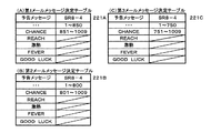
さらに、演出図柄の可変表示中には、リーチ演出や特定演出とは異なり、例えば所定のキャラクタ画像やメッセージ画像を表示することなどといった、演出図柄の可変表示態様以外の表示態様により、演出図柄の可変表示状態がリーチ状態となる可能性があることや、可変表示結果が「大当り」となる可能性があることを、遊技者に報知するための予告演出が実行されることがある。この実施の形態では、「ステップアップ予告」、「メール表示」といった予告演出が実行可能に設定されている。 In addition, during the variable display of the production symbol, unlike the reach production and the specific production, for example, by displaying other than the variable display mode of the production symbol, such as displaying a predetermined character image or message image, A notice effect may be executed to notify the player that the variable display state may become a reach state and that the variable display result may be a “hit”. In this embodiment, a notice effect such as “step-up notice” and “mail display” is set to be executable.
「ステップアップ予告」の予告演出では、「左」、「中」、「右」の各演出図柄表示エリア9L、9C、9Rにおける全部にて演出図柄を変動させてから、2つ以上の演出図柄表示エリアにて演出図柄を仮停止表示させる以前に、演出表示装置9の表示領域にて、予め用意された複数種類の演出画像を所定の順番に従って切り替えて表示させる演出表示が行われることがある。なお、「ステップアップ予告」の予告演出では、予め用意された複数種類の演出画像のうちいずれか1つ(例えば所定の順番において最初に表示される演出画像など)が表示された後、演出画像が切り替えられることなく、予告演出における演出表示を終了させることがあるようにしてもよい。
In the “step-up notice” notice effect, the effect symbols are changed in all the effect
「メール表示」の予告演出では、「左」、「中」、「右」の各演出図柄表示エリア9L、9C、9Rにおける全部にて演出図柄を変動させてから、2つ以上の演出図柄表示エリアにて演出図柄を仮停止表示させる以前に、遊技者により操作ボタン120が操作されたことに応じて、例えば演出表示装置9の表示領域における演出画像の表示を変更させるといった、演出動作が変化する演出表示が行われる。
In the “mail display” notice effect, the effect symbols are changed in all of the effect
特図ゲームにおける確定特別図柄として、ハズレ図柄となる特別図柄が停止表示される場合には、演出図柄の可変表示が開始されてから、演出図柄の可変表示状態がリーチ状態とならずに、所定の非リーチ組合せとなる確定演出図柄、あるいは、特殊組合せのうち発展チャンス目HC1〜HC8のいずれかとなる確定演出図柄が、停止表示されることがある。このような演出図柄の可変表示態様は、可変表示結果が「ハズレ」となる場合における「非リーチ」(「通常ハズレ」ともいう)の可変表示態様と称される。 When a special symbol that becomes a lost symbol is stopped and displayed as a confirmed special symbol in the special symbol game, after the variable display of the production symbol is started, the variable display state of the production symbol does not become the reach state, but the predetermined design. There is a case where the confirmed effect symbol that becomes one of the development chances HC1 to HC8 in the special combination is stopped and displayed. Such a variable display mode of the effect symbol is referred to as a “non-reach” (also referred to as “normal loss”) variable display mode when the variable display result is “losing”.
特図ゲームにおける確定特別図柄として、ハズレ図柄となる特別図柄が停止表示される場合には、演出図柄の可変表示が開始されてから、演出図柄の可変表示状態がリーチ状態となったことに対応して、リーチ演出が実行された後に、所定のリーチハズレ組合せとなる確定演出図柄が停止表示されることがある。このような演出図柄の可変表示結果は、可変表示結果が「ハズレ」となる場合における「リーチ」(「リーチハズレ」ともいう)の可変表示態様と称される。 When a special symbol that becomes a losing symbol is stopped and displayed as a confirmed special symbol in the special symbol game, it corresponds to the fact that the variable symbol display state has reached the reach state after the variable symbol symbol display has started. Then, after the reach effect is executed, the confirmed effect symbol that becomes a predetermined reach-losing combination may be stopped and displayed. Such a variable display result of the effect symbol is referred to as a variable display mode of “reach” (also referred to as “reach lose”) when the variable display result is “losing”.
特図ゲームにおける確定特別図柄として、15ラウンド大当り図柄となる特別図柄のうち通常大当り図柄が停止表示される場合には、演出図柄の可変表示状態がリーチ状態となったことに対応して、所定のリーチ演出が実行された後に、所定の通常大当り組合せとなる確定演出図柄が停止表示される。ここで、通常大当り組合せとなる確定演出図柄は、例えば演出表示装置9における「左」、「中」、「右」の各演出図柄表示エリア9L、9C、9Rにて可変表示される図柄番号が「1」〜「8」の演出図柄のうち、図柄番号が偶数「2」、「4」、「6」、「8」である演出図柄のいずれか1つが、「左」、「中」、「右」の各演出図柄表示エリア9L、9C、9Rにて所定の有効ライン上に揃って停止表示されるものであればよい。このように通常大当り組合せを構成する図柄番号が偶数「2」、「4」、「6」、「8」である演出図柄は、通常図柄(「非確変図柄」ともいう)と称される。そして、特図ゲームにおける確定特別図柄が通常大当り図柄となることに対応して、所定のリーチ演出が実行された後に、通常大当り組合せの確定演出図柄が停止表示される演出図柄の可変表示態様は、可変表示結果が「大当り」となる場合における「通常」(「通常大当り」ともいう)の可変表示態様と称される。こうして「通常」の可変表示態様により可変表示結果が「大当り」となった後には、15ラウンド大当り状態に制御され、その15ラウンド大当り状態が終了すると、時短状態または通常状態に制御されることになる。
When the special big win symbol is stopped and displayed as a special symbol that becomes a 15-round big hit symbol as a confirmed special symbol in the special symbol game, a predetermined display corresponding to the fact that the variable display state of the production symbol has reached the reach state After the reach effect is executed, the determined effect symbol that is a predetermined normal jackpot combination is stopped and displayed. Here, the confirmed effect symbol which is a normal big hit combination is, for example, a symbol number variably displayed in each of the effect
特図ゲームにおける確定特別図柄として、15ラウンド大当り図柄となる特別図柄のうち確変大当り図柄が停止表示される場合には、演出図柄の可変表示状態がリーチ状態となったことに対応して、演出図柄の可変表示態様が「通常」である場合と同様のリーチ演出が実行された後に、所定の確変大当り組合せとなる確定演出図柄が停止表示されることがある。ここで、確変大当り組合せとなる確定演出図柄は、例えば演出表示装置9における「左」、「中」、「右」の各演出図柄表示エリア9L、9C、9Rにて可変表示される図柄番号が「1」〜「8」の演出図柄のうち、図柄番号が奇数「1」、「3」、「5」、「7」である演出図柄のいずれか1つが、「左」、「中」、「右」の各演出図柄表示エリア9L、9C、9Rにて所定の有効ライン上に揃って停止表示されるものであればよい。このように確変大当り組合せを構成する図柄番号が奇数「1」、「3」、「5」、「7」である演出図柄は、確変図柄と称される。そして、特図ゲームにおける確定特別図柄が確変大当り図柄となることに対応して、演出図柄の可変表示態様が「通常」である場合と同様のリーチ演出が実行された後に、確変大当り組合せの確定演出図柄が停止表示される演出図柄の可変表示態様は、可変表示結果が「大当り」となる場合における「第1確変」の可変表示態様と称される。こうして「第1確変」の可変表示態様により可変表示結果が「大当り」となった後には、15ラウンド大当り状態に制御され、その15ラウンド大当り状態が終了すると、確変状態に制御されることになる。
As a confirmed special symbol in the special symbol game, if the probability variable big-hit symbol is stopped and displayed among the special symbols that become the 15-round big-hit symbol, the production symbol is displayed in correspondence with the variable display state becoming the reach state. After the reach effect similar to the case where the variable display mode of the symbol is “normal” is executed, the confirmed effect symbol that becomes a predetermined probability variation big hit combination may be stopped and displayed. Here, the confirmed effect symbol that is a probable big hit combination is, for example, a symbol number that is variably displayed in each of the effect
特図ゲームにおける確定特別図柄として、15ラウンド大当り図柄となる特別図柄のうち確変大当り図柄が停止表示される場合には、演出図柄の可変表示状態がリーチ状態となったことに対応して、可変表示態様が「通常」である場合とは異なるリーチ演出が実行された後に、所定の確変大当り組合せとなる確定演出図柄が停止表示されることがある。このように特図ゲームにおける確定特別図柄が確変大当り図柄となることに対応して、演出図柄の可変表示態様が「通常」である場合とは異なるリーチ演出が実行された後に、確変大当り組合せの確定演出図柄が停止表示される演出図柄の可変表示態様は、可変表示結果が「大当り」となる場合における「第2確変」の可変表示態様と称される。こうして「第2確変」の可変表示態様により可変表示結果が「大当り」となった後には、15ラウンド大当り状態に制御され、その15ラウンド大当り状態が終了すると、確変状態に制御されることになる。 As a confirmed special symbol in the special symbol game, when the probability variable big hit symbol is stopped and displayed among the special symbols that become the 15 round big hit symbol, the variable display state of the production symbol is changed corresponding to the reach state. After a reach effect different from the case where the display mode is “normal” is executed, a confirmed effect symbol that is a predetermined probability variation jackpot combination may be stopped and displayed. In this way, in response to the confirmed special symbol in the special figure game becoming a probable big hit symbol, after a reach production different from the case where the variable display mode of the production symbol is “normal” is executed, The variable display mode of the production symbol in which the finalized design symbol is stopped and displayed is referred to as a “second probability variation” variable display mode when the variable display result is “big hit”. Thus, after the variable display result is “big hit” by the variable display mode of “second positive change”, the control is made to the 15 round big hit state, and when the 15 round big hit state is finished, the variable change state is controlled to the positive change state. .
特図ゲームにおける確定特別図柄として、15ラウンド大当り図柄となる特別図柄のうち確変大当り図柄が停止表示される場合には、演出図柄の可変表示状態がリーチ状態となったことに対応して、演出図柄の可変表示態様が「通常」である場合と同様のリーチ演出が実行された後に、通常大当り組合せの確定演出図柄が停止表示されることがある。このように特図ゲームにおける確定特別図柄が確変大当り図柄となることに対応して、演出図柄の可変表示態様が「通常」である場合と同様のリーチ演出が実行された後に、通常大当り組合せの確定演出図柄が停止表示される演出図柄の可変表示態様は、可変表示結果が「大当り」となる場合における「第3確変」の可変表示態様と称される。こうして「第3確変」の可変表示態様により可変表示結果が「大当り」となった後には、15ラウンド大当り状態に制御され、その15ラウンド大当り状態が終了すると、確変状態に制御されることになる。 As a confirmed special symbol in the special symbol game, if the probability variable big-hit symbol is stopped and displayed among the special symbols that become the 15-round big-hit symbol, the production symbol is displayed in correspondence with the variable display state becoming the reach state. After the reach effect similar to the case where the variable display mode of the symbol is “normal” is executed, the fixed effect symbol of the normal jackpot combination may be stopped and displayed. In this way, in response to the confirmed special symbol in the special figure game becoming a probable big hit symbol, after the reach production similar to the case where the variable display mode of the production symbol is “normal” is executed, The variable display mode of the effect symbol in which the confirmed effect symbol is stopped and displayed is referred to as a “third probability change” variable display mode when the variable display result is “big hit”. Thus, after the variable display result is “big hit” by the variable display mode of “third probability change”, the game is controlled to the 15 round big hit state, and when the 15 round big hit state is finished, it is controlled to the positive change state. .
このように、演出図柄の可変表示態様が「第1確変」や「第2確変」となる場合には、演出図柄の可変表示にて確変大当り組合せとなる確定演出図柄が停止表示されることで、15ラウンド大当り状態に制御された後に確変状態となることが確定する。その一方で、演出図柄の可変表示態様が「第3確変」となる場合には、可変表示態様が「通常」となる場合と同様に、演出図柄の可変表示にて通常大当り組合せとなる確定演出図柄が停止表示される。そのため、可変表示態様が「第3確変」となる場合には、確変状態となるか否かを、演出図柄の可変表示結果からは遊技者が認識することはできない。すなわち、確変大当り組合せとなる確定演出図柄は、大当り遊技状態に制御されることが確定する特定表示結果に含まれるとともに、確変状態に制御されることが確定する特別表示結果に含まれる。その一方で、通常大当り組合せとなる確定演出図柄は、確変状態に制御されることが確定しない特別表示結果以外の特定表示結果に含まれる。 As described above, when the variable display mode of the effect symbol is “first probability variation” or “second probability variation”, the confirmed effect symbol that is a probability variation big hit combination is stopped and displayed by variable display of the effect symbol. , It is determined that the probability change state is reached after being controlled to the 15 round big hit state. On the other hand, when the variable display mode of the effect symbol is “third probability variation”, the final effect that is a normal jackpot combination in the variable display of the effect symbol is the same as when the variable display mode is “normal”. The symbol is stopped and displayed. For this reason, when the variable display mode is “third probability variation”, the player cannot recognize whether or not the probability variation state is obtained from the variable display result of the effect symbol. In other words, the confirmed effect symbol that becomes the probability variation jackpot combination is included in the specific display result that is determined to be controlled to the jackpot gaming state, and is included in the special display result that is determined to be controlled to the probability variation state. On the other hand, the confirmed effect symbol that is a normal jackpot combination is included in the specific display result other than the special display result that is not determined to be controlled to the probability variation state.
特図ゲームにおける確定特別図柄として、15ラウンド大当り図柄となる特別図柄のうち確変大当り図柄が停止表示される場合には、演出図柄の可変表示状態がリーチ状態となったことに対応して「ノーマル」のリーチ演出及びルーレットチャンス演出が実行された後に、所定のリーチハズレ組合せとなる確定演出図柄が停止表示されること、あるいは、「擬似連」の特定演出が実行された後に、所定の非リーチ組合せとなる確定演出図柄が停止表示されること、あるいは、演出図柄の可変表示状態がリーチ状態とならずに、各種確定演出図柄が停止表示されることがある。なお、突確チャンス目TC1〜TC4は、特殊組合せに含まれる演出図柄の組合せとして、予め定められていればよい。このように特図ゲームにおける確定特別図柄が確変大当り図柄となることに対応して、リーチ状態とならずに、図7(C)に示す突確チャンス目TC1〜TC4のいずれかとなる確定演出図柄が停止表示される演出図柄の可変表示態様は、可変表示結果が「大当り」となる場合における「第4確変」の可変表示態様と称される。こうして「第4確変」の可変表示態様により可変表示結果が「大当り」となった後には、突確見せ掛け15ラウンド大当り状態に制御され、その突確見せ掛け15ラウンド大当り状態が終了すると、確変状態に制御されることになる。
In the special figure game, if the probability variable big win symbol is stopped and displayed among the special symbols that become the 15 round big hit symbol, the variable symbol display state of the production symbol is changed to the reach state. After the reach effect and the roulette chance effect are executed, the predetermined effect pattern that is the predetermined reach-losing combination is stopped or displayed, or after the specific effect of the “pseudo-continuous” is executed, the predetermined non-reach combination May be displayed in a stopped state, or the variable display state of the effect symbol may not be in the reach state, and various confirmed effect symbols may be displayed in a stopped state. Note that the chances of success TC <b> 1 to TC <b> 4 may be determined in advance as a combination of effect symbols included in the special combination. Corresponding to the fact that the confirmed special symbol in the special figure game becomes a probable big hit symbol, the confirmed effect symbol that becomes one of the chance chance items TC1 to TC4 shown in FIG. The variable display mode of the effect symbol that is stopped and displayed is referred to as a “fourth probability variation” variable display mode when the variable display result is “big hit”. Thus, after the variable display result is “big hit” by the variable display mode of “fourth probability change”, it is controlled to the
特図ゲームにおける確定特別図柄として、2ラウンド大当り図柄となる「1」の数字を示す特別図柄が停止表示される場合には、演出図柄の可変表示状態がリーチ状態となったことに対応して「ノーマル」のリーチ演出が実行された後に、あるいは、「ノーマル」のリーチ演出及びルーレットチャンス演出が実行された後に、所定のリーチハズレ組合せとなる確定演出図柄が停止表示されること、「擬似連」の特定演出が実行された後に、あるいは、「擬似連」の特定演出が実行されることなく、所定の非リーチ組合せとなる確定演出図柄が停止表示されること、あるいは、演出図柄の可変表示状態がリーチ状態とならずに、図7(B)に示す発展チャンス目HC1〜HC8のいずれかとなる確定演出図柄が停止表示されること、あるいは、図7(C)に示す突確チャンス目TC1〜TC4のいずれかとなる確定演出図柄が停止表示されることがある。なお、突確チャンス目TC1〜TC4は、特殊組合せに含まれる演出図柄の組合せとして、予め定められていればよい。このように特図ゲームにおける確定特別図柄が2ラウンド大当り図柄である「1」の数字を示す特別図柄となることに対応して、各種の確定演出図柄が停止表示される演出図柄の可変表示態様は、可変表示結果が「大当り」となる場合における「突確」(「突確大当り」あるいは「突然確変大当り」ともいう)の可変表示態様と称される。こうして「突確」の可変表示態様により可変表示結果が「大当り」となった後には、2ラウンド大当り状態に制御され、その2ラウンド大当り状態が終了すると、確変状態に制御されることになる。 When the special symbol indicating the number of “1”, which is a two-round jackpot symbol, is stopped and displayed as a confirmed special symbol in the special symbol game, the variable symbol display state of the production symbol corresponds to the reach state. After the “normal” reach effect is executed, or after the “normal” reach effect and roulette chance effect are executed, the fixed effect symbol that is the predetermined reach lose combination is stopped and displayed, After the specific effect is executed, or the specific effect of the “pseudo-continuous” is not executed, the fixed effect symbol that becomes a predetermined non-reach combination is stopped or displayed, or the variable display state of the effect symbol Is not reached, and the finalized design symbol that is one of the development chances HC1 to HC8 shown in FIG. 7 determined performance symbol to be one of 突確 chance th TC1~TC4 shown in (C) may appear stopped. Note that the chances of success TC <b> 1 to TC <b> 4 may be determined in advance as a combination of effect symbols included in the special combination. In this way, in response to the confirmed special symbol in the special symbol game becoming a special symbol indicating the number “1”, which is a two-round jackpot symbol, the variable display mode of the effect symbols in which various confirmed effect symbols are stopped and displayed. Is referred to as a variable display mode of “surprise accuracy” (also referred to as “surprise accuracy hit” or “sudden probability change big hit”) when the variable display result is “big hit”. Thus, after the variable display result is “big hit” by the variable display mode of “surprise accuracy”, it is controlled to the two round big hit state, and when the two round big hit state is finished, it is controlled to the probability changing state.
このように、演出図柄の可変表示態様が「第4確変」となる場合には、図7(C)に示す突確チャンス目TC1〜TC4のいずれかとなる確定演出図柄が停止表示されること、「ノーマル」のリーチ演出及びルーレットチャンス演出が実行された後に所定のリーチハズレ組合せとなる確定演出図柄が停止表示されること、「擬似連」の特定演出が実行された後に所定の非リーチ組合せとなる確定演出図柄が停止表示されることがある。また、演出図柄の可変表示態様が「突確」となる場合には、突確チャンス目TC1〜TC4のいずれかとなる確定演出図柄が停止表示されること、「ノーマル」のリーチ演出及びルーレットチャンス演出が実行された後に所定のリーチハズレ組合せとなる確定演出図柄が停止表示されること、「擬似連」の特定演出が実行された後に所定の非リーチ組合せとなる確定演出図柄が停止表示されることがある。そのため、演出図柄の可変表示にて突確チャンス目TC1〜TC4のいずれかとなる確定演出図柄が停止表示された場合や、「ノーマル」のリーチ演出及びルーレットチャンス演出が実行された後に所定のリーチハズレ組合せとなる確定演出図柄が停止表示された場合、「擬似連」の特定演出が実行された後に所定の非リーチ組合せとなる確定演出図柄が停止表示された場合には、突確見せ掛け15ラウンド大当り状態に制御されるか2ラウンド大当り状態に制御されるかを演出図柄の可変表示結果からは遊技者が認識することができない。
As described above, when the variable display mode of the effect symbol is “fourth probability variation”, the confirmed effect symbol that is one of the probability chance items TC1 to TC4 shown in FIG. After a “normal” reach effect and a roulette chance effect are executed, a confirmed effect pattern that is a predetermined reach-losing combination is stopped and displayed, and after a “pseudo-continuous” specific effect is executed, a predetermined non-reach combination is confirmed The effect design may be stopped and displayed. In addition, when the variable display mode of the effect symbol is “accuracy”, the definite effect symbol that is one of the accuracy chance items TC1 to TC4 is stopped and displayed, and the “normal” reach effect and the roulette chance effect are executed. In some cases, a confirmed effect design that becomes a predetermined reach-losing combination is stopped and displayed, and a specific effect design that becomes a predetermined non-reach combination is stopped and displayed after the “pseudo-continuous” specific effect is executed. For this reason, when a fixed effect symbol that is one of the chance chance items TC1 to TC4 is stopped and displayed in a variable display of the effect symbol, or after a “normal” reach effect and a roulette chance effect are executed, a predetermined reach lose combination If the confirmed effect symbol that is a predetermined non-reach combination is stopped and displayed after the specific effect of “pseudo-continuous” is executed, the game is controlled to a
ここで、図7(C)に示す突確チャンス目TC1〜TC4のいずれかとなる確定演出図柄は、演出図柄の可変表示態様が「突確」及び「第4確変」となる場合に限り停止表示される。すなわち、演出図柄の可変表示にて突確チャンス目TC1〜TC4のいずれかとなる確定演出図柄が停止表示された場合には、「突確」又は「第4確変」の可変表示態様により可変表示結果が「大当り」となることが確定する。 Here, the confirmed effect symbol that is one of the odd chance items TC1 to TC4 shown in FIG. 7C is stopped and displayed only when the variable display mode of the effect symbol is “surprise” and “fourth probability change”. . In other words, when the finalized design symbol that is one of the chance chance items TC1 to TC4 is stopped and displayed in the variable display of the production symbol, the variable display result is “ It will be decided that it will be a big hit.
可変表示結果が「大当り」となる場合における演出図柄の可変表示態様が「通常」、「第1確変」、「第3確変」のいずれかである場合には、演出図柄の可変表示中に、特定変動表示としての変動中昇格演出が実行されることがある。変動中昇格演出では、演出表示装置9における「左」、「中」、「右」の各演出図柄表示エリア9L、9C、9Rの有効ライン上に通常大当り組合せとなる演出図柄を仮停止表示させた後に、例えば「左」、「中」、「右」の各演出図柄表示エリア9L、9C、9Rにて同一の演出図柄が揃った状態で再び変動させ、確変大当り組合せとなる演出図柄と、通常大当り組合せとなる演出図柄のうちいずれかを、確定演出図柄として停止表示(最終停止表示)させる。ここで、演出図柄の可変表示態様が「通常」や「第3確変」であることに対応して変動中昇格演出が実行される場合には、その変動中昇格演出として、仮停止表示させた演出図柄を再変動させた後に通常大当り組合せとなる確定演出図柄を停止表示する変動中昇格失敗演出が行われる。これに対して、可変表示態様が「第1確変」であることに対応して変動中昇格演出が実行される場合には、その変動中昇格演出として、仮停止表示させた演出図柄を再変動させた後に確変大当り組合せとなる確定演出図柄を停止表示する変動中昇格成功演出が行われる。
When the variable display mode of the effect symbol when the variable display result is “big hit” is any one of “normal”, “first probability variation”, and “third probability variation”, during the variable display of the effect symbol, There is a case where a promotion effect during change as a specific change display is executed. In the fluctuating promotion effect, the effect symbol which is normally a big hit combination is temporarily stopped and displayed on the effective lines of the effect
可変表示結果が「大当り」となる場合における演出図柄の可変表示態様が「通常」と「第3確変」のいずれかである場合には、可変表示結果が停止表示されてから、15ラウンド大当り状態に制御された後、その15ラウンド大当り状態が終了するまでの期間にて、確変状態に制御するか否かの報知演出としての大当り中昇格演出が実行される。ここで、大当り中昇格演出が実行されるタイミングは、可変表示結果が停止表示されてから、15ラウンド大当り状態における最初のラウンドが開始される以前の期間であってもよいし、15ラウンド大当り状態においていずれかのラウンドが実行中の期間であってもよいし、15ラウンド大当り状態においていずれかのラウンドが終了してから次のラウンドが開始されるまでの期間であってもよいし、15ラウンド大当り状態において最終のラウンドが終了してから、次の可変表示ゲームが開始されるまでの期間であってもよい。あるいは、15ラウンド大当り状態の終了後における最初の特別図柄や演出図柄の変動中に、大当り中昇格演出に相当する演出動作が行われるようにしてもよい。15ラウンド大当り状態において最終のラウンドが終了してから実行される大当り中昇格演出を、特に「エンディング昇格演出」ということもある。 When the variable display result of the variable display result is “big hit”, if the variable display mode of the effect symbol is “normal” or “third probability change”, the variable display result is stopped and displayed for 15 rounds of big hit status After the control, the jackpot promotion effect is executed as a notification effect as to whether or not to control to the probable change state during the period until the 15 round big hit state is finished. Here, the timing at which the jackpot promotion effect is executed may be a period before the start of the first round in the 15 round big hit state after the variable display result is stopped and displayed, or the 15 round big hit state May be a period during which any one of the rounds is being executed, or may be a period from the end of any round to the start of the next round in the 15 round big hit state, or 15 rounds. It may be a period from the end of the last round in the big hit state to the start of the next variable display game. Alternatively, an effect operation corresponding to the promotion effect during the big hit may be performed during the fluctuation of the first special symbol or effect symbol after the end of the 15th round big hit state. The jackpot promotion effect executed after the final round in the 15 round jackpot state is sometimes referred to as “ending promotion effect” in particular.
大当り中昇格演出には、確定演出図柄が通常大当り組合せであるにもかかわらず遊技状態が確変状態となる昇格がある旨を報知する大当り中昇格成功演出と、確変状態となる昇格がない旨を報知する大当り中昇格失敗演出とがある。一例として、大当り中昇格演出では、演出表示装置9の表示領域にて演出図柄を可変表示させ、通常図柄と、確変図柄のうちいずれかを、演出表示結果として停止表示させる。このとき、大当り中昇格失敗演出では通常図柄を演出表示結果として停止表示させる一方、大当り中昇格成功演出では確変図柄を演出表示結果として停止表示させればよい。他の一例として、大当り中昇格演出では、演出表示装置9の表示領域にてルーレットゲームを示す演出画像の表示を行う。このとき、大当り中昇格失敗演出では回転するルーレットに投入されたボールが「偶数」に入って「残念!」という演出画像の表示を行う一方、大当り中昇格成功演出では回転するルーレットに投入されたボールが「奇数」に入って「確変!」という演出画像の表示を行う。特図ゲームにおける確定特別図柄として「7」の数字を示す特別図柄が停止表示されることに対応して、「第3確変」の可変表示態様により可変表示結果が「大当り」となった後には、大当り遊技状態が終了するまでに、大当り中昇格成功演出を実行することにより、確変状態となる昇格がある旨を報知する。特図ゲームにおける確定特別図柄として「3」の数字を示す特別図柄が停止表示されることに対応して、「通常」の可変表示態様により可変表示結果が「大当り」となった後には、大当り遊技状態が終了するまでに、大当り中昇格成功演出を実行せず、確変状態となる昇格がある旨の報知は行われない。
In the jackpot promotion effect, there is a jackpot promotion promotion effect that informs that there is a promotion that the game state becomes a probable change state even though the confirmed effect pattern is usually a jackpot combination, and that there is no promotion that becomes a probable change state There is a promotion promotion failure during the jackpot to be notified. As an example, in the jackpot promotion effect, the effect symbol is variably displayed in the display area of the
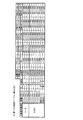
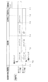
図8は、可変表示結果が「ハズレ」となる場合における演出図柄の可変表示態様が「非リーチ」である場合と「リーチ」である場合のそれぞれに対応して予め用意された演出図柄の変動パターンを例示する説明図である。図8に示すように、この実施の形態では、演出図柄の可変表示態様が「非リーチ」である場合に対応した変動パターンとして、非リーチPA1−1〜非リーチPA1−7、非リーチPB1−1及び非リーチPB1−2、非リーチPC1−1及び非リーチPC1−2の変動パターンが用意されている。また、演出図柄の可変表示態様が「リーチ」である場合に対応した変動パターンとして、ノーマルPA2−1〜ノーマルPA2−4、スーパーPA3−1〜スーパーPA3−10、スーパーPB3−1〜スーパーPB3−6、スーパーPC3−1〜スーパーPC3−4の変動パターンが用意されている。 FIG. 8 is a diagram showing variations in the presentation symbols prepared in advance corresponding to the cases where the variable display mode of the presentation symbol is “non-reach” and “reach” when the variable display result is “losing”. It is explanatory drawing which illustrates a pattern. As shown in FIG. 8, in this embodiment, non-reach PA1-1 to non-reach PA1-7 and non-reach PB1- are used as the variation patterns corresponding to the case where the variable display mode of the effect symbol is “non-reach”. 1 and non-reach PB1-2, non-reach PC1-1 and non-reach PC1-2 variation patterns are prepared. In addition, as variation patterns corresponding to the case where the variable display mode of the production symbol is “reach”, normal PA2-1 to normal PA2-4, super PA3-1 to super PA3-10, super PB3-1 to super PB3— 6. Variation patterns of Super PC 3-1 to Super PC 3-4 are prepared.
図9は、可変表示結果が「大当り」となる場合に対応して予め用意された演出図柄の変動パターンを例示する説明図である。図9に示すように、この実施の形態では、演出図柄の可変表示結果が「大当り」である場合に対応した変動パターンとして、ノーマルPA2−5〜ノーマルPA2−8、スーパーPA4−1〜スーパーPA4−10、スーパーPA5−1〜スーパーPA5−5、スーパーPB4−1〜スーパーPB4−5、スーパーPB5−1〜スーパーPB5−5、スーパーPC4−1及びスーパーPC4−2、スーパーPD1−1及びスーパーPD1−2、スーパーPE1−1及びスーパーPE1−2、スーパーPF1−1〜スーパーPF1−3、特殊PG1−1〜特殊PG1−6、特殊PG2−1、特殊PG2−2、特殊PG3−1〜特殊PG3−3、特殊PH1−3〜特殊PH1−5、特殊PH3−1〜特殊PH3−3の変動パターンが用意されている。 FIG. 9 is an explanatory diagram exemplifying a variation pattern of the effect symbol prepared in advance corresponding to the case where the variable display result is “big hit”. As shown in FIG. 9, in this embodiment, normal PA2-5 to normal PA2-8, super PA4-1 to super PA4 are used as the variation patterns corresponding to the case where the variable display result of the effect symbol is “big hit”. -10, Super PA5-1 to Super PA5-5, Super PB4-1 to Super PB4-5, Super PB5-1 to Super PB5-5, Super PC4-1 and Super PC4-2, Super PD1-1 and Super PD1 -2, Super PE1-1 and Super PE1-2, Super PF1-1 to Super PF1-3, Special PG1-1 to Special PG1-6, Special PG2-1, Special PG2-2, Special PG3-1 to Special PG3 -3, special PH1-3 to special PH1-5, special PH3-1 to special PH3-3 variation patterns are available .
図2に示す遊技制御用マイクロコンピュータ560が備えるROMには、ゲーム制御用のプログラムの他にも、遊技の進行を制御するために用いられる各種のデータテーブルなどが格納されている。例えば、ROMには、CPU103が各種の判定や決定を行うために用意された複数の判定テーブルや決定テーブルを構成するテーブルデータが記憶されている。また、ROMには、CPU103が主基板31から各種の制御コマンドとなる制御信号を送信するために用いられる複数のコマンドテーブルを構成するテーブルデータや、演出図柄の変動パターンを複数種類格納する変動パターンテーブルを構成するテーブルデータなどが記憶されている。
In addition to the game control program, the ROM provided in the
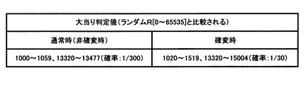
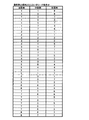
図11は、大当り判定テーブルを示す説明図である。大当り判定テーブルとは、ROM54に記憶されているデータの集まりであって、ランダムRと比較される大当り判定値が設定されているテーブルである。大当り判定テーブルには、通常状態(確変状態でない遊技状態)において用いられる通常時大当り判定テーブルと、確変状態において用いられる確変時大当り判定テーブルとがある。通常時大当り判定テーブルには、図11の左欄に記載されている各数値が設定され、確変時大当り判定テーブルには、図11の右欄に記載されている各数値が設定されている。図11に記載されている数値が大当り判定値である。
FIG. 11 is an explanatory diagram showing a jackpot determination table. The jackpot determination table is a collection of data stored in the
CPU56は、所定の時期に、乱数回路503のカウント値を抽出して抽出値を大当り判定用乱数(ランダムR)の値とするのであるが、大当り判定用乱数値が図11に示すいずれかの大当り判定値に一致すると、特別図柄に関して大当り(確変大当り、通常大当りもしくは突確大当り)にすることに決定する。なお、図11に示す「確率」は、大当りになる確率(割合)を示す。また、大当りにするか否か決定するということは、大当り遊技状態に移行させるか否か決定するということであるが、第1特別図柄表示器8aまたは第2特別図柄表示器8bにおける停止図柄を大当り図柄にするか否か決定するということでもある。
The
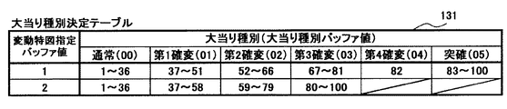
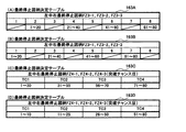
ROMが記憶する決定テーブルには、図12に示す大当り種別決定テーブル131が含まれている。大当り種別決定テーブル131は、可変表示結果を「大当り」とする旨の判定がなされたときに、大当り種別判定用の乱数値に基づき、演出図柄の可変表示態様を「通常」、「第1確変」〜「第4確変」、「突確」といった複数種類の大当り種別のいずれかに決定するために参照されるテーブルである。大当り種別決定テーブル131は、図23に示す遊技制御バッファ設定部155に設けられた変動特図指定バッファの値(変動特図指定バッファ値)が“1”であるか“2”であるかに応じて、大当り種別判定用の乱数値を、「通常」、「第1確変」〜「第4確変」、「突確」の大当り種別に割り当てる決定用データなどから構成されている。また、大当り種別決定テーブル131は、図23に示す遊技制御バッファ設定部155に設けられた大当り種別バッファの値(大当り種別バッファ値)を、大当り種別判定用の乱数値に基づいて決定された大当り種別に対応した「00」〜「05」のいずれかに設定するためのテーブルデータ(設定用データ)を含んでいてもよい。
The determination table stored in the ROM includes a jackpot type determination table 131 shown in FIG. When it is determined that the variable display result is “big hit”, the big hit type determination table 131 sets the variable symbol display mode of the effect symbol as “normal” and “first probability change” based on the random number value for determining the big hit type. This table is referred to in order to determine one of a plurality of types of jackpot types such as “fourth probability variation” and “surprise accuracy”. In the jackpot type determination table 131, whether the value of the variation special figure designation buffer (fluctuation special figure designation buffer value) provided in the game control
ここで、図12に示す大当り種別決定テーブル131の設定では、変動特図指定バッファ値が“1”であるか“2”であるかに応じて、「第4確変」、「突確」の大当り種別に対する大当り種別判定用の乱数値の割当てが異なっている。すなわち、変動特図指定バッファ値が“1”である場合には、大当り種別判定用の乱数値のうち「82」が「第4確変」の大当り種別に割り当てられ、「83」〜「100」の範囲の値が「突確」の大当り種別に割り当てられる一方で、変動特図指定バッファ値が“2”である場合には、「第4確変」、「突確」の大当り種別に対して大当り種別判定用の乱数値が割り当てられていない。このような設定により、第1特別図柄表示器8aによる第1特図を用いた特図ゲームを開始するための第1開始条件が成立したことに基づいて大当り種別を複数種類のいずれかに決定する場合と、第2特別図柄表示器8bによる第2特図を用いた特図ゲームを開始するための第2開始条件が成立したことに基づいて大当り種別を複数種類のいずれかに決定する場合とで、大当り種別を「第4確変」、「突確」に決定する割合を、異ならせることができる。
Here, in the setting of the big hit type determination table 131 shown in FIG. 12, depending on whether the fluctuation special figure designation buffer value is “1” or “2”, the big hit of “fourth probability variation” and “surprise probability” The assignment of the random value for determining the jackpot type to the type is different. That is, when the fluctuation special figure designation buffer value is “1”, “82” is assigned to the big hit type of “fourth probable change” among the random numbers for jackpot type determination, and “83” to “100”. If the value of the range is assigned to the “surprise” jackpot type and the variable special figure designation buffer value is “2”, the jackpot type for the “fourth odds” and “surprise” jackpot types A random number for judgment is not assigned. With such a setting, the jackpot type is determined as one of a plurality of types based on the fact that the first start condition for starting the special figure game using the first special figure by the first
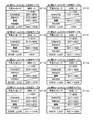
ROMが記憶する決定テーブルには、図13(A)〜(G)及び図14(A)〜(E)に示す大当り用変動パターン種別決定テーブル132A〜132Mが含まれている。大当り用変動パターン種別決定テーブル132A〜132Mは、可変表示結果を「大当り」とする旨の判定がなされたときに、大当り種別の判定結果に応じて、変動パターン種別を、変動パターン種別判定用の乱数値MR3に基づいて複数種類のいずれかに決定するために参照されるテーブルである。各大当り用変動パターン種別決定テーブル132A〜132Mは、例えば図14(F)に示すようなテーブル選択設定に従い、パチンコ遊技機1における遊技状態が通常状態、確変状態及び時短状態のいずれであるかや、大当り種別の判定結果、合計保留記憶数に応じて、使用テーブルとして選択される。各大当り用変動パターン種別決定テーブル132A〜132Mは、大当り種別の判定結果が「通常」、「第1確変」〜「第4確変」、「突確」のいずれであるかに応じて、変動パターン種別判定用の乱数値MR3を、ノーマルCA3−1、スーパーCA3−2〜スーパーCA3−8、スーパーCB3−1〜スーパーCB3−5、特殊CA4−1〜特殊CA4−3、特殊CA5−1、特殊CA5−2、特殊CB4−1、特殊CB4−2、特殊CB5−1、特殊CC4−1〜特殊CC4−3、特殊CC5−1、特殊CC5−2の変動パターン種別のいずれかに割り当てる決定用データなどから構成されている。
The determination table stored in the ROM includes jackpot variation pattern type determination tables 132A to 132M shown in FIGS. 13 (A) to (G) and FIGS. 14 (A) to (E). When the determination that the variable display result is “big hit” is made, the big hit variation pattern type determination tables 132A to 132M change the variation pattern type according to the determination result of the big hit type for the variation pattern type determination. It is a table referred to in order to determine any of a plurality of types based on the random value MR3. Each of the big hit variation pattern type determination tables 132A to 132M corresponds to, for example, whether the gaming state in the
ここで、一例として、パチンコ遊技機1における遊技状態が通常状態である場合に着目すれば、大当り種別が「通常」または「第3確変」である場合に用いられる図13(A)に示す大当り用変動パターン種別決定テーブル132Aと、大当り種別が「第1確変」ある場合に用いられる図13(B)に示す大当り用変動パターン種別決定テーブル132Bとでは、ノーマルCA3−1やスーパーCA3−2の変動パターン種別に対する変動パターン種別判定用の乱数値MR3の割当てが異なっている。また、大当り用変動パターン種別決定テーブル132AではスーパーCA3−3の変動パターン種別に対して変動パターン種別判定用の乱数値MR3が割り当てられている一方で、大当り用変動パターン種別決定テーブル132BではスーパーCA3−3の変動パターン種別に対して変動パターン種別判定用の乱数値MR3が割り当てられていない。他方、大当り用変動パターン種別決定テーブル132AではスーパーCA3−4の変動パターン種別に対して変動パターン種別判定用の乱数値MR3が割り当てられていない一方で、大当り用変動パターン種別決定テーブル132BではスーパーCA3−4の変動パターン種別に対して変動パターン種別判定用の乱数値MR3が割り当てられている。このように、パチンコ遊技機1における遊技状態が通常状態、確変状態及び時短状態のいずれかである場合に着目して、その遊技状態において大当り種別に応じて選択される大当り用変動パターン種別決定テーブル132A〜132Eや(通常状態のときに選択)、大当り用変動パターン種別決定テーブル132F〜132J(確変状態のときに選択)、大当り用変動パターン種別決定テーブル132A〜132D、132K、132M(時短状態のときに選択)を互いに比較すると、大当り種別に応じて各変動パターン種別に対する変動パターン種別判定用の乱数値MR3の割当てが異なっており、また、大当り種別に応じて異なる変動パターン種別に対して変動パターン種別判定用の乱数値MR3が割り当てられている。これにより、大当り種別を複数種類のいずれとするかの決定結果に応じて、異なる変動パターン種別に決定することが可能となり、同一の変動パターン種別に決定される割合を異ならせることができる。
Here, as an example, if attention is paid to the case where the gaming state in the
特に、大当り種別が「第4確変」である場合に用いられる大当り用変動パターン種別決定テーブル132D、132I、132Kでは、例えば特殊CA5−1、特殊CA5−2、特殊CB5−1、特殊CC5−1、特殊CC5−2といった、大当り種別が「第4確変」以外である場合には変動パターン種別判定用の乱数値MR3が割り当てられない変動パターン種別に対して、変動パターン種別判定用の乱数値MR3が割り当てられている。これにより、可変表示結果が「大当り」となり大当り種別が「第4確変」となることに応じて突確見せ掛け15ラウンド大当り状態に制御する場合には、15ラウンド大当り状態に制御する場合や2ラウンド大当り状態に制御する場合とは異なる変動パターン種別に決定することができる。 In particular, in the big hit variation pattern type determination tables 132D, 132I, and 132K used when the big hit type is “fourth probability variation”, for example, special CA5-1, special CA5-2, special CB5-1, and special CC5-1. When the jackpot type is other than “fourth probable variation”, such as special CC5-2, the random value MR3 for determining the variation pattern type is compared with the variation pattern type to which the random value MR3 for determining the variation pattern type is not assigned. Is assigned. As a result, when the variable display result is “big hit” and the big hit type is “fourth probability variation”, when controlling to the 15 round round big hit state, when controlling to the 15 round big hit state, The variation pattern type can be determined differently from the case of controlling to the state.
大当り種別が「第4確変」である場合に用いられる大当り用変動パターン種別決定テーブル132Dの設定では、合計保留記憶数が「0」〜「4」のいずれかである場合に対応して、変動パターン種別判定用の乱数値MR3の全てが、特殊CA5−1の変動パターン種別に割り当てられている一方で、合計保留記憶数が「5」〜「8」のいずれかである場合に対応して、変動パターン種別判定用の乱数値MR3の全てが、特殊CA5−2の変動パターン種別に割り当てられている。このため、パチンコ遊技機1の遊技状態が通常状態において、可変表示結果が「大当り」となり大当り種別が「第4確変」となるときには、合計保留記憶数が所定数(例えば「5」)未満であれば特殊CA5−1の変動パターン種別が決定される一方で、合計保留記憶数が所定数以上であれば、特殊CA5−2の変動パターン種別が決定されることとなる。
In the setting of the variation pattern type determination table 132D for big hits used when the big hit type is “fourth probability variation”, the variation corresponding to the case where the total number of reserved memories is “0” to “4” Corresponding to the case where all of the random numbers MR3 for pattern type determination are assigned to the variation pattern type of special CA5-1, while the total number of reserved storages is any one of “5” to “8”. The random number MR3 for determining the variation pattern type is all assigned to the variation pattern type of the special CA5-2. For this reason, when the gaming state of the
また、大当り用変動パターン種別決定テーブル132Iの設定では、合計保留記憶数が「0」〜「8」のいずれかの場合においても、特殊CB5−1の変動パターン種別に変動パターン種別判定用の乱数値MR3の全てが割り当てられている。このため、パチンコ遊技機1の遊技状態が確変状態において、可変表示結果が「大当り」となり大当り種別が「第4確変」となるときには、合計保留記憶数が「0」〜「8」のいずれであっても、特殊CB5−1の変動パターン種別が決定される。
Further, in the setting of the big hit variation pattern type determination table 132I, even when the total number of reserved memories is “0” to “8”, the variation pattern type of the special CB5-1 is changed to the variation pattern type determination variation. All of the numerical values MR3 are assigned. For this reason, when the gaming state of the
そして、大当り用変動パターン種別決定テーブル132Kの設定では、合計保留記憶数が「0」〜「4」のいずれかである場合に対応して、変動パターン種別判定用の乱数値MR3の全てが、特殊CC5−1の変動パターン種別に割り当てられている一方で、合計保留記憶数が「5」〜「8」のいずれかである場合に対応して、変動パターン種別判定用の乱数値MR3の全てが、特殊CC5−2の変動パターン種別に割り当てられている。このため、パチンコ遊技機1の遊技状態が時短状態において、可変表示結果が「大当り」となり大当り種別が「第4確変」となるときには、合計保留記憶数が所定数(例えば「5」)未満であれば、特殊CC5−1の変動パターン種別が決定される一方で、合計保留記憶数が所定数以上あれば、特殊CC5−2の変動パターン種別が決定されることとなる。
In the setting of the big hit variation pattern type determination table 132K, all of the random numbers MR3 for variation pattern type determination correspond to the case where the total number of reserved memories is “0” to “4”. While allotted to the variation pattern type of the special CC 5-1, the
さらに、大当り種別が「突確」である場合に用いられる大当り用変動パターン種別決定テーブル132Eの設定では、合計保留記憶数が「0」〜「4」のいずれかである場合に対応して、変動パターン種別判定用の乱数値MR3のうち、「1」〜「200」の範囲の値が特殊CA4−1の変動パターン種別に割り当てられている一方で、「201」〜「241」の範囲の値が特殊CA4−2の変動パターン種別に割り当てられている。これに対して、合計保留記憶数が「5」〜「8」のいずれかである場合に対応して、変動パターン種別判定用の乱数値MR3のうち、「1」〜「180」の範囲の値が特殊CA4−1の変動パターン種別に割り当てられている一方で、「181」〜「241」の範囲の値が特殊CA4−3の変動パターン種別に割り当てられている。このため、パチンコ遊技機1の遊技状態が時短状態において、可変表示結果が「大当り」となり大当り種別が「突確」となるときには、合計保留記憶数が所定数(例えば「5」)未満であれば、特殊CA4−1、特殊CA4−2のいずれかの変動パターン種別が決定される一方で、合計保留記憶数が所定数以上あれば、特殊CA4−1、特殊CA4−3のいずれかの変動パターン種別が決定されることとなる。また、このような設定により、合計保留記憶数が所定数(例えば「5」)以上であるときには、所定数未満であるときに比べて、特殊CA4−1の変動パターン種別に決定される割合が低くなる。
Furthermore, in the setting of the variation pattern type determination table 132E for big hits used when the big hit type is “surprise”, the change corresponding to the case where the total number of reserved memories is “0” to “4” Among the random values MR3 for pattern type determination, values in the range of “1” to “200” are assigned to the variation pattern types of the special CA4-1, while values in the range of “201” to “241”. Is assigned to the variation pattern type of special CA4-2. On the other hand, corresponding to the case where the total reserved storage number is any one of “5” to “8”, the random value MR3 for determining the variation pattern type is in the range of “1” to “180”. While the value is assigned to the variation pattern type of special CA4-1, the value in the range of “181” to “241” is assigned to the variation pattern type of special CA4-3. For this reason, when the game state of the
また、大当り種別が「突確」である場合に用いられる大当り用変動パターン種別決定テーブル132Jの設定では、合計保留記憶数が「0」〜「8」のいずれかの場合においても、変動パターン種別判定用の乱数値MR3のうち、「1」〜「150」の範囲の値が特殊CB4−1の変動パターン種別に割り当てられている一方で、「151」〜「241」の範囲の値が特殊CB4−2の変動パターン種別に割り当てられている。このため、パチンコ遊技機1の遊技状態が確変状態において、可変表示結果が「大当り」となり大当り種別が「突確」となるときには、合計保留記憶数が「0」〜「8」のいずれであっても、特殊CB4−1、特殊CB4−2のいずれかの変動パターン種別が決定される。
Further, in the setting of the big hit variation pattern type determination table 132J used when the big hit type is “surprise”, even when the total number of stored storage is “0” to “8”, the fluctuation pattern type determination Among the random number values MR3 for use, values in the range of “1” to “150” are assigned to the variation pattern types of the special CB4-1, while values in the range of “151” to “241” are the special CB4. -2 variation pattern type. Therefore, when the gaming state of the
そして、大当り用変動パターン種別決定テーブル132Mの設定では、合計保留記憶数が「0」〜「4」のいずれかである場合に対応して、変動パターン種別判定用の乱数値MR3のうち、「1」〜「175」の範囲の値が特殊CC4−1の変動パターン種別に割り当てられている一方で、「176」〜「241」の範囲の値が特殊CC4−2の変動パターン種別に割り当てられている。これに対して、合計保留記憶数が「5」〜「8」のいずれかである場合に対応して、変動パターン種別判定用の乱数値MR3のうち、「1」〜「150」の範囲の値が特殊CC4−1の変動パターン種別に割り当てられている一方で、「151」〜「241」の範囲の値が特殊CC4−3の変動パターン種別に割り当てられている。このため、パチンコ遊技機1の遊技状態が時短状態において、可変表示結果が「大当り」となり大当り種別が「突確」となるときには、合計保留記憶数が所定数(例えば「5」)未満であれば、特殊CC4−1、特殊CC4−2のいずれかの変動パターン種別が決定される一方で、合計保留記憶数が所定数以上あれば、特殊CC4−1、特殊CC4−3のいずれかの変動パターン種別が決定されることとなる。また、このような設定により、合計保留記憶数が所定数(例えば「5」)以上であるときには、所定数未満であるときに比べて、特殊CC4−1の変動パターン種別に決定される割合が低くなる。
Then, in the setting of the big hit variation pattern type determination table 132M, in response to the case where the total number of reserved memories is “0” to “4”, among the random value MR3 for variation pattern type determination, “ The value in the range of “1” to “175” is assigned to the variation pattern type of the special CC4-1, while the value in the range of “176” to “241” is assigned to the variation pattern type of the special CC4-2. ing. On the other hand, corresponding to the case where the total reserved storage number is any one of “5” to “8”, the random value MR3 for determining the variation pattern type is in the range of “1” to “150”. While the value is assigned to the variation pattern type of the special CC 4-1, the value in the range of “151” to “241” is assigned to the variation pattern type of the special CC 4-3. For this reason, when the game state of the
他の一例として、可変表示結果が「大当り」であり大当り種別が「突確」である場合に用いられる大当り用変動パターン種別決定テーブル132D、132J、132Mでは、例えば特殊CA4−1、特殊CA4−2、特殊CA4−3、特殊CB4−1、特殊CB4−2、特殊CC4−1、特殊CC4−2、特殊CC4−3といった、可変表示結果が「大当り」であり大当り種別が「突確」以外である場合には変動パターン種別判定用の乱数値MR3が割り当てられない変動パターン種別に対して、変動パターン種別判定用の乱数値MR3が割り当てられている。これにより、可変表示結果が「大当り」となり大当り種別が「突確」となることに応じて2ラウンド大当り状態に制御する場合には、15ラウンド大当り状態や突確見せ掛け15ラウンド大当り状態に制御する場合とは異なる変動パターン種別に決定することができる。
As another example, in the big hit variation pattern type determination tables 132D, 132J, and 132M used when the variable display result is “big hit” and the big hit type is “surprise”, for example, special CA4-1, special CA4-2 , Special CA4-3, special CB4-1, special CB4-2, special CC4-1, special CC4-2, special CC4-3, the variable display result is "big hit" and the big hit type is other than "surprise" In this case, the random value MR3 for determining the variation pattern type is assigned to the variation pattern type to which the random value MR3 for determining the variation pattern type is not assigned. As a result, when the variable display result is “big hit” and the type of big hit is “surprise”, the control is made to the round two big hit state, the case of controlling to the
また、他の一例として、大当り種別が「通常」に決定された場合に着目すれば、パチンコ遊技機1 における遊技状態が通常状態や時短状態である場合に用いられる図13(A)に示す大当り用変動パターン種別決定テーブル132Aと、遊技状態が確変状態である場合に用いられる図13(F)に示す大当り用変動パターン種別決定テーブル132Fとでは、ノーマルCA3−1やスーパーCA3−2の変動パターン種別に対する変動パターン種別判定用の乱数値MR3 の割当てが異なっている。また、大当り用変動パターン種別決定テーブル132AではスーパーCA3−3の変動パターン種別に対して変動パターン種別判定用の乱数値MR3が割り当てられている一方で、大当り用変動パターン種別決定テーブル132F ではスーパーCA3−3 の変動パターン種別に対して変動パターン種別判定用の乱数値MR3 が割り当てられていない。このように、大当り種別が「通常」、「第1確変」〜「第4確変」、「突確」のいずれかに決定された場合に着目して、パチンコ遊技機1における遊技状態に応じて選択される大当り用変動パターン種別決定テーブル13 2A、132F(「通常」または「第3 確変」のときに選択)、大当り用変動パターン種別決定テーブル132B、132G(「第1 確変」のときに選択)、大当り用変動パターン種別決定テーブル132C、132H(「第2 確変」のときに選択)、大当り用変動パターン種別決定テーブル132D、132I(「第4確変」のときに選択)、大当り用変動パターン種別決定テーブル132E、132J、132M(「突確」のときに選択) を互いに比較すると、パチンコ遊技機1における遊技状態が通常状態や時短状態であるか確変状態であるかなどに応じて各変動パターン種別に対する変動パターン種別判定用の乱数値MR3の割当てが異なっており、また、遊技状態に応じて異なる変動パターン種別に対して変動パターン種別判定用の乱数値MR3 が割り当てられることがある。これにより、パチンコ遊技機1 における遊技状態が通常状態や時短状態であるか確変状態であるかなどに応じて、異なる変動パターン種別に決定することが可能となり、同一の変動パターン種別に決定される割合を異ならせることができる。
As another example, focusing on the case where the jackpot type is determined to be “normal”, the jackpot shown in FIG. 13 (A) used when the gaming state in the
ROMが記憶する決定テーブルには、図15(A)〜(C)に示すリーチ決定テーブル134A〜134Cが含まれている。リーチ決定テーブル134A〜134Cは、可変表示結果を「ハズレ」とする旨の判定がなされたときに、演出図柄の可変表示状態をリーチ状態とするか否かを、リーチ判定用の乱数値に基づいて判定するために参照されるテーブルである。各リーチ決定テーブル134A〜134Cは、例えば図15(D)に示すようなテーブル選択設定に従い、パチンコ遊技機1における遊技状態が通常状態、確変状態及び時短状態のいずれであるかに応じて、使用テーブルとして選択される。各リーチ決定テーブル134A〜134Cは、リーチ判定用の乱数値を、非リーチHA1−1〜非リーチHA1−5、非リーチHB1−1、非リーチHB1−2、非リーチHC1−1、非リーチHC1−2といったリーチ状態としない旨の判定結果や、リーチHA2−1〜リーチHA2−3、リーチHB2−1、リーチHC2−1といったリーチ状態とする旨の判定結果のいずれかに割り当てる決定用データなどから構成されている。
The determination table stored in the ROM includes reach determination tables 134A to 134C shown in FIGS. The reach determination tables 134 </ b> A to 134 </ b> C indicate whether or not the variable display state of the effect symbol is set to the reach state when it is determined that the variable display result is “losing” based on the random number value for reach determination. This table is referred to for determination. Each reach determination table 134A to 134C is used depending on whether the gaming state in the
ここで、例えば図15(A)に示すリーチ決定テーブル134Aの設定では、合計保留記憶数が「0」である場合に対応して、リーチ判定用の乱数値のうち「1」〜「204」の範囲の値を非リーチHA1−1の判定結果に割り当てる一方で「205」〜「239」の範囲の値をリーチHA2−1の判定結果に割り当てる。また、合計保留記憶数が「1」である場合に対応して、リーチ判定用の乱数値MR2−2のうち非リーチHA1−1に割り当てる乱数値の個数よりも多い「1」〜「217」の範囲の値を、非リーチHA1−2の判定結果に割り当てる。さらに、合計保留記憶数が「2」である場合に対応して、リーチ判定用の乱数値MR2−2のうち非リーチHA1−1や非リーチHA1−2に割り当てる乱数値の個数よりも多い「1」〜「220」の範囲の値を、非リーチHA1−3の判定結果に割り当てる。合計保留記憶数が「3」または「4」である場合や「5」〜「8」のいずれかである場合のそれぞれに対応して、リーチ判定用の乱数値MR2−2のうち非ーチHA1−1〜非リーチHA1−3の判定結果のそれぞれに割り当てる乱数値の個数よりも多い「1」〜「230」の範囲の値を、非リーチHA1−4や非リーチHA1−5の判定結果に割り当てる。このような設定により、合計保留記憶数が所定数(例えば「3」)以上であるときには、所定数未満であるときに比べて、演出図柄の可変表示状態をリーチ状態とする旨の判定がなされる割合が低くなる。そして、「非リーチ」に対応した変動パターンにおける平均的な特図変動時間が「リーチ」に対応した変動パターンにおける平均的な特図変動時間に比べて短くなるように設定されていれば、合計保留記憶数が所定数以上であるときには、所定数未満であるときに比べて、平均的な特図変動時間を短縮することができる。 Here, for example, in the setting of the reach determination table 134A shown in FIG. 15 (A), “1” to “204” among the random numbers for reach determination, corresponding to the case where the total reserved storage number is “0”. A value in the range of “205” to “239” is assigned to a determination result of reach HA 2-1 while a value in the range of “2” is assigned to the determination result of non-reach HA 1-1. Corresponding to the case where the total reserved storage number is “1”, “1” to “217”, which are larger than the number of random number values assigned to the non-reach HA 1-1 among the random numbers MR2-2 for reach determination. Is assigned to the determination result of non-reach HA1-2. Furthermore, corresponding to the case where the total number of reserved storage is “2”, the number of random numbers MR2-2 for reach determination is larger than the number of random values assigned to non-reach HA1-1 and non-reach HA1-2. A value in the range of “1” to “220” is assigned to the determination result of non-reach HA1-3. Corresponding to each of the cases where the total number of reserved storages is “3” or “4” or any of “5” to “8”, non-reach among the random numbers MR2-2 for reach determination. A value in the range of “1” to “230”, which is larger than the number of random numbers assigned to each of the determination results of HA1-1 to non-reach HA1-3, is determined as a determination result of non-reach HA1-4 and non-reach HA1-5. Assign to. With this setting, when the total number of reserved memories is equal to or greater than a predetermined number (for example, “3”), it is determined that the variable display state of the effect symbol is set to the reach state as compared to when the total number is less than the predetermined number. The ratio is lower. If the average special figure fluctuation time in the fluctuation pattern corresponding to “non-reach” is set to be shorter than the average special figure fluctuation time in the fluctuation pattern corresponding to “reach”, the total When the number of reserved memories is equal to or greater than the predetermined number, the average special figure fluctuation time can be shortened compared to when the number is less than the predetermined number.
ROMが記憶する決定テーブルには、図16(A)〜(C)に示すリーチ用変動パターン種別決定テーブル135A〜135Cが含まれている。リーチ用変動パターン種別決定テーブル135A〜135Cは、演出図柄の可変表示状態をリーチ状態とする旨の判定がなされたときに、変動パターン種別を、変動パターン種別判定用の乱数値MR3に基づいて複数種類のいずれかに決定するために参照されるテーブルである。各リーチ用変動パターン種別決定テーブル135A〜135Cは、リーチHA2−1〜リーチHA2−3、リーチHB2−1、リーチHC2−1といったリーチ状態とする旨の判定結果に応じて、使用テーブルとして選択される。すなわち、リーチHA2−1〜リーチHA2−3の判定結果に応じてリーチ用変動パターン種別決定テーブル135Aが使用テーブルとして選択され、リーチHB2−1の判定結果に応じてリーチ用変動パターン種別決定テーブル135Bが使用テーブルとして選択され、リーチHC2−1の判定結果に応じてリーチ用変動パターン種別決定テーブル135Cが使用テーブルとして選択される。各リーチ用変動パターン種別決定テーブル135A〜135Cは、リーチ状態とする旨の判定結果がリーチHA2−1〜リーチHA2−3、リーチHB2−1、リーチHC2−1のいずれであるかに応じて、変動パターン種別判定用の乱数値MR3を、ノーマルCA2−1、スーパーCA2−2、スーパーCA2−3、スーパーCB2−1、スーパーCB2−2の変動パターン種別のいずれかに割り当てる決定用データなどから構成されている。 The determination table stored in the ROM includes reach variation pattern type determination tables 135A to 135C shown in FIGS. The reach variation pattern type determination tables 135A to 135C include a plurality of variation pattern types based on the random value MR3 for variation pattern type determination when it is determined that the variable display state of the effect symbol is the reach state. A table that is referenced to determine one of the types. Each of the reach variation pattern type determination tables 135A to 135C is selected as a use table in accordance with a determination result indicating reach state such as reach HA2-1 to reach HA2-3, reach HB2-1, reach HC2-1. The That is, the reach variation pattern type determination table 135A is selected as a usage table according to the determination results of the reach HA2-1 to the reach HA2-3, and the reach variation pattern type determination table 135B according to the determination result of the reach HB2-1. Is selected as the usage table, and the reach variation pattern type determination table 135C is selected as the usage table in accordance with the determination result of the reach HC2-1. Each of the reach variation pattern type determination tables 135A to 135C has a reach determination result indicating whether the reach state is reach HA2-1 to reach HA2-3, reach HB2-1, or reach HC2-1. The random value MR3 for determining the variation pattern type is composed of data for determination assigned to any one of the variation pattern types of normal CA2-1, super CA2-2, super CA2-3, super CB2-1, and super CB2-2. Has been.
ここで、例えば図16(A)に示すリーチ用変動パターン種別決定テーブル135Aの設定では、リーチHA2−1の判定結果に対応して、変動パターン種別判定用の乱数値MR3のうち「1」〜「128」の範囲の値をノーマルCA2−1の変動パターン種別に割り当てる一方で、それ以外の乱数値をスーパーCA2−2やスーパーCA2−3の変動パターン種別に割り当てる。また、リーチHA2−2の判定結果に対応して、変動パターン種別判定用の乱数値MR3のうち「1」〜「170」の範囲の値をノーマルCA2−1の変動パターン種別に割り当てる。さらに、リーチHA2−3の判定結果に対応して、変動パターン種別判定用の乱数値MR3のうち「1」〜「182」の範囲の値をノーマルCA2−1の変動パターン種別に割り当てる。リーチHA2−1の判定結果は、図15(A)に示すリーチ決定テーブル134Aの設定により、合計保留記憶数が「0」である場合に対応して、リーチ判定用の乱数値が割り当てられている。リーチHA2−2の判定結果は、合計保留記憶数が「1」である場合や「2」である場合に対応して、リーチ判定用の乱数値MR2−2が割り当てられている。リーチHA2−3の判定結果は、合計保留記憶数が「3」、「4」のいずれかである場合や「5」〜「8」のいずれかである場合に対応して、リーチ判定用の乱数値MR2−2が割り当てられている。これらの設定により、合計保留記憶数が所定数(例えば「1」)以上であるときには、所定数未満であるときに比べて、「ノーマル」のリーチ演出が実行されるノーマルCA2−1の変動パターン種別に決定される割合が高くなる。そして、「ノーマル」のリーチ演出を実行する変動パターンにおける平均的な特図変動時間が「ノーマル」以外のリーチ演出を実行する変動パターンにおける平均的な特図変動時間に比べて短くなるように設定されていれば、合計保留記憶数が所定数以上であるときには、所定数未満であるときに比べて、平均的な特図変動時間を短縮することができる。 Here, for example, in the setting of the reach variation pattern type determination table 135A shown in FIG. 16A, “1” to “1” of the random value MR3 for variation pattern type determination corresponding to the determination result of the reach HA2-1. A value in the range of “128” is assigned to the variation pattern type of normal CA2-1, while other random values are assigned to the variation pattern types of super CA2-2 and super CA2-3. Corresponding to the determination result of reach HA2-2, a value in the range of “1” to “170” is assigned to the variation pattern type of normal CA2-1 in the random value MR3 for variation pattern type determination. Further, according to the determination result of reach HA2-3, a value in the range of “1” to “182” is assigned to the variation pattern type of normal CA2-1 among the random value MR3 for variation pattern type determination. The determination result of the reach HA 2-1 is that a reach determination random number value is assigned in accordance with the setting of the reach determination table 134 A shown in FIG. Yes. As the determination result of the reach HA 2-2, the random number value MR2-2 for the reach determination is assigned corresponding to the case where the total reserved storage number is “1” or “2”. The determination result of reach HA2-3 indicates that the total pending storage number is either “3” or “4” or any of “5” to “8”. A random value MR2-2 is assigned. With these settings, when the total number of reserved memories is a predetermined number (for example, “1”) or more, the fluctuation pattern of the normal CA 2-1 in which the “normal” reach effect is executed is compared to when the total number is less than the predetermined number. The rate determined for the type increases. And the average special figure fluctuation time in the fluctuation pattern that executes the “normal” reach production is set to be shorter than the average special figure fluctuation time in the fluctuation pattern that executes the reach production other than “normal”. If so, when the total number of reserved memories is greater than or equal to the predetermined number, the average special figure variation time can be shortened as compared to when the total number is less than the predetermined number.
ROMが記憶する決定テーブルには、図17(A)〜(C)に示す非リーチ用変動パターン種別決定テーブル136A〜136Cが含まれている。非リーチ用変動パターン種別決定テーブル136A〜136Cは、演出図柄の可変表示状態をリーチ状態としない旨の判定がなされたときに、変動パターン種別を、変動パターン種別判定用の乱数値MR3に基づいて複数種類のいずれかに決定するために参照されるテーブルである。各非リーチ用変動パターン種別決定テーブル136A〜136Cは、非リーチHA1−1〜非リーチHA1−5、非リーチHB1−1、非リーチHB1−2、非リーチHC1−1、非リーチHC1−2といったリーチ状態としない旨の判定結果に応じて、使用テーブルとして選択される。すなわち、非リーチHA1−1〜非リーチHA1−5の判定結果に応じて非リーチ用変動パターン種別決定テーブル136Aが使用テーブルとして選択され、非リーチHB1−1、非リーチHB1−2の判定結果に応じて非リーチ用変動パターン種別決定テーブル136Bが使用テーブルとして選択され、非リーチHC1−1、非リーチHC1−2の判定結果に応じて非リーチ用変動パターン種別決定テーブル136Cが使用テーブルとして選択される。各非リーチ用変動パターン種別決定テーブル136A〜136Cは、リーチ状態としない旨の判定結果が非リーチHA1−1〜非リーチHA1−5、非リーチHB1−1、非リーチHB1−2、非リーチHC1−1、非リーチHC1−2のいずれであるかに応じて、変動パターン種別判定用の乱数値MR3を、非リーチCA1−1〜非リーチCA1−4、非リーチCB1−1〜非リーチCB1−3、非リーチCC1−1〜非リーチCC1−3の変動パターン種別のいずれかに割り当てる決定用データなどから構成されている。 The determination table stored in the ROM includes non-reach variation pattern type determination tables 136A to 136C shown in FIGS. The non-reach variation pattern type determination tables 136A to 136C indicate that when it is determined that the variable display state of the effect symbol is not the reach state, the variation pattern type is determined based on the random value MR3 for variation pattern type determination. It is a table that is referred to in order to determine one of a plurality of types. The non-reach variation pattern type determination tables 136A to 136C include non-reach HA1-1 to non-reach HA1-5, non-reach HB1-1, non-reach HB1-2, non-reach HC1-1, and non-reach HC1-2. It is selected as a use table according to the determination result indicating that the reach state is not set. That is, the non-reach variation pattern type determination table 136A is selected as a use table in accordance with the determination results of the non-reach HA1-1 to non-reach HA 1-5, and the determination results of the non-reach HB1-1 and non-reach HB1-2. Accordingly, the non-reach variation pattern type determination table 136B is selected as the use table, and the non-reach variation pattern type determination table 136C is selected as the use table according to the determination results of the non-reach HC1-1 and non-reach HC1-2. The In each of the non-reach variation pattern type determination tables 136A to 136C, the determination result indicating that the reach state is not set is non-reach HA1-1 to non-reach HA1-5, non-reach HB1-1, non-reach HB1-2, non-reach HC1. -1 and non-reach HC1-2, the random value MR3 for determining the variation pattern type is determined as non-reach CA1-1 to non-reach CA1-4, non-reach CB1-1 to non-reach CB1-. 3. It is comprised from the data for determination etc. which are allocated to one of the variation pattern types of non-reach CC1-1 to non-reach CC1-3.
ROMが記憶する決定テーブルには、図18、図19(A)及び(B)、図20に示す当り変動パターン決定テーブル137A〜137Dが含まれている。当り変動パターン決定テーブル137A〜137Dは、可変表示結果を「大当り」とする旨の判定がなされたときに、大当り種別や変動パターン種別の決定結果などに応じて、変動パターンを、変動パターン判定用の乱数値MR4に基づいて複数種類のいずれかに決定するために参照されるテーブルである。各当り変動パターン決定テーブル137A〜137Dは、変動パターン種別の決定結果に応じて、使用テーブルとして選択される。すなわち、変動パターン種別をノーマルCA3−1、スーパーCA3−2〜スーパーCA3−8のいずれかとする旨の決定結果に応じて当り変動パターン決定テーブル137Aが使用テーブルとして選択され、変動パターン種別をスーパーCB3−1〜スーパーCB3−5のいずれかとする旨の決定結果に応じて当り変動パターン決定テーブル137Bが使用テーブルとして選択され、変動パターン種別を特殊CA4−1〜特殊CA4−3、特殊CB4−1、特殊CB4−2、特殊CC4−1〜特殊CC4−3のいずれかとする旨の決定結果に応じて当り変動パターン決定テーブル137Cが使用テーブルとして選択され、変動パターン種別を特殊CA5−1、特殊CA5−2、特殊CB5−1、特殊CC5−1、特殊CC5−2のいずれかとする旨の決定結果に応じて当り変動パターン決定テーブル137Dが使用テーブルとして選択される。各当り変動パターン決定テーブル137A〜137Dは、変動パターン種別に応じて、変動パターン判定用の乱数値MR4を、演出図柄の可変表示結果が「大当り」である場合に対応した複数種類の変動パターンのいずれかに割り当てる決定用データなどから構成されている。 The determination tables stored in the ROM include hit variation pattern determination tables 137A to 137D shown in FIGS. 18, 19A and 19B, and FIG. When the hit variation pattern determination tables 137A to 137D determine that the variable display result is “big hit”, the variation pattern is determined for the variation pattern according to the determination result of the big hit type or the variation pattern type. This table is referred to in order to determine one of a plurality of types based on the random value MR4. Each of the variation pattern determination tables 137A to 137D is selected as a use table according to the determination result of the variation pattern type. That is, the hit variation pattern determination table 137A is selected as the use table in accordance with the determination result that the variation pattern type is either normal CA3-1 or super CA3-2 to super CA3-8, and the variation pattern type is super CB3. -1 to Super CB3-5, the hit variation pattern determination table 137B is selected as the use table according to the determination result, and the variation pattern types are special CA4-1 to special CA4-3, special CB4-1, The hit variation pattern determination table 137C is selected as the use table in accordance with the determination result indicating that any one of the special CB4-2 and the special CC4-1 to the special CC4-3 is used, and the variation pattern type is the special CA5-1 or the special CA5-. 2, Special CB5-1, Special CC5-1, Special CC5-2 Per variation pattern determination table 137D according to the determination result to the effect that is selected as the usage table. Each of the winning variation pattern determination tables 137A to 137D includes a random number MR4 for determining the variation pattern according to the variation pattern type, and a plurality of types of variation patterns corresponding to the case where the variable display result of the effect symbol is “big hit”. It consists of decision data to be assigned to either.
ここで、図18に示す当り変動パターン決定テーブル137Aの設定では、ノーマルCA3−1の変動パターン種別となる場合に対応して、ノーマルPA2−5〜ノーマルPA2−8といった「ノーマル」のリーチ演出を実行する変動パターンに、変動パターン判定用の乱数値MR4が割り当てられている。また、スーパーCA3−2の変動パターン種別となる場合に対応して、スーパーPA4−1〜スーパーPA4−5といったリーチ演出α1を実行する変動パターンや、スーパーPA4−6〜スーパーPA4−10といったリーチ演出α2を実行する変動パターンに、変動パターン判定用の乱数値MRが割り当てられている。スーパーCA3−3やスーパーCA3−4の変動パターン種別となる場合に対応して、スーパーPB4−1〜スーパーPB4−5、スーパーPC4−1、スーパーPD1−1、スーパーPD1−2といったリーチ演出β1を実行する変動パターンに、変動パターン判定用の乱数値MR4が割り当てられている。また、スーパーCA3−5の変動パターン種別となる場合に対応して、スーパーPA5−1〜スーパーPA5−5といったリーチ演出α3を実行する変動パターンに、変動パターン判定用の乱数値MR4が割り当てられている。スーパーCA3−6の変動パターン種別となる場合に対応して、スーパーPB5−1〜スーパーPB5−5、スーパーPE1−1、スーパーPE1−2といった確変大当り確定の演出を実行する変動パターンに、変動パターン判定用の乱数値MR4が割り当てられている。また、スーパーCA3−7の変動パターン種別となる場合に対応して、スーパーPC4−1、スーパーPC4−2といった「発展チャンス目」の特定演出を実行する変動パターンに、変動パターン判定用の乱数値MR4が割り当てられている。スーパーCA3−8の変動パターン種別となる場合に対応して、PF1−1といったリーチ演出β3を実行する変動パターンや、PF1−2、PF1−3といったルーレットチャンスの演出を実行する変動パターンに、変動パターン判定用の乱数値MR4が割り当てられている。 Here, in the setting of the hit variation pattern determination table 137A shown in FIG. 18, "normal" reach effects such as normal PA2-5 to normal PA2-8 are provided corresponding to the case where the variation pattern type is normal CA3-1. A random value MR4 for determining a variation pattern is assigned to the variation pattern to be executed. Corresponding to the variation pattern type of super CA 3-2, the variation pattern for executing reach effect α1 such as super PA4-1 to super PA4-5 and the reach effect such as super PA4-6 to super PA4-10. A random value MR for determining a variation pattern is assigned to the variation pattern for executing α2. In response to the variation pattern types of Super CA3-3 and Super CA3-4, reach effects β1 such as Super PB4-1 to Super PB4-5, Super PC4-1, Super PD1-1, and Super PD1-2 are provided. A random value MR4 for determining a variation pattern is assigned to the variation pattern to be executed. Corresponding to the case of the variation pattern type of super CA 3-5, random value MR4 for variation pattern determination is assigned to the variation pattern for executing reach effect α3 such as super PA5-1 to super PA5-5. Yes. Corresponding to the case of the variation pattern type of Super CA 3-6, the variation pattern is changed to the variation pattern that executes the effect of determining the probability variation big hit such as Super PB5-1 to Super PB5-5, Super PE1-1, Super PE1-2. A random number value MR4 for determination is assigned. Corresponding to the case of the variation pattern type of Super CA 3-7, a random value for variation pattern determination is added to the variation pattern that executes the “development chance” specific effects such as Super PC 4-1 and Super PC 4-2. MR4 is assigned. Corresponding to the variation pattern type of Super CA 3-8, the variation pattern changes to a variation pattern that executes a reach effect β3 such as PF1-1 or a variation pattern that executes a roulette chance effect such as PF1-2 or PF1-3. A random number MR4 for pattern determination is assigned.
また、図19(A)に示す当り変動パターン決定テーブル137Bの設定では、スーパーCB3−1の変動パターン種別となる場合に対応して、スーパーPB4−1〜スーパーPB4−5といったリーチ演出β1を実行する変動パターンに、変動パターン判定用の乱数値MR4が割り当てられている。また、スーパーCB3−2の変動パターン種別となる場合に対応して、スーパーPD1−1、スーパーPD1−2といったリーチ演出β1とルーレットの演出とを実行する変動パターンに、変動パターン判定用の乱数値MR4が割り当てられている。スーパーCB3−3の変動パターン種別となる場合に対応して、スーパーPB5−1〜スーパーPB5−5といったリーチ演出β2を実行する変動パターンに、変動パターン判定用の乱数値MR4が割り当てられている。また、スーパーCB3−4の変動パターン種別となる場合に対応して、スーパーPC4−1、スーパーPC4−2といった変動パターンに、変動パターン判定用の乱数値MR4が割り当てられている。スーパーCB3−5の変動パターン種別となる場合に対応して、スーパーPE1−1、スーパーPE1−2といったリーチ演出β2とルーレットの演出とを実行する変動パターンに、変動パターン判定用の乱数値MR4が割り当てられている。
Further, in the setting of the hit fluctuation pattern determination table 137B shown in FIG. 19A, the reach effect β1 such as the super PB4-1 to the super PB4-5 is executed corresponding to the case where the change pattern type is the super CB3-1. The random pattern MR4 for determining the variation pattern is assigned to the variation pattern. Corresponding to the case of the variation pattern type of the super CB 3-2, the variation pattern determination random number value for executing the
このような設定により、例えば図13及び図14に示す大当り用変動パターン種別決定テーブル132A〜132Mを参照して、ノーマルCA3−1の変動パターン種別とするか、それ以外の変動パターン種別とするかを決定することで、「ノーマル」のリーチ演出を実行するか否かを決定することができる。そして、ノーマルCA3−1の変動パターン種別が決定された場合には、図18に示す当り変動パターン決定テーブル137Aを参照して、ノーマルPA2−5〜ノーマルPA2−8の変動パターンのうちのいずれかに決定することで、「滑り」の特定演出を実行するか否かを決定することができる。 With such a setting, for example, referring to the big hit variation pattern type determination tables 132A to 132M shown in FIGS. 13 and 14, whether the variation pattern type is normal CA3-1 or other variation pattern types. It is possible to determine whether or not to execute the “normal” reach effect. When the variation pattern type of normal CA3-1 is determined, one of the variation patterns of normal PA2-5 to normal PA2-8 is referred to with reference to the hit variation pattern determination table 137A shown in FIG. It is possible to determine whether or not to execute a specific effect of “slip”.
また、ノーマルCA3−1以外の変動パターン種別として、例えばスーパーCA3−2の変動パターン種別が決定された場合には、図18に示す当り変動パターン決定テーブル137Aを参照して、スーパーPA4−1〜スーパーPA4−10の変動パターンのうちのいずれかに決定することで、特定演出を実行するか否かと、「滑り」、「擬似連」、「イントロ」のいずれの特定演出を実行するかと、例えば「擬似連」の特定演出における全再変動表示動作の実行回数などといった特定演出の種類とを決定することができるとともに、1段階目の演出表示で大当り組合せとなる演出図柄が停止表示(仮停止表示も含む)される演出図柄が出現するリーチ演出α1を実行するか、2段階目の演出表示で大当り組合せとなる演出図柄が停止表示(仮停止表示も含む)される演出図柄が出現するリーチ演出α2を実行するかを決定することができる。 In addition, as a variation pattern type other than the normal CA 3-1, for example, when the variation pattern type of the super CA 3-2 is determined, referring to the hit variation pattern determination table 137 A shown in FIG. By determining one of the fluctuation patterns of Super PA 4-10, whether or not to execute a specific effect, whether to execute a specific effect of “slip”, “pseudo-run”, or “intro”, for example, It is possible to determine the type of the specific effect such as the number of executions of the all-revariable display operation in the specific effect of the “pseudo ream”, and to stop the display of the effect symbol that is a big hit combination in the first stage effect display (Including the display) The reach effect α1 in which the effect symbol to be displayed appears is executed, or the effect symbol that becomes a jackpot combination in the second effect display is stopped and displayed Can performance symbol to temporary stop including display) by the determines whether to perform the reach demonstration α2 appearing.
ただし、大当り種別が「第2確変」である場合には、リーチ演出の種類に関わりなく、確変大当り確定の演出を一定の割合で出現させるために、例えば「発展チャンス目」の特定演出を実行する変動パターン種別(例えばスーパーCA3−7やスーパーCB3−4の変動パターン種別など)が設けられている。 However, when the jackpot type is “second probability change”, for example, a specific effect of “Development Chance Eye” is executed in order to cause a certain probability change jackpot appearance to appear at a certain rate regardless of the type of reach effect. Variation pattern types (for example, variation pattern types of super CA 3-7 and super CB 3-4) are provided.
図19(B)に示す当り変動パターン決定テーブル137Cの設定では、特殊CA4−1の変動パターン種別となる場合に対応して、特殊PG1−1、特殊PG1−2、特殊PG1−6、特殊PG2−1、特殊PG2−2といった変動パターンに、変動パターン判定用の乱数値MR4が割り当てられている。また、特殊CA4−2の変動パターン種別となる場合に対応して、特殊PG1−3といった全再変動表示動作が2回行われる「擬似連」の特定演出を実行する変動パターンや、特殊PG1−4といった全再変動表示動作が3回行われる「擬似連」の特定演出を実行する変動パターン、特殊PG3−1といった突確チャンス目TC1〜TC4のいずれかとなる演出図柄を停止表示する変動パターンなどの、可変表示結果が「大当り」であり大当り種別が「突確」である場合にのみ使用される変動パターンに、変動パターン判定用の乱数値MR4が割り当てられている。これに対して、特殊CA4−3の変動パターン種別となる場合に対応して、特殊PG1−5といった全再変動表示動作が1回行われる「擬似連」の特定演出を実行する変動パターンや、特殊PG3−1といった突確チャンス目TC1〜TC4のいずれかとなる演出図柄を停止表示する変動パターンなどの、可変表示結果が「大当り」であり大当り種別が「突確」である場合にのみ使用される変動パターンに、変動パターン判定用の乱数値MR4が割り当てられている。また、特殊CB4−1の変動パターン種別となる場合に対応して、特殊PG2−1といった変動パターンに、変動パターン判定用の乱数値MR4が割り当てられている。特殊CB4−2の変動パターン種別となる場合に対応して、特殊PG3−2、特殊PG3−3といった、その後に発展する演出を複数種類のうちから選択するルーレットチャンス演出を実行するとともに、発展する演出として突確演出を選択する変動パターンに、変動パターン判定用の乱数値MR4が割り当てられている。また、特殊CC4−1の変動パターン種別となる場合に対応して、特殊PG1−1、特殊PG1−2、特殊PG1−6、特殊PG2−1、特殊PG2−2といった変動パターンに、変動パターン判定用の乱数値MR4が割り当てられている。特殊CC4−2の変動パターン種別となる場合に対応して、特殊PG1−3といった全再変動表示動作が2回行われる「擬似連」の特定演出を実行する変動パターンや、特殊PG1−4といった全再変動表示動作が3回行われる「擬似連」の特定演出を実行する変動パターン、特殊PG3−1といった突確チャンス目TC1〜TC4のいずれかとなる演出図柄を停止表示する変動パターンなどの、可変表示結果が「大当り」であり大当り種別が「突確」である場合にのみ使用される変動パターンに、変動パターン判定用の乱数値MR4が割り当てられている。これに対して、特殊CC4−3の変動パターン種別となる場合に対応して、特殊PG1−5といった全再変動表示動作が1回行われる「擬似連」の特定演出を実行する変動パターンや、特殊PG3−1といった突確チャンス目TC1〜TC4のいずれかとなる演出図柄を停止表示する変動パターンなどの、可変表示結果が「大当り」であり大当り種別が「突確」である場合にのみ使用される変動パターンに、変動パターン判定用の乱数値MR4が割り当てられている。 In the setting of the hit fluctuation pattern determination table 137C shown in FIG. 19B, special PG1-1, special PG1-2, special PG1-6, special PG2 corresponding to the case where the fluctuation pattern type is special CA4-1. The random pattern MR4 for determining the variation pattern is assigned to the variation pattern such as −1 and special PG2-2. Corresponding to the case of the variation pattern type of special CA4-2, the variation pattern for executing a specific effect of “pseudo-continuous” in which all revariable display operations such as special PG1-3 are performed twice, or special PG1- A variation pattern for executing a specific effect of “pseudo-continuous” in which all re-variable display operations such as 4 are performed three times, a variation pattern for stopping and displaying an effect symbol that is one of the odd chance items TC1 to TC4, such as special PG3-1, etc. The random value MR4 for determining the variation pattern is assigned to the variation pattern that is used only when the variable display result is “big hit” and the big hit type is “surprise”. On the other hand, corresponding to the case of the variation pattern type of special CA 4-3, a variation pattern for executing a specific effect of “pseudo-continuous” in which all re-variable display operations such as special PG 1-5 are performed, Fluctuations that are used only when the variable display result is “big hit” and the big hit type is “surprise”, such as a fluctuation pattern for stopping and displaying an effect symbol that is one of the special chance items TC1 to TC4 such as special PG3-1 A random number MR4 for determining a variation pattern is assigned to the pattern. Corresponding to the case of the variation pattern type of the special CB4-1, the random value MR4 for variation pattern determination is assigned to the variation pattern such as the special PG2-1. Corresponding to the case of the variation pattern type of the special CB4-2, the roulette chance effect for selecting the effect that develops later, such as the special PG3-2 and the special PG3-3, is executed and developed. A random number MR4 for determining a variation pattern is assigned to a variation pattern for selecting a stunning effect as an effect. Corresponding to the case of the variation pattern type of the special CC 4-1, the variation pattern determination is performed on the variation patterns such as the special PG 1-1, the special PG 1-2, the special PG 1-6, the special PG 2-1, and the special PG 2-2. Is assigned a random value MR4. Corresponding to the case of the variation pattern type of the special CC4-2, a variation pattern for executing a specific effect of “pseudo-continuous” in which all revariable display operations such as the special PG1-3 are performed twice, a special PG1-4, etc. Variable such as a variation pattern for executing a specific effect of “pseudo-ream” in which all re-variable display operations are performed three times, and a variation pattern for stopping and displaying an effect symbol that is one of the chances of success TC1 to TC4 such as special PG3-1 The random value MR4 for determining the variation pattern is assigned to the variation pattern that is used only when the display result is “big hit” and the big hit type is “surprise”. On the other hand, in response to the case of the variation pattern type of the special CC 4-3, a variation pattern for executing a specific effect of “pseudo-continuous” in which all re-variable display operations such as the special PG 1-5 are performed, Fluctuations that are used only when the variable display result is “big hit” and the big hit type is “surprise”, such as a fluctuation pattern for stopping and displaying an effect symbol that is one of the special chance items TC1 to TC4 such as special PG3-1 A random number MR4 for determining a variation pattern is assigned to the pattern.
また、図20に示す当り変動パターン決定テーブル137Dの設定では、特殊CA5−1の変動パターン種別となる場合に対応して、特殊PH1−3といった全再変動表示動作が2回行われる「擬似連」の特定演出を実行する変動パターンや、特殊PH1−4といった全再変動表示動作が3回行われる「擬似連」の特定演出を実行する変動パターン、特殊PH3−1といった突確チャンス目TC1〜TC4のいずれかとなる演出図柄を停止表示する変動パターンに、変動パターン判定用の乱数値MR4が割り当てられている。これに対して、特殊CA5−2の変動パターン種別となる場合に対応して、特殊PH1−5といった全再変動表示動作が1回行われる「擬似連」の特定演出を実行する変動パターンや、特殊PH3−1といった突確チャンス目TC1〜TC4のいずれかとなる演出図柄を停止表示する変動パターンに、変動パターン判定用の乱数値MR4が割り当てられている。また、特殊CB5−1の変動パターン種別となる場合に対応して、特殊PH3−2、特殊PH3−3といった、その後に発展する演出を複数種類のうちから選択するルーレットチャンス演出を実行するとともに、発展する演出として突確演出を選択する変動パターンに、変動パターン判定用の乱数値MR4が割り当てられている。特殊CC5−1の変動パターン種別となる場合に対応して、特殊PH1−3といった全再変動表示動作が2回行われる「擬似連」の特定演出を実行する変動パターンや、特殊PH1−4といった全再変動表示動作が3回行われる「擬似連」の特定演出を実行する変動パターンや、特殊PH3−1といった突確チャンス目TC1〜TC4のいずれかとなる演出図柄を停止表示する変動パターンに、変動パターン判定用の乱数値MR4が割り当てられている。これに対して、特殊CC5−2の変動パターン種別となる場合に対応して、特殊PH1−5といった全再変動表示動作が1回行われる「擬似連」の特定演出を実行する変動パターンや、特殊PH3−1といった突確チャンス目TC1〜TC4のいずれかとなる演出図柄を停止表示する変動パターンに、変動パターン判定用の乱数値MR4が割り当てられている。 Further, in the setting of the hit fluctuation pattern determination table 137D shown in FIG. 20, the “pseudo-continuous display operation” in which the total re-change display operation such as the special PH1-3 is performed twice corresponding to the case of the special CA5-1 fluctuation pattern type. "A variation pattern that executes a specific effect", a variation pattern that executes a specific effect of "pseudo-ream" in which all re-variable display operations such as special PH1-4 are performed three times, and a random chance item TC1 to TC4 such as a special PH3-1 A random number MR4 for determining a variation pattern is assigned to the variation pattern for stopping and displaying any of the effect symbols. On the other hand, corresponding to the case of the variation pattern type of special CA5-2, the variation pattern for executing a specific effect of “pseudo-continuous” in which all re-variable display operations such as special PH1-5 are performed, A random value MR4 for determining the variation pattern is assigned to the variation pattern for stopping and displaying the effect symbol which is one of the chances of success TC1 to TC4 such as the special PH 3-1. In addition, in response to the case of the variation pattern type of the special CB5-1, a roulette chance effect such as a special PH 3-2 and a special PH 3-3 for selecting an effect that develops later from a plurality of types is executed, A random value MR4 for determining a variation pattern is assigned to a variation pattern for selecting a surprise effect as an effect to be developed. Corresponding to the case where the variation pattern type of the special CC 5-1 is selected, a variation pattern for executing a specific effect of “pseudo-continuous” in which the entire re-variable display operation such as the special PH1-3 is performed twice, a special PH1-4, etc. Fluctuating to a variation pattern that executes a specific effect of “pseudo-ream” in which all re-variable display operations are performed three times, or a variation pattern that stops and displays any of the stunning chance items TC1 to TC4 such as special PH3-1 A random number MR4 for pattern determination is assigned. On the other hand, in response to the case of the variation pattern type of the special CC 5-2, the variation pattern for executing a specific effect of “pseudo-continuous” in which all re-variable display operations such as the special PH 1-5 are performed, A random value MR4 for determining the variation pattern is assigned to the variation pattern for stopping and displaying the effect symbol which is one of the chances of success TC1 to TC4 such as the special PH 3-1.
ここで、可変表示結果が「大当り」であり大当り種別が「第4確変」である場合には、遊技状態と合計保留記憶数とから、変動パターン種別が決定される。これに対して、可変表示結果が「大当り」であり大当り種別が「突確」である場合には、変動パターン種別判定用の乱数値MR3の割当てにより、遊技状態と合計保留記憶数とにより異なる割合で、可変表示結果が「大当り」であり大当り種別が「突確」である場合にのみ使用される複数種類の変動パターン種別のいずれかが決定される。ここで、可変表示結果が「大当り」であり大当り種別が「突確」である場合にのみ使用される変動パターン種別に対応する変動パターンでは、「擬似連」の特定演出や、ルーレットチャンス演出、突確チャンス目TC1〜TC4のいずれかとなる演出図柄を仮停止表示しそこから発展する演出のいずれかが実行される。 Here, when the variable display result is “big hit” and the big hit type is “fourth probability variation”, the variation pattern type is determined from the gaming state and the total number of reserved storage. On the other hand, when the variable display result is “big hit” and the big hit type is “surprise”, the ratio that varies depending on the gaming state and the total number of reserved memories by assigning the random value MR3 for determining the variation pattern type Thus, one of a plurality of variation pattern types used only when the variable display result is “big hit” and the big hit type is “surprise” is determined. Here, in the variation pattern corresponding to the variation pattern type used only when the variable display result is “big hit” and the big hit type is “surprise”, the “pseudo-ream” specific effect, roulette chance effect, Any of the effects developed from the temporary stop display of the effect symbol that is one of the chances TC1 to TC4 is executed.
このような設定により、例えば図13及び図14に示す大当り用変動パターン種別決定テーブル132D、132E、132I〜132Mを参照して、合計保留記憶数に対応する変動パターン種別を決定した後、図19(B)に示す当り変動パターン決定テーブル137C、137Dを参照して、変動パターンを決定することで、「擬似連」の特定演出を実行するか否かを決定することができるとともに、合計保留記憶数に対応して、全再変動表示動作の実行回数を決定することができる。すなわち、合計保留記憶数が「0」〜「4」である場合において、「擬似連」の特定演出を実行することが決定されたときには、全再変動表示動作の実行回数として、2回及び3回のいずれかが決定される。これに対して、合計保留記憶数が「5」〜「8」である場合において、「擬似連」の特定演出を実行することが決定されたときには、全再変動表示動作の実行回数として、1回が決定される。 With such setting, for example, referring to the big hit variation pattern type determination tables 132D, 132E, and 132I to 132M shown in FIGS. 13 and 14, after determining the variation pattern type corresponding to the total number of reserved storage, FIG. With reference to the hit variation pattern determination tables 137C and 137D shown in (B), by determining the variation pattern, it is possible to determine whether or not to execute the “pseudo-continuous” specific effect, and to store the total hold Corresponding to the number, the number of executions of the all-revariable display operation can be determined. That is, in the case where the total number of reserved memories is “0” to “4”, when it is determined to execute the “pseudo-continuous” specific effect, the total number of re-variable display operations is executed twice and three times. One of the times is determined. On the other hand, when the total number of reserved memories is “5” to “8” and the execution of the “pseudo-continuous” specific effect is determined, the number of executions of the all-revariable display operation is 1 Times are determined.
ここで、図19(B)に示す当り変動パターン決定テーブル137Cを参照して決定される変動パターンと、図20に示す当り変動パターン決定テーブル137Dを参照して決定される変動パターンとでは、見た目の演出態様が同一の演出動作が実行される。すなわち、特殊PHl−3の変動パターンは、特殊PGl−3の変動パターンと変動態様が同一で、具体的には全再変動表示動作を2回実行した後に非リーチ組合せとなる演出図柄を仮停止表示し、その後、突確演出を開始する。特殊PHl−4の変動パターンは、特殊PG1−4の変動パターンと変動態様が同一で、具体的には全再変動表示動作を3回実行した後に非リーチ組合せとなる演出図柄を仮停止表示し、その後、突確演出を開始する。特殊PHl−5の変動パターンは、特殊PG1−5の変動パターンと変動態様が同一で、具体的には全再変動表示動作を1回実行した後に非リーチ組合せとなる演出図柄を仮停止表示し、その後、突確演出を開始する。特殊PH3−1の変動パターンは、特殊PG3−1の変動パターンと変動態様が同一で、具体的には変動表示を開始してから所定期間経過後に突確チャンス目TC1〜TC4のいずれかとなる演出図柄を仮停止表示し、その後、突確演出を開始する。特殊PH3−2の変動パターンは、特殊PG3−2の変動パターンと変動態様が同一で、具体的には変動表示の開始後に特定演出が実行されることなくリーチ状態となり、その後に発展する演出を複数種類のうちから選択するルーレットチャンス演出を実行するとともに、発展する演出として突確演出を選択し、その後、突確演出を開始する。特殊PH3−3の変動パターンは、特殊PG3−3の変動パターンと変動態様が同一で、具体的には変動表示の開始後に「滑り」の特定演出が実行された後にリーチ状態となり、その後に発展する演出を複数種類のうちから選択するルーレットチャンス演出を実行するとともに、発展する演出として突確演出を選択し、その後、突確演出を開始する。 Here, the appearance of the fluctuation pattern determined with reference to the hit fluctuation pattern determination table 137C shown in FIG. 19B and the fluctuation pattern determined with reference to the hit fluctuation pattern determination table 137D shown in FIG. The production operations having the same production mode are executed. That is, the variation pattern of the special PHl-3 has the same variation pattern as the variation pattern of the special PGl-3. Specifically, after the total re-variation display operation is executed twice, the effect design that becomes a non-reach combination is temporarily stopped. Display, and then start a stunning presentation. The variation pattern of special PHl-4 has the same variation pattern as the variation pattern of special PG1-4. Specifically, after the total re-variation display operation is executed three times, an effect design that becomes a non-reach combination is displayed temporarily. Then, the stunning production is started. The variation pattern of special PH1-5 is the same as the variation pattern of special PG1-5. Specifically, after the re-variation display operation is executed once, the effect design that becomes a non-reach combination is displayed temporarily. Then, the stunning production is started. The variation pattern of the special PH 3-1 has the same variation pattern as the variation pattern of the special PG 3-1, and specifically, an effect design that becomes one of the chance chance items TC1 to TC4 after a predetermined period has elapsed since the start of the variation display. Is temporarily stopped, and then a stunning effect is started. The variation pattern of the special PH 3-2 has the same variation pattern as the variation pattern of the special PG 3-2. Specifically, after the start of the variation display, the specific representation is not executed and the reach state is reached. A roulette chance effect that is selected from a plurality of types is executed, an ascending effect is selected as an effect that develops, and then an astonishing effect is started. The variation pattern of the special PH 3-3 is the same as the variation pattern of the special PG 3-3. Specifically, the variation state of the special PH 3-3 is reached after a specific effect of “slip” is executed after the start of the variation display, and then developed. A roulette chance effect that selects an effect to be performed from among a plurality of types is executed, an astonishing effect is selected as an effect that develops, and then an astonishing effect is started.
また、図19(B)に示す当り変動パターン決定テーブル137Cのうち可変表示結果が「大当り」であり大当り種別が「突確」である場合にのみ使用される変動パターン種別の設定と、図20に示す当り変動パターン決定テーブル137Dの設定とでは、見た目の演出態様が同一の演出動作を実行する変動パターンに対して割り当てられている変動パターン判定用の乱数値MR4の範囲が同一となっている。すなわち、当り変動パターン決定テーブル137Cの設定では、通常状態中に大当り種別が「突確」に決定され、合計保留記憶数が「0」〜「4」のいずれかであるときに選択される特殊CA4−2の変動パターン種別に対応して、変動パターン判定用の乱数値MR4のうち「1」〜「45」の範囲の値が特殊PGl−3の変動パターンに割り当てられ、「46」〜「101」の範囲の値が特殊PGl−4の変動パターンに割り当てられ、「102」〜「251」の範囲の値が特殊PG3−1の変動パターンに割り当てられている。これに対して、当り変動パターン決定テーブル137Dの設定では、通常状態中に大当り種別が「第4確変」に決定され、合計保留記憶数が「0」〜「4」のいずれかであるときに選択される特殊CA5−1の変動パターン種別に対応して、変動パターン判定用の乱数値MR4のうち「1」〜「45」の範囲の値が特殊PGl−3と同様の変動態様となる特殊PHl−3の変動パターンに割り当てられ、「46」〜「101」の範囲の値が特殊PG1−4と同様の変動態様となる特殊PHl−4の変動パターンに割り当てられ、「102」〜「251」の範囲の値が特殊PG3−1と同様の変動態様となる特殊PG3−1の変動パターンに割り当てられている。 Further, in FIG. 19B, setting of the variation pattern type used only when the variable display result is “big hit” and the big hit type is “surprise” in the hit variation pattern determination table 137C shown in FIG. In the setting of the hit fluctuation pattern determination table 137D shown, the range of the random value MR4 for determining the fluctuation pattern assigned to the fluctuation pattern in which the visual effect mode performs the same effect operation is the same. That is, in the setting of the hit variation pattern determination table 137C, the special hit CA4 is selected when the big hit type is determined as “surprise” during the normal state and the total number of reserved storage is “0” to “4”. Corresponding to the variation pattern type of -2, among the variation pattern determination random value MR4, a value in the range of "1" to "45" is assigned to the variation pattern of the special PGl-3, and "46" to "101" The value in the range “” is assigned to the variation pattern of the special PG1-4, and the value in the range “102” to “251” is assigned to the variation pattern of the special PG3-1. On the other hand, in the setting of the hit variation pattern determination table 137D, when the big hit type is determined to be “fourth probable change” during the normal state, and the total number of reserved storage is “0” to “4”. Corresponding to the variation pattern type of the selected special CA5-1, a special value in which the value in the range of “1” to “45” of the random value MR4 for variation pattern determination has a variation mode similar to that of the special PG1-3. A value in the range of “46” to “101” is assigned to the fluctuation pattern of the special PH1-4 that has the same fluctuation pattern as that of the special PG1-4. Is assigned to the variation pattern of the special PG 3-1 having the same variation mode as that of the special PG 3-1.
加えて、特殊CA4−3と特殊CA5−2の変動パターン種別(ともに通常状態中で合計保留記憶数が「5」〜「8」のいずれかであるときに選択される変動パターン種別)、特殊CB4−2と特殊CB5−1の変動パターン種別(ともに確変状態であるときに選択きれる変動パターン種別)、特殊CC4−2と特殊CC5−1(ともに時短状態中で合計保留記憶数が「0」〜「4」のいずれかであるときに選択される変動パターン種別)、特殊CC4−3と特殊CC5−2の変動パターン種別(ともに時短状態中で合計保留記憶数が「5」〜「8」のいずれかであるときに選択される変動パターン種別)についても、同様の変動態様となる変動パターンに対して割り当てられている変動パターン判定用の乱数値MR4の範囲が同一となっている。これにより、例えば「擬似連」の特定演出における全再変動表示動作の実行回数が0回であるか、2回であるか、3回であるかなどといった変動態様の違いから、遊技者は大当り種別が「突確」であるか「第4確変」であるかを予測することが困難となり、突確見せ掛け15ラウンド大当り状態になったことに対して、より意外性を感じさせられることができる。 In addition, special CA4-3 and special CA5-2 variation pattern types (both variation patterns selected in the normal state when the total number of reserved memories is “5” to “8”), special Fluctuation pattern types of CB4-2 and special CB5-1 (variation pattern types that can be selected when both are in the probabilistic state), special CC4-2 and special CC5-1 (both in the short-time state, the total number of reserved storages is “0”) -Variation pattern type selected when any of "4"), special CC4-3 and special CC5-2 variation pattern types (both in short time state, the total number of pending storage is "5"-"8") The variation pattern type random number MR4 assigned to the variation pattern having the same variation mode is the same for the variation pattern type selected when the variation pattern type is any one of the above. That. Thereby, for example, the player is a big hit because of the difference in the variation mode such as whether the number of executions of the all-revariable display operation in the specific effect of the “pseudo train” is 0, 2 or 3 times. It becomes difficult to predict whether the type is “surprise accuracy” or “fourth probability variation”, and it is possible to make the player feel more surprising than the fact that a sudden appearance fifteen round round hit.
なお、変動態様の違いから、遊技者に大当り種別が「突確」であるか「第4確変」であるかを予測させないような設定であればよく、同様の変動態様となる複数の変動パターンのうちの各変動パターンに決定される割合が略同一となるような設定であれば、変動パターン判定用の乱数値MR4の範囲を完全に同一にする必要はない。一例として、大当り種別が「突確」と決定されたときには変動パターン種別判定用の乱数値MR3の値によらず一つの変動パターン種別に決定され、その大当り種別が「突確」である場合に使用される変動パターン種別の中に大当り種別が「第4確変」と決定されたときに実行される変動態様と同様の変動態様となる変動パターン(例えば特殊PG1−3、特殊PG1−4、特殊PG3−1)と、大当り種別が「第4確変」と決定されたときに実行される変動態様とは異なる変動態様となる変動パターン(例えば特殊PG1−1、特殊PG1−2、特殊PG1−6、特殊PG2−1、特殊PG2−2)とを設け、大当り種別が「第4確変」と決定されたときに実行される変動態様と同様の変動態様となる各変動パターンの決定割合が大当り種別が「第4確変」と決定されたときに使用される変動パターン種別(例えば特殊CA5−1)の各変動パターンの決定割合と略同一となるような設定としてもよい。具体的には、特殊CA4−2の変動パターン種別に対応して、変動パターン判定用の乱数値MR4のうち「1」〜「22」の範囲の値が特殊PGl−1の変動パターンに割り当てられ、「23」〜「50」の範囲の値が特殊PG1−2の変動パターンに割り当てられ、「50」〜「67」の範囲の値が特殊PG1−6の変動パターンに割り当てられ、「68」〜「79」の範囲の値が特殊PG2−1の変動パターンに割り当てられ、「80」〜「125」の範囲の値が特殊PG2−2の変動パターンに割り当てられ、「126」〜「147」の範囲の値が特殊PG1−3の変動パターンに割り当てられ、「148」〜「175」の範囲の値が特殊PG1−4の変動パターンに割り当てられ、「176」〜「251」の範囲の値が特殊PG3−1の変動パターンに割り当てられているように設定されているものとする。このような設定の場合、大当り種別が「第4確変」と決定されたときに実行される変動態様と同様の変動態様となる各変動パターン(例えば特殊PG1−3、特殊PG1−4、特殊PG3−1)の中で、特殊PG1−3に決定される割合は約17%、特殊PG1−4に決定される割合は約22%、特殊PG3−1に決定される割合は約60%となる。これに対して、特殊CA5−1の変動パターン種別に対応して、変動パターン判定用の乱数値MR4のうち「1」〜「45」の範囲の値が特殊PH1−3の変動パターンに割り当てられ、「46」〜「101」の範囲の値が特殊PH1−4の変動パターンに割り当てられ、「102」〜「251」の範囲の値が特殊PH3−1の変動パターンに割り当てられている。このような設定により、大当り種別が「第4確変」と決定されたときの各変動パターンの中で、特殊PG1−3の変動態様と同様の変動態様となる特殊PH1−3に決定される割合は約18%、特殊PG1−4の変動態様と同様の変動態様となる特殊PH1−4に決定される割合は約22%、特殊PG3−1の変動態様と同様の変動態様となる特殊PH3−1に決定される割合は約60%となる。このように、大当り種別が「突確」である場合に使用される変動パターン種別と、特殊CA5−1の変動パターン種別とでは、特殊PG1−3、特殊PG1−4、特殊PG3−1のそれぞれと、特殊PH1−3、特殊PH1−4、特殊PH3−1のそれぞれとに割り当てられている変動パターン判定用の乱数値MR4の範囲は異なるものの、変動パターン判定用の乱数値MR4が割り当てられている割合は略同一となっている。このようにしても、変動態様の違いから、遊技者は大当り種別が「突確」であるか「第4確変」であるかを予測することが困難となるため、突確見せ掛け15ラウンド大当り状態になったことに対して、より意外性を感じさせられることができる。 It should be noted that it may be set so as not to cause the player to predict whether the jackpot type is “surprise” or “fourth probability variation” due to the difference in variation mode. If the ratio determined for each variation pattern is set to be substantially the same, the range of the random number MR4 for determining the variation pattern need not be completely the same. As an example, when the jackpot type is determined as “surprise”, it is determined as one variation pattern type regardless of the random value MR3 for determining the variation pattern type, and used when the jackpot type is “surprise”. The variation patterns (for example, special PG1-3, special PG1-4, special PG3-) are the same as the variation mode executed when the big hit type is determined to be the “fourth probability variation” among the variation pattern types. 1) and a variation pattern (for example, special PG 1-1, special PG 1-2, special PG 1-6, special variability) which is different from the variation manner executed when the big hit type is determined to be “fourth probability variation”. PG2-1, special PG2-2), and the determination rate of each variation pattern that becomes the variation mode similar to the variation mode executed when the big hit type is determined to be “fourth probability variation” is the big hit type There may be set such that substantially the same as the determined rate of each change pattern of the fluctuation pattern type (e.g., special CA5-1) to be used when it is determined that "fourth probability variation". Specifically, corresponding to the variation pattern type of special CA4-2, a value in the range of “1” to “22” is allocated to the variation pattern of special PG1-1 in the random value MR4 for variation pattern determination. , A value in the range of “23” to “50” is assigned to the variation pattern of the special PG1-2, a value in the range of “50” to “67” is assigned to the variation pattern of the special PG1-6, and “68”. A value in the range of “79” is assigned to the variation pattern of the special PG2-1, a value in the range of “80” to “125” is assigned to the variation pattern of the special PG2-2, and “126” to “147”. Is assigned to the fluctuation pattern of the special PG1-3, the value of the range of "148" to "175" is assigned to the fluctuation pattern of the special PG1-4, and the value of the range of "176" to "251" Is special PG3- It is assumed to be set as assigned to the variation pattern. In the case of such a setting, each variation pattern (for example, special PG1-3, special PG1-4, special PG3) having a variation mode similar to the variation mode executed when the big hit type is determined to be “fourth probability variation”. -1), the ratio determined for special PG1-3 is about 17%, the ratio determined for special PG1-4 is about 22%, and the ratio determined for special PG3-1 is about 60%. . On the other hand, corresponding to the variation pattern type of special CA5-1, a value in the range of “1” to “45” among the random value MR4 for variation pattern determination is assigned to the variation pattern of special PH1-3. , Values in the range of “46” to “101” are assigned to the variation pattern of the special PH1-4, and values in the range of “102” to “251” are assigned to the variation pattern of the special PH3-1. With such a setting, the ratio determined for the special PH1-3 having the same variation mode as that of the special PG1-3 among the variation patterns when the big hit type is determined to be "fourth probability variation". Is about 18%, the ratio determined for the special PH1-4, which is the same as the fluctuation mode of the special PG1-4, is about 22%, and the special PH3-3 is the same as the fluctuation mode of the special PG3-1. The ratio determined to 1 is about 60%. As described above, the variation pattern type used when the big hit type is “surprise” and the variation pattern type of the special CA 5-1 are the special PG 1-3, the special PG 1-4, and the special PG 3-1, respectively. Although the range of the random number value MR4 for determining the variation pattern assigned to each of the special PH1-3, the special PH1-4, and the special PH3-1 is different, the random value MR4 for determining the variation pattern is allocated. The ratio is almost the same. Even in this case, it becomes difficult for the player to predict whether the jackpot type is “surprise” or “fourth likelihood” due to the difference in the variation mode, and therefore, the player is in a stunning fifteen round jackpot state. This can make you feel more surprising.
ROMが記憶する決定テーブルには、図21及び図22に示すハズレ変動パターン138A、138Bが含まれている。ハズレ変動パターン決定テーブル138A、138Bは、可変表示結果を「ハズレ」とする旨の判定がなされたときに、リーチ状態とするか否かや変動パターン種別の決定結果などに応じて、変動パターンを、変動パターン判定用の乱数値MR4に基づいて複数種類のいずれかに決定するために参照されるテーブルである。各ハズレ変動パターン決定テーブル138A、138Bは、変動パターン種別の決定結果に応じて、使用テーブルとして選択される。すなわち、変動パターン種別を非リーチCA1−1〜非リーチCA1−4、非リーチCB1−1〜非リーチCB1−3、非リーチCC1−1〜非リーチCC1−3のいずれかとする旨の決定結果に応じてハズレ変動パターン決定テーブル138Aが使用テーブルとして選択され、変動パターン種別をノーマルCA2−1、スーパーCA2−2、スーパーCA2−3、スーパーCB2−1、スーパーCB2−2のいずれかとする旨の決定結果に応じてハズレ変動パターン決定テーブル138Bが使用テーブルとして選択される。ハズレ変動パターン決定テーブル138Aは、変動パターン種別に応じて、変動パターン判定用の乱数値MR4を、演出図柄の可変表示結果が「ハズレ」であり可変表示態様が「非リーチ」である場合に対応した複数種類の変動パターンのいずれかに割り当てる決定用データなどから構成されている。ハズレ変動パターン決定テーブル138Bは、変動パターン種別に応じて、変動パターン判定用の乱数値MR4を、演出図柄の可変表示結果が「ハズレ」であり可変表示態様が「リーチ」である場合に対応した複数種類の変動パターンのいずれかに割り当てる決定用データなどから構成されている。
The determination table stored in the ROM includes the
ここで、図21に示すハズレ変動パターン決定テーブル138Aの設定では、非リーチCA1−4や非リーチCC1−2といった非リーチの変動パターン種別となる場合に対応して、非リーチPA1−4〜非リーチPA1−7といった特定演出を実行する変動パターンに、変動パターン判定用の乱数値MR4が割り当てられている。また、非リーチCB1−2の変動パターン種別に対応して、変動パターン判定用の乱数値MR4のうち、「1」〜「100」の範囲の値が「発展チャンス目終了」の特定演出を実行する非リーチPA1−7の変動パターンに割り当てられている。このような設定により、演出図柄の可変表示結果を「ハズレ」とする旨の判定、及び、演出図柄の可変表示状態をリーチ状態としない旨の判定に対応して、非リーチPA1−4〜非リーチPA1−7の変動パターンのいずれかとする決定を行い、特定演出となる演出動作を実行することができる。 Here, in the setting of the loss variation pattern determination table 138A shown in FIG. 21, the non-reach PA1-4 to non-reach corresponding to the case of non-reach variation pattern types such as non-reach CA1-4 and non-reach CC1-2. A random number value MR4 for determining a variation pattern is assigned to a variation pattern for executing a specific effect such as reach PA1-7. Also, corresponding to the variation pattern type of the non-reach CB1-2, a specific effect in which the value in the range of “1” to “100” among the random value MR4 for variation pattern determination is “end of development chance eyes” is executed. Assigned to the non-reach PA1-7 fluctuation pattern. With such settings, non-reach PA1-4 to non-reach corresponds to the determination that the variable display result of the effect symbol is “losing” and the determination that the variable display state of the effect symbol is not the reach state. It is possible to determine that one of the variation patterns of the reach PA1-7 and perform an effect operation as a specific effect.
そして、非リーチCA1−4の変動パターン種別に対しては、図17(A)に示す非リーチ用変動パターン種別決定テーブル136Aにおいて、変動パターン種別判定用の乱数値MR3のうち、非リーチHA1−1に対応して「217」〜「241」の範囲の値が割り当てられており、非リーチHA1−2に対応して「230」〜「241」の範囲の値が割り当てられており、非リーチHA1−3に対応して「231」〜「241」の範囲の値が割り当てられており、非リーチHA1−4と非リーチHA1−5のそれぞれに対応して「237」〜「241」の範囲の値が割り当てられている。ここで、非リーチHA1−1の判定結果に対しては、図15(A)に示すリーチ決定テーブル134Aにおいて、合計保留記憶数が「0」である場合に対応して、リーチ判定用の乱数値MR2−2のうち「1」〜「204」の範囲の値が割り当てられている。非リーチHA1−2の判定結果に対しては、リーチ決定テーブル134Aにおいて、合計保留記憶数が「1」に対応して、リーチ判定用の乱数値MR2−2のうち「1」〜「217」の範囲の値が割り当てられている非リーチHA1−3の判定結果に対しては、リーチ決定テーブル134Aにおいて、合計保留記憶数が「2」に対応して、リーチ判定用の乱数値MR2−2のうち「1」〜「220」の範囲の値が割り当てられている。非リーチHA1−4の判定結果に対しては、リーチ決定テーブル134Aにおいて、合計保留記憶数が「3」、「4」に対応して、リーチ判定用の乱数値MR2−2のうち「1」〜「230」の範囲の値が割り当てられている。非リーチHA1−5の判定結果に対しては、リーチ決定テーブル134Aにおいて、合計留記憶数が「5」〜「8」に対応して、リーチ判定用の乱数値MR2−2のうち「1」〜「30」の範囲の値が割り当てられている。したがって、合計保留記憶数が「1や「2」である場合には、合計保留記憶数が「0」である場合に比べて、非リーチCA1−4の変動パターン種別に決定される割合が低くなる。また、合計保留記憶数が「3」、「4」あるいは「5」〜「8」のいずれかである場合には、合計保留記憶数が「0」である場合や、「1または「2」である場合に比べて、非リーチCA1−4の変動パターン種別に決定される割合が低くなる。 For the variation pattern type of non-reach CA1-4, in the variation pattern type determination table 136A for non-reach shown in FIG. 17A, among the random value MR3 for determination of variation pattern type, non-reach HA1- A value in the range of “217” to “241” is assigned corresponding to 1, and a value in the range of “230” to “241” is assigned to correspond to the non-reach HA 1-2. A value in the range of “231” to “241” is assigned corresponding to HA1-3, and a range of “237” to “241” corresponding to each of non-reach HA1-4 and non-reach HA1-5. Value is assigned. Here, for the determination result of the non-reach HA 1-1, in the reach determination table 134A shown in FIG. 15A, the reach determination disturbance corresponds to the case where the total reserved storage number is “0”. A value in the range of “1” to “204” is assigned to the numerical value MR2-2. For the determination result of the non-reach HA1-2, in the reach determination table 134A, the total reserved storage number corresponds to “1” and “1” to “217” among the random numbers MR2-2 for reach determination. For the determination result of the non-reach HA1-3 to which a value in the range is assigned, in the reach determination table 134A, the total pending storage number corresponds to “2”, and the reach determination random number MR2-2 Among these, values in the range of “1” to “220” are assigned. For the determination result of the non-reach HA1-4, in the reach determination table 134A, “1” in the reach determination random number MR2-2 corresponding to the total reserved storage numbers “3” and “4”. A value in the range of “230” is assigned. For the determination result of the non-reach HA 1-5, in the reach determination table 134A, the total stored memory number corresponds to “5” to “8” and “1” among the random numbers MR2-2 for reach determination. A value in the range of “30” is assigned. Therefore, when the total number of reserved memories is “1” or “2”, the ratio determined as the variation pattern type of non-reach CA1-4 is lower than when the total number of reserved memories is “0”. Become. When the total number of reserved memories is “3”, “4”, or “5” to “8”, the total number of reserved memories is “0” or “1 or“ 2 ”. Compared with the case where it is, the ratio determined to the variation pattern classification of non-reach CA1-4 becomes low.
図8に示す変動パターンの一例では、特定演出が実行されない非リーチPA1−1の変動パターンにおける特図変動時間が5.75秒であり、非リーチPA1−2の変動パターンにおける特図変動時間が3.75秒であり、非リーチPA1−3の変動パターンにおける特図変動時間が1.50秒である。これに対して、「滑り」の特定演出が実行される非リーチPA1−4の変動パターンにおける特図変動時間は8.25秒であり、「擬似連」の特定演出が実行される非リーチPA1−5の変動パターンにおける特図変動時間は16.70秒であり、「イントロ」の特定演出が実行される非リーチPA1−6の変動パターンにおける特図変動時間は10.20秒であり、「発展チャンス目終了」の特定演出が実行される非リーチPA1−7の変動パターンにおける特図変動時間は9.25秒である。すなわち、「非リーチ」に対応して特定演出が実行される変動パターンにおける特図変動時間はいずれも、特定演出が実行されない変動パターンにおける特図変動時間に比べて長くなっている。そして、合計保留記憶数が「1」以上である場合には、「0」である場合に比べて特定演出を実行する非リーチCA1−4の変動パターン種別に決定される割合が低くなっており、また、合計保留記憶数が「3」以上である場合には、「3」未満である場合に比べて非リーチCA1−4の変動パターン種別に決定される割合が低くなっている。こうして、合計保留記憶数が所定数以上であるときには、所定数未満であるときに比べて、平均的な特図変動時間を短縮することができる。 In the example of the fluctuation pattern shown in FIG. 8, the special figure fluctuation time in the fluctuation pattern of the non-reach PA1-1 in which the specific effect is not executed is 5.75 seconds, and the special figure fluctuation time in the fluctuation pattern of the non-reach PA1-2. 3.75 seconds, and the special figure fluctuation time in the fluctuation pattern of non-reach PA1-3 is 1.50 seconds. On the other hand, the special figure fluctuation time in the fluctuation pattern of the non-reach PA1-4 in which the “slip” specific effect is executed is 8.25 seconds, and the non-reach PA1 in which the “pseudo-continuous” specific effect is executed. The special figure fluctuation time in the fluctuation pattern of −5 is 16.70 seconds, the special figure fluctuation time in the fluctuation pattern of the non-reach PA 1-6 in which the specific effect of “Intro” is executed is 10.20 seconds, The special figure variation time in the variation pattern of the non-reach PA 1-7 in which the specific effect “end of development opportunity end” is executed is 9.25 seconds. That is, the special figure change time in the variation pattern in which the specific effect is executed corresponding to “non-reach” is longer than the special figure change time in the change pattern in which the specific effect is not executed. When the total number of reserved memories is “1” or more, the ratio determined as the variation pattern type of the non-reach CA 1-4 that executes the specific effect is lower than when it is “0”. In addition, when the total number of reserved memories is “3” or more, the ratio determined as the variation pattern type of non-reach CA1-4 is lower than that when it is less than “3”. Thus, when the total number of reserved memories is greater than or equal to the predetermined number, the average special figure fluctuation time can be shortened as compared to when the total number is less than the predetermined number.
図22に示すハズレ変動パターン決定テーブル138Bの設定では、ノーマルCA2−1の変動パターン種別となる場合に対応して、ノーマルPA2−1〜ノーマルPA2−4といった「ノーマル」のリーチ演出を実行する変動パターンに、変動パターン判定用の乱数値MR4が割り当てられている。また、スーパーCA2−2の変動パターン種別となる場合に対応して、スーパーPA3−1〜スーパーPA3−4といったリーチ演出α1を実行する変動パターンや、スーパーPA3−5〜スーパーPA3−8といったリーチ演出α2を実行する変動パターンに、変動パターン判定用の乱数値MR4が割り当てられている。スーパーCA2−3やスーパーCB2−1の変動パターン種別となる場合に対応して、スーパーPB3−1〜スーパーPB3−5といったリーチ演出β1を実行する変動パターンに、変動パターン判定用の乱数値MR4が割り当てられている。 In the setting of the losing fluctuation pattern determination table 138B shown in FIG. 22, the fluctuation for executing the “normal” reach effect such as normal PA2-1 to normal PA2-4 corresponding to the case where the fluctuation pattern type is normal CA2-1. A random number MR4 for determining a variation pattern is assigned to the pattern. Corresponding to the case of the variation pattern type of super CA2-2, the variation pattern for executing the reach effect α1 such as super PA3-1 to super PA3-4 and the reach effect such as super PA3-5 to super PA3-8. A random value MR4 for determining a variation pattern is assigned to the variation pattern for executing α2. Corresponding to the case where the variation pattern type is super CA2-3 or super CB2-1, the random value MR4 for variation pattern determination is included in the variation pattern for executing the reach effect β1 such as super PB3-1 to super PB3-5. Assigned.
加えて、例えばスーパーPA3−4、スーパーPA3−5、スーパーPA3−9、スーパーPA3−10、スーパーPB3−4、スーパーPB3−5の変動パターンのように、「擬似連」の特定演出を実行する変動パターンについては、擬似連変動が行われた後に演出図柄の可変表示状態がリーチ状態となったことに基づいて実行されるリーチ演出における演出動作の種類により変動パターン種別が分類されている。すなわち、スーパーPA3−4、スーパーPA3−5の変動パターンは、リーチ演出α1を実行する変動パターンであることから、図22に示すハズレ変動パターン決定テーブル138Bにおいて、スーパーCA2−2の変動パターン種別となる場合に対応して、変動パターン判定用の乱数値MR4が割り当てられている。スーパーPA3−9、スーパーPA3−10の変動パターンは、リーチ演出α2を実行する変動パターンであることから、ハズレ変動パターン決定テーブル138Bにおいて、スーパーCA2−2の変動パターン種別となる場合に対応して、変動パターン判定用の乱数値MR4が割り当てられている。スーパーPB3−4、スーパーPB3−5の変動パターンは、リーチ演出β1を実行する変動パターンであることから、ハズレ変動パターン決定テーブル138Bにおいて、スーパーCA2−3やスーパーCB2−1の変動パターン種別となる場合に対応して、変動パターン判定用の乱数値MR4が割り当てられている。 In addition, a specific effect of “pseudo-continuous” is executed, such as a variation pattern of Super PA 3-4, Super PA 3-5, Super PA 3-9, Super PA 3-10, Super PB 3-4, Super PB 3-5. With regard to the variation pattern, the variation pattern type is classified according to the type of effect operation in the reach effect that is executed based on the fact that the variable display state of the effect symbol has reached the reach state after the pseudo continuous variation is performed. That is, since the variation patterns of super PA 3-4 and super PA 3-5 are variation patterns for executing reach effect α1, the variation pattern type of super CA 2-2 in the loss variation pattern determination table 138B shown in FIG. Corresponding to this case, a random value MR4 for determining a variation pattern is assigned. Since the variation pattern of Super PA 3-9 and Super PA 3-10 is a variation pattern for executing reach effect α2, it corresponds to the case of the variation pattern type of Super CA2-2 in the loss variation pattern determination table 138B. The random value MR4 for determining the variation pattern is assigned. Since the variation patterns of the super PB 3-4 and the super PB 3-5 are variation patterns for executing the reach effect β1, the variation pattern types of the super CA 2-3 and the super CB 2-1 are used in the loss variation pattern determination table 138B. Corresponding to the case, a random value MR4 for determining a variation pattern is assigned.
そして、ノーマルCA2−1やスーパーCA2−2の変動パターン種別に対しては、図16(A)〜(C)に示すリーチ用変動パターン種別決定テーブル135A〜135Cのいずれにおいても、変動パターン種別判定用の乱数値MR3が割り当てられている。また、スーパーCA2−3の変動パターン種別に対しては、図16(A)及び(C)に示すリーチ用変動パターン種別決定テーブル135A、135Cにおいて、変動パターン種別判定用の乱数値MR3が割り当てられている。スーパーCB2−1の変動パターン種別に対しては、図16(B)に示すリーチ用変動パターン種別決定テーブル135Bにおいて、変動パターン種別判定用の乱数値MR3が割り当てられている。このように、図16(A)〜(C)に示すリーチ用変動パターン種別決定テーブル135A〜135Cでは、演出図柄の可変表示状態がリーチ状態となったことに基づいて実行されるリーチ演出における演出動作の種類により分類された変動パターン種別のいずれかに決定できるように、テーブルデータ(決定用データ)が構成されている。また、リーチ用変動パターン種別決定テーブル135A〜135Cでは、「擬似連」の特定演出を実行した後に演出図柄の可変表示状態がリーチ状態となったことに基づいて実行されるリーチ演出における演出動作の種類により分類された変動パターン種別のいずれかに決定できるように、テーブルデータが構成されている。
For the variation pattern types of normal CA 2-1 and super CA 2-2, the variation pattern type determination is performed in any of the reach variation pattern type determination tables 135A to 135C shown in FIGS. A random value MR3 is assigned. Further, the random pattern value MR3 for determining the variation pattern type is assigned to the variation pattern type of the super CA2-3 in the reach variation pattern type determination tables 135A and 135C shown in FIGS. ing. For the variation pattern type of the super CB 2-1, the
このように、変動パターンの決定は、変動パターン種別を決定してからなされるというように2段階にわたって行われ、リーチ演出の決定は、1段階目の変動パターン種別に含めて行われるので、リーチ演出以外の様々な演出を行う場合でも、開発段階で特定のリーチ演出の出現率を変更する際には、変動パターン種別判定用の乱数値MR3の振分を変更するのみでよく、開発しやすくなる。 As described above, the determination of the variation pattern is performed in two stages, such as being performed after determining the variation pattern type, and the determination of reach production is included in the variation pattern type of the first step. Even when various effects other than effects are performed, when changing the appearance rate of a specific reach effect at the development stage, it is only necessary to change the distribution of the random value MR3 for determining the variation pattern type, and it is easy to develop. Become.
また、図18に示す当り変動パターン決定テーブル137Aの設定では、スーパーCA3−2の変動パターン種別に対応して、変動パターン判定用の乱数値MR4のうち、「1」〜「3」の範囲の値が特定演出を実行しないスーパーPA4−1の変動パターンに割り当てられている。変動パターン判定用の乱数値MR4のうち、「4」〜「11」の範囲の値が「滑り」の特定演出を実行するスーパーPA4−2の変動パターンに割り当てられており、「12」〜「21」の範囲の値が「イントロ」の特定演出を実行するスーパーPA4−3の変動パターンに割り当てられている。変動パターン判定用の乱数値MR4のうち、「22」〜「34」の範囲の値が、全再変動表示動作を2回行う「擬似連」の特定演出を実行するスーパーPA4−4の変動パターンに割り当てられており、「35」〜「52」の範囲の値が、全再変動表示動作を3回行う「擬似連」の特定演出を実行するスーパーPA4−5の変動パターンに割り当てられている。これに対して、図22に示すハズレ変動パターン決定テーブル138Bの設定では、スーパーCA2−2の変動パターン種別に対応して、変動パターン判定用の乱数値MR4のうち、「1」〜「66」の範囲の値が特定演出を実行しないスーパーPA3−1の変動パターンに割り当てられている。変動パターン判定用の乱数値MR4のうち、「67」〜「120」の範囲の値が「滑り」の特定演出を実行するスーパーPA3−2の変動パターンに割り当てられており、「121」〜「161」の範囲の値が「イントロ」の特定演出を実行するスーパーPA3−3の変動パターンに割り当てられている。変動パターン判定用の乱数値MR4のうち、「162」〜「193」の範囲の値が、全再変動表示動作を2回行う「擬似連」の特定演出を実行するスーパーPA3−4の変動パターンに割り当てられており、「194」〜「203」の範囲の値が、全再変動表示動作を3回行う「擬似連」の特定演出を実行するスーパーPA3−5の変動パターンに割り当てられている。 Further, in the setting of the hit variation pattern determination table 137A shown in FIG. 18, the random value MR4 for variation pattern determination has a range of “1” to “3” corresponding to the variation pattern type of the super CA 3-2. The value is assigned to the variation pattern of Super PA4-1 that does not execute the specific effect. Among the random numbers MR4 for determining the variation pattern, values in the range of “4” to “11” are assigned to the variation pattern of the super PA 4-2 that executes the specific effect of “slip”. The value in the range of “21” is assigned to the variation pattern of the super PA 4-3 that executes the specific effect of “intro”. Among the random values MR4 for determining the variation pattern, the value in the range of “22” to “34” is the variation pattern of the super PA 4-4 that executes the “pseudo-continuous” specific effect in which the all-revariable display operation is performed twice. The value in the range of “35” to “52” is assigned to the variation pattern of the super PA 4-5 that executes the specific effect of “pseudo-continuous” in which the all-revariable display operation is performed three times. . On the other hand, in the setting of the loss variation pattern determination table 138B shown in FIG. 22, “1” to “66” among the random values MR4 for variation pattern determination corresponding to the variation pattern type of the super CA2-2. Is assigned to the fluctuation pattern of the super PA 3-1, which does not execute the specific effect. Of the random value MR4 for determining the variation pattern, values in the range of “67” to “120” are assigned to the variation pattern of the super PA 3-2 that executes the specific effect of “slip”. The value in the range of “161” is assigned to the variation pattern of the super PA 3-3 that executes the specific effect of “intro”. Among the random values MR4 for determining the variation pattern, the value in the range of “162” to “193” is the variation pattern of the super PA 3-4 that executes the “pseudo-continuous” specific effect in which the all-revariation display operation is performed twice And a value in the range of “194” to “203” is assigned to the variation pattern of the super PA 3-5 that executes the “pseudo-continuous” specific effect in which the all-revariable display operation is performed three times. .
このように、可変表示結果が「大当り」である場合には、特定演出を実行しないスーパーPA4−1の変動パターンに決定される割合が、特定演出を実行するスーパーPA4−2〜スーパーPA4−5のいずれかの変動パターンに決定される割合よりも低くなっている。これに対して、可変表示結果が「ハズレ」である場合には、特定演出を実行しないスーパーPA3−1の変動パターンに決定される割合が、特定演出を実行するスーパーPA3−2〜スーパーPA3−5のいずれかの変動パターンに決定される割合よりも高くなっている。このような設定により、リーチ演出α1が実行される場合において、特定演出が実行されるときの方が、特定演出が実行されないときよりも信頼度(可変表示結果が「大当り」となる可能性)を高くすることができる。 As described above, when the variable display result is “big hit”, the ratio determined by the variation pattern of the super PA 4-1 that does not execute the specific effect is the super PA 4-2 to the super PA 4-5 that executes the specific effect. The ratio is determined to be lower than any of the fluctuation patterns. On the other hand, when the variable display result is “losing”, the ratio determined by the variation pattern of the super PA 3-1 that does not execute the specific effect is the super PA 3-2 to the super PA 3-3 that executes the specific effect. It is higher than the ratio determined by any one of the five fluctuation patterns. With this setting, when the reach effect α1 is executed, the reliability when the specific effect is executed is more reliable than the case where the specific effect is not executed (the possibility that the variable display result is “big hit”). Can be high.
また、可変表示結果が「大当り」である場合には、「イントロ」の特定演出を実行するスーパーPA4−3の変動パターンに決定される割合が、「滑り」の特定演出を実行するスーパーPA4−2の変動パターンに決定される割合よりも高くなっている。全再変動表示動作を2回行う「擬似連」の特定演出を実行するスーパーPA4−4の変動パターンに決定される割合は、「イントロ」の特定演出を実行するスーパーPA4−3の変動パターンに決定される割合よりも高くなっている。全再変動表示動作を3回行う「擬似連」の特定演出を実行するスーパーPA4−5の変動パターンに決定される割合は、全再変動表示定される割合よりも高くなっている。これに対して、可変表示結果が「ハズレ」である場
には、「イントロ」を実行するスーパーPA3−3の変動パターンに決定される割合が、「滑り」の特定演出を実行するスーパーPA3−2の変動パターンに決定される割合よりも低くなっている。全再変動表示動作を2回行う「擬似連」の特定演出を実行するスーパーPA3−4の変動パターンに決定される割合は、「イントロ」を実行するスーパーPA3−3の変動パターンに決定される割合よりも低くなっている。全再変動表示動作を3回行う「擬似連」の特定演出を実行するスーパーPA3−5の変動パターンに決定される割合は、全再変動表示動作を2回行う「擬似連」の特定演出を実行するスーパーPA3−4の変動パターンに決定される割合よりも低くなっている。このような設定により、「滑り」の特定演出が実行されるときよりも、「イントロ」の特定演出が実行されるときの方が、信頼度(可変表示結果が「大当り」となる可能性)を高く、また、「イントロ」の特定演出が実行されるときよりも、「擬似連」の特定演出が実行されるときの方が、信頼度を高くすることができる。
When the variable display result is “big hit”, the ratio determined by the variation pattern of the super PA 4-3 that executes the specific effect of “intro” is the
さらに、可変表示結果が「大当り」である場合には、全再変動表示動作を2回行う「擬似連」の特定演出を実行するスーパーPA4−4の変動パターンに決定される割合よりも、全再変動表示動作を3回行う「擬似連」の特定演出を実行するスーパーPA4−5の変動パターンに決定される割合の方が高くなっているのに対し、可変表示結果が「ハズレ」である場合には、全再変動表示動作を2回行う「擬似連」の特定演出を実行するスーパーPA3−4の変動パターンに決定される割合よりも、全再変動表示動作を3回行う「擬似連」の特定演出を実行するスーパーPA3−5の変動パターンに決定される割合の方が低くなっている。このような設定により、「擬似連」の特定演出が実行される場合には、全再変動表示動作が2回行われるときよりも、全再変動表示動作が3回行われるときの方が信頼度(可変表示結果が「大当り」となる可能性)を高くすることができる。 Furthermore, when the variable display result is “big hit”, the total re-variable display operation is performed twice. While the ratio determined by the fluctuation pattern of the Super PA 4-5 that executes the specific effect of the “pseudo-run” that performs the re-variable display operation three times is higher, the variable display result is “lost” In this case, the “pseudo-continuous display operation” is performed three times more than the ratio determined in the variation pattern of the super PA 3-4 that executes the specific effect of the “pseudo-continuous” performing the total re-variable display operation twice. The ratio determined by the variation pattern of the super PA 3-5 that executes the specific effect “is lower. With such a setting, when a specific effect of “pseudo-continuous” is executed, it is more reliable when the total re-variable display operation is performed three times than when the total re-variable display operation is performed twice. The degree (possibility that the variable display result becomes “big hit”) can be increased.
なお、リーチ演出の種類に対応して、特定演出の実行の有無や、特定演出の種類、「擬似連」の特定演出における全変動表示動作の実行回数に対する変動パターン判定用の乱数値MR4の割り当てを異ならせて設定することにより、特定演出の実行の有無や、特定演出の種類、「擬似連」の特定演出における全変動表示動作の実行回数によって特定のリーチ演出が実行される信頼度を異ならせてもよい。 In correspondence with the type of reach effect, the random pattern MR4 for determining the variation pattern is assigned to the presence / absence of execution of the specific effect, the type of the specific effect, and the number of executions of the total variation display operation in the specific effect of “pseudo-continuous”. By setting different values, the reliability of execution of a specific reach effect differs depending on whether or not the specific effect is executed, the type of the specific effect, and the number of executions of the total variation display operation in the specific effect of the “pseudo-continuous”. It may be allowed.
遊技制御用マイクロコンピュータ560が備えるRAM102には、パチンコ遊技機1における遊技の進行などを制御するために用いられる各種のデータを保持する領域として、例えば図23に示すような遊技制御用データ保持エリア150が設けられている。図23に示す遊技制御用データ保持エリア150は、第1特図保留記憶部151Aと、第2特図保留記憶部151Bと、始動データ記憶部151Cと、遊技制御フラグ設定部152と、遊技制御タイマ設定部153と、遊技制御カウンタ設定部154と、遊技制御バッファ設定部155とを備えている。
The
第1特図保留記憶部151Aは、普通入賞球装置6Aが形成する第1始動入賞口に遊技球が入賞して第1始動条件は成立したが第1開始条件は成立していない特図ゲーム(第1特別図柄表示装置4Aによる第1特図を用いた特図ゲーム)の保留データを記憶する。一例として、第1特図保留記憶部151Aは、第1始動入賞口への入賞順に保留番号と関連付けて、その入賞による第1始動条件の成立に基づいてCPU103により乱数回路104等から抽出された大当り判定用乱数値を示す数値データや大当り種別判定用の乱数値を示す数値データを保留データとし、その数が所定の上限値(例えば「4」)に達するまで記憶する。
The first special
第2特図保留記憶部151Bは、普通可変入賞球装置6Bが形成する第2始動入賞口に遊技球が入賞して第2始動条件は成立したが第2開始条件は成立していない特図ゲーム(第2特別図柄表示器8bによる第2特図を用いた特図ゲーム)の保留データを記憶する。一例として、第2特図保留記憶部151Bは、第2始動入賞口への入賞順に保留番号と関連付けて、その入賞による第2始動条件の成立に基づいてCPU103により乱数回路104等から抽出された大当り判定用乱数値を示す数値データや大当り種別判定用の乱数値を示す数値データを保留データとし、その数が所定の上限値(例えば「4」)に達するまで記憶する。
The second special figure holding
始動データ記憶部151Cは、第1始動入賞口と第2始動入賞口のいずれに遊技球が入賞したかを示す始動データを、各遊技球の入賞順を特定可能として記憶する。一例として、始動データ記憶部151Cは、第1始動入賞口への入賞に対応した「第1」の始動データ、あるいは、第2始動入賞口への入賞に対応した「第2」の始動データを、各遊技球の入賞順に従った保留番号と関連付けて記憶する。
The start
遊技制御フラグ設定部152には、パチンコ遊技機1における遊技の進行状況などに応じて状態を更新可能な複数種類のフラグが設けられている。例えば、遊技制御フラグ設定部152には、複数種類のフラグそれぞれについて、フラグの値を示すデータや、オン状態あるいはオフ状態を示すデータが記憶される。この実施の形態では、遊技制御フラグ設定部152に、特図プロセスフラグ、普図プロセスフラグ、大当りフラグ、確変フラグ、時短フラグ、大当り開始時フラグなどが設けられている。
The game control
遊技制御タイマ設定部153には、パチンコ遊技機1における遊技の進行を制御するために用いられる各種のタイマが設けられている。例えば、遊技制御タイマ設定部153には、複数種類のタイマそれぞれにおけるタイマ値を示すデータが記憶される。この実施の形態では、遊技制御タイマ設定部153に、遊技制御プロセスタイマ、特図変動タイマ、普図変動タイマなどが設けられている。
The game control
遊技制御プロセスタイマは、例えば大当り遊技状態の進行を制御するための時間などを、主基板31の側にて計測するためのものである。具体的な一例として、遊技制御プロセスタイマは、大当り遊技状態の進行を制御するために計測する時間に対応したタイマ値を示すデータを、遊技制御プロセスタイマ値として記憶し、定期的にカウントダウンするダウンカウンタとして用いられる。あるいは、遊技制御プロセスタイマは、大当り遊技状態の開始時点といった、所定時点からの経過時間に対応したタイマ値を示すデータを記憶し、定期的にカウントアップするアップカウンタとして用いられてもよい。
The game control process timer is for measuring, for example, the time for controlling the progress of the big hit gaming state on the
特図変動タイマは、特図ゲームの実行時間である特図変動時間といった特図ゲームの進行を制御するための時間を、主基板31の側にて計測するためのものである。具体的な一例として、特図変動タイマは、特図ゲームの進行を制御するために計測する時間に対応したタイマ値を示すデータを、特図変動タイマ値として記憶し、定期的にカウントダウンするダウンカウンタとして用いられる。あるいは、特図変動タイマは、特図ゲームの開始時点からの経過時間に対応したタイマ値を示すデータを記憶し、定期的にカウントアップするアップカウンタとして用いられてもよい。
The special figure variation timer is for measuring, on the
普図変動タイマは、普図ゲームの実行時間である普図変動時間といった普図ゲームの進行を制御するための時間を、主基板31の側にて計測するためのものである。具体的な一例として、普図変動タイマは、普図ゲームの進行を制御するために計測する時間に対応したタイマ値を示すデータを、普図変動タイマ値として記憶し、定期的にカウントダウンするダウンカウンタとして用いられる。あるいは、普図変動タイマは、普図ゲームの開始時点からの経過時間に対応したタイマ値を示すデータを記憶し、定期的にカウントアップするアップカウンタとして用いられてもよい。
The normal time variation timer is for measuring the time for controlling the progress of the normal time game, such as the normal time fluctuation time, which is the execution time of the normal time game, on the
遊技制御カウンタ設定部154には、パチンコ遊技機1における遊技の進行を制御するために用いられるカウント値を計数するためのカウンタが複数種類設けられている。例えば、遊技制御カウンタ設定部154には、複数種類のカウンタそれぞれにおけるカウント値を示すデータが記憶される。この実施の形態では、遊技制御カウンタ設定部154に、ランダムカウンタ、第1保留記憶数カウンタ、第2保留記憶数カウンタ、合計保留記憶数カウンタ、ラウンド数カウンタ、入賞個数カウンタなどが設けられている。
The game control
遊技制御カウンタ設定部154のランダムカウンタは、遊技の進行を制御するために用いられる乱数値を示す数値データの一部を、乱数回路503とは別個に、CPU103がソフトウェアにより更新可能にカウントするためのものである。例えば、遊技制御カウンタ設定部154のランダムカウンタには、各種乱数値(ランダム2−1,2−2,3,4,5,6)を示す数値データが、ランダムカウント値として記憶され、CPU103によるソフトウェアの実行に応じて、定期的あるいは不定期に、各乱数値を示す数値データが更新される。
The random counter of the game control
第1保留記憶数カウンタは、第1特図保留記憶部151Aにおける保留データの数である第1保留記憶数をカウントするためのものである。例えば、第1保留記憶数カウンタには、第1保留記憶数に対応したカウント値データが、第1保留記憶数カウント値として記憶され、第1保留記憶数の増減に対応して更新(例えば1加算あるいは1減算)される。第2保留記憶数カウンタは、第2特図保留記憶部151Bにおける保留データの数である第2保留記憶数をカウントするためのものである。例えば、第2保留記憶数カウンタには、第2保留記憶数に対応したカウント値データが、第2保留記憶数カウント値として記憶され、第2保留記憶数の増減に対応して更新(例えば1加算あるいは1減算)される。合計保留記憶数カウンタは、第1保留記憶数と第2保留記憶数とを合計した合計保留記憶数をカウントするためのものである。例えば、合計保留記憶数カウンタには、合計保留記憶数に対応したカウント値データが、合計保留記憶数カウント値として記憶され、合計保留記憶数の増減に対応して更新(例えば1加算あるいは1減算)される。
The first reserved memory number counter is for counting the first reserved memory number that is the number of reserved data in the first special figure reserved
ラウンド数カウンタは、大当り遊技状態におけるラウンドの実行回数などをカウントするためのものである。例えば、ラウンド数カウンタには、大当り遊技状態の開始時にカウント初期値「1」を示すデータが、ラウンド数カウント値として設定される。そして、1回のラウンドが終了して次回のラウンドが開始されるときに、ラウンド数カウント値が1加算されて更新される。入賞個数カウンタは、大入賞口への遊技球の入賞個数をカウントするためのものである。例えば、入賞個数カウンタには、ラウンド開始毎にカウント初期値「0」を示すデータが、入賞個数カウント値として設定される。そして、大入賞口への遊技球が入賞するごとに、入賞個数カウント値が1加算されて更新される。 The round number counter is for counting the number of rounds executed in the big hit gaming state. For example, in the round number counter, data indicating a count initial value “1” at the start of the big hit gaming state is set as the round number count value. When one round is completed and the next round is started, the round count value is incremented by 1 and updated. The winning number counter is for counting the number of winning game balls to the big winning opening. For example, data indicating a count initial value “0” is set in the winning number counter as the winning number count value every time the round starts. Each time a game ball enters the big winning opening, the winning number count value is incremented by one and updated.
遊技制御バッファ設定部155パチンコ遊技機1における遊技の進行を制御するために用いられるデータを一時的に記憶する各種のバッファが設けられている。例えば、遊技制御バッファ設定部155には、複数種類のバッファそれぞれにおけるバッファ値を示すデータが記憶される。この実施の形態では、遊技制御バッファ設定部155に、送信コマンドバッファ、変動特図指定バッファ、大当り種別バッファなどが設けられている。
Game control
送信コマンドバッファは、主基板31からサブ側の制御基板に対して制御コマンドを送信するための設定データを一時的に格納するために用いられる。例えば、送信コマンドバッファは、複数(例えば「12」)のバッファ領域を備えて構成され、送信する制御コマンドに対応したコマンドテーブルのROMにおける記憶アドレスを示す設定データなどが、各バッファ領域に格納される。また、送信コマンドバッファにおいて設定データの書込や読出を行うバッファ領域は、送信コマンドポインタなどによって指定され、複数のバッファ領域をリングバッファとして使用することができるように構成されていればよい。
The transmission command buffer is used to temporarily store setting data for transmitting a control command from the
変動特図指定バッファには、第1特別図柄表示器8aによる第1特図を用いた特図ゲームと、第2特別図柄表示器8bによる第2特図を用いた特図ゲームのうち、いずれれの特図ゲームが実行されるかを示すバッファ値が格納される。一例として、第1特図柄表示装置8aによる第1特図を用いた特図ゲームが実行されることに対応して、変動特図指定バッファの値(変動特図指定バッファ値)が“1”に設定される。また、第2特別図柄表示装置8bによる第2特図を用いた特図ゲームが実行されることに対応して、変動特図指定バッファ値が“2”に設定される。そして、特図ゲームが終了したことなどに対応して、変動特図指定バッファ値が“0”に設定される。
The variable special symbol designation buffer includes a special symbol game using the first special symbol by the first
大当り種別バッファには、可変表示結果が「大当り」となる場合における演出図柄の可変表示態様を、「通常」、「第1確変」〜「第4確変」、「突確」といった複数種類の大当り種別のいずれに決定するかの決定結果に対応したバッファ値が格納される。一例として、図12に示すような大当り種別決定テーブル131での設定に基づき、大当り種別が「通常」の場合には大当り種別バッファの値(大当り種別バッファ値)が「00」に設定され、大当り種別が「第1確変」の場合には大当り種別バッファ値が「01」に設定され、大当り種別が「第2確変」の場合には大当り種別バッファ値が「02」に設定され、大当り種別が「第3確変」の場合には大当り種別バッファ値が「03」に設定され、大当り種別が「第4確変」の場合には大当り種別バッファ値が「04」に設定され、大当り種別が「突確」の場合には大当り種別バッファ値が「05」に設定される。 In the big hit type buffer, the variable display mode of the effect symbol when the variable display result is “big hit” is a plurality of types of big hit types such as “normal”, “first probability variation” to “fourth probability variation”, “surprise probability”. The buffer value corresponding to the determination result of which to be determined is stored. As an example, based on the setting in the jackpot type determination table 131 as shown in FIG. 12, when the jackpot type is “normal”, the value of the jackpot type buffer (hit type buffer value) is set to “00”, and the jackpot type When the type is “first probability variation”, the big hit type buffer value is set to “01”, and when the big hit type is “second probability variation”, the big hit type buffer value is set to “02” and the big hit type is In the case of “third probability variation”, the big hit type buffer value is set to “03”, and in the case of the big hit type “fourth probability variation”, the big hit type buffer value is set to “04”, ", The big hit type buffer value is set to" 05 ".
図24は、遊技制御用マイクロコンピュータ560が送信する演出制御コマンドの内容の一例を示す説明図である。図24に示す例において、コマンド80XX(H)は、特別図柄の可変表示に対応して演出表示装置9において可変表示される演出図柄の変動パターンを指定する演出制御コマンド(変動パターンコマンド)である(それぞれ変動パターンXXに対応)。つまり、図8および図9に示された使用されうる変動パターンのそれぞれに対して一意な番号を付した場合に、その番号で特定される変動パターンのそれぞれに対応する変動パターンコマンドがある。なお、「(H)」は16進数であることを示す。また、変動パターンを指定する演出制御コマンドは、変動開始を指定するためのコマンドでもある。従って、演出制御用マイクロコンピュータ100は、コマンド80XX(H)を受信すると、第1飾り図柄表示器9aまたは第2飾り図柄表示器9bにおいて飾り図柄可変表示を開始するように制御し、演出表示装置9において演出図柄の可変表示を開始するように制御する。
FIG. 24 is an explanatory diagram showing an example of the contents of the effect control command transmitted by the
コマンド8C01(H)〜8C07(H)は、大当りとするか否か、および大当り遊技の種類を示す演出制御コマンドである。演出制御用マイクロコンピュータ100は、コマンド8C01(H)〜8C07(H)の受信に応じて飾り図柄および演出図柄の表示結果を決定するので、コマンド8C01(H)〜8C07(H)を表示結果特定コマンドという。
The commands 8C01 (H) to 8C07 (H) are effect control commands indicating whether or not to make a big hit and the type of the big hit game. The
コマンド8D01(H)は、第1特別図柄の可変表示(変動)を開始することを示す演出制御コマンド(第1図柄変動指定コマンド)である。コマンド8D02(H)は、第2特別図柄の可変表示(変動)を開始することを示す演出制御コマンド(第2図柄変動指定コマンド)である。第1図柄変動指定コマンドと第2図柄変動指定コマンドとを特別図柄特定コマンド(または図柄変動指定コマンド)と総称することがある。なお、第1特別図柄の可変表示を開始するのか第2特別図柄の可変表示を開始するのかを示す情報を、変動パターンコマンドに含めるようにしてもよい。 Command 8D01 (H) is an effect control command (first symbol variation designation command) indicating that variable display (variation) of the first special symbol is started. Command 8D02 (H) is an effect control command (second symbol variation designation command) indicating that variable display (variation) of the second special symbol is started. The first symbol variation designation command and the second symbol variation designation command may be collectively referred to as a special symbol specifying command (or symbol variation designation command). Note that information indicating whether to start variable display of the first special symbol or variable display of the second special symbol may be included in the variation pattern command.
コマンド8F00(H)は、演出図柄(および飾り図柄)の可変表示(変動)を終了して表示結果(停止図柄)を導出表示することを示す演出制御コマンド(図柄確定指定コマンド)である。演出制御用マイクロコンピュータ100は、図柄確定指定コマンドを受信すると、演出図柄および飾り図柄の可変表示(変動)を終了して表示結果を導出表示する。
The command 8F00 (H) is an effect control command (symbol confirmation designation command) indicating that the variable display (fluctuation) of the effect symbols (and decoration symbols) is terminated and the display result (stop symbol) is derived and displayed. When receiving the symbol confirmation designation command, the
コマンド9000(H)は、遊技機に対する電力供給が開始されたときに送信される演出制御コマンド(初期化指定コマンド:電源投入指定コマンド)である。コマンド9200(H)は、遊技機に対する電力供給が再開されたときに送信される演出制御コマンド(停電復旧指定コマンド)である。遊技制御用マイクロコンピュータ560は、遊技機に対する電力供給が開始されたときに、バックアップRAMにデータが保存されている場合には、停電復旧指定コマンドを送信し、そうでない場合には、初期化指定コマンドを送信する。
Command 9000 (H) is an effect control command (initialization designation command: power-on designation command) transmitted when power supply to the gaming machine is started. Command 9200 (H) is an effect control command (power failure recovery designation command) transmitted when power supply to the gaming machine is resumed. When the power supply to the gaming machine is started, the
コマンド9F00(H)は、客待ちデモンストレーションを指定する演出制御コマンド(客待ちデモ指定コマンド)である。 Command 9F00 (H) is an effect control command (customer waiting demonstration designation command) for designating a customer waiting demonstration.
コマンドA001〜A003(H)は、ファンファーレ画面を表示すること、すなわち大当り遊技の開始を指定する演出制御コマンド(大当り開始指定コマンド、ファンファーレ指定コマンド)である。大当り開始指定コマンドには、大当りの種類に応じた大当り開始1指定コマンド、大当り開始指定2指定コマンドおよび突確開始指定コマンドがある。コマンドA1XX(H)は、XXで示す回数目(ラウンド)の大入賞口開放中の表示を示す演出制御コマンド(大入賞口開放中指定コマンド)である。A2XX(H)は、XXで示す回数目(ラウンド)の大入賞口閉鎖を示す演出制御コマンド(大入賞口開放後指定コマンド)である。
The commands A001 to A003 (H) are effect control commands for displaying the fanfare screen, that is, designating the start of the big hit game (big hit start designation command, fanfare designation command). The jackpot start designation command includes a
コマンドA301(H)は、大当り終了画面を表示すること、すなわち大当り遊技の終了を指定するとともに、非確変大当り(通常大当り)であったことを指定する演出制御コマンド(大当り終了1指定コマンド:エンディング1指定コマンド)である。コマンドA302(H)は、大当り終了画面を表示すること、すなわち大当り遊技の終了を指定するとともに、確変大当りであったことを指定する演出制御コマンド(大当り終了2指定コマンド:エンディング2指定コマンド)である。コマンドA303(H)は、突然確変の遊技の終了を指定する演出制御コマンド(突確終了指定コマンド:エンディング3指定コマンド)である。
Command A301 (H) displays a jackpot end screen, that is, specifies the end of the jackpot game and an effect control command (
コマンドC000(H)は、第1始動入賞があったことを指定する演出制御コマンド(第1始動入賞指定コマンド)である。コマンドC100(H)は、第2始動入賞があったことを指定する演出制御コマンド(第2始動入賞指定コマンド)である。第1始動入賞指定コマンドと第2始動入賞指定コマンドとを、始動入賞指定コマンドと総称することがある。 The command C000 (H) is an effect control command (first start winning designation command) that designates that the first start winning has been won. The command C100 (H) is an effect control command (second start winning designation command) for designating that the second starting win has been won. The first start prize designation command and the second start prize designation command may be collectively referred to as a start prize designation command.
コマンドC2XX(H)は、第1保留記憶数と第2保留記憶数との合計である合計数(合算保留記憶数)を指定する演出制御コマンド(合算保留記憶数指定コマンド)である。コマンドC2XX(H)における「XX」が、合算保留記憶数を示す。コマンドC300(H)は、合算保留記憶数を1減算することを指定する演出制御コマンド(合算保留記憶数減算指定コマンド)である。この実施の形態では、遊技制御用マイクロコンピュータ560は、合算保留記憶数を減算する場合には合算保留記憶数減算指定コマンドを送信するが、合算保留記憶数減算指定コマンドを使用せず、合算保留記憶数を減算するときに、減算後の合算保留記憶数を合算保留記憶数指定コマンドで指定するようにしてもよい。
The command C2XX (H) is an effect control command (total pending storage number designation command) that designates the total number (total pending storage number) that is the sum of the first reserved memory number and the second reserved memory number. “XX” in the command C2XX (H) indicates the total pending storage number. The command C300 (H) is an effect control command (total pending storage number subtraction designation command) that specifies that the total pending storage number is decremented by one. In this embodiment, the
演出制御基板80に搭載されている演出制御用マイクロコンピュータ100(具体的には、演出制御用CPU101)は、主基板31に搭載されている遊技制御用マイクロコンピュータ560から上述した演出制御コマンドを受信すると、図24に示された内容に応じて画像表示装置9の表示状態を変更したり、ランプの表示状態を変更したり、音声出力基板70に対して音番号データを出力したりする。
The effect control microcomputer 100 (specifically, the effect control CPU 101) mounted on the
例えば、遊技制御用マイクロコンピュータ560は、始動入賞があり第1特別図柄表示器8aまたは第2特別図柄表示器8bにおいて特別図柄の可変表示が開始される度に、演出図柄の変動パターンを指定する変動パターンコマンドおよび表示結果特定コマンドを演出制御用マイクロコンピュータ100に送信する。
For example, the
この実施の形態では、演出制御コマンドは2バイト構成であり、1バイト目はMODE(コマンドの分類)を表し、2バイト目はEXT(コマンドの種類)を表す。MODEデータの先頭ビット(ビット7)は必ず「1」に設定され、EXTデータの先頭ビット(ビット7)は必ず「0」に設定される。なお、そのようなコマンド形態は一例であって他のコマンド形態を用いてもよい。例えば、1バイトや3バイト以上で構成される制御コマンドを用いてもよい In this embodiment, the effect control command has a 2-byte structure, the first byte represents MODE (command classification), and the second byte represents EXT (command type). The first bit (bit 7) of the MODE data is always set to “1”, and the first bit (bit 7) of the EXT data is always set to “0”. Note that such a command form is an example, and other command forms may be used. For example, a control command composed of 1 byte or 3 bytes or more may be used.
なお、演出制御コマンドの送出方式として、演出制御信号CD0〜CD7の8本のパラレル信号線で1バイトずつ主基板31から中継基板77を介して演出制御基板80に演出制御コマンドデータを出力し、演出制御コマンドデータの他に、演出制御コマンドデータの取込を指示するパルス状(矩形波状)の取込信号(演出制御INT信号)を出力する方式を用いる。演出制御コマンドの8ビットの演出制御コマンドデータは、演出制御INT信号に同期して出力される。演出制御基板80に搭載されている演出制御用マイクロコンピュータ100は、演出制御INT信号が立ち上がったことを検知して、割込処理によって1バイトのデータの取り込み処理を開始する。
In addition, as the transmission method of the effect control command, the effect control command data is output from the
図24に示す例では、変動パターンコマンドおよび表示結果特定コマンドを、第1特別図柄表示器8aでの第1特別図柄の変動に対応した演出図柄の可変表示(変動)と第2特別図柄表示器8bでの第2特別図柄の変動に対応した演出図柄の可変表示(変動)とで共通に使用でき、第1特別図柄および第2特別図柄の可変表示に伴って演出を行う画像表示装置9などの演出用部品を制御する際に、遊技制御用マイクロコンピュータ560から演出制御用マイクロコンピュータ100に送信されるコマンドの種類を増大させないようにすることができる。
In the example shown in FIG. 24, the variable pattern command and the display result specifying command are displayed as variable display (variation) of the design symbol corresponding to the variation of the first special symbol on the first
なお、コマンド8D01(H)(第1図柄変動指定コマンド)およびコマンド8D02(H)(第2図柄変動指定コマンド)は、演出制御用マイクロコンピュータ100が、第1特別図柄表示器8aによる第1特別図柄の可変表示時間中に装飾用(演出用)の図柄としての第1飾り図柄の可変表示を行う第1飾り図柄表示器9aにおいて飾り図柄の変動を行うのか、第2特別図柄表示器8bによる第2特別図柄の可変表示時間中に第2飾り図柄の可変表示を行う第2飾り図柄表示器9bにおいて飾り図柄の変動を行うのかを判定するために使用される。
Note that the command 8D01 (H) (first symbol variation designation command) and the command 8D02 (H) (second symbol variation designation command) are executed by the
図25は、主基板31に搭載される遊技制御用マイクロコンピュータ560(具体的には、CPU56)が実行する特別図柄プロセス処理(ステップS26)のプログラムの一例を示すフローチャートである。上述したように、特別図柄プロセス処理では第1特別図柄表示器8aまたは第2特別図柄表示器8bおよび大入賞口を制御するための処理が実行される。特別図柄プロセス処理において、CPU56は、第1始動入賞口13に遊技球が入賞したことを検出するための第1始動口スイッチ13aまたは第2始動入賞口14に遊技球が入賞したことを検出するための第2始動口スイッチ14aがオンしていたら、すなわち始動入賞が発生していたら、始動口スイッチ通過処理を実行する(ステップS311,S312)。そして、ステップS300〜S310のうちのいずれかの処理を行う。第1始動入賞口スイッチ13aまたは第2始動口スイッチ14aがオンしていなければ、内部状態に応じて、ステップS300〜S310のうちのいずれかの処理を行う。
FIG. 25 is a flowchart illustrating an example of a special symbol process (step S26) program executed by the game control microcomputer 560 (specifically, the CPU 56) mounted on the
ステップS300〜S307の処理は、以下のような処理である。 The processes in steps S300 to S307 are as follows.
特別図柄通常処理(ステップS300):特別図柄プロセスフラグの値が0であるときに実行される。遊技制御用マイクロコンピュータ560は、特別図柄の可変表示が開始できる状態になると、保留記憶数バッファに記憶される数値データの記憶数(合計保留記憶数)を確認する。保留記憶数バッファに記憶される数値データの記憶数は合計保留記憶数カウンタのカウント値により確認できる。また、合計保留記憶数カウンタのカウント値が0でなければ、第1特別図柄または第2特別図柄の可変表示の表示結果を大当りとするか否かを決定する。大当りとする場合には大当りフラグをセットする。そして、内部状態(特別図柄プロセスフラグ)をステップS301に応じた値(この例では1)に更新する。なお、大当りフラグは、大当り遊技が終了するときにリセットされる。
Special symbol normal processing (step S300): Executed when the value of the special symbol process flag is zero. When the
変動パターン設定処理(ステップS301):特別図柄プロセスフラグの値が1であるときに実行される。また、変動パターンを決定し、その変動パターンにおける変動時間(可変表示時間:可変表示を開始してから表示結果を導出表示(停止表示)するまでの時間)を特別図柄の可変表示の変動時間とすることに決定する。また、特別図柄の変動時間を計測する変動時間タイマをスタートさせる。そして、内部状態(特別図柄プロセスフラグ)をステップS302に対応した値(この例では2)に更新する。 Fluctuation pattern setting process (step S301): This process is executed when the value of the special symbol process flag is 1. Also, the variation pattern is determined, and the variation time in the variation pattern (variable display time: the time from the start of variable display until the display result is derived and displayed (stop display)) is defined as the variation display variation time of the special symbol. Decide to do. Also, a variable time timer for measuring the special symbol variable time is started. Then, the internal state (special symbol process flag) is updated to a value (2 in this example) corresponding to step S302.
表示結果特定コマンド送信処理(ステップS302):特別図柄プロセスフラグの値が2であるときに実行される。演出制御用マイクロコンピュータ100に、表示結果特定コマンドを送信する制御を行う。そして、内部状態(特別図柄プロセスフラグ)をステップS303に対応した値(この例では3)に更新する。
Display result specifying command transmission process (step S302): executed when the value of the special symbol process flag is 2. Control for transmitting a display result specifying command to the
特別図柄変動中処理(ステップS303):特別図柄プロセスフラグの値が3であるときに実行される。変動パターン設定処理で選択された変動パターンの変動時間が経過(ステップS301でセットされる変動時間タイマがタイムアウトすなわち変動時間タイマの値が0になる)すると、内部状態(特別図柄プロセスフラグ)をステップS304に対応した値(この例では4)に更新する。 Special symbol changing process (step S303): This process is executed when the value of the special symbol process flag is 3. When the variation time of the variation pattern selected in the variation pattern setting process elapses (the variation time timer set in step S301 times out, that is, the variation time timer value becomes 0), the internal state (special symbol process flag) is stepped. Update to a value corresponding to S304 (4 in this example).
特別図柄停止処理(ステップS304):特別図柄プロセスフラグの値が4であるときに実行される。第1特別図柄表示器8aまたは第2特別図柄表示器8bにおける可変表示を停止して停止図柄を導出表示させる。また、演出制御用マイクロコンピュータ100に、図柄確定指定コマンドを送信する制御を行う。そして、大当りフラグがセットされている場合には、内部状態(特別図柄プロセスフラグ)をステップS305に対応した値(この例では5)に更新する。大当りフラグがセットされていない場合には、内部状態(特別図柄プロセスフラグ)をステップS300に対応した値(この例では0)に更新する。なお、演出制御用マイクロコンピュータ100は、遊技制御用マイクロコンピュータ560が送信する図柄確定指定コマンドを受信すると演出表示装置9において演出図柄および飾り図柄が停止されるように制御する。
Special symbol stop process (step S304): executed when the value of the special symbol process flag is 4. The variable display on the first
大入賞口開放前処理(ステップS305):特別図柄プロセスフラグの値が5であるときに実行される。大入賞口開放前処理では、大入賞口を開放する制御を行う。具体的には、カウンタ(例えば、大入賞口に入った遊技球数をカウントするカウンタ)などを初期化するとともに、ソレノイド21を駆動して大入賞口を開放状態にする。また、タイマによって大入賞口開放中処理の実行時間を設定し、内部状態(特別図柄プロセスフラグ)をステップS306に対応した値(この例では6)に更新する。なお、大入賞口開放前処理は各ラウンド毎に実行されるが、第1ラウンドを開始する場合には、大入賞口開放前処理は大当り遊技を開始する処理でもある。
Preliminary winning opening opening process (step S305): This is executed when the value of the special symbol process flag is 5. In the pre-opening process for the big prize opening, control for opening the big prize opening is performed. Specifically, a counter (for example, a counter that counts the number of game balls that have entered the big prize opening) is initialized and the
大入賞口開放中処理(ステップS306):特別図柄プロセスフラグの値が6であるときに実行される。大当り遊技状態中のラウンド表示の演出制御コマンドを演出制御用マイクロコンピュータ100に送信する制御や大入賞口の閉成条件の成立を確認する処理等を行う。大入賞口の閉成条件が成立し、かつ、まだ残りラウンドがある場合には、内部状態(特別図柄プロセスフラグ)をステップS305に対応した値(この例では5)に更新する。また、全てのラウンドを終えた場合には、内部状態(特別図柄プロセスフラグ)をステップS307に対応した値(この例では7)に更新する。
Large winning opening opening process (step S306): This process is executed when the value of the special symbol process flag is 6. A control for transmitting an effect control command for round display during the big hit gaming state to the
大当り終了処理(ステップS307):特別図柄プロセスフラグの値が7であるときに実行される。大当り遊技状態が終了したことを遊技者に報知する表示制御を演出制御用マイクロコンピュータ100に行わせるための制御を行う。また、遊技状態を示すフラグ(例えば、確変フラグや時短フラグ)をセットする処理を行う。そして、内部状態(特別図柄プロセスフラグ)をステップS300に対応した値(この例では0)に更新する。
Big hit end process (step S307): executed when the value of the special symbol process flag is 7. Control is performed to cause the
図26は、ステップS312の始動口スイッチ通過処理を示すフローチャートである。第1始動口スイッチ13aと第2始動口スイッチ14aとのうちの少なくとも一方がオン状態の場合に実行される始動口スイッチ通過処理において、CPU56は、オンしたのが第1始動口スイッチ13aであるか否かを確認する(ステップS211)。第1始動口スイッチ13aがオンしていれば、CPU56は、第1保留記憶数をカウントするための第1保留記憶数カウンタの値が4であるか否かを確認する(ステップS212)。第1保留記憶数カウンタの値が4であれば、ステップS221に移行する。
FIG. 26 is a flowchart showing the start-port switch passing process in step S312. In the start port switch passing process executed when at least one of the first
第1保留記憶数カウンタの値が4でなければ、CPU56は、第1保留記憶数カウンタの値を1増やす(ステップS213)。また、CPU56は、第1始動入賞口13および第2始動入賞口14への入賞順を記憶するための保留記憶特定情報記憶領域(保留特定領域)において、合計保留記憶数カウンタの値に対応した領域に、「第1」を示すデータをセットする(ステップS214)。
If the value of the first reserved memory number counter is not 4, the
この実施の形態では、第1始動口スイッチ13aがオン状態となった場合(すなわち、第1始動入賞口13に遊技球が始動入賞した場合)には「第1」を示すデータをセットし、第2始動口スイッチ14aがオン状態となった場合(すなわち、第2始動入賞口14に遊技球が始動入賞した場合)には「第2」を示すデータをセットする。例えば、CPU56は、保留記憶特定情報記憶領域(保留特定領域)において、第1始動口スイッチ13aがオン状態となった場合には「第1」を示すデータとして01(H)をセットし、第2始動口スイッチ14aがオン状態となった場合には「第2」を示すデータとして02(H)をセットする。なお、この場合、対応する保留記憶がない場合には、保留記憶特定情報記憶領域(保留特定領域)には、00(H)がセットされている。
In this embodiment, when the first
図27(A)は、保留記憶特定情報記憶領域(保留特定領域)の構成例を示す説明図である。図27(A)に示すように、保留特定領域には、合計保留記憶数カウンタの値の最大値(この例では8)に対応した領域が確保されている。なお、図27(A)には、合計保留記憶数カウンタの値が5である場合の例が示されている。図27(A)に示すように、保留特定領域には、合計保留記憶数カウンタの値の最大値(この例では8)に対応した領域が確保され、第1始動入賞口13または第2始動入賞口14への入賞にもとづいて入賞順に「第1」または「第2」であることを示すデータがセットされる。従って、保留記憶特定情報記憶領域(保留特定領域)には、第1始動入賞口13および第2始動入賞口14への入賞順が記憶される。なお、保留特定領域は、RAM55に形成されている。「RAMに形成されている」とは、RAM内の領域であることを意味する。
FIG. 27A is an explanatory diagram showing a configuration example of a reserved storage specifying information storage area (holding specified area). As shown in FIG. 27A, an area corresponding to the maximum value (8 in this example) of the total reserved memory number counter is secured in the reserved specific area. FIG. 27A shows an example in which the value of the total pending storage number counter is 5. As shown in FIG. 27A, an area corresponding to the maximum value (8 in this example) of the total reserved memory number counter is secured in the reserved specific area, and the first
図27(B)は、保留記憶に対応する乱数等を保存する領域(保留バッファ)の構成例を示す説明図である。図27(B)に示すように、第1保留記憶バッファには、第1保留記憶数の上限値(この例では4)に対応した保存領域が確保されている。また、第2保留記憶バッファには、第2保留記憶数の上限値(この例では4)に対応した保存領域が確保されている。なお、第1保留記憶バッファおよび第2保留記憶バッファは、RAM55に形成されている。
FIG. 27B is an explanatory diagram showing a configuration example of an area (hold buffer) for storing random numbers and the like corresponding to the hold memory. As shown in FIG. 27B, a storage area corresponding to the upper limit value (4 in this example) of the first reserved storage number is secured in the first reserved storage buffer. In addition, a storage area corresponding to the upper limit value of the second reserved storage number (4 in this example) is secured in the second reserved storage buffer. The first reserved storage buffer and the second reserved storage buffer are formed in the
始動口スイッチ通過処理において、CPU56は、乱数回路503やソフトウェア乱数を生成するためのカウンタから値を抽出し、それらを、第1保留記憶バッファにおける保存領域に格納する処理を実行する(ステップS215)。なお、ステップS215の処理では、ランダムR(大当り判定用乱数)およびソフトウェア乱数であるランダム2−1(図10参照)が、保存領域に格納される。
In the start port switch passing process, the
次いで、CPU56は、第1始動入賞指定コマンドを送信する制御を行う(ステップS216)。また、CPU56は、第1保留記憶数と第2保留記憶数との合計である合計保留記憶数を示す合算保留記憶数カウンタの値を1増やす(ステップS217)。そして、CPU56は、合算保留記憶数カウンタの値にもとづいて、合算保留記憶数を示す合算保留記憶数指定コマンドを送信する制御を行う(ステップS218)。なお、合算保留記憶数指定コマンドを、第1始動入賞指定コマンドの前に送信してもよい。
Next, the
また、演出制御用マイクロコンピュータ100に演出制御コマンドを送信する場合には、CPU56は、演出制御コマンドに応じたコマンド送信テーブル(あらかじめROMにコマンド毎に設定されている)のアドレスをポインタにセットする。そして、演出制御コマンドに応じたコマンド送信テーブルのアドレスをポインタにセットして、演出制御コマンド制御処理(ステップS29)において演出制御コマンドを送信する。
When transmitting an effect control command to the
次いで、CPU56は、第2始動口スイッチ14aがオンしたか否かを確認する(ステップS221)。第2始動口スイッチ14aがオンしていれば、CPU56は、第2保留記憶数をカウントするための第2保留記憶数カウンタの値が4であるか否かを確認する(ステップS222)。第2保留記憶数カウンタの値が4であれば、処理を終了する。なお、CPU56は、第2保留記憶数カウンタの値が4であれば、再度第1始動口スイッチ13aがオンしているか否かを確認する(ステップS211参照)処理を行うようにしてもよい。
Next, the
第2保留記憶数カウンタの値が4でなければ、CPU56は、第2保留記憶数カウンタの値を1増やす(ステップS223)。また、CPU56は、保留記憶特定情報記憶領域(保留特定領域)において、合計保留記憶数カウンタの値に対応した領域に、「第2」を示すデータをセットする(ステップS224)。
If the value of the second reserved memory number counter is not 4, the
次いで、CPU56は、乱数回路503やソフトウェア乱数を生成するためのカウンタから値を抽出し、それらを、第2保留記憶バッファにおける保存領域に格納する処理を実行する(ステップS225)。なお、ステップS225の処理では、ランダムR(大当り判定用乱数)およびランダム2−1(図10参照)が、保存領域に格納される。
Next, the
次いで、CPU56は、第2始動入賞指定コマンドを送信する制御を行う(ステップS226)。また、CPU56は、合算保留記憶数カウンタの値を1増やす(ステップS227)。そして、CPU56は、合算保留記憶数カウンタの値にもとづいて合算保留記憶数指定コマンドを送信する(ステップS228)。なお、合算保留記憶数指定コマンドを、第2始動入賞指定コマンドの前に送信してもよい。
Next, the
なお、ステップS213〜218の処理とステップS223〜228の処理とを、1つの共通ルーチンで実現してもよい。その場合、CPU56は、まず、第1始動口スイッチ13aがオン状態になったことを検出した場合に「第1」を示すデータをセットし、第2始動口スイッチ14aがオン状態になったことを検出した場合に「第2」を示すデータをセットし、共通ルーチンで、セットされているデータに応じて、保留記憶数バッファ(第1保留記憶数バッファまたは第2保留記憶数バッファ)を選択したり始動入賞指定コマンド(第1始動入賞指定コマンドまたは第2始動入賞指定コマンド)を選択する。
In addition, you may implement | achieve the process of step S213-218 and the process of step S223-228 by one common routine. In that case, the
図28および図29は、特別図柄プロセス処理における特別図柄通常処理(ステップS300)を示すフローチャートである。特別図柄通常処理において、CPU56は、合算保留記憶数の値を確認する(ステップS51)。具体的には、合算保留記憶数カウンタのカウント値を確認する。合算保留記憶数が0であれば処理を終了する。
28 and 29 are flowcharts showing the special symbol normal process (step S300) in the special symbol process. In the special symbol normal process, the
合算保留記憶数が0でなければ、CPU56は、保留特定領域(図27(A)参照)に設定されているデータのうち1番目のデータが「第1」を示すデータであるか否か確認する(ステップS52)。「第1」を示すデータであれば、特別図柄ポインタ(第1特別図柄について特別図柄プロセス処理を行っているのか第2特別図柄について特別図柄プロセス処理を行っているのかを示すフラグ)に「第1」を示すデータを設定する(ステップS53)。「第1」を示すデータでなければ、すなわち「第2」を示すデータであれば、特別図柄ポインタに「第2」を示すデータを設定する(ステップS54)。
If the total pending storage number is not 0, the
CPU56は、RAM55において、特別図柄ポインタが示す方の保留記憶数=1に対応する保存領域に格納されている各乱数値を読み出してRAM55の乱数バッファ領域に格納する(ステップS55)。具体的には、CPU56は、特別図柄ポインタが「第1」を示している場合には、第1保留記憶数バッファにおける第1保留記憶数=1に対応する保存領域に格納されている各乱数値を読み出してRAM55の乱数バッファ領域に格納する。また、CPU56は、特別図柄ポインタが「第2」を示している場合には、第2保留記憶数バッファにおける第2保留記憶数=1に対応する保存領域に格納されている各乱数値を読み出してRAM55の乱数バッファ領域に格納する。
In the
そして、CPU56は、特別図柄ポインタが示す方の保留記憶数カウンタのカウント値を1減算し、かつ、各保存領域の内容をシフトする(ステップS56)。具体的には、CPU56は、特別図柄ポインタが「第1」を示している場合には、第1保留記憶数カウンタのカウント値を1減算し、かつ、第1保留記憶数バッファにおける各保存領域の内容をシフトする。また、特別図柄ポインタが「第2」を示している場合に、第2保留記憶数カウンタのカウント値を1減算し、かつ、第2保留記憶数バッファにおける各保存領域の内容をシフトする。
Then, the
すなわち、CPU56は、特別図柄ポインタが「第1」を示している場合に、RAM55の第1保留記憶数バッファにおいて第1保留記憶数=n(n=2,3,4)に対応する保存領域に格納されている各乱数値を、第1保留記憶数=n−1に対応する保存領域に格納する。また、特別図柄ポインタが「第2」を示す場合に、RAM55の第2保留記憶数バッファにおいて第2保留記憶数=n(n=2,3,4)に対応する保存領域に格納されている各乱数値を、第2保留記憶数=n−1に対応する保存領域に格納する。
That is, when the special symbol pointer indicates “first”, the
よって、各第1保留記憶数(または、各第2保留記憶数)に対応するそれぞれの保存領域に格納されている各乱数値が抽出された順番は、常に、第1保留記憶数(または、第2保留記憶数)=1,2,3,4の順番と一致するようになっている。 Therefore, the order in which each random value stored in each storage area corresponding to each first reserved memory number (or each second reserved memory number) is extracted is always the first reserved memory number (or (Second reserved storage number) = 1, 2, 3, 4 in order.
そして、CPU56は、合算保留記憶数カウンタのカウント値をRAM55の所定の領域に保存した後(ステップS57)、合算保留記憶数の値を1減らす。すなわち、合算保留記憶数カウンタのカウント値を1減算する(ステップS58)。なお、CPU56は、カウント値が1減算される前の合算保留記憶数カウンタの値をRAM55の所定の領域に保存する。
Then, the
特別図柄通常処理では、最初に、第1始動入賞口13を対象として処理を実行することを示す「第1」を示すデータすなわち第1特別図柄を対象として処理を実行することを示す「第1」を示すデータ、または第2始動入賞口14を対象として処理を実行することを示す「第2」を示すデータすなわち第2特別図柄を対象として処理を実行することを示す「第2」を示すデータが、特別図柄ポインタに設定される。そして、特別図柄プロセス処理における以降の処理では、特別図柄ポインタに設定されているデータに応じた処理が実行される。よって、ステップS300〜S310の処理を、第1特別図柄を対象とする場合と第2特別図柄を対象とする場合とで共通化することができる。
In the special symbol normal process, first, data indicating “first” indicating that the process is executed for the first
次いで、CPU56は、乱数バッファ領域からランダムR(大当り判定用乱数)を読み出し(ステップS61)、大当り判定モジュールを実行する(ステップS62)。大当り判定モジュールは、あらかじめ決められている大当り判定値(図11参照)と大当り判定用乱数とを比較し、それらが一致したら大当りとすることに決定する処理を実行するプログラムである。すなわち、大当り判定の処理を実行するプログラムである。
Next, the
大当り判定の処理では、遊技状態が確変状態(高確率状態)の場合は、遊技状態が非確変状態(通常遊技状態および時短状態)の場合よりも、大当りとなる確率が高くなるように構成されている。具体的には、あらかじめ大当り判定値の数が多く設定されている確変時大当り判定テーブル(ROM54における図11(A)の右側の数値が設定されているテーブル)と、大当り判定値の数が確変大当り判定テーブルよりも少なく設定されている通常時大当り判定テーブル(ROM54における図11(A)の左側の数値が設定されているテーブル)とが設けられている。そして、CPU56は、遊技状態が確変状態であるか否かを確認し、遊技状態が確変状態であるときは、確変時大当り判定テーブルを使用して大当りの判定の処理を行い、遊技状態が通常遊技状態であるときは、通常時大当り判定テーブルを使用して大当りの判定の処理を行う。すなわち、CPU56は、大当り判定用乱数(ランダムR)の値が図11(A)に示すいずれかの大当り判定値に一致すると、特別図柄に関して大当り(確変大当りまたは通常大当り)とすることに決定する。大当りとすることに決定した場合には(ステップS61)、ステップS71に移行する。なお、大当りとするか否か決定するということは、大当り遊技状態に移行させるか否か決定するということであるが、特別図柄表示器における停止図柄を大当り図柄とするか否か決定するということでもある。
The jackpot determination process is configured such that when the gaming state is a probable change state (high probability state), the probability of a big hit is higher than when the gaming state is a non-probability change state (normal game state and short-time state). ing. Specifically, the probability change jackpot determination table (a table in which the numerical value on the right side of FIG. 11A in the
なお、現在の遊技状態が確変状態であるか否かの確認は、確変フラグがセットされているか否かにより行われる。確変フラグは、遊技状態を確変状態に移行するときにセットされ、確変状態を終了するときにリセットされる。具体的には、確変大当りまたは突然確変大当りとすることに決定され、大当り遊技を終了する処理においてセットされ、通常大当りとすることに決定され、大当り遊技を終了する処理においてリセットされる。 Note that whether or not the current gaming state is the probability variation state is determined by whether or not the probability variation flag is set. The probability variation flag is set when the gaming state is shifted to the probability variation state, and is reset when the probability variation state is terminated. Specifically, it is determined to be a probable big hit or suddenly probable big hit, set in the process of ending the big hit game, determined to be a normal big hit, and reset in the process of ending the big hit game.
ランダムRの値が大当り判定値のいずれにも一致しない場合には、ステップS75に移行する。 If the random R value does not match any of the jackpot determination values, the process proceeds to step S75.
ステップS71では、CPU56は、大当りフラグをセットする。そして、大当り種別を複数種類のうちのいずれかに決定するために使用するテーブルとして、図12に示す大当り種別判定テーブル131を選択する(ステップS72)。乱数バッファ領域に格納された大当り種別判定用の乱数(ランダム2−1)の値と一致する値に対応した種別(「通常」、「第1確変」、「第2確変」、「第3確変」、「第4確変」または「突確」)を大当りの種別に決定する(ステップS73)。また、決定した大当りの種別を示すデータをRAM55における大当り種別バッファに設定する(ステップS74)。例えば、大当り種別が「通常」の場合には大当り種別を示すデータとして「00」が設定され、大当り種別が「第1確変」の場合には大当り種別を示すデータとして「01」が設定され、大当り種別が「第2確変」の場合には大当り種別を示すデータとして「02」が設定され、大当り種別が「第3確変」の場合には大当り種別を示すデータとして「03」が設定され、大当り種別が「第4確変」の場合には大当り種別を示すデータとして「04」が設定され、大当り種別が「突確」の場合には大当り種別を示すデータとして「05」が設定される。
In step S71, the
次いで、CPU56は、特別図柄の停止図柄を決定する(ステップS75)。具体的には、大当りフラグがセットされていない場合には、はずれ図柄となる「−」を特別図柄の停止図柄に決定する。大当りフラグがセットされている場合には、大当り種別の決定結果に応じた大当り図柄を特別図柄の停止図柄に決定する。すなわち、大当り種別を「突確」に決定した場合には、2ラウンド大当り図柄となる「1」を特別図柄の停止図柄に決定する。大当り種別を「通常」または「確変」に決定した場合には、「3」または「7」を特別図柄の停止図柄に決定する。
Next, the
そして、特別図柄プロセスフラグの値を変動パターン設定処理(ステップS301)に対応した値に更新する(ステップS76)。 Then, the value of the special symbol process flag is updated to a value corresponding to the variation pattern setting process (step S301) (step S76).
図30は、特別図柄プロセス処理における変動パターン設定処理(ステップS301)を示すフローチャートである。変動パターン設定処理において、CPU56は、大当りフラグがセットされているか否か確認する(ステップS91)。
FIG. 30 is a flowchart showing the variation pattern setting process (step S301) in the special symbol process. In the variation pattern setting process, the
大当りフラグがセットされている場合には、変動パターン種別を複数種類のうちのいずれかに決定するために使用するテーブルとして、図14(F)に示すテーブル選択規則に従って、遊技状態にもとづいて大当り用変動パターン種別判定テーブル132A〜132Mのいずれかを選択する(ステップS92)。そして、ステップS101に移行する。なお、CPU56は、遊技状態を、確変フラグおよび時短フラグの状態によって判定できる。
When the jackpot flag is set, the table used for determining the variation pattern type as one of a plurality of types is used as the table according to the table selection rule shown in FIG. One of the change pattern type determination tables for
大当りフラグがセットされていない場合には、パチンコ遊技機1における遊技状態が通常状態、確変状態および時短状態のいずれであるかにもとづいて、図15(D)に示すテーブル選択規則に従って、演出図柄の可変表示状態をリーチ状態とするか否かを判定するために使用するテーブルとして、リーチ判定テーブル134A〜134Cのいずれかを選択する(ステップS95)。また、ランダム2−2を生成するためのカウンタのカウント値を抽出することによってランダム2−2を抽出する(ステップS96)。そして、CPU56は、選択したリーチ判定テーブル134A〜134Cのいずれかにおける保留記憶数(保留記憶数カウンタの値)に応じた領域において、ランダム2−2の値と一致する値に対応したリーチ状態の有無を示すデータによって、リーチするか否かと、リーチしない場合の演出の種別またはリーチする場合のリーチの種別を決定する(ステップS97)。なお、ステップS97の処理で用いられる保留記憶数として、ステップS53の処理で−1される前の値を用いてもよい。
When the big hit flag is not set, based on whether the gaming state in the
リーチすることに決定した場合には、ステップS97の処理で決定されたリーチの種別(リーチHA2−1〜リーチHA2−3、リーチHB2−1またはリーチHC2−1)に応じて、変動パターン種別を複数種類のうちのいずれかに決定するために使用するテーブルとして、リーチ用変動パターン種別判定テーブル135A〜135Cのいずれかを選択する(ステップS99)。リーチしないことに決定した場合には、ステップS97の処理で決定された演出の種別(非リーチHA1−1〜非リーチHA1−5、非リーチHB1−1、非リーチHB1−2、非リーチHC1−1または非リーチHC1−2)に応じて、変動パターン種別を複数種類のうちのいずれかに決定するために使用するテーブルとして、非リーチ用変動パターン種別判定テーブル136A〜136Cのいずれかを選択する(ステップS100)。そして、ステップS101に移行する。 If it is decided to reach, the variation pattern type is determined according to the reach type (reach HA2-1 to reach HA2-3, reach HB2-1 or reach HC2-1) determined in the process of step S97. One of the reach variation pattern type determination tables 135A to 135C is selected as a table used for determining one of a plurality of types (step S99). If it is decided not to reach, the types of effects determined in the process of step S97 (non-reach HA1-1 to non-reach HA1-5, non-reach HB1-1, non-reach HB1-2, non-reach HC1- 1 or non-reach HC1-2), one of non-reach variation pattern type determination tables 136A to 136C is selected as a table used to determine one of a plurality of variation pattern types. (Step S100). Then, the process proceeds to step S101.
ステップS101では、CPU56は、ランダム3を生成するためのカウンタのカウント値を抽出することによってランダム3の値を抽出する。そして、抽出したランダム3の値にもとづいて、ステップS92、S94、S99またはS100の処理で選択したテーブルを参照することによって、変動パターン種別を複数種類のうちのいずれかに決定する(ステップS102)。
In step S101, the
次いで、CPU56は、ステップS102の変動パターン種別の決定結果にもとづいて、変動パターンを複数種類のうちのいずれかに決定するために使用するテーブルとして、当り変動パターン判定テーブル137A〜137C、はずれ変動パターン判定テーブル138A、138Bのうちのいずれかを選択する(ステップS103)。また、ランダム4を生成するためのカウンタのカウント値を抽出することによってランダム4の値を抽出する(ステップS104)。そして、抽出したランダム4の値にもとづいて、ステップS103の処理で選択した変動パターン判定テーブルを参照することによって、変動パターンを複数種類のうちのいずれかに決定する(ステップS105)。
Next, the
次いで、決定した変動パターンに対応する演出制御コマンド(変動パターンコマンド)を、演出制御用マイクロコンピュータ100に送信する制御を行う(ステップS106)。 Next, an effect control command (variation pattern command) corresponding to the determined variation pattern is controlled to be transmitted to the effect control microcomputer 100 (step S106).
また、特別図柄の変動を開始する(ステップS107)。例えば、ステップS33の特別図柄表示制御処理で参照される特別図柄に対応した開始フラグをセットする。また、RAM55に形成されている変動時間タイマに、選択された変動パターンに対応した変動時間に応じた値を設定する(ステップS108)。そして、特別図柄プロセスフラグの値を表示結果特定コマンド送信処理(ステップS302)に対応した値に更新する(ステップS109)。 Also, the special symbol change is started (step S107). For example, a start flag corresponding to the special symbol referred to in the special symbol display control process in step S33 is set. Further, a value corresponding to the variation time corresponding to the selected variation pattern is set in the variation time timer formed in the RAM 55 (step S108). Then, the value of the special symbol process flag is updated to a value corresponding to the display result specifying command transmission process (step S302) (step S109).
図31は、表示結果特定コマンド送信処理(ステップS302)を示すフローチャートである。表示結果特定コマンド送信処理において、CPU56は、決定されている大当りの種類、はずれに応じて、表示結果1指定〜表示結果7指定のいずれかの演出制御コマンド(図24参照)を送信する制御を行う(ステップS111)。
FIG. 31 is a flowchart showing the display result specifying command transmission process (step S302). In the display result specifying command transmission process, the
そして、合算保留記憶数を1減算することを指定する合算保留記憶数減算指定コマンドを送信する(ステップS112)。なお、合算保留記憶数減算指定コマンドを送信せずに、減算後の合算保留記憶数を指定する合算保留記憶数指定コマンドを送信してもよい。また、CPU56は、送信した表示結果特定コマンドをRAM55における演出図柄種類格納領域に保存しておく。
Then, a total pending storage number subtraction designation command designating that 1 is subtracted from the total pending storage number is transmitted (step S112). Instead of transmitting the total pending storage number subtraction designation command, a total pending storage number designation command for designating the total pending storage number after subtraction may be transmitted. Further, the
その後、CPU56は、特別図柄プロセスフラグの値を特別図柄変動中処理(ステップS303)に対応した値に更新する(ステップS113)。
Thereafter, the
図32は、特別図柄プロセス処理における特別図柄変動中処理(ステップS303)を示すフローチャートである。特別図柄変動中処理において、CPU56は、変動時間タイマを1減算し(ステップS125)、変動時間タイマがタイムアウトしたら(ステップS126)、特別図柄プロセスフラグの値を特別図柄停止処理(ステップS304)に対応した値に更新する(ステップS127)。変動時間タイマがタイムアウトしていない場合には、そのまま処理を終了する。
FIG. 32 is a flowchart showing the special symbol changing process (step S303) in the special symbol process. In the special symbol changing process, the
図33は、特別図柄プロセス処理における特別図柄停止処理(ステップS304)を示すフローチャートである。特別図柄停止処理において、CPU56は、ステップS32の特別図柄表示制御処理で参照される終了フラグをセットして特別図柄の変動を終了させ、第1特別図柄表示器8aまたは第2特別図柄表示器8bに停止図柄を導出表示する制御を行う(ステップS131)。なお、特別図柄ポインタに「第1」を示すデータが設定されている場合には第1特別図柄表示器8aでの第1特別図柄の変動を終了させ、特別図柄ポインタに「第2」を示すデータが設定されている場合には第2特別図柄表示器8bでの第2特別図柄の変動を終了させる。また、演出制御用マイクロコンピュータ100に図柄確定指定コマンドを送信する制御を行う(ステップS132)。そして、大当りフラグがセットされていない場合には、ステップS139に移行する(ステップS133)。
FIG. 33 is a flowchart showing the special symbol stop process (step S304) in the special symbol process. In the special symbol stop process, the
大当りフラグがセットされている場合には、CPU56は、確変フラグおよび時短フラグをリセットし(ステップS134)、演出制御用マイクロコンピュータ100に大当り開始指定コマンドを送信する制御を行う(ステップS135)。具体的には、大当りの種別が確変大当りである場合には大当り開始2指定コマンドを送信する。大当りの種別が突然確変大当りである場合には突確開始指定コマンドを送信する。そうでない場合には大当り開始1指定コマンドを送信する。なお、大当りの種別が確変大当りまたは突然確変大当りであるか否かは、RAM55に記憶されている大当り種別を示すデータ(大当り種別バッファに記憶されているデータ)にもとづいて判定される。
When the big hit flag is set, the
また、大当り表示時間タイマに大当り表示時間(大当りが発生したことを例えば、演出表示装置9において報知する時間)に相当する値を設定する(ステップS136)。また、大入賞口開放回数カウンタに開放回数(例えば、通常大当りおよび確変大当り(15ラウンド大当り)の場合には15回。突確(2ラウンド大当り)の場合には2回。)をセットする(ステップS137)。そして、特別図柄プロセスフラグの値を大入賞口開放前処理(ステップS305)に対応した値に更新する(ステップS138)。 Also, a value corresponding to the big hit display time (for example, the time for notifying that the big hit has occurred in the effect display device 9) is set in the big hit display time timer (step S136). In addition, the number of times of opening (for example, 15 times in the case of a normal big hit and a probable big hit (15 round big hit) and 2 times in the case of a sudden hit (2 round big hit)) is set in the big prize opening number counter (step). S137). Then, the value of the special symbol process flag is updated to a value corresponding to the pre-winner opening pre-processing (step S305) (step S138).
ステップS139では、CPU56は、時短状態であることを示す時短フラグがセットされているか否か確認する。時短フラグがセットされている場合には、時短状態における特別図柄の変動可能回数を示す時短回数カウンタの値を−1する(ステップS140)。そして、時短回数カウンタの値が0になった場合には、時短フラグをリセットする(ステップS142)。そして、特別図柄プロセスフラグの値を特別図柄通常処理(ステップS300)に対応した値に更新する(ステップS143)。
In step S139, the
図34は、特別図柄プロセス処理における大入賞口開放前処理(ステップS305)を示すフローチャートである。大入賞口開放前処理において、CPU56は、大入賞口制御タイマの値を−1する(ステップS401)。そして、大入賞口制御タイマの値が0であるか否かを確認し(ステップS402)、大入賞口制御タイマの値が0になっていなければ、処理を終了する。
FIG. 34 is a flowchart showing the pre-opening process for the special winning opening in the special symbol process (step S305). In the big prize opening pre-processing, the
大入賞口制御タイマの値が0になっている場合には、CPU56は、大入賞口の開放中(ラウンド中)におけるラウンド数に応じた表示状態を指定する大入賞口開放中指定コマンド(A1XX(H))を演出制御用マイクロコンピュータ100に送信する制御を行う(ステップS403)。なお、CPU56は、ラウンド数を、大当り遊技中のラウンド数をカウントするための開放回数カウンタの値を確認することにより認識する。そして、CPU56は、は、ソレノイド21を駆動して大入賞口(特別可変入賞球装置20)を開放する制御を行うとともに(ステップS404)、開放回数カウンタの値を−1する(ステップS405)。
When the value of the big prize opening control timer is 0, the
また、大入賞口制御タイマに、各ラウンドにおいて大入賞口が開放可能な最大時間に応じた値を設定する(ステップS406)。例えば、15ラウンド大当りの場合には最大時間は29秒であり、突然確変大当りの場合には最大時間は0.5秒である。そして、特別図柄プロセスフラグの値をステップ大入賞口開放中処理(ステップS306)に応じた値に更新する(ステップS415)。 Further, a value corresponding to the maximum time that the big prize opening can be opened in each round is set in the big prize opening control timer (step S406). For example, in the case of 15 rounds of big hit, the maximum time is 29 seconds, and in the case of sudden probability big hit, the maximum time is 0.5 seconds. Then, the value of the special symbol process flag is updated to a value corresponding to the step large winning opening opening process (step S306) (step S415).
図35および図36は、特別図柄プロセス処理における大入賞口開放中処理(ステップS306)を示すフローチャートである。大入賞口開放中処理において、CPU56は、大入賞口制御タイマの値を−1する(ステップS420)。
FIG. 35 and FIG. 36 are flowcharts showing the special prize opening process during the special symbol process (step S306). In the special prize opening opening process, the
そして、CPU56は、大入賞口制御タイマの値が0になったか否か確認する(ステップS421)。大入賞口制御タイマの値が0になっていないときは、カウントスイッチ23がオンしたか否か確認し(ステップS432)、カウントスイッチ23がオンしていなければ、処理を終了する。カウントスイッチ23がオンした場合には、大入賞口への遊技球の入賞個数をカウントするための入賞個数カウンタの値を+1する(ステップS433)。そして、CPU56は、入賞個数カウンタの値が所定数(例えば10)になっているか否か確認する(ステップS434)。入賞個数カウンタの値が所定数になっていなければ、処理を終了する。なお、S421とS432の判定順は逆でもよい。
Then, the
大入賞口制御タイマの値が0になっているとき、または入賞個数カウンタの値が所定数になっているときには、CPU56は、ソレノイド21を駆動して大入賞口を閉鎖する制御を行う(ステップS435)。そして、入賞個数カウンタの値をクリアする(0にする)(ステップS436)。
When the value of the big prize opening control timer is 0, or when the value of the winning number counter is a predetermined number, the
次いで、CPU56は、開放回数カウンタの値を確認する(ステップS438)。開放回数カウンタの値が0でない場合には、CPU56は、大入賞口の開放後(ラウンドの終了後)におけるラウンド数に応じた表示状態を指定する大入賞口開放後指定コマンド(A2XX(H))を演出制御用マイクロコンピュータ100に送信する制御を行う(ステップS439)。そして、大入賞口制御タイマに、ラウンドが終了してから次のラウンドが開始するまでの時間(インターバル期間)に相当する値を設定し(ステップS440)、特別図柄プロセスフラグの値を大入賞口開放前処理(ステップS305)に応じた値に更新する(ステップS441)。なお、インターバル期間は、例えば5秒である。突然確変大当りのときは15R大当りより短い期間としてもよい。
Next, the
開放回数カウンタの値が0である場合には、CPU56は、大入賞口制御タイマに大当り終了時間(大当り遊技が終了したことを例えば、演出表示装置9において報知する時間)に相当する値を設定し(ステップS442)、特別図柄プロセスフラグの値を大当り終了処理(ステップS307)に応じた値に更新する(ステップS443)。
When the value of the number-of-opens counter is 0, the
図37は、特別図柄プロセス処理における大当り終了処理(ステップS307)を示すフローチャートである。大当り終了処理において、CPU56は、大当り終了表示タイマが設定されているか否か確認し(ステップS150)、大当り終了表示タイマが設定されている場合には、ステップS154に移行する。大当り終了表示タイマが設定されていない場合には、大当りフラグをリセットし(ステップS151)、大当り終了指定コマンドを送信する制御を行う(ステップS152)。ここで、確変大当りであった場合には大当り終了2指定コマンドを送信し、突然確変大当りであった場合には突確終了指定コマンドを送信し、いずれでもない場合には大当り終了1指定コマンドを送信する。そして、大当り終了表示タイマに、画像表示装置9において大当り終了表示が行われている時間(大当り終了表示時間)に対応する表示時間に相当する値を設定し(ステップS153)、処理を終了する。なお、ステップS152の処理を、大入賞口開放中処理におけるステップS442の前で実行してもよい。
FIG. 37 is a flowchart showing the jackpot end process (step S307) in the special symbol process. In the jackpot end process, the
ステップS154では、大当り終了表示タイマの値を1減算する。そして、CPU56は、大当り終了表示タイマの値が0になっているか否か、すなわち大当り終了表示時間が経過したか否か確認する(ステップS155)。経過していなければ処理を終了する。経過していれば、大当りの種別が確変大当りまたは突然確変大当りであったか否か確認する(ステップS158)。
In step S154, 1 is subtracted from the value of the big hit end display timer. Then, the
大当りの種別が確変大当りまたは突然確変大当りであった場合には、確変フラグをセットして遊技状態を確変状態に移行させる(ステップS161)。そして、ステップS162に移行する。確変大当りでも突然確変大当りでもない場合には、時短フラグをセットし(ステップS162)、時短回数カウンタに例えば100をセットする(ステップS163)。そして、特別図柄プロセスフラグの値を特別図柄通常処理(ステップS300)に対応した値に更新する(ステップS164)。 If the big hit type is a probability change big hit or a sudden probability change big hit, the probability change flag is set and the gaming state is shifted to the probability change state (step S161). Then, the process proceeds to step S162. If neither the probability variation big hit nor sudden probability variation big hit is found, the time reduction flag is set (step S162), and for example, 100 is set in the time reduction number counter (step S163). Then, the value of the special symbol process flag is updated to a value corresponding to the special symbol normal process (step S300) (step S164).
次に、可変表示中に実行される演出の具体例を、図38〜図41の説明図を参照して説明する。なお、図38〜図41において、演出表示装置9の表示画面を矩形で示す。すなわち、図38〜図41では、図1等に示す円形の演出表示装置9の表示画面の一部が示されている。また、演出図柄に付されている演出情報としてのキャラクタも省略している。図38は、演出図柄の可変表示態様が「非リーチ」である場合、特定演出が実行されないとき、および「擬似連」の特定演出が実行されるときの演出制御用マイクロコンピュータ100の制御による演出表示装置9における表示動作例を示す説明図である。変動パターン指定コマンドによって、非リーチPA1−1の変動パターンが指定されたときには、図38(C1),(C2)に示すように特定演出は実行されない。非リーチPA1−4の変動パターンが指定されたときには、図38(E1)〜(E4)に示すような「滑り」の特定演出が実行される。非リーチPA1−5の変動パターンが指定されたときには、図38(D1)〜(D6)に示すような「擬似連」の特定演出が実行される。なお、図38(D1)〜(D6)には、簡略化された擬似連の演出態様が示されている。
Next, specific examples of effects executed during variable display will be described with reference to the explanatory diagrams of FIGS. 38 to 41, the display screen of the
図38(A)に示す例は、例えば、特別図柄の可変表示における特別図柄の変動開始などに対応して、「左」、「中」、「右」の図柄表示エリア9L、9C、9Rの全部で演出図柄の変動が開始される。その後、図38(B)に示すように、「左」の図柄表示エリア9Lで「6」の演出図柄が停止表示(仮停止表示)される。
In the example shown in FIG. 38A, for example, in response to the start of variation of the special symbol in the variable symbol special display, the
特定演出が実行されない場合や「滑り」の特定演出が実行される場合には、左最終停止図柄FZ1−1として「6」の演出図柄が決定されたことに対応して、図38(B)に示すような演出図柄の停止表示が行われる。なお、演出図柄の可変表示態様が「非リーチ」である場合に「滑り」の特定演出が実行される非リーチPA1−4の変動パターンであれば、特定演出パターンが常に滑りTP1−1に決定され(図52参照)、「右」の図柄表示エリア9Rで演出図柄を高速に再変動させる「滑り」の特定演出が実行される。よって、「左」の図柄表示エリア9Lに停止表示する演出図柄は、「滑り」の特定演出によっては変更されない。「擬似連」の特定演出が実行される場合には、左最終停止図柄FZ1−1として「6」の演出図柄が決定されたときには、図38(B)に示すような演出図柄の停止表示が行われる。
When the specific effect is not executed or when the “slip” specific effect is executed, corresponding to the determination that the effect symbol “6” is determined as the left final stop symbol FZ1-1, FIG. A stop display of the effect symbol as shown in FIG. If the variation display mode of the effect symbol is “non-reach” and the variation pattern of the non-reach PA1-4 in which the specific effect of “slip” is executed, the specific effect pattern is always determined to be the slip TP1-1. Then (see FIG. 52), the “slip” specific effect is performed in the “right”
その後、特定演出が実行されない場合には、例えば、図38(C1)に示すように「右」の図柄表示エリア9Rで「7」の演出図柄を停止表示(仮停止表示)してから、図38(C2)に示すように「中」の図柄表示エリア9Cで「4」の演出図柄を停止表示(仮停止表示)した後、非リーチの組合せとなる演出図柄が停止表示(最終停止表示)される。このとき、「右」の図柄表示エリア9Rや「中」の図柄表示エリア9Cで停止表示される演出図柄は、右最終停止図柄FZ1−2や中最終停止図柄FZ1−3として決定される。
After that, when the specific effect is not executed, for example, as shown in FIG. 38 (C1), the effect symbol “7” is stopped and displayed (temporary stop display) in the “right”
「擬似連」の特定演出が実行される場合には、例えば、図38(D1)に示すように「右」の図柄表示エリア9Rで「7」の演出図柄を停止表示(仮停止表示)してから、図38(D2)に示すように「中」の図柄表示エリア9Cで「6」の演出図柄を停止表示(仮停止表示)することによって、擬似連チャンス目GC6となる演出図柄が停止表示される。このときには、例えば、演出図柄の揺れ変動表示といった仮停止表示を行ってから、図38(D3)に示すように全ての図柄表示エリア9L、9C、9Rで演出図柄を再び変動させる。その後、例えば、図38(D4)〜(D6)に示すように、「左」→「右」→「中」といった所定順序で、「6」、「7」、「4」の演出図柄を順次に停止表示(仮停止表示)した後、非リーチの組み合わせとなる演出図柄が停止表示(最終停止表示)される。
When the “pseudo-continuous” specific effect is executed, for example, as shown in FIG. 38 (D1), the “7” effect symbol is stopped (temporarily stopped) in the “right”
「滑り」の特定演出が実行される場合には、例えば、図38(E1)に示すように「右」の図柄表示エリア9Rで「5」の演出図柄を停止表示(仮停止表示)してから、図38(E2)に示すように「右」の図柄表示エリア9Rで演出図柄を高速に再変動させる。その後、図38(E3)に示すように「右」の図柄表示エリア9Rで「7」の演出図柄になるように、停止表示させる演出図柄を変更させる。ここで、図38(E1)に示すように「右」の図柄表示エリア9Rで仮停止表示される演出図柄は、例えば、決定された右最終停止図柄FZ1−2にもとづいて決定される(図47x参照)。その後、例えば、図38(E4)に示すように、「中」の図柄表示エリア9Cで「4」の演出図柄を停止表示(仮停止表示)した後、非リーチの組み合わせとなる演出図柄が停止表示(最終停止表示)される。
When the “slip” specific effect is executed, for example, as shown in FIG. 38 (E1), the “5” effect symbol is stopped (temporarily stopped) in the “right”
図39〜図41は、可変表示結果が「大当り」であり大当り種別が「突確」以外である場合の表示動作例を示す説明図である。図39(A)に示す例では、例えば、特別図柄の可変表示における特別図柄の変動開始などに対応して、「左」、「中」、「右」の図柄表示エリア9L、9C、9Rの全部で演出図柄の変動が開始される。その後、図39(B)に示すように、「左」の図柄表示エリア9Lで「6」の演出図柄が停止表示(仮停止表示)される。
39 to 41 are explanatory diagrams illustrating display operation examples when the variable display result is “big hit” and the big hit type is other than “surprise”. In the example shown in FIG. 39 (A), for example, the
そして、例えば、変動パターンがスーパーPA4−2であるときのように、「滑り」の特定演出が実行される場合には、図39(C1)〜(C3)に示すように、「左」および「右」の図柄表示エリア9L、9Rで演出図柄を仮停止表示させた後、「右」の図柄表示エリア9Rで演出図柄を再び変動させた後に停止表示させることによって、演出図柄の可変表示状態がリーチ状態となるように、停止表示する演出図柄を変更させる演出表示が行われる。また、例えば、変動パターンがスーパーPA4−3であるときのように、「擬似連」の特定演出が実行される場合には、図39(D1)〜(D5)に示すように、全ての図柄表示エリア9L、9C、9Rにおいて演出図柄を仮停止表示させた後、全ての図柄表示エリア9L、9C、9Rにおいて演出図柄を再び変動(擬似連変動)させる演出表示が行われる。その後、「左」および「右」の図柄表示エリア9L、9Rで「6」の演出図柄が揃って停止表示(仮停止表示)されることによって、演出図柄の可変表示状態がリーチ状態になる。
And, for example, when the specific effect of “slip” is executed as in the case where the variation pattern is Super PA4-2, as shown in FIGS. 39 (C1) to (C3), “Left” and After the effect symbols are temporarily stopped and displayed in the “right”
図39(C3)や図39(D5)に示すようリーチ状態となった場合には、図40(A)に示すように、「中」の図柄表示エリア9Cにおける演出図柄の変動速度が低下する。そして、変動パターンがノーマルPA2−5〜ノーマルPA2−8のいずれかであるときなどには、図40(B)に示すように「中」の図柄表示エリア9Cで「6」を示す数字が「左」および「右」の図柄表示エリア9L、9Rと揃って停止表示(仮停止表示)される「ノーマル」のリーチ演出が行われる。なお、図40(B)に示す例では、可変表示結果が「大当り」である場合に対応して、大当りの組み合わせを構成する演出図柄が停止表示されているが、可変表示結果が「はずれ」となる場合には、例えば、図40(H)に示すように「5」を示す数字が「中」の図柄表示エリア9Cで停止表示されることを示す演出画像を表示させてから「中」の図柄表示エリア9Cで「5」を示す数字の演出図柄を停止表示させるといった「中」の図柄表示エリア9Cで「6」を示す数字以外の演出図柄を停止表示させることなどによって、リーチはずれ組合せを構成する演出図柄を停止表示させ、演出図柄の可変表示を終了すればよい。リーチ演出α1〜リーチ演出α3やリーチ演出β1,リーチ演出β2が実行される場合には、図40(C)に示すように、低下していた「中」の図柄表示エリア9Cにおける演出図柄の変動速度が再び上昇し、各種のリーチ演出表示が開始される。リーチ演出β1では、図40(D)に示すようなキャラクタ画像CH2が表示された後、対応するリーチ演出表示が進行する。また、リーチ演出α1〜リーチ演出α3のいずれかである場合には、図40(E)に示すようなキャラクタ画像CH1が表示された後、図40(F)に示すようなリーチ演出表示が進行する。そして、リーチ演出α1では、図40(G)に示すように、1段階目の演出表示で停止表示(仮停止表示)される演出図柄が出現する。図40(G)に示す例では、可変表示結果が「大当り」である場合に対応して、大当りの組み合わせを構成する演出図柄が停止表示されているが、可変表示結果が「はずれ」となる場合には、リーチはずれ組合せを構成する演出図柄を停止表示させ、演出図柄の可変表示を終了すればよい。これに対して、リーチ演出α2やリーチ演出α3では、図40(H)および(I)に示すように、2段階目の演出表示に進む。また、リーチ演出β2では、図40(J)に示すようなキャラクタ画像CH3が表示された後、対応するリーチ演出表示が進行する。
In the reach state as shown in FIG. 39 (C3) and FIG. 39 (D5), as shown in FIG. 40 (A), the changing speed of the effect symbol in the “medium”
図40(I)に示すように2段階目の演出表示が進行すると、リーチ演出α2であれば、図41(A)に示すように、2段階目の演出表示で停止表示(仮停止表示)される演出図柄が出現する。なお、可変表示結果が「はずれ」になる場合には、表示されている演出図柄が変更されず、リーチはずれ組合せを構成する演出図柄を停止表示させ、演出図柄の可変表示を終了させる。また、リーチ演出α3では、例えば、3段階目の演出表示(「救済演出」ともいう)に進む。そして、3段階目の演出表示で停止表示(仮停止表示)される演出図柄が出現する。その後、演出図柄が停止表示される。なお、リーチ演出α3における3段階目の演出表示については図40および図41に示していない。 When the second stage effect display proceeds as shown in FIG. 40 (I), if the reach effect α2 is reached, as shown in FIG. 41 (A), the second stage effect display is stopped (temporary stop display). The directed design appears. When the variable display result is “out of”, the displayed effect symbols are not changed, the effect symbols constituting the reach-out combination are stopped and displayed, and the effect symbol variable display is ended. In the reach effect α3, for example, the process proceeds to a third stage effect display (also referred to as “relief effect”). Then, an effect symbol that is stopped (temporarily stopped) in the third stage effect display appears. Thereafter, the effect symbol is stopped and displayed. Note that the third stage effect display in the reach effect α3 is not shown in FIGS.
次に、演出制御手段の動作を説明する。図42は、演出制御基板80に搭載されている演出制御手段としての演出制御用マイクロコンピュータ100(具体的には、演出制御用CPU101)が実行するメイン処理を示すフローチャートである。演出制御用CPU101は、電源が投入されると、メイン処理の実行を開始する。メイン処理では、まず、RAM領域のクリアや各種初期値の設定、また演出制御の起動間隔(例えば、2ms)を決めるためのタイマの初期設定等を行うための初期化処理を行う(ステップS701)。その後、演出制御用CPU101は、タイマ割込フラグの監視(ステップS702)を行うループ処理に移行する。タイマ割込が発生すると、演出制御用CPU101は、タイマ割込処理においてタイマ割込フラグをセットする。メイン処理において、タイマ割込フラグがセットされていたら、演出制御用CPU101は、そのフラグをクリアし(ステップS703)、ステップS704〜S709の演出制御処理を実行する。
Next, the operation of the effect control means will be described. FIG. 42 is a flowchart showing main processing executed by the effect control microcomputer 100 (specifically, the effect control CPU 101) as effect control means mounted on the
演出制御処理において、演出制御用CPU101は、まず、受信した演出制御コマンドを解析し、受信した演出制御コマンドに応じたフラグをセットする処理等を行う(コマンド解析処理:ステップS704)。次いで、演出制御用CPU101は、演出制御プロセス処理を行う(ステップS705)。演出制御プロセス処理では、制御状態に応じた各プロセスのうち、現在の制御状態(演出制御プロセスフラグ)に対応した処理を選択して演出表示装置9の表示制御を実行する。
In the effect control process, the
次いで、第1飾り図柄表示制御処理を行う(ステップS706)。第1飾り図柄表示制御処理では、第1飾り図柄表示器9aの表示制御を実行する。また、第2飾り図柄表示制御処理を行う(ステップS707)。第2飾り図柄表示制御処理では、第2飾り図柄表示器9bの表示制御を実行する。また、合算保留記憶表示部18cの表示状態の制御を行う保留記憶表示制御処理を実行する(ステップS708)。さらに、演出の態様等を決定するために用いられる乱数を生成するためのカウンタのカウント値を更新する乱数更新処理を実行する(ステップS709)。その後、ステップS702に移行する。なお、遊技制御用マイクロコンピュータ560が実行する特別図柄プロセス処理のように、第1飾り図柄表示制御処理と第2飾り図柄表示制御処理とを共通化して、すなわち一つのプログラムモジュールで実現するようにして、演出制御用マイクロコンピュータ100が実行するプログラム容量を減らすようにしてもよい。
Next, a first decorative symbol display control process is performed (step S706). In the first decorative symbol display control process, display control of the first
図43および図44は、コマンド解析処理(ステップS704)の具体例を示すフローチャートである。主基板31から受信された演出制御コマンドは受信コマンドバッファに格納されるが、コマンド解析処理では、演出制御用CPU101は、コマンド受信バッファに格納されているコマンドの内容を確認する。
43 and 44 are flowcharts showing a specific example of the command analysis process (step S704). The effect control command received from the
コマンド解析処理において、演出制御用CPU101は、まず、RAMに形成されているコマンド受信バッファに受信コマンドが格納されているか否か確認する(ステップS611)。格納されているか否かは、コマンド受信個数カウンタの値と読出ポインタとを比較することによって判定される。両者が一致している場合が、受信コマンドが格納されていない場合である。コマンド受信バッファに受信コマンドが格納されている場合には、演出制御用CPU101は、コマンド受信バッファから受信コマンドを読み出す(ステップS612)。なお、読み出したら読出ポインタの値を+2しておく(ステップS613)。+2するのは2バイト(1コマンド)ずつ読み出すからである。
In the command analysis process, the
コマンド受信バッファとして、例えば、2バイト構成の演出制御コマンドを6個格納可能なリングバッファ形式のコマンド受信バッファが用いられる。従って、コマンド受信バッファは、受信コマンドバッファ1〜12の12バイトの領域で構成される。そして、受信したコマンドをどの領域に格納するのかを示すコマンド受信個数カウンタが用いられる。コマンド受信個数カウンタは、0〜11の値をとる。なお、必ずしもリングバッファ形式でなくてもよい。
As the command reception buffer, for example, a command reception buffer in a ring buffer format capable of storing six 2-byte configuration effect control commands is used. Therefore, the command reception buffer is configured by a 12-byte area of
なお、遊技制御用マイクロコンピュータ560から送信された演出制御コマンドは、演出制御INT信号にもとづく割込処理で受信されコマンド受信バッファに保存されている。コマンド解析処理では、バッファ領域に保存されている演出制御コマンドがどのコマンド(図24参照)であるのか解析する。
The effect control command transmitted from the
受信した演出制御コマンドが変動パターンコマンドであれば(ステップS614)、演出制御用CPU101は、その変動パターンコマンドを、RAMに形成されている変動パターンコマンド格納領域に格納する(ステップS615)。そして、変動パターンコマンド受信フラグをセットする(ステップS616)。
If the received effect control command is a variation pattern command (step S614), the
受信した演出制御コマンドが表示結果特定コマンドであれば(ステップS617)、演出制御用CPU101は、その表示結果特定コマンド(表示結果1指定コマンド〜表示結果5指定コマンドのいずれか)を、RAMに形成されている表示結果特定コマンド格納領域に格納する(ステップS618)。
If the received effect control command is a display result specifying command (step S617), the
受信した演出制御コマンドが図柄確定指定コマンドであれば(ステップS621)、演出制御用CPU101は、確定コマンド受信フラグをセットする(ステップS622)。
If the received effect control command is a symbol confirmation designation command (step S621), the
受信した演出制御コマンドが大当り開始1指定コマンドまたは大当り開始2指定コマンドであれば(ステップS623)、演出制御用CPU101は、大当り開始1指定コマンド受信フラグまたは大当り開始2指定コマンド受信フラグをセットする(ステップS624)。受信した演出制御コマンドが突確開始指定コマンドであれば(ステップS625)、演出制御用CPU101は、突確開始指定コマンド受信フラグをセットする(ステップS626)。
If the received effect control command is a
受信した演出制御コマンドが第1図柄変動指定コマンドであれば(ステップS627)、第1図柄変動指定コマンド受信フラグをセットする(ステップS628)。受信した演出制御コマンドが第2図柄変動指定コマンドであれば(ステップS629)、第2図柄変動指定コマンド受信フラグをセットする(ステップS630)。 If the received effect control command is the first symbol variation designation command (step S627), the first symbol variation designation command reception flag is set (step S628). If the received effect control command is the second symbol variation designation command (step S629), the second symbol variation designation command reception flag is set (step S630).
受信した演出制御コマンドが電源投入指定コマンド(初期化指定コマンド)であれば(ステップS631)、演出制御用CPU101は、初期化処理が実行されたことを示す初期画面を演出表示装置9に表示する制御を行う(ステップS632)。初期画面には、あらかじめ決められている演出図柄の初期表示が含まれる。
If the received effect control command is a power-on specification command (initialization specification command) (step S631), the
また、受信した演出制御コマンドが停電復旧指定コマンドであれば(ステップS633)、あらかじめ決められている停電復旧画面(遊技状態が継続していることを遊技者に報知する情報を表示する画面)を表示する制御を行う(ステップS634。 If the received effect control command is a power failure recovery designation command (step S633), a predetermined power failure recovery screen (screen for displaying information notifying the player that the gaming state is continuing) is displayed. Display control is performed (step S634).
受信した演出制御コマンドが大当り終了1指定コマンドまたは大当り終了2指定コマンドであれば(ステップS641)、演出制御用CPU101は、大当り終了1指定コマンド受信フラグまたは大当り終了2指定コマンド受信フラグをセットする(ステップS642)。受信した演出制御コマンドが突確終了指定コマンドであれば(ステップS643)、演出制御用CPU101は、突確終了指定コマンド受信フラグをセットする(ステップS644)。
If the received effect control command is a
受信した演出制御コマンドが大入賞口開放中指定コマンドであれば(ステップS645)、演出制御用CPU101は、大入賞口開放中フラグをセットする(ステップS646)。また、受信した演出制御コマンドが大入賞口開放後指定コマンドであれば(ステップS647)、演出制御用CPU101は、大入賞口開放後フラグをセットする(ステップS648)。
If the received effect control command is a special winning opening open designation command (step S645), the
受信した演出制御コマンドがその他のコマンドであれば、演出制御用CPU101は、受信した演出制御コマンドに応じたフラグをセットする(ステップS649)。そして、ステップS611に移行する。
If the received effect control command is another command, the
図45は、飾り図柄(第1飾り図柄および第2飾り図柄)の可変表示の態様の一例を示す説明図である。この実施の形態では、第1飾り図柄表示器9aおよび第2飾り図柄表示器9bは、2つのLEDで構成されている。そして、図45に示すように、所定時間(例えば、0.5秒)毎に交互に点灯する。特別図柄の表示結果を大当り図柄にする場合には、大当りを想起させる飾り図柄の表示結果として、上側のLEDが点灯している状態にする(図45(A)参照)。また、特別図柄の表示結果をはずれ図柄にする場合には、はずれを想起させる飾り図柄の表示結果として、下側のLEDが点灯している状態にする(図45(B)参照)。
FIG. 45 is an explanatory diagram showing an example of a variable display mode of decorative symbols (first decorative symbol and second decorative symbol). In this embodiment, the first
図46は、演出制御用マイクロコンピュータ100が用いる乱数を示す説明図である。図46に示すように、この実施の形態では、演出制御用マイクロコンピュータ100は、第1〜第3最終停止図柄決定用の乱数SR1−1〜SR1−3、昇格演出時仮停止図柄決定用の乱数SR2、滑り・発展チャンス目時仮停止図柄決定用の乱数SR3、第1擬似連時仮停止図柄決定用の乱数SR4−1、第2擬似連時仮停止図柄決定用の乱数SR4−2、第3擬似連時仮停止図柄決定用の乱数SR4−3、昇格演出実行決定用の乱数SR5、第1特定演出パターン決定用の乱数SR6−1、第3特定演出パターン決定用の乱数SR6−3、予告種別決定用の乱数SR7、第1ステップアップ予告決定用の乱数SR8−1、第2ステップアップ予告決定用の乱数SR8−2、可動物ステップアップ予告決定用の乱数SR8−3、メール予告決定用の乱数SR8−4、カード予告決定用の乱数SR8−5、枠予告決定用の乱数SR8−6、演出羽根役物予告決定用の乱数SR8−7、他系統液晶予告決定用の乱数SR8−8、第1ミニキャラ予告決定用の乱数SR9−1、第2ミニキャラ予告決定用の乱数SR9−2、第3ミニキャラ予告決定用の乱数SR9−3、第4ミニキャラ予告決定用の乱数SR9−4、第5ミニキャラ予告決定用の乱数SR9−5、第6ミニキャラ予告決定用の乱数SR9−6を用いる。なお、演出効果を高めるために、これら以外の乱数を用いてもよい。
FIG. 46 is an explanatory diagram showing random numbers used by the
第1〜第3最終停止図柄決定用の乱数値SR1−1〜SR1−3は、演出図柄の可変表示結果となる確定演出図柄として、演出表示装置9の表示領域における「左」、「中」、「右」の各演出図柄表示エリア9L、9C、9Rに停止表示される演出図柄(最終停止図柄)を決定するために用いられる乱数値である。なお、ここでの最終停止図柄は、演出図柄の可変表示が終了する時点で「左」、「中」、「右」の演出図柄表示エリア9L、9C、9Rそれぞれにて最終的に停止表示される3つの演出図柄のことである。一例として、第1最終停止図柄決定用の乱数値SR1−1は「1」〜「80」の範囲の値をとり、第2最終停止図柄決定用の乱数値SR1−2は「1」〜「70」の範囲の値をとり、第3最終停止図柄決定用の乱数値SR1−3は「1」〜「96」の範囲の値をとる。
The random numbers SR1-1 to SR1-3 for determining the first to third final stop symbols are “left” and “middle” in the display area of the
昇格演出時仮停止図柄決定用の乱数値SR2は、変動中昇格演出を実行する場合に、「左」、「中」、「右」の各演出図柄表示エリア9L、9C、9Rにて仮停止表示させる通常大当り組合せの演出図柄を決定するために用いられる乱数値であり、「1」〜「80」の範囲の値をとる。滑り・発展チャンス目時仮停止図柄決定用の乱数値SR3は、「滑り」の特定演出を実行する場合や「発展チャンス目」の特定演出を実行する場合に、「左」、「中」、「右」の演出図柄表示エリア9L、9C、9Rにおける全部または一部にて仮停止表示させる演出図柄を決定するために用いられる乱数値であり、「1」〜「101」の範囲の値をとる。
The random value SR2 for determining the temporary stop symbol for the promotion effect is temporarily stopped in the effect
第1〜第3擬似連時仮停止図柄決定用の乱数値SR4−1〜SR4−3は、「擬似連」の特定演出を実行する場合に、「左」、「中」、「右」の各演出図柄表示エリア9L、9C、9Rにて仮停止表示させる仮停止図柄の組合せを、擬似連チャンス目GC1〜GC8のいずれかに決定するために用いられる乱数値である。一例として、第1擬似連時仮停止図柄決定用の乱数値SR4−1は「1」〜「211」の範囲の値をとり、第2擬似連時仮停止図柄決定用の乱数値SR4−2は「1」〜「229」の範囲の値をとり、第3擬似連時仮停止図柄決定用の乱数値SR4−3は「1」〜「311」の範囲の値をとる。
The random numbers SR4-1 to SR4-3 for determining the first to third pseudo-temporary temporary stop symbols are “left”, “middle”, and “right” when executing a specific effect of “pseudo-continuous”. This is a random value used to determine a combination of temporary stop symbols to be temporarily stopped and displayed in each of the effect
昇格演出実行判定用の乱数値SR5は、可変表示結果が「大当り」であり大当り種別が「通常」、「第1確変」〜「第4確変」のいずれかである場合に、変動中昇格演出や大当り中昇格演出を実行するか否かの判定を行うために用いられる乱数値であり、「1」〜「100」の範囲の値をとる。 When the variable display result is “big hit” and the big hit type is “normal”, “first probability variation” to “fourth probability variation”, the random effect value SR5 for promotion effect execution determination Or a random number value used for determining whether or not to execute the promotion effect during the big hit, and takes a value in the range of “1” to “100”.
第1、第3特定演出パターン判定用の乱数値SR6−1、SR6−3は、「滑り」、「イントロ」といった特定演出を実行する場合における演出動作の内容に対応した特定演出パターンを、複数種類のいずれかに決定するために用いられる乱数値である。一例として、第1特定演出パターン判定用の乱数値SR6−1は、「滑り」の特定演出を実行する場合における特定演出パターンを決定するために用いられ、「1」〜「71」の範囲の値をとる。第3特定演出パターン判定用の乱数値SR6−3は、「イントロ」の特定演出を実行する場合における特定演出パターンを決定するために用いられ、「1」〜「100」の範囲の値をとる。 Random values SR6-1 and SR6-3 for determining the first and third specific effect patterns include a plurality of specific effect patterns corresponding to the contents of the effect operation when executing the specific effects such as “slip” and “intro”. A random value used to determine one of the types. As an example, the random value SR6-1 for determining the first specific effect pattern is used to determine the specific effect pattern in the case of executing the “slip” specific effect, and is in the range of “1” to “71”. Takes a value. The random number SR6-3 for determining the third specific effect pattern is used to determine a specific effect pattern in the case of executing the specific effect of “Intro”, and takes a value in the range of “1” to “100”. .
予告種別決定用の乱数SR7は、複数種類の予告種別(図79に示す「予告なし」、「第1ステップアップ予告演出」、「メール予告演出」、「カード予告演出」、「可動物ステップアップ予告演出」、「他系統液晶予告演出」)のうち、いずれの予告種別を実行させるかを決定するために用いられる乱数である。予告種別決定用の乱数SR7は、「1」〜「191」の範囲の値をとる。 The random number SR7 for determining the notice type includes a plurality of kinds of notices (“No notice”, “First step up notice effect”, “Email notice effect”, “Card notice effect”, “Step up moving object” shown in FIG. 79). Random number used to determine which notice type is to be executed among “notice effect” and “other system liquid crystal notice effect”). The random number SR7 for determining the notice type takes a value in the range of “1” to “191”.
第1ステップアップ予告決定用の乱数SR8−1は、第1ステップアップ予告演出の内容(有無・演出態様)を決定するために用いる乱数である。第1ステップアップ予告決定用の乱数SR8−1は、「1」〜「500」の範囲の値をとる。第2ステップアップ予告決定用の乱数SR8−2は、第2ステップアップ予告演出の内容(有無・演出態様)を決定するために用いる乱数である。第2ステップアップ予告決定用の乱数SR8−2は、「1」〜「600」の範囲の値をとる。可動物ステップアップ予告決定用の乱数SR8−3は、可動物ステップアップ予告演出の内容(有無・演出態様)を決定するために用いる乱数である。可動物ステップアップ予告決定用の乱数SR8−3は、「1」〜「100」の値をとる。 Random number SR8-1 for determining the first step-up notice is a random number used for determining the content (presence / absence / effect mode) of the first step-up notice effect. The random number SR8-1 for determining the first step-up notice takes a value in the range of “1” to “500”. The random number SR8-2 for determining the second step-up notice is a random number used for determining the contents (presence / absence / effect mode) of the second step-up notice effect. The random number SR8-2 for determining the second step-up notice takes a value in the range of “1” to “600”. The random number SR8-3 for determining the moving object step-up notice is a random number used to determine the content (presence / effect state) of the moving object step-up notice effect. The random number SR8-3 for determining the moving object step-up notice takes a value of “1” to “100”.
メール予告決定用の乱数SR8−4は、メール予告演出の内容(有無・演出態様)を決定するために用いる乱数である。メール予告決定用の乱数SR8−4は、「1」〜「1009」の範囲の値をとる。カード予告決定用の乱数SR8−5は、カード予告演出の内容(有無・演出態様)を決定するために用いる乱数である。カード予告決定用の乱数SR8−5は、「1」〜「1009」の範囲の値をとる。 E-mail notice determination random number SR8-4 is a random number used to determine the contents (presence / absence / effect mode) of the e-mail notice effect. The random number SR8-4 for determining the mail notice takes a value in the range of “1” to “1009”. The random number SR8-5 for determining the card notice is a random number used for determining the contents (presence / absence / effect form) of the card notice effect. The random number SR8-5 for determining a card notice takes a value in the range of “1” to “1009”.
枠予告決定用の乱数SR8−6は、枠予告演出の内容(有無・演出態様)を決定するために用いる乱数である。枠予告決定用の乱数SR8−6は、「1」〜「50」の範囲の値をとる。演出羽根役物予告決定用の乱数SR8−7は、羽根モノ予告演出の内容(有無・演出態様)を決定するために用いる乱数である。演出羽根役物予告決定用の乱数SR8−7は、「1」〜「50」のは荷の値をとる。他系統予告決定用の乱数SR8−8は、他系統予告演出の内容(有無・演出態様)を決定するために用いる乱数である。他系統予告決定用の乱数SR8−8は、「1」〜「50」の範囲の値をとる。 The frame notice determination random number SR8-6 is a random number used to determine the contents (presence / absence / effect mode) of the frame notice effect. The random number SR8-6 for frame notice determination takes a value in the range of “1” to “50”. The random number SR8-7 for determining the effect blade announcement is a random number used to determine the contents (presence / absence / effect mode) of the blade object notification effect. In the random number SR8-7 for determining the effect blade role notice, “1” to “50” take load values. The random number SR8-8 for other system notice determination is a random number used for determining the content (presence / absence / effect mode) of the other system notice effect. The random number SR8-8 for other system notice determination takes a value in the range of “1” to “50”.
第1〜第6ミニキャラ予告決定用の乱数SR9−1〜9−6は、第1〜第6ミニキャラ予告演出の内容(有無・演出態様)を決定するために用いる乱数である。第1〜第6ミニキャラ予告決定用の乱数SR9−1〜9−6は、「1」〜「200」の範囲の値をとる。なお、各予告演出の内容については後述する。 Random numbers SR9-1 to 9-6 for determining the first to sixth mini character notices are random numbers used for determining the contents (presence / absence / effect form) of the first to sixth mini character notice effects. Random numbers SR9-1 to 9-6 for determining the first to sixth mini character notices take values in the range of “1” to “200”. The contents of each notice effect will be described later.
図2に示す演出制御基板80に搭載されたROMには、演出制御用のプログラムの他にも、演出動作を制御するために用いられる各種のデータテーブルなどが格納されている。例えば、ROMには、演出制御用CPU120が各種の判定や決定、設定を行うために用意された複数の判定テーブルや決定テーブル、制御パターンテーブルを構成するテーブルデータが記憶されている。
In addition to the effect control program, the ROM mounted on the
ROMが記憶する決定テーブルには、所定の非リーチ組合せや発展チャンス目HC1〜HC8のいずれかとなる確定演出図柄を決定するためのテーブルとして、例えば図47(A)〜(D)に示す最終停止図柄決定テーブル160A〜160Dが含まれている。図47(A)に示す最終停止図柄決定テーブル160Aは、所定の非リーチ組合せとなる確定演出図柄のうち、「左」の演出図柄表示エリア9Lにて停止表示される確定演出図柄となる左最終停止図柄FZ1−1を、第1最終停止図柄決定用の乱数値SR1−1に基づいて決定するために参照されるテーブルである。最終停止図柄決定テーブル160Aは第1最終停止図柄決定用の乱数値SR1−1を、左最終停止図柄FZ1−1となる演出図柄の図柄番号「1」〜「8」に割り当てる決定用データなどから構成されている。図47(B)に示す最終停止図柄決定テーブル160Bは、所定の非リーチ組合せとなる確定演出図柄のうち、「右」の演出図柄表示エリア9Rにて停止表示される確定演出図柄となる右最終停止図柄FZ1−2を、左最終停止図柄FZ1−1や第2最終停止図柄決定用の乱数値SR1−2に基づいて決定するために参照されるテーブルである。最終停止図柄決定テーブル160Bは、左最終停止図柄FZ1−1として決定された演出図柄の図柄番号「1」〜「8」に応じて、第2最終停止図柄決定用の乱数値SR1−2を、右最終停止図柄FZ1−2となる演出図柄の図柄番号「1」〜「8」に割り当てる決定用データなどから構成されている。図47(C)に示す最終停止図柄決定テーブル160Cは、所定の非リーチ組合せとなる確定演出図柄のうち、「中」の演出図柄表示エリア9Cにて停止表示される確定演出図柄となる中最終停止図柄FZ1−3を、左最終停止図柄FZ1−1や右最終停止図柄FZ1−2、第3最終停止図柄決定用の乱数値SR1−3などに基づいて決定するために参照されるテーブルである。
In the determination table stored in the ROM, for example, a final stop shown in FIGS. 47 (A) to (D) is used as a table for determining a definite production symbol that is one of the predetermined non-reach combinations and the development chances HC1 to HC8. Symbol determination tables 160A to 160D are included. The final stop symbol determination table 160A shown in FIG. 47A is a final left symbol that becomes a finalized effect symbol that is stopped and displayed in the “left” effect
ここで、ROMが記憶する判定テーブルには、図48に示すような左右出目判定テーブル161が含まれており、左最終停止図柄FZ1−1と右最終停止図柄FZ1−2との組合せから、左右出目タイプDC1−1がLR0、LR11〜LR18、LR31〜LR38のいずれに該当するかの判定が行われる。最終停止図柄決定テーブル160Cは左右出目タイプDC1−1がLR0、LR11〜LR18、LR31〜LR38のいずれに該当するかの判定結果に応じて、第3最終停止図柄決定用の乱数値SR1−3を、中最終停止図柄FZ1−3となる演出図柄の図柄番号「1」〜「8」に割り当てる決定用データなどから構成されている。 Here, the determination table stored in the ROM includes a left / right outcome determination table 161 as shown in FIG. 48. From the combination of the left final stop symbol FZ1-1 and the right final stop symbol FZ1-2, It is determined whether the left / right output type DC1-1 corresponds to LR0, LR11 to LR18, or LR31 to LR38. The final stop symbol determination table 160C includes a random number SR1-3 for determining the third final stop symbol according to the determination result of whether the left / right outcome type DC1-1 corresponds to LR0, LR11 to LR18, or LR31 to LR38. Are determined data to be assigned to the symbol numbers “1” to “8” of the effect symbols to be the middle final stop symbols FZ1-3.
図47(B)に示す最終停止図柄決定テーブル160Bでは、左最終停止図柄FZ1−1となる演出図柄の図柄番号と右最終停止図柄FZ1−2となる演出図柄の図柄番号とが同一となる部分には、第2最終停止図柄決定用の乱数値SR1−2が割り当てられていない。このような割当てにより、最終停止図柄として所定の非リーチ組合せとなる確定演出図柄を決定する場合に、その確定演出図柄の組合せがリーチ組合せや大当り組合せ(突確チャンス目TC1〜TC4を除く)とはならないようにすることができる。また、図47(C)に示す最終停止図柄決定テーブル160Cでは、左最終停止図柄FZ1−1、右最終停止図柄FZ1−2、中最終停止図柄FZ1−3の組合せが、予め定められた演出図柄の組合せとなる部分には、第3最終停止図柄決定用の乱数値SR1−3が割り当てられていない。例えば、リーチ組合せや大当り組合せ以外であっても、図7(A)に示す擬似連チャンス目GC1〜GC8となる部分や、図7(B)に示す発展チャンス目HC1〜HC8となる部分、図7(C)に示す突確チャンス目TC1〜TC4となる部分、さらには、図49に示すような一定の非リーチ組合せとなる部分には、第3最終停止図柄決定用の乱数値SR1−3が割り当てられていない。このような割当てにより、最終停止図柄として所定の非リーチ組合せとなる確定演出図柄を決定する場合に、その確定演出図柄が擬似連チャンス目GC1〜GC8や発展チャンス目HC1〜HC8、突確チャンス目TC1〜TC4、さらには、これらのチャンス目と類似する一定の非リーチ組合せとはならないようにすることができる。 In the final stop symbol determination table 160B shown in FIG. 47 (B), the symbol number of the effect symbol that becomes the left final stop symbol FZ1-1 and the symbol number of the effect symbol that becomes the right final stop symbol FZ1-2 are the same. Is not assigned the random number SR1-2 for determining the second final stop symbol. With such assignment, when a finalized design that is a predetermined non-reach combination is determined as the final stop symbol, the combination of the finalized design is a reach combination or a jackpot combination (except for the chances of success TC1 to TC4). It can be avoided. In addition, in the final stop symbol determination table 160C shown in FIG. 47C, combinations of the left final stop symbol FZ1-1, the right final stop symbol FZ1-2, and the middle final stop symbol FZ1-3 are predetermined production symbols. The random number value SR1-3 for determining the third final stop symbol is not assigned to the portion that becomes the combination of. For example, even if it is other than the reach combination or the big hit combination, the part that becomes the pseudo consecutive chances GC1 to GC8 shown in FIG. 7A, the part that becomes the development chances HC1 to HC8 shown in FIG. The random number value SR1-3 for determining the third final stop symbol is set in the part that becomes the random chance TC1 to TC4 shown in FIG. 7C, and further in the part that becomes a certain non-reach combination as shown in FIG. Not assigned. With such an assignment, when a finalized design that is a predetermined non-reach combination is determined as the final stop symbol, the finalized design is a pseudo-continuous chance item GC1 to GC8, an expansion chance item HC1 to HC8, or a random chance item TC1. ˜TC4, and even certain non-reach combinations similar to these chances.
図47(D)に示す最終停止図柄決定テーブル160Dは、「発展チャンス目終了」の特定演出が実行される場合に「左」、「中」、「右」の各演出図柄表示エリア9L、9C、9Rでの最終停止図柄FZ1−4、FZ1−5、FZ1−6となる確定演出図柄の組合せを、第1最終停止図柄決定用の乱数値SR1−1に基づいて発展チャンス目HC1〜HC8のいずれかに決定するために参照されるテーブルである。最終停止図柄決定テーブル160Dは、第1最終停止図柄決定用の乱数値SR1−1を、発展チャンス目HC1〜HC8に割り当てる決定用データなどから構成されている。
The final stop symbol determination table 160D shown in FIG. 47 (D) shows the “left”, “middle”, and “right” effect
ROMが記憶する決定テーブルには、リーチハズレ組合せとなる確定演出図柄を決定するためのテーブルとして、例えば図50(A)及び(B)に示す最終停止図柄決定テーブル162A、162Bが含まれている。図50(A)に示す最終停止図柄決定テーブル162Aは、リーチハズレ組合せとなる確定演出図柄のうち、「左」の演出図柄表示エリア9Lにて停止表示される確定演出図柄となる左最終停止図柄FZ2−1と、「右」の演出図柄表示エリア9Rにて停止表示される確定演出図柄となる右最終停止図柄FZ2−2とを、第1最終停止図柄決定用の乱数値SR1−1に基づいて決定するために参照されるテーブルである。最終停止図柄決定テーブル162Aは、第1最終停止図柄決定用の乱数値SR1−1を、左最終停止図柄FZ2−1及び右最終停止図柄FZ2−2として同一になる演出図柄(左右最終停止図柄FZ2−1、FZ2−2)の図柄番号「1」〜「8」に割り当てる決定用データなどから構成されている。図50(B)に示す最終停止図柄決定テーブル162Bは、リーチハズレ組合せとなる確定演出図柄のうち、「中」の演出図柄表示エリア9Cにて停止表示される確定演出図柄となる中最終停止図柄FZ2−3を、第3最終停止図柄決定用の乱数値SR1−3に基づいて決定するために参照されるテーブルである。
The determination table stored in the ROM includes final stop symbol determination tables 162A and 162B shown in FIGS. 50A and 50B, for example, as tables for determining a definite effect symbol to be a reach-losing combination. The final stop symbol determination table 162A shown in FIG. 50A is a left final stop symbol FZ2 that becomes a finalized effect symbol that is stopped and displayed in the “left” effect
ここで、リーチハズレ組合せを構成する中最終停止図柄FZ2−3は、左最終停止図柄FZ2−1や右最終停止図柄FZ2−2となる演出図柄の図柄番号との差分値である図柄差により特定される。すなわち、演出図柄の可変表示において、「左」、「中」、「右」の各演出図柄表示エリア9L、9C、9Rにて演出図柄の変動を開始させ、「左」→「右」→「中」といった所定順序で演出図柄の可変表示結果となる確定演出図柄を停止表示する場合に、最後に演出図柄が停止表示される「中」の演出図柄表示エリア9C以外の「左」及び「右」の演出図柄表示エリア9L、9Rに停止表示される左右最終停止図柄FZ2−1、FZ2−2が最終停止図柄決定テーブル162Aを用いて決定された後、最終停止図柄決定テーブル162Bを用いて「中」の演出図柄表示エリア9Cに停止表示される中最終停止図柄FZ2−3と左右最終停止図柄FZ2−1、FZ2−2との差分(図柄差)を決定する。このとき決定された図柄差に応じて、「中」の演出図柄表示エリア9Cに停止表示される中最終停止図柄FZ2−3となる確定演出図柄が決定される。最終停止図柄決定テーブル162Bは、ノーマルPA2−1、ノーマルPA2−2、特殊PG2−1、特殊PG2−2の変動パターンのいずれかである場合や、ノーマルPA2−3、ノーマルPA2−4のいずれかである場合、スーパーPA3−1〜スーパーPA3−5、スーパーPB3−1〜スーパーPB3−6、スーパーPC3−1〜スーパーPC3−4の変動パターンのいずれかである場合、スーパーPA3−6〜スーパーPA3−10の変動パターンのいずれかである場合に応じて、第3最終停止図柄決定用の乱数値SR1−3を、図柄差「−2」、「−1」、「+1」、「+2」に割り当てる決定用データなどから構成されている。
Here, the middle final stop symbol FZ2-3 constituting the reach-losing combination is specified by a symbol difference which is a difference value from the symbol number of the effect symbol which becomes the left final stop symbol FZ2-1 and the right final stop symbol FZ2-2. The That is, in the variable display of effect symbols, the effect symbols start to change in the effect
ROMが記憶する決定テーブルには、大当り組合せや突確チャンス目TC1〜TC4のいずれかとなる確定演出図柄を決定するためのテーブルとして、例えば図51(A)〜(D)に示す最終停止図柄決定テーブル163A〜163Dが含まれている。図51(A)に示す最終停止図柄決定テーブル163Aは、通常大当り組合せとなる確定演出図柄として、「左」、「中」、「右」の各演出図柄表示エリア9L、9C、9Rにて停止表示される左中右最終停止図柄FZ3−1、FZ3−2、FZ3−3を、第1最終停止図柄決定用の乱数値SR1−1に基づいて決定するために参照されるテーブルである。最終停止図柄決定テーブル163Aは、第1最終停止図柄決定用の乱数値SR1−1を、左中右最終停止図柄FZ3−1、FZ3−2、FZ3−3として同一になる通常図柄の図柄番号「2」、「4」、「6」、「8」に割り当てる決定用データなどから構成されている。図51(B)に示す最終停止図柄決定テーブル163Bは、確変大当り組合せとなる確定演出図柄として、「左」、「中」、「右」の各演出図柄表示エリア9L、9C、9Rにて停止表示される左中右最終停止図柄FZ3−1、FZ3−2、FZ3−3を、第1最終停止図柄決定用の乱数値SR1−1に基づいて決定するために参照されるテーブルである。最終停止図柄決定テーブル163Bは、第1最終停止図柄決定用の乱数値SR1−1を、左中右最終停止図柄FZ3−1、FZ3−2、FZ3−3として同一になる確変図柄の図柄番号「1」、「3」、「5」、「7」に割り当てる決定用データなどから構成されている。図51(C)に示す最終停止図柄決定テーブル163Cは、大当り種別が「第4確変」の場合に、「左」、「中」、「右」の各演出図柄表示エリア9L、9C、9Rでの左中右最終停止図柄FZ4−1、FZ4−2、FZ4−3となる確定演出図柄の組合せを、第1最終停止図柄決定用の乱数値SR1−1に基づいて突確チャンス目TC1〜TC4のいずれかに決定するために参照されるテーブルである。最終停止図柄決定テーブル163Cは、第1最終停止図柄決定用の乱数値SR1−1を、突確チャンス目TC1〜TC4に割り当てる決定用データなどから構成されている。図51(D)に示す最終停止図柄決定テーブル163Dは、大当り種別が「突確」の場合に、「左」、「中」、「右」の各演出図柄表示エリア9L、9C、9Rでの左中右最終停止図柄FZ4−1、FZ4−2、FZ4−3となる確定演出図柄の組合せを、第1最終停止図柄決定用の乱数値SR1−1に基づいて突確チャンス目TC1〜TC4のいずれかに決定するために参照されるテーブルである。最終停止図柄決定テーブル163Dは、第1最終停止図柄決定用の乱数値SR1−1を、突確チャンス目TC1〜TC4に割り当てる決定用データなどから構成されている。
In the determination table stored in the ROM, for example, a final stop symbol determination table shown in FIGS. 51A to 51D is used as a table for determining a definite effect symbol to be one of the big hit combinations and the chances of success TC1 to TC4. 163A to 163D are included. The final stop symbol determination table 163A shown in FIG. 51 (A) is stopped in each of the effect
ここで、図51(C)に示す最終停止図柄決定テーブル163Cでは、突確チャンス目TC1に対して、第1最終停止図柄決定用の乱数値SR1−1のうち、「1」〜「30」の範囲の値が割り当てられており、突確チャンス目TC2に対しては、「31」〜「55」の範囲の値が割り当てられている。また、突確チャンス目TC3に対して、第1最終停止図柄決定用の乱数値SR1−1のうち、「56」〜「70」の範囲の値が割り当てられており、突確チャンス目TC1に対しては、「71」〜「80」の範囲の値が割り当てられている。これに対して、図51(D)に示す最終停止図柄決定テーブル163Dでは、突確チャンス目TC1に対して、第1最終停止図柄決定用の乱数値SR1−1のうち、「1」〜「10」の範囲の値が割り当てられており、突確チャンス目TC2に対しては、「11」〜「25」の範囲の値が割り当てられている。また、突確チャンス目TC3に対して、第1最終停止図柄決定用の乱数値SR1−1のうち、「26」〜「50」の範囲の値が割り当てられており、突確チャンス目TC1に対しては、「51」〜「80」の範囲の値が割り当てられている。したがって、大当り種別が「第4確変」である場合には、大当り種別が「突確」である場合に比べて、最終停止図柄となる確定演出図柄の組合せとして、突確チャンス目TC1及びTC2のいずれかが決定される割合が高くなる一方で、突確チャンス目TC3及びTC4のいずれかが決定される割合は低くなる。これにより、最終停止図柄として、突確チャンス目TC1〜TC4のいずれが停止表示されたかに応じて、大当り種別が「第4確変」及び「突確」のいずれであるかを、遊技者に示唆することができる。 Here, in the final stop symbol determination table 163C shown in FIG. 51 (C), among the random number values SR1-1 for determining the first final stop symbol for the probability chance TC1, “1” to “30”. A value in the range is assigned, and a value in the range of “31” to “55” is assigned to the chance of chance TC2. Also, a value in the range of “56” to “70” is assigned to the random chance value TC1 in the random number value SR1-1 for determining the first final stop symbol for the random chance value TC3. Is assigned a value in the range of “71” to “80”. On the other hand, in the final stop symbol determination table 163D shown in FIG. 51 (D), among the random number values SR1-1 for determining the first final stop symbol, “1” to “10” with respect to the odd chance TC1. A value in the range of “11” to “25” is assigned to the chance of chance TC2. Also, a value in the range of “26” to “50” is assigned to the random chance value TC1 in the random number value SR1-1 for determining the first final stop symbol. Is assigned a value in the range of “51” to “80”. Therefore, when the big hit type is “fourth probability variation”, as compared with the case where the big hit type is “surprise”, any one of the winning chance items TC1 and TC2 is used as a combination of the definitive effect symbols as the final stop symbols. The ratio at which either of the chance chance items TC3 and TC4 is determined is low. As a result, as a final stop symbol, depending on which of the chance chance items TC1 to TC4 is stopped and displayed, it is suggested to the player whether the jackpot type is “fourth probability change” or “accuracy”. Can do.
ROMが記憶する決定テーブルには、特定演出パターンを複数種類のいずれかに決定するためのテーブルとして、例えば図52(A)、(B)に示す特定演出パターン決定テーブル164A、164Cが含まれている。図52(A)に示す特定演出パターン決定テーブル164Aは、「滑り」の特定演出が実行される場合に、第1特定演出パターン判定用の乱数値SR6−1に基づき、特定演出パターンを滑りTP1−1〜滑りTP1−4のいずれかに決定するために参照されるテーブルである。特定演出パターン決定テーブル164Aは、非リーチPA1−4、ノーマルPA2−2、ノーマルPA2−4、ノーマルPA2−6、ノーマルPA2−8、スーパーPA3−2、スーパーPA3−7、スーパーPA4−2、スーパーPA4−7、スーパーPA5−2、スーパーPB3−2、スーパーPB4−2、スーパーPB5−2、スーパーPC3−2、スーパーPC3−4、スーパーPD1−2、スーパーPE1−2、スーパーPF1−3、特殊PG1−2、特殊PG2−2、特殊PG3−3、特殊PH3−3の変動パターンといった、「滑り」の特定演出が実行される変動パターン(図8及び図9を参照)に応じて、第1特定演出パターン判定用の乱数値SR6−1を、滑りTP1−1〜滑りTP1−4の特定演出パターンに割り当てる決定用データなどから構成されている。 The determination table stored in the ROM includes, for example, specific effect pattern determination tables 164A and 164C shown in FIGS. 52 (A) and 52 (B) as tables for determining one of a plurality of types of specific effect patterns. Yes. The specific effect pattern determination table 164A shown in FIG. 52 (A) slips the specific effect pattern based on the random number SR6-1 for determining the first specific effect pattern when the specific effect of “slip” is executed. It is a table referred to in order to determine any of -1 to slip TP1-4. The specific effect pattern determination table 164A includes non-reach PA1-4, normal PA2-2, normal PA2-4, normal PA2-6, normal PA2-8, super PA3-2, super PA3-7, super PA4-2, super PA4-7, Super PA5-2, Super PB3-2, Super PB4-2, Super PB5-2, Super PC3-2, Super PC3-4, Super PD1-2, Super PE1-2, Super PF1-3, Special According to a variation pattern (see FIGS. 8 and 9) in which a specific effect of “slip” is executed, such as a variation pattern of PG1-2, special PG2-2, special PG3-3, and special PH3-3. The random value SR6-1 for determining the specific effect pattern is assigned to the specific effect patterns of the slips TP1-1 to TP1-4. Etc. and a determined data.
ここで、滑りTP1−1の特定演出パターンでは、「左」、「中」、「右」の演出図柄表示エリア9L、9C、9Rにおける全部にて演出図柄を変動させてから、「左」及び「右」の演出図柄表示エリア9L、9Rにて演出図柄を仮停止表示させた後、「右」の演出図柄表示エリア9Rにて演出図柄を高速に再変動させた後に停止表示させることで、「右」の演出図柄表示エリア9Rにて停止表示する演出図柄を変更させる演出表示が行われる。滑りTP1−2の特定演出パターンでは、「左」、「中」、「右」の演出図柄表示エリア9L、9C、9Rにおける全部にて演出図柄を変動させてから、「左」及び「右」の演出図柄表示エリア9L、9Rにて演出図柄を仮停止表示させた後、「左」の演出図柄表示エリアLにて演出図柄を高速に再変動させた後に停止表示させることで、「左」の演出図柄表示エリア9Lにて停止表示する演出図柄を変更させる演出表示が行われる。滑りTP1−3の特定演出パターンでは、「左」、「中」、「右」の演出図柄表示エリア9L、9C、9Rにおける全部にて演出図柄を変動させてから、「左」及び「右」の演出図柄表示エリア9L、9Rにて演出図柄を仮停止表示させた後、「右」の演出図柄表示エリア5Rにて演出図柄を低速に再変動させた後に停止表示させることで、「右」の演出図柄表示エリア9Rにて停止表示する演出図柄を変更させる演出表示が行われる。滑りTP1−4の特定演出パターンでは、「左」、「中」、「右」の演出図柄表示エリア9L、9C、5Rにおける全部にて演出図柄を変動させてから、「左」及び「右」の演出図柄表示エリア9L、9Rにて演出図柄を仮停止表示させた後、「左」の演出図柄表示エリア9Lにて演出図柄を低速に再変動させた後に停止表示させることで、「左」の演出図柄表示エリア5Lにて停止表示する演出図柄を変更させる演出表示が行われる。
Here, in the specific effect pattern of the slip TP1-1, after changing the effect symbols in all of the effect
図52(B)に示す特定演出パターン決定テーブル164Cは、「イントロ」の特定演出が実行される場合に、第3特定演出パターン判定用の乱数値SR6−3に基づき、特定演出パターンをイントロTP3−1〜イントロTP3−3のいずれかに決定するために参照されるテーブルである。特定演出パターン決定テーブル164Cは、非リーチPA1−6、スーパーPA3−3、スーパーPA3−8、スーパーPB3−3、スーパーPA4−3、スーパーPA4−8、スーパーPA5−3、スーパーPB4−3、スーパーPB5−3の変動パターンといった、「イントロ」の特定演出が実行される変動パターン(図8及び図9を参照)に応じて、第3特定演出パターン判定用の乱数値SR6−3を、イントロTP3−1〜イントロTP3−3の特定演出パターンに割り当てる決定用データなどから構成されている。 The specific effect pattern determination table 164C shown in FIG. 52B indicates the specific effect pattern in the intro TP3 based on the third specific effect pattern determination random number SR6-3 when the specific effect of “Intro” is executed. It is a table referred to in order to determine any of -1 to intro TP3-3. The specific effect pattern determination table 164C includes non-reach PA1-6, super PA3-3, super PA3-8, super PB3-3, super PA4-3, super PA4-8, super PA5-3, super PB4-3, super In response to a variation pattern (see FIGS. 8 and 9) in which a specific effect of “intro” is executed, such as the variation pattern of PB5-3, the random value SR6-3 for determining the third specific effect pattern is converted into intro TP3. -1 to intro TP3-3 are made up of determination data to be assigned to specific production patterns.
ここで、変動パターンが非リーチPA1−6である場合には、例えば図61に示す演出制御バッファ設定部164に設けられた前回演出バッファ値が“1”〜“3”のいずれであるかに応じて、複数種類の演出動作に対応したイントロTP3−1〜イントロTP3−3の各特定演出パターンに対する第3特定演出パターン判定用の乱数値6−3の割当てが異なっている。前回演出バッファ値は、「イントロ」の特定演出における特定演出パターンがイントロTP3−1に決定された場合に“1”に設定され、イントロTP3−2に決定された場合に“2”に設定され、イントロTP3−3に決定された場合に“3”に設定される。そして、前回演出バッファ値が“1”であるときには、イントロTP3−1に対して第3特定演出パターン判定用の乱数値SR6−3が割り当てられておらず、前回演出バッファ値が“2”であるときには、イントロTP3−2に対して第3特定演出パターン判定用の乱数値SR6−3が割り当てられておらず、前回演出バッファ値が“3”であるときには、イントロTP3−3に対して第3特定演出パターン判定用の乱数値SR6−3が割り当てられていない。このような割当てにより、非リーチPA1−6の変動パターンに応じて「イントロ」の特定演出が実行される場合には、前回実行された「イントロ」の特定演出における特定演出パターンと同一の特定演出パターンにはならないようにすることができる。
Here, when the variation pattern is non-reach PA 1-6, for example, whether the previous effect buffer value provided in the effect control
ROMが記憶する決定テーブルには、図53(A)に示す変動中昇格演出実行決定テーブル165Aや、図53(B)に示す大当り中昇格演出実行決定テーブル165Bが含まれている。図53(A)に示す変動中昇格演出実行決定テーブル165Aは、可変表示結果が「大当り」であり大当り種別が「通常」、「第1確変」〜「第4確変」(「突確」以外)である場合に、変動中昇格演出を実行するか否かを、昇格演出実行判定用の乱数値SR5に基づいて判定するために参照されるテーブルである。変動中昇格演出実行決定テーブル165Aは、大当り種別が「通常」、「第1確変」〜「第4確変」のいずれであるかに応じて、昇格演出実行判定用の乱数値SR5を、変動中昇格演出の有無を示す判定結果に割り当てる決定用データなどから構成されている。ここで、大当り種別が「通常」または「第3確変」である場合には、昇格演出実行判定用の乱数値SR5の一部が変動中昇格演出ありの判定結果に割り当てられ、残りが変動中昇格演出なしの判定結果に割り当てられている。この場合、変動中昇格演出ありの判定結果となれば、変動中昇格失敗演出が実行されることになる。また、大当り種別が「第1確変」である場合には、昇格演出実行判定用の乱数値SR5の一部が変動中昇格演出ありの判定結果に割り当てられ、残りが変動中昇格演出なしの判定結果に割り当てられている。この場合、変動中昇格演出ありの判定結果となれば、変動中昇格成功演出が実行されることになる。さらに、大当り種別が「第2確変」または「第4確変」である場合には、昇格演出実行判定用の乱数値SR5が全て変動中昇格演出なしの判定結果に割り当てられており、変動中昇格成功演出と変動中昇格失敗演出がいずれも実行されないことになる。 The determination table stored in the ROM includes a fluctuating promotion effect execution determination table 165A shown in FIG. 53A and a jackpot promotion effect execution determination table 165B shown in FIG. 53B. In the changing promotion execution execution determination table 165A shown in FIG. 53A, the variable display result is “big hit” and the big hit type is “normal”, “first probability variation” to “fourth probability variation” (other than “surprise accuracy”). Is a table that is referred to in order to determine whether or not to execute the changing promotion effect based on the promotion effect execution determination random value SR5. The changing promotion execution execution determination table 165A changes the random value SR5 for determining the promotion effect execution depending on whether the jackpot type is “normal” or “first probability variation” to “fourth probability variation”. It consists of decision data assigned to the determination result indicating the presence or absence of the promotion effect. Here, when the jackpot type is “normal” or “third probability variation”, a part of the randomized value SR5 for determining the promotion effect execution is assigned to the determination result of the promotion effect during the change, and the rest is changing. It is assigned to the determination result without promotion effect. In this case, if the determination result indicates that there is a changing promotion effect, the changing promotion failure effect is executed. When the jackpot type is “first probability change”, a part of the random effect value SR5 for determining the promotion effect execution is assigned to the determination result with the changing promotion effect, and the rest is determined without the changing promotion effect. Assigned to the result. In this case, if the determination result indicates that there is a changing promotion effect, the changing promotion success effect is executed. Further, when the big hit type is “second probability variation” or “fourth probability variation”, the random value SR5 for promotion effect execution determination is all assigned to the determination result of no variation promotion effect, and the promotion during variation Neither the successful production nor the fluctuating promotion production will be executed.
図53(B)に示す大当り中昇格演出実行決定テーブル165Bは、可変表示結果が「大当り」であり大当り種別が「通常」、「第1確変」〜「第4確変」(「突確」以外)である場合に、大当り中昇格演出を実行するか否かを、昇格演出実行判定用の乱数値SR5に基づいて判定するために参照されるテーブルである。大当り中昇格演出実行決定テーブル165Bは、大当り種別が「通常」、「第1確変」〜「第4確変」のいずれであるかに応じて、昇格演出実行判定用の乱数値SR5を、大当り中昇格成功演出や大当り中昇格失敗演出の有無を示す判定結果に割り当てる決定用データなどから構成されている。ここで、大当り種別が「通常」である場合には、昇格演出実行判定用の乱数値SR5が全て大当り中昇格失敗演出ありの判定結果に割り当てられており、大当り中昇格失敗演出が実行されることになる。また、大当り種別が「第1確変」、「第2確変」または「第4確変」である場合には、昇格演出実行判定用の乱数値SR5が全て大当り中昇格演出なしの判定結果に割り当てられており、大当り中昇格成功演出と大当り中昇格失敗演出がいずれも実行されないことになる。さらに、大当り種別が「第3確変」である場合には、昇格演出実行判定用の乱数値SR5の一部が大当り中昇格成功演出ありの判定結果に割り当てられ、残りが大当り中昇格失敗演出ありの判定結果に割り当てられている。この場合には、判定結果に応じて、大当り中昇格成功演出と大当り中昇格失敗演出のいずれかが実行されることになる。 In the jackpot promotion promotion execution execution determination table 165B shown in FIG. 53B, the variable display result is “big hit” and the big hit type is “normal”, “first probability variation” to “fourth probability variation” (other than “surprise accuracy”). In this case, the table is referred to in order to determine whether or not to execute the jackpot promotion effect based on the random value SR5 for determining the promotion effect execution. The jackpot promotion effect execution determination table 165B determines whether the jackpot type is “normal”, “first probability variation” to “fourth probability variation”, and determines the promotion effect execution determination random number SR5 as a jackpot. It is composed of data for determination assigned to a determination result indicating the presence or absence of a promotion promotion effect or a jackpot promotion failure effect. Here, when the jackpot type is “normal”, the random value SR5 for determining the promotion effect execution is all assigned to the determination result of the jackpot promotion promotion effect, and the jackpot promotion promotion effect is executed. It will be. When the jackpot type is “first probability variation”, “second probability variation”, or “fourth probability variation”, the random value SR5 for determining the promotion effect execution is all assigned to the determination result without the promotion effect during the jackpot. In other words, neither the jackpot promotion promotion effect or the jackpot promotion promotion effect is executed. Further, when the jackpot type is “third probability variation”, a part of the random effect value SR5 for determining the promotion effect execution is assigned to the determination result of the jackpot promotion promotion success effect, and the rest has the jackpot promotion promotion failure effect. Is assigned to the judgment result. In this case, depending on the determination result, either the jackpot promotion promotion success effect or the jackpot promotion promotion effect is executed.
ROMが記憶する決定テーブルには、「滑り」の特定演出が実行される場合に仮停止表示させる演出図柄を決定するためのテーブルとして、例えば図54(A)〜(D)に示す仮停止図柄決定テーブル166A〜166Dが含まれている。各仮停止図柄決定テーブル166A〜166Dは、例えば図54(E)に示すようなテーブル選択設定に従い、特定演出パターンが滑りTP1−1〜滑りTP1−4のいずれであるかに応じて、使用テーブルとして選択される。すなわち、特定演出パターンが滑りTP1−1である場合には仮停止図柄決定テーブル166Aが使用テーブルとして選択され、滑りTP1−2である場合には仮停止図柄決定テーブル166Bが使用テーブルとして選択され、滑りTP1−3である場合には仮停止図柄決定テーブル166Cが使用テーブルとして選択され、滑りTP1−4である場合には仮停止図柄決定テーブル166Dが使用テーブルとして選択される。各仮停止図柄決定テーブル166A〜166Dは、演出図柄を再変動させる演出図柄表示エリアにおいて最終停止図柄となる演出図柄の図柄番号「1」〜「8」に応じて、滑り・発展チャンス目時仮停止図柄決定用の乱数値SR3を、仮停止図柄となる演出図柄の図柄番号「1」〜「8」に割り当てる決定用データなどから構成されている。すなわち、仮停止図柄決定テーブル166Aは、滑りTP1−1の特定演出パターンに従い演出図柄が仮停止表示される「右」の演出図柄表示エリア9Rにおける最終停止図柄としての右最終停止図柄となる演出図柄の図柄番号「1」〜「8」に応じて、滑り・発展チャンス目時仮停止図柄決定用の乱数値SR3を、右仮停止図柄KZ1−1となる演出図柄の図柄番号「1」〜「8」に割り当てる決定用データを含んでいる。仮停止図柄決定テーブル166Bは、滑りTP1−2の特定演出パターンに従い演出図柄が仮停止表示される「左」の演出図柄表示エリア9Lにおける最終停止図柄としての左最終停止図柄となる演出図柄の図柄番号「1」〜「8」に応じて、滑り・発展チャンス目時仮停止図柄決定用の乱数値SR3を、左仮停止図柄KZ1−2となる演出図柄の図柄番号「1」〜「8」に割り当てる決定用データを含んでいる。仮停止図柄決定テーブル166Cは、滑りTP1−3の特定演出パターンに従い演出図柄が仮停止表示される「右」の演出図柄表示エリア9Rにおける最終停止図柄としての右最終停止図柄となる演出図柄の図柄番号「1」〜「8」に応じて、滑り・発展チャンス目時仮停止図柄決定用の乱数値SR3を、右仮停止図柄KZ1−3となる演出図柄の図柄番号「1」〜「8」に割り当てる決定用データを含んでいる。仮停止図柄決定テーブル166Dは、滑りTP1−4の特定演出パターンに従い演出図柄が仮停止表示される「左」の演出図柄表示エリア9Lにおける最終停止図柄としての左最終停止図柄となる演出図柄の図柄番号「1」〜「8」に応じて、滑り・発展チャンス目時仮停止図柄決定用の乱数値SR3を、左仮停止図柄KZ1−4となる演出図柄の図柄番号「1」〜「8」に割り当てる決定用データを含んでいる。
In the determination table stored in the ROM, for example, temporary stop symbols shown in FIGS. 54 (A) to 54 (D) are used as tables for determining the effect symbols to be displayed for temporary stop when the specific effect of “slip” is executed. Decision tables 166A to 166D are included. Each temporary stop symbol determination table 166A to 166D is used according to whether the specific effect pattern is the slip TP1-1 to the slip TP1-4 according to the table selection setting as shown in FIG. Selected as. That is, when the specific performance pattern is the slip TP1-1, the temporary stop symbol determination table 166A is selected as the usage table, and when the specific effect pattern is the slip TP1-2, the temporary stop symbol determination table 166B is selected as the usage table. In the case of the slip TP1-3, the temporary stop symbol determination table 166C is selected as the use table, and in the case of the slip TP1-4, the temporary stop symbol determination table 166D is selected as the use table. Each temporary stop symbol determination table 166A to 166D has a temporary slip / development chance temporary according to the symbol numbers “1” to “8” of the effect symbols that will be the final stop symbols in the effect symbol display area where the effect symbols are changed again. The random number value SR3 for determining the stop symbol is composed of determination data assigned to the symbol numbers “1” to “8” of the effect symbols to be temporarily stopped. That is, the temporary stop symbol determination table 166A is an effect symbol that becomes the right final stop symbol as the final stop symbol in the “right” effect
ROMが記憶する決定テーブルには、「擬似連」の特定演出が実行される場合に仮停止表示される演出図柄を決定するためのテーブルとして、例えば図55(A)〜(Fに示す仮停止図柄決定テーブル167A〜167Fが含まれている。各仮停止図柄決定テーブル167A〜167Fは、「擬似連」の特定演出が実行される場合に、変動パターンが非リーチPA1−5であるか、スーパーPA3−4、スーパーPA3−5、スーパーPA3−9、スーパーPA3−10、スーパーPA4−4、スーパーPA4−5、スーパーPA4−9、スーパーPA4−10、スーパーPA5−4、スーパーPA5−5、スーパーPB3−4、スーパーPB3−5、スーパーPB4−4、スーパーPB4−5、スーパーPB5−4、スーパーPB5−5、スーパーPF1−1、特殊PG1−3〜特殊PG1−5、特殊PH1−3〜特殊PH1−5のいずれかであるかや、最終停止図柄となる確定演出図柄が停止表示されるまでに実行される全再変動表示動作の残り回数などに応じて、使用テーブルとして選択される。ここで、全再変動表示動作の残り回数は、例えば最終停止図柄となる確定演出図柄が停止表示される演出図柄の変動(擬似連変動)では「0」となり、その1回前に仮停止図柄が停止表示される演出図柄の変動(擬似連変動)では「1」となり、2回前に仮停止図柄が停止表示される演出図柄の変動(擬似連変動)では「2」となり、3回前に仮停止図柄が停止表示される演出図柄の変動(擬似連変動)では「3」となるように、最終停止図柄となる確定演出図柄が停止表示される擬似連変動が実行されるまでに、あと何回の擬似連変動(仮停止図柄が停止表示される変動)が実行されるかに対応している。 In the determination table stored in the ROM, for example, temporary stops shown in FIGS. 55A to 55F are used as tables for determining the effect symbols that are temporarily stopped and displayed when the “pseudo-continuous” specific effect is executed. Symbol determination tables 167A to 167F are included in the temporary stop symbol determination tables 167A to 167F when the specific effect of “pseudo-continuous” is executed, whether the variation pattern is non-reach PA1-5 or super PA3-4, SuperPA3-5, SuperPA3-9, SuperPA3-10, SuperPA4-4, SuperPA4-5, SuperPA4-9, SuperPA4-10, SuperPA5-4, SuperPA5-5, Super PB3-4, Super PB3-5, Super PB4-4, Super PB4-5, Super PB5-4, Super PB5-5, PF1-1, special PG1-3 to special PG1-5, special PH1-3 to special PH1-5, or until the final effect symbol that is the final stop symbol is stopped and displayed It is selected as a usage table in accordance with the remaining number of all-revariable display operations, etc. Here, the remaining number of all-revariable display operations is, for example, the effect design in which a finalized design symbol that is the final stop symbol is stopped Fluctuation (pseudo-continuous variation) is “0”, and the temporary stop symbol is stopped and displayed one time before the change. The final stop symbol will be “2” for the effect symbol variation (pseudo-continuous variation) and “3” for the effect symbol variation (pseudo-continuous variation) where the temporary stop symbol is stopped and displayed three times before. The finalized design that is By quasi continuous change is executed, and corresponds to either a pseudo continuous variation of the number of times after (variation temporary stop symbols are stopped and displayed) is performed.
一例として、仮停止図柄決定テーブル167Aは、変動パターンが非リーチPA1−5であることに応じて、最終停止図柄となる確定演出図柄が停止表示されるまでに実行される全再変動表示動作の残り回数が「1」である場合に、「左」の演出図柄表示エリア9Lにて仮停止表示させる左図柄となる左仮停止図柄KZ2−1、「右」の演出図柄表示エリア9Rにて仮停止表示させる右図柄となる右仮停止図柄KZ2−2、「中」の演出図柄表示エリア9Cにて仮停止表示させる中図柄となる中仮停止図柄KZ2−3を決定するための使用テーブルとして選択される。仮停止図柄決定テーブル167Bは、変動パターンがスーパーPA3−4、スーパーPA3−5、スーパーPA3−9、スーパーPA3−10、スーパーPA4−4、スーパーPA4−5、スーパーPA4−9、スーパーPA4−10、スーパーPA5−4、スーパーPA5−5、スーパーPB3−4、スーパーPB3−5、スーパーPB4−4、スーパーPB4−5、スーパーPB5−4、スーパーPB5−5、スーパーPF1−1のいずれかであることに応じて、最終停止図柄となる確定演出図柄が停止表示されるまでに実行される全再変動表示動作の残り回数が「1」である場合に、「左」の演出図柄表示エリア9Lにて仮停止表示させる左図柄となる左仮停止図柄KZ2−1、「右」の演出図柄表示エリア9Rにて仮停止表示させる右図柄となる右仮停止図柄KZ2−2、「中」の演出図柄表示エリア9Cにて仮停止表示させる中図柄となる中仮停止図柄KZ2−3を決定するための使用テーブルとして選択される。
As an example, the temporary stop symbol determination table 167A includes all revariable display operations that are executed until the final effect symbol that is the final stop symbol is stopped and displayed in response to the variation pattern being non-reach PA1-5. When the remaining number of times is “1”, the temporary temporary stop symbol KZ2-1, which is the left symbol to be temporarily stopped and displayed in the “left” effect
仮停止図柄決定テーブル167Cは、変動パターンが特殊PG1−3、特殊PG1−4、特殊PH1−3、特殊PH1−4であることに応じて、最終停止図柄となる確定演出図柄が停止表示されるまでに実行される全再変動表示動作の残り回数が「1」である場合に、「左」の演出図柄表示エリア9Lにて仮停止表示させる左図柄となる左仮停止図柄KZ2−1、「右」の演出図柄表示エリア9Rにて仮停止表示させる右図柄となる右仮停止図柄KZ2−2、「中」の演出図柄表示エリア9Cにて仮停止表示させる中図柄となる中仮停止図柄KZ2−3を決定するための使用テーブルとして選択される。仮停止図柄決定テーブル167Dは、変動パターンが特殊PG1−5、特殊PH1−5のいずれかであることに応じて、最終停止図柄となる確定演出図柄が停止表示されるまでに実行される全再変動表示動作の残り回数が「1」である場合に、「左」の演出図柄表示エリア9Lにて仮停止表示させる左図柄となる左仮停止図柄KZ2−1、「右」の演出図柄表示エリア9Rにて仮停止表示させる右図柄となる右仮停止図柄KZ2−2、「中」の演出図柄表示エリア9Cにて仮停止表示させる中図柄となる中仮停止図柄KZ2−3を決定するための使用テーブルとして選択される。
In the temporary stop symbol determination table 167C, when the variation pattern is special PG1-3, special PG1-4, special PH1-3, or special PH1-4, the final effect symbol that becomes the final stop symbol is stopped and displayed. When the remaining number of all re-variable display operations executed until “1” is “1”, the left temporary stop symbol KZ2-1, which is the left symbol to be temporarily stopped and displayed in the “left” effect
また、仮停止図柄決定テーブル167Eは、変動パターンがスーパーPA3−4、スーパーPA3−5、スーパーPA3−9、スーパーPA3−10、スーパーPA4−4、スーパーPA4−5、スーパーPA4−9、スーパーPA4−10、スーパーPA5−4、スーパーPA5−5、スーパーPB3−4、スーパーPB3−5、スーパーPB4−4、スーパーPB4−5、スーパーPB5−4、スーパーPB5−5、スーパーPF1−1、特殊PG1−3、特殊PG1−4、特殊PH1−3、特殊PH1−4のいずれかであることに応じて、最終停止図柄となる確定演出図柄が停止表示されるまでに実行される全再変動表示動作の残り回数が「2」である場合に、「左」の演出図柄表示エリア9Lにて仮停止表示させる左図柄となる左仮停止図柄KZ3−1、「右」の演出図柄表示エリア9Rにて仮停止表示させる右図柄となる右仮停止図柄KZ3−2、「中」の演出図柄表示エリア9Cにて仮停止表示させる中図柄となる中仮停止図柄KZ3−3を決定するための使用テーブルとして選択される。仮停止図柄決定テーブル167Fは、変動パターンがスーパーPA3−5、スーパーPA3−10、スーパーPA4−5、スーパーPA4−10、スーパーPA5−5、スーパーPB3−5、スーパーPB4−5、スーパーPB5−5、スーパーPF1−1、特殊PG1−4、特殊PH1−4のいずれかであることに応じて、最終停止図柄となる確定演出図柄が停止表示されるまでに実行される全再変動表示動作の残り回数が「3」である場合に、「左」の演出図柄表示エリア9Lにて仮停止表示させる左図柄となる左仮停止図柄KZ4−1、「右」の演出図柄表示エリア9Rにて仮停止表示させる右図柄となる右仮停止図柄KZ4−2、「中」の演出図柄表示エリア9Cにて仮停止表示させる中図柄となる中仮停止図柄KZ4−3を決定するための使用テーブルとして選択される。なお、変動パターンが非リーチPA1−5、特殊PG1−5、特殊PH1−5である場合には、演出図柄を仮停止表示させてから再変動させる全再変動表示動作の実行回数が1回だけであることから、仮停止図柄決定テーブル167Eや仮停止図柄決定テーブル167Fを使用テーブルとして選択する必要はない。変動パターンがスーパーPA3−4、スーパーPA3−9、スーパーPA4−4、スーパーPA4−9、スーパーPA5−4、スーパーPB3−4、スーパーPB4−4、スーパーPB5−4、特殊PG1−3、特殊PH1−3である場合には、演出図柄を仮停止表示させてから再変動させる全再変動表示動作の実行回数が2回であることから、仮停止図柄決定テーブル167Fを使用テーブルとして選択する必要はない。
The temporary stop symbol determination table 167E has a variation pattern of super PA3-4, super PA3-5, super PA3-9, super PA3-10, super PA4-4, super PA4-5, super PA4-9, super PA4. -10, Super PA5-4, Super PA5-5, Super PB3-4, Super PB3-5, Super PB4-4, Super PB4-5, Super PB5-4, Super PB5-5, Super PF1-1, Special PG1 -3, special PG1-4, special PH1-3, special PH1-4, the total re-variable display operation that is executed until the final effect symbol that is the final stop symbol is stopped and displayed When the remaining number of times is “2”, the left temporary that becomes the left symbol for temporary stop display in the “left” effect
図55(A)〜(D)に示す仮停止図柄決定テーブル167A〜167Dはそれぞれ、「左」の演出図柄表示エリア9Lにおける最終停止図柄としての左最終停止図柄となる演出図柄の図柄番号「1」〜「8」に応じて、第1擬似連時仮停止図柄決定用の乱数値SR4−1を、左中右仮停止図柄KZ2−1、KZ2−2、KZ2−3の組合せによって構成される擬似連チャンス目GC1〜GC8に割り当てる決定用データなどから構成されている。図55(E)に示す仮停止図柄決定テーブル167Eは、仮停止図柄決定テーブル167Bと仮停止図柄決定テーブル167Cとのいずれかを用いて決定された左仮停止図柄KZ2−1、右仮停止図柄KZ2−2、中仮停止図柄2−3の組合せが擬似連チャンス目GC1〜GC8のいずれであるかに応じて、第2擬似連時仮停止図柄決定用の乱数値SR4−2を、左中右仮停止図柄KZ3−1、KZ3−2、KZ3−3の組合せによって構成される擬似連チャンス目GC1〜GC8に割り当てる決定用データなどから構成されている。図55(F)に示す仮停止図柄決定テーブル167Dは、仮停止図柄決定テーブル167Eを用いて決定された左仮停止図柄KZ3−1、右仮停止図柄3−2、中仮停止図柄KZ3−3の組合せが擬似連チャンス目GC1〜GC8のいずれであるかに応じて、第3擬似連時仮停止図柄決定用の乱数値SR4−3を、左中右仮停止図柄KZ4−1、KZ4−2、KZ4−3の組合せによって構成される擬似連チャンス目GC1〜GC8に割り当てる決定用データなどから構成されている。
The temporary stop symbol determination tables 167A to 167D shown in FIGS. 55A to 55D are each the symbol number “1” of the effect symbol that becomes the left final stop symbol as the final stop symbol in the “left” effect
このような仮停止図柄決定テーブル167A〜167Fを用いて仮停止図柄を決定することにより、例えば図56に示すように、非リーチPA1−5、特殊PG1−5、特殊PH1−5といった擬似連変動の実行回数が1回の変動パターンであるか、スーパーPA3−4、スーパーPA3−9、スーパーPA4−4、スーパーPA4−9、スーパーPA5−4、スーパーPB3−4、スーパーPB4−4、スーパーPB5−4、特殊PG1−3、特殊PH1−3といった擬似連変動の実行回数が2回の変動パターンであるか、スーパーPA3−5、スーパーPA3−10、スーパーPA4−5、スーパーPA4−10、スーパーPA5−5、スーパーPB3−5、スーパーPB4−5、スーパーPB5−5、スーパーPF1−1、特殊PG1−4、特殊PH1−4といった擬似連変動の実行回数が3回の変動パターンであるかに応じて、各回の変動で「左」、「中」、「右」の演出図柄表示エリア9L、9C、9Rにおける全部にて仮停止表示させる演出図柄を、擬似連チャンス目GC1〜GC8のいずれかに決定することができる。
By determining temporary stop symbols using such temporary stop symbol determination tables 167A to 167F, for example, as shown in FIG. 56, pseudo continuous fluctuations such as non-reach PA1-5, special PG1-5, and special PH1-5. Is the variation pattern of one execution or super PA3-4, super PA3-9, super PA4-4, super PA4-9, super PA5-4, super PB3-4, super PB4-4, super PB5 -4, special PG1-3, special PH1-3, etc., whether the number of executions of the pseudo-continuous fluctuation is a fluctuation pattern of two times, super PA3-5, super PA3-10, super PA4-5, super PA4-10, super PA5-5, Super PB3-5, Super PB4-5, Super PB5-5, Super PF1-1,
また、スーパーPA4−4、スーパーPA4−5、スーパーPA4−9、スーパーPA4−10、スーパーPA5−4、スーパーPA5−5、スーパーPB4−4、スーパーPB4−5、スーパーPB5−4、スーパーPB5−5、スーパーPF1−1といった、可変表示結果が「大当り」であり大当り種別が「通常」、「第1確変」、「第2確変」、「第3確変」のいずれかである場合に参照される仮停止図柄決定テーブル167Bと、特殊PG1−3〜特殊PG1−5、特殊PH1−3〜特殊PH1−5といった、大当り種別が「第4確変」、「突確」のいずれかである場合に参照される仮停止図柄決定テーブル167C、167Dとでは、擬似連チャンス目GC1〜GC8のそれぞれに割り当てられている第1擬似連時仮停止図柄決定用の乱数値SR4−1の範囲が異なっている。これにより、大当り種別が「通常」、「第1確変」、「第2確変」、「第3確変」のいずれかであるか、大当り種別が「第4確変」、「突確」のいずれかであるかに応じて異なる割合で擬似連チャンス目GC1〜GC8のいずれにするかを決定することができる。さらに、大当り種別が「第4 確変」であり合計保留記憶数が所定数( 例えば「5 」) 未満である場合に参照される仮停止図柄決定テーブル167C と、合計保留記憶数が所定数以上である場合に参照される仮停止図柄決定テーブル167Dとでも、擬似連チャンス目GC1〜GC8のそれぞれに割り当てられている第1擬似連時仮停止図柄決定用の乱数値SR4−1の範囲が異なっている。これにより、合計保留記憶数が所定数未満であるか、合計保留記憶数が所定数以上であるかに応じて異なる割合で擬似連チャンス目GC1〜GC8のいずれにするかを決定することができる。 Also, super PA4-4, super PA4-5, super PA4-9, super PA4-10, super PA5-4, super PA5-5, super PB4-4, super PB4-5, super PB5-4, super PB5- 5. Referenced when the variable display result is “big hit” and the big hit type is “normal”, “first probability variation”, “second probability variation”, or “third probability variation”, such as 5, Super PF1-1 Refers to the temporary stop symbol determination table 167B, special PG1-3 to special PG1-5, special PH1-3 to special PH1-5, etc., when the big hit type is "4th probability change" or "surprise accuracy" In the temporary stop symbol determination tables 167C and 167D, the first pseudo continuous temporary stop symbol determination assigned to each of the pseudo consecutive chances GC1 to GC8 is performed. Range of the random number value SR4-1 are different. As a result, the big hit type is “normal”, “first probability variation”, “second probability variation”, or “third probability variation”, or the big hit type is “fourth probability variation” or “surprise probability”. It is possible to determine which of the pseudo consecutive chances GC1 to GC8 is made at a different ratio depending on whether or not there is. Furthermore, the temporary stop symbol determination table 167C that is referred to when the big hit type is “fourth probable change” and the total reserved memory number is less than a predetermined number (for example, “5”), and the total reserved memory number is equal to or larger than the predetermined number. Even in the temporary stop symbol determination table 167D referred to in a certain case, the range of the random value SR4-1 for determining the first pseudo continuous temporary stop symbol assigned to each of the pseudo consecutive chance points GC1 to GC8 is different. Yes. As a result, it is possible to determine which of the pseudo consecutive chances GC1 to GC8 is made at a different ratio depending on whether the total number of reserved memories is less than the predetermined number or the total number of reserved memories is equal to or greater than the predetermined number. .
加えて、仮停止図柄決定テーブル167C、167Dでは、仮停止図柄決定テーブル167Bに比べて、擬似連チャンス目GC2に割り当てられている第1擬似連時仮停止図柄決定用の乱数値SR4−1の範囲が広く設定されている。このような設定により、大当り種別が「通常」、「第1確変」〜「第3確変」である場合よりも、「第4確変」、「突確」である場合の方が、擬似連チャンス目GC2に決定されやすくなるため、擬似連チャンス目GC2を構成する演出図柄が仮停止表示されることにより、大当り種別が「第4確変」、「突確」のいずれかに決定されたことを遊技者に示唆することができる。 In addition, in the temporary stop symbol determination tables 167C and 167D, as compared with the temporary stop symbol determination table 167B, the random number SR4-1 for determining the first pseudo continuous temporary stop symbol assigned to the pseudo-continuous chance GC2 is determined. The range is set wide. With such a setting, when the big hit type is “normal”, “first probability variation” to “third probability variation”, the case of “fourth probability variation” and “surprise probability” is the pseudo consecutive chance Since it is easy to be determined as GC2, the player is informed that the big hit type has been determined as either “4th probability variation” or “surprise accuracy” by displaying the production symbols constituting the quasi-continuous chance GC2 temporarily. Can be suggested.
また、仮停止図柄決定テーブル167E、167Fでは、仮停止図柄決定テーブル167B〜167Dを参照することにより決定された擬似連チャンス目と同一の擬似連チャンス目に決定されやすくなるように設定されているため、大当り種別が「第4確変」、「突確」のいずれかに決定された場合には、最後の擬似連変動のみならず、それ以前の擬似連変動においても、擬似連チャンス目GC2を構成する演出図柄が仮停止表示されやすくなる。 In addition, the temporary stop symbol determination tables 167E and 167F are set so as to be easily determined at the same pseudo continuous chance as the pseudo continuous chances determined by referring to the temporary stop symbol determination tables 167B to 167D. Therefore, when the big hit type is determined to be either “fourth probability variation” or “surprising probability”, the pseudo consecutive chance GC2 is configured not only in the last pseudo continuous variation but also in the pseudo continuous variation before that. The effect symbol to be displayed is easily displayed as a temporary stop.
さらに、変動パターンが特殊PG1−3、特殊PG1−4、特殊PH1−3、特殊PH1−4である場合には、仮停止図柄決定テーブル167Cを参照することにより擬似連チャンス目GC1〜GC8のいずれかに決定され、変動パターンが特殊PG1−5、特殊PH1−5である場合には、仮停止図柄決定テーブル167Dを参照することにより擬似連チャンス目GC1〜GC8のいずれかに決定されるため、大当り種別が「第4確変」、「突確」の場合には、同じ割合で擬似連チャンス目GC1〜GC8のいずれにするかに決定される。これにより、仮停止表示された擬似連チャンス目を構成する演出図柄から、大当り種別が「第4確変」、「突確」のいずれに決定されたかを遊技者に悟られないようにすることができる。 Further, when the variation pattern is special PG1-3, special PG1-4, special PH1-3, or special PH1-4, any one of the pseudo consecutive chances GC1 to GC8 is referred to by referring to the temporary stop symbol determination table 167C. If the variation pattern is special PG1-5 or special PH1-5, it is determined as one of the pseudo-continuous chance items GC1 to GC8 by referring to the temporary stop symbol determination table 167D. When the big hit type is “fourth probability variation” or “surprise probability”, it is determined to be one of the pseudo consecutive chances GC1 to GC8 at the same rate. Thereby, it is possible to prevent the player from knowing whether the jackpot type is determined to be “fourth probability change” or “surprise accuracy” from the production symbols constituting the pseudo-continuous chances displayed as temporarily stopped. .
なお、全再変動表示動作の残り回数が「2」である場合や、「3」である場合に参照される仮停止図柄決定テーブルを、スーパーPA3−4、スーパーPA3−5、スーパーPA3−9、スーパーPA3−10、スーパーPA4−4、スーパーPA4−5、スーパーPA4−9、スーパーPA4−10、スーパーPA5−4、スーパーPA5−5、スーパーPB3−4、スーパーPB3−5、スーパーPB4−4、スーパーPB4−5、スーパーPB5−4、スーパーPB5−5、スーパーPF1−1といった大当り種別が「通常」、「第1確変」〜「第3確変」のいずれかである場合に決定される変動パターンか、特殊PG1−3、特殊PG1−4、特殊PH1−3、特殊PH1−4といった大当り種別が「第4確変」、「突確」のいずれかである場合に決定される変動パターンか応じて、それぞれ複数ずつ設けるようにしてもよい。そして、擬似連チャンス目GC1〜GC8のそれぞれに対して割り当てられている第2擬似連時仮停止図柄決定用の乱数値SR4−2の範囲や、第3擬似連時仮停止図柄決定用の乱数値SR4−3の範囲が異なるように設定することにより、1回目の擬似連変動と2回目の擬似連変動とで、異なる擬似連チャンス目を構成する演出図柄が仮停止表示された場合には、大当り種別が「第4確変」、「突確」のいずれかに決定されたことを遊技者に示唆するようにすればよい。あるいは、1回目の擬似連変動と2回目の擬似連変動とで、同一の擬似連チャンス目を構成する演出図柄が仮停止表示された場合には、大当り種別が「第4確変」、「突確」のいずれかに決定されたことを遊技者に示唆するようにしてもよい。 Note that the temporary stop symbol determination table that is referred to when the remaining number of all re-variable display operations is “2” or “3” is super PA3-4, super PA3-5, super PA3-9. , Super PA3-10, Super PA4-4, Super PA4-5, Super PA4-9, Super PA4-10, Super PA5-4, Super PA5-5, Super PB3-4, Super PB3-5, Super PB4-4 , Super PB4-5, Super PB5-4, Super PB5-5, Super PF1-1 The variation determined when the jackpot type is any one of “normal”, “first probability variation” to “third probability variation” Either the pattern or the special hit type such as special PG1-3, special PG1-4, special PH1-3, special PH1-4 is "4th probability change" or "surprise" In it, depending whether the variation pattern determined when, may be provided respectively by the plurality. Then, the range of the random number SR4-2 for determining the second pseudo-temporary temporary stop symbol assigned to each of the pseudo-continuous chance GC1 to GC8, or the randomness for determining the third pseudo-continuous temporary stop symbol. By setting the range of the numerical value SR4-3 to be different, when the effect symbols constituting the different pseudo-continuous chances are temporarily stopped and displayed in the first pseudo-continuous fluctuation and the second pseudo-continuous fluctuation, The player may be informed that the jackpot type has been determined as either “fourth probability change” or “surprise”. Alternatively, when the effect symbols constituting the same pseudo-continuous chance are temporarily stopped and displayed in the first pseudo-continuous variation and the second pseudo-continuous variation, the big hit type is “4th probability variation”, “ May be suggested to the player.
ROMが記憶する決定テーブルには、「発展チャンス目」の特定演出が実行される場合に仮停止表示される演出図柄を決定するためのテーブルとして、例えば図57に示す仮停止図柄決定テーブル168が含まれている。仮停止図柄決定テーブル168は、「左」の演出図柄表示エリア9Lにおける最終停止図柄としての左最終停止図柄となる演出図柄の図柄番号「1」〜「8」に応じて、滑り・発展チャンス目時仮停止図柄決定用の乱数値SR3を、左中右仮停止図柄KZ6−1、KZ6−2、KZ6−3の組合せによって構成される発展チャンス目HC1〜HC8に割り当てる決定用データなどから構成されている。
In the determination table stored in the ROM, for example, a temporary stop symbol determination table 168 shown in FIG. 57 is used as a table for determining an effect symbol that is temporarily stopped and displayed when the “development chance” specific effect is executed. include. The temporary stop symbol determination table 168 has a chance of slipping / development according to the symbol numbers “1” to “8” of the effect symbols which become the left final stop symbols as the final stop symbols in the “left” effect
ROMが記憶する決定テーブルには、変動中昇格演出が実行される場合に仮停止表示される演出図柄を決定するためのテーブルとして、例えば図58に示す仮停止図柄決定テーブル169が含まれている。仮停止図柄決定テーブル169は、大当り組合せとなる確定演出図柄として「左」、「中」、「右」の各演出図柄表示エリア9L、9C、9Rに揃って停止表示される同一の左中右最終停止図柄FZ3−1、FZ3−2、FZ3−3となる演出図柄の図柄番号「1」〜「8」に応じて、昇格演出時仮停止図柄決定用の乱数値SR2を、左中右仮停止図柄KZ7−1、KZ7−2、KZ7−3として同一になる通常図柄の図柄番号「2」、「4」、「6」、「8」に割り当てる決定用データなどから構成されている。
The determination table stored in the ROM includes, for example, a temporary stop symbol determination table 169 shown in FIG. 58 as a table for determining an effect symbol that is temporarily stopped and displayed when the changing promotion effect is executed. . The temporary stop symbol determination table 169 has the same left center right that is stopped and displayed in each of the “left”, “middle”, and “right” effect
ROMが記憶する制御パターンテーブルには、例えば図59(A)に示す図柄変動制御パターンテーブル180、図60に示す各種演出制御パターンテーブル182などが含まれている。図59(A)に示す図柄変動制御パターンテーブル180には、演出図柄の変動が開始されてから最終停止図柄となる確定演出図柄が停止表示されるまでの期間における、演出表示装置9の表示領域における演出図柄の可変表示動作や、リーチ演出における演出表示動作、特定演出における演出表示動作、突確演出表示における演出表示動作の前半部分といった、各種の演出動作の制御内容を示すデータが、図柄変動制御パターンとして複数種類格納されていればよい。各図柄変動制御パターンは、例えば演出制御プロセスタイマ設定値、演出制御プロセスタイマ判定値、演出表示制御データ、音声制御データ、ランプ制御データ、終了コードといった、演出図柄の可変表示に応じた各種の演出動作を制御するための制御データから構成され、時系列的に、各種の演出制御の内容や、演出制御の切替タイミング等が設定されていればよい。
The control pattern table stored in the ROM includes, for example, a design variation control pattern table 180 shown in FIG. 59A, various effect control pattern tables 182 shown in FIG. In the symbol variation control pattern table 180 shown in FIG. 59 (A), the display area of the
図60に示す各種演出制御パターンテーブル182には、大当り遊技状態に制御されている期間における、各種の演出制御の内容を示すデータが、演出制御パターンとして複数種類格納されていればよい。各演出制御パターンは、例えば演出制御プロセスタイマ設定値、演出制御プロセスタイマ判定値、演出表示制御データ、音声制御データ、ランプ制御データ、終了コードといった、大当り遊技状態における演出動作の進行に応じた各種の演出制御の内容や、演出制御の切替タイミング等が、時系列的に設定されていればよい。 In the various effect control pattern table 182 shown in FIG. 60, it is only necessary to store a plurality of types of data indicating the contents of various effect controls during the period in which the big hit gaming state is controlled as the effect control patterns. Each production control pattern includes, for example, various production control process timer setting values, production control process timer determination values, production display control data, audio control data, lamp control data, end codes, and the like according to the progress of production operations in the big hit gaming state. It is only necessary that the contents of the production control, the production control switching timing, and the like are set in time series.
一例として、当り開始CST2−1及び当り制御中CRE1−1の演出制御パターンは、演出図柄の可変表示から継続して、「突確」となることを予告する演出画像を表示する一連の突確演出表示における演出表示動作の後半部分を実行した後、確変突入表示を実行させる。当り開始CST1−3及び当り制御中CRD1−3の演出制御パターンは、演出図柄の可変表示から継続して、当り開始CST2−1及び当り制御中CRE1−1の演出制御パターンと同一の内容の一連の突確演出表示における演出表示動作の後半部分を実行させた後、大当り開始時演出表示を実行させる。そのため、大当り遊技状態に制御されている期間において、一連の特殊演出が実行される場合には、突確見せ掛け15ラウンド大当り状態に制御されるか2ラウンド大当り状態に制御されるかを演出制御の内容からは遊技者が認識することができない。 As an example, the effect control pattern of the hit start CST2-1 and the hit control in progress CRE1-1 continues from the variable display of the effect symbol, and a series of surprise effect display that displays an effect image for notifying that “accuracy” will occur. After executing the latter half of the effect display operation at, the probability change entry display is executed. The effect control pattern of the hit start CST1-3 and the hit control CRD1-3 is a series of the same contents as the hit start CST2-1 and the hit control CRE1-1 effect control pattern continuously from the variable display of the effect symbol. After executing the latter half of the effect display operation in the surprise effect display, the effect display at the start of the big hit is executed. Therefore, when a series of special effects are executed during the period in which the game is controlled to the big hit game state, the content of the production control indicates whether to be controlled to the 15th round big hit state or the two round big hit state. Can not be recognized by the player.
図2に示す演出制御基板80に搭載されたRAM122には、演出動作を制御するために用いられる各種データを保持する領域として、例えば図61に示すような演出制御用データ保持エリア190が設けられている。図61に示す演出制御用データ保持エリア190は、演出制御フラグ設定部191と、演出制御タイマ設定部192と、演出制御カウンタ設定部193と、演出制御バッファ設定部194とを備えている。
The
演出制御フラグ設定部191には、例えば演出表示装置9の表示領域における演出画像の表示状態といった演出動作状態や主基板31から伝送された演出制御コマンド等に応じて状態を更新可能な複数種類のフラグが設けられている。例えば、演出制御フラグ設定部191には、複数種類のフラグそれぞれについて、フラグの値を示すデータや、オン状態あるいはオフ状態を示すデータが記憶される。
In the effect control
演出制御タイマ設定部192には、例えば演出表示装置9の表示領域における演出画像の表示動作といった各種演出動作の進行を制御するために用いられる複数種類のタイマが設けられている。例えば、演出制御タイマ設定部192には、複数種類のタイマそれぞれにおけるタイマ値を示すデータが記憶される。
The effect control
演出制御カウンタ設定部193には、各種演出動作の進行を制御するために用いられる複数種類のカウンタが設けられている。例えば、演出制御カウンタ設定部193には、複数種類のカウンタそれぞれにおけるカウント値を示すデータが記憶される。
The effect control
演出制御バッファ設定部194には、各種演出動作の進行を制御するために用いられるデータを一時的に記憶する各種のバッファが設けられている。例えば、演出制御バッファ設定部194には、複数種類のバッファそれぞれにおけるバッファ値を示すデータが記憶
される。
The effect control
演出制御基板80に搭載された表示制御部123は、演出制御用CPU120からの表示制御指令などに基づき、演出表示装置9における表示動作の制御内容を決定する。例えば、表示制御部123は、演出表示装置9の表示領域に表示させる演出画像の切替タイミングを決定することなどにより、演出図柄の可変表示やリーチ演出における演出表示といった各種の演出表示を実行させるための制御を行う。表示制御部123は、VDP(Video Display Processor)、CGROM(Character Generator ROM)、VRAM(Video RAM)、LCD駆動回路などを備えて構成されていればよい。
The
演出制御基板80に搭載されたI/O125は、例えば主基板31などから伝送された演出制御コマンドや操作ボタン120から伝送された操作検出信号等の各種信号を取り込むための入力ポートと、演出制御基板80の外部へと各種信号を伝送するための出力ポートとを含んで構成される。例えば、I/O125の出力ポートからは、演出表示装置9へと伝送される映像信号や、音声制御基板13へと伝送される効果音信号、ランプ制御基板14へと伝送される電飾信号などが出力される。
The I /
音声制御基板13には、例えば入出力ドライバや音声合成用IC、音声データROM、増幅回路、ボリュームなどが搭載されている。一例として、音声制御基板13では、演出制御基板12から伝送された効果音信号に示される音番号データが入出力ドライバを介して音声合成用ICに入力される。音声合成用ICは、音番号データに応じた音声や効果音を生成し増幅回路に出力する。増幅回路は、音声合成用ICの出力レベルを、ボリュームで設定されている音量に応じたレベルに増幅した音声信号を、スピーカ8L、8Rに出力する。音声データROMには、音番号データに応じた制御データが格納されており、音声合成用ICが音番号データに応じた制御データを読み出して、音声や効果音が生成される。音声データROMの記憶データは、所定期間における音声や効果音の出力態様を時系列的に示すデータなどから構成されていればよい。
On the
ランプ制御基板14には、例えば入出力ドライバやランプドライバなどが搭載されている。一例として、ランプ制御基板14では、演出制御基板80から伝送された電飾信号が、入出力ドライバを介してランプドライバに入力される。ランプドライバは、電飾信号を増幅して遊技効果ランプ9などに供給する。
For example, an input / output driver and a lamp driver are mounted on the
図62は、図42に示されたメイン処理における演出制御プロセス処理(ステップS705)を示すフローチャートである。演出制御プロセス処理では、演出制御用CPU101は、演出制御プロセスフラグの値に応じてステップS800〜S807のうちのいずれかの処理を行う。各処理において、以下のような処理を実行する。
FIG. 62 is a flowchart showing the effect control process (step S705) in the main process shown in FIG. In the effect control process, the
変動パターンコマンド受信待ち処理(ステップS800):遊技制御用マイクロコンピュータ560から変動パターンコマンドを受信しているか否か確認する。具体的には、コマンド解析処理でセットされる変動パターンコマンド受信フラグがセットされているか否か確認する。変動パターンコマンドを受信していれば、演出制御プロセスフラグの値を演出図柄変動開始処理(ステップS801)に対応した値に変更する。
Fluctuation pattern command reception waiting process (step S800): It is confirmed whether or not a variation pattern command has been received from the
演出図柄変動開始処理(ステップS801):演出図柄および演出図柄の変動が開始されるように制御する。そして、演出制御プロセスフラグの値を演出図柄変動中処理(ステップS802)に対応した値に更新する。 Effect symbol variation start processing (step S801): Control is performed so that the effect symbol and the variation of the effect symbol are started. Then, the value of the effect control process flag is updated to a value corresponding to the effect symbol changing process (step S802).
演出図柄変動中処理(ステップS802):変動パターンを構成する各変動状態(変動速度)の切替タイミング等を制御するとともに、変動時間の終了を監視する。そして、変動時間が終了したら、演出制御プロセスフラグの値を演出図柄変動停止処理(ステップS803)に対応した値に更新する。 Production symbol variation processing (step S802): Controls the switching timing of each variation state (variation speed) constituting the variation pattern and monitors the end of the variation time. When the variation time ends, the value of the effect control process flag is updated to a value corresponding to the effect symbol variation stop process (step S803).
演出図柄変動停止処理(ステップS803):全図柄停止を指示する演出制御コマンド(図柄確定指定コマンド)を受信したことにもとづいて、演出図柄(および演出図柄)の変動を停止し表示結果(停止図柄)を導出表示する制御を行う。そして、演出制御プロセスフラグの値を大当り表示処理(ステップS804)または変動パターンコマンド受信待ち処理(ステップS800)に対応した値に更新する。 Effect symbol variation stop processing (step S803): Based on the reception of the effect control command (design determination designation command) for instructing all symbols to stop, the variation of the effect symbol (and effect symbol) is stopped and the display result (stop symbol) ) Is derived and displayed. Then, the value of the effect control process flag is updated to a value corresponding to the jackpot display process (step S804) or the variation pattern command reception waiting process (step S800).
大当り表示処理(ステップS804):変動時間の終了後、演出表示装置9に大当りの発生を報知するための画面を表示する制御を行う。そして、演出制御プロセスフラグの値をラウンド中処理(ステップS805)に対応した値に更新する。
Big hit display process (step S804): After the end of the variation time, control is performed to display a screen for notifying the
ラウンド中処理(ステップS805):ラウンド中の表示制御を行う。また、いわゆる確変昇格演出を実行する遊技機では、確変昇格演出の実行を示す確変昇格演出実行中フラグがセットされている場合には確変昇格演出を実行する。そして、ラウンド終了条件が成立したら、最終ラウンドが終了していなければ、演出制御プロセスフラグの値をラウンド後処理(ステップS806)に対応した値に更新する。最終ラウンドが終了していれば、演出制御プロセスフラグの値を大当り終了処理(ステップS807)に対応した値に更新する。 In-round processing (step S805): Display control during round is performed. In addition, in a gaming machine that executes a so-called probability change promotion effect, a probability change promotion effect is executed when the flag of the probability change promotion effect execution flag indicating execution of the probability change promotion effect is set. If the round end condition is satisfied, if the final round has not ended, the value of the effect control process flag is updated to a value corresponding to the post-round processing (step S806). If the final round has ended, the value of the effect control process flag is updated to a value corresponding to the jackpot end process (step S807).
ラウンド後処理(ステップS806):ラウンド間の表示制御を行う。そして、ラウンド開始条件が成立したら、演出制御プロセスフラグの値をラウンド中処理(ステップS805)に対応した値に更新する。 Post-round processing (step S806): Display control between rounds is performed. If the round start condition is satisfied, the value of the effect control process flag is updated to a value corresponding to the in-round process (step S805).
大当り終了処理(ステップS807):演出表示装置9において、大当り遊技状態が終了したことを遊技者に報知する表示制御を行う。そして、演出制御プロセスフラグの値を変動パターンコマンド受信待ち処理(ステップS800)に対応した値に更新する。
Big hit end process (step S807): In the
図63は、図62に示された演出制御プロセス処理における変動パターンコマンド受信待ち処理(ステップS800)を示すフローチャートである。変動パターンコマンド受信待ち処理において、演出制御用CPU101は、変動パターンコマンド受信フラグがセットされているか否か確認する(ステップS811)。変動パターンコマンド受信フラグがセットされていれば、変動パターンコマンド受信フラグをリセットする(ステップS812)。そして、演出制御プロセスフラグの値を演出図柄変動開始処理(ステップS801)に応じた値に更新する(ステップS813)。
FIG. 63 is a flowchart showing a variation pattern command reception waiting process (step S800) in the effect control process shown in FIG. In the variation pattern command reception waiting process, the
図64及び図65は、図62のステップS161にて実行される演出図柄変動開始処理の一例を示すフローチャートである。この演出図柄変動開始処理において、演出制御用CPU120は、まず、例えば可変表示結果通知コマンドのEXTデータを読み取ることなどにより、可変表示結果が「ハズレ」であるか否かを判定する。このとき、可変表示結果が「ハズレ」であれば(ステップS501;Yes)、例えば変動パターン指定コマンドのEXTデータを読み取ることなどにより、指定された変動パターンが演出図柄の可変表示態様を「非リーチ」とする場合に対応した非リーチ変動パターンであるか否かを判定する(ステップS502)。
FIG.64 and FIG.65 is a flowchart which shows an example of the production | presentation symbol fluctuation | variation start process performed in step S161 of FIG. In the effect symbol variation start process, the
ステップS502にて非リーチ変動パターンであると判定された場合には(ステップS502;Yes)、変動パターン指定コマンドにより指定された変動パターンが、「発展チャンス目終了」の特定演出を実行する変動パターンであるか否かを判定する(ステップS503)。一例として、ステップS502にて非リーチ変動パターンであると判定された場合には、変動パターン指定コマンドにより指定された変動パターンが非リーチPA1−7の変動パターンであれば(図8を参照)、「発展チャンス目終了」の特定演出を実行する変動パターンであると判定する。 If it is determined in step S502 that the pattern is a non-reach fluctuation pattern (step S502; Yes), the fluctuation pattern designated by the fluctuation pattern designation command is a fluctuation pattern that executes a specific effect of “end of development opportunity eye”. It is determined whether or not (step S503). As an example, if it is determined in step S502 that the pattern is a non-reach variation pattern, if the variation pattern designated by the variation pattern designation command is a variation pattern of non-reach PA 1-7 (see FIG. 8), It is determined that the variation pattern is to execute a specific effect of “end of development chance”.
ステップS503にて「発展チャンス目終了」の特定演出を実行する変動パターンであると判定された場合には(ステップS503;Yes)、発展チャンス目HC1〜HC8のいずれかを構成する最終停止図柄となる確定演出図柄の組合せを決定する(ステップS504)。一例として、ステップS504の処理では、図47(D)に示す最終停止図柄決定テーブル160Dを、使用テーブルとして選択してセットする。続いて、例えば演出制御カウンタ設定部193に設けられたランダムカウンタなどから、第1最終停止図柄決定用の乱数値SR1−1を示す数値データを抽出する。そして、抽出した乱数値SR1−1を示す数値データに基づき、最終停止図柄決定テーブル160Dを参照することにより、発展チャンス目HC1〜HC8のいずれかとなる左中右最終停止図柄FZ1−4、FZ1−5、FZ1−6の組合せを、確定演出図柄として決定する。
When it is determined in step S503 that the variation pattern is to execute the specific effect of “end of development chance eyes” (step S503; Yes), the final stop symbol constituting any of the development chance eyes HC1 to HC8 and A combination of determined effect symbols is determined (step S504). As an example, in the process of step S504, the final stop symbol determination table 160D shown in FIG. 47D is selected and set as a use table. Subsequently, for example, numerical data indicating the random number SR1-1 for determining the first final stop symbol is extracted from a random counter provided in the effect control
ステップS503にて「発展チャンス目終了」の特定演出を実行する変動パターンではないと判定された場合には(ステップS503;No)、非リーチ組合せを構成する最終停止図柄となる確定演出図柄の組合せを決定する(ステップS505)。一例として、ステップS505の処理では、まず、図47(A)に示す最終停止図柄決定テーブル160Aを、使用テーブルとして選択してセットする。続いて、例えば演出制御カウンタ設定部193に設けられたランダムカウンタなどから、第1最終停止図柄決定用の乱数値SR1−1を示す数値データを抽出する。そして、抽出した乱数値SR1−1を示す数値データに基づき、最終停止図柄決定テーブル160Aを参照することにより、左最終停止図柄FZ1−1となる演出図柄を決定する。次に、図47(B)に示す最終停止図柄決定テーブル160Bを、使用テーブルとして選択してセットする。続いて、例えば演出制御カウンタ設定部193に設けられたランダムカウンタなどから、第2最終停止図柄決定用の乱数値SR1−2を示す数値データを抽出する。そして、抽出した乱数値SR1−2を示す数値データに基づき、最終停止図柄決定テーブル160Bを参照することにより、右最終停止図柄FZ1−2となる演出図柄を決定する。このときには、左最終停止図柄FZ1−1と右最終停止図柄FZ1−2との組合せに基づき、図48に示すような左右出目判定テーブル161を参照することにより、左右出目タイプDC1−1が複数種類のいずれとなるかを判定する。その後、図47(C)に示す最終停止図柄決定テーブル160Cを、使用テーブルとして選択してセットする。続いて、例えば演出制御カウンタ設定部193に設けられたランダムカウンタなどから、第3最終停止図柄決定用の乱数値SR1−3を抽出する。そして、抽出した乱数値SR1−3と、左右出目タイプDC1−1とに基づき、最終停止図柄決定テーブル160Cを参照することにより、中最終停止図柄FZ1−3となる演出図柄を決定する。
When it is determined in step S503 that it is not a variation pattern that executes the specific effect of “end of development chance” (step S503; No), the combination of the definite effect symbols that will be the final stop symbols constituting the non-reach combination Is determined (step S505). As an example, in the process of step S505, first, the final stop symbol determination table 160A shown in FIG. 47A is selected and set as a use table. Subsequently, for example, numerical data indicating the random number SR1-1 for determining the first final stop symbol is extracted from a random counter provided in the effect control
こうして、ステップS505の処理では、最終停止図柄決定テーブル160A〜160Cや、左右出目判定テーブル161を参照して、左中右最終停止図柄FZ1−1〜FZ1−3となる演出図柄を決定することで、確定演出図柄の組合せがリーチ組合せや大当り組合せとなることがなく、また、リーチ組合せや大当り組合せ以外であっても、図7(A)に示す擬似連チャンス目GC1〜GC8や、図7(B)に示す発展チャンス目HC1〜HC8、図7(C)に示す突確チャンス目TC1〜TC4、さらには、図49に示すような一定の非リーチ組合せとなることもない。 In this way, in the process of step S505, referring to the final stop symbol determination tables 160A to 160C and the left / right outcome determination table 161, the effect symbols to be the left middle right final stop symbols FZ1-1 to FZ1-3 are determined. Therefore, the combination of the confirmed effect symbols does not become a reach combination or a jackpot combination, and even if it is other than a reach combination or a jackpot combination, the pseudo consecutive chances GC1 to GC8 shown in FIG. The development chances HC1 to HC8 shown in (B), the chances of success TC1 to TC4 shown in FIG. 7C, and a constant non-reach combination as shown in FIG.
ステップS502にて非リーチ変動パターンではないと判定された場合には(ステップS502;No)、リーチ組合せを構成する最終停止図柄となる確定演出図柄の組合せを決定する(ステップS506)。一例として、ステップS506の処理では、まず、図50(A)に示す最終停止図柄決定テーブル162Aを、使用テーブルとして選択してセットする。続いて、例えば演出制御カウンタ設定部193に設けられたランダムカウンタなどから、第1最終停止図柄決定用の乱数値SR1−1を示す数値データを抽出する。そして、抽出した乱数値SR1−1を示す数値データに基づき、最終停止図柄決定テーブル162Aを参照することにより、左最終停止図柄FZ2−1と右最終停止図柄FZ2−2となる同一の演出図柄を決定する。次に、図50(B)に示す最終停止図柄決定テーブル162Bを、使用テーブルとして選択してセットする。続いて、例えば演出制御カウンタ設定部193に設けられたランダムカウンタなどから、第3最終停止図柄決定用の乱数値SR1−3を示す数値データを抽出する。そして、抽出した乱数値SR1−3を示す数値データに基づき、最終停止図柄決定テーブル162Bを参照することにより、左右最終停止図柄FZ2−1、FZ2−2となる演出図柄と中最終停止図柄FZ2−3となる演出図柄との図柄差を決定する。こうして決定された図柄差に応じて、中最終停止図柄FZ2−3となる演出図柄が決定される。
If it is determined in step S502 that the pattern is not a non-reach variation pattern (step S502; No), a combination of definite effect symbols that is a final stop symbol constituting the reach combination is determined (step S506). As an example, in the process of step S506, first, the final stop symbol determination table 162A shown in FIG. 50 (A) is selected and set as a use table. Subsequently, for example, numerical data indicating the random number SR1-1 for determining the first final stop symbol is extracted from a random counter provided in the effect control
このように、ステップS506の処理では、まず、最終停止図柄決定テーブル162Aを用いて、最後に演出図柄が停止表示される「中」の演出図柄表示エリア5C以外の「左」及び「右」の演出図柄表示エリア5L、5Rに停止表示される左右最終停止図柄FZ2−1、FZ2−2となる演出図柄が決定される。その後、最終停止図柄決定テーブル162Bを用いて、最後に演出図柄が停止表示される「中」の演出図柄表示エリア5Cにおける中最終停止図柄FZ2−3となる演出図柄と、左右最終停止図柄FZ2−1、FZ2−2となる演出図柄との図柄差を決定し、決定された図柄差に応じて、中最終停止図柄FZ2−3となる演出図柄が決定される。 In this way, in the process of step S506, first, using the final stop symbol determination table 162A, “left” and “right” other than the “medium” effect symbol display area 5C where the effect symbol is stopped and displayed last. The effect symbols which are the left and right final stop symbols FZ2-1 and FZ2-2 that are stopped and displayed in the effect symbol display areas 5L and 5R are determined. Thereafter, using the final stop symbol determination table 162B, the effect symbol which becomes the middle final stop symbol FZ2-3 in the “medium” effect symbol display area 5C where the effect symbol is stopped and displayed last, and the left and right final stop symbol FZ2- 1, the design difference with the effect design to be FZ2-2 is determined, and the effect design to be the middle final stop design FZ2-3 is determined according to the determined design difference.
ステップS501にて可変表示結果が「ハズレ」以外である場合には(ステップS501;No)、可変表示結果が「大当り」であり大当り種別が「第4確変」であること、もしくは、可変表示結果が「大当り」であり大当り種別が「突確」であることのうち、いずれか一方であるか、または、それら以外であるかを判定する(ステップS507)。このとき、可変表示結果が「大当り」であり大当り種別が「第4確変」である場合、もしくは、可変表示結果が「大当り」であり大当り種別が「突確」である場合には(ステップS507;Yes)、例えば変動パターン指定コマンドのEXTデータを読み取ることなどにより、指定された変動パターンが特殊PG1−1〜特殊PG1−6、特殊PH1−3〜特殊PH1−5の変動パターンのいずれかであるか、または、それら以外であるかを判定する(ステップS508)。ここで、図9に示すように、特殊PG1−1〜特殊PG1−6、特殊PH1−3〜特殊PH1−5の変動パターンはいずれも、演出図柄の可変表示態様を「非リーチ」とすることを指定している。そのため、ステップS508にて特殊PG1−1〜特殊PG1−6、特殊PH1−3〜特殊PH1−5の変動パターンのいずれかであると判定された場合には(ステップS508;Yes)、図64に示すステップS503の処理に進み、ステップS504、S505の処理のいずれかにより、最終停止図柄となる確定演出図柄を決定する。なお、ステップS508にて特殊PG1−1〜特殊PG1−6、特殊PH1−3〜特殊PH1−5の変動パターンのいずれかであると判定された場合には、図64に示すステップS503の処理にて、変動パターン指定コマンドにより指定された変動パターンが特殊PG1−6の変動パターンであれば(図9を参照)、「発展チャンス目終了」の特定演出を実行する変動パターンであると判定されることになる。 If the variable display result is other than “losing” in step S501 (step S501; No), the variable display result is “big hit” and the big hit type is “fourth probability change”, or the variable display result. Is “big hit” and the big hit type is “surprise”, it is determined whether it is either one or the other (step S507). At this time, when the variable display result is “big hit” and the big hit type is “fourth probability variation”, or when the variable display result is “big hit” and the big hit type is “surprise” (step S507; Yes), for example, by reading the EXT data of the fluctuation pattern designation command, the designated fluctuation pattern is one of the fluctuation patterns of special PG1-1 to special PG1-6 and special PH1-3 to special PH1-5. Or other than those (step S508). Here, as shown in FIG. 9, the variation pattern of special PG1-1 to special PG1-6, special PH1-3 to special PH1-5 is set to “non-reach” as the variable display mode of the production symbol. Is specified. Therefore, when it is determined in step S508 that the variation pattern is any of special PG1-1 to special PG1-6 and special PH1-3 to special PH1-5 (step S508; Yes), FIG. The process proceeds to the process of step S503 shown, and the finalized design that becomes the final stop symbol is determined by either the process of steps S504 or S505. If it is determined in step S508 that the variation pattern is any of special PG1-1 to special PG1-6 and special PH1-3 to special PH1-5, the process of step S503 shown in FIG. 64 is performed. If the variation pattern designated by the variation pattern designation command is the variation pattern of the special PG 1-6 (see FIG. 9), it is determined that the variation pattern executes the specific effect of “end of development chance”. It will be.
図65のステップS508にて特殊PG1−1〜特殊PG1−6、特殊PH1−3〜特殊PH1−5の変動パターン以外であると判定された場合には(ステップS508;No)、指定された変動パターンが特殊PG2−1、特殊PG2−2、特殊PG3−2、特殊PG3−3、特殊PH3−2、特殊PH3−3の変動パターンのいずれかであるか、または、それら以外であるかを判定する(ステップS509)。ここで、図9に示すように、特殊PG2−1、特殊PG2−2、特殊PG3−2、特殊PG3−3、特殊PH3−2、特殊PH3−3の変動パターンはいずれも、演出図柄の可変表示状態をリーチ状態とした後に「ノーマル」のリーチ演出を行うことを指定している。そのため、ステップS509にて特殊PG2−1、特殊PG2−2、特殊PG3−2、特殊PG3−3、特殊PH3−2、特殊PH3−3の変動パターンのいずれかであると判定された場合には(ステップS509;Yes)、図64に示すステップS506の処理に進み、リーチ組合せを構成する最終停止図柄となる確定演出図柄を決定する。 If it is determined in step S508 in FIG. 65 that the variation pattern is other than the variation pattern of special PG1-1 to special PG1-6 and special PH1-3 to special PH1-5 (step S508; No), the designated variation is performed. Determine whether the pattern is one of special PG2-1, special PG2-2, special PG3-2, special PG3-3, special PH3-2, special PH3-3, or any other variation pattern (Step S509). Here, as shown in FIG. 9, the variation patterns of special PG2-1, special PG2-2, special PG3-2, special PG3-3, special PH3-2, and special PH3-3 are all variable in production design. After the display state is set to the reach state, “normal” reach production is specified. Therefore, if it is determined in step S509 that the variation pattern is any of special PG2-1, special PG2-2, special PG3-2, special PG3-3, special PH3-2, and special PH3-3. (Step S509; Yes), the process proceeds to the process of Step S506 shown in FIG. 64, and a definite effect symbol to be a final stop symbol constituting the reach combination is determined.
図65のステップS509にて特殊PG2−1、特殊PG2−2、特殊PG3−2、特殊PG3−3、特殊PH3−2、特殊PH3−3の変動パターン以外であると判定された場合には(ステップS509;No)、指定された変動パターンが特殊PG3−1、特殊PH3−1の変動パターンのいずれかとなる。ここで、図9に示すように、特殊PG3−1、特殊PH3−1の変動パターンはいずれも、演出図柄の可変表示結果となる確定演出図柄の組合せを、突確チャンス目TC1〜TC4のいずれかとすることを指定している。こうした特殊PG3−1、特殊PH3−1の変動パターンのいずれかが指定されたことに対応して、突確チャンス目TC1〜TC4のいずれかを構成する最終停止図柄となる確定演出図柄の組合せを決定する(ステップS510)。一例として、ステップS510の処理では、指定された変動パターンが特殊PG3−1がある場合、図51(D)に示す最終停止図柄決定テーブル163Dを、使用テーブルとして選択してセットし、特殊PH3−1がある場合には、図51(C)に示す最終停止図柄決定テーブル163Cを、使用テーブルとして選択してセットする。続いて、例えば演出制御カウンタ設定部193に設けられたランダムカウンタなどから、第1最終停止図柄決定用の乱数値SR1−1を示す数値データを抽出する。そして、抽出した乱数値SR1−1を示す数値データに基づき、最終停止図柄決定テーブル163Cを参照することにより、突確チャンス目TC1〜TC4のいずれかとなる左中右最終停止図柄FZ4−1、FZ4−2、FZ4−3の組合せを、確定演出図柄として決定する。なお、ステップS510の処理では、図51(C)に示す最終停止図柄決定テーブル163Cや、図51(D)に示す最終停止図柄決定テーブル163Dを参照することなく、特殊PG3−1〜特殊PG3−3、特殊PH3−1〜特殊PH3−3の変動パターンのそれぞれに対応して、突確チャンス目TC1〜TC4のいずれかを予め設定しておくことで、突確チャンス目TC1〜TC4のいずれかを構成する最終停止図柄となる確定演出図柄の組合せを決定するようにしてもよい。
If it is determined in step S509 in FIG. 65 that the variation pattern is other than the special PG2-1, special PG2-2, special PG3-2, special PG3-3, special PH3-2, and special PH3-3 variation patterns ( Step S509; No), the specified variation pattern is either the variation pattern of the special PG3-1 or the special PH3-1. Here, as shown in FIG. 9, each of the variation patterns of the special PG 3-1 and the special PH 3-1 is a combination of a definite production symbol that is a variable display result of the production symbol, and any one of the chance
ステップS507にて、可変表示結果が「大当り」となる場合のうち、大当り種別が「第4確変」でも「突確」でもない場合には(ステップS507;No)、可変表示結果が「大当り」となる場合のうち、大当り種別が「通常大当り」と「第3確変」のうち、いずれか一方であるか、または、それら以外であるかを判定する(ステップS511)。このとき、大当り種別が「通常大当り」である場合、もしくは、大当り種別が「第3確変」である場合には(ステップS511;Yes)、通常大当り組合せを構成する最終停止図柄となる確定演出図柄の組合せを決定する(ステップS512)。一例として、ステップS512の処理では、図51(A)に示す最終停止図柄決定テーブル163Aを、使用テーブルとして選択してセットする。続いて、例えば演出制御カウンタ設定部193に設けられたランダムカウンタなどから、第1最終停止図柄決定用の乱数値SR1−1を示す数値データを抽出する。そして、抽出した乱数値SR1−1を示す数値データに基づき、最終停止図柄決定テーブル163Aを参照することにより、通常大当り組合せのいずれかとなる左中右最終停止図柄FZ3−1、FZ3−2、FZ3−3の組合せを、確定演出図柄として決定する。
In the case where the variable display result is “big hit” in step S507, when the big hit type is neither “fourth probability variation” nor “surprise accuracy” (step S507; No), the variable display result is “big hit”. In this case, it is determined whether the jackpot type is one of “ordinary jackpot” or “third probability variation” or any other (step S511). At this time, when the big hit type is “ordinary big hit” or when the big hit type is “third probability variation” (step S511; Yes), the final effect symbol which becomes the final stop symbol constituting the normal big hit combination. Is determined (step S512). As an example, in the process of step S512, the final stop symbol determination table 163A shown in FIG. 51A is selected and set as a use table. Subsequently, for example, numerical data indicating the random number SR1-1 for determining the first final stop symbol is extracted from a random counter provided in the effect control
ステップS511にて大当り種別が「通常」でも「第3確変」でもない場合には(ステップS511;No)、大当り種別が「第1確変」と「第2確変」のいずれかであることに対応して、確変大当り組合せを構成する最終停止図柄となる確定演出図柄の組合せを決定する(ステップS513)。一例として、ステップS513の処理では、図51(B)に示す最終停止図柄決定テーブル163Bを、使用テーブルとして選択してセットする。続いて、例えば演出制御カウンタ設定部193に設けられたランダムカウンタなどから、第1最終停止図柄決定用の乱数値SR1−1を示す数値データを抽出する。そして、抽出した乱数値SR1−1を示す数値データに基づき、最終停止図柄決定テーブル163Bを参照することにより、確変大当り組合せのいずれかとなる左中右最終停止図柄FZ3−1、FZ3−2、FZ3−3の組合せを、確定演出図柄として決定する。
When the big hit type is neither “normal” nor “third probability variation” in step S511 (step S511; No), the big hit type corresponds to either “first probability variation” or “second probability variation”. And the combination of the definite effect design which becomes the last stop design which constitutes the probability variation big hit combination is determined (step S513). As an example, in the process of step S513, the final stop symbol determination table 163B shown in FIG. 51B is selected and set as a use table. Subsequently, for example, numerical data indicating the random number SR1-1 for determining the first final stop symbol is extracted from a random counter provided in the effect control
図64のステップS504、S505、S506の処理のいずれかを実行した後、あるいは、図65のステップS510、S512、S513の処理のいずれかを実行した後には、特定演出設定処理を実行する(ステップS514)。図66は、ステップS514にて実行される特定演出設定処理の一例を示すフローチャートである。この特定演出設定処理では、まず、変動パターン指定コマンドによって指定された変動パターンが特定演出のない変動パターンであるか否かを判定する(ステップS551)。このとき、特定演出のない変動パターンであれば(ステップS551;Yes)、そのまま特定演出設定処理を終了する。 After performing any one of the processes in steps S504, S505, and S506 in FIG. 64, or after performing any one of the processes in steps S510, S512, and S513 in FIG. 65, the specific effect setting process is performed (steps). S514). FIG. 66 is a flowchart illustrating an example of the specific effect setting process executed in step S514. In this specific effect setting process, first, it is determined whether or not the variation pattern designated by the variation pattern designation command is a variation pattern having no specific effect (step S551). At this time, if the variation pattern has no specific effect (step S551; Yes), the specific effect setting process is terminated as it is.
ステップS551にて特定演出のある変動パターンと判定された場合には(ステップS551;No)、その特定演出が「滑り」、「イントロ」のいずれかであるか、または、それら以外の特定演出であるかを判定する(ステップS552)。このとき、「滑り」、「イントロ」の特定演出のいずれかであれば、その特定演出に応じた特定演出パターン決定テーブルを、使用テーブルとして選択してセットする(ステップS553)。一例として、「滑り」の特定演出である場合には図52(A)に示す特定演出パターン決定テーブル164Aをセットし、「イントロ」の特定演出である場合には図52(B)に示す特定演出パターン決定テーブル164Cをセットする。 When it is determined in step S551 that the variation pattern has a specific effect (step S551; No), the specific effect is either “slip” or “intro”, or other specific effects. It is determined whether or not there is (step S552). At this time, if it is any one of the specific effects “slip” and “intro”, the specific effect pattern determination table corresponding to the specific effect is selected and set as the use table (step S553). As an example, the specific effect pattern determination table 164A shown in FIG. 52A is set in the case of the “slip” specific effect, and the specific effect shown in FIG. 52B in the case of the “intro” specific effect. An effect pattern determination table 164C is set.
ステップS553の処理に続いて、特定演出パターンを複数種類のいずれかに決定する(ステップS554)。一例として、「滑り」の特定演出である場合には、例えば演出制御カウンタ設定部193に設けられたランダムカウンタなどから、第1特定演出パターン判定用の乱数値SR6−1を示す数値データを抽出する。そして、抽出した乱数値SR6−1を示す数値データに基づき、ステップS552にてセットした特定演出パターン決定テーブル164Aを参照することにより、特定演出パターンを滑りTP1−1〜滑りTP1−4のいずれかに決定する。「イントロ」の特定演出である場合には、例えば演出制御カウンタ設定部193に設けられたランダムカウンタなどから、第3特定演出パターン判定用の乱数値SR6−3を示す数値データを抽出する。このときには、変動パターンが非リーチPA1−6である場合に、演出制御バッファ設定部194に記憶されている前回演出バッファ値を読み出す。そして、変動パターンが非リーチPA1−6である場合には、抽出した乱数値SR6−3を示す数値データと前回演出バッファ値に基づき、変動パターンが非リーチPA1−6以外である場合には、抽出した乱数値SR6−3を示す数値データに基づき、特定演出パターン決定テーブル164Cを参照することにより、特定演出パターンをイントロTP3−1〜イントロTP3−3のいずれかに決定する。
Following the process of step S553, the specific effect pattern is determined as one of a plurality of types (step S554). For example, in the case of a specific effect of “slip”, numerical data indicating the random value SR6-1 for determining the first specific effect pattern is extracted from, for example, a random counter provided in the effect control
ステップS554での判定を行った後には、特定演出が「イントロ」であるか否かを判定し(ステップS555)、「イントロ」の特定演出である場合には(ステップS555;Yes)、ステップS554にて決定されたイントロTP3−1〜イントロTP3−3の特定演出パターンに応じて、特定演出パターン決定テーブル164Cにおける前回演出バッファ更新設定値によって、前回演出バッファ値を更新する(ステップS556)。例えば、ステップS554にてイントロTP3−1の特定演出パターンに決定された場合には、前回演出バッファ値を“1”に更新する。これに対して、ステップS554にてイントロTP3−2の特定演出パターンに決定された場合には、前回演出バッファ値を“2”に更新する。また、ステップS554にてイントロTP3−3の特定演出パターンに決定された場合には、前回演出バッファ値を“3”に更新する。 After the determination in step S554, it is determined whether or not the specific effect is “intro” (step S555). If the specific effect is “intro” (step S555; Yes), step S554 is performed. The previous effect buffer value is updated with the previous effect buffer update setting value in the specific effect pattern determination table 164C in accordance with the specific effect patterns of intro TP3-1 to intro TP3-3 determined in (Step S556). For example, if the specific effect pattern of intro TP3-1 is determined in step S554, the previous effect buffer value is updated to “1”. On the other hand, when the specific effect pattern of the intro TP3-2 is determined in step S554, the previous effect buffer value is updated to “2”. When the specific effect pattern of the intro TP3-3 is determined in step S554, the previous effect buffer value is updated to “3”.
こうしてステップS556の処理を実行することにより、「イントロ」の特定演出を実行する変動パターンに対応して、演出動作の種類ごとに用意されたイントロTP3−1〜イントロTP3−3の特定演出パターンのいずれかに決定するごとに、その決定されたイントロTP3−1〜イントロTP3−3の特定演出パターンに対応する前回演出バッファ値が設定されるように更新することができる。すなわち、「イントロ」の特定演出における演出動作を複数種類のいずれかに決定するごとに、その決定された演出動作の種類を、前回演出バッファ値として更新可能に記憶することができる。そして、ステップS554の処理では、非リーチPA1−6の変動パターンである場合に、前回演出バッファ値を読み出して図52(B)に示すような特定演出パターン決定テーブル164Cを用いた判定を行うことで、前回演出バッファ値として記憶されている演出動作の種類と同一種類の演出動作は実行しないように、特定演出パターンの決定を行うことができる。 By executing the processing of step S556 in this way, the specific effect pattern of intro TP3-1 to intro TP3-3 prepared for each type of effect operation corresponding to the variation pattern for executing the specific effect of “intro” is displayed. Each time it is determined, the previous effect buffer value corresponding to the specific effect pattern of the determined intro TP3-1 to intro TP3-3 can be updated. That is, each time the effect operation in the specific effect of “Intro” is determined as one of a plurality of types, the determined type of effect operation can be stored as the previous effect buffer value in an updatable manner. And in the process of step S554, when it is a fluctuation pattern of non-reach PA1-6, the previous effect buffer value is read and the determination using the specific effect pattern determination table 164C as shown in FIG. 52 (B) is performed. Thus, the specific effect pattern can be determined so that the same type of effect operation as the effect operation type stored as the previous effect buffer value is not executed.
ステップS552にて特定演出が「滑り」、「イントロ」以外であると判定された場合や(ステップS552;No)、ステップS555にて特定演出が「イントロ」以外であると判定された場合(ステップS555;No)、あるいは、ステップS556の処理を実行した後には、特定演出が「滑り」、「擬似連」、「発展チャンス目」のいずれかであるか、または、それら以外の特定演出であるかを判定する(ステップS557)。このとき、「滑り」、「擬似連」、「発展チャンス目」以外の特定演出であれば(ステップS557;No)、特定演出設定処理を終了する。これに対して、「滑り」、「擬似連」、「発展チャンス目」の特定演出のいずれかであれば(ステップS557;Yes)、特定演出にて仮停止表示させる仮停止図柄を決定してから(ステップS558)、特定演出設定処理を終了する。 When it is determined in step S552 that the specific effect is other than “slip” or “intro” (step S552; No), or when it is determined in step S555 that the specific effect is other than “intro” (step) S555; No), or after executing the process of step S556, the specific effect is any one of “slip”, “pseudo-ream”, “expansion chance”, or other specific effects Is determined (step S557). At this time, if it is a specific effect other than “slip”, “pseudo-run”, and “expansion chance” (step S557; No), the specific effect setting process ends. On the other hand, if it is one of the specific effects of “sliding”, “pseudo-ream”, and “expansion chance” (step S557; Yes), the temporary stop symbol to be displayed for temporary stop in the specific effect is determined. (Step S558), the specific effect setting process is terminated.
ステップS558の処理では、一例として、「滑り」の特定演出である場合に、ステップS554にて決定された特定演出パターンに基づき、図54(E)に示すテーブル選択設定に従い、仮停止図柄決定テーブル166A〜166Dのいずれかを、使用テーブルとして選択してセットする。続いて、例えば演出制御カウンタ設定部193に設けられたランダムカウンタなどから、滑り・発展チャンス目時仮停止図柄決定用の乱数値SR3を示す数値データを抽出する。そして、抽出した乱数値SR3に基づき、セットした仮停止図柄決定テーブル166A〜166Dのいずれかを参照することにより、右仮停止図柄KZ1−1、左仮停止図柄KZ1−2、右仮停止図柄1−3、左仮停止図柄KZ1−4のいずれかとなる演出図柄を決定する。
In the process of step S558, as an example, in the case of the specific effect of “slip”, the temporary stop symbol determination table is set according to the table selection setting shown in FIG. 54E based on the specific effect pattern determined in step S554. One of 166A to 166D is selected and set as a use table. Subsequently, for example, numerical data indicating the random number SR3 for determining the temporary stop symbol for the slip / development chance is extracted from a random counter provided in the effect control
他の一例として、「擬似連」の特定演出である場合には、まず、変動パターン指定コマンドによって指定された変動パターンに基づき、擬似連変動の実行回数を定数Mにセットする。例えば、非リーチPA1−5、特殊PG1−5、特殊PH1−5のいずれかの変動パターンである場合には、定数Mを「1」に設定し、スーパーPA3−4、スーパーPA3−9、スーパーPA4−4、スーパーPA4−9、スーパーPA5−4、スーパーPB3−4、スーパーPB4−4、スーパーPB5−4、特殊PG1−3、特殊PH1−3のいずれかの変動パターンである場合には、定数Mを「2」に設定し、スーパーPA3−5、スーパーPA3−10、スーパーPA4−5、スーパーPA4−10、スーパーPA5−5、スーパーPB3−5、スーパーPB4−5、スーパーPB5−5、スーパーPF1−1、特殊PG1−4、特殊PH1−4のいずれかの変動パターンである場合には、定数Mを「3」に設定する。このときには、決定した仮停止図柄の組合せ数を示す変数Nを「0」に設定しておく。また、変動パターンが非リーチPA1−5である場合には、図55(A)に示す仮停止図柄決定テーブル167Aを使用テーブルとして選択してセットする一方で、変動パターンがスーパーPA3−4、スーパーPA3−5、スーパーPA3−9、スーパーPA3−10、スーパーPA4−4、スーパーPA4−5、スーパーPA4−9、スーパーPA4−10、スーパーPA5−4、スーパーPA5−5、スーパーPB3−4、スーパーPB3−5、スーパーPB4−4、スーパーPB4−5、スーパーPB5−4、スーパーPB5−5、スーパーPF1−1のいずれかである場合には、図55(B)に示す仮停止図柄決定テーブル167Bを使用テーブルとして選択してセットする。また、変動パターンが特殊PG1−3、特殊PG1−4、特殊PH1−3、特殊PH1−4である場合には、図55(C)に示す仮停止図柄決定テーブル167Cを使用テーブルとして選択してセットする一方で、変動パターンが特殊PG1−5、特殊PH1−5のいずれかである場合には、図55(D)に示す仮停止図柄決定テーブル167Dを使用テーブルとして選択してセットする。続いて、例えば演出制御カウンタ設定部193に設けられたランダムカウンタなどから、第1擬似連時仮停止図柄決定用の乱数値SR4−1を示す数値データを抽出する。そして、抽出した乱数値SR4−1を示す数値データに基づき、セットした仮停止図柄決定テーブル167A〜167Dのいずれかを参照することにより、擬似連チャンス目GC1〜GC8のいずれかとなる左中右仮停止図柄KZ2−1、KZ2−2、KZ2−3の組合せを決定する。このときには、変数Nを1加算して更新し、更新後の変数Nが定数Mと合致するか否かを判定する。
As another example, in the case of the “pseudo-continuous” specific effect, first, the number of executions of the pseudo-continuous variation is set to a constant M based on the variation pattern designated by the variation pattern designation command. For example, when the variation pattern is any one of non-reach PA1-5, special PG1-5, and special PH1-5, the constant M is set to “1”, and super PA3-4, super PA3-9, super When the variation pattern is any one of PA4-4, Super PA4-9, Super PA5-4, Super PB3-4, Super PB4-4, Super PB5-4, Special PG1-3, Special PH1-3, The constant M is set to “2”, and super PA3-5, super PA3-10, super PA4-5, super PA4-10, super PA5-5, super PB3-5, super PB4-5, super PB5-5, If the variation pattern is any one of the super PF1-1, special PG1-4, and special PH1-4, the constant M is set to “3”. At this time, a variable N indicating the determined number of temporary stop symbol combinations is set to “0”. If the fluctuation pattern is non-reach PA1-5, the temporary stop symbol determination table 167A shown in FIG. 55A is selected and set as the use table, while the fluctuation pattern is super PA3-4, super PA3-5, super PA3-9, super PA3-10, super PA4-4, super PA4-5, super PA4-9, super PA4-10, super PA5-4, super PA5-5, super PB3-4, super In the case of PB3-5, Super PB4-4, Super PB4-5, Super PB5-4, Super PB5-5, Super PF1-1, the temporary stop symbol determination table 167B shown in FIG. 55 (B) Select and set as the use table. If the variation pattern is special PG1-3, special PG1-4, special PH1-3, or special PH1-4, the temporary stop symbol determination table 167C shown in FIG. On the other hand, if the variation pattern is either special PG 1-5 or special PH 1-5, the temporary stop symbol determination table 167D shown in FIG. 55 (D) is selected and set as a use table. Subsequently, for example, numerical data indicating the random number SR4-1 for determining the first pseudo-temporary temporary stop symbol is extracted from a random counter provided in the effect control
こうして更新後の変数Nが定数Mと合致すれば、ステップS558の処理を終了する。これに対して、更新後の変数Nが定数Mと合致しなければ、図55(E)に示す仮停止図柄決定テーブル167Eを使用テーブルとして選択してセットする。続いて、例えば演出制御カウンタ設定部193に設けられたランダムカウンタなどから、第2擬似連時仮停止図柄決定用の乱数値SR4−2を示す数値データを抽出する。そして、抽出した乱数値SR4−2を示す数値データに基づき、仮停止図柄決定テーブル167Eを参照することにより、擬似連チャンス目GC1〜GC8のいずれかとなる左中右仮停止図柄KZ3−1、KZ3−2、KZ3−3の組合せを決定する。このときには、変数Nを1加算して更新し、更新後の変数Nが定数Mと合致するか否かを判定する。
If the updated variable N matches the constant M in this way, the process of step S558 is terminated. On the other hand, if the updated variable N does not match the constant M, the temporary stop symbol determination table 167E shown in FIG. 55 (E) is selected and set as a use table. Subsequently, for example, numerical data indicating the random number SR4-2 for determining the second pseudo-temporary temporary stop symbol is extracted from a random counter provided in the effect control
こうして更新後の変数Nが定数Mと合致すれば、ステップS558の処理を終了する。これに対して、更新後の変数Nが定数Mと合致しなければ、図55(F)に示す仮停止図柄決定テーブル167Fを使用テーブルとして選択してセットする。続いて、例えば演出制御カウンタ設定部193に設けられたランダムカウンタなどから、第3擬似連時仮停止図柄決定用の乱数値SR4−3を示す数値データを抽出する。そして、抽出した乱数値SR4−3を示す数値データに基づき、仮停止図柄決定テーブル167Fを参照することにより、擬似連チャンス目GC1〜GC8のいずれかとなる左中右仮停止図柄KZ4−1、KZ4−2、KZ4−3の組合せを決定する。こうして左中右仮停止図柄KZ4−1、KZ4−2、KZ4−3の組合せを決定した後には、ステップS558の処理を了する。
If the updated variable N matches the constant M in this way, the process of step S558 is terminated. On the other hand, if the updated variable N does not match the constant M, the temporary stop symbol determination table 167F shown in FIG. 55 (F) is selected and set as a use table. Subsequently, for example, numerical data indicating a random number SR4-3 for determining the third pseudo-temporary temporary stop symbol is extracted from a random counter provided in the effect control
さらに他の一例として、「発展チャンス目」の特定演出である場合には、図57に示す仮停止図柄決定テーブル168を、使用テーブルとして選択してセットする。続いて、例えば演出制御カウンタ設定部193に設けられたランダムカウンタなどから、滑り・発展チャンス目時仮停止図柄決定用の乱数値SR3を示す数値データを抽出する。そして、抽出した乱数値SR3に基づき、仮停止図柄決定テーブル168を参照することにより、発展チャンス目HC1〜HC8のいずれかとなる左中右仮停止図柄KZ6−1、KZ6−2、KZ6−3の組合せを決定する。
As yet another example, in the case of a specific effect of “Development Chance”, the temporary stop symbol determination table 168 shown in FIG. 57 is selected and set as a use table. Subsequently, for example, numerical data indicating the random number SR3 for determining the temporary stop symbol for the slip / development chance is extracted from a random counter provided in the effect control
図64に示すステップS514にて以上のような特定演出設定処理を実行した後には、変動中昇格演出設定処理を実行する(ステップS515)。図67は、ステップS515にて実行される変動中昇格演出設定処理の一例を示すフローチャートである。この変動中昇格演出設定処理では、まず、可変表示結果が「大当り」であり、なおかつ、大当り種別が「突確」以外である場合に該当するか、または、そうした場合には該当しないかを判定する(ステップS561)。このとき、可変表示結果が「大当り」であり、なおかつ、大当り種別が「突確」以外である場合に該当しなければ(ステップS561;No)、そのまま変動中昇格演出設定処理を終了する。 After executing the specific effect setting process as described above at step S514 shown in FIG. 64, the changing promotion effect setting process is executed (step S515). FIG. 67 is a flowchart showing an example of the changing promotion effect setting process executed in step S515. In this changing promotion effect setting process, first, it is determined whether the variable display result is “big hit” and the big hit type is other than “surprise” or not. (Step S561). At this time, if the variable display result is “big hit” and the big hit type is other than “surprise” (step S561; No), the changing promotion effect setting processing is ended as it is.
ステップS561にて、可変表示結果が「大当り」であり、なおかつ、大当り種別が「突確」以外である場合に該当すると判定されたときには(ステップS561;Yes)、図53(A)に示す変動中昇格演出実行決定テーブル165Aを、使用テーブルとして選択してセットする(ステップS562)。続いて、例えば演出制御カウンタ設定部193に設けられたランダムカウンタなどから、昇格演出実行判定用の乱数値SR5を示す数値データを抽出する(ステップS563)。そして、ステップS563にて抽出した乱数値SR5を示す数値データに基づき、ステップS562にてセットした変動中昇格演出実行決定テーブル165Aを参照することにより、大当り種別が「通常」、「第1確変」〜「第4確変」のいずれであるかに応じて、変動中昇格演出の有無を判定する(ステップS564)。このとき、変動中昇格演出なしと判定された場合には(ステップS565;No)、変動中昇格演出設定処理を終了する。 If it is determined in step S561 that the variable display result is “big hit” and the big hit type is other than “probable” (step S561; Yes), the variation shown in FIG. 53A is in progress. The promotion effect execution determination table 165A is selected and set as a use table (step S562). Subsequently, for example, numeric data indicating the promotion effect execution determination random value SR5 is extracted from a random counter provided in the effect control counter setting unit 193 (step S563). Based on the numerical data indicating the random value SR5 extracted in step S563, the jackpot type is “normal” or “first certain change” by referring to the changing promotion execution execution determination table 165A set in step S562. The presence or absence of a fostering promotion effect is determined according to which one of “fourth probability change” (step S564). At this time, if it is determined that there is no changing promotion effect (step S565; No), the changing promotion effect setting process is terminated.
これに対して、ステップS564にて変動中昇格演出ありと判定された場合には(ステップS565;Yes)、変動中昇格演出にて仮停止表示させる仮停止図柄を決定してから(ステップS566)、変動中昇格演出設定処理を終了する。ステップS566の処理では、一例として、図58に示す仮停止図柄決定テーブル169を、使用テーブルとして選択してセットする。続いて、例えば演出制御カウンタ設定部193に設けられたランダムカウンタなどから、昇格演出時仮停止図柄決定用の乱数値SR2を示す数値データを抽出する。そして、抽出した乱数値SR2を示す数値データに基づき、仮停止図柄決定テーブル169を参照することにより、左中右最終停止図柄FZ3−1、FZ3−2、FZ3−3として決定された演出図柄の図柄番号に応じて、左中右仮停止図柄KZ7−1、KZ7−2、KZ7−3の組合せを決定する。
On the other hand, when it is determined in step S564 that there is a changing promotion effect (step S565; Yes), a temporary stop symbol to be displayed for temporary stop in the changing promotion effect is determined (step S566). Then, the changing promotion effect setting process ends. In the process of step S566, as an example, the temporary stop symbol determination table 169 shown in FIG. 58 is selected and set as a use table. Subsequently, for example, numerical data indicating the random number SR2 for determining the temporary stop symbol for the promotion effect is extracted from a random counter provided in the effect control
ステップS515の特定演出設定処理を実行した後、演出制御用CPU101は、演出制御パターンを複数種類のうちのいずれかに決定する(ステップS516)。演出制御用CPU101は、変動パターン指定コマンドによって指定された変動パターンやステップS515の処理で決定した特定演出パターンに応じて、図59に示された図柄変動制御パターンテーブル180に格納されている複数種類の図柄変動制御パターンのうちのいずれかを使用パターンとして選択する。
After executing the specific effect setting process in step S515, the
また、演出制御用CPU101は、予告演出の内容を決定し設定する予告演出設定処理を実行する(ステップS517)。なお、予告演出設定処理の内容については後述する(図77、図78参照)。
In addition, the
次いで、演出制御用CPU101は、演出制御パターンや予告演出の内容に応じたプロセステーブルを選択する(ステップS518)。そして、選択したプロセステーブルのプロセスデータ1におけるプロセスタイマをスタートさせる(ステップS519)。
Next, the
図68は、プロセステーブルの構成例を示す説明図である。プロセステーブルとは、演出制御用CPU101が演出装置の制御を実行する際に参照するプロセスデータが設定されたテーブルである。すなわち、演出制御用CPU101は、プロセステーブルに設定されているプロセスデータに従って演出表示装置9等の演出装置(演出用部品)の制御を行う。プロセステーブルは、プロセスタイマ設定値と表示制御実行データ、ランプ制御実行データ、音番号データおよび可動部材制御データの組み合わせが複数集まったデータで構成されている。表示制御実行データには、演出図柄の可変表示の可変表示時間(変動時間)中の変動態様を構成する各変動の態様を示すデータ等(演出図柄の表示態様の他に演出表示装置9の表示画面における演出図柄以外の演出態様を含む。)が記載されている。具体的には、演出表示装置9の表示画面の変更に関わるデータが記載されている。また、プロセスタイマ設定値には、その演出態様での演出時間が設定されている。演出制御用CPU101は、プロセステーブルを参照し、プロセスタイマ設定値に設定されている時間だけ表示制御実行データに設定されている態様で演出図柄を表示させるとともに表示画面に表示されるキャラクタ画像や背景を表示させる制御を行う。また、ランプ制御実行データおよび音番号データに設定されている態様で発光体の点滅を制御するとともに、スピーカ27からの音出力を制御する。また、可動部材制御データに設定されている態様で可動部材78および演出羽根役物79a,79bを制御する。
FIG. 68 is an explanatory diagram of a configuration example of the process table. The process table is a table in which process data referred to when the
図68に示すプロセステーブルは、演出制御基板80におけるROMに格納されている。また、プロセステーブルは、各演出制御パターンや予告演出の内容に応じて用意されている。なお、プロセステーブルは、図56に示された図柄変動制御パターンテーブル180を、より具体的に示したものに相当する。また、ステップS518Aの処理で予告演出を実行することに決定されている場合には、予告演出に対応したデータが設定されてプロセステーブルを選択し、予告演出を実行することに決定されていない場合には、予告演出に対応したデータが設定されていないプロセステーブルを選択する。
The process table shown in FIG. 68 is stored in the ROM of the
図69は、プロセステーブルの内容に従って実行される演出を説明するための説明図である。演出制御用CPU101は、プロセステーブルにおける演出制御実行データに従って表示制御を実行する。すなわち、プロセスタイマ設定値に設定されたタイマ値に応じた時間が経過すると、プロセステーブルにおける次の演出制御実行データに従って、演出表示装置9、LED等の発光体、スピーカ27、可動部材78、および演出羽根役物79a,79bを制御する処理を繰り返すことによって、1回の演出図柄の変動における演出が実現される。なお、変動期間中に制御対象にならない演出用部品に対応するデータ(例えば、可動部材制御データ)には、ダミーデータ(制御を指定しないデータ)が設定されている。
FIG. 69 is an explanatory diagram for explaining the effects executed in accordance with the contents of the process table. The
演出制御用CPU101は、ステップS519の処理を実行したら、プロセスデータ1の内容(表示制御実行データ1、ランプ制御実行データ1、音番号データ1、可動部材制御データ1)に従って演出装置(演出図柄を可変表示する演出用部品としての演出表示装置9、演出用部品としての各種ランプ、演出用部品としてのスピーカ27、および演出用部品としての可動部材78と演出羽根役物79a,79b)の制御を開始する(ステップS520)。例えば、表示制御実行データに従って、演出表示装置9において変動パターンに応じた画像(演出図柄を含む。)を表示させるために、VDP109に指令を出力する。また、各種ランプを点灯/消灯制御を行わせるために、ランプドライバ基板35に対して制御信号(ランプ制御実行データ)を出力する。また、スピーカ27からの音声出力を行わせるために、音声出力基板70に対して制御信号(音番号データ)を出力する。また、可動部材制御データに従って、可動部材78を動作させるための駆動信号を出力する。また、可動部材制御データに従って、演出羽根役物79a,79bを動作させるための駆動信号を出力する。
When the
そして、変動時間タイマに、変動パターンコマンドで特定される変動時間に相当する値を設定し(ステップS521)、演出制御プロセスフラグの値を演出図柄変動中処理(ステップS802)に対応した値にする(ステップS522)。 Then, a value corresponding to the variation time specified by the variation pattern command is set in the variation time timer (step S521), and the value of the effect control process flag is set to a value corresponding to the effect symbol changing process (step S802). (Step S522).
次に、第1ステップアップ予告における各予告演出の内容について説明する。図70〜図75は、第1ステップアップ予告における各予告演出を示す説明図である。 Next, the contents of each notice effect in the first step-up notice will be described. FIG. 70 to FIG. 75 are explanatory diagrams showing respective notice effects in the first step-up notice.
この実施の形態において、ステップアップ予告演出とは、予め定められた順番に従って1段階から複数段階まで演出の態様を段階的に変化させる予告演出のことをいう。この実施の形態では、特定表示結果(大当り)とする場合は特定表示結果としない場合よりもステップアップ予告演出において多い段階まで演出の態様を段階的に変化させる予告演出を実行する割合が高くなる。 In this embodiment, the step-up notice effect refers to a notice effect that changes the aspect of the effect step by step from one step to a plurality of steps according to a predetermined order. In this embodiment, when the specific display result (big hit) is used, the ratio of executing the notice effect that changes the aspect of the effect in stages up to many stages in the step-up notice effect is higher than when the specific display result is not used. .
なお、ステップアップ予告演出は、1つのキャラクタの形状や色が変化するようなものでもよく、遊技者からみて予告する手段(表示、音、ランプ、可動物等)の状態が段階的に変化したと認識可能なものであれば「ステップアップ予告」と言える。例えば、段階的にキャラクタの数が増える、段階的に動くキャラクタの数が増える、キャラクタの動く回数や頻度などが段階的に増える、キャラクタの大きさが段階的に大きくなる、などの態様であってもよい。また、キャラクタを可動部材に置き換えた場合も同様である。すなわち、可動部材が複数設けられている場合に段階的に動く可動部材の数が増える、可動部材の動く回数や頻度などが段階的に増える、などの態様であってもよい。 Note that the step-up notice effect may be such that the shape and color of one character changes, and the state of the notice means (display, sound, lamp, movable object, etc.) as seen from the player changes step by step. If it can be recognized as “step-up notice”, it can be said. For example, the number of characters increases stepwise, the number of characters that move stepwise, the number of times the character moves, the frequency, etc. increase stepwise, and the size of the character increases stepwise. May be. The same applies when the character is replaced with a movable member. In other words, when a plurality of movable members are provided, the number of movable members that move stepwise may be increased, or the number of times and the frequency of movement of the movable member may increase stepwise.
図70〜図75に示すように、第1ステップアップ予告では、4つの予告演出(予告演出A、予告演出B、予告演出C、予告演出D)を実行可能なメインステップアップと、メインステップアップから所定のタイミングで分岐し、メインステップアップにおける予告演出とは異なる予告演出を実行する複数の分岐ステップアップとを備えている。 As shown in FIGS. 70 to 75, in the first step-up notice, the main step-up that can execute four notice effects (the notice effect A, the notice effect B, the notice effect C, and the notice effect D) and the main step up And a plurality of branch step-ups for branching at a predetermined timing and executing a notice effect different from the notice effect in the main step-up.
図70は、メインステップアップに含まれる予告演出A〜Dの例を示している。図70に示すように、予告演出Aとして、演出表示装置9の表示画面の第1系統予告領域91において人のキャラクタAが画面右から登場し、画面左へ去っていく演出が行われる。予告演出Bとして、演出表示装置9の表示画面の第1系統予告領域91において人のキャラクタBが画面右から登場し、画面左へ去っていく演出が行われる。予告演出Cとして、演出表示装置9の表示画面の第1系統予告領域91において人のキャラクタCが画面右から登場し、画面左へ去っていく演出が行われる。予告演出Dとして、演出表示装置9の表示画面の第1系統予告領域91においてキャラクタA,B,Cが同時に画面左から登場し、画面の中央で停止する演出が行われる。
FIG. 70 shows examples of notice effects A to D included in the main step-up. As shown in FIG. 70, as the notice effect A, an effect in which a human character A appears from the right side of the screen in the first
また、図71は、複数設けられた分岐ステップアップのうち、第1分岐ステップアップに含まれる予告演出E,Fの例を示している。図71に示すように、メインステップアップから分岐して第1分岐ステップアップが実行されると、予告演出Eとして、操作ボタンと箱が演出表示装置9の画面上に表示される。遊技者によって操作ボタンが押されると、予告演出Fとして、箱が開いて中の物を見せる演出が実行される。図74に示すように、第1分岐ステップアップは、メインステップアップの予告演出Aの実行後に分岐する。
FIG. 71 shows an example of notice effects E and F included in the first branch step-up among a plurality of branch step-ups. As shown in FIG. 71, when the first branch step-up is executed after branching from the main step-up, an operation button and a box are displayed on the screen of the
また、図72は、複数設けられた分岐ステップアップのうち、第2分岐ステップアップに含まれる予告演出G,H1,H2の例を示している。図72に示すように、メインステップアップから分岐して第2分岐ステップアップが実行されると、予告演出Gとして、「ゴーゴーゴー」といった地響きのような音が鳴らされる演出が実行される。そして、予告演出H1として、地震が発生して地面が揺れ、地面が割れる演出が実行される。その後、予告演出H2として、地面から「もぐら」が出てきて「スーパーリーチだよ!」と言う演出が実行される。図75に示すように、第2分岐ステップアップは、メインステップアップの予告演出Bの実行途中に分岐する。 FIG. 72 shows an example of the notice effects G, H1, and H2 included in the second branch step-up among the plurality of branch step-ups provided. As shown in FIG. 72, when the second branch step-up is executed after branching from the main step-up, an effect in which a sound like a sound such as “go-go-go” is played as the notice effect G. Then, as the notice effect H1, an effect that an earthquake occurs and the ground shakes and the ground breaks is executed. After that, as the notice effect H2, “Mole” comes out from the ground and the effect “Super Reach!” Is executed. As shown in FIG. 75, the second branch step-up branches off during the execution of the main step-up notice effect B.
また、図73は、複数設けられた分岐ステップアップのうち、第2分岐ステップアップに含まれる予告演出G,I1,I2の例を示している。図73に示すように、メインステップアップから分岐して第2分岐ステップアップが実行されると、予告演出Gとして、「ゴーゴーゴー」といった地響きのような音が鳴らされる演出が実行される。この演出は図72に示した演出と同様である。そして、予告演出I1として、雷が発生する演出が実行される。この予告演出I1は、図75に示すように、第2分岐ステップアップの予告演出Gの実行後にさらに分岐して実行される予告演出である。その後、予告演出I2として、「チャンスだ!」と表示される演出が実行される。 FIG. 73 shows an example of the notice effects G, I1, and I2 included in the second branch step-up among the plurality of branch step-ups provided. As shown in FIG. 73, when the second branch step-up is executed after branching from the main step-up, an effect such as “go-go-go” sound such as “go-go-go” is executed as the notice effect G. This effect is the same as the effect shown in FIG. Then, an effect in which lightning occurs is executed as the notice effect I1. As shown in FIG. 75, the notice effect I1 is a notice effect that is further branched after the second branch step-up notice effect G is executed. Thereafter, an effect displayed as “Chance!” Is executed as the notice effect I2.
図76は、第2ステップアップ予告における各予告演出を示す説明図である。図76に示すように、第2ステップアップ予告では、3つの予告演出(予告演出X、予告演出Y、予告演出Z)を実行可能である。図75に示すように、予告演出Xとして、演出表示装置9の表示画面の第2系統予告領域92においてカブト虫のキャラクタが画面右から飛んでくる演出が行われる。予告演出Yとして、演出表示装置9の表示画面の第2系統予告領域92においてカブト虫のキャラクタが木にとまる演出が行われる。予告演出Zとして、演出表示装置9の表示画面の第2系統予告領域92じおいて表示されている木の画像が拡大される演出が実行される。なお、この実施の形態では、第1ステップアップ予告と第2ステップアップ予告は同一期間に同時に実行可能である。
FIG. 76 is an explanatory diagram showing each notice effect in the second step-up notice. As shown in FIG. 76, in the second step-up notice, three notice effects (notice effect X, notice effect Y, and notice effect Z) can be executed. As shown in FIG. 75, as the notice effect X, an effect in which a beetle character flies from the right side of the screen in the second
図77および図78は、予告演出設定処理を示すフローチャートである。予告演出設定処理において、演出制御用CPU101は、受信した変動パターンコマンドで指定された変動パターンの内容に応じた予告種別選択テーブルを選択する(ステップS571)。
77 and 78 are flowcharts showing the notice effect setting process. In the notice effect setting process, the
図79は、予告種別選択テーブルを示す説明図である。図79に示すように、変動パターンコマンドで指定された変動パターンが非リーチPA1−1,PA1−2,PA1−7,PB1−1、PC1−1であれば、その変動パターンに応じた予告種別選択テーブル(図79の最上段のテーブル)を選択する。このテーブルでは、第1ステップアップ予告、メール予告(メールを受信し、操作ボタン120の操作に応じてメールを開封する予告演出)、カード予告(カードが出てきて自動的にカードをめくる予告演出)、可動物ステップアップ予告(可動部材78が段階的に動くことによって予告演出の態様をステップアップさせるステップアップ予告演出)、他系統液晶予告(第1ステップアップ予告や第2ステップアップ予告とは異なる系統の液晶画面上で実行される予告演出)のいずれに対しても判定値が割り振られている。従って、非リーチPA1−1,PA1−2,PA1−7,PB1−1、PC1−1の変動パターンの場合は、第1ステップアップ予告、メール予告、カード予告、可動物ステップアップ予告、他系統液晶予告のいずれも実行可能となる。
FIG. 79 is an explanatory diagram of a notice type selection table. As shown in FIG. 79, if the variation pattern specified by the variation pattern command is non-reach PA1-1, PA1-2, PA1-7, PB1-1, PC1-1, the notice type corresponding to the variation pattern. A selection table (the uppermost table in FIG. 79) is selected. In this table, the first step-up notice, the mail notice (the notice effect that receives the mail and opens the mail according to the operation of the operation button 120), the card notice (the notice effect that turns the card automatically when the card comes out) ), Moving object step-up notice (step-up notice effect for stepping up the aspect of the notice effect when the
また、変動パターンコマンドで指定された変動パターンが通常状態でかつ保留記憶数が5〜8個のときの非リーチの変動パターンである非リーチPA1−3であれば、その変動パターンに応じた予告種別選択テーブル(図79の2段目のテーブル)を選択する。このテーブルでは、第1ステップアップ予告に対してのみ判定値が割り振られている。従って、非リーチPA1−3の変動パターンの場合は、第1ステップアップ予告のみ実行可能となる。 Further, if the fluctuation pattern specified by the fluctuation pattern command is a non-reach fluctuation pattern when the fluctuation pattern specified in the normal state is 5 to 8 and is a non-reach fluctuation pattern, a notice corresponding to the fluctuation pattern is given. A type selection table (second table in FIG. 79) is selected. In this table, determination values are assigned only to the first step-up notice. Accordingly, in the case of the non-reach PA1-3 variation pattern, only the first step-up notice can be executed.
また、変動パターンコマンドで指定された変動パターンが特定演出として「滑り」が実行される非リーチPA1−4であれば、その変動パターンに応じた予告種別選択テーブル(図79の3段目のテーブル)を選択する。このテーブルでは、第1ステップアップ予告、メール予告、カード予告、可動物ステップアップ予告、他系統液晶予告のいずれに対しても判定値が割り振られている。従って、非リーチPA1−4の変動パターンの場合は、第1ステップアップ予告、メール予告、カード予告、可動物ステップアップ予告、他系統液晶予告のいずれも実行可能となる。 If the variation pattern specified by the variation pattern command is non-reach PA1-4 in which “slip” is executed as a specific effect, a notice type selection table corresponding to the variation pattern (the table in the third row in FIG. 79). ) Is selected. In this table, determination values are assigned to all of the first step-up notice, e-mail notice, card notice, movable object step-up notice, and other system liquid crystal notice. Therefore, in the case of the non-reach PA1-4 variation pattern, any of the first step-up notice, the mail notice, the card notice, the movable object step-up notice, and the other system liquid crystal notice can be executed.
また、変動パターンコマンドで指定された変動パターンが時短状態または確変状態でかつ保留記憶数が5〜8個のときの非リーチの変動パターンである非リーチPB1−2または非リーチPC1−2であれば、その変動パターンに応じた予告種別選択テーブル(図79の4段目のテーブル)を選択する。このテーブルでは、いずれの予告に対しても判定値が割り振られておらず、「予告なし」に対してのみ判定値が割り振られている。従って、非リーチPB1−2または非リーチPC1−2の変動パターンの場合は、いずれの予告演出も実行不可能となる。このように、時短状態や確変状態のときに予告演出を実行させないようにしているのは、時短状態や確変状態のときは変動時間が短縮されているので、予告演出を実行するのが困難であるからである。 Also, the non-reach PB1-2 or non-reach PC1-2, which is a non-reach variation pattern when the variation pattern specified by the variation pattern command is in the short-time state or the probable variation state and the number of stored storages is 5 to 8, For example, the notice type selection table (fourth table in FIG. 79) corresponding to the variation pattern is selected. In this table, no judgment value is assigned to any notice, and a judgment value is assigned only to “no notice”. Therefore, in the case of the fluctuation pattern of non-reach PB1-2 or non-reach PC1-2, any notice effect cannot be executed. In this way, the notice effect is not executed in the short-time state or the probable change state because the change time is shortened in the short-time state or the probable change state, so it is difficult to execute the notice effect. Because there is.
また、変動パターンコマンドで指定された変動パターンが特定演出として「イントロ」が実行される変動パターンである非リーチPA1−6、スーパーはずれPA3−3,PA3−8,PB3−3,大当りPA4−3,PA4−8,PA5−3,PB4−3,PB5−3であれば、その変動パターンに応じた予告種別選択テーブル(図79の5段目のテーブル)を選択する。このテーブルでは、第1ステップアップ予告に対してのみ判定値が割り振られている。従って、非リーチPA1−6、スーパーはずれPA3−3,PA3−8,PB3−3,大当りPA4−3,PA4−8,PA5−3,PB4−3,PB5−3の変動パターンの場合は、第1ステップアップ予告のみ実行可能となる。 In addition, the variation pattern designated by the variation pattern command is a variation pattern in which “intro” is executed as a specific effect, non-reach PA1-6, super-offset PA3-3, PA3-8, PB3-3, jackpot PA4-3 , PA4-8, PA5-3, PB4-3, and PB5-3, the notice type selection table (the fifth table in FIG. 79) corresponding to the variation pattern is selected. In this table, determination values are assigned only to the first step-up notice. Therefore, in the case of non-reach PA1-6, super-offset PA3-3, PA3-8, PB3-3, jackpot PA4-3, PA4-8, PA5-3, PB4-3, PB5-3, Only one step-up notice can be executed.
また、変動パターンコマンドで指定された変動パターンが突確用の特殊PG1−1、PG1−2、PG1−6、PG2−1、PG2−2、PG3−1〜PG3−3、PH3−1〜PH3−3であれば、その変動パターンに応じた予告種別選択テーブル(図79の6段目のテーブル)を選択する。このテーブルでは、第1ステップアップ予告、メール予告、カード予告、可動物ステップアップ予告、他系統液晶予告のいずれに対しても判定値が割り振られている。従って、特殊PG1−1、PG1−2、PG1−6、PG2−1、PG2−2、PG3−1〜PG3−3、PH3−1〜PH3−3の変動パターンの場合は、第1ステップアップ予告、メール予告、カード予告、可動物ステップアップ予告、他系統液晶予告のいずれも実行可能となる。 Further, the variation pattern specified by the variation pattern command is a special PG1-1, PG1-2, PG1-6, PG2-1, PG2-2, PG3-1 to PG3-3, PH3-1 to PH3- If it is 3, the notice type selection table (the sixth table in FIG. 79) corresponding to the variation pattern is selected. In this table, determination values are assigned to all of the first step-up notice, e-mail notice, card notice, movable object step-up notice, and other system liquid crystal notice. Therefore, in the case of the fluctuation patterns of special PG1-1, PG1-2, PG1-6, PG2-1, PG2-2, PG3-1 to PG3-3, PH3-1 to PH3-3, the first step-up advance notice , E-mail notice, card notice, movable object step-up notice, and other system liquid crystal notice can be executed.
また、変動パターンコマンドで指定された変動パターンが突確用の特殊PG1−3、PG1−4、PH1−3、PH1−4であれば、その変動パターンに応じた予告種別選択テーブル(図79の7段目のテーブル)を選択する。このテーブルにおいても、第1ステップアップ予告、メール予告、カード予告、可動物ステップアップ予告、他系統液晶予告のいずれに対しても判定値が割り振られている。従って、特殊PG1−3、PG1−4、PH1−3、PH1−4の変動パターンの場合は、第1ステップアップ予告、メール予告、カード予告、可動物ステップアップ予告、他系統液晶予告のいずれも実行可能となる。 If the variation pattern specified by the variation pattern command is a special PG1-3, PG1-4, PH1-3, or PH1-4 for abruptness, the notice type selection table (7 in FIG. 79) corresponding to the variation pattern is used. Select the table in the second row. Also in this table, determination values are assigned to all of the first step-up notice, the mail notice, the card notice, the movable object step-up notice, and the other system liquid crystal notice. Therefore, in the case of the fluctuation patterns of special PG1-3, PG1-4, PH1-3, PH1-4, all of the first step-up notice, e-mail notice, card notice, movable object step-up notice, and other system liquid crystal notice It becomes executable.
また、変動パターンコマンドで指定された変動パターンが突確用の特殊PG1−5、PH1−5であれば、その変動パターンに応じた予告種別選択テーブル(図79の7段目のテーブル)を選択する。このテーブルにおいても、第1ステップアップ予告、メール予告、カード予告、可動物ステップアップ予告、他系統液晶予告のいずれに対しても判定値が割り振られている。従って、特殊PG1−5、PH1−5の変動パターンの場合は、第1ステップアップ予告、メール予告、カード予告、可動物ステップアップ予告、他系統液晶予告のいずれも実行可能となる。 If the variation pattern specified by the variation pattern command is special PG1-5 or PH1-5 for sudden identification, the notice type selection table (the seventh row table in FIG. 79) corresponding to the variation pattern is selected. . Also in this table, determination values are assigned to all of the first step-up notice, the mail notice, the card notice, the movable object step-up notice, and the other system liquid crystal notice. Therefore, in the case of the fluctuation patterns of the special PG 1-5 and PH 1-5, any of the first step-up notice, the mail notice, the card notice, the movable object step-up notice, and the other system liquid crystal notice can be executed.
さらに、変動パターンコマンドで指定された変動パターンが上記以外の変動パターンであれば、その変動パターンに応じた予告種別選択テーブル(図79の最下段目のテーブル)を選択する。このテーブルにおいても、第1ステップアップ予告、メール予告、カード予告、可動物ステップアップ予告、他系統液晶予告のいずれに対しても判定値が割り振られている。従って、この場合は、第1ステップアップ予告、メール予告、カード予告、可動物ステップアップ予告、他系統液晶予告のいずれも実行可能となる。 Furthermore, if the variation pattern specified by the variation pattern command is a variation pattern other than those described above, a notice type selection table (the table at the bottom in FIG. 79) corresponding to the variation pattern is selected. Also in this table, determination values are assigned to all of the first step-up notice, the mail notice, the card notice, the movable object step-up notice, and the other system liquid crystal notice. Therefore, in this case, any of the first step-up notice, the mail notice, the card notice, the movable object step-up notice, and the other system liquid crystal notice can be executed.
次いで、演出制御用CPU101は、予告種別選択用乱数SR7の値を抽出し、抽出した乱数値とステップS571で選択したテーブルにおける判定値と比較し、一致する判定値と対応付けられた予告種別を、今回の変動で実行可能な予告種別として決定する(ステップS572)。
Next, the
以上のように、複数種類の予告種別(第1ステップアップ予告、メール予告、カード予告、可動物ステップアップ予告、他系統液晶予告)のうち一つの予告種別を今回の変動で実行可能な予告種別と決定する。そして、後述するように、決定された予告種別の予告演出を実行するか否かを決定する。このような構成にしているのは、あまりに多くの予告演出が同時に実行されると、演出が煩雑となってしまい、遊技者が予告演出の内容を認識し難くなってしまうのを防止するためである。 As described above, one of the plurality of types of notices (first step-up notice, e-mail notice, card notice, movable object step-up notice, and other system liquid crystal notice) can be executed with this change. And decide. Then, as will be described later, it is determined whether or not to execute the notice effect of the decided notice type. The reason for this is to prevent the presentation from becoming complicated if too many announcements are executed at the same time, making it difficult for the player to recognize the contents of the announcement. is there.
次に、演出制御用CPU101は、第1ステップアップ予告が実行可能であるか否か(ステップS572で決定した予告種別が第1ステップアップ予告であるかどうか)を確認し(ステップS573)、第1ステップアップ予告が実行可能であれば、変動パターンに応じた図80〜図85に示す第1予告設定テーブルを選択する(ステップS574)。ここで、図80〜図85に示すように、図8および図9に示した変動パターン毎にテーブルが用意されている。そして、演出制御用CPU101は、受信した変動パターンコマンドで指定された変動パターンを確認することにより、変動パターンに応じた第1予告設定テーブルを選択する。
Next, the
図80に示すように、非リーチの変動パターンの第1予告設定テーブルでは、「ステップC(つまり予告演出C)」、「ステップD(予告演出D)」、「分岐ステップG,H(つまり予告演出G,H1,H2)」、「分岐ステップG,I(つまり予告演出G,I1,I2)」に対して判定値が割り振られていない。従って、メインステップアップにおける予告演出Cや分岐ステップアップにおける予告演出Gが実行されたときは、リーチの発生が確定したことになる。 As shown in FIG. 80, in the first notice setting table of the non-reach fluctuation pattern, “step C (ie notice effect C)”, “step D (notice effect D)”, “branch steps G and H (ie notice) No determination value is assigned to “effects G, H1, H2)” and “branch steps G, I (that is, notice effects G, I1, I2)”. Therefore, when the notice effect C in the main step-up or the notice effect G in the branch step-up is executed, the occurrence of reach is confirmed.
図80および図81に示すように、ノーマルリーチの変動パターンの第1予告設定テーブルでは、「ステップD(つまり予告演出D)」に対して判定値が割り振られていない。従って、メインステップアップにおける予告演出Dが実行されたときは、スーパーリーチの発生が確定したことになる。 As shown in FIGS. 80 and 81, in the first notice setting table of the normal reach variation pattern, no determination value is assigned to “step D (that is, notice effect D)”. Therefore, when the notice effect D in the main step-up is executed, the occurrence of super reach is confirmed.
図82に示すように、突確や第4確変が発生するときに選択される変動パターン(特殊PG1−1等)の第1予告設定テーブルにおいても、所定の予告演出に対して判定値が割り振られている。従って、特殊PG1−1等の変動パターンにもとづく変動中においても予告演出が実行される。ただし、「ステップC」、「ステップD」、「分岐ステップG,H(つまり予告演出G,H1,H2)」、「分岐ステップG,I(つまり予告演出G,I1,I2)」に対して判定値が割り振られていない。従って、メインステップアップにおける予告演出Cや分岐ステップアップにおける予告演出Gが実行されたときは、突確大当りや第4確変大当たりが発生することはない。だたし、擬似連が発生した場合には、メインステップアップにおける予告演出Cや分岐ステップアップにおける予告演出Gが実行されたときであっても、突確大当りや第4確変大当たりが発生する場合がある(図83〜図85参照)。 As shown in FIG. 82, also in the first notice setting table of the variation pattern (special PG1-1, etc.) selected when suddenness or fourth likelihood change occurs, a determination value is assigned to a predetermined notice effect. ing. Therefore, the notice effect is executed even during the fluctuation based on the fluctuation pattern of the special PG 1-1 or the like. However, for “step C”, “step D”, “branch steps G and H (that is, notice effects G, H1, and H2)” and “branch steps G and I (that is, notice effects G, I1, and I2)”. Judgment value is not allocated. Therefore, when the notice effect C in the main step-up or the notice effect G in the branch step-up is executed, no sudden big hit or fourth big odd big hit will occur. However, when a pseudo-ream occurs, even if the notice effect C in the main step up or the notice effect G in the branch step up is executed, a sudden big hit or a fourth probability variable big hit may occur. (See FIGS. 83 to 85).
図83に示す第1予告設定テーブルには、擬似連1回の変動パターンが設定されている。擬似連1回の変動パターンでは、1回の変動中に見た目上2回の変動が行われたように見せるため、予告演出は変動1回目のときの予告演出と変動2回目のときの予告演出との組が設定されている。 In the first notice setting table shown in FIG. 83, a variation pattern of one pseudo-continuous is set. In order to make it look as if two fluctuations seemed to have occurred during one fluctuation in the fluctuation pattern of one pseudo-ream, the notice effect is the notice effect at the first change and the notice effect at the second change. And the set is set.
図84に示す第1予告設定テーブルには、擬似連2回の変動パターンが設定されている。擬似連2回の変動パターンでは、1回の変動中に見た目上3回の変動が行われたように見せるため、予告演出は変動1回目のときの予告演出と変動2回目のときの予告演出と変動3回目の予告演出との組が設定されている。 In the first notice setting table shown in FIG. 84, a variation pattern of two pseudo-continuations is set. In the quasi-continuous two-time fluctuation pattern, it appears that three fluctuations seemed to have occurred during the first fluctuation. And the third variation notice announcement are set.
図85に示す第1予告設定テーブルには、擬似連3回の変動パターンが設定されている。擬似連3回の変動パターンでは、1回の変動中に見た目上4回の変動が行われたように見せるため、予告演出は変動1回目のときの予告演出と変動2回目のときの予告演出と変動3回目の予告演出と変動4回目の予告演出との組が設定されている。 In the first notice setting table shown in FIG. 85, a variation pattern of three pseudo-series is set. In the variation pattern of the three-time quasi-continuation, it appears as if the four fluctuations seemed to have occurred during one fluctuation, so the notice effect is the notice effect at the first change and the notice effect at the second change. And a set of a third notice notice variation and a fourth notice effect change are set.
演出制御用CPU101は、第1ステップアップ予告演出決定用乱数SR8−1を抽出し、抽出した乱数値とステップS574で選択した第1予告設定テーブルの判定値を比較することによって、今回の変動で予告演出を実行するか否かと、予告演出を実行する場合の予告演出の態様とを決定する(ステップS575)。そして、ステップS584に移行する。
The
図80〜図85において、「出現率」は、各変動パターンが図30の変動パターン設定処理で選択される割合を示している。具体的には、大当りと決定された場合に所定の大当り用変動パターンが選択される割合は、大当りの確率は1/300であり、大当り種別に応じて所定の割合で大当り用変動パターン種別が選択され、選択された大当り用変動パターン種別の中から所定の割合で変動パターンが選択され、選択された変動パターンについて実行する予告種別として複数種類の予告種別の中から第1ステップアップ予告が選択されるので、1/300×(変動パターン種別の選択割合)×(変動パターンの選択割合)×(第1ステップアップ予告の選択割合)から求められる。例えば、遊技状態が通常状態であり、大当りと決定され、大当り種別が「通常」または「第3確変」である場合に、大当り用のノーマルPA2−5の変動パターンが選択される割合は、1/300×(図13(A)のノーマルCA3−1の選択割合(74/241))×(図18のCA3−1におけるノーマルPA2−5の変動パターンの選択割合(12/251)×(図79の第1ステップアップ予告の選択割合(121/191))となる。 80 to 85, the “appearance rate” indicates the ratio at which each variation pattern is selected in the variation pattern setting process of FIG. Specifically, when the big hit variation pattern is selected as the big hit, the probability of the big hit is 1/300, and the big hit variation pattern type is determined at a predetermined ratio according to the big hit type. A variation pattern is selected at a predetermined rate from among the selected jackpot variation pattern types, and the first step-up notification is selected from a plurality of types of notification types as a notification type to be executed for the selected variation pattern. Therefore, it is obtained from 1/300 × (variation pattern type selection ratio) × (variation pattern selection ratio) × (selection ratio of first step-up notice). For example, when the gaming state is the normal state, the big hit is determined, and the big hit type is “normal” or “third probability variation”, the rate at which the variation pattern of the big PA for normal PA 2-5 is selected is 1 / 300 × (selection ratio of normal CA3-1 in FIG. 13A (74/241)) × (selection ratio of variation pattern of normal PA2-5 in CA3-1 in FIG. 18 (12/251) × (FIG. 79 selection ratio (121/191) of the first step-up notice.
また、リーチはずれの変動パターンが選択される割合は、はずれの確率は299/300であり、リーチとするか否かが決定され、リーチとすると決定された場合に所定の割合でリーチ用変動パターン種別が選択され、選択されたリーチ用変動パターン種別の中から所定の割合で変動パターンが選択され、選択された変動パターンについて実行する予告種別として複数種類の予告種別の中から第1ステップアップ予告が選択されるので、299/300×(リーチの発生確率)×(変動パターン種別の選択割合)×(変動パターンの選択割合)×(第1ステップアップ予告の選択割合)から求められる。例えば、遊技状態が通常状態であり、保留記憶数が0である場合に、リーチ用のノーマルPA2−1の変動パターンが選択される割合は、299/300×(図15(A)のリーチHA2−1の選択割合(35/239)))×(図16(A)のノーマルCA2−1の選択割合(128/241))×(図22のノーマルCA2−1におけるノーマルPA2−1の変動パターンの選択割合(148/251)×(図79の第1ステップアップ予告の選択割合(121/191))となる。 In addition, the probability that the variation pattern of the loss of reach is selected has a probability of loss of 299/300, and whether or not to reach is determined. When it is determined that the reach is determined, the variation pattern for reach is determined at a predetermined rate. A type is selected, a variation pattern is selected at a predetermined rate from the selected variation pattern types for reach, and a first step-up notification is made from among a plurality of types of notification types as a notification type to be executed for the selected variation pattern. Is selected from 299/300 × (reach occurrence probability) × (variation pattern type selection ratio) × (variation pattern selection ratio) × (first step-up notice selection ratio). For example, when the gaming state is the normal state and the number of reserved memories is 0, the rate at which the variation pattern of the reach normal PA 2-1 is selected is 299/300 × (reach HA2 in FIG. 15A). -1 selection ratio (35/239))) x (selection ratio of normal CA2-1 in FIG. 16A (128/241)) x (variation pattern of normal PA2-1 in normal CA2-1 in FIG. 22) Selection ratio (148/251) × (selection ratio (121/191) of first step-up notice in FIG. 79).
また、非リーチはずれの変動パターンが選択される割合は、はずれの確率は299/300であり、リーチとするか否かが決定され、リーチとしないと決定された場合に所定の割合で非リーチ用変動パターン種別が選択され、選択された非リーチ用変動パターン種別の中から所定の割合で変動パターンが選択され、選択された変動パターンについて実行する予告種別として複数種類の予告種別の中から第1ステップアップ予告が選択されるので、299/300×(非リーチの発生確率)×(変動パターン種別の選択割合)×(変動パターンの選択割合)×(第1ステップアップ予告の選択割合)から求められる。例えば、遊技状態が通常状態であり、保留記憶数が0である場合に、非リーチPA1−1の変動パターンが選択される割合は、299/300×(図15(A)の非リーチHA1−1の選択割合(204/239)))×(図17(A)の非リーチCA1−1の選択割合(216/241))×(図21の非リーチCA1−1における非リーチPA1−1の変動パターンの選択割合(251/251)×(図79の第1ステップアップ予告の選択割合(121/191))となる。 In addition, the probability that the variation pattern of non-reach is selected is 299/300, and it is determined whether or not to reach, and when it is determined not to reach, non-reach is determined at a predetermined rate. A variation pattern type is selected, a variation pattern is selected at a predetermined rate from the selected non-reach variation pattern types, and a notification type to be executed for the selected variation pattern is selected from among a plurality of types of notification types. Since 1 step up notice is selected, 299/300 × (probability of non-reach) × (variation pattern type selection ratio) × (variation pattern selection ratio) × (first step up notice selection ratio) Desired. For example, when the gaming state is a normal state and the number of reserved memories is 0, the ratio at which the variation pattern of non-reach PA1-1 is selected is 299/300 × (non-reach HA1-in FIG. 15A). 1 (selection ratio (204/239))) × (selection ratio of non-reach CA1-1 in FIG. 17A (216/241)) × (non-reach PA1-1 in non-reach CA1-1 in FIG. 21) Variation pattern selection ratio (251/251) × (selection ratio (121/191) of first step-up notice in FIG. 79).
なお、図80〜図85に示す「出現率」は、遊技状態が通常状態、確変状態、時短状態のいずれでも出現可能な変動パターンの場合は、通常状態のときの出現率である。また、保留記憶数が特定値の場合にのみ出現可能な変動パターン(非リーチの変動パターン等のように保留記憶数に応じて設定された変動パターン)以外の変動パターンの場合は、保留記憶数が0個のときの出現率である。また、特定の遊技状態(確変状態または時短状態)のときに出現可能な変動パターンの場合は、その特定の遊技状態のときの出現率である。また、保留記憶数が特定値の場合にのみ出現可能な変動パターンの場合は、保留記憶数が特定値のときの出現率である。 The “appearance rate” shown in FIGS. 80 to 85 is the appearance rate in the normal state when the game state is a variation pattern that can appear in any of the normal state, the probability variation state, and the short time state. In the case of a variation pattern other than a variation pattern that can appear only when the number of reserved memories is a specific value (a variation pattern set according to the number of reserved memories such as a non-reach variation pattern), the number of reserved memories Is the appearance rate when is zero. Further, in the case of a variation pattern that can appear in a specific game state (probability change state or short time state), it is the appearance rate in that specific game state. Further, in the case of a variation pattern that can appear only when the number of reserved memories is a specific value, it is the appearance rate when the number of reserved memories is a specific value.
図86は、第1ステップアップ予告における各予告の出現率を示す説明図である。図87は、各予告の大当りの信頼度を示す説明図である。図86では、はずれの変動パターンの場合は、通常状態で保留記憶数が0の場合の出現率を示し、大当りの変動パターンの場合は、通常状態のときの出現率を示している。 FIG. 86 is an explanatory diagram showing the appearance rate of each notice in the first step-up notice. FIG. 87 is an explanatory view showing the reliability of the big hit of each notice. In FIG. 86, in the case of the fluctuation pattern of outliers, the appearance rate is shown when the number of reserved memories is 0 in the normal state, and in the case of the big hit change pattern, the appearance rate in the normal state is shown.
図86に示す第1ステップアップ予告における各予告(各ステップ)の出現率は次のように求められる。まず、通常状態で保留記憶数が0のときに出現可能なはずれの変動パターンの各々について、各予告の出現率を計算する。例えば、図80に示すように、ノーマルPA2−1の場合、変動パターンの出現率は4.571%(=0.04571)である。そして、「なし」に対して判定値1〜200が割り当てられ、「ステップA」に対して判定値201〜400が割り当てられ、「ステップB」に対して判定値401〜450が割り当てられ、「ステップC」に対して判定値451〜455が割り当てられ、「分岐ステップE,F」に対して判定値456〜495が割り当てられ、「分岐ステップG,H」に対して判定値496〜500が割り当てられている。従って、「なし」の出現率は0.04571×200/500で求められ、「ステップA」の出現率は0.04571×200/500で求められ、「ステップB」の出現率は0.04571×50/500で求められ、「ステップC」の出現率は0.04571×5/500で求められ、「分岐ステップE,F」の出現率は0.04571×40/500で求められ、「分岐ステップG,H」の出現率は0.04571×5/500で求められる。
The appearance rate of each notice (each step) in the first step-up notice shown in FIG. 86 is obtained as follows. First, the appearance rate of each notice is calculated for each of the deviation variation patterns that can appear when the number of reserved storages is 0 in the normal state. For example, as shown in FIG. 80, in the case of normal PA2-1, the appearance rate of the fluctuation pattern is 4.571% (= 0.04571). Then, determination values 1 to 200 are assigned to “none”, determination values 201 to 400 are assigned to “step A”, determination values 401 to 450 are assigned to “step B”, and “ Determination values 451 to 455 are assigned to “step C”, determination values 456 to 495 are assigned to “branch steps E and F”, and
また、通常状態のときに出現可能な大当りの変動パターンの各々について、各予告の出現率を計算する。例えば、図81に示すように、ノーマルPA2−5の場合、変動パターンの出現率は0.00625%(=0.0000625)である。そして、「なし」に対して判定値1〜100が割り当てられ、「ステップA」に対して判定値101〜300が割り当てられ、「ステップB」に対して判定値301〜370が割り当てられ、「ステップC」に対して判定値371〜400が割り当てられ、「分岐ステップE,F」に対して判定値401〜460が割り当てられ、「分岐ステップG,H」に対して判定値461〜480が割り当てられ、「分岐ステップG,I」に対して判定値481〜500が割り当てられている。従って、「なし」の出現率は0.0000625×100/500で求められ、「ステップA」の出現率は0.0000625×200/500で求められ、「ステップB」の出現率は0.0000625×70/500で求められ、「ステップC」の出現率は0.0000625×30/500で求められ、「分岐ステップE,F」の出現率は0.0000625×60/500で求められ、「分岐ステップG,H」の出現率は0.0000625×20/500で求められ、「分岐ステップG,I」の出現率は0.0000625×20/500で求められる。
Moreover, the appearance rate of each notice is calculated for each of the big hit variation patterns that can appear in the normal state. For example, as shown in FIG. 81, in the case of normal PA2-5, the appearance rate of the fluctuation pattern is 0.00625% (= 0.0000625). Then, determination values 1 to 100 are assigned to “none”, determination values 101 to 300 are assigned to “step A”, and
次に、各予告演出(「なし」「ステップA」「ステップB」「ステップC」「ステップD」「分岐ステップE,F」「分岐ステップG,H」「分岐ステップG,I」)について、はずれのときに出現可能な各変動パターンの出現率を足し合わせて合計(NH、AH、BH、CH、DH、EH、HH、IH)を計算する。また、各予告演出(「なし」「ステップA」「ステップB」「ステップC」「ステップD」「分岐ステップE,F」「分岐ステップG,H」「分岐ステップG,I」)について、大当りのときに出現可能な各変動パターンの出現率を足し合わせて合計(NA、AA、BA、CA、DA、EA、HA、IA)を計算する。 Next, for each notice effect (“none” “step A” “step B” “step C” “step D” “branch steps E and F” “branch steps G and H” “branch steps G and I”) The total (NH, AH, BH, CH, DH, EH, HH, IH) is calculated by adding up the appearance rates of the respective variation patterns that can appear at the time of deviation. Also, for each notice effect (“none” “step A” “step B” “step C” “step D” “branch steps E and F” “branch steps G and H” “branch steps G and I”) In this case, the total (NA, AA, BA, CA, DA, EA, HA, IA) is calculated by adding up the appearance ratios of the variation patterns that can appear.
図87に示す第1ステップアップ予告における各予告(各ステップ)の信頼度は次のように求められる。すなわち、「なし」の場合はNH/(NH+NA)、「ステップA」の計算式、「ステップA」の場合はAH/(AH+AA)の計算式、「ステップB」の場合はBH/(BH+BA)の計算式、「ステップC」の場合はCH/(CH+CA)の計算式、「ステップD」の場合はDH/(DH+DA)の計算式、「分岐ステップE,F」の場合はEH/(EH+EA)の計算式、「分岐ステップG,H」の場合はHH/(HH+HA)の計算式、「分岐ステップG,I」の場合はIH/(IH+IA)の計算式、から信頼度を求められる。 The reliability of each notice (each step) in the first step-up notice shown in FIG. 87 is obtained as follows. That is, NH / (NH + NA) in the case of “None”, the calculation formula of “Step A”, the calculation formula of AH / (AH + AA) in the case of “Step A”, and BH / (BH + BA) in the case of “Step B”. In the case of “step C”, the calculation formula of CH / (CH + CA), in the case of “step D”, the calculation formula of DH / (DH + DA), and in the case of “branch steps E and F”, EH / (EH + EA In the case of “branch step G, H”, the reliability is obtained from the calculation formula of HH / (HH + HA), and in the case of “branch step G, I”, the calculation formula of IH / (IH + IA).
この実施の形態では、図87に示すように、「なし」の場合の信頼度は「0.115230481」であり、「ステップA」の場合の信頼度は「0.318880209」であり、「ステップB」の場合の信頼度は「0.381930149」であり、「ステップC」の場合の信頼度は「1.893339804」であり、「ステップD」の場合の信頼度は「5.914387」であり、「分岐ステップE,F」の場合の信頼度は「0.412419178」であり、「分岐ステップG,H」の場合の信頼度は「2.851565359」であり、「分岐ステップG,I」の場合の信頼度は「5.14643999」である。 In this embodiment, as shown in FIG. 87, the reliability in the case of “none” is “0.115230481”, the reliability in the case of “step A” is “0.3188880209”, and “step The reliability in the case of “B” is “0.38193149”, the reliability in the case of “Step C” is “1.893339804”, and the reliability in the case of “Step D” is “5.914387”. Yes, the reliability in the case of “branch step E, F” is “0.412419178”, the reliability in the case of “branch step G, H” is “2.8155565359”, and the “branch step G, I In the case of "", the reliability is "5.14643999".
以上より、「ステップB」の場合の信頼度よりも「分岐ステップE,F」の場合の信頼度の方が高くなっている。すなわち、メインステップアップのステップA(予告演出A)が実行された後にステップB(予告演出B)が実行される場合よりも、メインステップアップ予告のステップAが実行された後に分岐ステップアップの分岐ステップE,F(予告演出E,F)が実行された場合の方が大当りの信頼度が高いことを意味する。このような構成によれば、分岐ステップアップ予告と同様にメインステップアップ予告においてステップAの次に実行されるステップBで終了する場合よりも分岐ステップアップ予告が実行される場合の方が大当りの可能性が高いため、遊技者は分岐したときに大きな期待を持つことになり、遊技の興趣の向上を図ることができる。 From the above, the reliability in the “branch steps E and F” is higher than the reliability in the “step B”. That is, branch step-up branching after step A for main step-up notice is executed than when step B (notice effect B) is executed after step A (notice effect A) for main step-up is executed. When steps E and F (notice effects E and F) are executed, it means that the reliability of the jackpot is higher. According to such a configuration, as in the case of the branch step-up notice, the case where the branch step-up notice is executed is larger than the case where the main step-up notice is completed at step B executed after step A. Since the possibility is high, the player has great expectation when diverging, so that the interest of the game can be improved.
また、「ステップC」の場合の信頼度の方が「分岐ステップE,F」の場合の信頼度よりも高くなっている。すなわち、メインステップアップのステップA(予告演出A)が実行された後にステップB(予告演出B)が実行され、さらにステップC(予告演出C)が実行される場合の方が、メインステップアップ予告のステップAが実行された後に分岐ステップアップの分岐ステップE,F(予告演出E,F)が実行された場合よりも大当りの信頼度が高いことを意味する。このような構成によれば、メインステップアップ予告においてステップAの次にステップBが実行されると、分岐ステップアップの分岐ステップE,Fが実行される場合よりも信頼度が低くなるが、ステップBの次にステップCが実行されると、分岐ステップアップの分岐ステップE,Fが実行される場合よりも信頼度が高くなるため、ステップアップが分岐しなかった場合でも大当りの期待を長時間維持させることができ、より一層の遊技の興趣の向上を図ることができる。 Further, the reliability in the case of “step C” is higher than the reliability in the case of “branch steps E and F”. That is, after step A (notice effect B) of main step-up is executed, step B (notice effect B) is executed, and further, step C (notice effect C) is executed. This means that the reliability of the jackpot is higher than when the branch steps E and F (notification effects E and F) of the branch step up are executed after step A is executed. According to such a configuration, when step B is executed after step A in the main step-up notice, the reliability is lower than when branch steps E and F of branch step-up are executed. When step C is executed after B, the reliability is higher than when branch steps E and F of the branch step up are executed. Therefore, even if the step up does not branch, the expectation of the big hit is long. It can be maintained, and it is possible to further improve the interest of the game.
また、「分岐ステップE,F」の場合の信頼度よりも「分岐ステップG,H」や「分岐ステップG,I」の場合の信頼度の方が高くなっている。すなわち、メインステップアップ予告のステップAが実行された後に分岐して分岐ステップE,F(予告演出E,F)が実行された場合よりも、メインステップアップ予告のステップBの途中で分岐して分岐ステップG,H(予告演出G,H)や分岐ステップG,I(予告演出G,I)が実行された場合の方が大当りの信頼度が高いことを意味する。このような構成によれば、分岐タイミングが遅い方が大当りの信頼度が高いため、分岐するかしないかの期待感を長時間維持させることができ、より一層の遊技の興趣の向上を図ることができる。 The reliability in the case of “branch steps G and H” and “branch steps G and I” is higher than the reliability in the case of “branch steps E and F”. That is, the program branches after step A of the main step-up notice is executed and branches in the middle of step B of the main step-up notice, compared to the case where the branch steps E and F (notice effects E and F) are executed. When branch steps G and H (notice effects G and H) and branch steps G and I (notice effects G and I) are executed, it means that the reliability of the jackpot is higher. According to such a configuration, since the reliability of the jackpot is higher when the branch timing is late, it is possible to maintain the expectation of whether or not to branch for a long time, and to further improve the interest of the game Can do.
さらに、「分岐ステップG,H」の場合の信頼度よりも「分岐ステップG,I」の場合の信頼度の方が高くなっている。このような構成によれば、メインステップアップから分岐し、さらに分岐ステップアップから分岐した場合には大当りの信頼度がきわめて高いことを意味し、分岐に対する期待を高めることができる。 Furthermore, the reliability in the case of “branch steps G and I” is higher than the reliability in the case of “branch steps G and H”. According to such a configuration, when branching from the main step-up and further branching from the branch step-up, it means that the reliability of the big hit is extremely high, and the expectation for the branch can be increased.
なお、今回の信頼度は一例として遊技状態が通常状態であって、保留記憶数が0における信頼度について詳細を記載したが、保留記憶数がいずれの保留記憶数であってもまた、遊技状態が確変状態や時短状態である場合においても同様である。 In addition, the reliability of this time has been described in detail with respect to the reliability when the gaming state is the normal state and the reserved memory number is 0 as an example. The same applies to the case where is in the probability variation state or the short time state.
ステップS573において第1ステップアップ予告を実行可能でないと判定した場合には(ステップS573のN)、演出制御用CPU101は、メール予告を実行可能であるか否か(つまり、ステップS572で予告種別としてメール予告を決定したか否か)を判定する(ステップS576)。メール予告を実行可能であると判定した場合には、演出制御用CPU101は、メール予告決定用乱数SR8−4を抽出し、抽出した乱数値にもとづき、図88に示すメール予告選択テーブルと図89〜図91に示すメールメッセージ決定テーブルを用いて、メール予告の態様(内容)を決定する(ステップS577)。そして、ステップS584に移行する。以下、メール予告の態様(内容、パターン)を決定する処理について説明する。
If it is determined in step S573 that the first step-up notice cannot be executed (N in step S573), the
図88は、メール予告パターンを決定するときに用いるテーブルを選択するために用いるデータテーブルとしての予告選択テーブルの構成例を示す説明図である。 FIG. 88 is an explanatory diagram showing a configuration example of a notice selection table as a data table used for selecting a table used when determining a mail notice pattern.
図88において、(A)には、大当り時メール予告選択テーブルが示されている。図88において、(B)には、リーチはずれ時メール予告選択テーブルが示されている。図88において、(C)には、非リーチはずれ時メール予告選択テーブルが示されている。これらの予告選択テーブルは、すべて演出制御用マイクロコンピュータ100におけるROMに記憶されている。
In FIG. 88, (A) shows a big hit mail notice selection table. In FIG. 88, (B) shows an email notice selection table at the time of reach failure. 88 (C) shows a non-reach out-of-reach email notice selection table. These notice selection tables are all stored in the ROM of the
(A)に示す大当り時メール予告選択テーブルは、変動表示結果が「大当り」となる大当り変動パターンが指定されたときにおいて、予告パターン種別としてボタン予告が決定されたときに、具体的な予告パターンの決定のために用いる予告パターン決定テーブルとしてのメールメッセージ決定テーブルを選択するためのデータテーブルである。大当り時メール予告選択テーブルにおいては、演出制御コマンドにより指定された変動パターン中で行なわれる擬似連の回数に応じて、異なるメールメッセージ決定テーブルを選択するようにデータが設定されている。 The jackpot e-mail notice selection table shown in (A) shows a specific notice pattern when a button notice is determined as a notice pattern type when a big hit fluctuation pattern with a fluctuation display result of “big hit” is designated. This is a data table for selecting a mail message determination table as a notice pattern determination table used for determination of a message. In the big hit mail notice selection table, data is set so that a different mail message determination table is selected according to the number of pseudo-runs performed in the variation pattern designated by the effect control command.
(A)に示す大当り時メール予告選択テーブルでは、具体的に、以下のようにメールメッセージ決定テーブルが選択される。たとえば、擬似連とならない(以下、擬似連なしという)変動パターンが指定されたときには、図89に示す第1メールメッセージ決定テーブル201Aが選択される。 Specifically, in the jackpot mail notice selection table shown in (A), the mail message determination table is selected as follows. For example, when a variation pattern that does not become a pseudo-ream (hereinafter referred to as no pseudo-ream) is designated, the first mail message determination table 201A shown in FIG. 89 is selected.
また、擬似連1回が行なわれる変動パターンが指定されたときには、1回目の変動時(初回変動時)の予告パターンを決定するために図89に示す第2メールメッセージ決定テーブル201Bが選択され、2回目の変動時(再変動時)の予告パターンを決定するために図89に示す第3メールメッセージ決定テーブル201Cが選択される。 Also, when a variation pattern that performs one pseudo-continuation is designated, the second mail message determination table 201B shown in FIG. 89 is selected to determine the notice pattern at the time of the first variation (at the first variation), The third mail message determination table 201C shown in FIG. 89 is selected to determine the notice pattern at the time of the second change (at the time of re-change).
また、擬似連2回が行なわれる変動パターンが指定されたときには、1回目の変動時(初回変動時)の予告パターンを決定するために図89に示す第4メールメッセージ決定テーブル201Dが選択され、2回目の変動時(再変動時)の予告パターンを決定するために図89に示す第5メールメッセージ決定テーブル201Eが選択され、3回目の変動時(再変動時)の予告パターンを決定するために図89に示す第6メールメッセージ決定テーブル201Fが選択される。 Also, when a variation pattern that performs two pseudo-continuations is designated, the fourth mail message determination table 201D shown in FIG. 89 is selected to determine the notice pattern at the first variation (at the first variation), The fifth mail message determination table 201E shown in FIG. 89 is selected to determine the notice pattern at the time of the second change (at the time of re-change), and the notice pattern at the time of the third change (at the time of change) is determined. The sixth mail message determination table 201F shown in FIG. 89 is selected.
また、擬似連3回が行なわれる変動パターンが指定されたときには、1回目の変動時(初回変動時)の予告パターンを決定するために図89に示す第7メールメッセージ決定テーブル211Aが選択され、2回目の変動時(再変動時)の予告パターンを決定するために図89に示す第8メールメッセージ決定テーブル201Hが選択され、3回目の変動時(再変動時)の予告パターンを決定するために図89に示す第9メールメッセージ決定テーブル201Iが選択され、4回目の変動時(再変動時)の予告パターンを決定するために図89に示す第10メールメッセージ決定テーブル201Jが選択される。 In addition, when a variation pattern that performs three pseudo-continuations is designated, a seventh mail message determination table 211A shown in FIG. 89 is selected to determine a notice pattern at the time of the first variation (at the first variation). The eighth mail message determination table 201H shown in FIG. 89 is selected in order to determine the notice pattern at the time of the second change (at the time of re-change), and the notice pattern at the time of the third change (at the time of change) is determined. 89, the ninth mail message determination table 201I shown in FIG. 89 is selected, and the tenth mail message determination table 201J shown in FIG. 89 is selected to determine the notice pattern at the time of the fourth change (at the time of re-change).
(B)に示すリーチはずれ時メール予告選択テーブルは、変動表示結果が「リーチはずれ」となるリーチはずれ変動パターンが指定されたときにおいて、予告パターン種別としてボタン予告が決定されたときに、具体的な予告パターンの決定のために用いるメールメッセージ決定テーブルを選択するためのデータテーブルである。リーチはずれ時メール予告選択テーブルにおいては、演出制御コマンドにより指定された変動パターン中で行なわれる擬似連の回数に応じて、異なるメールメッセージ決定テーブルを選択するようにデータが設定されている。 The reach failure notification notice table shown in (B) is specific when a button advance notice is determined as a notice pattern type when a reach deviation change pattern in which the fluctuation display result is “reach miss” is specified. This is a data table for selecting a mail message determination table used for determining a specific notice pattern. In the out-of-reach e-mail notice selection table, data is set so that different e-mail message determination tables are selected according to the number of pseudo-reams performed in the variation pattern specified by the effect control command.
(B)に示すリーチはずれ時メール予告選択テーブルでは、具体的に、以下のようにメールメッセージ決定テーブルが選択される。たとえば、「擬似連なし」の変動パターンが指定されたときには、図90に示す第1メールメッセージ決定テーブル211Aが選択される。 In the out-of-reach e-mail notice selection table shown in (B), specifically, the e-mail message determination table is selected as follows. For example, when a variation pattern of “no pseudo-ream” is designated, the first mail message determination table 211A shown in FIG. 90 is selected.
また、擬似連2回の変動パターンが指定されたときには、1回目の変動時(初回変動時)の予告パターンを決定するために図90に示す第2メールメッセージ決定テーブル211Bが選択され、2回目の変動時(再変動時)の予告パターンを決定するために図90に示す第3メールメッセージ決定テーブル211Cが選択され、3回目の変動時(再変動時)の予告パターンを決定するために図90に示す第4メールメッセージ決定テーブル211Dが選択される。
Also, when the fluctuation pattern of the pseudo continuous two times is designated, the second mail message determination table 211B shown in FIG. 90 is selected to determine the notice pattern at the time of the first fluctuation (at the first fluctuation), and the
また、擬似連4回の変動パターンが指定されたときには、1回目の変動時(初回変動時)の予告パターンを決定するために図90に示す第5メールメッセージ決定テーブル211Eが選択され、2回目の変動時(再変動時)の予告パターンを決定するために図90に示す第6メールメッセージ決定テーブル211Fが選択され、3回目の変動時(再変動時)の予告パターンを決定するために図90に示す第7メールメッセージ決定テーブル211Gが選択され、4回目の変動時(再変動時)の予告パターンを決定するために図90に示す第8メールメッセージ決定テーブル211Hが選択される。 In addition, when the variation pattern of the pseudo-simulation four times is designated, the fifth mail message determination table 211E shown in FIG. 90 is selected in order to determine the notice pattern at the time of change (at the time of re-change), and the figure is used to determine the notice pattern at the time of the third change (at the time of re-change). The seventh mail message determination table 211G shown in 90 is selected, and the eighth mail message determination table 211H shown in FIG. 90 is selected to determine the notice pattern at the time of the fourth change (at the time of re-change).
(C)に示す非リーチはずれ時メール予告選択テーブルは、変動表示結果が「非リーチはずれ」となる非リーチはずれ変動パターンが指定されたときにおいて、予告パターン種別としてボタン予告が決定されたときに、具体的な予告パターンの決定のために用いるメールメッセージ決定テーブルを選択するためのデータテーブルである。非リーチはずれ時メール予告選択テーブルにおいては、演出制御コマンドにより指定された変動パターン中で行なわれる擬似連の回数に応じて、異なるメールメッセージ決定テーブルを選択するようにデータが設定されている。 The non-reach miss e-mail notice selection table shown in (C) indicates that when a non-reach miss change pattern in which the fluctuation display result is “non-reach miss” is designated, a button notice is determined as the notice pattern type. This is a data table for selecting a mail message determination table used for determining a specific notice pattern. In the non-reach out-of-reach e-mail notice selection table, data is set so that a different e-mail message determination table is selected according to the number of pseudo-reams performed in the variation pattern designated by the effect control command.
(C)に示す非リーチはずれ時メール予告選択テーブルでは、具体的に、以下のようにメールメッセージ決定テーブルが選択される。たとえば、「擬似連なし」の変動パターンが指定されたときには、図91に示す第1メールメッセージ決定テーブル221Aが選択される。 In the non-reach out-of-reach email notice selection table shown in (C), specifically, the email message determination table is selected as follows. For example, when a variation pattern of “no pseudo-ream” is designated, the first mail message determination table 221A shown in FIG. 91 is selected.
また、「擬似連1回」の変動パターンが指定されたときには、1回目の変動時(初回変動時)の予告パターンを決定するために図91に示す第2メールメッセージ決定テーブル211Bが選択され、2回目の変動時(再変動時)の予告パターンを決定するために図91に示す第3メールメッセージ決定テーブル211Cが選択される。 When the fluctuation pattern of “pseudo-continuous once” is designated, the second mail message determination table 211B shown in FIG. 91 is selected to determine the notice pattern at the time of the first fluctuation (at the first fluctuation), The third mail message determination table 211C shown in FIG. 91 is selected to determine the notice pattern at the time of the second change (at the time of re-change).
次に、変動表示結果が大当りとなるときに用いられる第1メールメッセージ決定テーブル201A〜第10メールメッセージ決定テーブル201Jの内容を説明する。図89は、第1メールメッセージ決定テーブル201A〜第10メールメッセージ決定テーブル201Jの構成例を示す説明図である。 Next, the contents of the first mail message determination table 201A to the tenth mail message determination table 201J used when the variable display result is a big hit will be described. FIG. 89 is an explanatory diagram showing a configuration example of the first mail message determination table 201A to the tenth mail message determination table 201J.
図89においては、(A)〜(J)に第1メールメッセージ決定テーブル201A〜第10メールメッセージ決定テーブル201Jが示されている。各メールメッセージ決定テーブルにおいては、メール予告決定用乱数SR8−4の抽出値と、選択される予告メッセージの表示内容(図中予告メッセージ)との関係が示されている。 89, (A) to (J) show the first mail message determination table 201A to the tenth mail message determination table 201J. In each mail message determination table, the relationship between the extracted value of the mail notice determination random number SR8-4 and the display contents of the selected notice message (notice message in the figure) is shown.
(A)の第1メールメッセージ決定テーブル201Aでは、SR8−4の数値設定に示すように、乱数SR8−4の抽出値に基づいて、「・・・」、「CHANCE」、「REACH」、「激熱」、「FEVER」、および、「GOOD LUCK」のうちのいずれかの予告メッセージが選択されるようにする設定がされている。したがって、「擬似連なし」の変動パターンのときには、これらメッセージのうちいずれかが予告メッセージとして選択されて表示される。 In the first mail message determination table 201A of (A), as shown in the numerical value setting of SR8-4, based on the extracted value of the random number SR8-4, “...”, “CHANCE”, “REACH”, “ A setting is made so that any one of the notice messages of “Intense heat”, “FEVER”, and “GOOD LUCK” is selected. Therefore, when the fluctuation pattern is “no pseudo-ream”, one of these messages is selected and displayed as a notice message.
(B)の第2メールメッセージ決定テーブル201Bでは、SR8−4の数値設定に示すように、乱数SR8−4の抽出値に基づいて、「・・・」、「CHANCE」、「激熱」、および「GOOD LUCK」のいずれかの予告メッセージが選択され、それ以外の予告メッセージが選択されないようにする設定がされている。したがって、「擬似連1回」の変動パターンのときの1回目の変動においては、「・・・」、「CHANCE」、「激熱」、および、「GOOD LUCK」のいずれかが予告メッセージとして選択されて表示される。 In the second mail message determination table 201B of (B), as shown in the numerical value setting of SR8-4, based on the extracted value of the random number SR8-4, “. And “GOOD LUCK” are selected, and other warning messages are not selected. Therefore, in the first variation when the variation pattern is “one pseudo-ream”, any one of “...”, “CHANCE”, “Intense fever”, and “GOOD LUCK” is selected as the notice message. Displayed.
(C)の第3メールメッセージ決定テーブル201Cでは、SR8−4の数値設定に示すように、乱数SR8−4の抽出値に基づいて、「・・・」、「CHANCE」、「REACH」、「激熱」、「FEVER」、および、「GOOD LUCK」のうちのいずれかの予告メッセージが選択されるようにする設定がされている。したがって、「擬似連1回」の変動パターンのときの2回目の変動においては、これらメッセージのうちいずれかが予告メッセージとして選択されて表示される。 In the third mail message determination table 201C of (C), as shown in the numerical value setting of SR8-4, based on the extracted value of the random number SR8-4, “...”, “CHANCE”, “REACH”, “ A setting is made so that any one of the notice messages of “Intense heat”, “FEVER”, and “GOOD LUCK” is selected. Therefore, in the second fluctuation in the fluctuation pattern of “one pseudo-ream”, one of these messages is selected and displayed as the notice message.
ただし、第3メールメッセージ決定テーブル201Cについては、前回に選択された予告演出と比べて、予告演出が実行された後に大当り遊技状態となる信頼度が低くならないようにするために、「擬似連1回」の2回目(今回)の変動について、「擬似連1回」の1回目(前回)の変動において選択された予告演出よりも信頼度が低い予告演出の選択を禁止する禁則処理(予告メッセージ禁則処理)が行なわれる。たとえば、「擬似連1回」の1回目(前回)の変動において第2メールメッセージ決定テーブル201Bに基づいて「CHANCE」が選択されたときには、「擬似連1回」の2回目(今回)の変動において、信頼度が低い「・・・」が選択されないように設定を変更する禁則処理が行なわれる。
However, regarding the third mail message determination table 201C, in order to prevent the reliability that the jackpot gaming state is achieved after the notice effect is executed, compared to the notice effect selected last time, For the second (this time) change of “Time”, a prohibition process that prohibits the selection of a notice effect with a lower degree of reliability than the notice effect selected in the first (previous) change of “
このような予告メッセージの禁則処理の内容は、たとえば、次のようなものである。擬似連の変動表示を実行するに際して予告パターンとしての予告メッセージを決定したときには、その決定した予告メッセージを特定する前回予告メッセージデータが、前回予告パターンを示すデータとしてRAMの前回予告メッセージ記憶領域において記憶(更新記憶)される。そして、擬似連における次回の変動表示を実行する際に、第3メールメッセージ決定テーブル201Cを用いて選択した今回選択予告メッセージについて、前回予告メッセージデータにより特定される前回予告メッセージと、大当りになる信頼度を比較する。今回選択予告メッセージが前回予告メッセージよりも信頼度が低いときには、前回の変動表示よりも信頼度が低い予告メッセージを決定しないように、当該次回の変動表示における予告メッセージとして、前回予告メッセージを決定する。一方、今回選択予告メッセージの信頼度が前回予告メッセージの信頼度以上であるときには、当該次回の変動表示における予告メッセージとして、その今回選択予告メッセージを決定する。具体的に、前述したような禁則処理における予告パターンについての大当りになる信頼度の比較は、次のように行なわれる。複数種類の予告メッセージのそれぞれについて、たとえば数値の大きさが異なるフラグが予め対応付けられており(たとえば、大当りになる信頼度が高いもの程、数値が大きくなるようにフラグの値が設定されている)、前回予告メッセージを示すデータとして、予告メッセージの種類に対応するフラグがセットされる。そして、前回予告メッセージとしてセットされたフラグと、今回の変動での予告メッセージに対応するフラグとを比較し、そのフラグの数値の大小関係に基づいて、今回選択予告メッセージと前回予告メッセージとでどちらが信頼度が高いかを判断する。 The contents of the prohibition processing of such a notice message are as follows, for example. When a notice message as a notice pattern is determined when executing pseudo-variable display, the previous notice message data for specifying the decided notice message is stored in the previous notice message storage area of the RAM as data indicating the previous notice pattern. (Update storage). Then, when executing the next fluctuation display in the pseudo-ream, the previous notice message specified by the previous notice message data and the trust that becomes the big hit for the current selection notice message selected using the third mail message determination table 201C Compare degrees. When the selected notice message is lower in reliability than the previous notice message, the previous notice message is determined as the notice message in the next fluctuation display so that the notice message having lower reliability than the previous fluctuation display is not decided. . On the other hand, when the reliability of the current selection notice message is equal to or higher than the reliability of the previous notice message, the current selection notice message is determined as the notice message in the next variable display. Specifically, the comparison of the reliability that becomes a big hit about the notice pattern in the prohibition processing as described above is performed as follows. For each of the types of notice messages, for example, flags having different numerical values are associated with each other in advance (for example, the flag value is set so that the higher the reliability that is a big hit, the larger the numerical value). The flag corresponding to the type of the notice message is set as data indicating the previous notice message. Then, the flag set as the previous notice message is compared with the flag corresponding to the notice message in the current fluctuation, and based on the magnitude relationship of the numerical value of the flag, whichever is the selected notice message or the previous notice message Judge whether reliability is high.
(D)の第4メールメッセージ決定テーブル201Dでは、SR8−4の数値設定に示すように、乱数SR8−4の抽出値に基づいて、「・・・」、「CHANCE」「激熱」、および、「GOOD LUCK」のいずれかの予告メッセージが選択され、それ以外の予告メッセージが選択されないようにする設定がされている。したがって、「擬似連2回」の変動パターンのときの1回目の変動においては、「・・・」、「CHANCE」「激熱」、および、「GOOD LUCK」のいずれかが予告メッセージとして選択されて表示される。 In the fourth mail message determination table 201D of (D), as shown in the numerical value setting of SR8-4, based on the extracted value of the random number SR8-4, “...”, “CHANCE”, “Intense heat”, and , “GOOD LUCK” is selected, and other warning messages are set not to be selected. Therefore, in the first fluctuation when the fluctuation pattern is “2 pseudo-continuous times”, any one of “...”, “CHANCE”, “Intense heat”, and “GOOD LUCK” is selected as the notice message. Displayed.
(E)の第5メールメッセージ決定テーブル201Eでは、SR8−4の数値設定に示すように、乱数SR8−4の抽出値に基づいて、「・・・」、「CHANCE」「激熱」、および、「GOOD LUCK」のいずれかの予告メッセージが選択され、それ以外の予告メッセージが選択されないようにする設定がされている。したがって、「擬似連2回」の変動パターンのときの2回目の変動においては、「・・・」、「CHANCE」「激熱」、および、「GOOD LUCK」のいずれかが予告メッセージとして選択されて表示される。 In the fifth mail message determination table 201E of (E), as shown in the numerical value setting of SR8-4, “...”, “CHANCE”, “hot”, and , “GOOD LUCK” is selected, and other warning messages are set not to be selected. Therefore, in the second fluctuation in the case of the fluctuation pattern of “pseudo-continuous twice”, any one of “...”, “CHANCE”, “extreme heat”, and “GOOD LUCK” is selected as the notice message. Displayed.
ただし、第5メールメッセージ決定テーブル201Eについては、前に選択された予告演出と比べて、予告演出が実行された後に大当り遊技状態となる信頼度が低くならないようにするために、「擬似連2回」の2回目(今回)の変動について、「擬似連2回」の1回目(前回)の変動において選択された予告演出よりも信頼度が低い予告演出の選択を禁止する禁則処理が行なわれる。たとえば、「擬似連2回」の1回目(前回)の変動について、第4メールメッセージ決定テーブル201Dに基づいて「CHANCE」が選択されたときには、「擬似連2回」の2回目(今回)の変動において、信頼度が低い「・・・」が選択されないように設定を変更する禁則処理が行なわれる。具体的に、このような禁則処理としては、第5メールメッセージ決定テーブル201Eを対象として、前述したような内容の予告メッセージ禁則処理が行なわれる。
However, with respect to the fifth mail message determination table 201E, in order to prevent the reliability that the jackpot gaming state is achieved after the notice effect is executed compared to the previously selected notice effect, the “
(F)の第6メールメッセージ決定テーブル201Fでは、SR8−4の数値設定に示すように、乱数SR8−4の抽出値に基づいて、「・・・」、「CHANCE」、「REACH」、「激熱」、「FEVER」、および、「GOOD LUCK」のうちのいずれかの予告メッセージが選択されるようにする設定がされている。したがって、「擬似連2回」の変動パターンのときの3回目の変動においては、これらメッセージのうちいずれかが予告メッセージとして選択されて表示される。 In the sixth mail message determination table 201F of (F), as shown in the numerical value setting of SR8-4, “...”, “CHANCE”, “REACH”, “ A setting is made so that any one of the notice messages of “Intense heat”, “FEVER”, and “GOOD LUCK” is selected. Accordingly, in the third variation in the variation pattern of “pseudo-continuous twice”, any one of these messages is selected and displayed as a notice message.
ただし、第6メールメッセージ決定テーブル201Fについては、前回に選択された予告演出と比べて、予告演出が実行された後に大当り遊技状態となる信頼度が低くならないようにするために、「擬似連2回」の3回目(今回)の変動について、「擬似連2回」の2回目(前回)の変動において選択された予告演出よりも信頼度が低い予告演出の選択を禁止する禁則処理が行なわれる。たとえば、「擬似連2回」の2回目(前回)の変動において、第5メールメッセージ決定テーブル201Eに基づいて「CHANCE」が選択されたときには、「擬似連2回」の3回目(今回)の変動において、信頼度が低い「・・・」が選択されないように設定を変更する禁則処理が行なわれる。具体的に、このような禁則処理としては、第6メールメッセージ決定テーブル201Fを対象として、前述したような内容の予告メッセージ禁則処理が行なわれる。 However, for the sixth mail message determination table 201F, in order to prevent the reliability of the big hit gaming state after the notice effect is executed, compared to the notice effect selected last time, For the third time (current) change of “Time”, a prohibition process is performed to prohibit selection of the notice effect with lower reliability than the notice effect selected in the second (previous) change of “pseudo-continuous 2 times”. . For example, when “CHANCE” is selected based on the fifth mail message determination table 201E in the second (previous) change of “pseudo-continuous twice”, the third (current) of “pseudo-continuous twice” is selected. In the fluctuation, a prohibition process is performed to change the setting so that “...” With low reliability is not selected. Specifically, as the prohibition process, the notice message prohibition process having the above-described contents is performed on the sixth mail message determination table 201F.
(G)の第7メールメッセージ決定テーブル201Gでは、SR8−4の数値設定に示すように、乱数SR8−4の抽出値に基づいて、「・・・」、「CHANCE」、「激熱」、および、「GOOD LUCK」のうちのいずれかの予告メッセージが選択されるようにする設定がされている。したがって、「擬似連3回」の変動パターンのときの1回目の変動においては、これらメッセージのうちいずれかが予告メッセージとして選択されて表示される。 In the seventh mail message determination table 201G of (G), as shown in the numerical value setting of SR8-4, based on the extracted value of the random number SR8-4, “...”, “CHANCE”, “Intense heat”, In addition, a setting is made so that any one of the “GOOD LUCK” notice messages is selected. Therefore, in the first variation when the variation pattern is “3 pseudo-reams”, any one of these messages is selected and displayed as a notice message.
(H)の第8メールメッセージ決定テーブル201Hでは、SR8−4の数値設定に示すように、乱数SR8−4の抽出値に基づいて、「・・・」、「CHANCE」「激熱」、および、「GOOD LUCK」のいずれかの予告メッセージが選択され、それ以外の予告メッセージが選択されないようにする設定がされている。したがって、「擬似連3回」の変動パターンのときの2回目の変動においては、「・・・」、「CHANCE」「激熱」、および、「GOOD LUCK」のいずれかが予告メッセージとして選択されて表示される。 In the eighth mail message determination table 201H of (H), as shown in the numerical value setting of SR8-4, based on the extracted value of the random number SR8-4, “. , “GOOD LUCK” is selected, and other warning messages are set not to be selected. Therefore, in the second fluctuation in the case of the fluctuation pattern of “Pseudo three times”, any one of “...”, “CHANCE”, “Intense heat”, and “GOOD LUCK” is selected as the notice message. Displayed.
ただし、第8メールメッセージ決定テーブル201Hについては、前に選択された予告演出と比べて、予告演出が実行された後に大当り遊技状態となる信頼度が低くならないようにするために、「擬似連3回」の2回目(今回)の変動について、「擬似連3回」の1回目(前回)の変動において選択された予告演出よりも信頼度が低い予告演出の選択を禁止する禁則処理が行なわれる。
However, with respect to the eighth mail message determination table 201H, in order to prevent the reliability that the jackpot gaming state is achieved after the notice effect is executed compared to the previously selected notice effect, the “
(I)の第9メールメッセージ決定テーブル201Iでは、SR8−4の数値設定に示すように、乱数SR8−4の抽出値に基づいて、「・・・」、「CHANCE」「激熱」、および、「GOOD LUCK」のいずれかの予告メッセージが選択され、それ以外の予告メッセージが選択されないようにする設定がされている。したがって、「擬似連3回」の変動パターンのときの3回目の変動においては、「・・・」、「CHANCE」「激熱」、および、「GOOD LUCK」のいずれかが予告メッセージとして選択されて表示される。 In the ninth mail message determination table 201I of (I), as shown in the numerical value setting of SR8-4, “...”, “CHANCE”, “extreme heat”, and , “GOOD LUCK” is selected, and other warning messages are set not to be selected. Therefore, in the third variation when the variation pattern is “3 pseudo-reams”, any one of “...”, “CHANCE”, “Intense heat”, and “GOOD LUCK” is selected as the notice message. Displayed.
ただし、第9メールメッセージ決定テーブル201Iについては、前に選択された予告演出と比べて、予告演出が実行された後に大当り遊技状態となる信頼度が低くならないようにするために、「擬似連3回」の3回目(今回)の変動について、「擬似連3回」の2回目(前回)の変動において選択された予告演出よりも信頼度が低い予告演出の選択を禁止する禁則処理が行なわれる。
However, with respect to the ninth mail message determination table 201I, in order to prevent the reliability that the jackpot gaming state is achieved after the notice effect is executed, compared to the previously selected notice effect, the “
(J)の第10メールメッセージ決定テーブル201Jでは、SR8−4の数値設定に示すように、乱数SR8−4の抽出値に基づいて、「・・・」、「CHANCE」、「REACH」、「激熱」、「FEVER」、および、「GOOD LUCK」のうちのいずれかの予告メッセージが選択されるようにする設定がされている。したがって、「擬似連3回」の変動パターンのときの4回目の変動においては、これらメッセージのうちいずれかが予告メッセージとして選択されて表示される。 In the tenth mail message determination table 201J of (J), as shown in the numerical value setting of SR8-4, “...”, “CHANCE”, “REACH”, “ A setting is made so that any one of the notice messages of “Intense heat”, “FEVER”, and “GOOD LUCK” is selected. Accordingly, in the fourth variation when the variation pattern is “3 pseudo-reams”, one of these messages is selected and displayed as a notice message.
ただし、第10メールメッセージ決定テーブル201Jについては、前回に選択された予告演出と比べて、予告演出が実行された後に大当り遊技状態となる信頼度が低くならないようにするために、「擬似連3回」の4回目(今回)の変動について、「擬似連3回」の3回目(前回)の変動において選択された予告演出よりも信頼度が低い予告演出の選択を禁止する禁則処理が行なわれる。 However, with respect to the tenth email message determination table 201J, in order to prevent the reliability of the big hit gaming state after the notice effect has been executed, compared to the notice effect selected last time, For the 4th (current) change of “Time”, a prohibition process is performed to prohibit the selection of the advancement effect having a lower reliability than the notification effect selected in the 3rd (previous) change of “3 pseudo-reams”. .
次に、変動表示結果がリーチはずれとなるときに用いられる第1メールメッセージ決定テーブル211A〜第8メールメッセージ決定テーブル211Hの内容を説明する。図90は、第1メールメッセージ決定テーブル211A〜第8メールメッセージ決定テーブル211Hの構成例を示す説明図である。 Next, the contents of the first mail message determination table 211A to the eighth mail message determination table 211H used when the fluctuation display result is out of reach will be described. FIG. 90 is an explanatory diagram showing a configuration example of the first mail message determination table 211A to the eighth mail message determination table 211H.
図90においては、(A)〜(H)に第1メールメッセージ決定テーブル211A〜第8メールメッセージ決定テーブル211Hが示されている。各メールメッセージ決定テーブルにおいては、乱数SR8−4の抽出値と、選択される予告メッセージの表示内容(図中予告メッセージ)との関係が示されている。 90, (A) to (H) show the first mail message determination table 211A to the eighth mail message determination table 211H. In each mail message determination table, the relationship between the extracted value of the random number SR8-4 and the display content of the notice message to be selected (the notice message in the figure) is shown.
(A)の第1メールメッセージ決定テーブル211Aでは、SR8−4の数値設定に示すように、乱数SR8−4の抽出値に基づいて、「・・・」、「CHANCE」、「REACH」、「激熱」、および、「GOOD LUCK」のうちのいずれかの予告メッセージが選択されるようにする設定がされている。したがって、「擬似連なし」の変動パターンのときには、これらメッセージのうちいずれかが予告メッセージとして選択されて表示される。 In the first mail message determination table 211A of (A), as shown in the numerical value setting of SR8-4, based on the extracted value of the random number SR8-4, “...”, “CHANCE”, “REACH”, “ A setting is made so that a notice message of any one of “Intense heat” and “GOOD LUCK” is selected. Therefore, when the fluctuation pattern is “no pseudo-ream”, one of these messages is selected and displayed as a notice message.
(B)の第2メールメッセージ決定テーブル211Bでは、SR8−4の数値設定に示すように、乱数SR8−4の抽出値に基づいて、「・・・」、「CHANCE」「激熱」、および、「GOOD LUCK」のいずれかの予告メッセージが選択され、それ以外の予告メッセージが選択されないようにする設定がされている。したがって、「擬似連2回」の変動パターンのときの1回目の変動においては、「・・・」、「CHANCE」「激熱」、および、「GOOD LUCK」のいずれかが予告メッセージとして選択されて表示される。 In the second mail message determination table 211B of (B), as shown in the numerical value setting of SR8-4, based on the extracted value of the random number SR8-4, “. , “GOOD LUCK” is selected, and other warning messages are set not to be selected. Therefore, in the first fluctuation when the fluctuation pattern is “2 pseudo-continuous times”, any one of “...”, “CHANCE”, “Intense heat”, and “GOOD LUCK” is selected as the notice message. Displayed.
(C)の第3メールメッセージ決定テーブル211Cでは、SR8−4の数値設定に示すように、乱数SR8−4の抽出値に基づいて、「・・・」、「CHANCE」「激熱」、および、「GOOD LUCK」のいずれかの予告メッセージが選択され、それ以外の予告メッセージが選択されないようにする設定がされている。したがって、「擬似連2回」の変動パターンのときの2回目の変動においては、「・・・」、「CHANCE」「激熱」、および、「GOOD LUCK」のいずれかが予告メッセージとして選択されて表示される。 In the third mail message determination table 211C of (C), as shown in the numerical value setting of SR8-4, based on the extracted value of the random number SR8-4, “...”, “CHANCE”, “Intense fever”, and , “GOOD LUCK” is selected, and other warning messages are set not to be selected. Therefore, in the second fluctuation in the case of the fluctuation pattern of “pseudo-continuous twice”, any one of “...”, “CHANCE”, “extreme heat”, and “GOOD LUCK” is selected as the notice message. Displayed.
ただし、第3メールメッセージ決定テーブル211Cについては、前に選択された予告演出と比べて、予告演出が実行された後に大当り遊技状態となる信頼度が低くならないようにするために、「擬似連2回」の2回目(今回)の変動について、「擬似連2回」の1回目(前回)の変動において選択された予告演出よりも信頼度が低い予告演出の選択を禁止する禁則処理が行なわれる。
However, regarding the third mail message determination table 211C, in order to prevent the reliability that the jackpot gaming state is achieved after the notice effect is executed compared to the previously selected notice effect, the “
(D)の第4メールメッセージ決定テーブル211Dでは、SR8−4の数値設定に示すように、乱数SR8−4の抽出値に基づいて、「・・・」、「CHANCE」、「REACH」、「激熱」、「FEVER」、および、「GOOD LUCK」のうちのいずれかの予告メッセージが選択されるようにする設定がされている。したがって、「擬似連2回」の変動パターンのときの3回目の変動においては、これらメッセージのうちいずれかが予告メッセージとして選択されて表示される。 In the fourth mail message determination table 211D of (D), as shown in the numerical value setting of SR8-4, based on the extracted value of the random number SR8-4, “...”, “CHANCE”, “REACH”, “ A setting is made so that any one of the notice messages of “Intense heat”, “FEVER”, and “GOOD LUCK” is selected. Accordingly, in the third variation in the variation pattern of “pseudo-continuous twice”, any one of these messages is selected and displayed as a notice message.
ただし、第4メールメッセージ決定テーブル211Dについては、前回に選択された予告演出と比べて、予告演出が実行された後に大当り遊技状態となる信頼度が低くならないようにするために、「擬似連2回」の3回目(今回)の変動について、「擬似連2回」の2回目(前回)の変動において選択された予告演出よりも信頼度が低い予告演出の選択を禁止する禁則処理が行なわれる。 However, regarding the fourth mail message determination table 211D, in order to prevent the reliability that the jackpot gaming state is achieved after the notice effect is executed, compared to the notice effect selected last time, For the third time (current) change of “Time”, a prohibition process is performed to prohibit selection of the notice effect with lower reliability than the notice effect selected in the second (previous) change of “pseudo-continuous 2 times”. .
(E)の第5メールメッセージ決定テーブル211Eでは、SR8−4の数値設定に示すように、乱数SR8−4の抽出値に基づいて、「・・・」、「CHANCE」、「激熱」、および、「GOOD LUCK」のうちのいずれかの予告メッセージが選択されるようにする設定がされている。したがって、「擬似連3回」の変動パターンのときの1回目の変動においては、これらメッセージのうちいずれかが予告メッセージとして選択されて表示される。 In the fifth mail message determination table 211E of (E), as shown in the numerical value setting of SR8-4, based on the extracted value of the random number SR8-4, “...”, “CHANCE”, “extreme heat”, In addition, a setting is made so that any one of the “GOOD LUCK” notice messages is selected. Therefore, in the first variation when the variation pattern is “3 pseudo-reams”, any one of these messages is selected and displayed as a notice message.
(F)の第6メールメッセージ決定テーブル211Fでは、SR8−4の数値設定に示すように、乱数SR8−4の抽出値に基づいて、「・・・」、「CHANCE」「激熱」、および、「GOOD LUCK」のいずれかの予告メッセージが選択され、それ以外の予告メッセージが選択されないようにする設定がされている。したがって、「擬似連3回」の変動パターンのときの2回目の変動においては、「・・・」、「CHANCE」「激熱」、および、「GOOD LUCK」のいずれかが予告メッセージとして選択されて表示される。 In the sixth mail message determination table 211F of (F), as shown in the numerical value setting of SR8-4, based on the extracted value of the random number SR8-4, “. , “GOOD LUCK” is selected, and other warning messages are set not to be selected. Therefore, in the second fluctuation in the case of the fluctuation pattern of “Pseudo three times”, any one of “...”, “CHANCE”, “Intense heat”, and “GOOD LUCK” is selected as the notice message. Displayed.
ただし、第6メールメッセージ決定テーブル201Hについては、前に選択された予告演出と比べて、予告演出が実行された後に大当り遊技状態となる信頼度が低くならないようにするために、「擬似連3回」の2回目(今回)の変動について、「擬似連3回」の1回目(前回)の変動において選択された予告演出よりも信頼度が低い予告演出の選択を禁止する禁則処理が行なわれる。
However, with respect to the sixth mail message determination table 201H, in order to prevent the reliability of the big hit gaming state after the notice effect has been executed compared to the previously selected notice effect, the “
(G)の第7メールメッセージ決定テーブル211Gでは、SR8−4の数値設定に示すように、乱数SR8−4の抽出値に基づいて、「・・・」、「CHANCE」「激熱」、および、「GOOD LUCK」のいずれかの予告メッセージが選択され、それ以外の予告メッセージが選択されないようにする設定がされている。したがって、「擬似連3回」の変動パターンのときの3回目の変動においては、「・・・」、「CHANCE」「激熱」、および、「GOOD LUCK」のいずれかが予告メッセージとして選択されて表示される。 In the seventh mail message determination table 211G of (G), as shown in the numerical value setting of SR8-4, based on the extracted value of the random number SR8-4, “...”, “CHANCE”, “Intense fever”, and , “GOOD LUCK” is selected, and other warning messages are set not to be selected. Therefore, in the third variation when the variation pattern is “3 pseudo-reams”, any one of “...”, “CHANCE”, “Intense heat”, and “GOOD LUCK” is selected as the notice message. Displayed.
ただし、第7メールメッセージ決定テーブル211Gについては、前に選択された予告演出と比べて、予告演出が実行された後に大当り遊技状態となる信頼度が低くならないようにするために、「擬似連3回」の3回目(今回)の変動について、「擬似連3回」の2回目(前回)の変動において選択された予告演出よりも信頼度が低い予告演出の選択を禁止する禁則処理が行なわれる。
However, regarding the seventh mail message determination table 211G, in order to prevent the reliability that the jackpot gaming state is achieved after the notice effect is executed compared to the previously selected notice effect, the “
(H)の第8メールメッセージ決定テーブル211Hでは、SR8−4の数値設定に示すように、乱数SR8−4の抽出値に基づいて、「・・・」、「CHANCE」、「REACH」、「激熱」、および、「GOOD LUCK」のうちのいずれかの予告メッセージが選択されるようにする設定がされている。したがって、「擬似連3回」の変動パターンのときの4回目の変動においては、これらメッセージのうちいずれかが予告メッセージとして選択されて表示される。 In the eighth mail message determination table 211H of (H), as shown in the numerical value setting of SR8-4, based on the extracted value of the random number SR8-4, “...”, “CHANCE”, “REACH”, “ A setting is made so that a notice message of any one of “Intense heat” and “GOOD LUCK” is selected. Accordingly, in the fourth variation when the variation pattern is “3 pseudo-reams”, one of these messages is selected and displayed as a notice message.
ただし、第8メールメッセージ決定テーブル211Hについては、前回に選択された予告演出と比べて、予告演出が実行された後に大当り遊技状態となる信頼度が低くならないようにするために、「擬似連3回」の4回目(今回)の変動について、「擬似連3回」の3回目(前回)の変動において選択された予告演出よりも信頼度が低い予告演出の選択を禁止する禁則処理が行なわれる。 However, regarding the eighth mail message determination table 211H, in order to prevent the reliability that the jackpot gaming state is achieved after the notice effect is executed, compared to the notice effect selected last time, For the 4th (current) change of “Time”, a prohibition process is performed to prohibit the selection of the advancement effect having a lower reliability than the notification effect selected in the 3rd (previous) change of “3 pseudo-reams”. .
次に、変動表示結果が非リーチはずれとなるときに用いられる第1メールメッセージ決定テーブル221A〜第3メールメッセージ決定テーブル221Cの内容を説明する。図91は、第1メールメッセージ決定テーブル221A〜第3メールメッセージ決定テーブル221Cの構成例を示す説明図である。 Next, the contents of the first mail message determination table 221A to the third mail message determination table 221C used when the fluctuation display result is out of reach will be described. FIG. 91 is an explanatory diagram showing a configuration example of the first mail message determination table 221A to the third mail message determination table 221C.
図91においては、(A)〜(C)に第1メールメッセージ決定テーブル221A〜第3メールメッセージ決定テーブル221Cが示されている。各メールメッセージ決定テーブルにおいては、乱数SR8−4の抽出値と、選択される予告メッセージの表示内容(図中予告メッセージ)との関係が示されている。 91, (A) to (C) show the first mail message determination table 221A to the third mail message determination table 221C. In each mail message determination table, the relationship between the extracted value of the random number SR8-4 and the display content of the notice message to be selected (the notice message in the figure) is shown.
(A)の第1メールメッセージ決定テーブル221Aでは、SR8−4の数値設定に示すように、乱数SR8−4の抽出値に基づいて、「・・・」および「CHANCE」のうちのいずれかの予告メッセージが選択され、それ以外の予告メッセージが選択されないようにする設定がされている。したがって、非リーチはずれの「擬似連なし」の変動パターンのときには、「・・・」および「CHANCE」のうちいずれかが予告メッセージとして選択されて表示される。 In the first mail message determination table 221A of (A), as shown in the numerical value setting of SR8-4, one of “...” And “CHANCE” is selected based on the extracted value of the random number SR8-4. A notice message is selected and other notice messages are not selected. Therefore, in the case of the fluctuation pattern of “no quasi-ream” that is out of reach, either “...” Or “CHANCE” is selected and displayed as a notice message.
(B)の第2メールメッセージ決定テーブル221Bでは、SR8−4の数値設定に示すように、乱数SR8−4の抽出値に基づいて、「・・・」および「CHANCE」のうちのいずれかの予告メッセージが選択され、それ以外の予告メッセージが選択されないようにする設定がされている。したがって、非リーチはずれの「擬似連1回」の変動パターンのときの1回目の変動においては、「・・・」および「CHANCE」のうちいずれかが予告メッセージとして選択されて表示される。 In the second mail message determination table 221B of (B), as shown in the numerical value setting of SR8-4, one of “...” And “CHANCE” is selected based on the extracted value of the random number SR8-4. A notice message is selected and other notice messages are not selected. Therefore, in the first fluctuation in the case of the fluctuation pattern of “non-reach” “pseudo-continuous once”, either “...” Or “CHANCE” is selected and displayed as the notice message.
(C)の第3メールメッセージ決定テーブル221Cでは、SR8−4の数値設定に示すように、乱数SR8−4の抽出値に基づいて、「・・・」および「CHANCE」のうちのいずれかの予告メッセージが選択され、それ以外の予告メッセージが選択されないようにする設定がされている。したがって、非リーチはずれの「擬似連1回」の変動パターンのときの2回目の変動においては、「・・・」および「CHANCE」のうちいずれかが予告メッセージとして選択されて表示される。 In the third mail message determination table 221C of (C), as shown in the numerical value setting of SR8-4, one of “...” And “CHANCE” is selected based on the extracted value of the random number SR8-4. A notice message is selected and other notice messages are not selected. Therefore, in the second fluctuation in the case of the non-reach deviation “pseudo-continuous once” fluctuation pattern, either “...” Or “CHANCE” is selected and displayed as the notice message.
ただし、第3メールメッセージ決定テーブル221Cについては、前に選択された予告演出と比べて、予告演出が実行された後に大当り遊技状態となる信頼度が低くならないようにするために、「擬似連1回」の2回目(今回)の変動について、「擬似連1回」の1回目(前回)の変動において選択された予告演出よりも信頼度が低い予告演出の選択を禁止する禁則処理が行なわれる。
However, regarding the third mail message determination table 221C, in order to prevent the reliability of the big hit gaming state after the notice effect has been executed compared to the previously selected notice effect, the “
なお、前述したような各メールメッセージ決定テーブルについては、1回目の変動と2回目の変動と3回目の変動とのそれぞれで、予告メッセージの選択決定に用いる乱数値の上限値を異なるように設定してもよい。そのようにすれば、選択の振り分けにばらつきを持たせることができる。 For each mail message determination table as described above, the upper limit value of the random number used for the selection determination of the notice message is set differently for the first change, the second change, and the third change. May be. By doing so, it is possible to vary the selection distribution.
ステップS576においてメール予告を実行可能でないと判定した場合には(ステップS576のN)、演出制御用CPU101は、カード予告を実行可能であるか否か(つまり、ステップS572で予告種別としてカード予告を決定したか否か)を判定する(ステップS578)。カード予告を実行可能であると判定した場合には、演出制御用CPU101は、メール予告決定用乱数SR8−5を抽出し、抽出した乱数値にもとづき、図92に示すカード予告選択テーブルと図93〜図95に示すカードメッセージ決定テーブルを用いて、カード予告の態様(内容)を決定する(ステップS579)。そして、ステップS584に移行する。以下、カード予告の態様(内容、パターン)を決定する処理について説明する。
If it is determined in step S576 that the e-mail notice cannot be executed (N in step S576), the
図92は、カード予告パターンを決定するときに用いるテーブルを選択するために用いるデータテーブルとしての予告選択テーブルの構成例を示す説明図である。図92において、(A)には、大当り時ボタン予告選択テーブルが示されている。(B)には、リーチはずれ時ボタン予告選択テーブルが示されている。(C)には、非リーチはずれ時ステップアップ予告選択テーブルが示されている。 FIG. 92 is an explanatory diagram showing a configuration example of a notice selection table as a data table used for selecting a table used when determining a card notice pattern. In FIG. 92, (A) shows a big hit button notice selection table. (B) shows a button notice selection table at the time of a loss of reach. (C) shows a step-up notice selection table at the time of non-reach.
(A)に示す大当り時ボタン予告選択テーブルは、変動表示結果が「大当り」となる大当り変動パターンが指定されたときにおいて、予告パターン種別としてボタン予告が決定されたときに、具体的な予告パターンの決定のために用いる予告パターン決定テーブルとしてのカードメッセージ決定テーブルを選択するためのデータテーブルである。大当り時ボタン予告選択テーブルにおいては、演出制御コマンドにより指定された変動パターン中で行なわれる擬似連の回数に応じて、異なるカードメッセージ決定テーブルを選択するようにデータが設定されている。 The jackpot button notice selection table shown in (A) shows a specific notice pattern when a button notice is determined as the notice pattern type when a big hit fluctuation pattern in which the fluctuation display result is “big hit” is designated. It is a data table for selecting the card message determination table as a notice pattern determination table used for determination of this. In the big hit button notice selection table, data is set so as to select a different card message determination table according to the number of pseudo-runs performed in the variation pattern designated by the effect control command.
(A)に示す大当り時ボタン予告選択テーブルでは、具体的に、以下のようにカードメッセージ決定テーブルが選択される。たとえば、「擬似連なし」の変動パターンが指定されたときには、図93に示す第1カードメッセージ決定テーブル203Aが選択される。また、擬似連となる変動パターンのうち「擬似連1回」の変動パターンが指定されたときには、1,2回目の変動時のそれぞれの予告パターンを一括的に決定するために、図93に示す第2カードメッセージ決定テーブル203Bが選択される。また、擬似連となる変動パターンのうち「擬似連2回」の変動パターンが指定されたときには、1〜3回目の変動時のそれぞれの予告パターンを一括的に決定するために、図93に示す第3カードメッセージ決定テーブル203Cが選択される。また、擬似連となる変動パターンのうち「擬似連3回」の変動パターンが指定されたときには、1〜4回目の変動時のそれぞれの予告パターンを一括的に決定するために、図93に示す第4カードメッセージ決定テーブル203Dが選択される。 Specifically, in the jackpot button notice selection table shown in (A), the card message determination table is selected as follows. For example, when the variation pattern “no pseudo-ream” is designated, the first card message determination table 203A shown in FIG. 93 is selected. In addition, when a variation pattern of “pseudo sequence once” is designated among the variation patterns to be a pseudo sequence, in order to collectively determine the respective notice patterns for the first and second variations, FIG. 93 shows. The second card message determination table 203B is selected. In addition, when a variation pattern of “pseudo-continuous two times” is designated among the variation patterns that become pseudo-continuous, FIG. 93 shows in order to collectively determine the respective notice patterns for the first to third variations. The third card message determination table 203C is selected. In addition, when a variation pattern of “pseudo-continuous 3 times” is designated among the variation patterns that are pseudo-continuous, FIG. 93 shows in order to collectively determine the respective notice patterns at the time of the first to fourth variation. The fourth card message determination table 203D is selected.
(B)に示すリーチはずれ時ボタン予告選択テーブルは、変動表示結果が「リーチはずれ」となるリーチはずれ変動パターンが指定されたときにおいて、予告パターン種別としてボタン予告が決定されたときに、具体的な予告パターンの決定のために用いるカードメッセージ決定テーブルを選択するためのデータテーブルである。リーチはずれ時ボタン予告選択テーブルにおいては、演出制御コマンドにより指定された変動パターン中で行なわれる擬似連の回数に応じて、異なるカードメッセージ決定テーブルを選択するようにデータが設定されている。 The reach-out button notice selection table shown in (B) is specific when a button notice is determined as the notice pattern type when a reach-out variation pattern with a fluctuation display result of “reach out” is specified. It is a data table for selecting the card message determination table used for determination of a detailed notice pattern. In the reach failure button notice selection table, data is set so as to select a different card message determination table in accordance with the number of pseudo-reams performed in the variation pattern designated by the effect control command.
(B)に示すリーチはずれ時ボタン予告選択テーブルでは、具体的に、以下のようにカードメッセージ決定テーブルが選択される。たとえば、「擬似連なし」の変動パターンが指定されたときには、図94に示す第1カードメッセージ決定テーブル213Aが選択される。また、擬似連となる変動パターンのうち「擬似連2回」の変動パターンが指定されたときには、1〜3回目の変動時のそれぞれの予告パターンを一括的に決定するために、図94に示す第2カードメッセージ決定テーブル213Bが選択される。また、擬似連となる変動パターンのうち「擬似連3回」の変動パターンが指定されたときには、1〜4回目の変動時のそれぞれの予告パターンを一括的に決定するために、図94に示す第3カードメッセージ決定テーブル213Cが選択される。 Specifically, the card message determination table is selected as follows in the out-of-reach button notice selection table shown in (B). For example, when the variation pattern “no pseudo-ream” is designated, the first card message determination table 213A shown in FIG. 94 is selected. In addition, when a variation pattern of “pseudo-continuous 2 times” is designated among the variation patterns that become pseudo-continuous, FIG. 94 shows in order to collectively determine the respective notice patterns for the first to third variations. The second card message determination table 213B is selected. In addition, when a variation pattern of “pseudo-continuous 3 times” is designated among the variation patterns that become pseudo-continuous, FIG. 94 shows in order to collectively determine the respective notice patterns at the time of the first to fourth variation. The third card message determination table 213C is selected.
(C)に示す非リーチはずれ時ボタン予告選択テーブルは、変動表示結果が「非リーチはずれ」となる非リーチはずれ変動パターンが指定されたときにおいて、予告パターン種別としてボタン予告が決定されたときに、具体的な予告パターンの決定のために用いるカードメッセージ決定テーブルを選択するためのデータテーブルである。非リーチはずれ時ボタン予告選択テーブルにおいては、演出制御コマンドにより指定された変動パターン中で行なわれる擬似連の回数に応じて、異なるカードメッセージ決定テーブルを選択するようにデータが設定されている。 The non-reach miss button notice selection table shown in (C) shows the case where a button notice is determined as the notice pattern type when a non-reach break change pattern in which the fluctuation display result is “non-reach miss” is designated. This is a data table for selecting a card message determination table used for determining a specific notice pattern. In the non-reach off button notice selection table, data is set so that a different card message determination table is selected according to the number of pseudo-runs performed in the variation pattern specified by the effect control command.
(C)に示す非リーチはずれ時ボタン予告選択テーブルでは、具体的に、以下のようにカードメッセージ決定テーブルが選択される。たとえば、「擬似連なし」の変動パターンが指定されたときには、図95に示す第1予告メッセージ決定テーブル223Aが選択される。また、「擬似連1回」の変動パターンが指定されたときには、1,2回目の変動時のそれぞれの予告パターンを一括的に決定するために、図95に示す第2カードメッセージ決定テーブル223Bが選択される。 In the non-reach off button notice selection table shown in (C), specifically, the card message determination table is selected as follows. For example, when the variation pattern “no pseudo-ream” is designated, the first notice message determination table 223A shown in FIG. 95 is selected. In addition, when the variation pattern “pseudo-continuous once” is designated, the second card message determination table 223B shown in FIG. 95 is used to collectively determine the respective notice patterns for the first and second variations. Selected.
次に、変動表示結果が大当りとなるときに用いられる第1カードメッセージ決定テーブル203A〜第4カードメッセージ決定テーブル203Dの内容を説明する。図93は、第1カードメッセージ決定テーブル203A〜第4カードメッセージ決定テーブル203Dの構成例を示す説明図である。カード予告の場合、予告メッセージは、「・・・」と「CHANCE」と「FEVER」とのいずれかが選択されて用いられる。 Next, the contents of the first card message determination table 203A to the fourth card message determination table 203D used when the variable display result is a big hit will be described. FIG. 93 is an explanatory diagram showing a configuration example of the first card message determination table 203A to the fourth card message determination table 203D. In the case of a card notice, the notice message is selected and used from among “...”, “CHANCE”, and “FEVER”.
図93においては、(A)〜(D)に第1カードメッセージ決定テーブル203A〜第3カードメッセージ決定テーブル203Dが示されている。各カードメッセージ決定テーブルにおいては、乱数SR8−5の抽出値と、選択される予告メッセージの表示内容(図中予告メッセージ)と、設定パターンの番号(予告パターンの設定番号)との関係が示されている。 93, (A) to (D) show the first card message determination table 203A to the third card message determination table 203D. In each card message determination table, the relationship between the extracted value of the random number SR8-5, the display content of the selected notice message (the notice message in the figure), and the setting pattern number (the notice pattern setting number) is shown. ing.
(A)の第1カードメッセージ決定テーブル203Aでは、乱数SR8−5の抽出値に基づいて1−1〜1−3の設定パターン番号が付された予告パターンのいずれかが選択決定される。第1カードメッセージ決定テーブル203Aでは、1回目の予告メッセージとして、「・・・」と「CHANCE」と「FEVER」とのいずれかが選択されるようにする設定がされている。したがって、「擬似連なし」の変動パターンのときには、「・・・」と「CHANCE」と「FEVER」とのいずれかが予告メッセージとして選択されて表示される。 In the first card message determination table 203A in (A), one of the notice patterns assigned with the set pattern numbers 1-1 to 1-3 is selected and determined based on the extracted value of the random number SR8-5. The first card message determination table 203A is set so that any one of “...”, “CHANCE”, and “FEVER” is selected as the first notice message. Therefore, in the case of the fluctuation pattern of “no quasi-continuous”, any one of “...”, “CHANCE”, and “FEVER” is selected and displayed as the notice message.
(B)の第2カードメッセージ決定テーブル203Bでは、乱数SR8−5の抽出値に基づいて2−1〜2−5の設定パターン番号が付された予告パターンのいずれかが選択決定される。第2カードメッセージ決定テーブル203Bでは、1回目の変動において、乱数SR8−5の抽出値に基づいて、「・・・」と「CHANCE」とのいずれかの予告メッセージが選択されるようにする設定がされている。また、2回目の変動については、乱数SR8−5の抽出値に基づいて、「・・・」と「CHANCE」と「FEVER」とのいずれかの予告メッセージが選択されるようにする設定がされている。 In the second card message determination table 203B in (B), any of the notice patterns assigned with the set pattern numbers 2-1 to 2-5 is selected and determined based on the extracted value of the random number SR8-5. In the second card message determination table 203B, a setting is made so that, in the first fluctuation, either a notice message “...” Or “CHANCE” is selected based on the extracted value of the random number SR8-5. Has been. In addition, for the second fluctuation, setting is made such that any of the notice messages “...”, “CHANCE”, and “FEVER” is selected based on the extracted value of the random number SR8-5. ing.
(C)の第3カードメッセージ決定テーブル203Cでは、乱数SR8−5の抽出値に基づいて3−1〜3−7の設定パターン番号が付された予告パターンのいずれかが選択決定される。第3カードメッセージ決定テーブル203Cでは、1回目および2回目のそれぞれの変動において、乱数SR8−5の抽出値に基づいて、「・・・」と「CHANCE」とのいずれかの予告メッセージが選択されるようにする設定がされている。また、3回目の変動については、乱数SR8−5の抽出値に基づいて、「・・・」と「CHANCE」と「FEVER」とのいずれかの予告メッセージが選択されるようにする設定がされている。 In the third card message determination table 203C in (C), any one of the notice patterns assigned with the set pattern numbers 3-1 to 3-7 is selected and determined based on the extracted value of the random number SR8-5. In the third card message determination table 203C, a notice message of “...” Or “CHANCE” is selected based on the extracted value of the random number SR8-5 in each of the first and second fluctuations. It is set to be. In addition, for the third change, a setting is made so that one of the notice messages “...”, “CHANCE”, and “FEVER” is selected based on the extracted value of the random number SR8-5. ing.
(D)の第4カードメッセージ決定テーブル203Dでは、乱数SR8−5の抽出値に基づいて4−1〜4−9の設定パターン番号が付された予告パターンのいずれかが選択決定される。第4カードメッセージ決定テーブル203Dでは、1回目〜3回目のそれぞれの変動において、乱数SR8−5の抽出値に基づいて、「・・・」と「CHANCE」とのいずれかの予告メッセージが選択されるようにする設定がされている。また、4回目の変動については、乱数SR8−5の抽出値に基づいて、「・・・」と「CHANCE」と「FEVER」とのいずれかの予告メッセージが選択されるようにする設定がされている。 In the fourth card message determination table 203D in (D), one of the notice patterns assigned with the set pattern numbers 4-1 to 4-9 is selected and determined based on the extracted value of the random number SR8-5. In the fourth card message determination table 203D, in each of the first to third fluctuations, a notice message of “...” Or “CHANCE” is selected based on the extracted value of the random number SR8-5. It is set to be. In addition, the fourth change is set so that any of the notice messages “...”, “CHANCE”, and “FEVER” is selected based on the extracted value of the random number SR8-5. ing.
次に、変動表示結果がリーチはずれとなるときに用いられる第1カードメッセージ決定テーブル213A〜第3カードメッセージ決定テーブル213Cの内容を説明する。図94は、第1カードメッセージ決定テーブル213A〜第3カードメッセージ決定テーブル213Cの構成例を示す説明図である。 Next, the contents of the first card message determination table 213A to the third card message determination table 213C used when the fluctuation display result is out of reach will be described. FIG. 94 is an explanatory diagram showing a configuration example of the first card message determination table 213A to the third card message determination table 213C.
図94においては、(A)〜(C)に第1カードメッセージ決定テーブル213A〜第3カードメッセージ決定テーブル213Cが示されている。各カードメッセージ決定テーブルにおいては、乱数SR8−5の抽出値と、選択される予告メッセージの表示内容(図中予告メッセージ)と、設定パターンの番号(予告パターンの設定番号)との関係が示されている。 In FIG. 94, the first card message determination table 213A to the third card message determination table 213C are shown in (A) to (C). In each card message determination table, the relationship between the extracted value of the random number SR8-5, the display content of the selected notice message (the notice message in the figure), and the setting pattern number (the notice pattern setting number) is shown. ing.
(A)の第1カードメッセージ決定テーブル213Aでは、乱数SR8−5の抽出値に基づいて5−1〜5−2の設定パターン番号が付された予告パターンのいずれかが選択決定される。第1カードメッセージ決定テーブル213Aでは、1回目の予告メッセージとして、「・・・」と「CHANCE」とのいずれかが選択されるようにする設定がされている。したがって、「擬似連なし」の変動パターンのときには、「・・・」と「CHANCE」とのいずれかが予告メッセージとして選択されて表示される。 In the first card message determination table 213A of (A), one of the notice patterns to which the set pattern numbers 5-1 to 5-2 are attached is selected and determined based on the extracted value of the random number SR8-5. In the first card message determination table 213A, a setting is made such that either “...” Or “CHANCE” is selected as the first notice message. Therefore, in the case of the fluctuation pattern “no quasi-continuous”, either “...” Or “CHANCE” is selected and displayed as the notice message.
(B)の第2カードメッセージ決定テーブル213Bでは、乱数SR8−5の抽出値に基づいて6−1〜6−4の設定パターン番号が付された予告パターンのいずれかが選択決定される。第2カードメッセージ決定テーブル213Bでは、1回目〜3回目のそれぞれの変動において、乱数SR8−5の抽出値に基づいて、「・・・」と「CHANCE」とのいずれかの予告メッセージが選択されるようにする設定がされている。 In the second card message determination table 213B in (B), any of the notice patterns assigned with the set pattern numbers 6-1 to 6-4 is selected and determined based on the extracted value of the random number SR8-5. In the second card message determination table 213B, in each of the first to third fluctuations, a notice message of “...” Or “CHANCE” is selected based on the extracted value of the random number SR8-5. It is set to be.
(C)の第3カードメッセージ決定テーブル213Cでは、乱数SR8−5の抽出値に基づいて7−1〜7−5の設定パターン番号が付された予告パターンのいずれかが選択決定される。第3カードメッセージ決定テーブル213Cでは、1回目〜4回目のそれぞれの変動において、乱数SR8−5の抽出値に基づいて、「・・・」と「CHANCE」とのいずれかの予告メッセージが選択されるようにする設定がされている。 In the third card message determination table 213C in (C), any one of the notice patterns to which the set pattern numbers 7-1 to 7-5 are assigned is selected and determined based on the extracted value of the random number SR8-5. In the third card message determination table 213C, a notice message of “...” Or “CHANCE” is selected based on the extracted value of the random number SR8-5 in each of the first to fourth changes. It is set to be.
次に、変動表示結果が非リーチはずれとなるときに用いられる第1カードメッセージ決定テーブル223A〜第2カードメッセージ決定テーブル223Bの内容を説明する。図95は、第1カードメッセージ決定テーブル223A〜第2カードメッセージ決定テーブル223Bの構成例を示す説明図である。 Next, the contents of the first card message determination table 223A to the second card message determination table 223B used when the fluctuation display result is out of reach will be described. FIG. 95 is an explanatory diagram showing a configuration example of the first card message determination table 223A to the second card message determination table 223B.
(A)の第1カードメッセージ決定テーブル223Aでは、乱数SR8−5の抽出値に基づいて8−1〜8−2の設定パターン番号が付された予告パターンのいずれかが選択決定される。第1カードメッセージ決定テーブル223Aでは、1回目の予告メッセージとして、「・・・」と「CHANCE」とのいずれかが選択されるようにする設定がされている。 In the first card message determination table 223A of (A), one of the notice patterns to which the set pattern numbers 8-1 to 8-2 are assigned is selected and determined based on the extracted value of the random number SR8-5. In the first card message determination table 223A, a setting is made so that either “...” Or “CHANCE” is selected as the first notice message.
(B)の第2カードメッセージ決定テーブル223Bでは、乱数SR8−5の抽出値に基づいて9−1〜9−3の設定パターン番号が付された予告パターンのいずれかが選択決定される。第2カードメッセージ決定テーブル223Bでは、1回目および2回目のそれぞれの変動において、乱数SR8−5の抽出値に基づいて、「・・・」と「CHANCE」とのいずれかの予告メッセージが選択されるようにする設定がされている。 In the second card message determination table 223B of (B), any of the notice patterns assigned with the set pattern numbers 9-1 to 9-3 is selected and determined based on the extracted value of the random number SR8-5. In the second card message determination table 223B, the notice message “...” Or “CHANCE” is selected based on the extracted value of the random number SR8-5 in the first and second fluctuations. It is set to be.
ステップS578においてメール予告を実行可能でないと判定した場合には(ステップS578のN)、演出制御用CPU101は、可動物ステップアップ予告を実行可能であるか否か(つまり、ステップS572で予告種別として可動物ステップアップ予告を決定したか否か)を判定する(ステップS580)。可動物ステップアップ予告を実行可能であると判定した場合には、演出制御用CPU101は、可動物ステップアップ予告決定用乱数SR8−3を抽出し、抽出した乱数値にもとづき、図96に示す可動物予告選択用テーブルを用いて、可動物ステップアップ予告の態様(内容)を決定する(ステップS581)。そして、ステップS584に移行する。以下、可動物ステップアップ予告の内容(有無、態様)を決定する処理について説明する。
When it is determined in step S578 that the e-mail notice cannot be executed (N in step S578), the
可動物ステップアップ予告演出は、予め定められた順番に従って1段階から複数段階まで可動部材78の動作態様を段階的に変化させる予告演出である。例えば、可動部材78が動く回数が段階的に増えていくような予告演出(最初のステップ(1段階目)は可動部材78が1回動き、次にステップ(2段階目)では可動部材78が2回動き、さらに次のステップ(3段階目)では可動部材78が3回動くような演出)である。なお、このような演出態様に限られず、可動部材78の動く範囲が段階的に変化する(最初のステップでは可動部材78が狭い範囲で動き、次のステップでは可動部材78が中程度の範囲で動き、さらに次のステップでは可動部材78が広い範囲で動くように変化する)ようにしてもよい。また、可動部材が複数設けられている場合に段階的に動く可動部材の数が増える、可動部材の動く速さや頻度などが段階的に増える、などの態様であってもよい。この実施の形態では、特定表示結果(大当り)とする場合は特定表示結果としない場合よりも可動物ステップアップ予告演出において多い段階まで可動部材78の動作態様を段階的に変化させる予告演出を実行する割合が高くなる。
The movable object step-up notice effect is a notice effect that changes the operation mode of the
図96に示す可動物予告選択用テーブルは、はずれのときのテーブルと大当りのときのテーブルとが設けられている。はずれ用の可動物予告選択用テーブルおよび大当り用の可動物予告選択用テーブルでは、予告演出「なし」と、予告演出K(例えば可動部材78が1回動く演出)のみ実行される演出態様(「K」の発展パターン)と、予告演出Kが実行されてから予告演出L(例えば可動部材78が2回動く演出)が実行される演出態様(「K→L」の発展パターン)と、予告演出Kが実行されてから予告演出Lが実行され、その後に予告演出M(例えば可動部材78が3回動く演出)が実行される演出態様(「K→L→M」の発展パターン)と、が設定されている。そして、各演出態様に対して所定数の判定値がそれぞれ割り振られている。なお、「割振」に示す数字は、各演出態様に割り振られた判定値の数を示している。
The movable object notice selection table shown in FIG. 96 is provided with a table at the time of disconnection and a table at the time of a big hit. In the movable object notice selection table for detachment and the movable object notice selection table for big hits, only the notice effect “none” and the notice effect K (for example, an effect in which the
図96に示すように、可動物予告選択用テーブルでは、はずれのときの方が大当りのときよりも「なし」が高い確率で選択され、大当りのときの方がはずれのときよりも「K→L」および「K→L→M」が高い確率で選択されるように構成されている。 As shown in FIG. 96, in the movable object notice selection table, “None” is selected at a higher probability than when a big hit is made, and “K → “L” and “K → L → M” are selected with high probability.
演出制御用CPU101は、ステップS581において、可動物ステップアップ予告決定用乱数SR8−3の値を抽出し、抽出した乱数値と可動物予告決定用テーブルに設定されている判定値とを比較する。そして、乱数値と一致する判定値に割り当てられた予告演出(「なし」、「K」、「K→L」・・・)にもとづいて、可動物ステップアップ予告演出の有無と演出態様を決定する。
In step S581, the
ステップS580において可動物ステップアップ予告を実行可能でないと判定した場合には(ステップS580のN)、演出制御用CPU101は、他系統液晶予告を実行可能であるか否か(つまり、ステップS572で予告種別として他系統液晶予告を決定したか否か)を判定する(ステップS582)。他系統液晶予告を実行可能であると判定した場合には、演出制御用CPU101は、他系統液晶決定用の乱数SR8−8を抽出し、抽出した乱数値にもとづき、図98に示す他系統液晶予告選択用テーブルを用いて、他系統液晶予告の有無を決定する(ステップS583)。そして、ステップS584に移行する。以下、他系統液晶予告の有無を決定する処理について説明する。
When it is determined in step S580 that the movable object step-up advance notice is not executable (N in step S580), the
演出制御用CPU101は、図98に示す他系統液晶予告選択用テーブルを用いて、他系統液晶予告演出(ステップアップ予告やボタン予告等の他の予告とは別系統の予告演出)の有無を決定する(ステップS583)。具体的には、変動パターンコマンドにもとづく変動パターンの内容または表示結果指定コマンドにもとづく表示結果(大当りの判定結果)の内容にもとづいて、はずれか大当りかを判定し、はずれのときははずれ用の他系統液晶予告選択用テーブルを用いて、他系統液晶予告演出の内容(有無、演出態様)を決定し、大当りのときは大当り用の他系統液晶予告選択用テーブルを用いて、他系統液晶予告演出の内容を決定する。
The
この実施の形態では、他系統液晶予告演出も、ステップアップ予告演出ではなく、演出表示装置9の表示画面に所定の画像(ステップアップ予告で登場するキャラクタの画像やボタン予告(メール予告、カード予告)で表示される画像、ミニキャラの画像とは異なる画像)を所定タイミングで表示することによって大当りの可能性があることを報知する演出である。つまり、他系統液晶予告演出は、演出表示装置9の表示画面に所定の画像を1回または複数回変化させる予告演出ではない。
In this embodiment, the other system liquid crystal notice effect is not a step-up notice effect, but a predetermined image (character image or button notice (e-mail notice, card notice) appearing in the step-up notice on the display screen of the effect display device 9. ) And an image different from the mini character image) are displayed at a predetermined timing to notify that there is a possibility of a big hit. That is, the other system liquid crystal notice effect is not a notice effect that changes a predetermined image once or a plurality of times on the display screen of the
図98に示す他系統液晶予告選択用テーブルは、はずれのときのテーブルと大当りのときのテーブルとが設けられている。そして、各他系統液晶予告選択用テーブルでは、予告演出「なし」と、予告演出「実行」と、が設定されている。そして、「なし」と「実行」に対して所定数の判定値がそれぞれ割り振られている。なお、はずれのときよりも大当りのときの方が他系統液晶予告演出の実行確率が高くなるように判定値が設定されている。 The other-system liquid crystal notice selection table shown in FIG. 98 is provided with a table for losing and a table for big hit. In each other system liquid crystal notice selection table, a notice effect “none” and a notice effect “execution” are set. A predetermined number of determination values are assigned to “none” and “execution”, respectively. It should be noted that the determination value is set so that the probability of execution of the other system liquid crystal notice effect is higher in the case of the big hit than in the case of the loss.
演出制御用CPU101は、ステップS583において、他系統液晶予告決定用の乱数SR8−8の値を抽出し、抽出した乱数値と他系統液晶予告選択用テーブルに設定されている判定値とを比較する。そして、乱数値と一致する判定値に割り当てられた予告演出(「なし」、「実行」)にもとづいて、他系統液晶予告演出の有無を決定する。
In step S583, the
ステップS584において、演出制御用CPU101は、図97に示す第2予告設定テーブルを用いて、第2ステップアップ予告演出の内容(有無、演出態様)を決定する(ステップS584)。
In step S584, the
この実施の形態では、前述したように(図76参照)、第2ステップアップ予告演出の内容は、演出表示装置9の表示画面の上部の表示領域(第2系統予告領域)において背景画像を段階的に変化(発展、転換)させていく演出としている。
In this embodiment, as described above (see FIG. 76), the content of the second step-up notice effect is stepped on the background image in the display area (second notice area) on the display screen of the
演出制御用CPU101は、ステップS584において、まず、変動パターンコマンドで指定された変動パターンを確認し、変動パターンに応じた第2予告設定テーブルを選択する。具体的には、図97に示すように、非リーチPA1−6の変動パターン、非リーチPA1−6以外の非リーチの変動パターン、リーチはずれのときのスーパーPA3−3、スーパーPA3−8およびスーパーPB3−3の変動パターン、リーチはずれのときのスーパーPA3−3、スーパーPA3−8およびスーパーPB3−3以外の変動パターン、大当りのときのスーパーPA4−3、スーパー4−8、スーパーPA5−3、スーパーPB4−3およびスーパーPB5−3の変動パターン、大当りのときのスーパーPA4−3、スーパー4−8、スーパーPA5−3、スーパーPB4−3およびスーパーPB5−3以外の変動パターンに応じた第2予告設定テーブルを選択する。図97に示すように、第2予告設定テーブルには、予告演出「なし」と、予告演出Xのみ実行される演出態様(「X」の発展パターン)と、予告演出Xが実行されてから予告演出Yが実行される演出態様(「X→Y」の発展パターン)と、予告演出Xが実行されてから予告演出Yが実行され、その後予告演出Zが実行される演出態様(「X→Y→Z」の発展パターン)と、予告演出Xが実行されてから画面が消灯し、その後予告演出Zが実行される演出態様(「X→Z」の発展パターン)と、が設定されている。そして、各演出態様に対して所定数の判定値がそれぞれ割り振られている。図97に示すように、特定演出「イントロ」が実行されない変動パターンの場合は、「X→Y→Z」または「X→Z」に対して判定値が割り振られていないので、予告演出Zが実行されることはない。
In step S584, the
演出制御用CPU101は、ステップS584において、第2ステップアップ予告決定用の乱数SR8−2の値を抽出し、抽出した乱数値と第2予告設定テーブルに設定されている判定値とを比較する。そして、乱数値と一致する判定値に割り当てられた予告演出(「なし」、「X、「X→Y」・・・)にもとづいて、第2ステップアップ予告演出の有無と演出態様を決定する。
In step S584, the
次いで、演出制御用CPU101は、図98に示す枠(ランプ)予告設定テーブルを用いて、枠(ランプ)予告演出の有無を決定する(ステップS585)。具体的には、変動パターンコマンドにもとづく変動パターンの内容または表示結果指定コマンドにもとづく表示結果(大当りの判定結果)の内容にもとづいて、はずれか大当りかを判定し、はずれのときははずれ用の枠予告設定テーブルを用いて、枠予告演出の内容(有無、演出態様)を決定し、大当りのときは大当り用の枠予告設定テーブルを用いて、枠予告演出の内容を決定する。
Next, the
この実施の形態では、枠(ランプ)予告演出も、ステップアップ予告演出ではなく、枠ランプ28を所定の点灯ぱターンで点灯させることによって大当りの可能性があることを報知する演出である。つまり、枠(ランプ)予告演出は、1回または複数回変化する予告演出ではない(点灯パターンを1回または複数回段階的に変化(発展)させる予告演出ではない)。枠予告演出の具体的な内容については省略する。
In this embodiment, the frame (lamp) notice effect is not a step-up notice effect but an effect that notifies that there is a possibility of a big hit by lighting the
図98に示す枠予告設定テーブルは、はずれのときのテーブルと大当りのときのテーブルとが設けられている。そして、各枠予告設定テーブルでは、予告演出「なし」と、枠予告演出「実行」と、が設定されている。そして、「なし」と「実行」に対して所定数の判定値がそれぞれ割り振られている。なお、はずれのときよりも大当りのときの方が枠予告予告演出の実行確率が高くなるように判定値が設定されている。 The frame notice setting table shown in FIG. 98 is provided with a table at the time of loss and a table at the time of big hit. In each frame notice setting table, a notice effect “none” and a frame notice effect “execution” are set. A predetermined number of determination values are assigned to “none” and “execution”, respectively. Note that the determination value is set so that the execution probability of the frame advance notice effect is higher in the case of the big hit than in the case of the loss.
演出制御用CPU101は、ステップS585において、枠予告決定用の乱数SR8−6の値を抽出し、抽出した乱数値と枠予告設定テーブルに設定されている判定値とを比較する。そして、乱数値と一致する判定値に割り当てられた予告演出(「なし」、「実行」)にもとづいて、枠予告演出の有無を決定する。
In step S585, the
次いで、演出制御用CPU101は、図99に示すミニキャラ予告設定テーブルを用いて、ミニキャラ予告演出の有無を決定する(ステップS586)。
Next, the
この実施の形態では、ミニキャラ予告演出は6種類設けられ、6種類のミニキャラ予告に対応した6つのミニキャラ予告設定テーブルが用意されている。そして、6種類のミニキャラを出現させるか否かを決定するようにしている。ミニキャラの種類には、大当り時に高い確率で出現可能なミニキャラ(第1ミニキャラ)と、変動パターンが発展チャンス目のときに高い確率で出現可能なミニキャラ(第2ミニキャラ)と、変動パターンが擬似連のときに高い確率で出現可能なミニキャラ(第3ミニキャラ)と、確変大当りのときに高い確率で出現可能なミニキャラ(第4ミニキャラ)と、変動パターンが滑り大当りのときに高い確率で出現可能なミニキャラ(第5ミニキャラ)と、変動パターンがイントロのときに高い確率で出現可能なミニキャラ(第6ミニキャラ)とが設けられている。 In this embodiment, six types of mini character notice effects are provided, and six mini character notice setting tables corresponding to six kinds of mini character notices are prepared. Then, it is determined whether or not six kinds of mini characters appear. The types of mini characters include a mini character (first mini character) that can appear with a high probability at the time of a big hit, a mini character (second mini character) that can appear with a high probability when the variation pattern is a development opportunity, and a variation pattern. A mini character that can appear with a high probability at the time of (3rd mini character), a mini character that can appear with a high probability at the time of a probable big hit (fourth mini character), and a high probability of appearing when the variation pattern is a sliding big hit There are provided a mini character (fifth mini character) and a mini character (sixth mini character) that can appear with a high probability when the variation pattern is intro.
図99に示すように、第1ミニキャラの有無を決定するための第1ミニキャラ予告設定テーブルは、はずれのときのテーブルと大当りのときのテーブルとが設けられている。そして、それらのミニキャラ予告設定テーブルでは、予告演出「なし」と、ミニキャラ予告演出「出現」と、が設定されている。そして、「なし」と「出現」に対して所定数の判定値がそれぞれ割り振られている。なお、はずれのときよりも大当りのときの方が第1ミニキャラ予告演出の実行確率(出現確率)が高くなるように判定値が設定されている。演出制御用CPU101は、ステップS585において、第1ミニキャラ予告決定用の乱数SR9−1の値を抽出し、抽出した乱数値と第1ミニキャラ予告設定テーブルに設定されている判定値とを比較する。そして、乱数値と一致する判定値に割り当てられた予告演出(「なし」、「出現」)にもとづいて、第1ミニキャラ予告演出の有無(出現させるか否か)を決定する。
As shown in FIG. 99, the first mini character notice setting table for determining the presence / absence of the first mini character is provided with a table for loss and a table for big hit. In the mini character notice setting table, the notice effect “none” and the mini character notice effect “appear” are set. A predetermined number of determination values are assigned to “none” and “appearance”, respectively. Note that the determination value is set so that the execution probability (appearance probability) of the first mini character notice effect is higher in the case of a big hit than in the case of a loss. In step S585, the
また、第2ミニキャラの有無を決定するための第2ミニキャラ予告設定テーブルは、「発展チャンス目以外」のときのテーブルと「発展チャンス目」のときのテーブルとが設けられている。そして、それらのミニキャラ予告設定テーブルでは、予告演出「なし」と、ミニキャラ予告演出「出現」と、が設定されている。そして、「なし」と「出現」に対して所定数の判定値がそれぞれ割り振られている。なお、「発展チャンス目以外」のときよりも「発展チャンス目」のときの方が第2ミニキャラ予告演出の実行確率(出現確率)が高くなるように判定値が設定されている。演出制御用CPU101は、ステップS585において、第2ミニキャラ予告決定用の乱数SR9−2の値を抽出し、抽出した乱数値と第1ミニキャラ予告設定テーブルに設定されている判定値とを比較する。そして、乱数値と一致する判定値に割り当てられた予告演出(「なし」、「出現」)にもとづいて、第2ミニキャラ予告演出の有無(出現させるか否か)を決定する。
In addition, the second mini character notice setting table for determining the presence or absence of the second mini character is provided with a table for “other than development chance” and a table for “expansion chance”. In the mini character notice setting table, the notice effect “none” and the mini character notice effect “appear” are set. A predetermined number of determination values are assigned to “none” and “appearance”, respectively. Note that the determination value is set so that the execution probability (appearance probability) of the second mini-character notice effect is higher in the case of “the development chance” than in the case of “other than the development opportunity”. In step S585, the
また、第3ミニキャラの有無を決定するための第3ミニキャラ予告設定テーブルは、「擬似連以外」のときのテーブルと「擬似連」のときのテーブルとが設けられている。そして、それらのミニキャラ予告設定テーブルでは、予告演出「なし」と、ミニキャラ予告演出「出現」と、が設定されている。そして、「なし」と「出現」に対して所定数の判定値がそれぞれ割り振られている。なお、「擬似連以外」のときよりも「擬似連」のときの方が第3ミニキャラ予告演出の実行確率(出現確率)が高くなるように判定値が設定されている。演出制御用CPU101は、ステップS585において、第3ミニキャラ予告決定用の乱数SR9−3の値を抽出し、抽出した乱数値と第3ミニキャラ予告設定テーブルに設定されている判定値とを比較する。そして、乱数値と一致する判定値に割り当てられた予告演出(「なし」、「出現」)にもとづいて、第3ミニキャラ予告演出の有無(出現させるか否か)を決定する。
In addition, the third mini character notice setting table for determining the presence or absence of the third mini character is provided with a table for “other than pseudo-ream” and a table for “pseudo-ream”. In the mini character notice setting table, the notice effect “none” and the mini character notice effect “appear” are set. A predetermined number of determination values are assigned to “none” and “appearance”, respectively. Note that the determination value is set such that the execution probability (appearance probability) of the third mini-character notice effect is higher in the “pseudo-ream” than in the “non-pseudo-ream”. In step S585, the
また、第4ミニキャラの有無を決定するための第4ミニキャラ予告設定テーブルは、「確変大当時」のときのテーブルと「通常大当り時」のときのテーブルと「はずれ時」のときのテーブルとが設けられている。そして、それらのミニキャラ予告設定テーブルでは、予告演出「なし」と、ミニキャラ予告演出「出現」と、が設定されている。そして、「なし」と「出現」に対して所定数の判定値がそれぞれ割り振られている。なお、「通常大当り時」のときは「出現」に対して判定値が割り振られていないので、通常大当りが発生するときには第4ミニキャラが出現することはない。演出制御用CPU101は、ステップS585において、第4ミニキャラ予告決定用の乱数SR9−4の値を抽出し、抽出した乱数値と第4ミニキャラ予告設定テーブルに設定されている判定値とを比較する。そして、乱数値と一致する判定値に割り当てられた予告演出(「なし」、「出現」)にもとづいて、第4ミニキャラ予告演出の有無(出現させるか否か)を決定する。
In addition, the fourth mini character notice setting table for determining the presence or absence of the fourth mini character is divided into a table at the time of “probable change”, a table at the time of “normal big hit”, and a table at the time of “disconnection”. Is provided. In the mini character notice setting table, the notice effect “none” and the mini character notice effect “appear” are set. A predetermined number of determination values are assigned to “none” and “appearance”, respectively. It should be noted that since the determination value is not assigned to “appearance” at the time of “normal big hit”, the fourth mini character does not appear when the normal big hit occurs. In step S585, the
また、第5ミニキャラの有無を決定するための第5ミニキャラ予告設定テーブルは、「滑り以外」のときのテーブルと「滑りはずれ」のときのテーブルと「滑り大当り」のときのテーブルとが設けられている。そして、それらのミニキャラ予告設定テーブルでは、予告演出「なし」と、ミニキャラ予告演出「出現」と、ミニキャラ予告演出「プレミア出現」と、が設定されている。そして、「なし」と「出現」と「プレミア出現」に対して所定数の判定値がそれぞれ割り振られている。なお、「プレミア出現」とは、第5ミニキャラの出現する態様が「出現」のときとは異なる特別な態様であることをいう。例えば、演出表示装置9の画面上に第5ミニキャラである蝶々が飛んでくる態様が「出現」であるとすると、蝶々の大群が飛んでくる態様が「プレミア出現」となる。「滑り大当り」以外のときは「プレミア出現」に対して判定値が割り振られていないので、「滑り大当り」以外のときには第5ミニキャラが出現することはない。演出制御用CPU101は、ステップS585において、第5ミニキャラ予告決定用の乱数SR9−5の値を抽出し、抽出した乱数値と第5ミニキャラ予告設定テーブルに設定されている判定値とを比較する。そして、乱数値と一致する判定値に割り当てられた予告演出(「なし」、「出現」、「プレミア出現」)にもとづいて、第5ミニキャラ予告演出の有無(出現させるか否か)を決定する。
In addition, the fifth mini character notice setting table for determining the presence / absence of the fifth mini character is provided with a table other than “sliding”, a table when “slipping out”, and a table when “sliding big hit”. ing. In these mini character notice setting tables, the notice effect “none”, the mini character notice effect “appearance”, and the mini character notice effect “premiere appearance” are set. A predetermined number of determination values are assigned to “none”, “appearance”, and “premier appearance”, respectively. “Premier appearance” means that the appearance of the fifth mini character is a special aspect different from “appearance”. For example, if the mode in which butterflies that are the fifth mini characters fly on the screen of the
また、第6ミニキャラの有無を決定するための第6ミニキャラ予告設定テーブルは、「イントロ以外」のときのテーブルと「イントロ」のときのテーブルとが設けられている。そして、それらのミニキャラ予告設定テーブルでは、予告演出「なし」と、ミニキャラ予告演出「出現」と、が設定されている。そして、「なし」と「出現」に対して所定数の判定値がそれぞれ割り振られている。なお、「イントロ以外」のときよりも「イントロ」のときの方が第6ミニキャラ予告演出の実行確率(出現確率)が高くなるように判定値が設定されている。演出制御用CPU101は、ステップS585において、第6ミニキャラ予告決定用の乱数SR9−6の値を抽出し、抽出した乱数値と第6ミニキャラ予告設定テーブルに設定されている判定値とを比較する。そして、乱数値と一致する判定値に割り当てられた予告演出(「なし」、「出現」)にもとづいて、第6ミニキャラ予告演出の有無(出現させるか否か)を決定する。なお、この実施の形態では、変動パターンが特定演出として「イントロ」を実行する場合は、100パーセントの確率で第2ステップアップ予告が実行されるように構成されている。
In addition, the sixth mini character notice setting table for determining the presence or absence of the sixth mini character is provided with a table for “other than intro” and a table for “intro”. In the mini character notice setting table, the notice effect “none” and the mini character notice effect “appear” are set. A predetermined number of determination values are assigned to “none” and “appearance”, respectively. Note that the determination value is set so that the execution probability (appearance probability) of the sixth mini character notice effect is higher in the case of “intro” than in the case of “other than intro”. In step S585, the
次いで、演出制御用CPU101は、図98に示す演出羽根役物予告設定テーブルを用いて、演出羽根役物予告演出の有無を決定する(ステップS587)。具体的には、変動パターンコマンドにもとづく変動パターンの内容または表示結果指定コマンドにもとづく表示結果(大当りの判定結果)の内容にもとづいて、はずれか大当りかを判定し、はずれのときははずれ用の演出羽根役物予告設定テーブルを用いて、演出羽根役物予告演出の内容(有無、演出態様)を決定し、大当りのときは大当り用の演出羽根役物予告設定テーブルを用いて、演出羽根役物予告演出の内容を決定する。
Next, the
この実施の形態では、演出羽根役物予告演出も、ステップアップ予告演出ではなく、演出羽根役物79a,79bを所定タイミングで動作させることによって大当りの可能性があることを報知する演出である。つまり、演出羽根役物予告演出は、演出羽根役物79a,79bを1回または複数回動作させる予告演出ではない。演出羽根役物予告演出の具体的な内容については省略する。 In this embodiment, the effect blade role notice effect is not a step-up notice effect but an effect that notifies that there is a possibility of a big hit by operating the effect blade features 79a and 79b at a predetermined timing. That is to say, the effect vane effect notice effect is not a notice effect that causes the effect feather features 79a and 79b to operate once or a plurality of times. The specific details of the effect feather notice announcement will be omitted.
図98に示す演出羽根役物予告設定テーブルは、はずれのときのテーブルと大当りのときのテーブルとが設けられている。そして、各演出羽根役物予告設定テーブルでは、予告演出「なし」と、演出羽根役物予告演出「実行」と、が設定されている。そして、「なし」と「実行」に対して所定数の判定値がそれぞれ割り振られている。なお、はずれのときよりも大当りのときの方が演出羽根役物予告予告演出の実行確率が高くなるように判定値が設定されている。 The effect blade accessory notice setting table shown in FIG. 98 is provided with a table for losing and a table for jackpot. In each effect blade accessory notice setting table, the notice effect “None” and the effect blade accessory notice effect “execution” are set. A predetermined number of determination values are assigned to “none” and “execution”, respectively. Note that the determination value is set so that the execution probability of the effect blade accompaniment notice effect is higher in the case of a big hit than in the case of a loss.
演出制御用CPU101は、ステップS587において、演出羽根役物予告決定用の乱数SR8−7の値を抽出し、抽出した乱数値と演出羽根役物予告設定テーブルに設定されている判定値とを比較する。そして、乱数値と一致する判定値に割り当てられた予告演出(「なし」、「実行」)にもとづいて、演出羽根役物予告演出の有無を決定する。
In step S587, the
その後、演出制御用CPU101は、別々に決定した第1ステップアップ予告演出と第2ステップアップ予告演出との組合せが可能であるか否か判定する(ステップS588)。
Thereafter, the
この実施の形態では、第1ステップアップ予告演出における予告演出Dと第2ステップアップ予告演出における予告演出Zとが同時に実行されるのを禁止している。なぜなら、この実施の形態では、第2ステップアップ予告演出における予告演出Zが実行された場合は、図76に示すように、第2ステップアップ予告演出を表わす背景画像が演出表示装置9の表示画面の全領域に拡大して全画面表示となるようにしているので、このとき、演出表示装置9の表示画面の下部の第1系統予告領域で実行される第1ステップアップ予告演出の予告演出「D」を実行することができない(予告演出Dに対応するキャラクタを表示画面上に登場させることができない)からである。従って、第1ステップアップ予告演出の演出態様として「A→B→C→D」の演出態様が決定されたときは、第2ステップアップ予告演出の演出態様として「X→Y→Z」の演出態様を決定してはならないことになる。
In this embodiment, the simultaneous execution of the notice effect D in the first step-up notice effect and the notice effect Z in the second step-up notice effect is prohibited. Because in this embodiment, when the notice effect Z in the second step-up notice effect is executed, the background image representing the second step-up notice effect is displayed on the display screen of the
以上より、第1ステップアップ予告演出における予告演出Dと第2ステップアップ予告演出における予告演出Zとが同時に実行される場合は、第1ステップアップ予告演出と第2ステップアップ予告演出の組合せ不可能であると判定する(ステップS588のN)。そして、第1ステップアップ予告演出の演出態様を、例えばステップアップを所定段階下げた「D→C」などに変更する(書き換える)処理を実行する(ステップS589)。なお、組合せが不可能と判定された場合に、第2ステップアップ予告演出の演出態様を、例えばステップアップを1段階以上下げた演出態様「Z→Y」に変更する(書き換える)処理を実行するようにしてもよい。 As described above, when the notice effect D in the first step-up notice effect and the notice effect Z in the second step-up notice effect are executed simultaneously, the first step-up notice effect and the second step-up notice effect cannot be combined. (N of step S588). And the process which changes (rewrites) the production | generation aspect of a 1st step-up notice effect, for example to "D-> C" etc. which lowered step up by the predetermined step is performed (step S589). When it is determined that the combination is impossible, a process of changing (rewriting) the effect mode of the second step-up notice effect to, for example, an effect mode “Z → Y” in which the step-up is lowered by one or more steps is executed. You may do it.
このような構成によれば、演出表示装置9の表示画面で実行される2つのステップアップ予告演出の重複を回避することができ、表示画面上で2つの予告演出が同時に実行されることによる予告表示の煩雑さを回避することができる。
According to such a configuration, it is possible to avoid duplication of two step-up notice effects executed on the display screen of the
次に、演出制御用CPU101は、第2ステップアップ予告演出とメール予告演出との組合せ、および第2ステップアップ予告演出とカード予告演出との組合せが可能であるか否か判定する(ステップS590)。この実施の形態では、第2ステップアップ予告演出、メール予告演出、およびカード予告演出は、いずれも演出表示装置9の液晶画面にて実行されるので、ステップアップ予告演出と他の予告演出(メール予告演出、カード予告演出)とを同時に実行することができない場合が生じるからである。
Next, the
具体的には、第2ステップアップ予告演出における予告演出Yの途中で画面が消灯する演出が実行される期間において、メール予告演出やカード予告演出を実行することはできない。従って、第2ステップアップ予告演出における予告演出Yの途中で画面が消灯する演出と、メール予告演出またはカード予告演出とが重複する場合は、組合せが不可能であると判定する。組合せが不可能であると判定した場合は(ステップS590のN)、メール予告演出またはカード予告演出を実行しない、あるいは第1ステップアップ予告演出における画面が消灯する予告演出Y(消灯)を画面が消灯しない予告演出Yに変更する(書き換える)処理を実行する(ステップS591)。 Specifically, the e-mail notice effect or the card notice effect cannot be executed during the period in which the effect that the screen is turned off during the notice effect Y in the second step-up notice effect is executed. Therefore, when the effect of turning off the screen in the middle of the notice effect Y in the second step-up notice effect and the mail notice effect or the card notice effect overlap, it is determined that the combination is impossible. If it is determined that the combination is not possible (N in step S590), the screen displays a notice effect Y (off) that does not execute the mail notice effect or the card notice effect or turns off the screen in the first step-up notice effect. A process of changing (rewriting) to the notice effect Y that does not turn off is executed (step S591).
なお、予告演出Y(消灯)の実行期間と他系統液晶予告演出の実行期間とは重複しないので、ステップS590では第2ステップアップ予告演出と他系統液晶予告演出との組合せが可能であるか否か判定しない。また、可動物予告演出については、演出表示装置9の周囲の可動部材78を動かすことにより実行するので、どのようなタイミングであっても、演出表示装置9の液晶画面で実行されるステップアップ予告演出と同時に実行することが可能である。従って、可動物予告演出は、第1ステップアップ予告演出および第2ステップアップ予告演出における任意の演出態様と組合せ可能である。従って、ステップS590ではステップアップ予告演出(第1ステップアップ予告演出、第2ステップアップ予告演出)と可動物ステップアップ予告演出との組合せが可能であるか否か判定しない。
It should be noted that the execution period of the notice effect Y (extinguishment) and the execution period of the other system liquid crystal notice effect do not overlap, so in step S590, it is possible to combine the second step-up notice effect and the other system liquid crystal notice effect. Does not judge. Moreover, since the movable object notice effect is executed by moving the
以上のようにして決定された予告演出の有無および演出態様は、演出制御用マイクロコンピュータ100におけるROMの所定格納領域(予告演出格納領域)に格納(設定)される。
The presence / absence of the notice effect and the effect aspect determined as described above are stored (set) in a predetermined storage area (notice effect storage area) of the ROM in the
図100は、演出制御プロセス処理における演出図柄変動中処理(ステップS802)を示すフローチャートである。演出図柄変動中処理において、演出制御用CPU101は、プロセスタイマの値を1減算するとともに(ステップS841)、変動時間タイマの値を1減算する(ステップS842)。プロセスタイマがタイムアウトしたら(ステップS843)、プロセスデータの切替を行う。すなわち、プロセステーブルにおける次に設定されているプロセスタイマ設定値をプロセスタイマに設定することによってプロセスタイマをあらためてスタートさせる(ステップS844)。また、その次に設定されている表示制御実行データ、ランプ制御実行データ、音番号データおよび可動部材制御データにもとづいて演出装置(演出用部品)に対する制御状態を変更する(ステップS845)。
FIG. 100 is a flowchart showing the effect symbol variation processing (step S802) in the effect control process. In the effect symbol variation process, the
次に、演出制御用CPU101は、ステップS845において、プロセスデータ(表示制御実行データ等)の内容に従ってステップアップ予告演出(第1ステップアップ予告演出、第2ステップアップ予告演出)が実行されているかどうかを確認する(ステップS846)。ステップアップ予告演出が実行されている場合は(ステップS846のY)、演出制御用CPU101は、プロセスデータの内容にもとづいてステップアップ予告演出の切替タイミングであるか否か判定する(ステップS847)。ステップアップ予告演出の切替タイミングであれば(ステップS847のY)、演出制御用CPU101は、プロセスデータ(特に、予告演出を含む表示制御実行データ、ランプ制御実行データおよび可動部材制御データ)の内容に従ってステップアップ予告演出の切替(変化、発展)を実行する(ステップS848)。
Next, in step S845, the
次に、演出制御用CPU101は、操作ボタン120の操作が可能な期間(ボタン有効期間)中であるか否か確認する(ステップS849)。なお、操作ボタン120は、第1ステップアップ予告演出における予告演出E,F、メール予告演出が実行されているときに有効となる。ボタン有効期間であるときは(ステップS849のY)、演出制御用CPU101は、操作ボタン120がオンとなったか(押下されたか)どうかを検出する処理を実行する(ステップS850)。操作ボタン120のオンは、操作ボタン120からのオン信号を入力したことで検出する。演出制御用CPU101は、操作ボタン120のオンを検出すると(ステップS850のY)、設定されているボタン予告演出(予告演出E,F、メール予告)における操作ボタン120のオンに応じた演出を実行する(ステップS851)。
Next, the
次いで、演出制御用CPU101は、プロセスデータ(可動部材制御データ等)の内容にもとづいて可動物予告演出(可動物ステップアップ予告演出)の実行タイミングであるか否か判定する(ステップS852)。可動物予告演出の実行タイミングであれば(ステップS852のY)、プロセスデータ(特に、可動部材制御データ)の内容に従って可動部材78を動作させて可動物予告演出を実行する(ステップS853)。
Next, the
次いで、演出制御用CPU101は、プロセスデータの内容にもとづいてその他の予告演出(枠予告演出、ミニキャラ予告演出、演出羽根役物予告演出、他系統液晶予告演出)の実行タイミングであるか否か判定する(ステップS854)。その他の予告演出の実行タイミングであれば(ステップS854のY)、プロセスデータの内容に従ってその他の予告演出を実行する(ステップS855)。すなわち、枠ランプ28を所定の点灯パターンで点灯させたり、演出表示装置9の画面にミニキャラの画像を所定のタイミングで表示させたり、演出羽根役物79a,79bを動作させたり、演出表示装置9の画面に他の演出で用いられる画像とは異なる画像(他系統の画像)を表示させたりする。
Next, the
そして、変動時間タイマがタイムアウトしていれば(ステップS856)、演出制御プロセスフラグの値を演出図柄変動停止処理(ステップS803)に応じた値に更新する(ステップS858)。変動時間タイマがタイムアウトしていなくても、図柄確定指定コマンドを受信したことを示す確定コマンド受信フラグがセットされていたら(ステップS857)、ステップS848に移行する。変動時間タイマがタイムアウトしていなくても図柄確定指定コマンドを受信したら変動を停止させる制御に移行するので、例えば、基板間でのノイズ等に起因して長い変動時間を示す変動パターンコマンドを受信したような場合でも、正規の変動時間経過時(特別図柄の変動終了時)に、演出図柄の変動を終了させることができる。 If the variation time timer has timed out (step S856), the value of the effect control process flag is updated to a value corresponding to the effect symbol variation stop process (step S803) (step S858). Even if the variable time timer has not timed out, if the confirmation command reception flag indicating that the symbol confirmation designation command has been received is set (step S857), the process proceeds to step S848. Even if the variation time timer has not timed out, if the symbol confirmation designation command is received, the process shifts to control to stop variation.For example, a variation pattern command indicating a long variation time due to noise between substrates is received. Even in such a case, it is possible to end the variation of the effect symbol when the regular variation time has elapsed (when the variation of the special symbol ends).
なお、「擬似連」の演出を含む変動パターン(非リーチPA1−5、スーパーPA3−4、スーパーPA3−5、スーパーPA3−9、スーパーPA3−10、スーパーPB3−4、スーパーPB3−5、スーパーPA4−4、スーパーPA4−5、スーパーPA4−9、スーパーPA4−10、スーパーPA5−4、スーパーPA5−4、スーパーPB4−4、スーパーPB4−5、スーパーPB5−4、スーパーPB5−5、特殊PG1−3〜1−5、および特殊PH1−3〜1−5)にもとづいてステップS841〜S845の処理を実行する場合は、上述したように、複数回の演出図柄の擬似変動が実行されるように演出表示装置9の表示制御が実行される。すなわち、擬似連変動パターンに対応するプロセステーブルには、擬似連の演出を示す演出制御データも設定されている。
It should be noted that the fluctuation pattern including the effect of “pseudo-ream” (non-reach PA1-5, super PA3-4, super PA3-5, super PA3-9, super PA3-10, super PB3-4, super PB3-5, super PA4-4, Super PA4-5, Super PA4-9, Super PA4-10, Super PA5-4, Super PA5-4, Super PB4-4, Super PB4-5, Super PB5-4, Super PB5-5, Special When executing the processing of steps S841 to S845 based on PG1-3 to 1-5 and special PH1-3 to 1-5), as described above, multiple variations of the effect design are executed. In this way, the display control of the
次に、各種予告演出の実行タイミング(予告タイミング)について説明する。図101は、各種予告演出の実行タイミングを示すタイミング図である。図101に示すように、第1ステップアップ予告、第2ステップアップ予告、メール予告(ボタン予告の一種)、カード予告、他系統液晶予告およびミニキャラ予告は、演出表示装置9に表示される画像を用いる予告であるので、これらの予告のことを液晶予告という。
Next, the execution timing (notification timing) of various notice effects will be described. FIG. 101 is a timing chart showing the execution timing of various notice effects. As shown in FIG. 101, the first step-up notice, the second step-up notice, the mail notice (a kind of button notice), the card notice, the other system liquid crystal notice, and the mini character notice are images displayed on the
また、図101に示すように、第1ステップアップ予告は、ステップ(A)からステップ(B)、ステップ(C)、ステップ(D)の順にステップアップするメインステップアップ予告(「A→B→C→D」)と、ステップ(A)からステップ(B)に移行せずに分岐ステップ(E)に分岐し、その後、ステップ(F)に移行する分岐ステップアップ予告(「A→E→F」)と、ステップ(A)からステップ(B)に移行し、ステップ(B)の途中で分岐ステップ(G)に分岐し、その後、ステップ(H)に移行する分岐ステップアップ予告(「A→B(途中)→G→H」)と、ステップ(A)からステップ(B)に移行し、ステップ(B)の途中で分岐ステップ(G)に分岐し、その後、ステップ(I)にさらに分岐する分岐ステップアップ予告(「A→B(途中)→G→I」)とを備えている。ここで、ステップ(A)〜(I)は予告演出A〜Iが実行されている段階(期間)を示している。 As shown in FIG. 101, the first step-up notice is a main step-up notice (“A → B →”) that steps up in the order of step (A) to step (B), step (C), and step (D). C → D ”) and branch step up notice (“ A → E → F ”branching to branch step (E) without going from step (A) to step (B) and then to step (F) )), The process proceeds from step (A) to step (B), branches to step (G) in the middle of step (B), and then branches to step up notice ("A → B (on the way) → G → H ”), the process proceeds from step (A) to step (B), branches to step (G) in the middle of step (B), and further branches to step (I). Branch step up And a notice ( "A → B (middle) → G → I"). Here, steps (A) to (I) indicate the stage (period) in which the notice effects A to I are being executed.
この実施の形態では、分岐ステップ(F)は遊技者による操作ボタン120の操作に応じて実行されるステップ(ボタン予告)である。具体的には、ステップステップ(E)の実行中に遊技者による操作ボタン120の操作が行われるとステップ(F)に移行して所定の演出(図71、図74等に示す箱を開けて中身を見せる演出)が実行される。
In this embodiment, the branching step (F) is a step (button notice) executed in response to the operation of the
また、図101に示すように、第2ステップアップ予告は、ステップ(X)から示唆演出に移行し、示唆演出の途中で分岐ステップ(Y)に分岐し、その後、ステップ(Z)に移行するステップアップ予告予告(「X→示唆演出→Y→Z」)と、ステップ(X)から示唆演出に移行し、示唆演出の途中で分岐ステップ(Y)に分岐し、分岐ステップ(Y)の途中で画面が消灯し、画面が消灯してからステップ(Z)に移行するステップアップ予告予告(「X→示唆演出→Y(画面消灯)→Z」)とを備えている。ここで、ステップ(X),(Y),(Z)は予告演出X,Y,Zが実行されている段階(期間)を示している。 Further, as shown in FIG. 101, the second step-up notice shifts from the step (X) to the suggestion effect, branches to the branch step (Y) in the middle of the suggestion effect, and then shifts to the step (Z). Step-up advance notice (“X → suggesting effect → Y → Z”), transition from step (X) to suggestion effect, branching to branch step (Y) in the middle of suggestion effect, and in the middle of branching step (Y) The screen is turned off, and a step-up advance notice (“X → impact production → Y (screen turned off) → Z”) that shifts to step (Z) after the screen is turned off is provided. Here, steps (X), (Y), and (Z) indicate stages (periods) in which the notice effects X, Y, and Z are being executed.
なお、この実施の形態では、ステップ(X)が実行された後、常に示唆演出が実行される。示唆演出は、ステップ(X)が実行された後、ステップ(Y)が実行されることを示唆する演出であり、具体的には、演出表示装置9の表示画面が徐々に消えていくような演出である。示唆演出は、実行されたステップ(X)の演出の余韻を残す働きがあるため、示唆演出のことを余韻表示ともいう。
In this embodiment, after the step (X) is executed, the suggestive effect is always executed. The suggestion effect is an effect suggesting that step (Y) is executed after step (X) is executed, and specifically, the display screen of
図101に示すメール予告演出は、メールを受信したことを遊技者に報知し、操作ボタン120の操作を遊技者に促し、遊技者の操作ボタン120の操作に応じてメールを開封してメールの内容(図89等に示すメッセージ)を報知し、メールの内容に応じて大当りの可能性の高低を認識させる。
101 notifies the player that the mail has been received, prompts the player to operate the
また、図101に示すカード予告演出は、カードを表示した後、自動的にカードに書かれている内容(図93等に示すメッセージ)を報知し、その内容に応じて大当りの可能性の高低を認識させる。 Further, in the card notice effect shown in FIG. 101, after the card is displayed, the contents (message shown in FIG. 93, etc.) automatically written on the card are automatically notified, and the probability of a big hit depending on the contents is high or low. Recognize
このように、メール予告演出は、遊技者による操作ボタン120の操作(押し下げ)に応じてメッセージ(図89等に示す「・・・」「CHANCE」など)を表示する予告演出(ボタン予告演出)であるのに対し、カード予告演出は、遊技者による操作ボタン120の操作(押し下げ)に依らずに自動的にメッセージ(図93等に示す「・・・」「CHANCE」など)を表示する予告演出である。なお、カード予告演出の実行後に演出表示装置9において実写画像(動画)を表示する演出が行われる。
As described above, the mail notice effect is a notice effect (button notice effect) that displays a message (such as “...” “CHANCE” shown in FIG. 89 or the like) in response to the operation (depressed) of the
また、図101に示す他系統液晶予告は、演出表示装置9の画面に所定の画像(他の液晶予告で表示される画像とは異なる画像)を表示することによって、大当りの可能性があることを遊技者に認識させる。
In addition, the other system liquid crystal notice shown in FIG. 101 may be a big hit by displaying a predetermined image (an image different from the image displayed in the other liquid crystal notice) on the screen of the
また、図101に示すミニキャラ予告は、演出図柄の変動開始とともに、演出表示装置9の画面上にミニキャラを登場させて(例えばチョウチョを飛ばす)、大当りの可能性があることを遊技者に認識させる。上述したように、ミニキャラは6種類設けられている。 In addition, the mini character notice shown in FIG. 101 causes the player to recognize that there is a possibility of a big hit by causing the mini character to appear on the screen of the effect display device 9 (for example, skipping a butterfly) at the start of the change of the effect symbol. . As described above, there are six types of mini characters.
また、図101に示す可動物予告は、可動部材78の動画態様を段階的に変化させることにより、大当りの可能性があることを遊技者に認識させる。上述したように、可動物予告は、可動部材78がステップK,L,M毎に動作するステップアップ予告演出(可動物ステップアップ予告演出)である。
Also, the movable object notice shown in FIG. 101 allows the player to recognize that there is a possibility of a big hit by changing the moving image mode of the
また、図101に示す演出羽根役物予告演出は、演出羽根役物79a,79bが演出図柄の変動中における3回のタイミングで動作(作動)させることにより、大当りの可能性があることを遊技者に認識させる。この実施の形態では、演出羽根役物79a,79bが動作したとき、演出羽根役物79a,79bに内蔵されている発光ダイオードなどの発光体(図1、図3において図示せず)を発光させる演出(光エフェクト)が行われる。なお、この実施の形態において、演出羽根役物予告演出はステップアップ予告演出とされていないが、ステップアップ予告演出としてもよい。例えば、演出羽根役物予告演出における1回目の演出羽根役物79a,79bの動作をステップ(P)とし、2回目の演出羽根役物79a,79bの動作をステップ(Q)とし、3回目の演出羽根役物79a,79bの動作をステップ(R)とする。そして、ステップ(P)で終了する演出態様と、ステップ(P)の実行後にステップ(Q)に移行する演出態様と、ステップ(P)の実行後にステップ(Q)に移行し、その後ステップ(R)に移行する演出態様とを設ける。このような構成によれば、演出羽根役物予告演出によっても、大当りの可能性を段階的に報知することが可能となる。
In addition, the effect feather role notice effect shown in FIG. 101 is that there is a possibility of a big hit by causing the
また、図101に示す枠予告演出(枠フラッシュ予告演出)は、枠ランプ28を通常の変動時の点灯パターンとは異なる点灯パターンで点灯させることにより、大当りの可能性を遊技者に認識させる。なお、図101に示すように、枠予告演出は、演出図柄の変動開始時に実行されるだけでなく、ボタン予告(メール予告)の実行時にも実行される。
In addition, the frame notice effect (frame flash notice effect) shown in FIG. 101 causes the player to recognize the possibility of a big hit by lighting the
図101に示す例では、複数の予告演出のうち、ミニキャラ予告演出と枠予告演出(枠フラッシュ)は、演出表示装置9における演出図柄の変動の開始と同時に実行開始可能な予告演出とされている。また、複数の予告演出のうち、第1ステップアップ予告演出、メール予告演出、カード予告演出、他系統液晶予告演出、可動物予告演出(可動物ステップアップ予告演出)および演出羽根役物予告演出(羽根モノ予告演出)は、演出図柄の変動が高速変動に移行された時点において実行開始可能な予告演出とされている。また、複数の予告演出のうち、第2ステップアップ予告演出と可動物予告演出は、演出図柄の変動が高速変動に移行された時点から所定時間経過後の時点において実行開始可能な予告演出とされている。さらに、複数の予告演出のうち、第2ステップアップ予告演出は、演出図柄の高速変動が実行されている最中(第1ステップアップ予告演出などよりも遅いタイミング)に実行開始可能な予告演出とされている。
In the example shown in FIG. 101, among the plurality of notice effects, the mini character notice effect and the frame notice effect (frame flash) are the notice effects that can be started simultaneously with the start of the variation of the effect symbol in the
このように、第1ステップアップ予告演出と第2ステップアップ予告演出とを異なるタイミングで開始させるので、複数のステップアップ予告演出の各々について予告が開始されるかどうかの期待を抱かせることができる。すなわち、第1ステップアップ予告演出と第2ステップアップ予告演出が同じタイミングで開始させるようにすると、そのタイミングで第1ステップアップ予告演出と第2ステップアップ予告演出のいずれも開始されなかった場合は大当りの期待を持てなくなり、遊技の興趣を低下させてしまうおそれがあるが、第1ステップアップ予告演出と第2ステップアップ予告演出とを異なるタイミングで開始させるように構成した場合には、第1ステップアップ予告演出が開始されなかったとしても第2ステップアップ予告演出が開始されるかもしれないとの期待を持たせることができ、遊技の興趣が低下してしまうのを防ぐことができる。 Thus, since the first step-up notice effect and the second step-up notice effect are started at different timings, it can be expected that the notice will be started for each of the plurality of step-up notice effects. . That is, if the first step-up notice effect and the second step-up notice effect are started at the same timing, when neither the first step-up notice effect nor the second step-up notice effect is started at that timing, There is a risk that the expectation of the big hit will be lost and the interest of the game may be reduced, but if the first step-up notice effect and the second step-up notice effect are configured to start at different timings, Even if the step-up notice effect is not started, an expectation that the second step-up notice effect may be started can be given, and it is possible to prevent the interest of the game from deteriorating.
さらに、複数の予告演出のうち、ミニキャラ予告演出および枠予告演出(枠フラッシュ)の開始タイミングと、第1ステップアップ予告演出等の開始タイミングと、第2ステップアップ予告演出および可動物予告演出の開始タイミングとが異なるように構成されているので、3つの開始タイミングにおいて遊技者に予告演出が開始されるかどうかの期待を抱かせることができ、より一層、遊技の興趣を高めることができる。 Further, among the plurality of notice effects, the start timing of the mini character notice effect and the frame notice effect (frame flash), the start timing of the first step-up notice effect, etc., and the start of the second step-up notice effect and the movable object notice effect Since the timings are different from each other, it is possible to make the player expect whether or not the notice effect will be started at three start timings, and to further enhance the interest of the game.
なお、図101に示す例では、第1ステップアップ予告演出が先に開始され、その後に第2ステップアップ予告演出が開始されるように構成されているが、逆であってもよい。つまり、第2ステップアップ予告演出が先に開始され、その後に第1ステップアップ予告演出が開始されるように構成されていてもよい。また、ステップアップ予告演出以外の他の予告演出の開始タイミングも、図101に示すタイミングに限られず、適宜変更することが可能である。 In the example shown in FIG. 101, the first step-up notice effect is started first, and then the second step-up notice effect is started, but the reverse may be possible. That is, the second step-up notice effect may be started first, and then the first step-up notice effect may be started thereafter. In addition, the start timing of the notice effect other than the step-up notice effect is not limited to the timing shown in FIG. 101 and can be changed as appropriate.
図101に示す例では、左図柄、右図柄、中図柄の順に図柄が停止表示される。停止図柄として「チャンス目」が停止表示されるときは、中図柄あおり演出(中図柄がチャンス目を構成する図柄で停止するか否かをあおる演出)が行われた後、中図柄が停止表示される。 In the example shown in FIG. 101, symbols are stopped and displayed in the order of left symbol, right symbol, and middle symbol. When “chance eye” is stopped and displayed as a stop symbol, the middle symbol is stopped and displayed after the middle symbol aori effect (the effect of whether or not the middle symbol stops at the symbol that constitutes the chance eye) is performed. Is done.
また、図101に示す例では、滑り演出として次のような演出が行われる。例えば、左図柄および右図柄を仮停止表示させた後、キャラクタを出現させ、右図柄を再変動させた後に停止表示させることで、右図柄を変更させる演出表示(キャラクタ滑り)が行われる。また、左図柄および右図柄を仮停止表示させた後、演出羽根役物79a,79bを動作させ、左図柄、右図柄または左右図柄を再変動させた後に停止表示させることで、仮停止図柄を変更させる演出表示(演出羽根役物作動滑り)が行われる。また、左図柄および右図柄を仮停止表示させた後、左図柄、右図柄または左右図柄の停止図柄として特定図柄が停止表示されたことに応じて、左図柄、右図柄または左右図柄を再変動させた後に停止表示させることで、仮停止図柄を変更させる演出表示(特定図柄停止滑り)が行われる。
In the example shown in FIG. 101, the following effects are performed as the slip effects. For example, after the left symbol and the right symbol are temporarily stopped and displayed, the character appears, and after the right symbol is changed again, the effect is displayed (character sliding) to change the right symbol. In addition, after temporarily displaying the left symbol and the right symbol, the
図102は、演出制御プロセス処理における演出図柄変動停止処理(ステップS803)を示すフローチャートである。演出図柄変動停止処理において、まず、演出制御用CPU101は、演出図柄の停止図柄を表示していることを示す停止図柄表示フラグがセットされているか否かを確認する(ステップS870)。停止図柄表示フラグがセットされていれば、ステップS877に移行する。この実施の形態では、演出図柄の停止図柄として大当り図柄を表示した場合には、ステップS876で停止図柄表示フラグがセットされる。そして、ファンファーレ演出を実行するときに停止図柄表示フラグがリセットされる。従って、停止図柄表示フラグがセットされているということは、大当り図柄を停止表示したがファンファーレ演出をまだ実行していない段階であるので、ステップS871〜S876の演出図柄の停止図柄を表示する処理を実行することなく、ステップS877に移行する。
FIG. 102 is a flowchart showing the effect symbol variation stop process (step S803) in the effect control process. In the effect symbol variation stop process, first, the
停止図柄表示フラグがセットされていない場合には、演出制御用CPU101は、演出図柄の変動停止を指示する演出制御コマンド(図柄確定指定コマンド)を受信したことを示す確定コマンド受信フラグがセットされているか否か確認する(ステップS871)。確定コマンド受信フラグがセットされている場合には、決定されている停止図柄(はずれ図柄または大当り図柄)を停止表示させる制御を行う(ステップS872)。
When the stop symbol display flag is not set, the
なお、この実施の形態では、演出制御用CPU101が、遊技制御用マイクロコンピュータ560から図柄確定指定コマンドを受信したことに応じて演出図柄を停止表示する制御を行うが、変動時間タイマがタイムアップしたことにもとづいて演出図柄を停止表示するようにしてもよい。
In this embodiment, the
ステップS872の処理で大当り表示図柄を表示しなかった場合(すなわち、はずれ図柄を表示した場合)には、演出制御用CPU101は、演出制御プロセスフラグの値を変動パターンコマンド受信待ち処理(ステップS800)に応じた値に更新する(ステップS874)。
When the jackpot display symbol is not displayed in the process of step S872 (that is, when the loss symbol is displayed), the
ステップS872の処理で大当り図柄を停止表示した場合には、演出制御用CPU101は、停止図柄表示フラグをセットし(ステップS876)、大当り開始指定コマンドを受信したことを示す大当り開始指定コマンド受信フラグ(大当り開始1指定コマンド受信フラグまたは大当り開始2指定コマンド受信フラグ)または突確開始指定コマンドを受信したことを示す突確開始指定コマンド受信フラグがセットされているか否か確認する(ステップS877)。大当り開始指定コマンド受信フラグまたは突確開始指定コマンド受信フラグがセットされている場合には、演出制御用CPU101は、停止図柄表示フラグをリセットし(ステップS878)、ファンファーレ演出に応じたプロセステーブルを選択する(ステップS879)。
When the jackpot symbol is stopped and displayed in the process of step S872, the
なお、演出制御用CPU101は、大当り開始指定コマンド受信フラグまたは突確開始指定コマンド受信フラグがセットされていた場合には、セットされていたフラグをリセットする。また、ステップS879の処理では、演出制御用CPU101は、通常大当りまたは確変大当りに決定されているときには、図60に示された「15回開放遊技開始報知」に対応するプロセステーブルを選択し、突確大当りに決定されているときは、図60に示された「2回開放遊技開始報知(突確専用)」に対応するプロセステーブルを選択する。そして、プロセスタイマ設定値をプロセスタイマに設定することによってプロセスタイマをスタートさせ(ステップS880)、プロセスデータ1の内容(表示制御実行データ1、ランプ制御実行データ1、音番号データ1、可動部材制御データ1)に従って演出装置(演出用部品としての演出表示装置9、演出用部品としての各種ランプ、演出用部品としてのスピーカ27、および演出用部品としての可動部材78と演出羽根役物79a,79b)の制御を実行する(ステップS881)。その後、演出制御プロセスフラグの値を大当り表示処理(ステップS804)に応じた値に更新する(ステップS882)。
When the big hit start designation command reception flag or the sudden start designation command reception flag is set, the
次に、各種予告演出の具体例について説明する。 Next, specific examples of various notice effects will be described.
まず、第1ステップアップ予告におけるメインステップアップ(予告演出A〜D)について説明する。図103は、第1ステップアップ予告として予告演出A〜Dが実行される場合の予告タイミングを示すタイミング図である。図103に示す例は、第1ステップアップ予告として予告演出A→B→C→Dを実行し、リーチ(スーパーリーチ)が発生するパターンを示す。また、図103に示す例では、予告演出Cの実行中に左図柄が停止されるとともに右図柄が停止され、予告演出Dの実行後にリーチ演出が実行される。 First, main step-up (notification effects AD) in the first step-up notice will be described. FIG. 103 is a timing chart showing the notice timing when notice effects A to D are executed as the first step-up notice. The example shown in FIG. 103 shows a pattern in which a notice effect A → B → C → D is executed as a first step-up notice and a reach (super reach) occurs. In the example shown in FIG. 103, the left symbol is stopped and the right symbol is stopped while the notice effect C is being executed, and the reach effect is executed after the notice effect D is executed.
図104は、第1ステップアップ予告として予告演出A〜Dが実行される場合の具体例を示す説明図である。図104に示すように、左中右の図柄表示エリア9L,9C,9Rにおいて、左中右の演出図柄が停止した状態から(図104(10−1))、開始条件が成立すると、全ての演出図柄の変動が開始され、演出図柄の変動が高速変動になり、演出表示装置9の表示画面の第1系統予告領域(演出表示装置9の表示画面の下部の領域:図112参照)において、第1ステップアップ予告における予告演出AとしてキャラクタA210が画面右から登場する演出が実行される(10−2)。その後、キャラクタA210は画面右に去っていく。
FIG. 104 is an explanatory diagram showing a specific example when the notice effects A to D are executed as the first step-up notice. As shown in FIG. 104, in the left middle right
次に、第1ステップアップ予告における予告演出BとしてキャラクタB211が画面右から登場する演出が実行される(10−3)。その後、キャラクタB211は画面右に去っていく。次に、第1ステップアップ予告における予告演出CとしてキャラクタC212が画面右から登場する演出が実行され、さらに左図柄(「7」)が停止される(10−4)。その後、キャラクタC212は画面右に去っていく。 Next, an effect in which the character B211 appears from the right side of the screen is executed as the notice effect B in the first step-up notice (10-3). Thereafter, the character B211 goes to the right side of the screen. Next, an effect in which the character C212 appears from the right side of the screen as the notice effect C in the first step-up notice is executed, and the left symbol (“7”) is stopped (10-4). Thereafter, the character C212 leaves on the right side of the screen.
その後、第1ステップアップ予告における予告演出DとしてキャラクタA210,B211,C212が同時に画面左から登場する演出が実行され、さらに右図柄(「7」)が停止されてリーチが発生する(10−5)。 Thereafter, an effect in which characters A210, B211 and C212 appear from the left of the screen at the same time is executed as a notice effect D in the first step-up notice, and the right symbol (“7”) is stopped to generate reach (10-5). ).
以上のような演出が第1ステップアップ予告におけるメインステップアップの予告演出である。 The effect as described above is the notice effect of the main step up in the first step up notice.
次に、第1ステップアップ予告における第1分岐ステップアップ(予告演出E,F)について説明する。図105は、第1ステップアップ予告として予告演出A,E,Fが実行される場合の予告タイミングを示すタイミング図である。図105に示す例は、第1ステップアップ予告として予告演出A→E→Fを実行し、リーチ(スーパーリーチ)が発生するパターンを示す。また、図105に示す例では、予告演出Fの実行中に左図柄が停止され、その後に右図柄が停止されてリーチ演出が実行される。 Next, the first branch step up (notification effects E and F) in the first step up notice will be described. FIG. 105 is a timing chart showing the notice timing when notice effects A, E, and F are executed as the first step-up notice. The example shown in FIG. 105 shows a pattern in which a notice effect A → E → F is executed as a first step-up notice and a reach (super reach) occurs. In the example shown in FIG. 105, the left symbol is stopped while the notice effect F is being executed, and then the right symbol is stopped and the reach effect is executed.
図106は、第1ステップアップ予告として予告演出A,B,E,Fが実行される場合の具体例を示す説明図である。図106に示すように、左中右の図柄表示エリア9L,9C,9Rにおいて、左中右の演出図柄が停止した状態から(図106(11−1))、開始条件が成立すると、全ての演出図柄の変動が開始され、演出図柄の変動が高速変動になり、演出表示装置9の表示画面の第1系統予告領域において、第1ステップアップ予告における予告演出AとしてキャラクタA210が画面右から登場する演出が実行される(11−2)。その後、キャラクタA210は画面右に去っていく。
FIG. 106 is an explanatory diagram showing a specific example when the notice effects A, B, E, and F are executed as the first step-up notice. As shown in FIG. 106, in the left middle right
次に、第1ステップアップ予告における予告演出Bに相当するキャラクタB211が登場する演出が実行されずに、演出表示装置9の表示画面の中央付近において箱の画像300と操作ボタンの画像310を表示する演出が実行される(11−3)。この演出が第1分岐ステップアップにおける予告演出E(分岐ステップE)に相当する。予告演出Eが実行することによって、遊技者に操作ボタン120の操作を促す。
Next, the
遊技者が操作ボタン120を操作すると、箱の画像300が開き、箱の中に金塊が入っていることを見せる演出が実行されるとともに、左図柄(「7」)が停止される(11−5)。この演出が第1分岐ステップアップにおける予告演出F(分岐ステップF)に相当する。なお、箱の中の物は金塊を表示する場合に限らず、リーチの種類や大当りの信頼度に応じて異なる複数種類の物(例えば、宝石、札束などのアイテム)のいずれかを表示するようにしてもよい。またリーチの種類や大当りの信頼度に応じて箱の中に何も入っていない(空である)ことを報知するようにしてもよい。このような構成の場合、リーチの種類や大当りの信頼度に応じて箱の中身を選択する処理を行う必要がある。
When the player operates the
その後、右図柄(「7」)が停止されてリーチが発生する(11−5)。 Thereafter, the right symbol (“7”) is stopped and reach occurs (11-5).
以上のような演出が分岐ステップアップにおける予告演出E,Fである。 The effects as described above are the notice effects E and F in the branch step-up.
次に、第1ステップアップ予告における第2分岐ステップアップ(予告演出G,H)について説明する。図107は、第1ステップアップ予告として予告演出A,B,G,Hが実行される場合の予告タイミングを示すタイミング図である。図107に示す例は、第1ステップアップ予告として予告演出A→B→G→Hを実行し、リーチ(スーパーリーチ)が発生するパターンを示す。また、図107に示す例では、予告演出Hの実行中に左図柄および右図柄が停止されてリーチ演出が実行される。 Next, the second branch step-up (notification effects G and H) in the first step-up notice will be described. FIG. 107 is a timing diagram showing the notice timing when notice effects A, B, G, and H are executed as the first step-up notice. The example shown in FIG. 107 shows a pattern in which a notice effect A → B → G → H is executed as a first step-up notice and a reach (super reach) occurs. In the example shown in FIG. 107, the left symbol and the right symbol are stopped and the reach effect is executed while the notice effect H is being executed.
図108は、第1ステップアップ予告として予告演出A,G,Hが実行される場合の具体例を示す説明図である。図108に示すように、左中右の図柄表示エリア9L,9C,9Rにおいて、左中右の演出図柄が停止した状態から(図108(12−1))、開始条件が成立すると、全ての演出図柄の変動が開始され、演出図柄の変動が高速変動になり、演出表示装置9の表示画面の第1系統予告領域において、第1ステップアップ予告における予告演出AとしてキャラクタA210が画面右から登場する演出が実行される(12−2)。その後、キャラクタA210は画面右に去っていく。
FIG. 108 is an explanatory diagram showing a specific example when the notice effects A, G, and H are executed as the first step-up notice. As shown in FIG. 108, in the left middle right
次に、第1ステップアップ予告における予告演出BとしてキャラクタB211が画面右から登場する演出が実行される(12−3)。そして、予告演出Bの実行中(つまりキャラクタB211が画面右に去っていく前)に、「ゴーゴーゴー」といった地響きのような音が鳴らされる演出が実行される(12−4)。この演出が第2分岐ステップアップにおける予告演出G(分岐ステップG)に相当する。 Next, an effect in which the character B211 appears from the right side of the screen is executed as the notice effect B in the first step-up notice (12-3). Then, during the execution of the notice effect B (that is, before the character B211 moves to the right of the screen), an effect in which a sound such as “Go Go Go” is played is executed (12-4). This effect corresponds to the notice effect G (branch step G) in the second branch step-up.
そして、地震が発生して地面が揺れ、地面が割れる演出が実行される(12−5)。この演出が第2分岐ステップアップにおける予告演出H1(分岐ステップH1)に相当する。予告演出H1の実行中に左図柄(「7」)が停止される。その後、地面から「もぐら」が出てきて「スーパーリーチだよ!」と言う演出が実行される(12−6)。この演出が第2分岐ステップアップにおける予告演出H2(分岐ステップH2)に相当する。予告演出H2の実行中に右図柄(「7」)が停止されてリーチ演出が実行される。 Then, an effect that an earthquake occurs and the ground shakes and the ground breaks is executed (12-5). This effect corresponds to the notice effect H1 (branch step H1) in the second branch step-up. The left symbol (“7”) is stopped during the announcement effect H1. After that, “Mole” comes out from the ground, and an effect of “It ’s super reach!” Is executed (12-6). This effect corresponds to the notice effect H2 (branch step H2) in the second branch step-up. During execution of the notice effect H2, the right symbol ("7") is stopped and the reach effect is executed.
以上のような演出が第2分岐ステップアップにおける予告演出G,H1,H2である。 The effects as described above are the notice effects G, H1, H2 in the second branch step-up.
次に、第1ステップアップ予告における第2分岐ステップアップ(予告演出G,I)について説明する。図109は、第1ステップアップ予告として予告演出A,B,G,Iが実行される場合の予告タイミングを示すタイミング図である。図109に示す例は、第1ステップアップ予告として予告演出A→B→G→Iを実行し、リーチ(スーパーリーチ)が発生するパターンを示す。また、図109に示す例では、予告演出Iの実行中に左図柄と右図柄が停止されてリーチ演出が実行される。 Next, the second branch step-up (notification effects G and I) in the first step-up notice will be described. FIG. 109 is a timing diagram showing the notice timing when notice effects A, B, G, and I are executed as the first step-up notice. The example shown in FIG. 109 shows a pattern in which a notice effect A → B → G → I is executed as a first step-up notice and a reach (super reach) occurs. In the example shown in FIG. 109, the left symbol and the right symbol are stopped and the reach effect is executed during the notice effect I.
図110は、第1ステップアップ予告として予告演出A,G,Iが実行される場合の具体例を示す説明図である。図110に示すように、左中右の図柄表示エリア9L,9C,9Rにおいて、左中右の演出図柄が停止した状態から(図110(13−1))、開始条件が成立すると、全ての演出図柄の変動が開始され、演出図柄の変動が高速変動になり、演出表示装置9の表示画面の第1系統予告領域において、第1ステップアップ予告における予告演出AとしてキャラクタA210が画面右から登場する演出が実行される(13−2)。その後、キャラクタA210は画面右に去っていく。
FIG. 110 is an explanatory diagram showing a specific example when the notice effects A, G, and I are executed as the first step-up notice. As shown in FIG. 110, in the left middle right
次に、第1ステップアップ予告における予告演出BとしてキャラクタB211が画面右から登場する演出が実行される(13−3)。そして、予告演出Bの実行中(つまりキャラクタB211が画面右に去っていく前)に、「ゴーゴーゴー」といった地響きのような音が鳴らされる演出が実行される(13−4)。この演出が第2分岐ステップアップにおける予告演出G(分岐ステップG)に相当する Next, an effect in which the character B211 appears from the right side of the screen is executed as the notice effect B in the first step-up notice (13-3). Then, while the notice effect B is being executed (that is, before the character B211 is left on the right side of the screen), an effect in which a sound such as “go-go-go” is sounded is executed (13-4). This effect corresponds to the notice effect G (branch step G) in the second branch step-up.
そして、雷が発生する演出が実行される(13−5)。この演出が第2分岐ステップアップにおける予告演出I1(分岐ステップI1)に相当する。予告演出I1の実行中に左図柄(「7」)が停止される。その後、「チャンスだ!」と表示される演出が実行される(13−6)。この演出が第2分岐ステップアップにおける予告演出I2(分岐ステップI2)に相当する。予告演出I2の実行中に右図柄(「7」)が停止されてリーチ演出が実行される。 Then, the effect of generating lightning is executed (13-5). This effect corresponds to the notice effect I1 (branch step I1) in the second branch step-up. The left symbol (“7”) is stopped during the execution of the notice effect I1. Thereafter, an effect that displays “Chance!” Is executed (13-6). This effect corresponds to the notice effect I2 (branch step I2) in the second branch step-up. During execution of the notice effect I2, the right symbol (“7”) is stopped and the reach effect is executed.
以上のような演出が第2分岐ステップアップにおける予告演出G,I1,I2である。 The effects as described above are the notice effects G, I1, and I2 in the second branch step-up.
以上に説明したように、この実施の形態では、第1ステップアップ予告演出は、段階的に変化する予告演出、予告演出A〜Dを実行可能なメインステップアップ予告と、このメインステップアップ予告が実行されている途中の段階で次段階の予告演出(上記の実施の形態では予告演出B)に変化させずに、遊技者による操作ボタン120の操作に応じて大当りとなる可能性があることを報知する予告演出E,F(操作予告演出)に分岐する分岐ステップアップ予告演出とを含んでいるので、ステップアップ予告演出にバリエーション(多様性)を持たせることができ、遊技の興趣の向上を図ることができる。また、分岐後の予告演出が操作予告演出であるため、遊技者の遊技への参加意欲を高めることができる。
As described above, in this embodiment, the first step-up notice effect includes a step-by-step notice effect, a main step-up notice that can execute the notice effects AD, and this main step-up notice. There is a possibility that a big hit will occur depending on the operation of the
また、演出制御用CPU101は、大当りと決定されたときに、メインステップアップ予告演出において予告演出Bまで変化し、予告演出Cに変化せずに予告が終了する演出の態様(「A→B」)が選択される選択割合(図87に示す「ステップB」の場合の信頼度「約0.3819」)よりも、分岐ステップアップ予告演出において予告演出Aの実行後に予告演出Bに変化させずに予告演出E,F(操作予告演出)が実行される演出の態様(「A→E→F」)が選択される選択割合(図87に示す「ステップE,F」の場合の信頼度「約0.4124」)の方が高くなるように設定された第1予告設定テーブルを用いて、第1ステップアップ予告演出における演出の態様を決定するように構成されている。このような構成によれば、メインステップアップ予告演出において予告演出Aの次に実行される予告演出Bで終了する場合よりも分岐ステップアップ予告演出(予告演出E,F)が実行される場合の方が大当りの可能性が高いため、遊技者は分岐したときに大きな期待を持って操作手段を操作することになり、より一層の遊技の興趣の向上を図ることができる。
The
また、この実施の形態では、演出制御用CPU101が、メインステップアップ予告演出における予告演出Aから予告演出Bに変化するタイミングと同じタイミングで予告演出Bに代えて予告演出E,F(操作予告演出)を実行するように構成されているので、予告演出Aからいずれの予告演出(予告演出B、予告演出E,F)に変化するのかが遊技者にはわからなくなり、遊技の興趣を向上させることができる。
Further, in this embodiment, the
また、この実施の形態では、ステップアップ予告演出は、メインステップアップ予告演出および分岐ステップアップ予告演出とは異なる特別ステップアップ予告演出(第2ステップアップ予告演出)を含み、演出制御用CPU101が、ステップアップ予告演出としてメインステップアップ予告演出と特別ステップアップ予告演出(第2ステップアップ予告演出)とを可変表示中の同一期間に同時に実行可能であるように構成されているので、複数のステップアップ予告演出(メインステップアップ予告演出、特別ステップアップ予告演出)を同時に実行して興趣の向上を図ることができる。 In this embodiment, the step-up notice effect includes a special step-up notice effect (second step-up notice effect) different from the main step-up notice effect and the branch step-up notice effect. As the step-up notice effect, the main step-up notice effect and the special step-up notice effect (second step-up notice effect) are configured so that they can be executed simultaneously during the same period during variable display. It is possible to improve the interest by simultaneously executing the notice effects (main step-up notice effect and special step-up notice effect).
また、この実施の形態では、変動パターン設定処理において、大当り判定の判定結果とリーチとするか否かの判定結果にもとづいて、変動パターン種別判定用乱数を用いて変動パターン種別を決定し、変動パターン判定用乱数を用いて、変動パターン種別に含まれる各変動パターンの中から変動パターンを決定する。そして、リーチとすると決定された場合には、リーチ状態に応じた複数種類の変動パターン種別のいずれかに決定し、リーチ状態に応じた変動パターン種別に含まれる複数種類のリーチを伴う変動パターンのいずれかを決定する。また、リーチとしないと決定された場合には、非リーチ状態に応じた複数種類の変動パターン種別のいずれかを決定し、非リーチ状態に応じた変動パターン種別に含まれる複数種類のリーチを伴わない変動パターンのいずれかを決定する。このような構成によれば、プログラム容量の増加を招くことなく、リーチ状態となる場合のみならず、リーチ状態とならない場合においても多様な演出を実行して遊技の興趣を向上させることができる。 In this embodiment, in the variation pattern setting process, the variation pattern type is determined using the variation pattern type determination random number based on the determination result of whether or not to reach the jackpot determination determination result, and the variation A variation pattern is determined from among the variation patterns included in the variation pattern type using a random number for pattern determination. Then, if it is determined to be reach, it is determined as one of a plurality of types of variation patterns according to the reach state, and a variation pattern with a plurality of types of reach included in the variation pattern type according to the reach state is determined. Decide either. Further, when it is determined not to reach, one of a plurality of types of variation pattern types corresponding to the non-reach state is determined, and a plurality of types of reach included in the variation pattern type corresponding to the non-reach state are accompanied. Determine any of the fluctuation patterns. According to such a configuration, it is possible to improve the interest of the game by executing various effects not only when reaching the reach state but also when not reaching the reach state without increasing the program capacity.
また、演出制御用CPU101は、大当りと決定されたときに、分岐ステップアップ予告演出において予告演出Aの実行後に予告演出Bに変化させずに予告演出E,F(操作予告演出)が実行される演出の態様(「A→E→F」)が選択される選択割合(図87に示す「ステップE,F」の場合の信頼度「約0.4124」)よりも、メインステップアップ予告演出において予告演出Bまで変化し、さらに予告演出Cに変化する演出の態様(「A→B→C」)が選択される選択割合(図87に示す「ステップC」の場合の信頼度「約1.8934」)の方が高くなるように設定された第1予告設定テーブルを用いて、第1ステップアップ予告演出における演出の態様を決定するように構成されている。このような構成によれば、分岐ステップアップ予告演出(予告演出E,F)が実行される場合よりもメインステップアップ予告演出において予告演出Cまで実行される場合の方が大当りの可能性が高いため、遊技者は分岐ステップアップ予告演出に分岐するよりもメインステップアップ予告演出の継続(ステップアップ)に対し大きな期待を持つことになり、長期間に亘って期待感を維持させることができ、より一層の遊技の興趣の向上を図ることができる。
Further, when the
また、演出制御用CPU101は、メインステップアップ予告演出における予告演出Aから予告演出Bに変化するタイミングと同じタイミングで分岐ステップアップ予告演出における予告演出E,Fに分岐させるように構成されているので、遊技者は同じタイミングで予告演出Bに変化し継続するか予告演出E,Fに分岐するかを同時に期待することができ、より一層の興趣の向上を図ることができる。なお、上記の実施の形態では、メインステップアップ予告演出における予告演出Aから予告演出Bに変化するタイミングと同じタイミングで分岐ステップアップ予告演出における予告演出E,Fに分岐させるように構成されていたが、メインステップアップ予告演出における予告演出Bから予告演出Cに変化するタイミングと同じタイミングで分岐ステップアップ予告演出における予告演出E,Fに分岐させるように構成されていてもよい。また、メインステップアップ予告演出における予告演出Aから予告演出Bに変化するタイミングまたは予告演出Bから予告演出Cに変化するタイミングと同じタイミングで予告演出E,Fまたは予告演出G,H,Iのうちの少なくとも一つの分岐予告演出に分岐させるようにしてもよい。
Further, the
また、演出制御用CPU101は、メインステップアップ予告演出における予告演出Bが実行されている途中のタイミングにおいて分岐ステップアップにおける予告演出Gに分岐させるように構成されているので、遊技者はメインステップアップ予告演出における予告演出Bの実行中に次の予告演出Cへの移行を期待するだけでなく分岐ステップアップにおける予告演出Gへの移行(分岐)も期待することができ、より一層の興趣の向上を図ることができる。なお、メインステップアップ予告演出における予告演出Aが実行されている途中のタイミングにおいて予告演出E,F(第1分岐予告演出)に分岐させるようにしてもよい。また、メインステップアップ予告演出における予告演出Aまたは予告演出Bが実行されている途中のタイミングにおいて予告演出E,F(第1分岐予告演出)または予告演出G,H,I(第2分岐予告演出)のうちの少なくともいずれか一つの分岐予告演出に分岐させるようにしてもよい。
Further, the
また、第1ステップアップ予告演出は、メインステップアップ予告演出と、メインステップアップ予告演出が実行されている途中の段階である第1分岐タイミング(予告演出Aから予告演出Bに変化するタイミング)で次段階の予告演出Bに変化させずに、メインステップアップ予告演出に含まれる予告演出A〜Dとは異なる別系統の予告演出E,F(第1分岐予告演出)に分岐する第1分岐ステップアップ予告演出と、メインステップアップ予告演出が実行されている途中の段階である第1分岐タイミング以降の第2分岐タイミング(予告演出Bが実行されている途中のタイミング)で次段階の予告演出Cに変化させずに、メインステップアップ予告演出に含まれる予告演出A〜Dとは異なる別系統の予告演出G,HまたはG,I(第2分岐予告演出)に分岐する第2分岐ステップアップ予告演出とを含んでいるので、予告演出のバリエーションを増やすことができるとともに、遊技者に分岐ステップアップ予告演出に対する興味を持たせることができ、興趣の向上を図ることができる。 The first step-up notice effect is a main step-up notice effect and a first branch timing (a timing when the notice step effect A changes to the notice effect B), which is a stage in the middle of the execution of the main step-up notice effect. First branch step for branching to different notice systems E and F (first branch notice effects) different from the notice effects A to D included in the main step-up notice effect without changing to the next stage notice effect B Up notice effect C and the next stage notice effect C at the second branch timing (timing while notice effect B is being executed) after the first branch timing, which is in the middle of executing the main step up notice effect. Without changing to, the notice effects G, H or G, I (second minute) of a different system different from the notice effects A to D included in the main step-up notice effect The second branch step-up notice effect that branches to the notice effect) can be included, so that the variation of the notice effect can be increased and the player can be interested in the branch step-up notice effect. Improvements can be made.
また、演出制御用CPU101は、大当りとすると決定されたときに、第1分岐ステップアップ予告演出が実行される演出の態様(「A→E→F」)が選択される選択割合(図87に示す分岐ステップE,Fの場合の信頼度「約0.4124」)よりも、第2分岐ステップアップ予告演出が実行される演出の態様(「A→B→G→HまたはA→B→G→I)が選択される選択割合(図87に示す分岐ステップG,Hの場合の信頼度「約2.8516」または分岐ステップG,Iの場合の信頼度「約5.1464」)の方が高くなるように設定された第1予告設定テーブルを用いて、第1ステップアップ予告演出における演出の態様を決定するように構成されているので、分岐タイミングの遅い分岐ステップアップ予告演出の方が大当りの信頼度が高いため、分岐することに対する期待感を長期間維持させることができ、より一層の興趣の向上を図ることができる。
Further, when it is determined that the
また、演出制御用CPU101は、メインステップアップ予告演出における予告演出Aから予告演出Bに変化するタイミングと同じタイミングで予告演出E,F(第1分岐予告演出)に分岐させ、メインステップアップ予告演出における予告演出Bが実行されている途中のタイミングにおいて予告演出G,H,I(第2分岐予告演出)に分岐させるように構成されている。このような構成によれば、メインステップアップ予告演出から分岐する分岐タイミングが複数あり、分岐タイミングがメインステップアップ予告演出における予告演出の変化タイミング(切替タイミング)と同期する場合と、メインステップアップ予告演出における予告演出が実行されている期間中である場合とがあるので、遊技者は同じタイミングで予告演出Bに変化し継続するか予告演出E,Fに分岐するかを同時に期待することができるとともに、メインステップアップ予告演出における予告演出Bの実行中に次の予告演出Cへの移行を期待するだけでなく分岐ステップアップにおける予告演出Gへの移行(分岐)も期待することができ、より一層の興趣の向上を図ることができる。なお、メインステップアップ予告演出における予告演出Aが実行されている途中のタイミングにおいて予告演出E,F(第1分岐予告演出)に分岐させ、メインステップアップ予告演出における予告演出Bから予告演出Cに変化するタイミングと同じタイミングで予告演出G,H,I(第2分岐予告演出)に分岐させるようにしてもよい。すなわち、メインステップアップ予告演出における予告演出Aから予告演出Bに変化するタイミングまたは予告演出Bから予告演出Cに変化するタイミングと同じタイミングで予告演出E,F(第1分岐予告演出)または予告演出G,H,I(第2分岐予告演出)のうちのいずれか一方の分岐予告演出に分岐させ、メインステップアップ予告演出における予告演出Aまたは予告演出Bが実行されている途中のタイミングにおいて予告演出E,F(第1分岐予告演出)または予告演出G,H,I(第2分岐予告演出)のうちのいずれか他方の分岐予告演出に分岐させるようにしてもよい。
Further, the
また、第1ステップアップ予告演出は、メインステップアップ予告演出と、メインステップアップ予告演出が実行されている途中の段階で次段階の予告演出(予告演出B)に変化させずに、メインステップアップ予告演出に含まれる予告演出A〜Dとは異なる別系統の予告演出G,H(分岐予告演出)に分岐する分岐ステップアップ予告演出と、分岐ステップアップ予告演出が実行されている途中の段階で次段階の予告演出Hに変化させずに、分岐ステップアップ予告演出に含まれる分岐予告演出G,Hとは異なる別系統の予告演出I(特別分岐予告演出)に分岐する特別分岐ステップアップ予告演出とを含んでいるので、予告演出のバリエーションが豊富となり、ステップアップ予告演出の分岐に対して興味を持たせることができ、遊技の興趣の向上を図ることができる。 Also, the first step-up notice effect is the main step-up notice effect and the main step-up notice effect is not changed to the next step notice effect (notice effect B) in the middle of the execution of the main step-up notice effect. A branch step-up notice effect branching to a separate notice notice effect G, H (branch notice effect) different from the notice effects A to D included in the notice effect and a stage in the middle of execution of the branch step-up notice effect Special branch step-up notice effect branching to a different notice system I (special branch notice effect) different from the branch notice effect G, H included in the branch step-up notice effect without changing to the next stage notice effect H As a result, the variation of the notice production becomes abundant. It is possible to improve the flavor.
実施の形態2.
以下、上記の実施の形態1の変形例である実施の形態2について説明する。
Hereinafter, a second embodiment which is a modification of the first embodiment will be described.
まず、実施の形態2における第1ステップアップ予告における各予告演出の内容と第2ステップアップ予告における各予告演出の内容について説明する。図111は、実施の形態2における第1ステップアップ予告における各予告演出の内容と第2ステップアップ予告における各予告演出の内容を示す説明図である。第1ステップ予告(右側のステップアップ予告)では、5つの予告演出(予告演出A、予告演出B、予告演出C、予告演出D、予告演出E)で構成されている。図111に示すように、予告演出Aとして、演出表示装置9の表示画面の第1系統予告領域91(図112参照)において人のキャラクタAが画面右から登場し、画面左へ去っていく演出が行われる。予告演出Bとして、演出表示装置9の表示画面の第1系統予告領域91において人のキャラクタBが画面右から登場し、画面左へ去っていく演出が行われる。予告演出Cとして、演出表示装置9の表示画面の第1系統予告領域91において人のキャラクタCが画面右から登場し、画面左へ去っていく演出が行われる。予告演出Dとして、演出表示装置9の表示画面の第1系統予告領域91においてキャラクタA,B,Cが同時に画面左から登場し、画面の中央で停止する演出が行われる。予告演出Eとして、演出表示装置9の表示画面の第1系統予告領域91においてキャラクタA,B,Cが集合しているところに大きな人のキャラクタDが画面右から登場する演出が行われる。
First, the contents of each notice effect in the first step-up notice and the contents of each notice effect in the second step-up notice in
また、第2ステップ予告(左側のステップアップ予告)では、4つの予告演出(予告演出W、予告演出X、予告演出Y1、予告演出Z1)で構成されている。なお、図111では、予告演出Y2,Y3および予告演出Z2,Z3については図示を省略している。図111に示すように、予告演出Wとして、演出表示装置9の表示画面の第2系統予告領域92(図112参照)においてカブト虫のキャラクタが画面右から飛んでくる演出が行われる。予告演出Xとして、演出表示装置9の表示画面の第2系統予告領域92においてカブト虫のキャラクタが木にとまる演出が行われる。予告演出Y1として、演出表示装置9の表示画面の第2系統予告領域92において風が吹いて木が揺れる演出が行われる。予告演出Z1として、演出表示装置9の表示画面の第2系統予告領域92においてカモメが飛んでくる演出が行われる。
The second step notice (left step-up notice) includes four notice effects (notice effect W, notice effect X, notice effect Y1, and notice effect Z1). In FIG. 111, the notice effects Y2 and Y3 and the notice effects Z2 and Z3 are not shown. As shown in FIG. 111, as the notice effect W, the effect that the beetle character flies from the right side of the screen in the second system notice area 92 (see FIG. 112) of the display screen of the
図112は、第2ステップアップ予告演出の変化タイミングにおいて第2系統予告領域が拡大表示される状態を示す説明図である。図112に示すように、この実施の形態では、演出表示装置9の表示画面において、第1ステップアップ予告(第1系統のステップアップ予告)は表示画面の下部の表示領域(これを第1系統予告領域91という。)にて実行され、第2ステップアップ予告(第2系統のステップアップ予告)は、表示画面の上部の表示領域(背景画像を表示する領域)にて実行される。そして、図112に示すように、第2ステップアップ予告における所定の演出(具体的には予告演出W,X,Y1,Z1)が実行されるときは、第2系統予告領域92は小さい表示領域であるが、特定の演出(具体的には予告演出Y2,Z2)が実行されるときは、第2ステップアップ予告を強調するため第2系統予告領域92が拡大されて大きな表示領域となる。なお、第2系統予告領域92が拡大されたときは、第1系統予告領域91は若干縮小される。ただし、第2系統予告領域92が拡大されたときも、第1系統予告領域91は縮小されないようにしてもよい。
FIG. 112 is an explanatory diagram showing a state in which the second system notice area is enlarged and displayed at the change timing of the second step-up notice effect. As shown in FIG. 112, in this embodiment, on the display screen of the
図113は、第2系統予告領域の拡大表示の態様(パターン)を示す説明図である。図114は、第2ステップアップ予告演出の複数種類の変化タイミングにおいて第2系統予告領域が拡大表示される状態を示す説明図である。図113に示すように、第2ステップアップ予告では、ステップ(X)からステップ(Y1)に変化し、その後ステップ(Y1)からステップ(Z1)に変化するパターンと、ステップ(X)からステップ(Y2)に変化し、その後ステップ(Y2)からステップ(Z2)に変化するパターンと、ステップ(X)からステップ(Y1)に変化し、その後ステップ(Y1)からステップ(Z2)に変化するパターンと、ステップ(X)からステップ(Y3)に変化し、その後ステップ(Y3)からステップ(Z3)に変化するパターンと、ステップ(X)からステップ(Y1)に変化し、その後ステップ(Y1)からステップ(Z3)に変化するパターンと、ステップ(X)からステップ(Y2)に変化し、その後ステップ(Y2)からステップ(Z3)に変化するパターンと、を備えている。 FIG. 113 is an explanatory diagram showing an enlarged display mode (pattern) of the second system notice area. FIG. 114 is an explanatory diagram showing a state in which the second system notice area is enlarged and displayed at a plurality of types of change timings of the second step-up notice effect. As shown in FIG. 113, in the second step-up notice, the pattern changes from step (X) to step (Y1) and then from step (Y1) to step (Z1), and from step (X) to step (Z A pattern that changes from step (Y2) to step (Z2), a pattern that changes from step (X) to step (Y1), and then changes from step (Y1) to step (Z2) , A pattern that changes from step (X) to step (Y3), then changes from step (Y3) to step (Z3), and changes from step (X) to step (Y1), and then from step (Y1) to step (Y1) The pattern changes to (Z3), and changes from step (X) to step (Y2), and then from step (Y2) to step (Y2). And a, a pattern that varies (Z3).
ここで、図114に示すように、ステップ(X)からステップ(Y1)に変化し、その後ステップ(Y1)からステップ(Z1)に変化するパターンでは、第2系統予告領域92は拡大されない。ステップ(X)からステップ(Y2)に変化し、その後ステップ(Y2)からステップ(Z2)に変化するパターンでは、ステップ(Y2)が実行されるときに第2系統予告領域92が拡大され(大きさ(中)の表示領域となり)、ステップ(Z2)が実行されるときも第2系統予告領域92が拡大されたままとなる。ステップ(X)からステップ(Y1)に変化し、その後ステップ(Y1)からステップ(Z2)に変化するパターンでは、ステップ(Z2)が実行されるときに第2系統予告領域92が拡大される(大きさ(中)の表示領域となる)。ステップ(X)からステップ(Y3)に変化し、その後ステップ(Y3)からステップ(Z3)に変化するパターンでは、ステップ(Y3)が実行されるときに第2系統予告領域92が全画面表示となり(大きさ(大)の表示領域となり)、ステップ(Z3)が実行されるときも第2系統予告領域92は全画面表示のままとなる。
Here, as shown in FIG. 114, in the pattern that changes from step (X) to step (Y1) and then changes from step (Y1) to step (Z1), the second
なお、図114には示していないが、ステップ(X)からステップ(Y1)に変化し、その後ステップ(Y1)からステップ(Z3)に変化するパターンでは、ステップ(Z3)が実行されるときに第2系統予告領域92が全画面表示となる(大きさ(大)の表示領域となる)。ステップ(X)からステップ(Y2)に変化し、その後ステップ(Y2)からステップ(Z3)に変化するパターンでは、ステップ(Y2)が実行されるときに第2系統予告領域92が拡大され(大きさ(中)の表示領域となり)、ステップ(Z3)が実行されるときに第2系統予告領域92が全画面表示となる(大きさ(大)の表示領域となる)。
Although not shown in FIG. 114, when the pattern changes from step (X) to step (Y1) and then changes from step (Y1) to step (Z3), step (Z3) is executed. The second
図115および図116は、実施の形態2における予告演出設定処理を示すフローチャートである。予告演出設定処理において、演出制御用CPU101は、変動パターンコマンドとして、非リーチはずれの変動パターン(非リーチ変動パターン)に対応したコマンドを受信したか否か確認する(ステップS571)。非リーチはずれの変動パターンに対応したコマンドを受信したか否かは、例えば、変動パターンコマンド格納領域に格納されているデータによって判定される。非リーチはずれの変動パターンに対応したコマンドを受信したと判定した場合には(ステップS571のY)、図117の左上に示す非リーチはずれ用の第1予告設定テーブルを用いて、第1ステップアップ予告演出の内容(有無、演出態様)を決定する(ステップS572)。
115 and 116 are flowcharts showing the notice effect setting processing in the second embodiment. In the notice effect setting process, the
この実施の形態において、ステップアップ予告演出とは、予め定められた順番に従って1段階から複数段階まで演出の態様を段階的に変化させる予告演出のことをいう。この実施の形態では、特定表示結果(大当り)とする場合は特定表示結果としない場合よりもステップアップ予告演出において多い段階まで演出の態様を段階的に変化させる予告演出を実行する割合が高くなる。 In this embodiment, the step-up notice effect refers to a notice effect that changes the aspect of the effect step by step from one step to a plurality of steps according to a predetermined order. In this embodiment, when the specific display result (big hit) is used, the ratio of executing the notice effect that changes the aspect of the effect in stages up to many stages in the step-up notice effect is higher than when the specific display result is not used. .
なお、ステップアップ予告演出は、1つのキャラクタの形状や色が変化するようなものでもよく、遊技者からみて予告する手段(表示、音、ランプ、可動物等)の状態が段階的に変化したと認識可能なものであれば「ステップアップ予告」と言える。例えば、段階的にキャラクタの数が増える、段階的に動くキャラクタの数が増える、キャラクタの動く回数や頻度などが段階的に増える、キャラクタの大きさが段階的に大きくなる、などの態様であってもよい。また、キャラクタを可動部材に置き換えた場合も同様である。すなわち、可動部材が複数設けられている場合に段階的に動く可動部材の数が増える、可動部材の動く回数や頻度などが段階的に増える、などの態様であってもよい。 Note that the step-up notice effect may be such that the shape and color of one character changes, and the state of the notice means (display, sound, lamp, movable object, etc.) as seen from the player changes step by step. If it can be recognized as “step-up notice”, it can be said. For example, the number of characters increases stepwise, the number of characters that move stepwise, the number of times the character moves, the frequency, etc. increase stepwise, and the size of the character increases stepwise. May be. The same applies when the character is replaced with a movable member. In other words, when a plurality of movable members are provided, the number of movable members that move stepwise may be increased, or the number of times and the frequency of movement of the movable member may increase stepwise.
この実施の形態では、後述するように(図112や図129等参照)、第1ステップアップ予告演出の内容は、演出表示装置9の表示画面の下部の表示領域(第1系統予告領域91)において段階的にキャラクタ(人のキャラクタ)を登場させていく演出としている。第1ステップアップ予告演出の詳しい内容については、図129等を参照して後述する。
In this embodiment, as will be described later (see FIG. 112, FIG. 129, etc.), the content of the first step-up notice effect is the display area at the bottom of the display screen of the effect display device 9 (first system notice area 91). In
図117の左上に示す非リーチはずれ用の第1予告設定テーブルでは、予告演出「なし」と、予告演出Aのみ実行される演出態様(「A」の発展パターン)と、予告演出Aが実行されてから予告演出Bが実行される演出態様(「A→B」の発展パターン)と、予告演出Aが実行されてから予告演出Bが実行され、その後に予告演出Cが実行される演出態様(「A→B→C」の発展パターン)と、予告演出Aが実行されてから予告演出B、予告演出C、予告演出Dが順に実行される演出態様(「A→B→C→D」の発展パターン)と、予告演出Aが実行されてから予告演出B、予告演出C、予告演出D、予告演出Eが順に実行される演出態様(「A→B→C→D→E」の発展パターン)と、が設定されている。そして、各演出態様に対して所定数の判定値がそれぞれ割り振られている。なお、「割振」に示す数字は、各演出態様に割り振られた判定値の数を示している。他のテーブル(図118〜図121)においても同様である。 In the first non-reach off notice setting table shown in the upper left of FIG. 117, the notice effect “None”, the effect form in which only the notice effect A is executed (the development pattern of “A”), and the notice effect A are executed. An effect mode (the development pattern of “A → B”) in which the notice effect B is executed after that, and an effect mode in which the notice effect B is executed after the notice effect A is executed, and then the notice effect C is executed ( “A → B → C” development pattern) and after the notice effect A is executed, the notice effect B, the notice effect C, and the notice effect D are executed in order (“A → B → C → D”). Development pattern), and after the notice effect A is executed, the notice pattern B, the notice effect C, the notice effect D, and the notice effect E are executed in order (an extension pattern “A → B → C → D → E”). ) And are set. A predetermined number of determination values are assigned to each effect mode. The numbers shown in “Allocation” indicate the number of determination values assigned to each effect mode. The same applies to the other tables (FIGS. 118 to 121).
なお、図117の左上に示す非リーチはずれ用の第1予告設定テーブルでは、「A→B→C」、「A→B→C→D」、「A→B→C→D→E」に対して判定値が割り振られていない(判定値の数が0である)。これは、リーチが発生しないときは、予告演出C以上の予告演出が出現しないようにするため、すなわち、予告演出C以上の演出が出現するとリーチの発生が確定するようにするためである。 In the first notice setting table for non-reach deviation shown in the upper left of FIG. 117, “A → B → C”, “A → B → C → D”, and “A → B → C → D → E”. On the other hand, no judgment value is assigned (the number of judgment values is 0). This is because when a reach does not occur, a notice effect more than the notice effect C does not appear, that is, when an effect more than the notice effect C appears, the occurrence of reach is determined.
演出制御用CPU101は、ステップS572において、第1ステップアップ予告決定用の乱数SR8−1の値(図46に示す乱数の更新範囲は異なる)を抽出し、抽出した乱数値と第1予告設定テーブルに設定されている判定値とを比較する。そして、乱数値と一致する判定値に割り当てられた予告演出(「なし」、「A」、「A→B」・・・)にもとづいて、第1ステップアップ予告演出の有無と演出態様を決定する。
In step S572, the
また、演出制御用CPU101は、ステップS572で第1ステップアップ予告演出の内容を決定した後、図118の左上に示す非リーチはずれ用の第2予告設定テーブルを用いて、第2ステップアップ予告演出の内容(有無、演出態様)を決定する(ステップS573)。
In addition, after determining the content of the first step-up notice effect in step S572, the
この実施の形態では、後述するように(図112や図129等参照)、第2ステップアップ予告演出の内容は、演出表示装置9の表示画面の上部の表示領域(第2系統予告領域92)において背景画像を段階的に変化(発展、転換)させていく演出としている。第2ステップアップ予告演出の詳しい内容については、図129等を参照して後述する。 In this embodiment, as will be described later (see FIG. 112, FIG. 129, etc.), the content of the second step-up notice effect is the display area at the top of the display screen of the effect display device 9 (second system notice area 92). The background image is gradually changed (developed, converted). Detailed contents of the second step-up notice effect will be described later with reference to FIG.
図118の左上に示す非リーチはずれ用の第2予告設定テーブルでは、予告演出「なし」と、予告演出Wのみ実行される演出態様(「W」の発展パターン)と、予告演出Wが実行されてから予告演出Xが実行される演出態様(「W→X」の発展パターン)と、予告演出Wが実行されてから予告演出Xが実行され、その後に予告演出Y1が実行される演出態様(「W→X→Y1」の発展パターン)と、予告演出Wが実行されてから予告演出Xが実行され、その後に予告演出Y2が実行される演出態様(「W→X→Y2」の発展パターン)と、予告演出Wが実行されてから予告演出Xが実行され、その後に予告演出Y3が実行される演出態様(「W→X→Y3」の発展パターン)と、予告演出Wが実行されてから予告演出X、予告演出Y1、予告演出Z1が順に実行される演出態様(「W→X→Y1→Z1」の発展パターン)と、予告演出Wが実行されてから予告演出X、予告演出Y2、予告演出Z2が順に実行される演出態様(「W→X→Y2→Z2」の発展パターン)と、予告演出Wが実行されてから予告演出X、予告演出Y1、予告演出Z2が順に実行される演出態様(「W→X→Y1→Z2」の発展パターン)と、予告演出Wが実行されてから予告演出X、予告演出Y3、予告演出Z3が順に実行される演出態様(「W→X→Y3→Z3」の発展パターン)と、予告演出Wが実行されてから予告演出X、予告演出Y1、予告演出Z3が順に実行される演出態様(「W→X→Y1→Z3」の発展パターン)と、予告演出Wが実行されてから予告演出X、予告演出Y2、予告演出Z3が順に実行される演出態様(「W→X→Y2→Z3」の発展パターン)と、が設定されている。そして、各演出態様に対して所定数の判定値がそれぞれ割り振られている。 118, the notice effect “None”, the effect form in which only the notice effect W is executed (the development pattern of “W”), and the notice effect W are executed. After the notice effect X is executed (the development pattern of “W → X”), the notice effect X is executed after the notice effect W is executed, and then the notice effect Y1 is executed ( The development pattern of “W → X → Y1”) and the presentation pattern in which the notice effect X is executed after the notice effect W is executed, and then the notice effect Y2 is executed (the development pattern of “W → X → Y2”). ), After the notice effect W is executed, the notice effect X is executed, and then the notice effect Y3 is executed (the development pattern of “W → X → Y3”), and the notice effect W is executed. Notice effect X, notice effect Y1, notice An effect mode (development pattern of “W → X → Y1 → Z1”) in which the output Z1 is executed in order, and an effect in which the notice effect X, the notice effect Y2, and the notice effect Z2 are executed in order after the notice effect W is executed. A mode (an extension pattern of “W → X → Y2 → Z2”) and an effect mode (“W → X → Y1” in which the notice effect X, the notice effect Y1, and the notice effect Z2 are sequentially executed after the notice effect W is executed. → Z2 ”development pattern), and after the notice effect W is executed, the notice effect X, the notice effect Y3, and the notice effect Z3 are executed in order (the development pattern“ W → X → Y3 → Z3 ”). After the notice effect W is executed, the notice effect X, the notice effect Y1, and the notice effect Z3 are executed in order (the development pattern of “W → X → Y1 → Z3”), and the notice effect W is executed. Notice effect X, notice effect Y2, notice effect Z But the director embodiment, which is performed in the order (the development pattern of "W → X → Y2 → Z3"), has been set. A predetermined number of determination values are assigned to each effect mode.
演出制御用CPU101は、ステップS573において、第2ステップアップ予告決定用の乱数SR8−2の値(図46に示す乱数の更新範囲は異なる)を抽出し、抽出した乱数値と第2予告設定テーブルに設定されている判定値とを比較する。そして、乱数値と一致する判定値に割り当てられた予告演出(「なし」、「W」、「W→X」・・・)にもとづいて、第2ステップアップ予告演出の有無と演出態様を決定する。
In step S573, the
ステップS571において、演出制御用CPU101は、非リーチはずれの変動パターンに対応したコマンドを受信していないと判定した場合には(ステップS571のN)、ノーマルリーチはずれの変動パターンに対応したコマンドを受信したか否か確認する(ステップS574)。ノーマルリーチはずれの変動パターンに対応したコマンドを受信したと判定した場合には(ステップS574のY)、演出制御用CPU101は、図117の右上に示すノーマルリーチはずれ用の第1予告設定テーブルを用いて、第1ステップアップ予告演出の内容(有無、演出態様)を決定する(ステップS575)。
In step S571, when it is determined that the command corresponding to the non-reach deviation variation pattern has not been received (N in step S571), the
図117の右上に示すノーマルリーチはずれ用の第1予告設定テーブルでは、図117の左上に示す非リーチはずれ用の第1予告設定テーブルと同じ内容の演出態様が設定され、各演出態様に対して所定数の判定値がそれぞれ割り振られている。 117. The first advance notice setting table for normal reach deviation shown in the upper right of FIG. 117 has the same effect form as the first advance notice setting table for non-reach deviation shown in the upper left of FIG. Each number is assigned a judgment value.
なお、図117の右上に示すノーマルリーチはずれ用の第1予告設定テーブルでは、「A→B→C→D」および「A→B→C→D→E」に対して判定値が割り振られていない(判定値の数が0である)。これは、予告演出D以上の演出が出現するとスーパーリーチの発生が確定するようにするためである。 In addition, in the first notice setting table for normal reach deviation shown in the upper right of FIG. 117, determination values are not assigned to “A → B → C → D” and “A → B → C → D → E”. (The number of judgment values is 0). This is for the purpose of determining the occurrence of super reach when an effect greater than the notice effect D appears.
演出制御用CPU101は、ステップS575において、第1ステップアップ予告決定用の乱数SR8−1の値を抽出し、抽出した乱数値と第1予告設定テーブルに設定されている判定値とを比較する。そして、乱数値と一致する判定値に割り当てられた予告演出(「なし」、「A」、「A→B」・・・)にもとづいて、第1ステップアップ予告演出の有無と演出態様を決定する。
In step S575, the
また、演出制御用CPU101は、ステップS575で第1ステップアップ予告演出の内容を決定した後、図118の右上に示すノーマルリーチはずれ用の第2予告設定テーブルを用いて、第2ステップアップ予告演出の内容(有無、演出態様)を決定する(ステップS576)。
In addition, after determining the content of the first step-up notice effect in step S575, the
図118の右上に示すノーマルリーチはずれ用の第2予告設定テーブルでは、図118の左上に示す非リーチはずれ用の第2予告設定テーブルと同じ内容の演出態様が設定され、各演出態様に対して所定数の判定値がそれぞれ割り振られている。 In the second reach setting table for normal reach deviation shown in the upper right of FIG. 118, the same effect forms as the second notice setting table for non-reach deviation shown in the upper left of FIG. 118 are set. Each number is assigned a judgment value.
演出制御用CPU101は、ステップS576において、第2ステップアップ予告決定用の乱数SR8−2の値を抽出し、抽出した乱数値と第2予告設定テーブルに設定されている判定値とを比較する。そして、乱数値と一致する判定値に割り当てられた予告演出(「なし」、「W」、「W→X」・・・)にもとづいて、第2ステップアップ予告演出の有無と演出態様を決定する。
In step S576, the
ステップS574において、演出制御用CPU101は、ノーマルリーチはずれの変動パターンに対応したコマンドを受信していないと判定した場合には(ステップS574のN)、スーパーリーチはずれの変動パターンに対応したコマンドを受信したか否か確認する(ステップS577)。スーパーリーチはずれの変動パターンに対応したコマンドを受信したと判定した場合には(ステップS577のY)、演出制御用CPU101は、図117の左下に示すスーパーリーチはずれ用の第1予告設定テーブルを用いて、第1ステップアップ予告演出の内容(有無、演出態様)を決定する(ステップS578)。
In step S574, when it is determined that the command corresponding to the fluctuation pattern of deviation from the normal reach has not been received (N in step S574), the CPU for
図117の左下に示すスーパーリーチはずれ用の第1予告設定テーブルでは、図117の左上に示す非リーチはずれ用の第1予告設定テーブルや図117の右上に示すノーマルリーチはずれ用の第1予告設定テーブルと同じ内容の演出態様が設定され、各演出態様に対して所定数の判定値がそれぞれ割り振られている。 117 is the first advance notice setting table for non-reach deviation shown in the upper left of FIG. 117 and the first advance notice setting table for deviation of normal reach shown in the upper right of FIG. 117. Are produced, and a predetermined number of determination values are assigned to each production mode.
演出制御用CPU101は、ステップS578において、第1ステップアップ予告決定用の乱数SR8−1の値を抽出し、抽出した乱数値と第1予告設定テーブルに設定されている判定値とを比較する。そして、乱数値と一致する判定値に割り当てられた予告演出(「なし」、「A」、「A→B」・・・)にもとづいて、第1ステップアップ予告演出の有無と演出態様を決定する。
In step S578, the
また、演出制御用CPU101は、ステップS578で第1ステップアップ予告演出の内容を決定した後、図118の左下に示すスーパーリーチはずれ用の第2予告設定テーブルを用いて、第2ステップアップ予告演出の内容(有無、演出態様)を決定する(ステップS579)。
Further, after determining the content of the first step-up notice effect in step S578, the
図118の左下に示すスーパーリーチはずれ用の第2予告設定テーブルでは、図118の左上に示す非リーチはずれ用の第2予告設定テーブルや図118の右上に示すノーマルリーチはずれ用の第2予告設定テーブルと同じ内容の演出態様が設定され、各演出態様に対して所定数の判定値がそれぞれ割り振られている。 118, the second advance notice setting table for non-reach deviation shown in the upper left of FIG. 118 and the second advance notice setting table for deviation of normal reach shown in the upper right of FIG. Are produced, and a predetermined number of determination values are assigned to each production mode.
演出制御用CPU101は、ステップS579において、第2ステップアップ予告決定用の乱数SR8−2の値を抽出し、抽出した乱数値と第2予告設定テーブルに設定されている判定値とを比較する。そして、乱数値と一致する判定値に割り当てられた予告演出(「なし」、「W」、「W→X」・・・)にもとづいて、第2ステップアップ予告演出の有無と演出態様を決定する。
In step S579, the
ステップS577において、演出制御用CPU101は、スーパーリーチはずれの変動パターンに対応したコマンドを受信していないと判定した場合には(ステップS577のN)、大当りの変動パターンに対応したコマンドを受信したと判断し、図117の右下に示す大当り用の第1予告設定テーブルを用いて、第1ステップアップ予告演出の内容(有無、演出態様)を決定する(ステップS580)。
If it is determined in step S577 that the
図117の右下に示す大当り用の第1予告設定テーブルでは、図117の左上、右上および左下に示す非リーチはずれ用、ノーマルリーチはずれ用およびスーパーリーチはずれ用の第1予告設定テーブルと同じ内容の演出態様が設定され、各演出態様に対して所定数の判定値がそれぞれ割り振られている。 117 has the same contents as the first notice setting table for non-reach deviation, normal reach deviation and super reach deviation shown in the upper left, upper right and lower left of FIG. 117. A production mode is set, and a predetermined number of determination values are assigned to each production mode.
演出制御用CPU101は、ステップS580において、第1ステップアップ予告決定用の乱数SR8−1の値を抽出し、抽出した乱数値と第1予告設定テーブルに設定されている判定値とを比較する。そして、乱数値と一致する判定値に割り当てられた予告演出(「なし」、「A」、「A→B」・・・)にもとづいて、第1ステップアップ予告演出の有無と演出態様を決定する。
In step S580, the
また、演出制御用CPU101は、ステップS580で第1ステップアップ予告演出の内容を決定した後、図118の右下に示す大当り用の第2予告設定テーブルを用いて、第2ステップアップ予告演出の内容(有無、演出態様)を決定する(ステップS581)。
Further, after determining the contents of the first step-up notice effect in step S580, the
図118の右下に示す大当り用の第2予告設定テーブルでは、図118の左上、右上および左下に示す非リーチはずれ用、ノーマルリーチはずれ用およびスーパーリーチはずれ用の第2予告設定テーブルと同じ内容の演出態様が設定され、各演出態様に対して所定数の判定値がそれぞれ割り振られている。 The second jackpot setting table for big hits shown in the lower right of FIG. 118 has the same contents as the second notice setting table for non-reach deviation, normal reach deviation, and super reach deviation shown in the upper left, upper right and lower left of FIG. A production mode is set, and a predetermined number of determination values are assigned to each production mode.
演出制御用CPU101は、ステップS581において、第2ステップアップ予告決定用の乱数SR8−2の値を抽出し、抽出した乱数値と第2予告設定テーブルに設定されている判定値とを比較する。そして、乱数値と一致する判定値に割り当てられた予告演出(「なし」、「W」、「W→X」・・・)にもとづいて、第2ステップアップ予告演出の有無と演出態様を決定する。
In step S581, the
なお、この実施の形態では、ステップアップ予告演出(第1ステップアップ予告演出、第2ステップアップ予告演出)の有無と演出態様の決定は、大当り時において同じ予告設定テーブル(第1予告設定テーブル、第2予告設定テーブル)を用いている。しかし、全ての大当り種類に同じ予告設定テーブルを用いるのではなく、通常大当り、確変大当り、および突然確変大当りの各々において使用する予告設定テーブルを備え、大当り種類に対応する予告設定テーブルを用いてステップアップ予告演出(第1ステップアップ予告演出、第2ステップアップ予告演出)の有無と演出態様を決定するようにしてもよい。この場合、各々の予告設定テーブルにおいて予告演出の対する判定値の振り分けを異ならせることにより、大当りの種類に応じてステップアップ予告の実行割合や演出態様の出現割合を異ならせることができる。例えば、確変大当りは通常大当りに比べて、「A→B→C→D→E」の演出態様などのステップアップが続くパターンが選択されやすいようにテーブルを設定することで、より一層の興趣の向上が図られる。 In this embodiment, the presence / absence of the step-up notice effect (first step-up notice effect, second step-up notice effect) and the effect mode are determined in the same notice setting table (first notice setting table, The second notice setting table) is used. However, instead of using the same notice setting table for all jackpot types, there is a notice setting table that is used for each of the normal jackpot, probability variation jackpot, and sudden probability variation jackpot, and steps using the notice setting table corresponding to the jackpot type The presence / absence of the up notice effect (first step up notice effect, second step up notice effect) and the effect mode may be determined. In this case, by changing the distribution of the judgment value for the notice effect in each notice setting table, the execution rate of the step-up notice and the appearance ratio of the effect mode can be made different according to the type of the big hit. For example, the probability variation big hit is more interesting than the normal big hit by setting a table so that patterns that continue to be stepped up, such as “A → B → C → D → E”, are easily selected. Improvement is achieved.
次いで、演出制御用CPU101は、図119に示す可動物予告設定テーブルを用いて、可動物予告演出の内容(有無、演出態様)を決定する(ステップS582)。具体的には、変動パターンコマンドにもとづく変動パターンの内容または表示結果指定コマンドにもとづく表示結果(大当りの判定結果)の内容にもとづいて、はずれか大当りかを判定し、はずれのときははずれ用の可動物予告設定テーブルを用いて、可動物予告演出の内容(有無、演出態様)を決定し、大当りのときは大当り用の可動物予告設定テーブルを用いて、可動物予告演出の内容を決定する。
Next, the
この実施の形態では、可動物予告演出は、ステップアップ予告演出ではなく、可動部材78が予定の態様で動作することによって大当りの可能性があることを報知する演出である。つまり、可動物予告演出は、1回または複数回変化する予告演出ではない(稼動部材78が段階的に1回または複数回変化(発展、動作)させる予告演出ではない)。可動物予告演出の詳しい内容については、図138を参照して後述する。
In this embodiment, the movable object notice effect is not a step-up notice effect but an effect that notifies that there is a possibility of a big hit when the
図119に示す可動物予告設定テーブルでは、予告演出「なし」と、第1予告タイミングで可動部材78が動作する演出態様と、第2予告タイミング(第1予告タイミングとは異なるタイミング)で可動部材78が動作する演出態様と、第3予告タイミング(第1予告タイミングと第2予告タイミングのいずれも)で可動部材78が動作する演出態様と、が設定されている。そして、各演出態様に対して所定数の判定値がそれぞれ割り振られている。
In the movable object notice setting table shown in FIG. 119, the notice member “None”, the effect mode in which the
演出制御用CPU101は、ステップS582において、可動物予告決定用の乱数(図46に図示せず)の値を抽出し、抽出した乱数値と可動物予告設定テーブルに設定されている判定値とを比較する。そして、乱数値と一致する判定値に割り当てられた予告演出(「なし」、「第1予告タイミング」、「第2予告タイミング」、「第3予告タイミング」)にもとづいて、可動物予告演出の有無と演出態様を決定する。
In step S582, the
なお、大当り時において同じ大当り用の可動物予告設定テーブルを用いて可動物予告演出の内容を決定しているが、大当りの種類(確変大当り、通常大当り、突然確変大当り)に応じて複数の可動物予告設定テーブルを設け、大当りの種類に応じたテーブルを用いて可動物予告演出の内容を決定するようにしてもよい。この場合、大当りの種類に応じて、各テーブルの振分値を異ならせることにより、可動物予告演出の実行割合や演出態様の出現割合を異ならせることができる。 The content of the moving object notice effect is determined using the same big hit movable object notice setting table at the time of big hit, but multiple possible depending on the type of big hit (probable big hit, normal big hit, sudden sudden change big hit) An animal notice setting table may be provided, and the contents of the movable object notice effect may be determined using a table corresponding to the type of jackpot. In this case, by changing the distribution value of each table according to the type of jackpot, the execution ratio of the movable object notice effect and the appearance ratio of the effect mode can be changed.
次いで、演出制御用CPU101は、図120に示すボタン予告設定テーブルを用いて、ボタン予告演出の内容(有無、演出態様)を決定する(ステップS583)。具体的には、変動パターンコマンドにもとづく変動パターンの内容または表示結果指定コマンドにもとづく表示結果(大当りの判定結果)の内容にもとづいて、はずれか大当りかを判定し、はずれのときははずれ用のボタン予告設定テーブルを用いて、ボタン予告演出の内容(有無、演出態様)を決定し、大当りのときは大当り用のボタン予告設定テーブルを用いて、ボタン予告演出の内容を決定する。
Next, the
この実施の形態では、ボタン予告演出も、ステップアップ予告演出ではなく、遊技者による操作ボタン120の押圧操作に応じて演出表示装置9の表示画面に所定の画像を表示することによって大当りの可能性があることを報知する演出である。つまり、ボタン予告演出は、1回または複数回変化する予告演出ではない(操作ボタン120の操作に応じて段階的に1回または複数回変化(発展)させる予告演出ではない)。ボタン予告演出の詳しい内容については、図141、図142を参照して後述する。
In this embodiment, the button notice effect is not a step-up notice effect, but the possibility of a big hit by displaying a predetermined image on the display screen of the
図120に示すボタン予告設定テーブルでは、予告演出「なし」と、早いタイミングで第1メール予告演出(メールの開封1段階のメール予告演出)が実行される演出態様と、遅いタイミングで第1メール予告演出(メール予告演出)が実行される演出態様と、早いタイミングで第2メール予告演出(メールの開封2段階のメール予告演出)が実行される演出態様と、遅いタイミングで第2メール予告演出(メール予告演出)が実行される演出態様と、早いタイミングでカード予告演出(カードが出現する予告演出)が実行される演出態様と、遅いタイミングでカード予告演出が実行される演出態様と、が設定されている。そして、各演出態様に対して所定数の判定値がそれぞれ割り振られている。 In the button notice setting table shown in FIG. 120, the notice effect “None”, the effect form in which the first mail notice effect (the mail notice effect in the first stage of opening the mail) is executed at the early timing, and the first mail at the later time are shown. An effect mode in which a notice effect (e-mail notice effect) is executed, an effect mode in which a second e-mail notice effect (e-mail notification effect in two stages of opening an email) is executed at an early timing, and a second e-mail notice effect at a later time An effect mode in which (mail notice effect) is executed, an effect mode in which a card notice effect (notice effect in which a card appears) is executed at an early timing, and an effect mode in which a card notice effect is executed at a later timing Is set. A predetermined number of determination values are assigned to each effect mode.
演出制御用CPU101は、ステップS583において、ボタン予告決定用の乱数(図46には図示せず)の値を抽出し、抽出した乱数値とボタン予告設定テーブルに設定されている判定値とを比較する。そして、乱数値と一致する判定値に割り当てられた予告演出(「なし」、「第1メール予告で早いタイミング」、「第1メール予告で遅いタイミング」、「第2メール予告で早いタイミング」、「第2メール予告で遅いタイミング」、「カード予告で早いタイミング」、「カード予告で遅いタイミング」)にもとづいて、ボタン予告演出の有無と演出態様を決定する。
In step S583, the
なお、大当り時において同じ大当り用のボタン予告設定テーブルを用いてボタン予告演出の内容を決定しているが、大当りの種類(確変大当り、通常大当り、突然確変大当り)に応じて複数のボタン予告設定テーブルを設け、大当りの種類に応じたテーブルを用いてボタン予告演出の内容を決定するようにしてもよい。この場合、大当りの種類に応じて、各テーブルの振分値を異ならせることにより、ボタン予告演出の実行割合や演出態様の出現割合を異ならせることができる。 In addition, at the time of big hit, the content of the button notice effect is determined using the same big hit button notice setting table, but multiple button notice settings are set according to the type of big hit (probable big hit, normal big hit, sudden positive big hit) A table may be provided, and the content of the button notice effect may be determined using a table corresponding to the type of jackpot. In this case, by changing the distribution value of each table according to the type of jackpot, the execution ratio of the button notice effect and the appearance ratio of the effect mode can be changed.
次いで、演出制御用CPU101は、図121に示す枠(ランプ)予告設定テーブルを用いて、枠(ランプ)予告演出の有無を決定する(ステップS584)。具体的には、変動パターンコマンドにもとづく変動パターンの内容または表示結果指定コマンドにもとづく表示結果(大当りの判定結果)の内容にもとづいて、はずれか大当りかを判定し、はずれのときははずれ用の枠予告設定テーブルを用いて、枠予告演出の内容(有無、演出態様)を決定し、大当りのときは大当り用の枠予告設定テーブルを用いて、枠予告演出の内容を決定する。
Next, the
この実施の形態では、枠(ランプ)予告演出も、ステップアップ予告演出ではなく、枠ランプ28を所定の点灯ぱターンで点灯させることによって大当りの可能性があることを報知する演出である。つまり、枠(ランプ)予告演出は、1回または複数回変化する予告演出ではない(点灯パターンを1回または複数回段階的に変化(発展)させる予告演出ではない)。枠予告演出の具体的な内容については省略する。
In this embodiment, the frame (lamp) notice effect is not a step-up notice effect but an effect that notifies that there is a possibility of a big hit by lighting the
図121に示す枠予告設定テーブルは、はずれのときのテーブルと大当りのときのテーブルとが設けられている。そして、各枠予告設定テーブルでは、予告演出「なし」と、枠予告演出「実行」と、が設定されている。そして、「なし」と「実行」に対して所定数の判定値がそれぞれ割り振られている。なお、はずれのときよりも大当りのときの方が枠予告予告演出の実行確率が高くなるように判定値が設定されている。 The frame notice setting table shown in FIG. 121 is provided with a table at the time of loss and a table at the time of a big hit. In each frame notice setting table, a notice effect “none” and a frame notice effect “execution” are set. A predetermined number of determination values are assigned to “none” and “execution”, respectively. Note that the determination value is set so that the execution probability of the frame advance notice effect is higher in the case of the big hit than in the case of the loss.
演出制御用CPU101は、ステップS584において、枠予告決定用の乱数SR8−6の値を抽出し、抽出した乱数値と枠予告設定テーブルに設定されている判定値とを比較する。そして、乱数値と一致する判定値に割り当てられた予告演出(「なし」、「実行」)にもとづいて、枠予告演出の有無を決定する。
In step S584, the
次いで、演出制御用CPU101は、図121に示すミニキャラ予告設定テーブルを用いて、ミニキャラ予告演出の有無を決定する(ステップS585)。具体的には、変動パターンコマンドにもとづく変動パターンの内容または表示結果指定コマンドにもとづく表示結果(大当りの判定結果)の内容にもとづいて、はずれか大当りかを判定し、はずれのときははずれ用のミニキャラ予告設定テーブルを用いて、ミニキャラ予告演出の内容(有無、演出態様)を決定し、大当りのときは大当り用のミニキャラ予告設定テーブルを用いて、ミニキャラ予告演出の内容を決定する。
Next, the
この実施の形態では、ミニキャラ予告演出も、ステップアップ予告演出ではなく、演出表示装置9の表示画面にミニキャラ(サイズの小さいキャラクタの画像)を表示させることによって大当りの可能性があることを報知する演出である。つまり、ミニキャラ予告演出は、1回または複数回変化する予告演出ではない(ミニキャラを1回または複数回段階的に変化(発展)させる予告演出ではない)。
In this embodiment, the mini-character notice effect is not a step-up notice effect, but a mini-character (image of a character with a small size) is displayed on the display screen of the
図121に示すミニキャラ予告設定テーブルは、はずれのときのテーブルと大当りのときのテーブルとが設けられている。そして、各ミニキャラ予告設定テーブルでは、予告演出「なし」と、ミニキャラ予告演出「実行」と、が設定されている。そして、「なし」と「実行」に対して所定数の判定値がそれぞれ割り振られている。なお、はずれのときよりも大当りのときの方がミニキャラ予告予告演出の実行確率が高くなるように判定値が設定されている。 The mini character notice setting table shown in FIG. 121 is provided with a table for a loss and a table for a big hit. In each mini character notice setting table, the notice effect “none” and the mini character notice effect “execution” are set. A predetermined number of determination values are assigned to “none” and “execution”, respectively. Note that the determination value is set so that the execution probability of the mini character notice notice effect is higher in the case of the big hit than in the case of the loss.
演出制御用CPU101は、ステップS585において、ミニキャラ予告決定用の乱数(図46において図示せず)の値を抽出し、抽出した乱数値とミニキャラ予告設定テーブルに設定されている判定値とを比較する。そして、乱数値と一致する判定値に割り当てられた予告演出(「なし」、「実行」)にもとづいて、ミニキャラ予告演出の有無を決定する。
In step S585, the
なお、ミニキャラ予告演出は複数種類設けられ、ミニキャラ予告の実行(ミニキャラ出現)を決定したときに、いずれのミニキャラを出現させるかを決定するようにしてもよい。ミニキャラの種類には、大当り時のみ出現可能なキャラが設定されていてもよい。ミニキャラは、大当りの予告のほかに、大当り時の確率変動を伴う大当りとなるかどうかを示唆する予告、変動がリーチとなるかどうかを示唆する予告、スーパーリーチになるかどうかを示唆する予告、擬似連や滑り演出が発生するかどうかを示唆する予告等、予告する対象の異なる複数系統のミニキャラ予告を備え、各々の系統において、大当り判定の判定結果および変動パターンの内容にもとづいて選択されるようにしてもよい。 Note that a plurality of types of mini character notice effects are provided, and when mini character notice execution (mini character appearance) is decided, it may be determined which mini character appears. A character that can appear only at the time of a big hit may be set as the type of mini character. In addition to the jackpot notice, the mini character is a notice that suggests whether or not it will be a big hit with probability fluctuation at the time of the jackpot, a notice that suggests whether or not the fluctuation will reach, a notice that suggests whether to become super reach, It is equipped with a mini character notice of multiple systems with different targets to be notified, such as a notice suggesting whether a pseudo-ream or a slide effect will occur, and each system is selected based on the determination result of the big hit determination and the contents of the variation pattern You may do it.
なお、この実施の形態では、はずれの場合と大当りの場合とでテーブルにおける振分値を変更しているが、大当りにおいても確変大当り、通常大当り、突確の各々において使用する振分値の異なるミニキャラ予告決定用のテーブルを備え、それらのテーブルにもとづいてミニキャラの出現および種類を選択するようにしてもよい。この場合に、複数系統のミニキャラを備えている場合には、各系統において各々テーブルを設けて複数系統の各々のミニキャラの出現を選択するようにしてもよい。 In this embodiment, the distribution value in the table is changed depending on the case of outage and the case of big hit. A notice determination table may be provided, and the appearance and type of the mini character may be selected based on these tables. In this case, when a plurality of mini-characters are provided, a table may be provided for each system, and the appearance of each mini-character of the plurality of systems may be selected.
次いで、演出制御用CPU101は、図121に示す演出羽根役物予告設定テーブルを用いて、演出羽根役物予告演出の有無を決定する(ステップS586)。具体的には、変動パターンコマンドにもとづく変動パターンの内容または表示結果指定コマンドにもとづく表示結果(大当りの判定結果)の内容にもとづいて、はずれか大当りかを判定し、はずれのときははずれ用の演出羽根役物予告設定テーブルを用いて、演出羽根役物予告演出の内容(有無、演出態様)を決定し、大当りのときは大当り用の演出羽根役物予告設定テーブルを用いて、演出羽根役物予告演出の内容を決定する。
Next, the
この実施の形態では、演出羽根役物予告演出も、ステップアップ予告演出ではなく、演出羽根役物79a,79bを所定タイミングで動作させることによって大当りの可能性があることを報知する演出である。つまり、演出羽根役物予告演出は、演出羽根役物79a,79bを1回または複数回動作させる予告演出ではない。演出羽根役物予告演出の具体的な内容については省略する。 In this embodiment, the effect blade role notice effect is not a step-up notice effect but an effect that notifies that there is a possibility of a big hit by operating the effect blade features 79a and 79b at a predetermined timing. That is to say, the effect vane effect notice effect is not a notice effect that causes the effect feather features 79a and 79b to operate once or a plurality of times. The specific details of the effect feather notice announcement will be omitted.
図121に示す演出羽根役物予告設定テーブルは、はずれのときのテーブルと大当りのときのテーブルとが設けられている。そして、各演出羽根役物予告設定テーブルでは、予告演出「なし」と、演出羽根役物予告演出「実行」と、が設定されている。そして、「なし」と「実行」に対して所定数の判定値がそれぞれ割り振られている。なお、はずれのときよりも大当りのときの方が演出羽根役物予告予告演出の実行確率が高くなるように判定値が設定されている。 121 has a table at the time of losing and a table at the time of big hit. In each effect blade accessory notice setting table, the notice effect “None” and the effect blade accessory notice effect “execution” are set. A predetermined number of determination values are assigned to “none” and “execution”, respectively. Note that the determination value is set so that the execution probability of the effect blade accompaniment notice effect is higher in the case of a big hit than in the case of a loss.
演出制御用CPU101は、ステップS586において、演出羽根役物予告決定用の乱数SR8−7の値を抽出し、抽出した乱数値と演出羽根役物予告設定テーブルに設定されている判定値とを比較する。そして、乱数値と一致する判定値に割り当てられた予告演出(「なし」、「実行」)にもとづいて、演出羽根役物予告演出の有無を決定する。
In step S586, the
次いで、演出制御用CPU101は、図121に示す他系統液晶予告設定テーブルを用いて、他系統液晶予告演出(ステップアップ予告やボタン予告等の他の予告とは別系統の予告演出)の有無を決定する(ステップS587)。具体的には、変動パターンコマンドにもとづく変動パターンの内容または表示結果指定コマンドにもとづく表示結果(大当りの判定結果)の内容にもとづいて、はずれか大当りかを判定し、はずれのときははずれ用の他系統液晶予告設定テーブルを用いて、他系統液晶予告演出の内容(有無、演出態様)を決定し、大当りのときは大当り用の他系統液晶予告設定テーブルを用いて、他系統液晶予告演出の内容を決定する。
Next, the
この実施の形態では、他系統液晶予告演出も、ステップアップ予告演出ではなく、演出表示装置9の表示画面に所定の画像(ステップアップ予告で登場するキャラクタの画像やボタン予告で表示される画像、ミニキャラの画像とは異なる画像)を所定タイミングで表示することによって大当りの可能性があることを報知する演出である。つまり、他系統液晶予告演出は、演出表示装置9の表示画面に所定の画像を1回または複数回変化させる予告演出ではない。他系統液晶予告演出の具体的な内容については、図139や図140を参照して後述する。
In this embodiment, the other-system liquid crystal notice effect is not a step-up notice effect, but a predetermined image (an image of a character appearing in a step-up notice or an image displayed as a button notice, on the display screen of the effect display device 9). This is an effect of notifying that there is a possibility of a big hit by displaying an image different from the image of the mini character) at a predetermined timing. That is, the other system liquid crystal notice effect is not a notice effect that changes a predetermined image once or a plurality of times on the display screen of the
図121に示す他系統液晶予告設定テーブルは、はずれのときのテーブルと大当りのときのテーブルとが設けられている。そして、各他系統液晶予告設定テーブルでは、予告演出「なし」と、他系統液晶予告演出「実行」と、が設定されている。そして、「なし」と「実行」に対して所定数の判定値がそれぞれ割り振られている。なお、はずれのときよりも大当りのときの方が他系統液晶予告予告演出の実行確率が高くなるように判定値が設定されている。 The other-system liquid crystal notice setting table shown in FIG. 121 is provided with a table at the time of losing and a table at the time of big hit. In each other system liquid crystal notice setting table, the notice effect “none” and the other system liquid crystal notice effect “execution” are set. A predetermined number of determination values are assigned to “none” and “execution”, respectively. It should be noted that the determination value is set so that the probability of execution of the other system liquid crystal notice announcement effect is higher in the case of a big hit than in the case of a loss.
演出制御用CPU101は、ステップS587において、他系統液晶予告決定用の乱数SR8−8の値を抽出し、抽出した乱数値と他系統液晶予告設定テーブルに設定されている判定値とを比較する。そして、乱数値と一致する判定値に割り当てられた予告演出(「なし」、「実行」)にもとづいて、他系統液晶予告演出の有無を決定する。
In step S587, the
なお、枠予告演出、ミニキャラ予告演出、演出羽根役物予告演出および他系統液晶予告演出の各々について、複数種類の演出態様を設けてもよい。その場合、予告演出の実行の有無を決定する予告種別乱数を用いて、枠予告演出、ミニキャラ予告演出、演出羽根役物予告演出および他系統液晶予告演出の実行の有無を決定し、その後、予告演出の演出態様(内容)を決定する演出態様決定用乱数を用いて、各予告演出の演出態様を決定するように構成してもよい。このような構成によれば、予告演出の演出態様の数が大量になっても、予告演出の演出態様に割り振る乱数と予告演出の演出態様の数との関係に対する制限がなくなる。つまり、ある予告演出Aは1/10000の確率で出現するものとすると10000の乱数が必要となり、予告演出Aの演出態様(バリエーション)を3つ設けると30000の乱数が必要となるが、予告種別乱数を用いて予告演出Aの実行の有無を決定し、予告演出Aを実行すると決定した場合に演出態様決定用乱数を用いて予告演出Aの演出態様を決定するように構成すれば、10000の予告種別乱数と3の演出態様決定用乱数だけで済む。なお、このような構成は、枠予告演出、ミニキャラ予告演出、演出羽根役物予告演出および他系統液晶予告演出を決定する場合だけでなく、第1ステップアップ予告演出、第2ステップアップ予告演出、可動物予告演出、ボタン予告演出を決定する場合にも適用することができる。 It should be noted that a plurality of types of effects may be provided for each of the frame notice effect, the mini character notice effect, the effect blade accessory notice effect, and the other system liquid crystal notice effect. In that case, using the notice type random number that determines whether or not the notice effect is executed, the frame notice effect, the mini character notice effect, the wing feather notice effect, and the other system liquid crystal notice effect are decided, and then the notice is given. You may comprise so that the production | presentation aspect of each notification effect may be determined using the production | generation aspect determination random number which determines the production | presentation aspect (content) of production | presentation. According to such a configuration, even if the number of effect modes of the notice effect is large, there is no restriction on the relationship between the random number assigned to the effect mode of the notice effect and the number of effect modes of the notice effect. That is, if a certain notice effect A appears with a probability of 1/10000, a random number of 10000 is required, and if three effect forms (variations) of the notice effect A are provided, a random number of 30000 is required. If a random number is used to determine whether or not the notice effect A is to be executed, and if it is determined that the notice effect A is to be executed, the effect form of the notice effect A is determined using the effect mode determining random number. Only the notice type random number and the production mode determining random number of 3 are sufficient. Such a configuration is not limited to the case of determining the frame notice effect, the mini character notice effect, the effect vane matter notice effect, and the other system liquid crystal notice effect, but also the first step up notice effect, the second step up notice effect, The present invention can also be applied when determining a moving object notice effect and a button notice effect.
その後、演出制御用CPU101は、別々に決定した第1ステップアップ予告演出と第2ステップアップ予告演出との組合せが可能であるか否か判定する(ステップS588)。
Thereafter, the
具体的には、第1ステップアップ予告演出と第2ステップアップ予告演出との組合せとして、図122〜図125に示す組合せが考えられる。なお、図122〜図125は、第1ステップアップ予告と第2ステップアップ予告と可動物予告とボタン予告と他系統液晶予告の組合せの可否を示す説明図である。 Specifically, combinations shown in FIGS. 122 to 125 are conceivable as combinations of the first step-up notice effect and the second step-up notice effect. 122 to 125 are explanatory diagrams showing the combination of the first step-up notice, the second step-up notice, the movable object notice, the button notice, and the other system liquid crystal notice.
この実施の形態では、第1ステップアップ予告演出の演出態様(発展パターン)として、予告演出が2回変化(2段階発展)する演出態様(「A→B→C」以上の演出態様)が実行されたときは、第2ステップアップ予告演出の演出態様(発展パターン)として、予告演出Y3が実行される演出態様(「W→X→Y3」または「W→X→Y3→Z3」の演出態様)が実行されないようにしている。すなわち、第1ステップアップ予告演出における「A→B→C」以上の演出態様と、第2ステップアップ予告演出における演出態様「W→X→Y3」または「W→X→Y3→Z3」とが同時に実行されるのを禁止している。なぜなら、この実施の形態では、第2ステップアップ予告演出における予告演出Y3が実行された場合は、例えば図137の(4−4)に示すように、第2ステップアップ予告演出を表わす背景画像が演出表示装置9の表示画面の全領域に拡大して全画面表示となるようにしているので、このとき、演出表示装置9の表示画面の下部の第1系統予告領域91で実行される第1ステップアップ予告演出の予告演出「C」を実行することができない(予告演出Cに対応するキャラクタを表示画面上に登場させることができない)からである。従って、図123や図125に示すように、第1ステップアップ予告演出の演出態様として「A→B→C」以上の演出態様が決定されたときは、第2ステップアップ予告演出の演出態様として「W→X→Y3」または「W→X→Y3→Z3」の演出態様を決定してはならないことになる。
In this embodiment, as the first step-up notice effect effect form (development pattern), an effect form in which the notice effect changes twice (development in two stages) (an effect aspect of “A → B → C” or more) is executed. When this is done, the effect mode (“W → X → Y3” or “W → X → Y3 → Z3” effect mode in which the notice effect Y3 is executed as the effect mode (development pattern) of the second step-up notice effect ) Is not executed. That is, an effect mode of “A → B → C” or more in the first step-up notice effect and an effect form “W → X → Y3” or “W → X → Y3 → Z3” in the second step-up notice effect It is prohibited to run at the same time. This is because, in this embodiment, when the notice effect Y3 in the second step-up notice effect is executed, for example, as shown in (4-4) of FIG. 137, the background image representing the second step-up notice effect is displayed. Since the display is enlarged to the entire area of the display screen of the
また、第1ステップアップ予告演出の演出態様(発展パターン)として、予告演出が3回変化(3段階発展)する演出態様(「A→B→C→D」以上の演出態様)が実行されたときは、第2ステップアップ予告演出の演出態様(発展パターン)として、予告演出Z3が実行される演出態様(「W→X→Y3→Z3」、「W→X→Y1→Z3」または「W→X→Y2→Z3」の演出態様)が実行されないようにしている。すなわち、第1ステップアップ予告演出における「A→B→C→D」以上の演出態様と、第2ステップアップ予告演出における演出態様「W→X→Y3→Z3」、「W→X→Y1→Z3」または「W→X→Y2→Z3」とが同時に実行されるのを禁止している。なぜなら、この実施の形態では、第2ステップアップ予告演出における予告演出Z3が実行された場合は、例えば図137の(4−5)に示すように、第2ステップアップ予告演出を表わす背景画像が演出表示装置9の表示画面の全領域に拡大して全画面表示となるようにしているので、このとき、演出表示装置9の表示画面の下部の第1系統予告領域91で実行される第1ステップアップ予告演出の予告演出「D」を実行することができない(予告演出Dに対応するキャラクタを表示画面上に登場させることができない)からである。従って、図125に示すように、第1ステップアップ予告演出の演出態様として「A→B→C→D」以上の演出態様が決定されたときは、第2ステップアップ予告演出の演出態様として「W→X→Y3→Z3」、「W→X→Y1→Z3」または「W→X→Y2→Z3」の演出態様を決定してはならないことになる。
In addition, as an effect mode (development pattern) of the first step-up notice effect, an effect mode in which the notice effect changes three times (development in three stages) (an effect mode of “A → B → C → D” or more) is executed. When the second step-up notice effect is produced (developed pattern), the notice effect Z3 is executed (“W → X → Y3 → Z3”, “W → X → Y1 → Z3” or “W → X → Y2 → Z3 ”) is not executed. That is, an effect mode of “A → B → C → D” or more in the first step-up notice effect, an effect form “W → X → Y3 → Z3”, and “W → X → Y1 →” in the second step-up notice effect. “Z3” or “W → X → Y2 → Z3” is prohibited from being executed simultaneously. This is because, in this embodiment, when the notice effect Z3 in the second step-up notice effect is executed, for example, as shown in (4-5) of FIG. 137, the background image representing the second step-up notice effect is displayed. Since the display is enlarged to the entire area of the display screen of the
以上より、第1ステップアップ予告演出の演出態様として「A→B→C」以上の演出態様(「A→B→C」「A→B→C→D」「A→B→C→D→E」)が決定され、第2ステップアップ予告演出の演出態様として演出態様「W→X→Y3」「W→X→Y3→Z3」が決定された場合、および、第1ステップアップ予告演出の演出態様として「A→B→C→D」以上の演出態様(「A→B→C→D」「A→B→C→D→E」)が決定され、第2ステップアップ予告演出の演出態様として演出態様「W→X→Y3→Z3」「W→X→Y1→Z3」「W→X→Y2→Z3」が決定された場合は、図123および図125に示すように、第1ステップアップ予告演出と第2ステップアップ予告演出の組合せ不可能であると判定する(ステップS588のN)。そして、第2ステップアップ予告演出の演出態様を、例えばステップアップを所定段階下げた「W→X」などに変更する(書き換える)処理を実行する(ステップS589)。なお、組合せが不可能と判定された場合に、第1ステップアップ予告演出の演出態様を、例えばステップアップを1段階以上下げた演出態様「A→B」に変更する(書き換える)処理を実行するようにしてもよい。 As described above, as the first step-up notice effect, “A → B → C” or more than “A → B → C”, “A → B → C → D”, “A → B → C → D → E ”) is determined, and the production mode“ W → X → Y3 ”and“ W → X → Y3 → Z3 ”are determined as the production mode of the second step-up notice production, and the first step-up notice production is performed. As an effect mode, an effect mode (“A → B → C → D”, “A → B → C → D → E”) or more is determined as an effect mode, and the second step-up notice effect is produced. When the production modes “W → X → Y3 → Z3”, “W → X → Y1 → Z3”, and “W → X → Y2 → Z3” are determined as the modes, as shown in FIG. 123 and FIG. It is determined that the step-up notice effect and the second step-up notice effect cannot be combined (step S58). Of N). Then, a process of changing (rewriting) the effect mode of the second step-up notice effect to, for example, “W → X” in which the step-up is lowered by a predetermined level is executed (step S589). When it is determined that the combination is impossible, a process of changing (rewriting) the effect mode of the first step-up notice effect to, for example, an effect mode “A → B” in which the step-up is lowered by one or more steps is executed. You may do it.
このような構成によれば、演出表示装置9の表示画面で実行される2つのステップアップ予告演出の重複を回避することができ、表示画面上で2つの予告演出が同時に実行されることによる予告表示の煩雑さを回避することができる。
According to such a configuration, it is possible to avoid duplication of two step-up notice effects executed on the display screen of the
なお、この実施の形態では、第1ステップアップ予告演出の演出態様(発展パターン)として、予告演出が2回以上変化(2段階以上発展)する演出態様が実行されたとき、すなわち、「A→B→C」以上の演出態様が実行されたときは、常にリーチ(ノーマルリーチ、スーパーリーチ)が発生することにしている。従って、図117の左上の非リーチはずれ用の第1予告設定テーブルには、「A→B→C」以上の演出態様に対して判定値が割り振られていない。このため、リーチが発生しないとき(非リーチはずれの変動パターンコマンドを受信したとき)は、第1ステップアップ予告演出の演出態様として、リーチ確定の演出態様(「A→B→C」「A→B→C→D」「A→B→C→D→E」)が常に決定されない。 In this embodiment, when an effect aspect in which the notice effect changes twice or more (develops two or more stages) is executed as an effect aspect (development pattern) of the first step-up notice effect, that is, “A → When a production mode of “B → C” or more is executed, reach (normal reach, super reach) is always generated. Therefore, in the first notice setting table for non-reach deviation in the upper left of FIG. For this reason, when reach does not occur (when a non-reach deviation variation pattern command is received), the reach confirmation effect mode (“A → B → C” “A → B → C → D ”“ A → B → C → D → E ”) is not always determined.
ただし、図117の左上に示す第1予告設定テーブルにおいて、リーチ確定の演出態様(「A→B→C」「A→B→C→D」「A→B→C→D→E」)に判定値を割り振るように設定した場合は、ステップS588において、第1ステップアップ予告演出と第2ステップアップ予告演出の組合せ不可能である(リーチ確定の演出態様の実行が不可能である)と判定することになる。この場合、ステップS589において、第1ステップアップ予告演出の演出態様をリーチ確定でない演出態様(例えば「A→B」)に変更する(書き換える)処理が実行される。 However, in the first notice setting table shown in the upper left of FIG. 117, the reach determination effect modes (“A → B → C”, “A → B → C → D”, “A → B → C → D → E”) are used. If it is set to allocate the determination value, it is determined in step S588 that the first step-up notice effect and the second step-up notice effect cannot be combined (the reach confirmation effect mode cannot be executed). Will do. In this case, in step S589, a process of changing (rewriting) the effect mode of the first step-up notice effect to an effect mode (for example, “A → B”) that is not reach determination is executed.
また、この実施の形態では、第1ステップアップ予告演出の演出態様(発展パターン)として、予告演出が3回以上変化(3段階以上発展)する演出態様が実行されたとき、すなわち、「A→B→C→D」以上の演出態様が実行されたときは、常にスーパーリーチが発生することにしている。従って、図117の右上のノーマルリーチはずれ用の第1予告設定テーブルには、「A→B→C→D」以上の演出態様に対して判定値が割り振られていない。このため、スーパーリーチが発生しないとき(ノーマルリーチはずれの変動パターンコマンドを受信したとき)は、第1ステップアップ予告演出の演出態様として、リーチ確定の演出態様(「A→B→C→D」「A→B→C→D→E」)が常に決定されない。 Further, in this embodiment, when an effect mode in which the notice effect changes three times or more (development of three or more stages) is executed as the effect mode (development pattern) of the first step-up notice effect, that is, “A → When the production mode of “B → C → D” or more is executed, super reach is always generated. Accordingly, in the first notice setting table for deviation from the normal reach on the upper right in FIG. 117, no determination value is assigned to the production mode “A → B → C → D” or more. For this reason, when super reach does not occur (when a normal reach deviation variation pattern command is received), the reach confirmation effect mode (“A → B → C → D”, “ A → B → C → D → E ”) is not always determined.
ただし、図117の右上に示す第1予告設定テーブルにおいて、スーパーリーチ確定の演出態様(「A→B→C→D」「A→B→C→D→E」)に判定値を割り振るように設定した場合は、ステップS588において、第1ステップアップ予告演出と第2ステップアップ予告演出の組合せ不可能である(スーパーリーチ確定の演出態様の実行が不可能である)と判定することになる。この場合、ステップS589において、第1ステップアップ予告演出の演出態様をスーパーリーチ確定でない演出態様(例えば「A→B→C」)に変更する(書き換える)処理が実行される。 However, in the first notice setting table shown in the upper right of FIG. 117, a determination value is assigned to a super reach determination effect mode (“A → B → C → D”, “A → B → C → D → E”). If set, it is determined in step S588 that the first step-up notice effect and the second step-up notice effect cannot be combined (it is impossible to execute the super reach determination effect mode). In this case, in step S589, a process of changing (rewriting) the effect mode of the first step-up notice effect to an effect mode (for example, “A → B → C”) that is not super reach determination is executed.
次に、演出制御用CPU101は、ステップアップ予告演出(第1ステップアップ予告演出、第2ステップアップ予告演出)とボタン予告演出との組合せ、およびステップアップ予告演出(第1ステップアップ予告演出、第2ステップアップ予告演出)と他系統液晶予告演出との組合せが可能であるか否か判定する(ステップS590)。この実施の形態では、第1ステップアップ予告演出、第2ステップアップ予告演出、ボタン予告演出、および他系統液晶予告演出は、いずれも演出表示装置9の液晶画面にて実行されるので、ステップアップ予告演出と他の予告演出(ボタン予告演出、他系統液晶予告演出)とを同時に実行することができない場合が生じるからである。
Next, the
図122〜図125に示すように、早いタイミングで実行されるボタン予告演出(メール予告演出、カード予告演出)は、第1ステップアップ予告演出および第2ステップアップ予告演出における任意の演出態様と組合せ可能である。一方、遅いタイミングで実行されるボタン予告演出(メール予告演出、カード予告演出)は、第1ステップアップ予告演出については任意の演出態様と組合せ可能であるが、第2ステップアップ予告演出については「W→X→Y3」および「W→X→Y3→Z3」との組合せが不可能である。ボタン予告演出が実行される遅いタイミングと予告画像が全画面表示となる予告演出Y3が実行されるタイミングと重複してしまうため、ボタン予告演出と予告演出Y3とを同時に実行することができないからである。組合せが不可能であると判定した場合は(ステップS590のN)、遅いタイミングのボタン予告演出の演出態様を、例えば早いタイミングのボタン予告演出の演出態様に変更する(書き換える)処理を実行する(ステップS591)。 As shown in FIGS. 122 to 125, the button notice effect (mail notice effect, card notice effect) executed at an early timing is combined with an arbitrary effect mode in the first step-up notice effect and the second step-up notice effect. Is possible. On the other hand, button notice effects (mail notice effects, card notice effects) executed at a later timing can be combined with any effect mode for the first step-up notice effect, but for the second step-up notice effect, “ The combination of “W → X → Y3” and “W → X → Y3 → Z3” is impossible. This is because the button notice effect and the notice effect Y3 cannot be executed at the same time because the button notice effect and the notice effect Y3 in which the notice image is displayed in full screen are overlapped with each other. is there. If it is determined that the combination is not possible (N in step S590), a process of changing (rewriting) the effect mode of the button notice effect at the later timing to the effect mode of the button notice effect at the earlier timing is executed (rewrite). Step S591).
また、図122〜図125に示すように、他系統液晶予告演出は、第1ステップアップ予告演出については予告演出Cを実行する演出態様(「A→B→C」「A→B→C→D」「A→B→C→D→E」)との組合せが不可能であり、第2ステップアップ予告演出については予告演出Y1、Y2またはY3を実行する演出態様(「W→X→Y1」「W→X→Y2」「W→X→Y3」「W→X→Y1→Z1」「W→X→Y2→Z2」「W→X→Y1→Z2」「W→X→Y3→Z3」「W→X→Y1→Z3」「W→X→Y2→Z3」)との組合せが不可能である。予告画像が全画面表示となる他系統予告予告演出(図140(6−5)(6−6)参照)が実行されるタイミングと予告演出Cが実行されるタイミングと重複し、また予告画像が全画面表示となる他系統予告予告演出が実行されるタイミングと予告演出Y1、Y2またはY3が実行されるタイミングと重複してしまうため、他系統液晶予告演出と予告演出C、および他系統液晶予告演出と予告演出Y1、Y2またはY3とを同時に実行することができないからである。組合せが不可能であると判定した場合は(ステップS590のN)、例えば他系統液晶予告演出の演出態様を実行しないように、あるいは予告演出Cや予告演出Y1,Y2,Y3を実行しないように変更する(書き換える)処理を実行する(ステップS591)。 In addition, as shown in FIGS. 122 to 125, the other-system liquid crystal notice effect is an effect mode (“A → B → C”, “A → B → C →”) for executing the notice effect C for the first step-up notice effect. D "" A-> B-> C-> D-> E ") is impossible, and for the second step-up notification effect, an effect mode (" W-> X-> Y1 "for executing the notification effect Y1, Y2 or Y3) “W → X → Y2” “W → X → Y3” “W → X → Y1 → Z1” “W → X → Y2 → Z2” “W → X → Y1 → Z2” “W → X → Y3 → Z3” "W-> X-> Y1-> Z3" and "W-> X-> Y2-> Z3") are impossible. The timing at which the other system advance notice effect (see FIGS. 140 (6-5) and (6-6)) in which the advance notice image is displayed on the full screen overlaps with the timing at which the advance notice effect C is executed, and the advance image is also displayed. Since the timing at which the other-line notice notice effect that is displayed in full screen is executed overlaps with the timing at which the notice effect Y1, Y2, or Y3 is executed, the other-system liquid crystal notice effect and the notice effect C, and the other-system liquid crystal notice are displayed. This is because the effect and the notice effect Y1, Y2 or Y3 cannot be executed simultaneously. If it is determined that the combination is not possible (N in step S590), for example, the effect mode of the other system liquid crystal notice effect is not executed, or the notice effect C and the notice effects Y1, Y2, Y3 are not executed. A change (rewrite) process is executed (step S591).
なお、可動物予告演出については、演出表示装置9の周囲の可動部材78を雨動かすことにより実行するので、どのようなタイミングであっても、演出表示装置9の液晶画面で実行されるステップアップ予告演出と同時に実行することが可能である。従って、可動物予告演出は、第1ステップアップ予告演出および第2ステップアップ予告演出における任意の演出態様と組合せ可能である。
Since the movable object notice effect is executed by moving the
以上のようにして決定された予告演出の有無および演出態様は、演出制御用マイクロコンピュータ100におけるROMの所定格納領域(予告演出格納領域)に格納(設定)される。
The presence / absence of the notice effect and the effect aspect determined as described above are stored (set) in a predetermined storage area (notice effect storage area) of the ROM in the
次に、各種予告演出の実行タイミング(予告タイミング)について説明する。図126は、実施の形態2における各種予告演出の実行タイミングを示すタイミング図である。図126に示すように、他系統液晶予告、第1ステップアップ予告、第2ステップアップ予告、メール予告(ボタン予告の一種)、カード予告(ボタン予告の一種)およびミニキャラ予告は、演出表示装置9に表示される画像を用いる予告であるので、これらの予告のことを液晶予告という。
Next, the execution timing (notification timing) of various notice effects will be described. FIG. 126 is a timing chart showing execution timings of various notice effects in the second embodiment. As shown in FIG. 126, the other-system liquid crystal notice, the first step-up notice, the second step-up notice, the mail notice (a kind of button notice), the card notice (a kind of button notice), and the mini character notice are displayed on the
また、図126に示すように、第1ステップアップ予告は、ステップ(A)からステップ(B)、ステップ(C)、ステップ(D)、ステップ(E)の順にステップアップする予告(「A→B→C→D→E」)である。ここで、ステップ(A)は予告演出Aが実行されている段階(期間)を示し、ステップ(B)は予告演出Bが実行されている段階(期間)を示し、ステップ(C)は予告演出Cが実行されている段階(期間)を示し、ステップ(D)は予告演出Dが実行されている段階(期間)を示し、ステップ(E)は予告演出Eが実行されている段階(期間)を示している。 In addition, as shown in FIG. 126, the first step-up notice is a notice of step-up (“A → B → C → D → E ”). Here, step (A) indicates the stage (period) in which the notice effect A is being executed, step (B) indicates the stage (period) in which the notice effect B is being executed, and step (C) is the notice effect. Step (D) indicates the stage (period) in which the notice effect D is being executed, and step (E) indicates the stage (period) in which the notice effect E is being executed. Is shown.
また、図126に示すように、第2ステップアップ予告は、ステップ(W)からステップ(X)にステップアップし、ステップ(X)からステップ(Y1),(Y2)または(Y3)にステップアップし、ステップ(Y1),(Y2)または(Y3)からステップ(Z1),(Z2)または(Z3)にステップアップする予告である。ここで、ステップ(W)は予告演出Wが実行されている段階(期間)を示し、ステップ(X)は予告演出Xが実行されている段階(期間)を示し、ステップ(Y1),(Y2)または(Y3)は予告演出Y1,Y2またはY3が実行されている段階(期間)を示し、ステップ(Z1),(Z2)または(Z3)は予告演出Z1,Z2またはZ3が実行されている段階(期間)を示している。なお、この実施の形態では、図118に示したように、「W→X→Y3→Y1」や「W→X→Y3→Z2」の演出態様については設けられていない。 Also, as shown in FIG. 126, the second step-up notice is stepped up from step (W) to step (X), and stepped up from step (X) to step (Y1), (Y2) or (Y3). This is a notice to step up from step (Y1), (Y2) or (Y3) to step (Z1), (Z2) or (Z3). Here, step (W) indicates a stage (period) in which the notice effect W is being executed, step (X) indicates a stage (period) in which the notice effect X is being executed, and steps (Y1), (Y2) ) Or (Y3) indicates the stage (period) in which the notice effect Y1, Y2 or Y3 is being executed, and step (Z1), (Z2) or (Z3) is the notice effect Z1, Z2 or Z3 being executed. Indicates the stage (period). In this embodiment, as shown in FIG. 118, there is no provision of “W → X → Y3 → Y1” or “W → X → Y3 → Z2” effects.
図126に示す例では、複数の予告演出のうち、ミニキャラ予告演出と枠予告演出(枠フラッシュ)は、演出表示装置9における演出図柄の変動の開始と同時に実行開始可能な予告演出とされている。また、複数の予告演出のうち、第1ステップアップ予告演出、メール予告演出(早いタイミング)、カード予告演出(早いタイミング)および演出羽根役物予告演出は、演出図柄の変動が高速変動に移行された時点において実行開始可能な予告演出とされている。また、複数の予告演出のうち、第2ステップアップ予告演出と可動物予告演出は、演出図柄の変動が高速変動に移行された時点から所定時間経過後の時点において実行開始可能な予告演出とされている。また、複数の予告演出のうち、メール予告演出(遅いタイミング)とカード予告演出(遅いタイミング)は、第1ステップアップ予告演出におけるステップ(A)からステップ(B)に変化する時点(および、第2ステップアップ予告演出におけるステップ(W)からステップ(X)に変化する時点)において実行開始可能な予告演出とされている。さらに、複数の予告演出のうち、他系統液晶予告演出は、第1ステップアップ予告演出におけるステップ(B)からステップ(C)に変化する時点(および、第2ステップアップ予告演出におけるステップ(X)からステップ(Y1),(Y2)または(Y3)に変化する時点)において実行開始可能な予告演出とされている。
In the example shown in FIG. 126, among the plurality of notice effects, the mini character notice effect and the frame notice effect (frame flash) are the notice effects that can be executed simultaneously with the start of the change of the effect symbol in the
このように、第1ステップアップ予告演出と第2ステップアップ予告演出とを異なるタイミングで開始させるので、複数のステップアップ予告演出の各々について予告が開始されるかどうかの期待を抱かせることができる。すなわち、第1ステップアップ予告演出と第2ステップアップ予告演出が同じタイミングで開始させるようにすると、そのタイミングで第1ステップアップ予告演出と第2ステップアップ予告演出のいずれも開始されなかった場合は大当りの期待を持てなくなり、遊技の興趣を低下させてしまうおそれがあるが、第1ステップアップ予告演出と第2ステップアップ予告演出とを異なるタイミングで開始させるように構成した場合には、第1ステップアップ予告演出が開始されなかったとしても第2ステップアップ予告演出が開始されるかもしれないとの期待を持たせることができ、遊技の興趣が低下してしまうのを防ぐことができる。 Thus, since the first step-up notice effect and the second step-up notice effect are started at different timings, it can be expected that the notice will be started for each of the plurality of step-up notice effects. . That is, if the first step-up notice effect and the second step-up notice effect are started at the same timing, when neither the first step-up notice effect nor the second step-up notice effect is started at that timing, There is a risk that the expectation of the big hit will be lost and the interest of the game may be reduced, but if the first step-up notice effect and the second step-up notice effect are configured to start at different timings, Even if the step-up notice effect is not started, an expectation that the second step-up notice effect may be started can be given, and it is possible to prevent the interest of the game from deteriorating.
また、第2ステップアップ予告演出が開始される開始タイミングは、第1ステップアップ予告演出が開始される開始タイミングから当該第1ステップアップ予告演出におけるステップ(A)をステップ(B)に変化させる変化タイミングまでの期間内である。このような構成によれば、第1ステップアップ予告演出のステップ(A)の実行期間内に第2ステップアップ予告演出が開始されるため、第1ステップアップ予告演出と第2ステップアップ予告演出を同時に実行可能な期間が長くなり、興趣の向上を図ることができる。 In addition, the start timing at which the second step-up notice effect is started is a change in which step (A) in the first step-up notice effect is changed to step (B) from the start timing at which the first step-up notice effect is started. Within the period up to the timing. According to such a configuration, since the second step-up notice effect is started within the execution period of step (A) of the first step-up notice effect, the first step-up notice effect and the second step-up notice effect are performed. At the same time, the feasible period becomes longer and the interest can be improved.
さらに、複数の予告演出のうち、ミニキャラ予告演出および枠予告演出(枠フラッシュ)の開始タイミングと、第1ステップアップ予告演出等の開始タイミングと、第2ステップアップ予告演出および可動物予告演出の開始タイミングと、他系統液晶予告演出の開始タイミングとが異なるように構成されているので、4つの開始タイミングにおいて遊技者に予告演出が開始されるかどうかの期待を抱かせることができ、より一層、遊技の興趣を高めることができる。 Further, among the plurality of notice effects, the start timing of the mini character notice effect and the frame notice effect (frame flash), the start timing of the first step-up notice effect, etc., and the start of the second step-up notice effect and the movable object notice effect Since the timing and the start timing of the other system liquid crystal notice effect are different, the player can have an expectation whether the notice effect will be started at the four start timings. The fun of gaming can be enhanced.
なお、図126に示す例では、第1ステップアップ予告演出が先に開始され、その後に第2ステップアップ予告演出が開始されるように構成されているが、逆であってもよい。つまり、第2ステップアップ予告演出が先に開始され、その後に第1ステップアップ予告演出が開始されるように構成されていてもよい。また、ステップアップ予告演出以外の他の予告演出の開始タイミングも、図126に示すタイミングに限られず、適宜変更することが可能である。 In the example shown in FIG. 126, the first step-up notice effect is started first and then the second step-up notice effect is started, but the reverse may be possible. That is, the second step-up notice effect may be started first, and then the first step-up notice effect may be started thereafter. Also, the start timing of other notice effects other than the step-up notice effect is not limited to the timing shown in FIG. 126, and can be changed as appropriate.
図126に示すように、第1ステップアップ予告演出と第2ステップアップ予告演出とは、予告演出が変化するタイミング(つまり、切替タイミングあるいは発展タイミング)が同じである。具体的には、第1ステップアップ予告演出が実行されるとともに第2ステップアップ予告演出が実行された場合に、ステップ(A)がステップ(B)に変化すると同時にステップ(W)がステップ(X)に変化し、ステップ(B)がステップ(C)に変化すると同時にステップ(X)がステップ(Y1),(Y2)または(Y3)に変化し、ステップ(C)がステップ(D)に変化すると同時にステップ(Y1),(Y2)または(Y3)がステップ(Z1),(Z2)または(Z3)に変化する。 As shown in FIG. 126, the first step-up notice effect and the second step-up notice effect have the same timing at which the notice effect changes (that is, the switching timing or the development timing). Specifically, when the first step-up notice effect is executed and the second step-up notice effect is executed, step (A) changes to step (B) and step (W) changes to step (X ), Step (B) changes to step (C) and at the same time step (X) changes to step (Y1), (Y2) or (Y3), and step (C) changes to step (D) At the same time, step (Y1), (Y2) or (Y3) changes to step (Z1), (Z2) or (Z3).
ここで、複数系統のステップアップ予告における予告演出が「同一のタイミングで変化(発展、ステップアップ)する」とは、遊技者が知覚(認識)できるステップアップの演出開始タイミングが同時であることをいう。具体的には、図111に示した演出例では、予告演出Aに相当するキャラクタAが画面に登場するタイミングと予告演出Wに相当するカブト虫のキャラクタが画面に登場するタイミングが同時であり、予告演出Bに相当するキャラクタBが画面に登場するタイミングと予告演出Xに相当するカブト虫のキャラクタが木にとまるタイミングが同時であり、予告演出Cに相当するキャラクタCが画面に登場するタイミングと予告演出Y1に相当する木が風で揺れるタイミングが同時であり、予告演出Dに相当するキャラクタA,B,Cが画面に同時に登場するタイミングと予告演出Z1に相当するカモメが画面に登場するタイミングが同時である。 Here, the notice effect in the step-up notice of multiple systems “changes at the same timing (development, step-up)” means that the start-up effect start timing that can be perceived (recognized) by the player is simultaneous. Say. Specifically, in the effect example shown in FIG. 111, the timing at which the character A corresponding to the notice effect A appears on the screen and the timing at which the beetle character corresponding to the notice effect W appears on the screen are the same. The timing when the character B corresponding to the effect B appears on the screen and the timing when the beetle character corresponding to the notice effect X stops on the tree are the same, and the timing when the character C corresponding to the notice effect C appears on the screen and the notice effect The timing when the tree corresponding to Y1 swings in the wind is the same, the timing when the characters A, B, C corresponding to the notice effect D appear simultaneously on the screen and the time when the gull corresponding to the notice effect Z1 appears on the screen simultaneously. It is.
なお、図111に示す演出例のように、キャラクタが画面に登場するだけでステップアップが成立する演出では、そのキャラクタが画面に登場するタイミング(瞬間)が予告演出の演出開始タイミングであるが、画面が切り替わるステップアップ予告の場合は画面が切り替わるタイミング(瞬間)が予告演出の演出開始タイミングであり、色や形状などが変化するステップアップ予告の場合は色や形状などが変化するタイミング(瞬間)が演出開始タイミングである。また、キャラクタの動きによってステップアップが成立する演出では、キャラクタの動きが遊技者の知覚可能な程度(レベル)に達したタイミングが演出開始タイミングである(例えば、キャラクタの位置、動く早さ、動く回数などが変化したと遊技者が知覚可能な程度に変化したタイミングが演出開始タイミングとなる)。また、可動部材の動きによってステップアップが成立する演出でも、可動部材の動きが遊技者の知覚可能な程度(レベル)に達したタイミングが演出開始タイミングである(例えば、可動部材の位置、動く早さ、動く回数などが変化したと遊技者が知覚可能な程度に変化したタイミングが演出開始タイミングとなる)。また、音の変化によってステップアップが成立する演出でも、音の変化が遊技者の知覚可能な程度(レベル)に達したタイミングが演出開始タイミングである。さらに、ランプの点灯の変化によってステップアップが成立する演出でも、ランプの点灯の変化が遊技者の知覚可能な程度(レベル)に達したタイミングが演出開始タイミングである。 In addition, as in the effect example shown in FIG. 111, in the effect that the step-up is established only by the character appearing on the screen, the timing (moment) at which the character appears on the screen is the effect start timing of the notice effect. In the case of a step-up notice when the screen changes, the timing (moment) when the screen changes is the start timing of the production of the notice effect. In the case of a step-up notice where the color or shape changes, the timing when the color or shape changes (moment) Is the production start timing. Also, in an effect in which step-up is established by the movement of the character, the timing at which the character's movement reaches a level (level) that can be perceived by the player is the effect start timing (for example, the position of the character, the speed of movement, the movement) When the number of times changes, the timing at which the player changes to a level that can be perceived by the player is the production start timing). In addition, even in an effect in which step-up is established by the movement of the movable member, the timing at which the movement of the movable member reaches a level (level) that can be perceived by the player is the effect start timing (for example, the position of the movable member, the speed of movement). The timing at which the player has perceived that the number of movements has changed is the stage start timing). In addition, even in an effect in which step-up is established by a change in sound, the effect start timing is a timing at which the sound change reaches a level (level) that can be perceived by the player. Further, even in an effect in which step-up is established by a change in lighting of the lamp, the timing when the change in lighting of the lamp reaches a level (level) that can be perceived by the player is the effect start timing.
なお、上述したように、第2ステップアップ予告においてステップ(Y3)に変化した場合は、第1ステップアップ予告におけるステップ(C)に変化しない(「W→X→Y3」まで発展したときは図123および図125に示すように「A→B→C」まで発展しない:ステップS588,S589参照)。また、第2ステップアップ予告においてステップ(Z3)に変化した場合は、第1ステップアップ予告におけるステップ(D)に変化しない(「W→X→Y1,Y2,Y3→Z3」まで発展したときは図125に示すように「A→B→C→D」まで発展しない:ステップS588,S589参照)。なお、第1ステップアップ予告においてステップ(C)まで変化(発展)したときは、リーチ(ノーマルリーチ、スーパーリーチ)が確定したことになる。また、第1ステップアップ予告においてステップ(D)まで変化(発展)したときは、スーパーリーチが確定したことになる。 As described above, when the step changes to the step (Y3) in the second step-up advance notice, it does not change to the step (C) in the first step-up advance notice (when developed to “W → X → Y3”) 123 and FIG. 125, it does not develop until “A → B → C” (see steps S588 and S589). Further, when the step changes to step (Z3) in the second step-up notice, it does not change to step (D) in the first step-up notice (when “W → X → Y1, Y2, Y3 → Z3” is developed) As shown in FIG. 125, it does not develop until “A → B → C → D” (see steps S588 and S589). When the first step-up notice changes (develops) up to step (C), reach (normal reach, super reach) is determined. When the first step-up notice changes (develops) up to step (D), the super reach is determined.
また、図126に示すように、この実施の形態では、第1ステップアップ予告におけるステップ(C)および第2ステップアップ予告におけるステップ(Y1),(Y2)または(Y3)が終了したタイミングで、左図柄(最初に停止する第1停止図柄)が停止する。また、第1ステップアップ予告におけるステップ(D)および第2ステップアップ予告におけるステップ(Z1),(Z2)または(Z3)が終了したタイミングで、右図柄(2番目に停止する第2停止図柄)が停止する。このように、演出図柄の停止と予告演出の実行タイミングを同期させることによって、複数系統のステップアップ予告演出の段階(ステップ)を遊技者に容易に認識させることができる。また、左図柄の停止後はステップアップ予告演出を減らす(1つにする)ことができ、遊技者に演出図柄の停止図柄(右図柄、中図柄)に注目させることができる。さらに、右図柄の停止後はステップアプ予告を実行しないようにすることができ、遊技者にリーチ状態の演出に注目させることができる。 As shown in FIG. 126, in this embodiment, at the timing when step (C) in the first step-up notice and step (Y1), (Y2) or (Y3) in the second step-up notice are completed. The left symbol (first stop symbol that stops first) stops. In addition, at the timing when step (D) in the first step-up notice and step (Z1), (Z2) or (Z3) in the second step-up notice are completed, the right symbol (second stop symbol that stops second) Stops. In this way, by synchronizing the stop of the effect symbol and the execution timing of the notice effect, the player can easily recognize the step (step) of the step-up notice effect of a plurality of systems. In addition, after the left symbol is stopped, the step-up notice effect can be reduced (one), and the player can be made to pay attention to the stop symbol (right symbol, middle symbol) of the effect symbol. Furthermore, after the right symbol is stopped, the step-up notice can be prevented from being executed, and the player can be focused on the effect of the reach state.
図126に示す例において、メール予告は、メールを受信したことを遊技者に報知し、操作ボタン120の操作を遊技者に促し、遊技者の操作ボタン120の操作に応じてメールを開封してメールの内容を報知し、メールの内容に応じて大当りの可能性の高低を認識させる。なお、メール予告において、「メール2段」とあるのは、遊技者による2回目の操作ボタン120の操作に応じてメールを開封してメールの内容を報知する演出である。「メール2段」のときは、「メール1段」よりも大当りの可能性が高い。また、メール予告は、早いタイミング(第1ステップアップ予告演出の開始タイミング)で実行される場合と、遅いタイミング(第1ステップアップ予告演出におけるステップ(A)からステップ(B)への変化タイミング)で実行される場合とがある。
In the example shown in FIG. 126, the e-mail notice notifies the player that the e-mail has been received, prompts the player to operate the
また、図126に示す例において、カード予告は、カードを表示し、操作ボタン120の操作を遊技者に促し、遊技者の操作ボタン120の操作に応じてカードを開放し(つまり、ひっくり返し)、カードに書かれている内容を報知し、その内容に応じて大当りの可能性の高低を認識させる。また、カード予告は、早いタイミング(第1ステップアップ予告演出の開始タイミング)で実行される場合と、遅いタイミング(第1ステップアップ予告演出におけるステップ(A)からステップ(B)への変化タイミング)で実行される場合とがある。
In the example shown in FIG. 126, the card notice displays the card, prompts the player to operate the
また、図126に示す例において、ミニキャラ予告は、演出図柄の変動開始とともに、演出表示装置9の画面上にミニキャラを登場させて(例えばチョウチョを飛ばす)、大当りの可能性があることを遊技者に認識させる。 In the example shown in FIG. 126, the mini character notice indicates that there is a possibility of a big hit by causing a mini character to appear on the screen of the effect display device 9 (for example, skipping a butterfly) at the start of the change of the effect symbol. To recognize.
また、図126に示す例において、演出羽根役物予告は、演出図柄が高速変動しているときに演出羽根役物79a,79bを動作させて、大当りの可能性があることを遊技者に認識させる。
Further, in the example shown in FIG. 126, the effect feather accompaniment notice causes the player to recognize that there is a possibility of a big hit by operating the
また、図126に示す例において、可動物予告は、演出図柄の変動が高速変動となる時点(第1予告タイミング)で可動部材78を動作させるか、第1ステップアップ予告におけるステップ(C)が実行される時点(第2予告タイミング)で可動部材78を動作させるか、第1予告タイミングおよび第2予告タイミングのいずれのタイミング(第3予告タイミング)でも可動部材78を動作させることにより、大当りの可能性があることを遊技者に認識させる。なお、この実施の形態では、第1予告タイミングよりも第2予告タイミングで、第2予告タイミングよりも第3予告タイミング(つまり第1予告タイミングかつ第2予告タイミング)で可動部材78が動作したときは、大当りの可能性を高くしている。
In the example shown in FIG. 126, the movable object notification is performed by operating the
また、図126に示す例において、枠予告は、演出図柄の変動開始とともに、枠ランプ28を所定の点灯パターンで点灯させて、大当りの可能性があることを遊技者に認識させる。
In the example shown in FIG. 126, the frame advance notice causes the player to recognize that there is a possibility of a big hit by turning on the
また、図126に示す例において、他系統液晶予告は、第1ステップアップ予告におけるステップ(C)が実行される時点で演出表示装置9の画面に所定の画像(他の液晶予告で表示される画像とは異なる画像)を表示することによって、大当りの可能性があることを遊技者に認識させる。 In the example shown in FIG. 126, the other-system liquid crystal notice is displayed on the screen of the effect display device 9 (with other liquid crystal notice) at the time when step (C) in the first step-up notice is executed. By displaying (an image different from the image), the player is made aware that there is a possibility of a big hit.
図126に示すように、ステップアップ予告(第1ステップアプ予告、第2ステップアップ予告)以外の他の予告も、ステップアップ予告における予告演出の実行開始のタイミング(または予告演出の変化タイミング)において実行が開始されるように構成されている。従って、複数系統のステップアップ予告演出の段階(ステップ)と他の予告演出の内容を遊技者に容易に認識させることができる。 As shown in FIG. 126, other notices other than the step-up notice (the first step-up notice and the second step-up notice) are also issued at the timing of starting the notice effect in the step-up notice (or the change timing of the notice effect). It is configured to start execution. Therefore, it is possible to make the player easily recognize the step (step) of the step-up notice effect of multiple systems and the contents of other notice effects.
図127は、実施の形態2におけるボタン予告演出におけるボタン有効期間を示すタイミング図である。図127に示すように、ボタン予告(メール予告、カード予告)は、早いタイミングで実行されるときはステップ(A)およびステップ(W)の開始タイミングと同期して開始され、遅いタイミングで実行されるときはステップ(B)およびステップ(X)の開始タイミングと同期して開始される。そして、ボタン予告の開始タイミングから操作ボタン120の操作を有効とし、その時点からボタン有効期間が開始される。ボタン予告が開始されてから所定期間(具体的にはステップ(B)およびステップ(X)の実行期間)が経過すると、ボタン予告が終了し、ボタン有効期間も終了する。ボタン有効期間において遊技者が操作ボタン120を操作したときは(操作ボタン120がオンしたときは)、メール予告ではメールを受信した旨の表示からメールを開封する表示に変化し、カード予告ではカードが出現した表示からカードが回転して開放する表示に変化する。なお、この実施の形態では、2段階目のメール受信の報知(「メール2段」)が実行されたときは、再びボタン有効期間が開始され、遊技者による操作ボタン120の操作に応じてメールを開封する表示が行われる。
FIG. 127 is a timing chart showing the button valid period in the button notice effect in the second embodiment. As shown in FIG. 127, the button notice (email notice, card notice) is started in synchronization with the start timing of step (A) and step (W) when executed at an early timing, and is executed at a later timing. Is started in synchronization with the start timing of step (B) and step (X). Then, the operation of the
次に、各種予告演出の具体例について説明する。 Next, specific examples of various notice effects will be described.
まず、第1の予告演出として第1ステップアップ予告と第2ステップアップ予告が可変表示中の同一期間に同時に実行される具体例を説明する。図128は、実施の形態2における第1の予告演出の具体例における予告タイミングを示すタイミング図である。図128に示す例は、第1ステップアップ予告として予告演出A→B→C→D→E、第2ステップアップ予告として予告演出W→X→Y1→Z1を実行し、リーチ(スーパーリーチ)が発生するパターンを示す。 First, a specific example will be described in which the first step-up notice and the second step-up notice are simultaneously executed during the same period during variable display as the first notice effect. FIG. 128 is a timing diagram showing a notice timing in a specific example of the first notice effect in the second embodiment. In the example shown in FIG. 128, the notice effect A → B → C → D → E is executed as the first step up notice, and the notice effect W → X → Y1 → Z1 is executed as the second step up notice, and the reach (super reach) is performed. Indicates the pattern that occurs.
図128に示すように、第1ステップアップ予告の予告演出Aの開始タイミングをT1とし、第2ステップアップ予告の予告演出Wの開始タイミングをT2とし、第1ステップアップ予告の予告演出Bおよび第2ステップアップ予告の予告演出Xの開始タイミングをT3とし、第1ステップアップ予告の予告演出Cおよび第2ステップアップ予告の予告演出Y1の開始タイミングをT4とし、第1ステップアップ予告の予告演出Dおよび第2ステップアップ予告の予告演出Z1の開始タイミングをT5とし、第1ステップアップ予告の予告演出Eの開始タイミングをT6とし、中図柄(最後に停止する最終停止図柄)の停止タイミングをT7としている。 As shown in FIG. 128, the start timing of the notice effect A of the first step-up notice is T1, the start timing of the notice effect W of the second step-up notice is T2, and the notice effect B and the first effect of the first step-up notice are shown. The start timing of the notice effect X of the two step up notice is T3, the notice effect C of the first step up notice and the notice effect Y1 of the second step up notice is T4, and the notice effect D of the first step up notice D4. And the start timing of the notice effect Z1 for the second step-up notice is T5, the start timing of the notice effect E for the first step-up notice is T6, and the stop timing of the middle symbol (the last stop symbol that stops last) is T7. Yes.
図129および図130は、実施の形態2における第1の予告演出として第1ステップアップ予告と第2ステップアップ予告が可変表示中の同一期間に同時に実行される具体例を示す説明図である。図129に示すように、左中右の図柄表示エリア9L,9C,9Rにおいて、左中右の演出図柄が停止した状態から(図129(1−1))、開始条件が成立すると、全ての演出図柄の変動が開始され、タイミングT1において演出図柄の変動が高速変動になり、演出表示装置9の表示画面の第1系統予告領域91において、第1ステップアップ予告における予告演出AとしてキャラクタA210が画面右から登場する演出が実行される(1−2)。タイミングT2になると、第2ステップアップ予告における予告演出Wとしてカブト虫のキャラクタ220が画面右から飛んでくる演出が行われる(1−3)。その後、キャラクタA210は画面右に去っていく。このように、第1ステップアップ予告における予告演出Aの開始タイミング(T1)と第2ステップアップ予告における予告演出Wの開始タイミング(T2)は異なるタイミングとなっている。
FIGS. 129 and 130 are explanatory diagrams illustrating a specific example in which the first step-up notice and the second step-up notice are simultaneously executed during the same period during variable display as the first notice effect in the second embodiment. As shown in FIG. 129, in the left middle right
タイミングT3になると、第1ステップアップ予告における予告演出BとしてキャラクタB211が画面右から登場する演出が実行されるとともに、第2ステップアップ予告における予告演出Xとしてカブト虫のキャラクタ220が木200にとまる演出が実行される(1−4)。その後、キャラクタB211は画面右に去っていく。
At timing T3, an effect in which the character B211 appears from the right side of the screen as the notice effect B in the first step-up notice is executed, and an effect in which the
タイミングT4になると、第1ステップアップ予告における予告演出CとしてキャラクタC212が画面右から登場する演出が実行されるとともに、第2ステップアップ予告における予告演出Y1として風が吹いて木200が揺れる演出が実行される(1−5)。その後、キャラクタC212は画面右に去っていく。
At timing T4, an effect in which the character C212 appears from the right side of the screen as the notice effect C in the first step-up notice is executed, and an effect that the
タイミングT5になると、第1ステップアップ予告における予告演出DとしてキャラクタA210,B211,C212が同時に画面左から登場する演出が実行されるとともに、第2ステップアップ予告における予告演出Z1としてカモメ250が飛んでくる演出が実行され、さらに左図柄(「7」)が停止される(1−6)。
At timing T5, an effect in which characters A210, B211 and C212 appear from the left side of the screen at the same time as a notice effect D in the first step-up notice is executed, and a
タイミングT6になると、第1ステップアップ予告における予告演出EとしてキャラクタD213が画面左から登場する演出が実行され、右図柄(「7」)が停止されリーチが発生する(図130(1−7))。 At timing T6, an effect in which the character D213 appears from the left side of the screen as the notice effect E in the first step-up notice is executed, the right symbol (“7”) is stopped, and reach occurs (FIG. 130 (1-7)). ).
このように、第1ステップアップ予告と第2ステップアップ予告が同じタイミングで変化(発展)するので、遊技者にとって他系統のステップアップ予告が同時に実行されてもどのような内容の予告演出が行われているかを容易に認識することができる。 As described above, the first step-up notice and the second step-up notice change (evolve) at the same timing, so that the player can perform any kind of notice effect even if the step-up notice of another system is executed at the same time. Can be easily recognized.
図131は、実施の形態2における第2の予告演出の具体例を示す説明図である。図131に示すように、第2ステップアップ予告において予告演出Xが実行されている状態(図129(1−4)と同じ状態)から予告演出Y2が実行される場合は、第2系統予告領域92が拡大される。そして、拡大された第2系統予告領域92において風が吹いて木200が揺れる演出が実行される(図131(1−5A)。このような構成によって、第2ステップアップ予告の内容を強調して認識しやすくすることができる。このとき、第1系統予告領域91は若干縮小される。なお、第1系統予告領域91においてキャラクタB211が登場しているが、これは第1ステップアップ予告が予告演出Bで終了したため、キャラクタB211が画面から去らずにとどまっている状態を示している。ただし、第1ステップアップ予告が終了するときに、キャラクタB211が画面から去っていなくなるようにしてもよい。
FIG. 131 is an explanatory diagram showing a specific example of the second notice effect in the second embodiment. As shown in FIG. 131, when the notice effect Y2 is executed from the state where the notice effect X is executed in the second step-up notice (the same state as FIG. 129 (1-4)), the second
次に、第3の予告演出の具体例を説明する。図132は、実施の形態2における第3の予告演出の具体例における予告タイミングを示すタイミング図である。図132に示す例は、第1ステップアップ予告として予告演出A→B、第2ステップアップ予告として予告演出W→X→Y2→Z2を実行し、リーチ(スーパーリーチ)が発生するパターンを示す。 Next, a specific example of the third notice effect will be described. FIG. 132 is a timing diagram showing a notice timing in a specific example of the third notice effect in the second embodiment. The example shown in FIG. 132 shows a pattern in which a notice effect A → B is executed as the first step-up notice and a notice effect W → X → Y2 → Z2 is executed as the second step-up notice, and reach (super reach) occurs.
図133は、実施の形態2における第3の予告演出の具体例を示す説明図である。図133に示すように、左中右の図柄表示エリア9L,9C,9Rにおいて、左中右の演出図柄が停止した状態から(2−1)、開始条件が成立すると、全ての演出図柄の変動が開始され、タイミングT1において演出図柄の変動が高速変動になり、演出表示装置9の表示画面の第1系統予告領域91において、第1ステップアップ予告における予告演出AとしてキャラクタA210が画面右から登場する演出が実行される(2−2)。タイミングT2になる、第2ステップアップ予告における予告演出Wとしてカブト虫のキャラクタ220が画面右から飛んでくる演出が実行される(2−3)。その後、キャラクタA210は画面右に去っていく。このように、第1ステップアップ予告における予告演出Aの開始タイミング(T1)と第2ステップアップ予告における予告演出Wの開始タイミング(T2)は異なるタイミングとなっている。
FIG. 133 is an explanatory diagram showing a specific example of the third notice effect in the second embodiment. As shown in FIG. 133, in the left middle right
タイミングT3になると、第1ステップアップ予告における予告演出BとしてキャラクタB211が画面右から登場する演出が実行されるとともに、第2ステップアップ予告における予告演出Xとしてカブト虫のキャラクタ220が木200にとまる演出が実行される(2−4)。
At timing T3, an effect in which the character B211 appears from the right side of the screen as the notice effect B in the first step-up notice is executed, and an effect in which the
タイミングT4になると、演出表示装置9の表示画面の第2系統予告領域92が拡大され、第2系統予告領域92における画像(木200の画像、カブト虫のキャラクタ220の画像)も拡大される。拡大された第2系統予告領域92において、第2ステップアップ予告における予告演出Y2として風が吹いて木200が揺れる演出が実行される(2−5)。このとき、第1ステップアップ予告が予告演出Bで終了しているので、第1系統予告領域91においてキャラクタB211が画面から去らずにとどまっている。なお、第1ステップアップ予告が終了するときに、キャラクタB211が画面から去っていなくなるようにしてもよい。
At timing T4, the second
タイミングT5になると、拡大された第2系統予告領域92において、第2ステップアップ予告における予告演出Z2として拡大されたカモメ250が飛んでくる演出が実行され、さらに左図柄(「7」)が停止される(2−6)。
At timing T5, in the enlarged second
なお、その後、タイミングT6になると、右図柄(「7」)が停止されリーチが発生する。 After that, at timing T6, the right symbol (“7”) is stopped and reach occurs.
このように、第2ステップアップ予告における予告演出Y2,Z2が実行されるときに第2系統予告領域92が拡大されているので、継続している第2ステップアップ予告演出に対して遊技者に注目させることができる。
As described above, since the second
次に、第4の予告演出の具体例を説明する。図134は、実施の形態2における第4の予告演出の具体例における予告タイミングを示すタイミング図である。図134に示す例は、第1ステップアップ予告として予告演出A→B、第2ステップアップ予告として予告演出W→X→Y1→Z2を実行し、リーチ(スーパーリーチ)が発生するパターンを示す。 Next, a specific example of the fourth notice effect will be described. FIG. 134 is a timing diagram showing a notice timing in a specific example of the fourth notice effect in the second embodiment. The example shown in FIG. 134 shows a pattern in which a reach (super reach) is generated by executing a notice effect A → B as the first step-up notice and a notice effect W → X → Y1 → Z2 as the second step-up notice.
図135は、実施の形態2における第4の予告演出の具体例を示す説明図である。図135に示すように、左中右の図柄表示エリア9L,9C,9Rにおいて、左中右の演出図柄が停止した状態から(3−1)、開始条件が成立すると、全ての演出図柄の変動が開始され、タイミングT1において演出図柄の変動が高速変動になり、演出表示装置9の表示画面の第1系統予告領域91において、第1ステップアップ予告における予告演出AとしてキャラクタA210が画面右から登場する演出が実行される(3−2)。タイミングT2になると、第2ステップアップ予告における予告演出Wとしてカブト虫のキャラクタ220が画面右から飛んでくる(3−3)。その後、キャラクタA210は画面右に去っていく。このように、第1ステップアップ予告における予告演出Aの開始タイミング(T1)と第2ステップアップ予告における予告演出Wの開始タイミング(T2)は異なるタイミングとなっている。
FIG. 135 is an explanatory diagram showing a specific example of the fourth notice effect in the second embodiment. As shown in FIG. 135, in the left middle right
タイミングT3になると、第1ステップアップ予告における予告演出BとしてキャラクタB211が画面右から登場する演出が実行されるとともに、第2ステップアップ予告における予告演出Xとしてカブト虫のキャラクタ220が木200にとまる演出が実行される(3−4)。
At timing T3, an effect in which the character B211 appears from the right side of the screen as the notice effect B in the first step-up notice is executed, and an effect in which the
タイミングT4になると、第2系統予告領域92において、第2ステップアップ予告における予告演出Y1として風が吹いて木200が揺れる演出が実行される(3−5)。このとき、第2系統予告領域92は拡大されていない。なお、第1ステップアップ予告が予告演出Bで終了しているので、第1系統予告領域91においてキャラクタB211が画面から去らずにとどまっている。ただし、第1ステップアップ予告が終了するときに、キャラクタB211が画面から去っていなくなるようにしてもよい。
At the timing T4, in the second
タイミングT5になると、演出表示装置9の表示画面の第2系統予告領域92が拡大され、拡大された第2系統予告領域92において、第2ステップアップ予告における予告演出Z2として拡大されたカモメ250が飛んでくる演出が実行され、さらに左図柄(「7」)が停止される(3−6)。
At timing T5, the second
なお、その後、タイミングT6になると、右図柄(「7」)が停止されリーチが発生する。 After that, at timing T6, the right symbol (“7”) is stopped and reach occurs.
このように、第2ステップアップ予告における予告演出Z2が実行されるときに第2系統予告領域92が拡大されているので、継続している第2ステップアップ予告演出に対して遊技者に注目させることができる。
Thus, since the second
次に、第5の予告演出の具体例を説明する。図136は、実施の形態2における第5の予告演出の具体例における予告タイミングを示すタイミング図である。図136に示す例は、第1ステップアップ予告として予告演出A→B、第2ステップアップ予告として予告演出W→X→Y3→Z3を実行し、リーチ(スーパーリーチ)が発生するパターンを示す。 Next, a specific example of the fifth notice effect will be described. FIG. 136 is a timing diagram showing a notice timing in a specific example of the fifth notice effect in the second embodiment. The example shown in FIG. 136 shows a pattern in which a notice effect A → B is executed as a first step-up notice and a notice effect W → X → Y3 → Z3 is executed as a second step-up notice, and reach (super reach) occurs.
図137は、実施の形態2における第5の予告演出の具体例を示す説明図である。図137に示すように、左中右の図柄表示エリア9L,9C,9Rにおいて、左中右の演出図柄が停止した状態から(4−1)、開始条件が成立すると、全ての演出図柄の変動が開始され、タイミングT1において演出図柄の変動が高速変動になり、演出表示装置9の表示画面の第1系統予告領域91において、第1ステップアップ予告における予告演出AとしてキャラクタA210が画面右から登場する演出が実行される(4−2)。タイミングT2になる、第2ステップアップ予告における予告演出Wとしてカブト虫のキャラクタ220が画面右から飛んでくる(4−3)。その後、キャラクタA210は画面右に去っていく。このように、第1ステップアップ予告における予告演出Aの開始タイミング(T1)と第2ステップアップ予告における予告演出Wの開始タイミング(T2)は異なるタイミングとなっている。
FIG. 137 is an explanatory diagram showing a specific example of the fifth notice effect in the second embodiment. As shown in FIG. 137, in the left middle right
タイミングT3になると、第1ステップアップ予告における予告演出BとしてキャラクタB211が画面右から登場する演出が実行されるとともに、第2ステップアップ予告における予告演出Xとしてカブト虫のキャラクタ220が木200にとまる演出が実行される(4−4)。
At timing T3, an effect in which the character B211 appears from the right side of the screen as the notice effect B in the first step-up notice is executed, and an effect in which the
タイミングT4になると、演出表示装置9の表示画面の第2系統予告領域92が拡大されて全画面表示となり、第2系統予告領域92における画像(木200の画像、カブト虫のキャラクタ220の画像)も拡大される。なお、図133(2−5)では、第1ステップアップ予告における予告演出を実行可能な第1系統予告領域91が残っているが、図137(4−5)では、第1系統予告領域91が残っていないので、図133(2−5)よりも図137(4−5)の方が第2系統予告領域92が拡大されている。第2系統予告領域92が全画面表示となると、木200の画像も拡大され、カブト虫のキャラクタ220の画像も拡大される。全画面表示となった第2系統予告領域92において、第2ステップアップ予告における予告演出Y3として風が吹いて木200が揺れる演出が実行される(4−5)。
At timing T4, the second
タイミングT5になると、全画面表示となった第2系統予告領域92において、第2ステップアップ予告における予告演出Z3として拡大されたカモメ250が飛んでくる演出が実行され、さらに左図柄(「7」)が停止される(4−6)。
At timing T5, in the second system
なお、その後、タイミングT6になると、右図柄(「7」)が停止されリーチが発生する。 After that, at timing T6, the right symbol (“7”) is stopped and reach occurs.
このように、第2ステップアップ予告における予告演出Y3,Z3が実行されるときに第2系統予告領域92が全画面表示となるので(つまり、第2系統予告領域92は第1系統予告領域91まで拡大されるとともに第1系統予告領域91に優先して表示されるので)、継続している第2ステップアップ予告演出に対してより一層遊技者に注目させることができる。
In this way, when the notice effects Y3 and Z3 in the second step-up notice are executed, the second
図138は、実施の形態2における第6の予告演出の具体例を示す説明図である。図138に示すように、左中右の図柄表示エリア9L,9C,9Rにおいて、左中右の演出図柄が停止した状態から(5−1)、開始条件が成立すると、全ての演出図柄の変動が開始され、演出図柄の変動が高速変動になり、演出表示装置9の表示画面の第1系統予告領域91において、第1ステップアップ予告における予告演出AとしてキャラクタA210が画面右から登場する演出が実行される(5−2)。そして、第2ステップアップ予告の開始タイミングになると、第2ステップアップ予告における予告演出Xとしてカブト虫のキャラクタ220が画面右から飛んでくる演出が実行される(5−3)。また、それと同時に、第1予告タイミングにおける可動物予告として、演出表示装置9の表示画面の周囲に設けられている可動部材78が動作する演出(龍の可動部材78が下に倒れてくる演出)が実行される(5−3)。
FIG. 138 is an explanatory diagram showing a specific example of the sixth notice effect in the second embodiment. As shown in FIG. 138, in the left middle right
その後、第1ステップアップ予告における予告演出BとしてキャラクタB211が画面右から登場する演出が実行される(5−4)。このとき、カブト虫のキャラクタ220は木の影(葉)に隠れてしまっており、第2ステップアップ予告は終了していることになる。
Thereafter, an effect in which the character B211 appears from the right side of the screen is executed as the notice effect B in the first step-up notice (5-4). At this time, the
その後、第1ステップアップ予告における予告演出Cに相当する、キャラクタC212が登場しないので(5−5)、遊技者は予告演出が終了したと認識する。その結果、大当りの可能性が低いと認識し落胆する。しかし、所定時間経過後、第2予告タイミングにおける可動物予告として、可動部材78が動作する演出(龍の可動部材78が下に倒れてくる演出)が実行される(5−6)。これにより、遊技者は予告演出が継続され大当りの可能性が残っていると認識することによって、大当りに対する期待を再度抱くことになる。
After that, since the character C212 corresponding to the notice effect C in the first step-up notice does not appear (5-5), the player recognizes that the notice effect has ended. As a result, he recognizes that the possibility of a big hit is low and is disappointed. However, after the predetermined time has passed, an effect that the
図139〜図140は、実施の形態2における第7の予告演出の具体例を示す説明図である。図139に示すように、左中右の図柄表示エリア9L,9C,9Rにおいて、左中右の演出図柄が停止した状態から(6−1)、開始条件が成立すると、全ての演出図柄の変動が開始され、演出図柄の変動が高速変動になり、第1ステップアップ予告の開始タイミングになると演出表示装置9の表示画面の第1系統予告領域91において、第1ステップアップ予告における予告演出AとしてキャラクタA210が画面右から登場する演出が実行され(6−2)、画面左へ去っていく。
FIGS. 139 to 140 are explanatory diagrams showing specific examples of the seventh notice effect in the second embodiment. As shown in FIG. 139, in the left middle right
その後、所定のステップの変化タイミングになると、第1ステップアップ予告における予告演出BとしてキャラクタB211が画面右から登場する演出が実行され(6−3)、左画面へ去っていく。なお、第2ステップアップ予告は実行されていないので、右から飛んでくるカブト虫のキャラクタは登場しない。その後、遊技者が第1ステップアップ予告における予告演出Cが実行されない(キャラクタC212が登場しない)と認識したタイミング以降において(6−4)、他系統液晶予告として、第2系統予告領域92が表示画面の全領域まで拡大することに伴って、木200の画像が拡大するとともに、木200にとまっているセミのキャラクタ221の画像も拡大する演出が実行される(6−5)。または、他系統液晶予告の別の態様として、第2系統予告領域92が表示画面の全領域まで拡大することに伴って、木200の画像が拡大するとともに、木200にとまっているクワガタのキャラクタ222の画像も拡大する演出が実行される(6−6)。この(6−5)や(6−6)の演出に相当するのが他系統液晶予告演出である。
Thereafter, when the change timing of a predetermined step comes, an effect in which the character B211 appears from the right side of the screen is executed as a notice effect B in the first step-up notice (6-3), and the screen goes to the left screen. Since the second step-up notice is not executed, the beetle character flying from the right does not appear. Thereafter, after the timing when the player recognizes that the notice effect C in the first step-up notice is not executed (the character C212 does not appear) (6-4), the second
次に、第8の予告演出としてメール予告の具体例を説明する。図141は、実施の形態2における第8の予告演出としてメール予告の具体例を示す説明図である。図141に示すように、左中右の図柄表示エリア9L,9C,9Rにおいて、左中右の演出図柄が停止した状態から(7−1)、開始条件が成立すると、全ての演出図柄の変動が開始され、演出図柄の変動が高速変動になり(7−2)、メール予告の開始タイミングとなると、メール予告におけるメール受信の動作として、演出表示装置9の表示画面の中央付近において、「メールの表示内容230」と「操作ボタンの表示内容231」と「ボタンを押してメールを開けてね!」という文字が表示される(7−3)。これによって、メールを受信したことを報知し、操作ボタン120の操作を促す。遊技者が操作ボタン120を操作したときは(あるいは操作しない場合に所定期間経過後に)、メールを開封し、メールの中の手紙の表示内容232を表示して、大当りの可能性を予告する(7−4)。この例では、手紙の表示内容232が「激熱」であるので、大当りの可能性が高いことを遊技者は認識する。なお、(7−4)において、手紙に表示される内容として、大当りの可能性がそれほど高くない「・・・」、大当りの可能性が「・・・」よりも高い「チャンス」、大当りの可能性が高い「激熱」等の複数種類の演出態様を備えていてもよい。この場合、いずれの演出態様を実行するかを決定するには、例えば、大当りか否か、また、はずれの場合においてリーチか否か、またはスーパーリーチか否かによってデータが異なる演出態様設定テーブルを設け、所定の乱数にもとづいてデータから演出態様を選択するようにすればよい。このとき、演出態様設定テーブルのデータは、事前決定においては大当りとすると決定したときは、はずれと決定したときと比べて、「激熱」が選択されやすいように乱数の判定値が振り分けられており、また「・・・」が選択されにくいように乱数の判定値が振り分けられている。
Next, a specific example of e-mail notice will be described as the eighth notice effect. FIG. 141 is an explanatory diagram showing a specific example of an email notice as an eighth notice effect in the second embodiment. As shown in FIG. 141, in the left middle right
次に、第9の予告演出としてカード予告の具体例について説明する。図142は、実施の形態2における第9の予告演出としてカード予告の具体例を示す説明図である。図142に示すように、左中右の図柄表示エリア9L,9C,9Rにおいて、左中右の演出図柄が停止した状態から(8−1)、開始条件が成立すると、全ての演出図柄の変動が開始され、演出図柄の変動が高速変動になり(8−2)、カード予告の開始タイミングとなると、カード予告におけるカード出現の動作として、演出表示装置9の表示画面の中央付近において、「カードの表示内容235」と「操作ボタンの表示内容231」と「ボタンを押してカードをめくってね!」という文字が表示される(8−3)。これによって、カードが出現したことを報知し、操作ボタン120の操作を促す。遊技者が操作ボタン120を操作したときは(あるいは操作しない場合に所定期間経過後に)、カードを回転させ、カードに書いてある表示内容235を表示して、大当りの可能性を予告する(8−4)。この例では、カードの表示内容235が「チャンス」であるので、大当りの可能性が高いことを遊技者は認識する。なお、(8−4)において、カードに表示される内容としては、前述のメール予告と同様の演出態様を備えていてもよい。この場合、メール予告と同様に、カード予告用の演出態様設定テーブルを設け、メール予告と同様の方式で演出態様を選択するようにすればよい。
Next, a specific example of card notice will be described as the ninth notice effect. FIG. 142 is an explanatory diagram showing a specific example of a card notice as the ninth notice effect in the second embodiment. As shown in FIG. 142, in the left middle right
以上に説明したように、この実施の形態では、演出制御用CPU101は、1回の可変表示中に予め定められた順番に従って、予め定められたタイミングで予告演出を1回または複数回変化させることによって大当りとなる可能性があることを段階的に報知する第1ステップアップ予告演出と第2ステップアップ予告演出とを実行し、第1ステップアップ予告演出と第2ステップアップ予告演出とを可変表示中の同一期間に同時に実行可能である構成とされているので、複数のステップアップ予告演出(第1ステップアップ予告演出、第2ステップアップ予告演出)を同時に実行して興趣の向上を図ることができる。
As described above, in this embodiment, the
また、この実施の形態では、第1ステップアップ予告演出と第2ステップアップ予告演出とを異なるタイミングで開始させるように構成されているので、複数のステップアップ予告演出の各々について予告が開始されるかどうかの期待を抱かせることができる。 In this embodiment, since the first step-up notice effect and the second step-up notice effect are configured to start at different timings, the notice is started for each of the plurality of step-up notice effects. It can make you expect.
また、この実施の形態では、第2ステップアップ予告演出が開始される開始タイミングが、第1ステップアップ予告演出が開始される開始タイミングから当該第1ステップアップ予告演出における予告演出の態様を変化させる変化タイミングまでの期間内であるので、第1ステップアップ予告演出の最初の予告演出(予告演出A)の実行期間内に第2ステップアップ予告演出が開始されるため、第1ステップアップ予告演出と第2ステップアップ予告演出を同時に実行可能な期間が長くなり、興趣の向上を図ることができる。 In this embodiment, the start timing at which the second step-up notice effect is started changes the mode of the notice effect in the first step-up notice effect from the start timing at which the first step-up notice effect is started. Since it is within the period until the change timing, the second step-up notice effect is started within the execution period of the first notice effect (notice effect A) of the first step-up notice effect. The period during which the second step-up notice effect can be executed at the same time becomes longer, and the interest can be improved.
また、この実施の形態では、演出制御用CPU101は、ステップアップ予告演出として第1ステップアップ予告演出と第2ステップアップ予告演出とを可変表示中の同一期間に同時に実行可能であり、可変表示中における予め定められた同一のタイミングで、第1ステップアップ予告演出および第2ステップアップ予告演出における予告演出の態様を段階的に変化させる制御を実行するように構成されているので、複数系統のステップアップ予告演出(第1ステップアップ予告演出、第2ステップアップ予告演出)を同時に実行して興趣の向上を図ることができるとともに、複数系統のステップアップ予告演出の段階(ステップ)を遊技者に容易に認識させることができる。
Further, in this embodiment, the
さらに、この実施の形態では、演出制御用CPU101が、第2ステップアップ予告演出における予告演出を変化させる制御(例えば予告演出Xから予告演出Y2に、または予告演出Y1から予告演出Z2に変化させる制御)を実行したときは、演出表示装置9における予告画像を表示する表示領域(第2系統予告領域92)を拡大するように構成されているので、第2ステップアップ予告演出の継続を遊技者に印象付けることができる。
Furthermore, in this embodiment, the
また、この実施の形態では、演出制御用CPU101が、第1ステップアップ予告演出は演出表示装置9における第1系統予告領域91(下部の表示領域)にて実行され、第2ステップアップ予告演出は演出表示装置9における第2系統予告領域92(背景の表示領域)にて実行されるものであって、第2ステップアップ予告演出における予告演出を変化させる制御(例えば予告演出Xから予告演出3に、予告演出Y1,Y2から予告演出Z3に変化させる制御)が実行されるとき、第2系統予告領域92は第1系統予告領域91にまたがって拡大される(第2系統予告領域92が全画面表示される)ので、第2ステップアップ予告演出の継続をさらに遊技者に強調することができる。
Further, in this embodiment, the
また、この実施の形態では、第2系統予告領域92を拡大する制御を実行するタイミングとして複数種類のタイミング(「X→Y2」「Y1→Z2」など)が設けられているので、第2ステップアップ予告演出の態様にバリエーションを持たせることができる。
In this embodiment, since a plurality of types of timings (such as “X → Y2”, “Y1 → Z2”) are provided as timings for executing the control for expanding the second
また、この実施の形態では、第2系統予告領域92を拡大する場合と第2系統予告領域92を拡大しない場合とが設けられ、特定遊技状態(大当り)に制御される場合は、特定遊技状態に制御されない場合よりも高い割合で第2系統予告領域92を拡大するように構成されている。具体的には、図118に示す第2予告設定テーブルにおいて、大当りのときは、はずれのときよりも第2系統予告領域92を拡大する演出(予告演出Y2,Y3,Z2,Z3)を実行する演出態様に対して数多くの判定値を割り振っている。このような構成によれば、第2系統予告領域92を拡大して第2ステップアップ予告演出に対して遊技者に注目させた場合は、第2ステップアップ予告演出に対する特定遊技状態(大当り)の信頼度を高めることができ、より一層、遊技者の期待感を煽ることができる。
Further, in this embodiment, a case where the second
さらに、この実施の形態では、遊技者が操作可能な操作手段としての操作ボタン120を備え、演出制御用CPU101、遊技者による操作手段の操作に応じて特定表示結果となる可能性があることを報知するボタン予告演出(操作予告演出)を実行可能であり、ステップアップ予告演出における変化タイミングと同じタイミングでボタン予告演出を実行するように構成されているので、ボタン予告演出を実行しても、複数系統のステップアップ予告演出の段階を容易に認識させることができる。また、他系統液晶予告演出や可動物予告演出等もステップアップ予告における変化タイミングと同じタイミングで実行するように構成されているので、複数種類の他の予告演出を実行しても、複数系統のステップアップ予告演出の段階を容易に認識させることができる。
Furthermore, in this embodiment, the
また、この実施の形態では、演出制御用CPU101が、第1ステップアップ予告演出よりも第2ステップアップ予告演出を高い割合で実行するように構成されている。具体的には、図117に示す第1ステップアップ予告を決定するための第1予告設定テーブルと、図118に示す第2ステップアップ予告を決定するための第2予告設定テーブルとを比較すると、第1予告設定テーブルよりも第2予告設定テーブルの方が各演出態様に対して数多くの判定値が割り振られている(逆に第1予告設定テーブルの方が「なし」に対して数多くの判定値が割り振られている。)。このような構成によれば、第2系統予告領域92が拡大される予告演出が実行され得る第2ステップアップ予告演出の出現率を高くすることができ、遊技者に第2系統予告領域92の拡大に対する興味を確実に持たせることができ、また、第2系統予告領域92の拡大によって第2ステップアップ予告演出のバリエーションを増やすことができる。
Further, in this embodiment, the
また、この実施の形態では、ボタン予告演出として予め複数種類の演出(ボタン予告演出、カード予告演出)が設けられ、演出制御用CPU101は、複数種類のボタン予告演出のうちのいずれかを選択して実行するように構成されているので、ボタン予告演出のバリエーションが増え、遊技の興趣が向上する。
In this embodiment, a plurality of types of effects (button notification effects and card notification effects) are provided in advance as the button notification effects, and the
実施の形態3.
上記の実施の形態2では、可変表示中における予め定められた同一のタイミング(例えば、図128に示す例ではタイミングT3,T4,T5)で、第1ステップアップ予告演出および第2ステップアップ予告演出における予告演出の態様を段階的に変化させる制御を実行するように構成されていた。しかし、このような構成に限られるわけではなく、この実施の形態3では、可変表示中における予め定められた異なるタイミングで、第1ステップアップ予告演出および第2ステップアップ予告演出における予告演出の態様を段階的に変化させる制御を実行するように構成したものである。
In the second embodiment, the first step-up notice effect and the second step-up notice effect are provided at the same predetermined timing during variable display (for example, timings T3, T4, and T5 in the example shown in FIG. 128). The control for changing the mode of the notice effect in stepwise is executed. However, the present invention is not limited to such a configuration. In the third embodiment, the mode of the notice effect in the first step-up notice effect and the second step-up notice effect at different predetermined timings during variable display. It is comprised so that control which changes may be performed in steps may be performed.
この実施の形態3では、上記の実施の形態2で説明した予告演出設定処理(図115および図116参照)と同様の処理によって、第1ステップアップ予告演出、第2ステップアップ予告演出およびその他の予告演出(可動物予告演出、ボタン予告演出、他系統液晶予告演出など)を決定することが可能である。 In the third embodiment, the first step-up notice effect, the second step-up notice effect, and other processes are performed in the same manner as the notice effect setting process (see FIGS. 115 and 116) described in the second embodiment. A notice effect (movable object notice effect, button notice effect, other system liquid crystal notice effect, etc.) can be determined.
すなわち、図115および図116に示す予告演出設定処理において、演出制御用CPU101は、変動パターンコマンドとして、非リーチはずれの変動パターン(非リーチ変動パターン)に対応したコマンドを受信したか否か確認する(ステップS571)。非リーチはずれの変動パターンに対応したコマンドを受信したと判定した場合には(ステップS571のY)、図143の左上に示す非リーチはずれ用の第1予告設定テーブルを用いて、第1ステップアップ予告演出の内容(有無、演出態様)を決定する(ステップS572)。
That is, in the notice effect setting processing shown in FIGS. 115 and 116, the
この実施の形態3では、上記の実施の形態2で用いた第1ステップアップ予告演出の態様とは異なるステップアップ予告演出の態様を用いている。具体的には、図143の左上に示す非リーチはずれ用の第1予告設定テーブルでは、予告演出「なし」と、予告演出Aのみ実行される演出態様(「A」の発展パターン)と、予告演出Aが実行されてから予告演出Bが実行される演出態様(「A→B」の発展パターン)と、予告演出Aが実行されてから予告演出Bが実行され、その後に予告演出Cが実行される演出態様(「A→B→C」の発展パターン)と、予告演出Aが実行されてから予告演出B、予告演出C、予告演出Dが順に実行される演出態様(「A→B→C→D」の発展パターン)と、予告演出Aが実行されてから予告演出B、予告演出C、予告演出D、予告演出Eが順に実行される演出態様(「A→B→C→D→E」の発展パターン)と、予告演出Aが実行されてから予告演出B、予告演出C、予告演出D、予告演出eが順に実行される演出態様(「A→B→C→D→e」の発展パターン)と、が設定されている。そして、各演出態様に対して所定数の判定値がそれぞれ割り振られている。なお、「割振」に示す数字は、各演出態様に割り振られた判定値の数を示している。この実施の形態3における他のテーブル(図144)においても同様である。
In this
なお、図143の左上に示す非リーチはずれ用の第1予告設定テーブルでは、「A→B→C」、「A→B→C→D」、「A→B→C→D→E」、「A→B→C→D→e」に対して判定値が割り振られていない(判定値の数が0である)。これは、リーチが発生しないときは、予告演出C以上の予告演出が出現しないようにするため、すなわち、予告演出C以上の演出が出現するとリーチの発生が確定するようにするためである。 In the first non-reach shift notice setting table shown in the upper left of FIG. 143, “A → B → C”, “A → B → C → D”, “A → B → C → D → E”, No determination value is assigned to “A → B → C → D → e” (the number of determination values is 0). This is because when a reach does not occur, a notice effect more than the notice effect C does not appear, that is, when an effect more than the notice effect C appears, the occurrence of reach is determined.
演出制御用CPU101は、ステップS572において、第1ステップアップ予告決定用の乱数SR8−1の値を抽出し、抽出した乱数値と第1予告設定テーブルに設定されている判定値とを比較する。そして、乱数値と一致する判定値に割り当てられた予告演出(「なし」、「A」、「A→B」・・・)にもとづいて、第1ステップアップ予告演出の有無と演出態様を決定する。
In step S572, the
また、演出制御用CPU101は、ステップS572で第1ステップアップ予告演出の内容を決定した後、図144の左上に示す非リーチはずれ用の第2予告設定テーブルを用いて、第2ステップアップ予告演出の内容(有無、演出態様)を決定する(ステップS573)。
In addition, after determining the content of the first step-up notice effect in step S572, the
この実施の形態3では、上記の実施の形態2で用いた第2ステップアップ予告演出の態様とは異なるステップアップ予告演出の態様を用いている。具体的には、図144の左上に示す非リーチはずれ用の第2予告設定テーブルでは、予告演出「なし」と、予告演出Xのみ実行される演出態様(「X」の発展パターン)と、予告演出Xが実行されてから予告演出Yが実行される演出態様(「X→Y」の発展パターン)と、予告演出Xが実行されてから予告演出Yが実行され、その後に予告演出Zが実行される演出態様(「X→Y→Z」の発展パターン)と、予告演出Xが実行されてから予告演出Yが実行され、その後に予告演出zが実行される演出態様(「X→Y→z」の発展パターン)と、が設定されている。そして、各演出態様に対して所定数の判定値がそれぞれ割り振られている。
In this
演出制御用CPU101は、ステップS573において、第2ステップアップ予告決定用の乱数SR8−2の値を抽出し、抽出した乱数値と第2予告設定テーブルに設定されている判定値とを比較する。そして、乱数値と一致する判定値に割り当てられた予告演出(「なし」、「X」、「X→Y」・・・)にもとづいて、第2ステップアップ予告演出の有無と演出態様を決定する。
In step S573, the
ステップS571において、演出制御用CPU101は、非リーチはずれの変動パターンに対応したコマンドを受信していないと判定した場合には(ステップS571のN)、ノーマルリーチはずれの変動パターンに対応したコマンドを受信したか否か確認する(ステップS574)。ノーマルリーチはずれの変動パターンに対応したコマンドを受信したと判定した場合には(ステップS574のY)、演出制御用CPU101は、図143の右上に示すノーマルリーチはずれ用の第1予告設定テーブルを用いて、第1ステップアップ予告演出の内容(有無、演出態様)を決定する(ステップS575)。
In step S571, when it is determined that the command corresponding to the non-reach deviation variation pattern has not been received (N in step S571), the
図143の右上に示すノーマルリーチはずれ用の第1予告設定テーブルでは、予告演出「なし」と、予告演出Aのみ実行される演出態様(「A」の発展パターン)と、予告演出Aが実行されてから予告演出Bが実行される演出態様(「A→B」の発展パターン)と、予告演出Aが実行されてから予告演出Bが実行され、その後に予告演出Cが実行される演出態様(「A→B→C」の発展パターン)と、予告演出Aが実行されてから予告演出B、予告演出C、予告演出Dが順に実行される演出態様(「A→B→C→D」の発展パターン)と、予告演出Aが実行されてから予告演出B、予告演出C、予告演出D、予告演出Eが順に実行される演出態様(「A→B→C→D→E」の発展パターン)と、予告演出Aが実行されてから予告演出B、予告演出C、予告演出D、予告演出eが順に実行される演出態様(「A→B→C→D→e」の発展パターン)と、予告演出Aが実行されてから予告演出Bが実行されるが、予告演出Cが実行されずに一旦終了し、その後に予告演出Dが実行される演出態様(「A→B→一旦終了→D」の発展パターン)と、予告演出Aが実行されてから予告演出Bが実行されるが、予告演出Cが実行されずに一旦終了し、その後に予告演出D、予告演出Eが順に実行される演出態様(「A→B→一旦終了→D→E」の発展パターン)と、予告演出Aが実行されてから予告演出Bが実行されるが、予告演出Cが実行されずに一旦終了し、その後に予告演出D、予告演出Eが順に実行される演出態様(「A→B→一旦終了→D→E」の発展パターン)と、予告演出Aが実行されてから予告演出Bが実行されるが、予告演出Cが実行されずに一旦終了し、その後に予告演出D、予告演出eが順に実行される演出態様(「A→B→一旦終了→D→e」の発展パターン)と、が設定されている。そして、各演出態様に対して所定数の判定値がそれぞれ割り振られている。なお、「一旦終了」する演出態様は、予告演出が一旦終了したように見せかけて遊技者を落胆させた後に予告演出を復活させて遊技者を喜ばせるような演出態様を示している。 In the first notice setting table for losing the normal reach shown in the upper right of FIG. 143, the notice effect “none”, the effect form in which only the notice effect A is executed (the development pattern of “A”), and the notice effect A are executed. The effect mode in which the notice effect B is executed (the development pattern of “A → B”) and the effect state in which the notice effect B is executed after the notice effect A is executed, and then the notice effect C is executed (“ A development pattern of “A → B → C → D”), and after the notice effect A is executed, the notice effect B, the notice effect C, and the notice effect D are executed in order (the development of “A → B → C → D”). Pattern) and an effect mode in which the notice effect B, the notice effect C, the notice effect D, and the notice effect E are sequentially executed after the notice effect A is executed (the development pattern of “A → B → C → D → E”). After the notice effect A is executed, the notice effect B and the notice An effect mode (an extension pattern of “A → B → C → D → e”) in which the output C, the notice effect D, and the notice effect e are executed in order, and the notice effect B is executed after the notice effect A is executed. However, after the notice effect A is executed, the effect mode in which the notice effect C is temporarily ended without being executed and then the notice effect D is executed (the development pattern of “A → B → one time end → D”). The notice effect B is executed, but the notice effect C is temporarily ended without being executed, and then the notice effect D and the notice effect E are sequentially executed (“A → B → temporarily end → D → E”). ) And the notice effect B is executed after the notice effect A is executed, but the notice effect C is temporarily ended without being executed, and then the notice effect D and the notice effect E are executed in order. Aspect ("A → B → End once → D → E" development pattern) and notice effect A The notice effect B is executed after being performed, but the notice effect C is temporarily ended without being executed, and then the notice effect D and the notice effect e are sequentially executed (“A → B → end once → D → e ”development pattern). A predetermined number of determination values are assigned to each effect mode. It should be noted that the effect mode that “ends once” indicates an effect mode in which the notice effect is revived after making the player appear disappointed and the player is disappointed, and the player is pleased.
なお、図143の右上に示すノーマルリーチはずれ用の第1予告設定テーブルでは、「A→B→C→D」、「A→B→C→D→E」、「A→B→C→D→e」「A→B→一旦終了→D」、「A→B→一旦終了→D→E」、「A→B→一旦終了→D→e」に対して判定値が割り振られていない(判定値の数が0である)。これは、予告演出D以上の演出が出現するとスーパーリーチの発生が確定するようにするためである。 In the first advance notice setting table for normal reach deviation shown in the upper right of FIG. 143, “A → B → C → D”, “A → B → C → D → E”, “A → B → C → D → e ”,“ A → B → Temporary End → D ”,“ A → B → Temporary End → D → E ”, and“ A → B → Temporary End → D → e ”are not assigned. The number of values is 0). This is for the purpose of determining the occurrence of super reach when an effect greater than the notice effect D appears.
演出制御用CPU101は、ステップS575において、第1ステップアップ予告決定用の乱数SR8−1の値を抽出し、抽出した乱数値と第1予告設定テーブルに設定されている判定値とを比較する。そして、乱数値と一致する判定値に割り当てられた予告演出(「なし」、「A」、「A→B」・・・)にもとづいて、第1ステップアップ予告演出の有無と演出態様を決定する。
In step S575, the
また、演出制御用CPU101は、ステップS575で第1ステップアップ予告演出の内容を決定した後、図144の右上に示すノーマルリーチはずれ用の第2予告設定テーブルを用いて、第2ステップアップ予告演出の内容(有無、演出態様)を決定する(ステップS576)。
In addition, after determining the content of the first step-up notice effect in step S575, the
図144の右上に示すノーマルリーチはずれ用の第2予告設定テーブルでは、予告演出「なし」と、予告演出Xのみ実行される演出態様(「X」の発展パターン)と、予告演出Xが実行されてから予告演出Yが実行される演出態様(「X→Y」の発展パターン)と、予告演出Xが実行されてから予告演出Yが実行され、その後に予告演出Zが実行される演出態様(「X→Y→Z」の発展パターン)と、予告演出Xが実行されてから予告演出Yが実行され、その後に予告演出zが実行される演出態様(「X→Y→z」の発展パターン)と、予告演出Xが実行されてから予告演出Yが実行されずに一旦終了し、その後に予告演出Zが実行される演出態様(「X→一旦終了→Z」の発展パターン)と、が設定されている。そして、各演出態様に対して所定数の判定値がそれぞれ割り振られている。なお、「一旦終了」する演出態様は、第1ステップアップ予告演出の場合と同様に、予告演出が一旦終了したように見せかけて遊技者を落胆させた後に予告演出を復活させて遊技者を喜ばせるような演出態様を示している。 In the second advance notice setting table for normal reach deviation shown in the upper right of FIG. 144, the notice effect “none”, the effect form in which only the notice effect X is executed (the development pattern of “X”), and the notice effect X are executed. From which the notice effect Y is executed (the development pattern “X → Y”), and the notice effect Y is executed after the notice effect X is executed, and then the notice effect Z is executed (“ X → Y → Z ”), and after the notice effect X is executed, the notice effect Y is executed, and then the notice effect z is executed (the development pattern“ X → Y → z ”). And after the notice effect X is executed, the notice effect Y is temporarily ended without being executed, and then the notice effect Z is executed (the development pattern “X → temporarily end → Z”) is set. Has been. A predetermined number of determination values are assigned to each effect mode. As in the case of the first step-up notice effect, the effect mode that is “finished once” makes the player feel like the notice effect has once ended, and then discourages the player and then revives the notice effect. The production mode is shown.
演出制御用CPU101は、ステップS576において、第2ステップアップ予告決定用の乱数SR8−2の値を抽出し、抽出した乱数値と第2予告設定テーブルに設定されている判定値とを比較する。そして、乱数値と一致する判定値に割り当てられた予告演出(「なし」、「X」、「X→Y」・・・)にもとづいて、第2ステップアップ予告演出の有無と演出態様を決定する。
In step S576, the
ステップS574において、演出制御用CPU101は、ノーマルリーチはずれの変動パターンに対応したコマンドを受信していないと判定した場合には(ステップS574のN)、スーパーリーチはずれの変動パターンに対応したコマンドを受信したか否か確認する(ステップS577)。スーパーリーチはずれの変動パターンに対応したコマンドを受信したと判定した場合には(ステップS577のY)、演出制御用CPU101は、図143の左下に示すスーパーリーチはずれ用の第1予告設定テーブルを用いて、第1ステップアップ予告演出の内容(有無、演出態様)を決定する(ステップS578)。
In step S574, when it is determined that the command corresponding to the fluctuation pattern of deviation from the normal reach has not been received (N in step S574), the CPU for
図143の左下に示すスーパーリーチはずれ用の第1予告設定テーブルでは、図143の右上に示すノーマルリーチはずれ用の第1予告設定テーブルと同じ内容の演出態様が設定され、各演出態様に対して所定数の判定値がそれぞれ割り振られている。 In the first notice setting table for super-reaching deviation shown in the lower left of FIG. 143, the production mode having the same contents as the first notice setting table for normal reach deviation shown in the upper right of FIG. 143 is set. Each number is assigned a judgment value.
演出制御用CPU101は、ステップS578において、第1ステップアップ予告決定用の乱数SR8−1の値を抽出し、抽出した乱数値と第1予告設定テーブルに設定されている判定値とを比較する。そして、乱数値と一致する判定値に割り当てられた予告演出(「なし」、「A」、「A→B」・・・)にもとづいて、第1ステップアップ予告演出の有無と演出態様を決定する。
In step S578, the
また、演出制御用CPU101は、ステップS578で第1ステップアップ予告演出の内容を決定した後、図144の左下に示すスーパーリーチはずれ用の第2予告設定テーブルを用いて、第2ステップアップ予告演出の内容(有無、演出態様)を決定する(ステップS579)。
In addition, after determining the content of the first step-up notice effect in step S578, the
図144の左下に示すスーパーリーチはずれ用の第2予告設定テーブルでは、図144の右上に示すノーマルリーチはずれ用の第2予告設定テーブルと同じ内容の演出態様が設定され、各演出態様に対して所定数の判定値がそれぞれ割り振られている。 In the second advance notice setting table for super-reach deviation shown in the lower left of FIG. 144, the production mode having the same content as the second advance notice setting table for deviation of normal reach shown in the upper right of FIG. 144 is set. Each number is assigned a judgment value.
演出制御用CPU101は、ステップS579において、第2ステップアップ予告決定用の乱数SR8−2の値を抽出し、抽出した乱数値と第2予告設定テーブルに設定されている判定値とを比較する。そして、乱数値と一致する判定値に割り当てられた予告演出(「なし」、「X」、「X→Y」・・・)にもとづいて、第2ステップアップ予告演出の有無と演出態様を決定する。
In step S579, the
ステップS577において、演出制御用CPU101は、スーパーリーチはずれの変動パターンに対応したコマンドを受信していないと判定した場合には(ステップS577のN)、大当りの変動パターンに対応したコマンドを受信したと判断し、図143の右下に示す大当り用の第1予告設定テーブルを用いて、第1ステップアップ予告演出の内容(有無、演出態様)を決定する(ステップS580)。
In step S577, when it is determined that the
図143の右下に示す大当り用の第1予告設定テーブルでは、図143の右上および左下に示すノーマルリーチはずれ用およびスーパーリーチはずれ用の第1予告設定テーブルと同じ内容の演出態様が設定され、各演出態様に対して所定数の判定値がそれぞれ割り振られている。 In the first notice setting table for big hits shown in the lower right of FIG. 143, the production mode having the same contents as the first notice setting tables for normal reach deviation and super reach deviation shown in the upper right and lower left of FIG. 143 is set. A predetermined number of judgment values are assigned to each production mode.
演出制御用CPU101は、ステップS580において、第1ステップアップ予告決定用の乱数SR8−1の値を抽出し、抽出した乱数値と第1予告設定テーブルに設定されている判定値とを比較する。そして、乱数値と一致する判定値に割り当てられた予告演出(「なし」、「A」、「A→B」・・・)にもとづいて、第1ステップアップ予告演出の有無と演出態様を決定する。
In step S580, the
また、演出制御用CPU101は、ステップS580で第1ステップアップ予告演出の内容を決定した後、図144の右下に示す大当り用の第2予告設定テーブルを用いて、第2ステップアップ予告演出の内容(有無、演出態様)を決定する(ステップS581)。
Further, after determining the content of the first step-up notice effect in step S580, the
図144の右下に示す大当り用の第2予告設定テーブルでは、図144の右上および左下に示すノーマルリーチはずれ用およびスーパーリーチはずれ用の第2予告設定テーブルと同じ内容の演出態様が設定され、各演出態様に対して所定数の判定値がそれぞれ割り振られている。 In the second notice setting table for big hits shown in the lower right of FIG. 144, the production mode having the same contents as the second notice setting table for normal reach deviation and super reach deviation shown in the upper right and lower left of FIG. 144 is set. A predetermined number of judgment values are assigned to each production mode.
演出制御用CPU101は、ステップS581において、第2ステップアップ予告決定用の乱数SR8−2の値を抽出し、抽出した乱数値と第2予告設定テーブルに設定されている判定値とを比較する。そして、乱数値と一致する判定値に割り当てられた予告演出(「なし」、「X」、「X→Y」・・・)にもとづいて、第2ステップアップ予告演出の有無と演出態様を決定する。
In step S581, the
その後、図116に示すステップS582〜S587の処理を実行して、可動物予告の有無および演出態様、ボタン予告演出の有無および演出態様、枠予告演出の有無、ミニキャラ予告演出の有無および演出態様、演出羽根役物予告演出の有無、他系統液晶予告演出の有無を決定する。 Thereafter, the processes of steps S582 to S587 shown in FIG. 116 are executed, and the presence / absence of the moving object notice and the production mode, the presence / absence of the button notice production, the presence / absence of the frame notice production, the presence / absence of the mini character notice production and the production mode, The presence / absence of the effect vane notice and the presence / absence of the other system liquid crystal notice are determined.
そして、演出制御用CPU101は、別々に決定した第1ステップアップ予告演出と第2ステップアップ予告演出との組合せが可能であるか否か判定する(ステップS588)。
Then, the
具体的には、第1ステップアップ予告演出と第2ステップアップ予告演出との組合せとして、図145〜図148に示す組合せが考えられる。図145〜図148は、第1ステップアップ予告と第2ステップアップ予告との組合せの可否を示す説明図である。 Specifically, combinations shown in FIGS. 145 to 148 are conceivable as combinations of the first step-up notice effect and the second step-up notice effect. FIGS. 145 to 148 are explanatory diagrams showing whether the first step-up notice and the second step-up notice can be combined.
この実施の形態では、第1ステップアップ予告演出の演出態様(発展パターン)として、予告演出が2回変化(2段階発展)する演出態様(「A→B→C」以上の演出態様)が実行されたときは、第2ステップアップ予告演出の演出態様(発展パターン)として、予告演出が2回変化(2段階発展)する演出態様(「X→Y→Z」または「X→Y→z」の演出態様)が実行されないようにしている。すなわち、第1ステップアップ予告演出における「A→B→C」以上の演出態様と、第2ステップアップ予告演出における演出態様「X→Y→Z」または「X→Y→z」とが同時に実行されるのを禁止している。なぜなら、この実施の形態では、第2ステップアップ予告演出の演出態様として「X→Y→Z」または「X→Y→z」が実行された場合は、例えば図152の(9−9)や図153の(9−12)に示すように、第2ステップアップ予告演出を表わす背景画像が演出表示装置9の表示画面の全領域に拡大して全画面表示となるようにしているので、このとき、演出表示装置9の表示画面の下部で実行される第1ステップアップ予告演出の予告演出「C」を実行することができない(予告演出Cに対応するキャラクタを表示画面上に登場させることができない)からである。従って、図146に示すように、第1ステップアップ予告演出の演出態様として「A→B→C」以上の演出態様が決定されたときは、第2ステップアップ予告演出の演出態様として「X→Y→Z」または「X→Y→z」の演出態様を決定してはならないことになる。
In this embodiment, as the first step-up notice effect effect form (development pattern), an effect form in which the notice effect changes twice (development in two stages) (an effect aspect of “A → B → C” or more) is executed. When this is done, the presentation mode ("X-> Y-> Z" or "X-> Y-> z") in which the previous-stage announcement changes twice (development in two stages) is performed as the second-step-up announcement production mode (development pattern). Is not executed. That is, an effect mode of “A → B → C” or more in the first step-up notice effect and an effect form “X → Y → Z” or “X → Y → z” in the second step-up notice effect are executed simultaneously. Is prohibited. This is because, in this embodiment, when “X → Y → Z” or “X → Y → z” is executed as the effect mode of the second step-up notice effect, for example, (9-9) in FIG. As shown in (9-12) of FIG. 153, the background image representing the second step-up notice effect is expanded to the entire area of the display screen of the
よって、第1ステップアップ予告演出の演出態様として「A→B→C」以上の演出態様(「A→B→C」「A→B→C→D」「A→B→C→D→E」「A→B→C→D→e」)が決定され、第2ステップアップ予告演出の演出態様として演出態様「X→Y→Z」「X→Y→z」が決定された場合は、図146に示すように、第1ステップアップ予告演出と第2ステップアップ予告演出の組合せ不可能であると判定する(ステップS588のN)。そして、第2ステップアップ予告演出の演出態様を、例えばステップアップを1段階下げた「X→Y」に変更する(書き換える)処理を実行する(ステップS589)。なお、第2ステップアップ予告演出の演出態様として「X→Y→Z」または「X→Y→z」の演出態様が決定された場合に、第1ステップアップ予告演出の演出態様を、例えばステップアップを1段階以上下げた演出態様「A→B」に変更する(書き換える)処理を実行するようにしてもよい。 Therefore, the first aspect of the advance notice of the step-up notice is “A → B → C” or higher (“A → B → C”, “A → B → C → D”, “A → B → C → D → E”). ”“ A → B → C → D → e ”), and when the effect modes“ X → Y → Z ”and“ X → Y → z ”are determined as the effect modes of the second step-up notice effect, As shown in FIG. 146, it is determined that the first step-up notice effect and the second step-up notice effect cannot be combined (N in step S588). And the process which changes (rewrites) the production | generation aspect of 2nd step-up notice effect to "X-> Y" which lowered step up by one step, for example is performed (step S589). When the production mode of “X → Y → Z” or “X → Y → z” is determined as the production mode of the second step-up notice effect, the production mode of the first step-up notice effect is, for example, step You may make it perform the process which changes (rewrites) to the production | generation aspect "A-> B" which lowered up one step or more.
このような構成によれば、演出表示装置9の表示画面で実行される2つのステップアップ予告演出の重複を回避することができ、表示画面上で2つの予告演出が同時に実行されることによる予告表示の煩雑さを回避することができる。
According to such a configuration, it is possible to avoid duplication of two step-up notice effects executed on the display screen of the
また、この実施の形態では、第1ステップアップ予告演出の演出態様として、「A→B→一旦終了→D」、「A→B→一旦終了→D→E」、「A→B→一旦終了→D→e」の演出態様が決定可能である。このような演出態様では、予告演出Bを実行した後にステップアップ予告が一旦終了したように見せかけ、その後、予告演出Dを実行してステップアップ予告が復活したように見せる。ここで、ステップアップ予告が一旦終了したように見せかけた後、第2ステップアップ予告演出の予告演出Zまたはzが実行されたことを契機に予告演出Dが実行されてステップアップ予告が復活したように見せるのが効果的である。このような第1ステップアップ予告演出と第2ステップアップ予告演出とを連携させることにより効果的に遊技者の期待感を煽ることができる。従って、第1ステップアップ予告演出の演出態様として、「A→B→一旦終了→D」、「A→B→一旦終了→D→E」、「A→B→一旦終了→D→e」の演出態様が決定されたときは、図147および図148に示すように、ステップS588において、第2ステップアップ予告演出の演出態様(「X→Y→Z」、「X→Y→z」)との組合せが可能であると判定し、第2ステップアップ予告演出の演出態様(「なし」「Xのみ」「X→Y」)との組合せが不可能であると判定する。組合せが不可能であると判定した場合は(ステップS588のN)、第2ステップアップ予告演出の演出態様を、例えばステップアップを1段階以上上げた「X→Y→Z」に変更する(書き換える)処理を実行する(ステップS589)。なお、組合せが不可能であると判定した場合であっても、他の予告演出(可動物予告演出(第2予告タイミングまたは第3予告タイミング)、ボタン予告(遅いタイミング)または他系統液晶予告)のいずれかが実行されるか否かを確認し、他の予告演出が実行される場合は、第2ステップアップ予告演出の演出態様を変更する処理を実行しない。ステップアップ予告が一旦終了したように見せかけた後、他の予告演出(可動物予告演出(第2予告タイミングまたは第3予告タイミング)、ボタン予告(遅いタイミング)または他系統液晶予告)が実行されたことを契機に予告演出Dが実行されてステップアップ予告が復活したように見せるようにするためである。 Moreover, in this embodiment, as an effect mode of the first step-up notice effect, “A → B → temporary termination → D”, “A → B → temporary termination → D → E”, “A → B → temporary termination”. The production mode of “→ D → e” can be determined. In such an effect mode, after the notice effect B is executed, it is presumed that the step-up notice is once ended, and then the notice effect D is executed to make it appear that the step-up notice has been restored. Here, after the step-up notice is presumed to end, the notice effect D is executed when the notice effect Z or z of the second step-up notice effect is executed, and the step-up notice is restored. It is effective to show it. By linking such a first step-up notice effect and a second step-up notice effect, it is possible to effectively raise the player's expectation. Therefore, as the production mode of the first step-up notice effect, “A → B → temporary termination → D”, “A → B → temporary termination → D → E”, “A → B → temporary termination → D → e”. When the production mode is determined, as shown in FIGS. 147 and 148, in step S 588, the production mode of the second step-up notice production (“X → Y → Z”, “X → Y → z”) Are determined to be possible, and it is determined that the combination with the production mode of the second step-up notice effect (“none”, “X only”, “X → Y”) is impossible. When it is determined that the combination is impossible (N in step S588), the effect mode of the second step-up notice effect is changed to, for example, “X → Y → Z” in which the step-up is increased by one or more steps (rewrite). ) The process is executed (step S589). Even if it is determined that the combination is impossible, other notice effect (movable object notice effect (second notice timing or third notice timing), button notice (late timing) or other system liquid crystal notice) If any of the above is confirmed and another notice effect is executed, the process of changing the effect mode of the second step-up notice effect is not executed. After pretending that the step-up notice was once completed, another notice effect (movable object notice effect (second notice timing or third notice timing), button notice (late timing) or other system liquid crystal notice) was executed. This is for the purpose of causing the notice effect D to be executed and to make it appear that the step-up notice has been restored.
また、この実施の形態では、第2ステップアップ予告演出の演出態様として、「X→一旦終了→Z」の演出態様が決定可能である。このような演出態様では、予告演出Xを実行した後にステップアップ予告が一旦終了したように見せかけ、その後、予告演出Zを実行してステップアップ予告が復活したように見せる。ここで、ステップアップ予告が一旦終了したように見せかけた後、第1ステップアップ予告演出の予告演出Bが実行されたことを契機に予告演出Dが実行されてステップアップ予告が復活したように見せるのが効果的である。このような第1ステップアップ予告演出と第2ステップアップ予告演出とを連携させることにより効果的に遊技者の期待感を煽ることができる。従って、第2ステップアップ予告演出の演出態様として、「X→一旦終了→Z」の演出態様が決定されたときは、図148に示すように、ステップS588において、第1ステップアップ予告演出の演出態様として「A→B」との組合せのみが可能であると判定し、その他の演出態様との組合せが不可能であると判定する。なお、図148には示していないが、第2ステップアップ予告演出の演出態様として「X→一旦終了→Z」の演出態様が決定されたときは、第1ステップアップ予告演出の演出態様として「一旦終了」する演出態様(「A→B→一旦終了→D」など)との組合せも不可能であると判定する。組合せが不可能であると判定した場合は(ステップS588のN)、第1ステップアップ予告演出の演出態様を「A→B」に変更する(書き換える)処理を実行する(ステップS589)。 Further, in this embodiment, the effect mode of “X → temporarily end → Z” can be determined as the effect mode of the second step-up notice effect. In such an effect mode, after the notice effect X is executed, it is presumed that the step-up notice has once ended, and then the notice effect Z is executed to make it appear that the step-up notice has been restored. Here, after the step-up notice is presumed to end, the notice effect D is executed when the notice effect B of the first step-up notice effect is executed, and the step-up notice is revived. Is effective. By linking such a first step-up notice effect and a second step-up notice effect, it is possible to effectively raise the player's expectation. Accordingly, when the effect mode of “X → one time end → Z” is determined as the effect mode of the second step-up notice effect, as shown in FIG. 148, the effect of the first step-up notice effect is shown in step S588. It is determined that only the combination of “A → B” is possible as an aspect, and it is determined that the combination with other effects is impossible. In addition, although not shown in FIG. 148, when the production mode of “X → temporarily end → Z” is determined as the production mode of the second step-up notice effect, the production mode of the first step-up notice production is “ It is determined that a combination with an effect mode (such as “A → B → temporarily end → D”) that is once finished is also impossible. When it is determined that the combination is impossible (N in step S588), a process of changing (rewriting) the effect mode of the first step-up notice effect to “A → B” is executed (step S589).
この実施の形態では、第1ステップアップ予告演出の演出態様(発展パターン)として、予告演出が2回以上変化(2段階以上発展)する演出態様が実行されたとき、すなわち、「A→B→C」以上の演出態様が実行されたときは、常にリーチ(ノーマルリーチ、スーパーリーチ)が発生することにしている。従って、図143の左上の非リーチはずれ用の第1予告設定テーブルには、「A→B→C」以上の演出態様に対して判定値が割り振られていない。このため、リーチが発生しないとき(非リーチはずれの変動パターンコマンドを受信したとき)は、第1ステップアップ予告演出の演出態様として、リーチ確定の演出態様(「A→B→C」「A→B→C→D」「A→B→C→D→E」「A→B→C→D→e」)が常に決定されない。 In this embodiment, when an effect mode in which the notice effect changes twice or more (develops two or more stages) is executed as the effect mode (development pattern) of the first step-up notice effect, that is, “A → B → When the production mode “C” or more is executed, reach (normal reach, super reach) is always generated. Therefore, in the first notice setting table for non-reach deviation at the upper left in FIG. 143, no determination value is assigned to the effect mode of “A → B → C” or more. For this reason, when reach does not occur (when a non-reach deviation variation pattern command is received), the reach confirmation effect mode (“A → B → C” “A → B → C → D ”,“ A → B → C → D → E ”,“ A → B → C → D → e ”) are not always determined.
なお、図143の左上に示す第1予告設定テーブルにおいて、リーチ確定の演出態様(「A→B→C」「A→B→C→D」「A→B→C→D→E」「A→B→C→D→e」)に判定値を割り振るように設定した場合は、ステップS588において、第1ステップアップ予告演出と第2ステップアップ予告演出の組合せ不可能である(リーチ確定の演出態様の実行が不可能である)と判定することになる。この場合、ステップS589において、第1ステップアップ予告演出の演出態様をリーチ確定でない演出態様(例えば「A→B」)に変更する(書き換える)処理が実行される。 In the first notice setting table shown in the upper left of FIG. 143, the reach confirmation effect modes (“A → B → C” “A → B → C → D” “A → B → C → D → E” “A → B → C → D → e ”)), it is impossible to combine the first step-up notice effect and the second step-up notice effect in step S588 (reaching confirmation effect). It is determined that the execution of the aspect is impossible. In this case, in step S589, a process of changing (rewriting) the effect mode of the first step-up notice effect to an effect mode (for example, “A → B”) that is not reach determination is executed.
また、この実施の形態では、第1ステップアップ予告演出の演出態様(発展パターン)として、予告演出が3回以上変化(3段階以上発展)する演出態様が実行されたとき、すなわち、「A→B→C→D」以上や「A→B→一旦終了→D」以上の演出態様が実行されたときは、常にスーパーリーチが発生することにしている。従って、図143の右上のノーマルリーチはずれ用の第1予告設定テーブルには、「A→B→C→D」や「A→B→一旦終了→D」以上の演出態様に対して判定値が割り振られていない。このため、スーパーリーチが発生しないとき(ノーマルリーチはずれの変動パターンコマンドを受信したとき)は、第1ステップアップ予告演出の演出態様として、リーチ確定の演出態様(「A→B→C→D」「A→B→C→D→E」「A→B→C→D→e」「A→B→一旦終了→D」「A→B→一旦終了→D→E」「A→B→一旦終了→D→e」)が常に決定されない。 Further, in this embodiment, when an effect mode in which the notice effect changes three times or more (development of three or more stages) is executed as the effect mode (development pattern) of the first step-up notice effect, that is, “A → Super-reach always occurs when a production mode of “B → C → D” or more or “A → B → temporarily end → D” or more is executed. Accordingly, in the first notice setting table for normal reach deviation in the upper right of FIG. 143, determination values are assigned to the production modes of “A → B → C → D” or “A → B → Temporary End → D” or more. Not. For this reason, when super reach does not occur (when a normal reach deviation variation pattern command is received), the reach confirmation effect mode (“A → B → C → D”, “ "A-> B-> C-> D-> E" "A-> B-> C-> D-> e" "A-> B-> End once-> D" "A-> B-> End once-> D-> E" "A-> B-> End once → D → e ”) is not always determined.
なお、図143の右上に示す第1予告設定テーブルにおいて、スーパーリーチ確定の演出態様(「A→B→C→D」「A→B→C→D→E」「A→B→C→D→e」「A→B→一旦終了→D」「A→B→一旦終了→D→E」「A→B→一旦終了→D→e」)に判定値を割り振るように設定した場合は、ステップS588において、第1ステップアップ予告演出と第2ステップアップ予告演出の組合せ不可能である(スーパーリーチ確定の演出態様の実行が不可能である)と判定することになる。この場合、ステップS589において、第1ステップアップ予告演出の演出態様をスーパーリーチ確定でない演出態様(例えば「A→B→C」)に変更する(書き換える)処理が実行される。 In the first notice setting table shown in the upper right of FIG. 143, the super-reach determination effect modes (“A → B → C → D”, “A → B → C → D → E”, “A → B → C → D”). → e ”,“ A → B → temporary → D ”,“ A → B → temporary termination → D → E ”,“ A → B → temporary termination → D → e ”)). In step S588, it is determined that the combination of the first step-up notice effect and the second step-up notice effect cannot be performed (the execution of the super reach determination effect mode is impossible). In this case, in step S589, a process of changing (rewriting) the effect mode of the first step-up notice effect to an effect mode (for example, “A → B → C”) that is not super reach determination is executed.
次に、演出制御用CPU101は、ステップアップ予告演出(第1ステップアップ予告演出、第2ステップアップ予告演出)とボタン予告演出との組合せ、およびステップアップ予告演出(第1ステップアップ予告演出、第2ステップアップ予告演出)と他系統液晶予告演出との組合せが可能であるか否か判定する(ステップS590)。そして、組合せが不可能であると判定したときは(ステップS590のY)、他の予告演出の内容を変更(書き換える)処理を実行する(ステップS591)。なお、ステップS590,S591の処理は、上記の実施の形態2で説明したものと同様であるので、詳細な説明を省略する。
Next, the
次に、実施の形態3における各種予告演出の実行タイミング(予告タイミング)について説明する。図149は、実施の形態3における各種予告演出の実行タイミングを示すタイミング図である。 Next, the execution timing (notice timing) of various notice effects in the third embodiment will be described. FIG. 149 is a timing diagram showing execution timings of various notice effects in the third embodiment.
図149に示すように、第1ステップアップ予告は、ステップ(A)からステップ(B)、ステップ(C)、ステップ(D)、ステップ(E)の順にステップアップする予告(「A→B→C→D→E」)、またはステップ(A)からステップ(B)、ステップ(C)、ステップ(D)、ステップ(e)の順にステップアップする予告(「A→B→C→D→e」)である。ここで、ステップ(A)は予告演出Aが実行されている段階(期間)を示し、ステップ(B)は予告演出Bが実行されている段階(期間)を示し、ステップ(C)は予告演出Cが実行されている段階(期間)を示し、ステップ(D)は予告演出Dが実行されている段階(期間)を示し、ステップ(E)は予告演出Eが実行されている段階(期間)を示し、ステップ(e)は予告演出eが実行されている段階(期間)を示している。 As shown in FIG. 149, the first step-up notice is a notice of step-up in order of steps (A) to (B), step (C), step (D), and step (E) (“A → B → C → D → E ”), or an advance notice (“ A → B → C → D → e ”) from step (A) to step (B), step (C), step (D), and step (e). ]). Here, step (A) indicates the stage (period) in which the notice effect A is being executed, step (B) indicates the stage (period) in which the notice effect B is being executed, and step (C) is the notice effect. Step (D) indicates the stage (period) in which the notice effect D is being executed, and step (E) indicates the stage (period) in which the notice effect E is being executed. Step (e) indicates the stage (period) in which the notice effect e is being executed.
また、図149に示すように、第2ステップアップ予告は、ステップ(X)からステップ(Y)にステップアップし、ステップ(Y)からステップ(Z)にステップアップする予告(「X→Y→Z」)、またはステップ(X)からステップ(Y)にステップアップし、ステップ(Y)からステップ(z)にステップアップする予告(「X→Y→z」)である。ここで、ステップ(X)は予告演出Xが実行されている段階(期間)を示し、ステップ(Y)は予告演出Yが実行されている段階(期間)を示し、ステップ(Z)は予告演出Zが実行されている段階(期間)を示し、ステップ(z)は予告演出zが実行されている段階(期間)を示している。 Further, as shown in FIG. 149, the second step-up notice is a notice that the step-up from step (X) to step (Y) and the step-up from step (Y) to step (Z) (“X → Y → Z "), or a notice (" X → Y → z ") that steps up from step (X) to step (Y) and steps up from step (Y) to step (z). Here, step (X) indicates the stage (period) in which the notice effect X is being executed, step (Y) indicates the stage (period) in which the notice effect Y is being executed, and step (Z) is the notice effect. The stage (period) in which Z is executed is shown, and step (z) shows the stage (period) in which the notice effect z is executed.
図149に示す例では、複数の予告演出のうち、ミニキャラ予告演出と枠予告演出(枠フラッシュ)は、演出表示装置9における演出図柄の変動の開始と同時に実行開始可能な予告演出とされている。また、複数の予告演出のうち、第1ステップアップ予告演出、メール予告演出、カード予告演出、演出羽根役物予告演出および可動物予告は、演出図柄の変動が高速変動に移行された時点において実行開始可能な予告演出とされている。また、複数の予告演出のうち、第2ステップアップ予告演出は、演出図柄の変動が高速変動に移行された時点から所定時間経過後の時点において実行開始可能な予告演出とされている。
In the example shown in FIG. 149, among the plurality of notice effects, the mini character notice effect and the frame notice effect (frame flash) are the notice effects that can be executed simultaneously with the start of the variation of the effect symbol in the
図149に示すように、第1ステップアップ予告演出と第2ステップアップ予告演出とは、予告演出が変化するタイミング(つまり、切替タイミングあるいは発展タイミング)が異なる。具体的には、第1ステップアップ予告演出が実行されるとともに第2ステップアップ予告演出が実行された場合に、先にステップ(A)がステップ(B)に変化するタイミングとなり、次にステップ(X)がステップ(Y)に変化するタイミングとなり、次にステップ(B)がステップ(C)に変化するタイミングとなり、次にステップ(Y)がステップ(Z)または(z)に変化するタイミングとなり、その後ステップ(C)がステップ(D)に変化するタイミングとなる。 As shown in FIG. 149, the first step-up notice effect and the second step-up notice effect differ in timing at which the notice effect changes (that is, switching timing or development timing). Specifically, when the first step-up notice effect is executed and the second step-up notice effect is executed, the timing at which step (A) changes to step (B) first is reached, and then the step ( X) changes to step (Y), then step (B) changes to step (C), and then step (Y) changes to step (Z) or (z). Thereafter, step (C) is changed to step (D).
ここで、複数系統のステップアップ予告における予告演出が「異なるタイミングで変化(発展、ステップアップ)する」とは、遊技者が知覚(認識)できるステップアップの演出開始タイミングが異なることをいう。具体的には、予告演出Aに相当するキャラクタAが画面に登場するタイミングと予告演出Xに相当するカブト虫のキャラクタが画面に登場するタイミングが異なり、予告演出Bに相当するキャラクタBが画面に登場するタイミングと予告演出Yに相当するカブト虫のキャラクタが木にとまるタイミングが異なり、予告演出Cに相当するキャラクタCが画面に登場するタイミングと予告演出Zに相当する木とカブト虫のキャラクタが拡大(全画面表示)するタイミングが異なる。 Here, the notice effect in the step-up notice of multiple systems “changes (development, step-up) at different timings” means that the start-up effect start timing that can be perceived (recognized) by the player is different. Specifically, the timing at which the character A corresponding to the notice effect A appears on the screen is different from the timing at which the beetle character corresponding to the notice effect X appears on the screen, and the character B corresponding to the notice effect B appears on the screen. The timing at which the beetle character corresponding to the notice effect Y stops on the tree is different, and the timing at which the character C corresponding to the notice effect C appears on the screen and the tree and beetle character corresponding to the notice effect Z are expanded (all Timing of screen display is different.
この実施の形態では、第1ステップアップ予告におけるステップ(B)がステップ(C)に変化すると、第2ステップアップ予告におけるステップ(Y)はステップ(Z)または(z)に変化しない(「A→B→C」まで発展したときは図146に示すように「X→Y→Z or z」まで発展しない:ステップS588,S589参照)。なお、第1ステップアップ予告においてステップ(C)まで変化(発展)したときは、リーチ(ノーマルリーチ、スーパーリーチ)が確定したことになる。 In this embodiment, when step (B) in the first step-up notice changes to step (C), step (Y) in the second step-up notice does not change to step (Z) or (z) (“A When the process progresses from “→ B → C”, the process does not develop from “X → Y → Z or z” as shown in FIG. 146: see steps S588 and S589). When the first step-up notice changes (develops) up to step (C), reach (normal reach, super reach) is determined.
一方、第1ステップアップ予告におけるステップ(B)がステップ(C)に変化しなかった場合は、第2ステップアップ予告におけるステップ(Y)はステップ(Z)または(z)に変化可能である。この場合、ステップ(B)がステップ(C)に変化しなかったことを遊技者が認識可能な時点以後に、ステップ(Y)がステップ(Z)または(z)に変化する。すなわち、ステップ(B)がステップ(C)に変化せずにステップアップ予告が終了したと認識させた時点よりも後に、ステップ(Y)がステップ(Z)または(z)に変化する。 On the other hand, when step (B) in the first step-up notice does not change to step (C), step (Y) in the second step-up notice can change to step (Z) or (z). In this case, step (Y) changes to step (Z) or (z) after the player can recognize that step (B) has not changed to step (C). That is, step (Y) changes to step (Z) or (z) after the time point when step (B) does not change to step (C) and the step-up notice is recognized to have ended.
第1ステップアップ予告と第2ステップアップ予告とが連携することによって、第1ステップアップ予告が終了した後に復活するように見せる場合は、第2ステップアップ予告のステップ(Z)または(z)に変化したことを契機として、第1ステップアップ予告におけるステップ(D)が実行される。このような構成によって、遊技者の期待を効果的に煽ることができる。 When the first step-up notice and the second step-up notice are linked so that the first step-up notice is restored after the first step-up notice is finished, the second step-up notice step (Z) or (z) is used. In response to the change, step (D) in the first step-up notice is executed. With such a configuration, the player's expectations can be met effectively.
図149に示すように、第2ステップアップ予告における最終のステップ(Z)または(z)つまり予告演出(Z)または(z)は、左図柄(最初に停止する第1停止図柄)が停止する前に終了する。一方、第1ステップアップ予告におけるステップ(C)つまり予告演出(C)は、左図柄が停止した後も継続され、ステップ(D)やステップS(E)または(e)、つまり予告演出(D)や予告演出(E)または(e)は、左図柄が停止した後も実行可能となっている。このような構成によれば、左図柄の停止後はステップアップ予告演出を減らす(1つにする)ことができ、遊技者に演出図柄の停止図柄(右図柄、中図柄)に注目させることができる。 As shown in FIG. 149, in the final step (Z) or (z) in the second step-up notice, that is, the notice effect (Z) or (z), the left symbol (first stop symbol that stops first) stops. Exit before. On the other hand, the step (C) in the first step-up notice, that is, the notice effect (C) is continued even after the left symbol is stopped, and the step (D), step S (E) or (e), that is, the notice effect (D). ) And the notice effect (E) or (e) can be executed even after the left symbol stops. According to such a configuration, after the left symbol is stopped, the step-up notice effect can be reduced (to one), and the player can be focused on the stop symbol (right symbol, middle symbol) of the effect symbol. it can.
また、図149に示すように、第2ステップアップ予告では、ステップ(X)が実行され、ステップ(Y)が実行されると、第2ステップアップ予告の終了を示唆する示唆演出が実行される。なお、示唆演出は、実行されたステップ(Y)の演出の余韻を残す働きがあるため、示唆演出のことを余韻表示ともいう。なお、この実施の形態3における示唆演出は、例えば、図152(9−7)に示すように、木にとまっているカブト虫が木の中(葉の中)に隠れていくような演出である。 Further, as shown in FIG. 149, in the second step-up notice, step (X) is executed, and when step (Y) is executed, a suggestive effect that suggests the end of the second step-up notice is executed. . In addition, since the suggestion effect has a function of leaving a reverberation of the effect of the executed step (Y), the suggestion effect is also referred to as a reverberation display. In addition, the suggestive effect in the third embodiment is an effect in which a beetle perching on a tree is hidden in a tree (in a leaf) as shown in FIG. 152 (9-7), for example. .
ここで、第2ステップアップ予告において、ステップ(Y)からステップ(Z)に変化する場合は、ステップ(Y)が終了すると直ちにステップ(Z)に変化し、示唆演出は実行されない。一方、第2ステップアップ予告において、ステップ(Y)からステップ(z)に変化する場合は、ステップ(Y)が終了してから所定期間経過後にステップ(z)に変化し、示唆演出は所定期間実行される。 Here, in the second step-up notice, when the step (Y) changes to the step (Z), the step changes to the step (Z) as soon as the step (Y) ends, and the suggestive effect is not executed. On the other hand, in the second step-up notice, when the step (Y) changes to the step (z), the step changes to the step (z) after the lapse of a predetermined period from the end of the step (Y), and the suggested effect is the predetermined period. Executed.
以上より、第2ステップアップ予告において、ステップ(Y)まで変化した場合は、ステップ(Y)の終了後に示唆演出を実行してから第2ステップアップ予告を終了するパターンと、ステップ(Y)の終了後に示唆演出を実行することなくステップ(Z)を実行するパターンと、ステップ(Y)の終了後に示唆演出を所定期間実行し、その後にステップ(z)を実行するパターンとがある。このような構成によれば、示唆演出の実行後に次の予告演出(ステップ)が継続するか否かについて興味を持たせることができ、より一層の興趣の向上を図ることができる。 As described above, in the second step-up notice, when the process changes to step (Y), the suggestion effect is executed after the end of step (Y) and then the second step-up notice is finished, and step (Y) There are a pattern in which the step (Z) is executed without executing the suggestion effect after the end, and a pattern in which the suggestion effect is executed for a predetermined period after the end of the step (Y) and then the step (z) is executed. According to such a configuration, it is possible to make an interest about whether or not the next notice effect (step) continues after execution of the suggestion effect, and it is possible to further improve the interest.
次に、実施の形態3における各種予告演出の具体例について説明する。
Next, specific examples of various notice effects in
まず、第10の予告演出として第1ステップアップ予告と第2ステップアップ予告が可変表示中の同一期間に同時に実行される具体例を説明する。図150は、実施の形態3における第10の予告演出の具体例における予告タイミングを示すタイミング図である。図150に示す例は、第1ステップアップ予告として予告演出A→B→一旦終了→D→E、第2ステップアップ予告として予告演出X→Y→Zまたはzを実行し、リーチ(スーパーリーチ)が発生するパターン、または第1ステップアップ予告として予告演出A→B、第2ステップアップ予告として予告演出X→YまたはX→Y→Zを実行し、非リーチとなるパターンを示す。 First, a specific example will be described in which the first step-up notice and the second step-up notice are simultaneously executed during the same period during variable display as the tenth notice effect. FIG. 150 is a timing diagram showing a notice timing in a specific example of the tenth notice effect in the third embodiment. In the example shown in FIG. 150, the notice effect A → B → end once → D → E is executed as the first step-up notice, and the notice effect X → Y → Z or z is executed as the second step-up notice, and the reach (super reach) is executed. A notice effect A → B is executed as a first step-up notice, and a notice effect X → Y or X → Y → Z is executed as a second step-up notice, and a pattern that becomes non-reach is shown.
図150に示すように、演出図柄の変動が開始されてから第1ステップアップ予告および第2ステップアップ予告の開始タイミングまでの期間をt1とし、第1ステップアップ予告の開始タイミングから第2ステップアップ予告の開始タイミングまでの期間をt2とし、第1ステップアップ予告の開始タイミングから予告演出Aの終了タイミング(つまり予告演出Bの開始タイミング、予告演出Aから予告演出Bの変化タイミング)までの期間をt3とし、第1ステップアップ予告の予告演出Bの開始タイミングから第2ステップアップ予告の予告演出Xの終了タイミング(つまり予告演出Yの開始タイミング、予告演出Xから予告演出Yの変化タイミング)までの期間をt4とし、第2ステップアップ予告の予告演出Yの開始タイミングから第1ステップアップ予告の予告演出Bの終了タイミング(つまり予告演出Cの開始タイミング、予告演出Bから予告演出Cの変化タイミング)までの期間をt5とし、第1ステップアップ予告の予告演出Cの開始タイミング(図150では一旦終了)から第2ステップアップ予告の予告演出Yの終了タイミング(つまり予告演出Zまたは示唆演出の開始タイミング、予告演出Yから予告演出Zまたは示唆演出の変化タイミング)までの期間をt6とし、示唆演出の実行期間をt7とし、示唆演出の終了タイミング(つまり予告演出zの開始タイミング)から第2ステップアップ予告の予告演出Zまたは予告演出zの終了タイミング(つまり第2ステップアップ予告の終了タイミング)までの期間をt8とし、第2ステップアップ予告の予告演出Zまたは予告演出zの終了タイミングから第1ステップアップ予告の予告演出Cの終了タイミング(つまり予告演出Dの開始タイミング、予告演出Cから予告演出Dの変化タイミング)までの期間をt9とし、第1ステップアップ予告の予告演出Dの開始タイミングから第1ステップアップ予告の予告演出Dの終了タイミング(つまり予告演出Eの開始タイミング、予告演出Dから予告演出Eの変化タイミング)までの期間をt10とし、第1ステップアップ予告の予告演出Eの開始タイミングから第1ステップアップ予告の予告演出Eの終了タイミング(つまり第1ステップアップ予告の終了タイミング)までの期間をTt11としている。 As shown in FIG. 150, the period from the start of the change in the design symbol to the start timing of the first step-up notice and the second step-up notice is t1, and the second step up from the start timing of the first step-up notice. The period from the start timing of the first step-up notice to the end timing of the notice effect A (that is, the start timing of the notice effect B and the change timing of the notice effect B to the notice effect B) is defined as t2 as the period until the notice start timing. t3, from the start timing of the notice effect B of the first step-up notice to the end timing of the notice effect X of the second step-up notice (that is, the start timing of the notice effect Y, the change timing of the notice effect X to the notice effect Y) The period is t4 and the start timing of the notice effect Y of the second step-up notice The period from the end timing of the notice effect B of the first step up notice (that is, the start timing of the notice effect C, the change timing of the notice effect C to the notice effect C) is t5, and the notice effect C of the first step up notice is started. A period from the timing (once in FIG. 150) to the end timing of the notice effect Y of the second step-up notice (that is, the notice effect Z or the start timing of the suggestion effect, the notice effect Y to the change timing of the notice effect Z or the suggestion effect) T6, the execution period of the suggestion effect is t7, the end timing of the suggestion effect (that is, the start timing of the notice effect z) and the end timing of the notice effect Z or the notice effect z of the second step up notification (that is, the second step up) The time until the end of the notice) is t8 and the second step up notice The period from the end timing of the output Z or the notice effect z to the end timing of the notice effect C of the first step-up notice (that is, the start timing of the notice effect D, the change timing of the notice effect D to the notice effect D) is t9, The period from the start timing of the notice effect D of the one step up notice to the end timing of the notice effect D of the first step up notice (that is, the start timing of the notice effect E, the change timing of the notice effect E to the notice effect E) is t10. The period from the start timing of the notice effect E of the first step-up notice to the end timing of the notice effect E of the first step-up notice (that is, the end timing of the first step-up notice) is Tt11.
図151〜図153は、実施の形態3における第10の予告演出として第1ステップアップ予告と第2ステップアップ予告が可変表示中の同一期間に同時に実行される具体例を示す説明図である。図151に示すように、左中右の図柄表示エリア9L,9C,9Rにおいて、左中右の演出図柄が停止した状態から(図151(9−1))、開始条件が成立すると、全ての演出図柄の変動が期間t1において開始され、演出図柄の変動が期間に高速変動になると、演出表示装置9の表示画面の下部領域において、第1ステップアップ予告における予告演出AとしてキャラクタA210が画面右から登場する演出が期間t2において実行される(9−2)。そして、第2ステップアップ予告の開始タイミングになると、第2ステップアップ予告における予告演出Xとしてカブト虫のキャラクタ220が画面右から飛んでくる演出が期間t3において実行される(9−3)。
151 to 153 are explanatory diagrams illustrating specific examples in which the first step-up notice and the second step-up notice are simultaneously executed during the same period during variable display as the tenth notice effect in the third embodiment. As shown in FIG. 151, in the left middle right
その後、第1ステップアップ予告における予告演出BとしてキャラクタB211が画面右から登場する演出が実行される(9−4)。このとき、第2ステップアップ予告においては予告演出Xから予告演出Yへの変化タイミングに未だ到達していないので(図150参照)、第2ステップアップ予告における予告演出Xであるカブト虫のキャラクタ220が画面右から飛んでくる演出が継続して実行されている(9−4参照)。これが期間t4における演出である。その後、第1ステップアップ予告における予告演出Bが実行されている状態で第2ステップアップ予告の予告演出Xから予告演出Yへの変化タイミングに到達し、キャラクタB211が左方向に進んでいる最中に、第2ステップアップ予告における予告演出Yとしてカブト虫のキャラクタ220が木200にとまる演出が実行される(9−5)。これが期間t5における演出である。その後、キャラクタB211が画面左に消えていき、第1ステップアップ予告の予告演出Bから予告演出Cへの変化タイミングに到達するが、予告演出Cは実行されず、第2ステップアップ予告の予告演出Yとしてカブト虫のキャラクタ220が木200にとまる演出のみが継続して実行される(9−6)。これが期間t6における演出である。
Thereafter, an effect in which the character B211 appears from the right side of the screen is executed as the notice effect B in the first step-up notice (9-4). At this time, since the change timing from the notice effect X to the notice effect Y has not yet been reached in the second step-up notice (see FIG. 150), the
その後、第2ステップアップ予告において示唆演出を実行する場合(第2ステップアップ予告において予告演出X→Yまたは予告演出X→Y→zを実行する場合)は、示唆演出として、カブト虫のキャラクタ220が木200の陰に消えていく演出が実行される(9−7)。これが期間t7における演出である。そして、そのまま第2ステップアップ演出が終了する場合(第2ステップアップ予告において予告演出X→Yを実行する場合)は、第1および第2ステップアップ予告の予告演出は実行されず、表示画面にはずれ図柄(「146」)が停止表示される(9−8)。一方、第2ステップアップ予告における予告演出zが実行される場合は、示唆演出(9−7)実行後の所定の変化タイミングに到達すると、背景が表示画面の全領域まで拡大することに伴って、木200が拡大するとともにカブト虫のキャラクタ220も拡大し、さらにカブト虫のキャラクタ220が動き回る演出が実行される(9−9)。これが期間t8における演出(予告演出z)に相当する。その後、左図柄(「7」)が停止され、さらにその後、第1ステップアップ予告における予告演出Dに相当する、キャラクタA210,B211,C212が同時に画面左から登場する演出が実行され(9−10)、さらに右図柄(「7」)が停止されリーチが発生した後、第1ステップアップ予告における予告演出Eとして、キャラクタD213が画面左から登場する演出が実行される(9−11)。これが期間t9〜t11における演出である。
Thereafter, when the suggestion effect is executed in the second step-up notice (when the notice effect X → Y or the notice effect X → Y → z is executed in the second step-up notice), the
第2ステップアップ予告において予告演出Zを実行する場合は、示唆演出を実行することなく、背景が表示画面の全領域まで拡大することに伴って、木200が拡大するとともにカブト虫のキャラクタ220も拡大する(9−12)。これが期間t7およびt8における演出(予告演出Z)に相当する。その後、リーチとならない非リーチとなる場合には、表示画面にはずれ図柄(「146」)を停止表示する(9−15)。一方、その後、右図柄(「7」)が停止され、さらにその後、第1ステップアップ予告における予告演出Dに相当する、キャラクタA210,キャラクタB211,キャラクタC212が同時に登場する演出が実行される(9−13)。さらに右図柄(「7」)が停止してリーチが発生した後、第1ステップアップ予告における予告演出EとしてキャラクタD213が画面左から登場する演出が実行される(9−14)。これが期間t9〜t11における演出である。なお、第1ステップアップ予告の予告演出A→Bが設定されている場合においては、(9−10)、(9−11)、(9−13)、(9−14)で示したような第1ステップアップ予告の予告演出DやEは実行されずにリーチ状態が実行されることとなる。
When the notice effect Z is executed in the second step-up notice, the
以上のように、この実施の形態3によれば、可変表示中における予め定められた異なるタイミングで、第1ステップアップ予告演出および第2ステップアップ予告演出における予告演出の態様を段階的に変化させる制御を実行するように構成されているので、複数のステップアップ予告演出における予告演出の変化タイミングが異なり、遊技者は複数の予告演出を確認して特定遊技状態の発生を期待しつつ遊技を行うことができ、更なる興趣の向上を図ることができる。具体的には、遊技者はステップアップ予告演出がステップアップ(変化、発展)していく度に大当りの期待感が高まるので、ステップアップするタイミングが増えるほど遊技者が期待を抱くタイミングが増えることになる。そして、この実施の形態3で説明したように、第1ステップアップ予告と第2ステップアップ予告のステップアップのタイミングが異なるように構成されていれば、それだけ数多くのステップアップするタイミングが増えることになり、遊技の興趣の向上を図ることができる。 As described above, according to the third embodiment, the mode of the notice effect in the first step-up notice effect and the second step-up notice effect is changed stepwise at different predetermined timings during variable display. Since the control is configured to execute, the change timing of the notice effect in the plurality of step-up notice effects is different, and the player plays the game while confirming the plurality of notice effects and expecting the occurrence of a specific gaming state. Can be further improved. Specifically, the player will have a big win expectation every time the step-up notice effect is stepped up (changed, developed), so the timing at which the player expects increases as the step-up timing increases. become. As described in the third embodiment, if the first step-up notice and the second step-up notice are configured to have different step-up timings, the number of step-up timings increases accordingly. Thus, it is possible to improve the interest of the game.
また、ステップアップ予告が一旦終了した後に復活したように見せる演出を行うように構成されているので、更なる遊技の興趣の向上を図ることができる。 Moreover, since it is configured to perform an effect that makes it appear that it has been restored after the step-up notice is once completed, it is possible to further improve the interest of the game.
実施の形態4.
上記の実施の形態1〜3では、第1ステップアップ予告演出と第2ステップアップ予告演出の演出態様(発展パターン)を別々の予告設定テーブルを用いて別々に決定するように構成されていた。しかし、このような構成に限られるわけではなく、この実施の形態4では、第1ステップアップ予告と第2ステップアップ予告の演出態様の組合せを一つの予告設定テーブルを用いて同時に決定するように構成したものである。
In the above first to third embodiments, the first step-up notice effect and the second step-up notice effect effect mode (development pattern) are determined separately using different notice setting tables. However, the present invention is not limited to such a configuration. In the fourth embodiment, a combination of effects of the first step-up notice and the second step-up notice is simultaneously determined using one notice setting table. It is composed.
演出制御用CPU101は、非リーチはずれの変動パターンに対応したコマンドを受信したと判定した場合には、図154および図155に示す非リーチはずれ用の予告設定テーブルを用いて、第1ステップアップ予告演出と第2ステップアップ予告の組合せの内容(有無、演出態様)を決定する。
When it is determined that the command corresponding to the non-reach shift pattern is received, the
図154および図155に示す非リーチはずれ用の予告設定テーブルでは、第1ステップアップ予告の演出態様(「なし」を含む)と第2ステップアップ予告の演出態様(「なし」を含む)との全ての組合せが設定され、それらの組合せに対して判定値が割り振られている。ここで、第1ステップアップ予告演出の演出態様が予告演出C以上の演出態様(「A→B→C」「A→B→C→D」「A→B→C→D→E」)に対して判定値が割り振られていない(すなわち判定値の数が0である)。これは、上述したように、予告演出C以上に発展した場合はリーチを確定させるようにしているためである。 In the notice setting table for non-reach deviation shown in FIG. 154 and FIG. 155, the first step-up notice effect mode (including “none”) and the second step-up notice effect mode (including “none”) are shown. All combinations are set, and determination values are assigned to these combinations. Here, the effect mode of the first step-up notice effect is an effect mode (“A → B → C”, “A → B → C → D”, “A → B → C → D → E”) more than the notice effect C. On the other hand, no judgment value is assigned (that is, the number of judgment values is 0). This is because, as described above, the reach is determined when it develops beyond the notice effect C.
次いで、演出制御用CPU101は、ノーマルリーチはずれの変動パターンに対応したコマンドを受信したと判定した場合には、図156および図157に示すノーマルリーチはずれ用の予告設定テーブルを用いて、第1ステップアップ予告演出と第2ステップアップ予告の組合せの内容(有無、演出態様)を決定する。
Next, when it is determined that the command corresponding to the fluctuation pattern of normal reach deviation is received, the
図156および図157に示すノーマルリーチはずれ用の予告設定テーブルでは、第1ステップアップ予告の演出態様(「なし」を含む)と第2ステップアップ予告の演出態様(「なし」を含む)との全ての組合せが設定され、それらの組合せに対して判定値が割り振られている。ここで、第1ステップアップ予告演出の演出態様が予告演出D以上の演出態様(「A→B→C→D」「A→B→C→D→E」)に対して判定値が割り振られていない(すなわち判定値の数が0である)。これは、上述したように、予告演出D以上に発展した場合はスーパーリーチを確定させるようにしているためである。また、第1ステップアップ予告演出の演出態様が「A→B→C」で、第2ステップアップ予告の演出態様が「W→X→Y3」「W→X→Y3→Z3」である組合せに対して判定値が割り振られていない。これは、上述したように、予告演出Y3において第2系統予告領域92が全画面表示されるので、予告演出Y3の実行タイミングにおいて予告演出Cを実行することができないためである。
156 and 157, the first reach-up notice effect mode (including “None”) and the second step-up notice effect mode (including “None”) are all included. These combinations are set, and judgment values are assigned to these combinations. Here, a determination value is assigned to an effect mode (“A → B → C → D”, “A → B → C → D → E”) in which the effect mode of the first step-up notice effect is not less than the notice effect D. (Ie, the number of judgment values is 0). This is because, as described above, the super reach is determined when it develops beyond the notice effect D. Also, the first step-up notice effect is “A → B → C”, and the second step-up notice effect is “W → X → Y3” and “W → X → Y3 → Z3”. On the other hand, no judgment value is assigned. This is because, as described above, since the second
次いで、演出制御用CPU101は、スーパーリーチはずれの変動パターンまたは大当りの変動パターンに対応したコマンドを受信したと判定した場合には、図158および図159に示すスーパーリーチはずれ・大当り用の予告設定テーブルを用いて、第1ステップアップ予告演出と第2ステップアップ予告の組合せの内容(有無、演出態様)を決定する。
Next, when the
図158および図159に示すスーパーリーチはずれ・大当り用の予告設定テーブルでは、第1ステップアップ予告の演出態様(「なし」を含む)と第2ステップアップ予告の演出態様(「なし」を含む)との全ての組合せが設定され、それらの組合せに対して判定値が割り振られている。ここで、第1ステップアップ予告演出の演出態様が予告演出C以上を実行する演出態様(「A→B→C」「A→B→C→D」「A→B→C→D→E」)で、第2ステップアップ予告の演出態様が「W→X→Y3」「W→X→Y3→Z3」である組合せ、および第1ステップアップ予告の演出態様が予告演出D以上を実行する演出態様(「A→B→C→D」「A→B→C→D→E」)で、第2ステップアップ予告の演出態様が「W→X→Y1→Z3」「W→X→Y2→Z3」である組合せに対して判定値が割り振られていない。これは、上述したように、予告演出Y3において第2系統予告領域92が全画面表示されるので、予告演出Y3の実行タイミングにおいて予告演出Cを実行することができず、また、予告演出Z3において第2系統予告領域92が全画面表示されるので、予告演出Z3の実行タイミングにおいて予告演出Dを実行することができないためである。
158 and 159, the first-step-up notice effect mode (including “none”) and the second step-up-notice effect mode (including “none”) are set. All combinations are set, and judgment values are assigned to these combinations. Here, the production mode of the first step-up notice production is the production mode (“A → B → C” “A → B → C → D” “A → B → C → D → E”). ) And the second step-up notice effect form “W → X → Y3” and “W → X → Y3 → Z3”, and the first step-up notice effect form executes the notice effect D or more. In the mode ("A-> B-> C-> D" "A-> B-> C-> D-> E"), the second-step-up advance notice mode is "W-> X-> Y1-> Z3" "W-> X-> Y2-> No determination value is assigned to the combination “Z3”. As described above, since the second
なお、ステップアップ予告以外の予告(可動物予告等)は、上記の実施の形態2と同様に決定する。この場合、ステップアップ予告と他の予告との組合せの可否についても図122〜図125を参照して判定し、判定結果に応じて予告演出を変更する処理を実行する。 Note that a notice other than the step-up notice (movable object notice, etc.) is determined in the same manner as in the second embodiment. In this case, whether or not the combination of the step-up notice and another notice is possible is also determined with reference to FIGS. 122 to 125, and a process of changing the notice effect according to the determination result is executed.
以上のような構成によっても、他系統のステップアップ予告が重複・矛盾することなく、最適な組合せの演出態様を決定することができる。さらに、第1ステップアップ予告と第2ステップアップ予告の演出態様の組合せを同時に決定することができので、処理が簡略化されプログラム容量の削減を図ることができる。 Even with the configuration as described above, it is possible to determine the optimal combination of the production modes without duplication or contradiction of step-up notices of other systems. In addition, since the combination of the presentation modes of the first step-up notice and the second step-up notice can be determined at the same time, the processing is simplified and the program capacity can be reduced.
なお、複数系統のステップアップ予告とその他の予告(可動物予告等)との組合せが設定されたテーブルを用いて、全ての予告を一度に決定するように構成してもよい。 It should be noted that a configuration in which a combination of a plurality of system step-up notices and other notices (movable object notices, etc.) is set may be used to determine all the notices at once.
実施の形態5.
この実施の形態では、所定の演出の実行中に特定モチーフ(例えば桜柄のような特定の絵柄、模様)が表示されると大当りの期待度が上がるように構成したものである。
In this embodiment, when a specific motif (for example, a specific pattern or pattern such as a cherry blossom pattern) is displayed during execution of a predetermined performance, the expectation of jackpot increases.
図160は、実施の形態5における演出図柄変動開始処理を示すフローチャートである。図160に示す演出図柄変動開始処理において、図64に示した演出図柄変動開始処理と異なる構成は、特定モチーフを所定の演出中に実行するか否かを決定し設定する特定モチーフ設定処理(ステップS517A)が設けられている点である。その他の構成については、図64に示した構成と同様であるので、説明を省略する。 FIG. 160 is a flowchart showing effect design variation start processing in the fifth embodiment. In the effect symbol variation start process shown in FIG. 160, a configuration different from the effect symbol variation start process shown in FIG. 64 is a specific motif setting process (step S517A) is provided. The other configuration is the same as the configuration shown in FIG.
この実施の形態において、特定モチーフは以下の箇所に表示可能であるものとする。 In this embodiment, the specific motif can be displayed at the following locations.
(1)背景:
背景画像の一部または全部に特定モチーフを表示可能である(例えば背景の空の色が桜柄になる)。
(1) Background:
A specific motif can be displayed on part or all of the background image (for example, the sky color of the background becomes a cherry blossom pattern).
(2)第1ステップアップ予告:
第1ステップアップ予告で登場するキャラクタ(例えば人のキャラクタの服の柄)に特定モチーフを表示可能である。
(2) First step up notice:
A specific motif can be displayed on a character appearing in the first step-up notice (for example, a pattern of clothes of a human character).
(3)メール予告:
メール予告で登場するメールに特定モチーフを表示可能である。
(3) Email notice:
Specific motifs can be displayed in emails that appear in email notices.
(4)カード予告:
カード予告で登場するカードに特定モチーフを表示可能である。
(4) Card notice:
A specific motif can be displayed on the card that appears in the card notice.
(5)第2ステップアップ予告:
第2ステップアップ予告で登場するキャラクタに特定モチーフを表示可能である。
(5) Second step up notice:
A specific motif can be displayed on the character appearing in the second step-up notice.
(6)演出図柄:
変動中やリーチ発生時における演出図柄(左・中・右の演出図柄のうちのいずれか1つ、2つまたは全部)に特定モチーフを表示可能である。
(6) Production design:
A specific motif can be displayed on the effect design (any one, two, or all of the effect designs of left, middle, and right) during a change or when a reach occurs.
(7)リーチ演出:
リーチ演出中におけるキャラクタに特定モチーフを表示可能である。
(7) Reach production:
A specific motif can be displayed on the character during the reach production.
なお、上記の表示箇所は一例であって、このような表示箇所に限られず他の表示箇所に特定モチーフを表示するように構成されていてもよい。 In addition, said display location is an example, Comprising: It is not restricted to such a display location, You may be comprised so that a specific motif may be displayed on another display location.
図161は、実施の形態5における特定モチーフ設定処理を示すフローチャートである。特定モチーフ設定処理において、演出制御用CPU101は、背景に特定モチーフを表示するか否かを決定する(ステップS1001)。図162は、背景に特定モチーフを表示するか否かを決定するために用いる特定モチーフ決定用テーブルを示す説明図である。図162に示す特定モチーフ決定用テーブルでは、「大当り」のときのテーブルと「はずれ」のときのテーブルに分けられ、それらのテーブルにおいて、「非表示」と「表示」に所定の判定値(1〜100の範囲)が割り振られている。演出制御用CPU101は、特定モチーフを背景に表示するか否かを決定するための乱数(背景表示決定用乱数)を抽出し、抽出した乱数値と図162に示すテーブルに設定された判定値を比較して一致するか否かを判定する。そして、判定結果にもとづき、「非表示」または「表示」を決定する。図162に示すように、大当りのときは、はずれのときよりも高い割合で背景に特定モチーフを表示すると決定される。
FIG. 161 is a flowchart showing a specific motif setting process in the fifth embodiment. In the specific motif setting process, the
なお、第1ステップアップ予告、メール予告、カード予告、第2ステップアップ予告、演出図柄、リーチ演出で特定モチーフを表示するか否かも、図162に示したテーブルと同様のテーブルを使用する。ただし、判定値の振分を図162に示すテーブルの振分と異ならせてもよい。 It should be noted that a table similar to the table shown in FIG. 162 is used for whether or not to display a specific motif in the first step-up notice, the mail notice, the card notice, the second step-up notice, the production symbol, and the reach production. However, the distribution of the determination values may be different from the distribution in the table shown in FIG.
次に、演出制御用CPU101は、第1ステップアップ予告中に特定モチーフを表示するか否かを決定する(ステップS1002)。このときも、ステップS1001の処理と同様に、演出制御用CPU101は、第1ステップアップ予告中に特定モチーフを表示するか否かを決定するための乱数(第1ステップアップ表示決定用乱数)を抽出し、抽出した乱数値と特定モチーフ決定用テーブルに設定された判定値を比較して一致するか否かを判定する。そして、判定結果にもとづき、「非表示」または「表示」を決定する。この場合も、大当りのときは、はずれのときよりも高い割合で第1ステップアップ予告中に特定モチーフを表示すると決定される。
Next, the
また、演出制御用CPU101は、メール予告中に特定モチーフを表示するか否かを決定する(ステップS1003)。このときも、ステップS1001の処理と同様に、演出制御用CPU101は、メール予告中に特定モチーフを表示するか否かを決定するための乱数(メール表示決定用乱数)を抽出し、抽出した乱数値と特定モチーフ決定用テーブルに設定された判定値を比較して一致するか否かを判定する。そして、判定結果にもとづき、「非表示」または「表示」を決定する。この場合も、大当りのときは、はずれのときよりも高い割合でメール予告中に特定モチーフを表示すると決定される。
Further, the
また、演出制御用CPU101は、カード予告中に特定モチーフを表示するか否かを決定する(ステップS1004)。このときも、ステップS1001の処理と同様に、演出制御用CPU101は、カード予告中に特定モチーフを表示するか否かを決定するための乱数(カード表示決定用乱数)を抽出し、抽出した乱数値と特定モチーフ決定用テーブルに設定された判定値を比較して一致するか否かを判定する。そして、判定結果にもとづき、「非表示」または「表示」を決定する。この場合も、大当りのときは、はずれのときよりも高い割合でカード予告中に特定モチーフを表示すると決定される。
Further, the
また、演出制御用CPU101は、第2ステップアップ予告中に特定モチーフを表示するか否かを決定する(ステップS1005)。このときも、ステップS1001の処理と同様に、演出制御用CPU101は、第2ステップアップ予告中に特定モチーフを表示するか否かを決定するための乱数(第2ステップアップ表示決定用乱数)を抽出し、抽出した乱数値と特定モチーフ決定用テーブルに設定された判定値を比較して一致するか否かを判定する。そして、判定結果にもとづき、「非表示」または「表示」を決定する。この場合も、大当りのときは、はずれのときよりも高い割合で第2ステップアップ予告中に特定モチーフを表示すると決定される。
Further, the
また、演出制御用CPU101は、演出図柄に特定モチーフを表示するか否かを決定する(ステップS1006)。このときも、ステップS1001の処理と同様に、演出制御用CPU101は、演出図柄に特定モチーフを表示するか否かを決定するための乱数(演出図柄表示決定用乱数)を抽出し、抽出した乱数値と特定モチーフ決定用テーブルに設定された判定値を比較して一致するか否かを判定する。そして、判定結果にもとづき、「非表示」または「表示」を決定する。この場合も、大当りのときは、はずれのときよりも高い割合で演出図柄に特定モチーフを表示すると決定される。
Further, the
さらに、演出制御用CPU101は、リーチ演出中に特定モチーフを表示するか否かを決定する(ステップS1007)。このときも、ステップS1001の処理と同様に、演出制御用CPU101は、リーチ演出中に特定モチーフを表示するか否かを決定するための乱数(リーチ演出表示決定用乱数)を抽出し、抽出した乱数値と特定モチーフ決定用テーブルに設定された判定値を比較して一致するか否かを判定する。そして、判定結果にもとづき、「非表示」または「表示」を決定する。この場合も、大当りのときは、はずれのときよりも高い割合でリーチ演出中に特定モチーフを表示すると決定される。
Further, the
なお、上記の実施の形態1の構成の場合、第1ステップアップ予告とメール予告とカード予告は同一変動において同時に実行されないため(図79に示す予告種別選択テーブルを用いて予告種別を決定するため;ステップS571、S572参照)、同一変動において最大で5箇所に特定モチーフが表示される可能性がある。 In the case of the configuration of the first embodiment, the first step-up notice, the mail notice, and the card notice are not executed at the same time (in order to determine the notice type using the notice type selection table shown in FIG. 79). ; See steps S571 and S572), there is a possibility that specific motifs may be displayed at a maximum of five locations in the same variation.
この実施の形態では、同一変動で3箇所以上に特定モチーフが表示されたときは、確変大当りが確定するように構成している。すなわち、演出制御用CPU101は、ステップS1001〜S1007で決定された特定モチーフの表示箇所は3箇所以上であるか否かを判定する(ステップS1008)。そして、演出制御用CPU101は、特定モチーフの表示箇所が3箇所以上であると判定した場合は(ステップS1008のY)、今回の変動において確変大当りが決定されているか否かを判定する(ステップS1009)。確変大当りが決定されていると判定したときは(ステップS1009のY)、決定された3箇所以上の表示箇所に特定モチーフを表示させる制御を実行する(ステップS1010)。
In this embodiment, when specific motifs are displayed at three or more locations with the same variation, the probability variation big hit is determined. That is, the
ステップS1008において特定モチーフの表示箇所が3箇所以上でない(2箇所以下である)と判定した場合も(ステップS1008のN)、演出制御用CPU101は、決定された2箇所以下の表示箇所に特定モチーフを表示させる制御を実行する(ステップS1010)。
Even when it is determined in step S1008 that the number of display positions of the specific motif is not three or more (two or less) (N in step S1008), the
ステップS1009において確変大当りと決定されていないと判定した場合は(ステップS1009のN)、演出制御用CPU101は、決定された3箇所以上の表示箇所を2箇所に変更し、変更後の表示箇所に特定モチーフを表示させる制御を実行する(ステップS1011)。
If it is determined in step S1009 that it is not determined that the probable big hit has been determined (N in step S1009), the
ここで、特定モチーフを表示箇所に表示させる制御としては、例えば以下のような制御を実行する。特定モチーフの表示箇所毎に、特定モチーフの表示を示す特定モチーフ表示フラグ用意しておく。演出制御用CPU101は、ステップS1001〜S1007で決定された表示箇所またはステップS1011で変更された表示箇所に対応する特定モチーフ表示フラグをセットする。そして、演出制御用CPU101は、特定モチーフの表示箇所の表示タイミングになったときに、特定モチーフ表示フラグがセットされているか否かを確認し、特定モチーフ表示フラグがセットされているときは、背景、キャラクタ等の表示箇所における通常のモチーフを特定モチーフに変更する処理を実行する。
Here, as control for displaying the specific motif at the display location, for example, the following control is executed. A specific motif display flag indicating the display of the specific motif is prepared for each display position of the specific motif. The
以上のような構成によれば、大当りの可能性を示唆する特定モチーフを複数の表示箇所に表示可能に構成されているので、特定モチーフの表示に対して興味を持たせることができ、さらなる遊技の興趣の向上を図ることができる。また、特定モチーフが3箇所以上表示されたときは確変大当りが確定するように構成されているので、特定モチーフの表示箇所の数に対しても遊技者に興味を持たせることができ、遊技の興趣がより一層高められる。 According to the configuration as described above, a specific motif that suggests the possibility of a big hit can be displayed at a plurality of display locations, so that it is possible to give interest to the display of the specific motif, and further games Can be improved. In addition, since the probability variation jackpot is determined when three or more specific motifs are displayed, it is possible to make the player interested in the number of display locations of the specific motif, Interest is further enhanced.
なお、上記の実施の形態1〜5を適宜組み合わせて適用することが可能である。特に、上記の実施の形態2,3で説明した第1ステップアップ予告演出を、上記の実施の形態1で説明したメインステップアップと分岐ステップアップとを含む第1ステップアップ予告演出に置き換えるようにすることや、上記の実施の形態1における第1ステップアップ予告演出と第2ステップアップ予告演出の変化タイミングを、図101に示すように異ならせるのではなく、上記の実施の形態2における図126に示すように同一タイミングに置き換えるようにしてもよい。
Note that
また、上記の実施の形態1において、第1ステップアップ予告(メインステップアップ予告、第1分岐ステップアップ予告、第2分岐ステップアップ予告)および第2ステップアップ予告における各予告演出は、リーチが成立する前に実行される予告演出であったが、リーチが成立した後に実行される予告演出であってもよく、またリーチが成立する前からリーチが成立した後にわたって継続する予告演出(リーチ状態を跨って継続する予告演出)であってもよい。 In the first embodiment, the first step-up notice (the main step-up notice, the first branch step-up notice, the second branch step-up notice) and the notice effects in the second step-up notice are reached. It may be a notice effect that is executed before the reach is established, but may be a notice effect that is executed after the reach is established. It may be a notice effect that continues across the track).
なお、上記の実施の形態2に示したように、第2系統予告領域92が拡大される態様は複数段設けられている(図114参照)。このような構成によれば、第2ステップアップ予告のバリエーションを増やすことができるとともに、より一層、第2ステップアップ予告に対して注目させることができる。
Note that, as shown in the second embodiment, a plurality of stages in which the second
なお、上記の実施の形態2では、第2系統予告領域92が拡大されるタイミングは、第2ステップアップ予告における予告演出が変化するタイミングとされていた。この構成によれば、第2系統予告領域92が拡大されたことを遊技者が容易に認識することができる。ただし、そのような構成に限られず、予告演出の途中で第2系統予告領域92が拡大されるようにしてもよい。この構成によれば、いつ第2系統予告領域92が拡大されるかわからず、遊技の興趣を向上させることができる。
In the second embodiment, the timing at which the second
また、大当りに制御されない場合よりも大当り制御される場合に、第2系統予告領域92が拡大される演出が実行される割合を高くしていたが、所定のリーチ(例えばスーパーリーチ)が発生しない場合よりも所定のリーチが発生する場合に、第2系統予告領域92が拡大される演出が実行される割合を高くしてもよい。また、大当りの信頼度が高いときは第2系統予告領域92が拡大されるタイミングが早くなる(あるいは遅くなる)ようにしてもよい。
In addition, when the big hit control is performed rather than the case where the big hit control is not performed, the ratio that the effect that the second
なお、上記の実施の形態に示した各々の予告は、その予告の中で複数種類の予告態様(予告演出の演出態様)を実行可能であるのが好ましい。例えば、第1ステップアップ予告では、予告演出Aの中に複数種類の異なる予告演出A1,A2,A3・・・(例えばキャラクタAの服の色が異なるなど)を含む。また、可動物予告や演出羽根役物予告では、可動部材78や演出羽根役物79の可動態様として複数種類の異なる可動態様(可動速度や可動範囲、可動回数など)を含む。また、ボタン予告では、メールやカードの記載内容として複数種類の表示内容(例えば、「・・・」「チャンス」「スーパーリーチ」などの文字、複数種類の異なるキャラクタ、表示内容が同一でも表示色が異なる、など)を含む。また、枠ランプ予告では、発光態様として複数種類の発光態様(発光速度、発光色など)を含む。また、ミニキャラ予告では、ミニキャラの異なる出現箇所や異なるミニキャラを含む。また、他系統液晶予告では、液晶画面に表示される予告画像として複数種類の予告画像(例えば、ゼミの画像やクワガタの画像)を含む。このように所定の予告の中に含まれる演出態様のうちのいずれかを選択して実行する。
In addition, it is preferable that each of the notices shown in the above embodiments can execute a plurality of kinds of notice modes (effect modes of notice effects) in the notice. For example, in the first step-up notice, the notice effect A includes a plurality of different kinds of notice effects A1, A2, A3... (For example, the color of clothes of the character A is different). Further, the movable object notice and the effect blade accessory notice include a plurality of different movable aspects (movable speed, movable range, number of movements, etc.) as the movable aspects of the
また、上記の実施の形態では、ステップアップ予告においては、非リーチはずれ、ノーマルリーチはずれ、スーパーリーチはずれ、大当りのうち、いずれの変動パターンであるか否かによって予告の実行率や予告態様(予告演出の演出態様)の出現率を変更するようにしていたが、各変動パターン毎に予告設定テーブルを備え、それらのテーブルにおける振分値を異ならせることで、確変パターンの内容に応じて予告の実行率や予告態様の出現率を変更するようにしてもよい。例えば、変動パターンが擬似連や滑りなどの特殊演出を実行する場には、ステップアップ予告の実行率や所定の予告態様の出現率を向上させるようにしてもよい。 In the above embodiment, in the step-up notice, the execution rate of the notice and the notice mode (the notice effect) are determined depending on which fluctuation pattern is out of non-reach, normal reach, super reach, or big hit. The appearance rate is changed, but a notice setting table is provided for each variation pattern, and the notice value is changed according to the content of the probability change pattern. You may make it change a rate and the appearance rate of a notice aspect. For example, when the variation pattern executes a special effect such as pseudo-ream or sliding, the execution rate of the step-up notification or the appearance rate of a predetermined notification mode may be improved.
また、ステップアップ予告以外の予告においては、大当りか否かによって予告の有無や予告態様(予告演出の演出態様)の出現率を変更するようにしているが、ステップアップ予告と同様、振分の異なる複数の予告設定テーブルを備え、事前決定手段の決定結果(はずれか大当りか、大当りの場合は大当りの種類)または変動パターン決定手段によって決定された変動パターンに応じて、振分の異なる複数の予告設定テーブルからいずれかを選択し、選択したテーブルと予告決定用乱数とにもとづいて、実行される予告態様を決定するようにしてもよい。このように構成することによって、事前決定で大当りであるときの大当り種類によって、また、はずれのときにおいてもリーチとなるか否か、リーチ時にスーパーリーチに発展するか否かによって各々の予告の実行率や予告態様の出現率を決定することができる。また、変動パターンが擬似連や滑りなどの特殊演出を実行する場に、予告の実行率や所定の予告態様の出現率を向上させるようにすることもできる。 In addition, in the notices other than the step-up notice, the presence / absence of the notice and the appearance rate of the notice form (effect form of the notice effect) are changed depending on whether or not it is a big hit. A plurality of different notice setting tables are provided, and a plurality of different allocations are determined according to the determination result of the pre-determining means (out-going or big hit, the type of big hit in the case of big hit) or the fluctuation pattern determined by the fluctuation pattern determining means. Any one of the notice setting tables may be selected, and the notice form to be executed may be determined based on the selected table and the notice determination random number. By configuring in this way, depending on the type of jackpot when it is a big hit in advance, execution of each notice depending on whether it will reach even in the event of a loss, and whether it will develop into a super reach at the time of reach The rate and the appearance rate of the notice mode can be determined. In addition, when the fluctuation pattern executes a special effect such as pseudo-ream or sliding, it is possible to improve the notice execution rate and the appearance rate of a predetermined notice mode.
なお、上記の実施の形態では、CPU56が、種別乱数を用いて変動パターンの種別を決定し、決定した変動パターンの種別の中の変動パターンを変動パターン決定用乱数を用いて決定するように構成されていたが、演出制御用CPU101が、予告種別乱数を用いて予告演出の種別を決定し、決定した予告演出の種別の中の予告演出を予告演出決定用乱数を用いて決定するようにしてもよい。例えば、他系統液晶予告と遅いタイミングで実行されるボタン予告とを同時に実行することができない。他系統液晶予告は予告画像(セミやクワガタが木にとまっている画像;図140(5−5)(5−6)参照)を表示画面の全領域に表示するので、そのような予告画像を表示しているときにボタン予告の演出画像を表示することができないからである。そこで、演出制御用CPU101が、予め設けられている予告種別乱数を用いて、予告演出の種別として他系統液晶予告とボタン予告のどちらの予告を実行するかを決定し、次いで、決定した予告種別の中に含まれる予告演出の態様(例えば、他系統液晶予告の場合は図121に示したように「予告なし」「予告実行」のいずれか、ボタン予告の場合は図120に示したように「予告なし」「第1メール予告(早いタイミング)」「第1メール予告(遅いタイミング)」「第2メール予告(早いタイミング)」「第2メール予告(遅いタイミング)」「カード予告(早いタイミング)」「カード予告(遅いタイミング)」のいずれか)を決定する。このような構成によれば、同時実行不可能な予告演出の組合せの選択を確実に回避することができる。
In the above embodiment, the
また、種別乱数を用いて予告演出の種別を決定し、決定した予告演出の種別に応じたテーブルにもとづいて予告演出の態様を決定するように構成すれば、必要に応じて予告演出の種別の出現割合は変化させないまま(予告演出の種別を決定する予告種別テーブルにおける振分値を変更せずに)、予告演出の態様の出現割合を変化させ(予告演出の態様を決定する予告設定テーブルにおける振分値を変更し)、逆に、予告演出の種別の出現割合を変化させるが(予告種別テーブルにおける振分値を変更するが)、予告演出の態様の出現割合を変化させない(予告設定テーブルにおける振分値を変更しない)ような設計変更を容易に実現することができる。その結果、機種の変更などに合わせて予告演出の種別と予告演出の態様の出現割合を変更する場合に、すべてのデータ(テーブルの振分値)の変更を必要とせず、一部のデータ(予告種別テーブルまたは予告設定テーブルの振分値)の変更だけで容易に実現することができる(つまり、予告演出の種別を決定した上で予告演出の態様を決定するように構成されていなければ、所定の予告演出の種別に含まれる演出態様の出現率のみ変化させたい場合や所定の予告演出の種別を他の予告演出の種別よりも高い割合で出現させたいような場合に、各々の予告における予告演出の態様が設定されているテーブルの内容をすべて変更しなければならず、そのような変更の実現が困難である)。なお、変動パターン種別乱数を用いて変動パターン種別を決定した上で、変動パターン種別に含まれる変動パターンを決定するように構成されているので、上記の場合と同じ効果を奏する。すなわち、所定の変動パターン種別に含まれる変動パターンの出現率のみ変化させたい場合や所定の変動パターン種別を他の変動パターン種別よりも高い割合で出現させたいような場合に、変動パターン決定テーブルの内容をすべて変更しなければならず、そのような変更の実現が困難である。 Further, if the type of the notice effect is determined by using the random number, the type of the notice effect is determined based on the table corresponding to the type of the decided notice effect. While changing the appearance ratio (without changing the distribution value in the notice type table for determining the type of the notice effect), changing the appearance ratio of the notice effect form (in the notice setting table for determining the notice effect form) On the contrary, the appearance ratio of the type of the notice effect is changed (although the distribution value in the notice type table is changed), but the appearance ratio of the form of the notice effect is not changed (the notice setting table). It is possible to easily realize a design change such that the distribution value in (1) is not changed. As a result, when changing the type of the notice effect and the appearance ratio of the notice effect according to the model change etc., it is not necessary to change all the data (table distribution values), and some data ( It can be easily realized only by changing the notice type table or the setting value of the notice setting table (that is, it is not configured to determine the type of the notice effect after determining the type of the notice effect, When it is desired to change only the appearance rate of the production mode included in the type of the predetermined notice effect, or when it is desired to make the type of the given notice effect appear at a higher rate than the type of the other notice effect, the notice in each notice It is necessary to change all the contents of the table in which the aspect of production is set, and it is difficult to realize such a change). Since the variation pattern type is determined using the variation pattern type random number and then the variation pattern included in the variation pattern type is determined, the same effect as the above case can be obtained. That is, the contents of the variation pattern determination table when only changing the appearance rate of the variation pattern included in the predetermined variation pattern type is desired or when it is desired to cause the predetermined variation pattern type to appear at a higher rate than other variation pattern types. Must be changed, and it is difficult to realize such a change.
なお、上記の各実施の形態において、2系統のステップアップ予告と2つの特別図柄との間に関連性を持たせるようにしてもよい。すなわち、2系統のステップアップ予告がそれぞれ別の特別図柄に対応してもよい。例えば、第1ステップアップ予告は第1特別図柄の変動中に出現しやすく、第2ステップアップ予告は第2特別図柄の変動中に出現しやすくなるように構成してもよい。 In each of the above embodiments, there may be a relationship between the two system step-up notices and the two special symbols. That is, the two system step-up notices may correspond to different special symbols. For example, the first step-up notice may be likely to appear during the change of the first special symbol, and the second step-up notice may be likely to appear during the change of the second special symbol.
なお、上記の各実施の形態では、可変表示部として2つの特別図柄表示器(第1特別図柄表示器8aおよび第2特別図柄表示器8b)を備えた遊技機を例にしたが、1つの特別図柄表示器が設けられた遊技機にも本発明を適用することができる。
In each of the above embodiments, a gaming machine provided with two special symbol displays (the first
また、上記の各実施の形態では、演出装置を制御する回路が搭載された基板として、演出制御基板80、音声出力基板70およびランプドライバ基板35が設けられているが、演出装置を制御する回路を1つの基板に搭載してもよい。さらに、演出表示装置9等を制御する回路が搭載された第1の演出制御基板(表示制御基板)と、その他の演出装置(ランプ、LED、スピーカ27など)を制御する回路が搭載された第2の演出制御基板との2つの基板を設けるようにしてもよい。
In each of the above-described embodiments, the
また、上記の実施の形態では、遊技制御用マイクロコンピュータ560は、演出制御用マイクロコンピュータ100に対して直接コマンドを送信していたが、遊技制御用マイクロコンピュータ560が他の基板(例えば、図3に示す音声出力基板70やランプドライバ基板35など、または音声出力基板70に搭載されている回路による機能とランプドライバ基板35に搭載されている回路による機能とを備えた音/ランプ基板)に演出制御コマンドを送信し、他の基板を経由して演出制御基板80における演出制御用マイクロコンピュータ100に送信されるようにしてもよい。その場合、他の基板においてコマンドが単に通過するようにしてもよいし、音声出力基板70、ランプドライバ基板35、音/ランプ基板にマイクロコンピュータ等の制御手段を搭載し、制御手段がコマンドを受信したことに応じて音声制御やランプ制御に関わる制御を実行し、さらに、受信したコマンドを、そのまま、または例えば、簡略化したコマンドに変更して、演出表示装置9を制御する演出制御用マイクロコンピュータ100に送信するようにしてもよい。その場合でも、演出制御用マイクロコンピュータ100は、上記の実施の形態における遊技制御用マイクロコンピュータ560から直接受信した演出制御コマンドに応じて表示制御を行うのと同様に、音声出力基板70、ランプドライバ基板35または音/ランプ基板から受信したコマンドに応じて表示制御を行うことができる。
In the above-described embodiment, the
本発明では、以下に示す構成も開示されている。 In the present invention, the following configurations are also disclosed.
各々を識別可能な複数種類の識別情報を可変表示する可変表示部を備え、可変表示部における識別情報の表示結果があらかじめ定められた特定表示結果となったときに、遊技者にとって有利な特定遊技状態に制御する遊技機であって、特定表示結果とするか否かを、識別情報の表示結果が導出表示される以前に決定する事前決定手段と、事前決定手段の決定結果にもとづいて、特定表示結果となる可能性があることを報知する予告演出の態様を決定する予告演出決定手段と、予告演出決定手段により決定された予告演出を実行する予告演出実行手段と、遊技者が操作可能な操作手段とを備え、予告演出は、予め定められた順番に従って1段階から複数段階まで演出の態様を段階的に変化させる予告演出を実行可能で、特定表示結果とする場合は該特定表示結果としない場合よりも多い段階まで演出の態様を段階的に変化させる予告演出を実行する割合が高いステップアップ予告演出を含み、ステップアップ予告演出は、段階的に変化する第1予告演出、第2予告演出および第3予告演出を含む少なくとも3段階以上の予告演出を実行可能な通常ステップアップ予告演出と、該通常ステップアップ予告演出が実行されている途中の段階で次段階の予告演出に変化させずに、遊技者による操作手段の操作に応じて特定表示結果となる可能性があることを報知する操作予告演出に分岐する分岐ステップアップ予告演出とを含み、予告演出決定手段は、事前決定手段において特定表示結果とすると決定されたときに、通常ステップアップ予告演出において第2予告演出まで変化し、第3予告演出に変化せずに予告演出が終了する演出の態様が選択される選択割合よりも、分岐ステップアップ予告演出において第1予告演出の実行後に第2予告演出に変化させずに操作予告演出が実行される演出の態様が選択される選択割合の方が高くなるように設定された予告演出決定用データを用いて、ステップアップ予告演出における演出の態様を決定することを特徴とする遊技機。このような遊技機では、分岐ステップアップ予告演出と同様に通常ステップアップ予告演出において第1予告演出の次に実行される第2予告演出で終了する場合よりも分岐ステップアップ予告演出が実行される場合の方が特定表示結果(大当り)の可能性が高いため、遊技者は分岐したときに大きな期待を持って操作手段を操作することになり、より一層の遊技の興趣の向上を図ることができる。 A specific game that has a variable display unit that variably displays a plurality of types of identification information that can identify each of them, and that is advantageous to the player when the display result of the identification information in the variable display unit is a predetermined specific display result. A game machine controlled to a state, and whether or not a specific display result is to be determined is determined based on a predetermining unit that determines before the display result of the identification information is derived and displayed, and a determination result of the predetermining unit A notice effect determining means for determining the mode of the notice effect that informs that there is a possibility of a display result, a notice effect executing means for executing the notice effect determined by the notice effect determining means, and a player operable When the notice effect is provided with an operation means, the notice effect can be executed in a step-by-step manner from one stage to a plurality of stages according to a predetermined order, and a specific display result is obtained. The step-up notice effect includes a step-up notice effect that has a high ratio of executing the notice effect that changes the aspect of the effect in stages until the specific display result is higher than the case where the specific display result is not included. A normal step-up notice effect capable of executing at least three stages of notice effects including an effect, a second notice effect, and a third notice effect, and a next-stage notice in the middle of the execution of the normal step-up notice effect A branch step-up notice effect that branches to an operation notice effect that informs that there is a possibility that a specific display result may be obtained according to the operation of the operation means by the player without changing to the effect, When the predetermining means determines that the specific display result is obtained, the normal step-up notice effect changes to the second notice effect, and the third notice In the branch step-up notice effect, the operation notice effect is executed without changing to the second notice effect after the execution of the first notice effect, rather than the selection ratio in which the effect of ending the notice effect without being changed is selected. A game machine characterized by determining a mode of an effect in a step-up notice effect using data for determining a notice effect that is set so that a selection ratio for selecting a mode of effect to be performed is higher. In such a gaming machine, the branch step-up notice effect is executed in the normal step-up notice effect as compared with the case where the second step notice effect is executed after the first notice effect in the normal step-up notice effect. Since the possibility of a specific display result (big hit) is higher in the case, the player will operate the operating means with great expectation when branching, so that it is possible to further improve the interest of the game it can.
各々を識別可能な複数種類の識別情報を可変表示する可変表示部を備え、可変表示部における識別情報の表示結果があらかじめ定められた特定表示結果となったときに、遊技者にとって有利な特定遊技状態に制御する遊技機であって、特定表示結果とするか否かを、識別情報の表示結果が導出表示される以前に決定する事前決定手段と、事前決定手段の決定結果にもとづいて、特定表示結果となる可能性があることを報知する予告演出の態様を決定する予告演出決定手段と、予告演出決定手段により決定された予告演出を実行する予告演出実行手段と、遊技者が操作可能な操作手段とを備え、予告演出は、予め定められた順番に従って1段階から複数段階まで演出の態様を段階的に変化させる予告演出を実行可能で、特定表示結果とする場合は該特定表示結果としない場合よりも多い段階まで演出の態様を段階的に変化させる予告演出を実行する割合が高いステップアップ予告演出を含み、ステップアップ予告演出は、段階的に変化する第1予告演出、第2予告演出および第3予告演出を含む少なくとも3段階以上の予告演出を実行可能な通常ステップアップ予告演出と、該通常ステップアップ予告演出が実行されている途中の段階で次段階の予告演出に変化させずに、遊技者による操作手段の操作に応じて特定表示結果となる可能性があることを報知する操作予告演出に分岐する分岐ステップアップ予告演出とを含み、予告演出決定手段は、事前決定手段において特定表示結果とすると決定されたときに、分岐ステップアップ予告演出において第1予告演出の実行後に第2予告演出に変化させずに操作予告演出が実行される演出の態様が選択される選択割合よりも、通常ステップアップ予告演出において第2予告演出まで変化し、さらに第3予告演出に変化する演出の態様が選択される選択割合の方が高くなるように設定された予告演出決定用データを用いて、ステップアップ予告演出における演出の態様を決定することを特徴とする遊技機。このような遊技機では、分岐ステップアップ予告演出が実行される場合よりもメインステップアップ予告演出において第3予告演出まで実行される場合の方が大当りの可能性が高いため、遊技者は分岐ステップアップ予告演出に分岐するよりもメインステップアップ予告演出の継続(ステップアップ)に対し大きな期待を持つことになり、長期間に亘って期待感を維持させることができ、より一層の遊技の興趣の向上を図ることができる。 A specific game that has a variable display unit that variably displays a plurality of types of identification information that can identify each of them, and that is advantageous to the player when the display result of the identification information in the variable display unit is a predetermined specific display result. A game machine controlled to a state, and whether or not a specific display result is to be determined is determined based on a predetermining unit that determines before the display result of the identification information is derived and displayed, and a determination result of the predetermining unit A notice effect determining means for determining the mode of the notice effect that informs that there is a possibility of a display result, a notice effect executing means for executing the notice effect determined by the notice effect determining means, and a player operable When the notice effect is provided with an operation means, the notice effect can be executed in a step-by-step manner from one stage to a plurality of stages according to a predetermined order, and a specific display result is obtained. The step-up notice effect includes a step-up notice effect that has a high ratio of executing the notice effect that changes the aspect of the effect in stages until the specific display result is higher than the case where the specific display result is not included. A normal step-up notice effect capable of executing at least three stages of notice effects including an effect, a second notice effect, and a third notice effect, and a next-stage notice in the middle of the execution of the normal step-up notice effect A branch step-up notice effect that branches to an operation notice effect that informs that there is a possibility that a specific display result may be obtained according to the operation of the operation means by the player without changing to the effect, When the predetermining means determines that the specific display result is to be obtained, the second preview performance is performed after the execution of the first preview performance in the branch step-up preview performance. The aspect of the effect that changes to the second notice effect in the normal step-up notice effect and further changes to the third notice effect rather than the selection ratio in which the effect form in which the operation notice effect is executed without being changed is selected. A gaming machine characterized by determining a mode of effect in a step-up notice effect using data for determining a notice effect set so that a selection ratio to be selected is higher. In such a gaming machine, the player is more likely to win a big hit when the third step announcement effect is executed in the main step up announcement effect than when the branch step up announcement effect is executed. You will have greater expectations for the continuation (step-up) of the main step-up notice effect than branching to the up-notice effect. Improvements can be made.
各々を識別可能な複数種類の識別情報を可変表示する可変表示部を備え、可変表示部における識別情報の表示結果があらかじめ定められた特定表示結果となったときに、遊技者にとって有利な特定遊技状態に制御する遊技機であって、特定表示結果とするか否かを、識別情報の表示結果が導出表示される以前に決定する事前決定手段と、事前決定手段の決定結果にもとづいて、特定表示結果となる可能性があることを報知する予告演出の態様を決定する予告演出決定手段と、予告演出決定手段により決定された予告演出を実行する予告演出実行手段とを備え、予告演出は、予め定められた順番に従って1段階から複数段階まで演出の態様を段階的に変化させる予告演出を実行可能で、特定表示結果とする場合は該特定表示結果としない場合よりも多い段階まで演出の態様を段階的に変化させる予告演出を実行する割合が高いステップアップ予告演出を含み、ステップアップ予告演出は、段階的に変化する第1予告演出、第2予告演出および第3予告演出を含む少なくとも3段階以上の予告演出を実行可能な通常ステップアップ予告演出と、該通常ステップアップ予告演出が実行されている途中の段階で次段階の予告演出に変化させずに、通常ステップアップ予告演出に含まれる予告演出とは異なる別系統の予告演出に分岐する分岐ステップアップ予告演出とを含み、予告演出実行手段は、通常ステップアップ予告演出における第1予告演出から第2予告演出に変化するタイミングまたは第2予告演出から第3予告演出に変化するタイミングと同じタイミングで別系統の予告演出に分岐させることを特徴とする遊技機。このような遊技機では、遊技者は同じタイミングで第2予告演出に変化し継続するか別系統の予告演出に分岐するかを同時に期待することができ、より一層の興趣の向上を図ることができる。 A specific game that has a variable display unit that variably displays a plurality of types of identification information that can identify each of them, and that is advantageous to the player when the display result of the identification information in the variable display unit is a predetermined specific display result. A game machine controlled to a state, and whether or not a specific display result is to be determined is determined based on a predetermining unit that determines before the display result of the identification information is derived and displayed, and a determination result of the predetermining unit A notice effect determining means for determining a mode of a notice effect that informs that there is a possibility of a display result, and a notice effect executing means for executing the notice effect determined by the notice effect determining means, A notice effect that changes the aspect of the effect in stages from one stage to a plurality of stages in accordance with a predetermined order can be executed. Including a step-up notice effect with a high ratio of executing the notice effect that changes the aspect of the effect in stages until there are many stages. The step-up notice effect includes a first notice effect, a second notice effect, and a second notice that change in stages. A normal step-up notice effect that can execute at least three stages of notice effects including three notice effects, and a normal step-up notice effect that is not changed to the next-stage notice effect in the middle of the execution of the normal step-up notice effect. The step-up notice effect includes a branch step-up notice effect that branches to a different notice system effect different from the notice effect included in the step-up notice effect, and the notice effect executing means normally performs the first notice effect to the second notice effect in the step-up notice effect. Or when the second notice effect is changed to the third notice effect. Gaming machine for causing the. In such a gaming machine, the player can expect to change to the second notice effect at the same timing and continue to branch or branch to another notice effect at the same time, which can further enhance the interest. it can.
各々を識別可能な複数種類の識別情報を可変表示する可変表示部を備え、可変表示部における識別情報の表示結果があらかじめ定められた特定表示結果となったときに、遊技者にとって有利な特定遊技状態に制御する遊技機であって、特定表示結果とするか否かを、識別情報の表示結果が導出表示される以前に決定する事前決定手段と、事前決定手段の決定結果にもとづいて、特定表示結果となる可能性があることを報知する予告演出の態様を決定する予告演出決定手段と、予告演出決定手段により決定された予告演出を実行する予告演出実行手段とを備え、予告演出は、予め定められた順番に従って1段階から複数段階まで演出の態様を段階的に変化させる予告演出を実行可能で、特定表示結果とする場合は該特定表示結果としない場合よりも多い段階まで演出の態様を段階的に変化させる予告演出を実行する割合が高いステップアップ予告演出を含み、ステップアップ予告演出は、段階的に変化する第1予告演出、第2予告演出および第3予告演出を含む少なくとも3段階以上の予告演出を実行可能な通常ステップアップ予告演出と、該通常ステップアップ予告演出が実行されている途中の段階で次段階の予告演出に変化させずに、通常ステップアップ予告演出に含まれる予告演出とは異なる別系統の予告演出に分岐する分岐ステップアップ予告演出とを含み、予告演出実行手段は、通常ステップアップ予告演出における所定の予告演出が実行されている途中のタイミングにおいて別系統の予告演出に分岐させることを特徴とする遊技機。このような遊技機では、遊技者はメインステップアップ予告演出における第2予告演出の実行中に次の第3予告演出への移行を期待するだけでなく分岐ステップアップにおける別系統の予告演出への移行(分岐)も期待することができ、より一層の興趣の向上を図ることができる。 A specific game that has a variable display unit that variably displays a plurality of types of identification information that can identify each of them, and that is advantageous to the player when the display result of the identification information in the variable display unit is a predetermined specific display result. A game machine controlled to a state, and whether or not a specific display result is to be determined is determined based on a predetermining unit that determines before the display result of the identification information is derived and displayed, and a determination result of the predetermining unit A notice effect determining means for determining a mode of a notice effect that informs that there is a possibility of a display result, and a notice effect executing means for executing the notice effect determined by the notice effect determining means, A notice effect that changes the aspect of the effect in stages from one stage to a plurality of stages in accordance with a predetermined order can be executed. Including a step-up notice effect with a high ratio of executing the notice effect that changes the aspect of the effect in stages until there are many stages. The step-up notice effect includes a first notice effect, a second notice effect, and a second notice that change in stages. A normal step-up notice effect that can execute at least three stages of notice effects including three notice effects, and a normal step-up notice effect that is not changed to the next-stage notice effect in the middle of the execution of the normal step-up notice effect. The step-up notice effect includes a branch step-up notice effect that branches to a different notice effect that is different from the notice effect included in the step-up notice effect, and the notice effect executing means executes the predetermined notice effect in the normal step-up notice effect. A gaming machine characterized by branching to a notice system of another system at an intermediate timing. In such a gaming machine, the player not only expects to shift to the next third notice effect during execution of the second notice effect in the main step up notice effect, but also shifts to a different notice effect in the branch step up. Transition (branching) can also be expected, and further enhancement of interest can be achieved.
各々を識別可能な複数種類の識別情報を可変表示する可変表示部を備え、可変表示部における識別情報の表示結果があらかじめ定められた特定表示結果となったときに、遊技者にとって有利な特定遊技状態に制御する遊技機であって、
特定表示結果とするか否かを、識別情報の表示結果が導出表示される以前に決定する事前決定手段と、事前決定手段の決定結果にもとづいて、特定表示結果となる可能性があることを報知する予告演出の態様を決定する予告演出決定手段と、予告演出決定手段により決定された予告演出を実行する予告演出実行手段とを備え、予告演出は、予め定められた順番に従って1段階から複数段階まで演出の態様を段階的に変化させる予告演出を実行可能で、特定表示結果とする場合は該特定表示結果としない場合よりも多い段階まで演出の態様を段階的に変化させる予告演出を実行する割合が高いステップアップ予告演出を含み、ステップアップ予告演出は、段階的に変化する第1予告演出、第2予告演出および第3予告演出を含む少なくとも3段階以上の予告演出を実行可能な通常ステップアップ予告演出と、該通常ステップアップ予告演出が実行されている途中の段階である第1分岐タイミングで次段階の予告演出に変化させずに、通常ステップアップ予告演出に含まれる予告演出とは異なる別系統の第1分岐予告演出に分岐する第1分岐ステップアップ予告演出と、該通常ステップアップ予告演出が実行されている途中の段階である第1分岐タイミング以降の第2分岐タイミングで次段階の予告演出に変化させずに、通常ステップアップ予告演出に含まれる予告演出とは異なる別系統の第2分岐予告演出に分岐する第2分岐ステップアップ予告演出とを含み、予告演出決定手段は、事前決定手段において特定表示結果とすると決定されたときに、第1分岐ステップアップ予告演出が実行される演出の態様が選択される選択割合よりも、第2分岐ステップアップ予告演出が実行される演出の態様が選択される選択割合の方が高くなるように設定された予告演出決定用データを用いて、ステップアップ予告演出における演出の態様を決定することを特徴とする遊技機。このような遊技機では、予告演出のバリエーションを増やすことができるとともに、遊技者に分岐ステップアップ予告演出に対する興味を持たせることができ、興趣の向上を図ることができる。また、分岐タイミングの遅い分岐ステップアップ予告演出の方が大当りの信頼度が高いため、分岐することに対する期待感を長期間維持させることができ、より一層の興趣の向上を図ることができる。
A specific game that has a variable display unit that variably displays a plurality of types of identification information that can identify each of them, and that is advantageous to the player when the display result of the identification information in the variable display unit is a predetermined specific display result. A gaming machine to control the state,
Predetermining means for determining whether the display result of the identification information is derived and displayed before the display result of the identification information is determined, and the specific display result may be based on the determination result of the predetermining means. A notice effect determining means for determining a mode of the notice effect to be notified and a notice effect executing means for executing the notice effect determined by the notice effect determining means are provided, and a plurality of notice effects are provided from one stage according to a predetermined order. The notice effect that changes the aspect of the effect in stages can be executed up to the stage, and when the specific display result is used, the notice effect that changes the aspect of the effect in stages until the specific display result is executed is executed. The step-up notice effect includes a first notice effect, a second notice effect, and a third notice effect that change in stages. Normal step-up notice effect capable of executing the above-mentioned notice effect, and normal step-up without changing to the next stage notice effect at the first branch timing, which is a stage in the middle of execution of the normal step-up notice effect A first branch step-up notice effect that branches to a first branch notice effect of a different system different from the notice effect included in the notice effect, and a first branch timing that is in the middle of execution of the normal step-up notice effect A second branch step-up notice effect that branches to a second branch notice effect of a different system different from the notice effect included in the normal step-up notice effect without changing to the next stage notice effect at the subsequent second branch timing; The notice effect determining means includes the first branch step-up notice effect when the prior decision means determines that the specific display result is Prediction effect determination data set so that the selection ratio for selecting the effect mode in which the second branch step-up notification effect is executed is higher than the selection ratio for selecting the effect mode to be performed. A game machine that determines a mode of effect in a step-up notice effect. In such a gaming machine, variations in the notice effect can be increased, and the player can be interested in the branch step-up notice effect, thereby improving the interest. In addition, since the branch step-up notice effect with a late branch timing has a higher reliability of the jackpot, it is possible to maintain a sense of expectation for branching for a long period of time, and to further enhance the interest.
各々を識別可能な複数種類の識別情報を可変表示する可変表示部を備え、可変表示部における識別情報の表示結果があらかじめ定められた特定表示結果となったときに、遊技者にとって有利な特定遊技状態に制御する遊技機であって、特定表示結果とするか否かを、識別情報の表示結果が導出表示される以前に決定する事前決定手段と、事前決定手段の決定結果にもとづいて、特定表示結果となる可能性があることを報知する予告演出の態様を決定する予告演出決定手段と、予告演出決定手段により決定された予告演出を実行する予告演出実行手段とを備え、予告演出は、予め定められた順番に従って1段階から複数段階まで演出の態様を段階的に変化させる予告演出を実行可能で、特定表示結果とする場合は該特定表示結果としない場合よりも多い段階まで演出の態様を段階的に変化させる予告演出を実行する割合が高いステップアップ予告演出を含み、ステップアップ予告演出は、段階的に変化する第1予告演出、第2予告演出および第3予告演出を含む少なくとも3段階以上の予告演出を実行可能な通常ステップアップ予告演出と、該通常ステップアップ予告演出が実行されている途中の段階である第1分岐タイミングで次段階の予告演出に変化させずに、通常ステップアップ予告演出に含まれる予告演出とは異なる別系統の第1分岐予告演出に分岐する第1分岐ステップアップ予告演出と、該通常ステップアップ予告演出が実行されている途中の段階である第1分岐タイミング以降の第2分岐タイミングで次段階の予告演出に変化させずに、通常ステップアップ予告演出に含まれる予告演出とは異なる別系統の第2分岐予告演出に分岐する第2分岐ステップアップ予告演出とを含み、予告演出実行手段は、通常ステップアップ予告演出における第1予告演出から第2予告演出に変化するタイミングまたは第2予告演出から第3予告演出に変化するタイミングと同じタイミングで第1分岐予告演出または第2分岐予告演出のうちの少なくともいずれか一つの分岐予告演出に分岐させることを特徴とする遊技機。このような遊技機では、予告演出のバリエーションを増やすことができるとともに、遊技者に分岐ステップアップ予告演出に対する興味を持たせることができ、興趣の向上を図ることができる。また、遊技者は同じタイミングで第2予告演出または第3予告演出に変化し継続するか、第1分岐予告演出または第2分岐予告演出のうちの少なくともいずれか一つの分岐予告演出に分岐するか、を同時に期待することができ、より一層の興趣の向上を図ることができる。 A specific game that has a variable display unit that variably displays a plurality of types of identification information that can identify each of them, and that is advantageous to the player when the display result of the identification information in the variable display unit is a predetermined specific display result. A game machine controlled to a state, and whether or not a specific display result is to be determined is determined based on a predetermining unit that determines before the display result of the identification information is derived and displayed, and a determination result of the predetermining unit A notice effect determining means for determining a mode of a notice effect that informs that there is a possibility of a display result, and a notice effect executing means for executing the notice effect determined by the notice effect determining means, A notice effect that changes the aspect of the effect in stages from one stage to a plurality of stages in accordance with a predetermined order can be executed. Including a step-up notice effect with a high ratio of executing the notice effect that changes the aspect of the effect in stages until there are many stages. The step-up notice effect includes a first notice effect, a second notice effect, and a second notice that change in stages. A normal step-up notice effect capable of executing at least three stages of notice effects including three notice effects, and a next step notice effect at the first branch timing which is a stage in the middle of execution of the normal step-up notice effect. A first branch step-up notice effect that branches to a first branch notice effect of a different system different from the notice effect included in the normal step-up notice effect without being changed, and the normal step-up notice effect is being executed Without changing to the next stage announcement effect at the second branch timing after the first branch timing, which is the stage of A second branch step-up notice effect that branches to a second branch notice effect of a different system different from the notice effect to be turned, and the notice effect execution means performs the second notice effect from the first notice effect in the normal step-up notice effect. Or at least one of the first branch notice effect and the second branch notice effect at the same timing as the timing of changing to the second notice effect or the second notice effect. A gaming machine. In such a gaming machine, variations in the notice effect can be increased, and the player can be interested in the branch step-up notice effect, thereby improving the interest. Whether the player changes to the second notice effect or the third notice effect at the same timing and continues or branches to at least one of the first notice notice effect and the second notice notice effect. Can be expected at the same time, and further improvement of interest can be achieved.
各々を識別可能な複数種類の識別情報を可変表示する可変表示部を備え、可変表示部における識別情報の表示結果があらかじめ定められた特定表示結果となったときに、遊技者にとって有利な特定遊技状態に制御する遊技機であって、特定表示結果とするか否かを、識別情報の表示結果が導出表示される以前に決定する事前決定手段と、事前決定手段の決定結果にもとづいて、特定表示結果となる可能性があることを報知する予告演出の態様を決定する予告演出決定手段と、予告演出決定手段により決定された予告演出を実行する予告演出実行手段とを備え、予告演出は、予め定められた順番に従って1段階から複数段階まで演出の態様を段階的に変化させる予告演出を実行可能で、特定表示結果とする場合は該特定表示結果としない場合よりも多い段階まで演出の態様を段階的に変化させる予告演出を実行する割合が高いステップアップ予告演出を含み、ステップアップ予告演出は、段階的に変化する第1予告演出、第2予告演出および第3予告演出を含む少なくとも3段階以上の予告演出を実行可能な通常ステップアップ予告演出と、該通常ステップアップ予告演出が実行されている途中の段階である第1分岐タイミングで次段階の予告演出に変化させずに、通常ステップアップ予告演出に含まれる予告演出とは異なる別系統の第1分岐予告演出に分岐する第1分岐ステップアップ予告演出と、該通常ステップアップ予告演出が実行されている途中の段階である第1分岐タイミング以降の第2分岐タイミングで次段階の予告演出に変化させずに、通常ステップアップ予告演出に含まれる予告演出とは異なる別系統の第2分岐予告演出に分岐する第2分岐ステップアップ予告演出とを含み、予告演出実行手段は、通常ステップアップ予告演出における第1予告演出または第2予告演出が実行されている途中のタイミングにおいて第1分岐予告演出または第2分岐予告演出のうちの少なくともいずれか一つの分岐予告演出に分岐させることを特徴とする遊技機。このような遊技機では、予告演出のバリエーションを増やすことができるとともに、遊技者に分岐ステップアップ予告演出に対する興味を持たせることができ、興趣の向上を図ることができる。また、遊技者はメインステップアップ予告演出における第1予告演出または第2予告演出の実行中に次の第2予告演出または第3予告演出への移行を期待するだけでなく、第1分岐予告演出または第2予告演出のうちの少なくともいずれか一つの分岐予告演出への移行(分岐)も期待することができ、より一層の興趣の向上を図ることができる。 A specific game that has a variable display unit that variably displays a plurality of types of identification information that can identify each of them, and that is advantageous to the player when the display result of the identification information in the variable display unit is a predetermined specific display result. A game machine controlled to a state, and whether or not a specific display result is to be determined is determined based on a predetermining unit that determines before the display result of the identification information is derived and displayed, and a determination result of the predetermining unit A notice effect determining means for determining a mode of a notice effect that informs that there is a possibility of a display result, and a notice effect executing means for executing the notice effect determined by the notice effect determining means, A notice effect that changes the aspect of the effect in stages from one stage to a plurality of stages in accordance with a predetermined order can be executed. Including a step-up notice effect with a high ratio of executing the notice effect that changes the aspect of the effect in stages until there are many stages. The step-up notice effect includes a first notice effect, a second notice effect, and a second notice that change in stages. A normal step-up notice effect capable of executing at least three stages of notice effects including three notice effects, and a next step notice effect at the first branch timing which is a stage in the middle of execution of the normal step-up notice effect. A first branch step-up notice effect that branches to a first branch notice effect of a different system different from the notice effect included in the normal step-up notice effect without being changed, and the normal step-up notice effect is being executed Without changing to the next stage announcement effect at the second branch timing after the first branch timing, which is the stage of A second branch step-up notice effect that branches to a second branch notice effect of a different system different from the notice effect to be turned, and the notice effect execution means is the first notice effect or the second notice effect in the normal step-up notice effect. A gaming machine characterized by branching to at least one branch notice effect of the first branch notice effect or the second branch notice effect at a timing during the execution of. In such a gaming machine, variations in the notice effect can be increased, and the player can be interested in the branch step-up notice effect, thereby improving the interest. In addition, the player not only expects the transition to the next second notice effect or the third notice effect during execution of the first notice effect or the second notice effect in the main step-up notice effect, but also the first branch notice effect. Alternatively, it is possible to expect a transition (branch) to at least one branch notice effect of the second notice effects, and it is possible to further improve the interest.
各々を識別可能な複数種類の識別情報を可変表示する可変表示部を備え、可変表示部における識別情報の表示結果があらかじめ定められた特定表示結果となったときに、遊技者にとって有利な特定遊技状態に制御する遊技機であって、特定表示結果とするか否かを、識別情報の表示結果が導出表示される以前に決定する事前決定手段と、事前決定手段の決定結果にもとづいて、特定表示結果となる可能性があることを報知する予告演出の態様を決定する予告演出決定手段と、予告演出決定手段により決定された予告演出を実行する予告演出実行手段とを備え、予告演出は、予め定められた順番に従って1段階から複数段階まで演出の態様を段階的に変化させる予告演出を実行可能で、特定表示結果とする場合は該特定表示結果としない場合よりも多い段階まで演出の態様を段階的に変化させる予告演出を実行する割合が高いステップアップ予告演出を含み、ステップアップ予告演出は、段階的に変化する第1予告演出、第2予告演出および第3予告演出を含む少なくとも3段階以上の予告演出を実行可能な通常ステップアップ予告演出と、該通常ステップアップ予告演出が実行されている途中の段階である第1分岐タイミングで次段階の予告演出に変化させずに、通常ステップアップ予告演出に含まれる予告演出とは異なる別系統の第1分岐予告演出に分岐する第1分岐ステップアップ予告演出と、該通常ステップアップ予告演出が実行されている途中の段階である第1分岐タイミング以降の第2分岐タイミングで次段階の予告演出に変化させずに、通常ステップアップ予告演出に含まれる予告演出とは異なる別系統の第2分岐予告演出に分岐する第2分岐ステップアップ予告演出とを含み、予告演出実行手段は、通常ステップアップ予告演出における第1予告演出から第2予告演出に変化するタイミングまたは第2予告演出から第3予告演出に変化するタイミングと同じタイミングで第1分岐予告演出または第2分岐予告演出のうちのいずれか一方の分岐予告演出に分岐させ、通常ステップアップ予告演出における第1予告演出または第2予告演出が実行されている途中のタイミングにおいて第1分岐予告演出または第2分岐予告演出のうちのいずれか他方の分岐予告演出に分岐させることを特徴とする遊技機。このような遊技機では、予告演出のバリエーションを増やすことができるとともに、遊技者に分岐ステップアップ予告演出に対する興味を持たせることができ、興趣の向上を図ることができる。また、遊技者は同じタイミングで第2予告演出または第3予告演出に変化し継続するか、第1分岐予告演出または第2分岐予告演出のうちの少なくともいずれか一つの分岐予告演出に分岐するか、を同時に期待することができるとともに、メインステップアップ予告演出における第1予告演出または第2予告演出の実行中に次の第2予告演出または第3予告演出への移行を期待するだけでなく、第1分岐予告演出または第2予告演出のうちの少なくともいずれか一つの分岐予告演出への移行(分岐)も期待することができ、より一層の興趣の向上を図ることができる。 A specific game that has a variable display unit that variably displays a plurality of types of identification information that can identify each of them, and that is advantageous to the player when the display result of the identification information in the variable display unit is a predetermined specific display result. A game machine controlled to a state, and whether or not a specific display result is to be determined is determined based on a predetermining unit that determines before the display result of the identification information is derived and displayed, and a determination result of the predetermining unit A notice effect determining means for determining a mode of a notice effect that informs that there is a possibility of a display result, and a notice effect executing means for executing the notice effect determined by the notice effect determining means, A notice effect that changes the aspect of the effect in stages from one stage to a plurality of stages in accordance with a predetermined order can be executed. Including a step-up notice effect with a high ratio of executing the notice effect that changes the aspect of the effect in stages until there are many stages. The step-up notice effect includes a first notice effect, a second notice effect, and a second notice that change in stages. A normal step-up notice effect capable of executing at least three stages of notice effects including three notice effects, and a next step notice effect at the first branch timing which is a stage in the middle of execution of the normal step-up notice effect. A first branch step-up notice effect that branches to a first branch notice effect of a different system different from the notice effect included in the normal step-up notice effect without being changed, and the normal step-up notice effect is being executed Without changing to the next stage announcement effect at the second branch timing after the first branch timing, which is the stage of A second branch step-up notice effect that branches to a second branch notice effect of a different system different from the notice effect to be turned, and the notice effect execution means performs the second notice effect from the first notice effect in the normal step-up notice effect. Or at the same timing as the timing of changing from the second notice effect to the third notice effect, branching to one of the first notice notice effect or the second notice notice effect, and usually stepping up Branching to one of the first branch notice effect or the second branch notice effect at a timing during the execution of the first notice effect or the second notice effect in the notice effect Gaming machine. In such a gaming machine, variations in the notice effect can be increased, and the player can be interested in the branch step-up notice effect, thereby improving the interest. Whether the player changes to the second notice effect or the third notice effect at the same timing and continues or branches to at least one of the first notice notice effect and the second notice notice effect. In addition to expecting a transition to the next second notice effect or third notice effect during execution of the first notice effect or the second notice effect in the main step-up notice effect, A transition (branch) to at least one branch notice effect of the first branch notice effect or the second notice effect can be expected, and further enhancement of interest can be achieved.
各々を識別可能な複数種類の識別情報を可変表示する可変表示部を備え、可変表示部における識別情報の表示結果があらかじめ定められた特定表示結果となったときに、遊技者にとって有利な特定遊技状態に制御する遊技機であって、特定表示結果とするか否かを、識別情報の表示結果が導出表示される以前に決定する事前決定手段と、事前決定手段の決定結果にもとづいて、特定表示結果となる可能性があることを報知する予告演出の態様を決定する予告演出決定手段と、予告演出決定手段により決定された予告演出を実行する予告演出実行手段とを備え、予告演出は、予め定められた順番に従って1段階から複数段階まで演出の態様を段階的に変化させる予告演出を実行可能で、特定表示結果とする場合は該特定表示結果としない場合よりも多い段階まで演出の態様を段階的に変化させる予告演出を実行する割合が高いステップアップ予告演出を含み、ステップアップ予告演出は、段階的に変化する第1予告演出、第2予告演出および第3予告演出を含む少なくとも3段階以上の予告演出を実行可能な通常ステップアップ予告演出と、該通常ステップアップ予告演出が実行されている途中の段階で次段階の予告演出に変化させずに、通常ステップアップ予告演出に含まれる予告演出とは異なる別系統の分岐予告演出に分岐する分岐ステップアップ予告演出と、該分岐ステップアップ予告演出が実行されている途中の段階で次段階の分岐予告演出に変化させずに、分岐ステップアップ予告演出に含まれる分岐予告演出とは異なる別系統の特別分岐予告演出に分岐する特別分岐ステップアップ予告演出とを含み、予告演出決定手段は、事前決定手段において特定表示結果とすると決定されたときに、通常ステップアップ予告演出において第2予告演出まで変化し、第3予告演出に変化せずに予告演出が終了する演出の態様が選択される選択割合よりも、分岐ステップアップ予告演出において第1予告演出の実行後に第2予告演出に変化させずに分岐予告演出が実行される演出の態様が選択される選択割合の方が高くなるように設定された予告演出決定用データを用いて、ステップアップ予告演出における演出の態様を決定することを特徴とする遊技機。このような遊技機では、予告演出のバリエーションが豊富となり、ステップアップ予告演出の分岐に対して興味を持たせることができ、遊技の興趣の向上を図ることができる。また、メインステップアップ予告演出において第1予告演出の次に実行される第2予告演出で終了する場合よりも分岐ステップアップ予告演出が実行される場合の方が大当りの可能性が高いため、遊技者は分岐したときに大きな期待を持つことになり、より一層の遊技の興趣の向上を図ることができる。 A specific game that has a variable display unit that variably displays a plurality of types of identification information that can identify each of them, and that is advantageous to the player when the display result of the identification information in the variable display unit is a predetermined specific display result. A game machine controlled to a state, and whether or not a specific display result is to be determined is determined based on a predetermining unit that determines before the display result of the identification information is derived and displayed, and a determination result of the predetermining unit A notice effect determining means for determining a mode of a notice effect that informs that there is a possibility of a display result, and a notice effect executing means for executing the notice effect determined by the notice effect determining means, A notice effect that changes the aspect of the effect in stages from one stage to a plurality of stages in accordance with a predetermined order can be executed. Including a step-up notice effect with a high ratio of executing the notice effect that changes the aspect of the effect in stages until there are many stages. The step-up notice effect includes a first notice effect, a second notice effect, and a second notice that change in stages. A normal step-up notice effect that can execute at least three stages of notice effects including three notice effects, and a normal step-up notice effect that is not changed to the next-stage notice effect in the middle of the execution of the normal step-up notice effect. A branch step-up notice effect that branches to a branch notice effect of a different system different from the notice effect included in the step-up notice effect, and a branch notice effect of the next stage in the middle of execution of the branch step-up notice effect A special branch step that branches to a special branch notice effect of a different system different from the branch notice effect included in the branch step-up notice effect without being changed. When the pre-decision means determines that the specific display result is the specific display result, the notice effect determination means changes to the second notice effect in the normal step-up notice effect and does not change to the third notice effect. The aspect of the effect in which the branch notice effect is executed without changing to the second notice effect after the execution of the first notice effect in the branch step-up notice effect, rather than the selection ratio in which the effect form at which the notice effect ends is selected. A gaming machine characterized in that a mode of effect in a step-up notice effect is determined using data for determining a notice effect set so that the selection ratio for selecting is higher. In such gaming machines, variations of the notice effect are abundant, and it is possible to give interest to the branching of the step-up notice effect, thereby improving the interest of the game. Also, in the main step-up notice effect, the possibility of a big hit is higher when the branch step-up notice effect is executed than when the second step effect is executed after the first notice effect. The player will have great expectations when diverging, and can further improve the interest of the game.
各々を識別可能な複数種類の識別情報を可変表示する可変表示部を備え、可変表示部における識別情報の表示結果があらかじめ定められた特定表示結果となったときに、遊技者にとって有利な特定遊技状態に制御する遊技機であって、特定表示結果とするか否かを、識別情報の表示結果が導出表示される以前に決定する事前決定手段と、事前決定手段の決定結果にもとづいて、特定表示結果となる可能性があることを報知する予告演出の態様を決定する予告演出決定手段と、予告演出決定手段により決定された予告演出を実行する予告演出実行手段とを備え、予告演出は、予め定められた順番に従って1段階から複数段階まで演出の態様を段階的に変化させる予告演出を実行可能で、特定表示結果とする場合は該特定表示結果としない場合よりも多い段階まで演出の態様を段階的に変化させる予告演出を実行する割合が高いステップアップ予告演出を含み、ステップアップ予告演出は、段階的に変化する第1予告演出、第2予告演出および第3予告演出を含む少なくとも3段階以上の予告演出を実行可能な通常ステップアップ予告演出と、該通常ステップアップ予告演出が実行されている途中の段階で次段階の予告演出に変化させずに、通常ステップアップ予告演出に含まれる予告演出とは異なる別系統の分岐予告演出に分岐する分岐ステップアップ予告演出と、該分岐ステップアップ予告演出が実行されている途中の段階で次段階の分岐予告演出に変化させずに、分岐ステップアップ予告演出に含まれる分岐予告演出とは異なる別系統の特別分岐予告演出に分岐する特別分岐ステップアップ予告演出とを含み、予告演出決定手段は、事前決定手段において特定表示結果とすると決定されたときに、分岐ステップアップ予告演出において第1予告演出の実行後に第2予告演出に変化させずに分岐予告演出が実行される演出の態様が選択される選択割合よりも、通常ステップアップ予告演出において第2予告演出まで変化し、さらに第3予告演出に変化する演出の態様が選択される選択割合の方が高くなるように設定された予告演出決定用データを用いて、ステップアップ予告演出における演出の態様を決定することを特徴とする遊技機。このような遊技機では、予告演出のバリエーションが豊富となり、ステップアップ予告演出の分岐に対して興味を持たせることができ、遊技の興趣の向上を図ることができる。また、分岐ステップアップ予告演出が実行される場合よりもメインステップアップ予告演出において第3予告演出まで実行される場合の方が大当りの可能性が高いため、遊技者は分岐ステップアップ予告演出に分岐するよりもメインステップアップ予告演出の継続(ステップアップ)に対し大きな期待を持つことになり、長期間に亘って期待感を維持させることができ、より一層の遊技の興趣の向上を図ることができる。 A specific game that has a variable display unit that variably displays a plurality of types of identification information that can identify each of them, and that is advantageous to the player when the display result of the identification information in the variable display unit is a predetermined specific display result. A game machine controlled to a state, and whether or not a specific display result is to be determined is determined based on a predetermining unit that determines before the display result of the identification information is derived and displayed, and a determination result of the predetermining unit A notice effect determining means for determining a mode of a notice effect that informs that there is a possibility of a display result, and a notice effect executing means for executing the notice effect determined by the notice effect determining means, A notice effect that changes the aspect of the effect in stages from one stage to a plurality of stages in accordance with a predetermined order can be executed. Including a step-up notice effect with a high ratio of executing the notice effect that changes the aspect of the effect in stages until there are many stages. The step-up notice effect includes a first notice effect, a second notice effect, and a second notice that change in stages. A normal step-up notice effect that can execute at least three stages of notice effects including three notice effects, and a normal step-up notice effect that is not changed to the next-stage notice effect in the middle of the execution of the normal step-up notice effect. A branch step-up notice effect that branches to a branch notice effect of a different system different from the notice effect included in the step-up notice effect, and a branch notice effect of the next stage in the middle of execution of the branch step-up notice effect A special branch step that branches to a special branch notice effect of a different system different from the branch notice effect included in the branch step-up notice effect without being changed. When the predetermining means determines that the specific display result is obtained, the notice effect determining means does not change to the second notice effect after the execution of the first notice effect in the branch step-up notice effect. A selection ratio in which the aspect of the effect that changes to the second notice effect in the normal step-up notice effect and further changes to the third notice effect is selected rather than the selection ratio in which the effect of the branch notice effect is executed. A game machine characterized by determining a mode of effect in a step-up notice effect using data for determining a notice effect set so as to be higher. In such gaming machines, variations of the notice effect are abundant, and it is possible to give interest to the branching of the step-up notice effect, thereby improving the interest of the game. Further, since the possibility of a big hit is higher when the third step announcement effect is executed in the main step up announcement effect than when the branch step up announcement effect is executed, the player branches to the branch step up announcement effect. You will have greater expectations for the continuation (step-up) of the main step-up notice effect than you can, and you can maintain the expectation over a long period of time, and further improve the interest of the game it can.
各々を識別可能な複数種類の識別情報を可変表示する可変表示部を備え、可変表示部における識別情報の表示結果があらかじめ定められた特定表示結果となったときに、遊技者にとって有利な特定遊技状態に制御する遊技機であって、特定表示結果とするか否かを、識別情報の表示結果が導出表示される以前に決定する事前決定手段と、事前決定手段の決定結果にもとづいて、特定表示結果となる可能性があることを報知する予告演出の態様を決定する予告演出決定手段と、予告演出決定手段により決定された予告演出を実行する予告演出実行手段とを備え、予告演出は、予め定められた順番に従って1段階から複数段階まで演出の態様を段階的に変化させる予告演出を実行可能で、特定表示結果とする場合は該特定表示結果としない場合よりも多い段階まで演出の態様を段階的に変化させる予告演出を実行する割合が高いステップアップ予告演出を含み、ステップアップ予告演出は、段階的に変化する第1予告演出、第2予告演出および第3予告演出を含む少なくとも3段階以上の予告演出を実行可能な通常ステップアップ予告演出と、該通常ステップアップ予告演出が実行されている途中の段階で次段階の予告演出に変化させずに、通常ステップアップ予告演出に含まれる予告演出とは異なる別系統の分岐予告演出に分岐する分岐ステップアップ予告演出と、該分岐ステップアップ予告演出が実行されている途中の段階で次段階の分岐予告演出に変化させずに、分岐ステップアップ予告演出に含まれる分岐予告演出とは異なる別系統の特別分岐予告演出に分岐する特別分岐ステップアップ予告演出とを含み、予告演出実行手段は、通常ステップアップ予告演出における第1予告演出から第2予告演出に変化するタイミングまたは第2予告演出から第3予告演出に変化するタイミングと同じタイミングで別系統の分岐予告演出に分岐させることを特徴とする遊技機。このような遊技機では、予告演出のバリエーションが豊富となり、ステップアップ予告演出の分岐に対して興味を持たせることができ、遊技の興趣の向上を図ることができる。また、遊技者は同じタイミングで第2予告演出または第3予告演出に変化し継続するか別系統の分岐予告演出に分岐するかを同時に期待することができ、より一層の興趣の向上を図ることができる。 A specific game that has a variable display unit that variably displays a plurality of types of identification information that can identify each of them, and that is advantageous to the player when the display result of the identification information in the variable display unit is a predetermined specific display result. A game machine controlled to a state, and whether or not a specific display result is to be determined is determined based on a predetermining unit that determines before the display result of the identification information is derived and displayed, and a determination result of the predetermining unit A notice effect determining means for determining a mode of a notice effect that informs that there is a possibility of a display result, and a notice effect executing means for executing the notice effect determined by the notice effect determining means, A notice effect that changes the aspect of the effect in stages from one stage to a plurality of stages in accordance with a predetermined order can be executed. Including a step-up notice effect with a high ratio of executing the notice effect that changes the aspect of the effect in stages until there are many stages. The step-up notice effect includes a first notice effect, a second notice effect, and a second notice that change in stages. A normal step-up notice effect that can execute at least three stages of notice effects including three notice effects, and a normal step-up notice effect that is not changed to the next-stage notice effect in the middle of the execution of the normal step-up notice effect. A branch step-up notice effect that branches to a branch notice effect of a different system different from the notice effect included in the step-up notice effect, and a branch notice effect of the next stage in the middle of execution of the branch step-up notice effect A special branch step that branches to a special branch notice effect of a different system different from the branch notice effect included in the branch step-up notice effect without being changed. The notice effect execution means includes the timing to change from the first notice effect to the second notice effect in the normal step-up notice effect or the same timing as the timing to change from the second notice effect to the third notice effect. A gaming machine characterized by branching to a branch notice effect of another system. In such gaming machines, variations of the notice effect are abundant, and it is possible to give interest to the branching of the step-up notice effect, thereby improving the interest of the game. In addition, the player can expect to change to the second notice effect or the third notice effect at the same timing, or to branch to another branch notice effect at the same time, and to further improve the interest. Can do.
各々を識別可能な複数種類の識別情報を可変表示する可変表示部を備え、可変表示部における識別情報の表示結果があらかじめ定められた特定表示結果となったときに、遊技者にとって有利な特定遊技状態に制御する遊技機であって、特定表示結果とするか否かを、識別情報の表示結果が導出表示される以前に決定する事前決定手段と、事前決定手段の決定結果にもとづいて、特定表示結果となる可能性があることを報知する予告演出の態様を決定する予告演出決定手段と、予告演出決定手段により決定された予告演出を実行する予告演出実行手段とを備え、予告演出は、予め定められた順番に従って1段階から複数段階まで演出の態様を段階的に変化させる予告演出を実行可能で、特定表示結果とする場合は該特定表示結果としない場合よりも多い段階まで演出の態様を段階的に変化させる予告演出を実行する割合が高いステップアップ予告演出を含み、ステップアップ予告演出は、段階的に変化する第1予告演出、第2予告演出および第3予告演出を含む少なくとも3段階以上の予告演出を実行可能な通常ステップアップ予告演出と、該通常ステップアップ予告演出が実行されている途中の段階で次段階の予告演出に変化させずに、通常ステップアップ予告演出に含まれる予告演出とは異なる別系統の分岐予告演出に分岐する分岐ステップアップ予告演出と、該分岐ステップアップ予告演出が実行されている途中の段階で次段階の分岐予告演出に変化させずに、分岐ステップアップ予告演出に含まれる分岐予告演出とは異なる別系統の特別分岐予告演出に分岐する特別分岐ステップアップ予告演出とを含み、予告演出実行手段は、通常ステップアップ予告演出における所定の予告演出が実行されている途中のタイミングにおいて別系統の予告演出に分岐させることを特徴とする遊技機。このような遊技機では、予告演出のバリエーションが豊富となり、ステップアップ予告演出の分岐に対して興味を持たせることができ、遊技の興趣の向上を図ることができる。また、遊技者はメインステップアップ予告演出における所定の予告演出の実行中に次の予告演出への移行を期待するだけでなく分岐ステップアップにおける別系統の予告演出への移行(分岐)も期待することができ、より一層の興趣の向上を図ることができる。 A specific game that has a variable display unit that variably displays a plurality of types of identification information that can identify each of them, and that is advantageous to the player when the display result of the identification information in the variable display unit is a predetermined specific display result. A game machine controlled to a state, and whether or not a specific display result is to be determined is determined based on a predetermining unit that determines before the display result of the identification information is derived and displayed, and a determination result of the predetermining unit A notice effect determining means for determining a mode of a notice effect that informs that there is a possibility of a display result, and a notice effect executing means for executing the notice effect determined by the notice effect determining means, A notice effect that changes the aspect of the effect in stages from one stage to a plurality of stages in accordance with a predetermined order can be executed. Including a step-up notice effect with a high ratio of executing the notice effect that changes the aspect of the effect in stages until there are many stages. The step-up notice effect includes a first notice effect, a second notice effect, and a second notice that change in stages. A normal step-up notice effect that can execute at least three stages of notice effects including three notice effects, and a normal step-up notice effect that is not changed to the next-stage notice effect in the middle of the execution of the normal step-up notice effect. A branch step-up notice effect that branches to a branch notice effect of a different system different from the notice effect included in the step-up notice effect, and a branch notice effect of the next stage in the middle of execution of the branch step-up notice effect A special branch step that branches to a special branch notice effect of a different system different from the branch notice effect included in the branch step-up notice effect without being changed. And a-up announcement attraction, announcement attraction executing means, a game machine, characterized in that branching to the informational display of another system in the middle of the timing when a predetermined announcement attraction in the normal step-up prediction effect is executed. In such gaming machines, variations of the notice effect are abundant, and it is possible to give interest to the branching of the step-up notice effect, thereby improving the interest of the game. In addition, the player expects not only a transition to the next notice effect during execution of the predetermined notice effect in the main step-up notice effect but also a transition (branch) to another notice effect in the branch step-up. Can be further improved.
各々を識別可能な複数種類の識別情報(例えば、第1特別図柄、第2特別図柄、演出図柄)を可変表示する可変表示部(第1特別図柄表示器8a、第2特別図柄表示器8b、演出表示装置9)を備え、可変表示部における識別情報の表示結果があらかじめ定められた特定表示結果(例えば、大当り図柄)となったときに、遊技者にとって有利な特定遊技状態(例えば、大当り遊技状態)に制御する遊技機であって、特定表示結果とするか否かを、識別情報の表示結果が導出表示される以前に決定する事前決定手段(例えば、遊技制御用マイクロコンピュータ560におけるステップS61の処理を実行する部分)と、事前決定手段の決定結果にもとづいて、特定表示結果となる可能性があることを報知する予告演出の態様を決定する予告演出決定手段(例えば、演出制御用マイクロコンピュータ100におけるステップS517の予告演出設定処理を実行する部分)と、予告演出決定手段により決定された予告演出を実行する予告演出実行手段(例えば、演出制御用マイクロコンピュータ100におけるステップS846〜S855の処理を実行する部分)と、遊技者が操作可能な操作手段(例えば、操作ボタン120)とを備え、予告演出は、予め定められた順番に従って1段階から複数段階まで演出の態様を段階的に変化させる予告演出(例えば、予告演出A〜D)を実行可能で、特定表示結果とする場合は該特定表示結果としない場合よりも多い段階まで演出の態様を段階的に変化させる予告演出を実行する割合が高いステップアップ予告演出(例えば、第1ステップアップ予告演出)を含み、ステップアップ予告演出は、段階的に変化する第1予告演出(例えば予告演出A)、第2予告演出(例えば予告演出B)および第3予告演出(例えば予告演出C)を含む少なくとも3段階以上の予告演出を実行可能な通常ステップアップ予告演出(例えば、図70に示すメインステップアップ)と、該通常ステップアップ予告演出が実行されている途中の段階で次段階の予告演出に変化させずに、遊技者による操作手段の操作に応じて特定表示結果となる可能性があることを報知する操作予告演出(例えば予告演出E,F)に分岐する分岐ステップアップ予告演出(例えば、図71に示す分岐ステップアップ)とを含み、予告演出決定手段は、事前決定手段において特定表示結果とすると決定されたときに、分岐ステップアップ予告演出において第1予告演出(例えば予告演出A)の実行後に第2予告演出(例えば予告演出B)に変化させずに操作予告演出(例えば予告演出E,F)が実行される演出の態様(例えば「A→E→F」の演出態様)が選択される選択割合(例えば、図87に示す「ステップE,F」の場合の信頼度「約0.4124」)よりも、通常ステップアップ予告演出において第2予告演出(例えば予告演出B)まで変化し、さらに第3予告演出(例えば予告演出C)に変化する演出の態様(例えば「A→B→C」の演出態様)が選択される選択割合(例えば、図87に示す「ステップC」の場合の信頼度「約1.8933」)の方が高くなるように設定された予告演出決定用データ(例えば、図80〜図85に示す第1予告設定テーブル)を用いて、ステップアップ予告演出における演出の態様を決定する(例えば、ステップS574,S575において、演出制御用マイクロコンピュータ100が第1予告設定テーブルを用いて変動パターンに応じた第1ステップアップ予告演出を選択し、選択した第1予告設定テーブルを用いて第1ステップアップ予告演出の演出態様を決定する)ことを特徴とする遊技機。このような遊技機では、ステップアップ予告演出が分岐するため、ステップアップ予告演出にバリエーション(多様性)を持たせることができ、遊技の興趣の向上を図ることができる。また、分岐後の予告演出が操作予告演出であるため、遊技者の遊技への参加意欲を高めることができる。さらに、分岐ステップアップ予告演出が実行される場合よりもメインステップアップ予告演出において第3予告演出まで実行される場合の方が特定表示結果(大当り)の可能性が高いため、遊技者は分岐ステップアップ予告演出に分岐するよりもメインステップアップ予告演出の継続(ステップアップ)に対し大きな期待を持つことになり、長期間に亘って期待感を維持させることができ、より一層の遊技の興趣の向上を図ることができる。
A variable display unit (a first
予告演出決定手段は、事前決定手段において特定表示結果とすると決定されたときに、通常ステップアップ予告演出において第2予告演出(例えば予告演出B)まで変化し、第3予告演出(例えば予告演出C)に変化せずに予告演出が終了する演出の態様(例えば「A→B」の演出態様)が選択される選択割合(例えば、図87に示す「ステップB」の場合の信頼度「約0.3819」)よりも、分岐ステップアップ予告演出において第1予告演出(例えば予告演出A)の実行後に第2予告演出(例えば予告演出B)に変化させずに操作予告演出(例えば予告演出E,F)が実行される演出の態様(例えば、「A→E→F」の演出態様)が選択される選択割合(例えば、図87に示す「ステップE,F」の場合の信頼度「約0.4124」)の方が高くなるように設定された予告演出決定用データ(例えば、図80〜図85に示す第1予告設定テーブル)を用いて、ステップアップ予告演出における演出の態様を決定する(例えば、ステップS574,S575において、演出制御用マイクロコンピュータ100が第1予告設定テーブルを用いて変動パターンに応じた第1ステップアップ予告演出を選択し、選択した第1予告設定テーブルを用いて第1ステップアップ予告演出の演出態様を決定する)ように構成されていてもよい。そのような構成によれば、分岐ステップアップ予告演出と同様に通常ステップアップ予告演出において第1予告演出の次に実行される第2予告演出で終了する場合よりも分岐ステップアップ予告演出が実行される場合の方が特定表示結果(大当り)の可能性が高いため、遊技者は分岐したときに大きな期待を持って操作手段を操作することになり、より一層の遊技の興趣の向上を図ることができる。
The notice effect determining means changes to the second notice effect (eg notice effect B) in the normal step-up notice effect when it is determined that the specific display result is obtained by the prior decision means, and the third notice effect (eg notice effect C). ) The selection ratio (for example, “step B” shown in FIG. 87) is selected as the degree of reliability “about 0”. .3819 "), after the execution of the first notice effect (eg, notice effect A) in the branch step-up notice effect, the operation notice effect (eg, notice effect E, E) is not changed to the second notice effect (eg, notice effect B). The selection ratio (for example, “step E, F” shown in FIG. 87) reliability “about 0” is selected in which the mode of performance in which F) is executed (for example, the mode of “A → E → F”) is selected. .4124 ") The aspect of the effect in the step-up notice effect is determined (for example, step S574) using the notice effect determination data set so as to be higher (for example, the first notice setting table shown in FIGS. 80 to 85). , S575, the
予告演出実行手段は、通常ステップアップ予告演出(例えば、メインステップアップ)における第1予告演出(例えば予告演出A)から第2予告演出(例えば予告演出B)に変化するタイミングと同じタイミングで第2予告演出に代えて操作予告演出(例えば予告演出E,F)を実行する(例えば、図74、図101等に示すように、予告演出Aから予告演出Bに変化するタイミングと予告演出Aから予告演出E,Fに変化するタイミングを同一タイミングに構成している。具体的には、図104において、予告演出Aに相当するキャラクタA210が画面から去り、予告演出Bに相当するキャラクタB211が画面に登場するタイミングと(10−3)、図106において、予告演出Aに相当するキャラクタA210が画面から去り、予告演出Eに相当する箱の画像300および操作ボタンの画像310が画面に表示されるタイミング(11−3)とが同一タイミングとなっている。)ように構成されていてもよい。そのような構成によれば、第1予告演出からいずれの予告演出(第2予告演出、操作予告演出)に変化するのかが遊技者にはわからなくなり、遊技の興趣を向上させることができる。
The notice effect execution means is the second at the same timing as the change from the first notice effect (eg notice effect A) to the second notice effect (eg notice effect B) in the normal step up notice effect (eg, main step up). Instead of the notice effect, an operation notice effect (for example, notice effects E and F) is executed (for example, as shown in FIG. 74, FIG. 101, etc., the timing at which the notice effect A changes to the notice effect B and the notice effect A The timing of changing to effects E and F is configured to be the same timing, specifically, in Fig. 104, a character A210 corresponding to the notice effect A leaves the screen, and a character B211 corresponding to the notice effect B appears on the screen. At the time of appearance (10-3), in FIG. 106, the character A210 corresponding to the notice effect A leaves the screen and gives notice. And timing (11-3) on which an
ステップアップ予告演出は、通常ステップアップ予告演出および分岐ステップアップ予告演出とは異なる特別ステップアップ予告演出(例えば、第2ステップアップ予告演出)を含み、予告演出実行手段は、ステップアップ予告演出として通常ステップアップ予告演出と特別ステップアップ予告演出とを可変表示中の同一期間に同時に実行可能である(例えば、図101に示す例では、演出図柄の高速変動中および演出図柄の停止期間において第1ステップアップ予告演出と第2ステップアップ予告演出とを実行可能である。実施の形態2,3における第1ステップアップ予告演出と第2ステップアップ予告演出についても同様である。)構成とされていてもよい。そのような構成によれば、複数のステップアップ予告演出(通常ステップアップ予告演出、特別ステップアップ予告演出)を同時に実行して興趣の向上を図ることができる。 The step-up notice effect includes a special step-up notice effect (for example, the second step-up notice effect) different from the normal step-up notice effect and the branch step-up notice effect, and the notice effect executing means is usually used as the step-up notice effect. The step-up notice effect and the special step-up notice effect can be executed simultaneously in the same period during variable display (for example, in the example shown in FIG. 101, the first step is during the high-speed fluctuation of the effect symbol and during the stop period of the effect symbol The up-notification effect and the second step-up notice effect can be executed, and the same applies to the first step-up notice effect and the second step-up notice effect in the second and third embodiments. Good. According to such a configuration, a plurality of step-up notice effects (a normal step-up notice effect and a special step-up notice effect) can be executed simultaneously to improve the interest.
予告演出実行手段は、可変表示中における予め定められた異なるタイミングで、通常ステップアップ予告演出および特別ステップアップ予告演出における予告演出の態様を段階的に変化させる制御を実行する(例えば、図149に示すように、予告演出Aから予告演出Bに変化するタイミングと予告演出Xから予告演出Yに変化するタイミングは異なり、予告演出Bから予告演出Cに変化するタイミングと予告演出Yから予告演出Z,zに変化するタイミングも異なる。具体例として、図151および図152に示すように、第1ステップアップ予告演出の予告演出Aと第2ステップアップ予告演出の予告演出Xが開始された後(9−2)(9−3)、第1ステップアップ予告演出において予告演出Aから予告演出Bに変化し(9−4)、次に第2ステップアップ予告演出において予告演出Xから予告演出Yに変化し(9−5)、次に予告演出Yから予告演出Z,zに変化している(9−6)(9−7)(9−9)(9−12)。)ように構成されていてもよい。そのような構成によれば、複数のステップアップ予告演出における予告演出の変化タイミングが異なり、遊技者は複数の予告演出を確認して特定遊技状態の発生を期待しつつ遊技を行うことができ、更なる興趣の向上を図ることができる。 The notice effect execution means executes control to change the aspect of the notice effect in the normal step-up notice effect and the special step-up notice effect in stages at different predetermined timings during variable display (for example, in FIG. 149). As shown, the timing of changing from the notice effect A to the notice effect B is different from the timing of changing from the notice effect X to the notice effect Y, and the timing changing from the notice effect B to the notice effect C and the notice effect Y to the notice effect Z, 151 and 152. As a specific example, after the notice effect A of the first step-up notice effect and the notice effect X of the second step-up notice effect are started as shown in FIGS. -2) (9-3), change from the notice effect A to the notice effect B in the first step-up notice effect (9-4), then In the second step-up notice effect, the notice effect X is changed to the notice effect Y (9-5), and then the notice effect Y is changed to the notice effects Z, z (9-6) (9-7) ( 9-9) (9-12).) According to such a configuration, the change timing of the notice effect in the plurality of step-up notice effects is different, and the player can play a game while confirming the plurality of notice effects and expecting the occurrence of a specific gaming state, Further enhancement of interest can be achieved.
予告演出実行手段は、可変表示中における予め定められた同一のタイミングで、通常ステップアップ予告演出および特別ステップアップ予告演出における予告演出の態様を段階的に変化させる制御を実行する(例えば、図126に示す例では、演出図柄の高速変動期間に同時に第1ステップアップ予告演出と第2ステップアップ予告演出とを同一のタイミングで実行する。具体例として、図128および図129に示すように、第1ステップアップ予告演出の予告演出Aと第2ステップアップ予告演出の予告演出Wが開始された後(1−2)(1−3)、同一のタイミングT3で、第1ステップアップ予告演出の予告演出Aから予告演出Bに変化するとともに第2ステップアップ予告演出の予告演出Wから予告演出X1に変化し(1−4)、その後、同一のタイミングT4で、第1ステップアップ予告演出の予告演出Bから予告演出Cに変化するとともに第2ステップアップ予告演出の予告演出Xから予告演出Y1に変化し(1−5)、その後、同一のタイミングT5で、第1ステップアップ予告演出の予告演出Cから予告演出Dに変化するとともに第2ステップアップ予告演出の予告演出Y1から予告演出Z1に変化する(1−6)。)ように構成されていてもよい。そのような構成によれば、複数系統のステップアップ予告演出の段階(ステップ)を遊技者に容易に認識させることができる。 The notice effect execution means executes control for stepwise changing the aspect of the notice effect in the normal step-up notice effect and the special step-up notice effect at the same predetermined timing during variable display (for example, FIG. 126). In the example shown in Fig. 128, the first step-up notice effect and the second step-up notice effect are simultaneously executed at the same timing during the high-speed fluctuation period of the effect symbol. After the notice effect A of the first step up notice effect and the notice effect W of the second step up notice effect are started (1-2) (1-3), the notice of the first step up notice effect is given at the same timing T3. The production A changes from the announcement A to the announcement B, and changes from the announcement effect W of the second step-up announcement effect to the announcement effect X1 (1-4). After that, at the same timing T4, the notice effect B of the first step-up notice effect changes from the notice effect C to the notice effect C of the second step-up notice effect and changes to the notice effect Y1 (1-5). Thereafter, at the same timing T5, the notice effect C changes from the first step-up notice effect to the notice effect D and changes from the notice effect Y1 of the second step-up notice effect to the notice effect Z1 (1-6). It may be configured as follows. According to such a configuration, the player can easily recognize the step (step) of the step-up notice effect of a plurality of systems.
事前決定手段によって特定表示結果としない旨の決定がなされたことにもとづいて、識別情報の可変表示状態を所定のリーチ状態とするか否かを決定するリーチ決定手段(例えば、遊技制御用マイクロコンピュータ560におけるステップS97を実行する部分)と、事前決定手段の決定結果またはリーチ決定手段による決定結果の少なくとも一方に基づいて、識別情報の変動パターン種別を複数種類のいずれかに決定する変動パターン種別決定手段(例えば、遊技制御用マイクロコンピュータ560におけるステップS102を実行する部分)と、変動パターン種別決定手段により決定された変動パターン種別に含まれる変動パターンの中から識別情報の変動パターンを決定する変動パターン決定手段(例えば、遊技制御用マイクロコンピュータ560におけるステップS105を実行する部分)と、変動パターン決定手段の決定結果に対応して、識別情報の可変表示中に当該識別情報の可変表示を含む演出動作を実行する演出動作実行手段(例えば、演出制御用マイクロコンピュータ100が遊技制御用マイクロコンピュータ560から送信された変動パターンコマンドにもとづいてステップS518,S845を実行する部分)とを備えていてもよい。そのような構成によれば、プログラム容量の増加を招くことなく、リーチ状態とならない場合においても多様な演出を実行して遊技の興趣を向上させることができる。
Reach determination means (for example, a game control microcomputer) for determining whether or not the variable display state of the identification information is set to a predetermined reach state based on the determination that the specific display result is not made by the prior determination means The step of executing step S97 in 560) and the variation pattern type determination for determining the variation pattern type of the identification information as one of a plurality of types based on at least one of the determination result of the prior determination unit or the determination result of the reach determination unit The variation pattern for determining the variation pattern of the identification information from among the variation patterns included in the variation pattern type determined by the means (for example, the part for executing step S102 in the game control microcomputer 560) and the variation pattern type determination unit Determination means (for example, a microcomputer for game control) And a performance operation executing means for executing a performance operation including the variable display of the identification information during the variable display of the identification information corresponding to the determination result of the variation pattern determination means. For example, the
本発明は、パチンコ遊技機などの遊技機に適用可能であり、特に、遊技機に設けられている演出表示装置等の演出装置(演出用部品)において予告演出を実行する遊技機に好適に適用される。 The present invention can be applied to a gaming machine such as a pachinko gaming machine, and particularly suitably applied to a gaming machine that executes a notice effect in an effect device (effect parts) such as an effect display device provided in the game machine. Is done.
1 パチンコ遊技機
8a 第1特別図柄表示器
8b 第2特別図柄表示器
9 演出表示装置
13 第1始動入賞口
14 第2始動入賞口
15 可変入賞球装置
9a 第1飾り図柄表示器
9b 第2飾り図柄表示器
18c 合算保留記憶表示部
31 遊技制御基板(主基板)
56 CPU
78 可動部材
79a,79b 演出羽根役物(可動部材の一種)
560 遊技制御用マイクロコンピュータ
80 演出制御基板
100 演出制御用マイクロコンピュータ
DESCRIPTION OF
56 CPU
78
560 Microcomputer for
Claims (1)
前記有利状態に制御するか否かを決定する事前決定手段と、
可変表示が開始されてから表示結果が導出表示されるまでに一旦仮停止させた後に可変表示を再度実行する再可変表示を所定回実行する再可変表示実行手段と、
前記事前決定手段の決定結果にもとづいて、予め定められた順番に従って1段階から複数段階まで演出の態様を段階的に変化させる予告演出であり、少なくとも前記有利状態に制御する場合は該有利状態に制御しない場合よりも高い割合により予め定められた段階まで演出が行われるステップアップ予告演出を決定する予告演出決定手段と、
前記予告演出決定手段により決定された前記ステップアップ予告演出を実行する予告演出実行手段とを備え、
再可変表示が実行されるときに、先の再可変表示において実行する前記ステップアップ予告演出と比較して、後の再可変表示において、期待度が高い前記ステップアップ予告演出を実行可能であり、
前記予告演出決定手段は、
前記ステップアップ予告演出として第1ステップアップ予告演出を決定する第1ステップアップ予告演出決定手段と、
前記ステップアップ予告演出として前記第1ステップアップ予告演出とは異なる第2ステップアップ予告演出を決定する第2ステップアップ予告演出決定手段とを含み、
前記予告演出実行手段は、前記ステップアップ予告演出として前記第1ステップアップ予告演出と前記第2ステップアップ予告演出とを可変表示中に並行して実行可能であり、
前記第1ステップアップ予告演出と前記第2ステップアップ予告演出とは前記有利状態に制御する場合に予め定められた段階まで演出が行われる割合が異なり、
再可変表示が実行されるときに、可変表示のそれぞれにおいて1段階から演出を開始していずれかの段階まで演出の態様を段階的に変化可能とすることにより、表示結果が導出表示されるまでに複数回の前記ステップアップ予告演出を実行可能である
ことを特徴とする遊技機。 A gaming machine that performs variable display and can be controlled to an advantageous state advantageous to the player,
Pre-determining means for determining whether to control to the advantageous state;
Re-variable display executing means for executing re-variable display for executing the variable display again after a temporary stop after the variable display is started until the display result is derived and displayed;
Based on the determination result of the pre-determining means, it is a notice effect that changes the aspect of the effect step by step from one step to a plurality of steps according to a predetermined order, and at least the advantageous state when controlling to the advantageous state A notice effect determining means for determining a step-up notice effect in which the effect is performed up to a predetermined stage at a higher rate than when not controlling
A notice effect executing means for executing the step-up notice effect determined by the notice effect determining means,
When re-variable display is performed, as compared with the step-up prediction effect performed in re-variable display previous, after the re-variable Display Oite to, can execute the step-up prediction effect is high expectations And
The notice effect determining means is:
First step-up notice effect determining means for determining a first step-up notice effect as the step-up notice effect;
A second step-up notice effect determining means for determining a second step-up notice effect different from the first step-up notice effect as the step-up notice effect;
The notice effect execution means can execute the first step up notice effect and the second step up notice effect as the step up notice effect in parallel during variable display,
The first step-up notice effect and the second step-up notice effect differ in the proportion of the effect that is produced up to a predetermined stage when controlling to the advantageous state,
When re-variable display is performed, by either stage stepwise changeable aspects of the effect to each of the variable display starting the effect from one stage Te smell, display result is derived displayed A gaming machine characterized in that the step-up notice effect can be executed a plurality of times before .
Priority Applications (1)
| Application Number | Priority Date | Filing Date | Title |
|---|---|---|---|
| JP2015057406A JP6154415B2 (en) | 2015-03-20 | 2015-03-20 | Game machine |
Applications Claiming Priority (1)
| Application Number | Priority Date | Filing Date | Title |
|---|---|---|---|
| JP2015057406A JP6154415B2 (en) | 2015-03-20 | 2015-03-20 | Game machine |
Related Parent Applications (1)
| Application Number | Title | Priority Date | Filing Date |
|---|---|---|---|
| JP2013025596A Division JP5758929B2 (en) | 2013-02-13 | 2013-02-13 | Game machine |
Publications (3)
| Publication Number | Publication Date |
|---|---|
| JP2015110132A JP2015110132A (en) | 2015-06-18 |
| JP2015110132A5 JP2015110132A5 (en) | 2016-01-28 |
| JP6154415B2 true JP6154415B2 (en) | 2017-06-28 |
Family
ID=53525486
Family Applications (1)
| Application Number | Title | Priority Date | Filing Date |
|---|---|---|---|
| JP2015057406A Active JP6154415B2 (en) | 2015-03-20 | 2015-03-20 | Game machine |
Country Status (1)
| Country | Link |
|---|---|
| JP (1) | JP6154415B2 (en) |
Family Cites Families (3)
| Publication number | Priority date | Publication date | Assignee | Title |
|---|---|---|---|---|
| JP4620850B2 (en) * | 2000-09-14 | 2011-01-26 | 株式会社三共 | Game machine |
| JP2008000615A (en) * | 2007-08-08 | 2008-01-10 | Sankyo Kk | Game machine |
| WO2009095478A1 (en) * | 2008-01-31 | 2009-08-06 | INSERM (Institut National de la Santé et de la Recherche Médicale) | Antibodies against human cd39 and use thereof for inhibiting t regulatory cells activity |
-
2015
- 2015-03-20 JP JP2015057406A patent/JP6154415B2/en active Active
Also Published As
| Publication number | Publication date |
|---|---|
| JP2015110132A (en) | 2015-06-18 |
Similar Documents
| Publication | Publication Date | Title |
|---|---|---|
| JP5259232B2 (en) | Game machine | |
| JP4864930B2 (en) | Game machine | |
| JP6154418B2 (en) | Game machine | |
| JP4819081B2 (en) | Game machine | |
| JP5259236B2 (en) | Game machine | |
| JP5259238B2 (en) | Game machine | |
| JP4819082B2 (en) | Game machine | |
| JP4819084B2 (en) | Game machine | |
| JP5259237B2 (en) | Game machine | |
| JP4819086B2 (en) | Game machine | |
| JP4795390B2 (en) | Game machine | |
| JP5758931B2 (en) | Game machine | |
| JP5758932B2 (en) | Game machine | |
| JP5076003B2 (en) | Game machine | |
| JP5076007B2 (en) | Game machine | |
| JP5076008B2 (en) | Game machine | |
| JP5076006B2 (en) | Game machine | |
| JP4819085B2 (en) | Game machine | |
| JP4819087B2 (en) | Game machine | |
| JP4795389B2 (en) | Game machine | |
| JP6154415B2 (en) | Game machine | |
| JP6154414B2 (en) | Game machine | |
| JP6154416B2 (en) | Game machine | |
| JP6154417B2 (en) | Game machine | |
| JP5758928B2 (en) | Game machine |
Legal Events
| Date | Code | Title | Description |
|---|---|---|---|
| A621 | Written request for application examination |
Free format text: JAPANESE INTERMEDIATE CODE: A621 Effective date: 20150320 |
|
| A521 | Request for written amendment filed |
Free format text: JAPANESE INTERMEDIATE CODE: A523 Effective date: 20151202 |
|
| A131 | Notification of reasons for refusal |
Free format text: JAPANESE INTERMEDIATE CODE: A131 Effective date: 20160223 |
|
| A977 | Report on retrieval |
Free format text: JAPANESE INTERMEDIATE CODE: A971007 Effective date: 20160226 |
|
| A131 | Notification of reasons for refusal |
Free format text: JAPANESE INTERMEDIATE CODE: A131 Effective date: 20161108 |
|
| A521 | Request for written amendment filed |
Free format text: JAPANESE INTERMEDIATE CODE: A523 Effective date: 20161221 |
|
| TRDD | Decision of grant or rejection written | ||
| A01 | Written decision to grant a patent or to grant a registration (utility model) |
Free format text: JAPANESE INTERMEDIATE CODE: A01 Effective date: 20170523 |
|
| A61 | First payment of annual fees (during grant procedure) |
Free format text: JAPANESE INTERMEDIATE CODE: A61 Effective date: 20170601 |
|
| R150 | Certificate of patent or registration of utility model |
Ref document number: 6154415 Country of ref document: JP Free format text: JAPANESE INTERMEDIATE CODE: R150 |
|
| R250 | Receipt of annual fees |
Free format text: JAPANESE INTERMEDIATE CODE: R250 |
|
| R250 | Receipt of annual fees |
Free format text: JAPANESE INTERMEDIATE CODE: R250 |
|
| R250 | Receipt of annual fees |
Free format text: JAPANESE INTERMEDIATE CODE: R250 |
|
| R250 | Receipt of annual fees |
Free format text: JAPANESE INTERMEDIATE CODE: R250 |