JP6151086B2 - Display device, display system and mounting tab - Google Patents
Display device, display system and mounting tab Download PDFInfo
- Publication number
- JP6151086B2 JP6151086B2 JP2013103213A JP2013103213A JP6151086B2 JP 6151086 B2 JP6151086 B2 JP 6151086B2 JP 2013103213 A JP2013103213 A JP 2013103213A JP 2013103213 A JP2013103213 A JP 2013103213A JP 6151086 B2 JP6151086 B2 JP 6151086B2
- Authority
- JP
- Japan
- Prior art keywords
- display device
- speaker
- mounting
- display
- mounting tab
- Prior art date
- Legal status (The legal status is an assumption and is not a legal conclusion. Google has not performed a legal analysis and makes no representation as to the accuracy of the status listed.)
- Expired - Fee Related
Links
Images


Landscapes
- Casings For Electric Apparatus (AREA)
Description
本発明は、壁に取り付けて用いる表示装置に関し、例えば、壁取り付けテレビジョン受信装置(以下、「壁取り付けテレビ」と称する。)に関する。 The present invention relates to a display device used by being attached to a wall, for example, a wall-mounted television receiver (hereinafter referred to as “wall-mounted television”).
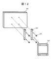
近年、液晶表示技術や周辺回路技術等の発展により、テレビ受像機等が薄型・軽量に製作できるようになったため、テレビを壁に取り付けることが可能になってきた。テレビを壁に取り付ける際には、壁に取り付け金具を取り付けたうえ、テレビ本体に取り付けた取り付け金具と組み合わせて壁に取り付ける形が一般的である。図12、図13は、壁取り付け金具を用いた取り付け構造の一例を示す図である。壁面Wに取り付ける取り付け金具303と、テレビ300とが、取り付け部材305とネジなどの固定具307により取り付けられている。
In recent years, with the development of liquid crystal display technology, peripheral circuit technology, and the like, television receivers and the like can be manufactured to be thin and light, so that it has become possible to attach a television to a wall. When mounting a TV on a wall, it is common to mount a mounting bracket on the wall and then mount it on the wall in combination with a mounting bracket mounted on the TV body. 12 and 13 are diagrams illustrating an example of a mounting structure using a wall mounting bracket. An attachment fitting 303 attached to the wall surface W and the
テレビを壁に取り付ける際、取り付け金具をテレビの背面に取り付けることにより正面からの見栄えを良くすることができるため、そのような構造をとるのが一般的であるが、構造上、テレビを薄型にしても取り付け金具の厚さ分だけ、テレビが壁から離れてしまい、テレビを薄型にすることのメリットが表れにくい。 When mounting the TV on the wall, it is common to use such a structure because it can improve the appearance from the front by attaching the mounting bracket to the back of the TV. However, the TV is separated from the wall by the thickness of the mounting bracket, and the merit of making the TV thinner is less likely to appear.
また、テレビのスピーカにおいて生じる振動がテレビ本体を振動させるが、スピーカから大きな音を出すとテレビが大きく振動してしまい、画質や音質に悪影響を及ぼす。振動が液晶パネルの劣化をもたらす可能性もある。特に、複数のスピーカユニットを取り付けたアレイスピーカを用いた場合には、振動板の合計質量が大きく、テレビ本体に伝わる振動が大きくなりがちである。
それゆえ、例えば、下記特許文献1に記載のように、振動の悪影響を避けるため、振動する部分に弾性材料を挿入することが一般的に行われている。
In addition, the vibration generated in the TV speaker vibrates the TV main body, but if a loud sound is produced from the speaker, the TV vibrates greatly, which adversely affects image quality and sound quality. The vibration may cause deterioration of the liquid crystal panel. In particular, when an array speaker having a plurality of speaker units is used, the total mass of the diaphragm is large, and the vibration transmitted to the television body tends to be large.
Therefore, for example, as described in
しかしながら、特許文献1のように、振動部分に弾性材料を用いると、弾性材料により支持される部分が振動しやすくなってしまうという問題がある。
例えば、スピーカボックスを、弾性材料を経由してシャーシに取り付ける場合、スピーカの振動板を振動させた反作用で振動するスピーカボックスが、弾性材料を用いない場合と比較して振動しやすくなり、音響の放射特性が劣るという問題がある。また、テレビに十分振動が伝わらないよう弾性材料をとりつけるとコスト高になるという問題もある。
本発明は、テレビを壁に取り付けた際の厚みを抑えること、スピーカの振動をテレビに伝えにくくすること、スピーカを壁に強固に取り付け、音質を改善することを目的とする。
However, like
For example, when the speaker box is attached to the chassis via an elastic material, the speaker box that vibrates due to the reaction of vibrating the speaker diaphragm becomes easier to vibrate compared to the case where no elastic material is used. There is a problem that radiation characteristics are inferior. In addition, there is a problem that the cost increases when an elastic material is attached so that the vibration is not sufficiently transmitted to the television.
An object of the present invention is to suppress the thickness when a television is attached to a wall, to make it difficult to transmit vibrations of the speaker to the television, and to firmly attach the speaker to the wall to improve sound quality.
本発明の一観点によれば、表示部を有する表示装置であって、前記表示装置の背面近傍の外縁から延び、係合孔を有し、前記係合孔を貫通して壁に固定するための取り付けネジにより前記表示装置を壁に固定する取付タブが設けられ、前記取付タブを収容する収容部を有するスピーカ部を前記取付タブと前記収容部との係合により固定する構造を有することを特徴とする表示装置が提供される。 According to one aspect of the present invention, there is provided a display device having a display unit, which extends from an outer edge in the vicinity of the back surface of the display device, has an engagement hole, passes through the engagement hole, and is fixed to a wall. There is provided a mounting tab for fixing the display device to the wall by a mounting screw, and a structure in which a speaker portion having a receiving portion for receiving the mounting tab is fixed by engagement of the mounting tab and the receiving portion. A display device is provided.
本発明によれば、表示装置を壁に取り付けた際の厚みを抑えることができる。また、スピーカの振動を表示装置に伝えにくくなり、画像に及ぼす影響を軽減することができる。さらに、スピーカを壁に強固に取り付けることができ、音質を改善することができる。 ADVANTAGE OF THE INVENTION According to this invention, the thickness at the time of attaching a display apparatus to a wall can be suppressed. Further, it becomes difficult to transmit the vibration of the speaker to the display device, and the influence on the image can be reduced. Furthermore, the speaker can be firmly attached to the wall, and the sound quality can be improved.
以下、本発明の実施の形態による表示装置について、壁取り付けテレビを例にして説明する。 Hereinafter, a display device according to an embodiment of the present invention will be described using a wall-mounted television as an example.
(第1の実施の形態)
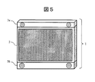
図1から図6までは、本実施の形態による壁取り付けテレビの構造を示す図であり、図1は正面図、図2は側面図であり、図3は分解斜視図であり、図4は取り付け後の側面図、図5は、取り付け後の正面図である。図6は、取り付け機構の詳細図である。
(First embodiment)
1 to 6 are views showing the structure of the wall-mounted television according to the present embodiment, FIG. 1 is a front view, FIG. 2 is a side view, FIG. 3 is an exploded perspective view, and FIG. FIG. 5 is a side view after attachment, and FIG. 5 is a front view after attachment. FIG. 6 is a detailed view of the attachment mechanism.
表示部2内に表示面を有する液晶パネル部201を有するテレビ1には、テレビ本体の上下に、例えば鉄製の取付タブ202a・202bが設けられている。テレビ1は壁に対して取付タブをネジ203によりネジ止めすることによって、壁に直に取り付けることができる。取付タブ202a・202bには、例えば、スピーカ部3a・3bが取り付け可能とされており、取付タブ202a・202bにかぶせる形にスピーカ部3a・3bが取り付けられる。取付タブ202a・202bは、取り付け後には、スピーカ部3a・3bにより覆われる。スピーカ部3a・3bにはスピーカユニットが設けられ、複数のスピーカユニットを並べたスピーカアレイを構成していても良い。図2は、テレビ断面を横からみた模式図である。図2から図4までに示すように、取付タブ202a・202bにはスピーカ取り付け台座としてはめ込み機構が取り付けられており、スピーカ部3a・3bを前記はめ込み機構にはめ込んで固定する。はめ込み機構は、取付タブ202a・202bとテレビ本体との表示面の法線方向の厚さの差に略対応する厚さを有するスピーカ部3a・3bにより、図4に示すように、固定される。ここでは、スピーカ部3a・3bの取り付けにより、スピーカ部3a・3bとテレビの面とが略同一面になっている。テレビの表示手段として液晶パネルを例に説明するが、表示手段を液晶パネルに限定するものではなく、プラズマディスプレイパネルや有機ELパネル等、あらゆる表示手段に応用可能であることはいうまでもない。
The
図6に示すように、はめ込み機構には、スピーカ部3(3a・3b)のガタつきを軽減するために、取付タブ202上にガスケット204が設けられており、スピーカ部3(3a・3b)と取付タブ202の機械的結合を強くしている。ガスケット204は、ゴム製のOリング等で構成されても良い。すなわち、表示装置の外縁から延びる方向に係合孔を有し、係合孔を貫通して壁に固定するための取り付けネジ203により表示装置を壁に固定する取付タブ202(202a・202b)が設けられている。そして、取付タブ202(202a・202b)を収容する収容部によりスピーカ部3(3a・3b)が固定されるようになっている。
As shown in FIG. 6, the fitting mechanism is provided with a
スピーカ部3(3a・3b)は、取付タブ202(202a・202b)にはめ込まれるため、スピーカ部3(3a・3b)で発生する振動は直に壁で受け止められ、テレビ本体に伝わる振動が軽減される。 Since the speaker unit 3 (3a and 3b) is fitted into the mounting tab 202 (202a and 202b), vibration generated in the speaker unit 3 (3a and 3b) is directly received by the wall, and vibration transmitted to the TV main body is reduced. Is done.
より具体的には、スピーカボックスに付加される質量が、スピーカボックスを弾性材料経由でシャーシに固定する方法では、スピーカボックスに付加される質量がわずかであるが、上記のように、スピーカボックスを壁面に取り付けた取付タブに取り付けると最大で壁の質量分となり、スピーカの振動板を駆動する駆動力の反作用に対して十分大きくなり、壁の質量分だけ重くなるためスピーカボックスの振動が十分小さくなり、より歪の少ない再生音を得ることができる。 More specifically, in the method in which the mass added to the speaker box is fixed to the chassis via the elastic material, the mass added to the speaker box is very small. When attached to a mounting tab attached to the wall surface, the maximum mass is the wall mass, which is sufficiently large against the reaction of the driving force that drives the diaphragm of the speaker, and heavier by the mass of the wall. Therefore, a reproduced sound with less distortion can be obtained.
液晶パネル部201は、取付タブ202(202a・202b)に対して弾性ブッシュ(弾性材料)206を経由して液晶パネル取り付けネジ205により取り付けられる。弾性材料206は取付タブ202(202a・202b)と液晶パネル部201との機械的結合を弱め、スピーカ部3(3a・3b)で発生した振動が液晶パネル部201に伝わりにくくする。従って、スピーカ部3(3a・3b)の振動による液晶パネル部201やバックライト・回路基板等のきしみや異音の発生を防止できるほか、振動による液晶の劣化等を防止することができる。
従って、壁面の強度が十分でなく、音圧等により振動したとしても液晶パネル部201に不具合が生じる可能性を低減することができる。
The liquid
Therefore, the strength of the wall surface is not sufficient, and even if the wall surface vibrates due to sound pressure or the like, it is possible to reduce the possibility that the liquid
尚、スピーカ部3(3a・3b)を取付タブ202(202a・202b)ではなく、はめ込み機構を設けたネジ203にはめ込む構造としても同等の効果が得られる。また、上記の例では、スピーカ部3(3a・3b)は取付タブ202(202a・202b)にはめ込まれるが、更に、固定ねじ等で取付タブ202(202a・202b)に固定するようにしても良い。
The same effect can be obtained even if the speaker unit 3 (3a, 3b) is fitted to the
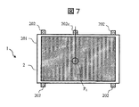
上下に取付タブ202(202a・202b)が取り付けてあるが、上下ともをスピーカ部3(3a・3b)を取り付ける必要はなく、いずれか一方でも良い。また、スピーカの取り付けられていない化粧カバーを取り付けても良い。取付タブは、複数の取付点それぞれ個別に液晶パネル部201に取り付けられても良いし、複数の取付点を持つシャーシ状の取付タブとしても良い。取付タブ202(202a・202b)は図では1辺に付き2個が設けられているが、2個に限らず、1辺に付き何点で固定してあっても良い。この際、図7に示すように、液晶パネル201及び取付タブ202a・202bを含めた表示部2の表示面に平行な鉛直線上であって表示部の上方の重心上の位置、すなわち、重心P1の真上に取付タブ202cを設置するとよい。このようにすることにより、重心の真上の取付タブ202cを最初に1点仮止めすることにより、表示部2の自重でバランスが取れ、その状態でテレビを壁に固定することにより、特別な道具を用いることなくテレビを水平に設置することができる。スピーカ部3(3a・3b)は、液晶パネル部201を固定したのちに設置する。
Although the mounting tabs 202 (202a and 202b) are mounted on the upper and lower sides, it is not necessary to mount the speaker unit 3 (3a and 3b) on the upper and lower sides, and either one may be used. Moreover, you may attach the decorative cover to which the speaker is not attached. The attachment tab may be individually attached to the liquid
以上に説明したように、本実施の形態によれば、表示装置の周囲に表示装置を壁に取り付けるための取付タブが設けられており、取付タブにスピーカ部を取り付ける構造であるため、表示装置を壁に取り付けた際の厚みを抑えることができる。
また、弾性部材を介して液晶パネルを取り付けることで、スピーカの振動を表示画面に伝えにくくなり、画像に及ぼす影響を軽減することができる。
As described above, according to the present embodiment, the mounting tab for mounting the display device to the wall is provided around the display device, and the speaker unit is attached to the mounting tab. The thickness when attached to the wall can be suppressed.
Further, by attaching the liquid crystal panel via the elastic member, it becomes difficult to transmit the vibration of the speaker to the display screen, and the influence on the image can be reduced.
(第2の実施の形態)
次に、本発明の第2の実施の形態について説明する。図8Aは、本実施の形態による表示装置の正面図であり、図8Bは、図8Aの取り付け方を示す分解斜視図である。図9は、スピーカ取り付け部断面を横からみた模式図である。図10は、本実施の形態による壁取り付けテレビの構造を示す側面図である。ここでは、主として第1の実施の形態との相違点について詳細に説明する。
(Second Embodiment)
Next, a second embodiment of the present invention will be described. FIG. 8A is a front view of the display device according to the present embodiment, and FIG. 8B is an exploded perspective view showing how to attach FIG. 8A. FIG. 9 is a schematic view of the cross section of the speaker mounting portion as viewed from the side. FIG. 10 is a side view showing the structure of the wall-mounted television according to the present embodiment. Here, differences from the first embodiment will be mainly described in detail.
本実施の形態のテレビ1には、左右に取付タブ202が取り付けられている。取付タブ202にはスピーカ取り付け台座としてフック207とストライク209とが取り付けてあり、スピーカ部3には、ピボットピン308とキャッチ310とが取り付けている。
Mounting
スピーカ部3の取り付けは、ピボットピン308を取付タブ202のフック207に引っかけ、ストライク209をキャッチ310に挿入する形で固定する。また、ピボットピン308とフック207とから構成されるヒンジ部付近に弾性材料212を設け、スピーカ部3の取付時に、ピボットピン308を中心とした回転運動により、弾性材料212が強く圧縮されることによりヒンジ部に定常的に力を加えるようにする。このようにすることにより、ピボットピン308やフック207の遊びによるガタつきやびびりを防止することができる。
The
また、ヒンジ部付近に電気接点を設けるとよい。スピーカ部3と表示部2の取り付けにかかわる位置決め精度に応じて接点位置が規定されるうえ、ヒンジ部付近に設けることにより接点圧力を高くとることができ、接触不良を低減することができる。接点は弾性材料212上に設けられても良い。弾性材料212は発砲ウレタンやゴムなどで構成されても良いが、金属バネ等を用い、接点として機能するようにしても良い。これらにより、スピーカ部3を電気的に接続する手間を省略することができ、誤接続の恐れを低減させることができる。
Further, an electrical contact may be provided near the hinge portion. The contact position is defined according to the positioning accuracy related to the attachment of the
以上に説明したように、本実施の形態によれば、表示装置の周囲に表示装置を壁に取り付けるための表示部の側部に位置する取付タブが設けられており、取付タブにスピーカ部を取り付ける構造であるため、表示装置を壁に取り付けた際の厚みを抑えることができる。
また、弾性部材を介して液晶パネルを取り付けることで、スピーカの振動を表示画面に伝えにくくなり、画像に及ぼす影響を軽減することができる。
As described above, according to the present embodiment, the mounting tab located on the side of the display unit for mounting the display device to the wall is provided around the display device, and the speaker unit is provided on the mounting tab. Since the structure is attached, the thickness when the display device is attached to the wall can be suppressed.
Further, by attaching the liquid crystal panel via the elastic member, it becomes difficult to transmit the vibration of the speaker to the display screen, and the influence on the image can be reduced.
(第3の実施の形態)
次に、本発明の第3の実施の形態について説明する。図11は、スピーカ取り付け部断面を横からみた模式図である。図11に示すように、スピーカ取り付け部は、スピーカ3のマグネット3111の漏洩磁束で取付タブ202に固定される。
(Third embodiment)
Next, a third embodiment of the present invention will be described. FIG. 11 is a schematic view of the cross section of the speaker mounting portion as viewed from the side. As shown in FIG. 11, the speaker mounting portion is fixed to the mounting
取付タブ202は鉄等の磁性材料で構成されており、スピーカユニット311を構成するマグネット3111の漏洩磁束によりスピーカユニット311と取付タブ202は吸着される。マグネットが取付タブ202側に設けられていても良い。
The mounting
テレビの上下取付タブを使わずにテレビを床置きするスタンドがあっても良い。その場合、上下取付タブと機械的に同一の構成部品に取り付けられる構成になっていれば同等の効果が得られる。 There may be a stand for placing the TV on the floor without using the TV's top and bottom mounting tabs. In that case, the same effect can be obtained as long as the upper and lower mounting tabs can be mechanically attached to the same component.
以上に説明したように、本実施の形態によれば、表示装置の周囲に表示装置を壁に取り付けるための表示部の側部に位置する取付タブが設けられており、取付タブにスピーカ部をマグネットで取り付ける構造であるため、ネジ等の固定具を用いて取付タブに固定する場合と比較して部品点数を削減できるほか、表示装置を壁に取り付ける作業が簡単である。 As described above, according to the present embodiment, the mounting tab located on the side of the display unit for mounting the display device to the wall is provided around the display device, and the speaker unit is provided on the mounting tab. Since the structure is attached with a magnet, the number of parts can be reduced as compared with the case of fixing to a mounting tab using a fixing tool such as a screw, and the work of attaching the display device to the wall is simple.
上記の実施の形態において、添付図面に図示されている構成等については、これらに限定されるものではなく、本発明の効果を発揮する範囲内で適宜変更することが可能である。その他、本発明の目的の範囲を逸脱しない限りにおいて適宜変更して実施することが可能である。 In the above-described embodiment, the configuration and the like illustrated in the accompanying drawings are not limited to these, and can be appropriately changed within a range in which the effect of the present invention is exhibited. In addition, various modifications can be made without departing from the scope of the object of the present invention.
また、本発明の各構成要素は、任意に取捨選択することができ、取捨選択した構成を具備する発明も本発明に含まれるものである。 Each component of the present invention can be arbitrarily selected, and an invention having a selected configuration is also included in the present invention.
また、本実施の形態で説明した機能を実現するためのプログラムをコンピュータ読み取り可能な記録媒体に記録して、この記録媒体に記録されたプログラムをコンピュータシステムに読み込ませ、実行することにより各部の処理を行ってもよい。尚、ここでいう「コンピュータシステム」とは、OSや周辺機器等のハードウェアを含むものとする。 In addition, a program for realizing the functions described in the present embodiment is recorded on a computer-readable recording medium, and the program recorded on the recording medium is read into a computer system and executed to execute processing of each unit. May be performed. The “computer system” here includes an OS and hardware such as peripheral devices.
また、「コンピュータシステム」は、WWWシステムを利用している場合であれば、ホームページ提供環境(あるいは表示環境)も含むものとする。 Further, the “computer system” includes a homepage providing environment (or display environment) if a WWW system is used.
また、「コンピュータ読み取り可能な記録媒体」とは、フレキシブルディスク、光磁気ディスク、ROM、CD−ROM等の可搬媒体、コンピュータシステムに内蔵されるハードディスク等の記憶装置のことをいう。さらに「コンピュータ読み取り可能な記録媒体」とは、インターネット等のネットワークや電話回線等の通信回線を介してプログラムを送信する場合の通信線のように、短時間の間、動的にプログラムを保持するもの、その場合のサーバやクライアントとなるコンピュータシステム内部の揮発性メモリのように、一定時間プログラムを保持しているものも含むものとする。また前記プログラムは、前述した機能の一部を実現するためのものであっても良く、さらに前述した機能をコンピュータシステムにすでに記録されているプログラムとの組み合わせで実現できるものであっても良い。機能の少なくとも一部は、集積回路などのハードウェアで実現しても良い。 The “computer-readable recording medium” refers to a storage device such as a flexible medium, a magneto-optical disk, a portable medium such as a ROM and a CD-ROM, and a hard disk incorporated in a computer system. Furthermore, the “computer-readable recording medium” dynamically holds a program for a short time like a communication line when transmitting a program via a network such as the Internet or a communication line such as a telephone line. In this case, a volatile memory in a computer system serving as a server or a client in that case, and a program that holds a program for a certain period of time are also included. The program may be a program for realizing a part of the above-described functions, or may be a program that can realize the above-described functions in combination with a program already recorded in a computer system. At least a part of the functions may be realized by hardware such as an integrated circuit.
本発明は、以下の開示を含む。
(付記)
本発明は、以下の開示を含む。
(1)表示部を有する表示装置であって、前記表示装置の背面近傍の外縁から延び、係合孔を有し、前記係合孔を貫通して壁に固定するための取り付けネジにより前記表示装置を壁に固定する取付タブが設けられ、前記取付タブを収容する収容部を有するスピーカ部を前記取付タブと前記収容部との係合により固定する構造を有することを特徴とする表示装置。
(2)前記取付タブは、前記表示部と弾性体を介して結合されていることを特徴とする(1)に記載の表示装置。
(3)前記取付タブを含めた前記表示部の重心を通る表示面に平行な鉛直線上であって表示部の上方の位置に、前記取付タブのうちの1つを設置することを特徴とする(1)又は(2)に記載の表示装置。
このようにすることにより、重心の真上の取付タブを最初に1点仮止めすることにより、表示部の自重でバランスが取れ、その状態でテレビを壁に固定することにより、特別な道具を用いることなくテレビを水平に設置することができる。スピーカ部は、表示部を固定したのちに設置する。
(4)前記スピーカ部には、磁石が設けられ、前記磁石の力により前記取付タブに吸着されることを特徴とする(1)から(3)までのいずれか1に記載の表示装置。
(5)前記スピーカ部の前記収容部に第1の電気接点が設けられており、前記スピーカ部の取り付けにより前記第1の接点と接触する前記取付タブの位置に第2の電気接点が設けられていることを特徴とする(1)から(4)までのいずれか1に記載の表示装置。
ヒンジ部付近に電気接点を設けると、スピーカ部と表示部の取り付けにかかわる位置決め精度に応じて接点位置が規定されるうえ、ヒンジ部付近に設けることにより接点圧力を高くとることができ、接触不良を低減することができる。
(6)前記取付タブには前記スピーカ取り付け台座としてフックとストライクとが取り付けられており、前記スピーカ部には、ピボットピンとキャッチとが取り付けられていることを特徴とする(5)に記載の表示装置。
スピーカ部の取り付けは、ピボットピンを取付タブのフックに引っかけ、ストライクをキャッチに挿入する形で固定することで、第1・第2の接点を接触させることができるようになっている。
(7)前記取付タブと前記スピーカ部との厚さの和が、前記表示装置の厚さとなっていることを特徴とする(1)から(6)までのいずれか1に記載の表示装置。
The present invention includes the following disclosure.
(Appendix)
The present invention includes the following disclosure.
(1) A display device having a display unit, the display device having an engagement hole extending from an outer edge in the vicinity of the back surface of the display device, and having an engagement hole for fixing to the wall through the engagement hole A display device comprising a mounting tab for fixing the device to a wall, and having a structure in which a speaker portion having a receiving portion for receiving the mounting tab is fixed by engagement of the mounting tab and the receiving portion.
(2) The display device according to (1), wherein the mounting tab is coupled to the display unit via an elastic body.
(3) One of the mounting tabs is installed on a vertical line parallel to a display surface passing through the center of gravity of the display unit including the mounting tab and above the display unit. The display device according to (1) or (2).
By doing so, the mounting tab just above the center of gravity is temporarily fixed at one point, so that the weight of the display unit can be balanced and the TV can be fixed to the wall in that state. The TV can be installed horizontally without using it. The speaker unit is installed after the display unit is fixed.
(4) The display device according to any one of (1) to (3), wherein the speaker unit is provided with a magnet and is attracted to the mounting tab by the force of the magnet.
(5) A first electrical contact is provided in the housing portion of the speaker unit, and a second electrical contact is provided at a position of the mounting tab that comes into contact with the first contact when the speaker unit is attached. The display device according to any one of (1) to (4), wherein:
If an electrical contact is provided near the hinge, the contact position is specified according to the positioning accuracy for mounting the speaker and display, and the contact pressure can be increased by providing it near the hinge, resulting in poor contact. Can be reduced.
(6) The display according to (5), wherein a hook and a strike are attached to the attachment tab as the speaker mounting base, and a pivot pin and a catch are attached to the speaker portion. apparatus.
The speaker portion can be attached by hooking the pivot pin on the hook of the attachment tab and fixing the strike by inserting it into the catch so that the first and second contacts can be brought into contact with each other.
(7) The display device according to any one of (1) to (6), wherein a sum of thicknesses of the mounting tab and the speaker portion is a thickness of the display device.
本発明は、表示装置に利用可能である。 The present invention is applicable to a display device.
1…テレビ、3a・3b…スピーカ部、201…液晶パネル部、202a・202b…取付タブ、203…ネジ、212…弾性材料、3111…マグネット。
DESCRIPTION OF
Claims (7)
前記表示装置を壁に固定するための固定具が貫通する係合孔を有する取付タブが設けられ、
前記取付タブは、前記取付タブを収容する収容部を有するスピーカ部を、前記取付タブと前記収容部との係合により固定する構造を有することを特徴とする表示装置。 A display device having a display unit,
A mounting tab having an engagement hole through which a fixture for fixing the display device to the wall is provided;
The display device according to claim 1, wherein the mounting tab has a structure in which a speaker portion having a storage portion for storing the mounting tab is fixed by engagement between the mounting tab and the storage portion.
前記取付タブを含めた前記表示部の重心を通り表示面に平行な鉛直線上であって表示部の上方の位置に、前記取付タブのうちの1つを設置することを特徴とする請求項1又は2に記載の表示装置。 A plurality of the mounting tabs are provided,
2. One of the mounting tabs is installed on a vertical line passing through the center of gravity of the display unit including the mounting tab and parallel to the display surface and above the display unit. Or the display apparatus of 2.
前記スピーカ部とThe speaker unit;
を備えていることを特徴とする表示システム。A display system characterized by comprising:
前記表示装置を壁に固定するための固定具が貫通する係合孔を有し、An engagement hole through which a fixture for fixing the display device to the wall passes;
前記取付タブを収容する収容部を有するスピーカ部を、前記取付タブと前記収容部との係合により固定する構造を有することを特徴とする取付タブ。An attachment tab having a structure in which a speaker portion having an accommodation portion for accommodating the attachment tab is fixed by engagement between the attachment tab and the accommodation portion.
Priority Applications (1)
| Application Number | Priority Date | Filing Date | Title |
|---|---|---|---|
| JP2013103213A JP6151086B2 (en) | 2013-05-15 | 2013-05-15 | Display device, display system and mounting tab |
Applications Claiming Priority (1)
| Application Number | Priority Date | Filing Date | Title |
|---|---|---|---|
| JP2013103213A JP6151086B2 (en) | 2013-05-15 | 2013-05-15 | Display device, display system and mounting tab |
Publications (3)
| Publication Number | Publication Date |
|---|---|
| JP2014225749A JP2014225749A (en) | 2014-12-04 |
| JP2014225749A5 JP2014225749A5 (en) | 2016-06-23 |
| JP6151086B2 true JP6151086B2 (en) | 2017-06-21 |
Family
ID=52124123
Family Applications (1)
| Application Number | Title | Priority Date | Filing Date |
|---|---|---|---|
| JP2013103213A Expired - Fee Related JP6151086B2 (en) | 2013-05-15 | 2013-05-15 | Display device, display system and mounting tab |
Country Status (1)
| Country | Link |
|---|---|
| JP (1) | JP6151086B2 (en) |
Families Citing this family (1)
| Publication number | Priority date | Publication date | Assignee | Title |
|---|---|---|---|---|
| JP2021192482A (en) | 2020-06-05 | 2021-12-16 | 船井電機株式会社 | Display device and display device speaker |
Family Cites Families (3)
| Publication number | Priority date | Publication date | Assignee | Title |
|---|---|---|---|---|
| JP3731531B2 (en) * | 2001-12-06 | 2006-01-05 | 株式会社ケンウッド | Speaker system and AV system using the speaker system |
| JP4784672B2 (en) * | 2009-01-22 | 2011-10-05 | ソニー株式会社 | Speaker mounting member for display device |
| US20120134519A1 (en) * | 2010-11-29 | 2012-05-31 | Caldes Douglas G | Integrated television Mount and Audio System |
-
2013
- 2013-05-15 JP JP2013103213A patent/JP6151086B2/en not_active Expired - Fee Related
Also Published As
| Publication number | Publication date |
|---|---|
| JP2014225749A (en) | 2014-12-04 |
Similar Documents
| Publication | Publication Date | Title |
|---|---|---|
| JP4808168B2 (en) | Display device | |
| JPWO2011074225A1 (en) | Speaker holding mechanism and television receiver including the same | |
| JP6354832B2 (en) | Microphone holding structure and electronic device | |
| KR100195535B1 (en) | Appartus for preventing picture vibration of image displayer | |
| JP2009259322A (en) | Display apparatus | |
| JP2011160319A (en) | Acoustic device and display device | |
| JP2014154922A (en) | Display device and television receiver | |
| JP6686117B1 (en) | Electronics | |
| US20070030993A1 (en) | Monitor apparatus | |
| JP4761561B2 (en) | Display device | |
| US9307327B2 (en) | Portable electroacoustic device | |
| JP6151086B2 (en) | Display device, display system and mounting tab | |
| JP3998618B2 (en) | Display device | |
| CN209435386U (en) | Audio frequency apparatus | |
| US11462199B2 (en) | Hybrid actuator and multimedia apparatus having the same | |
| JP5873747B2 (en) | Electronic device push button mounting structure | |
| JP2011182050A (en) | Video display device | |
| JP4789880B2 (en) | Door phone cordless handset device | |
| JP2013120970A (en) | Microphone attachment mechanism | |
| JP4538385B2 (en) | Portable electronic devices | |
| TWI479902B (en) | A horn mechanism and an electronic device with the horn mechanism | |
| JP2009232297A (en) | Display device | |
| US7251341B2 (en) | Microphone | |
| CN114025279B (en) | Flat plate sounding device and terminal equipment | |
| JP5191468B2 (en) | Speaker device, display device |
Legal Events
| Date | Code | Title | Description |
|---|---|---|---|
| A521 | Written amendment |
Free format text: JAPANESE INTERMEDIATE CODE: A523 Effective date: 20160428 |
|
| A621 | Written request for application examination |
Free format text: JAPANESE INTERMEDIATE CODE: A621 Effective date: 20160428 |
|
| RD02 | Notification of acceptance of power of attorney |
Free format text: JAPANESE INTERMEDIATE CODE: A7422 Effective date: 20160816 |
|
| RD04 | Notification of resignation of power of attorney |
Free format text: JAPANESE INTERMEDIATE CODE: A7424 Effective date: 20160822 |
|
| A977 | Report on retrieval |
Free format text: JAPANESE INTERMEDIATE CODE: A971007 Effective date: 20170117 |
|
| A131 | Notification of reasons for refusal |
Free format text: JAPANESE INTERMEDIATE CODE: A131 Effective date: 20170131 |
|
| A521 | Written amendment |
Free format text: JAPANESE INTERMEDIATE CODE: A523 Effective date: 20170403 |
|
| TRDD | Decision of grant or rejection written | ||
| A01 | Written decision to grant a patent or to grant a registration (utility model) |
Free format text: JAPANESE INTERMEDIATE CODE: A01 Effective date: 20170425 |
|
| A61 | First payment of annual fees (during grant procedure) |
Free format text: JAPANESE INTERMEDIATE CODE: A61 Effective date: 20170524 |
|
| R150 | Certificate of patent or registration of utility model |
Ref document number: 6151086 Country of ref document: JP Free format text: JAPANESE INTERMEDIATE CODE: R150 |
|
| LAPS | Cancellation because of no payment of annual fees |