JP6148577B2 - Imaging apparatus and control method - Google Patents
Imaging apparatus and control method Download PDFInfo
- Publication number
- JP6148577B2 JP6148577B2 JP2013171715A JP2013171715A JP6148577B2 JP 6148577 B2 JP6148577 B2 JP 6148577B2 JP 2013171715 A JP2013171715 A JP 2013171715A JP 2013171715 A JP2013171715 A JP 2013171715A JP 6148577 B2 JP6148577 B2 JP 6148577B2
- Authority
- JP
- Japan
- Prior art keywords
- correction amount
- amplification factor
- amount
- range
- dplus
- Prior art date
- Legal status (The legal status is an assumption and is not a legal conclusion. Google has not performed a legal analysis and makes no representation as to the accuracy of the status listed.)
- Expired - Fee Related
Links
Images


Landscapes
- Exposure Control For Cameras (AREA)
- Studio Devices (AREA)
Description
本発明は、撮像装置及び制御方法に関し、撮影対象に応じて撮影感度を制御することが可能な撮像装置及び制御方法に関する。 The present invention relates to an imaging apparatus and a control method, and more particularly to an imaging apparatus and a control method capable of controlling imaging sensitivity according to an imaging target.
従来、カメラにおいて被写体の明るさに応じて絞り値やシャッタ速度を調節して適切な露出で撮影を行う自動露出制御(AE)がある。このときAEでは、人物の顔の有無や逆光シーンであるか否かなど、さまざまな条件に応じて露出を決定する。 Conventionally, there is automatic exposure control (AE) in which shooting is performed with an appropriate exposure by adjusting an aperture value and a shutter speed in accordance with the brightness of a subject in a camera. At this time, in the AE, the exposure is determined according to various conditions such as the presence / absence of a person's face and whether it is a backlight scene.
画像内に明部と暗部が混在するコントラストのあるシーンの場合、明部に対して適正露出にすると暗部が黒つぶれし、暗部に対して適正露出にすると明部が白飛びしてしまうことがある。このようなコントラストのあるシーンは、絞り、シャッタ速度、ISO感度により決定される露出値だけで黒つぶれや白飛びを軽減した画像を得ることは難しい。 In the case of a scene with contrast in which bright and dark parts are mixed in the image, the dark part may be blacked out if the bright part is properly exposed, and the bright part may be blown out if the dark part is properly exposed. is there. In such a scene with contrast, it is difficult to obtain an image in which blackout or whiteout is reduced only by an exposure value determined by the aperture, shutter speed, and ISO sensitivity.
白飛び現象を軽減する手法として、ダイナミックレンジ(Dレンジ)補正撮影が知られている。これは、撮像素子の露光量を抑えて撮像することで白飛びが発生しないようにし、すでに適正な明るさになっていた領域や、暗部領域の明るさが不足した分は、ガンマカーブを調節することで白飛びのみを軽減する手法である。 As a technique for reducing the whiteout phenomenon, dynamic range (D range) correction photography is known. This is done by controlling the exposure amount of the image sensor to prevent the occurrence of overexposure, and adjusting the gamma curve for areas that have already been properly lit or the brightness of the dark areas is insufficient. This is a technique to reduce only the whiteout.
また、動きのある被写体の撮影時に速いシャッタ速度で撮影して被写体ブレを軽減したときに、ISO感度を向上させて被写体の明るさを補償する手法が知られている。 In addition, there is a known method for improving the ISO sensitivity and compensating for the brightness of a subject when the subject blur is reduced by photographing at a fast shutter speed when photographing a moving subject.
しかし、上述した画像処理によるDレンジ補正はS/N比の悪化が顕著になる場合があり、同じくS/N比の悪化の要因となるISO感度の増大と、共存することに課題があった。 However, the D range correction by the above-described image processing may cause a significant deterioration in the S / N ratio, and there is a problem in coexistence with an increase in ISO sensitivity that also causes a deterioration in the S / N ratio. .
特許文献1には、ノイズの増加を抑制しながら広ダイナミックレンジの画像を得るために、次の撮像装置が提案されている。すなわち、ISO感度範囲内でDレンジ補正可能なら補正し、ISO感度範囲内でDレンジ補正不可なら可能な範囲でISO感度を低減し、不足分は他の露出条件で補うものである。
しかしながら、上述した特許文献1ではDレンジ補正を優先し、目的のDレンジ補正を実現するためにISO感度や他の露出条件を使用するが、設定やシーンよっては、ISO感度を優先させた方がよい場合がある。
However, in
本発明は上記問題点を鑑みてなされたものであり、撮影するシーンや設定に応じて、適した感度の画像を得ることを目的とする。 The present invention has been made in view of the above problems, and an object of the present invention is to obtain an image with suitable sensitivity in accordance with a scene to be photographed and settings.
上記目的を達成するために、本発明の撮像装置は、被写体を撮影して、画像信号を出力する撮像手段と、測光手段と、前記画像信号の輝度分布を解析する解析手段と、前記画像信号を増幅する増幅手段と、画像信号に対するダイナミックレンジ制御を行う処理手段と、前記増幅手段における増幅率と、前記ダイナミックレンジ制御における補正量とのいずれを優先するかを判定する判定手段と、前記増幅率を優先する場合に、前記増幅率が取り得る値に対して前記補正量が取り得る値の範囲を制限し、前記補正量を優先する場合に、前記補正量が取り得る値に対して前記増幅率が取り得る値の範囲を制限する制限手段と、前記測光手段による測光の結果と、前記解析手段による解析の結果に基づいて、前記制限手段により制限された値の範囲で、前記増幅率及び前記補正量を決定する決定手段とを有する。 In order to achieve the above object, an imaging apparatus according to the present invention includes an imaging unit that captures an image of a subject and outputs an image signal, a photometric unit, an analysis unit that analyzes a luminance distribution of the image signal, and the image signal. and amplifying means for amplifying and processing means for dynamic range control against the images signals, and the amplification factor of the amplifying means, determination means for determining one or priority of the correction amount in the dynamic range control, When giving priority to the amplification factor, the range of values that the correction amount can take is limited to the value that the amplification factor can take, and when giving priority to the correction amount, the value that the correction amount can take A range of values limited by the limiting unit based on a result of photometry by the photometric unit and a result of analysis by the analyzing unit. , And a determination means for determining the amplification factor and the correction amount.
本発明によれば、撮影するシーンや設定に応じて、適した感度の画像を得ることができる。 According to the present invention, an image with suitable sensitivity can be obtained according to the scene to be photographed and the setting.
以下、添付図面を参照して本発明を実施するための最良の形態を詳細に説明する。 The best mode for carrying out the present invention will be described below in detail with reference to the accompanying drawings.
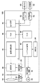
図1は、本実施形態における撮像装置100の概略構成を示すブロック図である。
FIG. 1 is a block diagram illustrating a schematic configuration of an
レンズユニット10は複数のレンズにより構成され、メカ駆動回路14によりレンズユニット10の一部または全部を光軸方向に沿って駆動することで、焦点や画角を調節することができる。また、カメラブレに応じてレンズユニット10の一部を光軸方向以外にも駆動することで手ぶれ補正を行うことも可能である。なお、手ぶれ補正は撮像部20を動かすことでも同様に実現可能である。レンズユニット10を通過した光は光量調節機構12によりその光量を調節することができる。光量調節方法しては、口径を変化させる光彩絞りや、光透過量を落とすNDフィルター、開閉により光を通過/遮光するメカシャッタなど様々な形態があり、用途に応じて使い分ける。
The
レンズユニット10及び光量調節機構12を通過した光は撮像部20で受光される。撮像部20は撮像駆動回路22からの駆動指示により動作し、CCDやCMOSセンサ等に代表される撮像素子における電荷蓄積、蓄積された電荷の読み出し、読み出した電荷(画像信号)の増幅/減衰、画像信号のA/D変換などを行う。撮像部20から出力された画像データは画像処理回路40に入力されるか、あるいは一時記憶メモリ(RAM)46に記憶される。
The light that has passed through the
画像処理回路40は、撮像部20から直接、あるいは一時記憶メモリ46を経由して入力された画像データの画像処理や画像解析など様々な処理を行う。まず、撮影時の自動露出制御(AE:AutoExposure)や自動焦点調節(AF:AutoFocus)では、撮像部20から順次出力される画像データから輝度成分や周波数成分を抽出し、これらを評価値として用いることでAE、AFを行うことができる。また、画像処理回路40は撮像部20から得た画像データを現像処理して画質を調節することができ、色合い、階調、明るさ等を適切に設定して鑑賞に適した写真に仕上げる。
The
さらに画像処理回路40は、入力された画像内から、例えば人物の顔等の被写体を検出することができ、画像内における人物の顔の位置、大きさ、傾き、顔の確からしさ情報等を得ることができる。また、検出した人物の顔の特徴情報を抽出し、特定の個人であるかを認証することができる。認証にあたっては、ROM48に記憶されている個人の特徴情報を読み出し、画像処理回路40で特徴情報を比較して一致処理を行い、登録済みの個人と一致するかを確認する。また、画像処理回路40は人物の顔の詳細な解析を行うことができ、例えばその人物の眼を解析して視線方向を検出することができる。
Further, the
さらに画像処理回路40は、連続して入力された画像間の被写体の位置の変化に基づいて被写体の動き量を算出する。
Further, the
LCDなどの表示装置50は、画像処理回路40で現像処理された画像を表示したり、また、文字やアイコンを表示することで使用者に対して情報伝達をすることもできる。撮像部20により所定周期で得られた画像を表示することにより、電子ビューファインダ(EVF)として用いることができる。
The
また、撮像装置100に対し、外部メモリI/F52を介して外部メモリ90を挿入したり、外部機器I/F54を介して外部機器92を接続することができる。外部メモリ90や外部機器92を接続することで、画像の授受や互いの機器を動作させるコマンド情報などをやりとりすることができる。
Further, the
システム制御部42は、撮像装置100の各構成を制御し、使用者は操作部44を介して動作の指示を入力することができる。フラッシュ30は発光制御回路32からの指示により、主被写体に向けて発光することで、主被写体が暗い場合にフラッシュ30を発光させることで十分な光量を得ることができ、暗い中でも速いシャッタ速度を保ち、好適な画像を得ることができる。
The
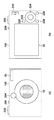
図2は、撮像装置100の外観の一例を示す概略図であり、図2(a)は前面、図2(b)は裏面を示している。撮像装置100の前面にはレンズユニット10が配置され、同一面にフラッシュ30が配置されている。また、図2(b)には示していないが、従来からの光学ファインダ204を併設する構成とすることも可能である。表示装置50に撮像部20から得られる画像を逐次表示するEVFは、高い視野率を実現し易い、表示装置50の大きさによっては被写体が大きく見易い、撮影画像とファインダ画像の画角差(パララックス)が無い、などのメリットがある。その反面、撮像素子や表示装置50を動作させるための電力が必要となり、電池の消耗が早くなることが懸念される。このため、電池の消耗を避けて多くの撮影枚数が望まれる場合には、電子ビューファインダー機能をOFFにし、光学ファインダ204を使用することができる。
2A and 2B are schematic diagrams illustrating an example of the appearance of the
また、裏面には表示装置50が配置されている。また、撮像装置100の複数の位置には位置された操作部材210、220、222、224、226、228を操作することで、撮影モード切り替え、各種設定等、ユーザー操作に応じた機能が発動する。
A
撮像装置の上部には、電源ON/OFFスイッチ200、シャッタスイッチ202が配置されている。シャッタスイッチ202を浅く押下する(SW1)ことで撮影の準備、ボタンを深く押下することで撮影の開始を指示する。
A power ON /
次に、上記構成を有する撮像装置100における撮影時の露出及びダイナミックレンジ(Dレンジ)補正の決定方法について説明する。露出を決定する要素は、被写体輝度Bv、撮影感度Sv、絞り値Av、シャッタ速度Tvである。フィルムカメラの場合、撮影感度Svは装填するフィルムによって決定され、測光センサにより被写体輝度Bvを測定し、露出値Evを式(1)により算出することができる。
Bv+Sv=Ev …(1)
式(1)により算出された露出値Evはその被写体を適正露出で撮影するための目標値となり、このEvを実現する絞り値Avとシャッタ速度Tvの組み合わせを決定する。
Ev=Av+Tv …(2)
Next, a method for determining exposure and dynamic range (D range) correction during shooting in the
Bv + Sv = Ev (1)
The exposure value Ev calculated by the equation (1) is a target value for photographing the subject with appropriate exposure, and determines the combination of the aperture value Av and the shutter speed Tv that realizes this Ev.
Ev = Av + Tv (2)
デジタルカメラの場合も基本的には式(1)、式(2)を用いて露出を決定するが、フィルムカメラと大きく異なるのは、撮影感度Svを動的に変更することが可能な点である。 Even in the case of a digital camera, the exposure is basically determined by using the equations (1) and (2). However, the difference from the film camera is that the photographing sensitivity Sv can be dynamically changed. is there.
図3は、露出及びゲインにより撮影した画像の明るさを調節する処理の概念を示す図である。被写体像がレンズユニット10を通過する際、絞り値Av303により光量がコントロールされ、撮像素子にて受光される。受光時間はシャッタ速度(電荷蓄積時間)Tv305にてコントロール可能な構成となっている。撮像部20の撮像素子にて光電変換される際、この特性により基本感度BaseSv307が決定される。撮像素子から読み出された画像データは、アナログゲインアンプ309にてゲインがかけられる。このアナログゲインアンプ309は任意の値を指定することができ、撮影感度を調節する機能の実現手段として使用可能である。式(1)と式(2)に自動感度制御の概念を加えると以下の式(3)となり、絞り値とシャッタ速度とゲイン値によって目標Evとなるように動作させることができる。
Bv+BaseSv=Ev=Av+Tv−DeltaGain …(3)
このときの最終的な感度は、
Sv=BaseSv+DeltaGain …(4)
となり、式(3)は式(5)で表現することができる。
Bv+Sv=Ev=Av+Tv …(5)
FIG. 3 is a diagram illustrating a concept of processing for adjusting the brightness of an image captured by exposure and gain. When the subject image passes through the
Bv + BaseSv = Ev = Av + Tv−DeltaGain (3)
The final sensitivity at this time is
Sv = BaseSv + DeltaGain (4)
Equation (3) can be expressed by Equation (5).
Bv + Sv = Ev = Av + Tv (5)
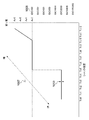
図10に、露出値Evに応じた絞り値、シャッタ速度、感度の組み合わせを表現したプログラム線図を示す。横軸はシャッタ速度Tv、縦軸は絞り値Avを表し、各露出値Ev1007に対応する組み合わせが表現されている。図10では一例として、絞り値が開放(図ではAv3)になった以降は感度1005を上げて低輝度被写体に追従する例を示している。最高感度をどこまで上げるかを示す矢印1013に関してはこのプログラム線図で表現することができ、製品仕様に合わせて設計を行う。
FIG. 10 shows a program diagram expressing combinations of aperture value, shutter speed, and sensitivity according to the exposure value Ev. The horizontal axis represents the shutter speed Tv, the vertical axis represents the aperture value Av, and a combination corresponding to each exposure value Ev1007 is represented. As an example, FIG. 10 shows an example in which the
図3に戻り、絞り値Av、シャッタ速度Tv、感度Sv(=BaseSv+DeltaGain)によってアナログでの信号レベルが決定されたのち、A/D変換が行われる。このあと、画像処理回路40において、デジタル的な信号変換としてDeltaDP(DPlus量)313をかけることができる。この変換ではガンマカーブにより入力信号対出力信号の変換方法を表現することができ、図4にその概念図を示す。横軸は入力信号、縦軸は出力信号を示し、入力信号のレベル毎に変換後の値を定義することができる。例として、入力信号対出力信号の変換特性を2種類示す。図4から分かるように変換特性413は、変換特性411に対してゲインアップ量が高い。また、変換特性413の暗部は変換カーブがより垂直に立っているため、変換特性411よりも変換後の諧調性が損なわれる。このように、変換カーブ特性により、どの入力信号レベルにどの程度の諧調性を持たせるかを調節できるため、絞り、シャッタにより撮像素子にどの程度の露光量を確保するかと合わせて、画像のダイナミックレンジを制御することが可能となる。
Returning to FIG. 3, the analog signal level is determined by the aperture value Av, the shutter speed Tv, and the sensitivity Sv (= BaseSv + DeltaGain), and then A / D conversion is performed. Thereafter, the
上記で述べた、絞り値、シャッタ速度、ゲイン、ガンマカーブを、被写体に応じてどのように設定すれば効果的かを、図5、図6、図7を例に説明する。 How the aperture value, shutter speed, gain, and gamma curve described above are effectively set according to the subject will be described with reference to FIGS. 5, 6, and 7 as an example.
図5は、被写体の動き量が異なるシーンの例を示す図であり、図5(a)は静止している人物を撮影する例を示している。これに対し、図5(b)は走っている人物を撮影する例を示している。動いている被写体を撮影する際、遅いシャッタ速度で撮影すると人物のブレが目立ちやすくなるため、速いシャッタで撮影したほうが良好な写真が得られるケースが多い。被写体輝度にもよるが、速いシャッタ速度で撮影するためにはそれを補うために感度も上げて撮影する必要がある。一方、静止している被写体はブレが少ないため、遅めのシャッタ速度かつ低感度で撮影することで良好な画質を得ることができる。 FIG. 5 is a diagram showing an example of a scene in which the amount of movement of the subject is different, and FIG. 5A shows an example of photographing a stationary person. On the other hand, FIG. 5B shows an example of photographing a running person. When shooting a moving subject, it is more likely that a person will be blurred when shooting at a slow shutter speed. Although depending on the subject brightness, in order to shoot at a fast shutter speed, it is necessary to shoot with increased sensitivity to compensate for it. On the other hand, since a stationary subject has less blur, good image quality can be obtained by shooting with a slow shutter speed and low sensitivity.
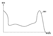
図6はいずれも静止している人物を撮影する例を示しているが、背景の様子(明るさ)が異なる。図6(a)は背景が一様な明るさであるのに対し、図6(b)は、画面下部が暗く、上部が明るい明暗差のあるシーンを示している。図6(a)、(b)を同一の露出で撮影した場合、図6(b)の明るい背景が白とびしやすくなる現象が発生する懸念がある。このため、図6(b)の撮影時には撮像素子の露光量を低く抑えることで白とびを抑え、露出を低く抑えた分を補うようにガンマカーブで調節するように撮影すると、白飛びの軽減を期待することができる。図6(b)のようなシーンの輝度ヒストグラムをみると図9に示すように、高輝度領域と低輝度領域に画素が多く分布し、輝度コントラストがある傾向がみられる。輝度コントラストがあり、ダイナミックレンジ制御が有効なシーンであるか否かは、このように輝度ヒストグラムを参照する方法が有効である。 FIGS. 6A and 6B show examples of photographing a still person, but the background (brightness) is different. FIG. 6A shows a scene with a uniform brightness, while FIG. 6B shows a scene where the lower part of the screen is dark and the upper part has a bright contrast. When shooting in FIGS. 6A and 6B with the same exposure, there is a concern that a phenomenon that the bright background in FIG. For this reason, at the time of shooting in FIG. 6B, the overexposure is suppressed by suppressing the exposure amount of the image sensor to a low level, and shooting is performed by adjusting the gamma curve so as to compensate for the low exposure. Can be expected. When the luminance histogram of the scene as shown in FIG. 6B is seen, as shown in FIG. 9, a large number of pixels are distributed in the high luminance region and the low luminance region, and there is a tendency that there is luminance contrast. The method of referring to the brightness histogram is effective for determining whether or not the scene has brightness contrast and dynamic range control is effective.
図7は、明暗差のある背景の中を走っている被写体の例を示す。このような場合、被写体のブレを軽減するために感度をあげて速いシャッタ速度で撮影することが望まれると共に、明暗差を解消するためにダイナミックレンジを制御することも望まれる。しかしながら、ダイナミックレンジを稼ぐために図3に示すようなガンマカーブをかける場合、ノイズ成分が増加して画質的な劣化が懸念され、被写体のブレ軽減と、良好な画質の両立が課題となる。 FIG. 7 shows an example of a subject running in a background with a contrast difference. In such a case, it is desired to increase the sensitivity in order to reduce the blurring of the subject and take a picture with a high shutter speed, and it is also desirable to control the dynamic range in order to eliminate the difference in brightness. However, when a gamma curve as shown in FIG. 3 is applied in order to increase the dynamic range, the noise component increases and there is a concern about image quality deterioration, and there is a problem in reducing both subject blurring and good image quality.
そのような課題に対する例として、図8(a)及び(b)は被写体の動き量に応じて撮影パラメータを決定する方法の概念を示している。図8(a)において、横軸が被写体の動き量、縦軸が最大感度を表し、図8(b)では、横軸が被写体の動き量、縦軸が最大Dレンジ補正量を示している。被写体の動きが小さい場合、最大感度をISO3200に制限するとともに、最大Dレンジ補正量を400%まで可能とすることで、ISO感度アップによる画質劣化分をDレンジ補正に割り当てて使用することができる。一方、被写体の動き量が大きい場合、最大感度をISO12800まで許可して被写体のブレが軽減される効果を狙うとともに、Dレンジ補正による画質劣化がこれ以上発生しないようにDレンジ補正を行わないパラメータ設計としている。
As an example for such a problem, FIGS. 8A and 8B show the concept of a method for determining a shooting parameter in accordance with the amount of movement of a subject. 8A, the horizontal axis represents the amount of movement of the subject, and the vertical axis represents the maximum sensitivity. In FIG. 8B, the horizontal axis represents the amount of movement of the subject, and the vertical axis represents the maximum D range correction amount. . When the movement of the subject is small, the maximum sensitivity is limited to
これまで述べたように、シーンによって適切な絞り値、シャッタ速度、ゲイン、ガンマカーブは異なるため、適応的に値をとることで、よりダイナミックレンジが広く、画質劣化を抑えた撮影を行うことができる。一つの方法として、ユーザーが任意のISO感度値やDレンジ補正値を選択可能な仕様としてもよい。また、感度向上を優先的に行うモードA、Dレンジ補正を優先的に行いモードB、というふうに、カメラが自動で露出を決定し、その決定の際に優先すべき項目を指定する搭載形態としてもよい。 As described so far, the appropriate aperture value, shutter speed, gain, and gamma curve differ depending on the scene. it can. As one method, the user may select an arbitrary ISO sensitivity value or D range correction value. In addition, the camera automatically determines the exposure and designates the item to be prioritized in the determination, such as mode A in which sensitivity improvement is prioritized and mode B in which D range correction is prioritized. It is good.
次に、図11、図12、図13を参照しながら、上記構成を有する撮像装置100の本実施形態における動作について説明する。また、図14〜図19に、Dレンジ補正設定とISO感度(増幅率)設定の組み合わせを表で示す。
Next, the operation in the present embodiment of the
図11は、本実施形態の撮像装置100における撮影処理を示すフローチャートである。この処理は図2で示した撮像装置100の電源ON/OFFスイッチ200がオンされると開始される。S103でシステム起動を行う。ここでは撮像装置100が動作するのに必要なCPUやLSIへの電源供給、クロック供給をはじめ、メモリやOSの初期化など、基本システムの起動が行われる。
FIG. 11 is a flowchart illustrating a shooting process in the
次に、S105において撮像部20内の撮像素子等、撮像系の起動や、フォーカスレンズやズームレンズ等を含むレンズユニット10等、光学系の起動が行われる。更に、メカシャッタやメカ絞りが動作し、撮像素子に外光が導かれ始める。続いて、S107では、画像処理回路40において、撮像素子から読み出したデータを元に、明るさ、色、ピント状況を計測し、それぞれを好適な状態にするAE、AF、AWB処理が開始される。AE、AF、AWB処理が起動したあと、S109においてEVF用の画像の生成を開始する。ここで生成されたEVF用の画像は表示装置50に表示される一方、S111において、顔検出、個人認証、視線検出などの検出系処理にも使用される。起動が完了したのち、EVF表示の定常状態に入る。
Next, in S105, an imaging system such as an imaging element in the
EVF表示の定常状態において、S113でシステム制御部42は撮影準備指示ボタンとしてSW1がONされたかどうかを判断する。ONされていなければEVF表示を継続し、ONされるとS201へ進む。S201では、ISO感度とDレンジ補正のいずれを優先するかを示す優先モード判定や、ISO感度及びDレンジ補正量(DPlus)の制御範囲が決定される。なお、S201で行われる処理の詳細に関しては図12を参照して後述する。そして、S301で撮影用の露出を決定するAE処理及びDレンジ補正量の決定を行い、S115で合焦制御のためのAF処理が行われる。なお、S301における処理の詳細に関しては、図13を参照して後述する。
In the steady state of EVF display, in S113, the
撮影条件が決定したのち、S117において、システム制御部42はSW2がONされたかどうかを判断する。ONされていなければ、S118でSW1がONされたままかどうかを判断し、ONされていればS117の処理を繰り返し、ONされていなければ、S113に戻って上記処理を繰り返す。一方、SW2がONされるとS119に進み、予め決められた露出条件に従って撮影が行われ、撮影が終了すると、S120においてシステム制御部42はSW2がOFFされるのを待ち、S113に戻って上記処理を繰り返す。なお、連写の場合には、S119で撮影した後、S120ではなく、S117に戻る。
After the shooting conditions are determined, in S117, the
次に図12を参照して、S201で行われるISO感度とDレンジ補正のいずれを優先するかを示す優先モード判定、及び、ISO感度及びDレンジ補正量の制御範囲を決定する処理について説明する。 Next, with reference to FIG. 12, the priority mode determination indicating which of the ISO sensitivity and D range correction to be prioritized performed in S201 and the process of determining the control range of the ISO sensitivity and the D range correction amount will be described. .
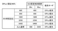
まず、S203において、図14に示す表に従い、システム制御部42はDPlus設定に応じてDPlus制御範囲及び優先モードを決定する。DPlusとしては、例えば図4に示す例では、DPlus量が400%、DPlus制御範囲の値2は変換特性413に対応し、DPlus量が200%、DPlus制御範囲の値1は変換特性411に対応する。また、DPlus量がOFF、DPlus制御範囲の値0は図4において点線で示す特性(即ち、入力信号=出力信号)に対応する。図14に示す例では、ユーザーがDPlus設定を、OFF/固定200%/固定400%/Autoの4種類の中から選べることを前提としている。選択されたDPlus設定に応じて、DPlus制御範囲と優先モードが決定される。OFFの場合はDPlus制御範囲は最小(Min)0〜最大(Max)0となり、事実上DPlusが機能しないことを示している。このとき、優先モードはISO感度優先モードとなり、ISO感度決定を優先的に行うことを示している。DPlus固定200%/400%は、それぞれDPlus制御範囲はMin1〜Max1、Min2〜Max2となり、事実上DPlusがその固定量だけかかることを示している。なお、表ではDレンジ補正200%を1段、400%を2段として数値で表現している。DPlus設定Autoは後述する図18に示す表に従う。
First, in S203, the
続いて、S205においてシステム制御部42はISO感度制御範囲を決定するが、DPlus設定に応じてどの表に従うかを判定する。DPlus設定がOFF/200%/400%/Autoの4種類のいずれかに応じて、それぞれ対応する表を参照するS211、S221、S231のいずれかに進む。
Subsequently, in S205, the
DPlus設定がOFFの場合、S211に進み図15に示す表に従う。表は選択可能なISO感度それぞれに応じて、ISO感度制御範囲と優先モードを表している。DPlusがOFF設定の場合、最低感度も最高感度も制限を受けないため、この撮像装置100の最低感度及び最高感度であるISO100〜12800の範囲でISO固定設定が選択できる。例ではISOAuto設定として2種類選択可能な形態を示している。Auto通常はISO100〜3200、Auto拡張はISO100〜12800の範囲で自動的に感度を選択できる。Auto通常はISO感度アップによる画質劣化を考慮して、最高感度を抑えているモードである。一方、Auto拡張は画質劣化をいとわず、そのカメラの最高感度まで感度アップするモードである。
If the DPlus setting is OFF, the process proceeds to S211 and follows the table shown in FIG. The table shows the ISO sensitivity control range and priority mode for each selectable ISO sensitivity. When DPlus is set to OFF, neither the minimum sensitivity nor the maximum sensitivity is limited. Therefore, the ISO fixed setting can be selected within the range of
DPlusが200%の場合、S221に進み図16に示す表に従う。表ではISO感度の最低値がISO200になっており、ISO100が実現できないことを示している。これは、DPlus200%を実現するにあたり、すでに感度が1段上がった状態であるためである。また、ISO感度の最高値がISO6400になっているが、これは画質劣化を懸念して、ISO感度を6400までしか上げないことを示している。ここで、実現できないISO感度が設定されないように、使用者が操作部44を介してISO100及びISO12800を設定できないようにしている。図16に示す表ではISOAutoの感度制御範囲も制限されている。同様の理由で、DPlus設定がOFFの場合と比べて、感度最低値がISO200となると共に、ISOAuto拡張の感度最大値がISO6400に下げられている。また、DPlus200%では、優先モードはいずれもDPlus優先となっており、DPlus200%を優先して実現することを示している。
When DPlus is 200%, the process proceeds to S221 and follows the table shown in FIG. The table shows that the lowest ISO sensitivity is ISO200, and ISO100 cannot be realized. This is because the sensitivity has already been increased by one step in realizing
DPlusが400%の場合、S221に進み図17に示す表に従う。考え方は図16に示したDPlus200%と同様で、最低感度、最高感度が制限を受けている。優先モードはDPlus実現を優先するモードである。なお、DPlusが400%の場合、ISOAutoの最高値はISO3200に制限されるため、Auto通常とAuto拡張とで感度制御範囲は等しくなる。すなわち、DPlusが400%の場合、Auto通常とAuto拡張の区別がなくなるため事実上Auto拡張は機能せず、図17に示す表にはAuto拡張は記載されていない。DPlusが400%の場合もDPlusが400%の場合と同様に、実現できないISO感度が設定されないように、使用者が操作部44を介してISO100、ISO200及びISO12800を設定できないようにしている。さらに、事実上機能しないAuto拡張も設定できないようにしている。
When DPlus is 400%, the process proceeds to S221 and follows the table shown in FIG. The idea is the same as DPlus200% shown in FIG. 16, and the minimum sensitivity and the maximum sensitivity are limited. The priority mode is a mode that prioritizes DPlus implementation. When DPlus is 400%, the maximum value of ISOAuto is limited to ISO3200, so the sensitivity control range is the same for Auto normal and Auto expansion. That is, when DPlus is 400%, there is no distinction between Auto normal and Auto extension, so the Auto extension does not function effectively, and the table shown in FIG. 17 does not describe the Auto extension. Similarly to the case where DPlus is 400%, similarly to the case where DPlus is 400%, the user cannot set ISO100, ISO200, and ISO12800 via the
DPlusがAutoの場合、S231に進み図18に示す表に従う。DPlusがAutoで、かつISO感度が固定設定の場合、ユーザーが選択したISO感度を実現することを優先する。このとき、ISO400〜3200は、最低感度保障としても、画質保障としてもDPlus400%を実現することができ、DPlus制御範囲は0〜2段となっている。これに対し、ISO200ではDPlusを1段しかかけることができないため、DPlus制御範囲は0〜1段となり、ISO100ではDPlusをかけることができないため、DPlus制御範囲は0〜0となりDPlusをかけることができない。一方、高感度側はISO6400では画質劣化を考慮してDPlus制御範囲を0〜1段に抑え、ISO12800ではDPlusがかからないように制御範囲を0〜0段に設定している。
When DPlus is Auto, the process proceeds to S231 and follows the table shown in FIG. When DPlus is Auto and ISO sensitivity is fixed, priority is given to realizing the ISO sensitivity selected by the user. At this time, ISO400 to 3200 can realize DPlus400% as the minimum sensitivity guarantee and the image quality guarantee, and the DPlus control range is 0 to 2 steps. On the other hand, because ISO200 can only apply 1 step of DPlus, the DPlus control range is 0 to 1 step, and ISO100 cannot apply DPlus, so the DPlus control range is 0 to 0 and DPlus can be applied. Can not. On the other hand, on the high sensitivity side, the
DPlusAutoとISOAuto通常の組み合わせは、DPlusを優先するモードとする。このとき表では、ISO感度範囲がISO100〜3200となっており、DPlusがかかったときに最低ISO感度を実現できない範囲になっているが、これは後述する図13のフローチャートに従って決定する。 The normal combination of DPlusAuto and ISOAuto is the mode that prioritizes DPlus. At this time, in the table, the ISO sensitivity range is ISO100 to 3200, and the range where the minimum ISO sensitivity cannot be realized when DPlus is applied is determined according to the flowchart of FIG.
DPlusAutoとISOAuto拡張の組み合わせは、ISO感度を優先するモードとする。このとき表では、DPlus制御範囲が0〜2となっており、ISO感度が所定より低い場合や高い場合にDPlusを実現できない範囲になっているが、これは後述する図13のフローチャートに従って決定する。 The combination of DPlusAuto and ISOAuto expansion is a mode that prioritizes ISO sensitivity. At this time, in the table, the DPlus control range is 0 to 2, which is a range where DPlus cannot be realized when the ISO sensitivity is lower or higher than a predetermined value, but this is determined according to the flowchart of FIG. .
DPlusAutoとISOAuto適応の組み合わせは、被写体の状況に応じて優先モードを切り替え可能な形態としている。これを図19に示す表を用いて説明する。図19に示す表は、図5、図6、図7に示したように被写体が動いている場合と画面内に明暗差がある場合を考慮して、適応的に制御範囲を決定する例を示している。表では被写体の動き量を大中小として検出した結果を用い、各制御範囲と優先モードを決定するものとしている。 The combination of DPlusAuto and ISOAuto adaptation allows the priority mode to be switched according to the subject's situation. This will be described with reference to the table shown in FIG. The table shown in FIG. 19 is an example in which the control range is adaptively determined in consideration of the case where the subject is moving and the case where there is a light / dark difference in the screen as shown in FIGS. Show. In the table, each control range and priority mode are determined using the result of detecting the amount of movement of the subject as large, medium and small.
このように、DPlusがAutoの場合、システム制御部42はS231の後にS233においてISOAuto適応か判定して、ISOAuto適応でなければS201の処理を終了し、ISOAuto適応であればS235に進む。
As described above, when DPlus is Auto, the
S235では、システム制御部42は、画像処理回路40にて算出された被写体の動き量を判定をして、S237では算出された動き量と図19に示す表とに基づいて、ISO制御範囲、DPlus制御範囲、優先モードが決定される。
In S235, the
被写体の動き量が小さい場合、被写体ブレを軽減するために極端に感度を上げる必要がないため、ISO制御範囲はISO100〜3200としている。DPlus制御範囲は0〜2段まで可能としてDPlus優先とすることで、明暗差を軽減することを優先するモードとしている。被写体の動き量が中程度の場合、ISO制御範囲をISO100〜6400とし、比較的被写体ブレに強くし、ISO感度が上がることに伴ってDPlus制御範囲を狭くして画質劣化が顕著にならないようにしている。被写体の動き量が大きい場合、被写体ブレを軽減することを最優先とし、ISO感度制御範囲は最高感度をISO12800としている。また、優先モードはISO感度優先としてブレ軽減に重点を置いている。このように、表に従ってISO感度制御範囲、DPlus制御範囲、優先モードが決定される。
When the amount of movement of the subject is small, the ISO control range is set to
次に図13を参照して、図11のS301で行われる撮影用の露出を決定する処理について説明する。まずS303において、システム制御部42はDPlus設定に応じてDPlus量(ダイナミックレンジ制御の補正量)としてすでにユーザーにより固定値が選択されているか、または、撮像装置が自動的に選択するAutoなのかを判定する。DPlus量として固定値が選択されている場合、S305において、選択されている固定値を確定する。
Next, with reference to FIG. 13, the process for determining the exposure for photographing performed in S301 of FIG. 11 will be described. First, in step S303, the
一方、DPlus設定がAutoの場合、S307において、画像処理回路40はシーンに応じたDPlus量を算出するために白飛び量を解析する。白飛び量を解析する方法としては様々な方法があるが、図9に示した輝度ヒストグラムを評価用データとして使用する方法がある。輝度ヒストグラムからは画面内の輝度分布を読み取ることができ、高輝度側の画素数分布状況から白飛び量を算出することができる。そしてS309において、この白飛びを抑えるために、システム制御部42は撮像素子面での露光量をどの程度に抑える必要があるのかを算出する。これがすなわちDPlus量となる。白飛びを抑えるためだけに露出をアンダーに抑制した場合、画面内に存在する既に適正露出の領域もアンダー露出になってしまう。これを防ぐためにガンマカーブを調節して暗部から適正露出にかけての輝度領域が暗くなりすぎることを防ぐ。
On the other hand, if the DPlus setting is Auto, in S307, the
続いてS311において、システム制御部42はISO設定の確認を行う。図15〜図17に示す表に従ってS305またはS309において設定されたDPlus量に対応する設定可能なISO感度からユーザーがISO固定値を選択している場合、S313に進んでそのISO感度値を撮影用感度として確定する。一方、ISO感度がAuto設定の場合、S315においてISO感度制御範囲における最低ISO感度の再決定を行う。S305またはS309において、DPlus量として有効な値が確定している場合、少なくともその段数分はISO感度を下げることができないため、ここで再決定を行う。たとえば図18に示す表のISOAuto通常において、この時点ではISO感度制御範囲はISO100〜となっているが、S315において、DPlus量に応じて再決定されることとなる。
Subsequently, in S311, the
続いてS317においてシステム制御部42は優先モードがDPlus優先か否かを判定し、DPlus優先の場合はS319において最高ISO感度の再決定を行う。例えば図18に示す表において、ISOAuto通常時の最高感度はISO3200になっているが、S305またはS309で決定したDPlus量とこの時点の最高感度の組み合わせでは画質劣化が懸念される場合、ISO感度の最高値をさらに抑えるように再決定する。一方、優先モードがISO感度優先の場合は、逆にS320において、既に決定しているDPlus量を抑制するように再決定することで画質劣化を抑えるようにDPlus量を再決定する。
Subsequently, in S317, the
ここまでの処理で、DPlus量及びISO感度制御範囲が決定する。また、ISO感度設定が固定設定であれば、ISO感度値も決定したことになる。 With the processing so far, the DPlus amount and the ISO sensitivity control range are determined. If the ISO sensitivity setting is fixed, the ISO sensitivity value is also determined.
次に、S321においてシステム制御部42はISO感度制御範囲を考慮してプログラム線図を作成する。プログラム線図は図10に示したように絞り値、シャッタ速度、ISO感度値の組み合わせを表現したものであるが、ここにISO感度制御範囲を反映したプログラム線図を生成する。そして、S323において、システム制御部42は別途測光しておいた被写体の明るさBvに基づいてプログラム線図から、絞り値、シャッタ速度、ISO感度値を最終決定する。
In step S321, the
上記の通り本実施形態によれば、撮影時のISO感度、DPlus値を適切に決定することが可能となる。 As described above, according to the present embodiment, it is possible to appropriately determine the ISO sensitivity and DPlus value at the time of shooting.
以上、本発明をその好適な実施形態に基づいて詳述してきたが、本発明はこれら特定の実施形態に限られるものではなく、この発明の要旨を逸脱しない範囲の様々な形態も本発明に含まれる。上述の実施形態の一部を適宜組み合わせてもよい。
また、本発明は、以下の処理を実行することによっても実現される。即ち、上述した実施形態の機能を実現するソフトウェア(プログラム)を、ネットワーク又は各種記憶媒体を介してシステム或いは装置に供給し、そのシステム或いは装置のコンピュータ(またはCPUやMPU等)がプログラムを読み出して実行する処理である。
Although the present invention has been described in detail based on preferred embodiments thereof, the present invention is not limited to these specific embodiments, and various forms within the scope of the present invention are also included in the present invention. included. A part of the above-described embodiments may be appropriately combined.
The present invention can also be realized by executing the following processing. That is, software (program) that realizes the functions of the above-described embodiments is supplied to a system or apparatus via a network or various storage media, and a computer (or CPU, MPU, or the like) of the system or apparatus reads the program. It is a process to be executed.
Claims (9)
測光手段と、
前記画像信号の輝度分布を解析する解析手段と、
前記画像信号を増幅する増幅手段と、
画像信号に対するダイナミックレンジ制御を行う処理手段と、
前記増幅手段における増幅率と、前記ダイナミックレンジ制御における補正量とのいずれを優先するかを判定する判定手段と、
前記増幅率を優先する場合に、前記増幅率が取り得る値に対して前記補正量が取り得る値の範囲を制限し、前記補正量を優先する場合に、前記補正量が取り得る値に対して前記増幅率が取り得る値の範囲を制限する制限手段と、
前記測光手段による測光の結果と、前記解析手段による解析の結果に基づいて、前記制限手段により制限された値の範囲で、前記増幅率及び前記補正量を決定する決定手段と
を有することを特徴とする撮像装置。 Imaging means for photographing a subject and outputting an image signal;
Photometric means;
Analyzing means for analyzing the luminance distribution of the image signal;
Amplifying means for amplifying the image signal;
And processing means for dynamic range control against the images signals,
A determination unit that determines which one of the amplification factor in the amplification unit and the correction amount in the dynamic range control is prioritized;
When giving priority to the amplification factor, the range of values that the correction amount can take is limited to the value that the amplification factor can take, and when giving priority to the correction amount, the value that the correction amount can take Limiting means for limiting the range of values that the amplification factor can take;
And determining means for determining the amplification factor and the correction amount within a range of values limited by the limiting means based on the result of photometry by the photometric means and the result of analysis by the analyzing means. An imaging device.
前記判定手段は、前記動き量が予め決められた動き量を越えていれば前記増幅率を優先し、越えていなければ前記補正量を優先すると判定することを特徴とする請求項1または2に記載の撮像装置。 A calculation means for calculating the amount of movement of the subject;
3. The determination unit according to claim 1, wherein the determination unit determines to prioritize the amplification factor if the amount of movement exceeds a predetermined amount of movement, and to prioritize the correction amount if not. The imaging device described.
前記指定手段により前記補正量として固定値が指定された場合に、前記判定手段は、前記動き量に関わらず、前記補正量を優先すると判定することを特徴とする請求項3に記載の撮像装置。 A designating unit for designating the amplification factor and the correction amount;
The imaging apparatus according to claim 3, wherein when the fixed value is specified as the correction amount by the specifying unit, the determination unit determines to prioritize the correction amount regardless of the movement amount. .
解析手段が、前記画像信号の輝度分布を解析する解析工程と、
増幅手段が、前記画像信号を増幅する増幅工程と、
処理手段が、画像信号に対するダイナミックレンジ制御を行う処理工程と、
判定手段が、前記増幅工程における増幅率と、前記ダイナミックレンジ制御における補正量とのいずれを優先するかを判定する判定工程と、
制限手段が、前記増幅率を優先する場合に、前記増幅率が取り得る値に対して前記補正量が取り得る値の範囲を制限し、前記補正量を優先する場合に、前記補正量が取り得る値に対して前記増幅率が取り得る値の範囲を制限する制限工程と、
決定手段が、前記測光手段による測光の結果と、前記解析工程における解析の結果に基づいて、前記制限工程で制限された値の範囲で、前記増幅率及び前記補正量を決定する決定工程と
を有することを特徴とする制御方法。 A control method in an imaging apparatus having an imaging means for photographing a subject and outputting an image signal, and a photometry means,
An analyzing step for analyzing a luminance distribution of the image signal;
An amplification step in which the amplification means amplifies the image signal;
Processing means, a processing step of performing dynamic range control against the images signals,
A determining step for determining which of the amplification factor in the amplification step and the correction amount in the dynamic range control is prioritized;
When the limiting means gives priority to the amplification factor, the range of values that the correction amount can take is limited to the value that the amplification factor can take, and when the correction amount takes priority, the correction amount takes A limiting step of limiting a range of values that the amplification factor can take with respect to a value to be obtained;
A determining step for determining the amplification factor and the correction amount within a range of values limited in the limiting step based on a result of photometry by the photometric unit and an analysis result in the analyzing step; A control method comprising:
Priority Applications (1)
| Application Number | Priority Date | Filing Date | Title |
|---|---|---|---|
| JP2013171715A JP6148577B2 (en) | 2013-08-21 | 2013-08-21 | Imaging apparatus and control method |
Applications Claiming Priority (1)
| Application Number | Priority Date | Filing Date | Title |
|---|---|---|---|
| JP2013171715A JP6148577B2 (en) | 2013-08-21 | 2013-08-21 | Imaging apparatus and control method |
Publications (3)
| Publication Number | Publication Date |
|---|---|
| JP2015041878A JP2015041878A (en) | 2015-03-02 |
| JP2015041878A5 JP2015041878A5 (en) | 2016-09-23 |
| JP6148577B2 true JP6148577B2 (en) | 2017-06-14 |
Family
ID=52695805
Family Applications (1)
| Application Number | Title | Priority Date | Filing Date |
|---|---|---|---|
| JP2013171715A Expired - Fee Related JP6148577B2 (en) | 2013-08-21 | 2013-08-21 | Imaging apparatus and control method |
Country Status (1)
| Country | Link |
|---|---|
| JP (1) | JP6148577B2 (en) |
Family Cites Families (2)
| Publication number | Priority date | Publication date | Assignee | Title |
|---|---|---|---|---|
| JP5130675B2 (en) * | 2006-08-11 | 2013-01-30 | 株式会社ニコン | Digital camera and image processing program |
| JP2010183461A (en) * | 2009-02-06 | 2010-08-19 | Canon Inc | Image capturing apparatus and method of controlling the same |
-
2013
- 2013-08-21 JP JP2013171715A patent/JP6148577B2/en not_active Expired - Fee Related
Also Published As
| Publication number | Publication date |
|---|---|
| JP2015041878A (en) | 2015-03-02 |
Similar Documents
| Publication | Publication Date | Title |
|---|---|---|
| US10194091B2 (en) | Image capturing apparatus, control method therefor, program, and recording medium | |
| US7813635B2 (en) | Photographing apparatus, method for controlling photographing apparatus and computer-readable recording medium containing program | |
| KR100906166B1 (en) | Digital imaging apparatus with camera shake compensation and adaptive sensitivity switching function | |
| JP2006227613A (en) | Camera exposure program combined with image stabilizing function | |
| US8208804B2 (en) | Imaging apparatus and control method therefor | |
| JP6284408B2 (en) | Image processing apparatus, imaging apparatus, determination method, driving method, imaging method, and program | |
| JP6744711B2 (en) | Imaging device, control method thereof, program, and storage medium | |
| JP5759190B2 (en) | Imaging apparatus and control method thereof | |
| JP4999871B2 (en) | Imaging apparatus and control method thereof | |
| JP6231814B2 (en) | EXPOSURE DETERMINING DEVICE, IMAGING DEVICE, CONTROL METHOD, AND PROGRAM | |
| JP2013187660A (en) | Electronic camera | |
| KR101971535B1 (en) | Apparatus and method for adjusting auto focus in image taking device | |
| JP4869801B2 (en) | Imaging device | |
| JP6148577B2 (en) | Imaging apparatus and control method | |
| KR20100112788A (en) | Method of controlling activation between shaking correction and electronical strobo, method of photographing, and digital camera module | |
| JP6300514B2 (en) | IMAGING DEVICE AND IMAGING DEVICE CONTROL METHOD | |
| JP2013179565A (en) | Image pickup device | |
| JP2005260738A (en) | Imaging apparatus and its exposure control method | |
| JP6725030B2 (en) | Imaging device | |
| JP6727975B2 (en) | Imaging device, control method thereof, and program | |
| JP2017139560A (en) | Imaging apparatus, imaging system, and imaging method | |
| JP2017135521A (en) | Imaging device and method for controlling the same | |
| JP2022171438A (en) | Exposure control device, imaging apparatus, control method, and program | |
| JP2014127770A (en) | Imaging apparatus | |
| JP4663607B2 (en) | Digital camera and control method thereof |
Legal Events
| Date | Code | Title | Description |
|---|---|---|---|
| A521 | Request for written amendment filed |
Free format text: JAPANESE INTERMEDIATE CODE: A523 Effective date: 20160805 |
|
| A621 | Written request for application examination |
Free format text: JAPANESE INTERMEDIATE CODE: A621 Effective date: 20160805 |
|
| A977 | Report on retrieval |
Free format text: JAPANESE INTERMEDIATE CODE: A971007 Effective date: 20170411 |
|
| TRDD | Decision of grant or rejection written | ||
| A01 | Written decision to grant a patent or to grant a registration (utility model) |
Free format text: JAPANESE INTERMEDIATE CODE: A01 Effective date: 20170424 |
|
| A61 | First payment of annual fees (during grant procedure) |
Free format text: JAPANESE INTERMEDIATE CODE: A61 Effective date: 20170519 |
|
| R151 | Written notification of patent or utility model registration |
Ref document number: 6148577 Country of ref document: JP Free format text: JAPANESE INTERMEDIATE CODE: R151 |
|
| LAPS | Cancellation because of no payment of annual fees |