JP6147978B2 - Image reading apparatus and control method thereof - Google Patents
Image reading apparatus and control method thereof Download PDFInfo
- Publication number
- JP6147978B2 JP6147978B2 JP2012212906A JP2012212906A JP6147978B2 JP 6147978 B2 JP6147978 B2 JP 6147978B2 JP 2012212906 A JP2012212906 A JP 2012212906A JP 2012212906 A JP2012212906 A JP 2012212906A JP 6147978 B2 JP6147978 B2 JP 6147978B2
- Authority
- JP
- Japan
- Prior art keywords
- reading
- signal
- image
- light source
- power
- Prior art date
- Legal status (The legal status is an assumption and is not a legal conclusion. Google has not performed a legal analysis and makes no representation as to the accuracy of the status listed.)
- Active
Links
Images


Description
本発明は、イメージスキャナ、ファクシミリ装置などの、原稿画像を読み取る画像読取装置(スキャナユニット)及びその制御方法に関する。特に、LEDを用いた線状光源で原稿を照射し、線状イメージを密着型イメージセンサ(CIS:Contact Image Sensor)で撮像する構成の画像読取装置に用いて好適なものである。 The present invention relates to an image reading apparatus (scanner unit) that reads an original image, such as an image scanner or a facsimile machine, and a control method thereof. In particular, it is suitable for use in an image reading apparatus configured to irradiate a document with a linear light source using LEDs and to capture a linear image with a contact image sensor (CIS).
従来、画像読取装置では、画像読み取り中にバッファメモリの空き容量が少なくなった場合やホストPCがビジー状態になった場合など、何らかの原因で画像データの受け渡しができなくなることがある。そのような場合、原稿の移動と、画像読み取り動作とを一旦中断し、これらの状態が回復するまで待機する間欠読取モードに移行している。 2. Description of the Related Art Conventionally, in an image reading apparatus, there are cases where image data cannot be transferred for some reason, such as when the free space in the buffer memory becomes small during image reading or when the host PC becomes busy. In such a case, the movement of the original and the image reading operation are temporarily interrupted, and a transition is made to an intermittent reading mode in which the state waits until these states are recovered.
画像読み取り中に間欠読取モードに移行すると、原稿の移動が停止している部分の画像データが不要になるため、間欠読取モード中に読み取った画像データはホストPCなどの外部装置に出力せずに、画像読取装置内部で捨てるなどの処理を行っている。また、停止中に読み取った画像データは、捨ててしまうデータであるので、原稿の反射光を受光する必要がなく、光源を点灯しなくても問題ない。そのため、間欠読取モード中に光源を消灯し、無駄に電気を使わないよう構成された画像読取装置が提案されている(例えば、特許文献1)。 If the mode is shifted to the intermittent reading mode during image reading, the image data of the portion where the movement of the document is stopped is unnecessary, so that the image data read during the intermittent reading mode is not output to an external device such as the host PC. In the image reading apparatus, processing such as discarding is performed. Further, since the image data read during the stop is data that is discarded, there is no need to receive the reflected light of the document and there is no problem even if the light source is not turned on. Therefore, an image reading apparatus configured to turn off the light source during the intermittent reading mode and not wastefully use electricity has been proposed (for example, Patent Document 1).
しかしながら、上記従来の技術では、間欠読取モードからの復帰時の動作を安定させるために、間欠読取モード中に原稿を移動させていないにもかかわらず、通常の読み取り動作時と同じように動作させていた。つまり、イメージセンサやオペアンプ、A/D変換器、或いはAFE(Analog Front End IC)に対して、通常の読み取り動作時と同じように制御信号を供給し、それらを動作させていた。そのため、間欠読取モード時でもLEDを消灯する程度で、通常の読み取り時と変わらない電力を消費していた。 However, in order to stabilize the operation at the time of returning from the intermittent reading mode, the conventional technique operates in the same manner as in the normal reading operation even though the document is not moved during the intermittent reading mode. It was. That is, control signals are supplied to the image sensor, the operational amplifier, the A / D converter, or the AFE (Analog Front End IC) in the same manner as in a normal reading operation, and they are operated. For this reason, even during the intermittent reading mode, the LED is turned off, and power that is the same as that during normal reading is consumed.
本発明は、上述の問題を解決するためになされたもので、本発明に係る画像読取装置は以下の構成を有する。即ち、
原稿に光源からの光を照射し、当該原稿からの反射光を光電変換して当該原稿の画像を読み取る画像読取装置であって、
前記原稿の画像を読み取る読取動作を一旦中断する間欠読取モードを有し、
前記光電変換により変換されたアナログ信号を監視する監視手段と、
前記読取動作を行っている際に、特定の条件により前記間欠読取モードに移行する場合、前記原稿を移動させる駆動系への信号、前記光電変換により画像を読み取る読取系への信号及び前記光源を点灯させる信号の供給を停止する停止手段と、
前記間欠読取モードから復帰する際に、前記停止手段により前記駆動系への信号の供給を停止した状態で、前記読取系への信号を供給し、前記アナログ信号が所定値以下になったことを前記監視手段によって検知すると、前記光源を点灯させる信号及び前記駆動系への信号を供給して前記読取動作を再開する再開手段と、
を有することを特徴とする。
The present invention has been made to solve the above-described problems, and an image reading apparatus according to the present invention has the following configuration. That is,
An image reading device that irradiates a document with light from a light source, photoelectrically converts reflected light from the document, and reads an image of the document,
Having an intermittent reading mode for temporarily interrupting a reading operation of reading the image of the original;
Monitoring means for monitoring the analog signal converted by the photoelectric conversion;
When shifting to the intermittent reading mode under specific conditions during the reading operation, the signal to the drive system for moving the document, the signal to the reading system for reading an image by the photoelectric conversion, and the light source Stop means for stopping the supply of the signal to be lit,
When returning from the intermittent reading mode, the supply of signals to the drive system in a stopped state by the stop means, a signal to the reading system subjected sheet, said analog signal is equal to or less than a predetermined value Is detected by the monitoring means, resuming means for supplying a signal for turning on the light source and a signal to the drive system to resume the reading operation;
It is characterized by having.
本発明によれば、読取動作を行っている際に、特定の条件により前記間欠読取モードに移行する場合、不必要な電力消費を抑えることが可能となる。 According to the present invention, it is possible to suppress unnecessary power consumption when shifting to the intermittent reading mode under a specific condition during a reading operation.
以下、図面を参照しながら発明を実施するための形態について詳細に説明する。ここでまず、本発明の一適用例である画像読取装置の概要を、図1に示す断面図を用いて以下に説明する。 Hereinafter, embodiments for carrying out the invention will be described in detail with reference to the drawings. First, an outline of an image reading apparatus as an application example of the present invention will be described below with reference to a cross-sectional view shown in FIG.
図1に示すように、画像読取装置100は、画像読取装置本体100Aに、シートSを積載収納するシート収納部であるシート積載部100B、及びシートSの画像を読み取るラインセンサユニット103を有する。本実施形態では、ラインセンサユニット103は、密着型イメージセンサ(CIS:Contact Image Sensor)を使用している。
As illustrated in FIG. 1, the
ここで、ラインセンサユニット103の詳細な構造を、図2を用いて説明する。図2に示すように、ラインセンサユニット103には、光源であるLED204の光をライン状に拡散するための導光体201と、LED205の光を拡散するための導光体202とが配置されている。そして、導光体201、202の間に、原稿から反射された光をCISに導くためのロッドレンズアレイ203が設けられている。図には示してないが、ロッドレンズアレイ203の奥に、CIS基板が設置されている。また、LED204、205はそれぞれ赤(R)、緑(G)、青(B)のLEDで構成され、不図示の駆動回路に接続されている。
Here, the detailed structure of the
ここで図1に戻り、画像読取装置本体100Aに、シート積載部100Bに収納されたシートSをラインセンサユニット103に給送する給紙装置100Cが配置されている。給紙装置100Cは給送回転体である送りローラ1と、送りローラ1に圧接する分離回転体である分離ローラ2とにより構成され、シート積載部100Bに積載されたシートSを1枚ずつ分離する分離給送部を有する。尚、送りローラ1及び分離ローラ2等を駆動するための駆動部が送りモータ3である。また、送りモータ3の回転は不図示の駆動ギヤにより搬送ローラ102a、105、プラテンローラ103aや排紙ローラ104、104bに伝えられている。
Returning to FIG. 1, a
次に、上述の分離給送部における駆動ギヤの接続関係を、図3を用いて説明する。図3に示すように、送りローラ1を駆動するための駆動ギヤ25がワンウェイクラッチ28を介して送りモータ3の駆動を伝達するためのギヤ群34につながり、送りローラ軸5aに連結される。更に、駆動ギヤ25の回転力は、ギヤ26及び分離ローラ2の軸6aに固定された駆動ギヤ27によって軸6aに伝達される。この結果、分離ローラ2の内部に装着されたトルクリミッタ31を介して分離ローラ2が回転する。
Next, the connection relationship of the drive gears in the above-described separation feeding unit will be described with reference to FIG. As shown in FIG. 3, a drive gear 25 for driving the feed roller 1 is connected to a
ここで送りローラ1はシート搬送方向に回転し、また分離ローラ2は弾性体で形成され、シート搬送方向とは逆に回転するように動力が伝達される。また、分離ローラ2の駆動伝達経路内にトルクリミッタを備え、シートSがない状態、もしくは送りローラ1と分離ローラ2との間で1枚のシートを搬送している状態ではシート搬送方向に追従回転(連れ回り)する。しかし、複数枚重なったシートSがこれらのローラ間に突入した状態では、分離ローラ2がシート搬送方向と逆に回転するよう構成することで、シートSを1枚ずつ分離搬送することを可能としている。
Here, the feed roller 1 rotates in the sheet conveying direction, and the
[第一の実施形態]
次に、第一の実施形態における画像読取装置の構成の概略を、図4に示すブロック図を用いて説明する。密着型イメージセンサ(CIS)401は、ライン状に並んでいる光電変換素子で構成され、図2に示す光源204、205による原稿からの反射光を電気信号に変換して蓄積し、アナログ信号を出力する。具体的には、CIS401は読取動作制御部404からライン先頭信号が入力されると、光源204、205が不図示の原稿を照射したその反射光を拾い蓄積する。その後、光電変換し、駆動クロックに合わせてアナログ信号を次段の増幅回路402へ出力する。増幅回路402はCIS401から出力されたアナログ信号を増幅する。尚、増幅回路402は外部からの指示によりゲインを調整し、所望の値までアナログ信号を増幅することが可能である。
[First embodiment]
Next, an outline of the configuration of the image reading apparatus according to the first embodiment will be described with reference to the block diagram shown in FIG. A contact image sensor (CIS) 401 is composed of photoelectric conversion elements arranged in a line, converts the light reflected from the original by the
増幅回路402で増幅されたアナログ信号は、A/D変換部403で任意のビット幅のデジタル信号に変換され、駆動クロックに合わせて読取動作制御部404へ出力される。具体的には、A/D変換部403は読取動作制御部404からのサンプルタイミング信号に合わせてアナログ信号をサンプリングする。尚、増幅回路402とA/D変換部403とは、AFE(Analog Front End IC)を使用して1つのICとしてもかまわない。
The analog signal amplified by the
読取動作制御部404は、読取系への駆動信号の供給、光源を点灯させるタイミングを制御する信号の供給、駆動系への制御信号の供給などを行うとともに、A/D変換されたアナログ信号の値を監視する機能を有する。ここで、読取系は、CIS401、増幅回路402、及びA/D変換部403であり、或いはCIS401、及びAFEである。
The reading
光源点灯部405は、定電流回路等で構成され、読取動作制御部404からの光源点灯信号に合わせて光源204、205を点灯する。光源204、205は、上述したように赤、緑、青のLEDからなり、読取動作制御部404及び光源点灯部405が各LEDを個別に点灯できるように構成されている。
The light
駆動制御部406は、読取動作制御部404からの駆動制御信号(各種指示)に従って送りモータ3の回転、停止、速度などを制御する。バッファメモリ407は、A/D変換部403でデジタル変換された後、読取動作制御部404に入力された画像データを一時的に格納する。外部I/F部408は、読取動作制御部404がバッファメモリ407に格納された画像データを画像読取装置100に接続された不図示のホストPCへ送信する際の制御を行う。
The
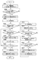
以上の構成を有する画像読取装置100の動作を、図5に示すフローチャートを用いて説明する。第一の実施形態では、読取処理を開始した後に、画像データをバッファメモリ407に取り込めるだけの空き容量がなくなった場合に、原稿の移動と、画像読取動作とを一旦中断する間欠読取モードに移行し、消費電力を低減させる処理を説明する。
The operation of the
尚、間欠読取モードへの移行は、上述のバッファメモリ407に空き容量がなくなった場合だけでなく、ホストPCが他の処理により画像データの受信を行えない状態となった場合など、特定の条件によって行われる。
Note that the transition to the intermittent reading mode is not limited to when the
まず、S501において、接続されたホストPC等からスキャン開始が指示されると、読取動作制御部404が各部及び回路へ駆動信号を出力する。具体的には、駆動クロック及びライン先頭信号をCIS401に出力し、駆動信号を増幅回路402に出力し、サンプルタイミング信号及び駆動クロックをA/D変換部403に出力する。これに対して、CIS401は、読取動作制御部404からのライン先頭信号に合わせて電荷を蓄積し、駆動クロックに合わせて蓄積された電荷を出力する。この光電変換素子に対する読取動作を所定回数繰り返すことにより、動作停止時にCIS401に蓄積された電荷を放電させ(リセットし)、正常動作状態に回復する。
First, in S501, when a scan start is instructed from the connected host PC or the like, the reading
次に、S502において、読取動作制御部404はCIS401が正常動作状態になったか否かをCIS401から出力されるアナログ信号に基づいて判断する。通常、CIS401は読み取り動作停止中に外光などの影響から電荷の蓄積量が飽和した状態になってしまう。この場合、光源204、205を点灯させない状態でCIS401を駆動させることで、この溜まってしまった電荷が抜けていき、最終的にCIS401から出力されるアナログ信号が暗状態での出力値になる。この出力値の変化(所定値になったか)を読取動作制御部404がA/D変換部403から出力されるデジタルデータを監視することにより判断する。
In step S <b> 502, the reading
次に、S503において、回復動作が完了後、読取動作制御部404は光源点灯信号を光源点灯部405に出力し、S504において、駆動開始を指示する駆動制御信号を駆動制御部406に出力する。この指示により、駆動制御部406が送りモータ3を駆動し、原稿を搬送(移動)させる。尚、光源点灯信号はS503ではなく、後述する原稿が読取開始位置に到達してから供給するように構成してもかまわない。
In step S503, after the recovery operation is completed, the reading
次に、S505において、読取動作制御部404は、原稿が読取開始位置に到達したか否かを判定し、到達するとS506へ処理を進め、バッファメモリ407に画像データを取り込めるだけの空き容量があるか否かを確認する。ここで、読取動作制御部404は、バッファメモリ407に空き容量が十分あった場合にはS507へ処理を進め、1ラインずつ画像データをバッファメモリ407に取り込む。
In step S <b> 505, the reading
次に、S508において、読取動作制御部404は、この画像データの取り込み処理と並行してホストPCへの転送処理を開始する。具体的には、ホストPCへ転送する分だけバッファメモリ407に画像データが蓄積されると、蓄積された画像データを外部I/F部408を介してホストPCへ転送する。尚、この転送処理は画像データの取り込み処理とは非同期に行われるものとする。
In step S <b> 508, the reading
次に、S509において、読取動作制御部404は、原稿1ページ分終了したか否かを判定し、終了であればS510へ処理を進め、送りモータ3の停止を指示する駆動制御信号を駆動制御部406に出力する。そして、S511において、読取動作制御部404は、各部及び回路に対する駆動信号の出力を停止する。
Next, in step S509, the reading
一方、S506において、読取動作制御部404は、バッファメモリ407に空き容量がないと判断された場合はS512へ処理を進める。このS512では、読取動作制御部404は画像データを取り込めないので、送りモータ3の停止を指示する駆動制御信号を駆動制御部406に出力し、読み取り動作を一旦中断する。そして、S513において、読取動作制御部404はCIS401、増幅回路402、A/D変換部403、光源点灯部405に供給している駆動信号を全て停止する。
On the other hand, if it is determined in S506 that the
このように制御することにより、読取動作停止中は、CIS401、増幅回路402、A/D変換部403、光源点灯部405が動作せず、無駄な電力消費を抑えることが可能となる。
By controlling in this way, the
更に、上述のS506でバッファメモリ407の空き容量が1ライン分以上残っている場合に空き容量ありと判定することにより、読取動作を一旦中断する直前の画像データも取り込むことが可能となる。また、読取動作制御部404が読取動作を一旦中断する前に、前回のライン先頭信号から1走査時間以上経過後に、ライン先頭信号をCIS401に入力する。これにより、そのときまでに蓄積された電荷をCIS401から取り出すことができ、異常なデータが出力されることやデータの欠落を防ぐことが可能となる。
Furthermore, when the free space of the
次に、S514において、ホストPCへの転送処理によりバッファメモリ407に十分な空きができるまで待ち、空きができるとS515へ処理を進め、読取動作制御部404は間欠読取モードから復帰して読取動作を再開する。具体的には、S515〜S518まで上述のS501〜S504と同様に処理を行う。これにより、読取動作停止中に、CIS401に溜まってしまった電荷を抜き、この電荷が抜けたことを読取動作制御部404が判定でき、CIS401を正常な状態から動作させることが可能となる。
Next, in S514, the process waits until the
第一の実施形態によれば、間欠読取モードへ移行し、スキャン動作を停止するとともに、各デバイスへの制御信号を停止し、各デバイスの動作を停止することにより、待ち時間の使用電力を低減させることが可能となる。 According to the first embodiment, the operation is shifted to the intermittent reading mode, the scanning operation is stopped, the control signal to each device is stopped, and the operation of each device is stopped, thereby reducing the power consumption during the waiting time. It becomes possible to make it.
[第二の実施形態]
次に、図面を参照しながら本発明に係る第二の実施形態を詳細に説明する。第二の実施形態では、図4に示す第一の実施形態における画像読取装置の構成に、更に電源制御部を追加し、間欠読取モードへ移行した際に、各部及び回路へ供給する電源を制御するものである。
[Second Embodiment]
Next, a second embodiment according to the present invention will be described in detail with reference to the drawings. In the second embodiment, a power supply control unit is further added to the configuration of the image reading apparatus in the first embodiment shown in FIG. 4, and the power supplied to each unit and circuit is controlled when shifting to the intermittent reading mode. To do.
第二の実施形態における画像読取装置の構成の概略を、図4に示すブロック図を用いて説明する。尚、図4に示す第一の実施形態と同様な機能を有する各部及び回路には同一の符号を付し、説明は省略する。 An outline of the configuration of the image reading apparatus according to the second embodiment will be described with reference to a block diagram shown in FIG. In addition, the same code | symbol is attached | subjected to each part and circuit which have the function similar to 1st embodiment shown in FIG. 4, and description is abbreviate | omitted.
図6に示すように、第二の実施形態では、読取動作制御部404に電源制御部601が接続され、読取動作制御部404がバッファメモリ407に空き容量がないと判断すると、電源制御部601を制御して消費電力を削減する。つまり、電源制御部601は、読取動作制御部404の指示により、CIS401、増幅回路402、A/D変換部403、光源点灯部405に供給する電源のオン/オフを行う。
As shown in FIG. 6, in the second embodiment, when the
ここで、第二の実施形態における画像読取装置の動作を、図7に示すフローチャートを用いて説明する。尚、図7に示すS701〜S713、S717〜S720における処理は、第一の実施形態で説明した図5に示すS501〜S513、S515〜S518での処理と同じであり、説明は省略する。 Here, the operation of the image reading apparatus in the second embodiment will be described with reference to the flowchart shown in FIG. Note that the processing in S701 to S713 and S717 to S720 shown in FIG. 7 is the same as the processing in S501 to S513 and S515 to S518 shown in FIG. 5 described in the first embodiment, and the description thereof will be omitted.
S706において、読取動作制御部404が、バッファメモリ407に空き容量がないと判断すると間欠読取モードへ移行し、第一の実施形態と同様に、送りモータ3の停止を指示し(S712)、駆動信号を全て停止する(S713)。
In S706, when the reading
次に、S714において、読取動作制御部404は、電源制御部601に対してCIS401、増幅回路402、A/D変換部403、光源点灯部405に供給する電源をオフするように指示する。この指示により、電源制御部601は指示された各部及び回路への電源供給をオフする。従って、読取動作停止中はCIS401、増幅回路402、A/D変換部403、光源点灯部405への電源がオフされているので、無駄な電力を削減することができる。
In step S <b> 714, the reading
第二の実施形態では、例えばホストPCが他の処理により画像データの受信を行えない状態が長く続くような場合にも、電源をオフしているので、第一の実施形態に比べて更に電力を削減する効果が得られる。 In the second embodiment, for example, even when the host PC cannot receive image data by other processing for a long time, the power is turned off. The effect of reducing is obtained.
次に、S715において、ホストPCへの転送処理によりバッファメモリ407に十分な空きができるまで待ち、空きができるとS716へ処理を進め、読取動作制御部404は電源制御部601に対して電源をオンするように指示する。この指示により、電源制御部601はCIS401、増幅回路402、A/D変換部403、光源点灯部405への電源供給を再開する。これ以降の処理(S717以降)は、第一の実施形態と同様であり、説明は省略する。
Next, in step S715, the process waits until the
第二の実施形態によれば、間欠読取モードへ移行し、各部及び回路への電源をオフすることにより、読取動作中の無駄な電力を削減することが可能となる。また、読取動作停止中に画像データの転送処理に長い時間がかかっても、その間は電源がオフされているので、更に電力を削減する効果が得られる。 According to the second embodiment, it is possible to reduce unnecessary power during the reading operation by shifting to the intermittent reading mode and turning off the power to each unit and circuit. Even if it takes a long time to transfer the image data while the reading operation is stopped, the power is turned off during that time, so that the effect of further reducing the power can be obtained.
[第三の実施形態]
次に、図面を参照しながら本発明に係る第三の実施形態を詳細に説明する。第一の実施形態では、A/D変換部403の出力によりCIS401の状態を検知していたが、第三の実施形態では図4に示す第一の実施形態における画像読取装置の構成に、更にアナログ信号監視部を備え、直接検知するものである。これにより、増幅回路402、A/D変換部403を駆動することなく、CIS401の状態を検知でき、第一の実施形態に比べて更に消費電力を削減することができる。
[Third embodiment]
Next, a third embodiment according to the present invention will be described in detail with reference to the drawings. In the first embodiment, the state of the
第三の実施形態における画像読取装置の構成の概略を、図8に示すブロック図を用いて説明する。尚、図4に示す第一の実施形態と同様な機能を有する各部及び回路には同一の符号を付し、説明は省略する。 An outline of the configuration of the image reading apparatus according to the third embodiment will be described with reference to a block diagram shown in FIG. In addition, the same code | symbol is attached | subjected to each part and circuit which have the function similar to 1st embodiment shown in FIG. 4, and description is abbreviate | omitted.
図8に示すように、第三の実施形態では、CIS401が出力するアナログ信号を監視するアナログ信号監視部801を更に備え、読取動作制御部404が直接CIS401の状態を検知できるように構成されている。ここで、アナログ信号監視部801は、CIS401から出力されるアナログ信号を監視し、アナログ信号のレベルが所定値に収まったことを検知すると、その状態を読取動作制御部404へ通知する。尚、アナログ信号監視部801は、例えばコンパレータ等で構成されてもよい。
As shown in FIG. 8, the third embodiment further includes an analog
また、アナログ信号監視部801は、CIS401から出力されるアナログ信号を監視しているが、増幅回路402により増幅されたアナログ信号を監視するように構成されてもよい。
The analog
ここで、第三の実施形態における画像読取装置の動作を、図9に示すフローチャートを用いて説明する。まず、S901において、接続されたホストPC等からスキャン開始が指示されると、読取動作制御部404はCIS401だけに駆動信号を出力する。次に、S902において、読取動作制御部404はCIS401が正常動作状態になったか否かを、アナログ信号監視部801が出力するアナログ信号に応じて判断する。ここで、読取動作制御部404は、出力されたアナログ信号が所定値になったと判断するとS903へ処理を進め、CIS401以外の各部及び回路へ駆動信号を出力する。
Here, the operation of the image reading apparatus according to the third embodiment will be described with reference to the flowchart shown in FIG. First, in S <b> 901, when a scan start is instructed from the connected host PC or the like, the reading
尚、S915及びS917での処理をS901及びS903での処理と同じにする点を除き、S904以降の処理は第一の実施形態で説明した図1に示すS504以降の処理と同じである。 Note that the processing after S904 is the same as the processing after S504 shown in FIG. 1 described in the first embodiment, except that the processing at S915 and S917 is the same as the processing at S901 and S903.
第三の実施形態によれば、増幅回路402、A/D変換部403を駆動することなく、CIS401の状態を検知でき、第一の実施形態に比べて更に消費電力を削減することができる。
According to the third embodiment, the state of the
[第四の実施形態]
次に、図面を参照しながら本発明に係る第四の実施形態を詳細に説明する。第四の実施形態では、図10に示すように、図4に示す第一の実施形態における画像読取装置の構成に、第二の実施形態の電源制御部601を追加し、第三の実施形態のアナログ信号監視部801を備えたものである。
[Fourth embodiment]
Next, a fourth embodiment according to the present invention will be described in detail with reference to the drawings. In the fourth embodiment, as shown in FIG. 10, the
ここで、第四の実施形態における画像読取装置の動作を、図11に示すフローチャートを用いて説明する。まず、S1101において、接続されたホストPC等からスキャン開始が指示されると、読取動作制御部404は第三の実施形態と同様に、CIS401だけに駆動信号を出力する。次に、S1102〜S1113において、第三の実施形態で説明した図9に示すS902〜S913と同じ処理を行う。
Here, the operation of the image reading apparatus according to the fourth embodiment will be described with reference to the flowchart shown in FIG. First, in S1101, when the start of scanning is instructed from the connected host PC or the like, the reading
次に、S1114において、読取動作制御部404は、第二の実施形態で説明した図7に示すS714と同じ処理、即ち電源制御部601に対して各部及び回路に供給する電源をオフするように指示する。この指示により、電源制御部601はCIS401、増幅回路402、A/D変換部403、光源点灯部405への電源供給をオフする。
Next, in S1114, the reading
次に、S1115において、第二の実施形態と同様に、ホストPCへの転送処理によりバッファメモリ407に十分な空きができるまで待ち、空きができるとS1116へ処理を進める。このS1116は、第三の実施形態で説明した図9に示すS915と同じ処理、即ちCIS401だけに駆動信号を出力する。これ以降の処理(S1117以降)は、第三の実施形態と同様であり、説明は省略する。
Next, in S1115, as in the second embodiment, the process waits until there is sufficient space in the
第四の実施形態によれば、第一の実施形態における効果に加えて、第二及び第三の実施形態における効果を得ることができる。 According to the fourth embodiment, in addition to the effects in the first embodiment, the effects in the second and third embodiments can be obtained.
[第五の実施形態]
次に、図面を参照しながら本発明に係る第五の実施形態を詳細に説明する。第五の実施形態では、図4に示す第一の実施形態における画像読取装置の構成に、外部電源から供給される電力を蓄電する蓄積素子を加えたものである。
[Fifth embodiment]
Next, a fifth embodiment according to the present invention will be described in detail with reference to the drawings. In the fifth embodiment, a storage element for storing electric power supplied from an external power source is added to the configuration of the image reading apparatus in the first embodiment shown in FIG.
第五の実施形態における画像読取装置の構成の概略を、図12に示すブロック図を用いて説明する。尚、図4に示す第一の実施形態と同様な機能を有する各部及び回路には同一の符号を付し、説明は省略する。 An outline of the configuration of the image reading apparatus according to the fifth embodiment will be described with reference to a block diagram shown in FIG. In addition, the same code | symbol is attached | subjected to each part and circuit which have the function similar to 1st embodiment shown in FIG. 4, and description is abbreviate | omitted.
図12において、外部電源入力部1201は、外部電源から供給される交流電圧を直流に変換し、電流制御部1202に送る。尚、外部電源入力部1201はACアダプタなどの画像読取装置の外部にあっても構わない。また、ホストPCからユニバーサルシリアルバス(USB)などによって供給される電源であっても構わない。
In FIG. 12, the external power
ここで、外部電源入力部1201は不図示の外部入力用端子を備え、画像読取装置内のCIS401、増幅回路402、A/D変換部403、光源点灯部405や不図示の負荷へ電力を供給する。また、蓄電素子1203から各負荷へ電力伝送される経路は直接接続され、蓄電素子1203の充電電圧値がそのまま負荷へ供給される。
The external
また、蓄電素子1203には、例えば充放電耐久性の高い電気二重層キャパシタなどが設けられている。尚、蓄電素子1203は外部電源入力部1201から供給された電力を一時的に蓄えることが可能である。
In addition, the
電流制御部1202は、ある一定の電流が蓄電素子1203へ流れるように制御可能である。そして、電圧検知部1204は、蓄電素子1203の電圧を監視することにより、蓄電素子1203に蓄電された電力を測定する。
The
ここで、第五の実施形態における画像読取装置の動作を、図13に示すフローチャートを用いて説明する。尚、図13に示すS1301〜S1313、S1317〜S1320における処理は、第一の実施形態で説明した図5に示すS501〜S513、S515〜S518での処理と同じであり、説明は省略する。 Here, the operation of the image reading apparatus according to the fifth embodiment will be described with reference to the flowchart shown in FIG. Note that the processing in S1301 to S1313 and S1317 to S1320 shown in FIG. 13 is the same as the processing in S501 to S513 and S515 to S518 shown in FIG. 5 described in the first embodiment, and a description thereof will be omitted.
S1306において、読取動作制御部404がバッファメモリ407に空き容量がないと判断すると間欠読取モードへ移行し、第一の実施形態と同様に、送りモータ3の停止を指示し(S1312)、駆動信号を全て停止する(S1313)。これにより、読取動作停止中はCIS401、増幅回路402、A/D変換部403、光源点灯部405が動作せず、電力消費量が抑えられるため、蓄電素子1203に接続された負荷が減少することになる。
In S1306, when the reading
そこで、S1314において、電流制御部1202が、上述の動作停止により減った分、蓄電素子1203に電力を充電させるように電流を制御し、充電を開始する。そして、S1315において、バッファメモリ407に空き容量ができるまで充電を続行し、空き容量ができるとS1316へ処理を進め、蓄電素子1203に充電する制御を終了する。尚、蓄電素子1203がある一定の電圧になったと電圧検知部1204が検知した場合、充電を完了するように構成しても構わない。
Therefore, in S1314, the
第五の実施形態によれば、読取動作が停止して、負荷が軽くなると蓄電素子1203に充電を行うように制御することにより、供給能力の低い外部電源入力部を使用することが可能となる。
According to the fifth embodiment, when the reading operation is stopped and the load is lightened, it is possible to use the external power input unit having a low supply capability by controlling the
また、読取動作を停止する条件は、バッファメモリ407の空き容量がなくなったときだけではなく、蓄電素子1203の電圧が低くなったときとしても構わない。これにより、蓄電素子1203の残り電力が少なくなると、読取動作を停止し、蓄電素子1203を充電することが可能となる。
The reading operation may be stopped not only when the
更に、第三の実施形態のように、アナログ信号監視部801を設け、読取動作再開時にCIS401が正常動作状態になったか否かをアナログ信号監視部801が監視するようにしても構わない。
Further, as in the third embodiment, an analog
[第六の実施形態]
次に、図面を参照しながら本発明に係る第六の実施形態を詳細に説明する。第六の実施形態は、図14に示すように、図12に示す第五の実施形態における画像読取装置の構成に、第二の実施形態の電源制御部601を追加したものである。
[Sixth embodiment]
Next, a sixth embodiment according to the present invention will be described in detail with reference to the drawings. In the sixth embodiment, as shown in FIG. 14, the
ここで、第六の実施形態における画像読取装置の動作を、図15に示すフローチャートを用いて説明する。尚、図15に示すS1501〜S1513、S1515〜S1517、S1519〜S1522における処理は、第五の実施形態の説明した図13に示すS1301〜S1313、S1314〜S1316、S1317〜S1320での処理と同じである。 Here, the operation of the image reading apparatus according to the sixth embodiment will be described with reference to the flowchart shown in FIG. The processes in S1501 to S1513, S1515 to S1517, and S1519 to S1522 shown in FIG. 15 are the same as the processes in S1301 to S1313, S1314 to S1316, and S1317 to S1320 shown in FIG. 13 described in the fifth embodiment. is there.
S1506において、読取動作制御部404がバッファメモリ407に空き容量がないと判断すると間欠読取モードへ移行し、送りモータ3の停止(S1512)、駆動信号の停止(S1313)を行う。次に、S1514において、第二の実施形態と同様に、読取動作制御部404は、電源制御部601に対してCIS401、増幅回路402、A/D変換部403、光源点灯部405に供給する電源をオフするように指示する。
In S1506, when the reading
この指示により、電源制御部601は指示された各部及び回路への電源供給をオフする。従って、読取動作停止中はCIS401、増幅回路402、A/D変換部403、光源点灯部405への電源がオフされているので、電力消費量が抑えられ、蓄電素子1203に接続された負荷が減ることになる。
In response to this instruction, the
そこで、S1515において、第五の実施形態と同様に、電流制御部1202が、上述の動作停止により減った分、蓄電素子1203に電力を充電させるように電流を制御し、充電を開始する。そして、S1516において、バッファメモリ407に空き容量ができるまで充電を続行し、空き容量ができるとS1517へ処理を進め、蓄電素子1203に充電する制御を終了する。尚、蓄電素子1203がある一定の電圧になったと電圧検知部1204が検知した場合、充電を完了するように構成しても構わない。
Therefore, in S1515, as in the fifth embodiment, the
次に、S1518において、読取動作制御部404は電源制御部601に対して電源をオンするように指示する。この指示により、電源制御部601はCIS401、増幅回路402、A/D変換部403、光源点灯部405への電源供給を再開する。
In step S <b> 1518, the reading
第六の実施形態によれば、上述の第五の実施形態における効果に加えて第二の実施形態における効果も得ることができる。 According to the sixth embodiment, in addition to the effect in the fifth embodiment described above, the effect in the second embodiment can also be obtained.
更に、第四の実施形態のように、アナログ信号監視部801を設け、読取動作再開時にCIS401が正常動作状態になったか否かをアナログ信号監視部801が監視するようにしても構わない。
Further, as in the fourth embodiment, an analog
[他の実施形態]
また、本発明は、以下の処理を実行することによっても実現される。即ち、上述した実施形態の機能を実現するソフトウェア(プログラム)を、ネットワーク又は各種記憶媒体を介してシステム或いは装置に供給し、そのシステム或いは装置のコンピュータ(またはCPUやMPU等)がプログラムを読み出して実行する処理である。
[Other Embodiments]
The present invention can also be realized by executing the following processing. That is, software (program) that realizes the functions of the above-described embodiments is supplied to a system or apparatus via a network or various storage media, and a computer (or CPU, MPU, or the like) of the system or apparatus reads the program. It is a process to be executed.
Claims (7)
前記原稿の画像を読み取る読取動作を一旦中断する間欠読取モードを有し、
前記光電変換により変換されたアナログ信号を監視する監視手段と、
前記読取動作を行っている際に、特定の条件により前記間欠読取モードに移行する場合、前記原稿を移動させる駆動系への信号、前記光電変換により画像を読み取る読取系への信号及び前記光源を点灯させる信号の供給を停止する停止手段と、
前記間欠読取モードから復帰する際に、前記停止手段により前記駆動系への信号の供給を停止した状態で、前記読取系への信号を供給し、前記アナログ信号が所定値以下になったことを前記監視手段によって検知すると、前記光源を点灯させる信号及び前記駆動系への信号を供給して前記読取動作を再開する再開手段と、
を有することを特徴とする画像読取装置。 An image reading device that irradiates a document with light from a light source, photoelectrically converts reflected light from the document, and reads an image of the document,
Having an intermittent reading mode for temporarily interrupting a reading operation of reading the image of the original;
Monitoring means for monitoring the analog signal converted by the photoelectric conversion;
When shifting to the intermittent reading mode under specific conditions during the reading operation, the signal to the drive system for moving the document, the signal to the reading system for reading an image by the photoelectric conversion, and the light source Stop means for stopping the supply of the signal to be lit,
When returning from the intermittent reading mode, the supply of signals to the drive system in a stopped state by the stop means, a signal to the reading system subjected sheet, said analog signal is equal to or less than a predetermined value Is detected by the monitoring means, resuming means for supplying a signal for turning on the light source and a signal to the drive system to resume the reading operation;
An image reading apparatus comprising:
前記電源制御手段は、前記間欠読取モードに移行する際に前記読取系及び前記光源への電源供給を停止し、前記間欠読取モードから復帰する際には前記読取系及び前記光源への電源供給を再開することを特徴とする請求項1に記載の画像読取装置。 A power control means for controlling power supply to the reading system and the light source;
The power control means stops supplying power to the reading system and the light source when shifting to the intermittent reading mode, and supplies power to the reading system and the light source when returning from the intermittent reading mode. The image reading apparatus according to claim 1, wherein the image reading apparatus restarts.
前記間欠読取モードに移行した際に、前記蓄電素子に電力を充電させるように制御する制御手段と、
を更に有することを特徴とする請求項1乃至3の何れか1項に記載の画像読取装置。 A storage element that performs charging / discharging with power from an external power source and supplies power to the reading system and the light source;
Control means for controlling the power storage element to charge power when the intermittent reading mode is entered;
The image reading apparatus according to claim 1, further comprising:
前記原稿の画像を読み取る読取動作を一旦中断する間欠読取モードを有し、
前記光電変換により変換されたアナログ信号を監視する監視工程と、
停止手段が、前記読取動作を行っている際に、特定の条件により前記間欠読取モードに移行する場合、前記原稿を移動させる駆動系への信号、前記光電変換により画像を読み取る読取系への信号及び前記光源を点灯させる信号の供給を停止する停止工程と、
再開手段が、前記間欠読取モードから復帰する際に、前記停止工程により前記駆動系への信号の供給を停止した状態で、前記読取系への信号を供給し、前記アナログ信号が所定値以下になったことを前記監視工程によって検知すると、前記光源を点灯させる信号及び前記駆動系への信号を供給して前記読取動作を再開する再開工程と、
を有することを特徴とする画像読取装置の制御方法。 A method for controlling an image reading apparatus that irradiates a document with light from a light source, photoelectrically converts reflected light from the document, and reads an image of the document.
Having an intermittent reading mode for temporarily interrupting a reading operation of reading the image of the original;
A monitoring step of monitoring an analog signal converted by the photoelectric conversion;
When the stopping unit is performing the reading operation and the mode is shifted to the intermittent reading mode due to a specific condition, a signal to the driving system for moving the document and a signal to the reading system for reading an image by the photoelectric conversion And a stopping step of stopping supply of a signal for turning on the light source,
Resuming means, when returning from the intermittent reading mode, the state in which the supply and stop of the signal to the drive system by stopping step, a signal to the reading system subjected sheet, the analog signal is below a predetermined value When it is detected by the monitoring step, a restarting step of restarting the reading operation by supplying a signal for turning on the light source and a signal to the drive system,
An image reading apparatus control method comprising:
Priority Applications (1)
| Application Number | Priority Date | Filing Date | Title |
|---|---|---|---|
| JP2012212906A JP6147978B2 (en) | 2012-09-26 | 2012-09-26 | Image reading apparatus and control method thereof |
Applications Claiming Priority (1)
| Application Number | Priority Date | Filing Date | Title |
|---|---|---|---|
| JP2012212906A JP6147978B2 (en) | 2012-09-26 | 2012-09-26 | Image reading apparatus and control method thereof |
Publications (3)
| Publication Number | Publication Date |
|---|---|
| JP2014068242A JP2014068242A (en) | 2014-04-17 |
| JP2014068242A5 JP2014068242A5 (en) | 2015-12-03 |
| JP6147978B2 true JP6147978B2 (en) | 2017-06-14 |
Family
ID=50744227
Family Applications (1)
| Application Number | Title | Priority Date | Filing Date |
|---|---|---|---|
| JP2012212906A Active JP6147978B2 (en) | 2012-09-26 | 2012-09-26 | Image reading apparatus and control method thereof |
Country Status (1)
| Country | Link |
|---|---|
| JP (1) | JP6147978B2 (en) |
Families Citing this family (1)
| Publication number | Priority date | Publication date | Assignee | Title |
|---|---|---|---|---|
| JP7182941B2 (en) * | 2018-08-01 | 2022-12-05 | キヤノン株式会社 | IMAGE INPUT DEVICE, CONTROL METHOD AND PROGRAM FOR IMAGE INPUT DEVICE |
Family Cites Families (2)
| Publication number | Priority date | Publication date | Assignee | Title |
|---|---|---|---|---|
| JP5258403B2 (en) * | 2008-06-11 | 2013-08-07 | キヤノン株式会社 | Charge control device and control method thereof |
| JP5313723B2 (en) * | 2009-02-27 | 2013-10-09 | キヤノン電子株式会社 | Image reading device |
-
2012
- 2012-09-26 JP JP2012212906A patent/JP6147978B2/en active Active
Also Published As
| Publication number | Publication date |
|---|---|
| JP2014068242A (en) | 2014-04-17 |
Similar Documents
| Publication | Publication Date | Title |
|---|---|---|
| JP2013236167A (en) | Image formation device | |
| JP2006326861A (en) | Image forming apparatus | |
| US20090039594A1 (en) | Image forming apparatus | |
| JP6147978B2 (en) | Image reading apparatus and control method thereof | |
| JPH05328059A (en) | Image reader | |
| KR101624383B1 (en) | Image forming apparatus | |
| US9167123B2 (en) | Image reader apparatus and method of driving the same | |
| US11611672B2 (en) | Technique for cooperation between plurality of separate controllers provided in image forming apparatus | |
| JP5313723B2 (en) | Image reading device | |
| JP2005278348A (en) | Regenerated energy utilizing device of dc motor | |
| US20160057306A1 (en) | Apparatus, method, and storage medium | |
| JP5680942B2 (en) | Sheet feeding apparatus and image forming apparatus | |
| JP6265739B2 (en) | Conveying device and motor temperature prediction method | |
| JP2008107523A (en) | Image forming apparatus | |
| JP2017212703A (en) | Image reading device | |
| JP5522391B2 (en) | Image forming apparatus and drive motor control method | |
| JP6021480B2 (en) | Printing device | |
| JP2020105014A (en) | Medium transport device, controlling method, and controlling program | |
| JP2007243441A (en) | Image reader, its control method and program | |
| JP2011015297A (en) | Image reading apparatus and control method therefor, and sheet processing apparatus | |
| JP2010173778A (en) | Paper feeder and image forming device | |
| JP5919206B2 (en) | Image forming apparatus | |
| JP2024065450A (en) | Image reader | |
| JP2015061150A (en) | Scanner | |
| WO2019209413A2 (en) | Controlling paper interval for scanning image |
Legal Events
| Date | Code | Title | Description |
|---|---|---|---|
| A621 | Written request for application examination |
Free format text: JAPANESE INTERMEDIATE CODE: A621 Effective date: 20150925 |
|
| A521 | Request for written amendment filed |
Free format text: JAPANESE INTERMEDIATE CODE: A523 Effective date: 20151019 |
|
| A977 | Report on retrieval |
Free format text: JAPANESE INTERMEDIATE CODE: A971007 Effective date: 20160907 |
|
| A131 | Notification of reasons for refusal |
Free format text: JAPANESE INTERMEDIATE CODE: A131 Effective date: 20160930 |
|
| A521 | Request for written amendment filed |
Free format text: JAPANESE INTERMEDIATE CODE: A523 Effective date: 20161124 |
|
| A131 | Notification of reasons for refusal |
Free format text: JAPANESE INTERMEDIATE CODE: A131 Effective date: 20170324 |
|
| A521 | Request for written amendment filed |
Free format text: JAPANESE INTERMEDIATE CODE: A523 Effective date: 20170411 |
|
| TRDD | Decision of grant or rejection written | ||
| A01 | Written decision to grant a patent or to grant a registration (utility model) |
Free format text: JAPANESE INTERMEDIATE CODE: A01 Effective date: 20170424 |
|
| A61 | First payment of annual fees (during grant procedure) |
Free format text: JAPANESE INTERMEDIATE CODE: A61 Effective date: 20170518 |
|
| R150 | Certificate of patent or registration of utility model |
Ref document number: 6147978 Country of ref document: JP Free format text: JAPANESE INTERMEDIATE CODE: R150 |
|
| R250 | Receipt of annual fees |
Free format text: JAPANESE INTERMEDIATE CODE: R250 |
|
| R250 | Receipt of annual fees |
Free format text: JAPANESE INTERMEDIATE CODE: R250 |
|
| R250 | Receipt of annual fees |
Free format text: JAPANESE INTERMEDIATE CODE: R250 |
|
| R250 | Receipt of annual fees |
Free format text: JAPANESE INTERMEDIATE CODE: R250 |