JP6147344B2 - Needle guard - Google Patents
Needle guard Download PDFInfo
- Publication number
- JP6147344B2 JP6147344B2 JP2015529928A JP2015529928A JP6147344B2 JP 6147344 B2 JP6147344 B2 JP 6147344B2 JP 2015529928 A JP2015529928 A JP 2015529928A JP 2015529928 A JP2015529928 A JP 2015529928A JP 6147344 B2 JP6147344 B2 JP 6147344B2
- Authority
- JP
- Japan
- Prior art keywords
- longitudinal member
- needle
- distal
- needle guard
- base
- Prior art date
- Legal status (The legal status is an assumption and is not a legal conclusion. Google has not performed a legal analysis and makes no representation as to the accuracy of the status listed.)
- Expired - Fee Related
Links
Images


Classifications
-
- A—HUMAN NECESSITIES
- A61—MEDICAL OR VETERINARY SCIENCE; HYGIENE
- A61M—DEVICES FOR INTRODUCING MEDIA INTO, OR ONTO, THE BODY; DEVICES FOR TRANSDUCING BODY MEDIA OR FOR TAKING MEDIA FROM THE BODY; DEVICES FOR PRODUCING OR ENDING SLEEP OR STUPOR
- A61M25/00—Catheters; Hollow probes
- A61M25/01—Introducing, guiding, advancing, emplacing or holding catheters
- A61M25/06—Body-piercing guide needles or the like
- A61M25/0612—Devices for protecting the needle; Devices to help insertion of the needle, e.g. wings or holders
- A61M25/0618—Devices for protecting the needle; Devices to help insertion of the needle, e.g. wings or holders having means for protecting only the distal tip of the needle, e.g. a needle guard
-
- A—HUMAN NECESSITIES
- A61—MEDICAL OR VETERINARY SCIENCE; HYGIENE
- A61M—DEVICES FOR INTRODUCING MEDIA INTO, OR ONTO, THE BODY; DEVICES FOR TRANSDUCING BODY MEDIA OR FOR TAKING MEDIA FROM THE BODY; DEVICES FOR PRODUCING OR ENDING SLEEP OR STUPOR
- A61M5/00—Devices for bringing media into the body in a subcutaneous, intra-vascular or intramuscular way; Accessories therefor, e.g. filling or cleaning devices, arm-rests
- A61M5/178—Syringes
- A61M5/31—Details
- A61M5/32—Needles; Details of needles pertaining to their connection with syringe or hub; Accessories for bringing the needle into, or holding the needle on, the body; Devices for protection of needles
- A61M5/3205—Apparatus for removing or disposing of used needles or syringes, e.g. containers; Means for protection against accidental injuries from used needles
- A61M5/321—Means for protection against accidental injuries by used needles
- A61M5/3243—Means for protection against accidental injuries by used needles being axially-extensible, e.g. protective sleeves coaxially slidable on the syringe barrel
- A61M5/3245—Constructional features thereof, e.g. to improve manipulation or functioning
- A61M2005/3247—Means to impede repositioning of protection sleeve from needle covering to needle uncovering position
- A61M2005/325—Means obstructing the needle passage at distal end of a needle protection sleeve
-
- A—HUMAN NECESSITIES
- A61—MEDICAL OR VETERINARY SCIENCE; HYGIENE
- A61M—DEVICES FOR INTRODUCING MEDIA INTO, OR ONTO, THE BODY; DEVICES FOR TRANSDUCING BODY MEDIA OR FOR TAKING MEDIA FROM THE BODY; DEVICES FOR PRODUCING OR ENDING SLEEP OR STUPOR
- A61M2207/00—Methods of manufacture, assembly or production
-
- A—HUMAN NECESSITIES
- A61—MEDICAL OR VETERINARY SCIENCE; HYGIENE
- A61M—DEVICES FOR INTRODUCING MEDIA INTO, OR ONTO, THE BODY; DEVICES FOR TRANSDUCING BODY MEDIA OR FOR TAKING MEDIA FROM THE BODY; DEVICES FOR PRODUCING OR ENDING SLEEP OR STUPOR
- A61M25/00—Catheters; Hollow probes
- A61M25/01—Introducing, guiding, advancing, emplacing or holding catheters
- A61M25/06—Body-piercing guide needles or the like
- A61M25/0612—Devices for protecting the needle; Devices to help insertion of the needle, e.g. wings or holders
- A61M25/0618—Devices for protecting the needle; Devices to help insertion of the needle, e.g. wings or holders having means for protecting only the distal tip of the needle, e.g. a needle guard
- A61M25/0625—Devices for protecting the needle; Devices to help insertion of the needle, e.g. wings or holders having means for protecting only the distal tip of the needle, e.g. a needle guard with a permanent connection to the needle hub, e.g. a guiding rail, a locking mechanism or a guard advancement mechanism
-
- A—HUMAN NECESSITIES
- A61—MEDICAL OR VETERINARY SCIENCE; HYGIENE
- A61M—DEVICES FOR INTRODUCING MEDIA INTO, OR ONTO, THE BODY; DEVICES FOR TRANSDUCING BODY MEDIA OR FOR TAKING MEDIA FROM THE BODY; DEVICES FOR PRODUCING OR ENDING SLEEP OR STUPOR
- A61M5/00—Devices for bringing media into the body in a subcutaneous, intra-vascular or intramuscular way; Accessories therefor, e.g. filling or cleaning devices, arm-rests
- A61M5/178—Syringes
- A61M5/31—Details
- A61M5/32—Needles; Details of needles pertaining to their connection with syringe or hub; Accessories for bringing the needle into, or holding the needle on, the body; Devices for protection of needles
- A61M5/3205—Apparatus for removing or disposing of used needles or syringes, e.g. containers; Means for protection against accidental injuries from used needles
- A61M5/321—Means for protection against accidental injuries by used needles
- A61M5/3243—Means for protection against accidental injuries by used needles being axially-extensible, e.g. protective sleeves coaxially slidable on the syringe barrel
- A61M5/3273—Means for protection against accidental injuries by used needles being axially-extensible, e.g. protective sleeves coaxially slidable on the syringe barrel freely sliding on needle shaft without connection to syringe or needle
Landscapes
- Health & Medical Sciences (AREA)
- Life Sciences & Earth Sciences (AREA)
- Biophysics (AREA)
- Pulmonology (AREA)
- Engineering & Computer Science (AREA)
- Anesthesiology (AREA)
- Biomedical Technology (AREA)
- Heart & Thoracic Surgery (AREA)
- Hematology (AREA)
- Animal Behavior & Ethology (AREA)
- General Health & Medical Sciences (AREA)
- Public Health (AREA)
- Veterinary Medicine (AREA)
- Infusion, Injection, And Reservoir Apparatuses (AREA)
- Media Introduction/Drainage Providing Device (AREA)
- Portable Nailing Machines And Staplers (AREA)
Description
[関連出願の相互参照]
本出願は、2011年2月28日に出願された米国特許出願第13/037,164号の一部継続出願である。
[Cross-reference of related applications]
This application is a continuation-in-part of US patent application Ser. No. 13 / 037,164, filed Feb. 28, 2011.
本出願に開示されている発明は、安全ニードル・ガード(safety needle guard、ニードル用安全ガード、注射針用安全ガード、針用安全器具、注射針用安全器具、注射針安全保護器具)に関する。 The invention disclosed in the present application relates to a safety needle guard ( safety needle guard, needle safety guard, injection needle safety guard, needle safety device, injection needle safety device, injection needle safety protection device ) .
多くの米国特許がいくつかの安全IV(静脈内、血管内留置)カテーテル(safety IV catheters、保護機能付きIVカテーテル、安全器具付きIVカテーテル)を説明しており、それらカテーテルにおいては、その使用後にニードルの遠位先端(distal tip)を保護する機能をある程度付与されており、それら米国特許は、McLeesの米国特許第5,135,504号、Erskineの米国特許第5,797,880号、Woehrらの米国特許第6,287,278と、Bialeckiらの米国特許第6,652,486号と、McGurkの米国特許第7,291,130と、Rhadらの米国特許第7,303,548と、Menziらの米国特許第7,731,687号と、Hardingらの米国特許第7,828,774号とを含むが、それらに限定されない。 Many US patents describe several safety IV (intravenous and intravascular) catheters ( safety IV catheters, protective IV catheters, IV catheters with safety devices ) , in those catheters after use the distal tip of the needle (distal tip) are to some extent provided with a function to protect, they patent, U.S. Patent No. 5,135,504 of McLees U.S. Patent No. 5,797,880 of Erskine, Woehr U.S. Pat. No. 6,287,278, Bialecki et al. U.S. Pat. No. 6,652,486, McGurk U.S. Pat. No. 7,291,130, Rhad et al. U.S. Pat. No. 7,303,548, US Pat. No. 7,731,687 to Menzi et al. And US Pat. No. 7,828,774 to Harding et al.
上述のいくつかの従来の安全カテーテル(safety catheter、保護機能付きIVカテーテル、安全器具付きIVカテーテル)は、1または複数の欠点を有しており、それら欠点により、医療従事者や他の者が、ニードル先端が安全装置(safety mechanism、安全機構、安全保護器具)によって覆われた後に、経皮的にまたは非経皮的な血液暴露または体液暴露(患者の血液または体液が医療従事者に付着すること)という危険に潜在的に置かれる可能性がある。多数の実用的な安全IVカテーテルについては、ニードル先端自体が、その使用後、被覆される(covered)が、そのニードル先端全体が、その使用後に、完全に収容される(contained)わけではなく、その結果、そのニードルの内腔内に残存する血液や体液が作業場に漏れ出す(leak)かまたはそれ以外の方法で放出されて(escape)医療従事者に接触する可能性がある。例えば、飛散した血液が、その飛散発生個所に近接している医療従事者の目、鼻または口の粘膜域に侵入する可能性がある。そのような暴露が発生すると、その後、報告が行われ、さらに、暴露後処理、病気の予防(prophylaxis)および継続管理(follow up)が行われ、それにより、当該施設に対しては費用負担、問題の血液が付着した医療従事者個人に対しては不安を招来する。さらに、市販されているいくつかのニードル・ガードについては、その部品が、汚染されているニードル先端をもはや保護する(protect)こともシールドする(shield)こともできない場合に、不注意な事故が発生すると、簡単に、このニードル・ガードが役に立たなくなる可能性がある。 Some of the conventional safety catheters (safety catheters, IV catheters with protective functions, IV catheters with safety devices) have one or more drawbacks, which can be used by medical personnel and others. , After the needle tip is covered by a safety mechanism, percutaneous or non-percutaneous blood or body fluid exposure (patient blood or body fluid adheres to medical personnel) Could potentially be at risk. For many practical safety IV catheters, the needle tip itself is covered after its use, but the entire needle tip is not fully contained after its use, As a result, blood or bodily fluid remaining in the lumen of the needle may leak into the workplace or otherwise escape and contact the health care worker. For example, scattered blood can enter the mucosal area of the eyes, nose, or mouth of a health care worker close to the location of the scattering. When such exposure occurs, then reports are performed, further, post-exposure treatment, disease prevention (prophylaxis) and continuity management (follow Stay up-) is performed, whereby the expense for the facility, It causes anxiety for the individual medical staff with the blood in question. In addition, for some commercially available needle guards, inadvertent accidents can occur if the part can no longer protect or shield the contaminated needle tip. When this happens, the needle guard can simply become useless.
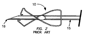
図1−図5は、安全ニードル・ガード10であって、米国特許第6,287,278号に開示されているものに類似するものを示している。このニードル・ガード10は、図1に示すように、ある材料の一部分から構成されるとともに、使用中、図2−図5に示す複数の構成態様(configurations、複数の形状)を有するように形成されている。図2および図3は、ニードル・ガード10を、それぞれ互いに異なる側面視で、かつ、ニードル15の遠位先端18が保護されない(unprotected)準備位置(ready position)にある状態で示している。図4および図5は、ニードル・ガード10を、それぞれ互いに異なる側面視で、かつ、このニードル・ガード10が遠位先端18を覆う(cover、閉塞する、保護する)ように作動させられた後の状態で示している。図4および図5に示すように、ニードル15の遠位先端18のまさに先端が保護される(protect)が、このニードルの斜部(bevel、傾斜面、開先)16内の開口内腔17が、露出したままである。このニードル・ガード10に付随する別の問題は、ニードル・ガードのアーム11および12のうちのそれぞれの遠位セグメントである遠位アーム・セグメント13および14を外向きに押し出すために、それらアーム11および12のいくつかの位置に力が加えられる可能性があるということである。これにより、遠位アーム・セグメント13および/または14が遠位先端18を保護しなくなる可能性が生じる。
1-5 show a
いくつかの実施態様によれば、IV(静脈内、血管内留置)カテーテル・アセンブリが提供され、そのIVカテーテル・アセンブリは、中空本体部を有するカテーテル・ハブであって、前記中空本体部は、近位端(proximal end)と遠位端(distal end)とを有するとともに、内部空間を画定するものと、近位端と遠位端とを有するカテーテルであって、当該カテーテルの近位端は、前記カテーテル・ハブの近位端に連結されるものと、ニードル・シャフトと遠位先端(distal tip)とを有するニードルであって、準備位置(ready position)と格納位置(retracted position、当該ニードルがニードル・ガード内に格納される位置)との間を移動可能であるとともに、前記準備位置においては、当該ニードルの遠位先端が前記カテーテルの遠位端から遠位方向に延びる一方、前記格納位置においては、当該ニードルの遠位先端が、前記カテーテルの近位端に対して近位方向に位置する位置に留置され、前記ニードル・シャフトは、プロファイルが変化するプロファイル変化部(a change in profile、形状変化部)を有するものと、アームを有するニードル・ガードとを含み、前記アームは、ベースから遠位方向に延びており、そのベースは、その内部に形成された開口部(aperture)を有し、前記ニードル・ガードは、前記ベース内に形成された前記開口部を前記ニードル・シャフトが通過する状態で、前記ニードル・シャフトにスライド可能に装着され、前記開口部は、前記ニードル・シャフトの前記プロファイル変化部に係合し、それにより、前記ニードルが前記ニードル・ガードに対して近位方向に移動する運動を制限するサイズを有し、前記アームは、弾性材を有するとともに、近位セクション、中央セクションおよび遠位セクションを有し、前記アームの遠位セクションは、前記ニードルが前記準備位置にある場合に、留置されるとともに、前記ニードル・シャフトの側部に押し付けられ、前記ニードル・ガードは、さらに、長手部材(elongate member)を含み、その長手部材は、自身の近位端と遠位端との間を延びる貫通通路(through passage)を有し、前記長手部材は、前記ベースと同じ位置または近傍位置から遠位方向に延びるとともに、前記ニードルが前記準備位置と前記格納位置との間を移動させられるにつれて前記ニードル・シャフトに沿ってスライド可能であり、前記長手部材は、長さを有し、その長さは、前記プロファイル変化部が前記ベース内の前記開口部に実質的に係合する場合に、前記ニードルの遠位先端の全体が前記長手部材の前記貫通通路内に留置されるように配置されるとともに、前記アームの遠位セクションが前記ニードル・シャフトから離脱して半径方向内向きに移動し、それにより、前記長手部材の遠位端を少なくとも部分的に覆う(cover、閉塞する、保護する)ことを実現するものとなっており、前記長手部材は、前記アームが前記長手部材の遠位端を少なくとも部分的に覆う場合に、前記ニードルが前記ニードル・ガードに対して軸方向に移動することを制限する(restrict、移動限度を規定する)のに十分な剛性を有するIVカテーテル・アセンブリである。 According to some embodiments, an IV (Intravenous, Intravascular) catheter assembly is provided, the IV catheter assembly having a hollow body portion, the hollow body portion comprising: A catheter having a proximal end and a distal end and defining an interior space, and a proximal end and a distal end, wherein the proximal end of the catheter is A needle connected to the proximal end of the catheter hub and having a needle shaft and a distal tip, the ready position and the retracted position; At a position where the needle is stored in the needle guard), and in the preparation position, the distal tip of the needle extends distally from the distal end of the catheter. On the other hand, in the retracted position, the distal tip of the needle is placed in a position located in the proximal direction with respect to the proximal end of the catheter, and the needle shaft has a profile changing portion where the profile changes. (A change in profile) and a needle guard having an arm, the arm extending in a distal direction from the base, the base having an opening formed therein The needle guard is slidably mounted on the needle shaft in a state where the needle shaft passes through the opening formed in the base, and the opening is Engaging the profile change of the needle shaft, thereby moving the needle proximally relative to the needle guard Having a size that limits movement, the arm having an elastic material and having a proximal section, a central section and a distal section, the distal section of the arm having the needle in the ready position And is pressed against the side of the needle shaft, the needle guard further including an elongated member, the longitudinal member having its proximal and distal ends The longitudinal member extends distally from the same or near position as the base and the needle moves between the ready position and the retracted position. Is slidable along the needle shaft as it is moved, and the longitudinal member has a length that is determined by the profile changing portion. The entire distal tip of the needle is disposed within the longitudinal passage of the longitudinal member when substantially engaged with the opening in the base and distal of the arm It is realized that the section is detached from the needle shaft and moves radially inward, thereby at least partially covering ( covering, protecting ) the distal end of the longitudinal member. The longitudinal member restricts the needle from moving axially relative to the needle guard when the arm at least partially covers the distal end of the longitudinal member. IV catheter assembly with sufficient rigidity to define the limit.
他のいくつかの実施態様によれば、IV(静脈内、血管内留置)カテーテル・アセンブリが提供され、そのIVカテーテル・アセンブリは、中空本体部を有するカテーテル・ハブであって、前記中空本体部は、近位端と遠位端とを有するとともに、内部空間を画定するものと、近位端と遠位端とを有するカテーテルであって、当該カテーテルの近位端は、前記カテーテル・ハブの近位端に連結されるものと、ニードル・シャフトと遠位先端とを有するニードルであって、準備位置と格納位置との間を移動可能であるとともに、前記準備位置においては、当該ニードルの遠位先端が前記カテーテルの遠位端から遠位方向に延びる一方、前記格納位置においては、当該ニードルの遠位先端が、前記カテーテルの近位端に対して近位方向に位置する位置に留置され、前記ニードル・シャフトは、プロファイルが変化するプロファイル変化部を有するものと、第1および第2アームを有するニードル・ガードとを含み、前記第1および第2アームは、ベースから遠位方向に延びており、そのベースは、その内部に形成された開口部を有し、前記ニードル・ガードは、前記ベース内に形成された前記開口部を前記ニードル・シャフトが通過する状態で、前記ニードル・シャフトにスライド可能に装着され、前記開口部は、前記ニードル・シャフトの前記プロファイル変化部に係合し、それにより、前記ニードルが前記ニードル・ガードに対して近位方向に移動する運動を制限するサイズを有し、前記第1および第2アームの各々は、弾性材を有するとともに、近位セクション、中央セクションおよび遠位セクションを有し、前記第1および第2アームは、前記ベースのうちの互いに異なるそれぞれの位置から延びるとともに、それぞれの中間セクションに沿って互いに交差し、それにより、前記第1および第2アームのそれぞれの遠位セクションが、前記ニードルが前記準備位置にある場合に、留置されるとともに、前記ニードル・シャフトの両側にそれぞれ押し付けられ、前記ニードル・ガードは、さらに、長手部材を含み、その長手部材は、自身の近位端と遠位端との間を延びる貫通通路を有し、前記長手部材は、前記ベースと同じ位置または近傍位置から遠位方向に延びるとともに、前記ニードルが前記準備位置と前記格納位置との間を移動させられるにつれて前記ニードル・シャフトに沿ってスライド可能であり、前記長手部材は、長さを有し、その長さは、前記プロファイル変化部が前記ベース内の前記開口部に実質的に係合する場合に、前記ニードルの遠位先端の全体が前記長手部材の前記貫通通路内に留置されるように配置されるとともに、前記第1および第2アームのうちの少なくとも一方の遠位セクションが前記ニードル・シャフトから離脱して半径方向内向きに移動し、それにより、前記長手部材の遠位端を少なくとも部分的に覆う(cover、閉塞する、保護する)ことを実現するものとなっており、前記長手部材は、前記第1および第2アームのうちの少なくとも一方が前記長手部材の遠位端を少なくとも部分的に覆う場合に、前記ニードルが前記ニードル・ガードに対して軸方向に移動することを制限する(restrict、移動限度を規定する)のに十分な剛性を有するIVカテーテル・アセンブリである。 In accordance with some other embodiments, an IV (intravenous, intravascular) catheter assembly is provided, wherein the IV catheter assembly is a catheter hub having a hollow body portion, the hollow body portion. Is a catheter having a proximal end and a distal end and defining an interior space, and a proximal end and a distal end, the proximal end of the catheter being connected to the catheter hub. A needle coupled to the proximal end and having a needle shaft and a distal tip, the needle being movable between a ready position and a retracted position; A distal tip extends distally from the distal end of the catheter, while in the retracted position, the distal tip of the needle is located proximal to the proximal end of the catheter. And the needle shaft includes a profile changing portion whose profile changes, and a needle guard having first and second arms, the first and second arms being remote from the base. The base has an opening formed therein, and the needle guard is in a state in which the needle shaft passes through the opening formed in the base. A slidably mounted on the needle shaft, the opening engaging the profile changing portion of the needle shaft, thereby moving the needle proximally relative to the needle guard Each of the first and second arms has an elastic material and has a proximal section and a central section. And the first and second arms extend from different positions of the base and intersect each other along a respective intermediate section, whereby the first and second arms Each distal section of the two arms is deployed when the needle is in the ready position and is pressed against each side of the needle shaft, the needle guard further including a longitudinal member; The longitudinal member has a through passage extending between its proximal and distal ends, the longitudinal member extending distally from the same or near position as the base, and the needle Slidable along the needle shaft as it is moved between a ready position and a retracted position; The material has a length such that when the profile change portion substantially engages the opening in the base, the entire distal tip of the needle is the length of the longitudinal member. A distal section of at least one of the first and second arms is moved away from the needle shaft and moved radially inwardly, thereby being positioned in a through-passage, It is intended to at least partially cover (clog, protect) the distal end of the longitudinal member, wherein the longitudinal member has at least one of the first and second arms. Stiff enough to restrict the needle from moving axially relative to the needle guard when covering at least partially the distal end of the longitudinal member IV catheter assembly having sex.
いくつかの実施態様によれば、前記ニードル・ガードは、前記長手部材が当該ニードル・ガードの前記ベースと一体的に形成されるように単一の構造体を有する。 According to some embodiments, the needle guard has a single structure such that the elongate member is integrally formed with the base of the needle guard.
いくつかの実施態様によれば、前記ニードルは、前記格納位置において、部品または特徴部によって停止させられ、それら部品または特徴部は、前記長手部材の遠位端に組み込まれるか、または他の方法により、前記長手部材の遠位端と同じ位置または近傍位置に配置される。 According to some embodiments, the needle is stopped by a part or feature in the retracted position, the part or feature being incorporated into the distal end of the longitudinal member, or other method Thus, the longitudinal member is disposed at the same position as or near the distal end of the longitudinal member.
いくつかの実施態様によれば、前記長手部材の近位セクションは、他の部分より小径である小径部(reduced diameter portion)および/または円錐台状部(frustoconical portion)であって前記ニードル・ガード上において前記ニードルを自動的に芯出しする(self-centering)ことを支援するために利用可能であるものを有する。 According to some embodiments, the proximal section of said elongate member, said needle guard to a small diameter portion smaller in diameter than the other portion (reduced diameter portion) and / or truncated cone-shaped portion (frustoconical Portion) Above has what is available to assist in self-centering the needle.
別の実施態様によれば、ニードル用安全器具(safety needle device、注射針用安全器具)が提供され、その安全器具は、ニードル・シャフトと遠位先端とを有するニードルであって、前記ニードル・シャフトは、プロファイルが変化するプロファイル変化部を前記遠位先端の近傍位置に有するものと、準備状態(ready state)と作用状態(activated state)との間を遷移させられるニードル・ガードであって、前記準備状態においては、前記ニードルの前記遠位先端が、その遠位先端が前記ニードル・ガードによって保護されない非保護状態(unprotected state)にあるが、前記作用状態においては、前記ニードルの前記遠位先端が、その遠位先端が前記ニードル・ガードによって保護される保護状態(protected state)にあるものとを含み、前記ニードル・ガードは、ベースから遠位方向に延びるアームを含み、前記ベースは、その内部に形成された開口部を有し、前記ニードル・ガードは、前記ベース内に形成された前記開口部を前記ニードル・シャフトが通過する状態で、前記ニードル・シャフトにスライド可能に装着され、前記アームは、弾性材を有するとともに、近位セクション、中央セクションおよび遠位セクションを有し、前記ニードル・ガードは、さらに、長手部材を含み、その長手部材は、前記ベースと同じ位置または近傍位置から遠位方向に延びるとともに、前記ニードル・ガードが前記準備状態用の位置(the ready position、準備位置)と前記作用状態用の位置(the activated position、作用位置)との間を移動させられるにつれて前記ニードル・シャフトの側面に沿ってそれの長さ方向に(alongside the needle shaft)スライド可能であり、前記長手部材は、近位端と、遠位端と、それら近位端と遠位端との間を延びる貫通通路とを有し、その貫通通路のうち、前記長手部材の前記近位端と同じ位置または近傍位置に位置する第1部分は、前記ニードルが前記ニードル・ガードに対して近位方向に移動することを制限する(limit、移動限度を規定する)ために、前記ニードル・シャフトの前記プロファイル変化部に係合するサイズを有し、前記長手部材は、長さを有し、その長さは、前記プロファイル変化部が前記貫通通路の前記第1部分に係合する場合に、前記ニードルの前記遠位先端の全体が前記長手部材の前記貫通通路内に留置されるように配置されることを実現するものとなっており、前記長手部材は、近位セクションおよび遠位セクションを有し、前記長手部材の前記近位セクションは、前記ベースが前記長手部材の前記近位セクション上を(on、接触状態で)第1位置とその第1位置から遠位寄りにある第2位置との間をスライド可能である状態で、前記ベースの前記開口部内に配置され、前記長手部材の前記近位セクションは、前記ニードル・ガードが前記準備状態にある場合に前記第1位置に位置し、前記ニードル・ガードが前記作用状態にある場合に前記第2位置に位置し、前記ニードル・ガードが前記準備状態にある場合に、前記アームの前記遠位セクションは、前記長手部材の前記遠位セクション上に(on、接触状態で)、前記長手部材の前記遠位端の近傍位置に留置され、ここで、前記アームの前記遠位セクションのうちの少なくとも一部が前記長手部材の外面(outer side、外側側面)に押し付けられ、前記ニードル・ガードは、前記ベースが前記第1位置から前記第2位置に移動すると、前記ニードル・ガードが前記準備状態から前記作用状態に遷移するように構成されており、前記アームの前記遠位セクションは、前記長手部材の前記遠位セクションの前記外面(outer side、外側側面)に沿って遠位方向に前記長手部材の前記遠位端に移動し、ここで、前記アームの前記遠位セクションは、前記長手部材の前記遠位端を少なくとも部分的に覆う(cover、閉塞する、保護する)ように半径方向内向きに移動し、前記長手部材は、前記アームの前記遠位セクションが前記長手部材の前記遠位端を少なくとも部分的に覆う(cover、閉塞する、保護する)場合に、前記ニードルが前記ニードル・ガードに対して軸方向に移動することを制限する(restrict、移動限度を規定する)のに十分な剛性を有する。 According to another embodiment, a safety needle device is provided, the safety device comprising a needle having a needle shaft and a distal tip. shaft is a profile change unit profile is changed at the distal tip needle guard is caused to transition between the one having a position in the vicinity, a ready state (ready state) and the working state (activated state) of, In the ready state, the distal tip of the needle is in an unprotected state where the distal tip is not protected by the needle guard, but in the working state the distal tip of the needle A tip in a protected state in which the distal tip is protected by the needle guard; The base includes an arm extending in a distal direction from the base, the base having an opening formed therein, and the needle guard includes the opening formed in the base. Slidably mounted on the needle shaft with the shaft passing therethrough, the arm having an elastic material and having a proximal section, a central section and a distal section; the needle guard further comprising: A longitudinal member that extends distally from the same or near position as the base, and wherein the needle guard is in the ready position and the working state. The length of the needle shaft along its side as it is moved between its activated position And the longitudinal member has a proximal end, a distal end, and a through passage extending between the proximal end and the distal end, the through passage being slidable along the needle shaft A first portion located at the same position as or near the proximal end of the longitudinal member restricts the needle from moving proximally with respect to the needle guard. The length of the longitudinal member has a length, the length of the longitudinal member being defined by the profile change portion of the through-passage. When engaging with the first part, the entire distal tip of the needle is disposed so as to be placed in the through-passage of the longitudinal member. The member includes a proximal section and Having a distal section, the proximal section of the longitudinal member having a base on the proximal section of the longitudinal member (on, in contact) at a first position and distally from the first position Positioned within the opening of the base in a slidable manner between a second position, the proximal section of the elongate member is configured to move the first when the needle guard is in the ready state. When the needle guard is in the second position when the needle guard is in the working state and the needle guard is in the ready state, the distal section of the arm is the longitudinal member On the distal section of the longitudinal member (on, in contact) and in the vicinity of the distal end of the longitudinal member, wherein at least a portion of the distal section of the arm is the longitudinal The needle guard is pressed against the outer side (outer side surface) of the member, and when the base moves from the first position to the second position, the needle guard changes from the preparation state to the operation state. The distal section of the longitudinal member in a distal direction along the outer side of the distal section of the longitudinal member Wherein the distal section of the arm is moved radially inward to at least partially cover (cover, occlude, protect) the distal end of the longitudinal member; A longitudinal member is formed when the distal section of the arm at least partially covers (covers, occludes, protects) the distal end of the longitudinal member. It has sufficient rigidity to limit to move axially (the restrict, defining the movement limit) relative.
別のいくつかの実施態様においては、いくつかのニードル・ガードが提供され、当該ニードル・ガードにおいては、いくつかの付勢部材(biasing members、押付け部材)が、当該ニードル・ガードの1または複数のアームに対して作用し、それにより、それらアームを付勢して前記ニードル・シャフトまたは前記長手部材に押し付けることをアシストし、このことは、当該ニードル・ガードが前記準備状態にある場合に行われてもよい。 In some other embodiments, a number of needle guards are provided, in which a number of biasing members are one or more of the needle guards. Acting on the other arm, thereby assisting the biasing of the arms against the needle shaft or the longitudinal member, which is performed when the needle guard is in the ready state. It may be broken.
本明細書には他の多くの実施態様が開示されているとともに本発明の対象として考慮されている。さらに、注目することが重要なことは、本明細書に開示されているいくつかの発明は、安全IVカテーテルに限定されるのではなく、多様なニードル関連製品のうちのいずれにでも適用することが可能であるということであり、それらニードル関連製品は、ガイドワイヤ・イントロデューサ(guidewire introducer、ガイドワイヤ挿入具、ガイドワイヤ誘導具)、血液採取装置(blood collection device)などを含むが、それらに限定されない。 Many other embodiments are disclosed herein and are considered subject of the present invention. Furthermore, it is important to note that some inventions disclosed herein are not limited to safety IV catheters, but apply to any of a variety of needle related products. These needle-related products include guidewire introducers, blood collection devices, etc., but they include It is not limited.
図41は、別の実施形態に従うニードル・ガード・アセンブリを示している。 FIG. 41 illustrates a needle guard assembly according to another embodiment.
図47は、一実施形態に従う長手部材を示している。 FIG. 47 illustrates a longitudinal member according to one embodiment.
図48は、一実施形態に従う長手部材を示している。
図49Aは、別の実施形態に従う1つの安全静脈内(intravenous、血管内留置)カテーテル・アセンブリを示している。
図49Bは、図49Aの安全静脈内(intravenous、血管内留置)カテーテル・アセンブリを示している。
FIG. 48 illustrates a longitudinal member according to one embodiment.
FIG. 49A shows one safe intravenous catheter assembly according to another embodiment.
FIG. 49B shows the safe intravenous catheter assembly of FIG. 49A.
図50は、一実施形態に従う長手部材を示している。 FIG. 50 illustrates a longitudinal member according to one embodiment.
図52は、一実施形態に従う長手部材を示している。 FIG. 52 illustrates a longitudinal member according to one embodiment.
図53は、一実施形態に従う長手部材を示している。 FIG. 53 illustrates a longitudinal member according to one embodiment.
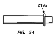
図54は、一実施形態に従う長手部材を示している。 FIG. 54 illustrates a longitudinal member according to one embodiment.
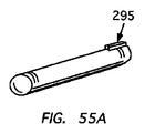
図55Aは、一実施形態に従う長手部材を示している。 FIG. 55A illustrates a longitudinal member according to one embodiment.
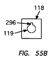
図55Bは、一実施形態に従うスプリング・クリップのベースであって、図55Aの長手部材の近位端を収容するために設けられたキー穴を有するものを示している。 FIG. 55B illustrates a spring clip base according to one embodiment having a keyhole provided to receive the proximal end of the longitudinal member of FIG. 55A.
図56Bは、一実施形態に従うスプリング・クリップのベースであって、図56Aの長手部材の近位端を収容するために設けられたキー穴を有するものを示している。 56B shows a spring clip base according to one embodiment having a keyhole provided to receive the proximal end of the longitudinal member of FIG. 56A.
図57Aおよび図57Bは、別の実施形態に従うスプリング・クリップのベースを示している。 57A and 57B show a spring clip base according to another embodiment.
図58A−図58Cは、1つの長手部材であって、それの遠位端の位置にシール部材を有するものを示している。 58A-58C illustrate one longitudinal member having a seal member at the distal end thereof.
図59は、別の実施形態に従うシール部材を示している。 FIG. 59 shows a seal member according to another embodiment.
図65は、別の実施形態に従う1つのニードル・ガードを示している。 FIG. 65 shows one needle guard according to another embodiment.
図66A−図66Cは、別の実施形態に従う1つのニードル・ガードを示している。 66A-66C show one needle guard according to another embodiment.
図68Aおよび図68Bは、別の実施形態に従う1つのニードル・ガードを示している。 68A and 68B show one needle guard according to another embodiment.
図70Aおよび図70Bは、別の実施形態に従う1つのニードル・ガードを示している。 70A and 70B show one needle guard according to another embodiment.
図6−図11は、いくつかの実施態様に従うニードル・ガード100を示している。一実施態様によれば、ニードル・ガード100の第1部分110は、図6Aまたは図6Bに示すように、弾性的特性を有する平らな材料から製造され、図7−図10に示す複数の使用中構成態様(in-use configurations)を取るための形状を有するが、ニードル・ガード100の第2部分150(図11および図12に示す)は、長手部材152を規定し、その長手部材152は、近位端(proximal end、術者に近い側の端)154と遠位端(distal end、術者から遠い側の端)156との間を延びる貫通通路153を有している。図7および図8は、ニードル・ガード100をそれぞれ互いに異なる側面図で示しており、そのニードル・ガード100は、ニードル130上の第1軸方向位置に配置されており、ここでは、ニードル130の遠位端134は、保護されない(unprotected、収納されない、露出する)状態にある。図9および図10は、ニードル・ガード100をそれぞれ互いに異なる側面図で示しており、そのニードル・ガード100は、ニードル130上の第2軸方向位置にあり、ここでは、遠位端134であって斜部(bevel、傾斜面、開先)136の全体を含むものは、保護される(protected、収納される、露出しない)状態にある。
6-11 illustrate a
一実施態様においては、ニードル・ガード100の第1部分110が、各々弾性を有する第1および第2のアーム101および102を有し、このとき、各アーム101,102は、近位端103および104と、中央セクション105および106と、遠位端107および108とを有する。ニードル・ガード100が前記第1軸方向位置にある場合に、遠位セクション107および108のそれぞれのリップ・セグメント(lip segment、折返し部)111および112がニードル・シャフト131の両側に配置されるとともに、それら両側に押し付けられるように、第1および第2アーム101および102は、ベース118の、互いに異なる複数の位置から遠位方向に延びるとともに、それらアーム101および102の中央セクション105および106に沿って互いに交差している。ニードル・ガード100の第1部分110は、ニードル・シャフト131上にスライド可能に装着され、このとき、ニードル・シャフト131は、ベース118に形成された開口部119を貫通して通過している。一実施態様においては、開口部119が、ニードル130上のプロファイル変化部132に係合するサイズを有しており、その目的は、ニードル・ガード100が前記第2軸方向位置にある場合に、ニードル130とニードル・ガード100との間での第1方向への運動を制限することにある。プロファイル変化部132は、ニードル・シャフト131上のクリンプ(crimp、ひだ部、波状部、潰し部、型押し部、圧着部、障害部)、または、図33および図35に示すような拡大部(enlargement、肥大部、膨張部、拡径部)であって任意の形式のものを有してもよい。
In one embodiment, the
図7に示すように、長手部材152は、ニードル・ガード100が前記準備位置(ready position、前記第1軸方向位置)にある場合に、その長手部材152の近位端154は、ベース118と同じ位置またはその近傍に位置する一方、その長手部材152の遠位端156は、アーム101のリップ・セグメント111と同じ位置またはその近傍に位置する状態で、ニードル・ガード100上に配置されている。いくつかの実施形態においては、長手部材152が、ニードル130と実質的に同軸であり、このとき、貫通通路153の直径または断面積(cross-section area)は、長手部材152がプロファイル変化部132を乗り越えて(over)スライドすることが可能であるのに十分な大きさを有する。別のいくつかの実施形態においては、長手部材152が、ニードル130と実質的に同軸であり、このとき、貫通通路153の全体またはそれの近位部の直径または断面積は、プロファイル変化部132の断面積より小さい。複数の実施態様においては、貫通通路153の全部または一部の断面積が、プロファイル変化部132の断面積より小さく、それらの実施態様においては、貫通通路153が、例えば図9に示すものと同様に、プロファイル変化部132上において(over、乗り越えようとするときに)拡張(expandable、拡径)可能であるように構成されている。いくつかの実施態様においては、長手部材152の複数のセクションにおいて、貫通通路153の断面積がプロファイル変化部132の断面積より小さく、それらセクションは、貫通通路153の各部位がプロファイル変化部132を横切った後に、貫通通路153の断面積が内向きに収縮することを引き起こさせるように弾性を有している。いくつかの実施態様においては、後に詳述されるように、拡張(expandable、拡径)可能な部材152(長手部材)の近位端154のみが、他の部位より減少させられた断面積を有し、その減少させられた断面積は、プロファイル変化部132上において(over、乗り越えようとするときに)弾性的に拡張可能である。使用中、長手部材152は、ニードル・ガード100の第1部分110と関連付けられた状態で(in conjunction with、連動して,一体的に)、ニードル130のシャフト131に沿って軸方向に沿って移動する。いくつかの実施態様においては、長手部材152が、ニードル・ガード100の第1部分110と連動し(ride with、連れ動き)、このとき、近位端154は、ベース118に当接している(abut、突き当たっている)。別のいくつかの実施態様においては、長手部材152の近位端154が、ベース118に取り付けられる。別のいくつかの実施態様においては、長手部材152のうちの近位部または全部が、ベース118と一体化される。
As shown in FIG. 7, the
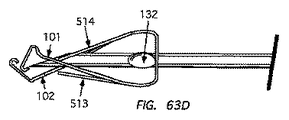
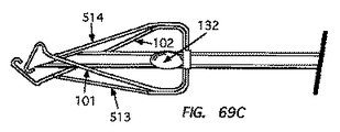
図9および図10は、ニードル・ガード100を示しており、そのニードル・ガード100は、ニードル130上の前記第2軸方向位置(second axial position、格納位置)にあり、このとき、ニードル先端134であって、斜部136の全体を含むものは、覆われている。一実施態様においては、ニードル・ガード100がニードル130上を移動させられるとともにリップ・セグメント111および112がニードル先端134から遠位方向に移動させられると、ニードル130上のプロファイル変化部132がベース118の開口部119に係合することにより、ニードル・ガード100が前記第2軸方向位置において停止させられる。停止のための他のいくつかの実施態様が後述される。長手部材152の長さは、次のようにして選択され、その選択は、プロファイル変化部132が例えばベース118内の開口部119に係合する状態で、ニードル130の遠位先端134および斜部136の全体が貫通通路153内に留置されるように配置されるとともに、アーム101および102の遠位セクション107および108のうちの少なくとも1つが、長手部材152のうちの遠位端156を完全にまたは少なくとも部分的に覆う(cover、被覆する、保護する)ことを目的として、ニードル130から離脱して(disengage with、ニードル130との係合が解除されて、ニードル130の側面との係合が解除されて)前進することが可能となるように、行われる。
9 and 10 show a
一実施態様においては、図7に示すように、ニードル・ガード100が前記準備位置(前記第1軸方向位置)にある場合に、アーム101の遠位セクション107がニードル軸線(中心線)に対して第1角度を有するように構成されるとともに、ニードル・ガード100が前記準備位置にある場合に、アーム102の遠位セクション108が、ニードル軸線に対して第2角度を有するように構成され、このとき、その第2角度は、前記第1角度より大きい。さらに、図9に示すように、ニードル・ガード100が前記第2軸方向位置にある場合に、アーム101の遠位セクション107は、長手部材152の縦軸(longitudinal axis、長手部材152の中心線)に対して実質的に直角となる位置関係を取るように、向きを有するとともに付勢されている。いくつかの実施態様においては、遠位セクション107の断面積(cross-sectional area、長手部材152を横切る面積)が、長手部材152の遠位端156の全部を覆う(cover、被覆する、保護する)のに十分な大きさである。別のいくつかの実施態様においては、長手部材152の遠位端156の全部より少ない部分が遠位セクション107により覆われる。
In one embodiment, as shown in FIG. 7, when the
上述のように、アーム101の遠位端(遠位セクション)107は、ニードル・ガード100が前記第2軸方向位置を取る場合に、遠位端(遠位セクション)107が、下向き/近位方向に作用する力を長手部材152の遠位端156に作用するように、付勢される(biased)ことが可能である。一実施態様においては、その付勢が、リージョン(ヒンジ部)117内の弾性ヒンジによって実現される。前記下向き/近位方向に作用する力を作用させることは、全体的または部分的なシール部の形成を支援し、そのシール部は、ニードル・ガード100前記第2軸方向位置を取るに至った後に、ニードル130および長手部材152のそれぞれの内腔内の汚染物質がニードル・ガード100から漏れ出すことを制限または阻止することが可能である。いくつかの実施態様においては、アーム102の遠位端(遠位セクション)108は、遠位端(遠位セクション)107に対して傾斜した角度を有することと、ある力を、遠位端(遠位セクション)107上に、かつ、長手部材152の遠位端156に向かう方向に作用させることとを行うように、配向されるとともに付勢されている。
As described above, the distal end (distal section) 107 of the
いくつかの実施態様においては、図38に示すように、ニードル・ガード100が、血管内(intravenous)カテーテル(カテーテル・アセンブリ)700の一部を形成しており、それら実施態様においては、凸部117および116が、アーム101および102上にそれぞれ形成され、その目的は、カテーテル・アセンブリ700が準備位置にある場合に、ニードル・ガード100をカテーテル・ハブ702内に離脱可能に固定するために、カテーテル・ハブ702の内部にある1または複数の特徴部703に係合することにある。
In some embodiments, the
前述のように、従来のスプリング・クリップ式(弾性を有するクリップを利用する形式)のニードル・ガード・デバイスに関する問題は、いくつかの力が、スプリング・クリップ式のいくつかのアームのうちのいくつかの部分に作用し、それが原因で、いくつかの遠位アーム・セクション(アームのうちの遠位セクション)が外向きに強く押される(urged outward)ということである。このことにより、当該ニードル・ガードが保護位置(protected position、ニードルが被覆されて保護される位置)を取るに至った後に、いくつかの遠位アーム・セクションがニードル先端を保護することを止めてしまう(move away from)可能性が生じる。この問題に対処するため、本発明のいくつかの実施態様においては、ニードル・ガード100の第1部分110が、アーム・セグメント113および114であって、各々、完全にまたは実質的に直線的であるものを有しており、それらアーム・セグメント113および114は、それぞれ、遠位アーム・セクション107および108より近位寄りの位置に配置されている。図9に示すように、ニードル・ガード100がニードル130上の前記第2軸方向位置を取る場合に、アーム・セグメント113および114は、長手部材152の外面の両側にそれぞれ当接し、かつ、長手部材152の外面の両側位置において側方に(laterally、側面に関して)配置されるように、アーム・セグメント113および114が配置されている。アーム・セグメント113および114は、ニードル・ガード100が前記第2軸方向位置にある場合に、遠位セクション107および108と、アーム101および102の交点126との間のいくつかの位置を占有するように配置されている。一実施態様においては、アーム・セグメント113および114が、遠位セクション107および108にそれぞれ隣接するように配置されるとともに、アーム101および102の交点126からある距離だけ遠位方向に離れるように配置されている。一実施態様においては、アーム・セグメント113が交点126から遠位方向に離れる距離D1が、L1・sinβ以上であり、ここに、L1は、交点126と、アーム101が長手部材152の外周面と交差する位置との間の距離にほぼ等しく、また、βは、アーム101と、交点126を通過し、かつ、長手部材152の縦軸(中心線)に対して直角であるように延びる一直線との間の角度である。不可欠ではないが、アーム・セグメント114は、アーム・セグメント113に対して実質的に軸方向に(longitudinally,長手方向に)位置合わせされる(aligned with、縦軸方向における位置が互いに一致する)ように、交点126から遠位方向に離れることが望ましい。
As mentioned above, the problem with the conventional spring clip type ( a type that utilizes elastic clips ) needle guard devices is that several forces are applied to some of the several spring clip type arms. Acting on that part, which is why some distal arm sections (distal sections of the arms) are urged outward . This prevents some distal arm sections from protecting the needle tip after the needle guard has reached a protected position (protected position). There is a possibility of moving away from. To address this problem, in some embodiments of the present invention, the
いくつかの実施態様においては、アーム・セグメント113および114のそれぞれの幅寸法が、それぞれ、遠位セクション107および108のそれぞれの幅寸法と実質的に同じである。他のいくつかの実施態様においては、図6Bに示すように、アーム・セグメント113および114が、それぞれ、遠位セクション107および108の幅寸法より小さい幅寸法を有する。他のいくつかの実施態様においては、アーム・セグメント113および114のうちの一方または双方が、円弧状部を有することが可能であり、その円弧状部は、長手部材152の外側曲線部(curvature、曲率部、曲率、外周面の曲率)のうちのいくつかの部分に少なくとも部分的に一致する(confirm、形状的に一致する、適合する、幾何学的に適合する)。このような構成態様による効果は、不適切な力がアーム101および102のうちの一方または双方に作用する場合に、アーム・セグメント113および114の、長手部材152の外面に対する少なくとも部分的な形状適合性(confirmability)が、アーム・セグメント113および114の、長手部材152周りの安定性を高める(長手部材152の周りをみだりに動かない)ように作用するということである。すなわち、上述の少なくとも部分的な形状適合性は、不適切な力がアーム101および/または102に作用する場合に、それらアーム101および/または102が長手部材152の外面上を側方に(sideways、前記外面である円周面に沿ってそれの周方向に、前記外面上をそれから側方に離れる方向に)にスリップしてしまう可能性を軽減するのである。一例として、かつ、図6Aを参照するに、アーム・セグメント113の外側エッジ121および122は、それぞれ、切断線123および124に沿って内向きに(inward、自身の中心に向かう向きに)湾曲し、それにより、それら外側エッジ121および122は、部分的に曲線的である構成態様を取る。
In some embodiments, the respective width dimensions of
ニードル・ガード100の第1部分110および第2部分150は、種々の構成態様のうちのいずれでも取ることが可能である。図6Aおよび図6Bを再び参照するに、一実施態様においては、アーム101および102のそれぞれの中央セクション105および106が、長手部材152を収容するほどに十分に狭く、このとき、第1部分110が、図7−図10に例示するように、スプリング式クリップ(弾性クリップ)となるように形成される場合に、それら中央セクション105および106と長手部材152の外面との間にクリアランスが存在する。図6Aおよび図6Bにおける複数本の破線は、スプリング式クリップの製造方法の実行中に複数の曲がり部および/または複数のヒンジ部を生成するための複数の折り曲げ位置(folding locations、折畳み位置)を示している。
The
いくつかの実施態様においては、長手部材152が、1または複数の材料を有し、その材料は、使用中の座屈に耐えるのに十分な剛性を有する。その1または複数の材料は、種々の組成物(composition of materials、複数の材料の合成物)、例えば、金属、エラストマー/プラスチック、編み上げ構造体(braided structure)、不規則に束ねられた構造体(random stranded structure)、それらの組合せなどのうちのいずれでも有することが可能である。長手部材152は、複数の部分またはセクションであって長手部材152を形成するために互いに結合されるものを有することが可能である。
In some embodiments, the
長手部材152は、例えば、深絞り製造方法(deep-draw fabrication process)を用いて製造することが可能であり、その深絞り製造方法においては、金属材料が、その絞り工程中に加工硬化(work hardened)させられ、それにより、仕上げ後の部品の表面を二次的に熱処理することが不要となる。長手部材152は、さらに、例えば、エラストマ−/プラスチック製のチュービングの押出し部(an extruded portion of elastomer/plastic tubing、押出し成形品)を有することも可能である。
The
他のいくつかの実施態様によれば、長手部材152のうちの近位部内の貫通通路153であってベース118に隣接するかまたは近接するものが、他の部分より小さい断面積/直径(小径部)を有し、そのような他の部分より小さい断面積/直径が原因で、貫通通路153のうちの近位部が、ニードル・シャフト131上のプロファイル変化部132に係合する。一実施態様においては、貫通通路153のうちの上述の小径部が、ベース118内の開口部119に代えて、ストッパとして作用し、その目的は、ニードル130上のニードル・ガード100の移動限度位置を前記第2軸方向位置に設定することにある。他のいくつかの実施態様においては、小径のブッシュまたはスリーブが、ストッパとして作用するために、長手部材152の近位端154と同じ位置に配置されるか、または、その近位端154に連結されることが可能である。
According to some other embodiments, the through-
他のいくつかの実施態様によれば、長手部材152のうちの近位部が、図9に示す方法でプロファイル変化部132上において(over、乗り越えるように)拡径(expand、膨張)または屈曲する(flex、撓む、曲がる)ことが可能である材料を有する。一実施態様においては、長手部材152のうちの近位部が、弾性材料を有し、その弾性材料は、プロファイル変化部132上において(over)拡張すると同時に、そのプロファイル変化部132上に拘束(constraining、束縛、圧迫)力/半径方向力を作用させることが可能である。そのような実施態様の利点は、ニードル130の遠位端を覆うようにニードル・ガード100が位置決めされた後、プロファイル変化部132に作用する半径方向拘束(constraining、束縛、圧迫)力が、長手部材152の側方移動を制限するように作用するということである。このことは、特に、遠位セクション107またはアーム101と長手部材152の遠位端156との間に形成される全体的なまたは部分的なシール部が必要である場合に、有利である。他のいくつかの実施態様によれば、長手部材152の全体が、フレキシブルな材料を有し、そのフレキシブルな材料は、長手部材152がニードル130の遠位端までスライドまたは移動させられるにつれて、ニードル130のプロファイル変化部132上において長手部材152が拡張または屈曲することを可能とする。
According to some other embodiments, the proximal portion of the
図13は、長手部材152の一実施態様を示す側面断面図であり、その長手部材152は、内径が縮径された近位部155を有する。長手部材152は、吸収性をもしくは多孔性を有する内側コーティング/膜/ライナまたはそれと同様な部材158を有してもよく、その吸収性/多孔性部材158は、ニードル130の外径に接触し、そのニードル130が長手部材152を通過するようにスライドまたは移動するにつれて、ニードル130の外面から血液または体液を吸収または拭うことが可能であるサイズを有する。吸収性/多孔性部材158は、ニードル130の内腔内に残存する血液または体液を吸収してもよい。いくつかの実施態様においては、吸収性/多孔性部材158が、例えば、抗微生物剤(antimicrobial agent)または抗生剤(antibiotic agent)のような薬剤を含有する。
FIG. 13 is a side cross-sectional view illustrating one embodiment of the
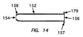
図14は、長手部材152の一実施態様を示す側面断面図であり、その長手部材152は、小径部または円錐台状部159を近位端154において有するとともに、遠位フランジ(flange、半径方向外向きに張り出したつば)157を遠位端156において有する。一実施態様によれば、遠位フランジ157は、より大きな接触面179を提供し、その目的は、ニードル・ガード100がニードル130上の前記第2軸方向位置にある場合に、アーム101の遠位セクション107と、長手部材152の遠位端156との間にシール部を形成することを促進することにある。他のいくつかの実施態様においては、ニードル・ガード100がニードル130上の前記第2軸方向位置に至ると、リップ(リップ・セグメント)111が遠位フランジ157に係合して、アーム101の遠位セクション107が長手部材152の遠位端156に固定されるように、遠位フランジ157とアーム101のリップ(リップ・セグメント)111とが構成される。このような実施態様においては、遠位フランジ157が、環状であるか、連続的であるか、または断片化されている(segmented、連続体として構成されるのではなく、複数のセグメントに分割されている)。
FIG. 14 is a side cross-sectional view illustrating one embodiment of a
図15は、長手部材152の一実施態様を示す断面図であり、その長手部材152は、小径部または円錐台状部160を有し、その円錐台状部160は、他の部位より小径である端セクションまたはスリーブ(近位端セクション)161に至るまでの遷移部(transitioning)として作用する。長手部材152は、さらに、遠位フランジ(flange、半径方向外向きに張り出したつば)157を有することも可能である。一実施態様においては、近位端セクション161が、長手部材152の近位端154をベース118に装着するために用いられる。その装着は、圧縮成形(stamping、スタンピング)、圧入(pressing)または他の機械的な締結方法によって達成することが可能である。例えば、近位端セクション161は、複数のタブまたはそれと同様な他のものであってベース118内に実現された開口部119または他のオープニング内に挿入されて固定される(fixed into、固着される)ものを形成するように、断片化する(segmented、連続体として構成されるのではなく、複数のセグメントに分割されている)ことが可能である。他のいくつかの実施態様においては、近位端セクション161の形状およびサイズにより、その近位端セクション161が、開口部119内に圧入されて固定されることが可能である。注目することが重要なことは、他の種々の装着方法またはそれらの組合せのうちのいずれでも、本明細書に開示されるとともに本発明の対象として考慮される長手部材152をニードル・ガード100のベース118に装着するために用いることが可能であるということである。それらの方法は、接着剤の使用、半田付け、溶接、機械的装着などを含むことが可能である。後に詳述するように、いくつかの実施態様においては、長手部材152が、ニードル・ガード100の第1部分110と一体的に形成される。
FIG. 15 is a cross-sectional view showing one embodiment of the
長手部材152のうちのある長さを有する部分に沿って、小径を有する複数のエリア/セクションを実現する利点は、それらエリア/セクションが、長手部材152がニードル130上に同軸的に配置されることが維持されることを支援するということであり、その同軸的配置により、長手部材152がニードル・シャフト131に沿って移動させられる際に、そのような同軸的配置が実現されないと存在するであろう摩擦力または引き摺り力が減少する。それらエリア/セクションは、さらに、長手部材152がニードル・シャフト131に対して同軸的位置関係を有することを強制または維持することも支援する。
The advantage of realizing a plurality of areas / sections having a small diameter along a portion of the
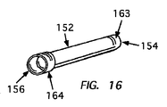
図16は、長手部材152の一実施態様を示す斜視図であり、その長手部材152は、大径遠位部164と、小径近位部163とを有する。図17は、図16に従う長手部材152の一実施態様を示す断面図であり、その長手部材152は、大径遠位部164内の空洞(cavity、キャビティ)内に保持された内側のリングまたはブッシュ165であり、それら内側のリングまたはブッシュ165は、ニードル130を長手部材152内において同軸的に位置決めすることと、ニードル130が長手部材152内を通過するようにスライドまたは軸方向に移動する場合に、血液または体液をニードル130の外面から拭き取ることとを行うように配置される。大径遠位部164の利点の一つは、その大径遠位部164が、ニードル130の外面から拭き取られるかまたはニードル130の内腔から出現する血液または体液を収集するリザーバ(reservoir、収容する容器)を提供するということである。一実施態様においては、そのリザーバが、前記血液または体液を吸収するコーティングまたは吸収材を含有する。一実施態様においては、その吸収材が、前記リザーバ全体またはそのうちの大部分を占めるとともに、ニードル130の遠位端が長手部材152の前記リザーバ部内に導入されることを許容する程度の変形可能性または貫通可能性を有する。いくつかの実施態様においては、長手部材152の遠位端と遠位アーム・セクション107との間にシール部が実現され、それら実施態様においては、1または複数の開口部が前記リザーバの壁部内に実現されることが可能であり、その目的は、流体固着現象(hydraulic lock、非圧縮性流体による機械的部品の固着)を阻止することにある。一実施態様においては、前記リザーバの壁部内の前記1または複数の開口部が、血液または体液が前記壁部を貫通することを防止または阻止するほどに十分に小さい。
FIG. 16 is a perspective view showing one embodiment of the
いくつかの実施態様においては、内側シール部材または外側シール部材が、長手部材152の近位端154と同じ位置またはそれの近傍位置に設けられる。
In some embodiments, an inner seal member or an outer seal member is provided at the same location as or near the
いくつかの実施態様においては、長手部材152が、1または複数の、密閉された環状のリング、リブまたはセグメントであって、ニードル・ガード100がニードル130を覆うように前進させられる際、プロファイル変化部132上において変形または撓むものを有する。いくつかの実施態様においては、長手部材152が、複数の、長手状カプセル化部分(elongate encapsulated portions、長手状被包性部分)を有し、それら長手状カプセル化部分は、長手部材152の全長または一部の長さにわたって延びている。そのような実施態様においては、それらカプセル化構造体(長手状カプセル化部分)が、押出し成形を用いることによって形成されることが可能である。それらカプセル化部材(長手状カプセル化性部分)は、複数の化学物質を含有し、それら化学物質は、前記1または複数のカプセル化部材がプロファイル変化部132上において拡張するにつれて、互いに相互作用することが引き起こされ、さらに、それら化学物質は、長手部材152の近位端154をニードル130のプロファイル変化部132に固定するために固化することが引き起こされる。
In some embodiments, the
上述のように、ニードル・ガード100が前記第2軸方向位置に位置決めされた場合に、アーム101の遠位セクション107と、長手部材152の遠位端156との交点において部分的または完全なシール部(seal)を形成することが要求される可能性がある。いくつかの実施態様によれば、遠位セクション107の内面が、ある材料、化合物または薬剤(agent)によってコーティングされる(coated、被覆される)かまたは積層化され(laminated)、それら材料は、遠位セクション107が長手部材152の遠位端156に接触すると長手部材152の遠位端156によってシール部(seal)が形成されることに寄与する。逆に、または、遠位アーム・セクション107の内面をコーティングするかまたは積層化することに関連付けて(in conjunction with、と組み合わせて)、長手部材152の遠位端156を、シール部の形成に寄与する材料(material、シーリング材)、化合物(compound、シーリング化合物)または薬剤(agent、シーリング剤)を用いてコーティングまたは積層化することも可能である。例えば、いくつかの実施態様においては、遠位セクション107および遠位端156のうちの一方または双方が、それら部材間に全体的または部分的なシール部(seal)を形成するためにエラストマー(elastomer、ゴム状弾性体)のような変形可能材料(formable material、自身の形状が変化する材料、変形可能な材料)を含有する。他のいくつかの例は、粘着性を有する物質または接着剤を含有する。他のいくつかの例は、エラストマー製のOリングのうちの少なくとも一部を長手部材152の遠位端156上に、そのOリングのうちの少なくとも一部が遠位端156より遠位寄りの位置まで延び、それにより、そのOリングが遠位アーム・セクション107の接触面にかみ合う(mate with)ように、固定することを含む。他のいくつかのシーリング方法も本発明の対象として考慮される。
As described above, a partial or complete seal at the intersection of the
図18および図19は、別の実施態様に従うニードル・ガード200を示している。そのニードル・ガード200は、前述のニードル・ガード100のそれと同様であるが、アーム102の終端がセグメント114に位置し、そのセグメント114は長手部材152の外面に装着される点では、ニードル・ガード100とは異なる。一実施態様においては、セグメント114が、長手部材152の外面の曲率と同じであるかまたはほぼ同じである曲率を有する装着面を実現するように曲線的である。他の実質的にすべての点では、ニードル・ガード200の第1部分110および第2部分150のいくつかの実施態様が、前述のようにニードル130の遠位端の被覆を実現するのと同じ方法で機能する。注目することが重要なことは、アーム102が、長手部材152の外面に、より近位寄りのいくつかの部位において固定されることが可能であるということである。例えば、アーム102は、より短い長さ寸法を有することが可能であり、このとき、アーム102の端部は、長手部材152の長さに沿ったいずれの位置にも装着される。他のいくつかの実施態様においては、アーム102が、省略され(eliminated altogether)、このとき、長手部材152の近位端154がベース118に強固に連結される。
18 and 19 show a
他のいくつかの実施態様によれば、ニードル・ガード100の第1部分110および長手部材152が一体的に構成される。一実施態様においては、この一体構造が、長手部材152を形成するためにニードル・ガード100のベース118に対して深絞り加工を施すことによって達成される。この方法では、長手部材152は、ベース118内の開口部119から延びている(co-extensive to、開口部119から上方に延びている、開口部119の向きと同じ方向に延びている)ものとして説明することが可能である。一実施態様によれば、その一体構造の製法においては、最初に、図6Cに示すように、金属ストリップ50が形成され、その金属ストリップ50は、ニードル・ガード100のベース118を形成するように設計されたエリア52を有する。いくつかの実施態様においては、その金属ストリップ50が、一様な厚さ寸法を有し、一方、他の実施態様においては、金属ストリップ50が、少なくともリージョン54において、他の部位より拡大された厚さ寸法を有し、そのリージョン54は、長手部材152を形成するために前記深絞り加工法が施されるべき領域である。いくつかの実施態様においては、長手部材152を深絞りするのに先立ち、アーム・セクション101および/または102が、例えば図6Aに示すように、長手部材152の深絞りに先立って形成され(form、成形され)、一方、他のいくつかの実施態様においては、長手部材152が形成された後に、アーム・セクション101および/または102が形成される。いくつかの実施態様においては、その製造方法が、一様で、かつ、拡大された厚さ寸法を有する金属シートから開始され、続いて、その金属シートが、アーム・セクション101および/または102が存在する(reside)ように設計されるエリア56および58において平坦化される。その平坦化工程は、前記深絞り加工法を用いて長手部材152を形成する前または後に行うことが可能である。その平坦化工程に関連付けられる(in conjunction with、並行する、組み合わせて用いられる)か、またはその平坦化工程に後続して、それによって薄肉化された1または複数のエリア(56,58)のうちの少なくとも一部が、アーム・セクション101および/または102のうちの少なくとも一部を生成するために切断される。
According to some other embodiments, the
図13−図17を参照するに、1または複数の特徴部155,159,160,161,163および164が、前記深絞り加工中に、長手部材152となるように形成されることが可能であり、その深絞り加工方法は、前記1または複数の特徴部155,159,160,161,163および164を形成するのに適した寸法およびサイズを有する1または複数の型(die、ダイ)を用いて行われる。例えば、一実施態様においては、長手部材152の、円錐台状部160および小径端セクション161が、前記深絞り加工中に形成される。特徴部160および161のうちの一方または双方を長手部材152に組み込むことによる利点は、それら特徴部160,161により、長手部材152の近位セクションが、組立工程中に、ニードル130上に自動的に芯出しされることが可能となるということである。
Referring to FIGS. 13-17, one or
別の製造方法によれば、1枚の金属シートがニードル・ガード100の第1部分110を形成するという目的のために断片化されるのに先立ち、複数の長手部材152が、最初に、前記1枚の金属シートから、全体的にまたは少なくとも部分的に深絞りされる。
According to another manufacturing method, prior to a piece of metal sheet being fragmented for the purpose of forming the
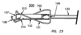
図20−図23は、別の実施態様に従うニードル・ガード・アセンブリ300を示している。そのニードル・ガード300は、前述のニードル・ガード100のそれと同様であるが、アーム・セグメント113および114が、円弧状の凹部313および314を有するように変形された点ではニードル・ガード100とは異なっており、それら凹部313および314は、長手部材152の外面の曲率と少なくとも部分的に一致するように構成されている。一実施態様においては、それら凹部313および314のうちの一方または双方が、半円部として構成されており、その半円部は、ニードル・ガード300が、ニードル130の遠位端を保護するために前記第2軸方向位置にある場合に、長手部材152の外側プロファイル(outer profile、外形形状)と一致する形状を有する。不適切な力がアーム101および102のうちの一方または双方に作用する場合にアーム101および102の遠位セクション107および108がニードル130の遠位端を覆わないように外向きに押し出されることを阻止することを目的として、凹部313および314の周方向エッジは、長手部材152の外面にもたれている(rest against、寄りかかっている、支持されている)。
20-23 illustrate a
図21に示すように、本明細書に開示されるとともに本発明の対象として考慮されるいくつかの実施態様に従うニードル・ガードを製造する方法は、最初に、図20に例示する弾性材料の平坦な一部品から、型抜き(stamp、スタンプ)、切断または他の方法で、ニードル・ガード300の第1部分310を形成することである。第1部分310が形成された後、長手部材152が、貫通通路153がベース118内の開口部119に対して軸方向に位置合わせされる(axially aligned、軸方向位置が一致する)ように、配置される。開口部119を貫通し、かつ、貫通通路153のうちの少なくとも一部を貫通するように延びる固定具が、長手部材152を支持するために用いられる可能性がある。他のいくつかの方法によれば、長手部材152の近位端154に外側小径セグメント169が設けられ、その外側小径セグメント169は、開口部119を貫通するかまたは他の方法で開口部119に固定され、その目的は、全体的にまたは部分的に長手部材152を、図21に示すように、第1部分310に対して直角である姿勢で支持することにある。一実施態様においては、長手部材152の近位端154の近傍位置に配置された小径環状リングが、長手部材152をベース118に固定することを目的として、長手部材152の近位端154をベース118の開口部119内にスナップ・フィットする(snap fit、材料の弾性を利用してはめ込んで固定する)手段を実現する。他のいくつかの実施態様においては、スリットまたはスロットが、ベース118内に実現され、そのスリットまたはスロットは、ベース118のサイド・エッジから開口部119まで延びている。この方法で、長手部材152に、小径環状リング部が、近位端154の近傍位置に設けられ、その小径環状リング部は、長手部材152をベース118に装着することを目的として、長手部材152が側方変位させられた後に(side loaded、前記スリットまたはスロット内を側方に移動させられた後に)開口部119内に固定される。長手部材152が第1部分310上に適切に支持されるかまたは第1部分310に適切に装着されると、その第1部分310は、全体的にまたは部分的に曲がることが可能であり、それにより、必要ないくつかのアーム部およびヒンジ部が全体的にまたは部分的に形成される。この時点で、第1部分310および長手部材152は、ニードル130上に装填されることが可能であり、このとき、第1部分310は、(必要なら)さらに曲がるとともに図22に示す方法でニードル130上に配置される。
As shown in FIG. 21, a method of manufacturing a needle guard according to some embodiments disclosed herein and considered as a subject of the present invention begins with the flatness of the elastic material illustrated in FIG. Forming a
いくつかの実施態様によれば、ニードル・ガード300の第1部分310および長手部材152が一体的に構成される。
According to some embodiments, the
図24は、別の実施態様に従うニードル・ガード350を示している。そのニードル・ガード350は、前述のニードル・ガード300のそれと同様であるが、アーム102の終端が、凹部(recess)314から遠位方向に少し離れた位置に位置する点では、ニードル・ガード300とは異なる。そのような実施態様においては、凹部314が、長手部材152の外面に連続的に接触しつつ押圧され、このとき、ニードル・ガード350がニードル130上の前記第2軸方向位置にある場合に、アーム101の遠位セクション107が長手部材152の遠位端156を単独で(singularly)覆うように位置させられる。ニードル・ガード350のアーム101および102であって本明細書に開示されているとともに本発明の対象として考慮されるものは、図24に例示されているように、形式が互いに異なる複数の特徴部を有し、図24においては、アーム102が、長手部材152の外面に当接する凹部314を有するとともに、アーム101が、長手部材152の外面に当接する長手面(elongate surface、軸方向面、細長面)113を有する。
FIG. 24 shows a
いくつかの実施態様によれば、図24に示すニードル・ガード350の第1部分および長手部材152が一体的に構成される。
According to some embodiments, the first portion of
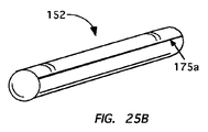
いくつかの実施態様によれば、図25Aに示すように、長手部材152が、弾性構造体170を有し、その弾性構造体170は、互いにオーバラップする縦軸方向部171および172を有し、それら縦軸方向部171および172は、長手部材152の長さに沿って、縦軸方向スリットまたはスロットを一時的に形成するために互いに分離可能であり、それにより、長手部材152が側方変位後に(side-loaded、縦軸方向部171および172が互いに接近する向きに側方変位させられた後に)ニードル130に押し付けられる。図25Aは、長手部材152の平面図を示している。長手部材152が側方変位後に(side-loaded)ニードル・シャフト131に押し付けられると、弾性構造体170は、全体的にまたは部分的に初期形状に回復し、それにより、ニードル・シャフト131の外周を完全に包囲する。一実施態様においては、弾性構造体170が、エラストマー材を有し、そのエラストマー材は、上述の互いにオーバラップする縦軸方向部171および172の接触面同士が互いに接触すると、それら縦軸方向部171および172に沿ってシール部が形成されることを促進する表面特性を有する。他のいくつかの実施態様においては、弾性構造体170が金属を有する。いくつかの実施態様においては、縦軸方向部171および172のそれぞれの、互いにオーバラップする接触表面のうちの一方または双方が、長手部材152の長さに沿ってシール部を形成することを誘発する物質で表面処理されるかまたは他の方法でコーティングされる。他のいくつかの実施態様においては、シール部が、互いにオーバラップする縦軸方向部171および172間に、超音波溶接方法または他の同様な方法を用いて形成される。
According to some embodiments, as shown in FIG. 25A, the
他のいくつかの実施態様においては、図25B−図25Dに示すように、長手部材152が、1または複数のスリット175a,175bを有し、それらスリット175a,175bは、長手部材152を側方変位後に(side loading)ニードル・シャフト131に押し付けることを促進するために分離可能である。図25Aに示すいくつかの実施態様のうちの一部と同様に、長手部材152は、エラストマー材を有することが可能であり、そのエラストマー材は、スリット175a,175bの接触表面同士が互いに接触すると、それらスリット175a,175bのかみ合い面同士(mating surfaces)の間にシール部が形成されることを促進する特性を有する。他のいくつかの実施態様においては、スリット175a,175bのそれぞれの接触表面のうちの一方または双方が、長手部材152の長さに沿ってシール部を形成することを誘発する物質で表面処理されるかまたは他の方法でコーティングされる。他のいくつかの実施態様においては、シール部が、スリット175a,175bのそれぞれのかみ合い面同士の間に、超音波溶接方法または他の同様な方法を用いて形成される。
In some other embodiments, as shown in FIGS. 25B-25D, the
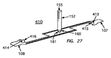
図26−図31は、別の実施態様に従うニードル・ガード・アセンブリ400を示している。そのニードル・ガード400は、前述のニードル・ガード100のそれと同様であるが、アーム・セグメント113および114が、被成形部(formed portions、予め成形された部分、所定形状を有するように成形された部分)413および414を有するように変形されている点ではニードル・ガード100とは異なっており、それら被成形部413および414は、長手部材152の外面の曲率と少なくとも部分的に一致するように構成されている。長手部材152の近位セクションは、さらに、図15に示すそれと同様に、円錐台状部160と、小径部161とをさらに有している。一実施態様においては、ニードル・ガード400が、ニードル130の遠位端を保護するために前記第2軸方向位置にある場合に、それら被成形部413および414のそれぞれの近位エッジ415および416のうちの一方または双方が、長手部材152の外側プロファイルと一致する形状を有する。実際、図29に示すように、不適切な力がアーム101および102のうちの一方または双方に作用する場合にアーム101および102の遠位セクション107および108がニードル130の遠位端を覆わないように外向きに押し出されることが阻止されることを目的として、ニードル・ガード400が前記第2軸方向位置にある場合に、被成形部413および414の内面は、長手部材152の外面にもたれかかっている(rest against、寄りかかっている、支持されている)。図30は、ニードル・ガード・アセンブリ400を、それがニードル130上の前記第1軸方向位置にある状態で示す斜視図である。図31は、ニードル・ガード・アセンブリ400を、それがニードル130上の前記第2軸方向位置にある状態で示す斜視図である。
26-31 illustrate a
いくつかの実施態様によれば、ニードル・ガード400の第1部分410および長手部材152が一体的に構成される。
According to some embodiments, the
図24に関連付けて前述した実施態様と同様に、ニードル・ガード400は、アーム102の終端が、被成形部414から遠位方向に離れた位置にちょうど位置するように変形されることが可能であることが理解される。このような実施態様においては、被成形部414が、長手部材152の外面に連続的に接触しつつ押圧され、このとき、アーム101の遠位セクション107は、ニードル・ガード400がニードル130上の前記第2軸方向位置にある場合に、長手部材152の遠位端156を単独で覆うように位置させられる。
Similar to the embodiment described above in connection with FIG. 24, the
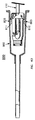
図61は、ニードル・ガード・アセンブリを示しており、そのニードル・ガード・アセンブリは、図30に示すものと似ているが、いくつかの相違する特徴(distinguising features、他から区別される特徴)も存在する。第1の相違する特徴は、ニードルの構成態様にある。図30のアセンブリにおいては、不連続の(discrete、周辺と連続していない周辺から離散している)プロファイル変化部132が、ニードルの遠位端セクションのうち、遠位先端134の近傍位置に位置する制限手段(limiting means、移動制限手段、停止手段、リミッタ、ストッパ)として設けられているが、図61のアセンブリにおいては、その制限手段が、周辺部より直径が拡大された長手状セクション(elongate section、長さを有するセクション)401であってニードルの遠位端に位置するもののうちの近位寄りの肩部402を有する。別の相違する特徴は、長手部材の構成態様にある。図30の実施態様においては、長手部材152の近位セクションが、周辺部より直径が縮小された小径部161を有しており、その小径部161は、ニードル・ガードがニードルの遠位先端134を覆うためにニードル・ガードが作用させられている場合に、ニードル・ガードをニードル上に停止させることを目的として、ニードル上のプロファイル変化部132に対して作用するように構成される。図61の実施態様においては、長手部材408が、直径が一様である直径不変構造部を有し、その直径不変構造部は、タング(tongue、細長い突起部)409を有し、そのタング409は、長手部材408の近位端セクションに切れ目が入れられることによって形成されている(cut into)。タング409は、ひとたび形成されると、当該タング409のうちの少なくとも一部が長手部材408内に留置されるように、内向きにクリンプされる(crimped、波形化される、折り目が付けられる)かまたは曲げられる(bent)。タング409のうち、長手部材408内に留置される部分は、ニードル・ガードがニードルの遠位先端403を覆うためにニードル・ガードが作用させられている場合に、ニードル・ガードをニードル上に停止させることを目的として、ニードル上の肩部402と係合するように構成される。いくつかの実施態様においては、2またはそれより多数のタングが設けられる。
FIG. 61 shows a needle guard assembly that is similar to that shown in FIG. 30, but with some different features (distinguising features). Is also present. The first different feature is the configuration of the needle. In the assembly of FIG. 30, the
注目することが重要なことは、本明細書において開示されている(この位置より前方および後方に開示されている)多数の特徴部であってニードル・ガードに関するもの(needle guard features)のうちの多くは、本明細書に開示されているとともに本発明の対象として考慮されている多数の実施態様の間において相互に置換することが可能であるということである。例えば、それぞれの実施態様は、特徴部113,114と、他の特徴部313,314と、他の特徴部413,414とを開示しているが、それら特徴部113,114,313,314,413,414を、本明細書に開示されている複数の発明に従い、1つのニードル・ガードに組み込むことが可能であることが理解される。さらに、一例として、本明細書に開示されている種々の長手部材152および長手状特徴部は、本明細書に開示されているとともに本発明の対象として考慮されている多数の実施態様の間において相互に置換する。
It is important to note that among the many guard guard features disclosed herein (disclosed forward and backward from this position) that relate to needle guard features. Many are interchangeable among the many embodiments disclosed herein and considered as the subject of the present invention. For example, each embodiment discloses
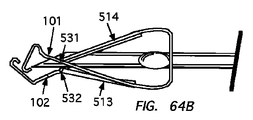
図32−図34は、ニードル・ガード・アセンブリ500を示しており、そのニードル・ガード・アセンブリ500は、前述のニードル・ガード・アセンブリ300と同様であるが、長手部材152の遠位端502が長手部材152の縦軸に対して傾斜する向き(orientation、配向)を有する点と、ニードル・ガード・アセンブリ500が図34に示すように前記第2軸方向位置にある場合にアーム101の遠位セクション107が、長手部材152の遠位端502の上述の傾斜配向を取ることを目的として、ある角度で延びる向きを有する(angularly oriented、傾斜している)点とで、前述のニードル・ガード・アセンブリ300とは異なっている。長手部材152の近位セクションは、さらに、図15に示すものと同様に、円錐台状部160と、小径部161とを有する。遠位セクション107は、ニードル・ガード500が前記第2軸方向位置にある場合に長手部材152の遠位端502にある力を作用させるように構成されることが望ましい。遠位セクション107の遠位端に位置するリップ504は、さらに、下向きに配置される(oriented in a downward facing position、下向き姿勢で配向される)とともに、長手部材152の、傾斜した遠位開口部を横切るための位置に位置決めされており、その目的は、圧縮力、すなわち、「つまみ動作(pinch)」がアーム101および102のうちの一方または双方に作用した場合に、アーム101のうちの遠位セクション107が長手部材152の遠位端502から分離することを阻止する機械的なストッパ機構を実現することにある。
FIGS. 32-34 illustrate a
いくつかの実施態様によれば、ニードル・ガード500の第1部分および長手部材152が一体的に構成される。
According to some embodiments, the first portion of the
圧縮力、すなわち、「つまみ動作(pinch)」がアーム101および102のうちの一方または双方に作用した場合に、アーム101のうちの遠位セクション107が長手部材152の遠位端502から分離することを阻止することを目的として、本明細書に開示されている種々の実施態様においては、下向きのリップを、遠位セクション107の遠位端に配置することが可能である。いくつかの実施態様においては、遠位セクション107の遠位端に配置されるリップと連動するために、インデンテーション(indentation、凹み)またはカーフ(kerf、切り口、切り溝)が長手部材152の遠位端502に設けられる。
The
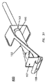
図35−図37は、別の実施態様に従うニードル・ガード600を示している。このニードル・ガード600は、第1部分610を有しており、その第1部分610には、長手部材652が組み込まれている。一実施態様においては、第1部分610が、第1アーム601および第2アーム602を有し、それらアーム601および602は、それぞれ、ベース618のうちの両側部から延びている。第1部分610は、弾性材料から成る1個の部品(piece、ピース)から製造されることが望ましく、その1個の部品は、ベース618と、アーム601および602と、それらの遠位セクション607および608とを形成するために折り曲げられる。ベース618内の開口部(図示しない)は、ニードル130の近位部136を収容することと、ニードル・ガード600が第1軸方向位置(図35および図36に示す)から、ニードル130の遠位端134を保護するための第2軸方向位置(図37に示す)まで遷移するにつれてニードル・シャフトに沿ってニードル・ガード600を案内することとを達成することとを行うためのサイズを有する。アーム601および602は、ベース618の位置においてヒンジ結合されるとともに、ニードル・ガード600が第1軸方向位置にあって、このとき、ニードル130の遠位端134が保護されていない場合に、ニードル130の外面と当接する位置関係を有するように構成されている。長手部材652は、近位端654と、遠位端656とを有し、この長手部材652に、それら近位端654と遠位端656との間を延びる、内部通路としての貫通通路653が設けられる。ニードル130は、近位シャフト部136と、次第に増加する直径(increasing diameter)を有するフレア付き遠位シャフト部138とを有する。使用中、長手部材652は、第1部分610の内部であって、ベース618と遠位セクション608との間の部分に配置されるように位置決めされる。一実施態様においては、長手部材652の遠位端656がニードル130の遠位先端まで延びるかまたはその遠位先端を超えて延びることが可能となるように長手部材652が前進させられるのに十分な直径を長手部材652の内部通路(貫通通路)653の全体が有する状態で、図37に示すようにニードル・ガード600を前記第2軸方向位置に停止させることを目的として、ベース618内の前記開口部が、フレア付き遠位シャフト部138と係合するサイズを有する。別の実施態様においては、長手部材652の近位端654に、ニードル・ガード600を前記第2軸方向位置に停止させるように作用する部分であって他の部位より小径である内径を有するものが設けられる。別の実施態様においては、スリーブまたはブッシュが、長手部材652の近位端654に配置され、それらスリーブまたはブッシュは、前記第2軸方向位置での停止を行うためのストッパとして作用するのに十分な直径を有する内部ボアを有する。
35-37 illustrate a
図37に示すように、長手部材652の遠位端656がニードル130の遠位端134の全体を覆う(cover、被覆する、保護する)ように配置された状態で、アーム601および602は、長手部材652の遠位端656を覆うことを目的として、ニードル・シャフトから離間するとともに、蓄積されているエネルギー(stored energy、蓄積されている弾性エネルギー)によって内向きに互いに押し付けられる。一実施態様によれば、アーム602の遠位セクション608が、位置620においてヒンジ結合され、その目的は、長手部材652の遠位端656に、下向き方向/近位方向に作用する力を作用させることにある。一実施態様においては、アーム601および602に、凸部619および620が設けられ、それら凸部619および620は、カテーテル・ハブのうちの1または複数の内部特徴部と相互作用し、それにより、ニードル・ガード600が、図38に関連して同様に説明される方法で、前記カテーテル・ハブ内において離脱可能に固定される。
As shown in FIG. 37,
いくつかの実施態様によれば、ニードル・ガード600の第1部分および長手部材652が一体的に構成される。
According to some embodiments, the first portion of the
上述のように、図38は、安全静脈内カテーテル・アセンブリ700であって一実施態様に従うものを、すぐに使用できる作用状態(a ready to use operative position)で示す側面図である。カテーテル・アセンブリ700は、ニードル130を有し、そのニードル130は、鋭利な遠位先端134を有し、このとき、内部の通路(internal lumen、内腔)が、近位端140から遠位先端134まで延びている。ニードル・シャフト(needle shaft、ニードル130のシャフト)上のプロファイル変化部132が、前述のように、ニードル・ガード100を前記第2軸方向位置に停止させるように機能する。ニードル130の近位端部が、複数の近位凸部706を有するニードル・ハブ704に装着され、そのニードル・ハブ704は、オスルアー接続具(male luer fitting)を装着するための複数の凸部706を有する。ニードル130の近位端140は、ニードル・ハブ704のフラッシュバック・チェンバ708内に配置されている。前述のように、カテーテル・ハブ702の内壁に配置された1または複数の特徴部703に凸部117および116が係合することにより、ニードル・ガード100がカテーテル・ハブ702内において離脱可能に固定される。カテーテル・ハブ702の近位端が、ニードル・ハブ704の遠位端に作動的に(operably、共同作用を行う状態で)係合させられる。血管に穿刺して筒状カテーテル710をその血管内に導入するためにニードル先端(遠位先端)134が露出させられるように、筒状カテーテル710は、カテーテル・ハブ702の遠位端から遠位方向に(distally、術者から遠ざかる向きに)、かつ、ニードル130と同軸の関係を有して延びるとともに、その筒状カテーテル710の終端が、ニードル先端134より近位寄りの(proximal、術者に近い)位置に位置させられる。使用中、筒状カテーテル710が患者の血管内に適切に導入されると、ニードル・ハブ704が近位方向に引っ張られ、それにより、ニードル先端134が患者から引き込まれて(retract、抜去されて)ニードル・ガード100内に格納される。ニードル130が引き込まれると、凸部117および116によって作用させられる外向き力により、ニードル・ガード100がニードル・ハブ(カテーテル・ハブ)702内において固定される。ニードル130上のプロファイル変化部132の位置と、ニードル・ガード100の寸法的特性との組合せにより、結果的に、プロファイル変化部132がニードル・ガード100上に停止させられている状態で、遠位先端134が長手部材152内に完全に収容される。遠位先端134が長手部材152の遠位端156に進入すると、遠位アーム・セグメント(遠位セクション)107および108が、ニードル・シャフトから離脱し、アーム101および102内に蓄積されているエネルギーにより、長手部材152の遠位端156が被覆されるように、遠位セクション107および108が、それぞれ内向きに押し付けられる。同時に、凸部116および117がカテーテル・ハブ702から離間し、それにより、ニードル・ガード100およびニードル130がカテーテル・ハブ702から完全に離脱することが可能となる。
As described above, FIG. 38 is a side view of a safe
図39および図40は、別の実施態様に従う静脈内カテーテル・アセンブリ800を示している。そのカテーテル・アセンブリ800は、前述のカテーテル・アセンブリ700のそれと同様である。相違点は、ニードル・ガード100がカテーテル・ハブ802内に離脱可能に固定される方法(manner、仕方、形式)にある。カテーテル・アセンブリ800においては、アーム101および102上に形成された凸部117および116を使用することに代えて、ニードル・ガード100のベースと同じ位置またはそれの近傍位置に配置される弾性タブ810および811が外向きに突出し、それにより、カテーテル・ハブ802の内壁の1または複数の特徴部803に係合する。弾性タブ810および811のそれぞれの外側係合面は、カテーテル・ハブ802の内壁の曲率と一致するように円弧状を成すことが望ましい。1または複数の特徴部803は、凹み、アンダーカット、空洞、溝、突出部など、前記内壁の周りに環状を成すかまたは離散的に存在するように構成されたものを有することが可能である。弾性タブ810および811は、外向き力を作用させるように構成され、その目的は、カテーテル・アセンブリ800が前記準備位置にあるか、または、ニードル130がニードル・ガード100内に格納される途上において、前記係合面(the engaging surfaces、弾性タブ810および811のそれぞれの外側係合面)が、1または複数の特徴部803に係合するようにすることにある。弾性タブ810および811の係合力は、ニードル130がニードル・ガード・ストッパに係合すると、近位方向に作用する力がニードル・ガード100に作用する場合に、1または複数の特徴部803(図40参照)から離脱することが可能であるように十分に小さい。
39 and 40 show an
図41は、ニードル・ガード・アセンブリ900を、ヒューバー・ニードル(Huber needle、フーバー針)上の保護位置にある状態で示しており、そのヒューバー・ニードルは、ニードル190の遠位端の近傍位置に、中心線変化部(a change in axis)、すなわち、屈曲部(bend)を有することを特徴としている。ニードル・ガード・アセンブリ900は、これまでに説明された複数の実施態様のうちの一部と多くの点で共通するが、ニードル190が長手部材952内の保護位置内に格納される際に、長手部材952の遠位部958が、前記中心線変化部をうまく通り抜ける(maneuver around)とともにカント(cant、横断勾配)を有することが可能であるように、長手部材952を貫通して延びる内部通路が構成されている。一実施態様においては、長手部材952の近位端セクション(近位セクション)960に、内径が小径であるセグメントであって、当該ニードル・ガードを前記中心線変化部に停止させるのに適切な長さを有するものが設けられる。他のいくつかの実施態様においては、十分な長さ寸法と、小径の内径とを有するスリーブが、長手部材952の近位端に装着されるかまたは他の方法で連結される。他のいくつかの実施態様においては、プロファイル変化部または拡張部が、前記停止を行うストッパとして機能するために、前記中心線変化部より近位寄りの位置に配置される。
FIG. 41 shows the
図42A−図42Dは、別のいくつかの実施態様に従う静脈内(intravenous、血管内留置)カテーテル・アセンブリ210を示している。その静脈内カテーテル・アセンブリ210は、図38の静脈内カテーテル・アセンブリ700に対し、弾性アーム101,102の遠位セクション107,108が、図42Aに示すように、ニードル・ガード100が前記準備位置にある場合に、付勢されてニードル・シャフト131に押し付けられることがない(not biased against)が、その代わりに、付勢されて長手部材212に押し付けられる(biased against)点で、異なっている。図42Dに示すように、一実施態様においては、長手部材212が、遠位セクション214と、それより小径の近位セクション216とを有する。近位セクション216の外径(outer diameter、外側直径)は、ベース118内の開口部119内に留置される程度に小さく、このとき、遠位セクション214のうち、少なくとも、近位セクション216に最も近接している部分の外径は、開口部119より大きい。近位セクション216の少なくとも一部の外径(outer diameter、外側直径)は、後に詳述されるように、スプリング・クリップ220のベース118が、近位セクション216の長さに沿って軸方向にスライドすることが可能であるのに十分な大きさを有する。
42A-42D illustrate an
図42Aおよび図42Bに示すように、前記準備位置においては、スプリング・クリップ220のベース118が、長手部材212の、周辺部より小径である近位セクション216上に(on、に接触する状態で)、かつ、遠位セクション214より近位寄りの位置において、ベース118が、周辺部より小径である近位セクション216に沿って軸方向に進行することを可能にするように提供された距離D1を有する状態で、留置される。一実施態様においては、前記準備位置にある場合に、スプリング・クリップ220の、長手部材212上の軸方向位置が、リップ・セグメント111,112が1または複数の凹部217,218内に係合することによってリリース可能な状態で(releasably、離脱可能な状態で)固定され、それら凹部217,218は、長手部材212の遠位端の近傍に位置する。別のいくつかの実施態様においては、他の複数の共同作用特徴部(co-operable features)であって他のものと共同して作用することが可能であるものが、前記準備位置にある場合に、スプリング・クリップ220の、長手部材212上の軸方向位置および回転方向位置の移動範囲を決める(delimit、移動限度を決める)ことをアシストするようにリップ・セグメント111および112に係合するために、長手部材212の遠位端の近傍位置に提供される。いくつかの実施態様においては、弾性アーム101,102の遠位セクション107,108が長手部材212の遠位端に対して適切な(properly、正規の)向きを有する(oriented、姿勢を有する)ように、凹部217,218により、スプリング・クリップ220が長手部材212上を回転する能力が邪魔されるかまたは制限される。いくつかの実施態様においては、1個の凹部のみ(または他の1個の特徴部であって運動を制限するもの)が、スプリング・クリップ220の、長手部材212上の位置の移動範囲を決める(delimit、移動限度を決める)ために、長手部材212の遠位端の近傍位置に提供される。
As shown in FIGS. 42A and 42B, in the ready position, the
ある実施態様においては、図52に示すように、前記長手部材上の前記共同作用特徴部(cooperating feature)が、環状リング213を有しており、その環状リング213は、リップ・セグメント111,112のそれぞれの上部(upper portions、先端部)が載置される凹部217,218を有する。一実施態様においては、図52に示すように、環状リング213によって横切られる平面が、前記長手部材の長軸(longitudinal axis、長手軸線)に対して傾斜している。他のいくつかの実施態様においては、前記長手部材が遠位端223を有し、その遠位端223は、前記長手部材の長軸(longitudinal axis、長手軸線)に対して実質的に直角である。このような実施態様においては、図53に示すように、環状リング224によって横切られる平面も、前記長手部材の長軸(longitudinal axis、長手軸線)に対して直角であるように配置されることが可能である。図52および図53のそれぞれの実施態様においては、それぞれの環状リングを、リップ・セグメント111および112のそれぞれに係合するために、前記長手部材の表面上に前記長軸に対して傾斜して配置された第1のセクションおよび前記長軸に対して直角に配置された第2のセクション(first and second sections that are angularly and longitudinally situated)であってそれぞれ隆起している(raised、第1および第2のセクションが前記長手部材の表面より隆起している)とともに互いに分離している(discrete、第1および第2のセクションが互いに空間的に離散している)ものによって置換することが可能である。いずれの図面にも示されていないいくつかの他の実施態様においては、スプリング・クリップ220が前記準備位置にある場合に、前記長手部材の表面上の複数の隆起特徴部(raised features、隆起部)が、スプリング・クリップ220が前記長手部材上を軸方向および回転方向に運動することを制限する(impede)ために、リップ・セグメント111,112を収容するための複数のポケット(pocket、穴、くぼみ、受け口)を形成する。
In one embodiment, as shown in FIG. 52, the cooperating feature on the elongate member includes an
前述のように、スプリング・クリップ220は、凸部116および117がカテーテル・ハブ702の内壁上に位置する1または複数の特徴部703に係合することにより、リリース可能な状態で(releasable、離脱可能な状態で)、カテーテル・ハブ702内において固定される。カテーテル・ハブ702の近位端は、ニードル・ハブ704の遠位端に、共同作用を行うように(operably)係合させられる。血管に穿刺して筒状カテーテル710をその血管内に挿入するためにニードル先端(遠位先端)134が露出させられるように、筒状カテーテル710は、カテーテル・ハブ702の遠位端から遠位方向に(distally、術者から遠ざかる向きに)、かつ、ニードル130と同軸の関係を有して延びるとともに、その筒状カテーテル710の終端が、ニードル先端134より近位寄りの(proximal、術者に近い)位置に位置させられる。使用中、筒状カテーテル710が患者の血管内に適切に挿入されると、ニードル・ハブ704が近位方向に引っ張られ、それにより、ニードル先端134が患者から抜去されて(retract)ニードル・ガード内に格納される。ニードル130が抜去される(withdrawn)と、凸部117および116によって作用させられる外向き力により、ニードル・ガードがカテーテル・ハブ702内において固定され、同時に、スプリング・クリップ220が、凹部217および218のそれぞれの内部に留置されているリップ・セグメント111および112によって作用させられる内向き力により、長手部材212上において軸方向に移動しないように固定される。ニードル130のプロファイル変化部132が長手部材212内において停止させられる状態において、ニードル・ハブ704がさらに引き続いて近位方向に引っ張られると、それが原因となって、スプリング・クリップ220のベース118が、長手部材212の小径の近位セクション216上を遠位方向に、ベース118が、長手部材212の遠位セクション214の近位端に位置する/肩部(shoulder)/張出部(ledge、出っ張り、棚部、隆起部)219、その他、それらと同様なものに押し付けられて支持される(rest against、休止させられる)まで、進行させられる。(他のいくつかの実施態様においては、それら肩部219などは、図54に示すように、ストッパ219aであって長手部材212の遠位セクション214の外面から半径方向に拡大された環状リングという形態を有し、それにより、スプリング・クリップ220のベース118が長手部材212上を軸方向に移動することを制限する(limit、移動限度を規定する)。)同時に、上述の近位方向への引張りによって作用させられる力Mは、リップ・セグメント111および112を、それぞれの凹部217および218から滑って退出させるとともに、スプリング・クリップ用アーム101および102の遠位アーム・セグメント(遠位セクション)107および108が長手部材212の遠位端221を超えて前進するように進行させるために十分な大きさを有する。一実施態様においては、ベース118が長手部材212の近位セクション216上を遠位方向に最大限度まで前進することが、ニードル130の遠位先端134が長手部材212の遠位端221に進入することと実質的に同時に発生する。同時に、凸部116および117がカテーテル・ハブ702から離脱し、それにより、ニードル・ガードがカテーテル・ハブ702から完全に分離することが可能となる。図42Cは、当該アセンブリを、ニードル130の遠位先端134がニードル・ガードの長手部材212内において安全に(safely、危険ではない状態で、保護されている状態で)固定されている状態で示している。
As described above, the
一実施態様においては、図43A−図43Dに示すように、ニードル130のプロファイル変化部132が長手部材212内において停止させられている状態で、近位方向に作用する力Mがニードル・ハブ704に作用すると、スプリング・クリップ220が伸長するように設計されている。この伸長(elongation、伸び動作)の開始は、スプリング・クリップ220のベース118が長手部材212の肩部/隆起部219に係合するのと同じ時点またはそれより前の時点に発生するようにすることが可能である。図43Bに示すように、上述の伸長は、スプリング・クリップ220の凸部116および117とカテーテル・ハブ702の内壁上に配置された1または複数の特徴部703との間に抵抗が発生する結果、発生する。初期の伸張が図43Bにおいて注記L1で示されている。図43の実施態様においては、スプリング・クリップ220のベース118が肩部/隆起部219に係合する場合に、スプリング・クリップ220が長手部材212の小径の近位セクション216上を軸方向に前進する長さは、それだけでは、リップ・セグメント111および112が長手部材212の遠位端221を超えて前進することを可能にするのには足りない。その代わり、ベース118が長手部材212の近位端上を軸方向に前進することと、スプリング・クリップ220の伸張との組合せ(図43Cにおいては、注記L2で示されている)が、リップ・セグメント111,112が長手部材212の遠位端221を超えて前進することを可能にする。作用プロセス中、スプリング・クリップ220が伸張するおかげで、スプリング・クリップ220が長手部材212の遠位端221を覆う(cover、閉塞する、保護する)ように作用させられると、弾性アーム101の遠位端セグメント(遠位セクション)107が、L2より短い長さを弾性によって(resiliently、弾性回復によって)有しようとするにつれて、別の下向き力を長手部材212の遠位端221に作用させる。そのような閉塞動作(closure)により、ニードル130の遠位先端134が長手部材212内にしっかりと閉じ込められる。
In one embodiment, as shown in FIGS. 43A-43D, the force M acting in the proximal direction is applied to the
別の実施態様においては、図44A−図44Dに示すように、長手部材230が、周辺部より小径化された近位セクション216を備えていない。代わりに、ベース118の前記準備位置において、スプリング・クリップ220が、そのベース118の内側表面(inside surface)に押し付けられてそこに載置されるか、または、長手部材230の近位端と同じ位置もしくは近傍位置に固定される。本実施態様によれば、スプリング・クリップ220の寸法特性および材料特性の選択が、凸部116および117とカテーテル・ハブ702の内壁上の特徴部703との間に作用する力の選択と共に、スプリング・クリップ220自体の伸張が行われると、ニードルの遠位先端134が長手部材230内に固定的に収容されるために、リップ・セグメント111,112が長手部材230の遠位端234を超えて前進することが結果的に行われるように、行われる。図44A−図44Dは、スプリング・クリップ220のベース118を示しており、そのベース118は、長手部材230の近位部232がベース118の開口部119を貫通して延びる状態で、長手部材230に取り付けられている。図45A−図45Dは、別の実施態様を示しており、その実施態様においては、長手部材230(先のものより短い長さを有する)が、その全体が、ベース118より遠位寄りに位置している(positioned entirely distal to the base 118、ベース118の長さ全体にわたって位置している)。この種のいくつかの実施態様においては、長手部材230の端部(end、近位端)236が、ベース118に取り付けられるか、または、単に端部236に押し付けられてそこに載置されることが可能である。
In another embodiment, as shown in FIGS. 44A-44D, the
いくつかの実施態様においては、図42および図43に関連づけて上述されたように、ニードル・ガード・アセンブリを作用させるためにスプリング・クリップ220のベース118が長手部材の近位セクションに沿って移動するが、それら実施態様においては、長手部材についての別の構成が考慮される。例えば、図42の実施態様においては、長手部材212上におけるスプリング・クリップ220の軸方向位置が、スプリング・クリップ220のリップ・セグメント111,112と長手部材212の遠位端の近傍に位置する凹部217,218との相互作用(interaction、協働)により、前記準備位置に保持される。別のいくつかの実施態様においては、スプリング・クリップ220が全体的にまたは少なくとも部分的に、スプリング・クリップ220のベース118と長手部材212の近位セクションとの相互作用(interaction、協働)により、前記準備位置に保持される。別のいくつかの実施態様においては、スプリング・クリップ220が全体的に、ベース118と長手部材212の近位セクションとの相互作用(interaction、協働)により、前記準備位置に保持され、それら実施態様においては、凹部217,218または他の保持用特徴部(retaining feature、リテーナ)を長手部材の遠位セクション214上に使用する必要はない。
In some embodiments, the
図46は、1または複数の隆起部238が長手部材212の小径の近位セクション216の周りを周方向に並ぶように配置されている実施態様を示している。1または複数の隆起部238は、開口部119の周方向領域と1または複数の隆起部238との間の抵抗に打ち勝つのに足りる力が作用されるまで、ベース118が近位セクション216上を軸方向に前進することを阻止するために、スプリング・クリップ220のベース118内の開口部119と共同して作用するサイズを有する。ある実施態様においては、1または複数の隆起部238により、ベース118のうち、開口部119に外接する(circumscribe、開口部119の外周に接する)外接部分に力が作用すると、その外接部分が変形し、それにより、長手部材が近位方向に引っ張られる場合に、開口部119が1または複数の隆起部238を超えて前進することが促進される。いくつかの実施態様においては、1または複数の隆起部238であって互いに離散するものが、1個の隆起した環状リングによって置換される。
FIG. 46 illustrates an embodiment in which one or
他のいくつかの実施態様においては、長手部材の近位セクション上に位置する環状凹部254の使用により、前記準備位置において、スプリング・クリップ220が少なくとも部分的に長手部材上に保持される。図47は、遠位セクション251とそれより小径の近位セクション252とを有する長手部材250を示している。その小径の近位セクション252は、概して(generally)、スプリング・クリップ220のベース118内の開口部119の直径より大きい直径を有する。環状凹部254が、その小径の近位セクション252内の配置されており、その環状凹部254は、スプリング・クリップ220のベース118のうち、開口部119の外周に接する部分を収容するサイズを有する。ベース118のうち、開口部119の外周に完全にまたは部分的に接する部分は、スプリング・クリップ220が当初、長手部材250の近位セクション252上に搭載される場合に、開口部119の直径が拡大することが可能であるのに足りる弾性を有する。ベース118のうち、開口部119の外周に接する部分は、また、十分な力がベース118に作用すると、開口部119の直径が拡大し、ベース118が環状凹部254から退出するように移動し、ベース118が長手部材250の小径の近位セクション252に沿って遠位方向に移動することが可能であるのに足りる弾性も有する。この構成の利点は、スプリング・クリップ220が、長手部材250の遠位端255を閉塞するために作用させらせる場合に、スプリング・クリップ220のベース118と近位セクション252との間の圧入(compression fit)により、スプリング・クリップ220が長手部材250上を軸方向および半径方向に変位することが阻止されるかまたはその量が最小化されるということである。
In some other embodiments, the
図48は、長手部材260を示しており、その長手部材260は、ベース118のうち、開口部119の外周に接する部分を収容する環状凹部264を有する点で、図47の長手部材250と共通する。長手部材260と長手部材250との相違点は、長手部材260がそれの長さに沿って概して(generally)一様な断面を有するという点である。
FIG. 48 shows a
図49Aは、別の実施態様に従う長手部材270を示している。その長手部材270は、遠位セクション271と、近位セクション272とを有している。近位セクション272は、周辺部より小径な近位セグメント273と、円錐台状セグメント274とを有しており、その円錐台状セグメント274の直径は、そのセグメント274の近位端275における小さな直径寸法から、そのセグメント274の遠位端276における大きな直径寸法まで変化している。一実施態様においては、遠位端276における直径が、長手部材270の遠位セクション271の直径と少なくとも一致している(at least equal to、長手部材270の遠位セクション271の直径より大きくてもよい)。図49Bに示すように、一実施態様においては、スプリング・クリップ220が、小径の近位セグメント273がベース118内の開口部119を貫通して延びるように、長手部材270に組み付けられる。いくつかの実施態様においては、開口部119が、近位セグメント273の外側直径よりほんの少しだけ大きい直径を有する。他のいくつかの実施態様においては、開口部119の直径と近位セグメント273の外側直径とが、開口部119の周囲(periphery、周縁)と近位セグメント273の外面との間の、摩擦力による摩擦はめ合い(frictional fit)が、その摩擦はめ合いにより、それら2つの部品間に相互にスライドする関係が成立するように、実現されるように選択される。他のいくつかの実施態様においては、スプリング・クリップ220が長手部材270に組み付けられる前の状態において、開口部119の直径が、近位セグメント273の外側直径より小さい直径を有する。上述のものと同様な仕方により、そのような実施態様においては、ベース118のうち、少なくとも、開口部119の外周に完全にまたは部分的に接する部分が、変形可能であり(可塑的におよび/または弾性的に)、それにより、開口部119の直径が、近位セグメント273の外側直径に合致する(conform to、それに一致するように合わせる、適合するように追従する)ことが可能となる。ベース118および近位セグメント273の材料特性および寸法特性は、最小軸力(minimum axial force、必要最小の軸力)がそれら2部品に作用すると、それら2部品間に相互にスライドする関係が成立するようになっている。
FIG. 49A shows a
一実施態様においては、前記準備位置において、スプリング・クリップ220のベース118が、円錐台状セグメント274の近位端275の位置に留置されるが、他のいくつかの実施態様においては、ベース118が、図49Cに示すように、近位セグメント273上に留置される。使用中、カテーテル710が患者の脈管(vessel、血管)内に適切に挿入されると、ニードル・ハブ704が、ニードル用の遠位先端134を患者から抜去してニードル・ガード内に入れるために、近位方向に引っ張られる。ニードルが抜去されるにつれて、ニードル・ガードが、凸部116および117によって作用させられる外向き力により、カテーテル・ハブ702内において固定され、一方、同時に、スプリング・クリップ220が、上述のように、ベース118と長手部材270の近位セクション272との協働により、長手部材270上において軸方向位置が変化しないように保持される。ニードル130のプロファイル変化部132が長手部材270内において停止させられている状態において、近位方向に作用する力Mがニードル・ハブ704にさらに引き続いて作用すると、それを原因として、スプリング・クリップ220のベース118が、上述のように、ベース118の少なくとも一部が変形するという特性を有するおかげで、遠位方向に前進して円錐台状セグメント274に当たることが可能である。一実施態様においては、ベース118が遠位方向に前進することが、そのベース118が円錐台状セグメント274の遠位端276すなわち遠位セクション271の近位端に到達するまで、継続する。ベース118が、長手部材270の近位セクション272上の、最も遠位寄りの位置に到達するのに少しだけ先立つか、または、それと同時に、ニードル130の遠位先端134が完全に(fully、全体的に)長手部材270内に進入し、また、スプリング・クリップ220のリップ・セグメント111および112が図49Dに示すように、長手部材270の遠位端278を超えて前進し、それにより、遠位先端134が長手部材270内において安全に(safely、危険ではない状態で)固定される。この構成の利点は、スプリング・クリップ220が、長手部材270の遠位端278を閉塞するために作用させらせる場合に、スプリング・クリップ220のベース118と円錐台状セグメント274の遠位端276との間の圧入(compression fit)により、スプリング・クリップ220が長手部材270上を軸方向および半径方向に変位することが阻止されるかまたはその量が最小化されるということである。
In one embodiment, the
図50は、長手部材270と共通する構成を有する長手部材280を示している。相違点は、遠位セクション271の近位端と同じ位置または近傍位置に配置されたストッパ284が追加されている点である。そのストッパ284は、図50に示すように環状リングという形態を有することが可能であるか、または、長手部材280の外周回りに配置された1または複数の隆起セグメントを有することが可能である。ストッパ284の直径は、スプリング・クリップ220のベース118が当該ストッパ284を超えて前進することを積極的に防止するのに十分な大きさを有する。
FIG. 50 shows a
図51は、長手部材290を示しており、その長手部材290は、近位セクション272の全体が円錐台形状を有する点を除き、長手部材270と共通する。
FIG. 51 shows a
いくつかの実施態様によれば、図55Aに示すように、長手部材の近位セクションは、1または複数の半径方向突起295であって長手状を成すものを備えている。(図55Aにおいては、1個の突起のみが示されている)そのようないくつかの実施態様においては、スプリング・クリップ220のベース118内の開口部119が、図55Bに示すように、対応する凹み(indentation)またはノッチ296であって1または複数の半径方向突起295を収容するものを有する。多くの構成態様を採用することが可能である。長手部材の近位セクションをスプリング・クリップ220のベース118内の開口部119にキー結合すると、いくつかの利点が得られる。第1に、作動中、そのキー結合により、スプリング・クリップ220が長手部材上を軸方向に前進させられるにつれて、スプリング・クリップ220が長手部材上を回転することが阻止される。第2に、製造/組立工程において、長手部材上においてスプリング・クリップの向きを適切に決めることが容易となる。第3に、組立工程において、スプリング・クリップと長手部材とが不適切なペアを成すように組み合わせられることが防止され得る。一実施態様によれば、1または複数の半径方向突起295の長さが、スプリング・クリップ220が、長手部材上を回転することが、常時、阻止されるように選択される。すなわち、ニードル・ガードが前記準備状態にある場合も前記作用状態にある場合にも、前記回転が阻止されるように選択されるのである。他のいくつかの実施態様においては、1または複数の半径方向突起295の長さが、スプリング・クリップ220が長手部材上を回転することが、ニードル・ガードが前記作用状態に到達すると、許可され、ニードル・ガードが前記準備状態にあるか、または前記準備状態から前記作用状態に遷移している場合には、阻止されるように、より短い長さ(shorter、先の実施態様より短い長さ)となるように選択される。
According to some embodiments, as shown in FIG. 55A, the proximal section of the longitudinal member comprises one or more
図56Aおよび図56Bは、別のキー連結方式を示しており、このとき、図56Aは、平坦側面(flat side、平面部)296を備えた長手部材を示し、また、図56Bは、開口部119を有するスプリング・クリップ220のベース118を示しており、開口部119は、前記長手部材の断面形状に合致する。
56A and 56B show another key connection scheme, where FIG. 56A shows a longitudinal member with a
上述のように、いくつかの実施態様によれば、スプリング・クリップ220のベース118のうちの少なくとも一部が、前記長手部材の遠位セクションによって作動させられると、変形し、それにより、開口部119が直径方向に拡大される。他のいくつかの実施態様においては、図57Aに示すように、ベース118が、開口部119の周囲(perimeter)に沿って並んだ複数の突起298であって変形可能なものを有する。それら突起298の材料特性および寸法特性は、前記長手部材が近位方向に引っ張られる(pulled upon、近位方向の引張力が作用させられる)につれて、前記長手部材の近位セクションのうち選択された部分が当該複数の突起298を作動させると、当該複数の突起298の曲げおよび/または圧縮が発生するように選択される。例えば、図49の実施態様においては、図57Aのベース118を、同様の効果が達成されるように用いることが可能である。開始点において、複数の突起298のサイズは、ベース118が円錐台状セグメント274の近位端275に到達する(encounter)まで、長手部材270の近位セクション272に沿ってベース118がスライドすることが許容される直径を当該複数の突起298のそれぞれの頂点を結ぶ1つの円周が有することになるサイズである。不可欠ではないが望ましいことは、開口部119の周囲の周りを等間隔で並んだ3またはそれ以上の数の突起298が、当該デバイスの組立工程中、さらに、その使用中においても、ベース118と長手部材270の長軸との間に直交関係を維持することを支援するために設けられる。すなわち、ベースが長手部材に対して軸方向に位置合わせされる状態が良好に維持されるのである。作用中(during activation、作用状態において)、ニードル・ハブ704に前述の近位方向力Mが作用すると、その近位方向力Mにより、スプリング・クリップ220のベース118が、円錐台状セグメント274に遠位方向に押し付けられる。その作用させられた力により、複数の突起298であって変形可能であるものが変形し(すなわち、圧縮および/または曲げにより)、それにより、ベース118が円錐台状セグメント274の遠位端276に到達して、そこにベース118が停止させられるまで、ベース118が円錐台状セグメント274の外面に沿って進行することが可能となる。このニードル・ガード・アセンブリは、それ以外の点では、図49A−図49Dに関連して前述されたニードル・ガード・アセンブリと同様にして作用する。
As described above, according to some embodiments, at least a portion of the
別のいくつかの実施態様においては、開口部119が拡大する(expand、拡径する)能力が、また、いくつかの事例においては、開口部119が収縮する(contract、縮径する)能力が、図57Bに示すように、ベース118に切り込まれて形成された1本または複数本のスリット299の追加によって達成される。例えば図49A−図49Dの実施態様での使用に、それら開口部119およびベース118がうまく形状的に適合すること(their suitability)に加えて、図57Aおよび図57Bに示すベース118または開口部119のいくつかの構成態様が、図46−図48に示すいくつかの長手部材との関係において特に有用であり、その理由は、開口部119の拡径および/または縮径によって開口部119が直径変動(diametric variations、長手部材の直径が変動すること、長手部材の直径がばらつくこと)に適合する能力が高いというものである。
In some other embodiments, the
図58A−図58Cは、別の実施態様に従う長手部材301を示している。説明を簡単にするために、それら図面は、長手部材301をスプリング・クリップを省略して示している。図58Aは、長手部材301を単独で示す斜視図である。図58Bは、長手部材301を、ニードル・シャフト131上に準備位置において搭載されている状態で示している。図58Cは、長手部材301を、ニードル・シャフト131上において、当該ニードル・ガード・アセンブリが、ニードル130の遠位先端134が完全に長手部材301内に留置される状態で作用させられた後の状態で示している。この長手部材301の、この書類中において既に開示されている複数の長手部材に対して相違する特徴点は、長手部材301の遠位端と同じ位置または近傍位置に設置されているシール部材302が追加されている点である。そのシール部材302は、有利なことに、ニードル130の遠位先端134が完全に長手部材301内に格納された後に、長手部材301内にあるニードル130の遠位先端134をシールする(seal、密封する)。そのような構成を採用することにより、ニードル130の遠位先端134が長手部材301内に挿入された後に、ニードル130の遠位先端134から流出するかもしれない体液を閉じ込めること(containment、収容)が促進される。
58A-58C show an
シール部材302は、種々の形式のうちの任意のものを有することが可能である。一実施態様においては、シール部材302が、弾性インサート(elastomeric insert、ゴム状弾性体より成るインサート)303を有しており、その弾性インサート303は、それら図面(the figures)においては、長手部材301の遠位端内に設置されている。いくつかの実施態様においては、弾性インサート303が、長手部材301の遠位端の内径より大きい外径を有する。いくつかの実施態様においては、弾性インサート303が、長手部材301内に、弾性インサート303が長手部材301の内壁を押し付けることによって発生する圧縮力により、保持される。いくつかの実施態様においては、上述の装着方法に代わるか、または、それら装着方法と組み合わせて、接着剤または熱接着(heat bonding)が用いられる。いくつかの実施態様においては、シール部材302が、弾性キャップ(elastomeric cap、ゴム状弾性体より成るキャップ)305を有しており、その弾性キャップ305は、図59に示すように、長手部材301の外面を覆うようにその外面上に広げられるとともにその外面上に留置される。いくつかの実施態様においては、上述の伸長装着方法に代わるか、または、それら装着方法と組み合わせて、接着剤または熱接着(heat bonding)が用いられる。
The sealing
図58および図59のいくつかの実施態様においては、シール部材302の正面(face)を直径方向に横切るスリット(slit、裂け目、穴、隙間)304が、ニードル130がシール部材302を貫通するように通過することを促進する。自力で閉じる形式のスリットとは異なるいくつかの特徴部を用いることが可能である。図58Bおよび図58Cに示すように、ニードル130の遠位先端134が長手部材301内の位置を占める場合、スリット304が閉じる。いくつかの実施態様においては、図58および図59に示すように、長手部材301の遠位端が、周辺部より大径の大径遠位セクション306を有し、その大径遠位セクション306は、シール部材302を収容するか、または、それ以外の方法で、シール部材302が長手部材301に装着されることを促進する。図59の実施態様においては、大径遠位セクション306が、近位寄りの近位環状肩部307を提供し、近位環状肩部307上に、弾性キャップ305の近位部が載置されて係止される(rest upon)ことが可能である。弾性キャップ305を遠位セクション306を覆うように包囲することにより、弾性キャップ305が長手部材301上により確実に固定される。
In some embodiments of FIGS. 58 and 59, a slit crossing the front of the seal member 302 (face) in the diameter direction (Slit, tears, holes, gaps) 304, so that the
図42−図59の前述の説明においては、スプリング・クリップという部分と長手部材という部分とを有するニードル・ガード・アセンブリが、静脈内(intravenous)カテーテルという用途の範囲内において説明されてきた。しかし、理解されることは、図42−図59のニードル・ガード・アセンブリを、多数の他の形式のニードル関連製品(needle products)と組み合わせてもよいということであり、それらニードル関連製品は、注射器、ガイドワイヤ・イントロデューサ、血液採取装置などを含むが、それらに限定されない。いくつかの事例においては、それら他の形式のニードル関連製品を静脈内カテーテルから区別するとともに両者を互いに区別する要素は、ニードル・ガード・アセンブリがニードル・シャフト上をそれに沿って前進する仕方である。例えば、いくつかの事例においては、ニードル・ガード・アセンブリをニードル・シャフト上をそれに沿って前進させるための機械的な推進力が、ユーザの手、ばね、圧縮エアまたは他の推進手段によって直接的に与えられる。図42−図59の前述の説明においては、スプリング・クリップが、第1および第2の弾性アーム101および102を有するものとして開示されてきた。しかし、注目することが重要なことは、クリップについての種々の構成態様、例えば、図18、図19および図24に示すアームのような、1本アーム式のクリップのようなものを採用することが可能であるということである。さらに、後述の図60Aおよび図60Bの実施態様の場合と同様に、クリップのアーム(the arm of the clip、クリップの1本のアーム)が、長手部材の遠位端を覆うように自身を閉塞するために、他の手段に依存し、自身の弾性とは別のものに依存することが可能である。注目することが重要な別のことは、この書類に開示されている(前述および後述)いくつかのスプリング・クリップおよびいくつかの長手部材に関連付けられる複数の特徴部のうちの多くのものが、広範囲に及ぶ複数のニードル・ガード・アセンブリおよび安全ニードル関連製品(safety needle products)を適宜作り出す(formulate)ために、相互に置換可能であるかおよび/または組合せ可能であるということである。
In the foregoing description of FIGS. 42-59, a needle guard assembly having a spring clip portion and a longitudinal member portion has been described within the scope of an intravenous catheter application. However, it is understood that the needle guard assembly of FIGS. 42-59 may be combined with a number of other types of needle products, Including but not limited to syringes, guidewire introducers, blood collection devices and the like. In some cases, the element that distinguishes these other types of needle-related products from intravenous catheters and distinguishes them from each other is how the needle guard assembly is advanced along the needle shaft. . For example, in some cases, the mechanical thrust for advancing the needle guard assembly over the needle shaft is directly applied by the user's hand, spring, compressed air or other propulsion means. Given to. In the foregoing description of FIGS. 42-59, the spring clip has been disclosed as having first and second
図60A−図60Cは、別の実施態様に従うガイドワイヤ・イントロデューサ360を示している。そのガイドワイヤ・イントロデューサ360は、ニードル361を有し、それの近位端は、ニードル・ハブ364内に固定されている。ニードル361は、プロファイル変化部362を、ニードル361の遠位端上において、ニードル361の遠位先端363の近傍位置に有する。準備位置においては、ニードル・ガード・アセンブリが、ハウジング367内に留置されており、そのハウジング367は、それの近位端において、ニードル・ハブ364に装着されている。当該ニードル・ガード・アセンブリは、第1部品370と、第2部品380とを有する。第1部品370は、ニードル361のシャフトの外周面に少なくとも部分的に接触する(circumscribe)中央セクションを有する。その中央セクション内に第2部品380が留置されており、その第2部品380は、ニードル361のシャフトを完全に(fully、全周を)包囲する円筒状の長手部材(cylindrical elongate member)という形態を有する。一実施態様においては、長手部材380(第2部品)の近位端が、周囲より隆起した隆起環状リング381を有し、その隆起環状リング381は、長手部材380を第1部品370に固定するために、第1部品370の基端部(base、ベース)内の環状凹部373内にはめ込まれている。一実施態様においては、第1部品370が、成形されたプラスチック製の構造体を有し、その構造体は、アーム371を有し、そのアーム371は、そのアーム371がヒンジ結合されている基端部から遠位方向に延びている。そのアーム371は、遠位セクション372を有し、その遠位セクション372は、当該ニードル・ガード・アセンブリが準備位置にある場合(図60A参照)に、ニードル361のシャフトに押し付けられるようにもたれ、また、当該ニードル・ガード・アセンブリが作用させられている場合(図60B参照)に、長手部材380の遠位端を覆う(cover、被覆する、保護する)ように、構成されている。前記準備位置にある場合には、ガイドワイヤ・イントロデューサ360は、ハウジング367内に、リテーナ(retaining means、保持手段、保持要素)(それら図面においては示されていない)により、コイル状のスプリング374または他の弾性構造体によって作用させられる力に抗する状態で、保持されており、コイル状のスプリング374または他の弾性構造体は、前記リテーナ(retaining means、保持手段、保持要素)から解放されると、当該ガードを遠位方向に押し出すように配置されている。図60Aおよび図60Bの例においては、スプリング374の近位端がハウジング367の基端部に装着されており、また、スプリング374の遠位端のうちの少なくとも一部が、前述の成形されたプラスチック製の構造体370(第1部品)の一部であって、アーム371のうちの少なくとも一部を有するものの外周に接触する。使用中、当該ニードル・ガードが前記リテーナ(retaining means、保持手段、保持要素)から解放されると、スプリング374であって圧縮状態にあるものが遠位方向に伸び、それにより、当該ニードル・ガードを、ニードル361の遠位先端363が完全に長手部材380の内部に留置されるまで、前向きに推進させる。当該ニードル・ガードをニードル361に沿って前向きに推進させることに加えて、スプリング374は、さらに、アーム371に対して圧縮力を加えるように作用し、それにより、アーム371の遠位セクション372が長手部材380の遠位端を閉塞するようにアーム371が半径方向内向きに付勢される。
60A-60C illustrate a
別のいくつかの実施態様においては、ニードル・ガードの第1部品370および第2部品380が、前述のスプリング・クリップおよび長手部材および後述のスプリング・クリップおよび長手部材と同様なスプリング・クリップおよび長手部材を有する。この種のいくつかの実施態様であって別のものにおいては、スプリング374を、前記スプリング・クリップのベース118の下の位置(beneath、真下の位置、下面上の位置、近位寄りの位置)であって、そのスプリング・クリップをニードル・シャフトに沿って遠位方向に推進させるための位置に設置することが可能である。
In some other embodiments, the first and
図62A−図62Dは、ニードル・ガード・アセンブリであって、例えば、図6−図10、図20−図23および図26−図29に示す複数のニードル・ガード・アセンブリと同様なものを示している。図62Aおよび図62Bは、それぞれ、ニードル・ガードの平面視および側面視であり、そのニードル・ガードは、スプリング・クリップ421を形成するために弾性アーム422および423を折り畳む前の状態にある。図62Aおよび図62Bにおいては、長手部材430が、ベース118から上向きに延びるように示されている。上述のように、長手部材430は、第1部分420から分離している部分を有し、それにより、長手部材430は、ベース118に装着されるか、または、ベース118と弾性アーム422,423の遠位端との間に単に留置されることが可能である。長手部材430は、また、第1部分420から、前述の絞り加工(drawing process、引抜き加工)によって形成することも可能である。前述のガイドワイヤ・イントロデューサ360と同様に、いくつかの事例においては、望ましいことは、ニードル・ガードが作用位置を占めるために、ニードル・ガードがニードルのシャフトに沿って遠位方向に推進力を与えられるということである。図60A−図60Cに示すいくつかの実施態様においては、コイル状のスプリング374であってクリップ自体から分離しているものにより、そのような推進(such propulsion、ニードル・ガードの推進)が行われる。図62A−図62Dのいくつかのニードル・ガード・アセンブリにおいては、スプリング手段(spring means、弾性手段)が、クリップから分離して形成されていないが、その代わりに、クリップ自体と同じストック材(stock material、本加工前のブランク材、本加工前の原料素材)から形成される。すなわち、そのスプリング手段は、クリップと一体的に形成される。図62Aおよび図62Bに示すように、長手状の突出部440が、ベース118の側から延び出しているとともに、互いに長手方向に位置合わせされた(longitudinally aligned、一列に整列された)複数の長穴441を備えている。弾性アーム422および423と同様に、その突出部440も弾性を有しており、その結果、その突出部440が、図62Cおよび図62Dに示すように、複数本のライン443に沿って折り畳まれると、スプリング442が形成される。突出部440のベース445内の開口部446が、突出部440が折り畳まれると、ニードル・ガード・アセンブリがニードル・シャフト上に搭載されることが可能となるように、複数の長穴441に対して位置合わせされている(aligned with、複数の長穴441に対して一列に並んでいる、複数の長穴441に対して整列されている)。例えば、図60に示すようなガイドワイヤ・イントロデューサにおいては、突出部440のベース445を、ハウジング367のベースに装着する(attached to)ことが可能である。ニードル・ガードが準備位置にある場合に、前記形成されたスプリング442は、ハウジング367の内部において圧縮状態にあるとともに、ベース118に対して作用し、それにより、スプリング・クリップ421と長手部材430とを有するニードル・ガードを、ニードル・シャフトに沿って遠位方向に、ニードルの遠位先端に向かって付勢する。当該ニードル・ガードがハウジング367から解放されると、図62Cおよび図62Dに示すように、スプリング442が、当該ガードを遠位方向に、ニードルの遠位先端が完全に長手部材430の内部に留置されるまで、押し出す。
62A-62D illustrate a needle guard assembly similar to the plurality of needle guard assemblies shown, for example, in FIGS. 6-10, 20-23, and 26-29. ing. 62A and 62B are a plan view and a side view of the needle guard, respectively, and the needle guard is in a state before folding the
他のいくつかの実施態様においては、長手状の突出部(elongate protrusion、折り畳まれていない状態の突出部)440が、単に、ニードル・ガードがニードル・シャフト上を遠位方向に前進することを制限する(limit、前進限度を規定する)テザー(tether、ニードル・ガードをつなぎとめるひも、束縛具)として作用する。一方、他のいくつかの実施態様においては、前記突出部(protrusion、突出部440)が、スプリング442を形成するために用いられ、さらに、ニードル・ガードがニードル・シャフト上を遠位方向に前進することを制限する(limit、前進限度を規定する)制限手段(limiting means、移動制限手段、リミッタ)としても作用するために用いられる。
In some other embodiments, an
図63A−図63Dは、別の実施態様に従うニードル・ガード510を示している。このニードル・ガード510は、実質的に平坦な材料であって弾性を有するものから製造し、かつ、図6A,図6B,図20,図26および図32に示すものに似ているかまたは同一である構造を有するように製造することが可能である。説明の便宜上、図63A−図63Dにおいて同じ部品には、図6Aにおいて用いられるものと同じ符号が用いられる。注記することが重要なことは、当該構成(the construction、図63A−図63Dに示す実施形態の構成)は、いかなる点でも、図6A,図6B,図20,図26,図32および図42に示すものに限定されないということである。
63A-63D illustrate a
図63Aに示すように、切断時(as-cut)または型抜き時(stamped)の構成態様においては、ニードル・ガード510が、各々、長手状を成す第1および第2の付勢部材513および514を備えている。一実施態様においては、各々、長手状を成す第1および第2の付勢部材513および514が、概して互いに反対となる位置に配置されるとともに、それぞれ、第1および第2の弾性アーム101および102に対して実質的に平行である。少なくとも第1の付勢部材513の遠位端515が、ニードル・ガード510が形成されてニードル130上に設置されたときに、遠位端515が第2の弾性アーム102の一部に突き当り(図63B参照)、それにより、第2の弾性アーム102をニードル130のシャフト131に押し付けることをアシストする付勢力(第2の弾性アーム102に固有の付勢力と共に)を付与するように、第2の弾性アーム102の少なくとも一部に対して長手方向において位置合わせされている(aligned、一列に並んでいる)。同様な仕方により、少なくとも第2の付勢部材514の遠位端516が、ニードル・ガード510が形成されてニードル130上に設置されたときに、遠位端516が第1の弾性アーム101の一部に突き当り(図63B参照)、それにより、第1の弾性アーム101をニードル130のシャフト131に押し付けることをアシストする付勢力(第1の弾性アーム101に固有の付勢力と共に)を付与するように、第1の弾性アーム101の少なくとも一部に対して長手方向において位置合わせされている(aligned、一列に並んでいる)。
As shown in FIG. 63A, in an as-cut or stamped configuration, the
図63Bおよび図63Cは、ニードル・ガードを、ニードル130の遠位先端134を覆う(cover、被覆する、保護する)ためにニードル・ガードが作用させられるのに先立つ準備位置にある状態で示すのに対し、図63Dは、ニードル・ガードを、作用状態にある状態で示しており、その作用状態においては、ニードル・ガードがニードル・シャフト131上のプロファイル変化部132上に停止させられるとともに、弾性アーム101,102の遠位端107,108が遠位先端134を覆うように位置させられる。図63Dに示すように、ニードル・ガードが作用状態にある場合には、付勢部材513,514の遠位端515,516が、引き続いて、アーム101,102に係合する。そのような係合により、有利なことに、アーム101,102がそれぞれの作用位置にあることを維持することがアシストされ、また、ひとたび遠位先端134が適切に被覆されるとアーム101,102に作用させられるかもしれない外向き力が抑制される(resist、外向き力に抵抗または対抗する力が与えられる)。
63B and 63C show the needle guard in a ready position prior to the needle guard being actuated to cover (cover, protect) the
停止および/または係合を行う複数の特徴部を、アーム101,102および/または付勢部材513,514に外付けしたり内部に組み込むことが可能であり、その目的は、ニードル・ガード530が作用状態にある場合に、付勢部材513,514がアーム101,102上に保持される状態を維持することをアシストすることにある。図64−図68は、そのような特徴部の複数の例を示している。いくつかの実施態様においては、図示しないが、付勢部材513,514の遠位端515,516が、アーム101,102上で、それらアーム101,102の長さの少なくとも一部に沿って配置された複数のレールによってガイドされている。図64の実施態様においては、切込み部/ノッチ531および532が、アーム101および102の内周上にそれぞれ設けられている。使用中、ニードル・ガード530が作用状態にある場合に少なくとも、図64Bに示すように、付勢部材513,514の遠位端515,516のそれぞれのうちの少なくとも一部が、ノッチ532および531内に留置され、それにより、アーム101および102が、ニードル130の遠位先端134を被覆する位置に保持される状態が維持されることがアシストされる。一実施態様においては、図64C(線A−Aに沿った断面図)に示すように、アーム101および/または102の内側エッジが、アーム101および/または102の剛性を高めるための、高い剛性を有するバック(back、補強部、尾根)533を形成するために、折り曲げられている。図65の実施態様においては、張出部(ledge、出っ張り、棚部、隆起部)/肩部(shoulder)534および535が、それぞれ、アーム101および102の内側エッジ上に形成され、ニードル・ガード540が作用状態にある場合に、付勢部材513,514の遠位端515,516のそれぞれのうちの少なくとも一部が、張出部(ledge)/肩部(shoulder)534および535に突き当たる。一実施態様においては、少なくとも付勢部材513,514の遠位端515,516が、それぞれ、幅寸法W1を有し、その幅寸法W1は、アーム101および102のそれぞれの幅寸法W2より大きい。図66A−図66Cの実施態様においては、アーム101および102のそれぞれが、各アーム101,102の長さのうちの少なくとも一部に沿って、一対の凹み(indentation、圧痕、型押しされてできたくぼみ)551a,551bであって圧縮成形されたものを有し、それら凹み551a,551bは、それら凹み551aと551bとの間にリセス(recess、休止部、凹部、一対の凹み551a,551bの間の、その凹みが連続していない部分)552が存在するように、長手方向に並んでいる。図66Cに示すように、付勢部材513,514の遠位端515,516のそれぞれのうちの少なくとも一部が、ニードル・ガードが作用状態にある場合に少なくとも、リセス552内に留置される。図67Aおよび図67Bの実施態様においては、アーム101および102のそれぞれの外面上に配置された隆起特徴部(raised feature、隆起部)555により、図67Bに示すように、付勢部材513,514の遠位端515,516のそれぞれのうちの少なくとも一部が、ニードル・ガードが作用状態にある場合に少なくとも、載置されて係止される表面が形成される。図68Aおよび図68Bの実施態様においては、アーム101および102のそれぞれが、開口部556を備えており、それぞれの開口部556は、付勢部材513,514の遠位端515,516のそれぞれに形成されたタブ(tab、突出部、つまみ、耳部)557を収容するように構成されている。図68Bに示すように、ニードル・ガードが作用状態にある場合に少なくとも、それぞれのタブ557がそれぞれの開口部556内に留置される。
A plurality of features for stopping and / or engaging can be externally attached to or incorporated into the
図69A−図69Cは、図67Aおよび図67Bに示すニードル・ガードと同様なニードル・ガードを示している。相違点は、付勢部材514の遠位端の構成にある。図69Aおよび図69Bに示すように、突出部またはタブ518が、遠位端516から半径方向内向きに延び出しているとともに、図69Bおよび図69Cに示すように、当該ニードル・ガードが作用状態にある場合に、ニードル130の斜部(bevel、傾斜面、開先)136を少なくとも部分的に覆う(cover、被覆する、保護する)ように構成されている。
69A-69C show a needle guard similar to the needle guard shown in FIGS. 67A and 67B. The difference is in the configuration of the distal end of the biasing
図24の実施態様と同様に、付勢部材という特徴部を組み込んでいるニードル・ガードは、ニードルの遠位先端を覆う(cover、被覆する、保護する)ように構成されたアーム101を1本のみ有することも可能である。図70Aおよび図70Bに示すように、その実施態様においては、アーム102が、セグメント560の位置において終端を有し、当該ガードは、付勢部材513を有しない。前述の複数の実施態様と同様に、付勢部材514が、アーム101の外面に対して作用するように提供される。
Similar to the embodiment of FIG. 24, the needle guard incorporating the biasing member feature includes one
図71に示すように、いくつかの付勢部材を、長手部材を有するニードル・ガードに組み込むことも可能である。図71の例は、図30のニードル・ガード400の変形例であって付勢部材513および514を有するものを示している。
As shown in FIG. 71, several biasing members can be incorporated into a needle guard having a longitudinal member. The example of FIG. 71 shows a modification of the
本明細書には多数の望ましい実施態様が開示されるとともに記載されている。しかし、理解すべきことは、本発明は、それらの例に限定されるように解釈されるべきでは決してないということである。 A number of preferred embodiments are disclosed and described herein. However, it should be understood that the present invention should in no way be construed as limited to those examples.
本発明により、次の複数の実施態様が提供される。The present invention provides the following embodiments.
(態様1) (Aspect 1)
ニードル用安全器具(safety needle device)であって、 A safety needle device,
ニードル・シャフトと遠位先端とを有するニードルであって、前記ニードル・シャフトは、プロファイルが変化するプロファイル変化部を前記遠位先端の近傍位置に有するものと、 A needle having a needle shaft and a distal tip, wherein the needle shaft has a profile changing portion whose profile changes at a position near the distal tip;
準備状態(ready state)と作用状態(activated state)との間を遷移させられるニードル・ガードであって、前記準備状態においては、前記ニードルの前記遠位先端が、その遠位先端が前記ニードル・ガードによって保護されない非保護状態(unprotected state)にあるが、前記作用状態においては、前記ニードルの前記遠位先端が、その遠位先端が前記ニードル・ガードによって保護される保護状態(protected state)にあるものと A needle guard that is transitioned between a ready state and an activated state, wherein the distal tip of the needle has its distal tip at the needle guard. In an unprotected state that is not protected by a guard, but in the working state, the distal tip of the needle is in a protected state where the distal tip is protected by the needle guard. Some
を含み、 Including
前記ニードル・ガードは、ベースから遠位方向に延びるアームを含み、前記ベースは、その内部に形成された開口部を有し、前記ニードル・ガードは、前記ベース内に形成された前記開口部を前記ニードル・シャフトが通過する状態で、前記ニードル・シャフトにスライド可能に装着され、前記アームは、弾性材を有するとともに、近位セクション、中央セクションおよび遠位セクションを有し、 The needle guard includes an arm extending in a distal direction from the base, the base has an opening formed therein, and the needle guard includes the opening formed in the base. Slidably mounted on the needle shaft with the needle shaft passing therethrough, the arm having an elastic material and having a proximal section, a central section and a distal section;
前記ニードル・ガードは、さらに、長手部材を含み、その長手部材は、前記ベースと同じ位置または近傍位置から遠位方向に延びるとともに、前記ニードル・ガードが前記準備位置と前記作用位置との間を移動させられる際に前記ニードル・シャフトの側面に沿ってそれの長さ方向に(alongside the needle shaft)スライド可能であり、 The needle guard further includes a longitudinal member, the longitudinal member extending distally from the same position as or near the base, and the needle guard between the preparation position and the working position. Slidable along the side of the needle shaft along its side when moved (alongside the needle shaft);
前記長手部材は、近位端と、遠位端と、それら近位端と遠位端との間を延びる貫通通路とを有し、その貫通通路のうち、前記長手部材の前記近位端と同じ位置または近傍位置に位置する第1部分は、前記ニードルが前記ニードル・ガードに対して近位方向に移動することを制限するために、前記ニードル・シャフトの前記プロファイル変化部に係合するサイズを有し、 The longitudinal member has a proximal end, a distal end, and a through passage extending between the proximal end and the distal end, and of the through passage, the proximal end of the longitudinal member A first portion located at the same or near position is sized to engage the profile change portion of the needle shaft to restrict the needle from moving proximally with respect to the needle guard. Have
前記長手部材は、長さを有し、その長さは、前記プロファイル変化部が前記貫通通路の前記第1部分に係合する場合に、前記ニードルの前記遠位先端の全体が前記長手部材の前記貫通通路内に留置されるように配置されることを実現するものであり、 The longitudinal member has a length such that when the profile changing portion engages the first portion of the through passage, the entire distal tip of the needle is the length of the longitudinal member. It is to be arranged to be detained in the through passage,
前記長手部材は、近位セクションおよび遠位セクションを有し、前記長手部材の前記近位セクションは、前記ベースが前記長手部材の前記近位セクション上を第1位置とその第1位置から遠位寄りにある第2位置との間をスライド可能である状態で、前記ベースの前記開口部内に配置され、前記長手部材の前記近位セクションは、前記ニードル・ガードが前記準備状態にある場合に前記第1位置に位置し、前記ニードル・ガードが前記作用状態にある場合に前記第2位置に位置し、 The longitudinal member has a proximal section and a distal section, and the proximal section of the longitudinal member has a base that is distal to the first section and distal from the first position on the proximal section of the longitudinal member. In the opening of the base in a slidable manner between a second position and a proximal section of the longitudinal member, the proximal section of the longitudinal member when the needle guard is in the ready state Located in the first position and located in the second position when the needle guard is in the working state;
前記ニードル・ガードが前記準備状態にある場合に、前記アームの前記遠位セクションは、前記長手部材の前記遠位セクション上に、前記長手部材の前記遠位端の近傍位置において留置され、ここで、前記アームの前記遠位セクションのうちの少なくとも一部が前記長手部材の外面(outer side)に押し付けられ、 When the needle guard is in the ready state, the distal section of the arm is placed on the distal section of the longitudinal member at a location near the distal end of the longitudinal member, wherein At least a portion of the distal section of the arm is pressed against the outer side of the longitudinal member;
前記ニードル・ガードは、前記ベースが前記第1位置から前記第2位置に移動すると、前記ニードル・ガードが前記準備状態から前記作用状態に遷移するように構成されており、 The needle guard is configured such that when the base moves from the first position to the second position, the needle guard transitions from the preparation state to the action state,
前記アームの前記遠位セクションは、前記長手部材の前記遠位セクションの前記外面に沿って遠位方向に前記長手部材の前記遠位端に移動し、ここで、前記アームの前記遠位セクションは、前記長手部材の前記遠位端を少なくとも部分的に覆うように半径方向内向きに移動し、 The distal section of the arm moves distally along the outer surface of the distal section of the longitudinal member to the distal end of the longitudinal member, where the distal section of the arm is Moving radially inwardly to at least partially cover the distal end of the longitudinal member;
前記長手部材は、前記アームの前記遠位セクションが前記長手部材の前記遠位端を少なくとも部分的に覆う場合に、前記ニードルが前記ニードル・ガードに対して軸方向に移動することを制限するのに十分な剛性を有する安全器具。 The longitudinal member restricts the needle from moving axially relative to the needle guard when the distal section of the arm at least partially covers the distal end of the longitudinal member. A safety device with sufficient rigidity.
(態様2) (Aspect 2)
態様1に記載の安全器具であって、前記長手部材の前記近位セクションと前記遠位セクションとの間に肩部が存在し、その肩部は、前記ベースが前記長手部材上を遠位方向に移動する限度を前記第2位置に規定する安全器具。 The safety device according to aspect 1, wherein a shoulder is present between the proximal section and the distal section of the longitudinal member, the shoulder extending in a distal direction on the longitudinal member. A safety device that defines a limit of movement to the second position.
(態様3) (Aspect 3)
態様1に記載の安全器具であって、半径方向に延びる部材が、前記長手部材の前記近位セクション上に配置され、その半径方向に延びる部材は、前記ベースが前記長手部材上を遠位方向に移動する限度を前記第2位置に規定する安全器具。 The safety device according to aspect 1, wherein a radially extending member is disposed on the proximal section of the longitudinal member, the radially extending member having the base distally over the longitudinal member. A safety device that defines a limit of movement to the second position.
(態様4) (Aspect 4)
態様1に記載の安全器具であって、前記長手部材の前記遠位セクションは、リセス(recess)を含み、前記アームの前記遠位セクションのうちの少なくとも一部は、前記ニードル・ガードが前記準備状態にある場合に、前記リセス内に留置される安全器具。 The safety device of aspect 1, wherein the distal section of the elongate member includes a recess, and at least a portion of the distal section of the arm is provided with the needle guard being prepared. A safety device that is placed in the recess when in a state.
(態様5) (Aspect 5)
態様1に記載の安全器具であって、前記開口部と前記長手部材の前記近位セクションとの間に、摩擦力による摩擦はめ合いが存在し、その摩擦はめ合いは、前記ベースが前記近位セクションの表面に沿って移動することを可能にするのに十分なはめ合いである安全器具。 The safety device according to aspect 1, wherein there is a friction fit by frictional force between the opening and the proximal section of the longitudinal member, the friction fit being such that the base is the proximal A safety device that is fit enough to allow movement along the surface of the section.
(態様6) (Aspect 6)
態様1に記載の安全器具であって、さらに、 The safety device according to aspect 1, further comprising:
前記長手部材の前記近位セクションの前記外面内のリセス(recess)を含み、前記ベースの前記開口部は、前記ニードル・ガードが前記準備状態にある場合に、前記リセス内に留置される安全器具。 A safety device including a recess in the outer surface of the proximal section of the longitudinal member, wherein the opening in the base is placed in the recess when the needle guard is in the ready state .
(態様7) (Aspect 7)
態様6に記載の安全器具であって、前記開口部は、遠位方向に作用する力が前記ベースに作用すると、拡張し、それにより、前記ベースが、前記リセスから退出するとともに、遠位方向に前進して前記第2位置に到達することが可能となる安全器具。 The safety device according to aspect 6, wherein the opening expands when a force acting in a distal direction acts on the base, whereby the base is withdrawn from the recess, and in a distal direction. A safety device which can be advanced to reach the second position.
(態様8) (Aspect 8)
態様1に記載の安全器具であって、前記長手部材の前記近位セクションは、円錐台状セグメントを含み、その円錐台状セグメントは、第1直径を有する近位端と、第2直径を有する遠位端とを有し、前記第2直径は、前記第1直径より大きく、 The safety device of aspect 1, wherein the proximal section of the elongate member includes a frustoconical segment, the frustoconical segment having a proximal end having a first diameter and a second diameter. A distal end, wherein the second diameter is greater than the first diameter;
前記ニードル・ガードが前記準備状態にある場合に、前記ベースの前記第1位置が、前記円錐台状セグメントの前記近位端に位置し、 The first position of the base is located at the proximal end of the frustoconical segment when the needle guard is in the ready state;
前記ニードル・ガードは、前記作用状態において、前記ベースの前記第2位置が、前記円錐台状セグメントの前記遠位端に位置するように構成されており、 The needle guard is configured such that, in the operating state, the second position of the base is located at the distal end of the frustoconical segment;
前記準備状態において、前記ベース内の前記開口部は、前記第1直径と実質的に同じであるかまたはその第1直径よりわずかに大きい直径を有し、 In the ready state, the opening in the base has a diameter that is substantially the same as or slightly larger than the first diameter;
前記開口部は、前記ベースが前記円錐台状セグメントに沿って遠位方向に移動して前記第2位置に到達した場合に、前記第2直径まで拡張するように構成されている安全器具。 The safety device is configured to expand to the second diameter when the base moves distally along the frustoconical segment and reaches the second position.
(態様9) (Aspect 9)
態様7に記載の安全器具であって、前記開口部の半径方向拡張は、前記ベース内の1本または複数本のスリットによって少なくとも部分的に促進され、それら1本または複数本のスリットは、前記開口部の内周から半径方向外向きに延び出している安全器具。 The safety device of aspect 7, wherein radial expansion of the opening is at least partially facilitated by one or more slits in the base, the one or more slits being A safety device extending radially outward from the inner periphery of the opening.
(態様10) (Aspect 10)
態様8に記載の安全器具であって、前記開口部の半径方向拡張は、前記ベース内の1本または複数本のスリットによって少なくとも部分的に促進され、それら1本または複数本のスリットは、前記開口部の内周から半径方向外向きに延び出している安全器具。 A safety device according to aspect 8, wherein radial expansion of the opening is at least partially facilitated by one or more slits in the base, the one or more slits being A safety device extending radially outward from the inner periphery of the opening.
(態様11) (Aspect 11)
態様4に記載の安全器具であって、前記リセスは、前記ニードル・ガードが前記準備状態にある場合に、前記アームが前記長手部材上を回転することを阻害するように、前記アームの前記遠位セクションのうちの少なくとも一部を収容するように構成されている安全器具。 The safety device according to
(態様12) (Aspect 12)
態様1に記載の安全器具であって、前記長手部材の前記近位セクションのうちの少なくとも一部は、前記開口部に対してキー結合されており、それにより、前記ニードル・ガードが前記準備状態にある場合に、前記ベースおよびアームが前記長手部材上を回転することを阻害する安全器具。 The safety device according to aspect 1, wherein at least a portion of the proximal section of the longitudinal member is keyed to the opening so that the needle guard is in the ready state. A safety device that inhibits the base and arm from rotating on the longitudinal member.
(態様13) (Aspect 13)
態様1に記載の安全器具であって、前記長手部材の前記近位セクションのうちの少なくとも一部は、前記開口部に対してキー結合されており、それにより、前記ニードル・ガードが前記準備状態にある場合と前記ニードル・ガードが前記作用状態にある場合とに、前記ベースおよびアームが前記長手部材上を回転することを阻害する安全器具。 The safety device according to aspect 1, wherein at least a portion of the proximal section of the longitudinal member is keyed to the opening so that the needle guard is in the ready state. And a safety device that inhibits the base and the arm from rotating on the longitudinal member when the needle guard is in the working state.
(態様14) (Aspect 14)
態様1に記載の安全器具であって、前記アームの前記遠位セクションは、遠位端を有するウォール・セグメントを含み、 The safety device of aspect 1, wherein the distal section of the arm includes a wall segment having a distal end;
前記アームの前記ウォール・セグメントおよび前記中央セクションは、前記長手部材に対する角度的配向が互いに異なるように配置されており、 The wall segment and the central section of the arm are arranged such that the angular orientation relative to the longitudinal member is different from each other;
前記ウォール・セグメントは、前記長手部材に向かうように内向きに曲がっており、 The wall segment is bent inwardly toward the longitudinal member;
前記ウォール・セグメントの前記遠位端は、前記ニードル・ガードが前記準備状態にある場合に、前記長手部材の前記外面に押し付けられ、 The distal end of the wall segment is pressed against the outer surface of the longitudinal member when the needle guard is in the ready state;
前記ウォール・セグメントの前記遠位端は、前記ニードル・ガードが前記作用状態にある場合に、前記長手部材から離脱し、それにより、前記長手部材の前記遠位端を少なくとも部分的に覆うように構成されている安全器具。 The distal end of the wall segment is disengaged from the longitudinal member when the needle guard is in the active state, thereby at least partially covering the distal end of the longitudinal member. Composed safety equipment.
(態様15) (Aspect 15)
態様1に記載の安全器具であって、前記アームの前記遠位セクションは、遠位端を有するウォール・セグメントを含み、 The safety device of aspect 1, wherein the distal section of the arm includes a wall segment having a distal end;
そのウォール・セグメントおよび前記アームの中央セクションは、前記長手部材に対する角度的配向が互いに異なるように配置されており、 The wall segment and the central section of the arm are arranged such that their angular orientations relative to the longitudinal member are different from each other;
前記ウォール・セグメントは、前記長手部材に向かうように内向きに曲がっており、 The wall segment is bent inwardly toward the longitudinal member;
前記ウォール・セグメントの前記遠位端は、前記ニードル・ガードが前記準備状態にある場合に、前記長手部材の前記外面に押し付けられ、 The distal end of the wall segment is pressed against the outer surface of the longitudinal member when the needle guard is in the ready state;
前記ウォール・セグメントの前記遠位端は、前記ニードル・ガードが前記作用状態にある場合に、前記長手部材から離脱し、それにより、前記長手部材の前記遠位端を完全に覆うように構成されている安全器具。 The distal end of the wall segment is configured to detach from the longitudinal member when the needle guard is in the operative state, thereby completely covering the distal end of the longitudinal member. Safety equipment.
(態様16) (Aspect 16)
態様14に記載の安全器具であって、前記ウォール・セグメントの前記遠位端は、リップを含む安全器具。 The safety device of
(態様17) (Aspect 17)
態様4に記載の安全器具であって、前記長手部材は、それの遠位端と同じ位置または近傍位置において特徴部を含み、その特徴部は、前記ニードル・ガードが前記作用状態にある場合に、前記アームの前記遠位セクションを前記長手部材の前記遠位端に固定するように、前記リップと協働する安全器具。 The safety device according to
(態様18) (Aspect 18)
態様15に記載の安全器具であって、前記ウォール・セグメントおよび前記長手部材の前記遠位端は、前記ウォール・セグメントが前記長手部材の前記遠位端を完全に覆うように位置する場合に、シール部を少なくとも部分的に形成するように、互いに協働する安全器具。 The safety device according to
(態様19) (Aspect 19)
態様18に記載の安全器具であって、前記ウォール・セグメントと前記長手部材の前記遠位端との一方または両方は、前記シール部の形成を支援するように表面処理されている安全器具。 19. The safety device of
(態様20) (Aspect 20)
態様19に記載の安全器具であって、前記ウォール・セグメントと前記長手部材の前記遠位端との一方または両方は、シーリング剤でコーティングされている安全器具。 The safety device according to aspect 19, wherein one or both of the wall segment and the distal end of the longitudinal member are coated with a sealing agent.
(態様21) (Aspect 21)
態様1に記載の安全器具であって、前記長手部材の前記遠位端は、遠位方向を向いている表面を有するフランジを含む安全器具。 The safety device according to aspect 1, wherein the distal end of the elongate member includes a flange having a distal facing surface.
(態様22) (Aspect 22)
態様1に記載の安全器具であって、前記ニードル・ガードの前記ベースおよび前記アームは、一体構造体を有する安全器具。 The safety device according to aspect 1, wherein the base and the arm of the needle guard have an integral structure.
(態様23) (Aspect 23)
態様1に記載の安全器具であって、前記長手部材の前記貫通通路の前記近位端の近傍位置にある特徴部が、前記貫通通路の前記近位セクションが前記プロファイル変化部を覆う位置にある場合に、前記ニードル・ガードと前記ニードルとの間の回転運動を阻害する安全器具。 The safety device according to aspect 1, wherein the feature of the longitudinal member in the vicinity of the proximal end of the through passage is in a position where the proximal section of the through passage covers the profile changing portion. In some cases, a safety device that inhibits rotational movement between the needle guard and the needle.
(態様24) (Aspect 24)
態様1に記載の安全器具であって、前記長手部材の前記遠位端は、相手に形状的に適合する性質を有する形状適合材料を含む安全器具。 The safety device according to aspect 1, wherein the distal end of the elongate member includes a shape-matching material having a property that conforms to the other.
(態様25) (Aspect 25)
態様14に記載の安全器具であって、前記ウォール・セグメントが、相手に形状的に適合する性質を有する形状適合材料を含む安全器具。 The safety device according to
(態様26) (Aspect 26)
態様14に記載の安全器具であって、前記ウォール・セグメントと前記長手部材の前記遠位端とのそれぞれは、相手に形状的に適合する性質を有する形状適合材料を含む安全器具。 15. The safety device according to
(態様27) (Aspect 27)
態様1に記載の安全器具であって、前記長手部材は、それの遠位端において、血液または体液を収集するリザーバを含み、それら血液または体液は、前記ニードル・ガードが前記作用状態にある場合に、前記ニードルの前記遠位先端から流出する可能性がある安全器具。 The safety device of aspect 1, wherein the elongate member includes a reservoir for collecting blood or bodily fluid at a distal end thereof, wherein the blood or bodily fluid is in the active state of the needle guard. And a safety device that may flow out of the distal tip of the needle.
(態様28) (Aspect 28)
態様27に記載の安全器具であって、さらに、前記リザーバ内に留置される吸収剤を含む安全器具。 28. The safety device according to aspect 27, further comprising an absorbent placed in the reservoir.
(態様29) (Aspect 29)
態様28に記載の安全器具であって、前記吸収剤は、抗微生物剤または抗生剤を含有する安全器具。 29. The safety device according to aspect 28, wherein the absorbent contains an antimicrobial agent or an antibiotic.
(態様30) (Aspect 30)
ニードル・アセンブリであって、 A needle assembly,
ニードル・シャフトと遠位先端とを有するニードルであって、前記ニードル・シャフトは、プロファイルが変化するプロファイル変化部を前記遠位先端の近傍位置に有するものと、 A needle having a needle shaft and a distal tip, wherein the needle shaft has a profile changing portion whose profile changes at a position near the distal tip;
前記ニードル上において準備位置と作用位置との間を移動することが可能なニードル・ガードと A needle guard capable of moving between a preparation position and an action position on the needle;
を含み、 Including
そのニードル・ガードは、ベースから遠位方向に延びるアームを含み、前記ベースは、その内部に形成された開口部を有し、前記ニードル・ガードは、前記ベース内に形成された前記開口部を前記ニードル・シャフトが通過する状態で、前記ニードル・シャフトにスライド可能に装着され、 The needle guard includes an arm extending distally from the base, the base having an opening formed therein, and the needle guard including the opening formed in the base. With the needle shaft passing, it is slidably mounted on the needle shaft,
前記開口部は、前記ニードルと前記ニードル・ガードとの間の動きを制限するために、前記ニードル・シャフトの前記プロファイル変化部に係合するサイズを有し、 The opening is sized to engage the profile change portion of the needle shaft to limit movement between the needle and the needle guard;
前記アームは、遠位セクションを有し、その遠位セクションは、前記ニードルが前記準備位置にある場合に、前記ニードル・シャフトの側面に押し付けられ、 The arm has a distal section that is pressed against the side of the needle shaft when the needle is in the ready position;
前記ニードル・ガードは、さらに、長手部材を含み、その長手部材は、その長手部材の近位端と遠位端との間を延びる貫通通路を有し、 The needle guard further includes a longitudinal member, the longitudinal member having a through passage extending between a proximal end and a distal end of the longitudinal member;
前記長手部材は、前記ベースと同じ位置または近傍位置から遠位方向に延びるとともに、前記ニードル・ガードが前記準備位置と前記作用位置との間を移動させられる際に前記ニードル・シャフトの側面に沿ってそれの長さ方向に(alongside the needle shaft)スライド可能であり、 The elongate member extends distally from the same or near position as the base and along the side of the needle shaft as the needle guard is moved between the ready position and the working position. Can slide along the length of the needle shaft (alongside the needle shaft)
前記長手部材は、長さを有し、その長さは、前記プロファイル変化部が前記ベース内の前記開口部に実質的に係合する場合に、前記ニードルの前記遠位先端の全体が前記長手部材の前記貫通通路内に留置されるように配置されるとともに、前記アームの前記遠位セクションが前記ニードル・シャフトから離脱して半径方向内向きに移動し、それにより、前記長手部材の前記遠位端を少なくとも部分的に覆うことを実現するものとなっており、 The longitudinal member has a length such that the entire distal tip of the needle is longitudinal when the profile change portion substantially engages the opening in the base. The distal section of the arm disengages from the needle shaft and moves radially inwardly, thereby causing the distal member of the longitudinal member to move inwardly. It is intended to at least partially cover the top edge,
前記長手部材は、前記アームの前記遠位セクションが前記長手部材の前記遠位端を少なくとも部分的に覆う場合に、前記ニードルが前記ニードル・ガードに対して軸方向に移動することを制限するのに十分な剛性を有するニードル・アセンブリ。 The longitudinal member restricts the needle from moving axially relative to the needle guard when the distal section of the arm at least partially covers the distal end of the longitudinal member. Needle assembly with sufficient rigidity.
(態様31) (Aspect 31)
態様30に記載のニードル・アセンブリであって、前記プロファイル変化部が前記ニードル・ガードの前記ベース内の前記開口部に実質的に係合する場合に、前記アームの前記遠位セクションが前記ニードル・シャフトから離脱して前記長手部材の遠位端を完全に覆うニードル・アセンブリ。 31. The needle assembly according to aspect 30, wherein the distal section of the arm is the needle assembly when the profile change portion substantially engages the opening in the base of the needle guard. A needle assembly that disengages from the shaft and completely covers the distal end of the longitudinal member.
(態様32) (Aspect 32)
態様30に記載のニードル・アセンブリであって、前記長手部材は、前記ニードル・ガードが前記準備位置にある場合に、前記長手部材のいずれの部分も前記ニードル・シャフトに向かうように内向きに付勢されないように、前記ベースに直接的に装着されているニードル・アセンブリ。 31. The needle assembly according to aspect 30, wherein the longitudinal member is applied inwardly such that any portion of the longitudinal member is directed toward the needle shaft when the needle guard is in the ready position. A needle assembly attached directly to the base so as not to be biased.
(態様33) (Aspect 33)
態様30に記載のニードル・アセンブリであって、前記アームおよび前記長手部材は、1個の素材から一体的に形成されるニードル・アセンブリ。 31. The needle assembly according to aspect 30, wherein the arm and the elongate member are integrally formed from a single material.
(態様34) (Aspect 34)
態様30に記載のニードル・アセンブリであって、前記長手部材の前記遠位端は、相手に形状的に適合する性質を有する形状適合材料を含むニードル・アセンブリ。 31. The needle assembly according to aspect 30, wherein the distal end of the elongate member includes a conformable material having a shape conformable property with a counterpart.
(態様35) (Aspect 35)
態様30に記載のニードル・アセンブリであって、前記アームの前記遠位セクションは、相手に形状的に適合する性質を有する形状適合材料を含むニードル・アセンブリ。 31. The needle assembly according to aspect 30, wherein the distal section of the arm includes a conformable material having a shape-fit property with a counterpart.
(態様36) (Aspect 36)
態様30に記載のニードル・アセンブリであって、前記アームの前記遠位セクションと前記長手部材の前記遠位端とのそれぞれは、相手に形状的に適合する性質を有する形状適合材料を含むニードル・アセンブリ。 31. The needle assembly according to aspect 30, wherein each of the distal section of the arm and the distal end of the elongate member includes a conformable material having a shape conforming property to the other. assembly.
(態様37) (Aspect 37)
態様30に記載のニードル・アセンブリであって、前記長手部材は、それの遠位端と同じ位置または近傍位置において、血液または体液を収集するリザーバを含み、それら血液または体液は、前記ニードル・ガードが前記作用位置にある場合に、前記ニードルの前記遠位先端から流出する可能性があり、 31. The needle assembly according to aspect 30, wherein the elongate member includes a reservoir that collects blood or bodily fluid at the same location or near its distal end, the blood or bodily fluid being contained in the needle guard. Can flow out of the distal tip of the needle when
前記リザーバは、前記ニードル・ガードが前記作用位置にある場合に、前記ニードルの前記遠位先端の外周を包囲するように構成されており、 The reservoir is configured to surround an outer periphery of the distal tip of the needle when the needle guard is in the working position;
前記リザーバは、遠位方向を向いているオープニングを有し、そのオープニングにより、前記ニードル・ガードが前記準備位置から前記作用位置まで遠位方向に前進させられる場合に、前記ニードル・ガードが前記ニードル・シャフトの側面に沿ってそれの長さ方向に(alongside the needle shaft)スライドすることが可能となるニードル・アセンブリ。 The reservoir has an opening facing in a distal direction, the opening of the needle guard being advanced distally from the preparation position to the working position by the opening. A needle assembly that can slide along the side of the shaft along the length of the needle shaft.
(態様38) (Aspect 38)
態様30に記載のニードル・アセンブリであって、前記長手部材は、その全体が、前記ベースと前記アームの前記遠位セクションとの間に留置されるニードル・アセンブリ。 31. The needle assembly according to aspect 30, wherein the elongate member is entirely disposed between the base and the distal section of the arm.
(態様39) (Aspect 39)
ニードル・アセンブリであって、 A needle assembly,
ニードル・シャフトと遠位先端とを有するニードルであって、前記ニードル・シャフトは、プロファイルが変化するプロファイル変化部を前記遠位先端の近傍位置に有するものと、 A needle having a needle shaft and a distal tip, wherein the needle shaft has a profile changing portion whose profile changes at a position near the distal tip;
前記ニードル上において準備位置と作用位置との間を移動することが可能なニードル・ガードと A needle guard capable of moving between a preparation position and an action position on the needle;
を含み、 Including
そのニードル・ガードは、ベースから遠位方向に延びるアームを含み、前記ベースは、その内部に形成された開口部を有し、前記ニードル・ガードは、前記ベース内に形成された前記開口部を前記ニードル・シャフトが通過する状態で、前記ニードル・シャフトにスライド可能に装着され、 The needle guard includes an arm extending distally from the base, the base having an opening formed therein, and the needle guard including the opening formed in the base. With the needle shaft passing, it is slidably mounted on the needle shaft,
前記アームは、遠位セクションを有し、その遠位セクションは、前記ニードルが前記準備位置にある場合に、前記ニードル・シャフトの側面に押し付けられ、 The arm has a distal section that is pressed against the side of the needle shaft when the needle is in the ready position;
前記ニードル・ガードは、さらに、長手部材を含み、その長手部材は、その長手部材の近位端と遠位端との間を延びる貫通通路を有し、 The needle guard further includes a longitudinal member, the longitudinal member having a through passage extending between a proximal end and a distal end of the longitudinal member;
前記長手部材は、前記ベースと同じ位置または近傍位置から遠位方向に延びるとともに、前記ニードル・ガードが前記準備位置と前記作用位置との間を移動させられる際に前記ニードル・シャフトの側面に沿ってそれの長さ方向に(alongside the needle shaft)スライド可能であり、 The elongate member extends distally from the same or near position as the base and along the side of the needle shaft as the needle guard is moved between the ready position and the working position. Can slide along the length of the needle shaft (alongside the needle shaft)
前記長手部材の前記貫通通路は、前記長手部材の長さ上におけるある位置において他の部分より断面積が小さい小断面積領域を有し、その小断面積領域は、前記ニードル・ガードが前記作用位置にある場合に、前記ニードルが前記ニードル・ガードに対して動くことを制限するために前記ニードル・シャフトの前記プロファイル変化部に係合するサイズを有し、 The through-passage of the longitudinal member has a small cross-sectional area having a smaller cross-sectional area than other parts at a certain position on the length of the longitudinal member, and the needle guard has the function as described above. Having a size that engages the profile change of the needle shaft to limit movement of the needle relative to the needle guard when in position;
前記長手部材は、長さを有し、その長さは、前記プロファイル変化部が前記ニードル・ガードの前記ベース内の前記開口部に実質的に係合する場合に、前記ニードルの前記遠位先端の全体が前記長手部材の前記貫通通路内に留置されるように配置されるとともに、前記アームの前記遠位セクションが前記ニードル・シャフトから離脱して半径方向内向きに移動し、それにより、前記長手部材の前記遠位端を少なくとも部分的に覆うことを実現するものとなっており、 The longitudinal member has a length that is such that the distal tip of the needle when the profile change portion substantially engages the opening in the base of the needle guard. And the distal section of the arm moves away radially from the needle shaft and thereby moves radially inwardly, thereby allowing the longitudinal member to be placed in the through passage of the longitudinal member. And at least partially covering the distal end of the longitudinal member;
前記長手部材は、前記アームの前記遠位セクションが前記長手部材の前記遠位端を少なくとも部分的に覆う場合に、前記ニードルが前記ニードル・ガードに対して軸方向に移動することを制限するのに十分な剛性を有するニードル・アセンブリ。 The longitudinal member restricts the needle from moving axially relative to the needle guard when the distal section of the arm at least partially covers the distal end of the longitudinal member. Needle assembly with sufficient rigidity.
(態様40) (Aspect 40)
態様39に記載のニードル・アセンブリであって、前記プロファイル変化部が前記ニードル・ガードの前記ベース内の前記開口部に実質的に係合する場合に、前記アームの前記遠位セクションが前記ニードル・シャフトから離脱して前記長手部材の遠位端を完全に覆うニードル・アセンブリ。 40. The needle assembly according to aspect 39, wherein the distal section of the arm is the needle assembly when the profile change portion substantially engages the opening in the base of the needle guard. A needle assembly that disengages from the shaft and completely covers the distal end of the longitudinal member.
(態様41) (Aspect 41)
態様39に記載のニードル・アセンブリであって、前記長手部材は、前記ニードル・ガードが前記準備位置にある場合に、前記長手部材のいずれの部分も前記ニードル・シャフトに向かうように内向きに付勢されないように、前記ベースに直接的に装着されているニードル・アセンブリ。 40. The needle assembly according to aspect 39, wherein the longitudinal member is applied inwardly such that any portion of the longitudinal member is directed toward the needle shaft when the needle guard is in the ready position. A needle assembly attached directly to the base so as not to be biased.
(態様42) (Aspect 42)
態様39に記載のニードル・アセンブリであって、前記アームおよび前記長手部材は、1個の素材から一体的に形成されるニードル・アセンブリ。 40. The needle assembly according to aspect 39, wherein the arm and the elongate member are integrally formed from a single material.
(態様43) (Aspect 43)
態様39に記載のニードル・アセンブリであって、前記長手部材の前記遠位端は、相手に形状的に適合する性質を有する形状適合材料を含むニードル・アセンブリ。 40. The needle assembly according to aspect 39, wherein the distal end of the elongate member includes a conformable material having a shape conformable property with a counterpart.
(態様44) (Aspect 44)
態様39に記載のニードル・アセンブリであって、前記アームの前記遠位セクションは、相手に形状的に適合する性質を有する形状適合材料を含むニードル・アセンブリ。 40. The needle assembly according to aspect 39, wherein the distal section of the arm includes a conformable material having a shape-fit property with a counterpart.
(態様45) (Aspect 45)
態様39に記載のニードル・アセンブリであって、前記アームの前記遠位セクションと前記長手部材の前記遠位端とのそれぞれは、相手に形状的に適合する性質を有する形状適合材料を含むニードル・アセンブリ。 40. The needle assembly according to aspect 39, wherein each of the distal section of the arm and the distal end of the elongate member includes a conformable material having a shape conforming property to a counterpart. assembly.
(態様46) (Aspect 46)
態様39に記載のニードル・アセンブリであって、前記長手部材は、それの遠位端と同じ位置または近傍位置において、血液または体液を収集するリザーバを含み、それら血液または体液は、前記ニードルが前記作用位置にある場合に、前記ニードルの前記遠位先端から流出する可能性があり、 40. The needle assembly according to aspect 39, wherein the elongate member includes a reservoir for collecting blood or bodily fluid at the same or near position as a distal end thereof, the blood or bodily fluid being transmitted by the needle. Can flow out of the distal tip of the needle when in the working position;
前記リザーバは、前記ニードル・ガードが前記作用位置にある場合に、前記ニードルの前記遠位先端の外周を包囲するように構成されており、 The reservoir is configured to surround an outer periphery of the distal tip of the needle when the needle guard is in the working position;
前記リザーバは、遠位方向を向いているオープニングを有し、そのオープニングにより、前記ニードル・ガードが前記準備位置から前記作用位置まで遠位方向に前進させられる場合に、前記ニードル・ガードが前記ニードル・シャフトの側面に沿ってそれの長さ方向に(alongside the needle shaft)スライドすることが可能となるニードル・アセンブリ。 The reservoir has an opening facing in a distal direction, the opening of the needle guard being advanced distally from the preparation position to the working position by the opening. A needle assembly that can slide along the side of the shaft along the length of the needle shaft.
(態様47) (Aspect 47)
態様39に記載のニードル・アセンブリであって、前記長手部材は、その全体が、前記ベースと前記アームの前記遠位セクションとの間に留置されるニードル・アセンブリ。 40. The needle assembly according to aspect 39, wherein the elongate member is entirely disposed between the base and the distal section of the arm.
(態様48) (Aspect 48)
ガイドワイヤ・イントロデューサであって、 A guidewire introducer,
ニードル・シャフトと遠位先端とを有するニードルであって、前記ニードル・シャフトは、プロファイルが変化するプロファイル変化部を前記遠位先端の近傍位置に有するものと、 A needle having a needle shaft and a distal tip, wherein the needle shaft has a profile changing portion whose profile changes at a position near the distal tip;
準備位置と作用位置との間を遷移させられるニードル・ガードであって、前記準備位置においては、前記ニードルの前記遠位先端が、その遠位先端が前記ニードル・ガードによって保護されない非保護状態(unprotected state)にあるが、前記作用位置においては、前記ニードルの前記遠位先端が、その遠位先端が前記ニードル・ガードによって保護される保護状態(protected state)にあるものと A needle guard that is transitioned between a preparation position and an operating position, wherein the distal tip of the needle is in an unprotected state in which the distal tip is not protected by the needle guard. in the unprotected state, but in the working position, the distal tip of the needle is in a protected state in which the distal tip is protected by the needle guard.
を含み、 Including
前記ニードル・ガードは、ベースから遠位方向に延びるアームを含み、前記ベースは、その内部に形成された開口部を有し、前記ニードル・ガードは、前記ベース内に形成された前記開口部を前記ニードル・シャフトが通過する状態で、前記ニードル・シャフトにスライド可能に装着され、 The needle guard includes an arm extending in a distal direction from the base, the base has an opening formed therein, and the needle guard includes the opening formed in the base. With the needle shaft passing, it is slidably mounted on the needle shaft,
前記ニードル・ガードは、さらに、長手部材を含み、その長手部材は、前記ベースと同じ位置または近傍位置から遠位方向に延びるとともに、前記ニードル・ガードが前記準備位置と前記作用位置との間を移動させられる際に前記ニードル・シャフトの側面に沿ってそれの長さ方向に(alongside the needle shaft)スライド可能であり、 The needle guard further includes a longitudinal member, the longitudinal member extending distally from the same position as or near the base, and the needle guard between the preparation position and the working position. Slidable along the side of the needle shaft along its side when moved (alongside the needle shaft);
前記長手部材は、近位端と、遠位端と、それら近位端と遠位端との間を延びる貫通通路とを有し、その貫通通路のうち、前記長手部材の前記近位端と同じ位置または近傍位置に位置する第1部分は、前記ニードル・ガードが前記ニードル・シャフト上を遠位方向に移動することを制限するために、前記ニードル・シャフトの前記プロファイル変化部に係合するサイズを有し、 The longitudinal member has a proximal end, a distal end, and a through passage extending between the proximal end and the distal end, and of the through passage, the proximal end of the longitudinal member A first portion located at or near the same position engages the profile change portion of the needle shaft to limit the needle guard from moving distally over the needle shaft. Has a size,
前記長手部材は、長さを有し、その長さは、前記プロファイル変化部が前記貫通通路の前記第1部分に係合する場合に、前記ニードルの前記遠位先端の全体が前記長手部材の前記貫通通路内に留置されるように配置されることを実現するものであり、 The longitudinal member has a length such that when the profile changing portion engages the first portion of the through passage, the entire distal tip of the needle is the length of the longitudinal member. It is to be arranged to be detained in the through passage,
前記ニードル・ガードが前記準備位置にある場合に、前記アームの遠位セクションが前記ニードル・シャフトの外面(outer side)に押し付けられ、 When the needle guard is in the ready position, the distal section of the arm is pressed against the outer side of the needle shaft;
前記ニードル・ガードは、そのニードル・ガードが前記準備位置から前記作用位置に遷移する際に、前記長手部材の前記遠位セクションの前記外面(outer side)に沿って遠位方向に移動し、その移動は、前記ニードル・ガードが前記作用位置に達すると、前記アームの前記遠位セクションが半径方向内向きに移動し、それにより、前記長手部材の前記遠位端を少なくとも部分的に覆うことになるまで行われるように構成されており、 The needle guard moves distally along the outer side of the distal section of the longitudinal member when the needle guard transitions from the ready position to the working position, Movement is such that when the needle guard reaches the working position, the distal section of the arm moves radially inward, thereby at least partially covering the distal end of the longitudinal member. Configured to be done until
前記長手部材は、前記アームの前記遠位セクションが前記長手部材の前記遠位端を少なくとも部分的に覆う場合に、前記ニードルが前記ニードル・ガードに対して軸方向に移動することを制限するのに十分な剛性を有するガイドワイヤ・イントロデューサ。 The longitudinal member restricts the needle from moving axially relative to the needle guard when the distal section of the arm at least partially covers the distal end of the longitudinal member. Guide wire introducer with sufficient rigidity.
(態様49) (Aspect 49)
態様48に記載のガイドワイヤ・イントロデューサであって、前記ニードルの近位端が、ニードル・ハブを通過してそのニードル・ハブに連結されており、 The guidewire introducer according to aspect 48, wherein a proximal end of the needle passes through the needle hub and is coupled to the needle hub.
当該ガイドワイヤ・イントロデューサは、さらに、ハウジングを有し、そのハウジングは、近位端と、開口した遠位端とを有し、 The guidewire introducer further includes a housing, the housing having a proximal end and an open distal end;
前記ハウジングの前記近位端は、前記ニードル・ハブに連結されており、 The proximal end of the housing is connected to the needle hub;
前記ニードル・ガードは、前記準備位置にある場合に、前記ハウジング内に留置され、 The needle guard is placed in the housing when in the ready position;
前記ニードル・ガイドは、前記作用位置にある場合に、前記ハウジングの外側に留置されるガイドワイヤ・イントロデューサ。 A guide wire introducer that is placed outside the housing when the needle guide is in the working position.
(態様50) (Aspect 50)
態様49に記載のガイドワイヤ・イントロデューサであって、さらに、前記ハウジングの近位セクション内に位置する弾性部材を含み、 The guidewire introducer according to aspect 49, further comprising an elastic member located within a proximal section of the housing,
その弾性部材は、近位端と、遠位端とを有し、 The elastic member has a proximal end and a distal end;
前記ニードル・ガードが前記準備位置にある場合に、前記弾性部材は、圧縮状態にあるとともに、前記ニードル・ガードを前記ニードルの前記遠位先端に向かって付勢するように前記ニードル・ガードに対して作用するように構成されているガイドワイヤ・イントロデューサ。 When the needle guard is in the ready position, the resilient member is in compression and is against the needle guard to bias the needle guard toward the distal tip of the needle. Guidewire introducer that is configured to work.
(態様51) (Aspect 51)
態様50に記載のガイドワイヤ・イントロデューサであって、前記ニードル・ガードは、前記ハウジング内の前記準備位置に、リテーナ(retaining element)によって保持され、そのリテーナは、第1位置と第2位置との間を移動可能であり、 51. A guidewire introducer according to
前記リテーナが前記第1位置にある場合に、そのリテーナは、前記ニードル・ガードを前記準備位置に保持するために前記ニードル・ガードに係合し、 When the retainer is in the first position, the retainer engages the needle guard to hold the needle guard in the ready position;
前記リテーナが前記第2位置にある場合に、そのリテーナは、前記ニードル・ガードから離脱している状態にあり、それにより、前記ニードル・ガードが前記弾性部材により、前記ニードルの前記遠位先端に向かって推進されて前記作用位置に達することが可能となるガイドワイヤ・イントロデューサ。 When the retainer is in the second position, the retainer is disengaged from the needle guard, so that the needle guard is attached to the distal tip of the needle by the elastic member. A guide wire introducer that is propelled toward the working position.
(態様52) (Aspect 52)
態様48に記載のガイドワイヤ・イントロデューサであって、前記長手部材の前記遠位端は、相手に形状的に適合する性質を有する形状適合材料を含むガイドワイヤ・イントロデューサ。 49. A guidewire introducer according to aspect 48, wherein the distal end of the elongate member includes a conformable material having a shape-fit property with a counterpart.
(態様53) (Aspect 53)
態様48に記載のガイドワイヤ・イントロデューサであって、前記アームの前記遠位セクションは、相手に形状的に適合する性質を有する形状適合材料を含むガイドワイヤ・イントロデューサ。 49. A guidewire introducer according to aspect 48, wherein the distal section of the arm includes a shape-matching material having a shape-fit property with a counterpart.
(態様54) (Aspect 54)
態様48に記載のガイドワイヤ・イントロデューサであって、前記アームの前記遠位セクションと前記長手部材の前記遠位端とのそれぞれは、相手に形状的に適合する性質を有する形状適合材料を含むガイドワイヤ・イントロデューサ。 49. A guidewire introducer according to aspect 48, wherein each of the distal section of the arm and the distal end of the elongate member includes a conformable material having a shape-fit property with a counterpart. Guide wire introducer.
(態様55) (Aspect 55)
態様48に記載のガイドワイヤ・イントロデューサであって、前記長手部材は、それの遠位端と同じ位置または近傍位置において、血液または体液を収集するリザーバを含み、それら血液または体液は、前記ニードル・ガードが前記作用位置にある場合に、前記ニードルの前記遠位先端から流出する可能性があるガイドワイヤ・イントロデューサ。 49. A guidewire introducer according to aspect 48, wherein the elongate member includes a reservoir for collecting blood or bodily fluid at the same or near position as a distal end thereof, the blood or bodily fluid comprising the needle A guidewire introducer that can flow out of the distal tip of the needle when a guard is in the working position.
(態様56) (Aspect 56)
態様48に記載のガイドワイヤ・イントロデューサであって、前記長手部材は、周辺部より大径である大径遠位部を含み、その大径遠位部は、前記長手部材の前記遠位端に位置する空洞を形成し、ブッシュが、前記空洞内に保持されるとともに、前記ニードルを前記長手部材内において同心的に位置決めすることと、前記ニードルが前記長手部材を軸方向に通過するように移動する場合に、血液または体液を前記ニードルの外面から拭き取ることとを行うように配置されているガイドワイヤ・イントロデューサ。 49. A guidewire introducer according to aspect 48, wherein the longitudinal member includes a large diameter distal portion that is larger in diameter than a peripheral portion, the large diameter distal portion being the distal end of the longitudinal member. And a bush is retained in the cavity, and the needle is positioned concentrically within the longitudinal member, such that the needle passes axially through the longitudinal member. A guidewire introducer arranged to wipe blood or body fluid from the outer surface of the needle when moving.
(態様57) (Aspect 57)
ガイドワイヤ・イントロデューサであって、 A guidewire introducer,
ニードル・シャフトと遠位先端とを有するニードルであって、前記ニードル・シャフトは、プロファイルが変化するプロファイル変化部を前記遠位先端の近傍位置に有するものと、 A needle having a needle shaft and a distal tip, wherein the needle shaft has a profile changing portion whose profile changes at a position near the distal tip;
準備位置と作用位置との間を遷移させられるニードル・ガードであって、前記準備位置においては、前記ニードルの前記遠位先端が、その遠位先端が前記ニードル・ガードによって保護されない非保護状態(unprotected state)にあるが、前記作用位置においては、前記ニードルの前記遠位先端が、その遠位先端が前記ニードル・ガードによって保護される保護状態(protected state)にあるものと A needle guard that is transitioned between a preparation position and an operating position, wherein the distal tip of the needle is in an unprotected state in which the distal tip is not protected by the needle guard. in the unprotected state, but in the working position, the distal tip of the needle is in a protected state in which the distal tip is protected by the needle guard.
を含み、 Including
前記ニードル・ガードは、ベースから遠位方向に延びるアームを含み、前記ベースは、その内部に形成された開口部を有し、前記ニードル・ガードは、前記ベース内に形成された前記開口部を前記ニードル・シャフトが通過する状態で、前記ニードル・シャフトにスライド可能に装着され、 The needle guard includes an arm extending in a distal direction from the base, the base has an opening formed therein, and the needle guard includes the opening formed in the base. With the needle shaft passing, it is slidably mounted on the needle shaft,
前記開口部は、前記ニードル・ガードが前記ニードル・シャフト上を遠位方向に移動することを制限するために、前記ニードル・シャフトの前記プロファイル変化部に係合するサイズを有し、 The opening is sized to engage the profile change portion of the needle shaft to restrict the needle guard from moving distally over the needle shaft;
前記ニードル・ガードは、さらに、長手部材を含み、その長手部材は、前記ベースと同じ位置または近傍位置から遠位方向に延びるとともに、前記ニードル・ガードが前記準備位置と前記作用位置との間を移動させられる際に前記ニードル・シャフトの側面に沿ってそれの長さ方向に(alongside the needle shaft)スライド可能であり、 The needle guard further includes a longitudinal member, the longitudinal member extending distally from the same position as or near the base, and the needle guard between the preparation position and the working position. Slidable along the side of the needle shaft along its side when moved (alongside the needle shaft);
前記長手部材は、近位端と、遠位端と、それら近位端と遠位端との間を延びる貫通通路とを有し、 The longitudinal member has a proximal end, a distal end, and a through passage extending between the proximal end and the distal end;
前記長手部材は、長さを有し、その長さは、前記プロファイル変化部が前記貫通通路の前記第1部分に係合する場合に、前記ニードルの前記遠位先端の全体が前記長手部材の前記貫通通路内に留置されるように配置されることを実現するものであり、 The longitudinal member has a length such that when the profile changing portion engages the first portion of the through passage, the entire distal tip of the needle is the length of the longitudinal member. It is to be arranged to be detained in the through passage,
前記ニードル・ガードが前記準備位置にある場合に、前記アームの遠位セクションが前記ニードル・シャフトの外面(outer side)に押し付けられ、 When the needle guard is in the ready position, the distal section of the arm is pressed against the outer side of the needle shaft;
前記ニードル・ガードは、そのニードル・ガードが前記準備位置から前記作用位置に遷移する際に、前記長手部材の前記遠位セクションの前記外面(outer side)に沿って遠位方向に移動し、その移動は、前記ニードル・ガードが前記作用位置に達すると、前記アームの前記遠位セクションが半径方向内向きに移動し、それにより、前記長手部材の前記遠位端を少なくとも部分的に覆うことになるまで行われるように構成されており、 The needle guard moves distally along the outer side of the distal section of the longitudinal member when the needle guard transitions from the ready position to the working position, Movement is such that when the needle guard reaches the working position, the distal section of the arm moves radially inward, thereby at least partially covering the distal end of the longitudinal member. Configured to be done until
前記長手部材は、前記アームの前記遠位セクションが前記長手部材の前記遠位端を少なくとも部分的に覆う場合に、前記ニードルが前記ニードル・ガードに対して軸方向に移動することを制限するのに十分な剛性を有するガイドワイヤ・イントロデューサ。 The longitudinal member restricts the needle from moving axially relative to the needle guard when the distal section of the arm at least partially covers the distal end of the longitudinal member. Guide wire introducer with sufficient rigidity.
(態様58) (Aspect 58)
態様57に記載のガイドワイヤ・イントロデューサであって、前記ニードルの近位端が、ニードル・ハブを通過してそのニードル・ハブに連結されており、 A guidewire introducer according to
当該ガイドワイヤ・イントロデューサは、さらに、ハウジングを有し、そのハウジングは、近位端と、開口した遠位端とを有し、 The guidewire introducer further includes a housing, the housing having a proximal end and an open distal end;
前記ハウジングの前記近位端は、前記ニードル・ハブに連結されており、 The proximal end of the housing is connected to the needle hub;
前記ニードル・ガードは、前記準備位置にある場合に、前記ハウジング内に留置され、 The needle guard is placed in the housing when in the ready position;
前記ニードル・ガイドは、前記作用位置にある場合に、前記ハウジングの外側に留置されるガイドワイヤ・イントロデューサ。 A guide wire introducer that is placed outside the housing when the needle guide is in the working position.
(態様59) (Aspect 59)
態様58に記載のガイドワイヤ・イントロデューサであって、さらに、前記ハウジングの近位セクション内に位置する弾性部材を含み、 The guidewire introducer according to
その弾性部材は、近位端と、遠位端とを有し、 The elastic member has a proximal end and a distal end;
前記ニードル・ガードが前記準備位置にある場合に、前記弾性部材は、圧縮状態にあるとともに、前記ニードル・ガードを前記ニードルの前記遠位先端に向かって付勢するように前記ニードル・ガードに対して作用するように構成されているガイドワイヤ・イントロデューサ。 When the needle guard is in the ready position, the resilient member is in compression and is against the needle guard to bias the needle guard toward the distal tip of the needle. Guidewire introducer that is configured to work.
(態様60) (Aspect 60)
態様59に記載のガイドワイヤ・イントロデューサであって、前記ニードル・ガードは、前記ハウジング内の前記準備位置に、リテーナ(retaining element)によって保持され、そのリテーナは、第1位置と第2位置との間を移動可能であり、 60. A guidewire introducer according to aspect 59, wherein the needle guard is held in the ready position within the housing by a retaining element, the retainer being in a first position and a second position. Can move between
前記リテーナが前記第1位置にある場合に、そのリテーナは、前記ニードル・ガードを前記準備位置に保持するために前記ニードル・ガードに係合し、 When the retainer is in the first position, the retainer engages the needle guard to hold the needle guard in the ready position;
前記リテーナが前記第2位置にある場合に、そのリテーナは、前記ニードル・ガードから離脱している状態にあり、それにより、前記ニードル・ガードが前記弾性部材により、前記ニードルの前記遠位先端に向かって推進されて前記作用位置に達することが可能となるガイドワイヤ・イントロデューサ。 When the retainer is in the second position, the retainer is disengaged from the needle guard, so that the needle guard is attached to the distal tip of the needle by the elastic member. A guide wire introducer that is propelled toward the working position.
(態様61) (Aspect 61)
態様57に記載のガイドワイヤ・イントロデューサであって、前記長手部材の前記遠位端は、相手に形状的に適合する性質を有する形状適合材料を含むガイドワイヤ・イントロデューサ。 58. A guidewire introducer according to
(態様62) (Aspect 62)
態様57に記載のガイドワイヤ・イントロデューサであって、前記アームの前記遠位セクションは、相手に形状的に適合する性質を有する形状適合材料を含むガイドワイヤ・イントロデューサ。 58. A guidewire introducer according to
(態様63) (Aspect 63)
態様57に記載のガイドワイヤ・イントロデューサであって、前記アームの前記遠位セクションと前記長手部材の前記遠位端とのそれぞれは、相手に形状的に適合する性質を有する形状適合材料を含むガイドワイヤ・イントロデューサ。 58. A guidewire introducer according to
(態様64) (Aspect 64)
態様57に記載のガイドワイヤ・イントロデューサであって、前記長手部材は、それの遠位端と同じ位置または近傍位置において、血液または体液を収集するリザーバを含み、それら血液または体液は、前記ニードル・ガードが前記作用位置にある場合に、前記ニードルの前記遠位先端から流出する可能性があるガイドワイヤ・イントロデューサ。 58. A guidewire introducer according to
(態様65) (Aspect 65)
態様57に記載のガイドワイヤ・イントロデューサであって、前記長手部材は、周辺部より大径である大径遠位部を含み、その大径遠位部は、前記長手部材の前記遠位端に位置する空洞を形成し、ブッシュが、前記空洞内に保持されるとともに、前記ニードルを前記長手部材内において同心的に位置決めすることと、前記ニードルが前記長手部材を軸方向に通過するように移動する場合に、血液または体液を前記ニードルの外面から拭き取ることとを行うように配置されているガイドワイヤ・イントロデューサ。 58. A guidewire introducer according to
Claims (12)
ニードル・シャフトと遠位先端とを有するニードルであって、前記ニードル・シャフトは、プロファイルが変化するプロファイル変化部を前記遠位先端の近傍位置に有するものと、
準備状態(ready state)と作用状態(activated state)との間を遷移させられるニードル・ガードであって、前記準備状態においては、前記ニードルの前記遠位先端が、その遠位先端が前記ニードル・ガードによって保護されない非保護状態(unprotected state)にあるが、前記作用状態においては、前記ニードルの前記遠位先端が、その遠位先端が前記ニードル・ガードによって保護される保護状態(protected state)にあるものと
を含み、
前記ニードル・ガードは、ベースから遠位方向に延びるアームを含み、前記ベースは、その内部に形成された開口部を有し、前記ニードル・ガードは、前記ベース内に形成された前記開口部を前記ニードル・シャフトが通過する状態で、前記ニードル・シャフトにスライド可能に装着され、前記アームは、弾性を有するとともに、近位セクション、中央セクションおよび遠位セクションを有し、
前記ニードル・ガードは、さらに、長手部材を含み、その長手部材は、前記ベースと同じ位置または近傍位置から遠位方向に延びるとともに、前記ニードル・ガードが前記準備状態と前記作用状態との間を移動させられる際に前記ニードル・シャフトの側面に沿ってそれの長さ方向に(alongside the needle shaft)スライド可能であり、
前記長手部材は、近位端と、遠位端と、それら近位端と遠位端との間を延びる貫通通路とを有し、その貫通通路のうち、前記長手部材の前記近位端と同じ位置または近傍位置に位置する第1部分は、前記ニードルが前記ニードル・ガードに対して近位方向に移動することを制限するために、前記ニードル・シャフトの前記プロファイル変化部に係合するサイズを有し、
前記長手部材は、長さを有し、その長さは、前記プロファイル変化部が前記貫通通路の前記第1部分に係合する場合に、前記ニードルの前記遠位先端の全体が前記長手部材の前記貫通通路内に留置されるように配置されることを実現するものであり、
前記長手部材は、近位セクションおよび遠位セクションを有し、前記長手部材の前記近位セクションは、前記ベースが前記長手部材の前記近位セクション上を第1位置とその第1位置から遠位寄りにある第2位置との間をスライド可能である状態で、前記ベースの前記開口部内に配置され、前記長手部材の前記近位セクションは、前記ニードル・ガードが前記準備状態にある場合に前記第1位置に位置し、前記ニードル・ガードが前記作用状態にある場合に前記第2位置に位置し、
前記ニードル・ガードが前記準備状態にある場合に、前記アームの前記遠位セクションは、前記長手部材の前記遠位セクション上に、前記長手部材の前記遠位端の近傍位置において留置され、ここで、前記アームの前記遠位セクションのうちの少なくとも一部が前記長手部材の外面(outer side)に押し付けられ、
前記ニードル・ガードは、前記ベースが前記第1位置から前記第2位置に移動すると、前記ニードル・ガードが前記準備状態から前記作用状態に遷移するように構成されており、
前記アームの前記遠位セクションは、前記長手部材の前記遠位セクションの前記外面に沿って遠位方向に前記長手部材の前記遠位端を超えるように移動し、その位置において、前記アームの前記遠位セクションは、前記長手部材の前記遠位端を少なくとも部分的に覆うように半径方向内向きに移動し、
前記長手部材は、前記アームの前記遠位セクションが前記長手部材の前記遠位端を少なくとも部分的に覆う場合に、前記ニードルが前記ニードル・ガードに対して軸方向に移動することを制限するのに十分な剛性を有し、
前記長手部材の前記近位セクションのうちの少なくとも一部は、前記ベースの前記開口部に対してキー結合されており、それにより、前記ニードル・ガードが前記準備状態にある場合に、前記ベースおよびアームが前記長手部材上を回転することを阻害する安全器具。 A safety needle device,
A needle having a needle shaft and a distal tip, wherein the needle shaft has a profile changing portion whose profile changes at a position near the distal tip;
A needle guard that is transitioned between a ready state and an activated state, wherein the distal tip of the needle has its distal tip at the needle guard. In an unprotected state that is not protected by a guard, but in the working state, the distal tip of the needle is in a protected state where the distal tip is protected by the needle guard. Including some and
The needle guard includes an arm extending in a distal direction from the base, the base has an opening formed therein, and the needle guard includes the opening formed in the base. Slidably mounted on the needle shaft with the needle shaft passing therethrough, the arm having elasticity and having a proximal section, a central section and a distal section;
The needle guard further includes a longitudinal member, the longitudinal member extending distally from the same position as or the vicinity of the base, and the needle guard between the ready state and the working state. Slidable along the side of the needle shaft along its side when moved (alongside the needle shaft);
The longitudinal member has a proximal end, a distal end, and a through passage extending between the proximal end and the distal end, and of the through passage, the proximal end of the longitudinal member A first portion located at the same or near position is sized to engage the profile change portion of the needle shaft to restrict the needle from moving proximally with respect to the needle guard. Have
The longitudinal member has a length such that when the profile changing portion engages the first portion of the through passage, the entire distal tip of the needle is the length of the longitudinal member. It is to be arranged to be detained in the through passage,
The longitudinal member has a proximal section and a distal section, and the proximal section of the longitudinal member has a base that is distal to the first section and distal from the first position on the proximal section of the longitudinal member. In the opening of the base in a slidable manner between a second position and a proximal section of the longitudinal member, the proximal section of the longitudinal member when the needle guard is in the ready state Located in the first position and located in the second position when the needle guard is in the working state;
When the needle guard is in the ready state, the distal section of the arm is placed on the distal section of the longitudinal member at a location near the distal end of the longitudinal member, wherein At least a portion of the distal section of the arm is pressed against the outer side of the longitudinal member;
The needle guard is configured such that when the base moves from the first position to the second position, the needle guard transitions from the preparation state to the action state,
The distal section of the arm moves in a distal direction along the outer surface of the distal section of the longitudinal member beyond the distal end of the longitudinal member, and in that position, the arm of the arm The distal section moves radially inward to at least partially cover the distal end of the longitudinal member;
The longitudinal member restricts the needle from moving axially relative to the needle guard when the distal section of the arm at least partially covers the distal end of the longitudinal member. With sufficient rigidity,
At least a portion of the proximal section of the longitudinal member is keyed to the opening in the base so that when the needle guard is in the ready state, the base and A safety device that inhibits the arm from rotating on the longitudinal member.
前記長手部材の前記近位セクションの前記外面内の凹部(recess)を含み、前記ベースの前記開口部は、前記ニードル・ガードが前記準備状態にある場合に、前記凹部内に留置される安全器具。 The safety device of claim 1, further comprising:
A safety device including a recess in the outer surface of the proximal section of the longitudinal member, the opening of the base being placed in the recess when the needle guard is in the ready state .
そのリップ・セグメントおよび前記アームの中央セクションは、前記長手部材に対する角度的配向が互いに異なるように配置されており、
前記リップ・セグメントは、前記長手部材に向かうように内向きに曲がっており、
前記リップ・セグメントの前記遠位端は、前記ニードル・ガードが前記準備状態にある場合に、前記長手部材の前記外面に押し付けられ、
前記リップ・セグメントの前記遠位端は、前記ニードル・ガードが前記作用状態にある場合に、前記長手部材から離脱し、それにより、前記長手部材の前記遠位端を完全に覆うように構成されている安全器具。 The safety device of claim 1, wherein the distal section of the arm includes a lip segment having a distal end;
The lip segment and the central section of the arm are arranged such that their angular orientation relative to the longitudinal member is different from each other;
The lip segment is bent inwardly toward the longitudinal member;
The distal end of the lip segment is pressed against the outer surface of the longitudinal member when the needle guard is in the ready state;
The distal end of the lip segment is configured to disengage from the longitudinal member when the needle guard is in the active state, thereby completely covering the distal end of the longitudinal member. Safety equipment.
Applications Claiming Priority (7)
| Application Number | Priority Date | Filing Date | Title |
|---|---|---|---|
| US13/596,023 US9238104B2 (en) | 2011-02-28 | 2012-08-27 | Needle guard |
| US13/596,023 | 2012-08-27 | ||
| US13/749,387 | 2013-01-24 | ||
| US13/749,387 US20130138015A1 (en) | 2011-02-28 | 2013-01-24 | Needle guard |
| US13/836,988 | 2013-03-15 | ||
| US13/836,988 US8672895B2 (en) | 2011-02-28 | 2013-03-15 | Needle guard |
| PCT/US2013/056801 WO2014035970A1 (en) | 2012-08-27 | 2013-08-27 | Needle guard |
Related Child Applications (2)
| Application Number | Title | Priority Date | Filing Date |
|---|---|---|---|
| JP2015129812A Division JP6019184B2 (en) | 2012-08-27 | 2015-06-29 | Needle guard |
| JP2017097481A Division JP2017185250A (en) | 2012-08-27 | 2017-05-16 | Needle guard |
Publications (2)
| Publication Number | Publication Date |
|---|---|
| JP2015530150A JP2015530150A (en) | 2015-10-15 |
| JP6147344B2 true JP6147344B2 (en) | 2017-06-21 |
Family
ID=50184235
Family Applications (3)
| Application Number | Title | Priority Date | Filing Date |
|---|---|---|---|
| JP2015529928A Expired - Fee Related JP6147344B2 (en) | 2012-08-27 | 2013-08-27 | Needle guard |
| JP2015129812A Expired - Fee Related JP6019184B2 (en) | 2012-08-27 | 2015-06-29 | Needle guard |
| JP2017097481A Pending JP2017185250A (en) | 2012-08-27 | 2017-05-16 | Needle guard |
Family Applications After (2)
| Application Number | Title | Priority Date | Filing Date |
|---|---|---|---|
| JP2015129812A Expired - Fee Related JP6019184B2 (en) | 2012-08-27 | 2015-06-29 | Needle guard |
| JP2017097481A Pending JP2017185250A (en) | 2012-08-27 | 2017-05-16 | Needle guard |
Country Status (8)
| Country | Link |
|---|---|
| EP (1) | EP2887979A4 (en) |
| JP (3) | JP6147344B2 (en) |
| CN (2) | CN108187181A (en) |
| AU (2) | AU2013308991B2 (en) |
| BR (1) | BR112015004357A8 (en) |
| CA (1) | CA2881423C (en) |
| MX (1) | MX2015002672A (en) |
| WO (1) | WO2014035970A1 (en) |
Families Citing this family (12)
| Publication number | Priority date | Publication date | Assignee | Title |
|---|---|---|---|---|
| CA2881423C (en) * | 2012-08-27 | 2020-01-07 | Injectimed, Inc. | Needle guard |
| US20180064885A1 (en) * | 2015-03-24 | 2018-03-08 | Terumo Kabushiki Kaisha | Medical needle, and method for closing protector of medical needle |
| WO2017026938A1 (en) | 2015-08-07 | 2017-02-16 | Vigmed Ab | Needle shielding system |
| US10507281B2 (en) * | 2016-03-28 | 2019-12-17 | Becton, Dickinson And Company | Cannula capture mechanism |
| EP3341066B1 (en) * | 2016-08-01 | 2022-01-12 | Poly Medicure Limited | Intravenous catheter apparatus with safety function and pressure controlled valve element |
| CN106267521B (en) * | 2016-08-30 | 2023-04-07 | 苏州鱼跃医疗科技有限公司 | Safety device, catheter, introducer needle assembly, and indwelling needle |
| KR101721812B1 (en) * | 2016-12-30 | 2017-03-30 | 주식회사 아이엠티코리아 | A safety syringe |
| US10946176B2 (en) * | 2017-04-06 | 2021-03-16 | Becton, Dickinson And Company | Intravenous catheter assembly with safety clip |
| JP7212778B2 (en) | 2018-11-27 | 2023-01-25 | デウン ファーマシューティカル カンパニー リミテッド | Syringe safety caps and safety syringes including the same |
| CN110237357B (en) * | 2019-06-06 | 2021-07-16 | 陈宥里 | Prevent stabbing syringe |
| CN111513821B (en) * | 2020-04-29 | 2021-04-13 | 周彬 | Artery indwelling needle |
| EP4129368A1 (en) * | 2021-08-05 | 2023-02-08 | Aesculap AG | Safety device for a needle and safety needle system comprising a safety device |
Family Cites Families (33)
| Publication number | Priority date | Publication date | Assignee | Title |
|---|---|---|---|---|
| CA2045691C (en) * | 1989-02-01 | 2005-09-27 | Richard C. Sircom | Disposable automatic hypodermic needle guard |
| US5053017A (en) * | 1990-02-28 | 1991-10-01 | Chamuel Steven R | Hypodermic needle safety clip |
| US5558651A (en) * | 1990-04-20 | 1996-09-24 | Becton Dickinson And Company | Apparatus and method for a needle tip cover |
| US5176655A (en) * | 1990-11-08 | 1993-01-05 | Mbo Laboratories, Inc. | Disposable medical needle and catheter placement assembly having full safety enclosure means |
| US5304151A (en) * | 1993-04-16 | 1994-04-19 | Injectimed, Inc. | Add-on fail-safe safety cap for passive sliding-sleeve needle protectors |
| US5697907A (en) * | 1993-07-20 | 1997-12-16 | Graphic Controls Corporation | Safety catheter |
| US5419766A (en) * | 1993-09-28 | 1995-05-30 | Critikon, Inc. | Catheter with stick protection |
| US5582597A (en) * | 1995-07-11 | 1996-12-10 | Becton Dickinson And Company | Rotary ram collet lock needle point guard |
| DK0902694T3 (en) * | 1995-08-22 | 2003-07-28 | Mdc Invest Holdings Inc | Pre-filled injection cartridge with retractable needle |
| DE20104539U1 (en) * | 2000-08-14 | 2001-12-20 | Braun Melsungen Ag | Intravenous catheter device |
| US6117108A (en) * | 1997-08-20 | 2000-09-12 | Braun Melsungen Ag | Spring clip safety IV catheter |
| EP1344544A4 (en) * | 2000-12-18 | 2008-09-03 | Terumo Corp | Protector and storage needle assembly |
| US6585704B2 (en) * | 2001-01-29 | 2003-07-01 | B. Braun Medical, Inc. | Method of retaining a tip protector on a needle with a curved tip |
| DE20106697U1 (en) * | 2001-04-18 | 2001-10-31 | Braun Melsungen Ag | Catheter introducer |
| US6623458B2 (en) * | 2001-09-26 | 2003-09-23 | B. Braun Melsungen, Ag | Spring launched needle safety clip |
| US6652486B2 (en) * | 2001-09-27 | 2003-11-25 | Medex, Inc. | Safety catheter |
| JP2003116991A (en) * | 2001-10-10 | 2003-04-22 | Jms Co Ltd | Medical needle apparatus having shield with wing for preventing erroneous puncture |
| CA2422472A1 (en) * | 2002-03-19 | 2003-09-19 | Volker Niermann | Needle assembly |
| GB0405234D0 (en) * | 2004-03-09 | 2004-04-21 | Id Tech Ltd | Syringe safety device |
| ITMI20062127A1 (en) * | 2006-11-07 | 2008-05-08 | Artsana Spa | SAFETY TUBE NEEDLE WITH AGING PROTECTION ELEMENT AUTOMATICALLY ACTIVATED WITH THE LOCKING OF THIS LAST FROM THE CATHETER |
| ATE482738T1 (en) * | 2007-12-20 | 2010-10-15 | Tyco Healthcare | CAP ASSEMBLY WITH SPRING-LOADED CUFF |
| US9924898B2 (en) * | 2008-04-15 | 2018-03-27 | Becton, Dickinson And Company | Flash activated passive shielding needle assembly |
| US7785296B2 (en) * | 2008-07-17 | 2010-08-31 | Smiths Medical Asd, Inc. | Needle tip spring protector |
| CH700159B1 (en) * | 2008-12-30 | 2013-05-31 | Tripomed S R L | Protective device for August |
| US8496623B2 (en) * | 2009-03-02 | 2013-07-30 | Becton, Dickinson And Company | Bi-directional cannula feature capture mechanism |
| DE102009020061A1 (en) * | 2009-05-06 | 2010-11-11 | B. Braun Melsungen Ag | Needle protection device for a medical hollow needle |
| SE535169C2 (en) * | 2010-04-13 | 2012-05-08 | Vigmed Ab | Polymer protective device for a catheter needle tip |
| US8257322B2 (en) * | 2010-06-02 | 2012-09-04 | Smiths Medical Asd, Inc. | Tip protector for a safety catheter |
| US8764711B2 (en) * | 2011-02-28 | 2014-07-01 | Injectimed, Inc. | Needle guard |
| US9238104B2 (en) * | 2011-02-28 | 2016-01-19 | Injectimed, Inc. | Needle guard |
| CN103608060B (en) * | 2011-04-07 | 2016-01-27 | 厄斯金医学有限公司 | Needle shield |
| US8743492B2 (en) * | 2012-07-20 | 2014-06-03 | International Business Machines Corporation | Variable stopwrite threshold with variable smoothing factor |
| CA2881423C (en) * | 2012-08-27 | 2020-01-07 | Injectimed, Inc. | Needle guard |
-
2013
- 2013-08-27 CA CA2881423A patent/CA2881423C/en active Active
- 2013-08-27 EP EP13833731.6A patent/EP2887979A4/en not_active Withdrawn
- 2013-08-27 WO PCT/US2013/056801 patent/WO2014035970A1/en active Application Filing
- 2013-08-27 CN CN201810145667.9A patent/CN108187181A/en active Pending
- 2013-08-27 MX MX2015002672A patent/MX2015002672A/en unknown
- 2013-08-27 BR BR112015004357A patent/BR112015004357A8/en not_active IP Right Cessation
- 2013-08-27 AU AU2013308991A patent/AU2013308991B2/en not_active Ceased
- 2013-08-27 JP JP2015529928A patent/JP6147344B2/en not_active Expired - Fee Related
- 2013-08-27 CN CN201380045114.1A patent/CN104684478B/en not_active Expired - Fee Related
-
2015
- 2015-06-29 JP JP2015129812A patent/JP6019184B2/en not_active Expired - Fee Related
-
2017
- 2017-05-16 JP JP2017097481A patent/JP2017185250A/en active Pending
-
2018
- 2018-02-06 AU AU2018200868A patent/AU2018200868B2/en not_active Ceased
Also Published As
| Publication number | Publication date |
|---|---|
| AU2018200868A1 (en) | 2018-02-22 |
| EP2887979A1 (en) | 2015-07-01 |
| JP2015530150A (en) | 2015-10-15 |
| BR112015004357A2 (en) | 2017-07-04 |
| CN104684478A (en) | 2015-06-03 |
| CN108187181A (en) | 2018-06-22 |
| JP2016137230A (en) | 2016-08-04 |
| EP2887979A4 (en) | 2016-05-18 |
| JP2017185250A (en) | 2017-10-12 |
| MX2015002672A (en) | 2015-10-14 |
| WO2014035970A1 (en) | 2014-03-06 |
| JP6019184B2 (en) | 2016-11-02 |
| CN104684478B (en) | 2018-06-05 |
| AU2018200868B2 (en) | 2019-08-08 |
| BR112015004357A8 (en) | 2019-08-13 |
| CA2881423C (en) | 2020-01-07 |
| AU2013308991A1 (en) | 2015-02-26 |
| CA2881423A1 (en) | 2014-03-06 |
| AU2013308991B2 (en) | 2017-11-09 |
Similar Documents
| Publication | Publication Date | Title |
|---|---|---|
| JP6019184B2 (en) | Needle guard | |
| JP6205448B2 (en) | Needle guard | |
| US10525197B2 (en) | Needle guard | |
| US20170136217A1 (en) | Needle devices with dual diameter cannula and related methods | |
| AU2006203663B2 (en) | Catheter and introducer needle assembly with safety device | |
| EP3325055A1 (en) | Needle assemblies with safety systems and manufacturing method therefor |
Legal Events
| Date | Code | Title | Description |
|---|---|---|---|
| A621 | Written request for application examination |
Free format text: JAPANESE INTERMEDIATE CODE: A621 Effective date: 20150821 |
|
| A977 | Report on retrieval |
Free format text: JAPANESE INTERMEDIATE CODE: A971007 Effective date: 20160518 |
|
| A131 | Notification of reasons for refusal |
Free format text: JAPANESE INTERMEDIATE CODE: A131 Effective date: 20160531 |
|
| A521 | Written amendment |
Free format text: JAPANESE INTERMEDIATE CODE: A523 Effective date: 20160805 |
|
| A131 | Notification of reasons for refusal |
Free format text: JAPANESE INTERMEDIATE CODE: A131 Effective date: 20170117 |
|
| A521 | Written amendment |
Free format text: JAPANESE INTERMEDIATE CODE: A523 Effective date: 20170410 |
|
| TRDD | Decision of grant or rejection written | ||
| A01 | Written decision to grant a patent or to grant a registration (utility model) |
Free format text: JAPANESE INTERMEDIATE CODE: A01 Effective date: 20170509 |
|
| A61 | First payment of annual fees (during grant procedure) |
Free format text: JAPANESE INTERMEDIATE CODE: A61 Effective date: 20170516 |
|
| R150 | Certificate of patent or registration of utility model |
Ref document number: 6147344 Country of ref document: JP Free format text: JAPANESE INTERMEDIATE CODE: R150 |
|
| LAPS | Cancellation because of no payment of annual fees |