JP6144838B2 - Proximity detection of Internet of Things (IoT) devices using voice chirp - Google Patents
Proximity detection of Internet of Things (IoT) devices using voice chirp Download PDFInfo
- Publication number
- JP6144838B2 JP6144838B2 JP2016531776A JP2016531776A JP6144838B2 JP 6144838 B2 JP6144838 B2 JP 6144838B2 JP 2016531776 A JP2016531776 A JP 2016531776A JP 2016531776 A JP2016531776 A JP 2016531776A JP 6144838 B2 JP6144838 B2 JP 6144838B2
- Authority
- JP
- Japan
- Prior art keywords
- iot device
- iot
- data packet
- communication path
- sound
- Prior art date
- Legal status (The legal status is an assumption and is not a legal conclusion. Google has not performed a legal analysis and makes no representation as to the accuracy of the status listed.)
- Expired - Fee Related
Links
Images


Classifications
-
- H—ELECTRICITY
- H04—ELECTRIC COMMUNICATION TECHNIQUE
- H04L—TRANSMISSION OF DIGITAL INFORMATION, e.g. TELEGRAPHIC COMMUNICATION
- H04L12/00—Data switching networks
- H04L12/28—Data switching networks characterised by path configuration, e.g. LAN [Local Area Networks] or WAN [Wide Area Networks]
- H04L12/2803—Home automation networks
-
- G—PHYSICS
- G01—MEASURING; TESTING
- G01S—RADIO DIRECTION-FINDING; RADIO NAVIGATION; DETERMINING DISTANCE OR VELOCITY BY USE OF RADIO WAVES; LOCATING OR PRESENCE-DETECTING BY USE OF THE REFLECTION OR RERADIATION OF RADIO WAVES; ANALOGOUS ARRANGEMENTS USING OTHER WAVES
- G01S11/00—Systems for determining distance or velocity not using reflection or reradiation
- G01S11/16—Systems for determining distance or velocity not using reflection or reradiation using difference in transit time between electrical and acoustic signals
-
- H—ELECTRICITY
- H04—ELECTRIC COMMUNICATION TECHNIQUE
- H04L—TRANSMISSION OF DIGITAL INFORMATION, e.g. TELEGRAPHIC COMMUNICATION
- H04L41/00—Arrangements for maintenance, administration or management of data switching networks, e.g. of packet switching networks
- H04L41/08—Configuration management of networks or network elements
- H04L41/0876—Aspects of the degree of configuration automation
-
- H—ELECTRICITY
- H04—ELECTRIC COMMUNICATION TECHNIQUE
- H04L—TRANSMISSION OF DIGITAL INFORMATION, e.g. TELEGRAPHIC COMMUNICATION
- H04L67/00—Network arrangements or protocols for supporting network services or applications
- H04L67/01—Protocols
- H04L67/12—Protocols specially adapted for proprietary or special-purpose networking environments, e.g. medical networks, sensor networks, networks in vehicles or remote metering networks
-
- H—ELECTRICITY
- H04—ELECTRIC COMMUNICATION TECHNIQUE
- H04W—WIRELESS COMMUNICATION NETWORKS
- H04W4/00—Services specially adapted for wireless communication networks; Facilities therefor
- H04W4/70—Services for machine-to-machine communication [M2M] or machine type communication [MTC]
-
- H—ELECTRICITY
- H04—ELECTRIC COMMUNICATION TECHNIQUE
- H04W—WIRELESS COMMUNICATION NETWORKS
- H04W4/00—Services specially adapted for wireless communication networks; Facilities therefor
- H04W4/80—Services using short range communication, e.g. near-field communication [NFC], radio-frequency identification [RFID] or low energy communication
-
- H—ELECTRICITY
- H04—ELECTRIC COMMUNICATION TECHNIQUE
- H04W—WIRELESS COMMUNICATION NETWORKS
- H04W84/00—Network topologies
-
- H—ELECTRICITY
- H04—ELECTRIC COMMUNICATION TECHNIQUE
- H04W—WIRELESS COMMUNICATION NETWORKS
- H04W84/00—Network topologies
- H04W84/18—Self-organising networks, e.g. ad-hoc networks or sensor networks
Description
米国特許法第119条の下での優先権の主張
本特許出願は、対象の出願と同じ発明者によって2013年7月29日に出願され、本出願の譲受人に譲渡され、参照によりその全体が本明細書に明示的に組み込まれている「PROXIMITY DETECTION OF INTERNET OF THINGS (IoT) DEVICES USING SOUND CHIRPS」と題された米国仮出願第61/859,443号の優先権を主張するものである。
Priority claim under 35 USC 119 This patent application was filed on July 29, 2013 by the same inventor as the subject application, assigned to the assignee of this application, and is hereby incorporated by reference in its entirety. Claims the priority of US Provisional Application No. 61 / 859,443 entitled “PROXIMITY DETECTION OF INTERNET OF THINGS (IoT) DEVICES USING SOUND CHIRPS”, which is expressly incorporated herein.
実施形態は、音声チャープを用いるモノのインターネット(IoT)デバイスの近さ検出に関する。 Embodiments relate to proximity detection of Internet of Things (IoT) devices using voice chirp.
インターネットは、互いに通信するために標準的なインターネットプロトコルスイート(たとえば、伝送制御プロトコル(TCP)およびインターネットプロトコル(IP))を用いる相互に接続されたコンピュータおよびコンピュータネットワークの全世界的システムである。モノのインターネット(IoT)は、コンピュータおよびコンピュータネットワークだけでなく日常的なモノ(object)がIoT通信ネットワーク(たとえば、アドホックシステムまたはインターネット)によって読み取り可能、認識可能、位置特定可能、アドレス指定可能、および制御可能であり得るという考えに基づく。 The Internet is a worldwide system of interconnected computers and computer networks that use standard Internet protocol suites (eg, Transmission Control Protocol (TCP) and Internet Protocol (IP)) to communicate with each other. The Internet of Things (IoT) means that not only computers and computer networks but also everyday objects can be read, recognized, located, addressable by IoT communication networks (e.g., ad hoc systems or the Internet), and Based on the idea that it may be controllable.
いくつかの市場の流れが、IoTデバイスの開発を促している。たとえば、上昇しているエネルギーコストが、スマートグリッド、ならびに電気自動車および公共の充電ステーションなどの未来の消費のサポートへの政府の戦略的投資を促している。上昇している健康管理のコストおよび高齢化が、遠隔/接続型の健康管理およびフィットネスサービスの開発を促している。家庭向けの技術革新が、サービスプロバイダが「N」プレイ('N' play)(たとえば、データ、音声、映像、セキュリティ、エネルギー管理など)を売り出し、ホームネットワークを拡大することによる整理統合を含む新しい「スマート」デバイスの開発を促している。建物は、企業の設備の運用コストを削減するための手段としてよりスマートでより便利になりつつある。 Several market trends are driving the development of IoT devices. For example, rising energy costs are driving government strategic investments in smart grids and support for future consumption such as electric vehicles and public charging stations. Increasing health care costs and aging are driving the development of remote / connected health care and fitness services. Home innovations include new integration, including service providers offering 'N' play (eg, data, voice, video, security, energy management, etc.) and expanding home networks It encourages the development of “smart” devices. Buildings are becoming smarter and more convenient as a means to reduce the operating costs of corporate facilities.
IoTに関するいくつかの重要な応用がある。たとえば、スマートグリッドおよびエネルギー管理の領域では、公益事業会社が、家庭および企業へのエネルギーの送達を最適化することができる一方、顧客が、エネルギーの使用をより適切に管理することができる。家および建物のオートメーションの領域では、スマートホームおよびスマートビルディングが、家庭または事業所で、電化製品からプラグイン電気自動車(PEV)のセキュリティシステムまで実質的に任意のデバイスまたはシステムを集中的に制御することができる。資産追跡(asset tracking)の分野では、企業、病院、工場、およびその他の大きな組織が、価値の高い機器、患者、車両などの位置を性格に追跡することができる。健康およびウェルネスの領域では、医者が、患者の健康を遠隔で監視することができる一方、人が、フィットネスルーチンの経過を追跡することができる。 There are several important applications related to IoT. For example, in the area of smart grid and energy management, utility companies can optimize the delivery of energy to homes and businesses, while customers can better manage energy use. In the area of home and building automation, smart homes and smart buildings centrally control virtually any device or system at home or office, from appliances to plug-in electric vehicle (PEV) security systems. be able to. In the field of asset tracking, companies, hospitals, factories, and other large organizations can personally track the location of valuable equipment, patients, vehicles, and the like. In the area of health and wellness, doctors can remotely monitor patient health, while one can track the progress of a fitness routine.
したがって、近い将来、IoTテクノロジーのますます進む発展が、多くのIoTデバイスが家庭、車内、職場、および多くのその他の場所でユーザを取り巻くことにつながる。しかし、IoT対応デバイスが、ユーザを取り巻く環境についてのかなりのリアルタイムの情報(たとえば、好み、選択、癖、デバイスの状態、および使用パターンなど)を提供することができるという事実にもかかわらず、異なるIoTデバイスが、それらのIoTデバイスが互いに物理的にごく近くにあるかどうかを決定することは比較的難しい可能性がある。 Thus, in the near future, more and more developments in IoT technology will lead to many IoT devices surrounding users at home, in the car, at work, and in many other places. However, despite the fact that IoT-enabled devices can provide considerable real-time information about the environment surrounding the user (e.g. preferences, choices, habits, device status, usage patterns, etc.) It can be relatively difficult for IoT devices to determine if they are physically close to each other.
一実施形態において、接続が、第1のモノのインターネット(IoT)デバイスと第2のIoTデバイスとの間で確立される。近さ検出手順を実行する決定がなされた後、第2のIoTデバイスは、音の放出およびデータパケットを実質的に同時に出力する。第1のIoTデバイスは、マイクロホンによって音の放出を検出し、データパケットを受信する。第1のIoTデバイスは、相関情報を用いて、検出された音の放出をデータパケットと相互に関連付け、それによって、相関情報は、検出された音の放出、データパケット、またはその両方に含まれる。第1のIoTデバイスは、検出された音の放出とデータパケットとの間の相関を用いて第1のIoTデバイスと第2のIoTデバイスとの間の距離の推定値を計算する。 In one embodiment, a connection is established between a first Internet of Things (IoT) device and a second IoT device. After the decision to perform the proximity detection procedure is made, the second IoT device outputs the sound emission and the data packet substantially simultaneously. The first IoT device detects sound emission with a microphone and receives a data packet. The first IoT device uses the correlation information to correlate the detected sound emission with the data packet so that the correlation information is included in the detected sound emission, the data packet, or both . The first IoT device calculates an estimate of the distance between the first IoT device and the second IoT device using the correlation between the detected sound emission and the data packet.
本開示の態様およびそれに付随する利点の多くのより完全な理解は、本開示の限定ではなく例示のためにだけ示される添付の図面に関連して考慮されるときに以下の詳細な説明を参照することによって本開示の態様およびそれに付随する利点の多くがより深く理解されるようになるときに容易に得られるであろう。 For a more complete understanding of many of the aspects of the present disclosure and the attendant advantages, see the following detailed description when considered in conjunction with the accompanying drawings, which are shown by way of illustration only and not limitation of the disclosure. By doing so, many of the aspects of the present disclosure and the attendant advantages will be readily obtained as they become more fully understood.
様々な態様が、モノのインターネット(IoT)デバイスの間の近さ検出の例示的な実施形態に関する特定の例を示すために以下の説明および関連する図面において開示される。代替的な実施形態は、本開示を読むと当業者に明らかになり、本開示の範囲または精神から逸脱することなく構築され、実施され得る。加えて、よく知られている要素は、本明細書において開示される態様および実施形態の関連する詳細を曖昧にしないように詳細に説明されないか、または省略される可能性がある。 Various aspects are disclosed in the following description and related drawings to provide specific examples relating to exemplary embodiments of proximity detection between Internet of Things (IoT) devices. Alternative embodiments will become apparent to those skilled in the art upon reading this disclosure, and may be constructed and implemented without departing from the scope or spirit of this disclosure. In addition, well-known elements may not be described in detail or may be omitted so as not to obscure the relevant details of the aspects and embodiments disclosed herein.
語「例示的な」は、本明細書においては「例、具体例、または事例としての役割を果たす」ことを表すために使用される。本明細書において「例示的」と記載されたいずれの実施形態も、必ずしもその他の実施形態よりも好ましいかまたは有利であると解釈されるべきではない。同様に、用語「実施形態」は、すべての実施形態が検討される特徴、利点、または動作のモードを含むことを必要としない。 The word “exemplary” is used herein to denote “serving as an example, instance, or example”. Any embodiment described herein as "exemplary" is not necessarily to be construed as preferred or advantageous over other embodiments. Similarly, the term “embodiment” need not include the features, advantages, or modes of operation in which all embodiments are contemplated.
本明細書において使用される用語は、特定の実施形態を説明するに過ぎず、本明細書において開示されるいずれかの実施形態を限定すると考えられるべきではない。本明細書において使用されるとき、単数形「a」、「an」、および「the」は、文脈がそうでないことをはっきりと示さない限り複数形も含むように意図される。用語「含む(comprises)」、「含む(comprising)」、「含む(includes)」、および/または「含む(including)」は、本明細書において使用されるとき、言及された特徴、完全体(integer)、ステップ、操作、要素、および/または構成要素の存在を指定するが、1つまたは複数のその他の特徴、完全体、ステップ、操作、要素、構成要素、および/またはこれらのグループの存在または追加を除外しないことがさらに理解されるであろう。 The terminology used herein is for the purpose of describing particular embodiments only and should not be construed as limiting any of the embodiments disclosed herein. As used herein, the singular forms “a”, “an”, and “the” are intended to include the plural forms as well, unless the context clearly indicates otherwise. The terms `` comprises '', `` comprising '', `` includes '', and / or `` including '', as used herein, refer to the feature, completeness ( integer), which specifies the presence of a step, operation, element, and / or component, but the presence of one or more other features, completeness, step, operation, element, component, and / or groups of these It will be further understood that no addition is excluded.
さらに、多くの態様が、たとえば、コンピューティングデバイスの要素によって実行される一連の動作によって説明される。本明細書において説明される様々な動作が特定の回路(たとえば、特定用途向け集積回路(ASIC))、1つもしくは複数のプロセッサによって実行されるプログラム命令、またはこれら両方の組合せによって実行され得ることが、認められるであろう。加えて、本明細書において説明されるこれらの一連の動作は、実行されると関連するプロセッサに本明細書において説明される機能を実行させるコンピュータ命令の対応する組を記憶する任意の形態のコンピュータ可読ストレージ媒体内に完全に具現化されると考えられ得る。したがって、本開示の様々な態様は、いくつかの異なる形態で具現化される可能性があり、それらの異なる形態のすべては、特許請求の対象の範囲内にあると考えられてきた。さらに、本明細書において説明される態様のそれぞれに関して、対応する形態の任意のそのような態様は、たとえば、説明される動作を実行する「ように構成された論理」として本明細書において説明される可能性がある。 Further, many aspects are described in terms of a sequence of operations that are performed by, for example, elements of a computing device. The various operations described herein may be performed by particular circuits (e.g., application specific integrated circuits (ASICs)), program instructions executed by one or more processors, or a combination of both. Will be recognized. In addition, these sequences of operations described herein are any form of computer that stores a corresponding set of computer instructions that, when executed, cause the associated processor to perform the functions described herein. It can be considered fully embodied in a readable storage medium. Accordingly, various aspects of the disclosure may be embodied in a number of different forms, all of which are considered to be within the scope of the claimed subject matter. Further, for each of the aspects described herein, any such aspect of the corresponding form is described herein as, for example, "logic configured to" perform the operations described. There is a possibility.
本明細書において使用されるとき、「モノのインターネットデバイス」(または「IoTデバイス」)という用語は、アドレス指定可能なインターフェース(たとえば、インターネットプロトコル(IP)アドレス、Bluetooth(登録商標)識別子(ID)、近距離無線通信(NFC: near-field communication)IDなど)を有し、有線またはワイヤレスの接続を介して1つまたは複数のその他のデバイスに情報を送信することができる任意のモノ(たとえば、電化製品、センサなど)を指す可能性がある。IoTデバイスは、クイックレスポンス(QR)コード、無線周波数識別(RFID)タグ、NFCタグなどの受動的な通信インターフェース、またはモデム、トランシーバ、送信機-受信機などの能動的な通信インターフェースを有する可能性がある。IoTデバイスは、中央演算処理装置(CPU)、マイクロプロセッサ、ASICなどに埋め込まれ、および/または中央演算処理装置(CPU)、マイクロプロセッサ、ASICなどによって制御/監視され、ローカルアドホックネットワークまたはインターネットなどのIoTネットワークに接続するように構成され得る特定の1組の属性(たとえば、IoTデバイスがオンであるかまたはオフであるか、開いているかまたは閉じているか、アイドルかまたはアクティブか、タスクの実行のために利用可能かまたは使用中かなどのデバイスの状態またはステータス、冷やすまたは暖める機能、環境を監視または記録する機能、光を発する機能、音を発する機能など)を有する可能性がある。たとえば、IoTデバイスは、デバイスがIoTネットワークと通信するためのアドレス指定可能な通信インターフェースを備えている限り、冷蔵庫、トースター、オーブン、電子レンジ、冷凍庫、食洗機、皿、手工具、洗濯機、衣類乾燥機、炉、エアコン、サーモスタット、テレビ、照明設備、掃除機、スプリンクラー、電気メータ、ガスメータなどを含み得るがこれらに限定されない。IoTデバイスは、セル電話、デスクトップコンピュータ、ラップトップコンピュータ、タブレットコンピュータ、携帯情報端末(PDA)なども含み得る。したがって、IoTネットワークは、通常、インターネット接続性を持たないデバイス(たとえば、食洗機など)に加えて「レガシーの」インターネットに接続可能なデバイス(たとえば、ラップトップコンピュータまたはデスクトップコンピュータ、セル電話など)の組合せからなる可能性がある。 As used herein, the term “Internet of Things device” (or “IoT device”) refers to an addressable interface (eg, Internet Protocol (IP) address, Bluetooth® identifier (ID)). Anything that has a near-field communication (NFC) ID and can send information to one or more other devices over a wired or wireless connection (e.g., Electrical appliances, sensors, etc.). IoT devices may have passive communication interfaces such as quick response (QR) codes, radio frequency identification (RFID) tags, NFC tags, or active communication interfaces such as modems, transceivers, transmitter-receivers There is. IoT devices are embedded in a central processing unit (CPU), microprocessor, ASIC, etc. and / or controlled / monitored by a central processing unit (CPU), microprocessor, ASIC, etc., such as a local ad hoc network or the Internet A specific set of attributes that can be configured to connect to an IoT network (for example, whether an IoT device is on or off, open or closed, idle or active, task execution Device status or status such as whether it is available or in use, ability to cool or warm, ability to monitor or record the environment, ability to emit light, ability to emit sound, etc.). For example, an IoT device can be a refrigerator, toaster, oven, microwave, freezer, dishwasher, dish, hand tool, washing machine, as long as the device has an addressable communication interface to communicate with the IoT network This may include but is not limited to clothes dryers, ovens, air conditioners, thermostats, televisions, lighting fixtures, vacuum cleaners, sprinklers, electric meters, gas meters and the like. IoT devices can also include cell phones, desktop computers, laptop computers, tablet computers, personal digital assistants (PDAs), and the like. Thus, IoT networks are typically devices that do not have internet connectivity (e.g., dishwashers) as well as devices that can connect to the `` legacy '' internet (e.g., laptop or desktop computers, cell phones, etc.) May be a combination of
図1Aは、本開示の一態様によるワイヤレス通信システム100Aの高レベルのシステムアーキテクチャを示す。ワイヤレス通信システム100Aは、テレビ110、空調室外機112、サーモスタット114、冷蔵庫116、ならびに洗濯機および乾燥機118を含む複数のIoTデバイスを含む。
FIG. 1A illustrates a high level system architecture of a
図1Aを参照すると、IoTデバイス110〜118は、図1Aにおいては無線インターフェース108および直接有線接続109として示される物理的な通信インターフェースまたはレイヤを介してアクセスネットワーク(たとえば、アクセスポイント125)と通信するように構成される。無線インターフェース108は、IEEE 802.11などのワイヤレスインターネットプロトコル(IP)に準拠する可能性がある。図1AはIoTデバイス110〜118が無線インターフェース108を介して通信し、IoTデバイス118が有線接続109を介して通信するところを示すが、各IoTデバイスは、有線もしくはワイヤレスの接続、またはこれら両方を介して通信する可能性がある。
Referring to FIG. 1A, IoT devices 110-118 communicate with an access network (eg, access point 125) via a physical communication interface or layer, shown in FIG. 1A as
インターネット175は、(図1Aには便宜上示されていない)いくつかのルーティングエージェントおよび処理エージェントを含む。インターネット175は、異なるデバイス/ネットワーク間で通信するために標準的なインターネットプロトコルスイート(たとえば、伝送制御プロトコル(TCP)およびIP)を用いる相互に接続されたコンピュータおよびコンピュータネットワークの全世界的システムである。TCP/IPは、データがどのようにフォーマットされ、アドレス指定され、送信され、ルーティングされ、送信先で受信されるべきかを指定するエンドツーエンドの接続性を提供する。
図1Aにおいて、デスクトップコンピュータまたはパーソナルコンピュータ(PC)などのコンピュータ120は、(たとえば、イーサネット(登録商標)接続またはWi-Fiもしくは802.11に基づくネットワークを介して)インターネット175に直接接続するものとして示される。コンピュータ120は、モデムまたはルータへの直接接続などのインターネット175への有線接続を有する可能性があり、モデムまたはルータは、一例において、(たとえば、有線接続性とワイヤレス接続性との両方を有するWi-Fiルータの)アクセスポイント125自体に対応する可能性がある。代替的に、有線接続を介してアクセスポイント125およびインターネット175に接続されるのではなく、コンピュータ120は、無線インターフェース108または別のワイヤレスインターフェースを介してアクセスポイント125に接続され、無線インターフェースを介してインターネット175にアクセスする可能性がある。デスクトップコンピュータとして示されているが、コンピュータ120は、ラップトップコンピュータ、タブレットコンピュータ、PDA、スマートフォンなどの可能性がある。コンピュータ120は、IoTデバイスであり、および/またはIoTデバイス110〜118のネットワーク/グループなどのIoTネットワーク/グループを管理するための機能を含む可能性がある。
In FIG. 1A, a
アクセスポイント125は、たとえば、FiOSなどの光通信システム、ケーブルモデム、デジタル加入者線(DSL)モデムなどを介してインターネット175に接続される可能性がある。アクセスポイント125は、標準的なインターネットプロトコル(たとえば、TCP/IP)を用いてIoTデバイス110〜120およびインターネット175と通信し得る。
The
図1Aを参照すると、IoTサーバ170は、インターネット175に接続されるものとして示される。IoTサーバ170は、複数の構造的に別々のサーバとして実装される可能性があり、または代替的に、単一のサーバに対応する可能性がある。一態様において、IoTサーバ170は、(破線によって示されるように)任意であり、IoTデバイス110〜120のグループは、ピアツーピア(P2P)ネットワークの可能性がある。そのような場合、IoTデバイス110〜120は、無線インターフェース108および/または有線接続109を介して互いに直接通信し得る。代替的にまたは追加的に、IoTデバイス110〜120の一部またはすべては、無線インターフェース108および有線接続109とは独立した通信インターフェースを用いて構成される可能性がある。たとえば、無線インターフェース108がWi-Fiインターフェースに対応する場合、特定のIoTデバイス110〜120は、互いにまたはその他のBluetooth(登録商標)対応デバイスもしくはNFC対応デバイスと直接通信するためのBluetooth(登録商標)インターフェースまたはNFCインターフェースを有する可能性がある。
Referring to FIG. 1A, the
ピアツーピアネットワークにおいては、サービス発見方式が、ノードの存在、それらのノードの能力、およびグループの加入者資格をマルチキャストする可能性がある。ピアツーピアデバイスは、この情報に基づいて関連付けおよびその後のインタラクションを確立し得る。 In peer-to-peer networks, service discovery schemes may multicast the presence of nodes, their capabilities, and the group's subscriber entitlements. Peer-to-peer devices may establish associations and subsequent interactions based on this information.
本開示の一態様によれば、図1Bは、複数のIoTデバイスを含む別のワイヤレス通信システム100Bの高レベルのアーキテクチャを示す。概して、図1Bに示されるワイヤレス通信システム100Bは、上でより詳細に説明された、図1Aに示されたワイヤレス通信システム100Aと同じおよび/または実質的に同様の様々な構成要素(たとえば、無線インターフェース108および/または直接有線接続109を介してアクセスポイント125と通信するように構成されるテレビ110、空調室外機112、サーモスタット114、冷蔵庫116、ならびに洗濯機および乾燥機118、インターネット175に直接接続し、および/またはアクセスポイント125を介してインターネットに接続するコンピュータ120、ならびにインターネット175を介してアクセス可能なIoTサーバ170などを含む様々なIoTデバイス)を含み得る。したがって、説明を簡潔および簡単にするために、図1Bに示されるワイヤレス通信システム100Bの特定の構成要素に関連する様々な詳細は、同じまたは同様の詳細が図1Aに示されたワイヤレス通信システム100Aに関連して上で既に与えられている限り、本明細書において省略される可能性がある。
According to one aspect of the present disclosure, FIG. 1B shows a high level architecture of another
図1Bを参照すると、ワイヤレス通信システム100Bは、スーパーバイザデバイス130を含む可能性があり、スーパーバイザデバイス130は、代替的にIoTマネージャ130またはIoTマネージャデバイス130と呼ばれる可能性がある。したがって、以下の説明が「スーパーバイザデバイス」130という用語を使用する場合、当業者は、IoTマネージャ、グループの所有者、または同様の用語へのすべての言及が、スーパーバイザデバイス130、または同じもしくは実質的に同様の機能を提供する別の物理的もしくは論理的な構成要素を指す可能性があることを理解するであろう。
Referring to FIG. 1B, the
一実施形態において、スーパーバイザデバイス130は、概して、ワイヤレス通信システム100Bの様々なその他の構成要素を観測、監視、制御、または場合によっては管理し得る。たとえば、スーパーバイザデバイス130は、無線インターフェース108および/または直接有線接続109を介してアクセスネットワーク(たとえば、アクセスポイント125)と通信して、ワイヤレス通信システム100B内の様々なIoTデバイス110〜120に関連する属性、活動、またはその他の状態を監視または管理することができる。スーパーバイザデバイス130は、インターネット175および任意で(破線として示される)IoTサーバ170への有線またはワイヤレスの接続を有する可能性がある。スーパーバイザデバイス130は、様々なIoTデバイス110〜120に関連する属性、活動、またはその他の状態をさらに監視または管理するために使用され得る情報をインターネット175および/またはIoTサーバ170から取得し得る。スーパーバイザデバイス130は、スタンドアロンのデバイス、またはコンピュータ120などのIoTデバイス110〜120のうちの1つである可能性がある。スーパーバイザデバイス130は、物理的なデバイス、または物理的なデバイスで実行されるソフトウェアアプリケーションである可能性がある。スーパーバイザデバイス130は、IoTデバイス110〜120に関連する監視された属性、活動、またはその他の状態に関連する情報を出力し、IoTデバイス110〜120に関連する属性、活動、またはその他の状態を制御または場合によっては管理するための入力された情報を受信することができるユーザインターフェースを含み得る。したがって、スーパーバイザデバイス130は、概して、ワイヤレス通信システム100B内の様々な構成要素を観測、監視、制御、または場合によっては管理するために様々な構成要素を含み、様々な有線およびワイヤレスの通信インターフェースをサポートする可能性がある。
In one embodiment,
図1Bに示されるワイヤレス通信システム100Bは、ワイヤレス通信システム100Bに結合されるか、または場合によってはワイヤレス通信システム100Bの一部にされる可能性がある(能動的なIoTデバイス110〜120とは対照的な)1つまたは複数の受動的なIoTデバイス105を含む可能性がある。概して、受動的なIoTデバイス105は、バーコード付きデバイス、Bluetooth(登録商標)デバイス、無線周波数(RF)デバイス、RFIDタグ付きデバイス、赤外線(IR)デバイス、NFCタグ付きデバイス、または近距離インターフェースを介して問い合わされるときにそのデバイスの識別子および属性を別のデバイスに提供することができる任意のその他の好適なデバイスを含み得る。能動的なIoTデバイスは、受動的なIoTデバイスの属性の変化を検出する可能性、記憶する可能性、伝達する可能性、そのような変化に基づいて動作する可能性などがある。
The
たとえば、受動的なIoTデバイス105は、それぞれがRFIDタグまたはバーコードを有するコーヒーカップおよびオレンジジュースの容器を含む可能性がある。棚IoTデバイスおよび冷蔵庫IoTデバイス116は、それぞれ、コーヒーカップおよび/またはオレンジジュースの容器の受動的なIoTデバイス105が追加されたかまたは取り除かれた時点を検出するためにRFIDタグまたはバーコードを読み取ることができる適切なスキャナまたはリーダを有する可能性がある。棚IoTデバイスがコーヒーカップの受動的なIoTデバイス105が取り除かれたことを検出し、かつ冷蔵庫IoTデバイス116がオレンジジュースの容器の受動的なIoTデバイスが取り除かれたことを検出すると、スーパーバイザデバイス130は、棚IoTデバイスおよび冷蔵庫IoTデバイス116で検出された活動に関する1つまたは複数の信号を受信し得る。次いで、スーパーバイザデバイス130は、ユーザがコーヒーカップでオレンジジュースを飲んでいる、および/またはコーヒーカップでオレンジジュースを飲むのが好きであると推測する可能性がある。
For example, the
以上は受動的なIoTデバイス105を何らかの形態のRFまたはバーコード通信インターフェースを有するものとして説明しているが、受動的なIoTデバイス105は、そのような通信能力を持たない1つまたは複数のデバイスまたはその他の物理的なモノを含む可能性がある。たとえば、特定のIoTデバイスは、受動的なIoTデバイス105を特定するために受動的なIoTデバイス105に関連する形、大きさ、色、および/またはその他の観測可能な特徴を検出することができる適切なスキャナまたはリーダのメカニズムを有する可能性がある。このようにして、任意の好適な物理的なモノは、そのモノの識別情報および属性を伝達し、ワイヤレス通信システム100Bの一部になり、スーパーバイザデバイス130により観測、管理、制御、または場合によっては管理され得る。さらに、受動的なIoTデバイス105は、図1Aのワイヤレス通信システム100Aに結合されるか、または場合によっては図1Aのワイヤレス通信システム100Aの一部にされ、実質的に同様の方法で観測、監視、制御、または場合によっては管理され得る。
While the above describes the
本開示の別の態様によれば、図1Cは、複数のIoTデバイスを含む別のワイヤレス通信システム100Cの高レベルのアーキテクチャを示す。概して、図1Cに示されるワイヤレス通信システム100Cは、上でより詳細に説明された図1Aおよび図1Bにそれぞれ示されたワイヤレス通信システム100Aおよび100Bと同じおよび/または実質的に同様である様々な構成要素を含み得る。したがって、説明を簡潔および簡単にするために、図1Cに示されるワイヤレス通信システム100Cの特定の構成要素に関連する様々な詳細は、同じまたは同様の詳細が図1Aおよび図1Bにそれぞれ示されたワイヤレス通信システム100Aおよび100Bに関連して上で既に与えられている限り、本明細書において省略される可能性がある。
According to another aspect of the present disclosure, FIG. 1C shows a high-level architecture of another
図1Cに示される通信システム100Cは、IoTデバイス110〜118とスーパーバイザデバイス130との間の例示的なピアツーピア通信を示す。図1Cに示されるように、スーパーバイザデバイス130は、IoTスーパーバイザインターフェースを介してIoTデバイス110〜118のそれぞれと通信する。さらに、IoTデバイス110および114、IoTデバイス112、114、および116、ならびにIoTデバイス116および118は、互いに直接通信する。
The
IoTデバイス110〜118は、IoTグループ160を構成する。IoTデバイスグループ160は、ユーザのホームネットワークに接続されたIoTデバイスなどのローカルに接続されたIoTデバイスのグループである。示されていないが、複数のIoTデバイスグループが、インターネット175に接続されたIoT SuperAgent 140を介して互いに接続されるおよび/または通信する可能性がある。高いレベルで、スーパーバイザデバイス130がグループ内通信を管理し、一方、IoT SuperAgent 140はグループ間通信を管理することができる。別々のデバイスとして示されているが、スーパーバイザ130およびIoT SuperAgent 140は、同じデバイス(たとえば、図1Aのコンピュータ120のようなスタンドアロンのデバイスまたはIoTデバイス)であるか、または同じデバイス(たとえば、図1Aのコンピュータ120のようなスタンドアロンのデバイスまたはIoTデバイス)に存在する可能性がある。代替的に、IoT SuperAgent 140は、アクセスポイント125に対応するか、またはアクセスポイント125の機能を含む可能性がある。さらに別の代替として、IoT SuperAgent 140は、IoTサーバ170などのIoTサーバに対応するか、またはIoTサーバの機能を含む可能性がある。IoT SuperAgent 140は、ゲートウェイ機能145を包含する(encapsulate)可能性がある。
The
それぞれのIoTデバイス110〜118は、スーパーバイザデバイス130をピアとして扱い、スーパーバイザデバイス130に属性/スキーマの更新を送信する可能性がある。IoTデバイスは、別のIoTデバイスと通信する必要があるとき、スーパーバイザデバイス130にそのIoTデバイスへのポインタを要求し、次いで、ピアとして目標のIoTデバイスと通信することができる。IoTデバイス110〜118は、共通メッセージングプロトコル(CMP: common messaging protocol)を用いてピアツーピア通信ネットワークを介して互いに通信する。2つのIoTデバイスは、CMPに対応し、共通通信トランスポート(common communication transport)を介して接続される限り、互いに通信し得る。プロトコルスタックにおいて、CMPレイヤ154は、アプリケーションレイヤ152の下で、かつトランスポートレイヤ156および物理レイヤ158の上にある。
Each IoT device 110-118 may treat
本開示の別の態様によれば、図1Dは、複数のIoTデバイスを含む別のワイヤレス通信システム100Dの高レベルのアーキテクチャを示す。概して、図1Dに示されるワイヤレス通信システム100Dは、上でより詳細に説明された図1A〜図1Cにそれぞれ示されたワイヤレス通信システム100A〜Cと同じおよび/または実質的に同様である様々な構成要素を含み得る。したがって、説明を簡潔および簡単にするために、図1Dに示されるワイヤレス通信システム100Dの特定の構成要素に関連する様々な詳細は、同じまたは同様の詳細が図1A〜図1Cにそれぞれ示されたワイヤレス通信システム100A〜Cに関連して上で既に与えられている限り、本明細書において省略される可能性がある。
According to another aspect of the present disclosure, FIG. 1D shows a high-level architecture of another
インターネット175は、IoTの概念を用いて規制され得る「リソース」である。しかし、インターネット175は、規制されるリソースの単なる一例であり、任意のリソースが、IoTの概念を用いて規制され得る。規制され得るその他のリソースは、電気、ガス、ストレージ、セキュリティなどを含むがこれらに限定されない。IoTデバイスは、リソースに接続され、それによってリソースを規制する可能性があり、またはリソースは、インターネット175を介して規制される可能性がある。図1Dは、天然ガス、ガソリン、温水、および電気などのいくつかのリソース180を示し、リソース180は、インターネット175に加えておよび/またはインターネット175を介して規制され得る。
The
IoTデバイスは、それらのリソース180の使用を規制するために互いに通信し得る。たとえば、トースター、コンピュータ、およびヘアドライヤーなどのIoTデバイスが、それらの電気(リソース180)の使用を規制するためにBluetooth(登録商標)通信インターフェースを介して互いに通信する可能性がある。別の例として、デスクトップコンピュータ、電話、およびタブレットコンピュータなどのIoTデバイスが、インターネット175(リソース180)へのそれらのアクセスを規制するためにWi-Fi通信インターフェースを介して通信する可能性がある。さらに別の例として、ストーブ、衣類乾燥機、および給湯器などのIoTデバイスが、それらのガスの使用を規制するためにWi-Fi通信インターフェースを介して通信する可能性がある。代替的にまたは追加的に、それぞれのIoTデバイスは、IoTデバイスから受信された情報に基づいてそれらのリソース180の使用を規制するための論理を有するIoTサーバ170などのIoTサーバに接続される可能性がある。
IoT devices may communicate with each other to regulate the use of their
本開示の別の態様によれば、図1Eは、複数のIoTデバイスを含む別のワイヤレス通信システム100Eの高レベルのアーキテクチャを示す。概して、図1Eに示されるワイヤレス通信システム100Eは、上でより詳細に説明された図1A〜図1Dにそれぞれ示されたワイヤレス通信システム100A〜Dと同じおよび/または実質的に同様である様々な構成要素を含み得る。したがって、説明を簡潔および簡単にするために、図1Eに示されるワイヤレス通信システム100Eの特定の構成要素に関連する様々な詳細は、同じまたは同様の詳細が図1A〜図1Dにそれぞれ示されたワイヤレス通信システム100A〜Dに関連して上で既に与えられている限り、本明細書において省略される可能性がある。
According to another aspect of the present disclosure, FIG. 1E illustrates a high level architecture of another
通信システム100Eは、2つのIoTデバイスグループ160Aおよび160Bを含む。複数のIoTデバイスグループが、インターネット175に接続されたIoT SuperAgentを介して互いに接続されるおよび/または通信する可能性がある。高いレベルで、IoT SuperAgentは、IoTデバイスグループの間のグループ間通信を管理し得る。たとえば、図1Eにおいては、IoTデバイスグループ160Aが、IoTデバイス116A、122A、および124A、ならびにIoT SuperAgent 140Aを含み、一方、IoTデバイスグループ160Bは、IoTデバイス116B、122B、および124B、ならびにIoT SuperAgent 140Bを含む。したがって、IoT SuperAgent 140Aおよび140Bは、IoTデバイスグループ160AとIoTデバイスグループ160Bとの間の通信を容易にするために、インターネット175に接続して、インターネット175を介して互いに通信し、および/または互いに直接通信し得る。さらに、図1EはIoT SuperAgent 140Aおよび140Bを介して互いに通信する2つのIoTデバイスグループ160Aおよび160Bを示すが、当業者は、任意の数のIoTデバイスグループがIoT SuperAgentを用いて互いに好適に通信する可能性があることを理解するであろう。
The
図2Aは、本開示の態様によるIoTデバイス200Aの高レベルの例を示す。外観および/または内部の構成要素がIoTデバイスの間で大きく異なる可能性があるが、ほとんどのIoTデバイスは、ディスプレイおよびユーザ入力のための手段を含み得るある種のユーザインターフェースを有する。ユーザインターフェースのないIoTデバイスは、図1A〜図1Bの無線インターフェース108などの有線またはワイヤレスのネットワークを介して遠隔で通信され得る。
FIG. 2A illustrates a high level example of an IoT device 200A according to aspects of the present disclosure. Although the appearance and / or internal components can vary greatly between IoT devices, most IoT devices have some sort of user interface that can include a display and means for user input. An IoT device without a user interface may be communicated remotely via a wired or wireless network, such as the
図2Aに示されるように、IoTデバイス200Aに関する例示的な構成において、IoTデバイス200Aの外部ケーシングは、当技術分野で知られているように、構成要素の中でもとりわけ、ディスプレイ226、電源ボタン222、ならびに2つの制御ボタン224Aおよび224Bを用いて構成される可能性がある。ディスプレイ226は、タッチスクリーンディスプレイである可能性があり、その場合、制御ボタン224Aおよび224Bは、必要でない可能性がある。IoTデバイス200Aの一部として明示的に示されていないが、IoTデバイス200Aは、Wi-Fiアンテナ、セルラーアンテナ、衛星測位システム(SPS)アンテナ(たとえば、全地球測位システム(GPS)アンテナ)などを含むがこれらに限定されない1つもしくは複数の外部アンテナおよび/または外部ケーシングに組み込まれた1つもしくは複数の組み込みアンテナを含む可能性がある。
As shown in FIG. 2A, in an exemplary configuration for the IoT device 200A, the outer casing of the IoT device 200A includes a
IoTデバイス200AなどのIoTデバイスの内部の構成要素は、異なるハードウェア構成で具現化される可能性があるが、内部のハードウェア構成要素に関する基本的な高レベルの構成は、図2Aにおいてプラットフォーム202として示される。プラットフォーム202は、図1A〜図1Bの無線インターフェース108および/または有線インターフェースなどのネットワークインターフェースを介して送信されたソフトウェアアプリケーション、データ、および/またはコマンドを受信し、実行し得る。また、プラットフォーム202は、ローカルに記憶されたアプリケーションを独立して実行し得る。プラットフォーム202は、概してプロセッサ208と呼ばれるマイクロコントローラ、マイクロプロセッサ、特定用途向け集積回路、デジタル信号プロセッサ(DSP)、プログラミング可能な論理回路、またはその他のデータ処理デバイスなどの1つまたは複数のプロセッサ208に動作可能に結合された有線および/またはワイヤレスの通信のために構成された1つまたは複数のトランシーバ206(たとえば、Wi-Fiトランシーバ、Bluetooth(登録商標)トランシーバ、セルラートランシーバ、衛星トランシーバ、GPS受信機もしくはSPS受信機など)を含み得る。プロセッサ208は、IoTデバイスのメモリ212内のアプリケーションプログラミング命令を実行し得る。メモリ212は、読み出し専用メモリ(ROM)、ランダムアクセスメモリ(RAM)、電気的消去可能プログラマブルROM(EEPROM)、フラッシュカード、またはコンピュータプラットフォームによくある任意のメモリのうちの1つまたは複数を含み得る。1つまたは複数の入力/出力(I/O)インターフェース214は、示されたディスプレイ226、電源ボタン222、制御ボタン224Aおよび224Bなどの様々なI/Oデバイス、ならびにIoTデバイス200Aに関連するセンサ、アクチュエータ、中継機、バルブ、スイッチなどの任意のその他のデバイスとプロセッサ208が通信することと、それらのデバイスからの制御とを可能にするように構成され得る。
While the internal components of an IoT device, such as IoT device 200A, may be embodied in different hardware configurations, the basic high-level configuration for internal hardware components is shown in FIG. As shown.
したがって、本開示の態様は、本明細書において説明される機能を実行する能力を含むIoTデバイス(たとえば、IoTデバイス200A)を含み得る。当業者によって理解されるように、様々な論理要素は、ディスクリート要素(discrete element)、プロセッサ(たとえば、プロセッサ208)で実行されるソフトウェアモジュール、または本明細書において開示される機能を実現するためのソフトウェアとハードウェアとの任意の組合せで具現化され得る。たとえば、トランシーバ206、プロセッサ208、メモリ212、およびI/Oインターフェース214が、本明細書で開示される様々な機能を協力してロードし、記憶し、実行するためにすべて使用される可能性があり、したがって、これらの機能を実行するための論理が、様々な要素に分散される可能性がある。代替的に、機能は、1つのディスクリート構成要素(discrete component)に組み込まれる可能性がある。したがって、図2AのIoTデバイス200Aの特徴は、例示的であるに過ぎないと見なされるべきであり、本開示は、示される特徴または構成に限定されない。
Accordingly, aspects of the present disclosure may include an IoT device (eg, IoT device 200A) that includes the ability to perform the functions described herein. As will be appreciated by those skilled in the art, the various logic elements are discrete elements, software modules executing on a processor (eg, processor 208), or functions to implement the functions disclosed herein. It can be realized by any combination of software and hardware. For example,
図2Bは、本開示の態様による受動的なIoTデバイス200Bの高レベルの例を示す。概して、図2Bに示される受動的なIoTデバイス200Bは、上でより詳細に説明された図2Aに示されたIoTデバイス200Aと同じおよび/または実質的に同様である様々な構成要素を含み得る。したがって、説明を簡潔および簡単にするために、図2Bに示される受動的なIoTデバイス200Bの特定の構成要素に関連する様々な詳細は、同じまたは同様の詳細が図2Aに示されたIoTデバイス200Aに関連して上で既に与えられている限り、本明細書において省略される可能性がある。
FIG. 2B illustrates a high level example of a
概して、図2Bに示される受動的なIoTデバイス200Bは、受動的なIoTデバイス200Bがプロセッサ、内部メモリ、または特定のその他の構成要素を持たない可能性があるという点で、図2Aに示されたIoTデバイス200Aとは異なる可能性がある。その代わりに、一実施形態において、受動的なIoTデバイス200Aは、I/Oインターフェース214、または受動的なIoTデバイス200Bが制御されるIoTネットワーク内で観測されるか、監視されるか、制御されるか、管理されるか、または場合によっては知られることを可能にするその他の好適なメカニズムのみを含み得る。たとえば、一実施形態において、受動的なIoTデバイス200Bに関連するI/Oインターフェース214は、バーコード、Bluetooth(登録商標)インターフェース、無線周波数(RF)インターフェース、RFIDタグ、IRインターフェース、NFCインターフェース、または近距離インターフェースを介して問い合わされるときに受動的なIoTデバイス200Bに関連する識別子および属性を別のデバイス(たとえば、受動的なIoTデバイス200Bに関連する属性に関する情報を検出するか、記憶するか、伝達するか、そのような情報に基づいて動作するか、または場合によってはそのような情報を処理することができるIoTデバイス200Aなどの能動的なIoTデバイス)に提供することができる任意のその他の好適なI/Oインターフェースを含み得る。
In general, the
以上は受動的なIoTデバイス200Bをある形態のRF、バーコード、またはその他のI/Oインターフェース214を有するものとして説明しているが、受動的なIoTデバイス200Bは、そのようなI/Oインターフェース214を持たないデバイスまたはその他の物理的なモノを含む可能性がある。たとえば、特定のIoTデバイスは、受動的なIoTデバイス200Bを特定するために受動的なIoTデバイス200Bに関連する形、大きさ、色、および/またはその他の観測可能な特徴を検出することができる適切なスキャナまたはリーダのメカニズムを有する可能性がある。このようにして、任意の好適な物理的なモノは、その識別情報および属性を伝達し、制御されるIoTネットワーク内で観測、監視、制御、または場合によっては管理され得る。
While the above describes the
図3は、機能を実行するように構成された論理を含む通信デバイス300を示す。通信デバイス300は、IoTデバイス110〜120、IoTデバイス200A、インターネット175に結合された任意の構成要素(たとえば、IoTサーバ170)などを含むがこれらに限定されない上述の通信デバイスのいずれかに対応する可能性がある。したがって、通信デバイス300は、図1A〜図1Bのワイヤレス通信システム100A〜Bを介して1つまたは複数のその他のエンティティと通信する(またはそれらのその他のエンティティとの通信を容易にする)ように構成される任意の電子デバイスに対応する可能性がある。
FIG. 3 shows a
図3を参照すると、通信デバイス300は、情報を受信および/または送信するように構成された論理305を含む。一例においては、通信デバイス300がワイヤレス通信デバイス(たとえば、IoTデバイス200Aおよび/または受動的なIoTデバイス200B)に対応する場合、情報を受信および/または送信するように構成された論理305は、ワイヤレストランシーバなどのワイヤレス通信インターフェース(たとえば、Bluetooth(登録商標)、Wi-Fi、Wi-Fi Direct、ロングタームエボリューション(LTE)Directなど)ならびに関連するハードウェア(たとえば、RFアンテナ、モデム、変調器および/または復調器など)を含み得る。別の例において、情報を受信および/または送信するように構成された論理305は、有線通信インターフェース(たとえば、シリアル接続、USB接続またはFirewire接続、インターネット175にアクセスし得るようにするイーサネット(登録商標)接続など)に対応する可能性がある。したがって、通信デバイス300がある種のネットワークに基づくサーバ(たとえば、アプリケーション170)に対応する場合、情報を受信および/または送信するように構成された論理305は、一例においては、ネットワークに基づくサーバをイーサネット(登録商標)プロトコルによってその他の通信エンティティに接続するイーサネット(登録商標)カードに対応する可能性がある。さらなる例において、情報を受信および/または送信するように構成された論理305は、通信デバイス300がそのローカルの環境を監視することができるようにする感知または測定のハードウェア(たとえば、加速度計、温度センサ、光センサ、ローカルのRF信号を監視するためのアンテナなど)を含む可能性がある。情報を受信および/または送信するように構成された論理305は、実行されるときに、情報を受信および/または送信するように構成された論理305の関連するハードウェアがその受信機能および/または送信機能を実行することを可能にするソフトウェアを含む可能性もある。しかし、情報を受信および/または送信するように構成された論理305は、ソフトウェアのみには対応せず、その機能を実現するために少なくとも部分的にハードウェアに依拠する。
With reference to FIG. 3, the
図3を参照すると、通信デバイス300は、情報を処理するように構成された論理310をさらに含む。一例において、情報を処理するように構成された論理310は、少なくともプロセッサを含み得る。情報を処理するように構成された論理310によって実行され得る処理の種類の例示的な実装は、判定を行うこと、接続を確立すること、異なる情報の選択肢の間で選択を行うこと、データに関連する評価を行うこと、通信デバイス300に結合されたセンサとインタラクションして測定動作を実行すること、情報をある形式から別の形式に(たとえば、.wmvから.aviになど、異なるプロトコルの間で)変換することなどを含むがこれらに限定されない。たとえば、情報を処理するように構成された論理310に含まれるプロセッサは、汎用プロセッサ、DSP、ASIC、フィールドプログラマブルゲートアレイ(FPGA)もしくはその他のプログラマブルロジックデバイス、ディスクリートゲート(discrete gate)もしくはトランジスタ論理、ディスクリートハードウェア構成要素(discrete hardware component)、または本明細書で説明される機能を実行するように設計されたこれらの任意の組合せに対応する可能性がある。汎用プロセッサはマイクロプロセッサである可能性があるが、代替として、プロセッサは、任意の通常のプロセッサ、コントローラ、マイクロコントローラ、または状態機械である可能性がある。また、プロセッサは、コンピューティングデバイスの組合せ(たとえば、DSPとマイクロプロセッサとの組合せ、複数のマイクロプロセッサ、DSPコアと連携する1つもしくは複数のマイクロプロセッサ、または任意のその他のそのような構成)として実装され得る。情報を処理するように構成された論理310は、実行されるときに、情報を処理するように構成された論理310の関連するハードウェアがその処理機能を実行することを可能にするソフトウェアを含む可能性もある。しかし、情報を処理するように構成された論理310は、ソフトウェアのみには対応せず、その機能を実現するために少なくとも部分的にハードウェアに依拠する。
With reference to FIG. 3, the
図3を参照すると、通信デバイス300は、情報を記憶するように構成された論理315をさらに含む。一例において、情報を記憶するように構成された論理315は、少なくとも非一時的メモリおよび関連するハードウェア(たとえば、メモリコントローラなど)を含み得る。たとえば、情報を記憶するように構成された論理315に含まれる非一時的メモリは、RAM、フラッシュメモリ、ROM、消去可能プログラマブルROM(EPROM)、EEPROM、レジスタ、ハードディスク、取り外し可能なディスク、CD-ROM、または当技術分野で知られている任意のその他の形態のストレージ媒体に対応する可能性がある。情報を記憶するように構成された論理315は、実行されるときに、情報を記憶するように構成された論理315の関連するハードウェアがその記憶機能を実行することを可能にするソフトウェアを含む可能性もある。しかし、情報を記憶するように構成された論理315は、ソフトウェアのみには対応せず、その機能を実現するために少なくとも部分的にハードウェアに依拠する。
Referring to FIG. 3, the
図3を参照すると、通信デバイス300は、任意で、情報を提示するように構成された論理320をさらに含む。一例において、情報を提示するように構成された論理320は、少なくとも出力デバイスおよび関連するハードウェアを含み得る。たとえば、出力デバイスは、映像出力デバイス(たとえば、ディスプレイスクリーン、USB、HDMI(登録商標)などの映像情報を運ぶことができるポートなど)、音声出力デバイス(たとえば、スピーカ、マイクロホンジャック、USB、HDMI(登録商標)などの音声情報を運ぶことができるポートなど)、振動デバイス、および/または情報が出力のためにフォーマットされるか、もしくは通信デバイス300のユーザもしくはオペレータによって実際に出力され得るようにする任意のその他のデバイスを含む可能性がある。たとえば、通信デバイス300が図2Aに示されたIoTデバイス200Aおよび/または図2Bに示された受動的なIoTデバイス200Bに対応する場合、情報を提供するように構成された論理320は、ディスプレイ226を含み得る。さらなる例において、情報を提示するように構成された論理320は、ローカルユーザのいないネットワーク通信デバイス(たとえば、ネットワークスイッチまたはルータ、遠隔のサーバなど)などの特定の通信デバイスに関しては省略される可能性がある。情報を提示するように構成された論理320は、実行されるときに、情報を提示するように構成された論理320の関連するハードウェアがその提示機能を実行することを可能にするソフトウェアを含む可能性もある。しかし、情報を提示するように構成された論理320は、ソフトウェアのみには対応せず、その機能を実現するために少なくとも部分的にハードウェアに依拠する。
With reference to FIG. 3, the
図3を参照すると、通信デバイス300は、任意で、ローカルユーザ入力を受信するように構成された論理325をさらに含む。一例において、ローカルユーザ入力を受信するように構成された論理325は、少なくともユーザ入力デバイスおよび関連するハードウェアを含み得る。たとえば、ユーザ入力デバイスは、ボタン、タッチスクリーンディスプレイ、キーボード、カメラ、音声入力デバイス(たとえば、マイクロホン、もしくはマイクロホンジャックなどの音声情報を運ぶことができるポートなど)、および/または情報が通信デバイス300のユーザもしくはオペレータから受信され得るようにする任意のその他のデバイスを含む可能性がある。たとえば、通信デバイス300が図2Aに示されたIoTデバイス200Aおよび/または図2Bに示された受動的なIoTデバイス200Bに対応する場合、ローカルユーザ入力を受信するように構成された論理325は、ボタン222、224A、および224B、ディスプレイ226(タッチスクリーンの場合)などを含み得る。さらなる例において、ローカルユーザ入力を受信するように構成された論理325は、ローカルユーザのいないネットワーク通信デバイス(たとえば、ネットワークスイッチまたはルータ、遠隔のサーバなど)などの特定の通信デバイスに関しては省略される可能性がある。ローカルユーザ入力を受信するように構成された論理325は、実行されるときに、ローカルユーザ入力を受信するように構成された論理325の関連するハードウェアがその入力受信機能を実行することを可能にするソフトウェアを含む可能性もある。しかし、ローカルユーザ入力を受信するように構成された論理325は、ソフトウェアのみには対応せず、その機能を実現するために少なくとも部分的にハードウェアに依拠する。
Referring to FIG. 3, the
図3を参照すると、305から325までの構成された論理が図3の別々のまたは異なるブロックとして示されているが、それぞれの構成された論理がその機能を実行するようにするハードウェアおよび/またはソフトウェアは、部分的に重なる可能性があることが理解されるであろう。たとえば、305から325までの構成された論理の機能を助けるために使用される任意のソフトウェアは、305から325までの構成された論理が、情報を記憶するように構成された論理315によって記憶されたソフトウェアの動作に部分的に基づいてその機能(つまり、この場合、ソフトウェアの実行)をそれぞれ実行するように、情報を記憶するように構成された論理315に関連する非一時的メモリに記憶される可能性がある。同様に、構成された論理のうちの1つに直接関連付けられるハードウェアが、その他の構成された論理によって時折借用または使用され得る。たとえば、情報を処理するように構成された論理310のプロセッサは、情報を受信および/または送信するように構成された論理305が、情報を処理するように構成された論理310に関連するハードウェア(すなわち、プロセッサ)の動作に部分的に基づいてその機能(つまり、この場合、データの送信)を実行するように、情報を受信および/または送信するように構成された論理305によって送信される前にデータを適切な形式にフォーマットする可能性がある。
Referring to FIG. 3, the configured logic from 305 to 325 is shown as separate or different blocks in FIG. 3, but the hardware and / or to allow each configured logic to perform its function and / or Or it will be understood that the software may partially overlap. For example, any software used to assist in the functioning of configured logic from 305 to 325 is stored by
概して、別途明示的に示されない限り、本開示の全体を通じて使用される「〜ように構成された論理」という語句は、少なくとも部分的にハードウェアで実装される態様をもたらすように意図されており、ハードウェアとは独立したソフトウェアのみの実装に当てはまるように意図されていない。また、様々なブロックの構成された論理または「〜ように構成された論理」は、特定の論理ゲートまたは論理要素に限定されず、概して、(ハードウェアかまたはハードウェアとソフトウェアとの組合せかのどちらかによって)本明細書において説明される機能を実行する能力を指すことが理解されるであろう。したがって、様々なブロックに示される構成された論理または「〜ように構成された論理」は、「論理」という語を共有するにもかかわらず、必ずしも論理ゲートまたは論理要素として実装されない。様々なブロックの論理の間のその他のインタラクションまたは協力が、以下でより詳細に説明される態様を考察することにより当業者に明らかになるであろう。 In general, unless expressly indicated otherwise, the term "logic arranged as" used throughout this disclosure is intended to provide an aspect that is at least partially implemented in hardware. It is not intended to apply to software-only implementations independent of hardware. Also, the configured logic of the various blocks or “configured logic” is not limited to a particular logic gate or logic element, and is generally (whether hardware or a combination of hardware and software). It will be understood that (by either) it refers to the ability to perform the functions described herein. Thus, the configured logic or “configured logic” shown in the various blocks is not necessarily implemented as a logic gate or logic element, despite sharing the term “logic”. Other interactions or cooperation between the logic of the various blocks will be apparent to those skilled in the art by considering the aspects described in more detail below.
様々な実施形態が、図4に示されるサーバ400などの様々な市販のサーバデバイスのいずれかで実装され得る。一例において、サーバ400は、上述のIoTサーバ170の1つの例示的な構成に対応する可能性がある。図4において、サーバ400は、揮発性メモリ402およびディスクドライブ403などの大容量不揮発性メモリに結合されたプロセッサ401を含む。サーバ400は、プロセッサ401に結合されたフロッピー(登録商標)ディスクドライブ、コンパクトディスク(CD)またはDVDディスクドライブ406も含む可能性がある。サーバ400は、その他のブロードキャストシステムのコンピュータおよびサーバまたはインターネットに結合されたローカルエリアネットワークなどのネットワーク407とのデータ接続を確立するためにプロセッサ401に結合されたネットワークアクセスポート404も含む可能性がある。図3に関連して、図4のサーバ400は、通信デバイス300の1つの例示的な実装を示し、それによって、情報を送信および/または受信するように構成された論理305は、ネットワーク407と通信するためにサーバ400によって使用されるネットワークアクセスポイント404に対応し、情報を処理するように構成された論理310は、プロセッサ401に対応し、情報を記憶するための論理の構成315は、揮発性メモリ402、ディスクドライブ403、および/またはディスクドライブ406の任意の組合せに対応することが理解されるであろう。情報を提示するように構成された任意の論理320およびローカルユーザ入力を受信するように構成された任意の論理325は、図4に明示的に示されておらず、サーバ400に含まれる可能性があり、または含まれない可能性がある。したがって、図4は、図2AのようなIoTデバイスの実装に加えて、通信デバイス300がサーバとして実装され得ることを示すのに役立つ。
Various embodiments may be implemented on any of various commercially available server devices, such as
IoTネットワークまたは環境においては、強化された機能が、2つ以上のIoTデバイスが互いに物理的にごく近くにあるかどうかに関する知識に基づいて特定の使用事例において得られる可能性がある。本明細書において使用されるとき、物理的にごく近くとは、IoTデバイスが互いに同じ部屋の中にあるか、または同じ部屋の中で互いに数フィート離れているか、またはさらにはそれぞれのIoTデバイスの間に壁が介在するようにして異なる部屋の中で互いに数フィート離れていることに対応する可能性がある。 In an IoT network or environment, enhanced functionality may be gained in specific use cases based on knowledge of whether two or more IoT devices are physically close to each other. As used herein, physically close refers to whether the IoT devices are in the same room, or are a few feet apart from each other in the same room, or even each IoT device's It may correspond to being several feet apart in different rooms with a wall in between.
図5は、本発明の実施形態によるIoT環境500の例を示す。図5において、IoT環境500は、会議室505、510から535までの複数の事務室、およびキッチン540を有する事務所空間である。事務所空間内で、IoTデバイス1(たとえば、ビデオプロジェクタ)およびIoTデバイス2(たとえば、セル電話またはタブレットコンピュータなどのハンドセットデバイス)が、会議室505に位置付けられ、IoTデバイス3(たとえば、セル電話またはタブレットコンピュータなどのハンドセットデバイス)が、事務室510内に位置付けられる。また、IoTデバイス4(たとえば、サーモスタット)、IoTデバイス5(たとえば、ミキサー)、IoTデバイス6(たとえば、冷蔵庫)、およびIoTデバイス7(たとえば、従業員の昼休みにその従業員によって操作されるセル電話またはタブレットコンピュータなどのハンドセットデバイス)が、キッチン540内に位置付けられる。理解されるように、図5のIoT環境500は事務所を対象とするが、IoT環境の多くのその他の構成もあり得る(たとえば、住宅、商店、車両、スタジアムなど)。
FIG. 5 shows an example of an
従来、ネットワークトランスポートレイヤにおける情報からIoTデバイスの間の物理的な近さを決定することは比較的難しい。たとえば、IoTデバイス4および5は、キッチン540内で互いに比較的近くにあり、Bluetooth(登録商標)などの直接接続によってまたはアクセスポイント125を介して互いに接続される可能性があり、それらのIoTデバイスの近さ(または互いの距離)は、受信信号強度インジケーション(RSSI: received signal strength indication)または経路損失の推定値から推定される可能性があるが、この種の測定基準は、近さを計算するための精度がそれほど高くない。NFC技術が、(たとえば、互いの20センチメートル以内の)非常に近いIoTデバイスに関する近さを計算するために使用される可能性もあるが、NFCは、遠く離れて離間されるIoTデバイスに関する近さを計算するには比較的効果的でない。それぞれのIoTデバイスにプロビジョニング(provision)されたマイクロホンが、それぞれのIoTデバイスが同じ部屋(または囲われた環境)内にあるかどうかを確かめるのに役立つ可能性がある環境雑音を比較のために捕捉するために使用される可能性がある。しかし、環境雑音の認識は、必ずしも、囲われた環境内での互いに対するそれらのIoTデバイスの近さの良好な指標であるとは限らない。その結果、本発明の実施形態は、第2のIoTデバイスにおいて検出される第1のIoTデバイスからの1つまたは複数の音の放出(または「チャープ」)によって2つ以上のIoTデバイスの間の近さを計算することを対象とする。
Traditionally, it is relatively difficult to determine the physical proximity between IoT devices from information at the network transport layer. For example,
図6は、本発明の実施形態による第1のIoTデバイスと第2のIoTデバイスとの間の近さを計算するプロセスを示す。図6において、第1のIoTデバイスおよび第2のIoTデバイスは、接続を確立する(600)。600において確立される接続は、Bluetooth(登録商標)などの直接接続、または代替的にアクセスポイント125または基地局などの第3のデバイス(図示せず)によって仲介される間接接続に対応する可能性がある。605において、第1のIoTデバイスがマイクロホンをプロビジョニングされており、第2のIoTデバイスが音声出力デバイスをプロビジョニングされていると決定される。605の決定は、第1のIoTデバイス、第2のIoTデバイス、または両方のIoTデバイスにおいてなされる可能性がある。605の決定は、いくつかの異なる方法でなされる可能性がある。一例において、第1のIoTデバイスは、マイクロホンを有するスマートフォンであり、第2のIoTデバイスは、「ビープ」機能を有する電子レンジである。この例においては、スマートフォンが、第2のIoTデバイスを電子レンジとして特定し、電子レンジが音声出力能力を有すると推測することができる(たとえば、電子レンジが、その電子レンジのハードウェアシリアル番号またはモデル番号をスマートフォンに提供する可能性があるなど)。605の決定は、600からの接続上で(たとえば、電子レンジがその電子レンジのシリアル番号をBluetooth(登録商標)データパケットでスマートフォンに報告する)または何らかのその他のメカニズムを介して(たとえば、スマートフォンがBluetooth(登録商標)によって電子レンジに接続する可能性があり、電子レンジを特定するためにそのスマートフォンの周囲のピクチャを別に撮り、音声出力能力がBluetooth(登録商標)接続上で交換されるデータによって推測されないようにその電子レンジの音声出力能力を推測する可能性があるなど)やりとりされる情報に基づく可能性がある。したがって、600において確立される接続は、必ずしも、605の決定などの後続の動作がこの特定の接続を使用しなければならないことを(これは確かにあり得るが)示唆するとは限らない。
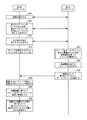
FIG. 6 illustrates a process for calculating proximity between a first IoT device and a second IoT device according to an embodiment of the present invention. In FIG. 6, the first IoT device and the second IoT device establish a connection (600). The connection established at 600 may correspond to a direct connection such as Bluetooth®, or alternatively an indirect connection mediated by a third device (not shown) such as
610において、第1のIoTデバイスと第2のIoTデバイスとの間の近さ(または距離)を計算するための近さ検出手順を実行することが決定される。610の決定は、どちらかのIoTデバイスによって開始され、それから、他方のIoTデバイスに伝えられる可能性がある。したがって、610において、第1のIoTデバイスが近さ検出手順を実行すると決定する場合、第1のIoTデバイスは、手順を開始するための命令を600からの接続を介して第2のIoTデバイスに送信し得る。同様に、600において、第2のIoTデバイスが近さ検出手順を実行すると決定する場合、第2のIoTデバイスは、手順を開始するための命令を600からの接続を介して第1のIoTデバイスに送信し得る。 At 610, it is determined to perform a proximity detection procedure to calculate a proximity (or distance) between the first IoT device and the second IoT device. 610 decisions may be initiated by one IoT device and then communicated to the other IoT device. Thus, if at 610 it is determined that the first IoT device performs the proximity detection procedure, the first IoT device sends an instruction to initiate the procedure to the second IoT device via the connection from 600. Can be sent. Similarly, if at 600, the second IoT device decides to perform a proximity detection procedure, the second IoT device will issue an instruction to initiate the procedure via the connection from 600 to the first IoT device. Can be sent to.
近さ検出手順を実行する決定の後、第1のIoTデバイスが、第2のIoTデバイスからの「チャープ」を監視するためにその第1のIoTデバイスのマイクロホンをオンにする(615)。第1のIoTデバイスにその第1のIoTデバイスのマイクロホンを設定するための時間を与えるための任意の遅延期間の後、第2のIoTデバイスが、第1の通信経路(たとえば、音声伝播媒体)上でチャープを出力し(620)、さらに、第2の通信経路(たとえば、Bluetooth(登録商標)もしくは見通し(LoS: line-of-sight)発光シーケンスなどの直接通信、またはアクセスポイントを介したIP接続などの間接通信経路)上で第1のIoTデバイスにチャープに関連するデータパケットを送信する(625)。 After the decision to perform the proximity detection procedure, the first IoT device turns on the microphone of the first IoT device to monitor “chirp” from the second IoT device (615). After any delay period to give the first IoT device time to set up the microphone of that first IoT device, the second IoT device is connected to the first communication path (e.g., audio propagation medium) The chirp is output above (620), and the second communication path (for example, Bluetooth (registered trademark) or direct communication such as line-of-sight (LoS) emission sequence) or IP via an access point A data packet related to the chirp is transmitted to the first IoT device on an indirect communication path such as connection (625).
図6の620を参照すると、第1の例において、チャープは、第1のIoTデバイスと第2のIoTデバイスとの間のネゴシエーションを必要としない予め決められたまたは予め構成された音声シグネチャに対応する可能性がある。たとえば、第1のIoTデバイスがスマートフォンであり、第2のIoTデバイスが電子レンジである例においては、電子レンジが、近さ検出手順のために使用する特別な種類のビープを用いて予め構成される可能性があり、スマートフォンが、電子レンジによって使用されるビープを知っている可能性があり、したがって、その種のチャープが、近さ検出手順中に第1のIoTデバイスと第2のIoTデバイスとの間でネゴシエーションされる必要がない。代替的に、第2の例において、チャープは、動的にネゴシエーションされる可能性がある(たとえば、第2のIoTデバイスがその第2のIoTデバイスの利用可能なチャープのリストを提供する可能性があり、第1のIoTデバイスがチャープのうちの1つを承認または選択する可能性があり、第1のIoTデバイスが特定のチャープを要求する可能性があり、利用可能である場合、第2のIoTデバイスがそのチャープを使用するなど)。さらに、チャープ自体は、第2のIoTデバイスの音声出力能力に応じて単純であるかまたは複雑である可能性がある。たとえば、上述のように、チャープは、第2のIoTデバイスが電子レンジなどの単純な機具である場合、単純なビープに対応する可能性があり、または代替的に、チャープは、第2のIoTデバイスがより洗練されたスピーカにアクセスすることができる場合、複雑な波形である可能性がある。また、第1のIoTデバイスおよび第2のIoTデバイスの近傍の任意のユーザに配慮するために、チャープは、チャープが人間の耳に検出され得ないように(たとえば、人が聞くことに関連する閾値未満の)超低周波数または(たとえば、人が聞くことに関連する閾値を超える)超音波周波数で変調される可能性がある。さらに別の例において、チャープは、第1のIoTデバイスのマイクロホンによって十分に検出され得ないチャープが避けられる一方、第1のIoTデバイスのマイクロホンによって十分に検出され得ると予測されるチャープが出力のために選択される(たとえば、第1のIoTデバイスのマイクロホンに関する検出範囲外であると分かっているチャープ周波数が近さ検出手順中に使用から除外されるなど)ように、部分的に、マイクロホンの品質に基づいて規制される可能性がある。 Referring to 620 in FIG. 6, in the first example, the chirp corresponds to a predetermined or pre-configured voice signature that does not require negotiation between the first IoT device and the second IoT device. there's a possibility that. For example, in an example where the first IoT device is a smartphone and the second IoT device is a microwave oven, the microwave oven is preconfigured with a special type of beep that is used for proximity detection procedures. And the smartphone may know the beep used by the microwave oven, so that type of chirp is the first IoT device and the second IoT device during the proximity detection procedure. There is no need to negotiate with Alternatively, in the second example, the chirp may be negotiated dynamically (e.g., the second IoT device may provide a list of available chirps for that second IoT device) If the first IoT device may approve or select one of the chirps and the first IoT device may require a specific chirp and is available, then the second IoT devices use that chirp). Furthermore, the chirp itself can be simple or complex depending on the audio output capability of the second IoT device. For example, as described above, a chirp may correspond to a simple beep if the second IoT device is a simple instrument such as a microwave oven, or alternatively, the chirp is a second IoT If the device can access a more sophisticated speaker, it can be a complex waveform. Also, to account for any user in the vicinity of the first IoT device and the second IoT device, the chirp should prevent the chirp from being detected in the human ear (e.g. related to human hearing) It may be modulated at an ultra-low frequency (below a threshold) or an ultrasound frequency (eg, above a threshold associated with human hearing). In yet another example, a chirp avoids a chirp that cannot be sufficiently detected by the microphone of the first IoT device, while a chirp that is expected to be sufficiently detected by the microphone of the first IoT device is output. Part of the microphone so that it is selected (e.g., a chirp frequency known to be outside the detection range for the microphone of the first IoT device is excluded from use during the proximity detection procedure). May be regulated based on quality.
図6の625を参照すると、データパケットが、600において確立された接続または代替的に異なる接続を介して配信される可能性がある。図6の実施形態においては、データパケットが非常に少ないレイテンシで配信されると仮定される。たとえば、データパケットは、Bluetooth(登録商標)接続を介して、ローカルWiFi接続を介して、または第2のIoTデバイスから第1のIoTデバイスへの見通し(LoS)発光のシーケンスとして配信される可能性がある。どのようにしてデータパケットが第2のIoTデバイスから第1のIoTデバイスに配信されるかに関わりなく、チャープおよびデータパケットは、620および625において、第2のIoTデバイスによるそれらの各々の送信を実質的に同時に開始する(たとえば、チャープは、データパケットが第2のIoTデバイスを離れた後の短い期間再生され続ける可能性があるが、それらの送信の開始時間は、実質的に同じである)。本明細書において使用されるとき、「実質的に同時」に始まるチャープおよびデータパケットは、第1のIoTデバイスと第2のIoTデバイスとの間のチャープの予測される音の伝播遅延がそれぞれの送信開始時間の間のいずれの差に対しても多いと予測されることを意味する。これは、チャープの音の伝播遅延が第1のデバイスと第2のデバイスとの間の距離を概算するために使用され得ることを保証するためである。たとえば、「実質的に同時」は、一例においては、IoT環境自体のサイズに依存する特定のレベルの精度に関連する可能性がある(たとえば、小さなIoT環境に関しては15ミリ秒以内、大きなIoT環境に関しては2ミリ秒以内など)。 Referring to 625 of FIG. 6, data packets may be delivered over the connection established at 600 or alternatively a different connection. In the embodiment of FIG. 6, it is assumed that the data packet is delivered with very little latency. For example, data packets can be delivered via a Bluetooth connection, via a local WiFi connection, or as a sequence of line-of-sight (LoS) emission from a second IoT device to a first IoT device There is. Regardless of how the data packets are delivered from the second IoT device to the first IoT device, the chirp and data packets receive their respective transmissions by the second IoT device at 620 and 625. Start at substantially the same time (e.g., chirps may continue to play for a short period of time after the data packet leaves the second IoT device, but their transmission start times are substantially the same ). As used herein, chirps and data packets that begin “substantially simultaneously” have a chirp's expected sound propagation delay between the first IoT device and the second IoT device, respectively. It means that it is predicted to be large for any difference between the transmission start times. This is to ensure that the propagation delay of the chirp sound can be used to approximate the distance between the first device and the second device. For example, “substantially simultaneous” may in one example relate to a certain level of accuracy that depends on the size of the IoT environment itself (for example, within 15 milliseconds for small IoT environments, large IoT environments For example, within 2 milliseconds).
第1のIoTデバイスが、時間t1においてチャープを検出し、時間t2においてデータパケットを検出する(630)。そして、第1のIoTデバイスが、時間t1と時間t2との間の差に基づいて第2のIoTデバイスに対するその第1のIoTデバイスの近さを計算する(635)。たとえば、概して、音は、1フィート毎ミリ秒(ms)で進む。したがって、データパケットが非常に少ない伝播レイテンシを被ったという仮定の下で、t1とt2との間のミリ秒数が、フィートで表された第1のIoTデバイスと第2のIoTデバイスとの間の距離に関する推定値として使用され得る。たとえば、時間t1が7:03:05.003であり、時間t2が7:03:05.006である場合、第1のIoTデバイスおよび第2のIoTデバイスは、互いにおよそ3フィート離れているものとして推定され得る。音がその音の伝播速度を大きく落とすことなく壁およびその他の障害物を通り抜けることは、さらに理解されるであろう。その結果、上述の計算は、介在する障害物に無関係に2つのIoTデバイスの間の絶対的な距離(または近さ)の推定に役立ち得る。630の検出に関連して、第1のIoTデバイスは、(たとえば、時間t1およびt2が、互いに数ミリ秒離れているなど比較的互いに近いことに基づいて)チャープおよびデータパケットが近さ検出手順に関連付けられることを第1のIoTデバイスが知るようにチャープをデータパケットと相互に関連付ける。 The first IoT device detects chirp at time t1 and detects a data packet at time t2 (630). The first IoT device then calculates the proximity of the first IoT device to the second IoT device based on the difference between time t1 and time t2 (635). For example, generally, sound travels in 1 foot per millisecond (ms). Therefore, under the assumption that the data packet suffered very little propagation latency, the number of milliseconds between t1 and t2 is between the first IoT device and the second IoT device expressed in feet. Can be used as an estimate for the distance. For example, if time t1 is 7: 03: 05.003 and time t2 is 7: 03: 05.006, the first IoT device and the second IoT device may be estimated as being approximately 3 feet away from each other . It will be further understood that sound passes through walls and other obstacles without significantly reducing the speed of sound propagation. As a result, the above calculations can help estimate the absolute distance (or proximity) between two IoT devices regardless of the intervening obstacles. In connection with the detection of 630, the first IoT device can detect the proximity of chirp and data packets (e.g., based on times t1 and t2 being relatively close to each other, such as several milliseconds apart). Correlate the chirp with the data packet so that the first IoT device knows that it will be associated with.
図6が、第1のIoTデバイスがチャープの検出をデータパケットの受信と正しく関連付ける(または相互に関連付ける)ことができること、およびデータパケットに関する無視できる量の伝播レイテンシが存在することなどの特定の仮定に基づいて簡略化される実施形態を示すことは、理解されるであろう。図7は、第1のIoTデバイスと第2のIoTデバイスとの間の近さを計算するプロセスを対象とし、本発明の実施形態によれば、そのプロセスによって、閾値の量のネットワーク伝播遅延が存在し、第1のIoTデバイスにおいてチャープをデータパケットと相互に関連付けるのを助けるためにデータパケットによって相関情報が提供される。 Figure 6 shows certain assumptions such as the ability of the first IoT device to correctly correlate (or correlate) the detection of chirp with the reception of data packets, and that there is a negligible amount of propagation latency for data packets. It will be understood that a simplified embodiment based on the above is shown. FIG. 7 is directed to the process of calculating the proximity between the first IoT device and the second IoT device, and according to an embodiment of the invention, the process results in a threshold amount of network propagation delay. Corresponding information is provided by the data packet to help correlate the chirp with the data packet in the first IoT device.
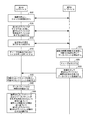
図7を参照すると、700から715までは、実質的に、図6の600から615までに対応する。しかし、図7においては、700において確立される接続が、インターネット175によって仲介されると仮定され、インターネット175による仲介は、第1のIoTデバイスと第2のIoTデバイスとの間で接続を介してやりとりされる任意のデータパケットに対して特定の量のネットワーク伝播レイテンシを引き起こす。
Referring to FIG. 7, 700 to 715 substantially correspond to 600 to 615 in FIG. However, in FIG. 7, it is assumed that the connection established at 700 is mediated by the
図7を参照すると、720において、第2のIoTデバイスが、第2のIoTデバイスによって出力されるチャープをデータパケットと相互に関連付けるための相関情報を含むようにデータパケットを構成する。図6においては、第2のIoTデバイスによって出力されるチャープの種類が、第1のIoTデバイスがチャープを適切に検出し、検出されたチャープを到着するデータパケットと関連付けることができるようにするために第1のIoTデバイスに知られている必要があった。しかし、図7においては、第1のIoTデバイスが必ずしも近さ検出手順の前にいかなるチャープの特性も知っている必要がないように、データパケット自体が、第1のIoTデバイスがチャープを特定することを可能にするのに十分な情報を含む可能性がある。一例において、データパケットに含まれる相関情報は、チャープを特徴付けるデュアルトーン多周波数(DTMF: dual-tone multi-frequency)シグネチャを含む可能性がある。別の例において、データパケットに含まれる相関情報は、チャープを特徴付けるパルス符号変調(PCM)シグネチャを含む可能性がある。 Referring to FIG. 7, at 720, the second IoT device configures the data packet to include correlation information for correlating the chirp output by the second IoT device with the data packet. In FIG. 6, the type of chirp output by the second IoT device allows the first IoT device to properly detect the chirp and associate the detected chirp with the incoming data packet. The first IoT device needed to be known. However, in Figure 7, the data packet itself identifies the chirp so that the first IoT device does not necessarily need to know any chirp characteristics prior to the proximity detection procedure. It may contain enough information to make it possible. In one example, the correlation information included in the data packet may include a dual-tone multi-frequency (DTMF) signature that characterizes the chirp. In another example, the correlation information included in the data packet may include a pulse code modulation (PCM) signature that characterizes the chirp.
720において相関情報を用いてデータパケットを構成した後、および第1のIoTデバイスにその第1のIoTデバイスのマイクロホンを設定するための時間を与えるための任意の遅延期間の後、第2のIoTデバイスが、チャープを出力し、さらに、構成されたデータパケットを第1のIoTデバイスに実質的に同時に送信する(725および730)(たとえば、チャープは、データパケットが第2のIoTデバイスを離れた後の短い期間再生され続ける可能性があるが、それらの送信の開始時間は、実質的に同じである)。一実施形態において、第2のIoTデバイスは、データパケットの配信のために使用するために、1組の利用可能な転送メカニズムから最も低い予測されるネットワーク伝播レイテンシを有する転送メカニズムを選択する可能性がある。たとえば、第1のIoTデバイスおよび第2のIoTデバイスがインターネット175を通じたIP接続によって接続される場合、第2のIoTデバイスは、ユーザデータグラムプロトコル(UDP)がレイテンシのより低い転送プロトコルであるので伝送制御プロトコル(TCP)の代わりにUDPを選択する可能性がある。もちろん、その他の筋書きではデータパケットの配信のために引き続きTCPが使用される可能性がある。また、Bluetooth(登録商標)などの直接接続が利用可能であるとすれば、直接接続のより低い予測される伝播レイテンシが原因で、直接接続が選択されることになる。
After configuring the data packet with correlation information at 720, and after any delay period to give the first IoT device time to set up the microphone of that first IoT device, the second IoT The device outputs a chirp and further sends the configured data packet to the first IoT device substantially simultaneously (725 and 730) (e.g., the chirp leaves the second IoT device They may continue to play for a short period of time later, but their transmission start time is substantially the same). In one embodiment, the second IoT device may select a transport mechanism with the lowest expected network propagation latency from a set of available transport mechanisms to use for delivery of data packets. There is. For example, if the first IoT device and the second IoT device are connected by an IP connection over the
第1のIoTデバイスは、時間t1においてチャープを検出し、時間t2においてデータパケットを検出する(735)(たとえば、図6の630と同様)。図7の実施形態において、第1のIoTデバイスは、さらに、チャープをデータパケットと相互に関連付けるのを助けるために、受信されたデータパケットから相関情報を抽出する(740)。たとえば、相関情報がPCMまたはDTMFシグネチャを含む場合、第1のIoTデバイスは、PCMまたはDTMFシグネチャをその第1のIoTデバイスの捕捉された音声データと比較して、735においてチャープが検出された時を正確に特定することができる。 The first IoT device detects chirp at time t1 and detects a data packet at time t2 (735) (eg, similar to 630 in FIG. 6). In the embodiment of FIG. 7, the first IoT device further extracts 740 correlation information from the received data packet to help correlate the chirp with the data packet. For example, if the correlation information includes a PCM or DTMF signature, the first IoT device compares the PCM or DTMF signature with the captured voice data of that first IoT device and when a chirp is detected at 735 Can be accurately identified.
745において、時間t2をデータパケットの検出時間として修正なしに使用する代わりに、第1のIoTデバイスが、ネットワーク伝播レイテンシの推定に基づいて時間t2を調整して、調整された検出時間t2'を生成する。一例において、ネットワーク伝播レイテンシの推定は、第1のIoTデバイスと第2のIoTデバイスとの間で別のデータパケットを送信して往復遅延(RTD)を決定することまたはその他のレイテンシ推定メカニズムなどの任意の数の方法で実施され得る。1つの特定のネットワーク伝播レイテンシ推定メカニズムが、図10に関連して以下でより詳細に説明される。そして、第1のIoTデバイスが、(図6の635の時間t1と時間t2との間の差の代わりに)時間t1と時間t2'との間の差に基づいて第2のIoTデバイスに対するその第1のIoTデバイスの近さを計算する(750)。 At 745, instead of using time t2 as the detection time for the data packet without modification, the first IoT device adjusts time t2 based on an estimate of network propagation latency and uses the adjusted detection time t2 ′. Generate. In one example, network propagation latency estimation may involve sending another data packet between the first IoT device and the second IoT device to determine round trip delay (RTD) or other latency estimation mechanism, etc. It can be implemented in any number of ways. One particular network propagation latency estimation mechanism is described in more detail below with respect to FIG. Then, the first IoT device will determine that the second IoT device is based on the difference between time t1 and time t2 ′ (instead of the difference between time t1 and time t2 at 635 in FIG. 6). Calculate the proximity of the first IoT device (750).
図7は、相関情報がデータパケット内に埋め込まれる実施形態を示すが、代わりに、相関情報がチャープ内に埋め込まれる可能性があることもあり得る。したがって、図7のデータパケット内の相関情報は、第1のIoTデバイスがチャープを特定し、チャープをデータパケットと関連付けるのを助けるが、図8のチャープ内の相関情報は、第1のIoTデバイスがデータパケットを特定し、データパケットをチャープと関連付けるのを助ける。 Although FIG. 7 illustrates an embodiment in which correlation information is embedded in a data packet, it is possible that correlation information may instead be embedded in a chirp. Thus, the correlation information in the data packet of FIG. 7 helps the first IoT device identify the chirp and associate the chirp with the data packet, while the correlation information in the chirp of FIG. Helps identify data packets and associate data packets with chirps.
図8は、第1のIoTデバイスと第2のIoTデバイスとの間の近さを計算するプロセスを対象とし、本発明の実施形態によれば、そのプロセスによって、皆無かそれに近いネットワーク伝播遅延しか存在せず、第1のIoTデバイスにおいてチャープをデータパケットと相互に関連付けるのを助けるためにチャープによって相関情報が提供される。 FIG. 8 is directed to the process of calculating the proximity between the first IoT device and the second IoT device, and according to an embodiment of the present invention, the process results in little or no network propagation delay. Not present and correlation information is provided by the chirp to help correlate the chirp with the data packet in the first IoT device.
図8を参照すると、800から815までは、実質的に、図6の600から615までに対応する。820において、第2のIoTデバイスが、第2のIoTデバイスによって出力されるデータパケットをチャープと相互に関連付けるための相関情報を含むようにチャープを構成する。図6においては、第2のIoTデバイスによって出力されるチャープの種類が、第1のIoTデバイスがチャープを適切に検出し、検出されたチャープを到着するデータパケットと関連付けることができるようにするために第1のIoTデバイスに知られている必要がある。しかし、図8においては、チャープ自体が、第1のIoTデバイスが対応するデータパケットを特定することを可能にするのに十分な情報を含む可能性がある。一例において、チャープに含まれる相関情報は、音声信号上に情報を重ねて合成するためのウォーターマークの特徴またはその他のメカニズムによって埋め込まれる可能性がある。さらなる例においては、第1のIoTデバイスがチャープからのシーケンス番号をデータパケットのヘッダ内のシーケンス番号と比較して、近さ検出手順に関連して受信されるデータパケットを検証することができるように、相関情報が、対応するデータパケットのシーケンス番号を含む可能性がある。 Referring to FIG. 8, 800 to 815 substantially corresponds to 600 to 615 in FIG. At 820, the second IoT device configures the chirp to include correlation information for correlating data packets output by the second IoT device with the chirp. In FIG. 6, the type of chirp output by the second IoT device allows the first IoT device to properly detect the chirp and associate the detected chirp with the incoming data packet. It must be known to the first IoT device. However, in FIG. 8, the chirp itself may contain sufficient information to allow the first IoT device to identify the corresponding data packet. In one example, the correlation information contained in the chirp may be embedded by watermark features or other mechanisms for overlaying and synthesizing information on the audio signal. In a further example, the first IoT device can compare the sequence number from the chirp with the sequence number in the header of the data packet to verify the data packet received in connection with the proximity detection procedure. In addition, the correlation information may include the sequence number of the corresponding data packet.
820において相関情報を用いてチャープを構成した後、および第1のIoTデバイスにその第1のIoTデバイスのマイクロホンを設定するための時間を与えるための任意の遅延期間の後、第2のIoTデバイスは、構成されたチャープを出力し、さらに、データパケットを第1のIoTデバイスに実質的に同時に送信する(825および830)(たとえば、チャープは、データパケットが第2のIoTデバイスを離れた後の短い期間再生され続ける可能性があるが、それらの送信の開始時間は、実質的に同じである)。図8の実施形態において、データパケットは、たとえば、直接Bluetooth(登録商標)接続、光信号のシーケンスなどによって、皆無かそれに近いレイテンシ(たとえば、1または2ミリ秒以下など)で配信されると仮定される。 After configuring the chirp with the correlation information at 820 and after any delay period to give the first IoT device time to set up the microphone for that first IoT device, the second IoT device Outputs the configured chirp and further transmits the data packet to the first IoT device substantially simultaneously (825 and 830) (e.g., after the data packet leaves the second IoT device) But their transmission start time is substantially the same). In the embodiment of FIG. 8, it is assumed that data packets are delivered with little or no latency (eg, 1 or 2 milliseconds or less), eg, via a direct Bluetooth connection, a sequence of optical signals, etc. Is done.
第1のIoTデバイスは、時間t1においてチャープを検出し、時間t2においてデータパケットを検出する(835)(たとえば、図6の630と同様)。図8の実施形態において、第1のIoTデバイスは、さらに、チャープをデータパケットと相互に関連付けるのを助けるために、検出されたチャープから相関情報を抽出する(840)。たとえば、相関情報がシーケンス番号を含む場合、第1のIoTデバイスは、チャープのシグネチャからのシーケンス番号をデータパケットのヘッダからのシーケンス番号と比較して、その特定のデータパケットがチャープに関連するデータパケットであることを近さ検出手順に関連して検証することができる。そして、第1のIoTデバイスが、(たとえば、図6の635と同様に)時間t1と時間t2との間の差に基づいて第2のIoTデバイスに対するその第1のIoTデバイスの近さを計算する(845)。 The first IoT device detects chirp at time t1 and detects a data packet at time t2 (835) (eg, similar to 630 in FIG. 6). In the embodiment of FIG. 8, the first IoT device further extracts correlation information from the detected chirp to help correlate the chirp with the data packet (840). For example, if the correlation information includes a sequence number, the first IoT device compares the sequence number from the chirp signature with the sequence number from the data packet header, and the data that that particular data packet is associated with the chirp The packet can be verified in relation to the proximity detection procedure. The first IoT device then calculates the proximity of that first IoT device to the second IoT device based on the difference between time t1 and time t2 (for example, as in 635 in FIG. 6) (845).
図7〜図8は、相関情報がデータパケット(たとえば、図7)かまたはチャープ(たとえば、図8)かのどちらかに含まれる例を示すが、相関情報は、データパケットとチャープとの両方に含まれることもあり得る。このようにして、最初にチャープが検出される場合、チャープ内の相関情報は、データパケットを検出するのを助けるために使用される可能性があり、最初にデータパケットが検出される場合、データパケット内の相関情報は、チャープを検出するのを助けるために使用される可能性がある。 FIGS. 7-8 show examples where correlation information is included in either a data packet (e.g., FIG. 7) or a chirp (e.g., FIG. 8), but the correlation information includes both the data packet and the chirp May be included. In this way, if chirp is first detected, the correlation information in the chirp may be used to help detect the data packet, and if the data packet is first detected, the data The correlation information in the packet may be used to help detect chirp.
図6から図8に関連して上で説明された実施形態は、クロックの同期が第1のIoTデバイスと第2のIoTデバイスとの間で可能かどうかに関わりなく実装のために構成される。たとえば、IoTコーヒーメーカーデバイスのクロックは、通常、近くのIoTスマートフォンデバイスとまったく同期されておらず、ましてや、ミリ秒レベルの精度では同期されていない。しかし、一部の筋書きでは、一部のIoTデバイスがそれらのデバイスのクロックを互いに同期させる可能性がある。このことを念頭に置いて、図9は、特に、このレベルの精度でクロックの同期が存在する実装を対象とする。より詳細には、図9は、本発明の実施形態による、第1のIoTデバイスと第2のIoTデバイスとの間のクロックの同期が存在する場合の第1のIoTデバイスと第2のIoTデバイスとの間の近さを計算するプロセスを対象とする。図9においては、以下でより詳細に説明されるように、クロックの同期のおかげで、データパケットに関する配信メカニズムに関連するネットワーク伝播レイテンシは無関係である。 The embodiments described above in connection with FIGS. 6-8 are configured for implementation regardless of whether clock synchronization is possible between the first IoT device and the second IoT device. . For example, the clock of an IoT coffee maker device is usually not synchronized at all with a nearby IoT smartphone device, and even better, with millisecond accuracy. However, in some scenarios, some IoT devices may synchronize their clocks with each other. With this in mind, FIG. 9 is specifically directed to implementations where clock synchronization exists with this level of accuracy. More specifically, FIG. 9 illustrates a first IoT device and a second IoT device when there is clock synchronization between the first IoT device and the second IoT device, according to an embodiment of the present invention. For the process of calculating the closeness between. In FIG. 9, as explained in more detail below, thanks to clock synchronization, the network propagation latency associated with the delivery mechanism for data packets is irrelevant.
図9を参照すると、900から915までは、実質的に、図6の600から615までに対応する。920において、第1のIoTデバイスにその第1のIoTデバイスのマイクロホンを設定するための時間を与えるための任意の遅延期間の後、第2のIoTデバイスが、少なくとも数ミリ秒以内の正確さの精度のレベルで、「時間tX」と呼ばれる現在の時間、たとえば、9:36:04.001を含むようにデータパケットを構成する。精度のレベルは、第1のIoTデバイスと第2のIoTデバイスとの間のクロックの同期が正確である度合いに基づく可能性がある(たとえば、2つのクロックが2ミリ秒以内の誤差で同期される場合、時間tXは、2ミリ秒以内の正確さである可能性があるなど)。 Referring to FIG. 9, 900 to 915 substantially correspond to 600 to 615 in FIG. At 920, after any delay period to give the first IoT device time to set up the microphone of that first IoT device, the second IoT device is accurate to within at least a few milliseconds. At a level of accuracy, the data packet is configured to include a current time, called “time tX”, for example, 9: 36: 04.001. The level of accuracy may be based on the degree to which the clock synchronization between the first IoT device and the second IoT device is accurate (for example, the two clocks are synchronized with an error within 2 milliseconds). The time tX may be accurate to within 2 milliseconds).
920において時間tXを用いてデータパケットを構成した後、第2のIoTデバイスは、実質的に時間tXにおいてチャープを出力し(925)、さらに、構成されたデータパケットを第1のIoTデバイスに送信する(930)。図6〜図8とは異なり、チャープおよびデータパケットに関する送信開始時間は、データパケットが時間tXの指示を含むので、図9においては必ずしも揃えられる必要がない。言い換えれば、第1のIoTデバイスは、tXをチャープの推定された送信開始点として使用し、したがって、たとえデータパケット自体が厳密に時間tXに送信されないとしても、時間tXは、チャープの音の伝播速度に基づいて第1のIoTデバイスと第2のIoTデバイスとの間の距離を概算するためにやはり有用である。 After composing the data packet with time tX at 920, the second IoT device effectively outputs a chirp at time tX (925) and further transmits the configured data packet to the first IoT device. (930). Unlike FIGS. 6-8, the transmission start times for chirps and data packets do not necessarily have to be aligned in FIG. 9, since the data packets include an indication of time tX. In other words, the first IoT device uses tX as the chirp's estimated transmission start point, so time tX is the propagation of the chirp sound, even if the data packet itself is not strictly transmitted at time tX. It is also useful to approximate the distance between the first IoT device and the second IoT device based on speed.
第1のIoTデバイスは、時間t1においてチャープを検出し(935)、時間t2においてデータパケットを検出する(940)(たとえば、図6の630と同様)。図9の実施形態において、第1のIoTデバイスは、さらに、受信されたデータパケットからtXを抽出する(940)。そして、第1のIoTデバイスが、(図6の635の時間t1と時間t2との間の差の代わりに)時間t1と時間tXとの間の差に基づいて第2のIoTデバイスに対するその第1のIoTデバイスの近さを計算する(945)。理解されるように、時間t1と時間tXとの間の時間差は、第1のIoTデバイスと第2のIoTデバイスとの間の距離を推測するために使用され得るチャープに関する伝播時間に実質的に等しい。 The first IoT device detects a chirp at time t1 (935) and detects a data packet at time t2 (940) (eg, similar to 630 in FIG. 6). In the embodiment of FIG. 9, the first IoT device further extracts tX from the received data packet (940). Then, the first IoT device is connected to the second IoT device based on the difference between time t1 and time tX (instead of the difference between time t1 and time t2 at 635 in FIG. 6). Calculate the proximity of 1 IoT device (945). As will be appreciated, the time difference between time t1 and time tX is substantially in the propagation time for the chirp that can be used to infer the distance between the first IoT device and the second IoT device. equal.
図9の代替として、データパケットの代わりに、チャープ自体が、時間tXを埋め込まれる可能性がある。この場合、データパケットは、完全に省略される可能性があり、第1のIoTデバイスは、チャープの受信時間t1とチャープ内で示される時間tXとの間の差にのみ基づいて第1のIoTデバイスと第2のIoTデバイスとの間の近さを計算する可能性がある。 As an alternative to FIG. 9, instead of a data packet, the chirp itself may be embedded with time tX. In this case, the data packet may be omitted altogether, and the first IoT device will only use the first IoT based on the difference between the chirp reception time t1 and the time tX indicated in the chirp. May calculate the proximity between the device and the second IoT device.
図10は、第1のIoTデバイスと第2のIoTデバイスとの間の近さを計算するプロセスを対象とし、本発明の実施形態によれば、そのプロセスによって、閾値の量のネットワーク伝播遅延が存在し、クロックの同期が利用不可能である。 FIG. 10 is directed to the process of calculating the proximity between the first IoT device and the second IoT device, and according to an embodiment of the invention, the process results in a network propagation delay of a threshold amount. Exists and clock synchronization is not available.
図10を参照すると、1000から1005までは、実質的に、図6の600から605までに対応する。しかし、図10においては、1000において確立される接続が、インターネット175によって仲介されると仮定され、インターネット175による仲介は、第1のIoTデバイスと第2のIoTデバイスとの間で接続を介してやりとりされる任意のデータパケットに対して特定の量のネットワーク伝播レイテンシを引き起こす。さらに、ネットワーク伝播レイテンシが第1のIoTデバイスに既に知られていると仮定された図7とは異なり、図10は、レイテンシ発見方式によってネットワーク伝播レイテンシを動的に計算することを対象とする。
Referring to FIG. 10, 1000 to 1005 substantially corresponds to 600 to 605 in FIG. However, in FIG. 10, it is assumed that the connection established at 1000 is mediated by the
図10を参照すると、1010において、(図6〜図9のチャープおよびデータパケットの1回の送信とは対照的に)決まった送信スケジュールに従って近さ検出手順を実施すると決定される。1015において、第1のIoTデバイスが、その第1のIoTデバイスのマイクロホンをオンにする。そして、第1のIoTデバイスと第2のIoTデバイスとの両方が決まった送信スケジュールを知らされると、第2のIoTデバイスが、決まった送信スケジュールによって定義された間隔で、チャープのシーケンスを対応するデータパケットとともに送信し始める。 Referring to FIG. 10, at 1010, it is determined to perform the proximity detection procedure according to a fixed transmission schedule (as opposed to a single transmission of the chirp and data packets of FIGS. 6-9). At 1015, the first IoT device turns on the microphone of the first IoT device. And when both the first IoT device and the second IoT device are informed of the fixed transmission schedule, the second IoT device supports the chirp sequence at intervals defined by the fixed transmission schedule Start transmitting with the data packet to be sent.
したがって、第2のIoTデバイスは、決まった送信スケジュールによって定義された第1の送信時間(「送信時間1」)において第1のチャープ(「チャープ1」)を出力し、第1のデータパケット(「データパケット1」)を送信する(1020および1025)。第1のIoTデバイスは、時間tC1においてチャープ1を検出し、時間tP2においてデータパケット1を検出する(1030)。次に、第2のIoTデバイスは、決まった送信スケジュールによって定義された送信時間2...N-1においてチャープ2...N-1をそれぞれのデータパケット2...N-1と一緒に出力する(1035および1040)。第1のIoTデバイスは、時間tC2...tCN-1においてチャープ2...N-1をそれぞれ検出し、時間tP2...tPN-1においてデータパケット2...N-1をそれぞれ検出する(1045)。ネットワーク伝播レイテンシが比較的一定であるという仮定の下で、第1のIoTデバイスは、データパケットのうちの1つの到着時間と次のチャープの到着時間との間の差の平均としてネットワーク伝播レイテンシを計算することができる。したがって、tP1とtC2との間の差、tP2とtC3との間の差、...、tPN-2とtCN-1との間の差が計算され、それから、ネットワーク伝播レイテンシを推定するためにまとめて平均され得る(1050)。1050においてネットワーク伝播レイテンシを推定した後、1055から1075までは、第1のIoTデバイスにそれぞれ時間tCNおよびtPNに到着するチャープNおよびデータパケットNの後続の送信に関して725から750までに実質的に対応し、それによって、tPNは、(たとえば、tPN'とtCNとの間の距離に基づいて)近さを計算するために使用されるtPN'を生成するために、推定されたネットワーク伝播レイテンシに基づいて調整される。
Therefore, the second IoT device outputs the first chirp (`` chirp 1 '') at the first transmission time (`` transmission time 1 '') defined by the fixed transmission schedule, and the first data packet ( "
図6〜図10の実施形態は、2つのIoTデバイスが互いに対するそれらのIoTデバイスの近さを決定することに関するが、マイクロホンを有する複数のIoTデバイスが(たとえば、図11に関連して以下で説明されるように)単一の近さ検出手順によって「チャープを発する」IoTデバイスに対するそれらのIoTデバイスの位置を計算することができる実装と、さらに、マイクロホンを有する単一のIoTデバイスが(たとえば、図12に関連して以下で説明されるように)三辺測量によって複数のその他のチャープを発するデバイスに対するそのIoTデバイスの相対的位置を計算することができる実装とにこれらの教示を拡張することが可能である。 While the embodiments of FIGS. 6-10 relate to two IoT devices determining their proximity to each other, multiple IoT devices with microphones (e.g., below in connection with FIG. An implementation that can calculate the position of those IoT devices relative to a `` chirping '' IoT device with a single proximity detection procedure (as described), and also a single IoT device with a microphone (e.g. Extend these teachings to implementations that can calculate the relative position of that IoT device relative to devices that emit multiple other chirps by trilateration (as described below in connection with FIG. 12) It is possible.
図11を参照すると、第1の、第2の、および第3のIoTデバイスが、互いに接続を確立する(1100)。1100において確立される接続は、同じであるかまたは異なる可能性がある。たとえば、第1のIoTデバイスが、第1のBluetooth(登録商標)接続によって第2のIoTデバイスに接続される可能性があり、第2のBluetooth(登録商標)接続によって第3のIoTデバイスに接続される可能性がある。別の例においては、第1のIoTデバイスが、アクセスポイント125を介して第2のIoTデバイスに接続される可能性があり、第2のIoTデバイスが、Bluetooth(登録商標)接続によって第3のIoTデバイスに接続される可能性がある。別の例においては、第1のIoTデバイスが、Bluetooth(登録商標)接続によって第2のIoTデバイスに接続される可能性があり、第1のIoTデバイスおよび第3のIoTデバイスが直接接続されないように第2のIoTデバイスへのホップによって第3のIoTデバイスに接続される可能性がある。
Referring to FIG. 11, the first, second, and third IoT devices establish a connection with each other (1100). The connections established at 1100 can be the same or different. For example, a first IoT device may be connected to a second IoT device via a first Bluetooth® connection and connected to a third IoT device via a second Bluetooth® connection There is a possibility that. In another example, the first IoT device may be connected to the second IoT device via the
1105において、第1のIoTデバイスおよび第3のIoTデバイスがマイクロホンをプロビジョニングされており、第2のIoTデバイスが音声出力デバイスをプロビジョニングされていると決定される。1105の決定は、図6の605と同様に、第1のIoTデバイスから第3のIoTデバイスまでのいずれか(またはすべて)においてなされ得る。1110において、(i)第1のIoTデバイスと第2のIoTデバイスとの間およびさらに(ii)第2のIoTデバイスと第3のIoTデバイスとの間の近さ(または距離)を計算するための近さ検出手順を実行することが決定される。1110の決定は、図6の610と同様に、第1のIoTデバイスから第3のIoTデバイスまでのいずれかによってなされ得る。 At 1105, it is determined that the first IoT device and the third IoT device have been provisioned with a microphone and the second IoT device has been provisioned with an audio output device. The determination of 1105 can be made anywhere (or all) from the first IoT device to the third IoT device, similar to 605 of FIG. In 1110, to calculate the proximity (or distance) between (i) the first IoT device and the second IoT device and further (ii) the second IoT device and the third IoT device It is determined to perform the proximity detection procedure. The determination of 1110 can be made by any of the first IoT device to the third IoT device, similar to 610 of FIG.
近さ検出手順を実行する決定の後、第1のIoTデバイスおよび第3のIoTデバイスが、第2のIoTデバイスからの「チャープ」を監視するためにそれらのIoTデバイスのマイクロホンをオンにする(1115および1120)。第1のIoTデバイスおよび第3のIoTデバイスにそれらのIoTデバイスの各々のマイクロホンを設定するための時間を与えるための任意の遅延期間の後、第2のIoTデバイスが、チャープを出力し(1125)、さらに、チャープに関連するデータパケットを第1のIoTデバイスと第3のIoTデバイスとの両方に送信する(1130)。したがって、1125は、単一のチャープが第2のIoTデバイスによって出力される限りにおいて図6の620と同様である一方、1130のデータパケットの送信は、2つの別々のデータパケットが第1のIoTデバイスおよび第3のIoTデバイスに送信されるので図6の625とは若干異なる。1130におけるデータパケットの送信は、同じ転送メカニズム(たとえば、UDP、Bluetooth(登録商標)、光シーケンスなど)を介して行われるかまたは異なる転送メカニズムを介して行われるかのどちらかである可能性がある。 After the decision to perform the proximity detection procedure, the first IoT device and the third IoT device turn on the microphones of those IoT devices to monitor “chirp” from the second IoT device ( 1115 and 1120). After any delay period to give the first IoT device and the third IoT device time to set up the microphone for each of those IoT devices, the second IoT device outputs a chirp (1125 In addition, a data packet related to the chirp is transmitted to both the first IoT device and the third IoT device (1130). Thus, 1125 is similar to 620 in FIG. 6 as long as a single chirp is output by the second IoT device, while transmission of 1130 data packets means that two separate data packets are sent to the first IoT Because it is sent to the device and the third IoT device, it is slightly different from 625 in FIG. The transmission of data packets in 1130 can be either via the same transport mechanism (eg, UDP, Bluetooth, optical sequence, etc.) or via a different transport mechanism. is there.
第1のIoTデバイスが、時間t1においてチャープを検出し、時間t2においてそのデータパケットを検出し(1135)(たとえば、図6の630と同様)、第3のIoTデバイスが、時間t3においてチャープを検出し、時間t4においてそのデータパケットを検出する(1140)(たとえば、図6の630と同様)。そして、第1のIoTデバイスが、(たとえば、図6の635と同様に)時間t1と時間t2との間の差に基づいて第2のIoTデバイスに対するその第1のIoTデバイスの近さを計算し(1145)、第3のIoTデバイスも、(たとえば、図6の635と同様に)時間t3と時間t4との間の差に基づいて第2のIoTデバイスに対するその第3のIoTデバイスの近さを計算する(1150)。 The first IoT device detects a chirp at time t1, detects its data packet at time t2 (1135) (e.g., similar to 630 in FIG. 6), and the third IoT device detects a chirp at time t3. Detect and detect the data packet at time t4 (1140) (eg, similar to 630 in FIG. 6). The first IoT device then calculates the proximity of that first IoT device to the second IoT device based on the difference between time t1 and time t2 (for example, as in 635 in FIG. 6) (1145), however, the third IoT device is also the proximity of the third IoT device to the second IoT device based on the difference between time t3 and time t4 (e.g., similar to 635 in FIG. 6). Calculate the length (1150).
図12に目を向けると、第1のIoTデバイスが、第2のIoTデバイス、第3のIoTデバイス、および第4のIoTデバイスとの接続を確立する(1200)。1200において確立される接続は、同じであるかまたは異なる可能性がある。たとえば、第1のIoTデバイスが、第1のBluetooth(登録商標)接続によって第2のIoTデバイスに接続される可能性があり、第2のBluetooth(登録商標)接続によって第3のIoTデバイスに接続される可能性があり、アクセスポイント125を介してインターネット175を通じて第4のIoTデバイスに接続される可能性がある。別の例においては、第1のIoTデバイスが、Bluetooth(登録商標)接続によって第2のIoTデバイスに接続される可能性があり、第1のIoTデバイスが第3のIoTデバイスまたは第4のIoTデバイスに直接接続されないように第2のIoTデバイスへホップすることによって第3のIoTデバイスおよび第4のIoTデバイスに接続される可能性がある。
Turning to FIG. 12, the first IoT device establishes a connection with the second IoT device, the third IoT device, and the fourth IoT device (1200). The connections established at 1200 can be the same or different. For example, a first IoT device may be connected to a second IoT device via a first Bluetooth® connection and connected to a third IoT device via a second Bluetooth® connection And may be connected to the fourth IoT device through the
1205において、第1のIoTデバイスがマイクロホンをプロビジョニングされており、第2のIoTデバイス、第3のIoTデバイス、および第4のIoTデバイスがそれぞれ音声出力デバイスをプロビジョニングされていると決定される。1205の決定は、図6の605と同様に、第1のIoTデバイスから第4のIoTデバイスまでのいずれかにおいてなされ得る。1210において、第1のIoTデバイスと第2のIoTデバイス、第3のIoTデバイス、および第4のIoTデバイスの各々との間の近さ(または距離)を計算するための近さ検出手順を実行することが決定される。1210の決定は、図6の610と同様に、第1のIoTデバイスから第4のIoTデバイスまでのいずれかによってなされ得る。 At 1205, it is determined that the first IoT device has been provisioned with a microphone, and the second IoT device, the third IoT device, and the fourth IoT device are each provisioned with an audio output device. The determination of 1205 can be made anywhere from the first IoT device to the fourth IoT device, similar to 605 in FIG. At 1210, perform a proximity detection procedure to calculate the proximity (or distance) between each of the first IoT device, the second IoT device, the third IoT device, and the fourth IoT device It is decided to do. The determination of 1210 can be made either from the first IoT device to the fourth IoT device, similar to 610 of FIG.
近さ検出手順を実行する決定の後、第1のIoTデバイスが、第2のIoTデバイス、第3のIoTデバイス、および第4のIoTデバイスからの「チャープ」を監視するためにその第1のIoTデバイスのマイクロホンをオンにする(1215)。一例において、第1のIoTデバイスは、時間に基づいて(たとえば、近さ検出手順が、チャープの混同を避けるために逐次的にもしくは連続的に実行される可能性がある)、または代替的に(たとえば、第1のIoTデバイスへのチャープの到着のタイミングがチャープとデバイスとの相関よりも関連性が低いように)第2のIoTデバイス、第3のIoTデバイス、および第4のIoTデバイスの各々から一意のチャープが送信されることによって第2のIoTデバイス、第3のIoTデバイス、および第4のIoTデバイスからのチャープを区別することができる。 After the decision to perform the proximity detection procedure, the first IoT device has its first to monitor the “chirp” from the second IoT device, the third IoT device, and the fourth IoT device. Turn on the microphone of the IoT device (1215). In one example, the first IoT device may be based on time (e.g., proximity detection procedures may be performed sequentially or sequentially to avoid chirp confusion) or alternatively (For example, the timing of arrival of the chirp to the first IoT device is less relevant than the correlation between the chirp and the device) The second IoT device, the third IoT device, and the fourth IoT device A chirp from the second IoT device, the third IoT device, and the fourth IoT device can be distinguished by transmitting a unique chirp from each.
第1のIoTデバイスにその第1のIoTデバイスのマイクロホンを設定するための時間を与えるための任意の遅延期間の後、第2のIoTデバイスが、その第2のIoTデバイスのチャープを出力し(1220)、さらに、その第2のIoTデバイスのチャープに関連するデータパケットを第1のIoTデバイスに送信する(1225)。同様に、第1のIoTデバイスにその第1のIoTデバイスのマイクロホンを設定するための時間を与えるための任意の遅延期間の後、第3のIoTデバイスが、その第3のIoTデバイスのチャープを出力し(1230)、さらに、その第3のIoTデバイスのチャープに関連するデータパケットを第1のIoTデバイスに送信する(1235)。同様に、第1のIoTデバイスにその第1のIoTデバイスのマイクロホンを設定するための時間を与えるための任意の遅延期間の後、第4のIoTデバイスが、その第4のIoTデバイスのチャープを出力し(1240)、さらに、その第4のIoTデバイスのチャープに関連するデータパケットを第1のIoTデバイスに送信する(1245)。1225、1235、および/または1245におけるデータパケットの送信は、同じ転送メカニズム(たとえば、UDP、Bluetooth(登録商標)、光シーケンスなど)を介して行われるかまたは異なる転送メカニズムを介して行われるかのどちらかである可能性がある。 After any delay period to give the first IoT device time to set up the microphone for that first IoT device, the second IoT device outputs a chirp for that second IoT device ( 1220), and further transmits a data packet related to the chirp of the second IoT device to the first IoT device (1225). Similarly, after any delay period to give the first IoT device time to set up the microphone for that first IoT device, the third IoT device will chirp the third IoT device. Output (1230), and further transmit a data packet related to the chirp of the third IoT device to the first IoT device (1235). Similarly, after any delay period to give the first IoT device time to set up the microphone for that first IoT device, the fourth IoT device will chirp that fourth IoT device. Output (1240), and further transmit a data packet related to the chirp of the fourth IoT device to the first IoT device (1245). Whether transmission of data packets at 1225, 1235, and / or 1245 is through the same transport mechanism (eg, UDP, Bluetooth, optical sequence, etc.) or through a different transport mechanism It may be either.
第1のIoTデバイスが、それぞれの時間において第2のIoTデバイス、第3のIoTデバイス、および第4のIoTデバイスの各々からチャープおよびデータパケットを検出する(1250)。特に、第2のIoTデバイスからのチャープおよびデータパケットが、それぞれ時間t1およびt2において検出され、第3のIoTデバイスからのチャープおよびデータパケットが、それぞれ時間t3およびt4において検出され、第4のIoTデバイスからのチャープおよびデータパケットが、それぞれ時間t5およびt6において検出される。そして、第1のIoTデバイスが、時間t1と時間t2との間の差に基づいて第2のIoTデバイスに対するその第1のIoTデバイスの近さを計算し、時間t3と時間t4との間の差に基づいて第3のIoTデバイスに対するその第1のIoTデバイスの近さを計算し、時間t5と時間t6との間の差に基づいて第4のIoTデバイスに対するその第1のIoTデバイスの近さを計算する(1255)(たとえば、図6の635と同様)。 The first IoT device detects chirps and data packets from each of the second IoT device, the third IoT device, and the fourth IoT device at each time (1250). In particular, the chirp and data packet from the second IoT device are detected at times t1 and t2, respectively, and the chirp and data packet from the third IoT device are detected at times t3 and t4, respectively, and the fourth IoT Chirp and data packets from the device are detected at times t5 and t6, respectively. The first IoT device then calculates the proximity of the first IoT device to the second IoT device based on the difference between time t1 and time t2, and between time t3 and time t4 Calculate the proximity of the first IoT device to the third IoT device based on the difference and the proximity of the first IoT device to the fourth IoT device based on the difference between time t5 and time t6 (1255) (for example, similar to 635 in FIG. 6).
第1のIoTデバイスは、第2のIoTデバイス、第3のIoTデバイス、および第4のIoTデバイスに対するその第1のIoTデバイスの近さを取得した後、その第1のIoTデバイスの相対的位置を三辺測量する(1260)。理解されるように、第2のIoTデバイス、第3のIoTデバイス、または第4のIoTデバイスの絶対座標も知られている場合、第1のIoTデバイスは、これらの3つのデータ点からその第1のIoTデバイス自体の座標をさらに計算することができる。したがって、三辺測量などのよく知られている幾何学技術が、特定の空間内のモバイルデバイスの絶対的位置を決定するために使用され得る。 The first IoT device acquires the proximity of the first IoT device to the second IoT device, the third IoT device, and the fourth IoT device, and then the relative position of the first IoT device Measure three sides (1260). As will be appreciated, if the absolute coordinates of the second IoT device, the third IoT device, or the fourth IoT device are also known, the first IoT device will determine its first from these three data points. The coordinates of one IoT device itself can be further calculated. Thus, well-known geometric techniques such as trilateration can be used to determine the absolute position of a mobile device within a particular space.
異なる実施形態が異なる態様を強調するために使用されるが、これらの態様が実施形態のうちの異なるもので交換可能なように使用され得ることは、理解されるであろう。たとえば、図11および図12は、ネットワーク伝播レイテンシに関連せずに説明されているが、ネットワーク伝播レイテンシが図7および/または図10に関連して上で説明されたように推定され、調整され得ることは理解される。同様に、データパケットおよび/またはチャープは、その他の実施形態のいずれかにおいても、それぞれ図8および図9に関連して上で説明されたように相関情報を用いて構成される可能性がある。同様に、クロックの同期が任意の2つのIoTデバイスの間に存在する場合は常に、図9に関連して上で説明された手順は、時間tXがマイクロホンを有するIoTデバイスに運ばれるように使用され得る等々。 It will be understood that although different embodiments are used to highlight different aspects, these aspects may be used interchangeably with different ones of the embodiments. For example, FIGS. 11 and 12 are described without relating to network propagation latency, but network propagation latency is estimated and adjusted as described above in connection with FIGS. 7 and / or 10. It is understood that you get. Similarly, data packets and / or chirps may be configured with correlation information as described above in connection with FIGS. 8 and 9, respectively, in any of the other embodiments. . Similarly, whenever clock synchronization exists between any two IoT devices, the procedure described above in connection with Figure 9 is used so that time tX is carried to the IoT device with a microphone. Can be done and so on.
さらに、上述の実施形態においては、マイクロホンをプロビジョニングされたIoTデバイスが近さの計算を実行する主体に対応するが、関連する時点を取得する任意のデバイスがこの計算を実行し得ることは、容易に理解されるであろう。したがって、図6の文脈において、第1のIoTデバイスは、第2のIoTデバイスが近さの計算を実行することができるように第2のIoTデバイスに時間t1およびt2を転送して返す可能性があり、IoTサーバ170が近さの計算を実行することができるようにIoTサーバ170に時間t1およびt2を転送する可能性がある等々。同様に、近さの計算の結果は、様々な方法で使用される可能性があり、任意の関連するデバイスに転送される可能性がある(たとえば、第1のIoTデバイスが計算後に第2のIoTデバイスにそれらのIoTデバイスの近さを知らせる可能性があり、またはその逆である可能性がある)。さらに、計算されると、近さは、インテリジェントな判断を実行する判断論理への入力として使用され得る(たとえば、コーヒーの準備ができているときにユーザのセル電話がそのユーザのコーヒーマシンの近くにある場合、コーヒーマシンは、通常通り音を発する可能性があるが、ユーザのセル電話がそのユーザのコーヒーマシンの近くになく、したがって、ユーザがコーヒーマシンの通常のビープの通知の範囲外にいると予測される場合、コーヒーマシンは、その代わりに、ユーザのコーヒーの準備ができていることをユーザが知っていることを保証するためにSMSによってアラートを配信する可能性があるなど)。
Furthermore, in the above-described embodiment, an IoT device provisioned with a microphone corresponds to the subject performing the proximity calculation, but it is easy for any device that obtains relevant time points to perform this calculation. Will be understood. Thus, in the context of FIG. 6, the first IoT device may transfer and return times t1 and t2 to the second IoT device so that the second IoT device can perform the proximity calculation There is a possibility to transfer the times t1 and t2 to the
当業者は、情報および信号が様々な異なる技術および技法のうちのいずれかを使用して表され得ることを理解するであろう。たとえば、上の説明を通して言及される可能性があるデータ、命令、コマンド、情報、信号、ビット、シンボル、およびチップは、電圧、電流、電磁波、磁界もしくは磁気的粒子、光場もしくは光学的粒子、またはこれらの任意の組合せによって表され得る。 Those skilled in the art will appreciate that information and signals may be represented using any of a variety of different technologies and techniques. For example, data, instructions, commands, information, signals, bits, symbols, and chips that may be referred to throughout the description above are voltages, currents, electromagnetic waves, magnetic or magnetic particles, optical or optical particles, Or it can be represented by any combination thereof.
さらに、当業者は、本明細書において開示された態様に関連して説明された様々な例示的な論理ブロック、モジュール、回路、およびアルゴリズムのステップが、電子的なハードウェア、コンピュータソフトウェア、またはそれら両方の組合せとして実装される可能性があることを理解するであろう。ハードウェアとソフトウェアとのこの互換性を明確に示すために、様々な例示的な構成要素、ブロック、モジュール、回路、およびステップが、概してそれらの機能の観点で上で説明された。そのような機能がハードウェアとして実装されるかまたはソフトウェアとして実装されるかは、システム全体に課された特定の用途および設計の制約による。当業者は、説明された機能をそれぞれの特定の用途のために様々な方法で実装し得るが、そのような実装の判断は、本開示の範囲から逸脱すると解釈されるべきでない。 Further, those skilled in the art will recognize that the various exemplary logic blocks, modules, circuits, and algorithm steps described in connection with the aspects disclosed herein are electronic hardware, computer software, or It will be understood that it may be implemented as a combination of both. To clearly illustrate this interchangeability of hardware and software, various illustrative components, blocks, modules, circuits, and steps have been described above generally in terms of their functionality. Whether such functionality is implemented as hardware or software depends upon the particular application and design constraints imposed on the overall system. Those skilled in the art may implement the described functionality in a variety of ways for each particular application, but such implementation decisions should not be construed as departing from the scope of the present disclosure.
本明細書において開示された態様に関連して説明された様々な例示的な論理ブロック、モジュール、および回路は、汎用プロセッサ、デジタル信号プロセッサ(DSP)、特定用途向け集積回路(ASIC)、フィールドプログラマブルゲートアレイ(FPGA)もしくはその他のプログラマブルロジックデバイス、ディスクリートゲートもしくはトランジスタ論理、ディスクリートハードウェア構成要素、または本明細書において説明された機能を実行するように設計されたこれらの任意の組合せを用いて実装または実行され得る。汎用プロセッサはマイクロプロセッサの可能性があるが、代替として、プロセッサは、任意の通常のプロセッサ、コントローラ、マイクロコントローラ、または状態機械の可能性がある。また、プロセッサは、コンピューティングデバイスの組合せ、たとえば、DSPとマイクロプロセッサとの組合せ、複数のマイクロプロセッサ、DSPコアと連携する1つもしくは複数のマイクロプロセッサ、または任意のその他のそのような構成として実装され得る。 Various exemplary logic blocks, modules, and circuits described in connection with the aspects disclosed herein may be general purpose processors, digital signal processors (DSPs), application specific integrated circuits (ASICs), field programmable. Implemented using a gate array (FPGA) or other programmable logic device, discrete gate or transistor logic, discrete hardware components, or any combination of these designed to perform the functions described herein Or it can be implemented. A general purpose processor may be a microprocessor, but in the alternative, the processor may be any conventional processor, controller, microcontroller, or state machine. A processor may also be implemented as a combination of computing devices, eg, a combination of DSP and microprocessor, multiple microprocessors, one or more microprocessors in conjunction with a DSP core, or any other such configuration. Can be done.
本明細書において開示された態様と関連して説明された方法、シーケンス、および/またはアルゴリズムは、直接ハードウェアで、プロセッサによって実行されるソフトウェアモジュールで、またはこの2つの組合せで具現化される可能性がある。ソフトウェアモジュールは、RAM、フラッシュメモリ、ROM、EPROM、EEPROM、レジスタ、ハードディスク、リムーバブルディスク、CD-ROM、または当技術分野で知られている任意のその他の形態のストレージ媒体に存在する可能性がある。例示的なストレージ媒体は、プロセッサがストレージ媒体から情報を読むことができ、ストレージ媒体に情報を書き込むことができるようにプロセッサに結合される。代替として、ストレージ媒体は、プロセッサに一体化される可能性がある。プロセッサおよびストレージ媒体は、ASIC内に存在する可能性がある。ASICは、IoTデバイス内に存在する可能性がある。代替として、プロセッサおよびストレージ媒体は、ユーザ端末内のディスクリート構成要素として存在する可能性がある。 The methods, sequences, and / or algorithms described in connection with the aspects disclosed herein can be implemented directly in hardware, in software modules executed by a processor, or in a combination of the two. There is sex. A software module may reside in RAM, flash memory, ROM, EPROM, EEPROM, registers, hard disk, removable disk, CD-ROM, or any other form of storage medium known in the art . An exemplary storage medium is coupled to the processor such that the processor can read information from, and write information to, the storage medium. In the alternative, the storage medium may be integral to the processor. The processor and storage medium may reside in an ASIC. ASICs can exist in IoT devices. In the alternative, the processor and the storage medium may reside as discrete components in a user terminal.
1つまたは複数の例示的な態様において、説明された機能は、ハードウェア、ソフトウェア、ファームウェア、またはこれらの任意の組合せで実装され得る。ソフトウェアで実装される場合、機能は、コンピュータ可読媒体上の1つまたは複数の命令またはコードとして記憶または送信され得る。コンピュータ可読媒体は、ある場所から別の場所へとコンピュータプログラムを転送することを容易にする任意の媒体を含むコンピュータストレージ媒体と通信媒体との両方を含む。ストレージ媒体は、コンピュータによってアクセスされ得る任意の利用可能な媒体である可能性がある。限定ではなく例として、そのようなコンピュータ可読媒体は、RAM、ROM、EEPROM、CD-ROMもしくはその他の光ディスクストレージ、磁気ディスクストレージもしくはその他の磁気ストレージデバイス、または命令もしくはデータ構造の形態で所望のプログラムコードを運ぶかもしくは記憶するために使用可能であり、コンピュータによってアクセス可能である任意のその他の媒体を含み得る。また、当然、任意の接続がコンピュータ可読媒体と呼ばれる。たとえば、ソフトウェアが、同軸ケーブル、光ファイバケーブル、ツイストペア、DSL、または赤外線、無線、およびマイクロ波などのワイヤレス技術を用いてウェブサイト、サーバ、またはその他のリモートソースから送信される場合、同軸ケーブル、光ファイバケーブル、ツイストペア、DSL、または赤外線、無線、およびマイクロ波などのワイヤレス技術は、媒体の定義に含まれる。本明細書において使用されるとき、ディスク(disk)およびディスク(disc)は、CD、レーザディスク(laser disc)、光ディスク(optical disc)、DVD、フロッピー(登録商標)ディスク(floppy disk)、およびブルーレイディスク(Blu-ray(登録商標) disc)を含み、ディスク(disk)が、通常、磁気的におよび/またはレーザを用いて光学的にデータを再生する。上記のものの組合せも、コンピュータ可読媒体の範囲に含まれるべきである。 In one or more exemplary aspects, the functions described may be implemented in hardware, software, firmware, or any combination thereof. If implemented in software, the functions may be stored on or transmitted over as one or more instructions or code on a computer-readable medium. Computer-readable media includes both computer storage media and communication media including any medium that facilitates transfer of a computer program from one place to another. A storage media may be any available media that can be accessed by a computer. By way of example, and not limitation, such computer-readable media may be RAM, ROM, EEPROM, CD-ROM or other optical disk storage, magnetic disk storage or other magnetic storage device, or desired program in the form of instructions or data structures. Any other medium that can be used to carry or store the code and that is accessible by the computer may be included. Of course, any connection is referred to as a computer-readable medium. For example, if the software is sent from a website, server, or other remote source using coaxial cable, fiber optic cable, twisted pair, DSL, or wireless technology such as infrared, wireless, and microwave, Wireless technologies such as fiber optic cable, twisted pair, DSL, or infrared, radio, and microwave are included in the definition of media. As used herein, disk and disc are CD, laser disc, optical disc, DVD, floppy disk, and Blu-ray. Discs (Blu-ray® discs), which typically reproduce data magnetically and / or optically using a laser. Combinations of the above should also be included within the scope of computer-readable media.
上述の開示は本開示の説明的な態様を示すが、添付の特許請求の範囲で定義された本開示の範囲を逸脱することなしに本明細書において種々の変更および修正がなされ得ることに留意されたい。本明細書において説明された本開示の態様による方法の請求項の機能、ステップ、および/または動作は、必ずしもいずれかの特定の順序で実行されない。さらに、本開示の要素が単数形で説明されるか、または特許請求の範囲に記載される可能性があるが、単数形への限定が明示的に述べられない限り、複数も想定される。 While the above disclosure represents illustrative embodiments of the present disclosure, it is noted that various changes and modifications can be made herein without departing from the scope of the present disclosure as defined in the appended claims. I want to be. The functions, steps and / or actions of the method claims described herein according to aspects of the present disclosure are not necessarily performed in any particular order. Further, although elements of the disclosure may be described in the singular or in the claims, the plural is contemplated unless limitation to the singular is explicitly stated.
100A ワイヤレス通信システム
100B ワイヤレス通信システム
100C ワイヤレス通信システム
100D ワイヤレス通信システム
100E ワイヤレス通信システム
105 IoTデバイス
108 無線インターフェース
109 直接有線接続
110 テレビ、IoTデバイス
112 空調室外機、IoTデバイス
114 サーモスタット、IoTデバイス
116 冷蔵庫、IoTデバイス
116A IoTデバイス
116B IoTデバイス
118 洗濯機および乾燥機、IoTデバイス
120 コンピュータ、IoTデバイス
122A IoTデバイス
122B IoTデバイス
124A IoTデバイス
124B IoTデバイス
125 アクセスポイント
130 スーパーバイザデバイス
140 IoT SuperAgent
140A IoT SuperAgent
140B IoT SuperAgent
145 ゲートウェイ機能
152 アプリケーションレイヤ
154 CMPレイヤ
156 トランスポートレイヤ
158 物理レイヤ
160 IoTグループ、IoTデバイスグループ
160A IoTデバイスグループ
160B IoTデバイスグループ
170 IoTサーバ
175 インターネット
180 リソース
200A IoTデバイス
200B IoTデバイス
202 プラットフォーム
206 トランシーバ
208 プロセッサ
212 メモリ
214 入力/出力(I/O)インターフェース
222 電源ボタン
224A 制御ボタン
224B 制御ボタン
226 ディスプレイ
300 通信デバイス
305 論理
310 論理
315 論理
320 論理
325 論理
400 サーバ
401 プロセッサ
402 揮発性メモリ
403 ディスクドライブ
404 ネットワークアクセスポート
406 ディスクドライブ
407 ネットワーク
500 IoT環境
505 会議室
510〜535 事務室
540 キッチン
100A wireless communication system
100B wireless communication system
100C wireless communication system
100D wireless communication system
100E wireless communication system
105 IoT devices
108 wireless interface
109 Direct wired connection
110 TV, IoT devices
112 Air conditioner outdoor unit, IoT device
114 Thermostat, IoT device
116 Refrigerator, IoT device
116A IoT device
116B IoT device
118 Washers and dryers, IoT devices
120 Computers, IoT devices
122A IoT device
122B IoT device
124A IoT device
124B IoT device
125 access points
130 Supervisor devices
140 IoT SuperAgent
140A IoT SuperAgent
140B IoT SuperAgent
145 Gateway function
152 Application Layer
154 CMP layer
156 Transport Layer
158 Physical layer
160 IoT Group, IoT Device Group
160A IoT device group
160B IoT device group
170 IoT server
175 Internet
180 resources
200A IoT device
200B IoT device
202 platform
206 transceiver
208 processor
212 memory
214 Input / Output (I / O) interface
222 Power button
224A control button
224B control button
226 display
300 communication devices
305 logic
310 logic
315 logic
320 logic
325 logic
400 servers
401 processor
402 volatile memory
403 disk drive
404 network access port
406 disk drive
407 network
500 IoT environment
505 meeting room
510-535 office
540 Kitchen
Claims (32)
前記第2のIoTデバイスとの接続を確立するステップと、
前記第2のIoTデバイスとの近さ検出手順を実行すると決定するステップと、
前記第1のIoTデバイスに結合されたマイクロホンによって、前記決定に応じて前記第2のIoTデバイスからの第1の通信経路での音の放出を監視するステップと、
第1の時点で、前記音の放出が前記第1の通信経路で前記第2のIoTデバイスによって発せられるのと実質的に同時に第2の通信経路で前記第2のIoTデバイスによって送信されるデータパケットを受信するステップと、
第2の時点で、前記監視するステップに基づいて前記音の放出を検出するステップと、
前記検出された音の放出に組み込まれ、前記データパケットのヘッダフィールドを特定するのを助けるように構成される第1の相関情報に基づいて、前記検出された音の放出を前記データパケットと相互に関連付けるステップと、
前記第2の時点に少なくとも部分的に基づいて前記第1のIoTデバイスと前記第2のIoTデバイスとの間の距離の推定値を計算するステップとを含む、方法。 A method of operating a first IoT device configured to determine proximity to a second Internet of Things (IoT) device comprising:
Establishing a connection with the second IoT device;
Determining to perform a proximity detection procedure with the second IoT device;
Monitoring the emission of sound in a first communication path from the second IoT device in response to the determination by a microphone coupled to the first IoT device;
Data transmitted by the second IoT device on a second communication path substantially simultaneously with the sound emission being emitted by the second IoT device on the first communication path at a first time point Receiving a packet;
Detecting a release of the sound based on the monitoring step at a second time point;
It incorporated in the release of the detected sound, the header field of the data packet based on the first correlation information configured to help identify, interact with the data packet in the release of the detected sound A step to associate with
Calculating an estimate of a distance between the first IoT device and the second IoT device based at least in part on the second time point.
ネットワーク伝播レイテンシの前記推定値に基づいて前記第1の時点を調整するステップとをさらに含み、
計算する前記ステップが、調整された第1の時点と前記第2の時点との間の時間差を計算し、前記時間差に基づいて前記距離の推定値を生成する請求項1に記載の方法。 Obtaining an estimate of network propagation latency associated with the communication path through which the second IoT device has transmitted the data packet to the first IoT device;
Adjusting the first time point based on the estimate of network propagation latency; and
2. The method of claim 1, wherein the calculating step calculates a time difference between the adjusted first time point and the second time point, and generates the distance estimate based on the time difference.
前記第1のIoTデバイスおよび前記第2のIoTデバイスのクロックが同期されず、ネットワーク伝播レイテンシの前記推定値が、決まった送信スケジュールに従って一連の対応する音の放出およびデータパケットを交換し、前記一連の対応する音の放出およびデータパケットの到着時間の間の差を平均することによって得られる請求項3に記載の方法。 The estimate of network propagation latency is carried by another data packet exchanged between the first IoT device and the second IoT device, or the first IoT device and the second IoT device IoT device clocks are not synchronized and the estimate of network propagation latency exchanges a series of corresponding sound emission and data packets according to a fixed transmission schedule, and the series of corresponding sound emission and data packet arrivals 4. A method according to claim 3, obtained by averaging the differences between the times.
前記データパケットが、前記第2のクロックに従って前記第2のIoTデバイスが前記データパケットを送信した第3の時点の指示を含み、
前記第2の時点が、前記第1のクロックに従って決定され、
計算する前記ステップが、前記第2の時点と前記データパケットからの前記第3の時点との間の時間差を計算し、前記時間差に基づいて前記距離の推定値を生成する請求項1に記載の方法。 A first clock running on the first IoT device is synchronized with a second clock running on the second IoT device;
The data packet includes an indication of a third point in time when the second IoT device transmits the data packet according to the second clock;
The second time point is determined according to the first clock;
2. The step of claim 1, wherein the step of calculating calculates a time difference between the second time point and the third time point from the data packet and generates an estimate of the distance based on the time difference. Method.
検出する前記ステップが、前記第2の相関情報と監視する前記ステップによって監視される音声データとの間の比較に基づく請求項1に記載の方法。 The data packet further comprises second correlation information configured to help identify the detected sound emission;
The method of claim 1, wherein the step of detecting is based on a comparison between the second correlation information and the audio data monitored by the step of monitoring.
前記データパケットの前記ヘッダフィールドは前記データパケットのヘッダのシーケンスフィールドである、請求項1に記載の方法。 The first correlation information includes a sequence number of the data packet;
The header field of the data packet is a sequence field of the header of the data packet, The method of claim 1.
前記距離の推定値および前記少なくともさらに2つの距離の推定値に基づいて三辺測量によって前記第1のIoTデバイスの位置を計算するステップとをさらに含む請求項1に記載の方法。 Performing at least two additional proximity detection procedures with at least two additional IoT devices to calculate an estimate of at least two additional distances for the at least two additional IoT devices;
2. The method of claim 1, further comprising: calculating a position of the first IoT device by triangulation based on the distance estimate and the at least two further distance estimates.
前記近さ検出手順を実行する前記決定が、前記第2のIoTデバイスによって開始される請求項1に記載の方法。 The decision to perform the proximity detection procedure is initiated by the first IoT device, or the decision to perform the proximity detection procedure is initiated by the second IoT device. The method described in 1.
前記データパケットが、前記第2のクロックに従って前記第2のIoTデバイスが前記データパケットを送信した時点の指示を含む請求項1に記載の方法。 A first clock running on the first IoT device is synchronized with a second clock running on the second IoT device;
The method of claim 1, wherein the data packet includes an indication of when the second IoT device transmitted the data packet according to the second clock.
前記第1のIoTデバイスとの接続を確立するステップと、
前記第1のIoTデバイスとの近さ検出手順を実行すると決定するステップと、
前記第2のIoTデバイスに結合された音声出力デバイスによって、前記決定に応じて第1の通信経路で前記第2のIoTデバイスからの音の放出を出力するステップと、
前記第1の通信経路で前記音の放出を出力する前記ステップと実質的に同時に、第2の通信経路で前記第1のIoTデバイスにデータパケットを送信するステップとを含み、
前記音の放出および前記データパケットが、相関情報に基づく前記第1のIoTデバイスと前記第2のIoTデバイスとの間の距離の推定値の計算のために前記近さ検出手順に関連して前記第1のIoTデバイスにおいて互いに相互に関連付けられるように構成され、
前記相関情報が、前記音の放出に組み込まれ、前記データパケットのヘッダフィールドを特定するのを助けるように構成される第1の相関情報を含む、
方法。 A method of facilitating detection of proximity between a first IoT device and the second IoT device in a second Internet of Things (IoT) device,
Establishing a connection with the first IoT device;
Determining to perform a proximity detection procedure with the first IoT device;
Outputting a sound emission from the second IoT device on a first communication path in response to the determination by an audio output device coupled to the second IoT device;
Substantially simultaneously with the step of outputting the sound emission on the first communication path, transmitting a data packet to the first IoT device on a second communication path,
The sound emission and the data packet are related to the proximity detection procedure for calculating an estimate of a distance between the first IoT device and the second IoT device based on correlation information. Configured to be associated with each other in the first IoT device,
Wherein the correlation information is incorporated into the release of the sound, including a first correlation information configured to help identify the header fields of the data packet,
Method.
前記データパケットのヘッダフィールドは、前記データパケットのヘッダのシーケンスフィールドである、請求項16に記載の方法。 The first correlation information includes a sequence number of the data packet;
The method according to claim 16 , wherein the header field of the data packet is a sequence field of a header of the data packet.
前記近さ検出手順を実行する前記決定が、前記第2のIoTデバイスによって開始される請求項16に記載の方法。 The decision to perform the closeness detection procedure, the first IoT be initiated by the device, or the decision to perform the closeness detection procedure, according to claim is initiated by the second IoT device 16 The method described in 1.
前記データパケットが、前記第2のクロックに従って前記第2のIoTデバイスが前記データパケットを送信した時点の指示を含む請求項16に記載の方法。 A first clock running on the first IoT device is synchronized with a second clock running on the second IoT device;
The method of claim 16 , wherein the data packet includes an indication of when the second IoT device transmitted the data packet according to the second clock.
前記第2のIoTデバイスとの接続を確立するための手段と、
前記第2のIoTデバイスとの近さ検出手順を実行すると決定するための手段と、
前記第1のIoTデバイスに結合されたマイクロホンによって、前記決定に応じて前記第2のIoTデバイスからの第1の通信経路での音の放出を監視するための手段と、
第1の時点で、前記音の放出が前記第1の通信経路で前記第2のIoTデバイスによって発せられるのと実質的に同時に第2の通信経路で前記第2のIoTデバイスによって送信されるデータパケットを受信するための手段と、
第2の時点で、前記監視に基づいて前記音の放出を検出するための手段と、
前記検出された音の放出に組み込まれ、前記データパケットのヘッダフィールドを特定するのを助けるように構成される第1の相関情報に基づいて、前記検出された音の放出を前記データパケットと相互に関連付けるための手段と、
前記第2の時点に少なくとも部分的に基づいて前記第1のIoTデバイスと前記第2のIoTデバイスとの間の距離の推定値を計算するための手段とを含む、第1のIoTデバイス。 A first IoT device configured to determine proximity to a second Internet of Things (IoT) device,
Means for establishing a connection with the second IoT device;
Means for determining to perform a proximity detection procedure with the second IoT device;
Means for monitoring the emission of sound in a first communication path from the second IoT device in response to the determination by a microphone coupled to the first IoT device;
Data transmitted by the second IoT device on a second communication path substantially simultaneously with the sound emission being emitted by the second IoT device on the first communication path at a first time point Means for receiving the packet;
Means for detecting the emission of the sound based on the monitoring at a second time point;
It incorporated in the release of the detected sound, the header field of the data packet based on the first correlation information configured to help identify, interact with the data packet in the release of the detected sound Means for associating with,
A first IoT device comprising: means for calculating an estimate of a distance between the first IoT device and the second IoT device based at least in part on the second time point.
前記第1のIoTデバイスとの接続を確立するための手段と、
前記第1のIoTデバイスとの近さ検出手順を実行すると決定するための手段と、
前記第2のIoTデバイスに結合された音声出力デバイスによって、前記決定に応じて第1の通信経路で前記第2のIoTデバイスからの音の放出を出力するための手段と、
前記第1の通信経路での前記音の放出の前記出力と実質的に同時に、第2の通信経路で前記第1のIoTデバイスにデータパケットを送信するための手段とを含み、
前記音の放出および前記データパケットが、相関情報に基づく前記第1のIoTデバイスと前記第2のIoTデバイスとの間の距離の推定値の計算のために前記近さ検出手順に関連して前記第1のIoTデバイスにおいて互いに相互に関連付けられるように構成され、
前記相関情報が、前記音の放出に組み込まれ、前記データパケットのヘッダフィールドを特定するのを助けるように構成される第1の相関情報を含む、第2のIoTデバイス。 The second IoT device configured to facilitate detection of proximity between a first IoT device and a second Internet of Things (IoT) device ,
Means for establishing a connection with the first IoT device;
Means for determining to perform a proximity detection procedure with the first IoT device;
Means for outputting a sound emission from the second IoT device in a first communication path in response to the determination by an audio output device coupled to the second IoT device;
Means for transmitting a data packet to the first IoT device on a second communication path substantially simultaneously with the output of the sound emission on the first communication path;
The sound emission and the data packet are related to the proximity detection procedure for calculating an estimate of a distance between the first IoT device and the second IoT device based on correlation information. Configured to be associated with each other in the first IoT device,
Wherein the correlation information is incorporated into the release of the sound, including a first correlation information configured to help identify the header fields of the data packet, the second IoT device.
前記第2のIoTデバイスとの接続を確立し、
前記第2のIoTデバイスとの近さ検出手順を実行すると決定し、
前記第1のIoTデバイスに結合されたマイクロホンによって、前記決定に応じて前記第2のIoTデバイスからの第1の通信経路での音の放出を監視し、
第1の時点で、前記音の放出が前記第1の通信経路で前記第2のIoTデバイスによって発せられるのと実質的に同時に第2の通信経路で前記第2のIoTデバイスによって送信されるデータパケットを受信し、
第2の時点で、前記監視に基づいて前記音の放出を検出し、
前記検出された音の放出にに組み込まれ、前記データパケットのヘッダフィールドを特定するのを助けるように構成される第1の相関情報に基づいて、前記検出された音の放出を前記データパケットと相互に関連付け、
前記第2の時点に少なくとも部分的に基づいて前記第1のIoTデバイスと前記第2のIoTデバイスとの間の距離の推定値を計算する
ように構成された、プロセッサ、メモリ、および/またはトランシーバを含む、第1のIoTデバイス。 A first IoT device configured to determine proximity to a second Internet of Things (IoT) device,
Establishing a connection with the second IoT device ,
Decide to perform proximity detection procedure with the second IoT device ,
Monitoring the emission of sound in the first communication path from the second IoT device in response to the determination by a microphone coupled to the first IoT device ;
Data transmitted by the second IoT device on a second communication path substantially simultaneously with the sound emission being emitted by the second IoT device on the first communication path at a first time point Receive the packet ,
At a second time point, detecting the sound emission based on the monitoring ,
It incorporated in the release of the detected sound, based on the first correlation information configured to help identify the header fields of the data packet, the release of the detected sound and the data packet each other with relevant,
A processor, memory, and / or transceiver configured to calculate an estimate of a distance between the first IoT device and the second IoT device based at least in part on the second time point The first IoT device, including
前記第1のIoTデバイスとの接続を確立し、
前記第1のIoTデバイスとの近さ検出手順を実行すると決定し、
前記第2のIoTデバイスに結合された音声出力デバイスによって、前記決定に応じて第1の通信経路で前記第2のIoTデバイスからの音の放出を出力し、
前記第1の通信経路での前記音の放出の前記出力と実質的に同時に、第2の通信経路で前記第1のIoTデバイスにデータパケットを送信する
ように構成された、プロセッサ、メモリ、および/またはトランシーバを含み、
前記音の放出および前記データパケットが、相関情報に基づく前記第1のIoTデバイスと前記第2のIoTデバイスとの間の距離の推定値の計算のために前記近さ検出手順に関連して前記第1のIoTデバイスにおいて互いに相互に関連付けられるように構成され、
前記相関情報が、前記音の放出に組み込まれ、前記データパケットのヘッダフィールドを特定するのを助けるように構成される第1の相関情報を含む、第2のIoTデバイス。 A second IoT device configured to facilitate detection of proximity between a first IoT device and a second Internet of Things (IoT) device ,
Establishes a connection with the first IoT device,
It determines to perform the proximity detection procedure of the first IoT device,
By said second IoT audio output device coupled to the device, and outputs the release of sound from the second IoT device in a first communication path in response to said determination,
A processor configured to transmit a data packet to the first IoT device on a second communication path substantially simultaneously with the output of the sound emission on the first communication path; A memory, and / or a transceiver ,
The sound emission and the data packet are related to the proximity detection procedure for calculating an estimate of a distance between the first IoT device and the second IoT device based on correlation information. Configured to be associated with each other in the first IoT device,
Wherein the correlation information is incorporated into the release of the sound, including a first correlation information configured to help identify the header fields of the data packet, the second IoT device.
前記第1のIoTデバイスに前記第2のIoTデバイスとの接続を確立させるための少なくとも1つの命令と、
前記第1のIoTデバイスに前記第2のIoTデバイスとの近さ検出手順を実行すると決定させるための少なくとも1つの命令と、
前記第1のIoTデバイスに、前記第1のIoTデバイスに結合されたマイクロホンによって、前記決定に応じて前記第2のIoTデバイスからの第1の通信経路での音の放出を監視させるための少なくとも1つの命令と、
前記第1のIoTデバイスに、第1の時点で、前記音の放出が前記第1の通信経路で前記第2のIoTデバイスによって発せられるのと実質的に同時に第2の通信経路で前記第2のIoTデバイスによって送信されるデータパケットを受信させるための少なくとも1つの命令と、
前記第1のIoTデバイスに、第2の時点で、前記監視に基づいて前記音の放出を検出させるための少なくとも1つの命令と、
前記第1のIoTデバイスに、前記検出された音の放出に組み込まれ、前記データパケットのヘッダフィールドを特定するのを助けるように構成される第1の相関情報に基づいて、前記検出された音の放出を前記データパケットと相互に関連付けさせるための少なくとも1つの命令と、
前記第1のIoTデバイスに、前記第2の時点に少なくとも部分的に基づいて前記第1のIoTデバイスと前記第2のIoTデバイスとの間の距離の推定値を計算させるための少なくとも1つの命令とを含む、非一時的コンピュータ可読記憶媒体。 Non-stored instructions that cause the first IoT device to perform an action when executed by the first IoT device configured to determine proximity to a second Internet of Things (IoT) device A temporary computer readable storage medium, wherein the instructions are
At least one instruction for causing the first IoT device to establish a connection with the second IoT device;
At least one instruction for causing the first IoT device to determine to perform a proximity detection procedure with the second IoT device;
At least for causing the first IoT device to monitor the emission of sound in the first communication path from the second IoT device in response to the determination by a microphone coupled to the first IoT device. One instruction,
To the first IoT device, at a first time, the emission of the sound is emitted by the second IoT device in the first communication path substantially simultaneously with the second communication path in the second communication path. At least one instruction for receiving a data packet transmitted by an IoT device;
At least one instruction for causing the first IoT device to detect the emission of the sound based on the monitoring at a second time point;
The first IoT device, incorporated in the release of the detected sound, the header field of the data packet based on the first correlation information configured to help identify, the detected sound At least one instruction for correlating the emission of said data packet with said data packet;
At least one instruction for causing the first IoT device to calculate an estimate of a distance between the first IoT device and the second IoT device based at least in part on the second time point. A non-transitory computer-readable storage medium.
前記第2のIoTデバイスに前記第1のIoTデバイスとの接続を確立させるための少なくとも1つの命令と、
前記第2のIoTデバイスに前記第1のIoTデバイスとの近さ検出手順を実行すると決定させるための少なくとも1つの命令と、
前記第2のIoTデバイスに、前記第2のIoTデバイスに結合された音声出力デバイスによって、前記決定に応じて第1の通信経路で前記第2のIoTデバイスからの音の放出を出力させるための少なくとも1つの命令と、
前記第2のIoTデバイスに、前記第1の通信経路での前記音の放出の前記出力と実質的に同時に、第2の通信経路で前記第1のIoTデバイスにデータパケットを送信させるための少なくとも1つの命令とを含み、
前記音の放出および前記データパケットが、相関情報に基づく前記第1のIoTデバイスと前記第2のIoTデバイスとの間の距離の推定値の計算のために前記近さ検出手順に関連して前記第1のIoTデバイスにおいて互いに相互に関連付けられるように構成され、
前記相関情報が、前記音の放出に組み込まれ、前記データパケットのヘッダフィールドを特定するのを助けるように構成される第1の相関情報を含む、非一時的コンピュータ可読記憶媒体。 The second when performed by a second IoT device configured to facilitate detection of proximity between a first IoT device and a second Internet of Things (IoT) device A non-transitory computer readable storage medium comprising stored instructions that cause an IoT device to perform an operation, the instructions comprising:
At least one instruction for causing the second IoT device to establish a connection with the first IoT device;
At least one instruction for causing the second IoT device to determine to perform a proximity detection procedure with the first IoT device;
For causing the second IoT device to output sound emission from the second IoT device in a first communication path according to the determination by an audio output device coupled to the second IoT device. At least one instruction,
At least for causing the second IoT device to transmit a data packet to the first IoT device on a second communication path substantially simultaneously with the output of the sound emission on the first communication path. Including one instruction,
The sound emission and the data packet are related to the proximity detection procedure for calculating an estimate of a distance between the first IoT device and the second IoT device based on correlation information. Configured to be associated with each other in the first IoT device,
Wherein the correlation information is incorporated into the release of the sound, including a first correlation information configured to help identify the header fields of the data packet, a non-transitory computer readable storage medium.
Applications Claiming Priority (5)
| Application Number | Priority Date | Filing Date | Title |
|---|---|---|---|
| US201361859443P | 2013-07-29 | 2013-07-29 | |
| US61/859,443 | 2013-07-29 | ||
| US14/339,919 | 2014-07-24 | ||
| US14/339,919 US9438440B2 (en) | 2013-07-29 | 2014-07-24 | Proximity detection of internet of things (IoT) devices using sound chirps |
| PCT/US2014/048166 WO2015017268A1 (en) | 2013-07-29 | 2014-07-25 | PROXIMITY DETECTION OF INTERNET OF THINGS (IoT) DEVICES USING SOUND CHIRPS |
Publications (3)
| Publication Number | Publication Date |
|---|---|
| JP2016535518A JP2016535518A (en) | 2016-11-10 |
| JP2016535518A5 JP2016535518A5 (en) | 2017-02-16 |
| JP6144838B2 true JP6144838B2 (en) | 2017-06-07 |
Family
ID=52390463
Family Applications (1)
| Application Number | Title | Priority Date | Filing Date |
|---|---|---|---|
| JP2016531776A Expired - Fee Related JP6144838B2 (en) | 2013-07-29 | 2014-07-25 | Proximity detection of Internet of Things (IoT) devices using voice chirp |
Country Status (6)
| Country | Link |
|---|---|
| US (1) | US9438440B2 (en) |
| EP (1) | EP3028066A1 (en) |
| JP (1) | JP6144838B2 (en) |
| CN (1) | CN105408766B (en) |
| TW (1) | TWI584615B (en) |
| WO (1) | WO2015017268A1 (en) |
Families Citing this family (76)
| Publication number | Priority date | Publication date | Assignee | Title |
|---|---|---|---|---|
| US9554061B1 (en) * | 2006-12-15 | 2017-01-24 | Proctor Consulting LLP | Smart hub |
| US9747554B2 (en) | 2013-05-24 | 2017-08-29 | Qualcomm Incorporated | Learning device with continuous configuration capability |
| US20140351182A1 (en) * | 2013-05-24 | 2014-11-27 | Qualcomm Incorporated | Modifying Learning Capabilities of Learning Devices |
| US9679491B2 (en) * | 2013-05-24 | 2017-06-13 | Qualcomm Incorporated | Signaling device for teaching learning devices |
| US11310614B2 (en) | 2014-01-17 | 2022-04-19 | Proctor Consulting, LLC | Smart hub |
| US9918351B2 (en) | 2014-04-01 | 2018-03-13 | Belkin International Inc. | Setup of multiple IOT networks devices |
| US9814084B2 (en) * | 2014-08-07 | 2017-11-07 | Belkin International Inc. | Location and pairing of devices on a local area network using a unique identifier |
| US20150358777A1 (en) | 2014-06-04 | 2015-12-10 | Qualcomm Incorporated | Generating a location profile of an internet of things device based on augmented location information associated with one or more nearby internet of things devices |
| KR102251964B1 (en) * | 2014-11-04 | 2021-05-14 | 삼성전자 주식회사 | Method for performing function through using of sensor data and electronic device for supporting the same |
| US9641400B2 (en) | 2014-11-21 | 2017-05-02 | Afero, Inc. | Internet of things device for registering user selections |
| US20160180100A1 (en) | 2014-12-18 | 2016-06-23 | Joe Britt | System and method for securely connecting network devices using optical labels |
| US9832173B2 (en) | 2014-12-18 | 2017-11-28 | Afero, Inc. | System and method for securely connecting network devices |
| US10291595B2 (en) | 2014-12-18 | 2019-05-14 | Afero, Inc. | System and method for securely connecting network devices |
| CN107430499B (en) * | 2015-03-30 | 2021-04-09 | 阿费罗有限公司 | System and method for accurately sensing user location in IoT system |
| US10045150B2 (en) | 2015-03-30 | 2018-08-07 | Afero, Inc. | System and method for accurately sensing user location in an IoT system |
| US9704318B2 (en) | 2015-03-30 | 2017-07-11 | Afero, Inc. | System and method for accurately sensing user location in an IoT system |
| US11079481B2 (en) * | 2015-04-02 | 2021-08-03 | Samsung Electronics Co., Ltd. | Apparatus and method for measuring distance and location |
| US10200241B2 (en) * | 2015-05-13 | 2019-02-05 | Stryker Corporation | Method of wireless discovery and networking of medical devices in care environments |
| US9717012B2 (en) | 2015-06-01 | 2017-07-25 | Afero, Inc. | Internet of things (IOT) automotive device, system, and method |
| KR102373464B1 (en) * | 2015-06-22 | 2022-03-11 | 삼성전자주식회사 | Method for connecting teminals in predetermined space and terminal thereof |
| KR102077238B1 (en) * | 2015-07-01 | 2020-04-07 | 삼성전자주식회사 | Method of Establishing Connection between Devices |
| US9729528B2 (en) | 2015-07-03 | 2017-08-08 | Afero, Inc. | Apparatus and method for establishing secure communication channels in an internet of things (IOT) system |
| US9699814B2 (en) | 2015-07-03 | 2017-07-04 | Afero, Inc. | Apparatus and method for establishing secure communication channels in an internet of things (IoT) system |
| CN113923052A (en) * | 2015-07-03 | 2022-01-11 | 阿费罗有限公司 | Apparatus and method for establishing a secure communication channel in an internet of things (IoT) system |
| US10015766B2 (en) | 2015-07-14 | 2018-07-03 | Afero, Inc. | Apparatus and method for securely tracking event attendees using IOT devices |
| US10728043B2 (en) * | 2015-07-21 | 2020-07-28 | Entrust, Inc. | Method and apparatus for providing secure communication among constrained devices |
| US10028225B2 (en) * | 2015-08-26 | 2018-07-17 | International Business Machines Corporation | Efficient usage of internet services on mobile devices |
| US9814007B2 (en) * | 2015-09-25 | 2017-11-07 | Intel Corporation | Synchronizing time among two or more devices |
| US10269231B2 (en) | 2015-09-29 | 2019-04-23 | Nokia Technologies Oy | Sound generation |
| FR3041857A1 (en) * | 2015-09-30 | 2017-03-31 | Orange | METHOD FOR LOCALLY CONTROLLING AN ELECTRONIC DEVICE |
| US10534852B2 (en) * | 2015-09-30 | 2020-01-14 | Samsung Display Co., Ltd. | Display system and virtual web device in the cloud |
| US9793937B2 (en) | 2015-10-30 | 2017-10-17 | Afero, Inc. | Apparatus and method for filtering wireless signals |
| US10057261B2 (en) | 2015-11-09 | 2018-08-21 | Fotonation Limited | Method for configuring access for a limited user interface (UI) device |
| US10178530B2 (en) | 2015-12-14 | 2019-01-08 | Afero, Inc. | System and method for performing asset and crowd tracking in an IoT system |
| CN108432198B (en) | 2016-01-11 | 2021-07-23 | 苹果公司 | Apparatus and method for IoT control channels |
| DE102016114797A1 (en) * | 2016-02-22 | 2017-08-24 | Balluff Gmbh | Network arrangement and method for the radio location of objects within a limited space |
| US10334519B2 (en) | 2016-04-22 | 2019-06-25 | Qualcomm Incorporated | Chirp signal formats and techniques |
| DE102016107940A1 (en) * | 2016-04-28 | 2017-11-02 | Balluff Gmbh | A method for network initialization of a network for the radio location of objects within a limited space |
| US11171800B1 (en) * | 2016-06-24 | 2021-11-09 | United Services Automobile Association (Usaa)) | Microservice based multi-device coordinated user experience |
| US10623250B1 (en) | 2016-06-24 | 2020-04-14 | United Services Automobile Association (Usaa) | Multi-device coordinated user experience |
| US10531236B2 (en) * | 2016-11-03 | 2020-01-07 | International Business Machines Corporation | Universal mute for internet of things enabled devices |
| US10394578B2 (en) | 2017-01-20 | 2019-08-27 | International Business Machines Corporation | Internet of things device state and instruction execution |
| US10057716B1 (en) | 2017-04-18 | 2018-08-21 | International Business Machines Corporation | Monitoring a status of a disconnected device by a mobile device and an audio analysis system in an infrastructure |
| TWI646820B (en) * | 2017-04-27 | 2019-01-01 | 元鼎音訊股份有限公司 | Method of adjusting output sounds during a call and electronic device |
| US10432614B2 (en) * | 2017-05-16 | 2019-10-01 | Apple Inc. | Techniques for verifying user intent and securely configuring computing devices |
| US20180344116A1 (en) | 2017-06-02 | 2018-12-06 | Irobot Corporation | Scheduling and control system for autonomous robots |
| CN107360215A (en) * | 2017-06-21 | 2017-11-17 | 深圳市盛路物联通讯技术有限公司 | Data method for controlling reporting and system based on geographical position in a kind of Internet of Things |
| CN107370790A (en) * | 2017-06-21 | 2017-11-21 | 深圳市盛路物联通讯技术有限公司 | A kind of Internet of Things data communication means and system |
| US10938833B2 (en) | 2017-07-21 | 2021-03-02 | Nec Corporation | Multi-factor authentication based on room impulse response |
| TWI639114B (en) | 2017-08-30 | 2018-10-21 | 元鼎音訊股份有限公司 | Electronic device with a function of smart voice service and method of adjusting output sound |
| KR20190033983A (en) * | 2017-09-22 | 2019-04-01 | 삼성전자주식회사 | Audio device and control method thereof |
| US20190156589A1 (en) | 2017-11-22 | 2019-05-23 | Bank Of America Corporation | System for communicable integration of an automobile system and a toll system |
| EP3583481B1 (en) * | 2018-05-07 | 2021-02-17 | Google LLC | Methods, systems, and apparatus for providing composite graphical assistant interfaces for controlling connected devices |
| US10990109B2 (en) | 2018-05-22 | 2021-04-27 | Bank Of America Corporation | Integrated connectivity of devices for resource transmission |
| US10655974B2 (en) | 2018-05-22 | 2020-05-19 | Bank Of America Corporation | System for providing real-time routing and data services for user events based on real-time vehicle location |
| US10732624B2 (en) | 2018-05-22 | 2020-08-04 | Bank Of America Corporation | User data digestion for autonomous car implementation |
| US10659460B2 (en) | 2018-05-22 | 2020-05-19 | Bank Of America Corporation | Two factor vehicle authentication |
| WO2019227379A1 (en) * | 2018-05-31 | 2019-12-05 | 深圳市蚂蚁雄兵物联技术有限公司 | Network connection method and apparatus, and readable storage medium |
| WO2020022780A1 (en) * | 2018-07-25 | 2020-01-30 | Samsung Electronics Co., Ltd. | Method and apparatus for establishing device connection |
| US11604443B2 (en) * | 2018-08-23 | 2023-03-14 | Johnson Controls Tyco IP Holdings LLP | System and method for distributed device configuration and authorization |
| WO2020080929A1 (en) * | 2018-10-15 | 2020-04-23 | Mimos Berhad | System for enabling edge processing at non-communication edge devices and method thereof |
| US10949417B2 (en) | 2018-11-26 | 2021-03-16 | Bank Of America Corporation | Blockchain augmented internet of things (“IoT”) device-based system for dynamic supply chain tracking |
| KR102607787B1 (en) * | 2018-11-30 | 2023-11-30 | 삼성전자주식회사 | Electronic device and Method of controlling thereof |
| US10978064B2 (en) | 2018-11-30 | 2021-04-13 | International Business Machines Corporation | Contextually relevant spoken device-to-device communication between IoT devices |
| US11163434B2 (en) * | 2019-01-24 | 2021-11-02 | Ademco Inc. | Systems and methods for using augmenting reality to control a connected home system |
| CN111669419A (en) * | 2019-03-07 | 2020-09-15 | 阿里巴巴集团控股有限公司 | Gateway and data communication system |
| WO2020241906A1 (en) * | 2019-05-24 | 2020-12-03 | 엘지전자 주식회사 | Method for controlling device by using voice recognition, and device implementing same |
| US11575682B2 (en) * | 2019-09-26 | 2023-02-07 | Amazon Technologies, Inc. | Assigning contextual identity to a device based on proximity of other devices |
| CN110853657B (en) * | 2019-11-18 | 2022-05-13 | 北京小米智能科技有限公司 | Space division method, device and storage medium |
| US11176505B2 (en) | 2020-01-07 | 2021-11-16 | Bank Of America Corporation | Multi-channel tracking and control system |
| US11611580B1 (en) | 2020-03-02 | 2023-03-21 | Amazon Technologies, Inc. | Malware infection detection service for IoT devices |
| US20230124946A1 (en) * | 2020-03-06 | 2023-04-20 | Samsung Electronics Co., Ltd. | Electronic device for determining locations of external devices and operation method for same |
| US11096025B1 (en) * | 2020-04-30 | 2021-08-17 | Thomas David Monberg Thompson | Wireless bluetooth device proximity detection system and process |
| US11489853B2 (en) | 2020-05-01 | 2022-11-01 | Amazon Technologies, Inc. | Distributed threat sensor data aggregation and data export |
| US11539529B2 (en) * | 2020-05-27 | 2022-12-27 | Wipro Limited | System and method for facilitating of an internet of things infrastructure for an application |
| WO2022102888A1 (en) * | 2020-11-11 | 2022-05-19 | Samsung Electronics Co., Ltd. | Methods and systems for identifying devices and positions of devices in an iot environment |
Family Cites Families (21)
| Publication number | Priority date | Publication date | Assignee | Title |
|---|---|---|---|---|
| JPS6222091A (en) * | 1985-07-22 | 1987-01-30 | Nippon Kooteingu Kk | Distance measuring method |
| GB2367618B (en) | 2000-09-29 | 2004-12-22 | Roke Manor Research | Improvements in or relating to mobile telecommunications |
| US7010290B2 (en) * | 2001-08-17 | 2006-03-07 | Ericsson, Inc. | System and method of determining short range distance between RF equipped devices |
| US7243233B2 (en) | 2002-06-28 | 2007-07-10 | Hewlett-Packard Development Company, L.P. | System and method for secure communication between electronic devices |
| US7505447B2 (en) * | 2004-11-05 | 2009-03-17 | Ruckus Wireless, Inc. | Systems and methods for improved data throughput in communications networks |
| JP2007019892A (en) * | 2005-07-07 | 2007-01-25 | Matsushita Electric Ind Co Ltd | Portable terminal device, radio communication unit, radio authentication range measuring method and radio authentication range measurement program |
| CN101115124B (en) * | 2006-07-26 | 2012-04-18 | 日电(中国)有限公司 | Method and apparatus for identifying media program based on audio watermark |
| ITRM20060638A1 (en) | 2006-11-30 | 2008-06-01 | Cardinale Ciccotti Giuseppe | METHOD FOR THE LOCALIZATION OF REMOTE DEVICES USING ACOUSTIC AND ELECTROMAGNETIC WAVES |
| US7693040B1 (en) * | 2007-05-01 | 2010-04-06 | Integrated Device Technology, Inc. | Processing switch for orthogonal frequency division multiplexing |
| US7729204B2 (en) | 2007-06-08 | 2010-06-01 | Microsoft Corporation | Acoustic ranging |
| WO2009029980A1 (en) | 2007-09-03 | 2009-03-12 | Celltek Electronics Pty Limited | A tracking system |
| US20100281261A1 (en) | 2007-11-21 | 2010-11-04 | Nxp B.V. | Device and method for near field communications using audio transducers |
| US8140016B2 (en) | 2008-03-13 | 2012-03-20 | Sony Ericsson Mobile Communications Ab | Wireless communication terminals and methods using acoustic ranging synchronized to RF communication signals |
| US8892127B2 (en) * | 2008-11-21 | 2014-11-18 | Qualcomm Incorporated | Wireless-based positioning adjustments using a motion sensor |
| US8155625B2 (en) * | 2009-12-22 | 2012-04-10 | Motorola Mobility, Inc. | Methods and apparatus for conserving energy used by a mobile device |
| US8879407B2 (en) * | 2010-05-26 | 2014-11-04 | Qualcomm Incorporated | Two-way ranging messaging scheme |
| US8447329B2 (en) | 2011-02-08 | 2013-05-21 | Longsand Limited | Method for spatially-accurate location of a device using audio-visual information |
| US8830792B2 (en) | 2011-04-18 | 2014-09-09 | Microsoft Corporation | Mobile device localization using audio signals |
| US9042906B1 (en) | 2011-09-20 | 2015-05-26 | Google Inc. | Identifying a geographically nearby mobile computing device |
| US9271160B2 (en) | 2011-11-21 | 2016-02-23 | Google Inc. | Matching devices based on information communicated over an audio channel |
| US20130163453A1 (en) * | 2011-12-27 | 2013-06-27 | Xintian E. Lin | Presence sensor with ultrasound and radio |
-
2014
- 2014-07-24 US US14/339,919 patent/US9438440B2/en active Active
- 2014-07-25 JP JP2016531776A patent/JP6144838B2/en not_active Expired - Fee Related
- 2014-07-25 EP EP14750884.0A patent/EP3028066A1/en not_active Withdrawn
- 2014-07-25 CN CN201480042389.4A patent/CN105408766B/en not_active Expired - Fee Related
- 2014-07-25 WO PCT/US2014/048166 patent/WO2015017268A1/en active Application Filing
- 2014-07-28 TW TW103125736A patent/TWI584615B/en not_active IP Right Cessation
Also Published As
| Publication number | Publication date |
|---|---|
| TW201521383A (en) | 2015-06-01 |
| US20150029880A1 (en) | 2015-01-29 |
| WO2015017268A1 (en) | 2015-02-05 |
| EP3028066A1 (en) | 2016-06-08 |
| CN105408766A (en) | 2016-03-16 |
| CN105408766B (en) | 2018-04-10 |
| TWI584615B (en) | 2017-05-21 |
| US9438440B2 (en) | 2016-09-06 |
| JP2016535518A (en) | 2016-11-10 |
Similar Documents
| Publication | Publication Date | Title |
|---|---|---|
| JP6144838B2 (en) | Proximity detection of Internet of Things (IoT) devices using voice chirp | |
| EP3175641B1 (en) | On-boarding a device to a secure local network | |
| EP3146733B1 (en) | Triggering commands on a target device in response to broadcasted event notifications | |
| US9596603B2 (en) | Distributed bulk onboarding process | |
| US9413827B2 (en) | Context aware actions among heterogeneous internet of things (IOT) devices | |
| EP3047616B1 (en) | A user interactive application enabled gateway | |
| JP6039824B2 (en) | Collaborative intelligence and decision making in the IoT device group | |
| JP6382852B2 (en) | Control many different devices from a smart controller | |
| US20150358777A1 (en) | Generating a location profile of an internet of things device based on augmented location information associated with one or more nearby internet of things devices | |
| JP2016515328A (en) | Establishing Internet of Things (IoT) device groups and enabling communication between IoT device groups | |
| WO2015061678A1 (en) | Peer-to-peer onboarding of internet of things (iot) devices over various communication interfaces | |
| JP2016519345A (en) | Adaptive and extensible universal schema for heterogeneous Internet of Things (IoT) devices | |
| JP2017508340A (en) | Indoor location determination using pattern matching of proximal peer-to-peer devices | |
| KR20160106136A (en) | Methods and apparatuses for quantifying the holistic value of an existing network of devices by measuring the complexity of a generated grammar |
Legal Events
| Date | Code | Title | Description |
|---|---|---|---|
| A521 | Request for written amendment filed |
Free format text: JAPANESE INTERMEDIATE CODE: A523 Effective date: 20170111 |
|
| A621 | Written request for application examination |
Free format text: JAPANESE INTERMEDIATE CODE: A621 Effective date: 20170111 |
|
| A871 | Explanation of circumstances concerning accelerated examination |
Free format text: JAPANESE INTERMEDIATE CODE: A871 Effective date: 20170111 |
|
| A975 | Report on accelerated examination |
Free format text: JAPANESE INTERMEDIATE CODE: A971005 Effective date: 20170118 |
|
| TRDD | Decision of grant or rejection written | ||
| A01 | Written decision to grant a patent or to grant a registration (utility model) |
Free format text: JAPANESE INTERMEDIATE CODE: A01 Effective date: 20170417 |
|
| A61 | First payment of annual fees (during grant procedure) |
Free format text: JAPANESE INTERMEDIATE CODE: A61 Effective date: 20170511 |
|
| R150 | Certificate of patent or registration of utility model |
Ref document number: 6144838 Country of ref document: JP Free format text: JAPANESE INTERMEDIATE CODE: R150 |
|
| R250 | Receipt of annual fees |
Free format text: JAPANESE INTERMEDIATE CODE: R250 |
|
| LAPS | Cancellation because of no payment of annual fees |