JP6143477B2 - Video processing system, video processing device, and control method thereof - Google Patents
Video processing system, video processing device, and control method thereof Download PDFInfo
- Publication number
- JP6143477B2 JP6143477B2 JP2013016133A JP2013016133A JP6143477B2 JP 6143477 B2 JP6143477 B2 JP 6143477B2 JP 2013016133 A JP2013016133 A JP 2013016133A JP 2013016133 A JP2013016133 A JP 2013016133A JP 6143477 B2 JP6143477 B2 JP 6143477B2
- Authority
- JP
- Japan
- Prior art keywords
- video
- video processing
- processing device
- signal
- display
- Prior art date
- Legal status (The legal status is an assumption and is not a legal conclusion. Google has not performed a legal analysis and makes no representation as to the accuracy of the status listed.)
- Expired - Fee Related
Links
Images


Description
本発明は、映像処理システム、特に複数の画像処理装置を同期動作させて動画像の処理を行なう映像処理システム、装置及び方法に関する。 The present invention relates to a video processing system, and more particularly to a video processing system, apparatus, and method for processing a moving image by synchronizing a plurality of image processing apparatuses.
液晶やプラズマディスプレイに代表される、大画面で高精細なディスプレイが普及している。画素数の多いディスプレイは表示に係る処理が重いため、複数の制御LSIを使用して表示制御される場合がある。このような表示制御では表示画面を複数の短冊状の領域に分割し、各制御LSIが一つずつの短冊画面を分担して表示制御する。画面を形成するためには各領域が同じ映像コマを表示しなければならないから、各制御LSIは同期して動作する必要がある。 Large-screen, high-definition displays, such as liquid crystals and plasma displays, are in widespread use. Since a display with a large number of pixels has a heavy display process, display control may be performed using a plurality of control LSIs. In such display control, the display screen is divided into a plurality of strip-shaped areas, and each control LSI shares and controls one strip screen. Since each area must display the same video frame in order to form a screen, each control LSI needs to operate in synchronization.
特許文献1には、複数の映像送出装置の表示制御を同期させる(例えば、同じ映像コマで表示モードを切換える)ための方法が記載されている。特許文献1では、映像送出装置間の時刻を同期させ、映像の送出準備の完了を検出し、映像の送出準備が間に合わない場合は1フレーム遅延させて出力させることで、3D映像の左右コマを同時に出力する。
しかしながら、上記従来例においては、確実に映像送出の制御を同期させるためには、複雑な構成や制御が必要になるという課題があった。特に、制御タイミングを伝達する通信回線のレイテンシが保証できない場合には、動作するフィールドがずれてしまう場合があった。 However, in the above-described conventional example, there is a problem that a complicated configuration and control are required to reliably synchronize the video transmission control. In particular, when the latency of the communication line that transmits the control timing cannot be guaranteed, the operating field may be shifted.
本発明は上記課題に鑑みてなされたものであり、ゲンロック信号用の信号線数を増やさずに、より確実に複数の映像装置の制御を同期させることを目的とする。 The present invention has been made in view of the above problems, and an object of the present invention is to more reliably synchronize the control of a plurality of video apparatuses without increasing the number of signal lines for genlock signals.
上記の目的を達成するための本発明の一態様による映像処理システムは以下の構成を備える。すなわち、
第1の映像処理装置と第2の映像処理装置のそれぞれにより出力される映像データに基づく映像の表示を前記第1の映像処理装置により出力されるゲンロック信号を用いて同期させる映像処理システムであって、
前記第1の映像処理装置は、
映像データに基づく映像の表示処理を変更するタイミングを特定する特定手段と、
表示処理の変更の内容を前記第2の映像処理装置に通知する通知手段と、
前記第1及び第2の映像処理装置によりそれぞれ出力される映像データに基づく映像の表示を同期させるために前記第1の映像処理装置から前記第2の映像処理装置へ出力されるゲンロック信号を生成する生成手段であって、前記ゲンロック信号に含まれる複数の同期信号パルスのうち、前記特定手段により特定された前記タイミングによって示される同期信号パルスが変形されたゲンロック信号を生成する生成手段と、
前記第1の映像処理装置が出力する映像データに対応する複数のフレームまたはフィールドのうち、前記変形された同期信号パルスに対応するフレームまたはフィールドに同期して表示処理の変更を実行する第1の実行手段と、を備え、
前記第2の映像処理装置は、
前記第1の映像処理装置から出力された前記ゲンロック信号に含まれる複数の同期信号パルスのうち、前記変形された同期信号パルスを検出する検出手段と、
前記第2の映像処理装置が出力する映像データに対応する複数のフレームまたはフィールドのうち、前記検出手段が検出した前記変形された同期信号パルスに対応するフレームまたはフィールドに同期して、前記通知手段により通知された内容にしたがって表示処理の変更を実行する第2の実行手段と、を備える。
In order to achieve the above object, a video processing system according to an aspect of the present invention has the following arrangement. That is,
A video processing system that synchronizes display of video based on video data output from each of a first video processing device and a second video processing device using a genlock signal output from the first video processing device. And
The first video processing device includes:
A specifying means for specifying the timing for changing the video display processing based on the video data;
Notification means for notifying the second video processing device of the content of the change in display processing;
Generating a genlock signal output from the first video processing device to the second video processing device in order to synchronize the display of the video based on the video data output from the first and second video processing devices, respectively. Generating means for generating a genlock signal in which a synchronization signal pulse indicated by the timing specified by the specifying means is modified among a plurality of synchronization signal pulses included in the genlock signal; and
A first change in display processing is performed in synchronization with a frame or field corresponding to the modified sync signal pulse among a plurality of frames or fields corresponding to video data output by the first video processing device. An execution means,
The second video processing device includes:
Detecting means for detecting the modified synchronization signal pulse among a plurality of synchronization signal pulses included in the genlock signal output from the first video processing device;
Of the plurality of frames or fields corresponding to the video data output by the second video processing device , the notifying means is synchronized with the frame or field corresponding to the modified sync signal pulse detected by the detecting means. And a second execution means for executing a change in display processing according to the content notified by .
本発明によれば、ゲンロック信号用の信号線数を増やさずに、より確実に複数の映像装置の制御を同期させることができるという効果がある。 According to the present invention, there is an effect that the control of a plurality of video apparatuses can be more reliably synchronized without increasing the number of signal lines for genlock signals.
以下、添付の図面を参照して、本発明をその好適な実施形態に基づいて詳細に説明する。なお、以下の実施形態において示す構成は一例に過ぎず、本発明は図示された構成に限定されるものではない。 Hereinafter, the present invention will be described in detail based on preferred embodiments with reference to the accompanying drawings. The configurations shown in the following embodiments are merely examples, and the present invention is not limited to the illustrated configurations.
[第一実施形態]
第一実施形態では、第1の映像信号を表示出力する第1の映像処理装置と第2の映像信号を表示出力する第2の映像処理装置とを含む複数の映像処理装置を同期動作させて一つの表示画面にそれぞれの映像を表示する映像処理システムの例を説明する。マスタとして動作する第1の映像処理装置(以下、マスタ装置)からスレーブとして動作する第2の映像処理装置(以下、スレーブ装置)にゲンロック信号を送出し供給することで、これらの映像処理装置は同期動作する。マスタ装置はゲンロック信号の形状を変更することで制御すべきタイミングをスレーブ装置へ伝達し、例えば同じコマで表示モードを切換える等の制御を行なう。ゲンロック信号の形状の変更は、たとえば垂直同期信号のライン幅を所定の幅に変更することなどにより実現される。
[First embodiment]
In the first embodiment, a plurality of video processing devices including a first video processing device that displays and outputs a first video signal and a second video processing device that displays and outputs a second video signal are operated synchronously. An example of a video processing system that displays each video on one display screen will be described. By sending and supplying a genlock signal from a first video processing device (hereinafter referred to as a master device) operating as a master to a second video processing device (hereinafter referred to as a slave device) operating as a slave, these video processing devices Operates synchronously. The master device transmits the timing to be controlled by changing the shape of the genlock signal to the slave device, and performs control such as switching the display mode at the same frame, for example. The change of the shape of the genlock signal is realized, for example, by changing the line width of the vertical synchronization signal to a predetermined width.
<映像処理システムの構成(図1)>
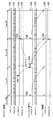
図1は、第一実施形態の映像処理システムの装置の構成例を示すブロック図である。映像処理システム1は、マスタ装置10とスレーブ装置20、表示パネル2を備え、マスタ装置10とスレーブ装置20はゲンロック信号3で接続される。表示パネル2は、マスタ装置10とスレーブ装置20からのパネル駆動信号によって駆動される。マスタ装置10は、映像処理システム1の全体の動作の基準となる同期信号を生成する。マスタ装置10は、表示パネルを駆動するためのマスタパネル駆動信号4を出力すると共に、スレーブ装置20に対してゲンロック信号3を出力する。スレーブ装置20は、マスタ装置10からのゲンロック信号3を受信して同期信号を生成し、表示パネル2を駆動するためのスレーブパネル駆動信号5を出力する。
<Configuration of video processing system (FIG. 1)>
FIG. 1 is a block diagram illustrating a configuration example of an apparatus of the video processing system according to the first embodiment. The
表示パネル2は、動画像などを表示するディスプレイである。表示パネル2は、液晶やプラズマ、LED、有機EL等で構成される直視型ディスプレイや、LCOS素子で構成される投射型ディスプレイ等の任意の方式で構成される。表示パネル2の画面は複数の領域に分割されており、領域毎に分割駆動される。表示パネル2の領域毎に同期信号と映像信号を入力することで映像の表示が行なわれる。
The
次に、マスタ装置10の内部構成を説明する。マスタ映像入力部18は、第1の映像信号としての、表示パネル2の表示対象の映像データを入力する。映像データは、たとえばHDMIやDVI、ディスプレイポート等の各種インタフェース規格に基づいた伝送方式で入力される。マスタ画像処理部19は、表示パネル2の画面に表示するのに必要な画像処理を行なう。そのような画像処理の例としては、表示パネル2の画角に合わせるためのスケーリング処理や、パネル表示特性に合わせるための色変換処理等が挙げられる。
Next, the internal configuration of the
マスタ同期信号生成部11は、映像処理システム1の全体の動作の基準となる同期信号を生成する。たとえば、マスタ同期信号生成部11で生成される同期信号は、表示パネル2の画面を構成するための垂直及び水平方向の基準タイミングを与える。また、マスタ同期信号生成部11は、入力された映像データのフレームまたはフィールドと位相を合わせるためのタイミング調整も行なう。マスタ遅延調整部12は、マスタ同期信号生成部11の同期信号を遅延させる。このような同期信号の遅延は、マスタ画像処理部19の処理レイテンシの調整や、スレーブ装置との間でパネル同期信号の出力タイミングを調整するのに使用される。
The master
マスタパネル駆動部13は、表示パネル2を駆動するためのマスタパネル駆動信号4を出力する。マスタパネル駆動信号4は、表示パネル2の表示タイミングを規定する同期信号と、表示する画素データを示す映像信号で構成される。同期信号は、垂直同期信号や水平同期信号、有効領域を示すデータイネーブル信号等で構成される。マスタパネル駆動信号4は、たとえばLVTTLやLVDS、DVI、ディスプレイポート等の各種インタフェース規格に基づいた伝送方式で出力される。
The master
信号幅変調部14は、マスタ制御部16から外部同期要求があった場合にゲンロック信号の変形を行なう。本実施形態では、外部同期要求があった場合に、通常は1ライン幅である垂直同期信号の信号幅を3ライン幅に変更する。ゲンロック信号出力部15は、スレーブ装置20を同期動作させるためのゲンロック信号3を出力する。本実施形態のゲンロック信号は、垂直同期信号及び水平同期信号で構成される。なお、ゲンロック信号の波形タイミングの詳細は後述する。ゲンロック信号の伝送方式はLVTTL等のシングルエンド伝送でもよいし、LVDS等の差動伝送でもよい。マスタ制御部16は、CPU、メモリ、補助記憶装置、通信インタフェース等から構成され、マスタ装置10の全体の制御を行なう。また、マスタ制御部16は、ユーザからの指示を入力するためのユーザインタフェースも含む。信号幅変調部14は、外部同期要求用の垂直同期信号が出力されたタイミングでマスタ制御部16に対して割込み信号17を発生する。
The signal
次に、スレーブ装置20の内部構成を説明する。スレーブ映像入力部28は、第2の映像信号としての、表示パネル2の表示対象の映像データを入力する。スレーブ画像処理部29は、表示パネル2の画面に表示するのに必要な画像処理を行なう。ゲンロック信号入力部21は、マスタ装置10からのゲンロック信号3を入力する。信号幅検出部22は、ゲンロック信号入力部21が入力したゲンロック信号3の垂直同期信号の信号幅を検出する。本実施形態では、ゲンロック信号の水平同期信号を基準として使用して垂直同期信号の信号幅が計測されるため、信号幅をライン幅と記載することもある。信号幅検出部22は、垂直同期信号のライン幅が3ライン幅であることを検出した場合には、外部同期要求があったと判定して、スレーブ制御部27に対して割込み信号30を発生する。
Next, the internal configuration of the
スレーブ同期信号生成部24は、入力されたゲンロック信号に基づき、スレーブ装置20を動作させるための同期信号を生成する。スレーブ遅延調整部25は、スレーブ同期信号生成部24が生成した同期信号を遅延させる。スレーブパネル駆動部26は、表示パネル2を駆動するためのスレーブパネル駆動信号5を出力する。スレーブ制御部27は、スレーブ装置20の全体の制御を行なう。
The slave
<ゲンロック信号の波形タイミング(図2)>
図2は、第一実施形態による映像処理システム1におけるゲンロック信号3のタイミングを示す図である。ゲンロック信号は、垂直同期信号214(extout_vs)と水平同期信号125(extout_hs)の2本の信号を有する。垂直同期信号214の通常のパルス幅(信号幅)は水平同期信号125により規定される1ライン幅である。外部同期割込みリクエストがあった場合、マスタ装置10は、変形された垂直同期信号として3ライン幅の垂直同期信号を出力する。マスタ装置10では、垂直同期信号を変形したタイミングにより特定される映像信号のフレーム(本実施形態では、ゲンロック信号の垂直同期信号が変形された直後のフレーム)に同期して外部同期割り込みが発生し、表示制御が実行される。スレーブ装置20では、この垂直同期信号の変形(3ライン幅の垂直同期信号)を検出すると、垂直同期信号の変形が検出されたタイミングにより特定される映像信号のフレームに同期して、すなわち、次のフレームで外部同期割込みが発生する。
<Genlock signal waveform timing (FIG. 2)>
FIG. 2 is a diagram showing the timing of the
マスタ装置10において、垂直同期信号120と水平同期信号121は、マスタ同期信号生成部11の生成する同期信号である。垂直同期信号120は、各フレームの冒頭でアサートされる。水平同期信号121は、水平走査ラインの冒頭でアサートされる。外部同期割り込みリクエスト信号122は、マスタ制御部16のソフトウェアが行なう外部同期割込みのリクエストである。同期割り込みのリクエストは、たとえば、後述する表示モードの切換え等、表示処理の変更が必要になった場合に発生する。図2では、外部同期割り込みリクエスト信号パルス130のタイミングで外部同期割込みがリクエストされている。外部同期割込みがリクエストされた場合、マスタ制御部16は、次のフレームでゲンロック信号の変形が行われるように信号幅変調部14を制御する。信号幅変調部14はゲンロック信号の垂直同期信号124を変形(ライン幅を3ライン幅へ変形)し(垂直同期信号パルス133)、その次のフレームでマスタ制御部16に対して外部同期割込み信号123をアサートする(タイミング131)。こうして、外部同期割込みリクエスト信号パルス130に応じて、タイミング131で外部同期割込みがアサートされる。
In the
ゲンロック信号の垂直同期信号124と水平同期信号125は、マスタ同期信号生成部11の生成する同期信号に基づいて出力される。垂直同期信号124は、各フレームの冒頭でアサートされる。水平同期信号125は、水平走査ラインの冒頭でアサートされる。垂直同期信号124は、通常のフレームでは1ライン幅の垂直同期信号パルス132として出力されるが、外部同期割込みのリクエストがあった次のフレームでは、上述のように3ライン幅の垂直同期信号パルス133が出力される。図2では、#1のフレームで発生した外部同期割り込みリクエストに応じて、#2のフレームで3ライン幅の垂直同期信号パルス133が出力されている。
The genlock signal
スレーブ装置20のスレーブ同期信号生成部24が生成する垂直同期信号126は、入力されたゲンロック信号(垂直同期信号124)のタイミングに基づいて生成される。信号幅検出部22は、3ライン幅のゲンロック用の垂直同期信号を検出すると、次のフレームで外部同期割込み信号127をアサートする。図2では、3ライン幅の垂直同期信号パルス133に応じて、タイミング134で外部同期割込み127がアサートされている。スレーブ装置20における外部同期割込み信号127がアサートされるタイミング134は、3ライン幅の垂直同期信号パルス133の次の垂直同期信号のタイミングである。したがって、外部同期割込み信号127は、マスタ外部同期割込み信号123(タイミング131)と同じフレームまたはフレームで割込みが発生していることになる。
The
以上のようにゲンロック信号の変形と検出を行なうことで、一つの外部同期割り込みリクエストに応じてマスタ装置10とスレーブ装置20は同じフレームで割込みを発生することができる。
By modifying and detecting the genlock signal as described above, the
<フレーム同期の処理の流れ(図3)>
図3は、第一実施形態の映像処理システムにおけるフレーム同期処理の流れを示すフローチャートである。ユーザが表示モードを切換える指示を入力した場合、外部同期割込みを発生させることにより割込みが発生した映像コマで切換え制御が行われる。なお、表示モードの切換えとしては、例えば、通常の室内で鑑賞するための「ノーマルモード」から暗い室内で映画を観賞するための「シネマモード」に切換えることが挙げられる。このような場合、それぞれのモードに応じた映像表示をするために、画像処理部の画像処理パラメータを表示モードに合わせて切換える。
<Flow of frame synchronization processing (FIG. 3)>
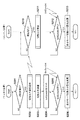
FIG. 3 is a flowchart showing a flow of frame synchronization processing in the video processing system of the first embodiment. When the user inputs an instruction to switch the display mode, switching control is performed on the video frame where the interrupt has occurred by generating an external synchronization interrupt. The switching of the display mode includes, for example, switching from “normal mode” for viewing in a normal room to “cinema mode” for watching a movie in a dark room. In such a case, the image processing parameter of the image processing unit is switched in accordance with the display mode in order to display a video according to each mode.
ステップS201〜S206は、マスタ装置10のマスタ制御部16が行なう処理である。ステップS201では、マスタ制御部16はユーザインタフェース(不図示)からの指示が入力されるのを待つ。ユーザからの指示があった場合、処理はステップS202に進み、指示がない場合はステップS201を再度実行する。ステップS202では、マスタ制御部16は、スレーブ装置20に対して表示モードの切換えの内容を通知する。この通知は所定の通信インタフェース(不図示)を通じて行われる。ステップS203では、新たな表示モードの設定値を検索または生成して、表示モード切換えの準備を行なう。
Steps S201 to S206 are processes performed by the
ステップS204では、マスタ制御部16は、信号幅変調部14に対して外部同期割込みのリクエストを行なう。すなわち、信号幅変調部14に外部同期割込みのリクエストの設定を行ない、次のフレームのゲンロック信号に3ライン幅の垂直同期信号が出力されるようにする。ステップS205では、マスタ制御部16は、外部同期割込み信号123がアサートされる(外部同期割込みが発生する)のを待つ。外部同期割込みが発生した場合、処理はステップS206に進み、発生していない場合はステップS205を再度実行する。ステップS206では、マスタ制御部16は、表示モード切換えのための設定変更を実行することにより表示制御を実行する(第1の実行処理)。たとえば、マスタ制御部16は、マスタ映像入力部18やマスタ画像処理部19の設定レジスタを新たな表示モード用の設定に書き換える。
In step S <b> 204, the
ステップS210〜S213は、スレーブ装置20のスレーブ制御部27が行なう処理である。ステップS210では、スレーブ制御部27は、マスタ装置10から切換え内容が通知されるのを待ち、切換え内容が通知されると処理をステップS211へ進める。ステップS211では、スレーブ制御部27は、新たな表示モードの設定値を検索または生成して、表示モード切換えの準備を行なう。ステップS212では、スレーブ制御部27は、外部同期割込み信号127がアサートされる(外部同期割り込みが発生する)のを待つ。外部同期割込みが発生した場合、処理はステップS213に進み、発生していない場合はステップS212が再度実行される。上述したように、外部同期割り込みは信号幅検出部22により出力される。ステップS213では、スレーブ制御部27は、表示モード切換えのための設定変更を行なうことにより表示制御を実行する(第2の実行処理)。スレーブ映像入力部28やスレーブ画像処理部29の設定レジスタを新たな表示モード用の設定に書き換える。
Steps S210 to S213 are processes performed by the
以上のように制御することで、マスタ装置とスレーブ装置は同じ映像コマで表示モード切換えを行なうことができる。すなわち、第一実施形態によれば、ゲンロック用の信号線数を増やさずに、簡単な構成で、確実に複数の映像装置の制御を同期させることができるという効果がある。 By controlling as described above, the master device and the slave device can switch the display mode with the same video frame. That is, according to the first embodiment, it is possible to reliably synchronize the control of a plurality of video apparatuses with a simple configuration without increasing the number of signal lines for genlock.
なお、本発明は、上述の実施形態に限定されるものではなく、幅広く応用することが可能である。たとえば、上記実施形態では外部同期要求を伝達するのに3ライン幅の垂直同期信号を使用したが、これに限られるものではなく、任意の信号幅を用いるなど、垂直同期信号に対する任意の変形を用いることができる。たとえば、垂直同期信号の信号幅を、ライン幅の単位で規定してもよいし、パルスがアサートされている時間で規定するようにしてもよい。更に、垂直同期信号をアナログ波形として伝達する場合には、パルスの高さ(信号電圧)で規定するようにしてもよい。また、水平同期信号の変形を用いるようにしてもよい。また、垂直同期信号と水平同期信号の形状の組み合わせにより外部同期要求を伝達するようにしてもよい。また、垂直同期信号、水平同期信号の変形のさせ方、あるいはそれら変形の組み合わせ方により、表示制御の内容を通知するようにしてもよい。たとえば、ゲンロック信号の垂直同期信号の信号幅が2ライン幅に変形された場合と、3ライン幅に変形された場合で異なる表示制御(表示処理の変更)を実行するようにすることができる。 Note that the present invention is not limited to the above-described embodiment, and can be widely applied. For example, in the above embodiment, a vertical synchronization signal having a three-line width is used to transmit an external synchronization request, but the present invention is not limited to this. Can be used. For example, the signal width of the vertical synchronization signal may be defined in units of line width, or may be defined in terms of the time when the pulse is asserted. Further, when the vertical synchronizing signal is transmitted as an analog waveform, it may be defined by the height of the pulse (signal voltage). Moreover, you may make it use the deformation | transformation of a horizontal synchronizing signal. Further, the external synchronization request may be transmitted by combining the shapes of the vertical synchronization signal and the horizontal synchronization signal. Further, the contents of the display control may be notified depending on how the vertical synchronization signal and the horizontal synchronization signal are modified, or how these modifications are combined. For example, it is possible to execute different display control (change of display processing) when the signal width of the vertical synchronization signal of the genlock signal is deformed to 2 line width and when it is deformed to 3 line width.
また、第一実施形態では、表示モード切換えの制御を同期させる例を説明したが、同期させる制御は任意のものでよい。たとえば、メーカーのロゴ画面やブルーバック画面への切換え、復帰の制御であってもよい。 In the first embodiment, the example in which the display mode switching control is synchronized has been described. However, the synchronization control may be arbitrary. For example, switching to a manufacturer's logo screen or blue back screen, or control of return may be used.
また、上述した同期割り込み処理への適用が可能な表示処理の変更の別の例として、入出力のフレームレートが一致しない場合に行なうティアリング防止の制御を挙げることができる。ティアリング防止処理とは、例えば59.94Hzの映像入力を60Hzで表示するような場合に、1001コマに1回だけ二度出しのコマを挿入することで、入出力のフレームレートを一致させる処理である。第一実施形態の構成によれば、マスタ装置10とスレーブ装置20において、同じ映像コマでコマ飛ばしや二度出しを行なうように制御することができる。
In addition, another example of the change in the display process that can be applied to the above-described synchronous interrupt process is a control for preventing tearing performed when the input / output frame rates do not match. The tearing prevention process is a process for matching the input / output frame rates by inserting a frame that is only once in 1001 frames, for example, when displaying 59.94 Hz video input at 60 Hz. is there. According to the configuration of the first embodiment, the
なお、第一実施形態では、ゲンロック信号の同期信号(垂直同期信号)が変形された次のフレームに同期して表示制御(表示モードの切り替え)が行われるようにしたが、これに限られるものではない。たとえば、ゲンロック信号の同期信号(垂直同期信号)が変形されたフレームから所定番目のフレームに同期して表示制御を実行するようにしてもよい。 In the first embodiment, the display control (switching of the display mode) is performed in synchronization with the next frame in which the synchronization signal (vertical synchronization signal) of the genlock signal is modified. However, the present invention is not limited to this. is not. For example, display control may be executed in synchronization with a predetermined frame from a frame in which the synchronization signal (vertical synchronization signal) of the genlock signal is modified.
なお、第一実施形態では、それぞれが別の筐体を持つマスタ装置とスレーブ装置で構成される例を説明したが、マスタ装置とスレーブ装置はLSIであってもよい。マスタLSIとスレーブLSIが基板上に実装され、基板上の信号パターンやケーブル配線によってゲンロック信号が伝達されるような構成にしてもよい。 In the first embodiment, an example in which each of the master device and the slave device has separate housings has been described. However, the master device and the slave device may be LSIs. A master LSI and a slave LSI may be mounted on a substrate, and a genlock signal may be transmitted by a signal pattern or cable wiring on the substrate.
[第二実施形態]
映像コマの同期は事前に行なってもよい。第二実施形態では、ゲンロック割込みを使用して起動時にマスタ装置10とスレーブ装置20の映像コマ同期を行なっておき、表示モード切換えを行なう例を説明する。なお、第二実施形態の映像処理システムの構成とゲンロック信号の波形は、前述の第一実施形態と同様である。但し、第二実施形態においては、マスタ制御部16とスレーブ制御部27のメモリ中に、それぞれフィールド数をカウントするための第1のカウンタ、第2のカウンタとして、フィールド番号カウンタを設ける。マスタ制御部16とスレーブ制御部27のそれぞれは、新たなフィールドが開始される毎にこのフィールド番号カウンタをインクリメントする。
[Second Embodiment]
Video frames may be synchronized in advance. In the second embodiment, an example will be described in which video frames are synchronized between the
<フィールド同期の処理の流れ(図4)>
図4は、第二実施形態の映像処理システムのフィールド同期処理の流れを示すフローチャートである。装置の起動時に外部同期割込みを発生させて、フィールド番号カウンタの同期を行なっておく。ユーザが表示モード切換えの指示を入力した場合、同じフィールド番号のフィールドで表示モード切換えの制御を行なう。ステップS221〜S228は、マスタ装置10のマスタ制御部16が行なう処理であり、ステップS230〜S235はスレーブ装置20のスレーブ制御部27が行う処理である。
<Flow of field synchronization processing (FIG. 4)>
FIG. 4 is a flowchart showing the flow of field synchronization processing of the video processing system according to the second embodiment. An external synchronization interrupt is generated when the apparatus is activated, and the field number counter is synchronized. When the user inputs a display mode switching instruction, the display mode switching is controlled in the field having the same field number. Steps S221 to S228 are processes performed by the
ステップS221〜S223、ステップS230〜S231の処理では、マスタ装置10とスレーブ装置20との間で現在のフィールド番号の値を一致させる。まず、ステップS221では、マスタ制御部16が信号幅変調部14に外部同期割込みのリクエストを行なう。第一実施形態(図2)で説明したように、マスタ制御部16は、信号幅変調部14に設定を行なって、次のフィールドのゲンロック信号に3ライン幅の垂直同期信号が出力されるようにする。ステップS222では、マスタ制御部16は、外部同期割込みが発生するのを待つ。外部同期割込みが発生した場合、処理はステップS223に進み、発生していない場合はステップS222を再度実行する。ステップS223では、マスタ制御部16は、フィールド番号カウンタの値をリセットする。
In the processing of steps S221 to S223 and steps S230 to S231, the current field number values are matched between the
ステップS224〜228は、ユーザからの表示モード切換えの指示があった場合に、マスタ制御部16が表示モードの切換えのための設定変更を行なう処理である。ステップS224では、マスタ制御部16は、ユーザインタフェースから表示モードの切換え指示が入力されるのを待つ。ユーザから切換え指示があった場合、処理はステップS225に進み、指示がない場合はステップS224を再度実行する。ステップS225では、マスタ制御部16は、スレーブ装置20に対して切換えの内容と切換えを行なうフィールド番号を通知する。例えば、マスタ制御部16は、現在のフィールド番号に所定数を加算して「x」という値を得て、「#x番目のフィールドで切換える」ことをスレーブ装置20に通知する。この通知は不図示の通信インタフェースを通じて行なう。
Steps S224 to 228 are processes in which the
ステップS226では、マスタ制御部16は、新たな表示モードのための設定値を検索または生成して、表示モード切換えの準備を行なう。ステップS227では、マスタ制御部16は、#x番目のフィールドが開始されるのを待つ。#x番目のフィールドが開始される場合、処理はステップS228に進み、異なるフィールドの場合はステップS227を再度実行する。ステップS228では、マスタ制御部16は、マスタ映像入力部18やマスタ画像処理部19の設定レジスタを新たな表示モード用の設定に書き換えて、表示モード切換えのための設定変更を行なう。これにより、上述した第1の実行処理(ステップS206)と同様に、表示制御が実行される。
In step S226,
ステップS230では、スレーブ制御部27は、外部同期割込みが発生するのを待つ。外部同期割込みが発生した場合、処理はステップS231に進み、発生しない場合はステップS230を再度実行する。ステップS231では、スレーブ制御部27は、フィールド番号カウンタの値をリセットする。
In step S230, the
ステップS232〜S235は、スレーブ制御部27による表示モードの設定変更処理である。ステップS232では、スレーブ制御部27は、マスタ装置10から切換え内容(切替えを実行するフィールド番号「x」を含む)が通知されるのを待ち、切換え内容が通知されると処理をステップS233へ進める。ステップS233では、スレーブ制御部27は、通知された内容に従って新たな表示モードのための設定値を検索または生成し、表示モードの切換えの準備を行なう。ステップS234では、スレーブ制御部27は、#x番目のフィールドが開始されるのを待つ。#x番目のフィールドが開始される場合、処理はステップS235に進み、異なるフィールドの場合はステップS234を再度実行する。ステップS235では、スレーブ制御部27は、表示モード切換えのための設定変更を行なう。スレーブ映像入力部28やスレーブ画像処理部29の設定レジスタを新たな表示モード用の設定に書き換える。これにより、上述した第2の実行処理(ステップS235)と同様に表示制御が実行される。
Steps S <b> 232 to S <b> 235 are display mode setting change processing by the
以上のように制御することで、マスタ装置10とスレーブ装置20において同じ映像コマで表示モード切換えを実行することができる。すなわち、第二実施形態によれば前述の第一実施形態と同様な効果を得ることができる。
By controlling as described above, the display mode can be switched in the same video frame in the
なお、本発明は、上述の実施形態に限定されるものではなく、幅広く応用することが可能である。また、第一実施形態では起動時に映像コマ同期を行なう例を説明したが、起動時に映像が入力されていない場合もある。この場合、映像が入力されたことを検出し、入力が検出された時点で映像コマ同期を行なうようにしてもよい。また、映像の表示中に、数秒〜数分程度の時間間隔で定期的に映像コマ同期を行なうようにしてもよい。また、上記第二実施形態において、マスタ装置10とスレーブ装置20で実行される表示制御(例えば切換え制御)の内容がそれぞれの装置において予め設定済みであれば、ステップS225における内容(切換える内容)の通知を省略してもよい。また、上記各実施形態においては、映像信号のフレームに同期した表示制御であってもよいし、フィールドに同期した表示制御であってもよい。たとえば、第二実施形態では、第1、第2のカウンタはフレーム数をカウントするカウンタであってもよい。
Note that the present invention is not limited to the above-described embodiment, and can be widely applied. In the first embodiment, an example in which video frame synchronization is performed at the time of startup has been described. However, there is a case where video is not input at the time of startup. In this case, it may be detected that video has been input, and video frame synchronization is performed when the input is detected. Further, during the video display, video frame synchronization may be periodically performed at time intervals of several seconds to several minutes. In the second embodiment, if the contents of display control (for example, switching control) executed by the
また、本発明は、以下の処理を実行することによっても実現される。即ち、上述した実施形態の機能を実現するソフトウェア(プログラム)を、ネットワーク又は各種記憶媒体を介してシステム或いは装置に供給し、そのシステム或いは装置のコンピュータ(またはCPUやMPU等)がプログラムを読み出して実行する処理である。 The present invention can also be realized by executing the following processing. That is, software (program) that realizes the functions of the above-described embodiments is supplied to a system or apparatus via a network or various storage media, and a computer (or CPU, MPU, or the like) of the system or apparatus reads the program. It is a process to be executed.
Claims (21)
前記第1の映像処理装置は、
映像データに基づく映像の表示処理を変更するタイミングを特定する特定手段と、
表示処理の変更の内容を前記第2の映像処理装置に通知する通知手段と、
前記第1及び第2の映像処理装置によりそれぞれ出力される映像データに基づく映像の表示を同期させるために前記第1の映像処理装置から前記第2の映像処理装置へ出力されるゲンロック信号を生成する生成手段であって、前記ゲンロック信号に含まれる複数の同期信号パルスのうち、前記特定手段により特定された前記タイミングによって示される同期信号パルスが変形されたゲンロック信号を生成する生成手段と、
前記第1の映像処理装置が出力する映像データに対応する複数のフレームまたはフィールドのうち、前記変形された同期信号パルスに対応するフレームまたはフィールドに同期して表示処理の変更を実行する第1の実行手段と、を備え、
前記第2の映像処理装置は、
前記第1の映像処理装置から出力された前記ゲンロック信号に含まれる複数の同期信号パルスのうち、前記変形された同期信号パルスを検出する検出手段と、
前記第2の映像処理装置が出力する映像データに対応する複数のフレームまたはフィールドのうち、前記検出手段が検出した前記変形された同期信号パルスに対応するフレームまたはフィールドに同期して、前記通知手段により通知された内容にしたがって表示処理の変更を実行する第2の実行手段と、を備えることを特徴とする映像処理システム。 A video processing system that synchronizes display of video based on video data output from each of a first video processing device and a second video processing device using a genlock signal output from the first video processing device. And
The first video processing device includes:
A specifying means for specifying the timing for changing the video display processing based on the video data;
Notification means for notifying the second video processing device of the content of the change in display processing;
Generating a genlock signal output from the first video processing device to the second video processing device in order to synchronize the display of the video based on the video data output from the first and second video processing devices, respectively. Generating means for generating a genlock signal in which a synchronization signal pulse indicated by the timing specified by the specifying means is modified among a plurality of synchronization signal pulses included in the genlock signal; and
A first change in display processing is performed in synchronization with a frame or field corresponding to the modified sync signal pulse among a plurality of frames or fields corresponding to video data output by the first video processing device. An execution means,
The second video processing device includes:
Detecting means for detecting the modified synchronization signal pulse among a plurality of synchronization signal pulses included in the genlock signal output from the first video processing device;
Of the plurality of frames or fields corresponding to the video data output by the second video processing device , the notifying means is synchronized with the frame or field corresponding to the modified sync signal pulse detected by the detecting means. And a second execution means for executing a change in display processing in accordance with the content notified by the video processing system.
前記第1の映像処理装置から前記第2の映像処理装置へ前記変更を実行するフレーム数またはフィールド数を通知する通知手段と、
前記第2の映像処理装置において前記変形が検出された同期信号パルスに対応するフレームまたはフィールドからのフレーム数またはフィールド数をカウントする第2のカウンタと、を更に備え、
前記第1の実行手段は、前記第1のカウンタが、前記通知手段が通知したフレーム数またはフィールド数に達したときのフレームまたはフィールドに同期して前記変更を実行し、
前記第2の実行手段は、前記第2のカウンタが、前記通知手段により通知されたフレーム数またはフィールド数に達したときのフレームまたはフィールドに同期して前記変更を実行することを特徴とする請求項1乃至4のいずれか1項に記載の映像処理システム。 A first counter that counts the number of frames or fields from the frame or field corresponding to the synchronization signal pulse for which the deformation has been performed in the first video processing device;
Notification means for notifying the number of frames or fields for executing the change from the first video processing apparatus to the second video processing apparatus;
A second counter that counts the number of frames or fields from the frame or field corresponding to the synchronization signal pulse in which the deformation is detected in the second video processing device;
The first execution means executes the change in synchronization with a frame or field when the first counter reaches the number of frames or fields notified by the notification means,
The second execution means executes the change in synchronization with a frame or field when the second counter reaches the number of frames or fields notified by the notification means. Item 5. The video processing system according to any one of Items 1 to 4 .
前記第1の映像処理装置は、
前記第1及び第2の映像処理装置によりそれぞれ出力される映像データに基づく映像の表示を同期させるために前記第1の映像処理装置から前記第2の映像処理装置へ出力されるゲンロック信号を生成する生成手段であって、前記ゲンロック信号に含まれる複数の同期信号パルスのうち、同期信号パルスが変形されたゲンロック信号を生成する、生成手段と、
前記変形された同期信号パルスに対応するフレームまたはフィールドからのフレーム数またはフィールド数をカウントする第1のカウンタと、
前記第2の映像処理装置へ表示処理の変更を実行するフレーム数またはフィールド数を通知する通知手段と、
前記第1のカウンタが、前記通知手段が通知したフレーム数またはフィールド数に達したときのフレームまたはフィールドに同期して前記変更を実行する第1の実行手段と、を備え、
前記第2の映像処理装置は、
前記第1の映像処理装置から出力された前記ゲンロック信号に含まれる複数の同期信号パルスのうち、前記変形された同期信号パルスを検出する検出手段と、
前記検出手段により前記変形が検出された同期信号パルスに対応するフレームまたはフィールドからのフレーム数またはフィールド数をカウントする第2のカウンタと、
前記第2のカウンタが、前記通知手段により通知されたフレーム数またはフィールド数に達したときのフレームまたはフィールドに同期して前記変更を実行する第2の実行手段と、を備えることを特徴とする映像処理システム。 A video processing system that synchronizes display of video based on video data output from each of a first video processing device and a second video processing device using a genlock signal output from the first video processing device. And
The first video processing device includes:
Generating a genlock signal output from the first video processing device to the second video processing device in order to synchronize the display of the video based on the video data output from the first and second video processing devices, respectively. Generating means for generating a genlock signal in which a synchronization signal pulse is transformed among a plurality of synchronization signal pulses included in the genlock signal; and
A first counter for counting the number of clicks or field frames from the frame or field corresponding to the synchronizing signal pulses before Symbol deformation,
And notifying means for notifying the front number system number or field or frame to perform the change of the display processing to the second video processing device,
The first counter includes first execution means for executing the change in synchronization with a frame or a field when the number of frames or fields notified by the notification means is reached;
The second video processing device includes:
Detecting means for detecting the modified synchronization signal pulse among a plurality of synchronization signal pulses included in the genlock signal output from the first video processing device;
A second counter for counting the number of frames or fields from the frame or field corresponding to the synchronization signal pulse in which the deformation is detected by the detection means ;
And characterized in that it comprises pre-Symbol second counter, and a second execution unit configured to execute the changes in synchronism with the frame or field when it reaches the number of clicks or field frames notified by the notification means Film image processing system that.
前記第2の実行手段は、前記検出手段が変形した同期信号パルスに対応するフレームまたはフィールドの垂直同期信号に同期して割込み信号を発生する第2の発生手段を更に有し、該第2の発生手段が発生した割込み信号に応じて前記表示処理の変更を実行することを特徴とする請求項1乃至9のいずれか1項に記載の映像処理システム。 The first execution means further comprises a first generating means for generating an interrupt signal in synchronism with the frames or fields of the vertical synchronizing signal before Symbol generation means corresponds to the synchronizing signal pulses obtained by modifying, first The display process is changed in response to the interrupt signal generated by the generating means,
It said second execution means further comprises a second generating means for generating an interrupt signal in synchronization with the vertical synchronizing signal of the frame or field before Symbol detection means corresponds to the sync pulse deformed, second the video processing system according to any one of claims 1 to 9, characterized in that to perform a change of the display processing in response to the interrupt signal generating means has generated the.
映像データに基づく映像の表示処理を変更するタイミングを特定する特定手段と、
表示処理の変更の内容を他の映像処理装置に通知する通知手段と、
前記映像処理装置と前記他の映像処理装置によりそれぞれ出力される映像データに基づく映像の表示を同期させるために前記映像処理装置から前記他の映像処理装置へ出力されるゲンロック信号を生成する生成手段であって、前記ゲンロック信号に含まれる複数の同期信号パルスのうち、前記特定手段により特定された前記タイミングによって示される同期信号パルスが変形されたゲンロック信号を生成する生成手段と、
前記生成手段により生成されたゲンロック信号を前記他の映像処理装置へ出力する出力手段と、
前記映像処理装置が出力する映像データに対応する複数のフレームまたはフィールドのうち、前記変形された同期信号パルスに対応するフレームまたはフィールドに同期して、表示処理の変更を実行する実行手段と、を備えることを特徴とする映像処理装置。 A video processing device for displaying video based on video data,
A specifying means for specifying the timing for changing the video display processing based on the video data;
Notification means for notifying other video processing devices of the content of the display processing change;
Generating means for generating a genlock signal to be output to the other image processing apparatus from the image processing apparatus for synchronizing the display of video based on the video data output respectively to the image processing apparatus by the other video processing device And generating means for generating a genlock signal in which a synchronization signal pulse indicated by the timing specified by the specifying means is transformed among a plurality of synchronization signal pulses included in the genlock signal;
Output means for outputting the genlock signal generated by the generating means to the other video processing device;
Among a plurality of frames or fields corresponding to the image data to which the image processing device outputs, in synchronism with the frame or field corresponding to the modified synchronization signal pulses, and execution means for executing a change in the display process, the A video processing apparatus comprising:
他の映像処理装置から表示処理の変更の内容の通知を受信する第1の受信手段と、
前記映像処理装置と前記他の映像処理装置によりそれぞれ出力される映像データに基づく映像の表示を同期させるために前記他の映像処理装置から出力されるゲンロック信号であって、複数の同期信号パルスのうち、前記映像の表示処理を変更するタイミングに応じた同期信号パルスが変形されたゲンロック信号を受信する第2の受信手段と、
前記他の映像処理装置から受信した前記ゲンロック信号に含まれる複数の同期信号パルスのうち、前記変形された同期信号パルスを検出する検出手段と、
前記映像処理装置が出力する映像データに対応する複数のフレームまたはフィールドのうち、前記検出手段が検出した前記変形された同期信号パルスに対応するフレームまたはフィールドに同期して、前記第1の受信手段により受信された内容にしたがって表示処理の変更を実行する実行手段と、を備えることを特徴とする映像処理装置。 A video processing device for displaying video based on video data,
First receiving means for receiving notification of changes in display processing from another video processing device;
A genlock signal output from the other image processing apparatus for synchronizing the display of video based on the video data output respectively to the image processing apparatus by the other video processing device, a plurality of sync pulse Among them, a second receiving means for receiving a genlock signal in which a synchronization signal pulse corresponding to a timing for changing the video display processing is modified;
Detection means for detecting the modified synchronization signal pulse among a plurality of synchronization signal pulses included in the genlock signal received from the other video processing device;
Of the plurality of frames or fields corresponding to the video data output by the video processing device , the first receiving means is synchronized with the frame or field corresponding to the modified sync signal pulse detected by the detecting means. And an execution means for executing a change in display processing in accordance with the content received by the video processing apparatus.
前記映像処理装置と他の映像処理装置によりそれぞれ出力される映像データに基づく映像の表示を同期させるために前記映像処理装置から前記他の映像処理装置へ出力されるゲンロック信号を生成する生成手段であって、前記ゲンロック信号に含まれる複数の同期信号パルスのうち、同期信号パルスが変形されたゲンロック信号を生成する生成手段と、 Generation means for generating a genlock signal output from the video processing device to the other video processing device in order to synchronize display of video based on video data respectively output by the video processing device and the other video processing device; A generating means for generating a genlock signal in which the synchronization signal pulse is transformed among the plurality of synchronization signal pulses included in the genlock signal;
前記変形された同期信号パルスに対応するフレームまたはフィールドからのフレーム数またはフィールド数をカウントするカウンタと、 A counter that counts the number of frames or fields from the frame or field corresponding to the modified sync signal pulse;
前記他の映像処理装置へ表示処理の変更を実行するフレーム数またはフィールド数を通知する通知手段と、 A notification means for notifying the other video processing device of the number of frames or the number of fields for executing a change in display processing;
前記カウンタが、前記通知手段が通知したフレーム数またはフィールド数に達したときのフレームまたはフィールドに同期して前記変更を実行する実行手段と、を備えることを特徴とする映像処理装置。 An image processing apparatus comprising: an execution unit that executes the change in synchronization with a frame or a field when the counter reaches the number of frames or fields notified by the notification unit.
他の映像処理装置からの、表示処理の変更を実行するフレーム数またはフィールド数の通知を受信する第1の受信手段と、 First receiving means for receiving a notification of the number of frames or the number of fields for executing a change in display processing from another video processing device;
前記映像処理装置と前記他の映像処理装置によりそれぞれ出力される映像データに基づく映像の表示を同期させるために前記他の映像処理装置から出力されるゲンロック信号であって、複数の同期信号パルスのうち、前記映像の表示処理を変更するタイミングに応じた同期信号パルスが変形されたゲンロック信号を受信する第2の受信手段と、 A genlock signal output from the other video processing device to synchronize display of video based on video data respectively output by the video processing device and the other video processing device, and a plurality of synchronization signal pulses Among them, a second receiving means for receiving a genlock signal in which a synchronization signal pulse corresponding to a timing for changing the video display processing is modified;
前記第2の受信手段で受信された前記ゲンロック信号に含まれる複数の同期信号パルスのうち、変形された同期信号パルスを検出する検出手段と、 Detecting means for detecting a modified synchronizing signal pulse among a plurality of synchronizing signal pulses included in the genlock signal received by the second receiving means;
前記検出手段により前記変形が検出された同期信号パルスに対応するフレームまたはフィールドからのフレーム数またはフィールド数をカウントするカウンタと、 A counter that counts the number of frames or fields from the frame or field corresponding to the synchronization signal pulse in which the deformation is detected by the detection means;
前記カウンタが、前記第1の受信手段により受信された前記通知が示すフレーム数またはフィールド数に達したときのフレームまたはフィールドに同期して前記変更を実行する実行手段と、を備えることを特徴とする映像処理装置。 The counter includes execution means for executing the change in synchronization with a frame or field when the number of frames or fields indicated by the notification received by the first receiving means is reached. Video processing device.
前記第1の映像処理装置が、映像データに基づく映像の表示処理を変更するタイミングを特定する特定する特定工程と、
前記第1の映像処理装置が、表示処理の変更の内容を前記第2の映像処理装置に通知する通知工程と、
前記第1の映像処理装置が、前記第1及び第2の映像処理装置によりそれぞれ出力される映像データに基づく映像の表示を同期させるために前記第1の映像処理装置から前記第2の映像処理装置へ出力されるゲンロック信号を生成する生成工程であって、前記ゲンロック信号に含まれる複数の同期信号パルスのうち、前記特定工程で特定された前記タイミングによって示される同期信号パルスが変形されたゲンロック信号を生成する生成工程と、
前記第1の映像処理装置が、前記第1の映像処理装置が出力する映像データに対応する複数のフレームまたはフィールドのうち、前記変形された同期信号パルスに対応するフレームまたはフィールドに同期して表示処理の変更を実行する第1の実行工程と、
前記第2の映像処理装置が、前記第1の映像処理装置から出力された前記ゲンロック信号に含まれる複数の同期信号パルスのうち、前記変形された同期信号パルスを検出する検出工程と、
前記第2の映像処理装置が、前記第2の映像処理装置が出力する映像データに対応する複数のフレームまたはフィールドのうち、前記検出工程で検出された前記変形された同期信号パルスに対応するフレームまたはフィールドに同期して、前記通知工程で通知された内容にしたがって表示処理の変更を実行する第2の実行工程と、を有することを特徴とする映像処理システムの制御方法。 Control of video processing system for synchronizing display of video based on video data output from each of first video processing device and second video processing device using genlock signal output from said first video processing device A method,
A specifying step of specifying the timing at which the first video processing device changes video display processing based on video data;
A notification step in which the first video processing device notifies the second video processing device of a change in display processing;
The first video processing device performs the second video processing from the first video processing device in order to synchronize the display of the video based on the video data respectively output by the first and second video processing devices. A generation process for generating a genlock signal to be output to a device, wherein a genlock in which a synchronization signal pulse indicated by the timing specified in the specific process is deformed among a plurality of synchronization signal pulses included in the genlock signal A generating step for generating a signal;
The first video processing device displays in synchronization with a frame or field corresponding to the modified sync signal pulse among a plurality of frames or fields corresponding to video data output by the first video processing device. A first execution step for executing a process change;
A detection step in which the second video processing device detects the deformed synchronization signal pulse among a plurality of synchronization signal pulses included in the genlock signal output from the first video processing device;
The second video processing device corresponds to the modified sync signal pulse detected in the detection step among a plurality of frames or fields corresponding to video data output from the second video processing device. Or a second execution step of executing a change in display processing in accordance with the content notified in the notification step in synchronization with a field.
前記第1の映像処理装置が、前記第1及び第2の映像処理装置によりそれぞれ出力される映像データに基づく映像の表示を同期させるために前記第1の映像処理装置から前記第2の映像処理装置へ出力されるゲンロック信号を生成する生成工程であって、前記ゲンロック信号に含まれる複数の同期信号パルスのうち、同期信号パルスが変形されたゲンロック信号を生成する、生成工程と、 The first video processing device performs the second video processing from the first video processing device in order to synchronize the display of the video based on the video data respectively output by the first and second video processing devices. A generation step of generating a genlock signal to be output to the device, wherein a generation step of generating a genlock signal in which a synchronization signal pulse is transformed among a plurality of synchronization signal pulses included in the genlock signal;
前記第1の映像処理装置が、前記変形された同期信号パルスに対応するフレームまたはフィールドからのフレーム数またはフィールド数をカウントする第1のカウント工程と、 A first counting step in which the first video processing device counts the number of frames or fields from the frame or field corresponding to the modified sync signal pulse;
前記第1の映像処理装置が、前記第2の映像処理装置へ表示処理の変更を実行するフレーム数またはフィールド数を通知する通知工程と、 A notification step in which the first video processing device notifies the second video processing device of the number of frames or the number of fields to be changed in display processing;
前記第1の映像処理装置が、前記第1のカウント工程によるカウント数が、前記通知工程で通知されたフレーム数またはフィールド数に達したときのフレームまたはフィールドに同期して前記変更を実行する第1の実行工程と、 The first video processing device executes the change in synchronization with the frame or field when the count number in the first counting step reaches the frame number or field number notified in the notification step. 1 execution process;
前記第2の映像処理装置が、前記第1の映像処理装置から出力された前記ゲンロック信号に含まれる複数の同期信号パルスのうち、前記変形された同期信号パルスを検出する検出工程と、 A detection step in which the second video processing device detects the deformed synchronization signal pulse among a plurality of synchronization signal pulses included in the genlock signal output from the first video processing device;
前記第2の映像処理装置が、前記検出工程で前記変形が検出された同期信号パルスに対応するフレームまたはフィールドからのフレーム数またはフィールド数をカウントする第2のカウント工程と、 A second counting step in which the second video processing device counts the number of frames or fields from the frame or field corresponding to the synchronization signal pulse in which the deformation is detected in the detection step;
前記第2の映像処理装置が、前記第2のカウント工程によるカウント数が、前記通知工程で通知されたフレーム数またはフィールド数に達したときのフレームまたはフィールドに同期して前記変更を実行する第2の実行工程と、を備えることを特徴とする映像処理システムの制御方法。 The second video processing device executes the change in synchronization with the frame or field when the count number in the second counting step reaches the frame number or field number notified in the notification step. And an execution step of the video processing system.
特定手段が、映像データに基づく映像の表示処理を変更するタイミングを特定する特定工程と、
通知手段が、表示処理の変更の内容を他の映像処理装置に通知する通知工程と、
生成手段が、前記映像処理装置と前記他の映像処理装置によりそれぞれ出力される映像データに基づく映像の表示を同期させるために前記映像処理装置から前記他の映像処理装置へ出力されるゲンロック信号を生成する生成工程であって、前記ゲンロック信号に含まれる複数の同期信号パルスのうち、前記特定工程で特定された前記タイミングによって示される同期信号パルスが変形されたゲンロック信号を生成する生成工程と、
出力手段が、前記生成工程で生成されたゲンロック信号を前記他の映像処理装置へ出力する出力工程と、
実行手段が、前記映像処理装置が出力する映像データに対応する複数のフレームまたはフィールドのうち、前記変形された同期信号パルスに対応するフレームまたはフィールドに同期して、表示処理の変更を実行する実行工程と、を有することを特徴とする映像処理装置の制御方法。 A control method of a video processing device for displaying video based on video data,
A specifying step in which the specifying means specifies the timing for changing the display processing of the video based on the video data;
A notification step of notifying the other video processing device of the content of the change in the display processing;
Generating means, a genlock signal output to the other image processing apparatus from the image processing apparatus for synchronizing the display of video based on the video data output respectively to the image processing apparatus by the other video processing device A generating step for generating a genlock signal in which a synchronizing signal pulse indicated by the timing specified in the specifying step is transformed among a plurality of synchronizing signal pulses included in the genlock signal; and
An output step for outputting the genlock signal generated in the generation step to the other video processing device;
Execution executing means, wherein among the plurality of frame or field corresponding to image data image processing device outputs, which in synchronism with the frame or field corresponding to said modified synchronizing signal pulses, to perform the change of the display processing And a process for controlling the video processing apparatus.
第1の受信手段が、他の映像処理装置から表示処理の変更の内容の通知を受信する第1の受信工程と、
第2の受信手段が、前記映像処理装置と前記他の映像処理装置によりそれぞれ出力される映像データに基づく映像の表示を同期させるために前記他の映像処理装置から出力されるゲンロック信号であって、複数の同期信号パルスのうち、前記映像の表示処理を変更するタイミングに応じた同期信号パルスが変形されたゲンロック信号を受信する第2の受信工程と、
検出手段が、前記他の映像処理装置から受信した前記ゲンロック信号に含まれる複数の同期信号パルスのうち、前記変形された同期信号パルスを検出する検出工程と、
実行手段が、前記映像処理装置が出力する映像データに対応する複数のフレームまたはフィールドのうち、前記検出工程で検出された前記変形された同期信号パルスに対応するフレームまたはフィールドに同期して、前記第1の受信工程で受信された内容にしたがって表示処理の変更を実行する実行工程と、を有することを特徴とする映像処理装置の制御方法。 A control method of a video processing device for displaying video based on video data,
A first receiving step in which a first receiving unit receives a notification of a change in display processing from another video processing device;
The second receiving means, a genlock signal output from the other image processing apparatus for synchronizing the display of video based on the video data output respectively to the image processing apparatus by the other video processing device A second reception step of receiving a genlock signal in which the synchronization signal pulse is transformed among the plurality of synchronization signal pulses according to the timing of changing the video display processing;
A detecting step for detecting the modified sync signal pulse among a plurality of sync signal pulses included in the genlock signal received from the other video processing device;
The execution means is synchronized with the frame or field corresponding to the modified synchronization signal pulse detected in the detection step among the plurality of frames or fields corresponding to the video data output by the video processing device , And an execution step of executing a change in display processing according to the content received in the first reception step .
生成手段が、前記映像処理装置と他の映像処理装置によりそれぞれ出力される映像データに基づく映像の表示を同期させるために前記映像処理装置から前記他の映像処理装置へ出力されるゲンロック信号を生成する生成手段であって、前記ゲンロック信号に含まれる複数の同期信号パルスのうち、同期信号パルスが変形されたゲンロック信号を生成する生成工程と、 A generation unit generates a genlock signal output from the video processing device to the other video processing device in order to synchronize display of video based on video data respectively output from the video processing device and the other video processing device. A generating step for generating a genlock signal in which a synchronization signal pulse is transformed among a plurality of synchronization signal pulses included in the genlock signal;
カウント手段が、前記変形された同期信号パルスに対応するフレームまたはフィールドからのフレーム数またはフィールド数をカウントするカウント工程と、 A counting step, wherein the counting means counts the number of frames or fields from the frame or field corresponding to the modified synchronization signal pulse;
通知手段が、前記他の映像処理装置へ表示処理の変更を実行するフレーム数またはフィールド数を通知する通知工程と、 A notification step of notifying the other video processing device of the number of frames or the number of fields for executing a change in display processing;
実行手段が、前記通知工程で通知されたフレーム数またはフィールド数に前記カウント工程によるカウント値が達したときのフレームまたはフィールドに同期して前記変更を実行する実行工程と、を備えることを特徴とする映像処理装置の制御方法。 An execution unit includes an execution step of executing the change in synchronization with a frame or a field when the count value of the counting step reaches the number of frames or fields notified in the notification step. Control method for video processing apparatus.
第1の受信手段が、他の映像処理装置からの、表示処理の変更を実行するフレーム数またはフィールド数の通知を受信する第1の受信工程と、 A first receiving step in which a first receiving means receives a notification of the number of frames or the number of fields for executing a change in display processing from another video processing device;
第2の受信手段が、前記映像処理装置と前記他の映像処理装置によりそれぞれ出力される映像データに基づく映像の表示を同期させるために前記他の映像処理装置から出力されるゲンロック信号であって、複数の同期信号パルスのうち、前記映像の表示処理を変更するタイミングに応じた同期信号パルスが変形されたゲンロック信号を受信する第2の受信工程と、 The second receiving means is a genlock signal output from the other video processing device to synchronize the display of the video based on the video data respectively output from the video processing device and the other video processing device. A second reception step of receiving a genlock signal in which the synchronization signal pulse is transformed among the plurality of synchronization signal pulses according to the timing of changing the video display processing;
検出手段が、前記第2の受信工程で受信された前記ゲンロック信号に含まれる複数の同期信号パルスのうち、変形された同期信号パルスを検出する検出工程と、 A detecting step for detecting a modified synchronizing signal pulse among a plurality of synchronizing signal pulses included in the genlock signal received in the second receiving step;
カウント手段が、前記検出工程により前記変形が検出された同期信号パルスに対応するフレームまたはフィールドからのフレーム数またはフィールド数をカウントするカウント工程と、 A counting step that counts the number of frames or fields from the frame or field corresponding to the synchronization signal pulse in which the deformation is detected by the detection step;
実行手段が、前記第1の受信工程で受信された前記通知が示すフレーム数またはフィールド数に前記カウント工程によるカウント値が達したときのフレームまたはフィールドに同期して前記変更を実行する実行工程と、を備えることを特徴とする映像処理装置の制御方法。 An execution step in which execution means executes the change in synchronization with a frame or field when the count value in the counting step reaches the number of frames or fields indicated by the notification received in the first reception step; A method for controlling a video processing apparatus, comprising:
Priority Applications (1)
| Application Number | Priority Date | Filing Date | Title |
|---|---|---|---|
| JP2013016133A JP6143477B2 (en) | 2013-01-30 | 2013-01-30 | Video processing system, video processing device, and control method thereof |
Applications Claiming Priority (1)
| Application Number | Priority Date | Filing Date | Title |
|---|---|---|---|
| JP2013016133A JP6143477B2 (en) | 2013-01-30 | 2013-01-30 | Video processing system, video processing device, and control method thereof |
Publications (3)
| Publication Number | Publication Date |
|---|---|
| JP2014146009A JP2014146009A (en) | 2014-08-14 |
| JP2014146009A5 JP2014146009A5 (en) | 2016-03-17 |
| JP6143477B2 true JP6143477B2 (en) | 2017-06-07 |
Family
ID=51426279
Family Applications (1)
| Application Number | Title | Priority Date | Filing Date |
|---|---|---|---|
| JP2013016133A Expired - Fee Related JP6143477B2 (en) | 2013-01-30 | 2013-01-30 | Video processing system, video processing device, and control method thereof |
Country Status (1)
| Country | Link |
|---|---|
| JP (1) | JP6143477B2 (en) |
Families Citing this family (1)
| Publication number | Priority date | Publication date | Assignee | Title |
|---|---|---|---|---|
| US11537347B2 (en) | 2020-09-14 | 2022-12-27 | Apple Inc. | Follower mode video operation |
Family Cites Families (9)
| Publication number | Priority date | Publication date | Assignee | Title |
|---|---|---|---|---|
| JPH06214534A (en) * | 1993-01-20 | 1994-08-05 | Hitachi Ltd | Multi-screen display device |
| JP3266402B2 (en) * | 1993-12-28 | 2002-03-18 | キヤノン株式会社 | Display device |
| JP3701794B2 (en) * | 1997-07-10 | 2005-10-05 | 株式会社ソニー・コンピュータエンタテインメント | Entertainment system, image display device, information processing device, and synchronization control method |
| JP4168510B2 (en) * | 1999-02-16 | 2008-10-22 | ソニー株式会社 | Signal processing circuit and signal processing system |
| JP2000250526A (en) * | 1999-02-26 | 2000-09-14 | Canon Inc | Method and device for image display control |
| JP2007206232A (en) * | 2006-01-31 | 2007-08-16 | Toshiba Matsushita Display Technology Co Ltd | Interface |
| JP2008051848A (en) * | 2006-08-22 | 2008-03-06 | Seiko Epson Corp | Display device, multi-display system, synchronous control method, synchronous control program, and recording medium |
| JP5224137B2 (en) * | 2009-07-27 | 2013-07-03 | 株式会社メガチップス | Display system and image reproduction apparatus |
| JP5615430B2 (en) * | 2011-05-11 | 2014-10-29 | 三菱電機株式会社 | Video information playback unit, video information playback device, and synchronization control method |
-
2013
- 2013-01-30 JP JP2013016133A patent/JP6143477B2/en not_active Expired - Fee Related
Also Published As
| Publication number | Publication date |
|---|---|
| JP2014146009A (en) | 2014-08-14 |
Similar Documents
| Publication | Publication Date | Title |
|---|---|---|
| US10049642B2 (en) | Sending frames using adjustable vertical blanking intervals | |
| US9786255B2 (en) | Dynamic frame repetition in a variable refresh rate system | |
| US10223980B2 (en) | Display device and display method | |
| JP6069354B2 (en) | Receiving apparatus, video refresh frequency control method, apparatus and system | |
| US7483031B2 (en) | Method for synchronizing graphics processing units | |
| US20100315427A1 (en) | Multiple graphics processing unit display synchronization system and method | |
| TWI722221B (en) | Method for adjusting output images and multi-picture display system | |
| KR20110078292A (en) | System for displaying multi video | |
| US10593298B2 (en) | Display control device, display control method, and display apparatus | |
| US20120007875A1 (en) | Multiple Monitor Video Control | |
| CN108597464B (en) | Control device and control method for liquid crystal display | |
| KR101416272B1 (en) | Display apparatus and control method thereof | |
| TW201428733A (en) | System, method, and computer program product for providing a dynamic display refresh | |
| JP2009152897A (en) | Stereoscopic video display device, stereoscopic video display method, and liquid crystal display | |
| KR101118647B1 (en) | Timing controller, method of driving the same and liquid crystal display device having the same | |
| CN110047448B (en) | Touch panel control device, touch panel control method, and input display device | |
| US9110514B2 (en) | Electronic device with switchable display screen, computer system thereof and method for switching display screen | |
| CN101383913B (en) | Display overlapping control system and control method thereof | |
| KR100555576B1 (en) | Apparatus and method for performing frame rate conversion without an external memory in the display system | |
| JP6143477B2 (en) | Video processing system, video processing device, and control method thereof | |
| WO2014048000A1 (en) | Driving method for liquid crystal display device and driving system thereof | |
| US20170075432A1 (en) | Cursor handling in a variable refresh rate environment | |
| JP2012078393A (en) | Multi-display device and video signal generation device | |
| JP2014147052A (en) | Video processing system, video processing device and method, and program | |
| CN114023273A (en) | Local dimming driving circuit, method and system and electronic equipment |
Legal Events
| Date | Code | Title | Description |
|---|---|---|---|
| A521 | Written amendment |
Free format text: JAPANESE INTERMEDIATE CODE: A523 Effective date: 20160125 |
|
| A621 | Written request for application examination |
Free format text: JAPANESE INTERMEDIATE CODE: A621 Effective date: 20160125 |
|
| A977 | Report on retrieval |
Free format text: JAPANESE INTERMEDIATE CODE: A971007 Effective date: 20161024 |
|
| A131 | Notification of reasons for refusal |
Free format text: JAPANESE INTERMEDIATE CODE: A131 Effective date: 20161107 |
|
| A521 | Written amendment |
Free format text: JAPANESE INTERMEDIATE CODE: A523 Effective date: 20161222 |
|
| TRDD | Decision of grant or rejection written | ||
| A01 | Written decision to grant a patent or to grant a registration (utility model) |
Free format text: JAPANESE INTERMEDIATE CODE: A01 Effective date: 20170410 |
|
| A61 | First payment of annual fees (during grant procedure) |
Free format text: JAPANESE INTERMEDIATE CODE: A61 Effective date: 20170509 |
|
| R151 | Written notification of patent or utility model registration |
Ref document number: 6143477 Country of ref document: JP Free format text: JAPANESE INTERMEDIATE CODE: R151 |
|
| LAPS | Cancellation because of no payment of annual fees |