JP6139563B2 - Separation apparatus and separation method - Google Patents
Separation apparatus and separation method Download PDFInfo
- Publication number
- JP6139563B2 JP6139563B2 JP2014550156A JP2014550156A JP6139563B2 JP 6139563 B2 JP6139563 B2 JP 6139563B2 JP 2014550156 A JP2014550156 A JP 2014550156A JP 2014550156 A JP2014550156 A JP 2014550156A JP 6139563 B2 JP6139563 B2 JP 6139563B2
- Authority
- JP
- Japan
- Prior art keywords
- unit
- oxygen
- water
- oil
- separation
- Prior art date
- Legal status (The legal status is an assumption and is not a legal conclusion. Google has not performed a legal analysis and makes no representation as to the accuracy of the status listed.)
- Expired - Fee Related
Links
Images
Classifications
-
- C—CHEMISTRY; METALLURGY
- C02—TREATMENT OF WATER, WASTE WATER, SEWAGE, OR SLUDGE
- C02F—TREATMENT OF WATER, WASTE WATER, SEWAGE, OR SLUDGE
- C02F1/00—Treatment of water, waste water, or sewage
- C02F1/52—Treatment of water, waste water, or sewage by flocculation or precipitation of suspended impurities
-
- C—CHEMISTRY; METALLURGY
- C02—TREATMENT OF WATER, WASTE WATER, SEWAGE, OR SLUDGE
- C02F—TREATMENT OF WATER, WASTE WATER, SEWAGE, OR SLUDGE
- C02F1/00—Treatment of water, waste water, or sewage
- C02F1/20—Treatment of water, waste water, or sewage by degassing, i.e. liberation of dissolved gases
-
- B—PERFORMING OPERATIONS; TRANSPORTING
- B01—PHYSICAL OR CHEMICAL PROCESSES OR APPARATUS IN GENERAL
- B01D—SEPARATION
- B01D19/00—Degasification of liquids
- B01D19/0005—Degasification of liquids with one or more auxiliary substances
-
- B—PERFORMING OPERATIONS; TRANSPORTING
- B01—PHYSICAL OR CHEMICAL PROCESSES OR APPARATUS IN GENERAL
- B01D—SEPARATION
- B01D19/00—Degasification of liquids
- B01D19/0073—Degasification of liquids by a method not covered by groups B01D19/0005 - B01D19/0042
-
- C—CHEMISTRY; METALLURGY
- C02—TREATMENT OF WATER, WASTE WATER, SEWAGE, OR SLUDGE
- C02F—TREATMENT OF WATER, WASTE WATER, SEWAGE, OR SLUDGE
- C02F1/00—Treatment of water, waste water, or sewage
- C02F1/48—Treatment of water, waste water, or sewage with magnetic or electric fields
- C02F1/488—Treatment of water, waste water, or sewage with magnetic or electric fields for separation of magnetic materials, e.g. magnetic flocculation
-
- C—CHEMISTRY; METALLURGY
- C02—TREATMENT OF WATER, WASTE WATER, SEWAGE, OR SLUDGE
- C02F—TREATMENT OF WATER, WASTE WATER, SEWAGE, OR SLUDGE
- C02F1/00—Treatment of water, waste water, or sewage
- C02F1/52—Treatment of water, waste water, or sewage by flocculation or precipitation of suspended impurities
- C02F1/5236—Treatment of water, waste water, or sewage by flocculation or precipitation of suspended impurities using inorganic agents
- C02F1/5245—Treatment of water, waste water, or sewage by flocculation or precipitation of suspended impurities using inorganic agents using basic salts, e.g. of aluminium and iron
-
- C—CHEMISTRY; METALLURGY
- C02—TREATMENT OF WATER, WASTE WATER, SEWAGE, OR SLUDGE
- C02F—TREATMENT OF WATER, WASTE WATER, SEWAGE, OR SLUDGE
- C02F1/00—Treatment of water, waste water, or sewage
- C02F1/52—Treatment of water, waste water, or sewage by flocculation or precipitation of suspended impurities
- C02F1/54—Treatment of water, waste water, or sewage by flocculation or precipitation of suspended impurities using organic material
- C02F1/56—Macromolecular compounds
-
- C—CHEMISTRY; METALLURGY
- C02—TREATMENT OF WATER, WASTE WATER, SEWAGE, OR SLUDGE
- C02F—TREATMENT OF WATER, WASTE WATER, SEWAGE, OR SLUDGE
- C02F2101/00—Nature of the contaminant
- C02F2101/30—Organic compounds
- C02F2101/32—Hydrocarbons, e.g. oil
-
- C—CHEMISTRY; METALLURGY
- C02—TREATMENT OF WATER, WASTE WATER, SEWAGE, OR SLUDGE
- C02F—TREATMENT OF WATER, WASTE WATER, SEWAGE, OR SLUDGE
- C02F2103/00—Nature of the water, waste water, sewage or sludge to be treated
- C02F2103/10—Nature of the water, waste water, sewage or sludge to be treated from quarries or from mining activities
-
- C—CHEMISTRY; METALLURGY
- C02—TREATMENT OF WATER, WASTE WATER, SEWAGE, OR SLUDGE
- C02F—TREATMENT OF WATER, WASTE WATER, SEWAGE, OR SLUDGE
- C02F2103/00—Nature of the water, waste water, sewage or sludge to be treated
- C02F2103/34—Nature of the water, waste water, sewage or sludge to be treated from industrial activities not provided for in groups C02F2103/12 - C02F2103/32
- C02F2103/36—Nature of the water, waste water, sewage or sludge to be treated from industrial activities not provided for in groups C02F2103/12 - C02F2103/32 from the manufacture of organic compounds
- C02F2103/365—Nature of the water, waste water, sewage or sludge to be treated from industrial activities not provided for in groups C02F2103/12 - C02F2103/32 from the manufacture of organic compounds from petrochemical industry (e.g. refineries)
-
- C—CHEMISTRY; METALLURGY
- C02—TREATMENT OF WATER, WASTE WATER, SEWAGE, OR SLUDGE
- C02F—TREATMENT OF WATER, WASTE WATER, SEWAGE, OR SLUDGE
- C02F2305/00—Use of specific compounds during water treatment
- C02F2305/12—Inert solids used as ballast for improving sedimentation
Landscapes
- Chemical & Material Sciences (AREA)
- Life Sciences & Earth Sciences (AREA)
- Hydrology & Water Resources (AREA)
- Engineering & Computer Science (AREA)
- Environmental & Geological Engineering (AREA)
- Water Supply & Treatment (AREA)
- Organic Chemistry (AREA)
- Chemical Kinetics & Catalysis (AREA)
- Inorganic Chemistry (AREA)
- Analytical Chemistry (AREA)
- Separation Of Suspended Particles By Flocculating Agents (AREA)
Description
本発明は、被処理水に含まれる不要な物質を分離する分離装置及び分離方法に関するものである。 The present invention relates to a separation apparatus and a separation method for separating unnecessary substances contained in water to be treated.
従来、被処理水に含まれる不要物質(例えば、エマルジョン化して残留した油分や浮遊物質)を分離して除去するために、アルミニウム等の多価イオンの無機凝集剤と粉末状の磁性体とを被処理水に添加して撹拌する方法が知られている。この方法によれば、被処理水中の被除去物が磁性体と凝集して磁性を有する凝集物(以下、フロック)が生成されるので、磁石を内蔵したドラムを用いてフロックを回収することにより、被処理水から被除去物を分離することができる(例えば、特許文献1を参照)。 Conventionally, in order to separate and remove unnecessary substances contained in the water to be treated (for example, residual oil and suspended substances after emulsification), an inorganic flocculant of polyvalent ions such as aluminum and a powdered magnetic substance are used. A method of adding to the water to be treated and stirring is known. According to this method, the object to be removed in the water to be treated aggregates with the magnetic material to generate a magnetic aggregate (hereinafter referred to as a floc), so that the floc is collected using a drum with a built-in magnet. In addition, the object to be removed can be separated from the water to be treated (see, for example, Patent Document 1).
しかしながら、油田で生産された原油に随伴して発生する油田随伴水を含む被処理水から油分等の被除去物を除去する場合には、油田随伴水に含まれる揮発成分に起因する爆発を防ぐために、揮発成分の濃度管理を厳重に行ったり防爆設備を設けたりする必要があった。その結果、被除去物を被処理水から分離する分離装置においては、爆発を防ぐために高いコストを要していた。 However, when removing the removal object such as oil from the treated water including the oilfield associated water generated in association with the crude oil produced in the oilfield, the explosion caused by the volatile components contained in the oilfield associated water is prevented. Therefore, it was necessary to strictly control the concentration of volatile components and install explosion-proof equipment. As a result, in the separation apparatus that separates the object to be removed from the water to be treated, high cost is required to prevent explosion.
また、分離装置が海上油田で用いられる場合には、油田随伴水から分離された被除去物を、輸送船を用いて陸上の処理施設に輸送しなければならないという問題もあった。陸地から遠く離れた海上油田で生成された被除去物を海上輸送するには、多大なコストを要していた。 In addition, when the separation device is used in an offshore oil field, there is a problem that the object to be removed separated from the oil field accompanying water must be transported to a land treatment facility using a transport ship. In order to transport the objects to be removed generated in the offshore oil field far from the land, it took a great deal of cost.
そこで、本発明はこれらの点を鑑みてなされたものであり、爆発の危険性が低く、かつ、被除去物を低コストで処理することができる分離装置を提供することを目的とする。 Therefore, the present invention has been made in view of these points, and an object of the present invention is to provide a separation apparatus that has a low risk of explosion and can process an object to be removed at low cost.
上記の課題を解決するために、本発明の第1の態様においては、被除去物を含む被処理水を取得する取得部と、被処理水から被除去物を分離する分離部と、分離部の内部の酸素を除去する酸素除去部と、被処理水から分離された被除去物を排出する被除去物排出部と、被処理水から被除去物が分離されて残る処理水を排出する処理水排出部とを備える分離装置を提供する。当該分離装置によれば、分離部の内部の酸素が除去された状態で被除去物を分離できるので、被処理水に油分が含まれている場合であっても爆発を防ぐことができる。 In order to solve the above-described problem, in the first aspect of the present invention, an acquisition unit that acquires water to be treated including an object to be removed, a separation unit that separates the object to be removed from the water to be treated, and a separation unit An oxygen removing unit that removes oxygen in the interior, a removal object discharging unit that discharges the object to be removed separated from the water to be treated, and a process of discharging the treated water remaining after the object to be removed is separated from the water to be treated A separation device including a water discharge unit is provided. According to the separation device, since the object to be removed can be separated in a state where the oxygen inside the separation part is removed, explosion can be prevented even if the water to be treated contains oil.
上記の分離部は、被処理水に含まれる被除去物を凝集させる凝集剤を貯蔵する貯蔵部と、凝集剤と被処理水とを撹拌することにより、被除去物が凝集した凝集物を生成する凝集部と、凝集物を回収して被除去物排出部に送る回収部とを有する。分離部は、酸素が除去された環境下で凝集物を生成することができるので、被除去物排出部に送られる凝集物が大気中の酸素に触れることを防止できる。 The separation unit generates an agglomerate in which the object to be removed is agglomerated by stirring the storage part that stores the flocculant that aggregates the object to be removed contained in the water to be treated, and the flocculant and the water to be treated. And an aggregating part that collects the agglomerated material and sends it to an object discharging part. Since the separation unit can generate aggregates in an environment from which oxygen has been removed, it is possible to prevent the aggregates sent to the removal target discharge unit from coming into contact with oxygen in the atmosphere.
上記の分離装置は、処理水の少なくとも一部を無酸素状態で貯蔵部に還流する還流部をさらに備え、貯蔵部は、還流部によって還流された処理水に凝集剤を溶解させてもよい。無酸素状態で還流された処理水を用いて凝集剤を溶解させることにより、分離部に酸素が流入することを防ぐとともに、処理水を有効に活用することができる。 The separation device may further include a reflux unit that refluxes at least a part of the treated water to the storage unit in an oxygen-free state, and the storage unit may dissolve the flocculant in the treated water refluxed by the reflux unit. By dissolving the flocculant using treated water that has been refluxed in an oxygen-free state, oxygen can be prevented from flowing into the separation section, and the treated water can be used effectively.
上記の取得部は、原油とともに生産される油田随伴水を被処理水として取得し、被除去物排出部は、上記の原油を搬送するパイプラインに対して被除去物を排出してもよい。被除去物は、大気中の酸素に触れていないためパイプラインを腐食することなく、パイプラインを用いて効率よく被除去物を陸上の生産施設に搬送することができる。 The acquisition unit may acquire oil field associated water produced together with crude oil as treated water, and the removal target discharging unit may discharge the removal target to a pipeline that conveys the crude oil. Since the object to be removed is not exposed to oxygen in the atmosphere, the object to be removed can be efficiently transported to a production facility on land without corroding the pipeline.
上記の酸素除去部は、例えば、不活性気体を分離部の内部に供給することにより酸素を除去する。不活性気体が分離部に供給されることで、分離部の内部を、化学反応が発生しづらい安定した状態にすることができる。 The oxygen removing unit removes oxygen, for example, by supplying an inert gas into the separation unit. By supplying the inert gas to the separation unit, the inside of the separation unit can be brought into a stable state in which a chemical reaction hardly occurs.
本発明の第2の態様においては、被除去物を含む被処理水を取得する工程と、被処理水から被除去物を分離する工程と、被除去物を分離する工程を実行する分離部から酸素を除去する工程と、被処理水から分離された被除去物を排出する工程と、被処理水から被除去物が分離されて残る処理水を排出する工程とを備える分離方法を提供する。当該分離方法によれば、分離部の内部の酸素が除去した状態で被除去物を分離できるので、被処理水に油分が含まれている場合であっても爆発を防ぐことができる。 In the second aspect of the present invention, from the separation unit that executes the step of obtaining the water to be treated including the object to be removed, the step of separating the object to be removed from the water to be treated, and the step of separating the object to be removed. Provided is a separation method comprising a step of removing oxygen, a step of discharging a material to be removed separated from the water to be treated, and a step of discharging the treated water remaining after the material to be removed is separated from the water to be treated. According to the separation method, since the object to be removed can be separated in a state where oxygen inside the separation part is removed, explosion can be prevented even when the water to be treated contains oil.
本発明によれば、コストの高い防爆設備を用いることなく、油分を含む被処理水から油分や浮遊物質等の被除去物を除去できるという効果を奏する。また、被処理水から分離された被除去物を分離する過程で、大気中の酸素に触れることなく処理を行うため、被除去物が腐食性を発現することなく、被除去物をパイプラインに排出することにより低コストで処理することができるという効果を奏する。さらに、被処理水から被除去物が分離された残りの処理水も酸素を含まないので、被除去物の分離に用いる凝集剤の溶解に処理水を再利用できるという効果も奏する。 According to the present invention, it is possible to remove an object to be removed such as oil and suspended solids from water to be treated containing oil without using an expensive explosion-proof facility. In addition, in the process of separating the object to be removed that has been separated from the water to be treated, the treatment is performed without touching oxygen in the atmosphere. By discharging, it is possible to process at low cost. Furthermore, since the remaining treated water from which the object to be removed is separated from the water to be treated does not contain oxygen, there is also an effect that the treated water can be reused for dissolving the flocculant used for separating the object to be removed.
<第1の実施形態>
[分離装置100の構成例]
図1は、第1の実施形態に係る分離装置100の構成例を示す。分離装置100は、取得部10、分離部20、酸素除去部30、被除去物排出部40及び処理水排出部50を備え、被処理水に含まれる油分及び浮遊物質等の被除去物を分離する。分離装置100は、制御盤110をさらに備える。各種のセンサ及び電磁式バルブの配線は、密閉容器500の密閉性を保持した状態で外部に引き出されて制御盤110に接続される。制御盤110は、外部に接続されたコンピュータ等の制御装置により制御される。<First Embodiment>
[Configuration Example of Separation Device 100]
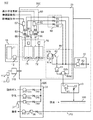
FIG. 1 shows a configuration example of a
取得部10は、被除去物が含まれている油田随伴水のような被処理水を取得する。例えば、取得部10は、セパレータ(図示せず)により、油井から産出される流体から随伴ガスおよび原油を除去した残りの油田随伴水を取得する。取得部10は、例えば、取得した被処理水を蓄える被処理水タンク11と送水ポンプ12とを有する。取得部10は、被処理水タンク11に蓄えられた被処理水を送水ポンプ12によって分離部20に送水する。
The
分離部20は、密閉された筐体内に貯蔵部60、凝集部70、回収部80及び還流部90を有し、被除去物を含む被処理水から被除去物を分離する。まず、取得部10から送られた被処理水は、凝集部70において、貯蔵部60から投入された凝集剤及び磁性体と撹拌される。凝集部70は、被処理水、凝集剤及び磁性体を撹拌することにより、磁性を有するフロックを生成する。凝集部70において生成されたフロックの少なくとも一部は、回収部80において回収され、被除去物排出部40に送られる。以上の手順により、分離部20は、被処理水から被除去物を分離することができる。分離部20の詳細な構成については後述する。
酸素除去部30は、分離部20を密閉する密閉容器500の内部に連通する排気管310及び給気管320と接続されている。酸素除去部30は、排気ポンプ31、排気バルブ32、給気ポンプ33b、給気ポンプ33c、給気バルブ34a、給気バルブ34b、給気バルブ34c、レギュレータ35及びガス濃度センサ36を有する。
The
酸素除去部30は、給気管320を介して気体を供給しながら、排気管310を介して密閉容器500の内部の気体を排気する。酸素除去部30は、外部から貯蔵部60に取り込まれる凝集剤及び磁性体に付着して分離部20に流入した酸素を除去する。この時、酸素除去部30は、必要に応じて設けられた排気ポンプ31によって吸引することで、密閉容器500の内部の酸素ガス濃度を効率よく下げることができる。酸素除去部30は、密閉容器500の内部の酸素濃度が50ppb以下になるまで酸素を除去することが好ましく、酸素濃度が10ppb以下になるまで酸素を除去することがさらに好ましい。
The
密閉容器500の内部から酸素を除去するために、酸素除去部30は、例えば、高圧ボンベ37に充填された窒素、二酸化炭素若しくはアルゴン等の不活性気体、又は油田随伴ガスなどの無酸素ガスを、レギュレータ35及び給気バルブ34aを介して密閉容器500に供給する。さらに、メンテナンス時など、酸素除去部30は、給気ポンプ33bにおいて加圧した空気を、給気バルブ34bを介して密閉容器500に供給することで、容器内の不活性気体を空気に置換してもよい。酸素除去部30は、セパレータで分離した随伴ガスを給気ポンプ33cにより加圧した後に、給気バルブ34cを介して密閉容器500に供給してもよい。
In order to remove oxygen from the inside of the
酸素除去部30は、不活性気体を分離部20に充填することにより、分離部20の内部の気圧を分離部20の外部の気圧よりも高い陽圧状態にすることが好ましい。例えば、分離部20の内部の気圧は、2パスカル以上50パスカル以下であることが好ましく、5パスカル以上10パスカル以下であることがさらに好ましい。分離部20の内部を陽圧状態にすることで、外部からの酸素の流入を防ぐことができる。
The
酸素を効率よく除去するために、排気管310及び給気管320は、密閉容器500において互いにできるだけ離れた位置に設けられていることが好ましい。例えば、排気管310及び給気管320は、密閉容器500の最も離れた2つの角の付近にそれぞれ設けられることが好ましい。分離装置100は、密閉容器500の内部の気体を撹拌するためのファンを有する撹拌部(図示せず)を有してもよい。分離装置100が撹拌部を有することにより、排気管310及び給気管320を近接させることができるとともに、比重が異なる複数の気体を無酸素ガスとして供給することができる。
In order to efficiently remove oxygen, it is preferable that the
以下、分離部20から酸素を除去するための手順を説明する。
まず、分離装置100の運転に先立ち、制御盤110を介して、分離装置100における各種センサ及び電磁式バルブのうち防爆仕様でないものに供給される電源を遮断する。次に、密閉容器500を密閉状態にした後に、排気バルブ32を開いて給気バルブ34a、給気バルブ34b及び給気バルブ34cを閉じて、撹拌部のファンにより密閉容器500内の気体を撹拌する。続いて、給気バルブ34aを開いて高圧ボンベ37から窒素を密閉容器500の内部に送ることで、密閉容器500の内部の酸素を含む空気を窒素に置換する。密閉容器500の内部の空気を窒素に置換した後に、各種のセンサ及び電磁式バルブに通電を開始することで、各種のセンサ及び電磁式バルブが防爆仕様でない場合であっても、爆発を防止することができる。Hereinafter, a procedure for removing oxygen from the
First, prior to the operation of the
次いで、排気バルブ32の後段に設けられたガス濃度センサ36において測定された酸素濃度が1%未満になった時点で給気バルブ34aを閉じて給気バルブ34cを開いて随伴ガスを密閉容器500の内部に導入することで、密閉容器500の内部の窒素を随伴ガスに置換する。ガス濃度センサ36を用いて、随伴ガスへの置換が完了したことを検出することができるが、簡易的に所定量(例えば密閉容器500の容積の約10倍)の随伴ガスを供給した時点で置換が完了したと判断してもよい。
Next, when the oxygen concentration measured by the
続いて、排気バルブ32を閉じて密閉容器500の内部の圧力を外気圧よりも高い状態に保持することで、分離部20を無酸素状態に保持することができる。上記の方法によれば、随伴ガス雰囲気下で分離部20を動作させることができるので、より地下に近い環境下でフロックの回収が可能になり、より確実に腐食性の発現を防止することができる。
Subsequently, the
なお、配線の接続端子などの導電部の腐食を防ぐために、制御盤110を密閉した状態で、レギュレータ112を介して、高圧ボンベ111に蓄えられた腐食性成分及び可燃性成分を含まない空気又は窒素若しくは二酸化炭素などの不活性気体を供給し、制御盤110の内部の気圧を外気圧よりも高い状態に保持することが好ましい。
In order to prevent corrosion of conductive parts such as connection terminals of the wiring, air that does not contain corrosive components and flammable components stored in the high-
被除去物排出部40は、排出ポンプ41及び排出バルブ42を有し、分離部20において分離された被除去物を外部に排出する。例えば、被除去物排出部40は、被処理水に含まれる油田随伴水とともに生産された原油を搬送するパイプライン300に対して被除去物を排出する。被除去物は、酸素が除去された状態の分離部20において被処理水から分離されるので酸素ガスと接触していない。したがって、被除去物がパイプライン300に混入してもパイプライン300は腐食しない。
The removal
処理水排出部50は、排出ポンプ51及び排出バルブ52を有し、分離部20において被除去物が分離された後の処理水を外部に排出する。例えば、分離装置100が海上にある場合には、処理水排出部50は海に処理水を排出する。処理水排出部50は、処理水を運搬する船舶等の移動体に排出してもよい。処理水排出部50は、排出した処理水の逆流を防ぐトラップをさらに有することが好ましい。
The treated
以上のとおり、酸素除去部30が分離部20の内部から酸素を除去することにより、分離部20においては、内部の酸素が除去された状態で被処理水から被除去物と処理水が分離されるので、分離された被除去物及び処理水には酸素が含まれない。したがって、分離部20で分離処理する被処理水に揮発性の油分が含まれていたとしても爆発の危険性がないので、防爆設備のコストを下げることができる他、防爆仕様となっていない多様なセンサ類を設備の制御に使用できる。また、被除去物に酸素が結合していないので、被除去物排出部40が被除去物をパイプライン300に排出したとしても、パイプライン300が腐食しない。
As described above, when the
[分離部20の構成例]
以下、分離部20の詳細な構成、及び、被除去物を分離する詳細な手順について説明する。
貯蔵部60は、被処理水に含まれている被除去物を凝集させる凝集剤および磁性体を貯蔵するタンクを有する。図1に示す例においては、貯蔵部60は、無機凝集剤タンク61、高分子凝集剤タンク62、磁性体撹拌槽63、高分子凝集剤撹拌槽64、ポンプ65、ポンプ66、ポンプ68及び新規磁性体タンク67を有する。[Configuration Example of Separation Unit 20]
Hereinafter, a detailed configuration of the
The
無機凝集剤タンク61は、例えばPAC(ポリ塩化アルミニウム)、硫酸第二鉄、塩化第二鉄、硫酸アルミニウム等の無機凝集剤を貯蔵する。高分子凝集剤タンク62は、例えばポリアクリルアミドのようなアニオン系の凝集剤を貯蔵する。高分子凝集剤タンク62に貯蔵された粉末の高分子凝集剤は、高分子凝集剤撹拌槽64で酸素を含まない水に溶解された後に、例えばポンプ66を用いて凝集部70中の第2凝集部72に投入されて、被処理水と撹拌される。無機凝集剤が液状の状態で供給される場合は、そのままの状態で計量手段(図示せず)により計量されてからポンプ68を用いて凝集部70中の第1凝集部71に投入され、被処理水と撹拌される。なお、無機凝集剤が粉末状の場合、高分子凝集剤と同様に酸素を含まない水に溶解された後、取得部10から導入された被処理水に混合される。
The
磁性体は、マグネタイト粒子に代表されるように、通常、新規のものは粉末状態で、ホッパー(図示せず)を通して系内に投入され、新規磁性体タンク67に蓄えられる。被除去物の除去に用いられた後に回収部80において回収された磁性体は、その回収部80の仕様によりさまざまな性状を呈すが、液状の場合、還流バルブ93を通して回収される。これらの磁性体は、磁性体撹拌槽63で、酸素を含まない水に分散され、第1凝集部71で、被処理水及び無機凝集剤とともに混合撹拌される。酸素を含まない水は、密閉容器500の外部から導入してもよいが、処理水を密閉容器内でリサイクルすることも可能である。
As typified by magnetite particles, a new magnetic material is normally put into a system through a hopper (not shown) in a powder state and stored in a new
凝集部70は、第1凝集部71及び第2凝集部72を有し、貯蔵部60から投入された凝集剤と取得部10から導入された被処理水とを撹拌することにより、被処理水に含まれている被除去物が凝集したフロックを生成する。具体的には、第1凝集部71には、取得部10から被処理水が導入されるとともに、無機凝集剤タンク61及び磁性体撹拌槽63のそれぞれから無機凝集剤及び磁性体が投入された後に撹拌される。第1凝集部71において被処理水、無機凝集剤及び磁性体が撹拌されることにより、表面が負に帯電した被除去物の表面電荷が無機凝集剤によって中和され、磁性体を含む凝集剤と被除去物とが凝集し、磁性を有するフロックが生成される。
The aggregating
第1凝集部71で形成されたフロックを含む一次処理水は、第2凝集部72に送られる。第2凝集部72には、高分子凝集剤撹拌槽64から高分子凝集剤が投入される。投入された高分子凝集剤は、第1凝集部71から導入された一次処理水と撹拌される。第2凝集部72には、回収磁性体を投入してもよい。
The primary treated water including the floc formed by the
高分子凝集剤撹拌槽64からの高分子凝集剤の投入量は、第1凝集部71に投入された無機凝集剤及び回収磁性体の量に応じて決定される。例えば、コンピュータにより、第1凝集部71に投入された無機凝集剤及び回収磁性体の量をモニタリングし、モニタリングにより得られた値に応じて、高分子凝集剤を投入するポンプ66を制御する。
The amount of the polymer flocculant charged from the polymer
第2凝集部72においては、第1凝集部71における撹拌速度よりも遅い速度で撹拌することにより、第1凝集部71からの一次処理水に含まれていた磁性フロックが成長し、より大きな磁性フロックを含む二次処理水が生成される。第2凝集部72が複数の槽を有し、複数回に渡って凝集処理を施すことにより、さらに大きな磁性フロックを生成してもよい。
In the
回収部80は、磁気分離部81、スクレーパ82、フロック移送ポンプ83及び磁性体回収部84を有する。回収部80は、磁性を有する回収体により磁性フロックを回収して被除去物排出部40に送る。
The
磁気分離部81は、磁気分離槽81a及び磁気ドラム81bを有する。磁気分離槽81aには、第2凝集部72で生成された磁性フロックを含む二次処理水が注入される。磁気ドラム81bは、磁石を内蔵しており、少なくとも一部が磁気分離槽81a内の二次処理水に浸されている。二次処理水が磁気ドラム81bに接触すると、磁石の磁気力によって、二次処理水内のフロックに含まれている磁性体が磁気ドラム81bに吸着される。
The magnetic separation unit 81 includes a
スクレーパ82は、磁気ドラム81bの回転に伴って磁気分離槽81aの外に出された磁性フロックを掻き取る。スクレーパ82は、例えばゴムにより形成された板であり、少なくとも一部が磁気ドラム81bの表面に接する。
The
フロック移送ポンプ83は、スクレーパ82によって掻き取られた磁性フロックを加速させて磁性体回収部84に送出する。磁性体回収部84は、フロック移送ポンプ83を介して磁性フロックが送り込まれる磁性体回収槽84aと、磁性体回収槽84aの内部で回転し、永久磁石を内蔵する磁気ドラム84bとを有する。フロック移送ポンプ83を介して磁性体回収槽84aに送られたフロックは、フロック移送ポンプ83により加速された状態で磁気ドラム84bの周辺を通過することにより生じるせん断力によって分解される。
The
分解されたフロックのうち、凝集部70における凝集に必要な磁力を有するフロックは磁気ドラム84bにより回収され、還流部90を介して磁性体撹拌槽63に送られる。例えば、磁性体回収部84は、所定の強度以上の磁力を帯びたフロックを選別して還流部90に送る。分解されたフロックのうち、磁気ドラム84bにより回収されなかったフロックは、汚泥として被除去物排出部40に送られる。磁気ドラム84bは、十分な強度の磁性を有するフロックを磁性体撹拌槽63に送るために、磁気ドラム81bよりも強い磁力を有する磁石を有することが好ましい。
Of the disassembled flocs, flocs having a magnetic force required for aggregation in the
回収部80は、磁性フロックが除去された二次処理水の一部を、還流部90を介して貯蔵部60に送り、残りの二次処理水を処理水排出部50に送る。回収部80は、例えば、貯蔵部60における凝集剤の溶解に必要な水量に応じた量の二次処理水を還流部90に送る。回収部80は、二次処理水の水質が、貯蔵部60における凝集剤の溶解又は凝集部70における凝集に必要な水質条件を満たす場合に、二次処理水を還流部90に送ってもよい。
The
還流部90は、磁性フロックが除去された二次処理水の少なくとも一部を、還流バルブ91及び還流バルブ92を介して無酸素状態で貯蔵部60に還流し、磁性体撹拌槽63及び高分子凝集剤撹拌槽64に送る。還流部90は、例えば、新規磁性体タンク67に貯蔵されている無機凝集剤の量、及び高分子凝集剤タンク62に貯蔵されている高分子凝集剤の量のいずれかに基づいて、貯蔵部60に還流する二次処理水の量を制御する。
The
また、還流部90は、磁性体回収部84が回収した磁性体を含むフロックを、還流バルブ93を介して磁性体撹拌槽63に送る。還流部90は、例えば、新規磁性体タンク67に貯蔵されている新規磁性体の量に基づいて、貯蔵部60に還流するフロックの量を制御する。
In addition, the
分離部20の内部の酸素濃度が所定の値よりも小さくなっているので、二次処理水が還流部90を介して無機凝集剤タンク61及び高分子凝集剤タンク62に注入されるまでの間に、二次処理水が酸素に触れることがない。したがって、貯蔵部60において二次処理水を用いた場合であっても、凝集部70に酸素が入らない。同様に、還流部90が磁性体撹拌槽63に送った回収磁性体も酸素を含まないので、回収磁性体が凝集部70に投入された場合であっても、凝集部70には酸素が入らない。
Since the oxygen concentration inside the
[コンピュータによる制御]
なお、分離装置100は、取得部10、分離部20、酸素除去部30、被除去物排出部40及び処理水排出部50を制御するコンピュータやシーケンサ等の制御手段を有してもよい。例えば、コンピュータが記憶媒体に記憶されたプログラムを実行することにより、被除去物を含む被処理水を取得する工程、被処理水から被除去物を分離する工程、分離部20から酸素を除去する工程、分離部20において分離された被除去物を排出する工程、及び、被処理水から被除去物が分離されて残る処理水を排出する工程を実行することができる。[Control by computer]
The
以上のとおり、第1の実施形態に係る分離装置100においては、被処理水から被除去物を分離する分離部20から酸素が除去されているので、分離部20における爆発を防ぐことができる。また、分離部20において被処理水から分離された処理水には酸素が含まれないので、凝集剤を溶かす水として処理水を再利用することができる。また、被除去物にも酸素が含まれないので、パイプライン300を用いて排出することができる。
As described above, in the
<第2の実施形態>
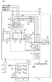
図2は、第2の実施形態に係る分離装置100の構成例を示す。第1の実施形態に係る分離装置100においては、分離部20が密閉され、酸素除去部30は分離部20のみから酸素を除去した。これに対して、図2に示す分離装置100においては、取得部10、分離部20及び被除去物排出部40を含む筐体が密閉され、酸素除去部30は、取得部10、分離部20及び被除去物排出部40を含む密閉空間から酸素を除去する。<Second Embodiment>
FIG. 2 shows a configuration example of the
第1の実施形態と同様に、取得部10は、被除去物が含まれている油田随伴水を被処理水として取得する。取得部10は、セパレータ(図示せず)により、油井から産出される流体から随伴ガスおよび原油を除去した残りの随伴水を、被処理水として蓄える被処理水タンク11と送水ポンプ12とを有する。取得部10は、被処理水タンク11に蓄えられた被処理水を送水ポンプ12によって分離部20に送水する。
Similar to the first embodiment, the
酸素除去部30が取得部10を含む密閉空間から酸素を除去することにより、被除去物を分離する前の被処理水が酸素に触れないので、分離部20への酸素の流入を防止できる。また、酸素除去部30が被除去物排出部40を含む密閉空間から酸素を除去することにより、分離部20において被除去物が分離されてからパイプライン300に送られるまでの間に酸素に触れないので、酸素と結合した被除去物がパイプライン300に入ることを防止できる。
Since the
<第3の実施形態>
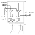
図3は、第3の実施形態に係る貯蔵部60及び凝集部70の周辺の構成例を示す。図3における高分子凝集剤タンク62及び新規磁性体タンク67には、レギュレータ121並びにバルブ122及びバルブ123を介して、高圧ボンベ120から不活性気体が供給される。高分子凝集剤タンク62及び新規磁性体タンク67に外部から新規の凝集剤を投入するたびに不活性気体を供給し、凝集剤の投入時に流入した酸素を含む空気を除去することにより、分離部20に酸素が流入することを防ぐことができる。<Third Embodiment>
FIG. 3 shows a configuration example around the
<第4の実施形態>
上記の実施形態に係る分離装置100においては、新規磁性体、無機凝集剤及び回収磁性体が第1凝集部71に投入され、高分子凝集剤及び回収磁性体が第2凝集部72に投入されていた。これに対して、これらの凝集剤及び磁性体は、第1凝集部71及び第2凝集部72のいずれに投入されてもよい。例えば、コンピュータがポンプを制御することにより、回収磁性体の量を監視し、回収磁性体の量に応じた量の新規磁性体を第1凝集部71及び第2凝集部72のいずれかに投入してもよい。<Fourth Embodiment>
In the
以上、本発明を実施の形態を用いて説明したが、本発明の技術的範囲は上記実施の形態に記載の範囲には限定されない。上記実施の形態に、多様な変更又は改良を加えることが可能であることが当業者に明らかである。例えば、上記の実施形態においては、磁性粒子を含む凝集剤を用いて磁性フロックを生成することにより被除去物を除去したが、他の方法によって被除去物を除去する構成においても同等の作用効果を奏し、そのような変更又は改良を加えた形態も本発明の技術的範囲に含まれ得ることが、請求の範囲の記載から明らかである。 As mentioned above, although this invention was demonstrated using embodiment, the technical scope of this invention is not limited to the range as described in the said embodiment. It will be apparent to those skilled in the art that various modifications or improvements can be added to the above embodiment. For example, in the above embodiment, the object to be removed is removed by generating a magnetic floc using an aggregating agent containing magnetic particles, but the same effect can be obtained in a configuration in which the object to be removed is removed by another method. It is apparent from the description of the scope of the claims that the embodiments with the above-described modifications and improvements can be included in the technical scope of the present invention.
10・・・取得部、11・・・被処理水タンク、12・・・送水ポンプ、20・・・分離部、30・・・酸素除去部、31・・・排気ポンプ、32・・・排気バルブ、33・・・給気ポンプ、34・・・給気バルブ、35・・・レギュレータ、36・・・ガス濃度センサ、37・・・高圧ボンベ、40・・・被除去物排出部、41・・・排出ポンプ、42・・・排出バルブ、50・・・処理水排出部、51・・・排出ポンプ、52・・・排出バルブ、60・・・貯蔵部、61・・・無機凝集剤タンク、62・・・高分子凝集剤タンク、63・・・磁性体撹拌槽、64・・・高分子凝集剤撹拌槽、65・・・計量部、66・・・計量部、67・・・新規磁性体タンク、70・・・凝集部、71・・・第1凝集部、72・・・第2凝集部、80・・・回収部、81・・・磁気分離部、81a・・・磁気分離槽、81b・・・磁気ドラム、82・・・スクレーパ、83・・・フロック移送ポンプ、84・・・磁性体回収部、84a・・・磁性体回収槽、84b・・・磁気ドラム、90・・・還流部、91・・・還流バルブ、92・・・還流バルブ、93・・・還流バルブ、100・・・分離装置、110・・・制御盤、111・・・高圧ボンベ、112・・・レギュレータ、120・・・高圧ボンベ、121・・・レギュレータ、122・・・バルブ、123・・・バルブ、200・・・パイプライン
DESCRIPTION OF
Claims (5)
前記油田随伴水を被処理水として、前記セパレータから取得する取得部と、
前記被処理水から油分を分離する分離部と、
少なくとも前記分離部を密閉する密閉容器と、
前記分離部の内部の酸素を除去する酸素除去部と、
前記被処理水から分離された前記油分を排出する被除去物排出部と、
前記被処理水から前記油分が分離されて残る処理水を排出する処理水排出部と
を備え、
前記酸素除去部は、
前記油田随伴ガスが前記セパレータから、不活性気体により内部の酸素が置換された前記密閉容器内の前記分離部に供給されるように、前記セパレータに接続されているとともに、前記密閉容器の内部に連通し、無酸素性の前記油田随伴ガスを前記密閉容器に供給する給気管と、
前記密閉容器の内部に連通して、前記密閉容器の内部の酸素を排気する排気管と、
を有する分離装置。 A separator that is provided in an oil field and separates oil field associated gas and oil field associated water generated accompanying the crude oil produced in the oil field;
The oil field accompanying water as treated water, an acquisition unit that acquires from the separator ;
A separation unit for separating oil from the treated water;
A sealed container for sealing at least the separation part;
An oxygen removing unit for removing oxygen inside the separating unit;
To-be-removed object discharge part which discharges the oil separated from the treated water,
A treated water discharge section for discharging treated water remaining after the oil component is separated from the treated water ,
The oxygen removing unit is
The oil field associated gas is connected to the separator so that the gas accompanying the oil field is supplied from the separator to the separation unit in the sealed container in which oxygen is replaced by an inert gas. An air supply pipe that communicates the oxygen-free gas associated with the oil field to the sealed container;
An exhaust pipe communicating with the inside of the sealed container and exhausting oxygen inside the sealed container;
That having a separation device.
前記被処理水に含まれる前記油分を凝集させる凝集剤を貯蔵する貯蔵部と、
前記凝集剤と前記被処理水とを撹拌することにより、前記油分が凝集した凝集物を生成する凝集部と、
前記凝集物を回収して前記被除去物排出部に送る回収部と
を有する請求項1に記載の分離装置。 The separation unit is
A storage unit for storing a flocculant for aggregating the oil contained in the water to be treated;
An agglomeration part for producing an agglomerate in which the oil is agglomerated by stirring the flocculant and the water to be treated;
The separation apparatus according to claim 1, further comprising: a collection unit that collects the aggregate and sends the aggregate to the removal object discharge unit.
前記貯蔵部は、前記還流部によって還流された前記処理水に前記凝集剤を溶解させる請求項2に記載の分離装置。 A reflux part for refluxing at least part of the treated water to the storage part in an oxygen-free state;
The separation apparatus according to claim 2, wherein the storage unit dissolves the flocculant in the treated water refluxed by the reflux unit.
前記被除去物排出部は、前記原油を搬送するパイプラインに対して前記油分を排出する請求項1から3のいずれか一項に記載の分離装置。 The acquisition unit acquires oil field associated water produced together with crude oil as the treated water,
The objects of removal discharging unit, the separation device according to any one of claims 1 to 3 for discharging the oil with respect to the pipeline which conveys the crude oil.
前記被処理水から油分を分離する工程と、
前記油分を分離する工程を実行する分離部を密閉する密閉容器から酸素を除去する酸素除去工程と、
前記被処理水から分離された前記油分を排出する工程と、
前記被処理水から前記油分が分離されて残る処理水を排出する工程と
を備え、
前記酸素除去工程は、
前記密閉容器に不活性気体を供給することにより、前記密閉容器の内部の酸素を除去する第1酸素除去工程と、
前記第1酸素除去工程の後に、前記セパレータにおいて分離された前記油田随伴ガスを前記密閉容器に供給する第2酸素除去工程と、
を有する分離方法。
Obtaining the oil field associated water as treated water from a separator that is provided in the oil field and separates the oil field associated gas and the oil field associated water generated accompanying the crude oil produced in the oil field ;
Separating oil from the treated water;
An oxygen removing step of removing oxygen from a sealed container that seals a separation unit that performs the step of separating the oil; and
Discharging the oil separated from the treated water;
And a step of discharging the treated water remaining after the oil component is separated from the treated water ,
The oxygen removal step includes
A first oxygen removing step of removing oxygen inside the sealed container by supplying an inert gas to the sealed container;
After the first oxygen removal step, a second oxygen removal step of supplying the oil field associated gas separated in the separator to the sealed container ;
A separation method.
Applications Claiming Priority (3)
| Application Number | Priority Date | Filing Date | Title |
|---|---|---|---|
| JP2012259432 | 2012-11-28 | ||
| JP2012259432 | 2012-11-28 | ||
| PCT/JP2013/081468 WO2014084128A1 (en) | 2012-11-28 | 2013-11-22 | Separation device and separation method |
Publications (2)
| Publication Number | Publication Date |
|---|---|
| JPWO2014084128A1 JPWO2014084128A1 (en) | 2017-01-05 |
| JP6139563B2 true JP6139563B2 (en) | 2017-05-31 |
Family
ID=50827766
Family Applications (1)
| Application Number | Title | Priority Date | Filing Date |
|---|---|---|---|
| JP2014550156A Expired - Fee Related JP6139563B2 (en) | 2012-11-28 | 2013-11-22 | Separation apparatus and separation method |
Country Status (5)
| Country | Link |
|---|---|
| US (1) | US20150259229A1 (en) |
| EP (1) | EP2927195B1 (en) |
| JP (1) | JP6139563B2 (en) |
| NO (1) | NO2927195T3 (en) |
| WO (1) | WO2014084128A1 (en) |
Families Citing this family (3)
| Publication number | Priority date | Publication date | Assignee | Title |
|---|---|---|---|---|
| US10239020B2 (en) * | 2015-02-09 | 2019-03-26 | Sumitomo Electric Industries, Ltd. | Water treatment system and water treatment method |
| JP2017159291A (en) * | 2016-03-07 | 2017-09-14 | 伯東株式会社 | Processing method for crude oil-containing waste liquid and processing equipment for crude oil-containing waste liquid |
| CN111686604A (en) * | 2020-06-12 | 2020-09-22 | 靳双玲 | Coating mixing device with inner wall self-cleaning function |
Family Cites Families (12)
| Publication number | Priority date | Publication date | Assignee | Title |
|---|---|---|---|---|
| US3803033A (en) * | 1971-12-13 | 1974-04-09 | Awt Systems Inc | Process for removal of organic contaminants from a fluid stream |
| US3994802A (en) * | 1975-04-16 | 1976-11-30 | Air Products And Chemicals, Inc. | Removal of BOD and nitrogenous pollutants from wastewaters |
| JPS63274408A (en) * | 1987-05-07 | 1988-11-11 | Mitsubishi Heavy Ind Ltd | Separator control apparatus |
| GB0001649D0 (en) * | 2000-01-26 | 2000-12-20 | British Aerospace | A fuel inerting system |
| US7243721B2 (en) * | 2001-06-12 | 2007-07-17 | Hydrotreat, Inc. | Methods and apparatus for heating oil production reservoirs |
| JP4239781B2 (en) * | 2003-10-14 | 2009-03-18 | 株式会社日立プラントテクノロジー | Product processing system |
| US8470172B2 (en) * | 2007-01-09 | 2013-06-25 | Siemens Industry, Inc. | System for enhancing a wastewater treatment process |
| US20110036771A1 (en) * | 2007-01-09 | 2011-02-17 | Steven Woodard | Ballasted anaerobic system and method for treating wastewater |
| US7597144B2 (en) * | 2007-08-27 | 2009-10-06 | Hpd, Llc | Process for recovering heavy oil utilizing one or more membranes |
| US20100230366A1 (en) * | 2008-09-25 | 2010-09-16 | Otv Sa | Seawater treatment method for the production of injection water for undersea oil drilling and corresponding installation |
| JP5831736B2 (en) * | 2010-08-19 | 2015-12-09 | 清水建設株式会社 | Pressure floating separator |
| JP5422516B2 (en) * | 2010-08-23 | 2014-02-19 | 株式会社日立製作所 | Aggregation magnetic separator |
-
2013
- 2013-11-22 JP JP2014550156A patent/JP6139563B2/en not_active Expired - Fee Related
- 2013-11-22 WO PCT/JP2013/081468 patent/WO2014084128A1/en not_active Ceased
- 2013-11-22 NO NO13859233A patent/NO2927195T3/no unknown
- 2013-11-22 EP EP13859233.2A patent/EP2927195B1/en not_active Not-in-force
-
2015
- 2015-05-27 US US14/723,369 patent/US20150259229A1/en not_active Abandoned
Also Published As
| Publication number | Publication date |
|---|---|
| NO2927195T3 (en) | 2018-07-28 |
| US20150259229A1 (en) | 2015-09-17 |
| EP2927195A1 (en) | 2015-10-07 |
| EP2927195A4 (en) | 2015-10-07 |
| JPWO2014084128A1 (en) | 2017-01-05 |
| WO2014084128A1 (en) | 2014-06-05 |
| EP2927195B1 (en) | 2018-02-28 |
Similar Documents
| Publication | Publication Date | Title |
|---|---|---|
| JP6139563B2 (en) | Separation apparatus and separation method | |
| US20130255941A1 (en) | Mobile water treatment and method | |
| CN114772623A (en) | A kind of method that utilizes aluminum ash to continuously produce polyaluminum chloride | |
| JP5955043B2 (en) | Wet paint booth circulating water paint mist treatment agent and wet paint booth circulating water recovery device | |
| CA2789207C (en) | Method and system for decontaminating sand | |
| RU2553100C2 (en) | Gravity-magnetic separator | |
| JP2010207755A (en) | Apparatus for treating fluorine-containing water | |
| US10391532B2 (en) | System and method for treatment of contaminated sediments or soils using free radical chemical reaction and phase separation processes | |
| CN208218927U (en) | The recycling separation system of heavy metal in a kind of solid waste | |
| AU2017211155A1 (en) | Apparatus and process for flocculation of solids fractions of a solid-liquid mixture | |
| JP2014079752A (en) | Treatment method and treatment apparatus of an effluent | |
| CN108435726A (en) | A kind of cleaning method and system of mercurous oil sump | |
| JP2012233766A (en) | Method for removing radioactive substance in radioactive effluent and system for removing radioactive substance in radioactive effluent | |
| Sun et al. | Design and Application of Rapid Dewatering for Tailings Containing Sodium Silicate: Laboratory and Industrial Test Results | |
| KR101573624B1 (en) | Dredged processing device using a magnetic field | |
| JP6458635B2 (en) | Contaminated soil cleaning equipment and contaminated soil cleaning method | |
| KR20200041881A (en) | Treatment of liquid streams containing high concentrations of solids using ballast-type clarification | |
| CN111792759A (en) | Sewage sludge conditioning process and system based on carbon source recycling | |
| JP5789835B2 (en) | Method and system for removing radioactive material | |
| CN201361394Y (en) | Harmless treatment device of solid hazardous wastes | |
| WO2013136429A1 (en) | Coating material mist treatment agent for wet-coating-booth circulating water and device for recovering wet-coating-booth circulating water | |
| KR100880251B1 (en) | High concentration organic wastewater treatment device | |
| JP6446220B2 (en) | Jellyfish waste reduction method and jellyfish waste reduction device | |
| CN105268308B (en) | In a kind of ore pulp desulfurization and clear liquid reclamation set and method | |
| US20190351469A1 (en) | System and method for treatment of contaminated sediments using free radical chemical reaction and phase separation processes |
Legal Events
| Date | Code | Title | Description |
|---|---|---|---|
| A131 | Notification of reasons for refusal |
Free format text: JAPANESE INTERMEDIATE CODE: A131 Effective date: 20170131 |
|
| A521 | Request for written amendment filed |
Free format text: JAPANESE INTERMEDIATE CODE: A523 Effective date: 20170307 |
|
| TRDD | Decision of grant or rejection written | ||
| A01 | Written decision to grant a patent or to grant a registration (utility model) |
Free format text: JAPANESE INTERMEDIATE CODE: A01 Effective date: 20170404 |
|
| A61 | First payment of annual fees (during grant procedure) |
Free format text: JAPANESE INTERMEDIATE CODE: A61 Effective date: 20170427 |
|
| R150 | Certificate of patent or registration of utility model |
Ref document number: 6139563 Country of ref document: JP Free format text: JAPANESE INTERMEDIATE CODE: R150 |
|
| LAPS | Cancellation because of no payment of annual fees |