JP6139532B2 - Cap assembly for drug delivery device - Google Patents
Cap assembly for drug delivery device Download PDFInfo
- Publication number
- JP6139532B2 JP6139532B2 JP2014530264A JP2014530264A JP6139532B2 JP 6139532 B2 JP6139532 B2 JP 6139532B2 JP 2014530264 A JP2014530264 A JP 2014530264A JP 2014530264 A JP2014530264 A JP 2014530264A JP 6139532 B2 JP6139532 B2 JP 6139532B2
- Authority
- JP
- Japan
- Prior art keywords
- cap body
- drug delivery
- delivery device
- cartridge holder
- cap
- Prior art date
- Legal status (The legal status is an assumption and is not a legal conclusion. Google has not performed a legal analysis and makes no representation as to the accuracy of the status listed.)
- Expired - Fee Related
Links
- 238000012377 drug delivery Methods 0.000 title claims description 78
- 239000003814 drug Substances 0.000 claims description 12
- 230000007246 mechanism Effects 0.000 claims description 9
- 229940079593 drug Drugs 0.000 claims description 8
- 238000006073 displacement reaction Methods 0.000 claims description 7
- 238000000034 method Methods 0.000 claims description 5
- 230000003213 activating effect Effects 0.000 claims 1
- JUFFVKRROAPVBI-PVOYSMBESA-N chembl1210015 Chemical compound C([C@@H](C(=O)N[C@@H]([C@@H](C)CC)C(=O)N[C@@H](CCC(O)=O)C(=O)N[C@@H](CC=1C2=CC=CC=C2NC=1)C(=O)N[C@@H](CC(C)C)C(=O)N[C@@H](CCCCN)C(=O)N[C@@H](CC(=O)N[C@H]1[C@@H]([C@@H](O)[C@H](O[C@H]2[C@@H]([C@@H](O)[C@@H](O)[C@@H](CO[C@]3(O[C@@H](C[C@H](O)[C@H](O)CO)[C@H](NC(C)=O)[C@@H](O)C3)C(O)=O)O2)O)[C@@H](CO)O1)NC(C)=O)C(=O)NCC(=O)NCC(=O)N1[C@@H](CCC1)C(=O)N[C@@H](CO)C(=O)N[C@@H](CO)C(=O)NCC(=O)N[C@@H](C)C(=O)N1[C@@H](CCC1)C(=O)N1[C@@H](CCC1)C(=O)N1[C@@H](CCC1)C(=O)N[C@@H](CO)C(N)=O)NC(=O)[C@H](CC(C)C)NC(=O)[C@H](CCCNC(N)=N)NC(=O)[C@@H](NC(=O)[C@H](C)NC(=O)[C@H](CCC(O)=O)NC(=O)[C@H](CCC(O)=O)NC(=O)[C@H](CCC(O)=O)NC(=O)[C@H](CCSC)NC(=O)[C@H](CCC(N)=O)NC(=O)[C@H](CCCCN)NC(=O)[C@H](CO)NC(=O)[C@H](CC(C)C)NC(=O)[C@H](CC(O)=O)NC(=O)[C@H](CO)NC(=O)[C@@H](NC(=O)[C@H](CC=1C=CC=CC=1)NC(=O)[C@@H](NC(=O)CNC(=O)[C@H](CCC(O)=O)NC(=O)CNC(=O)[C@@H](N)CC=1NC=NC=1)[C@@H](C)O)[C@@H](C)O)C(C)C)C1=CC=CC=C1 JUFFVKRROAPVBI-PVOYSMBESA-N 0.000 description 83
- 108010011459 Exenatide Proteins 0.000 description 49
- 229960001519 exenatide Drugs 0.000 description 49
- 101000976075 Homo sapiens Insulin Proteins 0.000 description 22
- PBGKTOXHQIOBKM-FHFVDXKLSA-N insulin (human) Chemical compound C([C@@H](C(=O)N[C@@H](CC(C)C)C(=O)N[C@H]1CSSC[C@H]2C(=O)N[C@H](C(=O)N[C@@H](CO)C(=O)N[C@H](C(=O)N[C@H](C(N[C@@H](CO)C(=O)N[C@@H](CC(C)C)C(=O)N[C@@H](CC=3C=CC(O)=CC=3)C(=O)N[C@@H](CCC(N)=O)C(=O)N[C@@H](CC(C)C)C(=O)N[C@@H](CCC(O)=O)C(=O)N[C@@H](CC(N)=O)C(=O)N[C@@H](CC=3C=CC(O)=CC=3)C(=O)N[C@@H](CSSC[C@H](NC(=O)[C@H](C(C)C)NC(=O)[C@H](CC(C)C)NC(=O)[C@H](CC=3C=CC(O)=CC=3)NC(=O)[C@H](CC(C)C)NC(=O)[C@H](C)NC(=O)[C@H](CCC(O)=O)NC(=O)[C@H](C(C)C)NC(=O)[C@H](CC(C)C)NC(=O)[C@H](CC=3NC=NC=3)NC(=O)[C@H](CO)NC(=O)CNC1=O)C(=O)NCC(=O)N[C@@H](CCC(O)=O)C(=O)N[C@@H](CCCNC(N)=N)C(=O)NCC(=O)N[C@@H](CC=1C=CC=CC=1)C(=O)N[C@@H](CC=1C=CC=CC=1)C(=O)N[C@@H](CC=1C=CC(O)=CC=1)C(=O)N[C@@H]([C@@H](C)O)C(=O)N1[C@@H](CCC1)C(=O)N[C@@H](CCCCN)C(=O)N[C@@H]([C@@H](C)O)C(O)=O)C(=O)N[C@@H](CC(N)=O)C(O)=O)=O)CSSC[C@@H](C(N2)=O)NC(=O)[C@H](CCC(N)=O)NC(=O)[C@H](CCC(O)=O)NC(=O)[C@H](C(C)C)NC(=O)[C@@H](NC(=O)CN)[C@@H](C)CC)[C@@H](C)CC)[C@@H](C)O)NC(=O)[C@H](CCC(N)=O)NC(=O)[C@H](CC(N)=O)NC(=O)[C@@H](NC(=O)[C@@H](N)CC=1C=CC=CC=1)C(C)C)C1=CN=CN1 PBGKTOXHQIOBKM-FHFVDXKLSA-N 0.000 description 21
- 239000012634 fragment Substances 0.000 description 10
- 235000001014 amino acid Nutrition 0.000 description 9
- 150000001413 amino acids Chemical class 0.000 description 9
- 239000000427 antigen Substances 0.000 description 7
- 102000036639 antigens Human genes 0.000 description 7
- 108091007433 antigens Proteins 0.000 description 7
- 150000001875 compounds Chemical class 0.000 description 7
- 150000003839 salts Chemical class 0.000 description 7
- -1 Carboxyheptadecanoyl Chemical group 0.000 description 5
- 108090000765 processed proteins & peptides Proteins 0.000 description 5
- 108060003951 Immunoglobulin Proteins 0.000 description 4
- 102000018358 immunoglobulin Human genes 0.000 description 4
- 108010047041 Complementarity Determining Regions Proteins 0.000 description 3
- 208000002249 Diabetes Complications Diseases 0.000 description 3
- 210000003719 b-lymphocyte Anatomy 0.000 description 3
- 150000004676 glycans Chemical class 0.000 description 3
- 238000002347 injection Methods 0.000 description 3
- 239000007924 injection Substances 0.000 description 3
- 239000007788 liquid Substances 0.000 description 3
- 239000003055 low molecular weight heparin Substances 0.000 description 3
- 229940127215 low-molecular weight heparin Drugs 0.000 description 3
- 229920001282 polysaccharide Polymers 0.000 description 3
- 239000005017 polysaccharide Substances 0.000 description 3
- 230000001681 protective effect Effects 0.000 description 3
- 208000004476 Acute Coronary Syndrome Diseases 0.000 description 2
- 206010012689 Diabetic retinopathy Diseases 0.000 description 2
- 208000005189 Embolism Diseases 0.000 description 2
- 108010088406 Glucagon-Like Peptides Proteins 0.000 description 2
- 102000006771 Gonadotropins Human genes 0.000 description 2
- 108010086677 Gonadotropins Proteins 0.000 description 2
- HTTJABKRGRZYRN-UHFFFAOYSA-N Heparin Chemical compound OC1C(NC(=O)C)C(O)OC(COS(O)(=O)=O)C1OC1C(OS(O)(=O)=O)C(O)C(OC2C(C(OS(O)(=O)=O)C(OC3C(C(O)C(O)C(O3)C(O)=O)OS(O)(=O)=O)C(CO)O2)NS(O)(=O)=O)C(C(O)=O)O1 HTTJABKRGRZYRN-UHFFFAOYSA-N 0.000 description 2
- 102000002265 Human Growth Hormone Human genes 0.000 description 2
- 108010000521 Human Growth Hormone Proteins 0.000 description 2
- 239000000854 Human Growth Hormone Substances 0.000 description 2
- 208000001435 Thromboembolism Diseases 0.000 description 2
- 239000002253 acid Substances 0.000 description 2
- 150000001447 alkali salts Chemical class 0.000 description 2
- 229910052784 alkaline earth metal Inorganic materials 0.000 description 2
- 239000002585 base Substances 0.000 description 2
- 125000000151 cysteine group Chemical group N[C@@H](CS)C(=O)* 0.000 description 2
- 206010012601 diabetes mellitus Diseases 0.000 description 2
- 230000009977 dual effect Effects 0.000 description 2
- 108010015174 exendin 3 Proteins 0.000 description 2
- LMHMJYMCGJNXRS-IOPUOMRJSA-N exendin-3 Chemical compound C([C@@H](C(=O)N[C@@H]([C@@H](C)CC)C(=O)N[C@@H](CCC(O)=O)C(=O)N[C@@H](CC=1C2=CC=CC=C2NC=1)C(=O)N[C@@H](CC(C)C)C(=O)N[C@@H](CCCCN)C(=O)N[C@@H](CC(N)=O)C(=O)NCC(=O)NCC(=O)N1[C@@H](CCC1)C(=O)N[C@@H](CO)C(=O)N[C@@H](CO)C(=O)NCC(=O)N[C@@H](C)C(=O)N1[C@@H](CCC1)C(=O)N1[C@@H](CCC1)C(=O)N1[C@@H](CCC1)C(=O)N[C@@H](CO)C(N)=O)NC(=O)[C@H](CC(C)C)NC(=O)[C@H](CCCNC(N)=N)NC(=O)[C@@H](NC(=O)[C@H](C)NC(=O)[C@H](CCC(O)=O)NC(=O)[C@H](CCC(O)=O)NC(=O)[C@H](CCC(O)=O)NC(=O)[C@H](CCSC)NC(=O)[C@H](CCC(N)=O)NC(=O)[C@H](CCCCN)NC(=O)[C@H](CO)NC(=O)[C@H](CC(C)C)NC(=O)[C@H](CC(O)=O)NC(=O)[C@H](CO)NC(=O)[C@@H](NC(=O)[C@H](CC=1C=CC=CC=1)NC(=O)[C@@H](NC(=O)CNC(=O)[C@H](CC(O)=O)NC(=O)[C@H](CO)NC(=O)[C@@H](N)CC=1N=CNC=1)[C@H](C)O)[C@H](C)O)C(C)C)C1=CC=CC=C1 LMHMJYMCGJNXRS-IOPUOMRJSA-N 0.000 description 2
- 239000002622 gonadotropin Substances 0.000 description 2
- 229940088597 hormone Drugs 0.000 description 2
- 239000005556 hormone Substances 0.000 description 2
- 229940072221 immunoglobulins Drugs 0.000 description 2
- 238000007689 inspection Methods 0.000 description 2
- NOESYZHRGYRDHS-UHFFFAOYSA-N insulin Chemical class N1C(=O)C(NC(=O)C(CCC(N)=O)NC(=O)C(CCC(O)=O)NC(=O)C(C(C)C)NC(=O)C(NC(=O)CN)C(C)CC)CSSCC(C(NC(CO)C(=O)NC(CC(C)C)C(=O)NC(CC=2C=CC(O)=CC=2)C(=O)NC(CCC(N)=O)C(=O)NC(CC(C)C)C(=O)NC(CCC(O)=O)C(=O)NC(CC(N)=O)C(=O)NC(CC=2C=CC(O)=CC=2)C(=O)NC(CSSCC(NC(=O)C(C(C)C)NC(=O)C(CC(C)C)NC(=O)C(CC=2C=CC(O)=CC=2)NC(=O)C(CC(C)C)NC(=O)C(C)NC(=O)C(CCC(O)=O)NC(=O)C(C(C)C)NC(=O)C(CC(C)C)NC(=O)C(CC=2NC=NC=2)NC(=O)C(CO)NC(=O)CNC2=O)C(=O)NCC(=O)NC(CCC(O)=O)C(=O)NC(CCCNC(N)=N)C(=O)NCC(=O)NC(CC=3C=CC=CC=3)C(=O)NC(CC=3C=CC=CC=3)C(=O)NC(CC=3C=CC(O)=CC=3)C(=O)NC(C(C)O)C(=O)N3C(CCC3)C(=O)NC(CCCCN)C(=O)NC(C)C(O)=O)C(=O)NC(CC(N)=O)C(O)=O)=O)NC(=O)C(C(C)CC)NC(=O)C(CO)NC(=O)C(C(C)O)NC(=O)C1CSSCC2NC(=O)C(CC(C)C)NC(=O)C(NC(=O)C(CCC(N)=O)NC(=O)C(CC(N)=O)NC(=O)C(NC(=O)C(N)CC=1C=CC=CC=1)C(C)C)CC1=CN=CN1 NOESYZHRGYRDHS-UHFFFAOYSA-N 0.000 description 2
- 238000004519 manufacturing process Methods 0.000 description 2
- 239000000203 mixture Substances 0.000 description 2
- 239000000178 monomer Substances 0.000 description 2
- 230000002265 prevention Effects 0.000 description 2
- 102000004196 processed proteins & peptides Human genes 0.000 description 2
- 239000011734 sodium Substances 0.000 description 2
- 239000012453 solvate Substances 0.000 description 2
- 229960004532 somatropin Drugs 0.000 description 2
- KIUKXJAPPMFGSW-DNGZLQJQSA-N (2S,3S,4S,5R,6R)-6-[(2S,3R,4R,5S,6R)-3-Acetamido-2-[(2S,3S,4R,5R,6R)-6-[(2R,3R,4R,5S,6R)-3-acetamido-2,5-dihydroxy-6-(hydroxymethyl)oxan-4-yl]oxy-2-carboxy-4,5-dihydroxyoxan-3-yl]oxy-5-hydroxy-6-(hydroxymethyl)oxan-4-yl]oxy-3,4,5-trihydroxyoxane-2-carboxylic acid Chemical compound CC(=O)N[C@H]1[C@H](O)O[C@H](CO)[C@@H](O)[C@@H]1O[C@H]1[C@H](O)[C@@H](O)[C@H](O[C@H]2[C@@H]([C@@H](O[C@H]3[C@@H]([C@@H](O)[C@H](O)[C@H](O3)C(O)=O)O)[C@H](O)[C@@H](CO)O2)NC(C)=O)[C@@H](C(O)=O)O1 KIUKXJAPPMFGSW-DNGZLQJQSA-N 0.000 description 1
- 125000004169 (C1-C6) alkyl group Chemical group 0.000 description 1
- 108091032973 (ribonucleotides)n+m Proteins 0.000 description 1
- 208000035285 Allergic Seasonal Rhinitis Diseases 0.000 description 1
- 206010002383 Angina Pectoris Diseases 0.000 description 1
- 201000001320 Atherosclerosis Diseases 0.000 description 1
- 108010017384 Blood Proteins Proteins 0.000 description 1
- 102000004506 Blood Proteins Human genes 0.000 description 1
- 108010037003 Buserelin Proteins 0.000 description 1
- 125000000882 C2-C6 alkenyl group Chemical group 0.000 description 1
- 125000000041 C6-C10 aryl group Chemical group 0.000 description 1
- 108010041986 DNA Vaccines Proteins 0.000 description 1
- 108010000437 Deamino Arginine Vasopressin Proteins 0.000 description 1
- 206010012655 Diabetic complications Diseases 0.000 description 1
- 108090000790 Enzymes Proteins 0.000 description 1
- 102000004190 Enzymes Human genes 0.000 description 1
- 102000003886 Glycoproteins Human genes 0.000 description 1
- 108090000288 Glycoproteins Proteins 0.000 description 1
- 102400000932 Gonadoliberin-1 Human genes 0.000 description 1
- 108010069236 Goserelin Proteins 0.000 description 1
- BLCLNMBMMGCOAS-URPVMXJPSA-N Goserelin Chemical compound C([C@@H](C(=O)N[C@H](COC(C)(C)C)C(=O)N[C@@H](CC(C)C)C(=O)N[C@@H](CCCN=C(N)N)C(=O)N1[C@@H](CCC1)C(=O)NNC(N)=O)NC(=O)[C@H](CO)NC(=O)[C@H](CC=1C2=CC=CC=C2NC=1)NC(=O)[C@H](CC=1NC=NC=1)NC(=O)[C@H]1NC(=O)CC1)C1=CC=C(O)C=C1 BLCLNMBMMGCOAS-URPVMXJPSA-N 0.000 description 1
- 101500026183 Homo sapiens Gonadoliberin-1 Proteins 0.000 description 1
- 108010024118 Hypothalamic Hormones Proteins 0.000 description 1
- 102000015611 Hypothalamic Hormones Human genes 0.000 description 1
- DGAQECJNVWCQMB-PUAWFVPOSA-M Ilexoside XXIX Chemical compound C[C@@H]1CC[C@@]2(CC[C@@]3(C(=CC[C@H]4[C@]3(CC[C@@H]5[C@@]4(CC[C@@H](C5(C)C)OS(=O)(=O)[O-])C)C)[C@@H]2[C@]1(C)O)C)C(=O)O[C@H]6[C@@H]([C@H]([C@@H]([C@H](O6)CO)O)O)O.[Na+] DGAQECJNVWCQMB-PUAWFVPOSA-M 0.000 description 1
- 108010021625 Immunoglobulin Fragments Proteins 0.000 description 1
- 102000008394 Immunoglobulin Fragments Human genes 0.000 description 1
- 102000006496 Immunoglobulin Heavy Chains Human genes 0.000 description 1
- 108010019476 Immunoglobulin Heavy Chains Proteins 0.000 description 1
- 102000013463 Immunoglobulin Light Chains Human genes 0.000 description 1
- 108010065825 Immunoglobulin Light Chains Proteins 0.000 description 1
- 206010061218 Inflammation Diseases 0.000 description 1
- 108010000817 Leuprolide Proteins 0.000 description 1
- XVVOERDUTLJJHN-UHFFFAOYSA-N Lixisenatide Chemical compound C=1NC2=CC=CC=C2C=1CC(C(=O)NC(CC(C)C)C(=O)NC(CCCCN)C(=O)NC(CC(N)=O)C(=O)NCC(=O)NCC(=O)N1C(CCC1)C(=O)NC(CO)C(=O)NC(CO)C(=O)NCC(=O)NC(C)C(=O)N1C(CCC1)C(=O)N1C(CCC1)C(=O)NC(CO)C(=O)NC(CCCCN)C(=O)NC(CCCCN)C(=O)NC(CCCCN)C(=O)NC(CCCCN)C(=O)NC(CCCCN)C(=O)NC(CCCCN)C(N)=O)NC(=O)C(CCC(O)=O)NC(=O)C(C(C)CC)NC(=O)C(NC(=O)C(CC(C)C)NC(=O)C(CCCNC(N)=N)NC(=O)C(NC(=O)C(C)NC(=O)C(CCC(O)=O)NC(=O)C(CCC(O)=O)NC(=O)C(CCC(O)=O)NC(=O)C(CCSC)NC(=O)C(CCC(N)=O)NC(=O)C(CCCCN)NC(=O)C(CO)NC(=O)C(CC(C)C)NC(=O)C(CC(O)=O)NC(=O)C(CO)NC(=O)C(NC(=O)C(CC=1C=CC=CC=1)NC(=O)C(NC(=O)CNC(=O)C(CCC(O)=O)NC(=O)CNC(=O)C(N)CC=1NC=NC=1)C(C)O)C(C)O)C(C)C)CC1=CC=CC=C1 XVVOERDUTLJJHN-UHFFFAOYSA-N 0.000 description 1
- 102000009151 Luteinizing Hormone Human genes 0.000 description 1
- 108010073521 Luteinizing Hormone Proteins 0.000 description 1
- 241000124008 Mammalia Species 0.000 description 1
- 108010021717 Nafarelin Proteins 0.000 description 1
- 206010028980 Neoplasm Diseases 0.000 description 1
- 108091034117 Oligonucleotide Proteins 0.000 description 1
- 108090000526 Papain Proteins 0.000 description 1
- 102000057297 Pepsin A Human genes 0.000 description 1
- 108090000284 Pepsin A Proteins 0.000 description 1
- 108010047386 Pituitary Hormones Proteins 0.000 description 1
- 102000006877 Pituitary Hormones Human genes 0.000 description 1
- ONIBWKKTOPOVIA-UHFFFAOYSA-N Proline Chemical group OC(=O)C1CCCN1 ONIBWKKTOPOVIA-UHFFFAOYSA-N 0.000 description 1
- 239000004365 Protease Substances 0.000 description 1
- 208000010378 Pulmonary Embolism Diseases 0.000 description 1
- 108010050144 Triptorelin Pamoate Proteins 0.000 description 1
- 206010047571 Visual impairment Diseases 0.000 description 1
- 230000009471 action Effects 0.000 description 1
- 239000003513 alkali Substances 0.000 description 1
- 150000001342 alkaline earth metals Chemical class 0.000 description 1
- 125000000539 amino acid group Chemical group 0.000 description 1
- 239000005557 antagonist Substances 0.000 description 1
- 229960002719 buserelin Drugs 0.000 description 1
- CUWODFFVMXJOKD-UVLQAERKSA-N buserelin Chemical compound CCNC(=O)[C@@H]1CCCN1C(=O)[C@H](CCCN=C(N)N)NC(=O)[C@H](CC(C)C)NC(=O)[C@@H](COC(C)(C)C)NC(=O)[C@@H](NC(=O)[C@H](CO)NC(=O)[C@H](CC=1C2=CC=CC=C2NC=1)NC(=O)[C@H](CC=1NC=NC=1)NC(=O)[C@H]1NC(=O)CC1)CC1=CC=C(O)C=C1 CUWODFFVMXJOKD-UVLQAERKSA-N 0.000 description 1
- 201000011510 cancer Diseases 0.000 description 1
- 150000001720 carbohydrates Chemical class 0.000 description 1
- 235000014633 carbohydrates Nutrition 0.000 description 1
- 125000003178 carboxy group Chemical group [H]OC(*)=O 0.000 description 1
- 150000001768 cations Chemical class 0.000 description 1
- 239000003795 chemical substances by application Substances 0.000 description 1
- 230000000295 complement effect Effects 0.000 description 1
- 238000007596 consolidation process Methods 0.000 description 1
- 230000008878 coupling Effects 0.000 description 1
- 238000010168 coupling process Methods 0.000 description 1
- 238000005859 coupling reaction Methods 0.000 description 1
- 235000018417 cysteine Nutrition 0.000 description 1
- 229960004281 desmopressin Drugs 0.000 description 1
- NFLWUMRGJYTJIN-NXBWRCJVSA-N desmopressin Chemical compound C([C@H]1C(=O)N[C@H](C(N[C@@H](CC(N)=O)C(=O)N[C@@H](CSSCCC(=O)N[C@@H](CC=2C=CC(O)=CC=2)C(=O)N1)C(=O)N1[C@@H](CCC1)C(=O)N[C@@H](CCCNC(N)=N)C(=O)NCC(N)=O)=O)CCC(=O)N)C1=CC=CC=C1 NFLWUMRGJYTJIN-NXBWRCJVSA-N 0.000 description 1
- 230000029087 digestion Effects 0.000 description 1
- 239000000539 dimer Substances 0.000 description 1
- 238000005516 engineering process Methods 0.000 description 1
- 229960000610 enoxaparin Drugs 0.000 description 1
- 230000007613 environmental effect Effects 0.000 description 1
- 229940088598 enzyme Drugs 0.000 description 1
- 229960001442 gonadorelin Drugs 0.000 description 1
- XLXSAKCOAKORKW-AQJXLSMYSA-N gonadorelin Chemical compound C([C@@H](C(=O)NCC(=O)N[C@@H](CC(C)C)C(=O)N[C@@H](CCCNC(N)=N)C(=O)N1[C@@H](CCC1)C(=O)NCC(N)=O)NC(=O)[C@H](CO)NC(=O)[C@H](CC=1C2=CC=CC=C2NC=1)NC(=O)[C@H](CC=1N=CNC=1)NC(=O)[C@H]1NC(=O)CC1)C1=CC=C(O)C=C1 XLXSAKCOAKORKW-AQJXLSMYSA-N 0.000 description 1
- 229960002913 goserelin Drugs 0.000 description 1
- 229960002897 heparin Drugs 0.000 description 1
- 229920000669 heparin Polymers 0.000 description 1
- 125000001072 heteroaryl group Chemical group 0.000 description 1
- 229920002674 hyaluronan Polymers 0.000 description 1
- 229960003160 hyaluronic acid Drugs 0.000 description 1
- 229910052739 hydrogen Inorganic materials 0.000 description 1
- 239000001257 hydrogen Substances 0.000 description 1
- 125000004435 hydrogen atom Chemical class [H]* 0.000 description 1
- 239000000960 hypophysis hormone Substances 0.000 description 1
- 229940043650 hypothalamic hormone Drugs 0.000 description 1
- 239000000601 hypothalamic hormone Substances 0.000 description 1
- 230000004054 inflammatory process Effects 0.000 description 1
- 239000004026 insulin derivative Substances 0.000 description 1
- 230000003993 interaction Effects 0.000 description 1
- GFIJNRVAKGFPGQ-LIJARHBVSA-N leuprolide Chemical compound CCNC(=O)[C@@H]1CCCN1C(=O)[C@H](CCCNC(N)=N)NC(=O)[C@H](CC(C)C)NC(=O)[C@@H](CC(C)C)NC(=O)[C@@H](NC(=O)[C@H](CO)NC(=O)[C@H](CC=1C2=CC=CC=C2NC=1)NC(=O)[C@H](CC=1N=CNC=1)NC(=O)[C@H]1NC(=O)CC1)CC1=CC=C(O)C=C1 GFIJNRVAKGFPGQ-LIJARHBVSA-N 0.000 description 1
- 229960004338 leuprorelin Drugs 0.000 description 1
- XVVOERDUTLJJHN-IAEQDCLQSA-N lixisenatide Chemical compound C([C@@H](C(=O)N[C@@H]([C@@H](C)CC)C(=O)N[C@@H](CCC(O)=O)C(=O)N[C@@H](CC=1C2=CC=CC=C2NC=1)C(=O)N[C@@H](CC(C)C)C(=O)N[C@@H](CCCCN)C(=O)N[C@@H](CC(N)=O)C(=O)NCC(=O)NCC(=O)N1[C@@H](CCC1)C(=O)N[C@@H](CO)C(=O)N[C@@H](CO)C(=O)NCC(=O)N[C@@H](C)C(=O)N1[C@@H](CCC1)C(=O)N1[C@@H](CCC1)C(=O)N[C@@H](CO)C(=O)N[C@@H](CCCCN)C(=O)N[C@@H](CCCCN)C(=O)N[C@@H](CCCCN)C(=O)N[C@@H](CCCCN)C(=O)N[C@@H](CCCCN)C(=O)N[C@@H](CCCCN)C(N)=O)NC(=O)[C@H](CC(C)C)NC(=O)[C@H](CCCNC(N)=N)NC(=O)[C@@H](NC(=O)[C@H](C)NC(=O)[C@H](CCC(O)=O)NC(=O)[C@H](CCC(O)=O)NC(=O)[C@H](CCC(O)=O)NC(=O)[C@H](CCSC)NC(=O)[C@H](CCC(N)=O)NC(=O)[C@H](CCCCN)NC(=O)[C@H](CO)NC(=O)[C@H](CC(C)C)NC(=O)[C@H](CC(O)=O)NC(=O)[C@H](CO)NC(=O)[C@@H](NC(=O)[C@H](CC=1C=CC=CC=1)NC(=O)[C@@H](NC(=O)CNC(=O)[C@H](CCC(O)=O)NC(=O)CNC(=O)[C@@H](N)CC=1N=CNC=1)[C@@H](C)O)[C@@H](C)O)C(C)C)C1=CC=CC=C1 XVVOERDUTLJJHN-IAEQDCLQSA-N 0.000 description 1
- 108010004367 lixisenatide Proteins 0.000 description 1
- 229960001093 lixisenatide Drugs 0.000 description 1
- 208000002780 macular degeneration Diseases 0.000 description 1
- 238000012986 modification Methods 0.000 description 1
- 230000004048 modification Effects 0.000 description 1
- 239000002991 molded plastic Substances 0.000 description 1
- 208000010125 myocardial infarction Diseases 0.000 description 1
- RWHUEXWOYVBUCI-ITQXDASVSA-N nafarelin Chemical compound C([C@@H](C(=O)N[C@H](CC=1C=C2C=CC=CC2=CC=1)C(=O)N[C@@H](CC(C)C)C(=O)N[C@@H](CCCN=C(N)N)C(=O)N1[C@@H](CCC1)C(=O)NCC(N)=O)NC(=O)[C@H](CO)NC(=O)[C@H](CC=1C2=CC=CC=C2NC=1)NC(=O)[C@H](CC=1NC=NC=1)NC(=O)[C@H]1NC(=O)CC1)C1=CC=C(O)C=C1 RWHUEXWOYVBUCI-ITQXDASVSA-N 0.000 description 1
- 229960002333 nafarelin Drugs 0.000 description 1
- 229940055729 papain Drugs 0.000 description 1
- 235000019834 papain Nutrition 0.000 description 1
- 229940090048 pen injector Drugs 0.000 description 1
- 229940111202 pepsin Drugs 0.000 description 1
- 239000008194 pharmaceutical composition Substances 0.000 description 1
- 229920001184 polypeptide Polymers 0.000 description 1
- 125000002924 primary amino group Chemical group [H]N([H])* 0.000 description 1
- 125000001500 prolyl group Chemical group [H]N1C([H])(C(=O)[*])C([H])([H])C([H])([H])C1([H])[H] 0.000 description 1
- 230000013777 protein digestion Effects 0.000 description 1
- 235000018102 proteins Nutrition 0.000 description 1
- 102000004169 proteins and genes Human genes 0.000 description 1
- 108090000623 proteins and genes Proteins 0.000 description 1
- 230000001105 regulatory effect Effects 0.000 description 1
- 206010039073 rheumatoid arthritis Diseases 0.000 description 1
- 230000003248 secreting effect Effects 0.000 description 1
- 229910052708 sodium Inorganic materials 0.000 description 1
- 241000894007 species Species 0.000 description 1
- 229960004824 triptorelin Drugs 0.000 description 1
- VXKHXGOKWPXYNA-PGBVPBMZSA-N triptorelin Chemical compound C([C@@H](C(=O)N[C@H](CC=1C2=CC=CC=C2NC=1)C(=O)N[C@@H](CC(C)C)C(=O)N[C@@H](CCCNC(N)=N)C(=O)N1[C@@H](CCC1)C(=O)NCC(N)=O)NC(=O)[C@H](CO)NC(=O)[C@H](CC=1C2=CC=CC=C2NC=1)NC(=O)[C@H](CC=1N=CNC=1)NC(=O)[C@H]1NC(=O)CC1)C1=CC=C(O)C=C1 VXKHXGOKWPXYNA-PGBVPBMZSA-N 0.000 description 1
- 210000003462 vein Anatomy 0.000 description 1
- 208000029257 vision disease Diseases 0.000 description 1
- 230000004393 visual impairment Effects 0.000 description 1
Images


Classifications
-
- A—HUMAN NECESSITIES
- A61—MEDICAL OR VETERINARY SCIENCE; HYGIENE
- A61M—DEVICES FOR INTRODUCING MEDIA INTO, OR ONTO, THE BODY; DEVICES FOR TRANSDUCING BODY MEDIA OR FOR TAKING MEDIA FROM THE BODY; DEVICES FOR PRODUCING OR ENDING SLEEP OR STUPOR
- A61M5/00—Devices for bringing media into the body in a subcutaneous, intra-vascular or intramuscular way; Accessories therefor, e.g. filling or cleaning devices, arm-rests
- A61M5/178—Syringes
- A61M5/31—Details
- A61M5/32—Needles; Details of needles pertaining to their connection with syringe or hub; Accessories for bringing the needle into, or holding the needle on, the body; Devices for protection of needles
- A61M5/3202—Devices for protection of the needle before use, e.g. caps
-
- A—HUMAN NECESSITIES
- A61—MEDICAL OR VETERINARY SCIENCE; HYGIENE
- A61M—DEVICES FOR INTRODUCING MEDIA INTO, OR ONTO, THE BODY; DEVICES FOR TRANSDUCING BODY MEDIA OR FOR TAKING MEDIA FROM THE BODY; DEVICES FOR PRODUCING OR ENDING SLEEP OR STUPOR
- A61M5/00—Devices for bringing media into the body in a subcutaneous, intra-vascular or intramuscular way; Accessories therefor, e.g. filling or cleaning devices, arm-rests
- A61M5/178—Syringes
- A61M5/31—Details
- A61M5/32—Needles; Details of needles pertaining to their connection with syringe or hub; Accessories for bringing the needle into, or holding the needle on, the body; Devices for protection of needles
- A61M5/3205—Apparatus for removing or disposing of used needles or syringes, e.g. containers; Means for protection against accidental injuries from used needles
- A61M5/321—Means for protection against accidental injuries by used needles
- A61M5/3213—Caps placed axially onto the needle, e.g. equipped with finger protection guards
-
- A—HUMAN NECESSITIES
- A61—MEDICAL OR VETERINARY SCIENCE; HYGIENE
- A61M—DEVICES FOR INTRODUCING MEDIA INTO, OR ONTO, THE BODY; DEVICES FOR TRANSDUCING BODY MEDIA OR FOR TAKING MEDIA FROM THE BODY; DEVICES FOR PRODUCING OR ENDING SLEEP OR STUPOR
- A61M2207/00—Methods of manufacture, assembly or production
-
- F—MECHANICAL ENGINEERING; LIGHTING; HEATING; WEAPONS; BLASTING
- F04—POSITIVE - DISPLACEMENT MACHINES FOR LIQUIDS; PUMPS FOR LIQUIDS OR ELASTIC FLUIDS
- F04C—ROTARY-PISTON, OR OSCILLATING-PISTON, POSITIVE-DISPLACEMENT MACHINES FOR LIQUIDS; ROTARY-PISTON, OR OSCILLATING-PISTON, POSITIVE-DISPLACEMENT PUMPS
- F04C2270/00—Control; Monitoring or safety arrangements
- F04C2270/04—Force
- F04C2270/042—Force radial
- F04C2270/0421—Controlled or regulated
-
- Y—GENERAL TAGGING OF NEW TECHNOLOGICAL DEVELOPMENTS; GENERAL TAGGING OF CROSS-SECTIONAL TECHNOLOGIES SPANNING OVER SEVERAL SECTIONS OF THE IPC; TECHNICAL SUBJECTS COVERED BY FORMER USPC CROSS-REFERENCE ART COLLECTIONS [XRACs] AND DIGESTS
- Y10—TECHNICAL SUBJECTS COVERED BY FORMER USPC
- Y10T—TECHNICAL SUBJECTS COVERED BY FORMER US CLASSIFICATION
- Y10T29/00—Metal working
- Y10T29/49—Method of mechanical manufacture
- Y10T29/49826—Assembling or joining
Landscapes
- Health & Medical Sciences (AREA)
- Engineering & Computer Science (AREA)
- Heart & Thoracic Surgery (AREA)
- Vascular Medicine (AREA)
- Anesthesiology (AREA)
- Biomedical Technology (AREA)
- Hematology (AREA)
- Life Sciences & Earth Sciences (AREA)
- Animal Behavior & Ethology (AREA)
- General Health & Medical Sciences (AREA)
- Public Health (AREA)
- Veterinary Medicine (AREA)
- Environmental & Geological Engineering (AREA)
- Infusion, Injection, And Reservoir Apparatuses (AREA)
Description
本発明は、薬物送達デバイス用、特に、ペン型注射器用の、安全ロック機構を提供するための補助インターロック部材を備えたキャップ・アセンブリに関する。 The present invention relates to a cap assembly with an auxiliary interlock member for providing a safety locking mechanism for a drug delivery device, particularly for a pen injector.
液体薬物等の液体医薬品の必要な用量を連続投与することができ、さらにその液体を患者に投与する薬物送達デバイスが、当技術分野でそれ自体周知である。一般に、このようなデバイスは、通常のシリンジと略同一の目的を有する。 Drug delivery devices that can continuously administer the required dose of a liquid pharmaceutical, such as a liquid drug, and administer that liquid to a patient are well known in the art. In general, such a device has substantially the same purpose as a normal syringe.
この種の薬物送達デバイスは、ユーザの複数の特定の要求を満たさなければならない。たとえば、糖尿病のユーザの場合、その多くが身体的に虚弱であり、視力障害を患っていることもある。したがって、これらのデバイスは、頑丈な構成であり、しかも、部材の操作とその動作についてのユーザの理解との両方の点で、容易に使用できることが必要である。さらに、用量設定が容易かつ明確でなければならず、デバイスを再利用可能ではなく使い捨てにする場合には、デバイスの製造が安価で、廃棄が容易であるようにすべきである。 This type of drug delivery device must meet multiple specific requirements of the user. For example, many diabetic users are physically weak and may suffer from visual impairment. Therefore, these devices need to be rugged and easy to use both in terms of the operation of the member and the user's understanding of its operation. In addition, the dose setting should be easy and clear, and if the device is to be disposable rather than reusable, it should be inexpensive to manufacture and easy to dispose of.
特に、薬剤の所定の用量を投薬および/または注射するように構成されたペン型注射器および他の薬物送達デバイスは、注射針等の注射部材に連結される投薬端を備える。カートリッジ・ホルダを備えることのできる薬物送達の投薬端は、したがって、ニードル・アセンブリを解放可能に受けるための機械的連結を特色とする。一般的に、カートリッジ・ホルダは、対応して設計されたニードル・ハブにねじ係合するねじ付ソケットを有する。 In particular, pen-type syringes and other drug delivery devices configured to dispense and / or inject a predetermined dose of drug comprise a dosing end that is coupled to an injection member, such as an injection needle. The drug delivery dispensing end, which can include a cartridge holder, thus features a mechanical connection for releasably receiving the needle assembly. Generally, the cartridge holder has a threaded socket that threadably engages a correspondingly designed needle hub.
特に、両頭ニードル・アセンブリでは、針の近位先端がカートリッジ・ホルダに入り、内部に配置されたカートリッジの遠位シールに貫入する。使用しないときには、使い捨てニードル・アセンブリが廃棄され、薬物送達デバイスのカートリッジ・ホルダ部分が保護キャップにより保護されることになる。一般的にカートリッジ・ホルダ全体を覆うように設計されたこのようなキャップは、薬物送達デバイスの対応する形状の相互連結部材に係合するための相互連結部材を備える。 In particular, in a double-ended needle assembly, the proximal tip of the needle enters the cartridge holder and penetrates the distal seal of the cartridge disposed therein. When not in use, the disposable needle assembly is discarded and the cartridge holder portion of the drug delivery device is protected by a protective cap. Such caps, typically designed to cover the entire cartridge holder, include an interconnecting member for engaging the correspondingly shaped interconnecting member of the drug delivery device.
一般的に、薬物送達デバイスのキャップおよびハウジングの解放可能な相互連結は、ある種のスナップ留めまたはクリップ留め機能を含む。薬物送達デバイスが家庭での薬物治療用に設計され意図されたものであるため、薬物送達デバイスのハウジングに対するキャップの組付けおよび分解が容易であるべきであり、かつ最小限の引離し力のみを必要とすべきである。このようにすれば、身体的に虚弱なエンド・ユーザまたは患者であっても、保護キャップを着脱することができる。 Generally, the releasable interconnection of the cap and housing of the drug delivery device includes some kind of snap or clip function. Since the drug delivery device is designed and intended for home drug treatment, it should be easy to assemble and disassemble the cap on the housing of the drug delivery device and only have minimal pull-off force. Should be necessary. Thus, even physically weak end-user or patient, wear protective cap removable child transgression.
一方でキャップを取り外すために、やや弱い引離し力または引抜き力を与えることにより、高齢者または体の不自由な人が、容易にキャップを取り外すことができる。他方、弱い引離し力を特色とするキャップは、意図することなく、やや分解されやすくなり得る。したがって、キャップが自動的および/または意図することなく外れることがある。その結果、カートリッジ・ホルダおよびその内部に配置されたカートリッジが保護されなくなる。さらに、キャップが意図することなく外れると、カートリッジまたは薬物送達デバイスの部材が汚染されることもある。ニードル・アセンブリがカートリッジ・ホルダの遠位端にとどまる場合、保護キャップが意図することなく外れることによって、意図しない穿刺の可能性がさらに高くなり得る。 On the other hand, in order to remove the cap, by applying a slightly weak pulling force or pulling force, an elderly person or a handicapped person can easily remove the cap. On the other hand, a cap featuring a weak pull-off force can be slightly disassembled unintentionally. Thus, the cap may automatically and / or unintentionally come off. As a result, the cartridge holder and the cartridge disposed therein are not protected. In addition, if the cap is removed unintentionally, the cartridge or the member of the drug delivery device may become contaminated. If the needle assembly remains at the distal end of the cartridge holder, the possibility of unintentional puncture can be further increased by unintentional removal of the protective cap.
したがって、やや弱い引離し力は、患者の安全性の点で不利となり得る。特に、小児や他の許可されていない人が、キャップを容易に取り外すことができるため、薬物送達デバイスによってかなりの危険に晒されるおそれがある。 Therefore, a slightly weak pulling force can be disadvantageous in terms of patient safety. In particular, children and other unauthorized persons can easily remove the cap, which can put significant risks at the drug delivery device.
したがって、本発明の目的は、一方では組付けおよび分解が容易で、他方では薬物送達デバイスに堅く締結可能である、薬物送達デバイス用の改良されたキャップ・アセンブリを提供することである。キャップ・アセンブリの堅く安全な締結により、患者の安全性を高めるべきである。また、改良された締結機構により、キャップおよび薬物送達デバイスの意図しないおよび/または自動的な分解を大きく防止すべきである。 Accordingly, it is an object of the present invention to provide an improved cap assembly for a drug delivery device that, on the one hand, is easy to assemble and disassemble and on the other hand can be tightly fastened to the drug delivery device. Patient safety should be enhanced by tight and secure fastening of the cap assembly. Also, an improved fastening mechanism should greatly prevent unintentional and / or automatic disassembly of the cap and drug delivery device.
本発明は、薬物送達デバイスの遠位投薬端を保護して受けるためのキャップ本体を有する、薬物送達デバイスのためのキャップ・アセンブリを提供する。キャップ・アセンブリは、キャップ本体に動作可能に係合され、デバイスの投薬端の遠位端部に解放可能に係合するようにさらに構成されたインターロック部材をさらに備える。このようにして、インターロック部材は、キャップ本体のための安全ロックを提供し、キャップ本体と薬物送達デバイスとの自動または自動化分解を効果的に防止する。 The present invention provides a cap assembly for a drug delivery device having a cap body for protecting and receiving a distal dispensing end of the drug delivery device. The cap assembly further comprises an interlock member operably engaged to the cap body and further configured to releasably engage the distal end of the dispensing end of the device. In this way, the interlock member provides a safety lock for the cap body and effectively prevents automatic or automated disassembly of the cap body and drug delivery device.
特に、キャップ本体は、薬物送達デバイスの遠位端または投薬端に取り付けられる従来のキャップに似ていてもよい。キャップ本体は、薬物送達デバイスの1つまたは複数のハウジング部材と直接連結および/または固定され得る。インターロック部材は、次に第2の締結手段として機能し、キャップ本体が薬物送達デバイスとの締結位置または取付位置にあるときでも、たとえばカートリッジ・ホルダの遠位端部と係合し、かつ係合解除することができる。キャップ本体をその取付位置または締結位置に固定するために、インターロック部材が追加の安全ロック機構を提供することが特に意図される。 In particular, the cap body may resemble a conventional cap that is attached to the distal or dispensing end of the drug delivery device. The cap body can be directly coupled and / or secured to one or more housing members of the drug delivery device. The interlock member then functions as a second fastening means to engage and engage the distal end of the cartridge holder, for example, even when the cap body is in a fastening or attachment position with the drug delivery device. Can be canceled. It is specifically contemplated that the interlock member provides an additional safety locking mechanism to secure the cap body in its mounting or fastening position.
インターロック部材がデバイスの遠位端部に係合された状態で、キャップ本体と薬物送達デバイスとの分解が効果的に妨げられる。キャップ本体とデバイスとの分解は、インターロック部材と薬物送達デバイスの遠位端部とのそれぞれの係合解除を常に必要とする。 With the interlock member engaged with the distal end of the device, disassembly of the cap body and drug delivery device is effectively prevented. Disassembly of the cap body and device always requires disengagement of the interlock member and the distal end of the drug delivery device, respectively.
好ましい実施形態では、キャップ本体が、近位端に少なくとも第1の相互連結部材を有するカップ状レセプタクルを備えて、薬物送達デバイスのハウジング部材との第1の相互連結をもたらす。したがって、キャップ本体内またはキャップ本体に設けられた第1の相互連結部材によって、キャップ・アセンブリを、薬物送達デバイスのハウジングに少なくとも事前に固定するか、または事前に組み付けることができる。このようにして、インターロック部材の構成に関わらず、キャップ・アセンブリ、少なくともそのキャップ本体を、薬物送達デバイスのハウジングに連結することができる。 In a preferred embodiment, the cap body comprises a cup-like receptacle having at least a first interconnecting member at the proximal end to provide a first interconnect with the housing member of the drug delivery device. Thus, the cap assembly can be at least pre-secured or pre-assembled to the housing of the drug delivery device by a first interconnect member provided in or on the cap body. In this way, regardless of the interlock member configuration, the cap assembly, at least its cap body, can be coupled to the housing of the drug delivery device.
さらに好ましい実施形態では、インターロック部材が、デバイスの投薬端部の遠位端部に解放可能に係合するための第2の相互連結部材を備え、第2の相互連結部材はカートリッジ・ホルダを備えることができる。このようにして、キャップ・アセンブリを薬物送達デバイスに二重の方法で連結し、固定することができる。第1の相互連結部材により、キャップ本体を薬物送達デバイスに取り付け、固定することができ、これにより、やや弱い引離し力または引抜き力を提供する。インターロック部材により、キャップ・アセンブリを、薬物送達デバイスの遠位端部に堅く締結して、安全ロック機構を提供することができる。 In a further preferred embodiment, the interlock member comprises a second interconnecting member for releasably engaging the distal end of the dispensing end of the device, the second interconnecting member holding the cartridge holder Can be provided. In this way, the cap assembly can be coupled and secured to the drug delivery device in a dual manner. The first interconnect member allows the cap body to be attached and secured to the drug delivery device, thereby providing a slightly weaker pulling or pulling force. The interlock member allows the cap assembly to be tightly fastened to the distal end of the drug delivery device to provide a safety locking mechanism.
したがって、キャップ・アセンブリと薬物送達デバイスとの分解は、インターロック部材とデバイスの投薬端の遠位端部とを係合解除させることを最初に必要とする。その後、薬物送達デバイスからのキャップ・アセンブリおよび/またはそのキャップ本体の従来の滑らかな引抜きが可能になる。 Thus, disassembly of the cap assembly and drug delivery device initially requires disengagement of the interlock member and the distal end of the dispensing end of the device. Thereafter, conventional smooth withdrawal of the cap assembly and / or its cap body from the drug delivery device is possible.
キャップ本体と薬物送達デバイスのハウジングとの間に確立された第1の相互連結は、やや弱い引離し力または引抜き力しか提供しないが、インターロック部材とデバイスの投薬端の遠位端部とにより確立される第2の相互連結は、キャップ・アセンブリと薬物送達デバイスとの意図しない分解を妨げるために、引離し力を著しく増加させる。したがって、第2の相互連結により提供される引離し力は、第1の相互連結により提供される引離し力よりも実質的に大きい。 The first interconnection established between the cap body and the housing of the drug delivery device provides a slightly weaker pulling or pulling force, but by the interlock member and the distal end of the dispensing end of the device The established second interconnection significantly increases the pulling force to prevent unintentional disassembly of the cap assembly and drug delivery device. Accordingly, the pulling force provided by the second interconnect is substantially greater than the pulling force provided by the first interconnect.
別の実施形態によれば、第1および/または第2の相互連結部材が、薬物送達デバイスまたはデバイスの投薬端、たとえば、デバイスのカートリッジ・ホルダの遠位端部に設けられた外側ねじ山に係合する内側ねじ山を備える。このようにして、第1および/または第2の相互連結を、たとえば、キャップ本体と薬物送達デバイスのハウジングとのねじ係合および/またはインターロック部材とデバイスの投薬端の遠位端との間のねじ係合によって確立することができる。 According to another embodiment, the first and / or second interconnecting member is on a drug delivery device or a dispensing end of the device, eg, an outer thread provided at the distal end of the cartridge holder of the device. With internal threads to engage. In this way, the first and / or second interconnection can be achieved, for example, by threaded engagement of the cap body and the housing of the drug delivery device and / or between the interlock member and the distal end of the dispensing end of the device. Can be established by screw engagement.
加えてまたはあるいは、第1および/または第2の相互連結部材が、対応する形状の、半径方向外側に突出する留め部材とのポジティブ・インターロックを確立するための、少なくとも1つの半径方向内側に延びる掛止部材を備えることも考えられる。留め部材は、薬物送達デバイスの遠位ソケット部分に配置され、かつ/または薬物送達デバイスの投薬端の近位部分に配置される。 Additionally or alternatively, the first and / or second interconnecting member is at least one radially inward to establish a positive interlock with a correspondingly shaped radially outwardly projecting fastening member It is also conceivable to have an extending latching member. The retaining member is disposed in a distal socket portion of the drug delivery device and / or is disposed in a proximal portion of the dispensing end of the drug delivery device.
薬物送達デバイスの遠位ソケット部分に配置された留め部材は、キャップ・アセンブリのインターロック部材に係合するように特に構成される。同様に、薬物送達デバイスの投薬端の近位部分に設けられた掛止部材は、キャップ本体のカップ状レセプタクルの近位端に設けられた第1の相互連結部材に係合するように特に構成される。互いに対応する掛止部材および留め部材の代わりに、互いに嵌合し相互係合するスナップ嵌め部材またはクリップ部材によって、ポジティブ・インターロックを提供することもできる。 A fastening member disposed in the distal socket portion of the drug delivery device is specifically configured to engage the interlock member of the cap assembly. Similarly, a latching member provided at the proximal portion of the dispensing end of the drug delivery device is specifically configured to engage a first interconnection member provided at the proximal end of the cup-shaped receptacle of the cap body. Is done. Positive interlocks can also be provided by snap-fit or clip members that fit and inter-engage with each other, instead of the corresponding latch and clasp members.
薬物送達デバイスのキャップ本体、インターロック部材、およびハウジングの、互いに対応する第1および第2の相互連結部材によって確立される第1および第2の相互連結は、ねじ係合またはポジティブ・ロッキングを両方含むことができる。第1の相互連結がポジティブ・インターロックを特色とし、第2の相互連結がねじ係合に基づくことも考えられ、またはその逆も考えられる。 The first and second interconnections established by the corresponding first and second interconnection members of the cap body, the interlock member, and the housing of the drug delivery device provide both screw engagement or positive locking. Can be included. It is also conceivable that the first interconnect features a positive interlock and the second interconnect is based on screw engagement or vice versa.
さらに好ましい実施形態によれば、インターロック部材は、キャップ本体の遠位端から軸方向内側に延びる内部スリーブを備える。本実施形態では、第2の相互連結部材が、好ましくは、前記内部スリーブの近位部分に配置される。内部スリーブおよびその第2の相互連結部材は、薬物送達デバイスのカートリッジ・ホルダ部材の遠位端のねじ付ソケットにねじ留めされるように特に構成され得る。 According to a further preferred embodiment, the interlock member comprises an inner sleeve extending axially inward from the distal end of the cap body. In this embodiment, the second interconnecting member is preferably located at the proximal portion of the inner sleeve. The inner sleeve and its second interconnecting member may be specifically configured to be screwed into a threaded socket at the distal end of the cartridge holder member of the drug delivery device.
本発明による薬物送達デバイス用キャップ・アセンブリのさらなる実施形態によれば、キャップ・アセンブリは、
薬物送達デバイスの遠位投薬端を保護して受けるように構成され、近位端に少なくとも第1の相互連結部材を有するカップ状レセプタクルを備えて、薬物送達デバイスのハウジング部材との第1の相互連結を提供するキャップ本体と、
キャップ本体に動作可能に係合され、デバイスの投薬端の遠位端部に解放可能に係合するようにさらに構成された第2の相互連結部材を備えて、キャップ本体のための安全ロックを提供するインターロック部材とを備え、
インターロック部材が、キャップ本体の遠位端から軸方向内側に延びる内部スリーブを備え、第2の相互連結部材が内部スリーブの近位部分に配置される。
According to a further embodiment of the cap assembly for a drug delivery device according to the invention, the cap assembly comprises:
A cup-shaped receptacle configured to protect and receive a distal dispensing end of a drug delivery device and having at least a first interconnecting member at a proximal end to provide a first mutual contact with a housing member of the drug delivery device. A cap body that provides coupling;
A second interconnecting member operably engaged with the cap body and further configured to releasably engage the distal end of the dispensing end of the device includes a safety lock for the cap body. An interlock member to be provided,
The interlock member includes an inner sleeve that extends axially inward from the distal end of the cap body, and a second interconnecting member is disposed at a proximal portion of the inner sleeve.
さらなる実施形態によれば、インターロック部材および/またはその内部スリーブは、キャップ本体の遠位端から突出していてもよい。したがって、インターロック部材および/またはその内部スリーブは、キャップ本体の遠位端を形成する。したがって、キャップ・アセンブリは、2つの別個の部材、すなわち、薬物送達デバイスのカートリッジ・ホルダを保護する機能を果たすキャップ本体と、キャップの遠位端を提供するが、内部スリーブとともにキャップ本体内で近位方向に延びるインターロック部材とを備えることができる。インターロック部材は、ユーザにより把持されるようにキャップ本体から遠位方向に突出することができ、内部スリーブとともにキャップ本体内で近位方向に延びることができる。 According to a further embodiment, the interlock member and / or its inner sleeve may protrude from the distal end of the cap body. Thus, the interlock member and / or its inner sleeve forms the distal end of the cap body. Thus, the cap assembly provides two separate members, a cap body that serves to protect the cartridge holder of the drug delivery device, and a distal end of the cap, but close together within the cap body with the inner sleeve. An interlocking member extending in the lateral direction. The interlock member can protrude distally from the cap body to be grasped by the user and can extend proximally within the cap body with the inner sleeve.
第1および/または第2の相互連結のタイプに応じて、インターロック部材は、さらなる実施形態によれば、キャップ本体内で回転可能に支持される。これは、キャップ本体が薬物送達デバイスのハウジングにクリップ留めされ、インターロック部材の第2の相互連結部材が、デバイスの投薬端の、対応してねじ付けされた遠位ソケットにねじ係合するように設計されるときに特に有利である。このようにして、キャップ本体が、薬物送達デバイスのインターロック部材と投薬端との係合動作および/または係合解除動作中に、薬物送達デバイスのハウジングに対して静止したままとなり得る。 Depending on the first and / or second interconnection type, the interlock member is rotatably supported in the cap body according to a further embodiment. This is so that the cap body is clipped to the housing of the drug delivery device and the second interconnecting member of the interlock member is threadedly engaged with a correspondingly threaded distal socket at the dispensing end of the device. It is particularly advantageous when designed. In this way, the cap body can remain stationary with respect to the housing of the drug delivery device during the engagement and / or disengagement operations of the drug delivery device interlocking member and the dispensing end.
さらに好ましい態様では、インターロック部材が、キャップ本体内で軸方向に摺動可能にも支持される。このようにして、インターロック部材は、デバイスの投薬端に係合または係合解除されるときに、軸方向変位を受けることができる。 In a further preferred aspect, the interlock member is supported so as to be slidable in the axial direction within the cap body. In this way, the interlock member can undergo axial displacement when engaged or disengaged from the dispensing end of the device.
加えて、さらに好ましい実施形態によれば、キャップ本体およびインターロック部材は、互いに対応して半径方向に延びる停止要素をさらに備えて、キャップ本体とインターロック部材との相対軸方向変位を制限する。このようにして、インターロック部材は、カートリッジ・ホルダの遠位ソケットにねじ留めされると、互いに係合する停止要素を介して、近位向きの保持力をキャップ本体に及ぼすことができる。したがって、キャップ本体を、薬物送達デバイスのハウジングに対して軸方向に堅く固定することができる。 In addition, according to a further preferred embodiment, the cap body and the interlock member further comprise a radially extending stop element corresponding to each other to limit relative axial displacement between the cap body and the interlock member. In this way, when the interlock member is screwed to the distal socket of the cartridge holder, it can exert a proximal holding force on the cap body via the stop elements that engage each other. Thus, the cap body can be firmly fixed axially relative to the housing of the drug delivery device.
別の実施形態によれば、キャップ本体およびインターロック部材が一体形成される。キャップ本体およびインターロック部材は、費用効率の高い方法で、たとえば大量生産工程で製造される単一の射出成形プラスチック部材を含むことができる。 According to another embodiment, the cap body and the interlock member are integrally formed. The cap body and interlock member can include a single injection molded plastic member that is manufactured in a cost effective manner, for example, in a mass production process.
さらに別の独立した態様では、本発明はまた、薬剤の所定の用量を注射するための薬物送達デバイスに関する。薬物送達デバイスは、投薬すべき薬剤で満たされたカートリッジを受けるためのカートリッジ・ホルダを備える。デバイスは、カートリッジ・ホルダに連結可能な、駆動機構を収容するように構成された近位ハウジング部材をさらに有する。一般的に少なくともピストン・ロッドを備える駆動機構が、カートリッジの近位に位置するピストンに動作可能に係合するようになっている。このようにして、たとえばピストン・ロッドを介してピストンに遠位向きの圧力または推力を及ぼすことにより、カートリッジに含まれた所定の量の薬剤を、カートリッジの遠位投薬出口を介して排出することができる。 In yet another independent aspect, the present invention also relates to a drug delivery device for injecting a predetermined dose of a medicament. The drug delivery device comprises a cartridge holder for receiving a cartridge filled with a medicament to be dispensed. The device further includes a proximal housing member configured to receive a drive mechanism that is connectable to the cartridge holder. A drive mechanism, typically comprising at least a piston rod, is operatively engaged with a piston located proximal to the cartridge. In this way, a predetermined amount of drug contained in the cartridge is discharged through the distal dispensing outlet of the cartridge, for example by applying distal pressure or thrust to the piston via the piston rod. Can do.
薬物送達デバイスは、前述したように、薬物送達デバイスのカートリッジ・ホルダを保護して受けるためのキャップ本体を有し、キャップ本体に動作可能に係合または固定され、カートリッジ・ホルダの遠位端に解放可能に係合するようにさらに構成されたインターロック部材をさらに有するキャップ・アセンブリをさらに備える。 The drug delivery device has a cap body for protecting and receiving the cartridge holder of the drug delivery device, as described above, and is operably engaged or secured to the cap body at the distal end of the cartridge holder. A cap assembly further comprising an interlock member further configured to releasably engage.
好ましい実施形態では、キャップ・アセンブリのキャップ本体が、ハウジング部材および/またはカートリッジ・ホルダの近位部分に解放可能に係合するように構成される。加えてまたはあるいは、インターロック部材は、一般的にニードル・アセンブリのハブをねじ受けするように構成され意図されたカートリッジ・ホルダの遠位ソケット部分にねじ係合するように構成される。このようにして、カートリッジ・ホルダのねじ付遠位ソケットにより、二重の機能性が提供される。一方で、ソケットは、取付けベースまたは解放可能なニードル・アセンブリを提供する。他方で、ソケットは、キャップ・アセンブリのインターロック部材用の取付けベースを提供して、キャップのための安全ロックを提供する。 In a preferred embodiment, the cap body of the cap assembly is configured to releasably engage the housing member and / or the proximal portion of the cartridge holder. Additionally or alternatively, the interlock member is generally configured to threadably engage the distal socket portion of the cartridge holder that is configured and intended to thread the hub of the needle assembly. In this way, the threaded distal socket of the cartridge holder provides dual functionality. On the other hand, the socket provides a mounting base or releasable needle assembly. On the other hand, the socket provides a mounting base for the interlock member of the cap assembly and provides a safety lock for the cap.
別の実施形態によれば、カートリッジ・ホルダは、インターロック部材の半径方向内側に延びる掛止部分に係合するための、半径方向外側に延びる、周方向に断続するリムをさらに備える。半径方向外側に延びるリムは、留め部材を提供し、一般的にカートリッジ・ホルダの遠位端の遠位ソケット部分に配置される。周方向に断続するリムを留め部材として有することにより、掛止部材と留め部材との互いの係合が、キャップ本体および/またはインターロック部材をカートリッジ・ホルダに対して近位方向へ、たとえば摺動の形で変位させることによって達成され得る。 According to another embodiment, the cartridge holder further comprises a radially interrupted rim extending radially outward to engage a radially inwardly extending latching portion of the interlock member. A radially outwardly extending rim provides a fastening member and is generally located at the distal socket portion of the distal end of the cartridge holder. By having a circumferentially interrupted rim as a fastening member, the engagement of the latching member and the fastening member can cause the cap body and / or the interlock member to slide proximally relative to the cartridge holder, for example. It can be achieved by displacing in the form of motion.
この目的で、互いに対応する掛止部材および留め部材は、スナップ留めまたはクリップ留め機能を容易にするために、傾斜した、または斜めの当接面を備えることができる。第2の相互連結の係合解除は、インターロック部材の半径方向内側に延びる掛止部材が周方向に断続するリムの対応する形状の凹部と同一平面になるように、インターロック部材またはキャップ・アセンブリ全体がカートリッジ・ホルダに対して回転変位することによって達成され得る。このようにして、相対軸方向変位、および薬物送達デバイスのハウジングからのキャップ本体の引抜きをもたらすことができる。 For this purpose, the corresponding latching members and fastening members can be provided with inclined or oblique abutment surfaces in order to facilitate a snapping or clipping function. The second interconnect is disengaged so that the locking member extending radially inward of the interlock member is flush with the correspondingly shaped recess in the rim that is interrupted in the circumferential direction. The entire assembly can be achieved by rotational displacement with respect to the cartridge holder. In this way, relative axial displacement and withdrawal of the cap body from the drug delivery device housing can be provided.
さらに別の態様では、キャップ・アセンブリを薬物送達デバイスのカートリッジ・ホルダに解放可能に相互連結する方法が提供される。第1の工程では、薬物送達デバイスのカートリッジ・ホルダ部分が、取付位置または締結位置に到達するまで、キャップ・アセンブリのキャップ本体のカップ状レセプタクルに挿入される。その後、第2の工程で、キャップ本体に動作可能に係合または連結されたインターロック部材が起動されて、カートリッジ・ホルダの遠位端部との解放可能な係合をもたらす。このようにして、薬物送達デバイスのカートリッジ・ホルダに対するキャップ本体のための安全ロックを提供することができる。 In yet another aspect, a method is provided for releasably interconnecting a cap assembly to a cartridge holder of a drug delivery device. In the first step, the cartridge holder portion of the drug delivery device is inserted into the cup-shaped receptacle of the cap body of the cap assembly until the attachment or fastening position is reached. Thereafter, in a second step, an interlock member operably engaged or coupled to the cap body is activated to provide releasable engagement with the distal end of the cartridge holder. In this way, a safety lock for the cap body relative to the cartridge holder of the drug delivery device can be provided.
同様に、キャップ・アセンブリと薬物送達デバイスとの連結解除をもたらすこともできる。ここで、初期工程では、たとえば、インターロック部材のねじをカートリッジ・ホルダのねじ付ソケット部分から緩めることにより、かつ/または互いに対応する掛止部材および留め部材を係合解除することにより、インターロック部材を停止状態にしなければならない。安全ロックを停止状態にした後、キャップ本体およびキャップ・アセンブリ全体を、薬物送達デバイスのカートリッジ・ホルダ部分から引き抜くことができる。相互連結および連結解除手順について、キャップ本体は、薬物送達デバイスのハウジングに、たとえば、前述した第1の相互連結部材により別個に係合することができる。 Similarly, decoupling of the cap assembly and drug delivery device can be provided. Here, in the initial step, for example, the interlock member is loosened from the threaded socket portion of the cartridge holder and / or by disengaging the corresponding latch member and fastening member. The member must be stopped. After the safety lock is deactivated, the entire cap body and cap assembly can be withdrawn from the cartridge holder portion of the drug delivery device. For the interconnection and decoupling procedure, the cap body can be separately engaged to the housing of the drug delivery device, for example, by the first interconnection member described above.
本明細書に記載された種々の実施形態はペン型注射器に関するものであるが、本発明は、この特定の種類の薬物送達デバイスに限定されるものでは決してない。本発明によるキャップ・アセンブリは、投薬端が環境の影響に対して保護されなければならない、複数の多様な異なる薬物送達デバイスに適応させることができる。 Although the various embodiments described herein relate to pen injectors, the present invention is in no way limited to this particular type of drug delivery device. The cap assembly according to the present invention can be adapted to a variety of different drug delivery devices where the dispensing end must be protected against environmental effects.
加えて、キャップ・アセンブリに関連して説明した本発明の特徴および実施形態は、前述した薬物送達デバイス、ならびにキャップ・アセンブリおよびカートリッジ・ホルダを解放可能に相互連結する方法に等しく当てはまることに注目されたい。部材または部分がある動作を行うように構成され配置されると述べることは、対応する方法工程と理解されるべきであり、逆もまた同様である。 In addition, it is noted that the features and embodiments of the present invention described in connection with the cap assembly are equally applicable to the aforementioned drug delivery devices and methods for releasably interconnecting the cap assembly and cartridge holder. I want. To state that a member or part is configured and arranged to perform an action is to be understood as a corresponding method step and vice versa.
本明細書で使用する用語「薬物」または「薬剤」は、少なくとも1つの薬学的に活性な化合物を含む医薬製剤を意味し、
ここで、一実施形態において、薬学的に活性な化合物は、最大1500Daまでの分子量を有し、および/または、ペプチド、タンパク質、多糖類、ワクチン、DNA、RNA、酵素、抗体もしくはそのフラグメント、ホルモンもしくはオリゴヌクレオチド、または上述の薬学的に活性な化合物の混合物であり、
ここで、さらなる実施形態において、薬学的に活性な化合物は、糖尿病、または糖尿病性網膜症などの糖尿病関連の合併症、深部静脈血栓塞栓症または肺血栓塞栓症などの血栓塞栓症、急性冠症候群(ACS)、狭心症、心筋梗塞、がん、黄斑変性症、炎症、枯草熱、アテローム性動脈硬化症および/または関節リウマチの処置および/または予防に有用であり、
ここで、さらなる実施形態において、薬学的に活性な化合物は、糖尿病または糖尿病性網膜症などの糖尿病に関連する合併症の処置および/または予防のための少なくとも1つのペプチドを含み、
ここで、さらなる実施形態において、薬学的に活性な化合物は、少なくとも1つのヒトインスリンもしくはヒトインスリン類似体もしくは誘導体、グルカゴン様ペプチド(GLP−1)もしくはその類似体もしくは誘導体、またはエキセンジン−3もしくはエキセンジン−4もしくはエキセンジン−3もしくはエキセンジン−4の類似体もしくは誘導体を含む。
The term “drug” or “agent” as used herein means a pharmaceutical formulation comprising at least one pharmaceutically active compound,
Here, in one embodiment, the pharmaceutically active compound has a molecular weight of up to 1500 Da and / or a peptide, protein, polysaccharide, vaccine, DNA, RNA, enzyme, antibody or fragment thereof, hormone Or an oligonucleotide, or a mixture of the above-mentioned pharmaceutically active compounds,
Here, in a further embodiment, the pharmaceutically active compound is diabetic or diabetes related complications such as diabetic retinopathy, thromboembolism such as deep vein thromboembolism or pulmonary thromboembolism, acute coronary syndrome (ACS), useful for the treatment and / or prevention of angina pectoris, myocardial infarction, cancer, macular degeneration, inflammation, hay fever, atherosclerosis and / or rheumatoid arthritis,
Here, in a further embodiment, the pharmaceutically active compound comprises at least one peptide for the treatment and / or prevention of diabetes-related complications such as diabetes or diabetic retinopathy,
Here, in a further embodiment, the pharmaceutically active compound is at least one human insulin or human insulin analogue or derivative, glucagon-like peptide (GLP-1) or analogue or derivative thereof, or exendin-3 or exendin -4 or exendin-3 or analogs or derivatives of exendin-4.
インスリン類似体は、たとえば、Gly(A21),Arg(B31),Arg(B32)ヒトインスリン;Lys(B3),Glu(B29)ヒトインスリン;Lys(B28),Pro(B29)ヒトインスリン;Asp(B28)ヒトインスリン;B28位におけるプロリンがAsp、Lys、Leu、Val、またはAlaで置き換えられており、B29位において、LysがProで置き換えられていてもよいヒトインスリン;Ala(B26)ヒトインスリン;Des(B28−B30)ヒトインスリン;Des(B27)ヒトインスリン、およびDes(B30)ヒトインスリンである。 Insulin analogues include, for example, Gly (A21), Arg (B31), Arg (B32) human insulin; Lys (B3), Glu (B29) human insulin; Lys (B28), Pro (B29) human insulin; Asp ( B28) human insulin; proline at position B28 is replaced with Asp, Lys, Leu, Val, or Ala, and at position B29, human insulin where Lys may be replaced with Pro; Ala (B26) human insulin; Des (B28-B30) human insulin; Des (B27) human insulin, and Des (B30) human insulin.
インスリン誘導体は、たとえば、B29−N−ミリストイル−des(B30)ヒトインスリン;B29−N−パルミトイル−des(B30)ヒトインスリン;B29−N−ミリストイルヒトインスリン;B29−N−パルミトイルヒトインスリン;B28−N−ミリストイルLysB28ProB29ヒトインスリン;B28−N−パルミトイル−LysB28ProB29ヒトインスリン;B30−N−ミリストイル−ThrB29LysB30ヒトインスリン;B30−N−パルミトイル−ThrB29LysB30ヒトインスリン;B29−N−(N−パルミトイル−Y−グルタミル)−des(B30)ヒトインスリン;B29−N−(N−リトコリル−Y−グルタミル)−des(B30)ヒトインスリン;B29−N−(ω−カルボキシヘプタデカノイル)−des(B30)ヒトインスリン、およびB29−N−(ω−カルボキシヘプタデカノイル)ヒトインスリンである。 Insulin derivatives include, for example, B29-N-myristoyl-des (B30) human insulin; B29-N-palmitoyl-des (B30) human insulin; B29-N-myristoyl human insulin; B29-N-palmitoyl human insulin; B28- N-myristoyl LysB28ProB29 human insulin; B28-N-palmitoyl-LysB28ProB29 human insulin; B30-N-myristoyl-ThrB29LysB30 human insulin; B30-N-palmitoyl-ThrB29LysB30 human insulin; B29-N- (N-palmitoyl-Y) -Des (B30) human insulin; B29-N- (N-ritocryl-Y-glutamyl) -des (B30) human insulin; B29-N- (ω Carboxyheptadecanoyl) -des (B30) human insulin, and B29-N-(a ω- carboxyheptadecanoyl) human insulin.
エキセンジン−4は、たとえば、H−His−Gly−Glu−Gly−Thr−Phe−Thr−Ser−Asp−Leu−Ser−Lys−Gln−Met−Glu−Glu−Glu−Ala−Val−Arg−Leu−Phe−Ile−Glu−Trp−Leu−Lys−Asn−Gly−Gly−Pro−Ser−Ser−Gly−Ala−Pro−Pro−Pro−Ser−NH2配列のペプチドであるエキセンジン−4(1−39)を意味する。 Exendin-4 is, for example, H-His-Gly-Glu-Gly-Thr-Phe-Thr-Ser-Asp-Leu-Ser-Lys-Gln-Met-Glu-Glu-Glu-Ala-Val-Arg-Leu Exendin-4 (1-39, which is a peptide of the sequence -Phe-Ile-Glu-Trp-Leu-Lys-Asn-Gly-Gly-Pro-Ser-Ser-Gly-Ala-Pro-Pro-Pro-Ser-NH2 ).
エキセンジン−4誘導体は、たとえば、以下のリストの化合物:
H−(Lys)4−desPro36,desPro37エキセンジン−4(1−39)−NH2、
H−(Lys)5−desPro36,desPro37エキセンジン−4(1−39)−NH2、
desPro36エキセンジン−4(1−39)、
desPro36[Asp28]エキセンジン−4(1−39)、
desPro36[IsoAsp28]エキセンジン−4(1−39)、
desPro36[Met(O)14,Asp28]エキセンジン−4(1−39)、
desPro36[Met(O)14,IsoAsp28]エキセンジン−(1−39)、
desPro36[Trp(O2)25,Asp28]エキセンジン−4(1−39)、
desPro36[Trp(O2)25,IsoAsp28]エキセンジン−4(1−39)、
desPro36[Met(O)14,Trp(O2)25,Asp28]エキセンジン−4(1−39)、
desPro36[Met(O)14Trp(O2)25,IsoAsp28]エキセンジン−4(1−39);または
desPro36[Asp28]エキセンジン−4(1−39)、
desPro36[IsoAsp28]エキセンジン−4(1−39)、
desPro36[Met(O)14,Asp28]エキセンジン−4(1−39)、
desPro36[Met(O)14,IsoAsp28]エキセンジン−(1−39)、
desPro36[Trp(O2)25,Asp28]エキセンジン−4(1−39)、
desPro36[Trp(O2)25,IsoAsp28]エキセンジン−4(1−39)、
desPro36[Met(O)14,Trp(O2)25,Asp28]エキセンジン−4(1−39)、
desPro36[Met(O)14,Trp(O2)25,IsoAsp28]エキセンジン−4(1−39)、
(ここで、基−Lys6−NH2が、エキセンジン−4誘導体のC−末端に結合していてもよい);
Exendin-4 derivatives are, for example, compounds of the following list:
H- (Lys) 4-desPro36, desPro37 exendin-4 (1-39) -NH2,
H- (Lys) 5-desPro36, desPro37 exendin-4 (1-39) -NH2,
desPro36 exendin-4 (1-39),
desPro36 [Asp28] exendin-4 (1-39),
desPro36 [IsoAsp28] exendin-4 (1-39),
desPro36 [Met (O) 14, Asp28] exendin-4 (1-39),
desPro36 [Met (O) 14, IsoAsp28] Exendin- (1-39),
desPro36 [Trp (O2) 25, Asp28] exendin-4 (1-39),
desPro36 [Trp (O2) 25, IsoAsp28] exendin-4 (1-39),
desPro36 [Met (O) 14, Trp (O2) 25, Asp28] exendin-4 (1-39),
desPro36 [Met (O) 14Trp (O2) 25, IsoAsp28] Exendin-4 (1-39); or desPro36 [Asp28] Exendin-4 (1-39),
desPro36 [IsoAsp28] exendin-4 (1-39),
desPro36 [Met (O) 14, Asp28] exendin-4 (1-39),
desPro36 [Met (O) 14, IsoAsp28] Exendin- (1-39),
desPro36 [Trp (O2) 25, Asp28] exendin-4 (1-39),
desPro36 [Trp (O2) 25, IsoAsp28] exendin-4 (1-39),
desPro36 [Met (O) 14, Trp (O2) 25, Asp28] exendin-4 (1-39),
desPro36 [Met (O) 14, Trp (O 2) 25, IsoAsp 28] Exendin-4 (1-39),
(Wherein the group -Lys6-NH2 may be attached to the C-terminus of the exendin-4 derivative);
または、以下の配列のエキセンジン−4誘導体:
desPro36エキセンジン−4(1−39)−Lys6−NH2(AVE0010)、
H−(Lys)6−desPro36[Asp28]エキセンジン−4(1−39)−Lys6−NH2、
desAsp28Pro36,Pro37,Pro38エキセンジン−4(1−39)−NH2、
H−(Lys)6−desPro36,Pro38[Asp28]エキセンジン−4(1−39)−NH2、
H−Asn−(Glu)5desPro36,Pro37,Pro38[Asp28]エキセンジン−4(1−39)−NH2、
desPro36,Pro37,Pro38[Asp28]エキセンジン−4(1−39)−(Lys)6−NH2、
H−(Lys)6−desPro36,Pro37,Pro38[Asp28]エキセンジン−4(1−39)−(Lys)6−NH2、
H−Asn−(Glu)5−desPro36,Pro37,Pro38[Asp28]エキセンジン−4(1−39)−(Lys)6−NH2、
H−(Lys)6−desPro36[Trp(O2)25,Asp28]エキセンジン−4(1−39)−Lys6−NH2、
H−desAsp28Pro36,Pro37,Pro38[Trp(O2)25]エキセンジン−4(1−39)−NH2、
H−(Lys)6−desPro36,Pro37,Pro38[Trp(O2)25,Asp28]エキセンジン−4(1−39)−NH2、
H−Asn−(Glu)5−desPro36,Pro37,Pro38[Trp(O2)25,Asp28]エキセンジン−4(1−39)−NH2、
desPro36,Pro37,Pro38[Trp(O2)25,Asp28]エキセンジン−4(1−39)−(Lys)6−NH2、
H−(Lys)6−desPro36,Pro37,Pro38[Trp(O2)25,Asp28]エキセンジン−4(1−39)−(Lys)6−NH2、
H−Asn−(Glu)5−desPro36,Pro37,Pro38[Trp(O2)25,Asp28]エキセンジン−4(1−39)−(Lys)6−NH2、
H−(Lys)6−desPro36[Met(O)14,Asp28]エキセンジン−4(1−39)−Lys6−NH2、
desMet(O)14,Asp28Pro36,Pro37,Pro38エキセンジン−4(1−39)−NH2、
H−(Lys)6−desPro36,Pro37,Pro38[Met(O)14,Asp28]エキセンジン−4(1−39)−NH2、
H−Asn−(Glu)5−desPro36,Pro37,Pro38[Met(O)14,Asp28]エキセンジン−4(1−39)−NH2;
desPro36,Pro37,Pro38[Met(O)14,Asp28]エキセンジン−4(1−39)−(Lys)6−NH2、
H−(Lys)6−desPro36,Pro37,Pro38[Met(O)14,Asp28]エキセンジン−4(1−39)−(Lys)6−NH2、
H−Asn−(Glu)5desPro36,Pro37,Pro38[Met(O)14,Asp28]エキセンジン−4(1−39)−(Lys)6−NH2、
H−Lys6−desPro36[Met(O)14,Trp(O2)25,Asp28]エキセンジン−4(1−39)−Lys6−NH2、
H−desAsp28,Pro36,Pro37,Pro38[Met(O)14,Trp(O2)25]エキセンジン−4(1−39)−NH2、
H−(Lys)6−desPro36,Pro37,Pro38[Met(O)14,Asp28]エキセンジン−4(1−39)−NH2、
H−Asn−(Glu)5−desPro36,Pro37,Pro38[Met(O)14,Trp(O2)25,Asp28]エキセンジン−4(1−39)−NH2、
desPro36,Pro37,Pro38[Met(O)14,Trp(O2)25,Asp28]エキセンジン−4(1−39)−(Lys)6−NH2、
H−(Lys)6−desPro36,Pro37,Pro38[Met(O)14,Trp(O2)25,Asp28]エキセンジン−4(S1−39)−(Lys)6−NH2、
H−Asn−(Glu)5−desPro36,Pro37,Pro38[Met(O)14,Trp(O2)25,Asp28]エキセンジン−4(1−39)−(Lys)6−NH2;
または前述のいずれか1つのエキセンジン−4誘導体の薬学的に許容される塩もしくは溶媒和化合物
から選択される。
Or an exendin-4 derivative of the following sequence:
desPro36 exendin-4 (1-39) -Lys6-NH2 (AVE0010),
H- (Lys) 6-desPro36 [Asp28] Exendin-4 (1-39) -Lys6-NH2,
desAsp28Pro36, Pro37, Pro38 exendin-4 (1-39) -NH2,
H- (Lys) 6-desPro36, Pro38 [Asp28] Exendin-4 (1-39) -NH2,
H-Asn- (Glu) 5desPro36, Pro37, Pro38 [Asp28] Exendin-4 (1-39) -NH2,
desPro36, Pro37, Pro38 [Asp28] Exendin-4 (1-39)-(Lys) 6-NH2,
H- (Lys) 6-desPro36, Pro37, Pro38 [Asp28] Exendin-4 (1-39)-(Lys) 6-NH2,
H-Asn- (Glu) 5-desPro36, Pro37, Pro38 [Asp28] Exendin-4 (1-39)-(Lys) 6-NH2,
H- (Lys) 6-desPro36 [Trp (O2) 25, Asp28] exendin-4 (1-39) -Lys6-NH2,
H-desAsp28Pro36, Pro37, Pro38 [Trp (O2) 25] exendin-4 (1-39) -NH2,
H- (Lys) 6-desPro36, Pro37, Pro38 [Trp (O2) 25, Asp28] exendin-4 (1-39) -NH2,
H-Asn- (Glu) 5-desPro36, Pro37, Pro38 [Trp (O2) 25, Asp28] exendin-4 (1-39) -NH2,
desPro36, Pro37, Pro38 [Trp (O2) 25, Asp28] exendin-4 (1-39)-(Lys) 6-NH2,
H- (Lys) 6-desPro36, Pro37, Pro38 [Trp (O2) 25, Asp28] exendin-4 (1-39)-(Lys) 6-NH2,
H-Asn- (Glu) 5-desPro36, Pro37, Pro38 [Trp (O2) 25, Asp28] exendin-4 (1-39)-(Lys) 6-NH2,
H- (Lys) 6-desPro36 [Met (O) 14, Asp28] exendin-4 (1-39) -Lys6-NH2,
desMet (O) 14, Asp28Pro36, Pro37, Pro38 exendin-4 (1-39) -NH2,
H- (Lys) 6-desPro36, Pro37, Pro38 [Met (O) 14, Asp28] exendin-4 (1-39) -NH2,
H-Asn- (Glu) 5-desPro36, Pro37, Pro38 [Met (O) 14, Asp28] exendin-4 (1-39) -NH2;
desPro36, Pro37, Pro38 [Met (O) 14, Asp28] Exendin-4 (1-39)-(Lys) 6-NH2,
H- (Lys) 6-desPro36, Pro37, Pro38 [Met (O) 14, Asp28] exendin-4 (1-39)-(Lys) 6-NH2,
H-Asn- (Glu) 5desPro36, Pro37, Pro38 [Met (O) 14, Asp28] Exendin-4 (1-39)-(Lys) 6-NH2,
H-Lys6-desPro36 [Met (O) 14, Trp (O2) 25, Asp28] Exendin-4 (1-39) -Lys6-NH2,
H-desAsp28, Pro36, Pro37, Pro38 [Met (O) 14, Trp (O2) 25] exendin-4 (1-39) -NH2,
H- (Lys) 6-desPro36, Pro37, Pro38 [Met (O) 14, Asp28] exendin-4 (1-39) -NH2,
H-Asn- (Glu) 5-desPro36, Pro37, Pro38 [Met (O) 14, Trp (O2) 25, Asp28] Exendin-4 (1-39) -NH2,
desPro36, Pro37, Pro38 [Met (O) 14, Trp (O2) 25, Asp28] Exendin-4 (1-39)-(Lys) 6-NH2,
H- (Lys) 6-desPro36, Pro37, Pro38 [Met (O) 14, Trp (O2) 25, Asp28] Exendin-4 (S1-39)-(Lys) 6-NH2,
H-Asn- (Glu) 5-desPro36, Pro37, Pro38 [Met (O) 14, Trp (O2) 25, Asp28] Exendin-4 (1-39)-(Lys) 6-NH2;
Or a pharmaceutically acceptable salt or solvate of any one of the aforementioned exendin-4 derivatives.
ホルモンは、たとえば、ゴナドトロピン(フォリトロピン、ルトロピン、コリオンゴナドトロピン、メノトロピン)、ソマトロピン(ソマトロピン)、デスモプレシン、テルリプレシン、ゴナドレリン、トリプトレリン、ロイプロレリン、ブセレリン、ナファレリン、ゴセレリンなどの、Rote Liste、2008年版、50章に列挙されている脳下垂体ホルモンまたは視床下部ホルモンまたは調節性活性ペプチドおよびそれらのアンタゴニストである。 The hormones include, for example, gonadotropin (folytropin, lutropin, corion gonadotropin, menotropin), somatropin (somatropin), desmopressin, telluripressin, gonadorelin, triptorelin, leuprorelin, buserelin, nafarelin, goserelin, etc., Rote Liste, 2008 Pituitary hormones or hypothalamic hormones or regulatory active peptides and antagonists thereof.
多糖類としては、たとえば、グルコサミノグリカン、ヒアルロン酸、ヘパリン、低分子量ヘパリン、もしくは超低分子量ヘパリン、またはそれらの誘導体、または上述の多糖類の硫酸化形態、たとえば、ポリ硫酸化形態、および/または、薬学的に許容されるそれらの塩がある。ポリ硫酸化低分子量ヘパリンの薬学的に許容される塩の例としては、エノキサパリンナトリウムがある。 Polysaccharides include, for example, glucosaminoglycan, hyaluronic acid, heparin, low molecular weight heparin, or ultra low molecular weight heparin, or derivatives thereof, or sulfated forms of the above-described polysaccharides, such as polysulfated forms, and Or a pharmaceutically acceptable salt thereof. An example of a pharmaceutically acceptable salt of polysulfated low molecular weight heparin is sodium enoxaparin.
抗体は、基本構造を共有する免疫グロブリンとしても知られている球状血漿タンパク質(約150kDa)である。これらは、アミノ酸残基に付加された糖鎖を有するので、糖タンパク質である。各抗体の基本的な機能単位は免疫グロブリン(Ig)単量体(1つのIg単位のみを含む)であり、分泌型抗体はまた、IgAなどの2つのIg単位を有する二量体、硬骨魚のIgMのような4つのIg単位を有する四量体、または哺乳動物のIgMのように5つのIg単位を有する五量体でもあり得る。 Antibodies are globular plasma proteins (about 150 kDa), also known as immunoglobulins that share a basic structure. These are glycoproteins because they have sugar chains attached to amino acid residues. The basic functional unit of each antibody is an immunoglobulin (Ig) monomer (including only one Ig unit), and the secretory antibody is also a dimer having two Ig units such as IgA, teleost It can also be a tetramer with 4 Ig units, such as IgM, or a pentamer with 5 Ig units, like mammalian IgM.
Ig単量体は、4つのポリペプチド鎖、すなわち、システイン残基間のジスルフィド結合によって結合された2つの同一の重鎖および2本の同一の軽鎖から構成される「Y」字型の分子である。それぞれの重鎖は約440アミノ酸長であり、それぞれの軽鎖は約220アミノ酸長である。重鎖および軽鎖はそれぞれ、これらの折り畳み構造を安定化させる鎖内ジスルフィド結合を含む。それぞれの鎖は、Igドメインと呼ばれる構造ドメインから構成される。これらのドメインは約70〜110個のアミノ酸を含み、そのサイズおよび機能に基づいて異なるカテゴリー(たとえば、可変すなわちV、および定常すなわちC)に分類される。これらは、2つのβシートが、保存されたシステインと他の荷電アミノ酸との間の相互作用によって一緒に保持される「サンドイッチ」形状を作り出す特徴的な免疫グロブリン折り畳み構造を有する。 An Ig monomer is a “Y” -shaped molecule composed of four polypeptide chains, two identical heavy chains and two identical light chains joined by a disulfide bond between cysteine residues. It is. Each heavy chain is about 440 amino acids long and each light chain is about 220 amino acids long. Each heavy and light chain contains intrachain disulfide bonds that stabilize these folded structures. Each chain is composed of structural domains called Ig domains. These domains contain about 70-110 amino acids and are classified into different categories (eg, variable or V, and constant or C) based on their size and function. They have a characteristic immunoglobulin fold that creates a “sandwich” shape in which two β-sheets are held together by the interaction between conserved cysteines and other charged amino acids.
α、δ、ε、γおよびμで表される5種類の哺乳類Ig重鎖が存在する。存在する重鎖の種類により抗体のアイソタイプが定義され、これらの鎖はそれぞれ、IgA、IgD、IgE、IgGおよびIgM抗体中に見出される。 There are five types of mammalian Ig heavy chains represented by α, δ, ε, γ and μ. The type of heavy chain present defines the isotype of the antibody, and these chains are found in IgA, IgD, IgE, IgG, and IgM antibodies, respectively.
異なる重鎖はサイズおよび組成が異なり、αおよびγは約450個のアミノ酸を含み、δは約500個のアミノ酸を含み、μおよびεは約550個のアミノ酸を有する。各重鎖は、2つの領域、すなわち定常領域(CH)と可変領域(VH)を有する。1つの種において、定常領域は、同じアイソタイプのすべての抗体で本質的に同一であるが、異なるアイソタイプの抗体では異なる。重鎖γ、α、およびδは、3つのタンデム型のIgドメインと、可撓性を加えるためのヒンジ領域とから構成される定常領域を有し、重鎖μおよびεは、4つの免疫グロブリン・ドメインから構成される定常領域を有する。重鎖の可変領域は、異なるB細胞によって産生された抗体では異なるが、単一B細胞またはB細胞クローンによって産生された抗体すべてについては同じである。各重鎖の可変領域は、約110アミノ酸長であり、単一のIgドメインから構成される。 Different heavy chains differ in size and composition, α and γ contain about 450 amino acids, δ contain about 500 amino acids, and μ and ε have about 550 amino acids. Each heavy chain has two regions: a constant region (C H ) and a variable region (V H ). In one species, the constant region is essentially the same for all antibodies of the same isotype, but different for antibodies of different isotypes. Heavy chains γ, α, and δ have a constant region composed of three tandem Ig domains and a hinge region to add flexibility, and heavy chains μ and ε are four immunoglobulins -It has a constant region composed of domains. The variable region of the heavy chain is different for antibodies produced by different B cells, but is the same for all antibodies produced by a single B cell or B cell clone. The variable region of each heavy chain is approximately 110 amino acids long and is composed of a single Ig domain.
哺乳類では、λおよびкで表される2種類の免疫グロブリン軽鎖がある。軽鎖は2つの連続するドメイン、すなわち1つの定常ドメイン(CL)および1つの可変ドメイン(VL)を有する。軽鎖のおおよその長さは、211〜217個のアミノ酸である。各抗体は、常に同一である2本の軽鎖を有し、哺乳類の各抗体につき、軽鎖кまたはλの1つのタイプのみが存在する。 In mammals, there are two types of immunoglobulin light chains, denoted λ and к. The light chain has two consecutive domains, one constant domain (CL) and one variable domain (VL). The approximate length of the light chain is 211-217 amino acids. Each antibody has two light chains that are always identical, and there is only one type of light chain κ or λ for each mammalian antibody.
すべての抗体の一般的な構造は非常に類似しているが、所与の抗体の固有の特性は、上記で詳述したように、可変(V)領域によって決定される。より具体的には、各軽鎖(VL)について3つおよび重鎖(HV)に3つの可変ループが、抗原との結合、すなわちその抗原特異性に関与する。これらのループは、相補性決定領域(CDR)と呼ばれる。VHドメインおよびVLドメインの両方からのCDRが抗原結合部位に寄与するので、最終的な抗原特異性を決定するのは重鎖と軽鎖の組合せであり、どちらか単独ではない。 Although the general structure of all antibodies is very similar, the unique properties of a given antibody are determined by the variable (V) region, as detailed above. More specifically, three variable loops for each light chain (VL) and three variable loops in the heavy chain (HV) are involved in antigen binding, ie its antigen specificity. These loops are called complementarity determining regions (CDRs). Since CDRs from both the VH and VL domains contribute to the antigen binding site, it is the combination of heavy and light chains that determines the final antigen specificity, not either alone.
「抗体フラグメント」は、上記で定義した少なくとも1つの抗原結合フラグメントを含み、そのフラグメントが由来する完全抗体と本質的に同じ機能および特異性を示す。パパインによる限定的なタンパク質消化は、Igプロトタイプを3つのフラグメントに切断する。1つの完全なL鎖および約半分のH鎖をそれぞれが含む2つの同一のアミノ末端フラグメントが、抗原結合フラグメント(Fab)である。サイズが同等であるが、鎖間ジスルフィド結合を有する両方の重鎖の半分の位置でカルボキシル末端を含む第3のフラグメントは、結晶可能なフラグメント(Fc)である。Fcは、炭水化物、相補結合部位、およびFcR結合部位を含む。限定的なペプシン消化により、Fab片とH−H鎖間ジスルフィド結合を含むヒンジ領域の両方を含む単一のF(ab’)2フラグメントが得られる。F(ab’)2は、抗原結合に対して二価である。F(ab’)2のジスルフィド結合は、Fab’を得るために切断することができる。さらに、重鎖および軽鎖の可変領域は、縮合して単鎖可変フラグメント(scFv)を形成することもできる。 “Antibody fragments” comprise at least one antigen-binding fragment as defined above and exhibit essentially the same function and specificity as the complete antibody from which the fragment is derived. Limited protein digestion with papain cleaves the Ig prototype into three fragments. Two identical amino terminal fragments, each containing one complete light chain and about half the heavy chain, are antigen-binding fragments (Fabs). A third fragment that is equivalent in size but contains a carboxyl terminus at half the positions of both heavy chains with interchain disulfide bonds is a crystallizable fragment (Fc). Fc includes a carbohydrate, a complementary binding site, and an FcR binding site. Limited pepsin digestion yields a single F (ab ') 2 fragment containing both the Fab piece and the hinge region containing the H-H interchain disulfide bond. F (ab ') 2 is divalent for antigen binding. The disulfide bond of F (ab ') 2 can be cleaved to obtain Fab'. In addition, the variable regions of the heavy and light chains can be condensed to form a single chain variable fragment (scFv).
薬学的に許容される塩は、たとえば、酸付加塩および塩基性塩である。酸付加塩としては、たとえば、HClまたはHBr塩がある。塩基性塩は、たとえば、アルカリまたはアルカリ土類金属、たとえば、Na+、またはK+、またはCa2+から選択されるカチオン、または、アンモニウムイオンN+(R1)(R2)(R3)(R4)(式中、R1〜R4は互いに独立に:水素、場合により置換されたC1〜C6アルキル基、場合により置換されたC2〜C6アルケニル基、場合により置換されたC6〜C10アリール基、または場合により置換されたC6〜C10ヘテロアリール基を意味する)を有する塩である。薬学的に許容される塩のさらなる例は、「Remington’s Pharmaceutical Sciences」17版、Alfonso R.Gennaro(編)、Mark Publishing Company、Easton、Pa.、U.S.A.、1985およびEncyclopedia of Pharmaceutical Technologyに記載されている。 Pharmaceutically acceptable salts are, for example, acid addition salts and basic salts. Examples of acid addition salts include HCl or HBr salts. The basic salt is, for example, a cation selected from alkali or alkaline earth metals, such as Na +, or K +, or Ca2 +, or ammonium ions N + (R1) (R2) (R3) (R4) (wherein R1-R4 are independently of each other: hydrogen, optionally substituted C1-C6 alkyl group, optionally substituted C2-C6 alkenyl group, optionally substituted C6-C10 aryl group, or optionally substituted C6 Meaning a C10 heteroaryl group). Additional examples of pharmaceutically acceptable salts can be found in “Remington's Pharmaceutical Sciences” 17th edition, Alfonso R. et al. Gennaro (eds.), Mark Publishing Company, Easton, Pa. U. S. A. 1985, and Encyclopedia of Pharmaceutical Technology.
薬学的に許容される溶媒和物は、たとえば、水和物である。 A pharmaceutically acceptable solvate is, for example, a hydrate.
本発明の精神および範囲を逸脱することなく、本発明に種々の修正および変更を行うことができることが、当業者にさらに明らかになろう。さらに、添付の特許請求の範囲で使用される参照符号は、本発明の範囲を限定するものと解釈されるべきではないことに注目されたい。 It will be further apparent to those skilled in the art that various modifications and variations can be made to the present invention without departing from the spirit and scope of the invention. Furthermore, it should be noted that reference signs used in the appended claims should not be construed as limiting the scope of the invention.
以下で、図面を参照しながら、本発明の好ましい実施形態について説明する。 Hereinafter, preferred embodiments of the present invention will be described with reference to the drawings.
図1に概略を示す薬物送達デバイス10は、遠位に配置されたカートリッジ・ホルダ14と相互連結する近位ハウジング部材12を備える。ハウジング12およびカートリッジ・ホルダ14は、互いに相互連結されて、一段下がったインターフェース18を形成する。カートリッジ・ホルダ14およびハウジング12は、ねじ係合またはポジティブ係合され得る。再利用可能なタイプまたは使い捨てタイプのいずれかであり得る薬物送達デバイス10のタイプに応じて、ハウジング12およびカートリッジ・ホルダ14の相互連結は、解放可能であっても、解放可能でなくてもよい。
The
カートリッジ・ホルダ14は、明確に図示しないカートリッジを収容する機能を果たす。カートリッジ・ホルダ14は、少なくとも、内部に配置されたカートリッジの充填レベルを目視点検することのできる点検窓16を備える。カートリッジ・ホルダ14は、その遠位端に向かって、外側ねじ山20を特色とする、一段下がったソケット部分21を備え
る。前記ねじ付ソケット21は、明確に図示しないニードル・アセンブリのニードル・ハブをねじ受けするように構成される。使用しない場合には、カートリッジ・ホルダ14または薬物送達デバイス10の投薬端部を完全に受ける幾何学的形状を特色とするカップ状レセプタクルを有するキャップ・アセンブリ22で、カートリッジ・ホルダ14が完全に覆われるようになっている。
The
ハウジング12は、カートリッジの近位に位置するピストンに動作可能に係合する駆動機構を収容する機能を果たす。明確に図示しない駆動機構の動作は、たとえば、ハウジング12の近位端に設けられた用量ダイヤルおよび/または用量ボタン15により制御および管理することができる。本発明の用語によれば、遠位方向11は、薬物送達デバイス10の投薬端および患者側を向き、近位方向13は、薬物送達デバイス10の投薬端14、20から離れて用量ダイヤル15側を向く。
The
キャップ・アセンブリ22は、一般的に、カートリッジ・ホルダ14とハウジング12とのインターフェース18に、またはその近くに設けられた、対応して設計された相互連結部材に係合するために、第1の相互連結部材23を近位端に備える。たとえば、キャップ・アセンブリ22をカートリッジ・ホルダ14にクリップ留めすることができ、第1の相互連結部材23によってカートリッジ・ホルダ14に固定することができ、これにより、デバイス10の使用前にキャップ・アセンブリ22を容易に引き抜いて滑らかに取り外すために、やや弱い引抜き力を提供する。
The
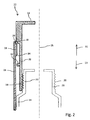
薬物送達デバイス10のキャップ・アセンブリ22およびハウジング部材12、14の第1の相互連結は、多少従来のクリップ留め設計を備えるが、図2および図3は、キャップ・アセンブリ22のための安全ロックを提供する第2の別個の相互連結を示す。図2による縦断面図に示すように、キャップ・アセンブリ22は、2つの部材、すなわちキャップ本体26およびインターロック部材24を備える。キャップ本体26は、カートリッジ・ホルダ14を受けるカップ状レセプタクルを備え、インターロック部材24は、キャップ本体26に軸方向に平行に延びる内部スリーブ36を備える。
The first interconnection of the
インターロック部材24は、さらに、キャップ本体26の遠位端に配置されて、そこから突出する。インターロック部材24は、キャップ本体26により回転可能に支持され、たとえば、キャップ本体26に対して縦軸15の周りを自由に回転することができる。インターロック部材24の内部スリーブ36は、カートリッジ・ホルダ14の遠位ソケット21の外側ねじ山20にねじ係合するように構成された内側ねじ山38を備える。加えて、インターロック部材24は、キャップ本体26に対して、所定の限界内で軸方向に摺動可能に移動することができる。これらの遠位および近位限界は、キャップ本体26の内壁およびインターロック部材24のスリーブ36の外壁に設けられた、互いに対応する相互係合停止面28、30、32、34により提供され管理される。
The
スリーブ36を、カートリッジ・ホルダ14のねじ付ソケット21にねじ留めすることにより、インターロック部材24の近位向きの停止面30がキャップ本体26の半径方向内側に突出または増厚する部分33の遠位向きの停止面28に当接するまで、インターロック部材24全体を近位方向13に移動させることができる。停止面30、28が互いに当接するとき、キャップ本体26が近位向きの保持力を受けるため、キャップ・アセンブリ22およびカートリッジ・ホルダ14の自動分解を妨げる。キャップ・アセンブリ22を解放し係合解除するために、インターロック部材24のねじをねじ付ソケット部分21から緩めて、互いに対応するねじ山20、38が係合解除されるまで、インターロック部材24およびその内部スリーブ36を遠位方向11に変位させる必要がある。
The
係合解除構成に到達するとすぐに、キャップ本体26が解放されてカートリッジ・ホルダ14から遠位方向11に引き離される。キャップ本体26およびインターロック部材24が、ある種の交互配置または入れ子構成に配置されるので、キャップ本体26およびインターロック部材24の軸方向11、13への相対変位が制限される。キャップ本体26の遠位部分33は、インターロック部材24またはその内部スリーブ36の遠位停止面30および近位停止面32の間に配置され、それらの間で案内される。したがって、キャップ本体26の近位向き停止面34がインターロック部材34の近位停止部材32の遠位向き当接面と互いに当接することにより、インターロック部材24とキャップ本体26との係合解除を防止する。その結果、キャップ・アセンブリ22は、カートリッジ・ホルダ14に組み付けられていないときでも、その部材24、26に分解されるおそれがない。
As soon as the disengagement configuration is reached, the
加えて、停止面32、34が互いに当接することにより、カートリッジ・ホルダ14またはハウジング12とのキャップ本体26の第1の相互連結の係合解除を支持することもできる。このように、インターロック部材24のねじをカートリッジ・ホルダ14の遠位ソケット21から緩めることにより、前記停止面32、34が互いに当接するときに、キャップ本体26のそれぞれの遠位向きの変位を生じさせるため、カートリッジ・ホルダ14とハウジング部材12とのインターフェース18に一般的にスナップ嵌めされる第1の相互連結部材23を解放する。
In addition, the stop surfaces 32, 34 can abut each other to support disengagement of the first interconnection of the
内部スリーブ36およびねじ付ソケット21のねじ係合の代わりに、互いに対応するスナップ嵌めまたはクリップ留め要素によってポジティブ・インターロックを提供することも考えられる。
As an alternative to the threaded engagement of the
図3による実施形態は、図2に関して記載し説明したキャップ本体26と略同一のキャップ本体26を有する異なるキャップ・アセンブリ42に関する。図3による実施形態において、インターロック部材40が図2による実施形態と実質的に異なるのは、その内部スリーブ44が、カートリッジ・ホルダ50のソケット部分21の近位部分に設けられた半径方向外側に延びる留め部材48に係合するように構成された、半径方向内側に延びる掛止部材46を備える点である。掛止部材46は、好ましくは、インターロック部材40の近位端に配置される。掛止部材46は、半径方向内側に周方向に断続するフランジ部分46に似ていてもよい。
The embodiment according to FIG. 3 relates to a
このようにして、インターロック部材40およびカートリッジ・ホルダ50のスナップ嵌めおよびポジティブ・ロックを達成することができる。半径方向外側に延びる留め部材48は、周方向に延びるが断続するリムを備えることができ、またはインターロック部材40の内部スリーブ44の近位端に配置された半径方向内側に延びる掛止部材46と嵌合するための、複数の半径方向外側に延びる突起を特色とすることができる。キャップ本体26およびインターロック部材40は、回転軸としての縦軸15に対して自由に回転可能であってもよい。
In this way, a snap fit and positive lock of the
インターロック部材の内部スリーブ44は、斜めの、または傾斜した停止面32、30をその近位および遠位限界に有する凹部35を備える。キャップ本体26の半径方向に増厚する部分33は、対応する形状であり、内部スリーブ44に形成された凹部35に一致する。このようにして、スリーブ44およびインターロック部材40はキャップ本体26に対して自由に回転することができるが、キャップ本体26およびインターロック部材40は軸方向に固定されたままとなる。したがって、キャップ・アセンブリ42がカートリッジ・ホルダ50に取り付けられると、インターロック部材が半径方向外側に延びる突起48に自動的に係合する。キャップ本体26とハウジング12、50との間、ならびにインターロック部材40とカートリッジ・ホルダ50との間の第1および第2の相互連結を、略同時に確立することができる。図3に示すように、突起またはリム48および掛止部材46が互いに係合することにより、インターロック部材40がカートリッジ・ホルダ50から自動解放されることを効果的に防止するため、キャップ本体26のための安全ロックとして機能する。
The
半径方向内側に延びる掛止部材46が、突起48または周方向に延びるリム48の対応する形状の断続と軸方向11、13に同一平面になるまで、インターロック部材40をカートリッジ・ホルダ50に対して回転させることによって、インターロック部材40の係合解除を達成することができる。その後、インターロック部材40およびキャップ本体26を、カートリッジ・ホルダ50に対して遠位方向に変位させることができる。
The interlocking
図3による実施形態は2つの別個の部材、すなわちキャップ本体26およびインターロック部材40を示すが、このようなキャップ・アセンブリ42は、キャップ本体26およびインターロック部材40が一体形成される単一部材として設計されていてもよい。その場合、インターロック部材40の回転係合解除運動も、キャップ本体26の対応する回転運動に伴って生じる。
Although the embodiment according to FIG. 3 shows two separate members, a
10 薬物送達デバイス
11 遠位方向
12 ハウジング
13 近位方向
14 カートリッジ・ホルダ
15 用量ボタン
16 点検窓
18 インターフェース
20 外側ねじ山
21 ソケット部分
22 キャップ・アセンブリ
23 相互連結部材
24 インターロック部材
26 キャップ本体
28 停止面
30 停止面
32 停止面
33 増厚部分
34 停止面
35 凹部
36 内部スリーブ
38 内側ねじ山
40 インターロック部材
42 キャップ・アセンブリ
44 内部スリーブ
46 掛止部材
48 留め部材
50 カートリッジ・ホルダ
DESCRIPTION OF
Claims (10)
該キャップ本体(26)に動作可能に係合され、デバイスの投薬端(14;50)の遠位端部(21)に解放可能に係合して、キャップ本体(26)のための安全ロックを提供する第2の相互連結部材(38;46)を備えたインターロック部材(24;40)とを備え、
該インターロック部材(24;40)が、キャップ本体(26)の遠位端から近位方向へ、軸方向内側に延びる内部スリーブ(36;44)を備え、第2の相互連結部材(38;46)が内部スリーブ(36;44)の近位部分に配置される、薬物送達デバイスのためのキャップ・アセンブリであって、
第2の相互連結部材(38;46)が、遠位端部(21)にねじ係合可能であるか、またはポジティブ・インターロック可能であり、
ここで、キャップ本体(26)およびインターロック部材(24;40)が、互いに対応して半径方向に延びる停止要素(28、30、32、34)を備えて、キャップ本体(26)とインターロック部材(24;40)との相対軸方向変位を制限し、インターロック部材が、停止要素(28、30、32、34)を介して、キャップ本体(26)に近位向きの保持力を及ぼせるようにすることを特徴とする上記キャップ・アセンブリ。 A drug comprising a cup-shaped receptacle having at least a first interconnecting member (23) at the proximal end to provide a first interconnect with the housing member (12, 14; 50) of the drug delivery device (10) projecting drug end of the delivery device; and (14 50) the cap body for receiving and protecting (26),
A safety lock for the cap body (26) operably engaged with the cap body (26) and releasably engaged with the distal end (21) of the dispensing end (14; 50) of the device. An interlock member (24; 40) with a second interconnecting member (38; 46) providing
The interlock member (24; 40) comprises an inner sleeve (36; 44) extending axially inwardly from the distal end of the cap body (26) to a second interconnecting member (38; 46) a cap assembly for a drug delivery device, disposed in the proximal portion of the inner sleeve (36; 44),
The second interconnecting member (38; 46) is threadably engageable with the distal end (21) or is positively interlockable;
Here, the cap body (26) and the interlock member (24; 40) are provided with stop elements (28, 30, 32, 34) extending in a radial direction corresponding to each other, so that the cap body (26) and the interlock are provided. Limiting relative axial displacement with the member (24; 40), the interlock member exerts a proximal holding force on the cap body (26) via the stop element (28, 30, 32, 34). The cap assembly described above, wherein
求項1〜3のいずれか一項に記載のキャップ・アセンブリ。 Interlocking element (24; 40) of Ru is formed at the distal end of the cap body (26), the cap assembly according to any one of claims 1 to 3.
カートリッジの近位に位置するピストンに動作可能に係合するための駆動機構を収容するように構成された、カートリッジ・ホルダ(14;50)に連結可能な近位ハウジング部材(12)と、
請求項1〜6のいずれか一項に記載のキャップ・アセンブリ(22;42)と
を備えた、薬剤の所定の用量を注射するための薬物送達デバイス。 A dispensing end with a cartridge holder (14; 50) for receiving a cartridge filled with medicament to be dispensed;
A proximal housing member (12) connectable to a cartridge holder (14; 50) configured to receive a drive mechanism for operably engaging a piston located proximal to the cartridge;
A drug delivery device for injecting a predetermined dose of medicament comprising a cap assembly (22; 42) according to any one of the preceding claims.
薬物送達デバイスのカートリッジ・ホルダ(14;50)を、取付位置に到達するまで、キャップ本体(26)のカップ状レセプタクルに挿入する工程と、
キャップ本体(26)に動作可能に係合されたインターロック部材(24;40)を起動し、カートリッジ・ホルダ(14;50)の遠位端部(21)に解放可能に係合して、キャップ本体(26)のための安全ロックを提供する工程を含む上記方法。 A method of releasably interconnecting a cap assembly according to any one of claims 1-6 to a cartridge holder of a drug delivery device comprising:
Cartridge Hol da for drug delivery; (14 50), until it reaches the mounting position, the step of inserting the cup-shaped receptacle of the cap body (26),
Activating the interlock member (24; 40) operably engaged with the cap body (26) and releasably engaging the distal end (21) of the cartridge holder (14; 50); Providing a safety lock for the cap body (26).
Applications Claiming Priority (3)
| Application Number | Priority Date | Filing Date | Title |
|---|---|---|---|
| EP11181944.7 | 2011-09-20 | ||
| EP11181944 | 2011-09-20 | ||
| PCT/EP2012/068293 WO2013041504A1 (en) | 2011-09-20 | 2012-09-18 | Cap assembly for a drug delivery device |
Publications (2)
| Publication Number | Publication Date |
|---|---|
| JP2014526329A JP2014526329A (en) | 2014-10-06 |
| JP6139532B2 true JP6139532B2 (en) | 2017-05-31 |
Family
ID=44712897
Family Applications (1)
| Application Number | Title | Priority Date | Filing Date |
|---|---|---|---|
| JP2014530264A Expired - Fee Related JP6139532B2 (en) | 2011-09-20 | 2012-09-18 | Cap assembly for drug delivery device |
Country Status (6)
| Country | Link |
|---|---|
| US (1) | US9844632B2 (en) |
| EP (1) | EP2758103B1 (en) |
| JP (1) | JP6139532B2 (en) |
| CA (1) | CA2845400A1 (en) |
| DK (1) | DK2758103T3 (en) |
| WO (1) | WO2013041504A1 (en) |
Families Citing this family (15)
| Publication number | Priority date | Publication date | Assignee | Title |
|---|---|---|---|---|
| WO2015037545A1 (en) * | 2013-09-13 | 2015-03-19 | テルモ株式会社 | Liquid-administering instrument |
| WO2017089269A1 (en) * | 2015-11-27 | 2017-06-01 | Sanofi-Aventis Deutschland Gmbh | Medicament injection device |
| USD819198S1 (en) | 2016-04-28 | 2018-05-29 | Amgen Inc. | Autoinjector with removable cap |
| TWI729141B (en) * | 2016-05-31 | 2021-06-01 | 德商賽諾菲阿凡提斯德意志有限公司 | Cap assembly for a drug delivery device and method for assembling a cap assembly |
| EP3492124A1 (en) | 2017-12-01 | 2019-06-05 | Sanofi | Injector device |
| USD1010811S1 (en) | 2019-09-30 | 2024-01-09 | Amgen Inc. | Handheld drug delivery device |
| USD1030041S1 (en) | 2020-01-14 | 2024-06-04 | Amgen Inc. | Handheld drug delivery device |
| USD1030040S1 (en) | 2020-01-14 | 2024-06-04 | Amgen Inc. | Handheld drug delivery device |
| USD962423S1 (en) | 2020-11-05 | 2022-08-30 | Amgen Inc. | Handheld drug delivery device |
| USD973866S1 (en) | 2020-11-05 | 2022-12-27 | Amgen Inc. | Handheld drug delivery device |
| USD974547S1 (en) | 2020-11-05 | 2023-01-03 | Amgen Inc. | Handheld drug delivery device |
| USD985117S1 (en) | 2021-03-10 | 2023-05-02 | Amgen Inc. | Handheld drug delivery device |
| USD985116S1 (en) | 2021-03-10 | 2023-05-02 | Amgen Inc. | Handheld drug delivery device |
| USD985118S1 (en) | 2021-03-10 | 2023-05-02 | Amgen Inc. | Handheld drug delivery device |
| USD985119S1 (en) | 2021-03-30 | 2023-05-02 | Amgen Inc. | Handheld drug delivery device |
Family Cites Families (19)
| Publication number | Priority date | Publication date | Assignee | Title |
|---|---|---|---|---|
| US5624402A (en) * | 1994-12-12 | 1997-04-29 | Becton, Dickinson And Company | Syringe tip cap |
| JP3647958B2 (en) * | 1995-06-16 | 2005-05-18 | 株式会社アルテ | Container / Syringe |
| WO2002074369A1 (en) | 2001-03-20 | 2002-09-26 | Disetronic Licensing Ag | Needle protective covering |
| US6585691B1 (en) * | 2001-05-11 | 2003-07-01 | Jonathan J. Vitello | Tamper evident end cap assembly for a loaded syringe and process |
| US20110098656A1 (en) * | 2005-09-27 | 2011-04-28 | Burnell Rosie L | Auto-injection device with needle protecting cap having outer and inner sleeves |
| GB2438593B (en) * | 2006-06-01 | 2011-03-30 | Cilag Gmbh Int | Injection device (cap removal feature) |
| CN103316402A (en) * | 2006-06-30 | 2013-09-25 | 艾伯维生物技术有限公司 | Automatic injection device |
| US7632244B2 (en) * | 2006-08-10 | 2009-12-15 | Comar, Inc. | Tamper evident tip cap assembly |
| GB0621310D0 (en) * | 2006-10-27 | 2006-12-06 | Liversidge Barry P | Medical needle safety devices |
| ATE495777T1 (en) * | 2006-12-22 | 2011-02-15 | Novo Nordisk As | SHIELDABLE NEEDLE ARRANGEMENT WITH PRE-TENSIONED SAFETY SHIELD |
| US7871397B2 (en) * | 2006-12-26 | 2011-01-18 | Stat Medical Devices, Inc. | Pen needle tip |
| CN101868270B (en) | 2007-09-25 | 2013-10-16 | 贝克顿迪金森法国公司 | Autoinjector with deguard including wiping trace display device |
| GB0724907D0 (en) | 2007-12-20 | 2008-01-30 | Ucb Pharma Sa | Auto-injector |
| WO2009137486A1 (en) * | 2008-05-05 | 2009-11-12 | Becton, Dickinson And Company | Drug delivery device having cartridge with enlarged distal end |
| US9089650B2 (en) | 2008-10-01 | 2015-07-28 | Novo Nordisk A/S | Medical assembly with monitoring device |
| EP2201967A1 (en) * | 2008-12-23 | 2010-06-30 | Sanofi-Aventis Deutschland GmbH | Drug delivery device |
| US20110023281A1 (en) * | 2009-04-30 | 2011-02-03 | Stat Medical Devices, Inc. | Pen injection device cap with integral pen needle quick release and/or removal system |
| US9700681B2 (en) | 2009-05-15 | 2017-07-11 | Stat Medical Devices, Inc. | Pen needle with quick release and/or removal system |
| WO2010142813A1 (en) * | 2009-06-12 | 2010-12-16 | Novo Nordisk A/S | Drug delivery device with cap functions for needle assembly |
-
2012
- 2012-09-18 US US14/240,802 patent/US9844632B2/en not_active Expired - Fee Related
- 2012-09-18 CA CA2845400A patent/CA2845400A1/en not_active Abandoned
- 2012-09-18 DK DK12761608.4T patent/DK2758103T3/en active
- 2012-09-18 WO PCT/EP2012/068293 patent/WO2013041504A1/en not_active Ceased
- 2012-09-18 JP JP2014530264A patent/JP6139532B2/en not_active Expired - Fee Related
- 2012-09-18 EP EP12761608.4A patent/EP2758103B1/en not_active Not-in-force
Also Published As
| Publication number | Publication date |
|---|---|
| US20140323976A1 (en) | 2014-10-30 |
| EP2758103A1 (en) | 2014-07-30 |
| DK2758103T3 (en) | 2016-09-26 |
| US9844632B2 (en) | 2017-12-19 |
| JP2014526329A (en) | 2014-10-06 |
| EP2758103B1 (en) | 2016-06-29 |
| CA2845400A1 (en) | 2013-03-28 |
| WO2013041504A1 (en) | 2013-03-28 |
Similar Documents
| Publication | Publication Date | Title |
|---|---|---|
| JP6139532B2 (en) | Cap assembly for drug delivery device | |
| JP6261519B2 (en) | Fixed dose drug delivery device | |
| JP6616315B2 (en) | Sheath removal mechanism | |
| JP6412121B2 (en) | Autoinjector | |
| JP6339558B2 (en) | Pen syringe | |
| JP6577942B2 (en) | Injection device | |
| JP6073462B2 (en) | Cartridge holder and pen-type syringe | |
| JP6412215B2 (en) | Actuating mechanism for drug delivery device and drug delivery device | |
| JP6487428B2 (en) | Autoinjector | |
| JP6377643B2 (en) | Drug delivery device with needle protection | |
| JP6326054B2 (en) | Drug delivery device with usage status indicator | |
| JP6433484B2 (en) | Drive mechanism of drug delivery device | |
| JP2015508690A (en) | Drawer device for withdrawing drug from container only once | |
| JP6419158B2 (en) | Drive mechanism of drug delivery device | |
| JP6584582B2 (en) | Piston rod body support for drug delivery device, piston rod arrangement, and piston rod body | |
| JP6386481B2 (en) | Assembly for a drug delivery device | |
| JP6257602B2 (en) | Piston rod for drug delivery device and drug delivery device comprising piston rod | |
| JP2014516704A (en) | Use of switches to facilitate safe and convenient installation and removal procedures | |
| JP6496316B2 (en) | Drug delivery device housing | |
| JP2016530937A (en) | Assembly for a drug delivery device and method for assembling a drug delivery device | |
| JP2015511514A (en) | Drug delivery device housing | |
| JP6298056B2 (en) | Cap for drug delivery device and drug delivery device | |
| JP7423596B2 (en) | Drug delivery device and method of assembling the same | |
| JP2018513753A (en) | Drug delivery device |
Legal Events
| Date | Code | Title | Description |
|---|---|---|---|
| A529 | Written submission of copy of amendment under article 34 pct |
Free format text: JAPANESE INTERMEDIATE CODE: A529 Effective date: 20140423 |
|
| A621 | Written request for application examination |
Free format text: JAPANESE INTERMEDIATE CODE: A621 Effective date: 20150908 |
|
| A977 | Report on retrieval |
Free format text: JAPANESE INTERMEDIATE CODE: A971007 Effective date: 20160610 |
|
| A131 | Notification of reasons for refusal |
Free format text: JAPANESE INTERMEDIATE CODE: A131 Effective date: 20160628 |
|
| A521 | Request for written amendment filed |
Free format text: JAPANESE INTERMEDIATE CODE: A523 Effective date: 20160831 |
|
| A131 | Notification of reasons for refusal |
Free format text: JAPANESE INTERMEDIATE CODE: A131 Effective date: 20170104 |
|
| A521 | Request for written amendment filed |
Free format text: JAPANESE INTERMEDIATE CODE: A523 Effective date: 20170329 |
|
| TRDD | Decision of grant or rejection written | ||
| A01 | Written decision to grant a patent or to grant a registration (utility model) |
Free format text: JAPANESE INTERMEDIATE CODE: A01 Effective date: 20170411 |
|
| A61 | First payment of annual fees (during grant procedure) |
Free format text: JAPANESE INTERMEDIATE CODE: A61 Effective date: 20170427 |
|
| R150 | Certificate of patent or registration of utility model |
Ref document number: 6139532 Country of ref document: JP Free format text: JAPANESE INTERMEDIATE CODE: R150 |
|
| R250 | Receipt of annual fees |
Free format text: JAPANESE INTERMEDIATE CODE: R250 |
|
| LAPS | Cancellation because of no payment of annual fees |