JP6139088B2 - Vehicle detection device - Google Patents
Vehicle detection device Download PDFInfo
- Publication number
- JP6139088B2 JP6139088B2 JP2012220429A JP2012220429A JP6139088B2 JP 6139088 B2 JP6139088 B2 JP 6139088B2 JP 2012220429 A JP2012220429 A JP 2012220429A JP 2012220429 A JP2012220429 A JP 2012220429A JP 6139088 B2 JP6139088 B2 JP 6139088B2
- Authority
- JP
- Japan
- Prior art keywords
- vehicle
- distance
- pixel
- detection device
- vehicle detection
- Prior art date
- Legal status (The legal status is an assumption and is not a legal conclusion. Google has not performed a legal analysis and makes no representation as to the accuracy of the status listed.)
- Expired - Fee Related
Links
Images


Classifications
-
- H—ELECTRICITY
- H04—ELECTRIC COMMUNICATION TECHNIQUE
- H04N—PICTORIAL COMMUNICATION, e.g. TELEVISION
- H04N7/00—Television systems
- H04N7/18—Closed-circuit television [CCTV] systems, i.e. systems in which the video signal is not broadcast
-
- G—PHYSICS
- G06—COMPUTING; CALCULATING OR COUNTING
- G06T—IMAGE DATA PROCESSING OR GENERATION, IN GENERAL
- G06T7/00—Image analysis
- G06T7/20—Analysis of motion
- G06T7/254—Analysis of motion involving subtraction of images
-
- G—PHYSICS
- G08—SIGNALLING
- G08G—TRAFFIC CONTROL SYSTEMS
- G08G1/00—Traffic control systems for road vehicles
- G08G1/01—Detecting movement of traffic to be counted or controlled
- G08G1/04—Detecting movement of traffic to be counted or controlled using optical or ultrasonic detectors
-
- G—PHYSICS
- G06—COMPUTING; CALCULATING OR COUNTING
- G06T—IMAGE DATA PROCESSING OR GENERATION, IN GENERAL
- G06T2207/00—Indexing scheme for image analysis or image enhancement
- G06T2207/10—Image acquisition modality
- G06T2207/10016—Video; Image sequence
- G06T2207/10021—Stereoscopic video; Stereoscopic image sequence
-
- G—PHYSICS
- G06—COMPUTING; CALCULATING OR COUNTING
- G06T—IMAGE DATA PROCESSING OR GENERATION, IN GENERAL
- G06T2207/00—Indexing scheme for image analysis or image enhancement
- G06T2207/10—Image acquisition modality
- G06T2207/10028—Range image; Depth image; 3D point clouds
-
- G—PHYSICS
- G06—COMPUTING; CALCULATING OR COUNTING
- G06T—IMAGE DATA PROCESSING OR GENERATION, IN GENERAL
- G06T2207/00—Indexing scheme for image analysis or image enhancement
- G06T2207/30—Subject of image; Context of image processing
- G06T2207/30236—Traffic on road, railway or crossing
Description
本発明の実施形態は、道路上の特定領域を入出する車両を検知する車両検知装置に関する。 Embodiments described herein relate generally to a vehicle detection device that detects a vehicle entering and exiting a specific area on a road.
料金収受システムに用いられる車両検知装置では、一般に、赤外線を用いた透過型のポールセンサによって車両の通過を検知する。すなわち、一対のポールセンサは、走行車線の両側に設置され、互いに赤外線ビームを照射して検知し合い、車両が赤外線ビームを横切った瞬間を検知するので、比較的安定して車両の通過を検知することができる。しかしながら、ポールセンサは、設置時に掘削工事が必要であり、設置位置を調整するための測定器並びに作業も別途必要であることから、工事・調整コストがかかる。 In a vehicle detection device used in a toll collection system, generally, the passage of a vehicle is detected by a transmission-type pole sensor using infrared rays. In other words, a pair of pole sensors are installed on both sides of the driving lane, detect each other by irradiating each other with an infrared beam, and detect the moment when the vehicle crosses the infrared beam. can do. However, since the pole sensor requires excavation work at the time of installation, and a measuring instrument and work for adjusting the installation position are also required separately, construction and adjustment costs are required.
以上のように、車両検知装置に対して、工事・調整コストを極力抑えたい要求がある。 As described above, there is a demand for the vehicle detection device to suppress construction / adjustment costs as much as possible.
代替案として、近年比較的安価に入手可能となっているカメラが注目されている。カメラを用いて車両の存在を検知する方法は、交通状況把握装置等で実用化されている。この交通状況把握装置では、動画処理による車両検知を行っている。 As an alternative, a camera that has become available at a relatively low cost in recent years has attracted attention. A method of detecting the presence of a vehicle using a camera has been put into practical use in a traffic condition grasping device or the like. In this traffic condition grasping device, vehicle detection is performed by moving image processing.
しかしながら、カメラを用いる方法は、光学条件の変化の影響を大きく受けるので、高精度な検出機能のロバスト性の確保が困難である。このため、光学条件の影響を低減する施策を行ったステレオ方式を採用した上で、従来の透過型ポールセンサと同等な精度を確保する技術開発が必要となる。また、設置の容易性、機器コストの低減要求から、特にカメラ間距離が短い場合においては、光学条件の変動に左右されずにカメラから離れた位置での視差を安定して確保することが困難となる。 However, since a method using a camera is greatly affected by changes in optical conditions, it is difficult to ensure robustness of a highly accurate detection function. For this reason, it is necessary to develop a technology that ensures the same accuracy as that of a conventional transmission pole sensor after adopting a stereo method in which measures for reducing the influence of optical conditions are adopted. Also, due to the ease of installation and equipment cost reduction requirements, especially when the distance between cameras is short, it is difficult to stably secure parallax at a position away from the camera without being affected by fluctuations in optical conditions. It becomes.
そこで、目的は、ステレオカメラの採用において、光学条件の変化に影響されず、撮影画像から車両の入出を高精度に検知することのできる車両検知装置を提供することにある。 Accordingly, an object of the present invention is to provide a vehicle detection device that can accurately detect the entry / exit of a vehicle from a photographed image without being affected by changes in optical conditions when a stereo camera is employed.
本実施形態によれば、車両検知装置は、ステレオカメラで撮像された各々の撮像画像に基づいて前記ステレオカメラの視野内を入出する車両を検知する車両検知装置であって、エッジ強調手段と、視差データ計測手段と、視差データ棄却手段と、距離データ計測手段と、距離画像作成手段と、状態判定手段と、入出検知手段とを具備する。エッジ強調手段は、前記各々の撮像画像について、車両の上下方向に延びる線上に存在するエッジに対し、エッジ強調を行う。視差データ計測手段は、前記エッジ強調された各々の撮像画像から視差データを画素毎に計測する。視差データ棄却手段は、前記各々の撮像画像内の画素の輝度の分散を求め、その結果より前記画素毎の視差データを選択的に棄却する。距離データ計測手段は、前記視差データから前記ステレオカメラと撮像対象との間の距離を示す距離データを画素毎に計測する。距離画像作成手段は、前記距離を画素毎に有する距離画像を作成する。状態判定手段は、前記車両の進行方向に前記距離画像を複数の領域に分割して複数の基準区間を形成し、複数の基準区間それぞれで、予め車両のない状態で計測される背景距離データと前記距離データ計測手段で車両の入出時に指定時刻毎に計測される距離データとの差分を求め、前記基準区間毎に差分の変化量を時刻毎に求め、前記基準区間毎に差分の変化量を閾値と比較することで、物体の有無に対応する状態を時刻毎に判定する。入出検知手段は、前記時刻毎の状態判定を保持し、前記車両の遷移を判定し、前記車両の入出を検知する。 According to this embodiment, the vehicle detection device, a vehicle detection device which detects the vehicle into and out of the inside of the field of view of the stereo camera based on each of images captured by the stereo camera, and edge enhancement means, Disparity data measurement means, disparity data rejection means, distance data measurement means, distance image creation means, state determination means, and entry / exit detection means are provided. The edge emphasizing unit performs edge emphasis on each of the captured images with respect to an edge existing on a line extending in the vertical direction of the vehicle. The parallax data measuring means measures parallax data for each pixel from each of the captured images with the edge enhanced. The parallax data rejection means obtains the variance of the luminance of the pixels in each captured image, and selectively rejects the parallax data for each pixel from the result. The distance data measuring unit measures distance data indicating a distance between the stereo camera and the imaging target for each pixel from the parallax data. The distance image creating means creates a distance image having the distance for each pixel. The state determination unit divides the distance image into a plurality of regions in the traveling direction of the vehicle to form a plurality of reference sections, and each of the plurality of reference sections includes background distance data measured in advance without a vehicle, said distance data measurement means obtains a difference between the distance data measured for each specified time when entering and leaving the vehicle, the determined every time the variation of the difference between every said reference zone, the variation of the difference for each of said reference sections Is compared with a threshold value to determine a state corresponding to the presence or absence of an object for each time. The entry / exit detection means holds state determination for each time, determines transition of the vehicle, and detects entry / exit of the vehicle.
以下、実施形態について、図面を参照して説明する。なお、以降の図における同一部分には同一符号を付して、その詳しい説明を省略し、異なる部分について主に述べる。 Hereinafter, embodiments will be described with reference to the drawings. In addition, the same code | symbol is attached | subjected to the same part in subsequent figures, the detailed description is abbreviate | omitted, and a different part is mainly described.
図1は、本実施形態に係る車両検知装置を適用した車両情報処理システムの構成を示す模式図である。この車両情報処理システムは、レーザセンサ10、ステレオカメラ20、ETC(Electronic Toll Collection)システム30及び車両検知装置100を備えている。
FIG. 1 is a schematic diagram illustrating a configuration of a vehicle information processing system to which a vehicle detection device according to the present embodiment is applied. The vehicle information processing system includes a
レーザセンサ10は、ステレオカメラ20に近接して配置され、撮影画像の背景となる走行車線までの距離を得るセンサであり、得られた背景距離データは車両検知装置100に送られる。ここで、上記レーザセンサ10は、ステレオカメラ20に近接した位置から走行車線に向けて垂直に且つ車線を横切る方向に沿ってレーザビームをスキャンし、レーザビームが反射する地点までの距離を計測した背景距離データを得るセンサである。
The
ステレオカメラ20は、複数のカメラを所定の視差が得られるように配置した撮像装置である。本実施形態では、複数のカメラを上下に並べて配置し、各カメラにより車両が進行する車線を撮像し、各々の撮像画像を車両検知装置100に送出する。ここでは、例として2台のカメラを用いて、一方のカメラで撮像した画像を基準画像とし、他方のカメラで撮像された画像を参照画像とする。 The stereo camera 20 is an imaging device in which a plurality of cameras are arranged so as to obtain a predetermined parallax. In the present embodiment, a plurality of cameras are arranged side by side, the lane in which the vehicle travels is captured by each camera, and each captured image is sent to the vehicle detection device 100. Here, as an example, using two cameras, an image captured by one camera is used as a standard image, and an image captured by the other camera is used as a reference image.
ステレオカメラ20内の各カメラは、予め設定したフレームレートで動画像を撮像するディジタルカメラである。このステレオカメラ20は、料金所のアイランド部分に立つポールに設置され、車両の進行方向に対し、上下に並ぶそれぞれのカメラが上斜め方向から撮像し、車両が横方向に通過するように視野(撮像領域)が設定されている。すなわち、ステレオカメラ20は、斜め上方から路面を撮像可能な位置に設置される。また、ステレオカメラ20は、カメラ視野内を走行する車両について、タイヤ(車軸)と地面との接地部分が映るよう調整される。また、ステレオカメラ20は、牽引棒などの牽引構造物を撮像する際に、車両による死角が発生しないように、車両の進行方向に対して垂直な方向から撮像可能な位置に設置される。なお、料金所では、車線内の車両の位置を適切に把握するため、1車線あたり3〜4箇所にステレオカメラ20及び車両検知装置100を設置してもよい。 Each camera in the stereo camera 20 is a digital camera that captures a moving image at a preset frame rate. This stereo camera 20 is installed on a pole standing on the island portion of the toll booth, and each camera arranged in the vertical direction with respect to the traveling direction of the vehicle captures an image from an oblique direction so that the vehicle passes laterally ( (Imaging area) is set. That is, the stereo camera 20 is installed at a position where the road surface can be imaged from obliquely above. In addition, the stereo camera 20 is adjusted so that a grounded portion between a tire (axle) and the ground is reflected in a vehicle traveling in the camera field of view. In addition, the stereo camera 20 is installed at a position where imaging can be performed from a direction perpendicular to the traveling direction of the vehicle so that a blind spot due to the vehicle does not occur when imaging a towing structure such as a tow bar. In the toll gate, the stereo camera 20 and the vehicle detection device 100 may be installed at 3 to 4 locations per lane in order to appropriately grasp the position of the vehicle in the lane.
尚、ステレオカメラ20としては、上下のカメラに代えて、1枚のレンズで光学的に車両の上下の撮像画像を得る撮像装置としてもよい。例えば、ステレオカメラ20は、特殊なレンズにより、1台のカメラで同時に双方向からの映像を一度に分岐できる場合には、単数のカメラでハードウェアを構築してもよい。例えば、光の入り口には2つのレンズを備え、内部には光路を曲げるプリズムが配置されたウェッジプリズム偏光方式を用いたレンズ等が、適宜使用可能である。 Note that the stereo camera 20 may be an imaging device that optically obtains upper and lower captured images of the vehicle with a single lens, instead of the upper and lower cameras. For example, the stereo camera 20 may be configured with a single camera if a single lens can branch images from both directions at the same time using a special lens. For example, a lens using a wedge prism polarization system in which two lenses are provided at the light entrance and a prism that bends the optical path is disposed inside can be used as appropriate.
ステレオカメラ20によって得られた撮像画像は、撮像時刻を示すタイムコードを含んでいる。ステレオカメラ20、ETCシステム30及び車両検知装置100は、互いに同期した時刻情報を生成する時計装置(図示せず)を有する。なお、撮像画像は、他の手法によって、ステレオカメラ20、ETCシステム30及び車両検知装置100が同期して動作すれば、すなわち、ステレオカメラ20の画像データの撮像時刻をETCシステム30及び車両検知装置100が認識できれば、必ずしもタイムコードを含まなくてもよい。 The captured image obtained by the stereo camera 20 includes a time code indicating the imaging time. The stereo camera 20, the ETC system 30, and the vehicle detection device 100 have a clock device (not shown) that generates time information synchronized with each other. If the stereo camera 20, the ETC system 30, and the vehicle detection device 100 operate in synchronism with other methods, that is, the captured time of the image data of the stereo camera 20 is determined by the ETC system 30 and the vehicle detection device. If 100 can be recognized, the time code may not necessarily be included.
このとき、ステレオカメラ20では、大型車両のような高さ(4.0m以内)においても、車両の下端(タイヤ接地部分)から上端(屋根)までが映っているものとする。また、ステレオカメラ20では、映像が動画で撮像され、車両の通行に際しては、時速80km/hまでの移動を想定して、ステレオカメラ20の視野内への通行履歴として、車両1台につき、少なくとも数フレーム(進入および退出)が映っているものとする。 At this time, in the stereo camera 20, even from a height (within 4.0 m) of a large vehicle, it is assumed that the lower end (tire contact portion) to the upper end (roof) of the vehicle are reflected. Further, in the stereo camera 20, the video is captured as a moving image, and when traveling through the vehicle, assuming that the vehicle travels up to 80 km / h, the travel history into the field of view of the stereo camera 20 is at least per vehicle. It is assumed that several frames (entrance and exit) are shown.
ETCシステム30は、高速道路等の有料道路を通行する車両に対して課せられる通行料金を自動的に徴収する料金収受装置であり、車両に搭載されるETC車載器と無線通信し、通過車両を特定する情報を取得する。このETC車載器は、一般に、少なくとも無線通信を行うためのアンテナがフロントガラスを介して視認できる位置に設置される。 The ETC system 30 is a toll collection device that automatically collects tolls imposed on vehicles traveling on toll roads such as expressways, and wirelessly communicates with ETC on-board equipment mounted on the vehicles, Get information to identify. This ETC on-board device is generally installed at a position where at least an antenna for performing wireless communication can be visually recognized through a windshield.
図2は、本実施形態に係る車両検知装置100の構成を示すブロック図である。 FIG. 2 is a block diagram illustrating a configuration of the vehicle detection device 100 according to the present embodiment.
図2に示すように、車両検知装置100は、表示部110、ユーザインタフェース120、記憶部130、ネットワークインタフェース140及び制御部150を備えている。
As illustrated in FIG. 2, the vehicle detection device 100 includes a
表示部110は、LCD(Liquid Crystal Display)等を用いたディスプレイ装置であり、当該車両検知装置100の運用状況を始めとする種々の情報を表示する。
The
ユーザインタフェース120は、キーボード、マウス、タッチパネル等のユーザから指示を受け付けるインタフェースである。
The
記憶部130は、制御部150の制御プログラムや制御データを記憶する記憶装置であり、HDD、RAM、ROM及びフラッシュメモリ等の記憶手段を1つまたは複数用いたものである。制御データとしては、例えば、立体の形状を表す複数の部品データ(例、牽引棒の形状パターン、車軸の円形部分の形状データ、人物の一部の形状データ)等がある。すなわち、記憶部130は、複数の部品データを予め記憶する。牽引棒の形状パターンは、例えば、車両の進行方向に沿って長辺を有する長方形を示す形状パターンの如き、牽引棒の典型的な形状パターンを示す情報である。牽引棒の形状パターンは、近接した2台の車両と、被牽引車を牽引棒で牽引する1台の車両と、を区別する場合に記憶される。そのため、牽引棒の形状パターンは、両者を区別しない場合には省略可能となっている。
The
ネットワークインタフェース140は、LAN等のネットワークを通じて、ステレオカメラ20及びETCシステム30と通信するインタフェースである。
The
制御部150は、メモリを有するマイクロプロセッサを備え、記憶部130が記憶する制御プログラムや制御データにしたがって動作し、当該車両検知装置100の各部を統括して制御する。
The
この制御部150は、ステレオカメラ20により得られた各々の撮像画像から視差を求め、ステレオカメラ20の視野内(撮像領域内)の物体との距離データを計算する。また、制御部150は、レーザセンサ10により取得される背景距離データと計算された距離データとの差分により、視野内の物体の存在を確認し、その位置関係を時刻毎に記録し、物体の移動方向を判定して、車両の入出を検知する。なお、制御部150は、入出車両の検知に加え、実空間上における通過時刻(ETCシステム30の通信エリアの通過時刻)を予測する機能を有していてもよい。
The
また、制御部150は、例えば、以下の機能(f1)〜(f6)を備えている。
The
(f1) 各々の撮像画像について、車両の上下方向へのエッジ強調を行うエッジ強調機能。 (F1) An edge enhancement function that performs edge enhancement in the vertical direction of the vehicle for each captured image.
(f2) エッジ強調された各々の撮像画像間の視差データを画素毎に計測する視差データ計測機能。 (F2) A parallax data measurement function for measuring the parallax data between the captured images with edge enhancement for each pixel.
(f3) 推定視差と基準画像内および参照画像内の注目画素を含む小領域内の画素値の分散を求め、その結果により不要な視差データを棄却する視差データ棄却機能。 (F3) A parallax data rejection function that obtains the estimated parallax and dispersion of pixel values in a small area including the target pixel in the standard image and the reference image, and rejects unnecessary parallax data based on the result.
(f4) 上記視差データからステレオカメラと撮像対象との間の距離を示す距離データを画素毎に求め、この距離データを画素毎に有する距離画像を作成する距離データ計測・距離画像作成機能。 (F4) A distance data measurement / distance image creation function for obtaining distance data indicating the distance between the stereo camera and the imaging target for each pixel from the parallax data and creating a distance image having this distance data for each pixel.
(f5) 車両の進行方向に距離画像を分割して複数の基準区間を形成し、複数の基準区間それぞれで、予め車両のない状態で計測される背景距離データと距離データ計測機能で指定車両の入出時に時刻毎に計測される距離データとの差分を求め、基準区間毎に差分の変化量を時刻毎に求め、基準区間毎に差分の変化量を閾値と比較することで、車両の有無を時刻毎に状態判定する状態判定機能。 (F5) The distance image is divided in the traveling direction of the vehicle to form a plurality of reference sections, and each of the plurality of reference sections is measured in advance with the background distance data and the distance data measuring function measured in the absence of the vehicle. By calculating the difference from the distance data measured at each time when entering and leaving, obtaining the change amount of the difference for each reference section for each time, and comparing the change amount of the difference for each reference section with a threshold value, A state determination function that determines the state at each time.
(f6) 時刻毎の状態判定を保持し、その履歴が先頭、側面、及び後端の流れ、あるいは後端、側面、先頭の流れを監視することで車両の遷移方向を判定し、判定結果から車両の入出を検知する車両検知機能。 (F6) The state determination for each time is held, and the history of the vehicle determines the transition direction of the vehicle by monitoring the flow of the front, side, and rear end, or the flow of the rear end, side, and front, and from the determination result A vehicle detection function that detects vehicle entry and exit.
次に、上記のように構成された車両情報処理システムの動作について説明する。 Next, the operation of the vehicle information processing system configured as described above will be described.
図3は、本実施形態に係る車両検知装置100の処理の流れを示すフローチャートである。 FIG. 3 is a flowchart showing a process flow of the vehicle detection device 100 according to the present embodiment.
まず、車両検知装置100は、撮像画像入力にて、ステレオカメラ20で撮像された撮像画像(一方が基準画像、他方が参照画像)を入力する(ステップST1)。車両検知装置100は、平行等位化処理にて、入力された撮像画像の平行等位化及び歪み補正を行い(ステップST2)、輝度補正処理にて、平行等位化された撮像画像の輝度補正(ステップST3)を行う。車両検知装置100は、画像特徴抽出処理にて、各々の撮像画像について、ステップST3で補正された撮像画像を制御部150の機能(f1)により車両の上下方向へのエッジ強調を行う(ステップST4)。
First, the vehicle detection apparatus 100 inputs a captured image (one is a reference image and the other is a reference image) captured by the stereo camera 20 by inputting a captured image (step ST1). The vehicle detection apparatus 100 performs parallel equalization and distortion correction on the input captured image in the parallel equalization process (step ST2), and the brightness of the captured image that has been parallel-equalized in the brightness correction process. Correction (step ST3) is performed. The vehicle detection device 100 performs edge enhancement in the vertical direction of the vehicle by the function (f1) of the
車両検知装置100は、対応点探索マッチング及びマッチング棄却処理にて、エッジ強調を行った各々の撮像画像間の画素毎の対応点をブロックマッチング手法等で求め、制御部150の機能(f2)により各々の撮像画像間の視差データを画素毎に求める(ステップST5、ステップST6)。この対応点探索マッチング及びマッチング棄却処理については、後述する実施例にて説明する。車両検知装置100は、距離計測にて、制御部150の機能(f4)により視差データから距離データを画素毎に求め、この距離データを画素毎に有する距離画像を作成する(ステップST7)。
In the corresponding point search matching and matching rejection processing, the vehicle detection device 100 obtains a corresponding point for each pixel between each captured image subjected to edge enhancement by a block matching method or the like, and uses the function (f2) of the
図4は、ステレオカメラ20からの距離と視差との関係を示す関係図である。 FIG. 4 is a relationship diagram illustrating the relationship between the distance from the stereo camera 20 and the parallax.
実際には、図4に示すように、物体(車、背景)をステレオカメラ20で撮像すると、物体上の同一点は、それぞれの撮像画像内で異なる位置に見える。この位置のズレを視差と呼び、画素毎に得られる視差に基づいて、ステレオカメラ20から物体までの距離を算出する。 In practice, as shown in FIG. 4, when an object (car, background) is imaged with the stereo camera 20, the same point on the object appears at different positions in each captured image. This positional shift is called parallax, and the distance from the stereo camera 20 to the object is calculated based on the parallax obtained for each pixel.
次に、車両検知装置100は、作成した距離画像から車両の台数を計測する。 Next, the vehicle detection device 100 measures the number of vehicles from the created distance image.
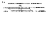
図3に示すように、車両検知装置100は、基準区間変化量判定にて、作成した距離画像を車両の進行方向における入場側に位置する基準区間aと、車両の出場側に位置する基準区間bと、基準区間aおよび基準区間bとの間に位置する基準区間cとに分割する。図5は、撮像画像を車両進行方向に分割と、分割された基準期間a、b及びcを示す図である。 As shown in FIG. 3, the vehicle detection device 100 determines, in the reference section change amount determination, the reference distance a that is created on the entrance side in the traveling direction of the vehicle and the reference section that is located on the entry side of the vehicle. b and a reference section c located between the reference section a and the reference section b. FIG. 5 is a diagram illustrating the division of the captured image in the vehicle traveling direction and the divided reference periods a, b, and c.
車両検知装置100は、制御部150の機能(f5)により距離画像における基準区間a内の画素毎の距離データと、背景距離画像における基準区間a内の画素毎の距離データ、すなわちレーザセンサ10で取得される背景距離データとの間の差分を計測する。車両検知装置100は、当該画素毎の差分を基準区間a内で合計した総和が閾値を超えた場合、距離画像の基準区間aをオン状態と判定し、当該閾値を超えない場合、距離画像の基準区間aをオフ状態と判定する。以下、基準区間bおよび基準区間cにおいても同様のステップによりオン/オフを判定する。(ステップST8)
車両検知装置100は、状態判定にて、制御部150の機能(f5)により判定された基準区間a、b及びcの各変化量(オン/オフ)判定結果に基づいて、状態番号を決定する。(ステップST9)
図6は、判定結果に基づいて割り振られた状態番号を示す図である。
The vehicle detection device 100 uses the function (f5) of the
The vehicle detection device 100 determines the state number based on the change (on / off) determination results of the reference sections a, b, and c determined by the function (f5) of the
FIG. 6 is a diagram illustrating a state number assigned based on the determination result.
図6に示すように、本実施形態では、例えば、基準区間a、b及びcがいずれもオフの場合にはS0(車両なし)、基準区間aのみがオンの場合にはS1(車両先頭)、基準区間bのみがオンの場合にはS2(車両後端)、基準区間cのみがオフの場合にはS4(後続車両先端および先行車両後端)、その他の状態をS3(車両側面)とする。 As shown in FIG. 6, in the present embodiment, for example, when all of the reference sections a, b, and c are off, S0 (no vehicle), and when only the reference section a is on, S1 (vehicle head). When only the reference section b is on, S2 (vehicle rear end), when only the reference section c is off, S4 (leading vehicle leading end and leading vehicle rear end), and other states are S3 (vehicle side). To do.
車両検知装置100は、状態番号の判定結果に基づいて、制御部150の機能(f6)により過去の状態番号の判定履歴と比較して遷移状態を判定する。図7は、車両が前進通過する場合の状態番号遷移を示す図である。図8は、車両が前進通過する場合の車両の存在位置と状態番号との関係を示す関係図である。
Based on the determination result of the state number, the vehicle detection device 100 determines the transition state by comparing with the determination history of the past state number by the function (f6) of the
図7及び図8に示すように、車両検知装置100は、例えば、状態番号の遷移“S0⇒S1⇒S3⇒S2⇒S0”を、車両の前進通過と判定する。画像フレーム毎の判定履歴としてはS0、S1、S1、S3、S3、S3、S3、S2、S2、S0…と状態番号が重複して現れ、判定履歴には重複を棄却して、状態番号変化時に履歴として登録する。車両検知装置100は、これら状態番号の遷移を予め登録された遷移のモデルと比較し、車両の通行を判定する。車両検知装置100は、逆方向についても状態番号の遷移”S0⇒S2⇒S3⇒S1⇒S0”で後進通過と判定が可能である。 As illustrated in FIGS. 7 and 8, the vehicle detection device 100 determines, for example, that the state number transition “S0⇒S1⇒S3⇒S2⇒S0” is a forward passage of the vehicle. As the determination history for each image frame, the state number overlaps with S0, S1, S1, S3, S3, S3, S3, S2, S2, S0... Sometimes register as history. The vehicle detection device 100 compares these state number transitions with a transition model registered in advance, and determines vehicle traffic. The vehicle detection device 100 can also determine that the vehicle has passed in the reverse direction with the state number transition “S0⇒S2⇒S3⇒S1⇒S0” in the reverse direction.
車両検知装置100は、上記過程を経て、台数計測処理にて、通過する車両を検出し、通過した台数を計測する(ステップST10)。車両検知装置100は、通過する車両の検出結果を出力する(ステップST11)。 Through the above process, the vehicle detection device 100 detects a passing vehicle in the number counting process and measures the number of passing vehicles (step ST10). The vehicle detection device 100 outputs a detection result of the passing vehicle (step ST11).
以上の構成によれば、実施形態の車両検知装置100は、上下に設置されたステレオカメラ20により、車両が通過する車線を撮像した各々の撮像画像から視差データを求め、視野内の物体との距離データを計算する。また、車両検知装置100は、背景距離データと視差データとの差分により、視野内の物体の存在を確認し、その位置関係を時刻毎に記録し、車両の遷移を判定して、車両の入出を検知することができる。 According to the above configuration, the vehicle detection device 100 according to the embodiment obtains the parallax data from each captured image obtained by capturing the lane through which the vehicle passes by the stereo cameras 20 installed above and below, and the object is within the field of view. Calculate distance data. Further, the vehicle detection device 100 confirms the presence of an object in the field of view based on the difference between the background distance data and the parallax data, records the positional relationship for each time, determines the vehicle transition, and enters and exits the vehicle. Can be detected.
以上、車両検知装置100の基本構成及び動作である。ここで、以下に示す実施例は、主に距離画像作成および基準区間変化量判定に関するもので、距離画像を正確に取得することにより、以降の車両台数計測精度を損なわないようにしている。 The basic configuration and operation of the vehicle detection device 100 have been described above. Here, the embodiment described below mainly relates to distance image creation and reference section change amount determination, and does not impair subsequent vehicle number measurement accuracy by accurately acquiring the distance image.
なお、以降の実施例では、車両が車線を前進通過する場合について記載する。 In the following embodiments, the case where the vehicle passes forward in the lane will be described.
(実施例1)
実施例1では、極端にテクスチャーの変化が乏しいパターンが入力画像として得られる場合について考慮する。
Example 1
In the first embodiment, a case where a pattern with extremely poor texture change is obtained as an input image is considered.
図9は、図3に示す対応点探索マッチング及びマッチング棄却処理の流れを示すフローチャートである。図10は、基準画像及び参照画像による対応点探索マッチングを示す図である。図11は、注目画素とその注目画素の周辺マッチングによる視差の算出過程を示す図である。 FIG. 9 is a flowchart showing the flow of matching point search matching and matching rejection processing shown in FIG. FIG. 10 is a diagram illustrating matching point search matching using a standard image and a reference image. FIG. 11 is a diagram illustrating a parallax calculation process based on a target pixel and peripheral matching of the target pixel.
図9に示すように、車両検知装置100の対応点探索マッチング(ステップST5)では、図10に示すように、エッジ強調された各々の撮像画像内から特徴点が表れている画素、すなわち図11に示す注目画素を決定し(ステップST51)、基準画像上の注目画素位置に矩形の注目領域ROI_Lを設定する(ステップST52)。また、車両検知装置100は、参照画像上にもROI_Lと同じ画素位置に同一サイズの領域ROI_Uを設定する(ステップST53)。車両検知装置100は、参照画像上に設定されたROI_Uの位置をずらして、ROI_Lの輝度と最も合う位置を探索する。車両検知装置100は、対応点マッチングスコア計測にて、ROI_UとROI_Lの差分を、例えば、SAD(Sum of Absolute Difference)等で計算し、計算した差分が最小値となる位置を求める(ステップST54)。これにより、車両検知装置100は、視差計測にて、ROI_Lの位置とROI_Uの位置から視差を計測する(ステップST55)。 As shown in FIG. 9, in the corresponding point search matching (step ST5) of the vehicle detection device 100, as shown in FIG. 10, pixels whose feature points appear from within each captured image with edge enhancement, that is, FIG. (Step ST51), and a rectangular region of interest ROI_L is set at the target pixel position on the reference image (step ST52). Moreover, the vehicle detection apparatus 100 sets the area | region ROI_U of the same size in the same pixel position as ROI_L also on a reference image (step ST53). The vehicle detection device 100 shifts the position of ROI_U set on the reference image and searches for a position that best matches the brightness of ROI_L. The vehicle detection apparatus 100 calculates the difference between ROI_U and ROI_L by, for example, SAD (Sum of Absolute Difference) or the like in the corresponding point matching score measurement, and obtains the position where the calculated difference becomes the minimum value (step ST54). . Thereby, the vehicle detection apparatus 100 measures parallax from the position of ROI_L and the position of ROI_U by parallax measurement (step ST55).
車両検知装置100では、原理的に、ステレオカメラ20の撮像画像から得られるテクスチャーのパターンの類似性を探索して、一致点を求めることにより、視差が適切な位置に求まる。 In principle, the vehicle detection device 100 searches for the similarity of the texture pattern obtained from the captured image of the stereo camera 20 and obtains the coincidence point, thereby obtaining the parallax at an appropriate position.
ところで、道路上の照度が極端に明るいまたは暗い場合、車両検知装置100は、視差を求める際のステレオカメラ20の撮像画像について、特に道路面でのテクスチャーのパターンが得にくくなり、マッチング誤差が発生する。これは、カメラから離れた解像度の粗い領域ほど発生し易い。さらに、これらの領域は1画素単位あたりの距離計測誤差が大きい。このため、マッチング誤差は、誤検出につながるリスクとして考えられる。 By the way, when the illuminance on the road is extremely bright or dark, the vehicle detection device 100 makes it difficult to obtain a texture pattern particularly on the road surface for the captured image of the stereo camera 20 when obtaining the parallax, and a matching error occurs. To do. This is more likely to occur in regions with a higher resolution that are farther from the camera. Further, these areas have large distance measurement errors per pixel unit. For this reason, the matching error is considered as a risk that leads to erroneous detection.
この誤検出を防ぐため、図9に示す車両検知装置100のマッチング棄却処理(ステップST6)では、制御部150の機能(f3)によりROI_L内の輝度から分散を計測する(ステップST61)。車両検知装置100は、計測した分散が閾値以下となった場合、誤マッチングのリスクが発生するとし、視差の計測対象より棄却する(ステップS63)。また、車両検知装置100は、ROI_L内の輝度から計測した分散だけでなく、ROI_U内の輝度による分散についても同様に計測して(ステップS62)、閾値以下の場合、同様に、視差の計測対象より棄却する(ステップS63)。
In order to prevent this erroneous detection, in the matching rejection process (step ST6) of the vehicle detection device 100 shown in FIG. 9, the function (f3) of the
以上の処理により、車両検知装置100は、極端にテクスチャーの変化が乏しいパターンが入力画像として得られる場合においても、対応点探索時の誤マッチングを防ぎ、正確な距離を計測することができる。 With the above processing, the vehicle detection device 100 can measure an accurate distance by preventing erroneous matching when searching for corresponding points even when a pattern with extremely poor texture change is obtained as an input image.
(実施例2)
実施例2では、ステレオカメラの輝度範囲の上限及び下限を超える画素が多い低品質な画像を用いる場合について考慮する。
(Example 2)
In the second embodiment, a case where a low quality image having many pixels exceeding the upper limit and the lower limit of the luminance range of the stereo camera is used is considered.
図12は、図10に示す基準画像及び参照画像の輝度範囲を検証する機能を有する対応点探索マッチングの過程を示すフローチャートである。 FIG. 12 is a flowchart showing a corresponding point search matching process having a function of verifying the luminance ranges of the standard image and the reference image shown in FIG.
図12に示すように、車両検知装置100は、実施例1と同様に、基準画像上の注目画素位置に矩形の注目領域ROI_Lを設定する(ステップST52)。また、車両検知装置100は、参照画像上にもROI_Lと同じ画素位置に同一サイズの領域ROI_Uを設定する(ステップST53)。車両検知装置100は、参照画像上に設定されたROI_Uの位置をずらして、ROI_Lの輝度と最も合う位置を探索する。車両検知装置100は、対応点マッチングスコア計測にて、ROI_UとROI_Lの差分を、例えば、SAD(Sum of Absolute Difference)等で計算し、計算した差分が最小値となる位置を求める(ステップST54)。これにより、車両検知装置100は、視差計測にて、ROI_Lの位置とROI_Uの位置から視差を計測する(ステップST55)。ここで、車両検知装置100は、対応点探索マッチングにて、計測された視差に対応する領域ROI_U内の画素の輝度が予め設定された輝度範囲の上限および下限の範囲内かを判定する(ステップST56)。このとき、画素の輝度が上限を超える場合、白とびのリスクが発生している可能性がある。また、画素の輝度が下限を下回る場合、黒つぶれのリスクが発生している可能性がある。車両検知装置100は、予め設定された輝度範囲外となった画素の視差を計測対象より棄却する。 As illustrated in FIG. 12, the vehicle detection device 100 sets a rectangular region of interest ROI_L at the pixel position of interest on the reference image, similarly to the first embodiment (step ST52). Moreover, the vehicle detection apparatus 100 sets the area | region ROI_U of the same size in the same pixel position as ROI_L also on a reference image (step ST53). The vehicle detection device 100 shifts the position of ROI_U set on the reference image and searches for a position that best matches the brightness of ROI_L. The vehicle detection apparatus 100 calculates the difference between ROI_U and ROI_L by, for example, SAD (Sum of Absolute Difference) or the like in the corresponding point matching score measurement, and obtains the position where the calculated difference becomes the minimum value (step ST54). . Thereby, the vehicle detection apparatus 100 measures parallax from the position of ROI_L and the position of ROI_U by parallax measurement (step ST55). Here, the vehicle detection device 100 determines whether or not the luminance of the pixels in the region ROI_U corresponding to the measured parallax is within the upper and lower limits of the preset luminance range by the corresponding point search matching (step) ST56). At this time, if the luminance of the pixel exceeds the upper limit, there is a possibility that an overexposure risk has occurred. Further, when the luminance of the pixel is lower than the lower limit, there is a possibility that a blackout risk has occurred. The vehicle detection apparatus 100 rejects the parallax of the pixels that are out of the preset luminance range from the measurement target.
ここで、車両検知装置100は、カメラの光量を制御する機構がカメラ間で同期していない場合、映像中の同一地点にて片方の画像のみ白とび(上限を越える輝度が多数)してしまう状況も考えられる。このため、実施例2の車両検知装置100では、単純に注目画素毎に判定を行う。 Here, if the mechanism for controlling the amount of light of the cameras is not synchronized between the cameras, the vehicle detection device 100 will be overexposed (a large number of luminances exceeding the upper limit) at only one image at the same point in the video. The situation is also conceivable. For this reason, in the vehicle detection device 100 according to the second embodiment, the determination is simply performed for each pixel of interest.
以上の処理により、車両検知装置100は、ステレオカメラの輝度範囲の上限及び下限を超える画素が多い低品質な画像を要因とする対応点探索の誤マッチングを防ぎ、正確な距離を計測することができる。 With the above processing, the vehicle detection device 100 can prevent an erroneous matching of corresponding point search caused by a low-quality image having many pixels exceeding the upper limit and lower limit of the luminance range of the stereo camera, and can measure an accurate distance. it can.
(実施例3)
実施例3では、道路面に日光の強い照り返し部分と影部分とが混在している場合について考慮する。
(Example 3)
In the third embodiment, a case where a reflection portion and a shadow portion with strong sunlight are mixed on the road surface is considered.
道路面に日光の強い照り返し部分と影部分とが混在していると、その境界部分のエッジ変化が顕著となり、撮像画像内に輝度の高い領域と影の暗い領域が混在してしまう場合がある。この場合の対応点探索マッチング結果は、エッジ変化が顕著な境界部分寄りに誤差が発生する傾向がある。 If there is a strong reflection of sunlight and shadows on the road surface, edge changes at the borders will become noticeable, and areas with high brightness and dark shadows may exist in the captured image. . In the corresponding point search matching result in this case, an error tends to occur near the boundary portion where the edge change is remarkable.
この誤差を防ぐため、図9に示すように、車両検知装置100は、実施例1と同様に、マッチング棄却処理にて、基準画像上の注目領域ROI_L内の輝度より分散を計測する(ステップST61)。車両検知装置100では、エッジ変化が顕著となっている場合、マッチング棄却処理の視差・分散による判定(ステップST63)にて、ROI_L内の輝度が大きくなるため、分散が閾値を超えるかを判定する。また、車両検知装置100では、撮像画像の解像度が低い場合、誤マッチングが発生し易くなるため、注目領域ROI_Lと領域ROI_Uとの視差を判定し、閾値以下であるかを判定する。 In order to prevent this error, as shown in FIG. 9, the vehicle detection device 100 measures the variance from the luminance in the attention area ROI_L on the reference image in the matching rejection process as in the first embodiment (step ST61). ). In the vehicle detection device 100, when the edge change is significant, in the determination based on the parallax / dispersion of the matching rejection process (step ST63), since the luminance in the ROI_L is increased, it is determined whether the variance exceeds the threshold value. . Further, in the vehicle detection device 100, when the resolution of the captured image is low, mismatching is likely to occur. Therefore, the parallax between the attention area ROI_L and the area ROI_U is determined, and it is determined whether it is equal to or less than the threshold value.
上記2つの判定条件を満たしている画素の視差については、計測対象より棄却する。 The parallax of the pixel that satisfies the above two determination conditions is rejected from the measurement target.
以上の処理により、車両検知装置100は、撮像画像内にテクスチャーの詳細な情報とのマッチングを阻害する、影境界部分等の極端なコントラストが存在することによる誤マッチングを事前に防ぎ、正確な距離を計測することができる。 With the above processing, the vehicle detection device 100 prevents in advance false matching due to the presence of extreme contrast such as a shadow boundary portion that hinders matching with detailed texture information in the captured image, and the accurate distance Can be measured.
(実施例4)
実施例4では、自動車のボンネット部分等、テクスチャー情報が乏しい場合について考慮する。
Example 4
In Example 4, a case where texture information is scarce, such as a hood part of an automobile, is considered.
車両検知装置100は、対応点探索マッチングにて、基準画像上の注目領域ROI_Lを設定する。車両検知装置100は、ROI_L内の注目画素を中心にROI_L内画素を昇順に並べ、閾値以下の近接した値が存在する場合、誤マッチングが発生するリスクを考慮して、その近接した画素の視差を計測対象から棄却する。 The vehicle detection device 100 sets a region of interest ROI_L on the reference image by corresponding point search matching. The vehicle detection device 100 arranges the pixels in the ROI_L in ascending order centering on the target pixel in the ROI_L, and when there is a close value that is equal to or less than the threshold, the parallax between the adjacent pixels is considered in consideration of the risk of erroneous matching. Is rejected from the measurement target.
以上の処理により、車両検知装置100は、車両のボンネット部等、テクスチャーが乏しい場合において、誤マッチングを事前に防ぎ、視差を元に正確な距離を計測することができる。 With the above processing, the vehicle detection device 100 can prevent erroneous matching in advance and measure an accurate distance based on the parallax when the texture of the vehicle hood or the like is poor.
(実施例5)
実施例5では、検知対象の視野の一部に障害物が継続して観測されるような不具合が発生した場合について考慮する、
図13は、基準区間で不感領域を設定する過程を説明するための図である。
(Example 5)
In Example 5, consider the case where a failure occurs such that an obstacle is continuously observed in a part of the visual field to be detected,
FIG. 13 is a diagram for explaining a process of setting a dead area in the reference section.
図13に示すように、車両検知装置100は、例えば、カメラのレンズに泥や雨粒が付着する等、センサに何らかの不具合が発生し、視野の一部に障害物が継続して観測される場合について考慮する。 As shown in FIG. 13, the vehicle detection device 100 has a case in which some trouble occurs in the sensor such as mud or raindrops adhering to the camera lens, and an obstacle is continuously observed in a part of the field of view. Consider.
車両検知装置100は、基準区間変化量判定にて、計測された差分から基準区間の変化量を各々測定する。車両検知装置100は、基準区間毎に変化量(オン/オフ)を判定する。車両検知装置100は、オンと判定する場合、その位置での連続オン判定回数を履歴カウンタに保存する。車両検知装置100は、履歴カウンタに保存される連続オン判定回数が設定値に到達したか否かを判定し、到達した場合、不感領域フラグを立てる。次に、車両検知装置100は、不感領域フラグを参照し、連続してオンとなっていた区間については、変化量の判定結果をオンからオフへと置き換える。置き換えは(1)進入側、(2)中央エリア及び(3)退出側の3つのエリアで行われる。 The vehicle detection apparatus 100 measures the change amount of the reference section from the measured difference in the reference section change amount determination. The vehicle detection device 100 determines the amount of change (on / off) for each reference section. When determining that the vehicle is ON, the vehicle detection device 100 stores the number of continuous ON determinations at that position in the history counter. The vehicle detection device 100 determines whether or not the number of continuous ON determinations stored in the history counter has reached a set value, and when it reaches, sets a dead area flag. Next, the vehicle detection apparatus 100 refers to the insensitive area flag and replaces the change amount determination result from on to off for a section that is continuously on. Replacement takes place in three areas: (1) entry side, (2) central area, and (3) exit side.
なお、車両検知装置100は、基準区間の変化量がオンからオフへと変化した際に履歴カウンタおよび不感領域を初期化し、元の状態に戻す。このとき、車両検知装置100は、一度にゼロクリアするのではなく、連続してnフレーム以上オフであった場合に実行する等の条件を付与してもよい。 Note that the vehicle detection device 100 initializes the history counter and the insensitive area when the amount of change in the reference section changes from on to off, and restores the original state. At this time, the vehicle detection device 100 may give a condition such as executing it when it is continuously off for n frames or more, instead of clearing zero at a time.
以上の処理により、車両検知装置100は、検知対象の視野の一部に障害物が継続して観測されるような不具合が発生した場合、不感領域を設定し、不具合が発生している領域の変化量の判定結果をオフすることにより、高精度な車両台数計測機能を提供することができる。 With the above processing, the vehicle detection device 100 sets the insensitive area when a failure occurs such that an obstacle is continuously observed in a part of the field of view of the detection target. By turning off the determination result of the change amount, it is possible to provide a highly accurate vehicle number measuring function.
(実施例6)
実施例6では、雨や雪等の比較的小さな飛来物が視野内に存在した場合について考慮する。
(Example 6)
In the sixth embodiment, a case where a relatively small flying object such as rain or snow is present in the field of view will be considered.
図14は、基準区間変化量判定における連結成分の面積・形状判定を有するフローチャートである。 FIG. 14 is a flowchart including the area / shape determination of the connected component in the reference interval change amount determination.
車両検知装置100は、雪や大粒の雨等により、障害物の外輪郭が基準高さを越えて観測された場合、視野内に点状の物体として多数捉えられ、その数量によっては誤検知のリスクがある。 When the outer contour of an obstacle is observed beyond the reference height due to snow, large rain, or the like, the vehicle detection device 100 is captured as many point-like objects in the field of view, and depending on the quantity, erroneous detection may occur. There is a risk.
この誤検知を防ぐため、図14に示すように、車両検知装置100では、距離計測(ステップST7)にて取得した距離画像に含まれる距離データとレーザセンサ10から取得される背景距離データとの間の差分を計測する(ステップST81)。車両検知装置100は、計測された差分が、道路面を基準とした基準高さ以上であるかを比較し(ステップST82)、基準高さ以下の差分は計測しない。車両検知装置100は、計測された差分が基準高さ以上である画素の数を計測する(ステップST83)。車両検知装置100は、計測された画素間の連結性を考慮したラベリング(連結成分抽出)を行い(ステップST84)、ラベリングされた画素の面積(画素の数に相当)を判定し(ステップST85)、一定面積以上のものについては車両候補として判定し、一定面積以下のものについてはノイズとして判定する。車両検知装置100は、ノイズと判定された画素については、基準高さ以上の距離を基準高さ以下の距離へと置き換える(ステップST86)。車両検知装置100は、再び基準高さ超えの画素の数を計測し(ステップST87)、基準区間毎に、オン/オフの組み合わせによる状態判定を行う(ステップST9)。このとき、ラベルの形状を参照し、面積の他の情報として、ラベル毎の縦方向、横方向、斜め方向の形状分類にてノイズ判定を行う条件を付与する。
In order to prevent this erroneous detection, as shown in FIG. 14, in the vehicle detection device 100, the distance data included in the distance image acquired in the distance measurement (step ST7) and the background distance data acquired from the
以上の処理により、車両検知装置100は、雨や雪等の比較的小さな飛来物が視野内に存在した場合、飛来物の外輪郭の情報を取得し、その占有面積を判定してノイズ棄却を行うことにより、天候や照度の外乱に依存せず、精度良く障害物を計測することができる。 With the above processing, when a relatively small flying object such as rain or snow is present in the field of view, the vehicle detection device 100 acquires information on the outer contour of the flying object, determines its occupied area, and rejects noise. By doing so, it is possible to accurately measure an obstacle without depending on disturbance of weather or illuminance.
(実施例7)
実施例7では、積雪等により道路面を基準とした基準高さが高くなっている場合について考慮する。
(Example 7)
In the seventh embodiment, a case where the reference height based on the road surface is increased due to snow accumulation or the like will be considered.
図15は、基準高さの2段階切り替え機能を有するフローチャートである。 FIG. 15 is a flowchart having a two-step switching function of the reference height.
図15に示すように、車両検知装置100は、基準区間変化量判定にて、画素毎の距離が基準高さを超える画素を計測する際に、基準高さを標準仕様のものと標準仕様に設定値を加算したより高めの仕様のものと2種類を予め保持しておく。車両検知装置100は、基準区間変化量判定にて、差分を計測した後、基準区間の変化量を計測する前に、状態判定記録(ステップST89)から、状態番号を参照する(ステップST88)。車両検知装置100は、障害物の検出状態がない場合、基準高さの高め仕様を適用する。その高め仕様基準を超える画素が増え、基準区間についてオン判定された場合、障害物の検出ありとなる状態番号が変化する。以降も、車両検知装置100は、状態番号を参照して、基準区間変化量判定にて、標準仕様の基準高さを使用し、同様に標準仕様の基準高さを越える画素を計測して、変化量を計測する。その標準仕様基準を超える画素が減り、基準区間についてオフ判定された場合は障害物なしとなり、状態番号が変化する。状態番号が変化し、障害物の検出状態がない場合に戻った場合には、再び高め仕様基準高さを適用する 。 As shown in FIG. 15, the vehicle detection device 100 changes the reference height between the standard specification and the standard specification when measuring pixels whose distance per pixel exceeds the reference height in the reference section change amount determination. Two types having higher specifications and added set values are stored in advance. The vehicle detection apparatus 100 refers to the state number from the state determination record (step ST89) after measuring the difference in the reference section change amount determination and before measuring the change amount of the reference section (step ST88). When there is no obstacle detection state, the vehicle detection device 100 applies the specification with a higher reference height. When the number of pixels exceeding the higher specification standard increases and the ON determination is made for the reference section, the state number where an obstacle is detected changes. Thereafter, the vehicle detection apparatus 100 refers to the state number, uses the standard height of the standard specification in the determination of the change amount of the standard section, and similarly measures pixels exceeding the standard height of the standard specification, Measure the amount of change. If the number of pixels exceeding the standard specification is reduced and the reference section is determined to be off, there is no obstacle and the state number changes. If the status number changes and there is no obstacle detection status, it will be raised again and the specified reference height will be applied.
また、車両検知装置100は、基準高さを多段階用意し、状態番号に依存せず、カメラから遠ざかるにつれ、基準高さ(標準+設定値)における設定値の値を大きくして、基準区間の変化量を計測する。 In addition, the vehicle detection apparatus 100 prepares a plurality of reference heights, and does not depend on the state number, and increases the set value at the reference height (standard + set value) as the distance from the camera increases. Measure the amount of change.
以上の処理により、車両検知装置100は、路面上に突発的に障害物を検知した場合においても、車両サイズを考慮した高めの基準で設定された閾値を適用することにより、耐性が向上する。したがって、車両検知装置100は、落下物にも影響されず、車両の進入時に精度良く障害物を計測することができる。 By the above processing, even when the vehicle detection device 100 detects an obstacle suddenly on the road surface, the tolerance is improved by applying the threshold set with a higher standard considering the vehicle size. Therefore, the vehicle detection device 100 is not affected by a falling object and can accurately measure an obstacle when the vehicle enters.
(実施例8)
実施例8では、
図16は、奥行き方向の背景距離について2段階切り替え機能を有するフローチャートである。
(Example 8)
In Example 8,
FIG. 16 is a flowchart having a two-stage switching function for the background distance in the depth direction.
図16に示すように、車両検知装置100は、基準区間変化量判定において、取得した距離画像に含まれる距離データとレーザセンサ10から取得される背景距離データとの差分を計測する。
As shown in FIG. 16, the vehicle detection device 100 measures the difference between the distance data included in the acquired distance image and the background distance data acquired from the
車両検知装置100は、撮像領域を、車両の進行方向とカメラからの距離(奥行き)方向の2軸で設定する。すなわち、撮像領域は、カメラからの距離(奥行き)方向について、閾値に相当する境界線を設定すると、境界線の手前側と奥側の2領域に再分割される。手前側は、通常、道路が背景として映っており、手前側を走行する車両との距離と、道路部分の背景距離との差分より道路面からの高さを計測する。一方、奥側は道路が背景とは限らず、料金所に見られるようなレーン間を仕切る壁であったり、または背景が隣の通路だったりと不定である。したがって、車両検知装置100は、奥側は仮想的な道路(壁)を背景として設定し、奥側を走行する車両との距離と、仮想的な道路(壁)距離との差分より、障害物の高さを計測する。 The vehicle detection device 100 sets an imaging region with two axes, that is, a traveling direction of the vehicle and a distance (depth) direction from the camera. That is, the imaging region is subdivided into two regions on the near side and the far side of the boundary line when a boundary line corresponding to the threshold is set in the distance (depth) direction from the camera. On the near side, the road is usually reflected as the background, and the height from the road surface is measured from the difference between the distance from the vehicle traveling on the near side and the background distance of the road portion. On the other hand, the road is not limited to the background, and it is uncertain that the road is a wall that partitions lanes as seen at a toll booth, or that the background is an adjacent passage. Therefore, the vehicle detection device 100 sets the back side with a virtual road (wall) as a background, and determines the obstacle from the difference between the distance from the vehicle traveling on the back side and the virtual road (wall) distance. Measure the height.
車両検知装置100は、各々計算された高さについて、予め用意された基準高さの仕様基準を超える画素を計測し、基準区間(進入・停留・退出の部分)のオン/オフ判定を行う(ステップST810)。 For each calculated height, the vehicle detection device 100 measures pixels that exceed the specification standard of a reference height prepared in advance, and performs on / off determination of a reference section (entrance / stop / exit part) ( Step ST810).
以上の処理により、車両検知装置100は、車両が通路のどの位置を走行しても、安定して基準区間のオン/オフ判定が得られ、車両の通過を精度良く計測することができる。 With the above processing, the vehicle detection device 100 can stably determine the on / off of the reference section regardless of the position of the passage of the vehicle, and can accurately measure the passage of the vehicle.
以上、実施形態によれば、図9に示す車両検知装置100のマッチング棄却処理では、ROI_L内の輝度から分散を計測する。車両検知装置100は、計測した分散が閾値以下となった場合、誤マッチングのリスクが発生するとし、視差の計測対象より棄却する。また、車両検知装置100は、ROI_L内の輝度から計測した分散だけでなく、ROI_U内の輝度による分散についても同様に計測して、閾値以下の場合、同様に、視差の計測対象より棄却する。これにより、車両検知装置100は、極端にテクスチャーの変化が乏しいパターンが入力画像として得られる場合においても、対応点探索時の誤マッチングを防ぎ、正確な距離を計測することができる。 As described above, according to the embodiment, in the matching rejection process of the vehicle detection device 100 illustrated in FIG. 9, the variance is measured from the luminance in the ROI_L. The vehicle detection device 100 rejects the parallax measurement target if a risk of mismatching occurs when the measured variance falls below the threshold. Further, the vehicle detection device 100 similarly measures not only the variance measured from the luminance in the ROI_L but also the variance due to the luminance in the ROI_U, and similarly rejects it from the parallax measurement target when it is equal to or less than the threshold. As a result, the vehicle detection device 100 can prevent an erroneous matching at the time of searching for a corresponding point and measure an accurate distance even when a pattern with extremely poor texture change is obtained as an input image.
したがって、本実施形態の車両検知装置は、ステレオカメラの採用において、光学条件の変化に影響されず、撮影画像から車両の入出を高精度に検知することができる。 Therefore, the adoption of the stereo camera allows the vehicle detection device of the present embodiment to detect the entry / exit of the vehicle from the captured image with high accuracy without being affected by the change in the optical conditions.
なお、上記レーザセンサ10は、レーザビームをスキャンし、反射したレーザビームを受波した受波データを車両検知装置100に送出するセンサとしてもよい。この場合、車両検知装置100は、受波データから距離データを算出する機能を備える必要がある。
The
以上、本発明の実施形態を説明したが、この実施形態は、例として提示したものであり、発明の範囲を限定することは意図していない。この実施形態は、その他の様々な形態で実施されることが可能であり、発明の要旨を逸脱しない範囲で、種々の省略、置き換え、変更を行うことができる。この実施形態やその変形は、発明の範囲や要旨に含まれると同様に、特許請求の範囲に記載された発明とその均等の範囲に含まれるものである。 As mentioned above, although embodiment of this invention was described, this embodiment is shown as an example and is not intending limiting the range of invention. This embodiment can be implemented in various other forms, and various omissions, replacements, and changes can be made without departing from the spirit of the invention. This embodiment and its modifications are included in the scope of the present invention and the gist thereof, and are also included in the invention described in the claims and the equivalent scope thereof.
10…レーザセンサ、20…ステレオカメラ、30…ETCシステム、100…車両検知装置、110…表示部、120…ユーザインタフェース、130…記憶部、140…ネットワークインタフェース、150…制御部。
DESCRIPTION OF
Claims (9)
前記各々の撮像画像について、車両の上下方向に延びる線上に存在するエッジに対し、エッジ強調を行うエッジ強調手段と、
前記エッジ強調された各々の撮像画像から視差データを画素毎に計測する視差データ計測手段と、
前記各々の撮像画像内の画素の輝度の分散を求め、その結果より前記画素毎の視差データを選択的に棄却する視差データ棄却手段と、
前記視差データから前記ステレオカメラと撮像対象との間の距離を示す距離データを画素毎に計測する距離データ計測手段と、
前記距離を画素毎に有する距離画像を作成する距離画像作成手段と、
前記車両の進行方向に前記距離画像を複数の領域に分割して複数の基準区間を形成し、複数の基準区間それぞれで、予め車両のない状態で計測される背景距離データと前記距離データ計測手段で車両の入出時に指定時刻毎に計測される距離データとの差分を求め、前記基準区間毎に差分の変化量を時刻毎に求め、前記基準区間毎に差分の変化量を閾値と比較することで、物体の有無に対応する状態を時刻毎に判定する状態判定手段と、
前記時刻毎の状態判定を保持し、前記車両の遷移を判定し、前記車両の入出を検知する入出検知手段と
を具備することを特徴とする車両検知装置。 A vehicle detecting apparatus for detecting a vehicle into and out of the inside of the field of view of the stereo camera based on each of images captured by the stereo camera,
The captured images of the respective, relative to edge existing on a line extending in the vertical direction of the vehicle, and edge enhancement means for performing edge enhancement,
Parallax data measuring means for measuring parallax data for each pixel from each of the edge-enhanced captured images;
Dispersion of luminance of the pixels in each captured image, parallax data rejecting means for selectively rejecting the disparity data for each pixel from the result,
Distance data measuring means for measuring, for each pixel, distance data indicating a distance between the stereo camera and the imaging target from the parallax data;
A distance image creating means for creating a distance image having the distance for each pixel;
The distance image is divided into a plurality of regions in the traveling direction of the vehicle to form a plurality of reference sections, and each of the plurality of reference sections is measured in advance in the absence of a vehicle and the distance data measuring means. The difference between the distance data measured at a specified time when the vehicle enters and exits is obtained, the change amount of the difference is obtained for each reference section for each time, and the change amount of the difference is compared with a threshold value for each reference section. Then, state determination means for determining the state corresponding to the presence or absence of the object for each time,
A vehicle detection apparatus comprising: state determination for each time, determination of transition of the vehicle, and detection of entry / exit of the vehicle.
Priority Applications (3)
| Application Number | Priority Date | Filing Date | Title |
|---|---|---|---|
| JP2012220429A JP6139088B2 (en) | 2012-10-02 | 2012-10-02 | Vehicle detection device |
| PCT/JP2013/070191 WO2014054328A1 (en) | 2012-10-02 | 2013-07-25 | Vehicle detection apparatus |
| IN3315DEN2015 IN2015DN03315A (en) | 2012-10-02 | 2013-07-25 |
Applications Claiming Priority (1)
| Application Number | Priority Date | Filing Date | Title |
|---|---|---|---|
| JP2012220429A JP6139088B2 (en) | 2012-10-02 | 2012-10-02 | Vehicle detection device |
Publications (2)
| Publication Number | Publication Date |
|---|---|
| JP2014074939A JP2014074939A (en) | 2014-04-24 |
| JP6139088B2 true JP6139088B2 (en) | 2017-05-31 |
Family
ID=50434664
Family Applications (1)
| Application Number | Title | Priority Date | Filing Date |
|---|---|---|---|
| JP2012220429A Expired - Fee Related JP6139088B2 (en) | 2012-10-02 | 2012-10-02 | Vehicle detection device |
Country Status (3)
| Country | Link |
|---|---|
| JP (1) | JP6139088B2 (en) |
| IN (1) | IN2015DN03315A (en) |
| WO (1) | WO2014054328A1 (en) |
Families Citing this family (8)
| Publication number | Priority date | Publication date | Assignee | Title |
|---|---|---|---|---|
| DE102014106854A1 (en) * | 2014-05-15 | 2016-01-28 | Odos Imaging Ltd. | Imaging system and method for monitoring a field of view |
| KR101655620B1 (en) * | 2014-12-18 | 2016-09-07 | 현대자동차주식회사 | Apparatus and Method for Measuring Distance in Vehicle |
| WO2019065218A1 (en) * | 2017-09-28 | 2019-04-04 | 株式会社小糸製作所 | Sensor system |
| US11538257B2 (en) | 2017-12-08 | 2022-12-27 | Gatekeeper Inc. | Detection, counting and identification of occupants in vehicles |
| US10867193B1 (en) | 2019-07-10 | 2020-12-15 | Gatekeeper Security, Inc. | Imaging systems for facial detection, license plate reading, vehicle overview and vehicle make, model, and color detection |
| US11196965B2 (en) | 2019-10-25 | 2021-12-07 | Gatekeeper Security, Inc. | Image artifact mitigation in scanners for entry control systems |
| CN112158134A (en) * | 2020-09-23 | 2021-01-01 | 中国第一汽车股份有限公司 | Vehicle-to-rear vehicle road condition information prompting system and prompting method thereof |
| CN117496387A (en) * | 2022-07-22 | 2024-02-02 | 顺丰科技有限公司 | Vehicle arrival/departure detection method, device, equipment and storage medium |
Family Cites Families (4)
| Publication number | Priority date | Publication date | Assignee | Title |
|---|---|---|---|---|
| JP3605955B2 (en) * | 1996-07-31 | 2004-12-22 | オムロン株式会社 | Vehicle identification device |
| JP3272696B2 (en) * | 1999-07-30 | 2002-04-08 | 富士重工業株式会社 | Outside monitoring device with fail-safe function |
| JP4363295B2 (en) * | 2004-10-01 | 2009-11-11 | オムロン株式会社 | Plane estimation method using stereo images |
| JP5057750B2 (en) * | 2006-11-22 | 2012-10-24 | 株式会社東芝 | Toll collection system |
-
2012
- 2012-10-02 JP JP2012220429A patent/JP6139088B2/en not_active Expired - Fee Related
-
2013
- 2013-07-25 WO PCT/JP2013/070191 patent/WO2014054328A1/en active Application Filing
- 2013-07-25 IN IN3315DEN2015 patent/IN2015DN03315A/en unknown
Also Published As
| Publication number | Publication date |
|---|---|
| IN2015DN03315A (en) | 2015-10-09 |
| JP2014074939A (en) | 2014-04-24 |
| WO2014054328A1 (en) | 2014-04-10 |
Similar Documents
| Publication | Publication Date | Title |
|---|---|---|
| JP6139088B2 (en) | Vehicle detection device | |
| US10753758B2 (en) | Top-down refinement in lane marking navigation | |
| US11087148B2 (en) | Barrier and guardrail detection using a single camera | |
| US9047518B2 (en) | Method for the detection and tracking of lane markings | |
| JP5867273B2 (en) | Approaching object detection device, approaching object detection method, and computer program for approaching object detection | |
| AU2015352462B2 (en) | Method of controlling a traffic surveillance system | |
| CN109284674B (en) | Method and device for determining lane line | |
| US7046822B1 (en) | Method of detecting objects within a wide range of a road vehicle | |
| CN101510356B (en) | Video detection system and data processing device thereof, video detection method | |
| KR100969995B1 (en) | System of traffic conflict decision for signalized intersections using image processing technique | |
| RU2636120C2 (en) | Three-dimensional object detecting device | |
| US9965690B2 (en) | On-vehicle control device | |
| CN104508722A (en) | Vehicle-mounted surrounding environment recognition device | |
| WO2013018708A1 (en) | Vehicle detection device and vehicle detection method | |
| KR20030080285A (en) | Apparatus and method for queue length of vehicle to measure | |
| Lin et al. | Lane departure and front collision warning using a single camera | |
| CN103164685B (en) | Vehicle lamp detection method and car light detection device | |
| JP6818626B2 (en) | Vehicle type discrimination device, vehicle type discrimination method, and vehicle type discrimination system | |
| JP4071527B2 (en) | Diagnostic imaging equipment | |
| JP2002008019A (en) | Railway track recognition device and rolling stock using railway track recognition device | |
| JP2013134667A (en) | Vehicle detection device | |
| JP2014067320A (en) | Stereo camera device | |
| JP2014010771A (en) | Vehicle detection device | |
| Nakayama et al. | Robust vehicle detection under poor environmental conditions for rear and side surveillance | |
| CN103909881A (en) | Environment information detection system and environment information detection method |
Legal Events
| Date | Code | Title | Description |
|---|---|---|---|
| A621 | Written request for application examination |
Free format text: JAPANESE INTERMEDIATE CODE: A621 Effective date: 20150306 |
|
| A131 | Notification of reasons for refusal |
Free format text: JAPANESE INTERMEDIATE CODE: A131 Effective date: 20160315 |
|
| A521 | Written amendment |
Free format text: JAPANESE INTERMEDIATE CODE: A523 Effective date: 20160513 |
|
| A131 | Notification of reasons for refusal |
Free format text: JAPANESE INTERMEDIATE CODE: A131 Effective date: 20161018 |
|
| A521 | Written amendment |
Free format text: JAPANESE INTERMEDIATE CODE: A523 Effective date: 20161101 |
|
| TRDD | Decision of grant or rejection written | ||
| A01 | Written decision to grant a patent or to grant a registration (utility model) |
Free format text: JAPANESE INTERMEDIATE CODE: A01 Effective date: 20170404 |
|
| A61 | First payment of annual fees (during grant procedure) |
Free format text: JAPANESE INTERMEDIATE CODE: A61 Effective date: 20170427 |
|
| R151 | Written notification of patent or utility model registration |
Ref document number: 6139088 Country of ref document: JP Free format text: JAPANESE INTERMEDIATE CODE: R151 |
|
| LAPS | Cancellation because of no payment of annual fees |