JP6138823B2 - Method for forming fibers from vitrifiable materials - Google Patents
Method for forming fibers from vitrifiable materials Download PDFInfo
- Publication number
- JP6138823B2 JP6138823B2 JP2014549516A JP2014549516A JP6138823B2 JP 6138823 B2 JP6138823 B2 JP 6138823B2 JP 2014549516 A JP2014549516 A JP 2014549516A JP 2014549516 A JP2014549516 A JP 2014549516A JP 6138823 B2 JP6138823 B2 JP 6138823B2
- Authority
- JP
- Japan
- Prior art keywords
- furnace
- molten
- vitrifiable material
- dam
- vitrifiable
- Prior art date
- Legal status (The legal status is an assumption and is not a legal conclusion. Google has not performed a legal analysis and makes no representation as to the accuracy of the status listed.)
- Active
Links
- 239000000463 material Substances 0.000 title claims description 76
- 238000000034 method Methods 0.000 title claims description 33
- 239000000835 fiber Substances 0.000 title claims description 30
- UQSXHKLRYXJYBZ-UHFFFAOYSA-N Iron oxide Chemical compound [Fe]=O UQSXHKLRYXJYBZ-UHFFFAOYSA-N 0.000 claims description 24
- 238000009826 distribution Methods 0.000 claims description 22
- 239000002994 raw material Substances 0.000 claims description 16
- 229910052751 metal Inorganic materials 0.000 claims description 11
- 239000002184 metal Substances 0.000 claims description 11
- PNEYBMLMFCGWSK-UHFFFAOYSA-N aluminium oxide Inorganic materials [O-2].[O-2].[O-2].[Al+3].[Al+3] PNEYBMLMFCGWSK-UHFFFAOYSA-N 0.000 claims description 7
- 239000012809 cooling fluid Substances 0.000 claims description 6
- ZOKXTWBITQBERF-UHFFFAOYSA-N Molybdenum Chemical compound [Mo] ZOKXTWBITQBERF-UHFFFAOYSA-N 0.000 claims description 5
- 229910052750 molybdenum Inorganic materials 0.000 claims description 5
- 239000011733 molybdenum Substances 0.000 claims description 5
- 239000002557 mineral fiber Substances 0.000 claims description 3
- 238000004031 devitrification Methods 0.000 claims description 2
- 238000004017 vitrification Methods 0.000 claims description 2
- 238000000465 moulding Methods 0.000 claims 1
- 239000012768 molten material Substances 0.000 description 23
- 239000011521 glass Substances 0.000 description 10
- 230000004927 fusion Effects 0.000 description 7
- 238000007493 shaping process Methods 0.000 description 7
- XLYOFNOQVPJJNP-UHFFFAOYSA-N water Substances O XLYOFNOQVPJJNP-UHFFFAOYSA-N 0.000 description 7
- 238000004519 manufacturing process Methods 0.000 description 6
- 239000011819 refractory material Substances 0.000 description 6
- 239000000758 substrate Substances 0.000 description 5
- 229910000831 Steel Inorganic materials 0.000 description 4
- 238000010521 absorption reaction Methods 0.000 description 4
- 239000007787 solid Substances 0.000 description 4
- 239000010959 steel Substances 0.000 description 4
- XEEYBQQBJWHFJM-UHFFFAOYSA-N Iron Chemical compound [Fe] XEEYBQQBJWHFJM-UHFFFAOYSA-N 0.000 description 3
- VYPSYNLAJGMNEJ-UHFFFAOYSA-N Silicium dioxide Chemical compound O=[Si]=O VYPSYNLAJGMNEJ-UHFFFAOYSA-N 0.000 description 2
- 230000015572 biosynthetic process Effects 0.000 description 2
- 238000010924 continuous production Methods 0.000 description 2
- 238000001816 cooling Methods 0.000 description 2
- 230000000694 effects Effects 0.000 description 2
- 238000001125 extrusion Methods 0.000 description 2
- 238000010438 heat treatment Methods 0.000 description 2
- 239000000155 melt Substances 0.000 description 2
- 238000002844 melting Methods 0.000 description 2
- 230000008018 melting Effects 0.000 description 2
- 239000000203 mixture Substances 0.000 description 2
- 239000000843 powder Substances 0.000 description 2
- 230000005855 radiation Effects 0.000 description 2
- 230000001105 regulatory effect Effects 0.000 description 2
- 239000011435 rock Substances 0.000 description 2
- 229910010413 TiO 2 Inorganic materials 0.000 description 1
- 230000009286 beneficial effect Effects 0.000 description 1
- 238000005119 centrifugation Methods 0.000 description 1
- 239000000919 ceramic Substances 0.000 description 1
- 239000000498 cooling water Substances 0.000 description 1
- 238000007654 immersion Methods 0.000 description 1
- 229910052500 inorganic mineral Inorganic materials 0.000 description 1
- 238000009413 insulation Methods 0.000 description 1
- 229910052742 iron Inorganic materials 0.000 description 1
- 239000007788 liquid Substances 0.000 description 1
- 230000007774 longterm Effects 0.000 description 1
- 239000011707 mineral Substances 0.000 description 1
- 239000006060 molten glass Substances 0.000 description 1
- 230000003647 oxidation Effects 0.000 description 1
- 238000007254 oxidation reaction Methods 0.000 description 1
- 239000000377 silicon dioxide Substances 0.000 description 1
- 230000006641 stabilisation Effects 0.000 description 1
- 238000011105 stabilization Methods 0.000 description 1
- 238000003756 stirring Methods 0.000 description 1
- 230000000475 sunscreen effect Effects 0.000 description 1
- 239000000516 sunscreening agent Substances 0.000 description 1
- 230000007704 transition Effects 0.000 description 1
- 238000003466 welding Methods 0.000 description 1
Images


Classifications
-
- C—CHEMISTRY; METALLURGY
- C03—GLASS; MINERAL OR SLAG WOOL
- C03B—MANUFACTURE, SHAPING, OR SUPPLEMENTARY PROCESSES
- C03B37/00—Manufacture or treatment of flakes, fibres, or filaments from softened glass, minerals, or slags
- C03B37/01—Manufacture of glass fibres or filaments
- C03B37/04—Manufacture of glass fibres or filaments by using centrifugal force, e.g. spinning through radial orifices; Construction of the spinner cups therefor
-
- C—CHEMISTRY; METALLURGY
- C03—GLASS; MINERAL OR SLAG WOOL
- C03B—MANUFACTURE, SHAPING, OR SUPPLEMENTARY PROCESSES
- C03B37/00—Manufacture or treatment of flakes, fibres, or filaments from softened glass, minerals, or slags
- C03B37/01—Manufacture of glass fibres or filaments
-
- C—CHEMISTRY; METALLURGY
- C03—GLASS; MINERAL OR SLAG WOOL
- C03B—MANUFACTURE, SHAPING, OR SUPPLEMENTARY PROCESSES
- C03B5/00—Melting in furnaces; Furnaces so far as specially adapted for glass manufacture
- C03B5/02—Melting in furnaces; Furnaces so far as specially adapted for glass manufacture in electric furnaces, e.g. by dielectric heating
- C03B5/027—Melting in furnaces; Furnaces so far as specially adapted for glass manufacture in electric furnaces, e.g. by dielectric heating by passing an electric current between electrodes immersed in the glass bath, i.e. by direct resistance heating
- C03B5/03—Tank furnaces
- C03B5/031—Cold top tank furnaces
-
- C—CHEMISTRY; METALLURGY
- C03—GLASS; MINERAL OR SLAG WOOL
- C03B—MANUFACTURE, SHAPING, OR SUPPLEMENTARY PROCESSES
- C03B5/00—Melting in furnaces; Furnaces so far as specially adapted for glass manufacture
- C03B5/16—Special features of the melting process; Auxiliary means specially adapted for glass-melting furnaces
- C03B5/20—Bridges, shoes, throats, or other devices for withholding dirt, foam, or batch
- C03B5/205—Mechanical means for skimming or scraping the melt surface
-
- C—CHEMISTRY; METALLURGY
- C03—GLASS; MINERAL OR SLAG WOOL
- C03B—MANUFACTURE, SHAPING, OR SUPPLEMENTARY PROCESSES
- C03B5/00—Melting in furnaces; Furnaces so far as specially adapted for glass manufacture
- C03B5/16—Special features of the melting process; Auxiliary means specially adapted for glass-melting furnaces
- C03B5/26—Outlets, e.g. drains, siphons; Overflows, e.g. for supplying the float tank, tweels
- C03B5/265—Overflows; Lips; Tweels
-
- C—CHEMISTRY; METALLURGY
- C03—GLASS; MINERAL OR SLAG WOOL
- C03B—MANUFACTURE, SHAPING, OR SUPPLEMENTARY PROCESSES
- C03B5/00—Melting in furnaces; Furnaces so far as specially adapted for glass manufacture
- C03B5/16—Special features of the melting process; Auxiliary means specially adapted for glass-melting furnaces
- C03B5/167—Means for preventing damage to equipment, e.g. by molten glass, hot gases, batches
Landscapes
- Chemical & Material Sciences (AREA)
- Engineering & Computer Science (AREA)
- Materials Engineering (AREA)
- Organic Chemistry (AREA)
- Life Sciences & Earth Sciences (AREA)
- General Life Sciences & Earth Sciences (AREA)
- Geochemistry & Mineralogy (AREA)
- Manufacturing & Machinery (AREA)
- Chemical Kinetics & Catalysis (AREA)
- Electrochemistry (AREA)
- Mechanical Engineering (AREA)
- Vertical, Hearth, Or Arc Furnaces (AREA)
- Glass Compositions (AREA)
- Inorganic Fibers (AREA)
- Manufacture, Treatment Of Glass Fibers (AREA)
- Glass Melting And Manufacturing (AREA)
- Spinning Methods And Devices For Manufacturing Artificial Fibers (AREA)
- Artificial Filaments (AREA)
Description
本発明は、電極を備えた円形炉におけるガラス化可能材料の溶融(fusion)と、分配チャンネルへのこれらの溶融している材料の供給と、次いで、繊維への成形とを含む鉱物繊維の製造方法に関する。 The present invention relates to the production of mineral fibers comprising the fusion of vitrifiable materials in a circular furnace with electrodes, the supply of these molten materials to the distribution channel and then shaping into fibers. Regarding the method.
本発明の構想で使用される炉はコールドトップ炉として知られており、これはガラス化可能材料を、これらの材料に浸漬された電極を用いて抵抗加熱により発生する熱で溶融させる。ガラス化可能材料の固体装填は上部で入れられ、溶融している材料のバスを完全に覆う上部層を形成する。先行技術によれば、溶融している材料はスパウトを経て、炉の下部又は側面により抽出され、分配チャンネルへ与えられ、繊維成形装置へと供給される。繊維の成形はガラス化可能材料の溶融(fusion)の直後の連続的なプロセスである。スパウトを炉と分配チャンネルとの間で使用するとき、スパウトを形成する耐熱材料の迅速な摩耗が、特にスパウトの上部で観察される。高温の溶融している材料による耐熱材料の破損を抑えることができる冷却システムを使用するにもかかわらず、これらの耐熱材料を通常、炉のその他の耐熱材料から作られるエレメントよりも早期に取り換えなければならない。このような取り替えには、さらに炉の停止を必要とする。さらに簡単なスパウトは流れを調節する手段でなければ、溶融している材料の温度を調節する手段でもない。溶融している材料の温度は高品質の繊維成形プロセスを得るための必須パラメータである。繊維成形プロセスにおける溶融している材料の正確な温度は、第1に、電極により伝送される電流の調節により得られる。長さ、断熱性、特異的な加熱手段のような分配チャンネルの設計も、この温度に影響する。繊維成形プロセス全体の調整は特に難しく、長期間の試行錯誤を要する可能性がある。このことは、このタイプの炉が通常、比較的短い製造キャンペーンで動作し、そのため、遷移時間(開始から製造の安定化までの期間)が連続モードでの動作時間と比べて長いとき、より一層困難になる。このタイプの製造は通常、1日当たり5〜10トンの範囲の出力で動作する。出力を制限するのは、繊維成形ダイスにおけるガラスの通過である。故に繊維への成形は、プロセス全体(出力)を通してのガラスの流れに決定的な工程である。この理由で、ダムの高さは流れではなく温度を調整するだけである。比較的控えめの寸法(1m2〜30m2の範囲のオーブンボトム内部表面積)が非常にフレキシブルであり、状況に応じて何時でも容易に停止可能である。通常は、24時間〜6か月またはそれ以上の間、停止せずに動作できる。 The furnace used in the concept of the present invention is known as a cold top furnace, which melts the vitrifiable material with the heat generated by resistance heating using electrodes immersed in these materials. A solid charge of vitrifiable material is placed at the top, forming an upper layer that completely covers the bath of molten material. According to the prior art, the molten material passes through the spout, is extracted by the lower or side of the furnace, is fed to the distribution channel, and fed to the fiber forming apparatus. Fiber shaping is a continuous process immediately following the fusion of the vitrifiable material. When the spout is used between the furnace and the distribution channel, rapid wear of the refractory material forming the spout is observed, especially at the top of the spout. Despite the use of cooling systems that can prevent the refractory material from being damaged by hot molten material, these refractory materials must usually be replaced earlier than elements made from other refractory materials in the furnace. I must. Such replacement requires an additional furnace shutdown. Even simpler spouts are not a means of regulating flow or a means of regulating the temperature of the molten material. The temperature of the molten material is an essential parameter for obtaining a high quality fiber forming process. The exact temperature of the molten material in the fiber forming process is first obtained by adjusting the current carried by the electrodes. The design of the distribution channel, such as length, thermal insulation and specific heating means, will also affect this temperature. Adjustment of the entire fiber forming process is particularly difficult and may require long-term trial and error. This is even more so when this type of furnace usually operates with a relatively short production campaign, so the transition time (the period from start to production stabilization) is longer than the operation time in continuous mode. It becomes difficult. This type of manufacturing typically operates at an output in the range of 5 to 10 tons per day. Limiting the output is the passage of glass in the fiber forming die. Therefore, forming into fibers is a critical step in the flow of glass throughout the process (output). For this reason, the height of the dam only adjusts the temperature, not the flow. Relatively modest dimensions (oven bottom internal surface area in the range of 1 m 2 30 m 2) is very flexible and can be stopped at any time easily depending on the situation. Usually, it can operate without stopping for 24 hours to 6 months or more.
US6314760は、電極と、円錐形の炉基板とを備えた円形炉を開示し、円錐形の炉基板は、炉と、冷温の水が流れるエンベロープに囲まれているモリブデンチューブを通過する管との間のガラスの流れを分配チャンネルに供給する。この文献はガラスの流れと、炉から排出されるガラスの温度とを調整するための何らかの解決手段を与えていない。 US6314760 discloses a circular furnace comprising an electrode and a conical furnace substrate, the conical furnace substrate comprising a furnace and a tube passing through a molybdenum tube surrounded by an envelope through which cold water flows. A glass flow in between is supplied to the distribution channel. This document does not provide any solution for adjusting the glass flow and the temperature of the glass discharged from the furnace.
US3912488は、電極と、円錐形の炉基板とを備えた円形炉を開示し、円錐形の炉基板は、炉基板の円錐の頂点から溶融している材料を抽出するためのオリフィスを備えており、前記オリフィスは水の循環によって冷却される。 US3912488 discloses a circular furnace with an electrode and a conical furnace substrate, the conical furnace substrate having an orifice for extracting the molten material from the apex of the cone of the furnace substrate The orifice is cooled by water circulation.
本発明は、溶融しているガラス化可能材料の温度を調整する付加的な可能性を提供することにより、前述の問題を克服することに貢献する。このタイプの円形炉では、ガラス化可能材料には垂直の温度勾配が存在し、より高温の材料は、まだ溶融していないガラス化可能材料のクラストの真下の上位に存在し、炉の底部に近いほど、これらは低温であることが観察されている。炉と分配チャンネル間で、炉に関して横方向に位置する垂直に可動のダムの深さを用いることによって、炉から分配チャンネルまで流れる溶融している材料の流動温度に作用することができたという観察もなされている。ダムが低いほど、その下を通る溶融している材料の温度も低くなり、その逆も成り立つ。 The present invention contributes to overcoming the aforementioned problems by providing the additional possibility of adjusting the temperature of the molten vitrifiable material. In this type of circular furnace, there is a vertical temperature gradient in the vitrifiable material, the higher temperature material being directly above the crust of the unmelted vitrifiable material and at the bottom of the furnace. The closer they are observed to be colder. Observation that by using the depth of a vertically movable dam located transversely with respect to the furnace between the furnace and the distribution channel, it was possible to influence the flow temperature of the molten material flowing from the furnace to the distribution channel It has also been made. The lower the dam, the lower the temperature of the molten material that passes under it, and vice versa.
よって、本発明は鉱物繊維の製造方法に関し、この方法は、原料を電極を備えた円形炉に導入し、次いで、原料を前記炉中で溶融して、溶融しているガラス化可能材料を形成し、その後、炉中の溶融しているガラス化可能材料を側面の出口を経て炉から流出させて分配チャンネルに供給し、次いで分配チャンネルの底部上のオリフィスを経て溶融しているガラス化可能材料を流出させて、繊維成形装置に供給し、その後、前記繊維成形装置によって溶融しているガラス化可能材料の繊維に成形することを含んでおり、炉と分配チャンネル間の溶融しているガラス化可能材料の流れは、高さが調節可能な金属ダム下を通過し、金属ダムは冷却流体の流れにより冷却されるエンベロープを備えている。 Thus, the present invention relates to a method for producing mineral fibers, which introduces the raw material into a circular furnace equipped with electrodes and then melts the raw material in the furnace to form a molten vitrifiable material. and, thereafter, the melted and are vitrifiable material in the furnace by flow out from the furnace through the outlet side is supplied to the distribution channel, and then allows vitrification the melted through an orifice in the bottom of the distribution channel Molten glass between the furnace and the distribution channel, comprising draining the material and feeding it to a fiber forming device and then forming into a fiber of vitrifiable material melted by said fiber forming device The flow of convertible material passes under a metal dam of adjustable height, the metal dam having an envelope that is cooled by the flow of cooling fluid.
炉中の溶融している材料の垂直温度勾配が高いほど、迅速に、ガラス化可能材料は赤外線放射を吸収する。溶融している装填中の酸化鉄の存在は、赤外線における吸収の貢献する。よって本発明による方法は、溶融している材料が2重量%を超える酸化鉄(全ての形態の酸化鉄の合計)で、さらには3重量%を超える酸化鉄、さらには4重量%を超える酸化鉄を含むとき、特に好適である。一般的には、溶融している材料は20重量%を下回る酸化鉄を含んでいる。本発明による方法は、溶融している材料が1〜30重量%のアルミナ、さらには15〜30重量%のアルミナを含むとき、特に好適である。これは例えばWO99/57073、WO99/56525、WO00/17117、WO2005/033032、WO2006/103376のうちのいずれか1つに記載のある組成をもつ繊維用ガラスの溶融に使用されることができ、これらの文献は引用することによりここに組み込まれる。 The higher the vertical temperature gradient of the molten material in the furnace, the faster the vitrifiable material absorbs infrared radiation. The presence of iron oxide in the molten charge contributes to absorption in the infrared. Thus, the process according to the present invention is such that the molten material is more than 2% by weight of iron oxide (sum of all forms of iron oxide), more than 3% by weight of iron oxide and even more than 4% by weight of oxidation. It is particularly suitable when iron is included. Generally, the molten material contains less than 20% by weight iron oxide. The process according to the invention is particularly suitable when the molten material contains 1 to 30% by weight of alumina, and even 15 to 30% by weight of alumina. This can be used, for example, for melting glass for fibers having a composition as described in any one of WO99 / 57073, WO99 / 56525, WO00 / 17117, WO2005 / 033032, WO2006 / 103376, Are hereby incorporated by reference.
繊維成形のための理想的な温度は、溶融している材料の組成に基づく。一般的には、その粘度が25Pa.s〜120Pa.sの範囲にあることが理想である。よって、本発明によれば、溶融しているガラス化可能材料の粘度がこの範囲に含まれるようにダムの高さを調節することができる。ダムの高さはガラス化可能材料の温度、よってその粘度に直接影響する。それ故、ダムの高さは、溶融しているガラス化可能材料の粘度が繊維成形装置において25Pa.s〜120Pa.sの範囲にあるように決定される(すなわち、調節される)。 The ideal temperature for fiber shaping is based on the composition of the molten material. Generally, the viscosity is 25 Pa. s to 120 Pa. Ideally, it is in the range of s. Therefore, according to the present invention, the height of the dam can be adjusted so that the viscosity of the meltable vitrifiable material is included in this range. The height of the dam directly affects the temperature of the vitrifiable material and thus its viscosity. Therefore, the height of the dam is such that the viscosity of the molten vitrifiable material is 25 Pa.s in the fiber forming apparatus. s to 120 Pa. determined to be in the range of s (ie, adjusted).
本発明はガラス又は岩岩石から繊維を成形することに適している。 The present invention is suitable for forming fibers from glass or rock.
ダムの下を通過する溶融しているガラス化可能材料の温度を、ガラス化可能材料の失透温度よりも高いように選択する。一般的には、ダムの下を通過するガラス化可能材料の温度は850〜1700℃の範囲にある。少なくとも15重量%のアルミナ、特に15〜30%のアルミナを含むガラス化可能材料では、ダムの下を通過するガラス化可能材料の温度は通常、1200〜1700℃の範囲にある。それ故、ダムの高さをその下を通過する溶融している材料が正確な温度範囲にあるように調節する。本発明によるダムは、よって本発明によるプロセスの正確な調整を可能にする。 The temperature of the molten vitrifiable material passing under the dam is selected to be higher than the devitrification temperature of the vitrifiable material. In general, the temperature of the vitrifiable material passing under the dam is in the range of 850-1700 ° C. For vitrifiable materials containing at least 15% by weight alumina, especially 15-30% alumina, the temperature of the vitrifiable material passing under the dam is typically in the range of 1200-1700 ° C. Therefore, the height of the dam is adjusted so that the molten material passing under it is in the correct temperature range. The dam according to the invention thus allows for precise adjustment of the process according to the invention.
本発明は全てのタイプのガラス又は岩石に適している。しかし、ガラス化可能材料がより迅速に赤外線放射(IR)を吸収するほど、本発明は有用である。ガラス化可能材料によるIRの吸収が大きいほど、熱伝導は制限され、炉の底部から、溶融しているガラス化可能材料の上部に浮遊する原料のクラストまでの範囲に、大きな熱勾配が観察される。故に、炉の底部が低温であるほど、ガラス化可能材料はIRを吸収する。このことは炉の底部の総寿命に好ましい。IRの吸収が少ないガラス化可能材料は例えばホウケイ酸塩のタイプである。IRの吸収が多いガラス化可能材料は、例えばサンルーフ応用においてサンスクリーンとして使用される自動車ガラスである。 The present invention is suitable for all types of glass or rock. However, the more useful the vitrifiable material absorbs infrared radiation (IR), the more useful the present invention. The greater the IR absorption by the vitrifiable material, the more limited the heat transfer, and a larger thermal gradient is observed from the bottom of the furnace to the crust of the raw material floating above the molten vitrifiable material. The Thus, the cooler the bottom of the furnace, the more vitrifiable material absorbs IR. This is preferred for the total lifetime of the bottom of the furnace. Vitrifiable materials with low IR absorption are for example of the borosilicate type. Vitrifiable materials with high IR absorption are, for example, automotive glass used as sunscreens in sunroof applications.
ダムは金属から作られ、冷却流体がその内部を流通できるように中空である。ダムは、共に溶接された金属プレートから構成されることができる。有利なことに、溶接はダムの内部である。ダムの金属はAISI 304のようなスチールであってもよい。ダムの浸漬部を全体的にこのようなスチールからつくることができる。冷却流体の入出を可能にするためにダムの上部を経て導管が接続される。有利なことに、冷却流体はダム中を通る前の温度が通常、5〜50℃、好ましくは20〜40℃(10℃に満たない温度の非常に冷温の水は設備への水を凝縮させる危険性があろう)の流水の形態の液体水である。冷却流体は空気であってもよい。ダムは通常、炉と分配チャンネルとの間の溶融している材料の流れを潜在的に完全に遮断するのに十分な高さを有する。有利なことに、ダムの断面は台形型を有し、換言すると、2つの大きな面が底部方向に向かうにつれて接近している。よって、ダムが固化したガラス化可能材料にせき止められた場合、ダムの撤去がより容易である。ダムの幅は実質的に、分配チャンネル方向に流れる溶融している装填物が通過する幅に対応し、これは実質的に分配チャンネルの幅に対応する。ダムの下の溶融しているガラス化可能材料の通過幅、及びダム自体の幅は通常、20〜60cmの範囲である(ガラス化可能材料の流れ方向を横断して測定した幅)。 The dam is made of metal and is hollow so that the cooling fluid can flow through it. The dam can be composed of metal plates welded together. Advantageously, the welding is inside the dam. The metal of the dam may be steel such as AISI 304. The entire dam can be made from such steel. A conduit is connected through the top of the dam to allow entry and exit of the cooling fluid. Advantageously, the cooling fluid typically has a temperature before passing through the dam of 5-50 ° C, preferably 20-40 ° C (very cold water at a temperature below 10 ° C will condense the water to the facility. It is liquid water in the form of running water. The cooling fluid may be air. The dam is typically high enough to potentially completely block the flow of molten material between the furnace and the distribution channel. Advantageously, the cross section of the dam has a trapezoidal shape, in other words, the two large surfaces approach as they go toward the bottom. Thus, if the dam is dammed to a solidified vitrifiable material, it is easier to remove the dam. The width of the dam substantially corresponds to the width through which the molten charge flowing in the direction of the distribution channel passes, which substantially corresponds to the width of the distribution channel. The passing width of the molten vitrifiable material under the dam and the width of the dam itself is usually in the range of 20-60 cm (width measured across the flow direction of the vitrifiable material).
炉は円形である。炉の底部は平坦であってもよく、或いは傾斜面を有してもよい。炉の底部が傾斜面であることにより、溶融しているガラス化可能材料は溶融を開始するとき、炉の底部の最も低い点方向に流れる。熱を蓄積するホットスポットを形成するためには、炉の充填の開始時に少量の溶融しているガラス化可能材料を結集させることが有益である。このことにより、充填の開始時にプロセスを迅速に推進でき、炉の動作を起動する効果をもつ。傾斜面は逆さまの円錐であってもよく、その先端は炉の下部の最も低い点である。これは斜面の形態を取ってもよく、その炉の円筒形壁との直交は曲線を形成し、これは炉の底部の最も低い点を有する。他の形態も可能であり、炉の底部は上方向に配向のすかし角をもち、その方向に溶融しているガラス化可能材料が炉の充填開始時に流れて、蓄積するという考えである。炉の底部と炉の側壁とが接するところにこの角度を形成することができる。原料はそれ故に、好ましくは少なくとも炉の充填開始時に、この角度方向に導かれる。この角度が炉の底部の中心位置にないならば、最初に、固体の原料はこの角度方向に通され、次いで溶融しているガラス化可能材料が十分なレベルに到達したときに、固体の原料はさらに炉の底部の中心上に通される。固体の原料は、炉を待機状態にすること(出力の停止であり、装填の供給がなく、炉を高温に維持する)が所望である場合は、炉の底部のすかし角方向に導かれてもよい。好ましくは、電極は原料を導入する位置の近くである。よって、原料を幾つかの位置で連続して導入することが可能ならば、電極を原料の導入位置に従わせるように動かせることが有用である。 The furnace is circular. The bottom of the furnace may be flat or may have an inclined surface. Due to the inclined bottom of the furnace, the meltable vitrifiable material flows in the direction of the lowest point at the bottom of the furnace when it begins to melt. In order to form a hot spot that accumulates heat, it is beneficial to collect a small amount of molten vitrifiable material at the beginning of the furnace filling. This allows the process to be rapidly advanced at the start of filling and has the effect of starting the furnace operation. The inclined surface may be an inverted cone, the tip of which is the lowest point at the bottom of the furnace. This may take the form of a bevel, whose perpendicular to the cylindrical wall of the furnace forms a curve, which has the lowest point at the bottom of the furnace. Other configurations are possible, with the idea that the bottom of the furnace has an upwardly oriented margin angle, and the vitrifiable material melted in that direction flows and accumulates at the beginning of the furnace filling. This angle can be formed where the furnace bottom and the furnace sidewall meet. The raw material is therefore guided in this angular direction, preferably at least at the start of the furnace filling. If this angle is not at the center of the bottom of the furnace, first the solid feed is passed in this angular direction and then when the molten vitrifiable material reaches a sufficient level, the solid feed Is further passed over the center of the bottom of the furnace. The solid feed is directed in the direction of the corner at the bottom of the furnace if it is desired to put the furnace in a standby state (power outage, no supply of supply, keeping the furnace hot). May be. Preferably, the electrode is near the position where the raw material is introduced. Therefore, if the raw material can be continuously introduced at several positions, it is useful to move the electrode so as to follow the raw material introduction position.
炉の内部は、その炉の底部及び側壁の両者において、ガラス化可能材料と接触する耐熱材料によって裏打ちされている。側壁は通常、外気に接触する外部金属エンベロープを有している。通常、この金属エンベロープは冷却水がその間を流れる2つの区画(図面に示していないシステム)を備えている。電極をその上部からガラス化可能材料に浸漬させる。これらの電極は通常、ガラス化可能材料に浸漬されたモリブデンからなる部分と、電圧に接続されたガラス化可能材料の上方にあるスチールからなる部分とを備えている。したがって、ガラス化可能材料と接触している電極部分は通常、モリブデンから作られる。モリブデンから作られた電極はガラス化可能材料に存在する酸化鉄と徐々に反応し、Fe2O3の損失に対してFeOの存在を促進し、前記FeOは特にIRを吸収し、炉の底部から原料のクラストの下までにおいて温度勾配が増加の方向に進むように考えられよう。上方からの電極の導入は、構造に関する幾つかの利点を有し、それによれば、電極は炉の底部を通るであろう。炉の底部を通るには電極と炉の底部との間にリンクを設ける電極ブロックの形成が必要であり、そのブロックは、炉の底部も金属エンベロープにより冷却される事実により製造が特に難しい。炉中の電極は高温域を構成し、セラミックの耐熱材料から作られた電極ブロックは特に急速に腐食されよう。さらに、上部からの電極の浸漬は、底部から上部へと上昇する温度勾配の生成を助け、その理由として電極は、優先的に電極周辺、また上部におけるFeOの形成とさらに組み合わせて、上部でも加熱するためである。電極数をその寸法と炉の出力にしたがって適合する。炉には通常、潜在的にバブラー型を除いて、ガラス化可能材料を撹拌する手段を取り付けていない(機械的な撹拌器はなく、浸漬されたバーナーもない)。炉にはガラス化可能材料を導入する手段を取り付けている。これらは通常、粉末形または粒状型であり、直径10mmまでが通常である。ガラス化可能材料は溶融している材料を覆うクラストを形成するため、炉の内部表面全体にわたり均質に分散される。ガラス化可能材料を導入する手段として、炉の内面より上方で回転する円錐を使用してもよい。ガラス化可能材料は回転する円錐へ落とされ、その円錐の回転によりそれらは炉の内面全体にわたって均質に投射される。まだ溶融していないガラス化可能材料は、溶融しているガラス化可能材料の上方の表面上にクラストを形成する。このクラストは上部からの熱の損失を制限する保温スクリーンを形成する。そのおかげで、特別な何らかの冷却手段なしに、炉の上部を単にボイラースチールで作ることができる。炉の内部の表面積は通常、1〜25m2の範囲である。動作時、ガラス化可能材料の深さ(溶融済+未溶融)は通常、20〜60cmの範囲にある。溶融しているガラス化可能材料の出力は通常、1日当たり5〜100トンの範囲であることができる。 The interior of the furnace is lined with a refractory material in contact with the vitrifiable material at both the bottom and side walls of the furnace. The sidewall typically has an external metal envelope that contacts the outside air. Typically, this metal envelope comprises two compartments (system not shown) through which cooling water flows. The electrode is immersed in the vitrifiable material from the top. These electrodes typically comprise a portion of molybdenum immersed in a vitrifiable material and a portion of steel above the vitrifiable material connected to a voltage. Thus, the electrode portion in contact with the vitrifiable material is typically made from molybdenum. An electrode made of molybdenum reacts slowly with the iron oxide present in the vitrifiable material and promotes the presence of FeO against the loss of Fe 2 O 3 , which in particular absorbs IR and is the bottom of the furnace It can be considered that the temperature gradient proceeds in the direction of increase from to the bottom of the crust of the raw material. The introduction of the electrode from above has several structural advantages, according to which the electrode will pass through the bottom of the furnace. Passing through the bottom of the furnace requires the formation of an electrode block with a link between the electrode and the bottom of the furnace, which is particularly difficult to manufacture due to the fact that the bottom of the furnace is also cooled by the metal envelope. The electrodes in the furnace constitute a high temperature zone, and electrode blocks made from ceramic refractory materials will corrode particularly rapidly. In addition, immersion of the electrode from the top helps create a temperature gradient that rises from the bottom to the top, because the electrode preferentially heats at the top as well, in combination with the formation of FeO around the electrode and at the top. It is to do. The number of electrodes is adapted according to its dimensions and furnace power. Furnace is usually not equipped with a means of stirring the vitrifiable material, except potentially bubbler type (no mechanical stirrer and no immersed burner). The furnace is equipped with means for introducing vitrifiable material. These are usually in powder form or granular form and are usually up to 10 mm in diameter. The vitrifiable material forms a crust over the molten material, so that it is homogeneously distributed across the interior surface of the furnace. As a means for introducing the vitrifiable material, a cone rotating above the inner surface of the furnace may be used. The vitrifiable material is dropped into a rotating cone, and the rotation of the cone causes them to be projected uniformly over the entire inner surface of the furnace. The unmelted vitrifiable material forms a crust on the upper surface of the molten vitrifiable material. This crust forms a thermal screen that limits heat loss from the top. Thanks to that, the upper part of the furnace can simply be made of boiler steel without any special cooling means. The surface area inside the furnace is usually in the range of 1-25 m 2 . In operation, the depth of the vitrifiable material (molten + unmelted) is usually in the range of 20-60 cm. The output of the molten vitrifiable material can typically range from 5 to 100 tons per day.
分配チャンネルはその炉の底部に少なくとも1つのオリフィスを具備している。これは同時に供給を受ける繊維成形装置の数にしたがって、2または3或いはそれ以上のオリフィスを備えることができる。このオリフィスを通して落ちる溶融しているガラス化可能材料のスレッド(thread)はしたがって、繊維成形マシン方向に配向される。 The distribution channel comprises at least one orifice at the bottom of the furnace. This can comprise two or three or more orifices, depending on the number of fiber forming devices that are fed simultaneously. The thread of molten vitrifiable material falling through this orifice is thus oriented in the direction of the fiber forming machine.
繊維への成形は、内部遠心分離装置として知られている装置により行われることができる。内部遠心分離方法の原理はそれ自体、当業者によく知られている。おおまかにいうと、この方法は、繊維成形プレートと呼ばれる遠心分離機へ、溶融している鉱物材料のスレッドを導入し、高速度で回転し、遠心分離機の周囲に非常に多数のオリフィスを有し、そこを経て遠心分離力の効果の下で、溶融している材料をフィラメントの形態で投射することからなる。これらのフィラメントは次いで、高温で、且つ遠心分離器の壁に沿って流れる速度における環状の押出し電流の作用を受け、この電流はフィラメントを薄くし、繊維へと成形する。成形された繊維は、通常はこの気体の押出し電流によって、一般的に気体に対して透過性であるストリップで形成される受け装置方向へと駆動される。この既知の方法は多くの改良の主題であり、特にこれらはEP0189534、EP0519797又はEP1087912に開示されている。 The forming into fibers can be performed by an apparatus known as an internal centrifuge. The principles of internal centrifugation methods are themselves well known to those skilled in the art. Broadly speaking, this method introduces a thread of molten mineral material into a centrifuge called a fiber-molded plate, rotates at high speed, and has a large number of orifices around the centrifuge. Through which the molten material is projected in the form of filaments under the effect of centrifugal force. These filaments are then subjected to an annular extrusion current at a high temperature and at a velocity flowing along the wall of the centrifuge, which current thins the filament and forms it into a fiber. The shaped fiber is driven by a gas extrusion current, usually towards a receiver, which is formed of a strip that is generally permeable to the gas. This known method is the subject of many improvements, in particular these are disclosed in EP0189534, EP0519797 or EP1087912.
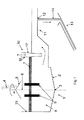
図1は本発明による方法が、溶融(fusion)から繊維成形までの連続モードで動作することを可能にするエレメントを示している。傾斜面を有する炉の底部2と、円筒型の側壁15とを有する円形炉1には、垂直軸6を中心に回転する金属円錐5へ落とされるガラス化可能材料4が供給される。この回転により、ガラス化可能材料を中心軸6を中心とする大きな表面積にわたって分配することができる。傾斜面は円錐の一部であり、その頂点3は下方向に向き、上方向に向くとすかし角を形成する。まだ溶融していないガラス化可能材料は、溶融する前及び溶融している材料のバス8に供給する前に、表面上にクラスト7を形成する。電極9はガラス化可能材料の溶融(fusion)に必要なカロリーを発生する。溶融している材料は、調節可能な高さのダム10下を通過することにより炉1を出て、水の循環により冷やされる。これらは、引き続きオリフィス12を有する分配チャンネル11に到着する(1つのオリフィスのみ示し、他のオリフィスはさらにチャンネルの右側に沿って存在することができる)。これらはオリフィス12を通って流れてスレッド14を形成し、トラフ13へ落とされて図示していない繊維成形装置へ供給される。ダム10は台形の断面(図面の平面に対して不等辺四角形であり、図面は平面で示されている)を有し、換言すると、その最大の面16と17は底部方向に向かって接近している。
FIG. 1 shows an element that enables the method according to the invention to operate in a continuous mode from fusion to fiber shaping. A circular furnace 1 having a
図2は本発明による方法が、溶融(fusion)から繊維成形までの連続モードで動作することを可能にするエレメントを示している。炉の底部2がこの図では傾斜面の形態を取ることを除いて、図1と同じエレメントが全てみられる。この炉の底部2と円筒形壁15との交差は最も低い点23を有する湾曲した交差点を形成する。炉の底部と側壁の合致点は、この最も低い点において、溶融しているガラス化可能材料を受けることができる上方向に凹型である角度を形成する。バイパス系20により、原料は導管21方向に向けられて円錐5を中心としてその上方に分配されるか、或いは導管22方向に向けられてこれらのガラス化可能材料を炉の底部2の最も低い点23の近くに分配することが可能である。導管22による分配は、可能な限り迅速に角23に最大量の溶融している材料を蓄積する方法で、炉の充填の開始時に行われる。このプロセスの開始時に少量の溶融している材料が蓄積すると、炉のプライム(起動)が可能である。原料が炉の底部の最も低い点23を通る垂線の近くに導管22を経て流されるとき、電極9も最低の点23を通る垂線の近くに位置されるように水平に移動される。必要な場合、排出プラグ24が炉を空にすることを可能にする。
FIG. 2 shows the elements that enable the method according to the invention to operate in a continuous mode from fusion to fiber shaping. All the same elements as in FIG. 1 can be seen except that the
図3は、図2の炉における原料と電極との分布について装置の相対位置を上面図で示している。炉の円筒形壁15と分配チャンネル11を見ることができる。充填開始時(図3のa)に、原料を最も低い点23(図2参照)の上で、可能な限り近い導管22を介して導入する。電極9をこの最も低い点23の上方に可能な限り近く位置させる。連続的な生産プロセス(図3のb)では、原料を炉の中心の導管21を介して導入する。電極9は炉の中心を包囲するように動かされている。
FIG. 3 is a top view showing the relative position of the apparatus with respect to the distribution of raw materials and electrodes in the furnace of FIG. The
例
酸化物タイプの粉末にされた原料を、ガラス装填を形成するように図1に示されているタイプの炉へ導入する。
EXAMPLE Oxide-type powdered raw material is introduced into a furnace of the type shown in FIG. 1 to form a glass charge.
シリカ:43%
アルミナ:21%
酸化鉄:6%
CaO+MgO:17%
Na2O+K2O:11%
TiO2:0.7%
630キロワットの粉末を電極を経て供給する。ダムの高さは変化され、温度は連続モードにおいて種々の高さで、及び一日当たり10トンの一定出力で測定された。以下の表1は炉の底部とダムの最も低い点との間の種々の距離についての結果を提示している。

Alumina: 21%
Iron oxide: 6%
CaO + MgO: 17%
Na 2 O + K 2 O: 11%
TiO 2 : 0.7%
630 kilowatts of powder is fed through the electrodes. The height of the dam was varied and the temperature was measured at various heights in continuous mode and at a constant power of 10 tons per day. Table 1 below presents the results for various distances between the bottom of the furnace and the lowest point of the dam.
Claims (14)
Applications Claiming Priority (3)
| Application Number | Priority Date | Filing Date | Title |
|---|---|---|---|
| FR1162500A FR2985254B1 (en) | 2011-12-28 | 2011-12-28 | METHOD FOR FIBRING VITREOUS MATERIALS |
| FR1162500 | 2011-12-28 | ||
| PCT/FR2012/052978 WO2013098504A1 (en) | 2011-12-28 | 2012-12-18 | Method for drawing vitrifiable materials |
Publications (3)
| Publication Number | Publication Date |
|---|---|
| JP2015504839A JP2015504839A (en) | 2015-02-16 |
| JP2015504839A5 JP2015504839A5 (en) | 2016-02-04 |
| JP6138823B2 true JP6138823B2 (en) | 2017-05-31 |
Family
ID=47628308
Family Applications (1)
| Application Number | Title | Priority Date | Filing Date |
|---|---|---|---|
| JP2014549516A Active JP6138823B2 (en) | 2011-12-28 | 2012-12-18 | Method for forming fibers from vitrifiable materials |
Country Status (15)
| Country | Link |
|---|---|
| US (1) | US20140366584A1 (en) |
| EP (1) | EP2797846B1 (en) |
| JP (1) | JP6138823B2 (en) |
| KR (1) | KR102017037B1 (en) |
| CN (1) | CN104010978B (en) |
| AU (1) | AU2012360254B2 (en) |
| BR (1) | BR112014016125B1 (en) |
| CA (1) | CA2861615C (en) |
| CL (1) | CL2014001750A1 (en) |
| CO (1) | CO7020902A2 (en) |
| DK (1) | DK2797846T3 (en) |
| ES (1) | ES2636774T3 (en) |
| FR (1) | FR2985254B1 (en) |
| PL (1) | PL2797846T3 (en) |
| WO (1) | WO2013098504A1 (en) |
Families Citing this family (4)
| Publication number | Priority date | Publication date | Assignee | Title |
|---|---|---|---|---|
| FR3023550B1 (en) * | 2014-07-08 | 2016-07-29 | Saint Gobain Isover | GLASS FUSION DEVICE COMPRISING AN OVEN, CHANNEL AND DAM |
| FR3030487B1 (en) * | 2014-12-19 | 2019-06-07 | Saint-Gobain Isover | ELECTRIC MOBILE ELECTRIC OVEN |
| EP3967665B1 (en) * | 2019-05-08 | 2024-07-17 | AGC Inc. | Method for producing melt, method for producing glass article, dissolution device, and device for producing glass article |
| FR3132094A1 (en) | 2022-01-25 | 2023-07-28 | Saint-Gobain Isover | Electric glass furnace, methods of melting and manufacturing glass using said furnace |
Family Cites Families (30)
| Publication number | Priority date | Publication date | Assignee | Title |
|---|---|---|---|---|
| FR553128A (en) * | 1921-07-27 | 1923-05-14 | Libbey Owens Sheet Glass Co | Stop barrier for molten glass |
| US2990438A (en) * | 1945-07-07 | 1961-06-27 | Saint Gobain | Methods of and tank furnaces for making glass |
| US2677003A (en) * | 1949-01-04 | 1954-04-27 | Saint Gobain | Glass furnace |
| FR1260542A (en) * | 1959-06-26 | 1961-05-05 | Tank furnace speed adjustment device | |
| US3208841A (en) * | 1960-10-06 | 1965-09-28 | Owens Illinois Glass Co | Apparatus for melting glass |
| US3399046A (en) * | 1964-12-29 | 1968-08-27 | Levi S. Longenecker | Furnace suspended skimmer wall |
| US3421876A (en) * | 1965-11-04 | 1969-01-14 | Anchor Hocking Glass Corp | Glass furnace with two separate throat passages |
| BE794781A (en) * | 1972-02-01 | 1973-07-31 | Ppg Industries Inc | HIGH MELTING POINT GLASS SHAPING PROCESS |
| GB1503145A (en) * | 1974-04-26 | 1978-03-08 | Pilkington Brothers Ltd | Glass melting |
| US3912488A (en) | 1974-07-25 | 1975-10-14 | Johns Manville | Electric furnace outlet |
| US3976464A (en) * | 1974-08-05 | 1976-08-24 | Owens-Corning Fiberglas Corporation | Skimmer |
| DE2911510A1 (en) * | 1978-12-08 | 1980-06-19 | Saint Gobain | Fiberising glass using orificed centrifugal spinner |
| US4349376A (en) * | 1981-06-08 | 1982-09-14 | Owens-Corning Fiberglas Corporation | Liquid cooled skimmer |
| KR860000995B1 (en) * | 1984-05-09 | 1986-07-26 | 주식회사 : 금강 | Preparing for method of inorganic fiber |
| DE3441442A1 (en) | 1984-11-13 | 1986-05-15 | Knauf-Research-Cottrell GmbH & Co Umwelttechnik KG, 8715 Iphofen | METHOD FOR IMPLEMENTING GAS WITH SUSPENSIONS |
| JPS63176313A (en) * | 1987-01-14 | 1988-07-20 | Sumitomo Metal Ind Ltd | Electric furnace for producing rock wool |
| GB8710298D0 (en) * | 1987-04-30 | 1987-06-03 | Glaverbel | Glass-melting furnace |
| FR2619560B1 (en) * | 1987-08-18 | 1992-10-30 | Saint Gobain Vitrage | PROCESS AND DEVICE FOR PRODUCING MOLTEN GLASS |
| FR2677973B1 (en) | 1991-06-20 | 1994-10-21 | Saint Gobain Isover | METHOD AND DEVICE FOR FORMING FIBERS. |
| FR2703041B1 (en) * | 1993-03-23 | 1995-06-09 | Saint Gobain Vitrage Int | PROCESS AND DEVICE FOR MELTING GLASS. |
| FR2711982B1 (en) * | 1993-11-02 | 1996-01-19 | Saint Gobain Vitrage | Transfer and conditioning channel for molten glass. |
| US6044667A (en) * | 1997-08-25 | 2000-04-04 | Guardian Fiberglass, Inc. | Glass melting apparatus and method |
| FR2778401A1 (en) | 1998-05-06 | 1999-11-12 | Saint Gobain Isover | COMPOSITION OF MINERAL WOOL |
| FR2778399A1 (en) | 1998-05-06 | 1999-11-12 | Saint Gobain Isover | COMPOSITION OF MINERAL WOOL |
| FR2779713B1 (en) | 1998-06-12 | 2000-07-21 | Saint Gobain Isover | DEVICE AND METHOD FOR CENTRIFUGING MINERAL FIBERS |
| FR2783516B1 (en) * | 1998-09-17 | 2000-11-10 | Saint Gobain Isover | COMPOSITION OF MINERAL WOOL |
| DE10041757C1 (en) * | 2000-08-25 | 2002-02-21 | Schott Glas | Method and device for refining glass |
| JP2003292323A (en) * | 2002-04-01 | 2003-10-15 | Nippon Electric Glass Co Ltd | Glass-fusing furnace and glass-fusing method |
| US7638447B2 (en) * | 2003-10-06 | 2009-12-29 | Saint-Gobain Isover | Mineral wool composition |
| FR2883864B1 (en) | 2005-04-01 | 2007-06-15 | Saint Gobain Isover Sa | COMPOSITIONS FOR GLASS FIBERS |
-
2011
- 2011-12-28 FR FR1162500A patent/FR2985254B1/en not_active Expired - Fee Related
-
2012
- 2012-12-18 CA CA2861615A patent/CA2861615C/en active Active
- 2012-12-18 BR BR112014016125-9A patent/BR112014016125B1/en active IP Right Grant
- 2012-12-18 DK DK12819090.7T patent/DK2797846T3/en active
- 2012-12-18 PL PL12819090T patent/PL2797846T3/en unknown
- 2012-12-18 WO PCT/FR2012/052978 patent/WO2013098504A1/en active Application Filing
- 2012-12-18 KR KR1020147017687A patent/KR102017037B1/en active IP Right Grant
- 2012-12-18 JP JP2014549516A patent/JP6138823B2/en active Active
- 2012-12-18 CN CN201280065404.8A patent/CN104010978B/en active Active
- 2012-12-18 EP EP12819090.7A patent/EP2797846B1/en active Active
- 2012-12-18 US US14/368,984 patent/US20140366584A1/en not_active Abandoned
- 2012-12-18 AU AU2012360254A patent/AU2012360254B2/en active Active
- 2012-12-18 ES ES12819090.7T patent/ES2636774T3/en active Active
-
2014
- 2014-06-27 CL CL2014001750A patent/CL2014001750A1/en unknown
- 2014-07-21 CO CO14157659A patent/CO7020902A2/en unknown
Also Published As
| Publication number | Publication date |
|---|---|
| WO2013098504A1 (en) | 2013-07-04 |
| AU2012360254B2 (en) | 2016-03-17 |
| BR112014016125A8 (en) | 2017-07-04 |
| CA2861615A1 (en) | 2013-07-04 |
| CN104010978A (en) | 2014-08-27 |
| BR112014016125A2 (en) | 2017-06-13 |
| KR102017037B1 (en) | 2019-09-02 |
| EP2797846B1 (en) | 2017-05-10 |
| DK2797846T3 (en) | 2017-10-23 |
| AU2012360254A1 (en) | 2014-08-14 |
| CN104010978B (en) | 2017-11-21 |
| ES2636774T3 (en) | 2017-10-09 |
| PL2797846T3 (en) | 2017-10-31 |
| CL2014001750A1 (en) | 2014-11-14 |
| FR2985254B1 (en) | 2013-12-20 |
| CA2861615C (en) | 2020-01-28 |
| CO7020902A2 (en) | 2014-08-11 |
| BR112014016125B1 (en) | 2020-11-10 |
| NZ627176A (en) | 2015-07-31 |
| KR20140116389A (en) | 2014-10-02 |
| FR2985254A1 (en) | 2013-07-05 |
| EP2797846A1 (en) | 2014-11-05 |
| US20140366584A1 (en) | 2014-12-18 |
| JP2015504839A (en) | 2015-02-16 |
Similar Documents
| Publication | Publication Date | Title |
|---|---|---|
| RU2246454C2 (en) | Method and a device for melting and refining of glass mass | |
| US3717450A (en) | Furnace for manufacture of striationfree quartz tubing | |
| JP6138823B2 (en) | Method for forming fibers from vitrifiable materials | |
| KR101385531B1 (en) | Arc melting equipment and molten metal manufacturing method using arc melting equipment | |
| JP6677707B2 (en) | Apparatus for melting glass, including furnaces, channels and barriers | |
| CN103849697B (en) | Molten slag treatment device and method for direct production of mineral wool or microcrystal product by utilizing molten slag of blast furnace | |
| CN107848854A (en) | Processed by electrical induction and the basalt of melting | |
| JPS6369720A (en) | Method and equipment for electric heat fusion of glass | |
| CN102803160B (en) | Method For Feeding Raw Material, Raw-material Feeder, And Apparatus And Process For Producing Glass Plate | |
| JP2015504839A5 (en) | ||
| US4138238A (en) | Method and apparatus for producing molten glass | |
| US2686821A (en) | Apparatus for melting and fiberizing refractory materials | |
| RU2689944C1 (en) | Method and device for production of continuous mineral fiber | |
| NZ627176B2 (en) | Method for drawing vitrifiable materials | |
| US2123544A (en) | Method of melting and refining glass | |
| US8627685B2 (en) | Method for melting at least one powdered mineral material | |
| US5338329A (en) | Process and device for obtaining mineral fibers | |
| CN104098264B (en) | The releasing device and its linkage path produced for mineral wool | |
| US20240182346A1 (en) | Vertical melting furnace for igneous rock fiber manufacturing | |
| KR20240138076A (en) | Electric glass melting furnace, method for melting and manufacturing glass through said melting furnace | |
| JPS62855B2 (en) | ||
| RU118410U1 (en) | DEVICE FOR PRODUCING MELTS FROM MINERAL RAW MATERIALS | |
| JPS6125660B2 (en) |
Legal Events
| Date | Code | Title | Description |
|---|---|---|---|
| A521 | Request for written amendment filed |
Free format text: JAPANESE INTERMEDIATE CODE: A523 Effective date: 20151207 |
|
| A621 | Written request for application examination |
Free format text: JAPANESE INTERMEDIATE CODE: A621 Effective date: 20151207 |
|
| A977 | Report on retrieval |
Free format text: JAPANESE INTERMEDIATE CODE: A971007 Effective date: 20161027 |
|
| A131 | Notification of reasons for refusal |
Free format text: JAPANESE INTERMEDIATE CODE: A131 Effective date: 20161108 |
|
| A521 | Request for written amendment filed |
Free format text: JAPANESE INTERMEDIATE CODE: A523 Effective date: 20170207 |
|
| TRDD | Decision of grant or rejection written | ||
| A01 | Written decision to grant a patent or to grant a registration (utility model) |
Free format text: JAPANESE INTERMEDIATE CODE: A01 Effective date: 20170328 |
|
| A61 | First payment of annual fees (during grant procedure) |
Free format text: JAPANESE INTERMEDIATE CODE: A61 Effective date: 20170426 |
|
| R150 | Certificate of patent or registration of utility model |
Ref document number: 6138823 Country of ref document: JP Free format text: JAPANESE INTERMEDIATE CODE: R150 |
|
| R250 | Receipt of annual fees |
Free format text: JAPANESE INTERMEDIATE CODE: R250 |
|
| R250 | Receipt of annual fees |
Free format text: JAPANESE INTERMEDIATE CODE: R250 |
|
| R250 | Receipt of annual fees |
Free format text: JAPANESE INTERMEDIATE CODE: R250 |
|
| R250 | Receipt of annual fees |
Free format text: JAPANESE INTERMEDIATE CODE: R250 |
|
| R250 | Receipt of annual fees |
Free format text: JAPANESE INTERMEDIATE CODE: R250 |