JP6138024B2 - Contaminated water block area generation method and apparatus - Google Patents
Contaminated water block area generation method and apparatus Download PDFInfo
- Publication number
- JP6138024B2 JP6138024B2 JP2013230909A JP2013230909A JP6138024B2 JP 6138024 B2 JP6138024 B2 JP 6138024B2 JP 2013230909 A JP2013230909 A JP 2013230909A JP 2013230909 A JP2013230909 A JP 2013230909A JP 6138024 B2 JP6138024 B2 JP 6138024B2
- Authority
- JP
- Japan
- Prior art keywords
- contaminated water
- compressed air
- block area
- chamber
- pressurized air
- Prior art date
- Legal status (The legal status is an assumption and is not a legal conclusion. Google has not performed a legal analysis and makes no representation as to the accuracy of the status listed.)
- Active
Links
Images
Landscapes
- Processing Of Solid Wastes (AREA)
Description
本発明は、汚染水ブロックエリア生成方法及び装置に関するものであり、より詳細には、有害物質を含んだ地下汚染水を一定エリアに封じ込め、当該エリア外に流出することを防止するための汚染水ブロックエリア生成方法及び装置に関するものである。なお、本発明に係る方法及び装置は、主に既に汚染水が発生している個所に実施することを想定しているために、以下の説明においては地下水を汚染水と称しているが、汚染水の流出予防のために予め実施する場合における地下水は未汚染水ということになるが、以下の説明における汚染水はこの未汚染水をも含むものと理解されたい。 The present invention relates to a method and apparatus for generating a contaminated water block area, and more specifically, contaminated water for containing underground contaminated water containing harmful substances in a certain area and preventing it from flowing out of the area. The present invention relates to a block area generation method and apparatus. In addition, since it is assumed that the method and apparatus according to the present invention are mainly performed at a location where contaminated water has already been generated, groundwater is referred to as contaminated water in the following description. The groundwater in the case where it is carried out in advance for preventing the outflow of water is uncontaminated water, but it should be understood that the contaminated water in the following description includes this uncontaminated water.
福島原発事故による汚染水の流出を契機に、地下水汚染問題が種々取り沙汰されている。この地下水汚染は、原発事故に起因するものに限られる訳ではなく、例えば、農作業に際して使用される農薬や化学工場から排出される廃棄物が地中に浸潤する等によっても発生するもので、各所で頻発している。一般に地下構造は、地表側から順に、不飽和帯、帯水層(飽和帯)、難透水層となっており、有害物質は不飽和帯に浸潤し、不飽和帯中の土壌水に混ざり込み、土壌水の運動(毛管力、吸着力、浸透力等の釣り合いによる)に伴って土壌間隙を通って移動し、地下水中に流れ込む。 Various groundwater pollution problems have been addressed by the outflow of contaminated water caused by the Fukushima nuclear accident. This groundwater contamination is not limited to those caused by the nuclear accident. For example, agricultural chemicals used during farming and waste discharged from chemical factories infiltrate the ground. It is frequent. In general, the underground structure consists of an unsaturated zone, an aquifer (saturated zone), and a poorly permeable layer in order from the surface, and harmful substances infiltrate into the unsaturated zone and mix with the soil water in the unsaturated zone. It moves through the soil gap with the movement of soil water (due to the balance of capillary force, adsorption force, osmotic force, etc.) and flows into the groundwater.
そして、有害物質を含む地下水が川や池等に流れ込むと、そこにおいて地下水中の有害物質が凝集沈殿し、水底に堆積する。底質に多くの有害物質が蓄積されると底質汚染が引き起こされ、水底や底質に生息する生物が体内で有害物質を濃縮蓄積し、食物連鎖によって人がこれを食することにより、健康被害を招くことになる。 When groundwater containing harmful substances flows into rivers, ponds, etc., harmful substances in the groundwater agglomerate and settle there, and accumulate on the bottom of the water. Accumulation of toxic substances in the sediment causes sediment contamination, and organisms that inhabit the bottom of the water and sediment concentrate and accumulate toxic substances in the body. It will cause damage.
従来、地盤内に存在する汚染物質を分離除去するに先立ち、該汚染物質が周辺に拡散することを防止するための方法としては、該汚染物質の存在する地盤部分を止水壁で取り囲んで封じ込める方法が一般的である(特開2011−156453号公報、特開2003−33757号公報等)。 Conventionally, prior to separating and removing contaminants existing in the ground, as a method for preventing the contaminants from diffusing to the surrounding area, the ground portion where the contaminants exist is surrounded by a water blocking wall and contained. The method is general (JP 2011-156453 A, JP 2003-33757 A, etc.).
しかるに、その止水壁は人工壁であって、鋼矢板やSMW地中連続壁によって構築されるが、その下端が難透水層(不透水層)に達する深さまで構築する必要があるため、工事が大掛かりなものとなり、施工に多大な時間とコストがかかる。また、この方法は、あくまで地盤内に汚染物質が存在することが発覚した後の事後措置であり、汚染物質を排出するおそれがある施設に対して、予防的に設置するに適した方法ではない。 However, the water barrier is an artificial wall and is constructed with steel sheet piles and SMW underground continuous walls, but it must be constructed to the depth where the lower end reaches the impermeable layer (impermeable layer). Is a large-scale one and requires a lot of time and cost for construction. In addition, this method is a post-action measure after it is discovered that there is a pollutant in the ground, and is not a method suitable for preventive installation in facilities that may discharge the pollutant. .
上述したように、従来提唱されている、地盤内に存在する汚染物質の拡散防止方法は、鋼矢板やSMW地中連続壁によって、その下端が難透水層に達する深さまで構築する必要があるため、工事が大掛かりなものとなり、施工に多大な時間とコストがかかるという問題があり、また、汚染物質を排出するおそれがある施設に対して、予防的に設置するに適するものではなかった。 As described above, the conventionally proposed method for preventing the diffusion of pollutants in the ground needs to be constructed to a depth at which the lower end reaches the hardly permeable layer by a steel sheet pile or SMW underground continuous wall. However, the construction is large-scale, and there is a problem that the construction takes a lot of time and cost, and it is not suitable for preventive installation in a facility that may discharge pollutants.
本発明は、このような従来技術における問題に鑑みてなされたもので、従来のような人工の大掛かりな止水壁の構築を伴うことなく、簡易な手段で、有害物質を含んだ地下汚染水を一定エリアに封じ込めて当該エリア外に流出することを防止すると共に、当該エリア外から流入することを防止することができ、施工に従来のような時間とコストがかからず、現に地盤内に有害物質が存在する場合の拡散防止のみならず、有害物質を排出するおそれがある施設近辺に、予防的に設置するにも好適で、液状化防止対策ともなり得る汚染水ブロックエリア生成装置、及び、その装置を用いた汚染水ブロックエリア生成方法を提供することを課題とする。 The present invention has been made in view of such problems in the prior art, and does not involve the construction of a large artificial water blocking wall as in the prior art. Can be prevented from flowing out of the area by keeping it in a certain area, and it can be prevented from flowing out of the area. Contaminated water block area generation device that is suitable not only for prevention of diffusion when harmful substances are present, but also for preventive installation near facilities where there is a risk of discharging harmful substances, and can also be a measure to prevent liquefaction, and An object of the present invention is to provide a method for generating a contaminated water block area using the apparatus.
上記課題を解決するための請求項1に係る発明は、上面を蓋で閉塞した井戸の内部中間位置に仕切板を配設して前記仕切板の上側に汚染水流入室を形成すると共にその下側に加圧空気室を形成し、前記汚染水流入室に側方に抜ける汚染水流入孔を多数形成して、そこから周囲土壌内の地下汚染水が汚染水流入室内に自然流入するようにし、また、前記加圧空気室に側方に抜ける圧縮空気噴出孔を多数形成して、前記加圧空気室内に供給される圧縮空気が前記圧縮空気噴出孔及び前記井戸の底面開口部から周囲土壌内に送出されるようにし、前記蓋及び前記仕切板を貫通して前記加圧空気室内に臨む圧縮空気供給パイプを配備し、また、前記蓋を貫通して前記汚染水流入室内に臨む第1排水パイプを配備して成る汚染水ブロックエリア生成装置である。
In the invention according to
一実施形態においては、前記圧縮空気供給パイプは前記加圧空気室内下部にまで延ばし、更に、前記蓋及び前記仕切板を貫通して前記加圧空気室内に臨む第2排水パイプを配備し、また、前記第1排水パイプ及び前記第2排水パイプに揚水ポンプを設置する。 In one embodiment, the compressed air supply pipe extends to the lower part of the pressurized air chamber, and further includes a second drain pipe that penetrates the lid and the partition plate and faces the pressurized air chamber. A pump is installed in the first drain pipe and the second drain pipe.
一実施形態においては更に、前記蓋及び前記仕切板を貫通して前記加圧空気室内に臨み、前記加圧空気室内の調圧を行う第1調圧パイプを配備し、また、前記蓋を貫通して前記汚染水流入室内に臨み、前記汚染水流入室内の調圧を行う第2調圧パイプを配備する。また更に、前記井戸の汚染水流入孔形成部及び圧縮空気噴出孔形成部の周囲に、前記各孔の目詰まりを防止するための砂利層を設けることとする。 In one embodiment, a first pressure adjusting pipe that passes through the lid and the partition plate to face the pressurized air chamber and regulates the pressure in the pressurized air chamber is further provided, and penetrates the lid. Then, a second pressure regulating pipe that faces the contaminated water inflow chamber and regulates the pressure in the contaminated water inflow chamber is provided. Furthermore, a gravel layer for preventing clogging of each hole is provided around the contaminated water inflow hole forming portion and the compressed air ejection hole forming portion of the well.
また、上記課題を解決するための請求項8に係る発明は、請求項1乃至7のいずれかに記載の汚染水ブロックエリア生成装置を設置する工程と、前記井戸の上部周辺部の汚染水を前記汚染水流入孔から前記汚染水流入室内に自然流入させる工程と、前記汚染水流入室内に流入して溜まった汚染水を、前記第1排水パイプを介して排出する工程と、前記加圧空気室内に圧縮空気を供給し、供給された前記圧縮空気を前記圧縮空気噴出孔及び底面開口部から周辺土壌中に噴出する工程と、前記土壌中に噴出させた圧縮空気によって土壌中の砂土粒子を外方に移動させて土壌間隙を充填する工程と、前記土壌間隙の充填によって、前記井戸を囲むように有底のすり鉢状の止水壁を自然形成させる工程と、を含むことを特徴とする汚染水ブロックエリア生成方法である。
Further, an invention according to
一実施形態においては、前記加圧空気室内下部に溜まった汚染水を、前記第2排水パイプを介して排出する工程を含み、また更に、前記汚染水流入室内及び前記加圧空気室内の余剰空気を前記第1調圧パイプ及び前記第2調圧パイプを介して排出する工程を含む。 In one embodiment, the method includes a step of discharging the contaminated water accumulated in the lower portion of the pressurized air chamber through the second drain pipe, and further, excess air in the contaminated water inflow chamber and the pressurized air chamber. Is discharged through the first pressure regulating pipe and the second pressure regulating pipe.
また、上記課題を解決するための請求項11に係る発明は、地盤の帯水層中の汚染水を回収しつつ、その汚染水回収個所よりも下の個所において圧縮空気を水平方向及び下方向に供給して砂土粒子を放射状に移動させて土壌間隙を充填させていくことで、前記圧縮空気供給部を囲むようにすり鉢状の止水壁を生成することを特徴とする汚染水ブロックエリア生成方法である。 In the invention according to claim 11 for solving the above-mentioned problem, while collecting the polluted water in the ground aquifer, the compressed air is discharged in the horizontal direction and the downward direction at a location below the polluted water recovery location. A mortar-shaped water blocking wall is generated so as to surround the compressed air supply part by moving sand soil particles radially and filling the soil gap. It is a generation method.
本発明は上述したとおりであって、地盤中に供給する圧縮空気の作用で自然に有底すり鉢状の止水壁を構築させるものであるので、従来の方法に比較して施工が容易でコストがかからず、有害物質を含んだ地下汚染水を一定エリアに封じ込めてエリア外に流出すること、並びに、エリア外から流入することを確実に防止することができ、現に地盤内に有害物質が存在する場合の拡散防止のみならず、有害物質を排出するおそれがある施設近辺に、予防的に設置するのにも好適なる効果がある。 The present invention is as described above, and is constructed with a bottomed mortar-shaped water-stop wall by the action of compressed air supplied into the ground. Therefore, the construction is easier and less expensive than the conventional method. Therefore, it is possible to reliably prevent underground contaminated water containing hazardous substances from flowing out of the area and flowing out of the area, and to prevent harmful substances from entering the ground. In addition to preventing diffusion when present, it has an advantageous effect for preventive installation near facilities where there is a risk of discharging harmful substances.
また、止水壁が有底すり鉢状に生成されるため、井戸は、必ずしも従来の止水壁のように難透水層に達するまで掘設する必要はなく、また、当該エリア内における汚染水が排出されることにより、当該エリア内における液状化現象の発生が防止される効果がある。 In addition, since the water blocking wall is generated in the shape of a bottomed mortar, it is not always necessary to dig a well until it reaches the poorly permeable layer as in the case of a conventional water blocking wall. By discharging, there is an effect of preventing the occurrence of a liquefaction phenomenon in the area.
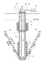
本発明を実施するための形態につき、添付図面を参照しつつ説明する。本発明に係る汚染水ブロックエリア生成方法は、地盤の帯水層中の汚染水を回収しつつ、その汚染水回収個所よりも下の個所において圧縮空気を水平方向及び下方向に供給して砂土粒子を放射状に移動させて土壌間隙を充填させていくことで、前記圧縮空気供給部を囲むようにすり鉢状の止水壁を生成することを特徴とするものであり、図1は、その方法を実施するための装置の概略構成及び作用を示す縦断面図である。 DESCRIPTION OF EMBODIMENTS Embodiments for carrying out the present invention will be described with reference to the accompanying drawings. The method for producing a contaminated water block area according to the present invention collects contaminated water in the ground aquifer and supplies compressed air in a horizontal direction and a downward direction at a location below the contaminated water recovery location. The mortar-shaped water blocking wall is generated so as to surround the compressed air supply unit by moving the soil particles radially to fill the soil gap, and FIG. It is a longitudinal cross-sectional view which shows schematic structure and an effect | action of the apparatus for enforcing a method.
図1に示されるように、本発明に係る汚染水ブロックエリア生成装置は、上面が蓋2によって閉塞された井戸1によって構成される。井戸1は、後述する理由により、必ずしも、下端部が難透水層に達する深さにまで掘設する必要はない。井戸1の内部中間位置に仕切板3が配設されることにより、仕切板3の上側に汚染水流入室4が形成され、仕切板3の下側に加圧空気室5が形成される。汚染水流入室4には、その全周に亘って側方に抜ける汚染水流入孔6が多数形成され、そこから周囲土壌内の地下汚染水が汚染水流入室4内に自然流入するようにされる。
As shown in FIG. 1, the contaminated water block area generating apparatus according to the present invention includes a
また、加圧空気室5には、その全周に亘って側方に抜ける圧縮空気噴出孔7が多数形成され、後述するようにして加圧空気室5内に供給される圧縮空気が、そこを通って周囲土壌内に送出される。なお、図1においては、仕切板3は比較的上方位置に配置されているが、より下方、即ち、圧縮空気噴出孔7形成部よりも少し上側に配置すれば足りる。 The compressed air chamber 5 is formed with a number of compressed air ejection holes 7 that escape laterally over the entire circumference, and compressed air supplied into the pressurized air chamber 5 as described later is provided there. Through and into the surrounding soil. In FIG. 1, the partition plate 3 is disposed at a relatively upper position, but it is sufficient that the partition plate 3 is disposed at a lower position, that is, slightly above the compressed air ejection hole 7 forming portion.
好ましい実施形態においては、汚染水流入孔6及び圧縮空気噴出孔7形成部の周囲に、各孔の目詰まりを防止するための砂利層8が設けられる。また、砂利層8は、井戸1の底面開口部9付近にも設けることが好ましい。
In a preferred embodiment, a
蓋2及び仕切板3を貫通させて、加圧空気室5内に臨む圧縮空気供給パイプ11が配設され、その外端部にコンプレッサー10が接続される。圧縮空気供給パイプ11は加圧空気室5内に圧縮空気を供給するためのものであるが、後述するように、本発明に係る方法においては、上部よりも土壌圧の高い井戸の下部周辺に圧縮空気を送出することが望まれるので、圧縮空気供給パイプ11は、なるべく加圧空気室5内下部にまで延ばして開口させることが好ましい。
A compressed air supply pipe 11 that penetrates the lid 2 and the partition plate 3 and faces the pressurized air chamber 5 is disposed, and a
また、蓋2を貫通させて、汚染水流入室4内に臨む第1排水パイプ12が配備される。第1排水パイプ12は、汚染水流入室4内に溜まった汚染水を排出するためのものであるので、汚染水流入室4の内底面近くにまで延ばされる。また更に、蓋2及び仕切板3を貫通させて、加圧空気室5内に臨む第2排水パイプ13が配備される。この第2排水パイプ13は、加圧空気室5内に溜まった汚染水を排出するためのものであるが、汚染水の水面が圧縮空気噴出孔7形成部に達する前に排出する必要があるので、その下端開口部は加圧空気室5内の下端部付近にまで延ばされる。通例、第1排水パイプ12及び第2排水パイプ13には、揚水ポンプが接続される。
Moreover, the
好ましい実施形態においては更に、蓋2を貫通して汚染水流入室4内に臨む第1調圧パイプ14と、蓋2及び仕切板3を貫通して加圧空気室5内に臨む第2調圧パイプ15とが配設される。第1調圧パイプ14は、汚染水流入室4内上部に溜まったガスを排出するためのものであるので、その下端開口部が汚染水流入室4の上部に開口するように配置される。また、第2調圧パイプ15は、加圧空気室5内の空気圧調整を行うためのものであるので、その下端開口部が加圧空気室5内の上部に開口するように配置される。通例、各調圧パイプ14、15には、気圧計付きバルブが設置され、所定圧以上になったときに当該バルブを開いて排気するように構成される。
In a preferred embodiment, the first
本発明に係る汚染水ブロックエリア生成方法は、上記汚染水ブロックエリア生成装置を用いて実施するもので、以下の工程から成る。 The contaminated water block area generating method according to the present invention is carried out using the contaminated water block area generating apparatus, and includes the following steps.
井戸掘設工程
この工程は、上記構成の汚染水ブロックエリア生成装置における井戸1を掘設する工程である。井戸1の下端部は、必ずしも難透水層に達するまで延ばす必要はない。それは、後述するように、止水壁16は井戸1の下方にも自然形成されるからである。井戸1は、例えば、原子炉、化学工場、薬品工場等の有害物質を排出する可能性のある施設の付近に設け、あるいは、当該施設を囲むように複数配設する。井戸1の掘設に際しては、汚染水流入孔6が不飽和帯の下の帯水層に位置するようにする。そして好ましくは、汚染水流入孔6及び圧縮空気噴出孔7形成部の周囲、並びに、底面開口部9付近に、各孔の目詰まりを防止するための砂利層8を設ける。
Well digging process This process is a process of digging the
汚染水回収工程
上記井戸1の掘設に伴って汚染水が、井戸1の全周面に亘って多数形成されている汚染水流入孔6から汚染水流入室4内に自然流入し、そこを満たしていく。汚染水流入室4内に溜まった汚染水は、適量を残し、揚水ポンプを用いて第1排水パイプから適時汲み出され、処理施設に搬送される。また、汚染水の流入に伴い、汚染水流入室4内の空気は、第1調圧パイプ14から放出される。
Contaminated water recovery process Contaminated water naturally flows into the contaminated
圧縮空気供給工程
井戸1を掘設した後、コンプレッサー10を始動して、加圧空気室5内に圧縮空気を供給する。供給された圧縮空気は、井戸1の全周面に配設されている圧縮空気噴出孔7から放射状に噴出し、また、底面開口部9から下方に噴出して周辺土壌中に送出され、土壌中の砂土粒子を外方に押しやるよう作用する。外方に押しやられた砂土粒子は土壌間隙を抜けて移動する。なお、加圧空気室5内への圧縮空気の供給に伴い、仕切壁3に下方から大きな負荷がかかるが、この負荷に対抗するために、汚染水流入室4内にある程度の量の汚染水を溜めておくことが好ましい。
Compressed air supply process After the
止水壁生成工程
そして、この圧縮空気の噴出を継続することにより、多くの砂土粒子が移動して溜まる井戸1から遠位の土壌間隙から次第に充填されて締め固められ、水密の壁が生成されていく。この壁は、内側の土壌水の流出並びに壁の外側の土壌水の流入を阻止し得る止水壁16となるもので、すり鉢状に形成されていく。即ち、井戸1の周囲の土壌の土壌圧力は、深くなればなるほど高く、浅くなればなるほど低くなる。従って、井戸1の深い位置から水平方向及び下方向に噴出する圧縮空気は、より圧力の低い上方向へと向かい、その方向に砂土粒子を移動させて土壌間隙を充填していく。その結果、止水壁16は有底のすり鉢状に形成されることになるのである。
Water stop wall generation process And by continuing this jet of compressed air, many sandy soil particles move and accumulate from the
このようにして汚染水ブロックエリアが形成されるが、例えば、井戸1の深さを100mとし、止水壁16の傾斜が45度であるとすると、形成される汚染水ブロックエリアの範囲は、井戸1を中心に半径100mということになり、仮にこの範囲内にある施設から有害物質が排出して地中に浸潤したとしても、止水壁16によってブロックされるため、外部に流出するおそれはない。
In this way, the contaminated water block area is formed. For example, if the depth of the
このように本発明に係る方法及び装置によれば、地盤中に供給する圧縮空気の作用で有底すり鉢状の止水壁16が自然生成されるので、従来の方法に比較して施工が容易で低コストでの実施が可能である。また、その止水壁16によって壁内外の汚染水がブロックされるため、有害物質を含んだ地下汚染水を一定エリアに封じ込めてエリア外に流出すること、並びに、エリア外から流入することを確実に防止することができる。
As described above, according to the method and apparatus of the present invention, the bottomed mortar-shaped
本発明に係る方法及び装置は、現に地盤内に有害物質が存在する場合の拡散防止のみならず、有害物質を排出するおそれがある施設近辺に、予防的に実施(設置)するのにも好適ということができる。また、止水壁16は有底すり鉢状に生成されるため、井戸は、必ずしも従来の止水壁のように難透水層に達するまで掘設する必要はなく、更に、当該エリア内における汚染水を排出するため、当該エリア内における液状化現象の発生を防止し得るものでもある。
The method and apparatus according to the present invention are suitable not only for prevention of diffusion when harmful substances are actually present in the ground, but also for preventive implementation (installation) in the vicinity of facilities where hazardous substances may be discharged. It can be said. Further, since the
1 井戸
2 蓋
3 仕切板
4 汚染水流入室
5 加圧空気室
6 汚染水流入孔
7 圧縮空気噴出孔
8 砂利層
9 底面開口部
10 コンプレッサー
11 圧縮空気供給パイプ
12 第1排水パイプ
13 第2排水パイプ
14 第1調圧パイプ
15 第2調圧パイプ
16 止水壁
DESCRIPTION OF
Claims (11)
前記井戸の上部周辺部の汚染水を前記汚染水流入孔から前記汚染水流入室内に自然流入させる工程と、
前記汚染水流入室内に流入して溜まった汚染水を、前記第1排水パイプを介して排出する工程と、
前記加圧空気室内に圧縮空気を供給し、供給された前記圧縮空気を前記圧縮空気噴出孔及び前記井戸の底面開口部から周辺土壌中に噴出する工程と、
前記土壌中に噴出させた圧縮空気によって土壌中の砂土粒子を外方に移動させて土壌間隙を充填する工程と、
前記土壌間隙の充填によって、前記井戸を囲むように有底のすり鉢状の止水壁を自然形成させる工程と、
を含むことを特徴とする汚染水ブロックエリア生成方法。 Installing the contaminated water block area generating device according to any one of claims 1 to 7,
Allowing the contaminated water in the upper periphery of the well to naturally flow into the contaminated water inflow chamber from the contaminated water inflow hole;
Discharging contaminated water flowing into the contaminated water inflow chamber through the first drain pipe;
Supplying compressed air into the pressurized air chamber, and ejecting the supplied compressed air from the compressed air ejection hole and the bottom opening of the well into the surrounding soil;
Filling the soil gap by moving sand particles in the soil outward by the compressed air jetted into the soil;
The step of naturally forming a bottomed mortar-shaped water blocking wall so as to surround the well by filling the soil gap;
Contaminated water block area generation method characterized by including.
Priority Applications (1)
| Application Number | Priority Date | Filing Date | Title |
|---|---|---|---|
| JP2013230909A JP6138024B2 (en) | 2013-11-07 | 2013-11-07 | Contaminated water block area generation method and apparatus |
Applications Claiming Priority (1)
| Application Number | Priority Date | Filing Date | Title |
|---|---|---|---|
| JP2013230909A JP6138024B2 (en) | 2013-11-07 | 2013-11-07 | Contaminated water block area generation method and apparatus |
Publications (2)
| Publication Number | Publication Date |
|---|---|
| JP2015089543A JP2015089543A (en) | 2015-05-11 |
| JP6138024B2 true JP6138024B2 (en) | 2017-05-31 |
Family
ID=53193327
Family Applications (1)
| Application Number | Title | Priority Date | Filing Date |
|---|---|---|---|
| JP2013230909A Active JP6138024B2 (en) | 2013-11-07 | 2013-11-07 | Contaminated water block area generation method and apparatus |
Country Status (1)
| Country | Link |
|---|---|
| JP (1) | JP6138024B2 (en) |
Families Citing this family (2)
| Publication number | Priority date | Publication date | Assignee | Title |
|---|---|---|---|---|
| JP6545523B2 (en) * | 2015-05-12 | 2019-07-17 | 大成建設株式会社 | Diffusion prevention wall and its construction method |
| CN115735444A (en) * | 2022-11-22 | 2023-03-07 | 四川农业大学 | Soil ecological restoration method based on limestone mining area and soil water retention device |
Family Cites Families (8)
| Publication number | Priority date | Publication date | Assignee | Title |
|---|---|---|---|---|
| US5445474A (en) * | 1994-01-27 | 1995-08-29 | Union Oil Company Of California | Pulsing remediation method |
| US5855775A (en) * | 1995-05-05 | 1999-01-05 | Kerfoot; William B. | Microporous diffusion apparatus |
| JP3467266B1 (en) * | 2002-09-17 | 2003-11-17 | 俊多 白石 | Prevention of ground liquefaction due to earthquake and facilities used for this method |
| JP3728510B2 (en) * | 2003-03-20 | 2005-12-21 | 武 長谷川 | Soil pollution countermeasure method and soil pollution countermeasure system |
| JP5142348B2 (en) * | 2006-03-13 | 2013-02-13 | 有限会社アサヒテクノ | How to prevent ground liquefaction |
| JP2007245052A (en) * | 2006-03-17 | 2007-09-27 | Nippon Oil Corp | In-situ oil recovery method for oil-contaminated soil |
| JP5341406B2 (en) * | 2008-06-20 | 2013-11-13 | 株式会社竹中工務店 | Purification well and purification method for contaminated soil. |
| JP2010188220A (en) * | 2009-02-16 | 2010-09-02 | Kajima Road Co Ltd | Contaminated soil cleaning method |
-
2013
- 2013-11-07 JP JP2013230909A patent/JP6138024B2/en active Active
Also Published As
| Publication number | Publication date |
|---|---|
| JP2015089543A (en) | 2015-05-11 |
Similar Documents
| Publication | Publication Date | Title |
|---|---|---|
| US10556260B2 (en) | Environmental remediation systems, devices, and methods | |
| JP5724222B2 (en) | Pumping unit, soft soil improvement method, ground excavation method, contaminated soil purification method, and condensate method | |
| CN103987898B (en) | Fluid containment administrating system | |
| RU2567927C2 (en) | Underground water control system for mine tunnels | |
| JP5659566B2 (en) | Pumping equipment, soft ground improvement method, ground excavation method, contaminated soil purification method, and condensate method | |
| US9649675B2 (en) | In-situ capping with no loss of water depth | |
| JP4997009B2 (en) | Rainwater penetration | |
| JP6138024B2 (en) | Contaminated water block area generation method and apparatus | |
| KR101720098B1 (en) | Apparatus for remediating polluted ground water by VOCs | |
| JP6870969B2 (en) | How to extubate an existing well | |
| JPH0762695A (en) | Stratified pumping equipment and well equipped with this | |
| JP3508997B2 (en) | How to clean contaminated soil | |
| CN104912126B (en) | Polluted-soil restoration system applicable to soft-soil foundation and restoration method | |
| KR100914682B1 (en) | Organic Wastewater Circulation Landfill with Vertical Wells and Ponds | |
| JP5695495B2 (en) | Overlay structure | |
| JP4657008B2 (en) | Contaminated ground purification system and purification method of contaminated ground | |
| CN111807492A (en) | NAPL pollution remediation system and method in underground water based on pollution prevention and control | |
| WO2013084303A1 (en) | Facility for transporting underwater sedimentation by suction and method for capturing foreign matter | |
| JP5070694B2 (en) | Containment method for contaminated soil and groundwater | |
| JP2013126639A (en) | Waste disposal facility | |
| JP5142348B2 (en) | How to prevent ground liquefaction | |
| JP5920561B2 (en) | Pollutant diffusion prevention structure and method | |
| RU2536496C1 (en) | Method of creation of curtain grouting with filter windows and beam water intake | |
| JP5839560B2 (en) | Waste disposal facility | |
| CN209940624U (en) | Circulating well |
Legal Events
| Date | Code | Title | Description |
|---|---|---|---|
| A621 | Written request for application examination |
Free format text: JAPANESE INTERMEDIATE CODE: A621 Effective date: 20160610 |
|
| A871 | Explanation of circumstances concerning accelerated examination |
Free format text: JAPANESE INTERMEDIATE CODE: A871 Effective date: 20160908 |
|
| A977 | Report on retrieval |
Free format text: JAPANESE INTERMEDIATE CODE: A971007 Effective date: 20161214 |
|
| A975 | Report on accelerated examination |
Free format text: JAPANESE INTERMEDIATE CODE: A971005 Effective date: 20161212 |
|
| A131 | Notification of reasons for refusal |
Free format text: JAPANESE INTERMEDIATE CODE: A131 Effective date: 20161219 |
|
| TRDD | Decision of grant or rejection written | ||
| A01 | Written decision to grant a patent or to grant a registration (utility model) |
Free format text: JAPANESE INTERMEDIATE CODE: A01 Effective date: 20170425 |
|
| A61 | First payment of annual fees (during grant procedure) |
Free format text: JAPANESE INTERMEDIATE CODE: A61 Effective date: 20170425 |
|
| R150 | Certificate of patent or registration of utility model |
Ref document number: 6138024 Country of ref document: JP Free format text: JAPANESE INTERMEDIATE CODE: R150 |
|
| R250 | Receipt of annual fees |
Free format text: JAPANESE INTERMEDIATE CODE: R250 |
|
| R250 | Receipt of annual fees |
Free format text: JAPANESE INTERMEDIATE CODE: R250 |
|
| R250 | Receipt of annual fees |
Free format text: JAPANESE INTERMEDIATE CODE: R250 |
|
| S111 | Request for change of ownership or part of ownership |
Free format text: JAPANESE INTERMEDIATE CODE: R313113 |
|
| R350 | Written notification of registration of transfer |
Free format text: JAPANESE INTERMEDIATE CODE: R350 |
|
| R250 | Receipt of annual fees |
Free format text: JAPANESE INTERMEDIATE CODE: R250 |
|
| R250 | Receipt of annual fees |
Free format text: JAPANESE INTERMEDIATE CODE: R250 |
|
| R250 | Receipt of annual fees |
Free format text: JAPANESE INTERMEDIATE CODE: R250 |