JP6136663B2 - Solid-state imaging device, manufacturing method thereof, and electronic device - Google Patents
Solid-state imaging device, manufacturing method thereof, and electronic device Download PDFInfo
- Publication number
- JP6136663B2 JP6136663B2 JP2013140398A JP2013140398A JP6136663B2 JP 6136663 B2 JP6136663 B2 JP 6136663B2 JP 2013140398 A JP2013140398 A JP 2013140398A JP 2013140398 A JP2013140398 A JP 2013140398A JP 6136663 B2 JP6136663 B2 JP 6136663B2
- Authority
- JP
- Japan
- Prior art keywords
- photoelectric conversion
- imaging device
- solid
- film
- conversion unit
- Prior art date
- Legal status (The legal status is an assumption and is not a legal conclusion. Google has not performed a legal analysis and makes no representation as to the accuracy of the status listed.)
- Active
Links
Images
Classifications
-
- H—ELECTRICITY
- H10—SEMICONDUCTOR DEVICES; ELECTRIC SOLID-STATE DEVICES NOT OTHERWISE PROVIDED FOR
- H10K—ORGANIC ELECTRIC SOLID-STATE DEVICES
- H10K39/00—Integrated devices, or assemblies of multiple devices, comprising at least one organic radiation-sensitive element covered by group H10K30/00
- H10K39/30—Devices controlled by radiation
- H10K39/32—Organic image sensors
-
- H—ELECTRICITY
- H10—SEMICONDUCTOR DEVICES; ELECTRIC SOLID-STATE DEVICES NOT OTHERWISE PROVIDED FOR
- H10K—ORGANIC ELECTRIC SOLID-STATE DEVICES
- H10K30/00—Organic devices sensitive to infrared radiation, light, electromagnetic radiation of shorter wavelength or corpuscular radiation
- H10K30/50—Photovoltaic [PV] devices
- H10K30/57—Photovoltaic [PV] devices comprising multiple junctions, e.g. tandem PV cells
-
- H—ELECTRICITY
- H10—SEMICONDUCTOR DEVICES; ELECTRIC SOLID-STATE DEVICES NOT OTHERWISE PROVIDED FOR
- H10K—ORGANIC ELECTRIC SOLID-STATE DEVICES
- H10K30/00—Organic devices sensitive to infrared radiation, light, electromagnetic radiation of shorter wavelength or corpuscular radiation
- H10K30/80—Constructional details
- H10K30/88—Passivation; Containers; Encapsulations
-
- Y—GENERAL TAGGING OF NEW TECHNOLOGICAL DEVELOPMENTS; GENERAL TAGGING OF CROSS-SECTIONAL TECHNOLOGIES SPANNING OVER SEVERAL SECTIONS OF THE IPC; TECHNICAL SUBJECTS COVERED BY FORMER USPC CROSS-REFERENCE ART COLLECTIONS [XRACs] AND DIGESTS
- Y02—TECHNOLOGIES OR APPLICATIONS FOR MITIGATION OR ADAPTATION AGAINST CLIMATE CHANGE
- Y02E—REDUCTION OF GREENHOUSE GAS [GHG] EMISSIONS, RELATED TO ENERGY GENERATION, TRANSMISSION OR DISTRIBUTION
- Y02E10/00—Energy generation through renewable energy sources
- Y02E10/50—Photovoltaic [PV] energy
- Y02E10/549—Organic PV cells
-
- Y—GENERAL TAGGING OF NEW TECHNOLOGICAL DEVELOPMENTS; GENERAL TAGGING OF CROSS-SECTIONAL TECHNOLOGIES SPANNING OVER SEVERAL SECTIONS OF THE IPC; TECHNICAL SUBJECTS COVERED BY FORMER USPC CROSS-REFERENCE ART COLLECTIONS [XRACs] AND DIGESTS
- Y02—TECHNOLOGIES OR APPLICATIONS FOR MITIGATION OR ADAPTATION AGAINST CLIMATE CHANGE
- Y02P—CLIMATE CHANGE MITIGATION TECHNOLOGIES IN THE PRODUCTION OR PROCESSING OF GOODS
- Y02P70/00—Climate change mitigation technologies in the production process for final industrial or consumer products
- Y02P70/50—Manufacturing or production processes characterised by the final manufactured product
Landscapes
- Physics & Mathematics (AREA)
- Electromagnetism (AREA)
- Solid State Image Pick-Up Elements (AREA)
- Engineering & Computer Science (AREA)
- Power Engineering (AREA)
- Microelectronics & Electronic Packaging (AREA)
- General Physics & Mathematics (AREA)
- Condensed Matter Physics & Semiconductors (AREA)
- Computer Hardware Design (AREA)
- Transforming Light Signals Into Electric Signals (AREA)
- Plasma & Fusion (AREA)
- Manufacturing & Machinery (AREA)
- Light Receiving Elements (AREA)
Description
本技術は、互いに異なる波長の光を吸収する複数の光電変換部を有する固体撮像素子およびその製造方法、並びに固体撮像素子を有する電子機器に関する。 The present technology relates to a solid-state imaging device having a plurality of photoelectric conversion units that absorb light having different wavelengths, a method for manufacturing the same, and an electronic apparatus having the solid-state imaging device.
CCD(Charge Coupled Device)イメージセンサおよびCMOS(Complementary Metal Oxide Semiconductor)イメージセンサ等の固体撮像装置では、画素サイズを縮小するにつれて単位画素(固体撮像素子)に入射するフォトン数が減少し、S/N比が低下する。画素は、例えばベイヤー配列等に代表されるように、カラーフィルタを用いて赤、緑および青の各色に分けられ、同一平面に配置される。この方法では、例えば緑、青の波長の光は赤の画素(カラーフィルタ)を透過できないため、光の損失が生じ、感度が低下する。また、赤、緑および青の画素間で補間処理を行って色信号を作るため、偽色が生じる虞がある。 In a solid-state imaging device such as a CCD (Charge Coupled Device) image sensor and a CMOS (Complementary Metal Oxide Semiconductor) image sensor, as the pixel size is reduced, the number of photons incident on a unit pixel (solid-state imaging device) is reduced. The ratio decreases. For example, as represented by a Bayer array, the pixels are divided into red, green, and blue colors using color filters and are arranged on the same plane. In this method, for example, light of green and blue wavelengths cannot be transmitted through a red pixel (color filter), so that light loss occurs and sensitivity decreases. In addition, since a color signal is generated by performing interpolation processing between red, green, and blue pixels, there is a possibility that a false color is generated.
そこで、3つの光電変換部を積層させて1つの画素で3色の光電変換信号を得る方法が提案されている。例えば、3つの光電変換部のうちの1つ(例えば緑色光に対応する光電変換部)はシリコン基板上、即ち、シリコン基板の外側に配置し、残りの2つ(例えば赤色光、青色光に対応する光電変換部)はシリコン基板の内部に設ける(例えば、特許文献1参照)。シリコン基板の外側の光電変換部は有機材料を含む光電変換層を有するものであり、この光電変換層が一対の電極の間に設けられている。一方、シリコン基板の内部の光電変換部はフォトダイオード(Photo Diode)により構成される。 Therefore, a method has been proposed in which three photoelectric conversion units are stacked to obtain a three-color photoelectric conversion signal with one pixel. For example, one of the three photoelectric conversion units (for example, the photoelectric conversion unit corresponding to green light) is arranged on the silicon substrate, that is, outside the silicon substrate, and the remaining two (for example, red light and blue light are used). A corresponding photoelectric conversion unit is provided inside the silicon substrate (see, for example, Patent Document 1). The photoelectric conversion portion outside the silicon substrate has a photoelectric conversion layer containing an organic material, and this photoelectric conversion layer is provided between a pair of electrodes. On the other hand, the photoelectric conversion unit inside the silicon substrate is configured by a photodiode.
また、3つの光電変換部がそれぞれ有機材料を含む光電変換層を有しており、これら3つの光電変換部を全て基板上に配置する方法も提案されている(例えば、特許文献2参照)。この撮像素子では、信号を読み出すためのTFT(Thin Film Transistor)がそれぞれの光電変換部に設けられている。 Also, a method has been proposed in which three photoelectric conversion units each have a photoelectric conversion layer containing an organic material, and all three photoelectric conversion units are arranged on a substrate (see, for example, Patent Document 2). In this image sensor, a TFT (Thin Film Transistor) for reading a signal is provided in each photoelectric conversion unit.
近年では、上記のような有機材料を含む光電変換部の大きさを精確に制御して、画素を微細化することが望まれている。 In recent years, it has been desired that the size of a photoelectric conversion unit including the organic material as described above is accurately controlled to reduce the size of a pixel.
本技術はかかる問題点に鑑みてなされたもので、その目的は、画素の微細化が可能な固体撮像素子およびその製造方法、並びにこの固体撮像素子を備えた電子機器を提供することにある。 The present technology has been made in view of such problems, and an object of the present technology is to provide a solid-state imaging device capable of miniaturizing pixels, a manufacturing method thereof, and an electronic device including the solid-state imaging device.
本技術による固体撮像素子は、1または2以上の第1光電変換部と、第1光電変換部に対向する位置に設けられ、有機層を含むと共に最初に光が入射する第2光電変換部と、有機層の光入射面を覆う紫外線防止膜とを備えたものである。 A solid-state imaging device according to the present technology includes one or more first photoelectric conversion units, a second photoelectric conversion unit that is provided at a position facing the first photoelectric conversion unit, includes an organic layer, and first receives light. And an ultraviolet ray preventing film covering the light incident surface of the organic layer.
本技術の固体撮像素子では、有機層の光入射面が紫外線防止膜により覆われている。このため、例えば、有機層を形成する際にプラズマ照射を行っても、これによって生じる紫外線が、有機層への到達前に遮られる。従って、ドライエッチングにより有機層をパターニングしても、紫外線による有機層の劣化が抑えられる。 In the solid-state imaging device of the present technology, the light incident surface of the organic layer is covered with an ultraviolet ray preventing film. For this reason, for example, even if plasma irradiation is performed when forming the organic layer, ultraviolet rays generated thereby are blocked before reaching the organic layer. Therefore, even if the organic layer is patterned by dry etching, deterioration of the organic layer due to ultraviolet rays can be suppressed.
本技術による電子機器は、上記本技術の固体撮像素子を有するものである。 An electronic apparatus according to the present technology includes the solid-state image sensor according to the present technology.
本技術による固体撮像素子の製造方法は、上記本技術の固体撮像素子の製造方法であり、1または2以上の第1光電変換部に対向する位置に、有機層を成膜することと、有機層の光入射面を紫外線防止膜で覆った後、有機層をパターニングして第2光電変換部を設けることとを含むものである。 A method for manufacturing a solid-state imaging device according to the present technology is a method for manufacturing the solid-state imaging device according to the present technology, in which an organic layer is formed at a position facing one or more first photoelectric conversion units, and organic Covering the light incident surface of the layer with an ultraviolet protection film and then patterning the organic layer to provide a second photoelectric conversion unit.
本技術の固体撮像素子およびその製造方法、並びに電子機器によれば、紫外線防止膜を設けるようにしたので、有機層をパターニングする際に、例えばドライエッチング等の微細加工可能な方法を用いることができる。よって、画素の微細化が可能となる。 According to the solid-state imaging device, the manufacturing method thereof, and the electronic device of the present technology, since the ultraviolet ray prevention film is provided, when patterning the organic layer, for example, a method capable of fine processing such as dry etching is used. it can. Therefore, the pixel can be miniaturized.
以下、本技術の実施の形態について、図面を参照して詳細に説明する。なお、説明
は以下の順序で行う。
1.第1の実施の形態(撮像素子:紫外線吸収膜が有機光電変換膜を覆う例)
2.変形例1(複数の有機光電変換部を有する例)
3.変形例2(下部電極側からホールを信号電荷として取り出す例)
4.変形例3(上部電極側から電子またはホールを信号電荷として取り出す例)
5.第2の実施の形態(撮像素子:紫外線反射膜が有機光電変換膜を覆う例)
6.適用例(撮像装置)
Hereinafter, embodiments of the present technology will be described in detail with reference to the drawings. The description will be given in the following order.
1. First embodiment (image sensor: an example in which an ultraviolet absorption film covers an organic photoelectric conversion film)
2. Modification 1 (example having a plurality of organic photoelectric conversion units)
3. Modification 2 (example in which holes are taken out as signal charges from the lower electrode side)
4). Modification 3 (example in which electrons or holes are taken out as signal charges from the upper electrode side)
5. Second embodiment (image sensor: an example in which an ultraviolet reflective film covers an organic photoelectric conversion film)
6). Application example (imaging device)
<第1実施の形態>
[撮像素子10の構成]
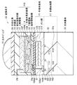
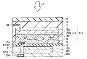
図1は、本技術の一実施の形態に係る固体撮像素子(撮像素子10)の断面構成を表したものである。撮像素子10は、例えばCCDイメージセンサまたはCMOSイメージセンサなどの撮像装置(例えば、後述の図18の撮像装置1)において1つの画素(例えば後述の図18の画素P)を構成するものである。この撮像素子10は所謂、裏面照射型の撮像素子であり、半導体基板11の受光面(面S1)とは反対側の面(面S2)に多層配線層51が設けられている。
<First embodiment>
[Configuration of Image Sensor 10]
FIG. 1 illustrates a cross-sectional configuration of a solid-state imaging device (imaging device 10) according to an embodiment of the present technology. The
撮像素子10は無機光電変換部11B,11R(第1光電変換部)と有機光電変換部11G(第2光電変換部)とを有しており、これらが互いに対向して縦方向(光路)に積み重ねられている。無機光電変換部11B,11Rは半導体基板11の内部に、有機光電変換部11Gは半導体基板11の面S1上にそれぞれ設けられている。即ち、撮像素子10では、無機光電変換部11B,11Rおよび有機光電変換部11Gのうち、有機光電変換部11Gに最初に光が入射するようになっている。有機光電変換部11Gは一対の電極(上部電極17および下部電極14)の間に有機光電変換層16(有機層)を有するものであり、上部電極17から有機光電変換層16に光が入射する。このような有機光電変換部11Gと無機光電変換部11B,11Rとでは、互いに異なる波長域の光を選択的に検出して光電変換を行うため、カラーフィルタを設けずに、1つの撮像素子10で複数種類の色信号を取得することができる。無機光電変換部11Rでは赤色(例えば、波長620nm〜750nm)、無機光電変換部11Bでは青色(例えば、波長450nm〜495nm)、有機光電変換部11Gでは緑色(例えば、波長495nm〜570nm)の色信号がそれぞれ取得されるようになっている。
The
半導体基板11の面S2近傍には例えばp型半導体ウェル領域(図示せず)が設けられている。この半導体基板11の面S2近傍には、有機光電変換部11G、無機光電変換部11B,11Rそれぞれに対応する複数の画素トランジスタ(後述の転送トランジスタTr1,Tr2,Tr3)も配置されている。転送トランジスタTr1,Tr2,Tr3は、それぞれゲート電極TG1,TG2,TG3を有している。転送トランジスタTr1は有機光電変換部11Gで発生した緑色に対応する信号電荷を、転送トランジスタTr2は無機光電変換部11Bで発生した青色に対応する信号電荷を、転送トランジスタTr3は無機光電変換部11Rで発生した赤色に対応する信号電荷をそれぞれ例えば垂直信号線Lsig(後述の図18)に転送するものである。信号電荷は、光電変換によって生じる電子およびホールのどちらであってもよいが、以下では、電子を信号電荷として読み出す場合(n型半導体領域を光電変換層とする場合)を例に挙げて説明する。
In the vicinity of the surface S2 of the
半導体基板11の面S2近傍には、上記転送トランジスタTr1,Tr2,Tr3と共に例えば、リセットトランジスタ、増幅トランジスタおよび選択トランジスタ等が設けられている。このようなトランジスタは例えばMOSEFT(Metal Oxide Semiconductor Field Effect Transistor)であり、光電変換部(有機光電変換部11G、無機光電変換部11B,11R)毎に回路を構成する。各回路は、例えば転送トランジスタ、リセットトランジスタおよび増幅トランジスタを含む3トランジスタ構成であってもよく、あるいはこれに選択トランジスタが加わった4トランジスタ構成であってもよい。転送トランジスタ以外のトランジスタは、光電変換部間または画素間で共有することも可能である。
In the vicinity of the surface S2 of the
半導体基板11は例えばn型のシリコン(Si)層により構成されており、その内部には上述の無機光電変換部11B,11Rと共に緑用蓄電層110Gが設けられている。
The
無機光電変換部11B,11Rは、pn接合を有するフォトダイオードであり、半導体基板11の面S1側から、例えば無機光電変換部11Bおよび無機光電変換部11Rの順に設けられている。
The inorganic
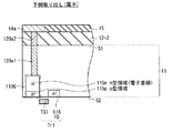
図2A,図2Bは無機光電変換部11B,11Rの詳細な構成を表したものである。無機光電変換部11Bは、ホール蓄積層となるp型半導体領域(以下、単にp型領域という、n型についても同様。)111pと電子蓄積層となるn型光電変換層(n型領域)111nとを含んで構成されている。図中、「p」「n」に上付きで記した「+(プラス)」は、p型またはn型の不純物濃度が高いことを表している。p型領域111pおよびn型光電変換層111nは、半導体基板11の面S1近傍の所定の領域に面S1の水平方向に設けられると共に、少なくともその一部は屈曲して面S1と垂直方向に延在している。半導体基板11の面S2近傍には青色用の転送トランジスタTr2のフローティングディフュージョン(FD113)が設けられ(図2B)、このn型領域のFD113にn型光電変換層111nが接続されている。p型領域111pおよびn型光電変換層111nと半導体基板11の面S2との間にはp型領域113p(ホール蓄積層)が設けられている。p型領域111pは半導体基板11の面S1近傍のp型半導体ウェル領域(図示せず)に接続されている。
2A and 2B show detailed configurations of the inorganic
無機光電変換部11Rは例えば半導体基板11の厚み方向(面S1,S2と垂直方向)にp−n−pの積層構造を有するものであり、p型領域112p1とp型領域112p2(ホール蓄積層)との間にn型光電変換層112n(電子蓄積層)が設けられている。このn型光電変換層112nの少なくとも一部は屈曲して半導体基板11の面S1と垂直方向に延在している。半導体基板11の面S2近傍には赤色用の転送トランジスタTr3のフローティングディフュージョン(FD114)が設けられ、このn型領域のFD114にn型光電変換層112nが接続されている。
The inorganic
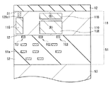
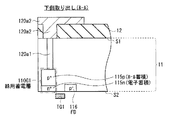
図3は、緑用蓄電層110Gの構成を表したものである。緑用蓄電層110Gは電子蓄積層となるn型領域115nを含んでおり、このn型領域115nは導電性プラグ120a1に接続されている。導電性プラグ120a1は半導体基板11に埋設されており、有機光電変換部11Gと緑用蓄電層110Gとの間の信号電荷(電子)の伝送経路として機能する。即ち、下部電極14から導電性プラグ120a1を介して伝送される電子が緑用蓄電層110Gに蓄積されるようになっている。半導体基板11の面S2近傍には緑色用の転送トランジスタTr1のフローティングディフュージョン(FD116)が設けられ、このFD116にn型領域115nが接続されている。n型領域115nと半導体基板11の面S2との間にはp型領域115p(ホール蓄積層)が設けられている。
FIG. 3 shows the configuration of the green
導電性プラグ120a1は例えば導電型の半導体層により構成され、半導体基板11に埋め込み形成されている。導電性プラグ120a1は電子の伝送経路となるのでn型半導体によりそれぞれ構成することが好ましい。あるいは、貫通ビアに例えばタングステン等の導電材料を埋設して導電性プラグ120a1を構成するようにしてもよい。このような導電性プラグ120a1では、これらとシリコンとの短絡を抑えるため、酸化シリコン(SiO2)または窒化シリコン(SiN)等の絶縁膜でビアの側面を覆っておくことが好ましい。
The conductive plug 120a1 is formed of, for example, a conductive semiconductor layer and is embedded in the
多層配線層51は半導体基板11の面S2に接して設けられている(図1)。この多層配線層51は層間絶縁膜52を介して複数の配線51aを有するものである。多層配線層51は例えば、シリコンからなる支持基板53に貼り合わされており、支持基板53と半導体基板11との間に多層配線層51が配置される。
The
有機光電変換部11Gは有機半導体材料からなる有機光電変換層16により、選択的な波長域の光(ここでは緑色光)を吸収して、電子・ホール対を発生させる光電変換素子である。有機光電変換部11G上には、保護膜19および平坦化層20を間にしてオンチップレンズ21が設けられており、このオンチップレンズ21を介して有機光電変換部11Gに光が入射する。有機光電変換部11Gで発生した信号電荷(電子)は下部電極14により取り出され、ホールは上部電極17を介して排出される。
The organic
有機光電変換部11Gは受光面となる半導体基板11の面S1上に、層間絶縁層12を間にして形成されている。このように、多層配線層51が設けられた半導体基板11の面S2と反対側の面S1に有機光電変換部11Gを設けて裏面照射型とすることにより、3つの光電変換部(有機光電変換部11Gおよび無機光電変換部11B,11R)間の感度の違いを小さくすることが可能となる。詳細には、半導体基板11の面S1上の有機光電変換部11Gと半導体基板11の内部の無機光電変換部11B,11Rとの間に、多層配線層51が設けられていないので、同一画素内の有機光電変換部11Gと無機光電変換部11B,11Rとの間の距離が狭まる。従って、オンチップレンズ21のF値に依存して生じる各色間の感度のばらつきが軽減される。
The organic
層間絶縁層12は半導体基板11(シリコン層110)の界面準位を低減すると共にシリコン層110との界面からの暗電流の発生を抑制する。このような層間絶縁層12には界面準位の低い絶縁材料を用いることが好ましく、例えばハフニウム酸化膜(HfO2)と酸化シリコン膜(SiO2)との積層膜により構成されている。層間絶縁膜12には、導電性プラグ120a1と対向する領域に貫通孔が設けられ、この貫通孔に導電性プラグ120a2が埋設されている。導電性プラグ120a2は、遮光機能を有していることが好ましく、例えばバリアメタルとなるチタン(Ti)と窒化チタン(TiN)との積層膜およびタングステンにより導電性プラグ120a2を構成するようにしてもよい。
The interlayer insulating
層間絶縁層12上には、有機光電変換部11Gの下部電極14が設けられている。この下部電極14は無機光電変換部11B,11Rの受光面と正対、即ち無機光電変換部11B,11Rの直上に設けられており、光透過性の導電材料、例えばITO(Indium-Tin-Oxide)により構成される。下部電極14は、例えば酸化スズ(SnO2)系材料または酸化亜鉛(ZnO)系材料により構成するようにしてもよい。酸化スズ系材料とは酸化スズにドーパントを添加したものであり、酸化亜鉛系材料とは例えば、酸化亜鉛にドーパントとしてアルミニウム(Al)を添加したアルミニウム亜鉛酸化物(AZO),酸化亜鉛にドーパントとしてガリウム(Ga)を添加したガリウム亜鉛酸化物(GZO)および酸化亜鉛にドーパントとしてインジウム(In)を添加したインジウム亜鉛酸化物(IZO)等である。この他、IGZO,CuI,InSbO4,ZnMgO,CuInO2,MgIn2O4,CdOおよびZnSnO3等を用いることも可能である。
On the
上述のように、撮像素子10では下部電極14から信号電荷の取り出しがなされるので、この撮像素子10を画素として用いた撮像装置(例えば後述の図18の撮像装置1)では、下部電極14は画素間絶縁膜15により画素毎に分離される。画素間絶縁膜15は、例えば、酸化シリコン,窒化シリコンおよび酸窒化シリコン(SiON)等のうちの1種よりなる単層膜、あるいは、これらのうちの2種以上よりなる積層膜により構成されている。この画素間絶縁膜15により、各画素の下部電極14が電気的に分離される。画素間絶縁膜15の表面は、例えば下部電極14の表面と略同じ位置で配置されており、平坦化されている。
As described above, since the signal charge is taken out from the
画素間絶縁膜15には配線13aが埋設されており、この配線13aの一方は、導電性プラグ120a2、他方は下部電極14に電気的に接続されている。即ち、下部電極14から取り出された電子は、配線13aおよび導電性プラグ120a1,120a2を介して緑用蓄電層110Gに蓄積される。配線13aは、例えば、タングステン(W),チタン(Ti),窒化チタン(TiN)またはアルミニウム(Al)等により構成されている。導電性プラグ120a2と同様に、配線13aは遮光性を有することが好ましく、例えば、チタンと窒化チタンとの積層膜およびタングステンにより構成される。
A
有機光電変換層16は、特定の波長域の光(緑色光)を光電変換し、それ以外の他の波長域の光を透過する有機半導体により構成されている。有機光電変換層16の構成材料は、この他の波長域の光に対して70%以上の透過率を有することが好ましい。有機光電変換層16は下部電極14と同様に、画素毎に分離されている。平面視で、有機光電変換層16は例えば下部電極14の周囲に拡幅している。
The organic
有機光電変換層16にはn型半導体16Nおよびp型半導体16Pが共に含まれていることが好ましい。有機光電変換層16には、例えばn型半導体16Nとp型半導体16Pとの混合層(共蒸着層16PN)が含まれている。n型半導体16Nおよびp型半導体16Pを両方含んでいることにより、pn接合面が生じ、所謂pinバルクヘテロ構造が形成される。従って、有機光電変換層16内でpn接合面が増加し、光電変換効率をより向上させることができる。
The organic
下部電極14にはn型半導体16N、上部電極17にはp型半導体層16Pがそれぞれ接していることが好ましい。このように有機光電変換層16を構成することにより、共蒸着層16PNで生じた電子・ホール対のうち、電子はn型半導体16Nを介して下部電極14に、ホールはp型半導体層16Pを介して上部電極17に移動する。従って、信号電荷が移動し易くなり、光電変換効率が向上する。下部電極14にp型半導体層16P、上部電極17にn型半導体16Nがそれぞれ接するようにしてもよい。このとき、共蒸着層16PNで生じた電子・ホール対のうち、電子はn型半導体16Nを介して上部電極17に、ホールはp型半導体層16Pを介して下部電極14に移動する。有機光電変換層16は、n型半導体16Nおよびp型半導体16Pが含まれていれば、n型半導体層16Nとp型半導体層16Pとを積層させて構成するようにしてもよい。あるいは、n型半導体層16Nおよびp型半導体層16Pのうち、どちらか一方のみを用いて有機光電変換層16を構成することも可能である。下部電極14とn型半導体16Nとの間にp型ブロッキング層(図示せず)、上部電極17とp型半導体16Pとの間にn型ブロッキング層(図示せず)をそれぞれ設けることが好ましい。p型ブロッキング層は下部電極14からホールが、n型ブロッキング層は上部電極17から電子がそれぞれ注入されて暗電流が発生するのを抑えるために設けられる。下部電極14の凹凸をなだらかにするための下引き膜(図示せず)、上部電極17を形成する際の劣化を抑制するためのバッファ膜(図示せず)および上部電極17の仕事関数を調整して暗電流の発生を抑制するための仕事関数調整膜(図示せず)等を設けるようにしてもよい。
It is preferable that the n-
n型半導体16Nおよびp型半導体16Pには、例えばキナクリドン誘導体,ナフタレン誘導体,アントラセン誘導体,フェナントレン誘導体,テトラセン誘導体,ピレン誘導体,ペリレン誘導体およびフルオランテン誘導体のいずれかを用いることが好ましい。n型半導体16Nおよびp型半導体16Pとしてフェニレンビニレン,フルオレン,カルバゾール,インドール,ピレン,ピロール,ピコリン,チオフェン,アセチレン,ジアセチレン等の重合体またはその誘導体等を用いることも可能である。金属錯体色素,シアニン系色素,メロシアニン系色素,フェニルキサンテン系色素,トリフェニルメタン系色素,ロダシアニン系色素,キサンテン系色素,大環状アザアヌレン系色素,アズレン系色素,ナフトキノンまたはアントラキノン系色素を用いてもよい。金属錯体色素としては、ジチオール金属錯体系色素,金属フタロシアニン色素,金属ポルフィリン色素およびルテニウム錯体色素を用いることが好ましく、中でもルテニウム錯体色素が特に好ましい。n型半導体16Nおよびp型半導体16Pを、アントラセンまたはピレン等の縮合多環芳香族、あるいは芳香環または複素環化合物が縮合した鎖状化合物により構成することも可能である。スクアリリウム基およびクロコニツクメチン基を結合鎖としてキノリン,ベンゾチアゾールまたはベンゾオキサゾール等の含窒素複素環を二以上結合させた化合物、または、スクアリリウム基およびクロコニツクメチン基により結合したシアニン系類似の色素等を用いるようにしてもよい。
For the n-
上部電極17は、有機光電変換層16を間にして下部電極14に対向しており、その平面形状は有機光電変換層16の平面形状と略同じである。有機光電変換層16のうち、この上部電極17との対向面が光入射面となる。上部電極17は、下部電極14と同様に光透過性の導電材料により構成されている。
The
本実施の形態では、この有機光電変換部11Gの上部電極17上に紫外線吸収膜18が設けられている。即ち、有機光電変換層16の光入射面は紫外線吸収膜18により覆われている。詳細は後述するが、これにより、有機光電変換層16をパターニングする際に、例えばプラズマ照射等を行うことが可能となり、有機光電変換層16の形状を精確に制御し易くなる。よって、撮像素子10により構成された画素の微細化を行うことが可能となる。
In the present embodiment, an
紫外線吸収膜18は、撮像素子1を形成する際に生じる紫外線が有機光電変換層16に到達するのを防ぐためのものであり、例えば波長400nm以下の光を吸収する。
The
図4は、紫外線吸収膜18の光吸収特性の一例を表したものである。このように、紫外線吸収膜18では、波長400nm以下の光の透過率が略80%以下であることが好ましい。紫外線吸収膜18は、波長400nm以下の波長域の光全てを吸収してもよく、あるいはその一部の波長域の光を吸収してもよい。例えば90%以上の可視光は紫外線吸収膜18を透過して、有機光電変換部11Gおよび無機光電変換部11B,11Rに達するようになっている。紫外線吸収膜18の可視光に対する透過率は80%以上であることが好ましい。紫外線吸収膜18には、例えば、窒化シリコン(SiN),酸化シリコン(SiO),酸窒化シリコン(SiON),酸化アルミニウム(AlO)および窒化アルミニウム(AlN)等を用いることができる。紫外線吸収膜18は、これらの単層膜によって構成するようにしてもよく、あるいは、2種類以上の膜を積層させて構成するようにしてもよい。紫外線吸収膜18には、波長400nm以下の光を一部反射するようなものを用いるようにしてもよく、例えば紫外線吸収膜18に酸化チタン(TiO),酸化バナジウム(VO)および酸化クロム(CrO)等の金属酸化物を用いるようにしてもよい。紫外線吸収膜18の膜厚は例えば、10nm〜500nmである。
FIG. 4 shows an example of the light absorption characteristics of the
有機光電変換層16への負荷により膜剥がれ等が生じるのを抑えるため、紫外線吸収膜18の応力は小さいことが好ましい。紫外線吸収膜18の応力は、引張応力、圧縮応力のどちらであってもよいが、その絶対値が例えば500MPa以下であることが好ましい。紫外線吸収膜18に開口等を設けることにより応力を緩和するようにしてもよい。
In order to prevent film peeling or the like from occurring due to a load on the organic
このような紫外線吸収膜18の平面形状は、上部電極17および有機光電変換層16の平面形状と略同じである。即ち、紫外線吸収膜18、上部電極17および有機光電変換層16の端部は、略揃っている。
The planar shape of such an
図5に示したように、紫外線吸収膜18、上部電極17および有機光電変換層16の端部の位置は互いにずれていてもよいが、例えば、紫外線吸収膜18、上部電極17および有機光電変換層16それぞれの端部は互いに500nm以内の範囲に設けられている。
As shown in FIG. 5, the positions of the end portions of the
保護膜19は、紫外線吸収膜18上から画素間絶縁膜15上にかけて設けられ、紫外線吸収膜18の上面から紫外線吸収膜18、上部電極17および有機光電変換層16の側面を覆っている。この保護膜19には上部電極17に電気的に接続された配線13bが埋設されている。配線13bの一方は、例えば紫外線吸収膜18の接続孔を介して上部電極17に電気的に接続され、配線13bの他方は、例えば図示しないコンタクト部を介して、多層配線層51の配線51aに電気的に接続されている。これにより、有機光電変換層16で発生したホールが上部電極17および配線13bを介して、排出されるようになっている。配線13bには、配線13aと同様の材料を用いることができる。保護膜19は光透過性を有し、例えば窒化シリコン,酸化シリコンおよび酸窒化シリコン等の単層膜あるいはこれらの積層膜により構成されている。保護膜19の厚みは、例えば100nm〜300nmである。
The
保護膜19上の全面にわたり平坦化層20が設けられており、この平坦化層20上にオンチップレンズ21が設けられている。オンチップレンズ21は、その上方から入射した光を有機光電変換部11Gおよび無機光電変換部11B,11Rの受光面に集光させるものである。上述のように、裏面照射型の撮像素子10では、オンチップレンズ21と無機光電変換部11B,11Rの受光面との距離が近くなるので、オンチップレンズ21のF値に依存して生じる各色の感度のばらつきを抑えることができる。平坦化層20は、例えば、アクリル系樹脂材料,スチレン系樹脂材料およびエポキシ系樹脂材料等により構成されている。
A
[撮像素子10の製造方法]
このような撮像素子10は、例えば以下のようにして製造することができる(図6A〜図10D)。
[Method for Manufacturing Image Sensor 10]
Such an
まず、半導体基板11を形成する。半導体基板11は、まず、図6Aに示したように、シリコン基体1101とシリコン層110との間にシリコン酸化膜1102を有する基板(所謂SOI基板)を準備し、シリコン層110に導電性プラグ120a1を形成する。シリコン層110のうち、シリコン酸化膜1102との接触面が半導体基板11の面S1となる。導電性プラグ120a1は、例えば、シリコン層110に貫通ビアを形成し、この貫通ビア内に窒化シリコン等の絶縁膜およびタングステンを埋め込んで形成する。あるいは、導電性プラグ120a1として、シリコン層110へのイオン注入により導電型不純物半導体層を形成するようにしてもよい。次いで、シリコン層110内の深さの異なる領域に、互いに重畳するようにして、無機光電変換部11B,11Rを形成する。無機光電変換部11B,11Rと共にイオン注入により緑用蓄電層110Gを形成しておく(図6B)。半導体基板11の面S2近傍には、転送トランジスタTr1,Tr2,Tr3等の画素トランジスタおよびロジック回路等の周辺回路を設ける。これにより半導体基板11が形成される。
First, the
続いて、図7に示したように、半導体基板11の面S2上に多層配線層51を形成する。多層配線層51には層間絶縁膜52を介して複数の配線51aを設ける。次いで、多層配線層51に支持基板53を貼り付けた後、シリコン層110からシリコン酸化膜1102およびシリコン基体1101を剥離してシリコン層110の面S1を露出させる(図8)。その後、図9に示したように、この半導体基板11の面S1上に例えば原子層堆積(ALD:Atomic Layer Deposition)法により
ハフニウム酸化膜、プラズマCVD(Chemical Vapor Deposition)法により酸化シリコン膜をこの順に成膜して層間絶縁層12を形成する。
Subsequently, as shown in FIG. 7, the
次いで、この層間絶縁層12のうち、導電性プラグ120a1に対向する位置に接続孔を設けた後、層間絶縁層12上に導電膜を成膜してこの接続孔に導電材料を埋め込む。これにより、導電性プラグ120a2が形成される。層間絶縁層12上の導電膜は所望の形状にパターニングし、導電性プラグ120a2と共に配線13aを形成しておく(図示せず)。
Next, after a connection hole is provided in the
続いて、層間絶縁層12上に下部電極14を形成する。下部電極14は、例えばスパッタ法により厚み50nmのITO膜を成膜した後、これをフォトリソグラフィ技術によりパターニングしてドライエッチングまたはウェットエッチングを行うことにより形成する。下部電極14を形成した後、下部電極14上および層間絶縁層12上に、例えばプラズマCVD法により酸化シリコン膜を成膜して画素間絶縁膜15を形成する。画素間絶縁膜15は例えばCMP(Chemical Mechanical Polishing)等により平坦化しておく(図10A)。図10Aでは、支持基板53、多層配線層51および半導体基板11の図示を省略している。以降、図10B〜図10Dについても同様である。
Subsequently, the
画素間絶縁膜15を設けた後、例えば半導体基板11の全面に真空蒸着法または塗布法により有機光電変換材料膜16Aを成膜する。有機光電変換材料膜16Aは、例えばn型半導体16Nおよびp型半導体16Pを含んでいる。次いで、有機光電変換材料膜16A上の全面に、透明導電膜17Aおよび紫外線吸収材料膜18Aをこの順に成膜する(図10B)。有機光電変換材料膜16Aは、水分、酸素および水素等の影響を受けて特性が変化し易い。このため、透明導電膜17Aは、有機光電変換材料膜16Aと真空雰囲気中で連続して(真空一貫プロセスで)成膜することが好ましい。透明導電膜17Aは、例えばスパッタ法により成膜する。紫外線吸収材料膜18Aは、例えばCVD(Chemical Vapor Deposition)法により成膜する。例えば、以下のような条件で窒化シリコン膜からなる紫外線吸収材料膜18Aを成膜することが可能である。並行平板型のプラズマCVD装置を用いて、RFパワー500W、基板温度200℃、圧力5Torr、窒素(N2)流量5000sccm、シラン(SiH4)流量500sccm、アンモニア(NH3)流量100sccmの条件下、紫外線吸収材料膜18Aを成膜する。この紫外線吸収材料膜18Aは、上述の図4に示した光吸収特性を示す。
After providing the
紫外線吸収材料膜18Aを設けた後、紫外線吸収材料膜18A上に所定パターンのレジスト膜31を形成して(図10C)、紫外線吸収材料膜18A、透明導電膜17Aおよび有機光電変換材料膜16Aをパターニングする。これにより、互いに平面形状が略同一の紫外線吸収膜18、上部電極17および有機光電変換層16が形成される(図10D)。具体的には、フォトリソグラフィ技術を用いて所定パターンのレジスト膜31を形成した後、例えばプラズマ照射により、紫外線吸収材料膜18A、透明導電膜17Aおよび有機光電変換材料膜16Aのドライエッチングを行う。このとき、プラズマ照射により発生する紫外線は、紫外線吸収材料膜18Aに遮られるので、有機光電変換材料膜16Aには到達しにくくなる。ドライエッチングを行った後、アッシングおよび有機溶媒による洗浄等を行って、レジスト膜31に由来する堆積物および残渣物等を除去する。有機溶媒に代えて、希フッ酸等により洗浄するようにしてもよい。
After providing the ultraviolet absorbing
紫外線吸収膜18、上部電極17および有機光電変換層16を設けた後、配線13bおよび保護膜19を形成する。保護膜19は例えばプラズマCVD法により紫外線吸収膜18上に窒化シリコンまたは酸化シリコンを成膜して形成する。保護膜19を形成した後、保護膜19のうち上部電極17に対向する位置に紫外線吸収膜18を貫通する接続孔を形成する。次いで、この接続孔に埋め込むようにして、保護膜19上に配線13bを形成する。配線13bは、例えばフォトリソグラフィ技術およびエッチングを用いて形成することができる。次いで、保護膜19上に平坦化層20を形成した後、平坦化層20上にオンチップレンズ21を形成する。以上の工程により図1に示した撮像素子10が完成する。
After providing the
[撮像素子10の動作]
このような撮像素子10では、例えば撮像装置の画素として、次のようにして信号電荷(電子)が取得される。撮像素子10に、オンチップレンズ21(図1)を介して光Lが入射すると(図11)、光Lは有機光電変換部11G、無機光電変換部11Bおよび無機光電変換部11Rの順に通過し、その通過過程において緑、青、赤の色光毎に光電変換される。詳細には、図12に示したように、撮像素子10へ入射した光Lのうち、まず、緑色光Lgが有機光電変換部11Gで選択的に検出(吸収)され、光電変換される。有機光電変換部11Gで発生した電子・ホール対のうちの電子Egが下部電極14から取り出され、伝送経路A(配線13a,導電性プラグ120a1,120a2)を介して緑用蓄電層110Gへ蓄積される。蓄積された電子Egは、読み出し動作の際にFD116へ転送される。一方、ホールHgは上部電極17から伝送経路B(配線13b)を介して排出される。
[Operation of Image Sensor 10]
In such an
撮像素子10では、下部電極14に所定の負電位VL(<0V)が、上部電極17に電位VLよりも低い電位VU(<VL)がそれぞれ印加される。従って、電荷蓄積状態(リセットトランジスタ(図示せず)および転送トランジスタTr1のオフ状態)では、有機光電変換部11Gで発生した電子・ホール対のうち、電子が相対的に高電位となっている下部電極14に導かれる。この下部電極14から電子Egが取り出され、伝送経路Aを介して緑用蓄電層110G(詳細にはn型領域115n)に蓄積される。電子Egが蓄積されると、緑用蓄電層110Gと導通した下部電極14の電位VLが変動する。この電位VLの変化量が信号電位(ここでは、緑色信号の電位)に相当する。なお、電位VLは例えば多層配線層51の配線51aから伝送経路Aを通じて下部電極14に、電位VUは例えば多層配線層51の配線51aから伝送経路Bを通じて上部電極17にそれぞれ与えられる。
In the
読み出し動作の際には、転送トランジスタTr1がオン状態となり、緑用蓄電層110Gに蓄積された電子EgがFD116に転送される。これにより、緑色光Lgの受光量に基づく緑色信号が、例えば画素トランジスタ(図示せず)を通じて垂直信号線Lsig(後述の図20)に読み出される。その後、リセットトランジスタ(図示せず)および転送トランジスタTr1がオン状態となり、n型領域であるFD116と緑用蓄電層110Gの蓄電領域(n型領域115n)とが例えば電源電圧VDDにリセットされる。
During the read operation, the transfer transistor Tr1 is turned on, and the electrons Eg accumulated in the green
有機光電変換部11Gを透過した光のうち、青色光は無機光電変換部11B、赤色光は無機光電変換部11Rに吸収され、光電変換される。無機光電変換部11Bでは、入射した青色光に対応した電子Ebがn型領域(n型光電変換層111n)に蓄積される。この蓄積された電子Ebは、読み出し動作の際にFD113へと転送される。このとき無機光電変換部11Bで発生したホールはp型領域(図12には図示せず)に蓄積される。無機光電変換部11Rも同様である。無機光電変換部11Rでは、入射した赤色光に対応した電子Erがn型領域(n型光電変換層112n)に蓄積される。この蓄積された電子Erは、読み出し動作の際にFD114へと転送される。このとき無機光電変換部11Rで発生したホールはp型領域(図12には図示せず)に蓄積される。
Of the light transmitted through the organic
電荷蓄積状態では、上述のように、下部電極14に負の電位VLが印加されるので、無機光電変換部11Bのホール蓄積層であるp型領域(図2のp型領域111p)の正孔濃度が増加しやすい。これにより、p型領域111と層間絶縁層12との界面での暗電流の発生を抑えることができる。
In the charge accumulation state, as described above, since the negative potential VL is applied to the
無機光電変換部11B,11Rの読み出し動作は、上記有機光電変換部11Gと同様に行われる。転送トランジスタTr2,Tr3がオン状態となり、n型光電変換層111n,112nに蓄積された電子Eb,ErがFD113,114に転送される。これにより、青色光Lbの受光量に基づく青色信号と赤色光Lrの受光量に基づく赤色信号とが例えば画素トランジスタ(図示せず)を通じて垂直信号線Lsig(後述の図20)に読み出される。その後、リセットトランジスタ(図示せず)および転送トランジスタTr2,Tr3がオン状態となり、n型領域であるFD113,114が例えば電源電圧VDDにリセットされる。
The readout operation of the inorganic
[撮像素子10の作用・効果]
このように、縦方向に有機光電変換部11Gおよび無機光電変換部11B,11Rを積み重ねることにより、カラーフィルタを設けることなく、赤,緑,青の色光を分離して検出し、各色の信号電荷を得ることができる。従って、カラーフィルタの色光吸収に起因する光損失(感度低下)や、画素補間処理に伴う偽色の発生を抑制することが可能となる。
[Operation / Effect of Image Sensor 10]
In this way, by stacking the organic
撮像素子10では、有機光電変換層16の光入射面が紫外線吸収膜18で覆われているので、有機光電変換部11Gの形状を精確に制御することができる。以下、これについて説明する。
In the
図13A,図13Bは比較例に係る撮像素子の製造工程を表したものである。この撮像素子の製造方法では、まず、メタルマスク32を半導体基板上に配置した後、蒸着法を用いてメタルマスク32の開口部に有機光電変換層160を形成する(図13A)。次いで、この有機光電変換層160との合わせずれを考慮して、メタルマスク33を配置した後、有機光電変換層160上に上部電極170を形成する(図13B)。このとき、例えば上部電極170は有機光電変換層160の周囲に拡幅し、有機光電変換層160の周縁は上部電極170で覆われる。このような、メタルマスク32,33を用いて有機光電変換部を形成する方法では、マスク間の合わせずれを考慮したマージン部分が大きくなりやすく、精確に有機光電変換部の形状を制御することが困難である。例えば、メタルマスク32,33を用いたときの有機光電変換部のマージン部分は、片側で500μm程度であり、マージン部分全体の大きさは例えば約1000μmである。
13A and 13B show the manufacturing process of the image sensor according to the comparative example. In this imaging device manufacturing method, first, a
例えば、ドライエッチング法を用いることにより、精確、かつ容易に有機光電変換層をパターニングすることが可能である。フォトリソグラフィ技術およびドライエッチングにより有機光電変換層を形成しても、合わせずれおよびサイドエッチングによりマージン部分は生じるが、例えば、その大きさは片側0.5μm程度である。即ち、メタルマスク32,33を用いたときの有機光電変換部のマージン部分の大きさの1000分の1程度に抑えられる。しかしながら、ドライエッチング法ではプラズマを使用するため、プラズマにより紫外線が発生する。この紫外線が有機光電変換層に入射すると、有機光電変換層の量子効率を低下させる虞がある。 For example, the organic photoelectric conversion layer can be patterned accurately and easily by using a dry etching method. Even when the organic photoelectric conversion layer is formed by photolithography and dry etching, a margin portion is generated due to misalignment and side etching, but the size is, for example, about 0.5 μm on one side. That is, the size of the margin portion of the organic photoelectric conversion unit when the metal masks 32 and 33 are used can be suppressed to about 1/1000. However, since dry etching uses plasma, ultraviolet rays are generated by the plasma. When this ultraviolet light is incident on the organic photoelectric conversion layer, the quantum efficiency of the organic photoelectric conversion layer may be reduced.
これに対し、撮像素子10では有機光電変換層16の光入射面が紫外線吸収膜18で覆われているので、紫外線が発生しても有機光電変換層16への到達前に紫外線は遮断される。即ち、有機光電変換層16のパターニングにドライエッチングを用いても、有機光電変換層16の量子効率の低下を防ぐことができる。撮像素子10では、紫外線吸収膜18を設けずにドライエッチングを行った場合に比べて、約2.8倍量子効率が向上する(電界強度0.1mV/cm)。これは、上記図13Aおよび図13Bに示した方法で形成した有機光電変換部の量子効率と略同等である。このように、有機光電変換部11Gの形状を精確に制御して、画素の微細化を行うことが可能となる。
On the other hand, since the light incident surface of the organic
また、有機光電変換部11Gを形成した後の工程においても、紫外線吸収膜18により、紫外線は有機光電変換層16への到達前に遮断される。よって、有機光電変換層16の劣化が抑えられ、撮像素子10の歩留まりが安定化する。
Also in the process after the formation of the organic
以上説明したように、本実施の形態では、有機光電変換層16の光入射面を紫外線吸収膜18で覆うようにしたので、撮像素子10により構成した画素の微細化を行うことができる。
As described above, in the present embodiment, since the light incident surface of the organic
以下、上記実施の形態の変形例および他の実施の形態について説明するが、以降の説明において上記実施の形態と同一構成部分については同一符号を付してその説明は適宜省略する。 Hereinafter, modifications of the above-described embodiment and other embodiments will be described. In the following description, the same components as those of the above-described embodiment will be denoted by the same reference numerals, and the description thereof will be omitted as appropriate.
<変形例1>
図14は、上記実施の形態の変形例1に係る撮像素子(撮像素子10A)の断面構成を表したものである。この撮像素子10Aは、半導体基板11上に有機光電変換部11Gと共に有機光電変換部11BA,11RAを有している。この点を除き、撮像素子10Aは撮像素子10と同様の構成を有し、その作用および効果も同様である。
<
FIG. 14 illustrates a cross-sectional configuration of an imaging element (imaging element 10A) according to
この撮像素子10Aでは、半導体基板11の内部に光電変換部(図1の無機光電変換部11B,11R)が設けられておらず、半導体基板11上に複数の有機光電変換部11G,11BA,11RAが設けられている。この有機光電変換部11G,11BA,11RAは、半導体基板11上に、例えば有機光電変換部11RA、有機光電変換部11Gおよび有機光電変換部11BAの順に配置されている。即ち、オンチップレンズ21を介して入射した光は、有機光電変換部11BA、有機光電変換部11Gおよび有機光電変換部11RAの順に通過する。
In the imaging element 10A, the photoelectric conversion units (inorganic
有機光電変換部11BA,11RAは、有機光電変換部11Gと同様に、それぞれ下部電極14B,14R、有機光電変換層16B,16Rおよび上部電極17B,17Rを有している。下部電極14B,14Rは画素間絶縁膜15B,15Rで分離されている。有機光電変換部11Gの有機光電変換層16と同様に、有機光電変換部11BA,11RAの有機光電変換層16B,16Rも、それぞれの光入射面が紫外線吸収膜18B,18Rにより覆われている。有機光電変換部11G,11BA,11RAのうち、最初に光が入射する有機光電変換部11BAのみに紫外線吸収膜18Bを設けることも可能であるが、有機光電変換部11G,11BA,11RAそれぞれに紫外線吸収膜18,18B,18Rを設けることが好ましい。このような場合にも、上記第1の実施の形態と同様に、有機光電変換層16B,16Rをパターニングする際に、ドライエッチングを用いることが可能となる。よって、撮像素子10Aにより構成した画素の微細化を行うことが可能となる。
Similarly to the organic
撮像素子10Aでは、半導体基板11に代えて、ガラス等からなる透明基板を用いることが可能である。樹脂材料によりこの透明基板を構成するようにしてもよく、樹脂材料には例えば、ポリエチレンテレフタレート,ポリイミド,ポリエーテルサルフォンおよびポリカーボネート等を用いることが可能である。
In the
<変形例2>
図15に示したように、下部電極14から信号電荷としてホールを取り出して緑色蓄電層(緑用蓄電層110G1)に蓄積するようにしてもよい(変形例2)。
<
As shown in FIG. 15, holes may be taken out as signal charges from the
このような撮像素子10では、半導体基板11の面S1上の各部の構成は上記第1の実施の形態と同じであるが、半導体基板11内の緑用蓄電層110G1およびフローティングディフュージョン(FD116a)の構成が異なる。緑用蓄電層110G1ではホール蓄積層のp型領域115pが導電性プラグ120a1に接続され、p型領域115pと半導体基板11の面S2との間に電子蓄積層のn型領域115nが設けられている。FD116aはp型領域として形成される。
In such an
緑用蓄電層110G1には、以下のようにしてホールが蓄積される。下部電極14に、上部電極17よりも低い電位VLが印加されると、有機光電変換部11Gで生じた電子・ホール対のうち、ホールが下部電極14に導かれる。このホールは配線13a(図1)および導電性プラグ120a1,120a2を通じて緑用蓄電層110G1のp型領域115pに蓄積される。読み出し動作の際には、この蓄積されたホールがFD116aに転送される。
Holes are accumulated in the green power storage layer 110G1 as follows. When a potential VL lower than that of the
<変形例3>
図16に示したように、上部電極17から信号電荷を取り出すようにしてもよい(変形例3)。
<Modification 3>
As shown in FIG. 16, signal charges may be taken out from the upper electrode 17 (Modification 3).
このような撮像素子10では、半導体基板11内の緑色蓄電層(緑用蓄電層110G2)が導電性プラグ120a1に接続され、更に、導電性プラグ120a2および配線13cを介して上部電極17に電気的に接続されている。緑用蓄電層110G2およびフローティングディフュージョンの構成を上記第1の実施の形態と同様に構成することにより、上部電極17から信号電荷として電子を取り出して緑用蓄電層110G2に蓄積することが可能となる。このとき、上部電極17への印加電位は下部電極14への印加電位よりも高く設定する。ホールは下部電極14から図示しない配線を介して排出される。
In such an
一方、緑用蓄電層110G2およびフローティングディフュージョンの構成を上記変形例2と同様に構成することにより、上部電極17から信号電荷としてホールを取り出して緑用蓄電層110G2に蓄積することが可能となる。このとき、上部電極17への印加電位は下部電極14への印加電位よりも低く設定する。電子は下部電極14から図示しない配線を介して排出される。
On the other hand, by configuring the green power storage layer 110G2 and the floating diffusion in the same manner as in the second modification, holes can be taken out as signal charges from the
<第2の実施の形態>
図17は、本技術の第2の実施の形態に係る撮像素子(撮像素子60)の断面構成を表したものである。この撮像素子60は、有機光電変換層16上に紫外線反射膜(紫外線反射膜68)を有するものである。この点を除き、撮像素子60は撮像素子10と同様の構成を有し、その作用および効果も同様である。
<Second Embodiment>
FIG. 17 illustrates a cross-sectional configuration of an imaging device (imaging device 60) according to the second embodiment of the present technology. This image sensor 60 has an ultraviolet reflective film (ultraviolet reflective film 68) on the organic
紫外線反射膜68は、撮像素子10の紫外線吸収膜18(図1)と同様に、上部電極17を間にして有機光電変換層16の光入射面を覆っており、有機光電変換層16への紫外線の入射を遮断する。このような紫外線反射膜68は、例えば波長400nm以下の光に対して高い反射率を有しており、例えばアルミニウム(Al),チタン(Ti),タングステン(W)または窒化チタン(TiN)等により構成される。このような場合にも、上記第1の実施の形態と同様に、有機光電変換層16をパターニングする際に、ドライエッチングを用いることが可能となる。よって、撮像素子60により構成した画素の微細化を行うことが可能となる。
The ultraviolet reflecting film 68 covers the light incident surface of the organic
<適用例>
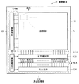
図18は上記実施の形態および変形例で説明した撮像素子(撮像素子10,10A,60)を各画素に用いた固体撮像装置(撮像装置1)の全体構成を表している。この撮像装置1はCMOSイメージセンサであり、半導体基板11上の中央部に撮像エリアとしての画素部1aを有している。画素部1aの周辺領域には、例えば行走査部131、システム制御部132、水平選択部133および列走査部134を含む周辺回路部130が設けられている。
<Application example>
FIG. 18 illustrates the overall configuration of a solid-state imaging device (imaging device 1) that uses the imaging device (
画素部1aは、例えば行列状に2次元配置された複数の単位画素P(撮像素子10,10A,10Bに相当)を有している。この単位画素Pには、例えば画素行ごとに画素駆動線Lread(具体的には行選択線およびリセット制御線)が、画素列ごとに垂直信号線Lsigが配線されている。画素駆動線Lreadは、画素からの信号読み出しのための駆動信号を伝送するものであり、その一端は行走査部131の各行に対応した出力端に接続されている。
The
行走査部131は、シフトレジスタやアドレスデコーダ等によって構成され、画素部1aの各画素Pを例えば行単位で駆動する画素駆動部である。行走査部131によって選択された画素行の各画素Pから出力される信号は、垂直信号線Lsigの各々を通じて水平選択部133に供給される。水平選択部133は、例えば垂直信号線Lsigごとに設けられたアンプや水平選択スイッチ等により構成されている。
The
列走査部134は、シフトレジスタやアドレスデコーダ等によって構成され、水平選択部133の各水平選択スイッチを走査しつつ順番に駆動するものである。この列走査部134による選択走査により、垂直信号線Lsigの各々を通じて伝送される各画素Pの信号が順番に水平信号線135に出力され、当該水平信号線135を通じて半導体基板11の外部へ伝送される。
The
行走査部131、水平選択部133、列走査部134および水平信号線135からなる回路部分は、半導体基板11上に直に形成されていてもよいし、あるいは外部制御ICに配設されたものであってもよい。ケーブル等により接続された他の基板にこの回路部分を設けることも可能である。
The circuit portion including the
システム制御部132は、半導体基板11の外部から与えられるクロックや動作モードを指令するデータなどを受け取ると共に、撮像装置1の内部情報を出力するものである。システム制御部132は、これに加え、例えば各種のタイミング信号を生成するタイミングジェネレータを有し、当該タイミングジェネレータで生成された各種のタイミング信号を基に行走査部131、水平選択部133および列走査部134などの周辺回路の駆動制御を行う。
The
このような撮像装置1は、撮像機能を有するあらゆるタイプの電子機器に搭載でき、例えばデジタルスチルカメラやビデオカメラ等のカメラシステムや、携帯電話などに適用できる。図19には、その一例として、カメラ(電子機器2)の概略構成を示す。電子機器2は、例えば静止画または動画を撮影可能なビデオカメラであり、撮像装置1、光学系(光学レンズ)310、シャッタ装置311、信号処理部312および駆動部313を有している。
Such an
光学系310は、被写体からの像光(入射光)を撮像装置1の画素部1aへと導くものである。光学系310は複数の光学レンズを含んでいてもよい。シャッタ装置311は撮像装置1への光照射期間および遮光期間を制御し、駆動部313は、このシャッタ装置311のシャッタ動作および撮像装置1の転送動作を制御する。信号処理部312は、撮像装置1から出力された信号に対し、各種の信号処理を行うものである。信号処理後の映像信号Doutは、例えばメモリなどの記憶媒体に記憶されるか、あるいはモニタ等に出力されるようになっている。
The
以上、実施の形態および変形例を挙げて本技術を説明したが、本技術は上記実施の形態等に限定されるものではなく、種々変形が可能である。例えば、上記実施の形態等では、撮像素子10,60として、緑色光を検出する有機光電変換部11Gと、赤色光および青色光を検出する無機光電変換部11B,11Rとを積層させて場合について説明したが、本技術はこの構成に限定されるものではない。例えば、有機光電変換部で赤色光または青色光を検出するようにしてもよく、無機光電変換部で緑色光を検出するようにしてもよい。有機光電変換部、無機光電変換部の数やその比率も上記で説明した例に限定されるものではなく、例えば2以上の有機光電変換部を設けてもよい。光電変換部(有機光電変換部、無機光電変換部)を縦方向に積層させるだけでなく、半導体基板面に沿って並列に配置するようにしてもよい。
Although the present technology has been described with the embodiment and the modification, the present technology is not limited to the above-described embodiment and the like, and various modifications can be made. For example, in the above-described embodiment, as the
また、上記実施の形態等においては、裏面照射型の撮像素子10,10A,60の構成を例示したが、表面照射型に適用させることも可能である。
Moreover, in the said embodiment etc., although the structure of the back surface irradiation type image pick-up
更に、上記実施の形態等で説明した各構成要素を全て備えている必要はなく、また、他の構成要素を備えていてもよい。 Furthermore, it is not necessary to provide all the constituent elements described in the above embodiments and the like, and other constituent elements may be provided.
なお、本技術は以下の様な構成をとることも可能である。
(1)1または2以上の第1光電変換部と、前記第1光電変換部に対向する位置に設けられ、有機層を含むと共に最初に光が入射する第2光電変換部と、前記有機層の光入射面を覆う紫外線防止膜とを備えた固体撮像素子。
(2)前記第2光電変換部は、前記紫外線防止膜と前記有機層との間の上部電極と、前記上部電極に前記有機層を間にして対向する下部電極とを含む前記(1)に記載の固体撮像素子。
(3)前記紫外線防止膜、前記上部電極および前記有機層の平面形状が同一である前記(2)に記載の固体撮像素子。
(4)前記紫外線防止膜は、波長400nm以下の光の少なくとも一部を吸収する前記(1)乃至(3)のうちいずれか1つに記載の固体撮像素子。
(5)前記紫外線防止膜の波長400nm以下の光に対する透過率は80%以下である前記(4)に記載の固体撮像素子。
(6)前記紫外線防止膜は、可視光を透過する前記(1)乃至(5)のうちいずれか1つに記載の固体撮像素子。
(7)前記紫外線防止膜の可視光に対する透過率は80%以上である前記(6)に記載の固体撮像素子。
(8)前記紫外線防止膜の応力の絶対値は500MPa以下である前記(1)乃至(7)のうちいずれか1つに記載の固体撮像素子。
(9)前記紫外線防止膜は、窒化シリコン,酸化シリコン,酸窒化シリコン,酸化アルミニウム,窒化アルミニウム,酸化チタン,酸化バナジウムおよび酸化クロムのうち少なくともいずれか一つを含む前記(1)乃至(8)のうちいずれか1つに記載の固体撮像素子。
(10)基板を有し、前記第2光電変換部は前記基板上に設けられている前記(1)乃至(9)のうちいずれか1つに記載の固体撮像素子。
(11)前記基板の内部の、前記第2光電変換部と平面視で重なる位置に前記第1光電変換部を有する前記(10)に記載の固体撮像素子。
(12)前記紫外線防止膜は、波長400nm以下の光の少なくとも一部を反射する前記(1)乃至(11)のうちいずれか1つに記載の固体撮像素子。
(13)前記有機層は、第1導電型半導体および第2導電型半導体を含み、前記上部電極および下部電極の一方は前記第1導電型半導体、他方は前記第2導電型半導体にそれぞれ接している前記(2)に記載の固体撮像素子。
(14)前記第2光電変換部は特定の波長域の光を吸収する前記(1)乃至(13)のうちいずれか1つに記載の固体撮像素子。
(15)前記第2光電変換部は前記特定の波長域以外の光に対して70%以上の透過率を有する前記(14)に記載の固体撮像素子。
(16)固体撮像素子を有し、前記固体撮像素子は、1または2以上の第1光電変換部と、前記第1光電変換部に対向する位置に設けられ、有機層を含むと共に最初に光が入射する第2光電変換部と、前記有機層の光入射面を覆う紫外線防止膜とを備えた電子機器。
(17)1または2以上の第1光電変換部に対向する位置に、有機層を成膜することと、前記有機層の光入射面を紫外線防止膜で覆った後、前記有機層をパターニングして第2光電変換部を設けることとを含む固体撮像素子の製造方法。
In addition, this technique can also take the following structures.
(1) One or two or more first photoelectric conversion units, a second photoelectric conversion unit that is provided at a position facing the first photoelectric conversion unit, includes an organic layer, and first receives light, and the organic layer A solid-state imaging device comprising an ultraviolet ray preventing film that covers the light incident surface of the solid-state image sensor.
(2) In the above (1), the second photoelectric conversion unit includes an upper electrode between the ultraviolet protection film and the organic layer, and a lower electrode facing the upper electrode with the organic layer in between. The solid-state imaging device described.
(3) The solid-state imaging device according to (2), wherein the ultraviolet protection film, the upper electrode, and the organic layer have the same planar shape.
(4) The solid-state imaging device according to any one of (1) to (3), wherein the ultraviolet prevention film absorbs at least part of light having a wavelength of 400 nm or less.
(5) The solid-state imaging device according to (4), wherein the ultraviolet ray prevention film has a transmittance of 80% or less for light having a wavelength of 400 nm or less.
(6) The solid-state imaging device according to any one of (1) to (5), wherein the ultraviolet prevention film transmits visible light.
(7) The solid-state imaging device according to (6), wherein the ultraviolet light blocking film has a visible light transmittance of 80% or more.
(8) The solid-state imaging device according to any one of (1) to (7), wherein an absolute value of stress of the ultraviolet protection film is 500 MPa or less.
(9) The UV protection film includes at least one of silicon nitride, silicon oxide, silicon oxynitride, aluminum oxide, aluminum nitride, titanium oxide, vanadium oxide, and chromium oxide. The solid-state image sensor as described in any one of these.
(10) The solid-state imaging device according to any one of (1) to (9), further including a substrate, wherein the second photoelectric conversion unit is provided on the substrate.
(11) The solid-state imaging device according to (10), wherein the first photoelectric conversion unit is disposed at a position overlapping the second photoelectric conversion unit in plan view inside the substrate.
(12) The solid-state imaging device according to any one of (1) to (11), wherein the ultraviolet prevention film reflects at least a part of light having a wavelength of 400 nm or less.
(13) The organic layer includes a first conductivity type semiconductor and a second conductivity type semiconductor, wherein one of the upper electrode and the lower electrode is in contact with the first conductivity type semiconductor and the other is in contact with the second conductivity type semiconductor. The solid-state imaging device according to (2).
(14) The solid-state imaging device according to any one of (1) to (13), wherein the second photoelectric conversion unit absorbs light in a specific wavelength range.
(15) The solid-state imaging device according to (14), wherein the second photoelectric conversion unit has a transmittance of 70% or more with respect to light outside the specific wavelength range.
(16) It has a solid-state imaging device, and the solid-state imaging device is provided at one or two or more first photoelectric conversion units and a position facing the first photoelectric conversion unit, includes an organic layer, and is light first. An electronic apparatus comprising: a second photoelectric conversion unit on which the light enters; and an ultraviolet protection film covering a light incident surface of the organic layer.
(17) An organic layer is formed at a position facing one or more first photoelectric conversion units, and the light incident surface of the organic layer is covered with an ultraviolet protection film, and then the organic layer is patterned. And providing a second photoelectric conversion unit.
1…撮像装置、10,10A,60…撮像素子、11…半導体基板、11G,11BA,11RA…有機光電変換部、11B,11R…無機光電変換部、12…層間絶縁層、13a,13b…配線、14,14R,14B…下部電極、15,15R,15B…画素間絶縁膜、16…有機光電変換層、16P…P型半導体、16N…N型半導体、16PN…共蒸着層、17,17R,17B…上部電極、18,18R,18B…紫外線吸収膜、68…紫外線反射膜、19…保護膜、20…平坦化層、21…オンチップレンズ、51…多層配線層、53…支持基板、110…シリコン層、110G,110G1,110G2…緑用蓄電層、120a1,120a2…導電性プラグ。
DESCRIPTION OF
Claims (17)
前記第1光電変換部に対向する位置に設けられ、パターニングされた有機層を含むと共に最初に光が入射する第2光電変換部と、
前記有機層の光入射面を覆う紫外線防止膜とを備え、
前記第2光電変換部は、前記紫外線防止膜と前記有機層との間の上部電極と、前記上部電極に前記有機層を間にして対向する下部電極とを含み、
前記紫外線防止膜、前記上部電極および前記有機層の平面形状が同一である
固体撮像素子。 One or more first photoelectric conversion units;
A second photoelectric conversion unit that is provided at a position facing the first photoelectric conversion unit, includes a patterned organic layer, and first receives light;
An ultraviolet protection film covering the light incident surface of the organic layer ,
The second photoelectric conversion unit includes an upper electrode between the ultraviolet protection film and the organic layer, and a lower electrode facing the upper electrode with the organic layer in between,
The solid-state imaging device in which the ultraviolet ray prevention film, the upper electrode, and the organic layer have the same planar shape .
請求項1に記載の固体撮像素子。The solid-state imaging device according to claim 1.
請求項1または請求項2に記載の固体撮像素子。The solid-state image sensor of Claim 1 or Claim 2.
請求項1ないし請求項3のうちいずれか1項に記載の固体撮像素子。 The solid-state imaging device according to any one of claims 1 to 3, wherein the ultraviolet protection film absorbs at least part of light having a wavelength of 400 nm or less.
請求項4に記載の固体撮像素子。 The solid-state imaging device according to claim 4, wherein a transmittance of the ultraviolet prevention film with respect to light having a wavelength of 400 nm or less is 80% or less.
請求項1ないし請求項5のうちいずれか1項に記載の固体撮像素子。 The solid-state imaging device according to any one of claims 1 to 5 , wherein the ultraviolet protection film transmits visible light.
請求項6に記載の固体撮像素子。 The solid-state imaging device according to claim 6, wherein the ultraviolet light blocking film has a visible light transmittance of 80% or more.
請求項1ないし請求項7のうちいずれか1項に記載の固体撮像素子。 The solid-state image sensor according to any one of claims 1 to 7, wherein an absolute value of stress of the ultraviolet protection film is 500 MPa or less.
請求項1ないし請求項8のうちいずれか1項に記載の固体撮像素子。 9. The ultraviolet ray prevention film includes at least one of silicon nitride, silicon oxide, silicon oxynitride, aluminum oxide, aluminum nitride, titanium oxide, vanadium oxide, and chromium oxide . The solid-state imaging device according to item 1 .
前記第2光電変換部は前記基板上に設けられている
請求項1ないし請求項9のうちいずれか1項に記載の固体撮像素子。 Having a substrate,
The solid-state imaging device according to claim 1, wherein the second photoelectric conversion unit is provided on the substrate.
請求項10に記載の固体撮像素子。 The solid-state imaging device according to claim 10, wherein the first photoelectric conversion unit is provided at a position overlapping the second photoelectric conversion unit in a plan view inside the substrate.
請求項1ないし請求項3のうちいずれか1項に記載の固体撮像素子。 The UV protection film, solid-state imaging device according to any one of claims 1 to 3 for reflecting at least a portion of light below a wavelength 400 nm.
前記上部電極および下部電極の一方は前記第1導電型半導体、他方は前記第2導電型半導体にそれぞれ接している
請求項1ないし請求項12のうちいずれか1項に記載の固体撮像素子。 The organic layer includes a first conductivity type semiconductor and a second conductivity type semiconductor,
13. The solid-state imaging device according to claim 1, wherein one of the upper electrode and the lower electrode is in contact with the first conductive semiconductor, and the other is in contact with the second conductive semiconductor.
請求項1ないし請求項13のうちいずれか1項に記載の固体撮像素子。 The solid-state imaging device according to any one of claims 1 to 13, wherein the second photoelectric conversion unit absorbs light in a specific wavelength range.
請求項14に記載の固体撮像素子。 The solid-state imaging device according to claim 14, wherein the second photoelectric conversion unit has a transmittance of 70% or more with respect to light outside the specific wavelength range.
前記固体撮像素子は、
1または2以上の第1光電変換部と、
前記第1光電変換部に対向する位置に設けられ、パターニングされた有機層を含むと共に最初に光が入射する第2光電変換部と、
前記有機層の光入射面を覆う紫外線防止膜とを備え、
前記第2光電変換部は、前記紫外線防止膜と前記有機層との間の上部電極と、前記上部電極に前記有機層を間にして対向する下部電極とを含み、
前記紫外線防止膜、前記上部電極および前記有機層の平面形状が同一である
電子機器。 A solid-state image sensor;
The solid-state imaging device is
One or more first photoelectric conversion units;
A second photoelectric conversion unit that is provided at a position facing the first photoelectric conversion unit, includes a patterned organic layer, and first receives light;
An ultraviolet protection film covering the light incident surface of the organic layer ,
The second photoelectric conversion unit includes an upper electrode between the ultraviolet protection film and the organic layer, and a lower electrode facing the upper electrode with the organic layer in between,
An electronic apparatus in which the ultraviolet protection film, the upper electrode, and the organic layer have the same planar shape .
前記有機層の光入射面を紫外線防止膜で覆った後、前記紫外線防止膜上にレジストを形成し、
前記レジストを用いて、前記紫外線防止膜とともに、前記透明導電膜および前記有機層をパターニングして第2光電変換部を形成する
固体撮像素子の製造方法。 After forming a lower electrode at a position facing one or more first photoelectric conversion units, an organic layer and a transparent conductive film are formed in this order on the lower electrode,
After covering the light incident surface of the organic layer with a UV protection film, forming a resist on the UV protection film,
A method for manufacturing a solid-state imaging device, wherein the second photoelectric conversion unit is formed by patterning the transparent conductive film and the organic layer together with the ultraviolet ray prevention film using the resist .
Priority Applications (7)
| Application Number | Priority Date | Filing Date | Title |
|---|---|---|---|
| JP2013140398A JP6136663B2 (en) | 2013-07-04 | 2013-07-04 | Solid-state imaging device, manufacturing method thereof, and electronic device |
| CN201910512935.0A CN110246861B (en) | 2013-07-04 | 2014-06-25 | Solid-state image pickup element, method of manufacturing the same, and electronic apparatus |
| CN201910510122.8A CN110323237B (en) | 2013-07-04 | 2014-06-25 | Solid-state image pickup element, method of manufacturing the same, and electronic apparatus |
| KR1020157035213A KR20160030102A (en) | 2013-07-04 | 2014-06-25 | Solid-state image-pickup device, method of manufacturing the same, and electronic apparatus |
| PCT/JP2014/003406 WO2015001771A1 (en) | 2013-07-04 | 2014-06-25 | Solid-state image-pickup device, method of manufacturing the same, and electronic apparatus |
| US14/900,259 US9793324B2 (en) | 2013-07-04 | 2014-06-25 | Solid-state image-pickup device, method of manufacturing the same, and electronic apparatus |
| CN201480032912.5A CN105308749B (en) | 2013-07-04 | 2014-06-25 | Solid-state image pickup device, its manufacturing method and electronic equipment |
Applications Claiming Priority (1)
| Application Number | Priority Date | Filing Date | Title |
|---|---|---|---|
| JP2013140398A JP6136663B2 (en) | 2013-07-04 | 2013-07-04 | Solid-state imaging device, manufacturing method thereof, and electronic device |
Publications (3)
| Publication Number | Publication Date |
|---|---|
| JP2015015332A JP2015015332A (en) | 2015-01-22 |
| JP2015015332A5 JP2015015332A5 (en) | 2016-03-17 |
| JP6136663B2 true JP6136663B2 (en) | 2017-05-31 |
Family
ID=51210706
Family Applications (1)
| Application Number | Title | Priority Date | Filing Date |
|---|---|---|---|
| JP2013140398A Active JP6136663B2 (en) | 2013-07-04 | 2013-07-04 | Solid-state imaging device, manufacturing method thereof, and electronic device |
Country Status (5)
| Country | Link |
|---|---|
| US (1) | US9793324B2 (en) |
| JP (1) | JP6136663B2 (en) |
| KR (1) | KR20160030102A (en) |
| CN (3) | CN110323237B (en) |
| WO (1) | WO2015001771A1 (en) |
Cited By (1)
| Publication number | Priority date | Publication date | Assignee | Title |
|---|---|---|---|---|
| US11011583B2 (en) | 2018-02-05 | 2021-05-18 | Samsung Electronics Co., Ltd. | Image sensors and electronic devices |
Families Citing this family (22)
| Publication number | Priority date | Publication date | Assignee | Title |
|---|---|---|---|---|
| CN105988629A (en) * | 2015-02-27 | 2016-10-05 | 宸鸿科技(厦门)有限公司 | Touch panel |
| US10978514B2 (en) * | 2015-10-06 | 2021-04-13 | Sony Semiconductor Solutions Corporation | Solid-state imaging device, and method of manufacturing solid-state imaging device |
| US20170179201A1 (en) * | 2015-12-16 | 2017-06-22 | General Electric Company | Processes for fabricating organic photodetectors and related photodetectors and systems |
| JP6775977B2 (en) * | 2016-03-22 | 2020-10-28 | キヤノン株式会社 | Photoelectric conversion device and imaging system |
| US10756132B2 (en) | 2016-03-29 | 2020-08-25 | Sony Corporation | Solid-state imaging device, method of manufacturing the same, and electronic apparatus |
| US20170309684A1 (en) * | 2016-04-25 | 2017-10-26 | Canon Kabushiki Kaisha | Photoelectric conversion device and imaging system |
| TWI788030B (en) * | 2016-07-20 | 2022-12-21 | 日商索尼股份有限公司 | Solid-state imaging element and solid-state imaging device |
| US10282357B1 (en) | 2016-09-15 | 2019-05-07 | Google Llc | Dynamic resampling for ranking viewer experiences |
| JP2018093052A (en) * | 2016-12-02 | 2018-06-14 | ソニーセミコンダクタソリューションズ株式会社 | Solid state imaging device, manufacturing method of the same, and electronic device |
| US10644073B2 (en) | 2016-12-19 | 2020-05-05 | Samsung Electronics Co., Ltd. | Image sensors and electronic devices including the same |
| KR20180074308A (en) * | 2016-12-23 | 2018-07-03 | 삼성전자주식회사 | Electronic device and method of manufacturing the same |
| JP2019071333A (en) * | 2017-10-06 | 2019-05-09 | 株式会社ディスコ | Wafer processing method |
| JP7089931B2 (en) * | 2018-04-16 | 2022-06-23 | 浜松ホトニクス株式会社 | Manufacturing method of backside incident type semiconductor photodetection |
| KR102578655B1 (en) | 2019-01-24 | 2023-09-13 | 삼성전자주식회사 | Image sensor |
| DE112020001071T5 (en) * | 2019-03-04 | 2021-12-09 | Sony Semiconductor Solutions Corporation | SOLID STATE IMAGING DEVICE, METHOD OF MANUFACTURING SOLID STATE IMAGING DEVICE, AND ELECTRONIC DEVICE |
| CN113728451A (en) * | 2019-05-24 | 2021-11-30 | 索尼集团公司 | Image pickup element, stacked image pickup element, solid-state image pickup device, and method for manufacturing image pickup element |
| KR20210046929A (en) * | 2019-10-21 | 2021-04-29 | 삼성전자주식회사 | Image sensor |
| KR102317661B1 (en) * | 2019-11-01 | 2021-10-26 | 한국과학기술연구원 | Uv wavelength selective rgb conversion film and uv image sensor using the same |
| CN112911094A (en) * | 2019-12-04 | 2021-06-04 | 索尼半导体解决方案公司 | Electronic device |
| JP2022000873A (en) * | 2020-06-19 | 2022-01-04 | ソニーセミコンダクタソリューションズ株式会社 | Solid state imaging device |
| US11843022B2 (en) * | 2020-12-03 | 2023-12-12 | Sharp Kabushiki Kaisha | X-ray imaging panel and method of manufacturing X-ray imaging panel |
| US11916094B2 (en) * | 2021-08-02 | 2024-02-27 | Sharp Display Technology Corporation | Photoelectric conversion panel and method for manufacturing photoelectric conversion panel |
Family Cites Families (13)
| Publication number | Priority date | Publication date | Assignee | Title |
|---|---|---|---|---|
| JP4961111B2 (en) | 2005-02-28 | 2012-06-27 | 富士フイルム株式会社 | Photoelectric conversion film laminated solid-state imaging device and method for manufacturing the same |
| JP4911445B2 (en) * | 2005-06-29 | 2012-04-04 | 富士フイルム株式会社 | Organic and inorganic hybrid photoelectric conversion elements |
| JP5006547B2 (en) * | 2006-01-26 | 2012-08-22 | ルネサスエレクトロニクス株式会社 | Solid-state imaging device |
| KR100853096B1 (en) * | 2006-12-20 | 2008-08-19 | 동부일렉트로닉스 주식회사 | Image Sensor and Method for Menufacturing of the Same |
| JP5470928B2 (en) * | 2009-03-11 | 2014-04-16 | ソニー株式会社 | Method for manufacturing solid-state imaging device |
| JP5564847B2 (en) | 2009-07-23 | 2014-08-06 | ソニー株式会社 | SOLID-STATE IMAGING DEVICE, ITS MANUFACTURING METHOD, AND ELECTRONIC DEVICE |
| US20130139887A1 (en) * | 2011-01-07 | 2013-06-06 | Brite Hellas Ae | Scalable production of dye-sensitized solar cells using inkjet printing |
| JP5572108B2 (en) * | 2011-02-01 | 2014-08-13 | 日本放送協会 | Image sensor manufacturing method and image sensor |
| JP2012182426A (en) * | 2011-02-09 | 2012-09-20 | Canon Inc | Solid state image pickup device, image pickup system using solid state image pickup device and solis state image pickup device manufacturing method |
| JP5284438B2 (en) * | 2011-02-09 | 2013-09-11 | キヤノン株式会社 | Solid-state imaging device and method for manufacturing solid-state imaging device |
| JP2013055252A (en) * | 2011-09-05 | 2013-03-21 | Sony Corp | Solid state image sensor and manufacturing method therefor, and electronic apparatus |
| US9184194B2 (en) * | 2011-12-21 | 2015-11-10 | Arizona Board Of Regents, A Body Corporate Of The State Of Arizona, Acting For And On Behalf Of Arizona State University | Multiband photodetector utilizing serially connected unipolar and bipolar devices |
| KR20160084162A (en) * | 2015-01-05 | 2016-07-13 | 삼성전자주식회사 | Organic photoelectronic device and image sensor |
-
2013
- 2013-07-04 JP JP2013140398A patent/JP6136663B2/en active Active
-
2014
- 2014-06-25 CN CN201910510122.8A patent/CN110323237B/en active Active
- 2014-06-25 CN CN201910512935.0A patent/CN110246861B/en active Active
- 2014-06-25 KR KR1020157035213A patent/KR20160030102A/en not_active Application Discontinuation
- 2014-06-25 WO PCT/JP2014/003406 patent/WO2015001771A1/en active Application Filing
- 2014-06-25 US US14/900,259 patent/US9793324B2/en active Active
- 2014-06-25 CN CN201480032912.5A patent/CN105308749B/en not_active Expired - Fee Related
Cited By (2)
| Publication number | Priority date | Publication date | Assignee | Title |
|---|---|---|---|---|
| US11011583B2 (en) | 2018-02-05 | 2021-05-18 | Samsung Electronics Co., Ltd. | Image sensors and electronic devices |
| US12035548B2 (en) | 2018-02-05 | 2024-07-09 | Samsung Electronics Co., Ltd. | Image sensors and electronic devices |
Also Published As
| Publication number | Publication date |
|---|---|
| US20160372520A1 (en) | 2016-12-22 |
| KR20160030102A (en) | 2016-03-16 |
| JP2015015332A (en) | 2015-01-22 |
| CN110246861A (en) | 2019-09-17 |
| WO2015001771A1 (en) | 2015-01-08 |
| CN110323237A (en) | 2019-10-11 |
| CN105308749A (en) | 2016-02-03 |
| CN110323237B (en) | 2024-03-19 |
| CN105308749B (en) | 2019-07-12 |
| CN110246861B (en) | 2023-06-23 |
| US9793324B2 (en) | 2017-10-17 |
Similar Documents
| Publication | Publication Date | Title |
|---|---|---|
| JP6136663B2 (en) | Solid-state imaging device, manufacturing method thereof, and electronic device | |
| US9614010B2 (en) | Solid-state image sensing device having an organic photoelectric conversion section fills a depression section and solid-state image pickup unit including same | |
| JP5780402B2 (en) | Semiconductor element, semiconductor element manufacturing method, solid-state imaging device, and electronic apparatus | |
| US10096657B2 (en) | Solid-state image pickup device and electronic apparatus | |
| WO2014007132A1 (en) | Solid-state imaging device, method for manufacturing same, and electronic device | |
| JP6190392B2 (en) | Solid-state imaging device and electronic device | |
| WO2014021177A1 (en) | Semiconductor element, method for manufacturing semiconductor element, solid-state imaging device, and electronic device | |
| KR102045588B1 (en) | Solid-state imaging device, manufacturing method for same, and electronic equipment | |
| JP2015053296A (en) | Semiconductor element and semiconductor device provided with the same | |
| US20140077324A1 (en) | Solid-state image pickup device, method of manufacturing solid-state image pickup device, and electronic apparatus | |
| US11127910B2 (en) | Imaging device and electronic apparatus | |
| JP2013183056A (en) | Photoelectric conversion element, manufacturing method therefor, solid state image pickup device and electronic apparatus | |
| WO2017061176A1 (en) | Solid-state imaging element and method for producing solid-state imaging element | |
| JP2013135123A (en) | Semiconductor device, manufacturing method of semiconductor device, solid-state imaging device and electronic apparatus | |
| JP2014078673A (en) | Solid state image pickup device, manufacturing method of the same, and electronic apparatus |
Legal Events
| Date | Code | Title | Description |
|---|---|---|---|
| A521 | Request for written amendment filed |
Free format text: JAPANESE INTERMEDIATE CODE: A523 Effective date: 20160128 |
|
| A621 | Written request for application examination |
Free format text: JAPANESE INTERMEDIATE CODE: A621 Effective date: 20160128 |
|
| A131 | Notification of reasons for refusal |
Free format text: JAPANESE INTERMEDIATE CODE: A131 Effective date: 20170117 |
|
| A521 | Request for written amendment filed |
Free format text: JAPANESE INTERMEDIATE CODE: A523 Effective date: 20170220 |
|
| TRDD | Decision of grant or rejection written | ||
| A01 | Written decision to grant a patent or to grant a registration (utility model) |
Free format text: JAPANESE INTERMEDIATE CODE: A01 Effective date: 20170404 |
|
| A61 | First payment of annual fees (during grant procedure) |
Free format text: JAPANESE INTERMEDIATE CODE: A61 Effective date: 20170417 |
|
| R151 | Written notification of patent or utility model registration |
Ref document number: 6136663 Country of ref document: JP Free format text: JAPANESE INTERMEDIATE CODE: R151 |
|
| R250 | Receipt of annual fees |
Free format text: JAPANESE INTERMEDIATE CODE: R250 |
