JP6133473B2 - Fuel cell stack shutdown method and fuel cell system therefor - Google Patents
Fuel cell stack shutdown method and fuel cell system therefor Download PDFInfo
- Publication number
- JP6133473B2 JP6133473B2 JP2016106938A JP2016106938A JP6133473B2 JP 6133473 B2 JP6133473 B2 JP 6133473B2 JP 2016106938 A JP2016106938 A JP 2016106938A JP 2016106938 A JP2016106938 A JP 2016106938A JP 6133473 B2 JP6133473 B2 JP 6133473B2
- Authority
- JP
- Japan
- Prior art keywords
- fuel cell
- valve
- reactant
- anode
- pressure
- Prior art date
- Legal status (The legal status is an assumption and is not a legal conclusion. Google has not performed a legal analysis and makes no representation as to the accuracy of the status listed.)
- Active
Links
Images


Classifications
-
- H—ELECTRICITY
- H01—ELECTRIC ELEMENTS
- H01M—PROCESSES OR MEANS, e.g. BATTERIES, FOR THE DIRECT CONVERSION OF CHEMICAL ENERGY INTO ELECTRICAL ENERGY
- H01M8/00—Fuel cells; Manufacture thereof
- H01M8/04—Auxiliary arrangements, e.g. for control of pressure or for circulation of fluids
- H01M8/04223—Auxiliary arrangements, e.g. for control of pressure or for circulation of fluids during start-up or shut-down; Depolarisation or activation, e.g. purging; Means for short-circuiting defective fuel cells
- H01M8/04231—Purging of the reactants
-
- H—ELECTRICITY
- H01—ELECTRIC ELEMENTS
- H01M—PROCESSES OR MEANS, e.g. BATTERIES, FOR THE DIRECT CONVERSION OF CHEMICAL ENERGY INTO ELECTRICAL ENERGY
- H01M8/00—Fuel cells; Manufacture thereof
- H01M8/04—Auxiliary arrangements, e.g. for control of pressure or for circulation of fluids
- H01M8/04223—Auxiliary arrangements, e.g. for control of pressure or for circulation of fluids during start-up or shut-down; Depolarisation or activation, e.g. purging; Means for short-circuiting defective fuel cells
-
- H—ELECTRICITY
- H01—ELECTRIC ELEMENTS
- H01M—PROCESSES OR MEANS, e.g. BATTERIES, FOR THE DIRECT CONVERSION OF CHEMICAL ENERGY INTO ELECTRICAL ENERGY
- H01M8/00—Fuel cells; Manufacture thereof
- H01M8/04—Auxiliary arrangements, e.g. for control of pressure or for circulation of fluids
- H01M8/04298—Processes for controlling fuel cells or fuel cell systems
- H01M8/043—Processes for controlling fuel cells or fuel cell systems applied during specific periods
- H01M8/04303—Processes for controlling fuel cells or fuel cell systems applied during specific periods applied during shut-down
-
- H—ELECTRICITY
- H01—ELECTRIC ELEMENTS
- H01M—PROCESSES OR MEANS, e.g. BATTERIES, FOR THE DIRECT CONVERSION OF CHEMICAL ENERGY INTO ELECTRICAL ENERGY
- H01M8/00—Fuel cells; Manufacture thereof
- H01M8/04—Auxiliary arrangements, e.g. for control of pressure or for circulation of fluids
- H01M8/04298—Processes for controlling fuel cells or fuel cell systems
- H01M8/04313—Processes for controlling fuel cells or fuel cell systems characterised by the detection or assessment of variables; characterised by the detection or assessment of failure or abnormal function
- H01M8/0438—Pressure; Ambient pressure; Flow
-
- H—ELECTRICITY
- H01—ELECTRIC ELEMENTS
- H01M—PROCESSES OR MEANS, e.g. BATTERIES, FOR THE DIRECT CONVERSION OF CHEMICAL ENERGY INTO ELECTRICAL ENERGY
- H01M8/00—Fuel cells; Manufacture thereof
- H01M8/04—Auxiliary arrangements, e.g. for control of pressure or for circulation of fluids
- H01M8/04298—Processes for controlling fuel cells or fuel cell systems
- H01M8/04313—Processes for controlling fuel cells or fuel cell systems characterised by the detection or assessment of variables; characterised by the detection or assessment of failure or abnormal function
- H01M8/04537—Electric variables
- H01M8/04544—Voltage
- H01M8/04559—Voltage of fuel cell stacks
-
- H—ELECTRICITY
- H01—ELECTRIC ELEMENTS
- H01M—PROCESSES OR MEANS, e.g. BATTERIES, FOR THE DIRECT CONVERSION OF CHEMICAL ENERGY INTO ELECTRICAL ENERGY
- H01M8/00—Fuel cells; Manufacture thereof
- H01M8/04—Auxiliary arrangements, e.g. for control of pressure or for circulation of fluids
- H01M8/04298—Processes for controlling fuel cells or fuel cell systems
- H01M8/04313—Processes for controlling fuel cells or fuel cell systems characterised by the detection or assessment of variables; characterised by the detection or assessment of failure or abnormal function
- H01M8/04664—Failure or abnormal function
- H01M8/04679—Failure or abnormal function of fuel cell stacks
-
- H—ELECTRICITY
- H01—ELECTRIC ELEMENTS
- H01M—PROCESSES OR MEANS, e.g. BATTERIES, FOR THE DIRECT CONVERSION OF CHEMICAL ENERGY INTO ELECTRICAL ENERGY
- H01M8/00—Fuel cells; Manufacture thereof
- H01M8/04—Auxiliary arrangements, e.g. for control of pressure or for circulation of fluids
- H01M8/04298—Processes for controlling fuel cells or fuel cell systems
- H01M8/04694—Processes for controlling fuel cells or fuel cell systems characterised by variables to be controlled
- H01M8/04955—Shut-off or shut-down of fuel cells
-
- H—ELECTRICITY
- H01—ELECTRIC ELEMENTS
- H01M—PROCESSES OR MEANS, e.g. BATTERIES, FOR THE DIRECT CONVERSION OF CHEMICAL ENERGY INTO ELECTRICAL ENERGY
- H01M2250/00—Fuel cells for particular applications; Specific features of fuel cell system
- H01M2250/20—Fuel cells in motive systems, e.g. vehicle, ship, plane
-
- Y—GENERAL TAGGING OF NEW TECHNOLOGICAL DEVELOPMENTS; GENERAL TAGGING OF CROSS-SECTIONAL TECHNOLOGIES SPANNING OVER SEVERAL SECTIONS OF THE IPC; TECHNICAL SUBJECTS COVERED BY FORMER USPC CROSS-REFERENCE ART COLLECTIONS [XRACs] AND DIGESTS
- Y02—TECHNOLOGIES OR APPLICATIONS FOR MITIGATION OR ADAPTATION AGAINST CLIMATE CHANGE
- Y02E—REDUCTION OF GREENHOUSE GAS [GHG] EMISSIONS, RELATED TO ENERGY GENERATION, TRANSMISSION OR DISTRIBUTION
- Y02E60/00—Enabling technologies; Technologies with a potential or indirect contribution to GHG emissions mitigation
- Y02E60/30—Hydrogen technology
- Y02E60/50—Fuel cells
-
- Y—GENERAL TAGGING OF NEW TECHNOLOGICAL DEVELOPMENTS; GENERAL TAGGING OF CROSS-SECTIONAL TECHNOLOGIES SPANNING OVER SEVERAL SECTIONS OF THE IPC; TECHNICAL SUBJECTS COVERED BY FORMER USPC CROSS-REFERENCE ART COLLECTIONS [XRACs] AND DIGESTS
- Y02—TECHNOLOGIES OR APPLICATIONS FOR MITIGATION OR ADAPTATION AGAINST CLIMATE CHANGE
- Y02T—CLIMATE CHANGE MITIGATION TECHNOLOGIES RELATED TO TRANSPORTATION
- Y02T90/00—Enabling technologies or technologies with a potential or indirect contribution to GHG emissions mitigation
- Y02T90/40—Application of hydrogen technology to transportation, e.g. using fuel cells
Landscapes
- Life Sciences & Earth Sciences (AREA)
- Engineering & Computer Science (AREA)
- Manufacturing & Machinery (AREA)
- Sustainable Development (AREA)
- Sustainable Energy (AREA)
- Chemical & Material Sciences (AREA)
- Chemical Kinetics & Catalysis (AREA)
- Electrochemistry (AREA)
- General Chemical & Material Sciences (AREA)
- Fuel Cell (AREA)
- Electric Propulsion And Braking For Vehicles (AREA)
Description
本開示内容は、一般的に燃料電池スタックの運転方法及びそのための燃料電池システムに関し、より詳細には、反応物質の大量の漏れが検出された際に燃料電池スタックをシャットダウンする方法及びそのための燃料電池システムに関する。 The present disclosure relates generally to a method of operating a fuel cell stack and a fuel cell system therefor, and more particularly to a method and fuel for shutting down a fuel cell stack when a large amount of reactant leakage is detected. The present invention relates to a battery system.
燃料電池は、化学反応を介して燃料を使用可能な電気に変換する。このようなエネルギ生成手段の重要な利点は、中間工程として燃焼を経ずにエネルギが生成されるということである。そのように、燃料電池は、環境上、推進力及び関連する動力用の内燃機関(ICE)や関連する電力生成源に比べて幾つもの点で有利である。典型的な燃料電池、例えば、プロトン交換膜又は固体高分子電解質膜(いずれにせよ、PEM)燃料電池では、一対の触媒電極が、イオン透過媒体(例えばナフィオン(Nafion)、登録商標)によって分離されており、これは、電解質膜・電極構造体(MEA)と一般に称される。気体の還元剤としての第1反応物質(例えば水素、H2)がアノードに導入されてイオン化し、イオン透過媒体を通過して、他の電極(カソード)を通じて導入される気体の酸化剤としての第2反応物質(例えば酸素、O2)と化合する電気化学反応が起こる。これら反応物質の化合により、副生成物の水が生成される。第1反応物質のイオン化で遊離した電子は、有効な仕事を行う負荷(例えば電動モータ、各種ポンプ、バルブ、コンプレッサ、又は他の流体移送要素)を通常含む外部回路を通じて、直流電流(DC)としてカソードに流れる。この直流電流によって生成される電力は、このような燃料電池(セル)を多数組み合わせてより大きな電流発生アセンブリとすることにより増大させることが可能である。そのような構造の一つとして、一組のトランプカードのように、複数の燃料電池が共通の積層方向に沿って接続され、燃料電池スタックを形成する。 Fuel cells convert fuel into usable electricity through chemical reactions. An important advantage of such energy generating means is that energy is generated without combustion as an intermediate step. As such, fuel cells are environmentally advantageous in several respects over propulsion and associated internal combustion engines (ICEs) and associated power generation sources. In a typical fuel cell, such as a proton exchange membrane or a solid polymer electrolyte membrane (in any case PEM) fuel cell, a pair of catalyst electrodes are separated by an ion permeable medium (eg, Nafion®). This is commonly referred to as an electrolyte membrane electrode assembly (MEA). A first reactant (eg, hydrogen, H 2 ) as a gaseous reducing agent is introduced into the anode, ionized, passes through the ion permeable medium, and is introduced through the other electrode (cathode) as a gaseous oxidant. An electrochemical reaction occurs that combines with a second reactant (eg, oxygen, O 2 ). The combination of these reactants produces by-product water. Electrons liberated by ionization of the first reactant are converted into direct current (DC) through an external circuit that typically includes a load (eg, an electric motor, various pumps, valves, compressors, or other fluid transfer elements) that performs useful work. Flows to the cathode. The electric power generated by this direct current can be increased by combining many such fuel cells (cells) into a larger current generating assembly. As one such structure, like a set of playing cards, a plurality of fuel cells are connected along a common stacking direction to form a fuel cell stack.
燃料電池要素の故障には、薄膜化及び最終的な破裂(rupture)や、シール不良があり、両者ともスタックの寿命が尽きた状態が一般的である。そのような故障は、概して漏れにつながり、特に、スタック内でアノード部位、アノード側、若しくはアノードサブシステムから、カソード部位、カソード側、若しくはカソードサブシステム、又は全体としてボード外(overboard)へのH2の意図しない大量の伝達を引き起こす可能性がある。勿論、セル又はスタックのカソード部位内で空気が存在しているところでこのような漏れが高いH2濃度となる場合が特に懸念される。 Fuel cell element failures include thinning and final rupture, and poor seals, both of which are generally at the end of the stack life. Such failures generally lead to leakage, and in particular, H from the anode site, anode side, or anode subsystem in the stack to the cathode site, cathode side, or cathode subsystem, or overboard as a whole. 2 may cause unintentional mass transmission. Of course, there is a particular concern when such leaks result in high H 2 concentrations where air is present in the cathode portion of the cell or stack.
1つの修復アプローチは、スタックの通常運転を続け、追加の希釈用空気をシステムに導入することによって、漏れの流れに対処(accounted for)することである。漏れの規模が十分な希釈用空気を移送するためのシステムの容量を超えてしまう可能性があるため、特により大量の漏れに対し、このようなアプローチの有効性には限界がある。このような深刻な故障に対し現在行われている他の修復作業は、「急停止(quick-stop)」として知られている。これは、H2をアノードに残留させたまま、負荷(例えば、電動モータ等)をスタックから開放する(disengagement)ことに伴いH2の供給を遮断することである。一般的に、急停止アプローチにおける重要な欠点は、漏れが検出された後、スタック内にH2を残留させてしまうことである。さらに、このようなアプローチは、十分な希釈用空気で対処する際、排気ガスがある閾値(例えば、8%)を超える場合にのみ適する。本アプローチは、多くの故障モード(例えば、反応物質欠乏)でスタックの寿命を延ばすために有効である可能性があるが、その有効性は、アノードカソード間の流路で大量の漏れが発生した後では著しく低減する。重要なことは、たいていの燃料電池システムでは、スタックのアノード側圧力がカソード側圧力よりバイアスされて動作しているということである(しばしば約1.5psi(10kPa)〜3psi(20kPa))。このような状況下においては、大量の漏れが、スタックのO2を含むカソード側内で極めて局所的なスポットへの深刻なH2の流入(さらにこれに伴って上昇する濃度)につながる。このように、急停止アプローチがある動作条件で用いられる可能性ほどには、大量の漏れが生じた後に空気(すなわち、O2)側又はサブシステムで燃料(すなわち、H2)による悪影響(corruption)を防ぐ方法として、動作中の燃料電池システムをシャットダウンすることは適当でない。 One repair approach is to account for the leak flow by continuing normal operation of the stack and introducing additional dilution air into the system. The effectiveness of such an approach is limited, especially for larger leaks, because the magnitude of the leak can exceed the capacity of the system to deliver sufficient dilution air. Another repair operation currently undertaken for such serious failures is known as "quick-stop". This is to cut off the supply of H 2 as the load (eg, electric motor) is disengaged from the stack while H 2 remains at the anode. In general, an important disadvantage of the sudden stop approach is that H 2 remains in the stack after a leak is detected. Furthermore, such an approach is only suitable if the exhaust gas exceeds a certain threshold (eg, 8%) when dealing with sufficient dilution air. Although this approach may be effective to extend the life of the stack in many failure modes (eg, reactant depletion), the effectiveness is that a large amount of leakage has occurred in the flow path between the anode and cathode Later it will be significantly reduced. Importantly, in most fuel cell systems, the anode pressure of the stack is operating more biased than the cathode pressure (often about 1.5 psi (10 kPa) to 3 psi (20 kPa)). Under these circumstances, a large amount of leakage leads to a serious H 2 inflow (and a concomitant increase in concentration) into a very local spot within the cathode side of the stack containing O 2 . Thus, the possibility of a sudden stop approach being used in certain operating conditions is such that the fuel (ie, H 2 ) damage on the air (ie, O 2 ) side or subsystem after a large amount of leakage has occurred. ) Is not appropriate to shut down the fuel cell system in operation.
本発明の一態様によれば、漏れが検出された場合に燃料電池スタック内の過剰なH2の除去に役立つ、燃料電池スタックをシャットダウンする方法が開示される。本明細書では、前記スタックは多数の燃料電池から構成され、各燃料電池は、それぞれの反応物質を移送する流路を備えるアノード部位及びカソード部位と、前記アノード部位と前記カソード部位との間に位置するプロトン透過性電解質と、を含む。本方法は、前記スタック内の漏れを検出する工程と、アノード部位内の圧力を低減させる工程と、酸素源からの残留未反応流体(すなわち、窒素、N2)でカソード部位の不活性化が起こりその後に不活性流体がアノード部位へ移送されるように、燃料源反応物質及び酸素源反応物質を反応させる目的で、各アノード流路及びカソード流路と流体的に共働する1以上の弁を操作する工程と、を含む。本明細書において、これらの弁が(a)物理的に前記流路内に存在する場合、又は(b)その開閉が、接続される流路を通じた流体移送の変化に影響を与えるために用いられることが可能なように、流路と流体的に共働する場合、これらの弁のいずれもが各流路内に位置すると考えられる。発明者は、両反応物質を消費すること(単に一方を消費することとは対照的に)が以下の点で優れていることを信じている。すなわち、過剰なH2を除去できない場合(たとえ0.2mol程の少量であっても)依然として約50kJの残留エネルギを残すことになり、これは、漏れを介して局所的に付与された(deposited)場合に、容認し難い高レベルのセル温度上昇をもたらす可能性がある。一態様によれば、所定電圧は、スタック内で生成される電流から電力を得る一以上の寄生負荷に電流を付与するのに必要な閾値となる。 In accordance with one aspect of the present invention, a method for shutting down a fuel cell stack is disclosed that helps to remove excess H 2 in the fuel cell stack if a leak is detected. In the present specification, the stack includes a plurality of fuel cells, and each fuel cell includes an anode part and a cathode part having flow paths for transferring respective reactants, and between the anode part and the cathode part. A proton permeable electrolyte located there. The method includes detecting a leak in the stack, reducing the pressure in the anode site, and deactivating the cathode site with residual unreacted fluid (ie, nitrogen, N 2 ) from an oxygen source. One or more valves that fluidly cooperate with each anode and cathode channel for the purpose of reacting the fuel source reactant and oxygen source reactant so that an inert fluid is subsequently transferred to the anode site. And a step of operating. As used herein, these valves are used to (a) physically reside in the flow path, or (b) its opening and closing to affect changes in fluid transfer through the connected flow path. As can be done, any of these valves is considered to be located within each flow path when fluidly cooperating with the flow path. The inventor believes that consuming both reactants (as opposed to simply consuming one) is superior in the following respects. That is, if excess H 2 cannot be removed (even as little as 0.2 mol), it will still leave about 50 kJ of residual energy, which was deposited locally via leakage. ) Can lead to unacceptably high levels of cell temperature rise. According to one aspect, the predetermined voltage is a threshold required to apply current to one or more parasitic loads that derive power from the current generated in the stack.
本発明の他の態様によれば、動作中の燃料電池スタックの反応物質の漏れ検出時に、当該燃料電池スタックをシャットダウンする方法が開示される。本方法は、アノード及び第1反応物質源と共働するアノード流路を規定するアノード部位と、カソード及び第2反応物質源と共働するカソード流路を規定するカソード部位と、前記アノード部位と前記カソード部位との間に位置するプロトン透過性電解質と、をそれぞれ備える多数の燃料電池を有するように前記スタックを構成する工程を含む。制御装置が前記スタックと共働して前記スタック内の流量を操作し、漏れが検出されると、前記制御装置は、漏れの検出に対応する1以上の信号を受信し、それにより前記第1反応物質源の前記アノードへの供給を遮断し、前記アノード部位内の圧力を低減することが可能となり、前記アノード流路内に配置される第1弁と、前記カソード流路内に配置される第2弁とを操作することが可能となる。その後、(a)端子電圧又は(b)アノード部位圧力の少なくとも一方が所定レベルを下回るまで、前記カソード部位内の前記第1反応物質源及び前記第2反応物質源の少なくとも一部の消費を促進させるために、前記第1弁及び第2弁の一方又は両方をさらに操作することにより前記カソード流路内の不活性流体の濃度を増加させることが可能である。これは、次に前記カソード部位から前記アノード部位に前記不活性流体の少なくとも一部を移送することを可能にする。 In accordance with another aspect of the present invention, a method for shutting down a fuel cell stack upon detection of a reactant leak in the operating fuel cell stack is disclosed. The method includes an anode portion that defines an anode flow path that cooperates with the anode and the first reactant source, a cathode portion that defines a cathode flow path that cooperates with the cathode and the second reactant source, and the anode portion. Configuring the stack to have a number of fuel cells each comprising a proton permeable electrolyte positioned between the cathode sites. When a controller cooperates with the stack to manipulate the flow rate in the stack and a leak is detected, the controller receives one or more signals corresponding to the detection of the leak, thereby causing the first The supply of the reactant source to the anode can be cut off, and the pressure in the anode part can be reduced, and the first valve disposed in the anode flow path and the cathode flow path are disposed. It becomes possible to operate the second valve. Thereafter, promoting consumption of at least a portion of the first reactant source and the second reactant source in the cathode site until at least one of (a) terminal voltage or (b) anode site pressure is below a predetermined level. In order to achieve this, it is possible to increase the concentration of the inert fluid in the cathode flow path by further operating one or both of the first valve and the second valve. This in turn allows at least a portion of the inert fluid to be transferred from the cathode site to the anode site.
本発明の他の態様によれば、燃料電池システムは、燃料電池スタックと、多数の流量制御弁と、少なくとも1つの負荷と、前記スタック、前記流量制御弁及び前記負荷の少なくとも1つと共働し、前記スタック内で特定される漏れ状態に呼応してシャットダウン命令を与える制御装置と、から構成される。前記制御装置は、前記漏れ状態の証拠(indicia)に対応するデータを受領し、前記弁、前記負荷、及び前記スタックの1つ又は複数の動作を操作し、前記スタックのアノード部位の少なくともある部位を減圧し、前記スタック内のカソード部位の少なくともある部位内でH2及びO2反応物質の少なくとも一方の存在を欠乏させ、残留する未反応N2の濃度を増加させてカソード部位内でのさらなる反応活性(reactive activity)を終了させ、その後カソード部位でH2反応物質及びO2反応物質の欠乏(喪失)から残ったそのN2を使用して、アノード部位の少なくともある部位を実質的に再び満た(backfill)してもよい。 According to another aspect of the present invention, a fuel cell system cooperates with a fuel cell stack, a number of flow control valves, at least one load, and at least one of the stack, the flow control valve, and the load. And a control device for giving a shutdown command in response to a leakage state specified in the stack. The controller receives data corresponding to the indicia of the leak condition, operates one or more operations of the valve, the load, and the stack, and is at least a portion of the anode portion of the stack And depleting the presence of at least one of the H 2 and O 2 reactants in at least some of the cathode sites in the stack and increasing the concentration of residual unreacted N 2 to further increase the cathode sites. The reactive activity is terminated, and then the N 2 remaining from the depletion (loss) of the H 2 reactant and O 2 reactant at the cathode site is used to substantially again at least some site in the anode site. It may be backfilled.
本発明のさらに他の態様によれば、燃料電池システムは、制御装置を含む。当該制御装置は、スタックのアノード流路とカソード流路との間に多量の突然の漏れを検出した際に、動作中の燃料電池スタックの1つ又は複数をシャットダウンするようになっている。他の箇所で議論される通り、このような制御は、燃料電池システムの他の構成要素に信号を送信して、順に、(a)アノードの少なくとも一部位内の圧力を低減し、(b)カソード内でのさらなる電気化学活性(activity)を実質的に終了させるように、カソード内でその2つの反応物質の化学反応から残った不活性流体を使用し、(c)アノードの少なくとも一部位を少なくともその不活性流体の一部で満たしてもよい。 According to still another aspect of the present invention, the fuel cell system includes a control device. The controller is adapted to shut down one or more of the operating fuel cell stacks when a large amount of sudden leakage is detected between the anode and cathode channels of the stack. As discussed elsewhere, such control sends signals to other components of the fuel cell system to in turn (a) reduce the pressure within at least some of the anode, and (b) The inert fluid remaining from the chemical reaction of the two reactants in the cathode is used to substantially terminate further electrochemical activity in the cathode, and (c) at least a portion of the anode is It may be filled with at least a portion of the inert fluid.
以下、添付の図面と併せて参照することにより、本発明に係る好ましい実施形態の詳細な説明が最もよく理解されるであろう。同様な構造は、同様の参照符号によって示されるが、図面中の様々な部品は必ずしも一定の縮尺で示されない。
まず図1A及び図1Bを参照すると、仮想の燃料電池システムのブロック図(図1A)と、個々の燃料電池(図1B)が示される。本発明の実施形態に沿った方法で動作可能な可動型燃料電池システム1は、反応物質移送システム100(燃料(すなわち、第1反応物質)源110(例えば、水素タンク)及び酸素(すなわち、第2反応物質)源120(好ましい一形態においては周囲空気)を備える)と、燃料電池スタック200と、バッテリ又はモータ300の形態をなす負荷と、ドライブトレイン400と、仮想的に車輪として示される1以上の動力装置500と、を含む。負荷300がモータである形態において、それはスタック200からの電流を機械的動力に変換するために用いられる。当該機械的動力とは、例えば、当業者が既知の方法でドライブトレイン400及び車輪500を動作させるために用いることが可能なシャフト回転力である。特に図1Bに示される追加的な負荷600は、以下に詳細に議論されるスタック放電抵抗の形態であってもよい。スタック200内には、多数の個々の燃料電池(セル)210が直列に接続されて示されている。視認可能なように、反応物質の移送及び補助的な流体、例えば冷却又は他の熱伝達に用いられる流体の移送は、好ましくは専用回路によって実現される。専用回路は、適切に構成された導管130、対応するポンプ140、及び弁150を含む。当業者に了解される通り、各燃料源及び酸素源からの反応物質が既に加圧されている構成において、ポンプ140は任意に選択される要素であってもよく、いずれの改変例も本発明の範囲内である。図示されないが、他の燃料移送システム及び燃料処理システムがシステム1で利用可能である。例えば、燃料源110及び酸素源120に加えて、(特に)スタック200の冷却に用いられることが可能な水源(図示せず)を設けることが可能である。
Referring first to FIGS. 1A and 1B, a block diagram (FIG. 1A) of a virtual fuel cell system and individual fuel cells (FIG. 1B) are shown. A movable fuel cell system 1 operable in a manner consistent with embodiments of the present invention includes a reactant transfer system 100 (a fuel (ie, first reactant) source 110 (eg, a hydrogen tank) and oxygen (ie, a first). 2 reactant) source 120 (with ambient air in a preferred form), a
スタック200のセル210によって生じる電流は、ポンプ140及び関連する機器に電力を供給するために用いてもよい。他に、快適性向上装置(creature comfort apparatus、例えば空調装置、ヒータ、窓用デフロスタ、電動シート)等に電力を供給するために用いてもよい。さらに、本システム1は可動型(例えば車両用)として示されているが、セル210、その各スタック200、及び補助機器の用途は、据え置き用としても同等に適用可能であることが、当業者は理解されよう。本明細書において、スタック補助機器は、周辺機器(BOP)を動作させるために使用されるものであり、本明細書で議論される寄生装置(parasitic device)や、スタック200に電流源を得る他の構成要素を含んでもよい。本明細書の開示に沿った方法でスタック200をシャットダウンする一形態には、当該スタック200から供給される電流が好ましくはそのような補助機器を動作させるのに必要となる電流に略一致したレベルまで減じさせることを含む。
The current generated by the
本発明による方法及びシステムは、コンピュータによる制御装置160(プログラマブル制御装置又は制御ユニットとも称される)によって遂行可能である。制御装置160は、命令を実行可能であり、専用ハードウエア装置及び対応するソフトウエアから構成される1以上のプログラムモジュールとして設けられる。本発明によるシステム1の如何なる操作機能を実行する命令(例えば、弁の開閉、ポンプ若しくはコンプレッサのオンオフ(及びそれらの速度上昇若しくは下降)、並びに検出データ及び診断機能情報の伝送)も、制御装置160を構成する様々な装置又は構成要素の好適な実施形態において実体的に具体化(tangibly embodied)可能である。その様々な装置又は構成要素は、そのメモリ部に常駐する形態を含む。特に図1Aを参照すると、制御装置160と燃料電池システム1を構成する様々な構成要素との間に示される接続は、制御装置160から受領する命令を通じて、そこで動作を変更させることが可能であることを示す。
The method and system according to the present invention can be performed by a computer controller 160 (also referred to as a programmable controller or control unit). The
好適な一形態において、制御装置160は、デジタルコンピュータに関連付けられる機器のような自動データ処理機器として構成される。その場合、好適な形態は、入力部、出力部、処理ユニット(しばしば中央処理装置(CPU)と称される)及び一時的若しくは恒久的にコード、プログラム、若しくはアルゴリズムを制御装置160のメモリに記憶可能なメモリ、のうちの1つ又は複数を含む。前記メモリは、コードに含まれる命令が入力データに基づいて処理ユニットによって実行され、そのコード及び処理ユニットによって生成される出力データが他のプログラム若しくはユーザに出力部を介して伝送されるように、記憶する。そのように、制御装置160は、漏れ状態の適切なトリガが検出された際にシステム1の迅速で効率的なシャットダウンに必要な、少なくともデータ取得、操作若しくは関連する演算機能の幾つかを実行する目的に特化される。本開示の他の箇所で議論される演算を具体化する、コンピュータが実行可能な命令は、本発明で記載される目的を達成するために、制御装置160内の適切な場所(例えば前述のメモリ)に配置されることが可能であることが、当業者に了解されよう。
In a preferred form, the
ある特定の形態において、上記に概述した検出及び制御機能を実行するために必要となるアルゴリズム及び式を含むコンピュータが読み取り可能なプログラムコードは、制御装置160のメモリの適切な箇所にロード可能である。このようなコンピュータが読み取り可能なプログラムコードは、コードに含まれる命令が磁気的に読み取り可能若しくは光学的に読み取り可能なディスク又は他の関連する非一時的な、機械で読み取り可能な媒体に存在するように、ある製品の一部として形成されてもよい。そのような媒体は、例えばフラッシュメモリデバイス、CD、DVD、EEPROM、フロッピーディスク又は機械が実行可能な命令及びデータ構造を記憶可能な他の媒体を含む。そのような媒体は、制御装置160又はコンピュータが読み取り可能なプログラムコードから命令を解釈するために用いられる処理ユニットを有する他の電子機器からアクセス可能である。同時に、処理装置及びその処理装置によって実行される如何なるプログラムコードも、本明細書で議論される制御機能の1つ又は複数を実行する手段を規定する。コンピュータ技術の当事者が理解するように、制御装置160は、追加的なチップセット、並びに処理ユニットと他の内部機器(上述した入力部、出力部、メモリ装置)と外部機器(例えばスタック200及びその補助機器)との間でデータ及び関連する情報を伝送するためのバス及び関係する配線を含んでもよい。プログラムコード手段がROMにロードされた際、システム1の制御装置160は、本明細書で記載されるような様式で適切なシャットダウンシーケンスを決定するように構成される特定の目的をもった機械となる。
In one particular form, computer readable program code, including the algorithms and equations required to perform the detection and control functions outlined above, can be loaded into the appropriate location in the memory of the
特に図1Bに、各セル210の細部が示される。セル210は、電極に対応する部位、とりわけアノード220、カソード230及びその電極間に位置する電解質層240を含む。セル210に、及びセル210から、反応物質を移送するために用いられる各水素及び酸素通路226、236も図示されている。本明細書において、文言「部位」は、燃料電池スタック200全体のある部分、又はスタック200内の個々のセル210のある部分を記載するために用いられる。そのように、セル210又はスタック200のアノード220部位内に生じる漏れとは、セル210又はスタック200のアノード220部位に導入されている反応物質が漏れて、その後各セル210又はスタック200のカソード230部位に移送される状況を含むように意図される。また、本明細書は、各セル210又はスタック200全体のいずれかにそのような漏れが起こったのかに関し明白にするであろう。それにもかかわらず、いずれの変形例も本発明の範囲内にあると考えられる。
In particular, in FIG. 1B, details of each
アノード220は、水素通路226に流体的に露呈する電極基板222及び触媒層224を含む。同様に、カソード230は、酸素通路236に流体的に接続される電極基板232及び触媒層234を含む。両通路226、236は、アノード流路及びカソード流路(両者とも以下に説明される)の一部を形成し、それぞれがアノード部位220及びカソード部位230に、並びにアノード220部位及びカソード230部位から、適当な反応物質を移送する。好ましくは、電極基板222、232は、多孔性であって水素及び酸素の拡散を可能にするとともに、燃料−酸素反応の結果生成される水の流れを可能にする。電解質層240は、本願においてプロトン交換膜の形態で示され、イオン化した水素がアノード220からカソード230へ流れることを可能にするとともに、電流が通過することを防ぐ。
The
燃料電池の過渡的な運転、特に始動時及びシャットダウン時(後者は以下に詳述される)の運転中、水素−空気界面の存在及び他の状況は、触媒層234の寿命を短縮させる過剰な電位をもたらす可能性がある。このような状況の影響を防ぐため又は最小化するために、不活性化及びパージ機器(以下に詳しく議論される)がシステム1に含まれてもよい。電極の実質的な不活性を示す電圧レベル(本明細書では端子電圧とも称される)は、好ましくは0.5ボルト未満、より好ましくは0.4ボルト未満である。
During transient operation of the fuel cell, particularly during start-up and shutdown (the latter is described in detail below), the presence of hydrogen-air interfaces and other conditions can cause
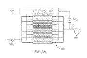
次に、図2A及び図2Bを参照すると、2つのブロック回路図が、図1Aのシステムにおける本発明に係るシャットダウン動作で遂行される、アノード流路及びカソード流路の相互作用に関する2つの実施形態を示している。特に図2Aを参照すると、スタック200、導管130に関するアノードブリード弁150A及びカソード背圧弁150C(排気弁とも呼ばれる)の配置が示される。これら2つの弁は、漏れLが検出された際にシステム1のシャットダウン動作実行を支援するために用いられることが可能であり、背圧弁150Cはカソード反応物質をスタック200から排出するためにも用いられる。ウォームアップ時にスタック200からの排気の削減を援助するべく、触媒加熱するために、又は、スタック200の負荷同期(load-syncing)を促進する目的で電圧を抑制するために、スタック200のカソード230部位に残留する水素を希釈しようとして酸素を導入する目的で、追加的な弁(例えば、図示しないバイパス弁)を用いることが可能である。他の弁(例えば、図示しないバイパス弁)も、システム1の動作改善を促進するために設けられてもよい。
2A and 2B, two embodiments of two block circuit diagrams relating to the interaction of the anode flow path and the cathode flow path are performed in the shutdown operation according to the present invention in the system of FIG. 1A. Is shown. With particular reference to FIG. 2A, the arrangement of
検出された水素漏れに加え、共働するブリード弁150A及び背圧弁150Cが従う入力パラメータは、様々な温度条件、圧力条件、設定点条件を含んでもよい。これら及び他のパラメータ(例えば、制御装置160の機能を可能若しくは無効にするパラメータ)は、制御装置160によってシステム1の動作を変更させるために使用されてもよい。さらに、本明細書で記載される制御論理の大部分は、(総じて)弁150並びに(特に)アノードブリード弁150A及びカソード背圧弁150C及びその各ポンプ140の制御のためであるが、スタック200の通常動作の期間(normal periods)の制御を行うために、追加的な制御論理が適用されてもよいことが当業者によって理解されよう。燃料電池システム1は、さらに、その内部のガスの特性を計測する1以上のセンサSを含む。ある一形態において、当該センサSは、ガス(特にH2)を検出するセンサの形式であってもよく、スタック200と通信又は流体連通するように配置されて、内部の突然の大量の漏れの証拠(indicia)を示すために用いられるとともに、制御装置160と通信可能に配置されて、対応する漏れの信号を制御装置160に送出する。ある一形態において、そのようなセンサSは、スタック200からのボード外(overboard)への漏れを検出するために適切に近接した位置に配置されてもよい。これら及び他のセンサSが、制御装置160内に実現される演算的な制御手順によって作用する入力信号を供給可能なことが当業者によって了解されよう。例えば、幾つかのセンサSは、システム1のシャットダウン動作時又は通常動作のために、適切な電圧レベルが維持されているか否かを決定するために使用されてもよい。さらに他の特定の形態において、H2を検出するようなセンサSを必要としなくともよく、代わりにH2の漏れ又は濃度は、直接制御装置160によってモデル化してもよい。この漏れ又は濃度情報を得るためのそのようなモデル化に基づく方法の具体例は、「シャットダウン時及びスタートアップ時の燃料電池システムにおける水素濃度推定値を推定するためのオンライン方法」と題される米国特許第8195407号明細書、及び「燃料電池システムのためのアノードパージ及びドレイン弁手順」と題される米国特許出願公開第2013/0089797号明細書に見出されることが可能である。両者とも、本発明の譲受人の一方によって所有され、参照することによりその開示内容全体をここに盛り込むこととする。そのような構成では、センサの使用が圧力センサ及び温度センサの1つ又は複数に限定され、両者とも、スタック200の環境内及びその周囲においてより安定(robust)する可能性がある。
In addition to the detected hydrogen leakage, input parameters bleed valves 0.99 A and the back-pressure valve 0.99 C cooperating follow a variety of temperature conditions, pressure conditions may include a setpoint condition. These and other parameters (eg, parameters that enable or disable the function of the controller 160) may be used by the
次に、図1Bとともに図2A及び図2Bを参照すると、H2の流量で約5kW〜10kW以上に達する場合、本明細書において漏れLは大量であると考えられる。そのように、「大量」の漏れとして認定するために、アノード220部位の外側へ極めて高いレベルのH2の移送(例えば、アノードブリード弁150Aが車両サイズの典型的な燃料電池システム1で消費可能な約60kWのH2の通過を可能にするサイズとなる、所定のセル210における従来のカソード触媒加熱(CCH)に関連したレベル)となる必要は無いが、しかしながら、本発明のアプローチは、このような状況下でシャットダウンを遂行可能である。対照的に、同程度のサイズの燃料電池システム1でかなり一般的な漏れ(例えば、効率的観点からスタックの寿命切れ状況で規定(dictated)される)である約1kW未満のH2の流量(生成電流の低下において約5mA/cm2に対応する可能性あり)は、少量と考えられる。
Next, referring to FIG. 2A and FIG. 2B together with FIG. 1B, if the flow rate of H 2 reaches about 5 kW to 10 kW or more, the leakage L is considered to be large in this specification. As such, a very high level of H 2 transfer outside the
次に図3A及び図3Bを参照すると、燃料電池スタック200のシャットダウン事象(events)並びに圧力(図3A)及び電圧(図3B)に対するシャットダウンの影響のタイムチャートが示されている。特に、燃料電池スタック200の運転は、漏れLが検出される時刻T1まで続行される。漏れ検出の形態は、本発明にとって重要ではないが、ある1つの好適な形態は、アノード若しくはカソード流路に共働して配置されることが可能な水素ガスセンサS(例えば、図1Aに示される)を通じて行われてもよい。スタック200は、負荷300がかかっていること(例えば、車両ドライブトレインの電動モータ又は他の部品に結合されている)が仮定され、スタック200の各セル210内において、アノード220部位内の圧力は、カソード230部位の圧力より高くバイアスされている。一例として、仮想車両燃料電池スタック200の低圧力設定は、カソード230部位内を約110kPaとし、アノード220部位を約130kPaとする圧力設定でよく、ピーク電力時においてはそれぞれ約220kPa及び約240kPaとしてもよい。このような燃料電池スタック200の通常運転条件を背景に、本発明の方法及びシステムによるスタック200のシャットダウンは、大量の漏れを検出した際に、以下の3つの一般工程を含んでもよい。(1)時刻T1からT2に対応するアノード220部位の減圧、(2)他の経路を通じて供給されるか又は流出してカソード230部位に送られる(rerouted or bled)水素と酸素の化学反応による酸素の消費の結果、時刻T2からT3に対応する不活性流体(一般的には、窒素(N2))の相対的濃度の上昇、及び(3)時刻T3以降に対応するアノード220部位への不活性流体の導入である。これらの工程が、以下詳細に議論される。
Referring now to FIGS. 3A and 3B, a time chart of the shutdown effect on the
タイムチャートにおいてT0(スタック200が最大電力条件にて動作中)とT1(大量の突然の漏れLが検出される)との間の期間を参照すると、アノード部位圧力PAは、カソード部位圧力PCを超えている。時刻T1における(例えば1以上のセンサSによる)漏れLの検出に呼応して、制御装置160が、燃料源110からの第1反応物質(すなわち、H2等の形態である燃料)の供給を遮断することにより第1工程の動作を開始し、スタック200への第1反応物質の移送が終了となる。この間、アノード220部位の圧力制御は続行される。その後すぐに(時刻T1〜時刻T2に渡る期間で明示されるように)、最初はカソード230部位の圧力よりも速く、アノード220部位の圧力が低減し始める。上述の通り、アノード圧力は、好ましくはH2注入器又は好適に構成されたポンプ140によって制御される。スタック200からの電力の取得(例えば、約0.1A/cm2(約10kWと等価))は低減されるべきであり、好ましくはスタック200の負荷の要求電力の値と同等とされる。電力取得量に対応する信号を伝送するセンサSが設けられ、制御装置160と通信可能とし、このような同等さを維持するよう補助してもよい。本開示の他の箇所で記載されるように、このような負荷は、補助機器(本明細書で議論される様々な寄生負荷及び他の負荷)の形態をとってもよい。負荷(例えば走行モータ等)の要求が低い場合、システム1の寄生構成要素、例えばコンプレッサ、ポンプ、バッテリ、抵抗加熱器、空調装置他のいずれか1つ又は複数が、依然として生成される過剰な電力を消費するために用いられてもよい。一形態において、カソード230部位の化学量(stoichiometry)がより高いスタック200を動作させ、排気(emission)を低く保つことも有益である。これは、アノードからカソード(anode-to-cathode)への漏れがカソード230部位側の出口近くで起き、H2を消費する活性領域が限られている場合、特に有益である。カソード230部位の高流量は、コンプレッサ力(power)を増加させ、アノード220部位のH2消費を速める結果となる。スタック200の冷却媒体の流量(適切に装備されたポンプ、導管、弁及び制御回路によってもたらされることが可能(いずれも図示せず))は、最大流量まで増加させるべきである。これは、局所的に発生する如何なる反応ホットスポットも冷却すること、及びH2消費を促進するために利用可能な上述された他の寄生負荷を具備すること、に役立つ。
Referring to the period between the time chart T 0 (the
上述した3つの一般工程のうちの第1工程の一部において、アノード220部位を減圧するために、アノードブリード弁150Aが開かれる。図2Aに示されるように、導管及び関連する機器のサイズは、H2の流れにおける最も抵抗の少ない流路が、漏れの場所Lを通過する流路よりブリード弁150Aを通過する流路の可能性があるように設定される。さらに(少なくとも図2Aに示される実施形態において)、アノードブリード弁150Aから放出されるH2は、個々のセル210のカソード230部位に供給するために用いられる入口マニフォールド若しくは導管130の一部であるヘッダにおいて混合し、それによりそのH2は全てのセル210において相対的に等しく分配され、上述したCCHと同様な方法で消費される。カソード230部位の弁(背圧弁150C及び図示しない如何なるバイパス弁をも含む)は、アノード220部位の圧力PAを制御するためにも操作可能であり、カソード230部位の圧力PCに比してアノード220部位の圧力PAに小さいバイアス(例えば、約5〜10kPa)をかけて維持した状態で、その圧力低減が可能となる。この工程は、アノード220部位の圧力PAが大気圧(すなわち、約14.7lb/in2又は100kPa)に近づいた際に終了してもよい。この工程の間、故障(compromised)セルの電圧VLEAKが急激に低下するが、平均スタック電圧VAVEは、比較的影響を受けないままである。
In some of the first step of the above-described three general steps, the
時刻T2に開始される第2工程に関し、H2及びO2の触媒反応により、カソード230部位内で周囲空気の供給で存在する窒素の相対的濃度が増加する。この第2工程の間、次の工程で議論される方法で有益な不活性流体、すなわちN2の局所的濃度増加がなされる。この第2工程の間、アノード220部位及びカソード230部位を互いに隔離するために、アノードブリード弁150Aを閉じることが重要である。さらに、スタック200の端子電圧が、H2の大部分が消費されたことを示すゼロ又は略ゼロに低下するまで、スタック200の負荷を維持し反応物質(H2及びO2の両者)を消費し続けることが重要である。このように、H2が消費されるにつれて、スタック200から出力される電力が徐々にゼロ又は略ゼロまで低下する。これは、電力が突然開放される上述の「急停止」の修復アプローチと対照的である。可能な限り多くのO2がカソード230部位で減少することを確実にするために、背圧弁150Cが閉じられる。これは、通常のシャットダウン中に生じるO2減少に類似したやり方によって、カソード230部位の圧力を上げるためにさらに役立つ。加えて、平均スタック電圧VAVEが低下し始めるが、漏れが生じている(又は故障)セルの電圧VLEAKの低下にまだ追いつかない。この工程は、平均スタック電圧VAVEが所定の閾値を下回った際に完了してもよい。一形態において、この閾値は、スタック200が如何なる寄生負荷も駆動できなくなる電圧レベルである。他の形態において、この工程は、アノード部位圧力PAが大気圧を下回った際に完了してもよい。一形態において、背圧弁150Cは、上述したアノード部位圧力PAの低い圧力バイアスを維持する方法として、カソード部位圧力PCの圧力を低減させるために若干開位置になるよう操作されてもよい。そのような操作は、消費によりアノード220部位の圧力PAが適切に低いレベルへ低減するまでなされてもよい(例えば大気圧以下)。図3Bの電圧記録で了解可能なように、漏れが生じている/故障セルの電圧VLEAKが負の値となる期間が存在する可能性がある。これは、漏れが生じている/故障セルの炭素腐食をもたらすことが予想されるが、発明者は、漏れLが進行したためセルがいずれにせよ交換される必要があるという点においてこのことは問題にはならないと主張する。上述のように、もしETSからの負荷が得られなければ、システム1は、制御装置160を通じて、直ぐに利用可能な形態の寄生負荷(例えば上述のポンプ、コンプレッサ、又は他の搭載機器)の1つ又は複数を使用するように動作してもよい。
It relates second step is initiated at time T 2, by catalytic reaction of H 2 and O 2, the relative concentration of nitrogen present in the supply of ambient air at the
第3工程において、アノード220部位に不活性流体(N2)を再び満たすこと又は増加させることが時刻T3から始まる。この工程において、アノード部位圧力PAが大気圧以下になった際に、ポンプ140又は関係するコンプレッサの動作が停止され、それにより反応物質がスタック200へ移送されなくなる。この場合、ブリード弁150Aが開かれ、背圧弁150Cが閉じられたまま、N2リッチの空気がカソード230部位からアノード220部位に導管130の一部であるヘッダ、及びブリード弁150Aを介して移送され、アノード220部位に不活性流体(N2)を再び満たすか、又は増加させる。この間、スタック電圧放電抵抗600を連結し、スタック200内に残留する空気及びH2を消費する。アノード220部位を不活性流体(N2)で満たすことにより、局所的な反応によるスタック200内の発熱を防止することが重要である。他の形態において、アノード圧力PAが大気圧以下になった際に、コンプレッサ(ある実施形態では、図1Aのポンプ140のように作動する)が停止されブリード弁150Aが開かれることにより、N2リッチの空気をアノード220に押し出し、スタック200内に残留するH2を希釈する。
In the third step, refilling or increasing the inert fluid (N 2 ) at the
本明細書で用いられる「好ましくは」「一般的に(又は略)」及び「通常(又は典型的)」のような文言は、本発明の特許請求の範囲を限定するためにも、ある特徴が該特許請求の範囲の構造又は機能に対して決定的、必須又は重要であるということを含意するためにも使用されないことに留意されたい。むしろ、これらの文言は、本発明のある特定の実施形態において利用可能か又は利用可能でない、代替的又は追加的な特徴を強調するために単に意図されているにすぎない。 As used herein, terms such as “preferably”, “generally (or abbreviated)” and “ordinary (or typical)” also refer to certain features to limit the scope of the claims of the present invention. Is not used to imply that is critical, essential or important to the structure or function of the claims. Rather, these terms are merely intended to highlight alternative or additional features that may or may not be available in certain embodiments of the invention.
本発明を記載し規定するために、本明細書で用いられる文言「略(又は実質的に)」、「約」及びその類義語は、何らかの量的な比較、値、測定及び他の表現に起因する可能性のある、内在する不確かさの度合いを示すことに留意されたい。本明細書で用いられる文言「略」は、問題となる主題の基本的な機能に変化をもたらさずに、量的な表現が記載された内容から変化する可能性があるという度合いを示すことにも留意されたい。 To describe and define the present invention, the terms “abbreviated (or substantially)”, “about” and similar terms used herein are derived from any quantitative comparison, value, measurement and other expressions. Note that it indicates the degree of inherent uncertainty that may be. The term “abbreviation” as used herein refers to the degree to which a quantitative expression may change from what is described without causing a change in the basic function of the subject matter in question. Please also note.
具体的な実施形態を参照して本発明を詳細に説明することにより、添付の請求項の範囲で規定される本発明の範囲から逸脱することなく、その改変及び変形が可能であることは、明白である。特に、本発明の範囲は、記載された好ましい態様及び例示された実施形態に必ずしも限定されず、添付の請求項によって規定される。 Having described the invention in detail with reference to specific embodiments, modifications and variations can be made without departing from the scope of the invention as defined in the appended claims. It is obvious. In particular, the scope of the invention is not necessarily limited to the preferred aspects and illustrated embodiments described, but is defined by the appended claims.
1…燃料電池システム 100…反応物質移送システム
110…燃料源 120…酸素源
140…ポンプ 150…弁
160…制御装置 200…燃料電池スタック
210…燃料電池(セル) 220…アノード
230…カソード 300…負荷
400…ドライブトレイン 500…動力装置
DESCRIPTION OF SYMBOLS 1 ... Fuel cell system 100 ... Reactant transfer system 110 ...
Claims (10)
アノード及び第1反応物質を含む第1源に結合され且つ第1弁が配置されるアノード流路を規定する第1部位と、カソード及び第2反応物質を含む第2源に結合され且つ第2弁が配置されるカソード流路を規定する第2部位と、前記第1部位と前記第2部位との間に位置するプロトン透過性電解質と、をそれぞれ備える複数の燃料電池を含む前記燃料電池スタック内の漏れを検出する工程と、
前記漏れの検出に呼応して、前記第1反応物質の前記アノードへの供給を遮断することにより、前記第1部位内の圧力を低減させる工程と、
端子電圧及び第1部位圧力の少なくとも一方が各所定レベルを下回るまで前記第2部位内の前記第1反応物質及び前記第2反応物質の少なくとも一部の消費を促進させるために、前記第1弁及び第2弁の少なくとも一方を操作することにより前記カソード流路内の不活性流体の濃度を増加させる工程と、
前記第2部位から前記第1部位に前記不活性流体の少なくとも一部を移送する工程と、を含み、
前記第1部位内の圧力を低減させる前記工程は、前記アノード流路内の前記第1弁と前記カソード流路内の前記第2弁との少なくとも一方を操作することを含むことを特徴とする動作中に燃料電池スタックをシャットダウンする方法。 A method of shutting down a fuel cell stack during operation,
A first portion coupled to a first source including an anode and a first reactant and defining an anode flow path in which a first valve is disposed, and a second portion coupled to a second source including a cathode and a second reactant. The fuel cell stack including a plurality of fuel cells each including a second portion that defines a cathode flow path in which a valve is disposed, and a proton-permeable electrolyte positioned between the first portion and the second portion. Detecting leaks in the interior;
In response to detecting the leak, reducing the pressure in the first site by blocking the supply of the first reactant to the anode;
In order to promote consumption of at least a portion of the first reactant and the second reactant in the second site until at least one of a terminal voltage and a first site pressure is below each predetermined level, the first valve And increasing the concentration of the inert fluid in the cathode flow path by operating at least one of the second valve;
Transferring at least a portion of the inert fluid from the second site to the first site,
The step of reducing the pressure in the first part includes operating at least one of the first valve in the anode channel and the second valve in the cathode channel. How to shut down the fuel cell stack during operation.
前記第1弁はブリード弁であり、前記第2弁は背圧弁であり、前記第1弁を操作する前記工程は、前記ブリード弁を通過する前記第1反応物質の少なくとも一部が前記第2部位へ移送されるように、前記ブリード弁を開く工程を含み、前記第2弁を操作する前記工程は、前記第2部位に比して前記第1部位に圧力バイアスをかけて維持するために十分な量だけ前記背圧弁を閉じる工程を含むことを特徴とする動作中に燃料電池スタックをシャットダウンする方法。 The method of claim 1, wherein
The first valve is a bleed valve, the second valve is a back pressure valve, and the step of operating the first valve includes at least part of the first reactant passing through the bleed valve. Opening the bleed valve to be transferred to the site, the step of operating the second valve to maintain a pressure bias on the first site relative to the second site. A method of shutting down a fuel cell stack during operation, comprising closing the back pressure valve by a sufficient amount.
端子電圧の前記所定レベルは、約0ボルトであって、前記第1部位圧力の前記所定レベルは、略周囲雰囲気圧力であることを特徴とする動作中に燃料電池スタックをシャットダウンする方法。 The method according to claim 1 or 2, wherein
A method for shutting down a fuel cell stack during operation, wherein the predetermined level of terminal voltage is approximately 0 volts and the predetermined level of the first site pressure is approximately ambient pressure.
前記不活性流体の濃度を増加させる前記工程は、所定の状態が発生した際に実質的に終了し、前記所定の状態とは、前記第1部位圧力が周囲雰囲気圧力を下回るか、又は前記燃料電池スタックの電圧が寄生負荷を駆動するために必要となる値を下回るか、の少なくとも一方であることを特徴とする動作中に燃料電池スタックをシャットダウンする方法。 The method according to any one of claims 1 to 3,
The step of increasing the concentration of the inert fluid substantially ends when a predetermined condition occurs, wherein the predetermined condition is that the first site pressure is below ambient ambient pressure or the fuel A method of shutting down a fuel cell stack during operation, characterized in that the voltage of the cell stack is below or at least one of the values required to drive a parasitic load.
前記第1部位内の圧力を低減させる前記工程は、さらに、前記燃料電池スタックによって供給される電流を、スタック補助機器を動作させるのに必要な量に実質的に一致するレベルまで低下させる工程を含むことを特徴とする動作中に燃料電池スタックをシャットダウンする方法。 The method according to any one of claims 1 to 4,
The step of reducing the pressure in the first portion further comprises the step of reducing the current supplied by the fuel cell stack to a level that substantially matches the amount required to operate the stack auxiliary equipment. A method for shutting down a fuel cell stack during operation.
前記スタック内の漏れを検出する前記工程は、少なくとも1つのガス検出センサによって行われ、前記ガス検出センサは、前記燃料電池スタックと流体連通するように配置され、前記圧力を低減する前記工程、前記不活性流体の濃度を増加させる前記工程、及び前記不活性流体を移送する前記工程のうち少なくとも1つの工程が、少なくとも部分的に、前記ガス検出センサと通信する制御装置によって行われることを特徴とする動作中に燃料電池スタックをシャットダウンする方法。 The method according to any one of claims 1 to 5,
The step of detecting a leak in the stack is performed by at least one gas detection sensor, the gas detection sensor being disposed in fluid communication with the fuel cell stack, the step of reducing the pressure, At least one of the step of increasing the concentration of the inert fluid and the step of transferring the inert fluid is performed at least in part by a controller that communicates with the gas detection sensor. To shut down the fuel cell stack during operation.
前記スタック内の漏れを検出する前記工程、前記圧力を低減する前記工程、前記不活性流体の濃度を増加させる前記工程、及び前記不活性流体を移送する前記工程は、少なくとも部分的に、少なくとも1つの圧力センサ及び少なくとも1つの温度センサを通じて、前記燃料電池スタックと通信する制御装置によって行われ、且つガス検出センサからの入力無しに行われることを特徴とする動作中に燃料電池スタックをシャットダウンする方法。 The method according to any one of claims 1 to 6,
The step of detecting leaks in the stack, the step of reducing the pressure, the step of increasing the concentration of the inert fluid, and the step of transferring the inert fluid are at least partially at least 1 A method of shutting down a fuel cell stack during operation, performed by a controller in communication with the fuel cell stack through one pressure sensor and at least one temperature sensor, and without input from a gas detection sensor .
第1反応物質を含む第1源と、
第2反応物質を含む第2源と、
第1部位を前記第1源に流体的に結合するアノード流路と、
第2部位を前記第2源に流体的に結合するカソード流路と、
前記アノード流路及び前記カソード流路の少なくとも一方と流体的に共働する少なくとも1つの流量制御弁と、
前記燃料電池に電気的に結合され、前記燃料電池内に生成される電流が少なくとも部分的に消費可能である負荷と、
前記流量制御弁、前記燃料電池、及び前記負荷の少なくとも1つに結合され、漏れ状態の特定に呼応してシャットダウン命令を与える制御装置と、を含む燃料電池システムであって、
前記燃料電池は、前記第1部位と、前記第2部位と、前記第1部位と前記第2部位との間に位置するプロトン透過性電解質と、を含み、
前記制御装置は、
前記漏れ状態の証拠(indicia)を受領し、
前記少なくとも1つの流量制御弁を操作することにより、前記第1部位への前記第1反応物質の供給を遮断して前記第1部位内の圧力を低減させ、
前記少なくとも1つの流量制御弁又は他の流量制御弁を操作することにより、前記第2反応物質の消費を増加させ、当該増加した消費が前記カソード流路内に存在する不活性流体の濃度を増加させ、
前記アノード流路及び前記カソード流路の少なくとも一方を通じて、前記第2部位から前記第1部位に前記不活性流体の少なくとも一部を移送する、ことを特徴とする燃料電池システム。 A fuel cell;
A first source comprising a first reactant;
A second source comprising a second reactant,
An anode flow path that fluidly couples a first portion to the first source;
A cathode flow path that fluidly couples a second portion to the second source;
At least one flow control valve fluidly cooperating with at least one of the anode flow path and the cathode flow path;
A load electrically coupled to the fuel cell and capable of at least partially consuming current generated in the fuel cell;
A fuel cell system comprising: a control device coupled to at least one of the flow control valve, the fuel cell, and the load, and providing a shutdown command in response to specifying a leakage condition;
The fuel cell includes the first part, the second part, and a proton-permeable electrolyte positioned between the first part and the second part,
The controller is
Receiving indicia of the leak condition,
By operating the at least one flow control valve, the supply of the first reactant to the first part is cut off to reduce the pressure in the first part,
By operating the at least one flow control valve or other flow control valve, the consumption of the second reactant is increased, and the increased consumption increases the concentration of inert fluid present in the cathode flow path. Let
A fuel cell system, wherein at least part of the inert fluid is transferred from the second part to the first part through at least one of the anode channel and the cathode channel.
前記漏れ状態は、前記燃料電池と流体連通するように配置される少なくとも1つのセンサによって特定され、前記少なくとも1つのセンサは、圧力及び温度の少なくとも1つを検出することを特徴とする燃料電池システム。 The fuel cell system according to claim 8, wherein
The leak condition is identified by at least one sensor disposed in fluid communication with the fuel cell, the at least one sensor detecting at least one of pressure and temperature. .
複数の燃料電池と、アノード流路と、カソード流路と、を前記燃料電池スタック内に設ける工程と、
前記アノード流路内に配置される第1弁と、前記カソード流路内に配置される第2弁と、を設ける工程と、
前記燃料電池スタックに結合される制御装置を用いる工程と、を含み、
前記複数の燃料電池は、それぞれ、アノードと、第1反応物質を含む第1反応物質源に前記アノードを流体的に結合する前記アノード流路と、を含む第1部位と、
カソードと、第2反応物質を含む第2反応物質源に前記カソードを流体的に結合する前記カソード流路と、を含む第2部位と、
前記第1部位と前記第2部位との間に位置するプロトン透過性電解質と、を含み、
前記制御装置は、
前記反応物質の漏れの検出に対応する少なくとも1つの信号を受信する工程と、
前記第1部位内の圧力を低減させるために、前記第1弁と前記第2弁との少なくとも一方を操作することにより、前記第1反応物質の前記アノードへの供給を遮断する工程と、
前記第1反応物質及び前記第2反応物質の消費を促進させるために、前記第1弁及び前記第2弁の少なくとも一方を操作する工程と、
端子電圧及び第1部位圧力の少なくとも一方が各所定レベルを下回った後、前記第2部位から前記第1部位に不活性流体の少なくとも一部を移送する工程と、
を行うことを特徴とする、動作中の燃料電池スタック内の反応物質の漏れ検出時に、当該燃料電池スタックをシャットダウンする方法。 A method of shutting down a fuel cell stack upon detection of leakage of a reactant in the fuel cell stack during operation,
Providing a plurality of fuel cells, an anode channel, and a cathode channel in the fuel cell stack;
Providing a first valve disposed in the anode flow path and a second valve disposed in the cathode flow path;
Using a control device coupled to the fuel cell stack,
Each of the plurality of fuel cells includes a first portion including an anode and the anode flow path that fluidly couples the anode to a first reactant source that includes a first reactant;
A second portion comprising: a cathode; and the cathode flow path fluidly coupling the cathode to a second reactant source comprising a second reactant;
A proton permeable electrolyte located between the first part and the second part,
The controller is
Receiving at least one signal corresponding to detection of leakage of the reactant;
Shutting off the supply of the first reactant to the anode by operating at least one of the first valve and the second valve to reduce the pressure in the first site;
Operating at least one of the first valve and the second valve to promote consumption of the first reactant and the second reactant;
Transferring at least part of the inert fluid from the second part to the first part after at least one of the terminal voltage and the first part pressure is below each predetermined level;
A method for shutting down a fuel cell stack when detecting leakage of a reactant in the fuel cell stack during operation.
Applications Claiming Priority (2)
| Application Number | Priority Date | Filing Date | Title |
|---|---|---|---|
| US14/742,785 | 2015-06-18 | ||
| US14/742,785 US10439239B2 (en) | 2015-06-18 | 2015-06-18 | Shutdown method of fuel cell stack and fuel cell system therefor |
Publications (2)
| Publication Number | Publication Date |
|---|---|
| JP2017010927A JP2017010927A (en) | 2017-01-12 |
| JP6133473B2 true JP6133473B2 (en) | 2017-05-24 |
Family
ID=57467192
Family Applications (1)
| Application Number | Title | Priority Date | Filing Date |
|---|---|---|---|
| JP2016106938A Active JP6133473B2 (en) | 2015-06-18 | 2016-05-30 | Fuel cell stack shutdown method and fuel cell system therefor |
Country Status (3)
| Country | Link |
|---|---|
| US (1) | US10439239B2 (en) |
| JP (1) | JP6133473B2 (en) |
| DE (1) | DE102016110250B4 (en) |
Families Citing this family (6)
| Publication number | Priority date | Publication date | Assignee | Title |
|---|---|---|---|---|
| DE102016114103A1 (en) * | 2016-07-29 | 2018-02-01 | Proton Motor Fuel Cell Gmbh | Explosion-proof fuel cell system and method for decommissioning a fuel cell system |
| DE102018131160A1 (en) * | 2018-12-06 | 2020-06-10 | Bayerische Motoren Werke Aktiengesellschaft | Process for reducing carbon corrosion in a fuel cell stack and motor vehicle |
| KR102842969B1 (en) * | 2019-07-22 | 2025-08-06 | 현대자동차주식회사 | Appartus and method for controlling emergency driving for fuel cell vehicle |
| JP2021103644A (en) * | 2019-12-25 | 2021-07-15 | 富士電機株式会社 | Fuel cell system |
| DE102022203514A1 (en) * | 2022-04-07 | 2023-10-12 | Robert Bosch Gesellschaft mit beschränkter Haftung | Method for operating a fuel cell system |
| CN116989944B (en) * | 2023-09-27 | 2023-12-19 | 晋中学院 | Automatic detector for hydrogen fuel cell leakage |
Family Cites Families (13)
| Publication number | Priority date | Publication date | Assignee | Title |
|---|---|---|---|---|
| US6127057A (en) * | 1998-08-12 | 2000-10-03 | International Fuel Cells, Llc | Self-inerting fuel cell system |
| EP1487044A3 (en) * | 2003-04-17 | 2006-07-19 | Matsushita Electric Industrial Co., Ltd. | Method for detecting possible structural deficiencies of a polymer electrolyte fuel cell |
| WO2005041339A1 (en) * | 2003-10-23 | 2005-05-06 | Hydrogenics Corporation | A fuel cell power system having multiple fuel cell modules |
| US20050249987A1 (en) * | 2004-05-04 | 2005-11-10 | Angstrom Power Incorporated | Fault tolerant fuel cell systems |
| JP4761182B2 (en) | 2004-09-22 | 2011-08-31 | トヨタ自動車株式会社 | Fuel cell system |
| US7807307B2 (en) * | 2005-05-05 | 2010-10-05 | Motorola Mobility, Inc. | System and method for distributing fuel to multiple fuel cells |
| JP2006351241A (en) | 2005-06-13 | 2006-12-28 | Nissan Motor Co Ltd | Fuel cell system |
| US8071243B2 (en) * | 2005-12-02 | 2011-12-06 | Panasonic Corporation | Fuel cell system |
| US8057942B2 (en) * | 2007-10-18 | 2011-11-15 | GM Global Technology Operations LLC | Assisted stack anode purge at start-up of fuel cell system |
| US8195407B2 (en) | 2009-10-09 | 2012-06-05 | GM Global Technology Operations LLC | Online method to estimate hydrogen concentration estimation in fuel cell systems at shutdown and startup |
| US9105888B2 (en) | 2011-10-07 | 2015-08-11 | GM Global Technology Operations LLC | Anode purge and drain valve strategy for fuel cell system |
| DE102012018873A1 (en) * | 2012-09-25 | 2014-03-27 | Daimler Ag | Method for detecting a critical hydrogen concentration |
| US8956778B2 (en) * | 2012-10-25 | 2015-02-17 | GM Global Technology Operations LLC | Cathode flow split control and pressure control for a vehicle fuel cell power system |
-
2015
- 2015-06-18 US US14/742,785 patent/US10439239B2/en active Active
-
2016
- 2016-05-30 JP JP2016106938A patent/JP6133473B2/en active Active
- 2016-06-02 DE DE102016110250.4A patent/DE102016110250B4/en active Active
Also Published As
| Publication number | Publication date |
|---|---|
| DE102016110250A1 (en) | 2016-12-22 |
| JP2017010927A (en) | 2017-01-12 |
| DE102016110250B4 (en) | 2024-09-05 |
| US20160372767A1 (en) | 2016-12-22 |
| US10439239B2 (en) | 2019-10-08 |
Similar Documents
| Publication | Publication Date | Title |
|---|---|---|
| JP6133473B2 (en) | Fuel cell stack shutdown method and fuel cell system therefor | |
| US7972736B2 (en) | Fuel cell system with warming-up and method of operating the same | |
| JP5083587B2 (en) | Fuel cell system and temperature adjustment method thereof | |
| CN107004876B (en) | Method for disconnecting fuel cell stack and fuel cell system | |
| US20080254328A1 (en) | Closed Coolant Loop with Expansion Device for a Fuel Cell System | |
| JP4644064B2 (en) | Fuel cell system | |
| US20180351185A1 (en) | Method of controlling operation of fuel cell | |
| KR20140076699A (en) | THERMAL MANAGEMENT SYSTEM FOR FUEL CELL STACK and CONTROL METHOD FOR THE SAME | |
| US6703152B2 (en) | Method of operating phosphoric acid fuel cell | |
| CN104918818B (en) | The method of the shutoff operation of the adjustment of fuel battery power device | |
| CN102201584B (en) | Diagnosis concept for valve controlled coolant bypass paths | |
| KR101163464B1 (en) | Thermal management system for fuel cell vehicle maintaining electrical conductivity and heating capacity | |
| JP6258378B2 (en) | Control method of fuel cell system | |
| JP4426892B2 (en) | Fuel cell system | |
| US7678477B2 (en) | Method of operating a fuel cell stack | |
| JP6307536B2 (en) | Low temperature startup method for fuel cell system | |
| JP6335947B2 (en) | Stop control method for fuel cell system | |
| JP5721451B2 (en) | Fuel cell system and control method thereof | |
| JP2017147140A (en) | Operation method of fuel cell system | |
| JP2009004168A (en) | Fuel cell system | |
| JP5485930B2 (en) | Control method of fuel cell system | |
| JP2007305334A (en) | Fuel cell system | |
| JP2018181839A (en) | Fuel cell system | |
| JP2011014339A (en) | Fuel cell system, and method of controlling fuel cell system | |
| JP2006294498A (en) | Fuel cell system |
Legal Events
| Date | Code | Title | Description |
|---|---|---|---|
| TRDD | Decision of grant or rejection written | ||
| A01 | Written decision to grant a patent or to grant a registration (utility model) |
Free format text: JAPANESE INTERMEDIATE CODE: A01 Effective date: 20170321 |
|
| A61 | First payment of annual fees (during grant procedure) |
Free format text: JAPANESE INTERMEDIATE CODE: A61 Effective date: 20170419 |
|
| R150 | Certificate of patent or registration of utility model |
Ref document number: 6133473 Country of ref document: JP Free format text: JAPANESE INTERMEDIATE CODE: R150 |
|
| R250 | Receipt of annual fees |
Free format text: JAPANESE INTERMEDIATE CODE: R250 |
|
| R250 | Receipt of annual fees |
Free format text: JAPANESE INTERMEDIATE CODE: R250 |
|
| R250 | Receipt of annual fees |
Free format text: JAPANESE INTERMEDIATE CODE: R250 |
|
| R250 | Receipt of annual fees |
Free format text: JAPANESE INTERMEDIATE CODE: R250 |
|
| R250 | Receipt of annual fees |
Free format text: JAPANESE INTERMEDIATE CODE: R250 |
|
| R250 | Receipt of annual fees |
Free format text: JAPANESE INTERMEDIATE CODE: R250 |