JP6132284B2 - Spacer - Google Patents
Spacer Download PDFInfo
- Publication number
- JP6132284B2 JP6132284B2 JP2013113692A JP2013113692A JP6132284B2 JP 6132284 B2 JP6132284 B2 JP 6132284B2 JP 2013113692 A JP2013113692 A JP 2013113692A JP 2013113692 A JP2013113692 A JP 2013113692A JP 6132284 B2 JP6132284 B2 JP 6132284B2
- Authority
- JP
- Japan
- Prior art keywords
- frame
- groove
- battery module
- end edge
- spacer
- Prior art date
- Legal status (The legal status is an assumption and is not a legal conclusion. Google has not performed a legal analysis and makes no representation as to the accuracy of the status listed.)
- Active
Links
- 125000006850 spacer group Chemical group 0.000 title claims description 57
- 230000004308 accommodation Effects 0.000 description 6
- 238000005192 partition Methods 0.000 description 6
- 230000037431 insertion Effects 0.000 description 4
- 238000003780 insertion Methods 0.000 description 4
- 238000004519 manufacturing process Methods 0.000 description 4
- WABPQHHGFIMREM-UHFFFAOYSA-N lead(0) Chemical compound [Pb] WABPQHHGFIMREM-UHFFFAOYSA-N 0.000 description 3
- 230000015572 biosynthetic process Effects 0.000 description 2
- 230000002093 peripheral effect Effects 0.000 description 2
- 238000006073 displacement reaction Methods 0.000 description 1
- 230000005611 electricity Effects 0.000 description 1
- 238000000605 extraction Methods 0.000 description 1
- 229910052739 hydrogen Inorganic materials 0.000 description 1
- 239000001257 hydrogen Substances 0.000 description 1
- 230000000149 penetrating effect Effects 0.000 description 1
Images


Classifications
-
- H—ELECTRICITY
- H01—ELECTRIC ELEMENTS
- H01M—PROCESSES OR MEANS, e.g. BATTERIES, FOR THE DIRECT CONVERSION OF CHEMICAL ENERGY INTO ELECTRICAL ENERGY
- H01M50/00—Constructional details or processes of manufacture of the non-active parts of electrochemical cells other than fuel cells, e.g. hybrid cells
- H01M50/20—Mountings; Secondary casings or frames; Racks, modules or packs; Suspension devices; Shock absorbers; Transport or carrying devices; Holders
- H01M50/204—Racks, modules or packs for multiple batteries or multiple cells
- H01M50/207—Racks, modules or packs for multiple batteries or multiple cells characterised by their shape
- H01M50/213—Racks, modules or packs for multiple batteries or multiple cells characterised by their shape adapted for cells having curved cross-section, e.g. round or elliptic
-
- H—ELECTRICITY
- H01—ELECTRIC ELEMENTS
- H01M—PROCESSES OR MEANS, e.g. BATTERIES, FOR THE DIRECT CONVERSION OF CHEMICAL ENERGY INTO ELECTRICAL ENERGY
- H01M50/00—Constructional details or processes of manufacture of the non-active parts of electrochemical cells other than fuel cells, e.g. hybrid cells
- H01M50/20—Mountings; Secondary casings or frames; Racks, modules or packs; Suspension devices; Shock absorbers; Transport or carrying devices; Holders
- H01M50/289—Mountings; Secondary casings or frames; Racks, modules or packs; Suspension devices; Shock absorbers; Transport or carrying devices; Holders characterised by spacing elements or positioning means within frames, racks or packs
- H01M50/291—Mountings; Secondary casings or frames; Racks, modules or packs; Suspension devices; Shock absorbers; Transport or carrying devices; Holders characterised by spacing elements or positioning means within frames, racks or packs characterised by their shape
-
- H—ELECTRICITY
- H01—ELECTRIC ELEMENTS
- H01M—PROCESSES OR MEANS, e.g. BATTERIES, FOR THE DIRECT CONVERSION OF CHEMICAL ENERGY INTO ELECTRICAL ENERGY
- H01M2220/00—Batteries for particular applications
- H01M2220/10—Batteries in stationary systems, e.g. emergency power source in plant
-
- Y—GENERAL TAGGING OF NEW TECHNOLOGICAL DEVELOPMENTS; GENERAL TAGGING OF CROSS-SECTIONAL TECHNOLOGIES SPANNING OVER SEVERAL SECTIONS OF THE IPC; TECHNICAL SUBJECTS COVERED BY FORMER USPC CROSS-REFERENCE ART COLLECTIONS [XRACs] AND DIGESTS
- Y02—TECHNOLOGIES OR APPLICATIONS FOR MITIGATION OR ADAPTATION AGAINST CLIMATE CHANGE
- Y02E—REDUCTION OF GREENHOUSE GAS [GHG] EMISSIONS, RELATED TO ENERGY GENERATION, TRANSMISSION OR DISTRIBUTION
- Y02E60/00—Enabling technologies; Technologies with a potential or indirect contribution to GHG emissions mitigation
- Y02E60/10—Energy storage using batteries
Description
本発明は、スペーサに関し、詳しくは、複数のモジュールを積み重ねて構成される装置における各モジュール間に配置されるスペーサに関する。 The present invention relates to a spacer, and more particularly to a spacer disposed between modules in an apparatus configured by stacking a plurality of modules.
電気機器の内部には、種々の装置が組み込まれている。通常、これらの装置は、複数のモジュールが互いに積み重ねられて構成され、電気機器内に収容されている。
上記したようなモジュールは、単純に積み重ねたのでは安定性に欠けるので、一般的に、各モジュールの間にはスペーサが配置される。
Various devices are incorporated in the electric equipment. Usually, these devices are configured by stacking a plurality of modules on each other, and are accommodated in an electric device.
Since the modules described above lack stability when simply stacked, generally, a spacer is disposed between the modules.
ここで、電気機器に搭載される装置としては、例えば、バックアップ電源に使用される電池パック装置がある。この電池パック装置は、多数の汎用電池が並列又は直列に接続され所定の電圧及び容量を出力可能とした電池モジュールが、用途に合わせて複数個組み合わされることにより形成されている。この電池モジュールにおいて各汎用電池は、ケースに収容される、又は、一対のフレームの間に挟持されるような態様で固定されている。このような電池モジュールは、例えば、スペーサを介して積層され、電池パック装置に形成される(例えば、特許文献1参照)。 Here, as a device mounted on an electric device, for example, there is a battery pack device used for a backup power source. This battery pack device is formed by combining a plurality of battery modules that can output a predetermined voltage and capacity by connecting a large number of general-purpose batteries in parallel or in series. In this battery module, each general-purpose battery is fixed in such a manner that it is accommodated in a case or sandwiched between a pair of frames. Such a battery module is laminated | stacked through a spacer, for example, and is formed in a battery pack apparatus (for example, refer patent document 1).
ところで、特許文献1の電池パック装置の場合、ケースとケースの間のスペーサは、それぞれ連結部材にねじ止めされている。この場合、部品点数が多く、ねじ止めにより組立工数も増えるので、生産効率が低い。
また、一対のフレームを用いる電池モジュールの場合、フレームにおけるスペーサと接する部分の形状が、一方の側のフレームと他方の側のフレームとで異なるものがある。この場合、それぞれのフレームに対応した形状のスペーサを準備しなければならず、部品の種類が増え、製造コストの増加を招く。
By the way, in the case of the battery pack apparatus of patent document 1, the spacer between cases is screwed to the connection member, respectively. In this case, the number of parts is large and the number of assembly steps is increased by screwing, so that the production efficiency is low.
In addition, in the case of a battery module using a pair of frames, the shape of the portion in contact with the spacer in the frame differs between the frame on one side and the frame on the other side. In this case, spacers having shapes corresponding to the respective frames must be prepared, and the types of parts increase, resulting in an increase in manufacturing cost.
本発明は、上記の事情に基づいてなされたものであり、その目的とするところは、電池パック装置の製造において、部品の点数及び種類の低減が図れ、且つ、組み立て工数の削減も図れるスペーサを提供することにある。 The present invention has been made based on the above circumstances, and the object of the present invention is to provide a spacer that can reduce the number and types of parts and can reduce the number of assembly steps in the manufacture of a battery pack device. It is to provide.
上記目的を達成するために、本発明によれば、それぞれ板状をなす第1フレーム及び第2フレームと、前記第1フレームの板面及び前記第2フレームの板面の間に配設された複数の電池とを備えた電池モジュールを複数個重ねる際に、各電池モジュールの間に配設されるスペーサにおいて、角棒状をなし、その上面に設けられた上溝部と、その下面に設けられた下溝部とを備え、前記上溝部は、上側に位置する前記電池モジュールの第1フレームの下端縁を嵌合可能な形状の第1上溝と、上側に位置する前記電池モジュールの第2フレームの下端縁を嵌合可能な形状の第2上溝とを含み、前記下溝部は、下側に位置する前記電池モジュールの第1フレームの上端縁を嵌合可能な形状の第1下溝と、下側に位置する前記電池モジュールの第2フレームの上端縁を嵌合可能な形状の第2下溝とを含んでいることを特徴とするスペーサが提供される。 In order to achieve the above object, according to the present invention, the first frame and the second frame each having a plate shape are disposed between the plate surface of the first frame and the plate surface of the second frame. When stacking a plurality of battery modules each having a plurality of batteries, the spacer disposed between the battery modules has a square bar shape, an upper groove provided on the upper surface thereof, and provided on the lower surface thereof. A lower groove portion, and the upper groove portion has a first upper groove having a shape capable of fitting a lower end edge of the first frame of the battery module positioned on the upper side, and a lower end of the second frame of the battery module positioned on the upper side. A second upper groove having a shape capable of fitting an edge, and the lower groove portion includes a first lower groove having a shape capable of fitting an upper end edge of the first frame of the battery module located on the lower side, and a lower side. The second module of the battery module located Spacers are provided, characterized in that the upper edge of the over arm includes a second lower groove Metropolitan of shape to be fitted.
本発明のスペーサは、一つの部材の中に第1上溝、第2上溝、第1下溝及び第2下溝を備えている。本発明のスペーサの具体的な使い方としては、まず、同形状の本発明のスペーサを2本準備する。そして、一本のスペーサにおいては、第1フレームの下端縁を第1上溝に嵌合させ、第1フレームの上端縁を第1下溝に嵌合させる。もう一本のスペーサにおいては、第2フレームの下端縁を第2上溝に嵌合させ、第2フレームの上端縁を第2下溝に嵌合させる。このように、本発明のスペーサは、一種類のスペーサで、第1フレーム及び第2フレームの両方に対応が可能であり、部品点数を少なくすることができる。
また、本発明のスペーサは、第1フレーム及び第2フレームの各端縁を嵌合可能なので、個々に連結部材を介してねじ止めする必要がなく、組立工数を少なくすることができる。
The spacer of the present invention includes a first upper groove, a second upper groove, a first lower groove, and a second lower groove in one member. As a specific usage of the spacer of the present invention, first, two spacers of the present invention having the same shape are prepared. In one spacer, the lower end edge of the first frame is fitted into the first upper groove, and the upper end edge of the first frame is fitted into the first lower groove. In the other spacer, the lower end edge of the second frame is fitted into the second upper groove, and the upper end edge of the second frame is fitted into the second lower groove. As described above, the spacer according to the present invention is a single type of spacer and can be applied to both the first frame and the second frame, and the number of parts can be reduced.
Moreover, since the spacer of this invention can fit each edge of a 1st frame and a 2nd frame, it is not necessary to screw together via a connection member separately, and can reduce an assembly man-hour.
また、前記電池モジュールは、設置されるべき位置への位置決めに用いられる位置決め用凸部を有しており、前記第1上溝、前記第2上溝、前記第1下溝及び前記第2下溝における前記位置決め用凸部に対応する部分には、前記位置決め用凸部を受入可能な受入凹部が設けられている態様とすることが好ましい。 In addition, the battery module has a positioning convex portion used for positioning to a position to be installed, and the positioning in the first upper groove, the second upper groove, the first lower groove, and the second lower groove. It is preferable that the portion corresponding to the convex portion is provided with a receiving concave portion that can receive the positioning convex portion.
この態様のスペーサによれば、電池モジュールに位置決め用凸部が形成されていても、スペーサの第1上溝、第2上溝、第1下溝及び第2下溝における前記位置決め用凸部に対応する部分には、この位置決め用凸部を受入可能な受入凹部が設けられているので、かかる位置決め用凸部が上溝又は下溝の溝底と局部的にぶつかりあうことは抑制され、電池モジュールを安定的に積み重ねることができ電池パック装置の組立が容易となる。 According to the spacer of this aspect, even if the positioning convex portion is formed on the battery module, the portion corresponding to the positioning convex portion in the first upper groove, the second upper groove, the first lower groove, and the second lower groove of the spacer is provided. Since the receiving concave portion that can receive the positioning convex portion is provided, the positioning convex portion is prevented from colliding locally with the groove bottom of the upper groove or the lower groove, and the battery modules are stably stacked. As a result, the battery pack device can be easily assembled.
本発明によれば、電池パック装置の製造において、部品の点数及び種類の低減が図れ、且つ、組み立て工数の削減も図れるスペーサを提供することができる。 ADVANTAGE OF THE INVENTION According to this invention, in manufacture of a battery pack apparatus, the spacer which can aim at reduction of the number of parts and a kind and can also aim at reduction of an assembly man-hour can be provided.
以下、本発明に係るスペーサ2を適用した電池パック装置4を、図面を参照して説明する。
Hereinafter, a
図1に示したように、電池パック装置4は、2個の電池モジュール6,6が、角棒状のスペーサ2,2を介して積み重ねられて形成されている。なお、角棒状とは、横断面の形状が矩形状をなす長尺の棒状の形態をいう。
As shown in FIG. 1, the
この電池パック装置4は、電気機器内の収容スペースに収容される。通常、収容スペースは、所定面積の床面と、この床面の所定位置に設けられた支柱と、この支柱に取り付けられた押さえ板を含んでいる。そして、電池パック装置4は、収容スペースの床面に載置され、押さえ板により上から押さえられて固定されている。
The
次いで、電池モジュール6の形態について以下に説明する。
電池モジュール6は、図2に示すように、複数の組電池8が第1フレーム10及び第2フレーム12の間に並べられ、これら第1フレーム10及び第2フレーム12に挟持されることにより形成されている。
Next, the form of the
As shown in FIG. 2, the
組電池8は、汎用のAAサイズのニッケル水素二次電池(以下、単位電池という)が2個一組で並列に並べられ外装フィルムにより包み込まれることにより一体化されてなる。これら単位電池は、互いに正極端子側と負極端子側とが逆となるように並べられており、図示しないリードにより、一方の単位電池の負極端子と他方の単位電池の正極端子とが電気的に直列に接続されている。そして、一方の単位電池の正極端子及び他方の単位電池の負極端子は外装フィルムから露出している。このような組電池8は、18個準備され、互いの胴部が接するように並べられて組電池8の集合体に形成されている。このとき、各組電池は、図2から明らかなように、矢印A方向に傾いた状態で並べられている。そして、これら組電池8は、第1フレーム10及び第2フレーム12により挟持され固定されている。
The assembled
第1フレーム10は、図2において左側に位置しており、略長方形状をなす板状体である。この第1フレーム10には、図2から明らかなように、組電池8側の内面14に断面が略三角形状の押さえ突起16が複数設けられている。この押さえ突起16は、組電池8と組電池8との間の所定位置に位置付けられ、組電池8と接する部分が組電池8の外周縁の一部に沿う形状をなしており、これら組電池8が電池モジュール6の上下方向にずれることを抑える働きをなしている。更に、図2から明らかなように、第1フレーム10の長手方向の両端近傍には、端部ストッパ18が形成されている。この端部ストッパ18は、組電池8の胴部の外周縁に合致した形状をなした枠であり、最端部に位置する組電池8が電池モジュール6の前後方向にずれることを抑える働きをなしている。
The
ついで、第2フレーム12は、図2において右側に位置しており、略平行四辺形状をなす板状体である。この第2フレーム12にも、第1フレーム10と同様に、押さえ突起16及び端部ストッパ18が設けられている。この第2フレーム12の押さえ突起16は、第1フレーム10の押さえ突起16と同形状をなしており、第1フレーム10の押さえ突起16に対向する位置に位置付けられている。また、第2フレーム12の端部ストッパ18も、第1フレーム10の端部ストッパ18と同形状をなしており、第1フレーム10の端部ストッパ18に対向する位置に位置付けられている。
Next, the
上記したような第1フレーム10及び第2フレーム12は、対向配置されることにより、お互いの押さえ突起16及び端部ストッパ18が相対する位置に位置付けられ、これにより、第1フレーム10の押さえ突起16及び端部ストッパ18と、第2フレーム12の押さえ突起16及び端部ストッパ18とは、協働して組電池8の位置決めを行う。
The
上記したように組電池8が所定位置に位置決めされた第1フレーム10及び第2フレーム12は、連結具20により連結されている。この連結具20は、長手方向に延びる中心貫通孔を有する中空の円筒部材22と、この中心貫通孔に挿通されたボルト24と、このボルトに螺合されたナット26とからなる。この円筒部材22は、上記した組電池8の長手方向の長さと略同じ長さであり、第1フレーム10及び第2フレーム12の所定位置に設けられたボルト挿通孔に対応する位置に配置される。上記したボルト24は、第2フレーム12側のボルト挿通孔側から、連結具20の中心貫通孔を介して第1フレーム10側の貫通孔に挿通される。そして、第1フレーム10側のボルト挿通孔から突出したボルト24の先端にはナット26が螺合されている。これにより、第1フレーム10及び第2フレーム12が互いに近付く方向に付勢され各組電池8が挟持されて電池モジュール6が形成される。
As described above, the
ここで、第1フレーム10及び第2フレーム12の間に挟持され、所定位置に配置されている各組電池8は、第1フレーム10又は第2フレーム12に設けられたフレームリード(図示せず)により電気的に直列に接続されている。また、第2フレーム12には、図2に示すようにコネクタ用切欠28が設けられている。このコネクタ用切欠28の部分の内部に雌コネクタ(図示せず)が配設されており、この雌コネクタには上記したフレームリード(図示せず)が電気的に接続されている。そして、この雌コネクタには、雄コネクタ(図示せず)が差し込まれ、コネクタ用切欠28からは雄コネクタに接続されたリード線(図示せず)が引き出される。電池モジュール6においては、この雄コネクタ及びリード線を介して電気の入出力が行われる。
Here, each assembled
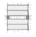
電池モジュール6は、上記したように、一方の側部に第1フレーム10が、他方の側部に第2フレーム12がそれぞれ位置付けられている。そして、この電池モジュール6を側面視した際、組電池8の集合体は、これら第1フレーム10及び第2フレーム12に隠れている(図3、図4参照)。つまり、これら第1フレーム10及び第2フレーム12は、組電池8の集合体よりも突出している。詳しくは、図5の断面図に表されているように、組電池8の断面において、胴部30の上端を胴部上端32、胴部30の下端を胴部下端34とした場合に、第1フレーム10及び第2フレーム12の上端縁36,38は胴部上端32よりも上方へ僅かに突出し、第1フレーム10及び第2フレーム12の下端縁40,42は胴部下端34よりも下方へ僅かに突出している。より詳しくは、第1フレーム10は、その上端縁(以下、第1上端縁という)36が組電池8の胴部上端32よりも上側に突出し、その下端縁(以下、第1下端縁という)40が組電池8の胴部下端34よりも下側に突出している。また、第2フレーム12は、その上端縁(以下、第2上端縁という)38が組電池8の胴部上端32よりも上側に突出し、その下端縁(以下、第2下端縁という)42が組電池8の胴部下端34よりも下側に突出している。
As described above, the
ここで、第1上端縁36及び第2上端縁38は、図3、図4から明らかなように、それぞれ、参照符号36a,36b,36c,36d,38a,38b,38c,38dで示された凹部を備えている。これら凹部は、収容スペース内の押さえ板に設けられた凸部を避けるために設けられている。
Here, as apparent from FIGS. 3 and 4, the first
また、第1下端縁40及び第2下端縁42は、図3、図4から明らかなように、それぞれ、参照符号40a,40b,40c,40d,42a,42b,42c,42dで示された位置決め用凸部を備えている。これら位置決め用凸部40a,40b,40c,40d,42a,42b,42c,42dは、収容スペースの床面の所定位置に設けられた凹部に嵌合され、最下部の電池モジュール6の位置決め、つまり、電池パック装置4の位置決めに利用される。
The first
通常、上記した凹部36a,36b,36c,36d,38a,38b,38c,38d、及び、位置決め用凸部40a,40b,40c,40d,42a,42b,42c,42dは、第1上端縁36、第1下端縁40、第2上端縁38及び第2下端縁42によって、形成されている位置や大きさが異なる。このため、電池モジュール6を直接積み重ねると、互いに当接するフレームの上端縁と下端縁とは局部的にぶつかりあってしまい、安定的に積み重ねることは困難である。このため、電池モジュール6と電池モジュール6との間にはスペーサ2が配置されている。
Usually, the
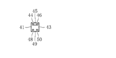
スペーサ2は、図2に示すように、横断面が矩形状の長尺の角棒であり、長手方向に沿って延びる凹溝が上側に2本、下側に2本の合計4本設けられている。詳しくは、スペーサ2は、図6に示す端面図から明らかなように、図6中左側且つ上側に位置付けられた第1上溝44と、図6中右側且つ上側に位置付けられた第2上溝46と、図6中左側且つ下側に位置付けられた第1下溝48と、図6中右側且つ下側に位置付けられた第2下溝50と、第1上溝44及び第1下溝48の図6中左側に位置付けられた第1側壁41と、第2上溝46及び第2下溝50の図6中右側に位置付けられた第2側壁43と、第1上溝44及び第2上溝46を隔てる上側隔壁45と、第1下溝48及び第2下溝50を隔てる下側隔壁49とを備えている。
As shown in FIG. 2, the
第1上溝44は、図5に示すように、第1フレーム10の第1下端縁40を嵌合可能である。
第2上溝46は、図5に示すように、第2フレーム12の第2下端縁42を嵌合可能である。
第1下溝48は、図5に示すように、第1フレーム10の第1上端縁36を嵌合可能である。
第2下溝50は、図5に示すように、第2フレーム12の第2上端縁38を嵌合可能である。
As shown in FIG. 5, the first
As shown in FIG. 5, the second
As shown in FIG. 5, the first
As shown in FIG. 5, the second
スペーサ2においては、図7に示す上面図から明らかなように、第1上溝44及び第2上溝46が設けられている上側の所定位置に、受入凹部52,54,56,58が設けられている。詳しくは、これら受入凹部52,54,56,58は、それぞれ対応する、第1フレーム10の第1下端縁40に設けられた位置決め用凸部40a,40b,40c,40d及び第2フレーム12の第2下端縁42に設けられた位置決め用凸部42a,42b,42c,42dにそれぞれ対応する凹部形成位置に設けられている。この凹部形成位置においては、第1上溝44の溝底44a及び第2上溝46の溝底46aが裏側に向かって位置決め用凸部の高さ分に相当する所定深さだけ掘り下げられ、凹みに形成されているとともに、かかる凹部形成位置に含まれる上側隔壁45が除去され、この上側隔壁45の部分も所定深さだけ掘り下げられ、凹みに形成されている。これら受入凹部52,54,56,58は、図7から明らかなように平面視形状が矩形状をなしている。ここで、受入凹部52には位置決め用凸部40a,42aが、受入凹部54には位置決め用凸部40b,42bが、受入凹部56には位置決め用凸部40c,42cが、受入凹部58には位置決め用凸部40d,42dが、それぞれ受け入れられる。
As is clear from the top view shown in FIG. 7, the
次に、スペーサ2の右側面を表した図8から明らかなように、スペーサ2には、右側壁43、上側隔壁45、下側隔壁49及び左側壁41の所定位置を貫く切欠が設けられている。具体的には、参照符号60,62,64,66,68,70で示される半円形状の半円切欠と、参照符号72で示される矩形状の矩形切欠とが設けられている。これら半円切欠は、上記したボルト24又はナット26に対応した位置に位置付けられており、かかるボルト24及びナット26を避けるために設けられている。また、矩形切欠72は、上記したコネクタ用切欠28に対応した位置に位置付けられており、かかるコネクタ用切欠28を避けるために設けられている。
Next, as is apparent from FIG. 8 showing the right side surface of the
次に、スペーサ2の下面を表した図9から明らかなように、スペーサ2の下面側には、第1下溝48及び第2下溝50が平行に延びており、上面側の受入凹部52,54,56,58に相当する凹部は設けられていない。ここで、参照符号48aは、第1下溝48の溝底を示し、参照符号50aは第2下溝50の溝底を示している。
Next, as apparent from FIG. 9 showing the lower surface of the
次に、スペーサ2の左側面を表した図10から明らかなように、第1側壁41には、側部切欠74,76が設けられている。この側部切欠74,76は、第1側壁41における上記した支柱に対応する部分が、スペーサ2の上下方向に除去されて形成されている。
Next, as is apparent from FIG. 10 showing the left side surface of the
スペーサ2は、同形状のものが2個一組で用いられる。例えば、2個の電池モジュール6を積み重ねる場合、図5に示すように、上側の電池モジュール6と下側の電池モジュール6との間において、第1フレーム10側(図5中左側)と第2フレーム12側(図5中右側)とにそれぞれスペーサ2,2が配設される。そして、上側の電池モジュール6の第1フレーム10の第1下端縁40は、スペーサ2の第1上溝44に嵌合され、下側の電池モジュール6の第1フレーム10の第1上端縁36は、スペーサ2の第1下溝48に嵌合される。一方、上側の電池モジュール6の第2フレーム12の第2下端縁42は、スペーサ2の第2上溝46に嵌合され、下側の電池モジュール6の第2フレーム12の第2上端縁38は、スペーサ2の第2下溝50に嵌合される。
The
このとき、スペーサ2の第1上溝44及び第2上溝46が存在するスペーサ2の上側の受入凹部52,54,56,58に、第1フレーム10の第1下端縁40に設けられた位置決め用凸部40a,40b,40c,40d及び第2フレーム12の第2下端縁46に設けられた位置決め用凸部42a,42b,42c,42dが受け入れられ、これら位置決め用凸部が溝底44a,46aと局部的にぶつかりあうことは防止される。また、第1フレーム10の第1上端縁36及び第2フレーム12の第2上端縁38は、上記したように、それぞれ、凹部36a,36b,36c,36d,38a,38b,38c,38dが存在するだけで、スペーサ2における第1下溝48及び第2下溝50の溝底48a,50aと局部的にぶつかりあうことはない。また、図3及び図4に示すように、スペーサ2に設けられた半円切欠60,62,64,66,68,70は、ボルト24及びナット26を避けている。これにより、ボルト24又はナット24とスペーサ2がぶつかりあうことはない。また、矩形切欠72は、コネクタ用切欠28を避けている。これにより、矩形切欠72とコネクタ用切欠28は、互いに連通し、コネクタの挿抜又はコネクタのリード線の引き出しを阻害することが有効に防止される。
At this time, the positioning recesses provided on the first
以上のように、電池モジュール6,6は、スペーサ2,2が介在することにより、安定した状態で積み重ねることができ、電池パック装置4に形成される。得られた電池パック装置4は、電気機器内の収容スペースに収容される。このとき、収容スペースの床面に設けられた位置決め孔に、下側の電池モジュール6における第1フレーム10の下端縁40及び第2フレーム12の下端縁42の位置決め用凸部40a,40b,40c,40d,42a,42b,42c,42dが嵌め込まれる。そして、床面に設けられた支柱に取り付けられた押さえ板により、上側の電池モジュール6が上から押さえられて固定される。このようにして、電池パック装置4は、電気機器内に収容される。
As described above, the
本発明に係るスペーサ2は、1種類で、第1フレーム10の第1下端縁40及び第1上端縁36と、第2フレーム12の第2下端縁42及び第2上端縁38とに対応可能であり、フレームの上側と下側とで形状の異なる電池モジュールを簡単に積層することができ、しかも、部品点数の削減にも貢献する。
The
ここで、電気機器の収容スペースの床面積をより大きく確保できる場合は、電池パック装置4はより多く搭載することができる。例えば、収容スペースが、幅450mm、奥行き460mm、高さ93.5mmの場合、電池パック装置4は、6個搭載が可能である。本発明の場合、容易に電池モジュール6を2段に重ねることができるので、1段の場合に比べ2倍の容量の電源を容易に構成することができる。
Here, when the floor area of the accommodation space for the electric equipment can be secured larger, a larger number of
また、本実施形態では、2つの電池モジュール6,6を二段に重ねる態様について説明したが、本発明はこの態様に限定されるものではない。本発明に係るスペーサ2は、電池モジュール6を二段以上の多段積層することにも対応することができる。
Moreover, although this embodiment demonstrated the aspect which piles up two
2 スペーサ
4 電池パック装置
6 電池モジュール
8 組電池
10 第1フレーム
12 第2フレーム
36 第1上端縁
38 第2上端縁
40 第1下端縁
42 第2下端縁
40a〜40d 位置決め用凸部
42a〜42d 位置決め用凸部
44 第1上溝
46 第2上溝
48 第1下溝
50 第2下溝
52,54,56,58 受入凹部
2
Claims (2)
角棒状をなし、その上面に設けられた上溝部と、その下面に設けられた下溝部とを備え、
前記上溝部は、上側に位置する前記電池モジュールの第1フレームの下端縁を嵌合可能な形状の第1上溝と、上側に位置する前記電池モジュールの第2フレームの下端縁を嵌合可能な形状の第2上溝とを含み、
前記下溝部は、下側に位置する前記電池モジュールの第1フレームの上端縁を嵌合可能な形状の第1下溝と、下側に位置する前記電池モジュールの第2フレームの上端縁を嵌合可能な形状の第2下溝とを含んでおり、
上側に位置する前記電池モジュールの前記第1フレームの下端縁を前記第1上溝に嵌合させ、下側に位置する前記電池モジュールの前記第1フレームの上端縁を前記第1下溝に嵌合させ、上側に位置する前記電池モジュールの前記第2フレームの下端縁を前記第2上溝に嵌合させ、下側に位置する前記電池モジュールの前記第2フレームの上端縁を前記第2下溝に嵌合させる、
ことを特徴とするスペーサ。 A battery module comprising a first frame and a second frame each having a plate shape, and a plurality of batteries disposed between a plate surface of the first frame and a plate surface of the second frame , A first frame is disposed on one side of the battery module, has an upper end edge and a lower end edge protruding from the plurality of batteries, and the second frame is on the opposite side of the first frame. An upper end edge and a lower end edge that are disposed on the other side of the battery module and protrude from the plurality of batteries, and the shape of the upper end edge and the lower end edge of the first frame and the upper end edge and the lower end of the second frame and the edge of the shape is different, when stacking a plurality of battery modules, said first frame of the battery module located on the upper side above the first frame of the battery module located on the lower side Attached location, is disposed between the battery modules each battery module, wherein the second frame is arranged to be positioned in the battery module located on the upper side above the second frame positioned on the lower side In the spacer,
It has a rectangular bar shape, and includes an upper groove portion provided on the upper surface thereof and a lower groove portion provided on the lower surface thereof,
The upper groove portion can be fitted with a first upper groove having a shape capable of fitting a lower end edge of the first frame of the battery module positioned on the upper side and a lower end edge of the second frame of the battery module positioned on the upper side. A second upper groove having a shape,
The lower groove portion fits the first lower groove shaped to fit the upper edge of the first frame of the battery module located on the lower side and the upper edge of the second frame of the battery module located on the lower side A second lower groove in a possible shape ,
The lower end edge of the first frame of the battery module located on the upper side is fitted into the first upper groove, and the upper end edge of the first frame of the battery module located on the lower side is fitted into the first lower groove. The lower end edge of the second frame of the battery module located on the upper side is fitted into the second upper groove, and the upper end edge of the second frame of the battery module located on the lower side is fitted into the second lower groove. Let
A spacer characterized by that.
前記第1上溝、前記第2上溝、前記第1下溝及び前記第2下溝における前記位置決め用凸部に対応する部分には、前記位置決め用凸部を受入可能な受入凹部が設けられていることを特徴とする請求項1に記載のスペーサ。 The battery module has a positioning projection used for positioning to a position to be installed,
In the first upper groove, the second upper groove, the first lower groove, and the second lower groove, a portion corresponding to the positioning convex portion is provided with a receiving concave portion capable of receiving the positioning convex portion. The spacer according to claim 1.
Priority Applications (4)
| Application Number | Priority Date | Filing Date | Title |
|---|---|---|---|
| JP2013113692A JP6132284B2 (en) | 2013-05-30 | 2013-05-30 | Spacer |
| PCT/JP2014/060491 WO2014192440A1 (en) | 2013-05-30 | 2014-04-11 | Spacer |
| US14/894,303 US10270076B2 (en) | 2013-05-30 | 2014-04-11 | Spacer |
| EP14804854.9A EP3007247B1 (en) | 2013-05-30 | 2014-04-11 | Spacer |
Applications Claiming Priority (1)
| Application Number | Priority Date | Filing Date | Title |
|---|---|---|---|
| JP2013113692A JP6132284B2 (en) | 2013-05-30 | 2013-05-30 | Spacer |
Publications (3)
| Publication Number | Publication Date |
|---|---|
| JP2014232679A JP2014232679A (en) | 2014-12-11 |
| JP2014232679A5 JP2014232679A5 (en) | 2016-05-19 |
| JP6132284B2 true JP6132284B2 (en) | 2017-05-24 |
Family
ID=51988479
Family Applications (1)
| Application Number | Title | Priority Date | Filing Date |
|---|---|---|---|
| JP2013113692A Active JP6132284B2 (en) | 2013-05-30 | 2013-05-30 | Spacer |
Country Status (4)
| Country | Link |
|---|---|
| US (1) | US10270076B2 (en) |
| EP (1) | EP3007247B1 (en) |
| JP (1) | JP6132284B2 (en) |
| WO (1) | WO2014192440A1 (en) |
Families Citing this family (3)
| Publication number | Priority date | Publication date | Assignee | Title |
|---|---|---|---|---|
| JP6383318B2 (en) * | 2015-03-31 | 2018-08-29 | Fdk株式会社 | Battery pack |
| CN108878699B (en) * | 2017-05-15 | 2021-03-09 | 宁德时代新能源科技股份有限公司 | Battery module |
| KR20210016827A (en) * | 2019-08-05 | 2021-02-17 | 주식회사 엘지화학 | Battery Module Having A Plurality of Cylindrical Battery Cells, Battery Pack and Vehicle Including the Same |
Family Cites Families (13)
| Publication number | Priority date | Publication date | Assignee | Title |
|---|---|---|---|---|
| JP2007048637A (en) * | 2005-08-10 | 2007-02-22 | Nissan Motor Co Ltd | Battery pack and case for battery pack |
| CN103943912B (en) * | 2008-11-12 | 2018-02-27 | 江森自控帅福得先进能源动力系统有限责任公司 | Battery system with heat exchanger |
| JP2010123412A (en) * | 2008-11-20 | 2010-06-03 | Toshiba Corp | Battery pack |
| CN102414866B (en) * | 2009-04-24 | 2015-11-25 | 日产自动车株式会社 | Battery pack |
| US9083029B2 (en) * | 2009-12-23 | 2015-07-14 | Samsung Sdi Co., Ltd. | Battery pack |
| WO2011128949A1 (en) * | 2010-04-16 | 2011-10-20 | トヨタ自動車株式会社 | Electric storage device |
| US20120263991A1 (en) * | 2010-11-29 | 2012-10-18 | Hiroshi Temmyo | Battery pack |
| KR101278979B1 (en) * | 2011-04-25 | 2013-07-02 | 주식회사 엘지화학 | Battery storage device and sub-storage device for the same and battery pack using the same |
| JP2013012466A (en) * | 2011-05-30 | 2013-01-17 | Panasonic Corp | Battery pack and manufacturing method thereof |
| JP5909814B2 (en) * | 2011-06-17 | 2016-04-27 | 日立化成株式会社 | Electrochemical cell module, electrochemical cell module unit and holder |
| WO2013018286A1 (en) | 2011-07-29 | 2013-02-07 | パナソニック株式会社 | Battery module |
| JP2013030384A (en) * | 2011-07-29 | 2013-02-07 | Panasonic Corp | Battery block and battery pack |
| US8490687B2 (en) * | 2011-08-02 | 2013-07-23 | Halliburton Energy Services, Inc. | Safety valve with provisions for powering an insert safety valve |
-
2013
- 2013-05-30 JP JP2013113692A patent/JP6132284B2/en active Active
-
2014
- 2014-04-11 WO PCT/JP2014/060491 patent/WO2014192440A1/en active Application Filing
- 2014-04-11 US US14/894,303 patent/US10270076B2/en not_active Expired - Fee Related
- 2014-04-11 EP EP14804854.9A patent/EP3007247B1/en not_active Not-in-force
Also Published As
| Publication number | Publication date |
|---|---|
| US20160133904A1 (en) | 2016-05-12 |
| WO2014192440A1 (en) | 2014-12-04 |
| EP3007247A4 (en) | 2017-01-18 |
| JP2014232679A (en) | 2014-12-11 |
| EP3007247B1 (en) | 2018-07-04 |
| EP3007247A1 (en) | 2016-04-13 |
| US10270076B2 (en) | 2019-04-23 |
Similar Documents
| Publication | Publication Date | Title |
|---|---|---|
| US20160006006A1 (en) | Battery module | |
| US8652672B2 (en) | Large format electrochemical energy storage device housing and module | |
| EP2571078B1 (en) | Battery module | |
| JP6394964B2 (en) | Power storage module | |
| JP6318372B2 (en) | Battery block and battery module | |
| JPWO2018003467A1 (en) | Battery block and battery module | |
| JP2007234369A (en) | Battery pack | |
| US20160028131A1 (en) | Battery module | |
| JP6132284B2 (en) | Spacer | |
| JP2010212165A (en) | Cell module and manufacturing method therefor | |
| JP2010050044A (en) | Battery pack | |
| JP6383318B2 (en) | Battery pack | |
| JP6125311B2 (en) | Bus bar module and power supply | |
| JP6597119B2 (en) | Lead acid battery | |
| KR101778668B1 (en) | Jig Having Mounting Grooves and Protrusions for Assembling Battery Cells | |
| JP2006140023A (en) | Battery pack | |
| JP2019160736A (en) | Connection module, and power storage module | |
| KR102008967B1 (en) | Battery pack | |
| JP2019212561A (en) | Power storage device and battery pack | |
| JP6467815B2 (en) | Cell stack | |
| KR101777333B1 (en) | Plug Connector, And Battery Pack And Energy Storage System Comprising The Same | |
| JP6134218B2 (en) | Battery pack | |
| KR101817238B1 (en) | Battery Pack | |
| JP2014022237A (en) | Battery pack | |
| KR20160147149A (en) | Ultra Capacitor and Ultra Capacitor Module |
Legal Events
| Date | Code | Title | Description |
|---|---|---|---|
| A521 | Request for written amendment filed |
Free format text: JAPANESE INTERMEDIATE CODE: A523 Effective date: 20160328 |
|
| A621 | Written request for application examination |
Free format text: JAPANESE INTERMEDIATE CODE: A621 Effective date: 20160328 |
|
| RD02 | Notification of acceptance of power of attorney |
Free format text: JAPANESE INTERMEDIATE CODE: A7422 Effective date: 20160328 |
|
| A131 | Notification of reasons for refusal |
Free format text: JAPANESE INTERMEDIATE CODE: A131 Effective date: 20170118 |
|
| A521 | Request for written amendment filed |
Free format text: JAPANESE INTERMEDIATE CODE: A523 Effective date: 20170321 |
|
| TRDD | Decision of grant or rejection written | ||
| A01 | Written decision to grant a patent or to grant a registration (utility model) |
Free format text: JAPANESE INTERMEDIATE CODE: A01 Effective date: 20170405 |
|
| RD02 | Notification of acceptance of power of attorney |
Free format text: JAPANESE INTERMEDIATE CODE: A7422 Effective date: 20170411 |
|
| RD04 | Notification of resignation of power of attorney |
Free format text: JAPANESE INTERMEDIATE CODE: A7424 Effective date: 20170411 |
|
| A61 | First payment of annual fees (during grant procedure) |
Free format text: JAPANESE INTERMEDIATE CODE: A61 Effective date: 20170411 |
|
| R150 | Certificate of patent or registration of utility model |
Ref document number: 6132284 Country of ref document: JP Free format text: JAPANESE INTERMEDIATE CODE: R150 |
|
| R250 | Receipt of annual fees |
Free format text: JAPANESE INTERMEDIATE CODE: R250 |
|
| R250 | Receipt of annual fees |
Free format text: JAPANESE INTERMEDIATE CODE: R250 |
|
| R250 | Receipt of annual fees |
Free format text: JAPANESE INTERMEDIATE CODE: R250 |
|
| R250 | Receipt of annual fees |
Free format text: JAPANESE INTERMEDIATE CODE: R250 |