JP6131237B2 - Game machine - Google Patents
Game machine Download PDFInfo
- Publication number
- JP6131237B2 JP6131237B2 JP2014241647A JP2014241647A JP6131237B2 JP 6131237 B2 JP6131237 B2 JP 6131237B2 JP 2014241647 A JP2014241647 A JP 2014241647A JP 2014241647 A JP2014241647 A JP 2014241647A JP 6131237 B2 JP6131237 B2 JP 6131237B2
- Authority
- JP
- Japan
- Prior art keywords
- state
- bonus
- replay
- lottery
- game
- Prior art date
- Legal status (The legal status is an assumption and is not a legal conclusion. Google has not performed a legal analysis and makes no representation as to the accuracy of the status listed.)
- Expired - Fee Related
Links
- 238000012545 processing Methods 0.000 claims description 615
- 238000003860 storage Methods 0.000 claims description 142
- 238000012795 verification Methods 0.000 claims description 42
- 238000013500 data storage Methods 0.000 claims description 24
- 230000004044 response Effects 0.000 claims description 10
- 230000037430 deletion Effects 0.000 claims description 6
- 238000012217 deletion Methods 0.000 claims description 5
- 238000000034 method Methods 0.000 description 1635
- 230000008569 process Effects 0.000 description 1622
- 238000002360 preparation method Methods 0.000 description 281
- 230000007704 transition Effects 0.000 description 195
- 239000002243 precursor Substances 0.000 description 110
- 230000000694 effects Effects 0.000 description 107
- 230000008859 change Effects 0.000 description 72
- 238000012546 transfer Methods 0.000 description 71
- 238000010586 diagram Methods 0.000 description 67
- 241000167854 Bourreria succulenta Species 0.000 description 56
- 235000019693 cherries Nutrition 0.000 description 56
- 241000219109 Citrullus Species 0.000 description 44
- 235000012828 Citrullus lanatus var citroides Nutrition 0.000 description 44
- 238000012790 confirmation Methods 0.000 description 42
- 239000004973 liquid crystal related substance Substances 0.000 description 41
- 238000001514 detection method Methods 0.000 description 40
- 238000009826 distribution Methods 0.000 description 33
- 230000006854 communication Effects 0.000 description 20
- 238000003780 insertion Methods 0.000 description 19
- 230000037431 insertion Effects 0.000 description 19
- 238000004891 communication Methods 0.000 description 16
- 238000004519 manufacturing process Methods 0.000 description 15
- 230000006870 function Effects 0.000 description 14
- 230000005540 biological transmission Effects 0.000 description 12
- 239000000758 substrate Substances 0.000 description 12
- 238000004458 analytical method Methods 0.000 description 7
- 238000004364 calculation method Methods 0.000 description 7
- 230000002093 peripheral effect Effects 0.000 description 7
- 238000003825 pressing Methods 0.000 description 6
- 238000009987 spinning Methods 0.000 description 6
- 238000013461 design Methods 0.000 description 5
- 230000005856 abnormality Effects 0.000 description 4
- 239000000463 material Substances 0.000 description 4
- 238000004806 packaging method and process Methods 0.000 description 4
- 239000011810 insulating material Substances 0.000 description 3
- 238000012423 maintenance Methods 0.000 description 3
- 238000007726 management method Methods 0.000 description 3
- 239000012811 non-conductive material Substances 0.000 description 3
- 230000003287 optical effect Effects 0.000 description 3
- 238000007781 pre-processing Methods 0.000 description 3
- 230000001737 promoting effect Effects 0.000 description 3
- 238000009877 rendering Methods 0.000 description 3
- 230000001960 triggered effect Effects 0.000 description 3
- KRQUFUKTQHISJB-YYADALCUSA-N 2-[(E)-N-[2-(4-chlorophenoxy)propoxy]-C-propylcarbonimidoyl]-3-hydroxy-5-(thian-3-yl)cyclohex-2-en-1-one Chemical compound CCC\C(=N/OCC(C)OC1=CC=C(Cl)C=C1)C1=C(O)CC(CC1=O)C1CCCSC1 KRQUFUKTQHISJB-YYADALCUSA-N 0.000 description 2
- 101000742310 Homo sapiens Rab15 effector protein Proteins 0.000 description 2
- 101000742280 Milk vetch dwarf virus (isolate N) Para-Rep C10 Proteins 0.000 description 2
- 244000208734 Pisonia aculeata Species 0.000 description 2
- 102100038203 Rab15 effector protein Human genes 0.000 description 2
- 230000007717 exclusion Effects 0.000 description 2
- 230000007246 mechanism Effects 0.000 description 2
- 238000011084 recovery Methods 0.000 description 2
- 230000000630 rising effect Effects 0.000 description 2
- 208000001613 Gambling Diseases 0.000 description 1
- 230000002159 abnormal effect Effects 0.000 description 1
- 230000009471 action Effects 0.000 description 1
- 230000004397 blinking Effects 0.000 description 1
- 239000003086 colorant Substances 0.000 description 1
- 230000007257 malfunction Effects 0.000 description 1
- 238000005259 measurement Methods 0.000 description 1
- 238000013508 migration Methods 0.000 description 1
- 230000005012 migration Effects 0.000 description 1
- 238000012986 modification Methods 0.000 description 1
- 230000004048 modification Effects 0.000 description 1
- 230000005236 sound signal Effects 0.000 description 1
Images




























Landscapes
- Slot Machines And Peripheral Devices (AREA)
Description
本発明は、遊技機に関する。 The present invention relates to a gaming machine.
メダルを用いた遊技を提供する遊技機(スロットマシン)には、決定した当選役に基づく遊技を行う主制御基板(以下、「メイン制御基板」とも称する)のほか、そのメイン制御基板からの信号に基づいて演出を制御する副制御基板(以下、「サブ制御基板」とも称する)を備えている。 A gaming machine (slot machine) that provides a game using medals includes a main control board (hereinafter also referred to as a “main control board”) that performs a game based on the determined winning combination, and a signal from the main control board. Is provided with a sub-control board (hereinafter also referred to as “sub-control board”) for controlling the production based on the above.
このサブ制御基板は、メイン制御基板からの信号に基づいて制御するほか、さまざまな遊技の状態を管理することでその状態に基づいてメダルの払い出しを制御することも可能である。 This sub-control board can be controlled based on a signal from the main control board, and it is also possible to manage the state of various games and control the payout of medals based on the state.
これらのメイン制御基板やサブ制御基板には、さらに、各種機能を実現するために各機能に対する基板等が接続されている。 These main control board and sub-control board are further connected with boards for each function in order to realize various functions.
これらの各基板間での通信における内容を外部に秘密にしたい場合等の方法として、その通信データを暗号化して通信する方法がある。このときの暗号化の方法として、一般的な暗号化方式である、公開鍵暗号方式や共通鍵暗号方式が用いられることがある。 As a method for making the contents of communication between each of these boards confidential to the outside, there is a method of communicating by encrypting the communication data. As an encryption method at this time, a public encryption method or a common key encryption method, which is a general encryption method, may be used.
例えば、公開鍵暗号方式は、公開鍵や秘密鍵と称される2つのキーデータを用いることで暗号化されたデータを送受信する方式である。詳細には、データを暗号化するために用いられる公開鍵を相手先に対して公開し、その公開鍵を用いて暗号化された暗号化データを相手先から受信することによって、この公開鍵とペアの秘密鍵を用いて復号して相互間で暗号化通信を行う方式である。 For example, the public key cryptosystem is a scheme for transmitting and receiving data encrypted by using two key data called a public key and a secret key. Specifically, the public key used to encrypt the data is disclosed to the other party, and the encrypted data encrypted using the public key is received from the other party. This is a method for performing encrypted communication between each other by decrypting using a pair of secret keys.
また、共通鍵暗号方式は、暗号化通信を行う相手先に対して固有の共通鍵を配布することで相手先がその共通鍵を用いて暗号化した暗号化データを受信し、その共通鍵と同一のキーデータを用いて、受信した暗号化データを復号して相互間で暗号化通信を行う方式である。 Also, the common key encryption method distributes a unique common key to the other party that performs encrypted communication, so that the other party receives the encrypted data encrypted using the common key. This is a method for decrypting received encrypted data using the same key data and performing encrypted communication between them.
下記の特許文献1には、玉貸発券制御部と計数制御部との間で行われる通信に暗号キーを用いるものであって、この暗号キーはそれぞれが記憶していることが記載されており、共通の暗号キーを用いて通信が制御される(より具体的には、暗号化、復号化が制御される)ことが記載されている(段落[0009]および段落[0010])。
このように、従来技術では、それぞれが暗号キーを記憶しておき、この暗号キーを用いて通信することによって、玉貸発券制御部と計数制御部との間に不正基板を接続する不正が行われたとしても、暗号化テーブルの内容は一切送受されないためその不正基板によって暗号化テーブルの内容を取得することはできないようにしたものである(段落[0013])。 As described above, in the prior art, each of the encryption keys is stored and communication is performed using the encryption key, so that an unauthorized substrate is connected between the ball lending ticket control unit and the counting control unit. Even if the information is transmitted, the contents of the encryption table are not transmitted or received at all, so that the contents of the encryption table cannot be obtained by the unauthorized board (paragraph [0013]).
しかしながら、これらの暗号化によって必ずしもデータの不正利用を防止できるわけではない。例えば、暗号化に必要な鍵データが流出してしまったような場合には、データの不正利用やデータの書き換え等が行われてしまうことがある。 However, these encryptions do not always prevent unauthorized use of data. For example, when key data necessary for encryption is leaked, unauthorized use of data or rewriting of data may be performed.
そこで、本発明は、不正なデータによって遊技が行われることを防止できるようにした遊技機を提供することを目的とする。 Therefore, an object of the present invention is to provide a gaming machine that can prevent a game from being played by unauthorized data.
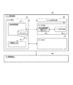
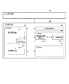
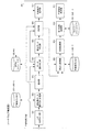
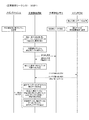
上記目的を達成するため、請求項1の発明は、遊技に関する制御を行う制御処理手段と、前記制御処理手段からの要求に応じて読み出し可能な認証用データを記憶する認証用データ記憶手段と、を具備する制御手段と、遊技に関する制御に用いられる遊技情報と、該遊技情報の読み出しの許否に用いられる署名データとを記憶する記憶手段とを具備し、前記制御処理手段は、前記遊技情報の読み出しが行われる際に、前記認証用データ記憶手段で記憶している認証用データを読み出す認証用データ読み出し手段と、前記認証用データ読み出し手段によって読み出した前記認証用データを用いて前記遊技情報とともに記憶している前記署名データが、前記遊技情報を用いた遊技に関する制御を許可するデータであるかを検証する検証手段と、前記検証手段により前記署名データが、前記遊技情報を用いた遊技の実行を許可できないデータであるとき、前記認証用データ記憶手段で記憶する認証用データを削除する削除手段と、をさらに具備し、前記削除手段による前記認証用データの削除によって前記認証用データ記憶手段から認証用データを読み出せないことにより前記検証手段による検証を不可能とすることを特徴とする。 To achieve the above object, a first aspect of the invention, a control processing unit that performs control related to a game, the authentication data storing means for storing the readable authentication data in response to a request from said control processing means, Control means, and storage means for storing game information used for control related to the game and signature data used for permission or disapproval of reading of the game information, and the control processing means When the reading is performed, the authentication data reading means for reading the authentication data stored in the authentication data storage means, and the game data using the authentication data read by the authentication data reading means Verification means for verifying whether the stored signature data is data permitting control related to a game using the game information; A deletion means for deleting authentication data stored in the authentication data storage means when the signature data by the verification means is data that cannot be permitted to execute a game using the game information; Since the authentication data cannot be read from the authentication data storage unit by deleting the authentication data by the deletion unit, the verification by the verification unit is made impossible.
本発明によれば、不正なデータによって遊技が行われることを防止できるようになるという効果を奏する。 According to the present invention, it is possible to prevent a game from being played by unauthorized data.
以下、本発明の実施の形態における遊技機を、図面を参照しながら具体的に説明する。 Hereinafter, a gaming machine according to an embodiment of the present invention will be specifically described with reference to the drawings.
(遊技機の構成)
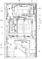
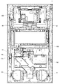
まず、図1〜図3を用いて、本発明の実施の形態における遊技機1の構成について具体的に説明する。図1は、遊技機の正面図の一例を示す図であり、図2は、キャビネット2の内部構造の一例を示す図である。また、図3は、前面扉3の裏面の一例を示す図である。
(Composition of gaming machine)
First, the configuration of the
(遊技機1)
本発明の実施の形態における遊技機1は、後述のキャビネット2と、前面扉3等から構成されている。
(Game machine 1)
The
(キャビネット2)
キャビネット2は、略矩形状の箱体であって、正面側に開口を有する。また、キャビネット2には、複数の部品が取り付けられている。
(Cabinet 2)
The
(前面扉3)
前面扉3は、キャビネット2の正面側の開口を閉塞するように取り付けられている。また前面扉3には、複数の部品が取り付けられている。
(Front door 3)
The
(蝶番機構4)
蝶番機構4は、キャビネット2の正面視左側に設けられており、前面扉3を開閉可能に軸支する。
(Hinge mechanism 4)
The
(鍵穴5)
鍵穴5は、前面扉3の中央右側に設けられ、施錠装置(図示せず)により前面扉3を開錠する。ここで、遊技店の店員等がメンテナンス作業や、設定値の変更等を行う場合に、前面扉3に設けられている施錠装置(図示せず)の開錠が行われる。まず、前面扉3の鍵穴5にドアキー(図示せず)を挿入して時計回り方向に所定角度回動することにより開錠する。次に、前面扉3を開放し、メンテナンス作業や、設定値の変更等の作業を行う。そして、メンテナンス作業や、設定値の変更等の作業が終了すると、前面扉3を閉じることにより施錠される。
(Keyhole 5)
The
(メダル投入口6)
メダル投入口6は、鍵穴5の正面視左側上方に設けられ、遊技者がメダルを投入する。
(Medal slot 6)
The
(BETボタン7)
BETボタン7は、後述のスタートランプ24の下方に設けられ、貯留(クレジット)されたメダルのうち、「1」枚のメダルを遊技に使用する。
(BET button 7)
The
(MAXBETボタン8)
MAXBETボタン8は、BETボタン7の正面視右側に設けられ、貯留(クレジット)されたメダルのうち、一遊技(「1」ゲーム)において使用可能な最大枚数のメダルを遊技に使用する。ここで、本実施形態において、一遊技で使用可能なメダルの最大値は「3」枚である。
(MAXBET button 8)
The
(精算ボタン9)
精算ボタン9は、BETボタン7の奥側に設けられ、遊技者が獲得したメダルのうち、貯留(クレジット)されているメダルの精算を行う。なお、本実施形態において、貯留(クレジット)可能なメダルの最大枚数は「50」枚である。
(Checkout button 9)
The
(スタートレバー10)
スタートレバー10は、BETボタン7の下方に設けられている。また、スタートレバー10は、遊技者が後述の左リール18、中リール19、右リール20の回転を開始する契機となる開始操作を行う。ここで、遊技者による開始操作が検出されたことに基づいて、後述のメイン制御基板300は、ハード乱数を取得する処理や、後述の左リール18、中リール19、右リール20の回転を開始する処理等を行う。
(Start lever 10)
The
(左停止ボタン11)
左停止ボタン11は、スタートレバー10の正面視右側に設けられ、遊技者が後述の左リール18の回転を停止する契機となる停止操作を行う。
(Left stop button 11)
The
(中停止ボタン12)
中停止ボタン12は、左停止ボタン11の正面視右側に設けられ、遊技者が後述の中リール19の回転を停止する契機となる停止操作を行う。
(Intermediate stop button 12)
The
(右停止ボタン13)
右停止ボタン13は、中停止ボタン12の正面視右側に設けられ、遊技者が後述の右リール20の回転を停止する契機となる停止操作を行う。
(Right stop button 13)
The
(返却ボタン14)
返却ボタン14は、右停止ボタン13の正面視右側に設けられ、メダル投入口6に投入されたメダルが後述のセレクター15に詰まった場合に、詰まったメダルを返却する。
(Return button 14)
The
(セレクター15)
セレクター15は、前面扉3の背面側に設けられ、メダル投入口6に投入されたメダルの材質や形状等が適正であるか否かを判別する。
(Selector 15)
The
(エラー解除センサ16s)
エラー解除センサ16sは、鍵穴5の背面側に設けられており、遊技機1で発生したエラーを解除する。ここで、エラー解除センサ16sは、発光部と受光部からなり、鍵穴5にドアキー(図示せず)を挿入し、当該ドアキー(図示せず)を反時計回り方向に所定角度回動させると、施錠部(図示せず)が回動することとなる。そして、受光部は、施錠部が回動することにより、発光部から発光された光を受光することができなくなる。これにより、エラー解除センサ16sは、遊技機1で発生したエラーを解除するためのエラー解除操作を検知することとなる。
(Error cancel
The
(ドア開閉センサ17s)
ドア開閉センサ17sは、鍵穴5の背面側に設けられており、前面扉3が開放しているか否かを検出する。ここで、ドア開閉センサ17sは、発光部と受光部からなり、鍵穴5にドアキー(図示せず)を挿入し、当該ドアキー(図示せず)を時計回り方向に所定角度回動させると、施錠部(図示せず)が回動することとなる。そして、受光部は、施錠部が回動することにより、発光部から発光された光を受光することができなくなる。これにより、ドア開閉センサ17sは、前面扉3の開放を検知することとなる。
(Door open /
The door open /
(左リール18)
左リール18は、キャビネット2の内部に設けられており、円筒状の構造を有している。また、左リール18の円筒状の構造の周面には、透光性のシートが装着されており、当該シートには、複数種類の図柄が一列に描かれている。そして、左リール18は、後述の左ステッピングモータ151により回転駆動され、複数種類の図柄が変動表示される。
(Left reel 18)
The
(中リール19)
中リール19は、キャビネット2の内部に設けられており、円筒状の構造を有している。また、中リール19の円筒状の構造の周面には、透光性のシートが装着されており、当該シートには、複数種類の図柄が一列に描かれている。そして、中リール19は、後述の中ステッピングモータ152により回転駆動され、複数種類の図柄が変動表示される。
(Middle reel 19)
The
(右リール20)
右リール20は、キャビネット2の内部に設けられており、円筒状の構造を有している。また、右リール20の円筒状の構造の周面には、透光性のシートが装着されており、当該シートには、複数種類の図柄が一列に描かれている。そして、右リール20は、後述の右ステッピングモータ153により回転駆動され、複数種類の図柄が変動表示される。
(Right reel 20)
The
(演出ボタン21)
演出ボタン21は、MAXBETボタン8の正面視右側に設けられており、遊技者が所定のタイミングで操作する。また、演出ボタン21が謳歌された場合に、後述の演出制御基板600を介して、後述の液晶表示装置46等の制御を行う。
(Direction button 21)
The
(十字キー22)
十字キー22は、演出ボタン21の正面視右側に設けられており、上方向ボタン、下方向ボタン、左方向ボタン、及び右方向ボタンにより構成され、遊技者が所定のタイミングで操作する。
(Cross key 22)
The cross key 22 is provided on the right side of the
(表示窓23)
表示窓23は、左リール18、中リール19、右リール20の前面側に設けられており、左リール18、中リール19、右リール20の周面に描かれた複数の図柄を視認可能とする。具体的には、左リール18の周面に描かれた「3」個の図柄、中リール19の周面に描かれた「3」個の図柄、及び右リール20の周面に描かれた「3」個の図柄の合計「9」個の図柄が表示窓23を介して視認可能となる。
(Display window 23)
The
(スタートランプ24)
スタートランプ24は、BETボタン7の上方に設けられており、スタートレバー10により開始操作を受け付けることが可能であるか否かを報知する。具体的には、後述のメイン制御基板300は、BETボタン7、MAXBETボタン8の操作により、遊技に使用するメダルの枚数が「3」枚となった場合や、メダル投入口6に「3」枚のメダルが投入された場合、前回の遊技において、後述の「リプレイ」に係る図柄の組み合わせが有効ライン上に表示された場合に、スタートランプ24を点灯することにより、スタートレバー10により開始操作を受け付けることが可能である旨を報知する処理を行う。
(Start lamp 24)
The
(有効ライン)
ここで、本実施形態において、有効ラインは、表示窓23に表示された図柄のうち、左リール18の上段に表示された図柄と、中リール19の中段に表示された図柄と、右リール20の下段に表示された図柄を直線で結んだ「右下がりライン」のみを有効ラインとしている。
(Effective line)
Here, in the present embodiment, among the symbols displayed on the
ここで、本実施形態において、表示窓23に表示された図柄のうち、(a)左リール18の上段に表示された図柄と、中リール19の上段に表示された図柄と、右リール20の上段に表示された図柄を直線で結んだラインを「上段ライン」といい、(b)左リール18の中段に表示された図柄と、中リール19の中段に表示された図柄と、右リール20の中段に表示された図柄を直線で結んだラインを「中段ライン」といい、(c)左リール18の下段に表示された図柄と、中リール19の下段に表示された図柄と、右リール20の下段に表示された図柄を直線で結んだラインを「下段ライン」といい、(d)左リール18の下段に表示された図柄と、中リール19の中段に表示された図柄と、右リール20の上段に表示された図柄を直線で結んだラインを「右上がりライン」という。なお、有効ラインは、右下がりラインではなく、上段ライン、中段ライン、下段ライン、右上がりラインを適用してもよいし、右下がりラインに加えて、上段ライン、中段ライン、下段ライン、右上がりラインを適用してもよい。
Here, in the present embodiment, among the symbols displayed on the
(第1BETランプ25)
第1BETランプ25は、スタートランプ24の正面視右側に設けられており、BET枚数が「1」枚であることを報知する。具体的には、後述のメイン制御基板300は、メダル投入口6に「1」枚以上のメダルが投入された場合や、メダルが「1」枚以上貯留(クレジット)されている状態において、BETボタン7、またはMAXBETボタン8が操作された場合等に、第1BETランプ25を点灯する処理を行う。
(First BET lamp 25)
The
(第2BETランプ26)
第2BETランプ26は、第1BETランプ25の上方に設けられており、BET枚数が「2」枚であることを報知する。具体的には、後述のメイン制御基板300は、メダル投入口6に「2」枚以上のメダルが投入された場合や、メダルが「2」枚以上貯留(クレジット)されている状態において、BETボタン7が「2」回操作された場合等に、第2BETランプ26を点灯する処理を行う。
(Second BET lamp 26)
The
(第3BETランプ27)
第3BETランプ27は、第2BETランプ26の上方に設けられており、BET枚数が「3」枚であることを報知する。具体的には、後述のメイン制御基板300は、メダル投入口6に「3」枚のメダルが投入された場合や、メダルが「3」枚以上貯留(クレジット)されている状態において、MAXBETボタン8が操作された場合、前回の遊技において、後述の「リプレイ」に係る図柄の組み合わせが有効ライン上に表示された場合等に、第3BETランプ27を点灯する処理を行う。
(3rd BET lamp 27)
The
(貯留枚数表示器28)
貯留枚数表示器28は、第1BETランプ25、第2BETランプ26、第3BETランプ27の正面視右側に設けられている。また、貯留枚数表示器28は、遊技機1に貯留(クレジット)されている遊技者のメダルの貯留(クレジット)枚数を表示する。
(Storage number indicator 28)
The stored
(払出枚数表示器29)
払出枚数表示器29は、貯留枚数表示器28の正面視右側に設けられている。また、払出枚数表示器29は、有効ライン上に表示された図柄の組み合わせに応じて払い出されるメダルの払出枚数を表示する。また、払出枚数表示器29は、遊技機1がエラー状態となった場合に、エラー状態になったことが表示される。
(Payout number display 29)
The
(投入可能表示ランプ30)
投入可能表示ランプ30は、払出枚数表示器29の正面視右側に設けられている。ここで、後述のメイン制御基板300は、メダル投入口6により、メダルの投入を受け付ける場合には、投入可能表示ランプ30を点灯させる処理を行う。一方、後述のメイン制御基板300は、メダル投入口6により、メダルの投入を受け付けない場合には、投入可能表示ランプ30を消灯させる処理を行う。これにより、遊技者に対して、メダル投入口6により、メダルの投入を受け付けるか否かの報知を行う。
(Putable indicator lamp 30)
The
(再遊技表示ランプ31)
再遊技表示ランプ31は、投入可能表示ランプ30の下方に設けられている。ここで、後述のメイン制御基板300は、有効ライン上に後述の「リプレイ」に係る図柄の組み合わせが表示された場合に、再遊技表示ランプ31を点灯させる処理を行う。一方、後述のメイン制御基板300は、有効ライン上に後述の「リプレイ」に係る図柄の組み合わせが表示された次の遊技において、有効ライン上に後述の「リプレイ」に係る図柄の組み合わせが表示されなかった場合には、再遊技表示ランプ31を消灯させる処理を行う。これにより、有効ライン上に「リプレイ」に係る図柄の組み合わせが表示されたことと、メダルを使用することなく、次の遊技を行うことが可能である旨の報知を行う。
(Replay display lamp 31)
The
(受皿ユニット38)
受皿ユニット38は、腰部パネル37の下方に設けられている。また、受皿ユニット38は、後述のメダル払出口39から排出されたメダルを受け入れて貯留する。
(Tray unit 38)
The
(メダル払出口39)
メダル払出口39は、腰部パネル37の下方に設けられており、メダルの払出が行われる場合において、後述のホッパー202により払い出されるメダルを排出する。また、メダル払出口39は、後述のセレクターセンサ15sにより、メダル投入口6に投入されたメダルが適正なメダルではないと判別された場合に、適正でないメダルを排出する。更に、メダル払出口39は、メダルの投入を受け付けることが不可能なタイミングに、メダル投入口6にメダルが投入された場合に、当該メダルの投入を受け付けることが不可能なタイミングで投入されたメダルを排出する。
(Medal payout exit 39)
The
(設定表示部44)
設定表示部44は、後述のメイン制御基板300に設けられており、遊技機1の設定値を表示する。ここで、後述のメイン制御基板300は、設定変更キー(図示せず)を後述の設定変更用鍵穴48に挿入した状態で時計回り方向に所定角度回動されている場合(時計回り方向に所定角度回動され続けている場合)に、現在設定されている設定値を設定表示部44に表示する処理を行う。この表示処理は、あくまで電源基板200からの電力の供給が行われている状態で、設定変更用鍵穴48に挿入された設定変更キーを時計回り方向に所定角度回動したときに行われる処理である。
(Setting display section 44)
The
これとは逆に、電源基板200からの電力供給が行われていない状態で、管理者等(以下、「管理者」と称する)が設定変更キーを設定変更用鍵穴48に挿入して初期位置から時計回り方向に所定角度回動し、その後、電源基板200からの電力供給が行われると、メイン制御基板300では、設定値を変更可能な状態に設定されることを示している。
On the other hand, in a state where power is not supplied from the
サブ制御基板400は、メイン制御基板300から設定変更開始コマンドを受信すると、演出制御基板600に対して設定変更に関する画面を液晶表示装置に表示させる処理を指示する。この「設定変更に関する画面」とは、設定変更中である旨を表示させるほか、他の操作を排他する旨を示す画面である。この演出制御基板600では、サブ制御基板400からの指示を受け付けることによって液晶表示装置46に設定変更に関する画面を表示させる。
When receiving the setting change start command from the
(設定変更ボタン45)
設定変更ボタン45は、後述の設定スイッチ基板250に設けられており、設定値を変更する。ここで、後述のメイン制御基板300は、設定表示部44に現在設定されている設定値が表示されている状態において、設定変更ボタン45の操作が検出された場合に、設定表示部44に表示されている設定値を、設定可能な範囲(上記に示す例では、「1」〜「6」までの全6種類)で順番に切り替えて表示する処理を行う。詳細については後述する。
(Setting change button 45)
The setting
そして、後述のメイン制御基板300は、現在設定されている設定値が設定表示部44に表示されている状態において、スタートレバー10の操作が検出された場合に、設定値を確定する処理を行う。この確定処理では、メインRAM303内の一時作業領域に変更後の設定値を記憶する処理を行う。すなわち、この確定処理によってメインRAM303の設定値を書き換える処理が行われるわけではない。
Then, the
なお、後述のメイン制御基板300は、遊技機1でエラーが発生した場合に、設定変更ボタン45の操作が検出されたことに基づいて、エラーを解除する処理を行う。
It should be noted that the
以上のことから、本実施形態において、設定変更ボタン45は、(a)設定値を切り替える機能と、(b)エラーを解除する機能とを有する。
From the above, in this embodiment, the setting
このようにして、設定変更用鍵穴48に設定変更キーを挿入した状態で初期位置から時計回り方向に所定角度回動されている状態で、設定変更ボタン45が管理者によって操作されることによって設定値を変更して上記の確定処理が行われたのち、管理者は、回動していた設定変更キーを元の角度に戻す操作を行うことが可能である。
In this way, the setting
管理者によって設定変更キーを元の角度に戻す操作が行われて初期位置に戻されると、メイン制御基板300は、上記に示すような確定処理によって確定してメインRAM303の一時作業領域に記憶されている変更後の設定値で、メインRAM303で記憶している設定値を書き換える処理(設定値変更処理)を行う。すなわち、設定値の変更が行われることを示している。
When the administrator performs an operation to return the setting change key to the original angle and returns to the initial position, the
なお、本実施形態において、設定値は、設定「1」から設定「6」の「6」段階の設定値が設けられている。このため、設定表示部44に設定「1」である旨の情報が表示されている状態において、設定変更ボタン45の操作が検出されると、設定表示部44に設定「2」である旨の情報が表示され、以降、設定変更ボタン45を操作する毎に、設定表示部44に表示される設定値が「1」ずつ加算して表示される。ただし、設定表示部44に設定「6」である旨の情報が表示されている状態において、設定変更ボタン45が操作されると、設定表示部44には設定「1」である旨の情報が表示されることとなる。
In the present embodiment, the setting values are set in the “6” stage from the setting “1” to the setting “6”. For this reason, when the operation of the setting
なお、本実施形態において、設定値は、設定「1」から設定「6」の「6」段階の設定値が設けられていることとしたが、これに限定されることはない。例えば、設定値は、「2」段階や、「3」段階でもよく、「4」段階や、「5」段階でもよい。 In the present embodiment, the setting values are set at the “6” stage from the setting “1” to the setting “6”. However, the setting value is not limited to this. For example, the set value may be the “2” stage, the “3” stage, the “4” stage, or the “5” stage.
(液晶表示装置46)
液晶表示装置46は、左リール18、中リール19、右リール20の上方に設けられ、動画像・静止画像等を表示する。ここで、後述のサブ制御基板400は、後述のサブ制御基板400により管理される状態がART状態である場合において、後述の内部抽選処理により「押し順ベルA1〜A4」、または「押し順ベルB1〜B4」の何れかが決定された場合等に、演出制御基板600を介して、左停止ボタン11、中停止ボタン12、右停止ボタン13の操作順序を液晶表示装置46に表示する処理を行う。
(Liquid crystal display device 46)
The liquid
(外部集中端子板47)
外部集中端子板47は、後述の設定スイッチ基板250の正面視右側下方に設けられ、ホールコンピュータ(図示せず)等の遊技機1の外部に対して、(a)遊技に使用したメダルの枚数を特定可能なメダル投入信号、(b)遊技者に対して払い出したメダルの枚数を特定可能なメダル払出信号、(c)後述のサブ制御基板400により管理される状態がART状態に移行した旨を特定可能なART状態信号、(d)後述のサブ制御基板400により管理される状態がBonus状態に移行したことを特定可能なBonus状態信号、(e)後述のサブ制御基板400により管理される状態がRUSH状態に移行したことを特定可能なRUSH状態信号、(f)不正行為が行われたことが特定可能なセキュリティ信号を送信する。
(External concentration terminal board 47)
The external
ここで、より具体的に説明すると、「ART状態信号」は、メイン制御基板300により管理される状態が第4RT遊技状態に移行した場合に出力される信号であり、「Bonus状態信号」は、メイン制御基板300により管理される状態が第3RT遊技状態に移行した場合に出力される信号であり、「RUSH状態信号」は、メイン制御基板300により管理される状態が第5RT遊技状態に移行した場合に出力される信号である。
More specifically, the “ART state signal” is a signal output when the state managed by the
(設定変更用鍵穴48)
設定変更用鍵穴48は、後述の設定スイッチ基板250に設けられ、設定値を変更する。また、設定変更用鍵穴48には、設定変更キー(図示せず)を設定変更用鍵穴48に挿入した状態で時計回り方向に所定角度回動されたことを検出する後述の設定変更キースイッチ49swが設けられている。
(Setting change keyhole 48)
The setting
(演出装置50)
演出装置50は、液晶表示装置46の前面側に設けられている。ここで、サブ制御基板400は、演出装置50を可動することが決定された場合には、演出制御基板600を介して、演出装置50を上下方向に可動する処理を行う。これにより、遊技者に対して視覚に訴える演出を行うことができる。
(Director 50)
The
(ランプ60)
ランプ60は、トップLED、コーナーLED、サイドLED、受皿サイドLED、受皿LED等のLED群によって構成されており、液晶表示装置46の上方に設けられている。また、このランプ60は、遊技者の視覚に訴える形状及び色彩、模様、絵柄等を施してデザイン設計されている。ここで、サブ制御基板400は、演出制御基板600を介してランプ60を点灯、点滅する処理を行う。これにより、遊技者に対して視覚に訴える演出を行うことができる。
(Lamp 60)
The
(ステータス基板100)
ステータス基板100は、前面扉3の背面側であって、表示窓23の下方に設けられている。また、ステータス基板100には、後述のBETスイッチ7sw、後述のMAXBETスイッチ8sw、後述の精算スイッチ9sw、後述のスタートスイッチ10sw、後述の左停止スイッチ11sw、後述の中停止スイッチ12sw、後述の右停止スイッチ13sw、後述のセレクターセンサ15s、エラー解除センサ16s、ドア開閉センサ17s、スタートランプ24、第1BETランプ25、第2BETランプ26、第3BETランプ27、貯留枚数表示器28、払出枚数表示器29、投入可能表示ランプ30、及び再遊技表示ランプ31が接続されている。
(Status board 100)
The
(リール制御基板150)
リール制御基板150は、左リール18、中リール19、右リール20の上方に設けられており、左リール18、中リール19、右リール20の回転、及び停止を制御する。また、リール制御基板150には、後述の左ステッピングモータ151、後述の中ステッピングモータ152、後述の右ステッピングモータ153、後述の左リールセンサ154s、後述の中リールセンサ155s、後述の右リールセンサ156sが接続されている。
(Reel control board 150)
The reel control board 150 is provided above the
(左ステッピングモータ151)
左ステッピングモータ151は、左リール18の内部に設けられており、左リール18の制御を行う。また、左ステッピングモータ151は、回転軸を指定された角度で停止させることが可能な構成を備えている。これにより、左リール18は、左ステッピングモータ151に対してパルス信号が出力されるごとに、一定の角度で回転する。なお、メイン制御基板300は、リールインデックスを検出してから左ステッピングモータ151に対してパルス信号を出力した回数をカウントすることによって、左リール18の回転角度を管理する。
(Left stepping motor 151)
The
(中ステッピングモータ152)
中ステッピングモータ152は、中リール19の内部に設けられており、中リール19の制御を行う。また、中ステッピングモータ152は、回転軸を指定された角度で停止させることが可能な構成を備えている。これにより、中リール19は、中ステッピングモータ152に対してパルス信号が出力されるごとに、一定の角度で回転する。なお、メイン制御基板300は、リールインデックスを検出してから中ステッピングモータ152に対してパルス信号を出力した回数をカウントすることによって、中リール19の回転角度を管理する。
(Medium stepping motor 152)
The
(右ステッピングモータ153)
右ステッピングモータ153は、右リール20の内部に設けられており、右リール20の制御を行う。また、右ステッピングモータ153は、回転軸を指定された角度で停止させることが可能な構成を備えている。これにより、右リール20は、右ステッピングモータ153に対してパルス信号が出力されるごとに、一定の角度で回転する。なお、メイン制御基板300は、リールインデックスを検出してから右ステッピングモータ153に対してパルス信号を出力した回数をカウントすることによって、右リール20の回転角度を管理する。
(Right stepping motor 153)
The
(左リールセンサ154s)
左リールセンサ154sは、左リール18の内部に設けられており、発光部と受光部とを有する光センサを備えている。また、左リールセンサ154sは、左リール18が「1」回転したことを示すリールインデックスを検出する。
(
The
(中リールセンサ155s)
中リールセンサ155sは、中リール19の内部に設けられており、発光部と受光部とを有する光センサを備えている。また、中リールセンサ155sは、中リール19が「1」回転したことを示すリールインデックスを検出する。
(
The
(右リールセンサ156s)
右リールセンサ156sは、右リール20の内部に設けられており、発光部と受光部とを有する光センサを備えている。また、右リールセンサ156sは、右リール20が「1」回転したことを示すリールインデックスを検出する。
(
The
(電源基板200)
電源基板200は、後述のホッパー202の正面視左側に設けられており、遊技機1に電力を供給する制御を行う。また、電源基板200には、後述の電源スイッチ201sw、後述のホッパー202、及び後述の補助収納庫センサ203sが接続されている。
(Power supply board 200)
The
(電源ボタン201)
電源ボタン201は、後述のホッパー202の正面視左側に設けられており、遊技機1に電力を供給する操作を行う。
(Power button 201)
The
(ホッパー202)
ホッパー202は、電源基板200の正面視右側に設けられており、遊技者に対してメダルを払い出す。ここで、後述のメイン制御基板300は、有効ライン上にメダルを払い出す図柄の組み合わせが表示された場合に、電源基板200を介してホッパー202を駆動する処理を行い、遊技者に対してメダルを払い出す処理を行う。
(Hopper 202)
The
(補助収納庫203)
補助収納庫203は、ホッパー202の正面視右側に設けられており、ホッパー202に貯留されているメダルが溢れた場合に、溢れたメダルを収納する。
(Auxiliary storage 203)
The
(設定スイッチ基板250)
設定スイッチ基板250は、後述のメイン制御基板300の正面視右側に設けられている。また、設定スイッチ基板250には、後述の設定変更スイッチ45sw、及び後述の設定変更キースイッチ49swが通信ケーブルによって接続されている。
(Setting switch board 250)
The setting
(メイン制御基板300)
メイン制御基板300は、キャビネット2の内部であって、設定スイッチ基板250の正面視左側に設けられており、遊技機1の制御を行う。また、メイン制御基板300は、後述のメインCPU301、後述のメインROM302、後述のメインRAM303、メイン乱数発生器304を備えている。更に、メイン制御基板300には、設定表示部44、外部集中端子板47、ステータス基板100、リール制御基板150、電源基板200、設定スイッチ基板250、後述のサブ制御基板400が通信ケーブルによって接続されている。
(Main control board 300)
The
このメイン制御基板300は、導線が所定の配線パターンで配線された絶縁材料板(非伝導材料(素材))に、メインCPU301、メインROM302、メインRAM303およびメイン乱数発生器304の各集積回路(IC)を所定の位置に実装したプリント配線基板によって構成される。
The
(サブ制御基板400)
サブ制御基板400は、メイン制御基板300の正面視左側に設けられており、主として演出の制御を行う。また、サブ制御基板400は、後述のサブCPU401、後述のサブROM402、後述のサブRAM403、後述のサブ乱数発生器404を備えている。更に、サブ制御基板400には、メイン制御基板300、後述の演出制御基板600、後述の中継基板700が通信ケーブルによって接続されている。
(Sub control board 400)
The
このサブ制御基板400は、上記のメイン制御基板300と同様に、導線が所定の配線パターンで配線された絶縁材料板(非伝導材料(素材))に、サブCPU401、サブROM402、サブRAM403およびサブ乱数発生器404の各集積回路(IC)を所定の位置に実装したプリント配線基板によって構成される。
Similar to the
(演出制御基板600)
演出制御基板600は、主として演出を実行する。また、演出制御基板600は、後述の液晶制御CPU601、後述の液晶制御ROM602、後述の液晶制御RAM603、後述のCGROM604、後述の音源IC605、後述の音源ROM606、後述のVDP607を備えている。更に、演出制御基板600には、液晶表示装置46、スピーカ40、演出装置50およびランプ60が通信ケーブルによって接続されている。
(Production control board 600)
The
この演出制御基板600は、上記のメイン制御基板300およびサブ制御基板400と同様に、導線が所定の配線パターンで配線された絶縁材料板(非伝導材料(素材))に、液晶制御CPU601、液晶制御ROM602、液晶制御RAM603、CGROM604、音源IC605、音源ROM606およびVDP607の各集積回路(IC)を所定の位置に実装したプリント配線基板によって構成される。
As in the case of the
(中継基板700)
中継基板700は、サブ制御基板400と、演出ボタン21および十字キー22とを中継する。
(Relay board 700)
The
(遊技機全体のブロック図)
次に、図4を用いて、遊技機1全体のブロック図について説明する。
(Block diagram of the entire gaming machine)
Next, a block diagram of the
遊技機1は、遊技機1の主たる動作を制御するメイン制御基板300に対して、ステータス基板100、リール制御基板150、電源基板200、設定スイッチ基板250、サブ制御基板400が通信ケーブルによって接続されている。
In the
(BETスイッチ7sw)
BETスイッチ7swは、BETボタン7の操作を検出するためのスイッチである。ここで、ステータス基板100は、BETスイッチ7swにより、BETボタン7の操作が検出された場合に、メイン制御基板300に対して所定の信号を送信する。そして、メイン制御基板300は、ステータス基板100から所定の信号を受信したことに基づいて、貯留(クレジット)されているメダルから「1」枚のメダルを使用する処理を行う。
(BET switch 7sw)
The BET switch 7sw is a switch for detecting the operation of the
(MAXBETスイッチ8sw)
MAXBETスイッチ8swは、MAXBETボタン8の操作を検出するためのスイッチである。ここで、ステータス基板100は、MAXBETスイッチ8swにより、MAXBETボタン8の操作が検出された場合に、メイン制御基板300に対して所定の信号を送信する。そして、メイン制御基板300は、ステータス基板100から所定の信号を受信したことに基づいて、貯留(クレジット)されているメダルから「3」枚のメダルを使用する処理を行う。
(MAXBET switch 8sw)
The MAXBET switch 8sw is a switch for detecting the operation of the
(精算スイッチ9sw)
精算スイッチ9swは、精算ボタン9の操作を検出するためのスイッチである。ここで、ステータス基板100は、精算スイッチ9swにより、精算ボタン9の操作が検出された場合に、メイン制御基板300に対して所定の信号を送信する。そして、メイン制御基板300は、ステータス基板100から所定の信号を受信したことに基づいて、貯留(クレジット)されているメダルを精算する処理を行う。具体的には、メイン制御基板300は、電源基板200に対して、貯留(クレジット)されているメダルを返却する旨の信号を送信する。そして、電源基板200は、ホッパー202を駆動することにより、貯留(クレジット)しているメダルを返却する処理を行う。
(Settlement switch 9sw)
The settlement switch 9sw is a switch for detecting the operation of the
(スタートスイッチ10sw)
スタートスイッチ10swは、スタートレバー10の操作を検出するためのスイッチである。ここで、ステータス基板100は、スタートスイッチ10swにより、スタートレバー10の操作が検出された場合に、メイン制御基板300に対して所定の信号を送信する。そして、メイン制御基板300は、ステータス基板100から所定の信号を受信したことに基づいて、左リール18、中リール19、右リール20の回転を開始する処理等を行う。
(Start switch 10sw)
The start switch 10sw is a switch for detecting the operation of the
(左停止スイッチ11sw)
左停止スイッチ11swは、左停止ボタン11の操作を検出するためのスイッチである。ここで、ステータス基板100は、左停止スイッチ11swにより、左停止ボタン11の操作が検出された場合に、メイン制御基板300に対して所定の信号を送信する。そして、メイン制御基板300は、ステータス基板100から所定の信号を受信したことに基づいて、回転中の左リール18を停止する処理を行う。
(Left stop switch 11sw)
The left stop switch 11sw is a switch for detecting an operation of the
(中停止スイッチ12sw)
中停止スイッチ12swは、中停止ボタン12の操作を検出するためのスイッチである。ここで、ステータス基板100は、中停止スイッチ12swにより、中停止ボタン12の操作が検出された場合に、メイン制御基板300に対して所定の信号を送信する。そして、メイン制御基板300は、ステータス基板100から所定の信号を受信したことに基づいて、回転中の中リール19を停止する処理を行う。
(Intermediate stop switch 12sw)
The middle stop switch 12sw is a switch for detecting the operation of the
(右停止スイッチ13sw)
右停止スイッチ13swは、右停止ボタン13の操作を検出するためのスイッチである。ここで、ステータス基板100は、右停止スイッチ13swにより、右停止ボタン13の操作が検出された場合に、メイン制御基板300に対して所定の信号を送信する。そして、メイン制御基板300は、ステータス基板100から所定の信号を受信したことに基づいて、回転中の右リール20を停止する処理を行う。
(Right stop switch 13sw)
The right stop switch 13sw is a switch for detecting the operation of the
(セレクターセンサ15s)
セレクターセンサ15sは、メダル投入口6に適正なメダルが投入されたことを検出するためのセンサである。ここで、ステータス基板100は、セレクターセンサ15sにより、正常なメダルの通過が検出された場合に、メイン制御基板300に対して所定の信号を送信する。そして、メイン制御基板300は、ステータス基板100から所定の信号を受信したことに基づいて、(a)貯留(クレジット)されるメダルの枚数を「1」加算する処理や、(b)遊技に使用するメダルの枚数に「1」加算する処理を行う。
(
The
(設定変更スイッチ45sw)
設定変更スイッチ45swは、設定変更ボタン45の操作を検出するためのスイッチである。ここで、設定スイッチ基板250は、設定変更スイッチ45swにより、設定変更ボタン45の操作が検出された場合に、メイン制御基板300に対して所定の信号を送信する。そして、メイン制御基板300は、設定スイッチ基板250から所定の信号を受信したことに基づいて、設定表示部44に表示されている設定値を更新して表示する処理を行う。
(Setting change switch 45sw)
The setting change switch 45sw is a switch for detecting an operation of the setting
(設定変更キースイッチ49sw)
設定変更キースイッチ49swは、設定変更キー(図示せず)が設定変更用鍵穴48に挿入された状態で、所定角度回動されたことを検出するためのスイッチである。ここで、設定スイッチ基板250は、設定変更キー(図示せず)が設定変更用鍵穴48に挿入された状態で、所定角度回動されたことが検出された場合に、メイン制御基板300に対して所定の信号を送信する。そして、メイン制御基板300は、設定スイッチ基板250から所定の信号を受信したことに基づいて、設定表示部44に現在の設定値を表示する処理を行う。
(Setting change key switch 49sw)
The setting change key switch 49sw is a switch for detecting that a setting change key (not shown) is rotated by a predetermined angle in a state where the setting change key (not shown) is inserted into the setting change
(電源スイッチ201sw)
電源スイッチ201swは、電源ボタン201の操作を検出するためのスイッチである。ここで、電源基板200は、電源スイッチ201swにより、電源ボタン201の操作が検出された場合に、遊技機1に電力を供給する処理を行う。
(Power switch 201sw)
The power switch 201sw is a switch for detecting an operation of the
(補助収納庫センサ203s)
補助収納庫センサ203sは、補助収納庫203に貯留されたメダルが満杯であることを検出するためのセンサである。ここで、電源基板200は、補助収納庫センサ203sにより、補助収納庫203に貯留されたメダルが満杯であることが検出された場合に、メイン制御基板300に対して、所定の信号を送信する。そして、メイン制御基板300は、電源基板200から所定の信号を受信したことに基づいて、補助収納庫203に貯留されたメダルが満杯である時のエラー処理を行う。
(Auxiliary storage sensor 203s)
The auxiliary storage sensor 203s is a sensor for detecting that medals stored in the
(メインCPU301)
メインCPU301は、後述のメインROM302に記憶されている各種のデータ(例えば、プログラム等)を読み込み、遊技の進行に合わせて所定の演算処理を行うことにより、ステータス基板100、リール制御基板150、電源基板200、サブ制御基板400に対して所定の信号を送信する。
(Main CPU 301)
The
このメインCPU301は、後述するように、キャッシュ(「メインキャッシュ」若しくは「メイン作業領域」と称する)を備えた主制御処理部と、不揮発性メモリとによって構成されており、BGA(Ball grid array)等によってパッケージングされている。
As will be described later, the
すなわち、メインCPU301は、主制御処理部、不揮発性メモリを有した単一の媒体であるIC(集積回路)から形成され、この主制御処理部、不揮発性メモリが一体形成されている。
That is, the
また、このメインCPU301が、メインROM302に記憶されている各種のデータ(遊技データ、遊技情報)を読み込む際には、後述する「不正読み出し対策処理」が行われる。
Further, when the
(メインROM302)
メインROM302は、メインCPU301により実行される制御プログラム、データテーブル、サブ制御基板400に対するコマンドを送信するためのデータ等からなる遊技情報を記憶する。具体的には、メインROM302は、後述の配列データテーブル(図6参照)、後述の図柄組み合わせ群が「00」の図柄組み合わせテーブル(図7参照)、後述の図柄組み合わせ群が「01」の図柄組み合わせテーブル(図8参照)、後述の図柄組み合わせ群が「02」の図柄組み合わせテーブル(図9参照)、後述の図柄組み合わせ群が「03」の図柄組み合わせテーブル(図10参照)、後述の図柄組み合わせ群が「04」の図柄組み合わせテーブル(図11参照)、後述の非RT遊技状態用第1当選役決定テーブル(図13参照)、後述の第1RT遊技状態用第1当選役決定テーブル(図14参照)、後述の第2RT遊技状態用第1当選役決定テーブル(図15参照)、後述の第3RT遊技状態用第1当選役決定テーブル(図16参照)、後述の第4RT遊技状態用第1当選役決定テーブル(図17参照)、後述の第5RT遊技状態用第1当選役決定テーブル(図18参照)、後述の第6RT遊技状態用第1当選役決定テーブル(図19参照)、後述の第2当選役決定テーブル(図20参照)等の遊技情報を記憶している。すなわち、遊技情報は、メインCPU301によって用いられる全ての情報を総括したものである。
(Main ROM 302)
The
(メインRAM303)
メインRAM303は、メインCPU301によるプログラムの実行により決定された各種データを記憶する。具体的には、メインRAM303には、例えば、投入枚数カウンタ等の各種カウンタや、設定変更装置作動異常フラグ格納領域等の各種格納領域が設けられている。このメインRAM303に記憶する各種データについてもメインCPU301によって用いられる情報であることから、広義の遊技情報であると言える。なお、以下では、サブCPU401において用いられ、サブROM402に記憶する情報も「遊技情報」と示しているものであって、このことから制御処理に用いられる情報を遊技情報とするものである。
(Main RAM 303)
The
(メイン乱数発生器304)
メイン乱数発生器304は、当選役を決定する抽選等で用いられる乱数を生成する。ここで、本実施形態において、メイン乱数発生器304は、「0」〜「65535」の範囲で乱数値を生成する。
(Main random number generator 304)
The main
(サブCPU401)
サブCPU401(「副制御チップ」ともいう)は、後述のサブROM402に記憶されている各種のデータ(例えば、プログラム等)を読み込み、メイン制御基板300から受信したコマンドの情報や、演出ボタン21、十字キー22から入力された信号に基づいて所定の演算を行い、当該演算の結果を演出制御基板600等に通知する。
(Sub CPU 401)
The sub CPU 401 (also referred to as “sub control chip”) reads various data (for example, a program) stored in a
このサブCPU401は、後述するように、メインCPU301と同様に、キャッシュ(「サブキャッシュ」若しくは「サブ作業領域」と称する)を備えた副制御処理部と、不揮発性メモリとが単一の媒体によって一体形成されており、この一体形成される媒体のパッケージングとして、BGA(Ball grid array)等がある。
As will be described later, the
すなわち、サブCPU401は、ハードウェア構成によって副制御処理部、不揮発性メモリを備えている。
That is, the
また、このサブCPU401が、サブROM402に記憶されている各種のデータを読み込む際には、後述する「不正読み出し対策処理」が行われる。
Further, when the
なお、上記においては、メインCPU301およびサブCPU401がそれぞれ、制御処理部(主制御処理部、副制御処理部)と、不揮発性メモリとを備えた構成を示しているが、これに限定されることなく、少なくとも一方(メインCPU301とサブCPU401の少なくとも一方)が、この構成であればよく、この構成を備えたメインCPU301またはサブCPU401が「不正読み出し対策処理」を行えばよい。
In the above description, the
(サブROM402)
サブROM402は、サブCPU401により実行される制御プログラム、データテーブル等を記憶する。具体的には、サブROM402は、後述の演出決定テーブル(図24参照)、後述のBonus準備状態移行抽選テーブル(図25参照)、後述のBonus状態振分抽選テーブル(図26参照)、後述の前兆ゲーム数決定テーブル(図27参照)、後述のチャンス状態移行抽選テーブル(図28参照)、後述のフェイクゲーム数決定テーブル(図29参照)、後述の昇格抽選テーブル(図30参照)、後述のART準備状態移行抽選テーブル(図31参照)、後述のART状態用ゲーム数上乗せ抽選テーブル(図32参照)、後述の引戻抽選テーブル(図33参照)、後述の上乗せ状態移行抽選テーブル(図34参照)等を記憶している。
(Sub ROM 402)
The
(サブRAM403)
サブRAM403は、サブCPU401によるプログラムの実行により決定された遊技に関する遊技関連情報を記憶可能である。この遊技関連情報は、遊技媒体の払い出しに関する情報のほか、遊技において用いられる演出に関する情報をも含む。具体的には、サブRAM403には、例えば、Bonus前兆状態用ゲーム数カウンタ等の各種カウンタや、各種の状態情報を格納する各種格納領域が設けられている。もちろん、この遊技関連情報は、サブRAM403で記憶する情報の一例に過ぎず、サブRAM403には、サブCPU401において用いられるさまざまな情報を記憶している。
(Sub RAM 403)
The
(サブ乱数発生器404)
サブ乱数発生器404は、演出を決定する抽選等で用いられる乱数を生成する。ここで、本実施形態において、サブ乱数発生器404は、「0」〜「65535」の範囲で乱数値を生成する。
(Sub-random number generator 404)
The
(液晶制御CPU601)
液晶制御CPU601は、後述の液晶制御ROM602に記憶されているプログラムを読み込み、サブ制御基板400から受信した信号に基づいてディスプレイリストを作成する。また、液晶制御CPU601は、後述のCGROM604に記憶されている画像データを液晶表示装置46に表示させる制御を行う。
(LCD control CPU 601)
The liquid crystal control CPU 601 reads a program stored in a liquid
(液晶制御ROM602)
液晶制御ROM602は、液晶制御CPU601により実行される制御プログラム、データテーブル等を記憶する。具体的には、液晶制御ROM602は、液晶制御CPU601の制御処理のプログラム、ディスプレイリストを生成するためのディスプレイリスト生成プログラム、アニメーションを表示する際に参照されるアニメシーンの組み合わせやアニメシーンの表示順序、画像の表示時間を示すウエイトフレーム、スプライトの識別番号や転送元アドレス等の各種対象データ、スプライトの表示位置や転送先アドレス等の各種パラメータ、描画方法等が記憶されている。
(LCD control ROM 602)
The liquid
(液晶制御RAM603)
液晶制御RAM603は液晶制御CPU601の演算処理時におけるデータのワークエリアとして機能し、液晶制御ROM602から読み出されたデータを一時的に記憶する。
(Liquid crystal control RAM 603)
The liquid
(CGROM604)
CGROM604は所定範囲の画素(例えば、「32」ピクセル×「32」ピクセル)における画素毎に色番号を指定する色番号情報と、画像の透明度を示すα値とから構成され画素情報の集合からなる画像データを圧縮して記憶する。
(CGROM604)
The CGROM 604 is composed of color number information that specifies a color number for each pixel in a predetermined range of pixels (for example, “32” pixels × “32” pixels) and an α value that indicates the transparency of the image, and consists of a set of pixel information. The image data is compressed and stored.
(音源IC605)
音源IC605は後述の音源ROM606に記憶されている音声に関するプログラムやデータを読み込み、スピーカ40を駆動する音声信号を生成する。
(Sound source IC 605)
The
(音源ROM606)
音源ROM606は演出を実行する際に出力される音声に関するプログラムやデータ等を記憶する。
(Sound source ROM 606)
The sound source ROM 606 stores a program, data, and the like related to sound that is output when an effect is executed.
(VDP607)
VDP607は、いわゆる画像プロセッサであり、液晶制御CPU601からの指示に基づいて、第1フレームバッファ領域と第2フレームバッファ領域のフレームバッファ領域のうち「表示用フレームバッファ領域」から画像データを読み出す制御を行う。そして、読み出した画像データに基づいて、映像信号(例えば、LVDS信号やRGB信号)を生成することにより、液晶表示装置46に画像を表示する制御が行われる。なお、VDP607は、図示しない制御レジスタ、CGバスインターフェイス、CPUインターフェイス、クロック生成回路、伸長回路、描画回路、表示回路、メモリコントローラ等を備えており、これらをバスによって接続している。
(VDP607)
The VDP 607 is a so-called image processor, and controls to read image data from the “display frame buffer area” out of the frame buffer areas of the first frame buffer area and the second frame buffer area based on an instruction from the liquid crystal control CPU 601. Do. Then, based on the read image data, a video signal (for example, an LVDS signal or an RGB signal) is generated, and thereby control for displaying an image on the liquid
(MAXBETボタンLED721)
MAXBETボタンLED721は、MAXBETボタン8の操作を受け付けるタイミングである場合には点灯し、MAXBETボタン8の操作を受け付けないタイミングである場合には消灯する。これにより、MAXBETボタン8の操作を受け付けるタイミングであることと、MAXBETボタン8の操作を受け付けないタイミングであることの報知を行う。
(MAX BET button LED721)
The MAXBET button LED 721 is turned on when it is time to accept the operation of the
(停止ボタンLED722)
停止ボタンLED722は、(a)左停止ボタン11の内部に設けられている左停止ボタンLED722Lと、(b)中停止ボタン12の内部に設けられている中停止ボタンLED722Cと、(c)右停止ボタン13の内部に設けられている右停止ボタンLED722Rを備えている。
(Stop button LED722)
The stop button LED 722 includes (a) a left stop button LED 722L provided inside the
(左停止ボタンLED722L)
左停止ボタンLED722Lは、左停止ボタン11の操作を受け付けるタイミングである場合には点灯し、左停止ボタン11の操作を受け付けないタイミングである場合には消灯する。
(Left stop button LED722L)
The left stop button LED 722L is turned on when it is time to accept the operation of the
(中停止ボタンLED722C)
中停止ボタンLED722Cは、中停止ボタン12の操作を受け付けるタイミングである場合には点灯し、中停止ボタン12の操作を受け付けないタイミングである場合には消灯する。
(Intermediate stop button LED722C)
The middle stop button LED 722C is turned on when it is time to accept the operation of the
(右停止ボタンLED722R)
右停止ボタンLED722Rは、右停止ボタン13の操作を受け付けるタイミングである場合には点灯し、右停止ボタン13の操作を受け付けないタイミングである場合には消灯する。
(Right stop button LED722R)
The right stop button LED 722R is turned on when it is time to accept the operation of the
(演出ボタンLED723)
演出ボタンLED723は、演出ボタン21の操作を受け付けるタイミングであることを報知する。
(Direction button LED723)
The effect button LED 723 notifies that it is time to accept the operation of the
(腰部パネルLED724)
腰部パネルLED724は、腰部パネル37に描かれた遊技機1の機種名やモチーフ等を遊技者へ認識させ易くする。
(Lumbar panel LED724)
The waist panel LED 724 makes it easy for the player to recognize the model name, motif, and the like of the
(演出装置50の可動態様)
次に、図5を用いて、演出装置50の可動態様について説明する。
(Moving aspect of the rendering device 50)
Next, the movable aspect of the
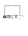
図5に示す通り、演出装置50は、ベース部51と、柄部52と、鞘部53を備えている。
As shown in FIG. 5, the
(ベース部51)
ベース部51は、演出装置50のベースとなる部材であって、鞘部53により被覆されている部分にLEDを内蔵している。ここで、サブ制御基板400は、所定の演出を実行する際に、演出制御基板600を介して、ベース部51に内蔵されているランプであるLEDを発光させる処理を行う。
(Base part 51)
The
(柄部52)
柄部52は、ベース部51の正面視左側に取り付けられている。また、柄部52は、日本刀の柄を模した形状をしている。また、柄部52は、左右方向に可動する。
(Pattern 52)
The
(鞘部53)
鞘部53は、ベース部51の正面視右側に取り付けられている。また、鞘部53は、日本刀の鞘を模した形状をしている。また、鞘部53は、左右方向に可動する。
(Sheath 53)
The
(配列データテーブル)
次に、図6に基づいて、配列データテーブルの説明を行う。
(Array data table)
Next, the array data table will be described with reference to FIG.
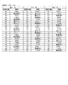
配列データテーブルは、メインROM302に設けられており、左リールセンサ154s、中リールセンサ155s、右リールセンサ156sがリールインデックスを検出したときに、表示窓23の中段に表示されている図柄の図柄位置を「00」と規定している。また、図柄位置「00」を基準として、図柄位置「00」〜「20」が規定されている。
The arrangement data table is provided in the
(図柄組み合わせ群が「00」の図柄組み合わせテーブル)
次に、図7に基づいて、図柄組み合わせ群が「00」の図柄組み合わせテーブルについて説明を行う。
(The symbol combination table whose symbol combination group is “00”)
Next, the symbol combination table whose symbol combination group is “00” will be described with reference to FIG.
図柄組み合わせ群が「00」の図柄組み合わせテーブルは、メインROM302に記憶されており、図柄の組み合わせ名称と、図柄組み合わせ名称に対応するビットと、当該ビットに対応する図柄ビット名称と、図柄の組み合わせと、遊技者に対して払い出すメダルの払出枚数を規定している。
The symbol combination table whose symbol combination group is “00” is stored in the
また、図柄組み合わせ群が「00」の図柄組み合わせテーブルのビット「00000001」には、図柄ビット名称「REP01」として「準備リプレイ」が規定されており、ビット「00000010」には、図柄ビット名称「REP02」として「第1Bonusリプレイ」が規定されており、ビット「00000100」には、図柄ビット名称「REP03」として「第2Bonusリプレイ」が規定されており、ビット「00001000」には、図柄ビット名称「REP04」として「第3Bonusリプレイ」が規定されており、ビット「00010000」には、図柄ビット名称「REP05」として「ARTリプレイ」が規定されており、ビット「00100000」には、図柄ビット名称「REP06」として「特別リプレイ」が規定されており、ビット「01000000」には、図柄ビット名称「REP07」として「RUSHリプレイ」が規定されており、ビット「10000000」には、図柄ビット名称「REP08」として「中段リプレイ」が規定されている。 In addition, “preparation replay” is defined as the symbol bit name “REP01” in the bit “00000001” of the symbol combination table whose symbol combination group is “00”, and the symbol bit name “REP02” is included in the bit “00000010”. "First Bonus replay" is defined, bit "00000100" is defined as symbol bit name "REP03", "second Bonus replay" is defined, and bit "00001000" is defined as symbol bit name "REP04". "3rd Bonus Replay" is defined, "ART Replay" is defined as the symbol bit name "REP05" in the bit "00010000", and the symbol bit name "REP06" is defined in the bit "00100000". As "Special Lip ”Is defined,“ RUSH replay ”is defined for the bit“ 01000000 ”as the symbol bit name“ REP07 ”, and“ middle stage replay ”is defined for the bit“ 10000000 ”as the symbol bit name“ REP08 ”. Is stipulated.
ここで、メインCPU301は、有効ライン上に沿って表示される図柄の組み合わせが、図柄組み合わせテーブルに規定されている図柄の組み合わせと一致する場合に、メダルの払出、再遊技の作動、遊技状態の移行といった特典を付与する制御を行う。例えば、有効ライン上に「再遊技A」、「再遊技A」、「BAR」の図柄の組み合わせが有効ライン上に表示されたとき、メインCPU301は、「準備リプレイ」に係る図柄の組み合わせが表示されたと判定し、再遊技の作動とともに、後述の第2RT遊技状態へ移行する制御を行う。なお、有効ラインに沿って表示された図柄の組み合わせが、図柄組み合わせテーブルに規定されている図柄の組み合わせと一致しない場合は、「ハズレ」となる。
Here, when the combination of symbols displayed along the active line matches the symbol combination specified in the symbol combination table, the
(図柄組み合わせ群が「01」の図柄組み合わせテーブル)
次に、図8に基づいて、図柄組み合わせ群が「01」の図柄組み合わせテーブルについて説明を行う。
(The symbol combination table whose symbol combination group is “01”)
Next, a symbol combination table whose symbol combination group is “01” will be described with reference to FIG.
図柄組み合わせ群が「01」の図柄組み合わせテーブルは、図柄組み合わせ群が「00」の図柄組み合わせテーブルと同様に、メインROM302に記憶されており、図柄の組み合わせ名称と、図柄組み合わせ名称に対応するビットと、当該ビットに対応する図柄ビット名称と、図柄の組み合わせと、遊技者に対して払い出すメダルの払出枚数を規定している。
Similar to the symbol combination table whose symbol combination group is “00”, the symbol combination table whose symbol combination group is “01” is stored in the
また、図柄組み合わせ群が「01」の図柄組み合わせテーブルのビット「00000001」には、図柄ビット名称「REP09」として「右上がりリプレイ」が規定されており、ビット「00000010」には、図柄ビット名称「REP10」として「BARリプレイ」が規定されており、ビット「00000100」には、図柄ビット名称「REP11」として「上段スイカリプレイ」が規定されており、ビット「00001000」には、図柄ビット名称「REP12」として「下段スイカリプレイ」が規定されており、ビット「00010000」には、図柄ビット名称「REP13」として「上段チェリーリプレイ」が規定されており、ビット「00100000」には、図柄ビット名称「REP14」として「下段チェリーリプレイ」が規定されており、ビット「01000000」には、図柄ビット名称「REP15」として「第1チャンス目リプレイ」が規定されており、ビット「10000000」には、図柄ビット名称「REP16」として「第2チャンス目リプレイ」が規定されている。 In addition, in the symbol combination table bit “00000001” of the symbol combination group “01”, “upward right replay” is defined as the symbol bit name “REP09”, and the symbol bit name “00000010” includes the symbol bit name “ “BAR replay” is defined as “REP10”, “upper watermelon play” is defined as symbol bit name “REP11” in bit “00000100”, and symbol bit name “REP12” is defined in bit “00001000”. "Lower watermelon play" is defined, bit "00010000" is defined as symbol bit name "REP13", "upper cherry replay" is defined, and bit "00100000" is defined as symbol bit name "REP14". "" "Rei" is defined, "First Chance Replay" is defined in the bit "01000000" as the symbol bit name "REP15", and "10000000" is defined as the symbol bit name "REP16". The “second chance replay” is defined.
ここで、本実施形態においては、「準備リプレイ」、「第1Bonusリプレイ」、「第2Bonusリプレイ」、「第3Bonusリプレイ」、「ARTリプレイ」、「特別リプレイ」、「RUSHリプレイ」、「中段リプレイ」、「右上がりリプレイ」、「BARリプレイ」、「上段スイカリプレイ」、「下段スイカリプレイ」、「上段チェリーリプレイ」、「下段チェリーリプレイ」、「第1チャンス目リプレイ」、「第2チャンス目リプレイ」に係る図柄の組み合わせが有効ライン上に表示された場合に、再遊技の作動が行われる。ここで、再遊技の作動が行われると、メダルを投入することなく、遊技を行うことができる。 Here, in this embodiment, “preparation replay”, “first bonus replay”, “second bonus replay”, “third bonus replay”, “ART replay”, “special replay”, “RUSH replay”, “middle replay”. ”,“ Upward right replay ”,“ BAR replay ”,“ upper watermelon play ”,“ lower watermelon play ”,“ upper cherry replay ”,“ lower cherry replay ”,“ first chance replay ”,“ second chance ” When the symbol combination related to “Replay” is displayed on the active line, the re-game is activated. Here, when the re-game operation is performed, the game can be performed without inserting medals.
(図柄組み合わせ群が「02」の図柄組み合わせテーブル)
次に、図9に基づいて、図柄組み合わせ群が「02」の図柄組み合わせテーブルについて説明を行う。
(The symbol combination table whose symbol combination group is “02”)
Next, the symbol combination table whose symbol combination group is “02” will be described with reference to FIG.
図柄組み合わせ群が「02」の図柄組み合わせテーブルは、図柄組み合わせ群が「00」の図柄組み合わせテーブルや、図柄組み合わせ群が「01」の図柄組み合わせテーブルと同様に、メインROM302に記憶されており、図柄の組み合わせ名称と、図柄組み合わせ名称に対応するビットと、当該ビットに対応する図柄ビット名称と、図柄の組み合わせと、遊技者に対して払い出すメダルの払出枚数を規定している。
The symbol combination table with the symbol combination group “02” is stored in the
また、図柄組み合わせ群が「02」の図柄組み合わせテーブルのビット「00000001」には、図柄ビット名称「NML01」として「第1押し順ベル」が規定されており、ビット「00000010」には、図柄ビット名称「NML02」として「第2押し順ベル」が規定されており、ビット「00000100」には、図柄ビット名称「NML03」として「第3押し順ベル」が規定されており、ビット「00001000」には、図柄ビット名称「NML04」として「第4押し順ベル」が規定されており、ビット「00010000」には、図柄ビット名称「NML05」として「第5押し順ベル」が規定されており、ビット「00100000」には、図柄ビット名称「NML06」として「第6押し順ベル」が規定されており、ビット「01000000」には、図柄ビット名称「NML07」として「第7押し順ベル」が規定されており、ビット「10000000」には、図柄ビット名称「NML08」として「第8押し順ベル」が規定されている。 Also, in the symbol combination table bit “00000001” of the symbol combination group “02”, “first push order bell” is defined as the symbol bit name “NML01”, and the symbol “00000010” includes the symbol bit. The name “NML02” is defined as “second push order bell”, the bit “00000100” is designated as the symbol bit name “NML03”, “third push order bell”, and the bit “00001000” is designated. “4th push order bell” is defined as the design bit name “NML04”, and “5th push order bell” is defined as the design bit name “NML05” in the bit “00010000”. “00100000” defines “sixth push order bell” as the symbol bit name “NML06”. The bit “01000000” defines the “seventh push order bell” as the symbol bit name “NML07”, and the bit “10000000” has the “eighth push order bell” as the symbol bit name “NML08”. It is prescribed.
(図柄組み合わせ群が「03」の図柄組み合わせテーブル)
次に、図10に基づいて、図柄組み合わせ群が「03」の図柄組み合わせテーブルについて説明を行う。
(The symbol combination table whose symbol combination group is “03”)
Next, the symbol combination table whose symbol combination group is “03” will be described with reference to FIG.
図柄組み合わせ群が「03」の図柄組み合わせテーブルは、図柄組み合わせ群が「00」の図柄組み合わせテーブルや、図柄組み合わせ群が「01」の図柄組み合わせテーブル、図柄組み合わせ群が「02」の図柄組み合わせテーブルと同様に、メインROM302に記憶されており、図柄の組み合わせ名称と、図柄組み合わせ名称に対応するビットと、当該ビットに対応する図柄ビット名称と、図柄の組み合わせと、遊技者に対して払い出すメダルの払出枚数を規定している。
The symbol combination table with the symbol combination group “03” includes the symbol combination table with the symbol combination group “00”, the symbol combination table with the symbol combination group “01”, and the symbol combination table with the symbol combination group “02”. Similarly, stored in the
また、図柄組み合わせ群が「03」の図柄組み合わせテーブルのビット「00000001」には、図柄ビット名称「NML09」として「第9押し順ベル」が規定されており、ビット「00000010」には、図柄ビット名称「NML10」として「第10押し順ベル」が規定されており、ビット「00000100」には、図柄ビット名称「NML11」として「第11押し順ベル」が規定されており、ビット「00001000」には、図柄ビット名称「NML12」として「第12押し順ベル」が規定されており、ビット「00010000」には、図柄ビット名称「NML13」として「正解ベル」が規定されており、ビット「00100000」には、図柄ビット名称「NML14」として「右上がりスイカ」が規定されており、ビット「01000000」には、図柄ビット名称「NML15」として「右下がりスイカ」が規定されており、ビット「10000000」には、図柄ビット名称「NML16」として「第1チャンス目」が規定されている。 In addition, in the symbol combination table bit “00000001” in which the symbol combination group is “03”, the symbol bit name “NML09” is defined as “9th push order bell”, and the symbol “00000010” includes symbol bits. “10th push order bell” is defined as the name “NML10”, “11th push order bell” is defined as the design bit name “NML11” in the bit “00000100”, and the bit “00001000” Is defined with the symbol bit name “NML12” as “12th pushing order bell”, the bit “00010000” is defined with the symbol bit name “NML13” as “correct answer bell”, and the bit “00100000”. Has a bit name “NML14” and “watermelon that goes up to the right” The bit “01000000” is defined as “Right-down watermelon” as the symbol bit name “NML15”, and the bit “10000000” is defined as “first chance” as the symbol bit name “NML16”. Yes.
(図柄組み合わせ群が「04」の図柄組み合わせテーブル)
次に、図11に基づいて、図柄組み合わせ群が「04」の図柄組み合わせテーブルについて説明を行う。
(The symbol combination table whose symbol combination group is “04”)
Next, a symbol combination table whose symbol combination group is “04” will be described with reference to FIG.
図柄組み合わせ群が「04」の図柄組み合わせテーブルは、図柄組み合わせ群が「00」の図柄組み合わせテーブルや、図柄組み合わせ群が「01」の図柄組み合わせテーブル、図柄組み合わせ群が「02」の図柄組み合わせテーブル、図柄組み合わせ群が「03」の図柄組み合わせテーブルと同様に、メインROM302に記憶されており、図柄の組み合わせ名称と、図柄組み合わせ名称に対応するビットと、当該ビットに対応する図柄ビット名称と、図柄の組み合わせと、遊技者に対して払い出すメダルの払出枚数を規定している。
The symbol combination table whose symbol combination group is “04” is a symbol combination table whose symbol combination group is “00”, a symbol combination table whose symbol combination group is “01”, a symbol combination table whose symbol combination group is “02”, Similar to the symbol combination table whose symbol combination group is “03”, it is stored in the
また、図柄組み合わせ群が「04」の図柄組み合わせテーブルのビット「00000001」には、図柄ビット名称「NML17」として「第2チャンス目」が規定されており、ビット「00000010」には、図柄ビット名称「NML18」として「第1チェリー」が規定されており、ビット「00000100」には、図柄ビット名称「NML19」として「第2チェリー」が規定されており、ビット「00001000」には、図柄ビット名称「NML20」として「中段チェリー」が規定されており、ビット「00010000」には、図柄ビット名称「BLK01」として「第1ブランク」が規定されており、ビット「00100000」には、図柄ビット名称「BLK02」として「第2ブランク」が規定されており、ビット「01000000」には、図柄ビット名称「BLK03」として「第3ブランク」が規定されており、ビット「10000000」には、図柄ビット名称「BLK04」として「第4ブランク」が規定されている。 In addition, in the symbol combination table with the symbol combination group “04”, the bit “00000001” defines “second chance” as the symbol bit name “NML17”, and the bit “00000010” includes the symbol bit name. “NML18” defines “first cherry”, bit “00000100” defines symbol bit name “NML19”, “second cherry”, and bit “00001000” includes symbol bit name “NML20” defines “middle stage cherry”, bit “00010000” defines symbol bit name “BLK01”, “first blank”, and bit “00100000” includes symbol bit name “ BLK02 "is defined as" second blank "and bit To 01000000 ", as the symbol bit name" BLK03 "" third blank "are defined, the bit" 10000000 "is" fourth blank "is defined as the symbol bit name" BLK04 ".
ここで、本実施形態においては、「第1押し順ベル」に係る図柄の組み合わせ、「第2押し順ベル」に係る図柄の組み合わせ、「第3押し順ベル」に係る図柄の組み合わせ、「第4押し順ベル」に係る図柄の組み合わせ、「第5押し順ベル」に係る図柄の組み合わせ、「第6押し順ベル」に係る図柄の組み合わせ、「第7押し順ベル」に係る図柄の組み合わせ、「第8押し順ベル」に係る図柄の組み合わせ、「第9押し順ベル」に係る図柄の組み合わせ、「第10押し順ベル」に係る図柄の組み合わせ、「第11押し順ベル」に係る図柄の組み合わせ、「第12押し順ベル」に係る図柄の組み合わせ、「正解ベル」に係る図柄の組み合わせ、「右上がりスイカ」に係る図柄の組み合わせ、「右下がりスイカ」に係る図柄の組み合わせ、「第1チャンス目」に係る図柄の組み合わせ」、「第2チャンス目」に係る図柄の組み合わせ、「第1チェリー」に係る図柄の組み合わせ、「第2チェリー」に係る図柄の組み合わせ、「中段チェリー」に係る図柄の組み合わせが有効ライン上に表示された場合に、メダルの払出が行われる。 Here, in the present embodiment, a combination of symbols relating to “first push order bell”, a combination of symbols relating to “second push order bell”, a combination of symbols relating to “third push order bell”, “ A combination of symbols related to “4 push order bell”, a combination of symbols related to “5th push order bell”, a combination of symbols related to “6th push order bell”, a combination of symbols related to “7th push order bell”, The combination of symbols related to “8th push order bell”, the combination of symbols related to “9th push order bell”, the combination of symbols related to “10th push order bell”, and the design related to “11th push order bell” Combination, symbol combination related to “12th push order bell”, symbol combination related to “correct answer bell”, symbol combination related to “right rising watermelon”, symbol combination related to “right falling watermelon”, “first "Combination of symbols related to" Cancele "," Combination of symbols related to "Second Chance", Combination of symbols related to "First Cherry", Combination of symbols related to "Second Cherry", When a combination of symbols is displayed on the active line, a medal is paid out.
なお、「第1押し順ベル」に係る図柄の組み合わせ、「第2押し順ベル」に係る図柄の組み合わせ、「第3押し順ベル」に係る図柄の組み合わせ、「第4押し順ベル」に係る図柄の組み合わせ、「第5押し順ベル」に係る図柄の組み合わせ、「第6押し順ベル」に係る図柄の組み合わせ、「第7押し順ベル」に係る図柄の組み合わせ、「第8押し順ベル」に係る図柄の組み合わせ、「第9押し順ベル」に係る図柄の組み合わせ、「第10押し順ベル」に係る図柄の組み合わせ、「第11押し順ベル」に係る図柄の組み合わせ、「第12押し順ベル」に係る図柄の組み合わせ、「正解ベル」に係る図柄の組み合わせ、「右上がりスイカ」に係る図柄の組み合わせ、「右下がりスイカ」に係る図柄の組み合わせ、「第1チャンス目」に係る図柄の組み合わせ、「第2チャンス目」に係る図柄の組み合わせ、「第1チェリー」に係る図柄の組み合わせ、「第2チェリー」に係る図柄の組み合わせ、「中段チェリー」に係る図柄の組み合わせを総称して、「入賞」に係る図柄の組み合わせという。 In addition, a combination of symbols related to “first push order bell”, a combination of symbols related to “second push order bell”, a combination of symbols related to “third push order bell”, and a “fourth push order bell” A combination of symbols, a combination of symbols related to "5th push order bell", a combination of symbols related to "6th push order bell", a combination of symbols related to "7th push order bell", and an "8th push order bell" A combination of symbols related to “9th push order bell”, a combination of symbols related to “10th push order bell”, a combination of symbols related to “11th push order bell”, “12th push order” The combination of symbols relating to "Bell", the combination of symbols relating to "Bell", the combination of symbols relating to "Right-up watermelon", the combination of symbols relating to "Right-down watermelon", and the symbol relating to "First chance" Collectively, symbol combination related to “second chance”, symbol combination related to “first cherry”, symbol combination related to “second cherry”, symbol combination related to “middle cherries” This is a combination of symbols related to “winning”.
また、「第1押し順ベル」に係る図柄の組み合わせ、「第2押し順ベル」に係る図柄の組み合わせ、「第3押し順ベル」に係る図柄の組み合わせ、「第4押し順ベル」に係る図柄の組み合わせ、「第5押し順ベル」に係る図柄の組み合わせ、「第6押し順ベル」に係る図柄の組み合わせ、「第7押し順ベル」に係る図柄の組み合わせ、「第8押し順ベル」に係る図柄の組み合わせ、「第9押し順ベル」に係る図柄の組み合わせ、「第10押し順ベル」に係る図柄の組み合わせ、「第11押し順ベル」に係る図柄の組み合わせ、「第12押し順ベル」に係る図柄の組み合わせを総称して「押し順ベル」に係る図柄の組み合わせという。 In addition, a combination of symbols relating to “first push order bell”, a combination of symbols relating to “second push order bell”, a combination of symbols relating to “third push order bell”, and a “fourth push order bell” A combination of symbols, a combination of symbols related to "5th push order bell", a combination of symbols related to "6th push order bell", a combination of symbols related to "7th push order bell", and an "8th push order bell" A combination of symbols related to “9th push order bell”, a combination of symbols related to “10th push order bell”, a combination of symbols related to “11th push order bell”, “12th push order” A combination of symbols relating to “bell” is collectively referred to as a combination of symbols relating to “push order bell”.
また、「第1押し順ベル」に係る図柄の組み合わせ、「第2押し順ベル」に係る図柄の組み合わせ、「第3押し順ベル」に係る図柄の組み合わせ、「第4押し順ベル」に係る図柄の組み合わせ、「第5押し順ベル」に係る図柄の組み合わせ、「第6押し順ベル」に係る図柄の組み合わせ、「第7押し順ベル」に係る図柄の組み合わせ、「第8押し順ベル」に係る図柄の組み合わせ、「第9押し順ベル」に係る図柄の組み合わせ、「第10押し順ベル」に係る図柄の組み合わせ、「第11押し順ベル」に係る図柄の組み合わせ、「第12押し順ベル」に係る図柄の組み合わせ、「正解ベル」に係る図柄の組み合わせを総称して「ベル」に係る図柄の組み合わせという。 In addition, a combination of symbols relating to “first push order bell”, a combination of symbols relating to “second push order bell”, a combination of symbols relating to “third push order bell”, and a “fourth push order bell” A combination of symbols, a combination of symbols related to "5th push order bell", a combination of symbols related to "6th push order bell", a combination of symbols related to "7th push order bell", and an "8th push order bell" A combination of symbols related to “9th push order bell”, a combination of symbols related to “10th push order bell”, a combination of symbols related to “11th push order bell”, “12th push order” A combination of symbols relating to “bell” and a combination of symbols relating to “correct bell” are collectively referred to as a combination of symbols relating to “bell”.
また、「右上がりスイカ」に係る図柄の組み合わせ、「右下がりスイカ」に係る図柄の組み合わせを総称して「スイカ」に係る図柄の組み合わせという。 In addition, a combination of symbols related to “rising watermelon” and a combination of symbols related to “downward watermelon” are collectively referred to as a combination of symbols related to “watermelon”.
また、「第1チャンス目」に係る図柄の組み合わせ、「第2チャンス目」に係る図柄の組み合わせを総称して「チャンス目」に係る図柄の組み合わせという。 In addition, a combination of symbols related to “first chance” and a combination of symbols related to “second chance” are collectively referred to as a combination of symbols related to “chance”.
また、「第1チェリー」に係る図柄の組み合わせ、「第2チェリー」に係る図柄の組み合わせ、「中段チェリー」に係る図柄の組み合わせを総称して「チェリー」に係る図柄の組み合わせという。 In addition, a symbol combination related to “first cherry”, a symbol combination related to “second cherry”, and a symbol combination related to “middle cherry” are collectively referred to as a symbol combination related to “cherry”.
また、「第1ブランク」に係る図柄の組み合わせ、「第2ブランク」に係る図柄の組み合わせ、「第3ブランク」に係る図柄の組み合わせ、「第4ブランク」に係る図柄の組み合わせを総称して、「ブランク」に係る図柄の組み合わせという。 In addition, a combination of symbols related to “first blank”, a combination of symbols related to “second blank”, a combination of symbols related to “third blank”, and a combination of symbols related to “fourth blank” This is a combination of symbols related to “blank”.
一方、「準備リプレイ」に係る図柄の組み合わせ、「第1Bonusリプレイ」に係る図柄の組み合わせ、「第2Bonusリプレイ」に係る図柄の組み合わせ、「第3Bonusリプレイ」に係る図柄の組み合わせ、「ARTリプレイ」に係る図柄の組み合わせ、「特別リプレイ」に係る図柄の組み合わせ、「RUSHリプレイ」に係る図柄の組み合わせ、「中段リプレイ」に係る図柄の組み合わせ、「右上がりリプレイ」に係る図柄の組み合わせ、「BARリプレイ」に係る図柄の組み合わせ、「上段スイカリプレイ」に係る図柄の組み合わせ、「下段スイカリプレイ」に係る図柄の組み合わせ、「上段チェリーリプレイ」に係る図柄の組み合わせ、「下段チェリーリプレイ」に係る図柄の組み合わせ、「第1チャンス目リプレイ」に係る図柄の組み合わせ、「第2チャンス目リプレイ」に係る図柄の組み合わせを総称して、「リプレイ」に係る図柄の組み合わせという。 On the other hand, the symbol combination related to “Preparation Replay”, the symbol combination related to “First Bonus Replay”, the symbol combination related to “Second Bonus Replay”, the symbol combination related to “Third Bonus Replay”, and “ART Replay” A combination of symbols, a combination of symbols related to “Special Replay”, a combination of symbols related to “RUSH Replay”, a combination of symbols related to “Middle Replay”, a combination of symbols related to “Right Up Replay”, “BAR Replay” A combination of symbols related to `` upper watermelon play '', a combination of symbols related to `` lower watermelon play '', a combination of symbols related to `` upper cherry replay '', a combination of symbols related to `` lower cherry replay '', Responsible for "First Chance Replay" Combination of symbols, are collectively the combination of symbols relating to the "second chance eyes Replay", that the combination of symbols relating to the "Replay".
また、「第1Bonusリプレイ」に係る図柄の組み合わせ、「第2Bonusリプレイ」に係る図柄の組み合わせ、「第3Bonusリプレイ」に係る図柄の組み合わせを総称して「Bonusリプレイ」に係る図柄の組み合わせという。 In addition, a symbol combination related to “First Bonus Replay”, a symbol combination related to “Second Bonus Replay”, and a symbol combination related to “Third Bonus Replay” are collectively referred to as a symbol combination related to “Bonus Replay”.
また、「中段リプレイ」に係る図柄の組み合わせ、「右上がりリプレイ」に係る図柄の組み合わせを総称して「通常リプレイ」に係る図柄の組み合わせという。 Further, a symbol combination related to “middle replay” and a symbol combination related to “upward replay” are collectively referred to as a symbol combination related to “normal replay”.
また、「上段スイカリプレイ」に係る図柄の組み合わせ、「下段スイカリプレイ」に係る図柄の組み合わせを総称して「スイカリプレイ」に係る図柄の組み合わせという。 In addition, a combination of symbols related to “upper watermelon play” and a combination of symbols related to “lower watermelon play” are collectively referred to as a combination of symbols related to “watermelon play”.
また、「上段チェリーリプレイ」に係る図柄の組み合わせ、「下段チェリーリプレイ」に係る図柄の組み合わせを総称して「チェリーリプレイ」に係る図柄の組み合わせという。 In addition, a symbol combination related to “upper cherry replay” and a symbol combination related to “lower cherry replay” are collectively referred to as a symbol combination related to “cherry replay”.
また、「第1チャンス目リプレイ」に係る図柄の組み合わせ、「第2チャンス目リプレイ」に係る図柄の組み合わせを総称して「チャンス目リプレイ」に係る図柄の組み合わせという。 In addition, the symbol combination related to “first chance replay” and the symbol combination related to “second chance replay” are collectively referred to as a symbol combination related to “chance eye replay”.
(当選役と、停止ボタンの操作順序と、入賞等の関係)
次に、図12に基づいて、当選役と、停止ボタンの操作順序と、入賞等の関係について説明を行う。
(Relationship between winning role, stop button operation order, winnings, etc.)
Next, based on FIG. 12, the relationship between the winning combination, the operation order of the stop button, and winnings will be described.
図12では、当選役に対応する当選番号と、当選番号の内容と、当選役に対応する条件装置と、各遊技状態で当選役として決定され得るか否かと、停止操作順序により有効ライン上に表示され得る図柄の組み合わせとの関係を示している。 In FIG. 12, the winning number corresponding to the winning combination, the contents of the winning number, the condition device corresponding to the winning combination, whether or not each game state can be determined as the winning combination, and the stop operation order are on the active line. The relationship with the combination of the symbols which can be displayed is shown.
また、図12に示す通り、決定された当選役によって、作動することとなる条件装置が異なる。例えば、後述の内部抽選処理により、当選番号「13」の当選役が決定された場合、作動することとなる条件装置は「REP08」、及び「REP09」である。即ち、当選番号「13」の当選役が決定された場合、「中段リプレイ」に係る図柄の組み合わせ、または「右上がりリプレイ」に係る図柄の組み合わせのうち、何れかの図柄の組み合わせが有効ライン上に表示されることとなる。 In addition, as shown in FIG. 12, the condition device to be operated varies depending on the determined winning combination. For example, when the winning combination of the winning number “13” is determined by the internal lottery process described later, the condition devices that are to be activated are “REP08” and “REP09”. In other words, when the winning combination of the winning number “13” is determined, any combination of symbols related to “middle replay” or symbol combination related to “upward replay” is on the active line. Will be displayed.
また、本実施形態において、同じ図柄位置で左停止ボタン11、中停止ボタン12、右停止ボタン13を操作しても、遊技者による左停止ボタン11、中停止ボタン12、右停止ボタン13の操作順序によって、有効ライン上に揃う図柄の組み合わせが異なる当選役が設けられている。例えば、後述の内部抽選処理により、当選番号「17」の「Bonus中リプレイBR1」が当選役として決定された場合に、作動することとなる条件装置は「REP08」、「REP09」、「REP10」、「REP12」、及び「REP15」である。この場合において、左停止ボタン11を最初に操作した場合には、「中段リプレイ」、「右上がりリプレイ」、「BARリプレイ」、または「下段スイカリプレイ」に係る図柄の組み合わせのうち、何れかの図柄の組み合わせが有効ライン上に表示されることとなる。また、中停止ボタン12を最初に操作した場合には、「中段リプレイ」に係る図柄の組み合わせが有効ライン上に表示されることとなる。また、右停止ボタン13を最初に操作した場合には、「中段リプレイ」、または「BARリプレイ」に係る図柄の組み合わせのうち、何れかの図柄の組み合わせが有効ライン上に表示されることとなる。
In this embodiment, even if the
ただし、この場合において、左停止ボタン11を最初に操作した場合には、「BARリプレイ」に係る図柄の組み合わせのうち、有効ライン上に表示することが許容される図柄の組み合わせと、有効ライン上に表示することが許容されない図柄の組み合わせがある。同様に、右停止ボタン13を最初に操作した場合にも、「BARリプレイ」に係る図柄の組み合わせのうち、有効ライン上に表示することが許容される図柄の組み合わせと、有効ライン上に表示することが許容されない図柄の組み合わせがある。
However, in this case, when the
一方、左停止ボタン11、中停止ボタン12、右停止ボタン13の操作順序がどのような順序であっても、有効ライン上に揃う図柄の組み合わせが異なることのない当選役が設けられている。例えば、後述の内部抽選処理により、当選番号「31」の「共通ベル」が当選役として決定された場合に、作動することとなる条件装置は「NML01」、「NML02」、「NML03」、「NML04」、「NML05」、「NML06」、「NML07」、「NML08」、「NML09」、「NML10」、「NML11」、「NML12」、及び「NML13」である。この場合においては、左停止ボタン11を最初に操作した場合、中停止ボタン12を最初に操作した場合、右停止ボタン13を最初に操作した場合の何れの場合であっても、「第1押し順ベル」、「第2押し順ベル」、「第3押し順ベル」、「第4押し順ベル」、または「正解ベル」に係る図柄の組み合わせのうち、何れかの図柄の組み合わせが有効ライン上に表示されることとなる。
On the other hand, a winning combination is provided in which the combination of symbols arranged on the active line does not differ regardless of the order of operation of the
また、左停止ボタン11、中停止ボタン12、右停止ボタン13の操作順序がどのような順序であっても、適切なタイミングで左停止ボタン11、中停止ボタン12、右停止ボタン13の操作がなされなければ、「入賞」に係る図柄の組み合わせが有効ライン上に表示されない場合がある。例えば、後述の内部抽選処理により、当選番号「25」の「スイカ」が当選役として決定された場合に、作動することとなる条件装置は「NML14」、及び「NML15」である。この場合においては、左停止ボタン11を最初に操作した場合、中停止ボタン12を最初に操作した場合、右停止ボタン13を最初に操作した場合の何れの場合であっても、「右上がりスイカ」に係る図柄の組み合わせ、または「右下がりスイカ」に係る図柄の組み合わせのうち、何れかの図柄の組み合わせが有効ライン上に表示され得るが、適切なタイミングで左停止ボタン11、中停止ボタン12、右停止ボタン13の操作がなされなければ、「右上がりスイカ」に係る図柄の組み合わせ、または「右下がりスイカ」に係る図柄の組み合わせのうち、何れかの図柄の組み合わせが有効ライン上に表示されることはない。
In addition, the
(非RT遊技状態用第1当選役決定テーブル)
次に、図13に基づいて、非RT遊技状態用第1当選役決定テーブルについて説明を行う。
(First winning combination determination table for non-RT gaming state)
Next, the first winning combination determination table for non-RT gaming state will be described based on FIG.
非RT遊技状態用第1当選役決定テーブルは、メインROM302に記憶されており、後述の非RT遊技状態における後述の内部抽選処理により、当選役を決定する際に用いられる。
The non-RT gaming state first winning combination determination table is stored in the
また、非RT遊技状態用第1当選役決定テーブルは、当選番号と、当選番号の内容と、設定値毎の抽選値と、当選番号に対応する当選役の抽選値が全設定共通値であるか否かが規定されている。ここで、本実施形態において、非RT遊技状態用第1当選役決定テーブルは、設定値が「1」の場合の抽選値と、設定値が「2」の場合の抽選値と、設定値が「3」の場合の抽選値と、設定値が「4」の場合の抽選値と、設定値が「5」の場合の抽選値と、設定値が「6」の場合の抽選値がそれぞれ規定されている。なお、図13においては、設定値が「2」の場合の抽選値、設定値が「3」の場合の抽選値、設定値が「4」の場合の抽選値、設定値が「5」の場合の抽選値の図示を省略している。 Further, in the first winning combination determination table for the non-RT gaming state, the winning number, the contents of the winning number, the lottery value for each set value, and the lottery value of the winning combination corresponding to the winning number are all set common values. Whether or not is specified. Here, in the present embodiment, the first winning combination determination table for the non-RT gaming state includes the lottery value when the setting value is “1”, the lottery value when the setting value is “2”, and the setting value. The lottery value when “3”, the lottery value when the setting value is “4”, the lottery value when the setting value is “5”, and the lottery value when the setting value is “6” are defined respectively. Has been. In FIG. 13, the lottery value when the setting value is “2”, the lottery value when the setting value is “3”, the lottery value when the setting value is “4”, and the setting value is “5”. Illustration of lottery values in this case is omitted.
また、非RT遊技状態用第1当選役決定テーブルは、当選番号「13」の「通常リプレイ」のみに抽選値が規定されている。 In the first winning combination determination table for the non-RT gaming state, a lottery value is defined only for “normal replay” of the winning number “13”.
即ち、これら以外の抽選値は「0」であり、非RT遊技状態用第1当選役決定テーブルを用いて抽選を行った場合においては、当選番号「01」の「準備状態移行リプレイJR1」、当選番号「02」の「準備状態移行リプレイJR2」、当選番号「03」の「準備状態移行リプレイJR3」、当選番号「04」の「準備状態移行リプレイJR4」、当選番号「05」の「直撃Bonus」、当選番号「06」の「Bonus突入リプレイBI1」、当選番号「07」の「Bonus突入リプレイBI2」、当選番号「08」の「Bonus突入リプレイBI3」、当選番号「09」の「ART中リプレイAR1」、当選番号「10」の「ART中リプレイAR2」、当選番号「11」の「ART中リプレイAR3」、当選番号「12」の「ART中リプレイAR4」、当選番号「14」の「RUSHリプレイR1」、当選番号「15」の「RUSHリプレイR2」、当選番号「16」の「状態移行リプレイ」、当選番号「17」の「Bonus中リプレイBR1」、当選番号「18」の「Bonus中リプレイBR2」、当選番号「19」の「Bonus中リプレイBR3」、当選番号「20」の「スイカリプレイ」、当選番号「21」の「弱チェリーリプレイ」、当選番号「22」の「強チェリーリプレイ」、当選番号「23」の「チャンス目リプレイCR1」が当選役として決定されることはない。 That is, the lottery value other than these is “0”, and when the lottery is performed using the first winning combination determination table for the non-RT gaming state, the “preparation state transition replay JR1” with the winning number “01”, “Preparation state transfer replay JR2” with winning number “02”, “Preparation state transfer replay JR3” with winning number “03”, “Preparation state transfer replay JR4” with winning number “04”, “Direct hit” with winning number “05” “Bonus”, “Bonus rush replay BI1” with winning number “06”, “Bonus rush replay BI2” with winning number “07”, “Bonus rush replay BI3” with winning number “08”, “ART” with winning number “09” “Replay AR1”, “Replay AR2 during ART” with winning number “10”, “Replay AR3 during ART” with winning number “11”, “Replay AR3 during winning” “12” RT replay AR4 ”, winning number“ 14 ”“ RUSH replay R1 ”, winning number“ 15 ”“ RUSH replay R2 ”, winning number“ 16 ”“ state transition replay ”, winning number“ 17 ”“ Bonus ” “Medium Replay BR1”, Winning Number “18” “Bonus Replay BR2”, Winning Number “19” “Bonus Replay BR3”, Winning Number “20” “Watermelon Play”, Winning Number “21” “Weak” “Cherry Replay”, “Strong Cherry Replay” with the winning number “22”, and “Chance Eye Replay CR1” with the winning number “23” are not determined as the winning combination.
(第1RT遊技状態用第1当選役決定テーブル)
次に、図14に基づいて、第1RT遊技状態用第1当選役決定テーブルについて説明を行う。
(First winning combination determination table for first RT gaming state)
Next, the first winning combination determination table for the first RT gaming state will be described based on FIG.
第1RT遊技状態用第1当選役決定テーブルは、メインROM302に記憶されており、後述の第1RT遊技状態における後述の内部抽選処理により、当選役を決定する際に用いられる。
The first RT game state first winning combination determination table is stored in the
また、第1RT遊技状態用第1当選役決定テーブルは、当選番号と、当選番号の内容と、設定値毎の抽選値と、当選番号に対応する当選役の抽選値が全設定共通値であるか否かが規定されている。ここで、本実施形態において、第1RT遊技状態用第1当選役決定テーブルは、設定値が「1」の場合の抽選値と、設定値が「2」の場合の抽選値と、設定値が「3」の場合の抽選値と、設定値が「4」の場合の抽選値と、設定値が「5」の場合の抽選値と、設定値が「6」の場合の抽選値がそれぞれ規定されている。なお、図14においては、設定値が「2」の場合の抽選値、設定値が「3」の場合の抽選値、設定値が「4」の場合の抽選値、設定値が「5」の場合の抽選値の図示を省略している。 Further, in the first winning combination determination table for the first RT gaming state, the winning number, the contents of the winning number, the lottery value for each set value, and the lottery value of the winning combination corresponding to the winning number are all set common values. Whether or not is specified. Here, in the present embodiment, the first winning combination determination table for the first RT gaming state includes the lottery value when the setting value is “1”, the lottery value when the setting value is “2”, and the setting value. The lottery value when “3”, the lottery value when the setting value is “4”, the lottery value when the setting value is “5”, and the lottery value when the setting value is “6” are defined respectively. Has been. In FIG. 14, the lottery value when the set value is “2”, the lottery value when the set value is “3”, the lottery value when the set value is “4”, and the set value is “5”. Illustration of lottery values in this case is omitted.
また、第1RT遊技状態用第1当選役決定テーブルは、当選番号「01」の「準備状態移行リプレイJR1」、当選番号「02」の「準備状態移行リプレイJR2」、当選番号「03」の「準備状態移行リプレイJR3」、当選番号「04」の「準備状態移行リプレイJR4」、当選番号「05」の「直撃Bonus」に抽選値が規定されている。 In addition, the first RT combination determination table for the first RT gaming state includes “preparation state transfer replay JR1” with a win number “01”, “preparation state transfer replay JR2” with a win number “02”, and “ Lottery values are defined for “preparation state transition replay JR3”, “preparation state transition replay JR4” with a winning number “04”, and “direct hit Bonus” with a winning number “05”.
即ち、これら以外の抽選値は「0」であり、第1RT遊技状態用第1当選役決定テーブルを用いて抽選を行った場合においては、当選番号「06」の「Bonus突入リプレイBI1」、当選番号「07」の「Bonus突入リプレイBI2」、当選番号「08」の「Bonus突入リプレイBI3」、当選番号「09」の「ART中リプレイAR1」、当選番号「10」の「ART中リプレイAR2」、当選番号「11」の「ART中リプレイAR3」、当選番号「12」の「ART中リプレイAR4」、当選番号「13」の「通常リプレイ」、当選番号「14」の「RUSHリプレイR1」、当選番号「15」の「RUSHリプレイR2」、当選番号「16」の「状態移行リプレイ」、当選番号「17」の「Bonus中リプレイBR1」、当選番号「18」の「Bonus中リプレイBR2」、当選番号「19」の「Bonus中リプレイBR3」、当選番号「20」の「スイカリプレイ」、当選番号「21」の「弱チェリーリプレイ」、当選番号「22」の「強チェリーリプレイ」、当選番号「23」の「チャンス目リプレイCR1」が当選役として決定されることはない。 That is, the lottery value other than these is “0”, and when the lottery is performed using the first winning combination determination table for the first RT gaming state, “Bonus rush replay BI1” with the winning number “06”, winning “Bonus rush replay BI2” with the number “07”, “Bonus rush replay BI3” with the winning number “08”, “Replay during ART AR1” with the winning number “09”, “Replay AR2 during ART” with the winning number “10” The winning number “11” “ART replay AR3”, the winning number “12” “ART replay AR4”, the winning number “13” “normal replay”, the winning number “14” “RUSH replay R1”, “RUSH replay R2” with winning number “15”, “state transition replay” with winning number “16”, “Bonus replay BR1” with winning number “17” , “Replay BR2 during Bonus” with a winning number “18”, “Replay BR3 during Bonus” with a winning number “19”, “Watermelon play” with a winning number “20”, “Weak cherry replay” with a winning number “21”, The “strong cherry replay” with the winning number “22” and the “chance eye replay CR1” with the winning number “23” are not determined as the winning combination.
(第2RT遊技状態用第1当選役決定テーブル)
次に、図15に基づいて、第2RT遊技状態用第1当選役決定テーブルについて説明を行う。
(First winning combination determination table for second RT gaming state)
Next, the first winning combination determination table for the second RT gaming state will be described based on FIG.
第2RT遊技状態用第1当選役決定テーブルは、メインROM302に記憶されており、後述の第2RT遊技状態における後述の内部抽選処理により、当選役を決定する際に用いられる。
The first winning combination determination table for the second RT gaming state is stored in the
また、第2RT遊技状態用第1当選役決定テーブルは、当選番号と、当選番号の内容と、設定値毎の抽選値と、当選番号に対応する当選役の抽選値が全設定共通値であるか否かが規定されている。ここで、本実施形態において、第2RT遊技状態用第1当選役決定テーブルは、設定値が「1」の場合の抽選値と、設定値が「2」の場合の抽選値と、設定値が「3」の場合の抽選値と、設定値が「4」の場合の抽選値と、設定値が「5」の場合の抽選値と、設定値が「6」の場合の抽選値がそれぞれ規定されている。なお、図15においては、設定値が「2」の場合の抽選値、設定値が「3」の場合の抽選値、設定値が「4」の場合の抽選値、設定値が「5」の場合の抽選値の図示を省略している。 In the first RT combination determination table for the second RT gaming state, the winning number, the contents of the winning number, the lottery value for each set value, and the lottery value of the winning combination corresponding to the winning number are all set common values. Whether or not is specified. Here, in the present embodiment, the first winning combination determination table for the second RT gaming state includes the lottery value when the setting value is “1”, the lottery value when the setting value is “2”, and the setting value. The lottery value when “3”, the lottery value when the setting value is “4”, the lottery value when the setting value is “5”, and the lottery value when the setting value is “6” are defined respectively. Has been. In FIG. 15, the lottery value when the setting value is “2”, the lottery value when the setting value is “3”, the lottery value when the setting value is “4”, and the setting value is “5”. Illustration of lottery values in this case is omitted.
また、第2RT遊技状態用第1当選役決定テーブルは、当選番号「06」の「Bonus突入リプレイBI1」、当選番号「07」の「Bonus突入リプレイBI2」、当選番号「08」の「Bonus突入リプレイBI3」に抽選値が規定されている。 Further, the first winning combination determination table for the second RT gaming state includes “Bonus rush replay BI1” with the winning number “06”, “Bonus rush replay BI2” with the winning number “07”, and “Bonus rush” with the winning number “08”. A lottery value is defined in “Replay BI3”.
即ち、これら以外の抽選値は「0」であり、第2RT遊技状態用第1当選役決定テーブルを用いて抽選を行った場合においては、当選番号「01」の「準備状態移行リプレイJR1」、当選番号「02」の「準備状態移行リプレイJR2」、当選番号「03」の「準備状態移行リプレイJR3」、当選番号「04」の「準備状態移行リプレイJR4」、当選番号「05」の「直撃Bonus」、当選番号「09」の「ART中リプレイAR1」、当選番号「10」の「ART中リプレイAR2」、当選番号「11」の「ART中リプレイAR3」、当選番号「12」の「ART中リプレイAR4」、当選番号「13」の「通常リプレイ」、当選番号「14」の「RUSHリプレイR1」、当選番号「15」の「RUSHリプレイR2」、当選番号「16」の「状態移行リプレイ」、当選番号「17」の「Bonus中リプレイBR1」、当選番号「18」の「Bonus中リプレイBR2」、当選番号「19」の「Bonus中リプレイBR3」、当選番号「20」の「スイカリプレイ」、当選番号「21」の「弱チェリーリプレイ」、当選番号「22」の「強チェリーリプレイ」、当選番号「23」の「チャンス目リプレイCR1」が当選役として決定されることはない。 That is, the lottery value other than these is “0”, and when the lottery is performed using the first RT combination determination table for the second RT gaming state, “preparation state transition replay JR1” with the winning number “01”, “Preparation state transfer replay JR2” with winning number “02”, “Preparation state transfer replay JR3” with winning number “03”, “Preparation state transfer replay JR4” with winning number “04”, “Direct hit” with winning number “05” “Bonus”, “09 Replay AR1” with winning number “09”, “Replay AR2 during ART” with winning number “10”, “Replay AR3 during ART” with winning number “11”, “ART” with winning number “12” “Medium Replay AR4”, “Normal Replay” with Winning Number “13”, “RUSH Replay R1” with Winning Number “14”, “RUSH Replay R2” with Winning Number “15”, Winning "Status transition replay" of issue "16", "Replay BR1 during Bonus" with winning number "17", "Replay during Bonus BR2" with winning number "18", "Replay during Bonus BR3" with winning number "19", Winning number “20” “Watermelon Play”, Winning Number “21” “Weak Cherry Replay”, Winning Number “22” “Strong Cherry Replay”, Winning Number “23” “Chance Eye Replay CR1” Will not be determined as.
(第3RT遊技状態用第1当選役決定テーブル)
次に、図16に基づいて、第3RT遊技状態用第1当選役決定テーブルについて説明を行う。
(First winning combination determination table for 3RT gaming state)
Next, the first winning combination determination table for the third RT gaming state will be described based on FIG.
第3RT遊技状態用第1当選役決定テーブルは、メインROM302に記憶されており、後述の第3RT遊技状態における後述の内部抽選処理により、当選役を決定する際に用いられる。
The first winning combination determination table for the third RT gaming state is stored in the
また、第3RT遊技状態用第1当選役決定テーブルは、当選番号と、当選番号の内容と、設定値毎の抽選値と、当選番号に対応する当選役の抽選値が全設定共通値であるか否かが規定されている。ここで、本実施形態において、第3RT遊技状態用第1当選役決定テーブルは、設定値が「1」の場合の抽選値と、設定値が「2」の場合の抽選値と、設定値が「3」の場合の抽選値と、設定値が「4」の場合の抽選値と、設定値が「5」の場合の抽選値と、設定値が「6」の場合の抽選値がそれぞれ規定されている。なお、図16においては、設定値が「2」の場合の抽選値、設定値が「3」の場合の抽選値、設定値が「4」の場合の抽選値、設定値が「5」の場合の抽選値の図示を省略している。 In the first RT combination determination table for the 3RT gaming state, the winning number, the contents of the winning number, the lottery value for each set value, and the lottery value of the winning combination corresponding to the winning number are all set common values. Whether or not is specified. Here, in this embodiment, the first winning combination determination table for the 3RT gaming state includes a lottery value when the set value is “1”, a lottery value when the set value is “2”, and the set value is The lottery value when “3”, the lottery value when the setting value is “4”, the lottery value when the setting value is “5”, and the lottery value when the setting value is “6” are defined respectively. Has been. In FIG. 16, the lottery value when the setting value is “2”, the lottery value when the setting value is “3”, the lottery value when the setting value is “4”, and the setting value is “5”. Illustration of lottery values in this case is omitted.
また、第3RT遊技状態用第1当選役決定テーブルは、当選番号「13」の「通常リプレイ」、当選番号「16」の「状態移行リプレイ」、当選番号「17」の「Bonus中リプレイBR1」、当選番号「18」の「Bonus中リプレイBR2」、当選番号「19」の「Bonus中リプレイBR3」、当選番号「20」の「スイカリプレイ」、当選番号「21」の「弱チェリーリプレイ」、当選番号「22」の「強チェリーリプレイ」、当選番号「23」の「チャンス目リプレイCR1」に抽選値が規定されている。 The first RT combination determination table for the 3RT gaming state includes “normal replay” with a winning number “13”, “state transition replay” with a winning number “16”, and “Bonus replay BR1” with a winning number “17”. , “Replay BR2 during Bonus” with a winning number “18”, “Replay BR3 during Bonus” with a winning number “19”, “Watermelon play” with a winning number “20”, “Weak cherry replay” with a winning number “21”, A lottery value is defined for “strong cherry replay” with a winning number “22” and “chance eye replay CR1” with a winning number “23”.
即ち、これら以外の抽選値は「0」であり、第3RT遊技状態用第1当選役決定テーブルを用いて抽選を行った場合においては、当選番号「01」の「準備状態移行リプレイJR1」、当選番号「02」の「準備状態移行リプレイJR2」、当選番号「03」の「準備状態移行リプレイJR3」、当選番号「04」の「準備状態移行リプレイJR4」、当選番号「05」の「直撃Bonus」、当選番号「06」の「Bonus突入リプレイBI1」、当選番号「07」の「Bonus突入リプレイBI2」、当選番号「08」の「Bonus突入リプレイBI3」、当選番号「09」の「ART中リプレイAR1」、当選番号「10」の「ART中リプレイAR2」、当選番号「11」の「ART中リプレイAR3」、当選番号「12」の「ART中リプレイAR4」、当選番号「14」の「RUSHリプレイR1」、当選番号「15」の「RUSHリプレイR2」、が当選役として決定されることはない。 That is, the lottery value other than these is “0”, and when the lottery is performed using the first winning combination determination table for the 3RT gaming state, “preparation state transition replay JR1” with the winning number “01”, “Preparation state transfer replay JR2” with winning number “02”, “Preparation state transfer replay JR3” with winning number “03”, “Preparation state transfer replay JR4” with winning number “04”, “Direct hit” with winning number “05” “Bonus”, “Bonus rush replay BI1” with winning number “06”, “Bonus rush replay BI2” with winning number “07”, “Bonus rush replay BI3” with winning number “08”, “ART” with winning number “09” “Replay AR1”, “Replay AR2 during ART” with winning number “10”, “Replay AR3 during ART” with winning number “11”, and “12” as winning number ART during the replay AR4 "," RUSH replay R1 "winning numbers" 14 "," RUSH replay R2 of the winning number "15" ", will not be determined as a winning combination.
(第4RT遊技状態用第1当選役決定テーブル)
次に、図17に基づいて、第4RT遊技状態用第1当選役決定テーブルについて説明を行う。
(First winning combination determination table for 4RT gaming state)
Next, the first winning combination determination table for the fourth RT gaming state will be described based on FIG.
第4RT遊技状態用第1当選役決定テーブルは、メインROM302に記憶されており、後述の第4RT遊技状態における後述の内部抽選処理により、当選役を決定する際に用いられる。
The first winning combination determination table for the fourth RT gaming state is stored in the
また、第4RT遊技状態用第1当選役決定テーブルは、当選番号と、当選番号の内容と、設定値毎の抽選値と、当選番号に対応する当選役の抽選値が全設定共通値であるか否かが規定されている。ここで、本実施形態において、第4RT遊技状態用第1当選役決定テーブルは、設定値が「1」の場合の抽選値と、設定値が「2」の場合の抽選値と、設定値が「3」の場合の抽選値と、設定値が「4」の場合の抽選値と、設定値が「5」の場合の抽選値と、設定値が「6」の場合の抽選値がそれぞれ規定されている。なお、図17においては、設定値が「2」の場合の抽選値、設定値が「3」の場合の抽選値、設定値が「4」の場合の抽選値、設定値が「5」の場合の抽選値の図示を省略している。 In the first RT winning state determination table for the 4RT gaming state, the winning number, the contents of the winning number, the lottery value for each set value, and the lottery value of the winning combination corresponding to the winning number are all set common values. Whether or not is specified. Here, in the present embodiment, the fourth RT gaming state first winning combination determination table includes a lottery value when the setting value is “1”, a lottery value when the setting value is “2”, and the setting value is The lottery value when “3”, the lottery value when the setting value is “4”, the lottery value when the setting value is “5”, and the lottery value when the setting value is “6” are defined respectively. Has been. In FIG. 17, the lottery value when the setting value is “2”, the lottery value when the setting value is “3”, the lottery value when the setting value is “4”, and the setting value is “5”. Illustration of lottery values in this case is omitted.
また、第4RT遊技状態用第1当選役決定テーブルは、当選番号「09」の「ART中リプレイAR1」、当選番号「10」の「ART中リプレイAR2」、当選番号「11」の「ART中リプレイAR3」、当選番号「12」の「ART中リプレイAR4」、当選番号「13」の「通常リプレイ」、当選番号「20」の「スイカリプレイ」、当選番号「21」の「弱チェリーリプレイ」、当選番号「22」の「強チェリーリプレイ」、当選番号「23」の「チャンス目リプレイCR1」に抽選値が規定されている。 In addition, the first winning combination determination table for the 4RT gaming state includes “Replay AR1 during ART” with a winning number “09”, “Replay AR2 during ART” with a winning number “10”, “During ART” with a winning number “11”. “Replay AR3”, “Replay AR4 during ART” with winning number “12”, “Normal replay” with winning number “13”, “Watermelon play” with winning number “20”, “Weak cherry replay” with winning number “21” A lottery value is defined for “strong cherry replay” with a winning number “22” and “chance eye replay CR1” with a winning number “23”.
即ち、これら以外の抽選値は「0」であり、第4RT遊技状態用第1当選役決定テーブルを用いて抽選を行った場合においては、当選番号「01」の「準備状態移行リプレイJR1」、当選番号「02」の「準備状態移行リプレイJR2」、当選番号「03」の「準備状態移行リプレイJR3」、当選番号「04」の「準備状態移行リプレイJR4」、当選番号「05」の「直撃Bonus」、当選番号「06」の「Bonus突入リプレイBI1」、当選番号「07」の「Bonus突入リプレイBI2」、当選番号「08」の「Bonus突入リプレイBI3」、当選番号「14」の「RUSHリプレイR1」、当選番号「15」の「RUSHリプレイR2」、当選番号「16」の「状態移行リプレイ」、当選番号「17」の「Bonus中リプレイBR1」、当選番号「18」の「Bonus中リプレイBR2」、当選番号「19」の「Bonus中リプレイBR3」が当選役として決定されることはない。 That is, the lottery value other than these is “0”, and when the lottery is performed using the first winning combination determination table for the 4RT gaming state, “preparation state transition replay JR1” with the winning number “01”, “Preparation state transfer replay JR2” with winning number “02”, “Preparation state transfer replay JR3” with winning number “03”, “Preparation state transfer replay JR4” with winning number “04”, “Direct hit” with winning number “05” “Bonus”, “Bonus rush replay BI1” with winning number “06”, “Bonus rush replay BI2” with winning number “07”, “Bonus rush replay BI3” with winning number “08”, “RUSH” with winning number “14” “Replay R1”, “RUSH Replay R2” with a winning number “15”, “State Transition Replay” with a winning number “16”, “Bonu” with a winning number “17” Medium replay BR1 "," Bonus in the Replay BR2 of the winning number "18" ", will not be determined as the" Bonus in the Replay BR3 "is the winning combination of winning numbers" 19 ".
(第5RT遊技状態用第1当選役決定テーブル)
次に、図18に基づいて、第5RT遊技状態用第1当選役決定テーブルについて説明を行う。
(First winning combination determination table for the 5th RT gaming state)
Next, the first winning combination determination table for the fifth RT gaming state will be described based on FIG.
第5RT遊技状態用第1当選役決定テーブルは、メインROM302に記憶されており、後述の第5RT遊技状態における後述の内部抽選処理により、当選役を決定する際に用いられる。
The first winning combination determination table for the fifth RT gaming state is stored in the
また、第5RT遊技状態用第1当選役決定テーブルは、当選番号と、当選番号の内容と、設定値毎の抽選値と、当選番号に対応する当選役の抽選値が全設定共通値であるか否かが規定されている。ここで、本実施形態において、第5RT遊技状態用第1当選役決定テーブルは、設定値が「1」の場合の抽選値と、設定値が「2」の場合の抽選値と、設定値が「3」の場合の抽選値と、設定値が「4」の場合の抽選値と、設定値が「5」の場合の抽選値と、設定値が「6」の場合の抽選値がそれぞれ規定されている。なお、図18においては、設定値が「2」の場合の抽選値、設定値が「3」の場合の抽選値、設定値が「4」の場合の抽選値、設定値が「5」の場合の抽選値の図示を省略している。 In the first RT combination table for the 5RT gaming state, the winning number, the contents of the winning number, the lottery value for each set value, and the lottery value of the winning combination corresponding to the winning number are all set common values. Whether or not is specified. Here, in the present embodiment, the first winning combination determination table for the fifth RT gaming state includes the lottery value when the setting value is “1”, the lottery value when the setting value is “2”, and the setting value. The lottery value when “3”, the lottery value when the setting value is “4”, the lottery value when the setting value is “5”, and the lottery value when the setting value is “6” are defined respectively. Has been. In FIG. 18, the lottery value when the setting value is “2”, the lottery value when the setting value is “3”, the lottery value when the setting value is “4”, and the setting value is “5”. Illustration of lottery values in this case is omitted.
また、第5RT遊技状態用第1当選役決定テーブルは、当選番号「14」の「RUSHリプレイR1」、当選番号「15」の「RUSHリプレイR2」、当選番号「20」の「スイカリプレイ」、当選番号「21」の「弱チェリーリプレイ」、当選番号「22」の「強チェリーリプレイ」、当選番号「23」の「チャンス目リプレイCR1」に抽選値が規定されている。 Further, the first RT combination table for the 5RT gaming state includes “RUSH replay R1” with a winning number “14”, “RUSH replay R2” with a winning number “15”, “Watermelon play” with a winning number “20”, Lottery values are defined for “weak cherry replay” with winning number “21”, “strong cherry replay” with winning number “22”, and “chance eye replay CR1” with winning number “23”.
即ち、これら以外の抽選値は「0」であり、第5RT遊技状態用第1当選役決定テーブルを用いて抽選を行った場合においては、当選番号「01」の「準備状態移行リプレイJR1」、当選番号「02」の「準備状態移行リプレイJR2」、当選番号「03」の「準備状態移行リプレイJR3」、当選番号「04」の「準備状態移行リプレイJR4」、当選番号「05」の「直撃Bonus」、当選番号「06」の「Bonus突入リプレイBI1」、当選番号「07」の「Bonus突入リプレイBI2」、当選番号「08」の「Bonus突入リプレイBI3」、当選番号「09」の「ART中リプレイAR1」、当選番号「10」の「ART中リプレイAR2」、当選番号「11」の「ART中リプレイAR3」、当選番号「12」の「ART中リプレイAR4」、当選番号「13」の「通常リプレイ」、当選番号「16」の「状態移行リプレイ」、当選番号「17」の「Bonus中リプレイBR1」、当選番号「18」の「Bonus中リプレイBR2」、当選番号「19」の「Bonus中リプレイBR3」が当選役として決定されることはない。 That is, the lottery value other than these is “0”, and when the lottery is performed using the first RT combination determination table for the fifth RT gaming state, “preparation state transition replay JR1” with the winning number “01”, “Preparation state transfer replay JR2” with winning number “02”, “Preparation state transfer replay JR3” with winning number “03”, “Preparation state transfer replay JR4” with winning number “04”, “Direct hit” with winning number “05” “Bonus”, “Bonus rush replay BI1” with winning number “06”, “Bonus rush replay BI2” with winning number “07”, “Bonus rush replay BI3” with winning number “08”, “ART” with winning number “09” “Replay AR1”, “Replay AR2 during ART” with winning number “10”, “Replay AR3 during ART” with winning number “11”, and “12” as winning number "Replay AR4 during ART", "Normal replay" with winning number "13", "Status transition replay" with winning number "16", "Replay BR1 during Bonus" with winning number "17", "Bonus" with winning number "18" “Replay BR2” and “Bonus Replay BR3” with the winning number “19” are not determined as the winning combination.
(第6RT遊技状態用第1当選役決定テーブル)
次に、図19に基づいて、第6RT遊技状態用第1当選役決定テーブルについて説明を行う。
(First winning combination determination table for 6RT gaming state)
Next, the first winning combination determination table for the sixth RT gaming state will be described based on FIG.
第6RT遊技状態用第1当選役決定テーブルは、メインROM302に記憶されており、後述の第6RT遊技状態における後述の内部抽選処理により、当選役を決定する際に用いられる。
The first winning combination determination table for the sixth RT gaming state is stored in the
また、第6RT遊技状態用第1当選役決定テーブルは、当選番号と、当選番号の内容と、設定値毎の抽選値と、当選番号に対応する当選役の抽選値が全設定共通値であるか否かが規定されている。ここで、本実施形態において、第6RT遊技状態用第1当選役決定テーブルは、設定値が「1」の場合の抽選値と、設定値が「2」の場合の抽選値と、設定値が「3」の場合の抽選値と、設定値が「4」の場合の抽選値と、設定値が「5」の場合の抽選値と、設定値が「6」の場合の抽選値がそれぞれ規定されている。なお、図19においては、設定値が「2」の場合の抽選値、設定値が「3」の場合の抽選値、設定値が「4」の場合の抽選値、設定値が「5」の場合の抽選値の図示を省略している。 Further, in the first RT combination determination table for the 6RT gaming state, the winning number, the contents of the winning number, the lottery value for each setting value, and the lottery value of the winning combination corresponding to the winning number are all set common values. Whether or not is specified. Here, in the present embodiment, the sixth RT gaming state first winning combination determination table includes the lottery value when the set value is “1”, the lottery value when the set value is “2”, and the set value. The lottery value when “3”, the lottery value when the setting value is “4”, the lottery value when the setting value is “5”, and the lottery value when the setting value is “6” are defined respectively. Has been. In FIG. 19, the lottery value when the setting value is “2”, the lottery value when the setting value is “3”, the lottery value when the setting value is “4”, and the setting value is “5”. Illustration of lottery values in this case is omitted.
また、第6RT遊技状態用第1当選役決定テーブルは、当選番号「09」の「ART中リプレイAR1」、当選番号「10」の「ART中リプレイAR2」、当選番号「11」の「ART中リプレイAR3」、当選番号「12」の「ART中リプレイAR4」に抽選値が規定されている。 In addition, the first winning combination determination table for the 6RT gaming state includes “Replay AR1 during ART” with a winning number “09”, “Replay AR2 during ART” with a winning number “10”, “During ART” with a winning number “11”. A lottery value is defined for “Replay AR3” and winning number “12” “Replay AR4 during ART”.
即ち、これら以外の抽選値は「0」であり、第5RT遊技状態用第1当選役決定テーブルを用いて抽選を行った場合においては、当選番号「01」の「準備状態移行リプレイJR1」、当選番号「02」の「準備状態移行リプレイJR2」、当選番号「03」の「準備状態移行リプレイJR3」、当選番号「04」の「準備状態移行リプレイJR4」、当選番号「05」の「直撃Bonus」、当選番号「06」の「Bonus突入リプレイBI1」、当選番号「07」の「Bonus突入リプレイBI2」、当選番号「08」の「Bonus突入リプレイBI3」、当選番号「13」の「通常リプレイ」、当選番号「14」の「RUSHリプレイR1」、当選番号「15」の「RUSHリプレイR2」、当選番号「16」の「状態移行リプレイ」、当選番号「17」の「Bonus中リプレイBR1」、当選番号「18」の「Bonus中リプレイBR2」、当選番号「19」の「Bonus中リプレイBR3」、当選番号「20」の「スイカリプレイ」、当選番号「21」の「弱チェリーリプレイ」、当選番号「22」の「強チェリーリプレイ」、当選番号「23」の「チャンス目リプレイCR1」が当選役として決定されることはない。 That is, the lottery value other than these is “0”, and when the lottery is performed using the first RT combination determination table for the fifth RT gaming state, “preparation state transition replay JR1” with the winning number “01”, “Preparation state transfer replay JR2” with winning number “02”, “Preparation state transfer replay JR3” with winning number “03”, “Preparation state transfer replay JR4” with winning number “04”, “Direct hit” with winning number “05” “Bonus”, “Bonus rush replay BI1” with winning number “06”, “Bonus rush replay BI2” with winning number “07”, “Bonus rush replay BI3” with winning number “08”, “Normal” with winning number “13” "Replay", "RUSH replay R1" with winning number "14", "RUSH replay R2" with winning number "15", "Status transition rep" with winning number "16" "Bonus replay BR1" with winning number "17", "Replay BR2 with Bonus" with winning number "18", "Replay BR3 in Bonus" with winning number "19", "Watermelon with winning number" 20 " “Replay”, “weak cherry replay” with a winning number “21”, “strong cherry replay” with a winning number “22”, and “chance eye replay CR1” with a winning number “23” are not determined as winning combinations.
なお、非RT遊技状態用第1当選役決定テーブル、第1RT遊技状態用第1当選役決定テーブル、第2RT遊技状態用第1当選役決定テーブル、第3RT遊技状態用第1当選役決定テーブル、第4RT遊技状態用第1当選役決定テーブル、第5RT遊技状態用第1当選役決定テーブル、第6RT遊技状態用第1当選役決定テーブルを総称して、「第1当選役決定テーブル」という。 The first winning combination determination table for the non-RT gaming state, the first winning combination determination table for the first RT gaming state, the first winning combination determination table for the second RT gaming state, the first winning combination determination table for the third RT gaming state, The first winning combination determination table for the fourth RT gaming state, the first winning combination determination table for the fifth RT gaming state, and the first winning combination determination table for the sixth RT gaming state are collectively referred to as a “first winning combination determination table”.
なお、当選番号「01」の「準備状態移行リプレイJR1」と、当選番号「02」の「準備状態移行リプレイJR2」と、当選番号「03」の「準備状態移行リプレイJR3」と、当選番号「04」の「準備状態移行リプレイJR4」を総称して「準備状態移行リプレイ」という。 Note that “preparation state transfer replay JR1” with a winning number “01”, “preparation state transfer replay JR2” with a winning number “02”, “preparation state transfer replay JR3” with a winning number “03”, and a winning number “ 04 ”“ preparation state transition replay JR4 ”is collectively referred to as“ preparation state transition replay ”.
また、当選番号「06」の「Bonus突入リプレイBI1」と、当選番号「07」の「Bonus突入リプレイBI2」と、当選番号「08」の「Bonus突入リプレイBI3」を総称して「Bonus突入リプレイ」という。 Also, “Bonus rush replay BI1” with winning number “06”, “Bonus rush replay BI2” with winning number “07”, and “Bonus rush replay BI3” with winning number “08” are collectively referred to as “Bonus rush replay BI3”. "
また、当選番号「09」の「ART中リプレイAR1」と、当選番号「10」の「ART中リプレイAR2」と、当選番号「11」の「ART中リプレイAR3」と、当選番号「12」の「ART中リプレイAR4」を総称して「ART中リプレイ」という。 Also, the winning number “09” “ART replay AR1”, the winning number “10” “ART replay AR2”, the winning number “11” “ART replay AR3”, and the winning number “12”. “Replay during ART AR4” is collectively referred to as “replay during ART”.
また、当選番号「14」の「RUSHリプレイR1」と、当選番号「15」の「RUSHリプレイR2」を総称して「RUSHリプレイ」という。 The winning number “14” “RUSH replay R1” and the winning number “15” “RUSH replay R2” are collectively referred to as “RUSH replay”.
また、当選番号「17」の「Bonus中リプレイBR1」と、当選番号「18」の「Bonus中リプレイBR2」と、当選番号「19」の「Bonus中リプレイBR3」を総称して「Bonus中リプレイ」という。 Also, “Replay BR1 during Bonus” with the winning number “17”, “Replay BR2 during Bonus” with the winning number “18”, and “Replay BR3 during Bonus” with the winning number “19” are collectively referred to as “Replay during Bonus”. "
また、当選番号「21」の「弱チェリーリプレイ」と、当選番号「22」の「強チェリーリプレイ」を総称して「チェリーリプレイ」という。 Also, “weak cherry replay” with a winning number “21” and “strong cherry replay” with a winning number “22” are collectively referred to as “cherry replay”.
(第2当選役決定テーブル)
次に、図20に基づいて、第2当選役決定テーブルについて説明を行う。
(Second winning combination determination table)
Next, the second winning combination determination table will be described based on FIG.
第2当選役決定テーブルは、メインROM302に記憶されており、後述の非RT遊技状態、第1RT遊技状態、第2RT遊技状態、第3RT遊技状態、第4RT遊技状態、第5RT遊技状態、第6RT遊技状態における後述の内部抽選処理により、当選役を決定する際に用いられる。
The second winning combination determination table is stored in the
また、第2当選役決定テーブルは、第1当選役決定テーブルと同様に、当選番号と、当選番号の内容と、設定値毎の抽選値と、当選番号に対応する当選役の抽選値が全設定共通値であるか否かが規定されている。ここで、本実施形態において、第2当選役決定テーブルは、設定値が「1」の場合の抽選値と、設定値が「2」の場合の抽選値と、設定値が「3」の場合の抽選値と、設定値が「4」の場合の抽選値と、設定値が「5」の場合の抽選値と、設定値が「6」の場合の抽選値がそれぞれ規定されている。なお、図20においては、設定値が「2」の場合の抽選値、設定値が「3」の場合の抽選値、設定値が「4」の場合の抽選値、設定値が「5」の場合の抽選値の図示を省略している。 Similarly to the first winning combination determination table, the second winning combination determination table includes all the winning numbers, the contents of the winning numbers, the lottery values for each set value, and the lottery values of the winning combinations corresponding to the winning numbers. Whether the value is a common setting value is defined. Here, in the present embodiment, the second winning combination determination table includes a lottery value when the setting value is “1”, a lottery value when the setting value is “2”, and a case where the setting value is “3”. The lottery value, the lottery value when the set value is “4”, the lottery value when the set value is “5”, and the lottery value when the set value is “6” are respectively defined. In FIG. 20, the lottery value when the setting value is “2”, the lottery value when the setting value is “3”, the lottery value when the setting value is “4”, and the setting value is “5”. Illustration of lottery values in this case is omitted.
また、第2当選役決定テーブルは、当選番号「24」の「チャンス目リプレイCR2」、当選番号「25」の「スイカ」、当選番号「26」の「弱チェリー」、当選番号「27」の「強チェリー」、当選番号「28」の「中段チェリー」、当選番号「29」の「チャンス目CN1」、当選番号「30」の「チャンス目CN2」、当選番号「31」の「共通ベル」、当選番号「32」の「押し順ベルA1」、当選番号「33」の「押し順ベルB1」、当選番号「34」の「押し順ベルA2」、当選番号「35」の「押し順ベルB2」、当選番号「36」の「押し順ベルA3」、当選番号「37」の「押し順ベルB3」、当選番号「38」の「押し順ベルA4」、当選番号「39」の「押し順ベルB4」に抽選値が規定されている。 Further, the second winning combination determination table includes “chance eye replay CR2” with a winning number “24”, “watermelon” with a winning number “25”, “weak cherry” with a winning number “26”, and a winning number “27”. “Strong Cherry”, “Middle Cherry” with Winning Number “28”, “Chance Eye CN1” with Winning Number “29”, “Chance Eye CN2” with Winning Number “30”, “Common Bell” with Winning Number “31” , “Push Order Bell A1” with a winning number “32”, “Push Order Bell B1” with a winning number “33”, “Push Order Bell A2” with a winning number “34”, “Push Order Bell” with a winning number “35”. “B2”, “Push Order Bell A3” with a winning number “36”, “Push Order Bell B3” with a winning number “37”, “Push Order Bell A4” with a winning number “38”, “Press” A lottery value is defined for “order bell B4”.
ここで、第1当選役決定テーブルと、第2当選役決定テーブルの関係について説明すると、第1当選役決定テーブルを用いて抽選を行う場合には、現在の遊技状態によって当選役として決定される当選役と、当選役として決定されない当選役について規定されている。一方、第2当選役決定テーブルを用いて抽選を行う場合には、全ての遊技状態で当選役として決定され得る当選役について規定されている。 Here, the relationship between the first winning combination determination table and the second winning combination determination table will be described. When a lottery is performed using the first winning combination determination table, the winning combination is determined according to the current gaming state. There are rules regarding winning roles and winning roles that are not determined as winning roles. On the other hand, when a lottery is performed using the second winning combination determination table, a winning combination that can be determined as a winning combination in all game states is defined.
なお、当選番号「23」の「チャンス目リプレイCR1」と、当選番号「24」の「チャンス目リプレイCR2」を総称して「チャンス目リプレイ」という。 The “chance eye replay CR1” with the winning number “23” and the “chance eye replay CR2” with the winning number “24” are collectively referred to as “chance eye replay”.
また、当選番号「26」の「弱チェリー」と、当選番号「27」の「強チェリー」と、当選番号「28」の「中段チェリー」を総称して「チェリー」という。 Also, the “weak cherry” with the winning number “26”, the “strong cherry” with the winning number “27”, and the “middle cherry” with the winning number “28” are collectively referred to as “cherry”.
また、当選番号「29」の「チャンス目CN1」と、当選番号「30」の「チャンス目CN2」を総称して「チャンス目」という。 The “chance eye CN1” with the winning number “29” and the “chance eye CN2” with the winning number “30” are collectively referred to as “chance eyes”.
また、当選番号「31」の「共通ベル」と、当選番号「32」の「押し順ベルA1」と、当選番号「33」の「押し順ベルB1」と、当選番号「34」の「押し順ベルA2」と、当選番号「35」の「押し順ベルB2」と、当選番号「36」の「押し順ベルA3」と、当選番号「37」の「押し順ベルB3」と、当選番号「38」の「押し順ベルA4」と、当選番号「39」の「押し順ベルB4」を総称して「ベル」という。 Also, the “common bell” of the winning number “31”, the “push order bell A1” of the winning number “32”, the “push order bell B1” of the winning number “33”, and the “push” of the winning number “34” "Sequence Bell A2", "Push Order Bell B2" with Winning Number "35", "Push Order Bell A3" with Winning Number "36", "Push Order Bell B3" with Winning Number "37", Winning Number The “push order bell A4” of “38” and the “push order bell B4” of the winning number “39” are collectively referred to as “bell”.
また、当選番号「32」の「押し順ベルA1」と、当選番号「33」の「押し順ベルB1」と、当選番号「34」の「押し順ベルA2」と、当選番号「35」の「押し順ベルB2」と、当選番号「36」の「押し順ベルA3」と、当選番号「37」の「押し順ベルB3」と、当選番号「38」の「押し順ベルA4」と、当選番号「39」の「押し順ベルB4」を総称して「押し順ベル」という。 In addition, the “push order bell A1” of the winning number “32”, the “push order bell B1” of the win number “33”, the “push order bell A2” of the win number “34”, and the win number “35”. “Push Order Bell B2”, “Push Order Bell A3” with a winning number “36”, “Push Order Bell B3” with a winning number “37”, “Push Order Bell A4” with a winning number “38”, The “push order bell B4” of the winning number “39” is collectively referred to as “push order bell”.
(遊技状態移行図)
次に、図21に基づいて、遊技状態移行図について説明を行う。
(Game state transition diagram)
Next, the game state transition diagram will be described with reference to FIG.
遊技状態移行図は、現在の遊技状態と、遊技状態を移行する条件となる移行条件と、移行先の遊技状態を規定している。 The game state transition diagram defines a current game state, a transition condition that is a condition for transitioning the game state, and a game state of a transition destination.
ここで、現在の遊技状態が非RT遊技状態である場合において、有効ライン上に「ブランク」に係る図柄の組み合わせのうち、いずれかの図柄の組み合わせが表示された場合に、非RT遊技状態から第1RT遊技状態に移行される。 Here, in the case where the current gaming state is a non-RT gaming state, when any of the symbol combinations related to “blank” is displayed on the active line, the non-RT gaming state is Transition to the first RT gaming state.
また、現在の遊技状態が第1RT遊技状態である場合において、有効ライン上に「準備リプレイ」に係る図柄の組み合わせのうち、いずれかの図柄の組み合わせが表示された場合に、第1RT遊技状態から第2RT遊技状態に移行される。 In addition, when the current gaming state is the first RT gaming state, when any of the symbol combinations related to “preparation replay” is displayed on the active line, the first RT gaming state is Transition to the second RT gaming state.
一方、現在の遊技状態が第1RT遊技状態である場合において、有効ライン上に「Bonusリプレイ」に係る図柄の組み合わせのうち、いずれかの図柄の組み合わせが表示された場合に、第1RT遊技状態から第3RT遊技状態に移行される。 On the other hand, when the current gaming state is the first RT gaming state, when one of the symbol combinations related to “Bonus Replay” is displayed on the active line, the first RT gaming state is Transition to the third RT gaming state.
また、現在の遊技状態が第2RT遊技状態である場合において、有効ライン上に「ブランク」に係る図柄の組み合わせのうち、いずれかの図柄の組み合わせが表示された場合に、第2RT遊技状態から第1RT遊技状態に移行される。 In addition, when the current gaming state is the second RT gaming state, when any of the symbol combinations related to “blank” is displayed on the active line, the second RT gaming state is changed to the second RT gaming state. Transition to the 1RT gaming state.
一方、現在の遊技状態が第2RT遊技状態である場合において、有効ライン上に「Bonusリプレイ」に係る図柄の組み合わせのうち、いずれかの図柄の組み合わせが表示された場合に、第2RT遊技状態から第3RT遊技状態に移行される。 On the other hand, when the current gaming state is the second RT gaming state, when any of the symbol combinations related to “Bonus Replay” is displayed on the active line, Transition to the third RT gaming state.
一方、現在の遊技状態が第2RT遊技状態である場合において、有効ライン上に「ARTリプレイ」に係る図柄の組み合わせのうち、いずれかの図柄の組み合わせが表示された場合に、第2RT遊技状態から第4RT遊技状態に移行される。 On the other hand, when the current gaming state is the second RT gaming state, when any of the symbol combinations related to “ART replay” is displayed on the active line, Transition to the fourth RT gaming state.
一方、現在の遊技状態が第2RT遊技状態である場合において、有効ライン上に「RUSHリプレイ」に係る図柄の組み合わせのうち、いずれかの図柄の組み合わせが表示された場合に、第2RT遊技状態から第5RT遊技状態に移行される。 On the other hand, when the current gaming state is the second RT gaming state, when any of the symbol combinations related to “RUSH replay” is displayed on the active line, Transition to the fifth RT gaming state.
また、現在の遊技状態が第3RT遊技状態である場合において、有効ライン上に「ブランク」に係る図柄の組み合わせのうち、いずれかの図柄の組み合わせが表示された場合に、第3RT遊技状態から第1RT遊技状態に移行される。 In addition, when the current gaming state is the third RT gaming state, when any of the symbol combinations related to “blank” is displayed on the active line, the third RT gaming state is changed to the third RT gaming state. Transition to the 1RT gaming state.
一方、現在の遊技状態が第3RT遊技状態である場合において、有効ライン上に「ARTリプレイ」に係る図柄の組み合わせのうち、いずれかの図柄の組み合わせが表示された場合に、第3RT遊技状態から第4RT遊技状態に移行される。 On the other hand, in the case where the current gaming state is the third RT gaming state, when any of the symbol combinations related to “ART replay” is displayed on the active line, Transition to the fourth RT gaming state.
一方、現在の遊技状態が第3RT遊技状態である場合において、有効ライン上に「RUSHリプレイ」に係る図柄の組み合わせのうち、いずれかの図柄の組み合わせが表示された場合に、第3RT遊技状態から第5RT遊技状態に移行される。 On the other hand, when the current gaming state is the third RT gaming state, when any of the symbol combinations related to “RUSH replay” is displayed on the active line, Transition to the fifth RT gaming state.
また、現在の遊技状態が第4RT遊技状態である場合において、有効ライン上に「ブランク」に係る図柄の組み合わせのうち、いずれかの図柄の組み合わせが表示された場合に、第4RT遊技状態から第1RT遊技状態に移行される。 In addition, when the current gaming state is the fourth RT gaming state, when any symbol combination among the symbol combinations related to “blank” is displayed on the activated line, the fourth RT gaming state is changed to the fourth RT gaming state. Transition to the 1RT gaming state.
一方、現在の遊技状態が第4RT遊技状態である場合において、有効ライン上に「準備リプレイ」に係る図柄の組み合わせのうち、いずれかの図柄の組み合わせが表示された場合に、第4RT遊技状態から第2RT遊技状態に移行される。 On the other hand, when the current gaming state is the fourth RT gaming state, when any symbol combination among the symbol combinations related to “preparation replay” is displayed on the activated line, the fourth RT gaming state is Transition to the second RT gaming state.
一方、現在の遊技状態が第4RT遊技状態である場合において、有効ライン上に「RUSHリプレイ」に係る図柄の組み合わせのうち、いずれかの図柄の組み合わせが表示された場合に、第4RT遊技状態から第5RT遊技状態に移行される。 On the other hand, when the current gaming state is the fourth RT gaming state, when any of the symbol combinations related to “RUSH replay” is displayed on the active line, the fourth RT gaming state Transition to the fifth RT gaming state.
一方、現在の遊技状態が第4RT遊技状態である場合において、有効ライン上に「特別リプレイ」に係る図柄の組み合わせのうち、いずれかの図柄の組み合わせが表示された場合に、第4RT遊技状態から第6RT遊技状態に移行される。 On the other hand, in the case where the current gaming state is the 4RT gaming state, when one of the symbol combinations related to “special replay” is displayed on the active line, Transition to the sixth RT gaming state.
また、現在の遊技状態が第5RT遊技状態である場合において、有効ライン上に「ブランク」に係る図柄の組み合わせのうち、いずれかの図柄の組み合わせが表示された場合に、第5RT遊技状態から第1RT遊技状態に移行される。 In addition, when the current gaming state is the fifth RT gaming state, when any of the symbol combinations related to “blank” is displayed on the active line, the fifth RT gaming state is changed to the fifth RT gaming state. Transition to the 1RT gaming state.
一方、現在の遊技状態が第5RT遊技状態である場合において、有効ライン上に「Bonusリプレイ」に係る図柄の組み合わせのうち、いずれかの図柄の組み合わせが表示された場合に、第5RT遊技状態から第3RT遊技状態に移行される。 On the other hand, when the current gaming state is the fifth RT gaming state, when any of the symbol combinations related to “Bonus Replay” is displayed on the active line, Transition to the third RT gaming state.
一方、現在の遊技状態が第5RT遊技状態である場合において、有効ライン上に「ARTリプレイ」に係る図柄の組み合わせのうち、いずれかの図柄の組み合わせが表示された場合に、第5RT遊技状態から第4RT遊技状態に移行される。 On the other hand, when the current gaming state is the fifth RT gaming state, when any of the symbol combinations related to “ART replay” is displayed on the active line, Transition to the fourth RT gaming state.
また、現在の遊技状態が第6RT遊技状態である場合において、有効ライン上に「ブランク」に係る図柄の組み合わせのうち、いずれかの図柄の組み合わせが表示された場合に、第6RT遊技状態から第1RT遊技状態に移行される。 In addition, when the current gaming state is the sixth RT gaming state, when any symbol combination among the symbol combinations related to “blank” is displayed on the active line, the sixth RT gaming state is changed to the sixth RT gaming state. Transition to the 1RT gaming state.
一方、現在の遊技状態が第6RT遊技状態である場合において、有効ライン上に「ARTリプレイ」に係る図柄の組み合わせのうち、いずれかの図柄の組み合わせが表示された場合に、第6RT遊技状態から第4RT遊技状態に移行される。 On the other hand, in the case where the current gaming state is the sixth RT gaming state, when any of the symbol combinations related to “ART replay” is displayed on the active line, from the sixth RT gaming state, Transition to the fourth RT gaming state.
(サブ制御基板により管理される状態の一覧)
次に、図22に基づいて、サブ制御基板により管理される状態の一覧について説明を行う。
(List of states managed by sub control board)
Next, a list of states managed by the sub control board will be described with reference to FIG.
サブ制御基板により管理される状態の一覧は、状態名と、各状態名に対応する番号について規定されている。ここで、本実施形態におけるサブ制御基板により管理される状態は、状態番号が「01」の「通常状態」、状態番号が「02」の「チャンス前兆状態」、状態番号が「03」の「Bonus前兆状態」、状態番号が「04」の「チャンス状態」、状態番号が「05」の「Bonus準備状態」、状態番号が「06」の「第1Bonus状態」、状態番号が「07」の「第2Bonus状態」、状態番号が「08」の「第3Bonus状態」、状態番号が「09」の「第1転落待機状態」、状態番号が「10」の「ART準備状態」、状態番号が「11」の「ART状態」、状態番号が「12」の「第1上乗せ前兆状態」、状態番号が「13」の「第1上乗せ準備状態」、状態番号が「14」の「第1上乗せ状態」、状態番号が「15」の「第2転落待機状態」、状態番号が「16」の「第2上乗せ前兆状態」、状態番号が「17」の「第2上乗せ準備状態」、状態番号が「18」の「第2上乗せ状態」、状態番号が「19」の「第3転落待機状態」、状態番号が「20」の「第4転落待機状態」が規定されている。 The list of states managed by the sub control board is defined for the state names and the numbers corresponding to the state names. Here, the states managed by the sub-control board in this embodiment are “normal state” with the state number “01”, “chance precursor state” with the state number “02”, and “state with the state number“ 03 ”. “Bonus precursor state”, “Chance state” with state number “04”, “Bonus ready state” with state number “05”, “First Bonus state” with state number “06”, state number “07” “Second Bonus State”, “Third Bonus State” with State Number “08”, “First Falling Standby State” with State Number “09”, “ART Ready State” with State Number “10”, State Number “11” “ART state”, “12” “first additional sign state”, “13” “first additional preparation state”, “14” “first additional state” "Status", status number "15" "Falling standby state", "Second addition sign state" with state number "16", "Second addition preparation state" with state number "17", "Second addition state" with state number "18", state A “third fall standby state” with a number “19” and a “fourth fall standby state” with a state number “20” are defined.
(サブ制御基板により管理される状態の遷移図)
次に、図23に基づいて、サブ制御基板により管理される状態の遷移図についての説明を行う。
(Transition diagram of states managed by sub-control board)
Next, a state transition diagram managed by the sub control board will be described with reference to FIG.
本実施形態においては、メイン制御基板300により制御される遊技状態とは別に、サブ制御基板400により管理される状態が複数設けられている。以下、各状態についての説明と、各状態への移行条件等の説明を行う。
In the present embodiment, a plurality of states managed by the
(通常状態)
通常状態は、遊技者にとって不利な状態である。ここで、本実施形態において、通常状態は、Bonus準備状態に移行する抽選を行う他に、通常状態と比較してBonus状態に移行し易いチャンス状態への移行抽選を行うことにより、通常状態における遊技に対する興趣を向上させている。
(Normal state)
The normal state is a disadvantageous state for the player. Here, in the present embodiment, in addition to performing the lottery for shifting to the Bonus ready state, the normal state is performed in the normal state by performing the lottery for shifting to the chance state that is easier to shift to the Bonus state than the normal state. Improves interest in games.
ここで、通常状態において、チャンス状態の移行抽選に当選した場合には、この通常状態よりも遊技者にとって有利な状態の一例である「チャンス前兆状態」に移行する制御が行われる。また、Bonus準備状態の移行抽選に当選した場合や、後述の天井ゲーム数カウンタの値が「0」となった場合には、通常状態よりも遊技者にとって有利な状態の一例である「Bonus前兆状態」に移行する制御が行われる。さらに、後述の内部抽選処理により、「直撃Bonus」が決定された場合には、通常状態よりも遊技者にとって有利な状態の一例である「第3Bonus状態」に移行する制御が行われる。このように、通常状態とは異なり、後述する「チャンス前兆状態」、「Bonus前兆状態」、「チャンス状態」、「Bonus準備状態」、「Bonus状態」、「ART準備状態」、「ART状態」等は、その通常状態よりも遊技者にとって有利な特別遊技状態(特別状態)である。このときの遊技者にとって有利な状態とは、通常状態よりも遊技媒体(メダル等)の払い出しを多く受けることができる状態を示している。 Here, when the chance state shift lottery is won in the normal state, control is performed to shift to a “chance predictor state” which is an example of a state that is more advantageous to the player than the normal state. Also, when the bonus preparation state transition lottery is won, or when the value of a ceiling game number counter described later becomes “0”, an example of a state that is more advantageous to the player than the normal state is “Bonus precursor”. Control to shift to “state” is performed. Furthermore, when “direct hit Bonus” is determined by an internal lottery process described later, control is performed to shift to a “third Bonus state”, which is an example of a state that is more advantageous to the player than the normal state. Thus, unlike the normal state, “chance precursor state”, “Bonus precursor state”, “chance state”, “Bonus ready state”, “Bonus state”, “ART ready state”, “ART state” described later. Is a special game state (special state) that is more advantageous to the player than the normal state. The state advantageous to the player at this time indicates a state in which more game media (medals etc.) can be paid out than in the normal state.
(チャンス前兆状態)
チャンス前兆状態は、通常状態からチャンス状態に移行する前に移行する状態である。ここで、チャンス前兆状態は、後述のチャンス前兆状態用ゲーム数カウンタの値が「0」となるまでの間、チャンス状態に移行することを示唆する演出が行われる。これにより、遊技者に対して、チャンス状態に移行することを期待させることができる。
(Predicting chance)
The chance precursor state is a state in which the transition is made before the transition from the normal state to the chance state. Here, in the chance sign state, an effect that suggests transition to the chance state is performed until the value of the game number counter for chance sign state described later becomes “0”. Thereby, it can be made to expect a player to shift to a chance state.
ここで、チャンス前兆状態において、後述のチャンス前兆状態用ゲーム数カウンタの値が「0」となった場合には、チャンス状態に移行する制御が行われる。また、チャンス前兆状態において、Bonus準備状態の移行抽選に当選した場合や、後述の天井ゲーム数カウンタの値が「0」となった場合には、Bonus前兆状態に移行する制御が行われる。さらに、後述の内部抽選処理により、「直撃Bonus」が決定された場合には、第3Bonus状態に移行する制御が行われる。 Here, in the chance sign state, when the value of the game sign counter for chance sign state described later becomes “0”, control to shift to the chance state is performed. In addition, when the Bonus preparation state transition lottery is won in the chance sign state, or when the value of a later-described ceiling game number counter becomes “0”, control to transition to the Bonus sign state is performed. Furthermore, when “direct hit Bonus” is determined by an internal lottery process described later, control for shifting to the third Bonus state is performed.
(Bonus前兆状態)
Bonus前兆状態は、通常状態からBonus状態に移行する前に移行する状態である。ここで、Bonus前兆状態は、Bonus前兆状態用ゲーム数カウンタの値が「0」となるまでの間、Bonus状態に移行することを示唆する演出が行われる。これにより、遊技者に対して、Bonus状態に移行することを期待させることができる。
(Bonus precursor state)
The Bonus precursor state is a state in which the transition is made before the transition from the normal state to the Bonus state. Here, the Bonus precursor state has an effect that suggests transition to the Bonus state until the value of the Bonus precursor state game number counter reaches “0”. As a result, the player can be expected to shift to the Bonus state.
ここで、Bonus前兆状態において、後述のBonus前兆状態用ゲーム数カウンタの値が「0」となった場合や、後述の天井ゲーム数カウンタの値が「0」となった場合には、Bonus準備状態に移行する制御が行われる。さらに、後述の内部抽選処理により、「直撃Bonus」が決定された場合には、第3Bonus状態に移行する制御が行われる。 Here, in the Bonus precursor state, when the value of the below-mentioned Bonus precursor state game number counter is “0”, or when the value of the below-described ceiling game number counter is “0”, the Bonus preparation is performed. Control to shift to the state is performed. Furthermore, when “direct hit Bonus” is determined by an internal lottery process described later, control for shifting to the third Bonus state is performed.
(チャンス状態)
チャンス状態は、通常状態と比較してBonus準備状態に移行し易い状態である。これにより、遊技者は、チャンス状態に移行した場合に、Bonus準備状態に移行することを期待することとなる。
(Chance state)
The chance state is a state in which the transition to the Bonus preparation state is easier than in the normal state. As a result, when the player shifts to the chance state, the player expects to shift to the Bonus preparation state.
ここで、チャンス状態において、後述のチャンス状態用ゲーム数カウンタの値が「0」となった場合には、通常状態に移行する制御が行われる。また、チャンス状態において、Bonus準備状態の移行抽選に当選した場合や、後述の天井ゲーム数カウンタの値が「0」となった場合には、Bonus準備状態に移行する制御が行われる。さらに、後述の内部抽選処理により、「直撃Bonus」が決定された場合には、第3Bonus状態に移行する制御が行われる。 Here, in the chance state, when the value of a chance state game number counter, which will be described later, becomes “0”, control for shifting to the normal state is performed. In the chance state, when the bonus preparation state transition lottery is won, or when the value of a later-described ceiling game number counter becomes “0”, control for shifting to the bonus preparation state is performed. Furthermore, when “direct hit Bonus” is determined by an internal lottery process described later, control for shifting to the third Bonus state is performed.
(Bonus準備状態)
Bonus準備状態は、第1Bonus状態、第2Bonus状態、第3Bonus状態に移行する前に移行する状態である。ここで、Bonus準備状態において、「Bonusリプレイ」に係る図柄の組み合わせが有効ライン上に表示された場合には、第1Bonus状態、第2Bonus状態、第3Bonus状態の何れかに移行する制御が行われる。また、後述の内部抽選処理により、「直撃Bonus」が決定された場合には、第3Bonus状態に移行する制御が行われる。
(Bonus ready state)
The Bonus preparation state is a state in which the transition is made before the transition to the first Bonus state, the second Bonus state, and the third Bonus state. Here, in the Bonus preparation state, when the symbol combination related to “Bonus Replay” is displayed on the active line, control is performed to shift to one of the first Bonus state, the second Bonus state, and the third Bonus state. . In addition, when “direct hit Bonus” is determined by an internal lottery process to be described later, control for shifting to the third Bonus state is performed.
ここで、Bonus準備状態において、後述の内部抽選処理により、当選役として「準備状態移行リプレイJR1」、「準備状態移行リプレイJR2」、「準備状態移行リプレイJR3」、または「準備状態移行リプレイJR4」が決定された場合には、「準備リプレイ」に係る図柄の組み合わせを有効ライン上に表示するための情報が、停止ボタン操作表示部35や、液晶表示装置46により報知される。
Here, in the Bonus preparation state, “Preparation state transfer replay JR1”, “Preparation state transfer replay JR2”, “Preparation state transfer replay JR3”, or “Preparation state transfer replay JR4” is performed as a winning combination by an internal lottery process described later. Is determined, the stop button
また、Bonus準備状態において、後述の内部抽選処理により、当選役として「Bonus突入リプレイBI1」、「Bonus突入リプレイBI2」、または「Bonus突入リプレイBI3」が決定された場合には、後述のBonus待機情報格納領域に格納されている値に基づいて、「第1Bonusリプレイ」に係る図柄の組み合わせ、「第2Bonusリプレイ」に係る図柄の組み合わせ、「第3Bonusリプレイ」に係る図柄の組み合わせを有効ライン上に表示するための情報が、停止ボタン操作表示部35や、液晶表示装置46により報知される。
In the Bonus ready state, when “Bonus rush replay BI1”, “Bonus rush replay BI2”, or “Bonus rush replay BI3” is determined as the winning combination by the internal lottery process described later, the Bonus standby described later is performed. Based on the value stored in the information storage area, the symbol combination related to “First Bonus Replay”, the symbol combination related to “Second Bonus Replay”, and the symbol combination related to “Third Bonus Replay” are placed on the active line. Information for display is notified by the stop button
(第1Bonus状態)
第1Bonus状態は、通常状態と比較して遊技者にとって有利な状態である。ここで、第1Bonus状態においては、ART準備状態に移行するか否かの抽選が行われる。これにより、遊技者は、ART準備状態に移行することを期待しながら遊技を行うこととなるので、第1Bonus状態における遊技に対する興趣が向上する。
(First Bonus state)
The first Bonus state is an advantageous state for the player as compared to the normal state. Here, in the first Bonus state, a lottery is performed as to whether or not to shift to the ART preparation state. As a result, the player plays the game while expecting to shift to the ART ready state, so the interest in the game in the first Bonus state is improved.
ここで、第1Bonus状態において、ART準備状態に移行することが決定された場合には、第1Bonus状態の終了後に、ART準備状態に移行する制御が行われる。また、第1Bonus状態において、ART準備状態に移行することが決定されなかった場合には、第1Bonus状態の終了後に、第1転落待機状態に移行する制御が行われる。 Here, in the first Bonus state, when it is determined to shift to the ART preparation state, control to shift to the ART preparation state is performed after the end of the first Bonus state. Further, in the first Bonus state, when it is not determined to shift to the ART preparation state, control to shift to the first fall standby state is performed after the end of the first Bonus state.
(第2Bonus状態)
第2Bonus状態は、通常状態と比較して遊技者にとって有利な状態である。ここで、第2Bonus状態においては、第1Bonus状態と同様にART準備状態に移行するか否かの抽選が行われる。また、本実施形態において、第2Bonus状態におけるART準備状態に移行するか否かの抽選は、第1Bonus状態におけるART準備状態に移行するか否かの抽選と比較して、ART準備状態に移行することが決定される確率が高くなっている。これにより、遊技者は、ART準備状態に移行することを期待しながら遊技を行うこととなるので、第2Bonus状態における遊技に対する興趣が向上する。
(Second Bonus state)
The second Bonus state is an advantageous state for the player as compared to the normal state. Here, in the second Bonus state, a lottery is performed as to whether or not to shift to the ART preparation state as in the first Bonus state. In the present embodiment, the lottery for determining whether or not to shift to the ART ready state in the second Bonus state shifts to the ART ready state as compared to the lottery for determining whether or not to shift to the ART ready state for the first Bonus state. The probability of being determined is high. As a result, the player plays the game while expecting to shift to the ART preparation state, so that the interest in the game in the second Bonus state is improved.
ここで、第2Bonus状態において、ART準備状態に移行することが決定された場合には、第2Bonus状態の終了後に、ART準備状態に移行する制御が行われる。また、第2Bonus状態において、ART準備状態に移行することが決定されなかった場合には、第2Bonus状態の終了後に、第1転落待機状態に移行する制御が行われる。 Here, in the second Bonus state, when it is determined to shift to the ART preparation state, control to shift to the ART preparation state is performed after the end of the second Bonus state. Further, in the second Bonus state, when it is not determined to shift to the ART preparation state, control to shift to the first fall standby state is performed after the end of the second Bonus state.
(第3Bonus状態)
第3Bonus状態は、通常状態と比較して遊技者にとって有利な状態である。ここで、第3Bonus状態は、第1Bonus状態や、第2Bonus状態とは異なり、第3Bonus終了後、必ずART準備状態に移行する制御が行われる。これにより、遊技者は、第3Bonus状態に移行することを期待しながら遊技を行うこととなるので、遊技に対する興趣が向上する。
(3rd Bonus state)
The third Bonus state is an advantageous state for the player as compared to the normal state. Here, the third Bonus state is different from the first Bonus state and the second Bonus state, and after the third Bonus is finished, control is always performed to shift to the ART preparation state. Thereby, since the player will play a game while expecting to shift to the third Bonus state, the interest in the game is improved.
(第1転落待機状態)
第1転落待機状態は、第1Bonus状態、または第2Bonus状態において、ART準備状態に移行することが決定されなかった場合に移行する状態である。また、第1転落待機状態においては、ART準備状態に移行するか否かの抽選が行われる。ここで、第1転落待機状態において、「ブランク」に係る図柄の組み合わせが有効ライン上に表示されたことに基づいて、通常状態に移行する制御が行われる。また、第1転落待機状態においては、ART準備状態に移行するか否かの抽選を行った結果、ART準備状態に移行することが決定された場合には、ART準備状態に移行する制御が行われる。
(First fall standby state)
The first fall standby state is a state in which the transition to the ART ready state is not determined in the first Bonus state or the second Bonus state. Further, in the first fall standby state, a lottery is performed as to whether or not to shift to the ART preparation state. Here, in the first fall standby state, control for shifting to the normal state is performed based on the fact that the combination of symbols related to “blank” is displayed on the active line. Further, in the first fall standby state, when it is determined as a result of lottery whether or not to shift to the ART ready state, control to shift to the ART ready state is performed. Is called.
ここで、第1転落待機状態において、後述の内部抽選処理により、当選役として「押し順ベルA1」、「押し順ベルA2」、「押し順ベルA3」、「押し順ベルA4」、「押し順ベルB1」、「押し順ベルB2」、「押し順ベルB3」、または「押し順ベルB4」が決定された場合には、「ベル」に係る図柄の組み合わせを有効ライン上に表示するための情報が報知されることはない。また、後述の内部抽選処理により、当選役として「状態移行リプレイ」が決定された場合には、「通常リプレイ」に係る図柄の組み合わせを有効ライン上に表示するための情報が報知される。従って、当選役として「押し順ベルA1」、「押し順ベルA2」、「押し順ベルA3」、「押し順ベルA4」、「押し順ベルB1」、「押し順ベルB2」、「押し順ベルB3」、または「押し順ベルB4」が決定され、「ベル」に係る図柄の組み合わせを有効ライン上に表示することができなかった場合には、「ブランク」に係る図柄の組み合わせが有効ライン上に表示され、通常状態に移行することとなる。 Here, in the first fall standby state, “push order bell A1”, “push order bell A2”, “push order bell A3”, “push order bell A4”, “press When the “order bell B1”, “push order bell B2”, “push order bell B3”, or “push order bell B4” is determined, the combination of symbols related to “bell” is displayed on the active line. This information is not notified. In addition, when “state transition replay” is determined as the winning combination by an internal lottery process described later, information for displaying a combination of symbols related to “normal replay” on the active line is notified. Accordingly, as the winning combination, “push order bell A1”, “push order bell A2”, “push order bell A3”, “push order bell A4”, “push order bell B1”, “push order bell B2”, “push order” If “Bell B3” or “Push Order Bell B4” is determined and the symbol combination related to “Bell” cannot be displayed on the effective line, the symbol combination related to “Blank” is the effective line. It will be displayed above and will shift to the normal state.
(ART準備状態)
ART準備状態は、第1Bonus状態、または第2Bonus状態において、ART準備状態に移行することが決定された後、第1Bonus状態、または第2Bonus状態が終了した場合、または第3Bonus状態ART状態が終了した場合に移行する状態である。ここで、ART準備状態において、「ARTリプレイ」に係る図柄の組み合わせが有効ライン上に表示されたことに基づいて、ART状態に移行する制御が行われる。
(ART ready state)
The ART ready state is the first Bonus state or the second Bonus state, and after the first Bonus state or the second Bonus state is finished after it is determined to shift to the ART ready state, or the third Bonus state ART state is finished. It is in a state to shift to the case. Here, in the ART preparation state, control for shifting to the ART state is performed based on the combination of symbols related to “ART replay” being displayed on the active line.
ここで、ART準備状態において、後述の内部抽選処理により、当選役として「状態移行リプレイ」が決定された場合には、「ARTリプレイ」に係る図柄の組み合わせを有効ライン上に表示するための情報が、停止ボタン操作表示部35や、液晶表示装置46により報知される。
Here, in the ART ready state, when “state transition replay” is determined as a winning combination by an internal lottery process described later, information for displaying a combination of symbols related to “ART replay” on the active line Is notified by the stop button
(ART状態)
ART状態は、遊技者にとって有利な状態である。具体的には、ART状態において、後述の内部抽選処理により、「押し順ベル」が当選役として決定された場合に、「ベル」に係る図柄の組み合わせを有効ライン上に表示するための情報を停止ボタン操作表示部35や、液晶表示装置46により報知する制御が行われる。
(ART state)
The ART state is an advantageous state for the player. Specifically, in the ART state, when “push order bell” is determined as a winning combination by an internal lottery process described later, information for displaying a combination of symbols related to “bell” on the active line is displayed. Control which notifies by the stop button
ここで、ART状態において、第1上乗せ状態に移行することが決定された場合には、第1上乗せ前兆状態に移行する制御が行われ、第2上乗せ状態に移行することが決定された場合には、第2上乗せ前兆状態に移行する制御が行われる。また、後述のART状態用ゲーム数カウンタの値が「0」となった場合には、第4転落待機状態に移行する制御が行われる。 Here, in the ART state, when it is determined to shift to the first added state, control to shift to the first added sign state is performed, and when it is determined to shift to the second added state Is controlled so as to shift to the second added sign state. Further, when the value of an ART state game number counter, which will be described later, becomes “0”, control for shifting to the fourth fall standby state is performed.
(第1上乗せ前兆状態)
第1上乗せ前兆状態は、ART状態から第1上乗せ準備状態に移行する前に移行する状態である。ここで、第1上乗せ前兆状態は、後述の第1上乗せ前兆状態用ゲーム数カウンタの値が「0」となるまでの間、第1上乗せ状態に移行することを示唆する演出が行われる。これにより、遊技者に対して、第1上乗せ状態に移行することを期待させることができる。ここで、第1上乗せ前兆状態において、後述の第1上乗せ前兆状態用ゲーム数カウンタの値が「0」となった場合には、第1上乗せ準備状態に移行する制御が行われる。
(First sign of sign)
The first extra sign state is a state that shifts from the ART state to the first additional preparation state. Here, in the first extra sign state, an effect suggesting that the first extra sign state is shifted to the first additional state until the value of a first extra sign state game number counter described later becomes “0” is performed. Thereby, it can be made to expect a player to transfer to a 1st addition state. Here, in the first extra sign state, when a value of a first extra sign state game number counter, which will be described later, becomes “0”, control for shifting to the first extra preparation state is performed.
(第1上乗せ準備状態)
第1上乗せ準備状態は、第1上乗せ前兆状態から第1上乗せ状態に移行する前に移行する状態である。ここで、第1上乗せ準備状態において、「RUSHリプレイ」に係る図柄の組み合わせが有効ライン上に表示されたことに基づいて、第1上乗せ状態に移行する制御が行われる。
(First addition preparation state)
The first add-on preparation state is a state that shifts from the first add-on sign state to the first add-on state. Here, in the first addition preparation state, control for shifting to the first addition state is performed based on the combination of symbols relating to “RUSH replay” being displayed on the active line.
ここで、第1上乗せ準備状態において、後述の内部抽選処理により、当選役として「ART中リプレイAR2」、または「ART中リプレイAR4」が決定された場合には、「RUSHリプレイ」に係る図柄の組み合わせを有効ライン上に表示するための情報が、停止ボタン操作表示部35や、液晶表示装置46により報知される。
Here, in the first addition preparation state, when “art replay AR2” or “ART replay AR4” is determined as a winning combination by an internal lottery process described later, the symbol related to “RUSH replay” Information for displaying the combination on the effective line is notified by the stop button
(第1上乗せ状態)
第1上乗せ状態は、遊技者にとって有利な状態であって、ART状態で遊技可能なゲーム数が上乗せされる状態である。具体的には、後述の内部抽選処理により決定された当選役に基づいて、ART状態で遊技可能なゲーム数が上乗せされる。ここで、第1上乗せ状態において、後述の第1上乗せ状態用ゲーム数カウンタの値が「0」となったことに基づいて、第2転落待機状態に移行する制御が行われる。
(First addition state)
The first added state is a state advantageous for the player, and is a state in which the number of games that can be played in the ART state is added. Specifically, the number of games that can be played in the ART state is added based on the winning combination determined by the internal lottery process described later. Here, in the first added state, control for shifting to the second fall standby state is performed based on the value of a first added state game number counter described later being “0”.
(第2転落待機状態)
第2転落待機状態は、第1上乗せ状態が終了した後、ART状態に移行する前の状態である。また、第2転落待機状態において、「ARTリプレイ」に係る図柄の組み合わせが有効ライン上に表示されたことに基づいて、ART状態に移行する制御が行われる。
(Second fall standby state)
The second fall standby state is a state before the transition to the ART state after the first addition state is completed. Further, in the second fall standby state, control for shifting to the ART state is performed based on the combination of symbols related to “ART replay” being displayed on the active line.
ここで、第2転落待機状態において、後述の内部抽選処理により、当選役として「RUSHリプレイR1」、または「RUSHリプレイR2」が決定された場合には、「ARTリプレイ」に係る図柄の組み合わせを有効ライン上に表示するための情報が、停止ボタン操作表示部35や、液晶表示装置46により報知される。
Here, in the second fall standby state, when “RUSH replay R1” or “RUSH replay R2” is determined as a winning combination by an internal lottery process to be described later, a combination of symbols related to “ART replay” is selected. Information to be displayed on the active line is notified by the stop button
(第2上乗せ前兆状態)
第2上乗せ前兆状態は、ART状態から第2上乗せ準備状態に移行する前に移行する状態である。ここで、第2上乗せ前兆状態は、後述の第2上乗せ前兆状態用ゲーム数カウンタの値が「0」となるまでの間、第2上乗せ状態に移行することを示唆する演出が行われる。これにより、遊技者に対して、第2上乗せ状態に移行することを期待させることができる。ここで、第2上乗せ前兆状態において、後述の第2上乗せ前兆状態用ゲーム数カウンタの値が「0」となった場合には、第2上乗せ準備状態に移行する制御が行われる。
(Second sign of sign)
The second surrender sign state is a state that shifts from the ART state to the second surplus preparation state. Here, in the second surrender sign state, an effect that suggests transition to the second surrender state is performed until the value of the second surrender sign game number counter described later becomes “0”. Thereby, it can be made to expect a player to transfer to a 2nd addition state. Here, when the value of a game counter for the number of second surrender sign state described later becomes “0” in the second surrender sign state, control for shifting to the second surrender preparation state is performed.
(第2上乗せ準備状態)
第2上乗せ準備状態は、第2上乗せ前兆状態から第2上乗せ状態に移行する前に移行する状態である。ここで、第2上乗せ準備状態において、「特別リプレイ」に係る図柄の組み合わせが有効ライン上に表示されたことに基づいて、第2上乗せ状態に移行する制御が行われる。
(2nd additional preparation state)
The second add-on preparation state is a state that shifts from the second add-on sign state to the second add-on state. Here, in the second addition preparation state, control for shifting to the second addition state is performed based on the combination of symbols related to “special replay” being displayed on the active line.
ここで、第2上乗せ準備状態において、後述の内部抽選処理により、当選役として「状態移行リプレイ」が決定された場合には、「特別リプレイ」に係る図柄の組み合わせを有効ライン上に表示するための情報が、停止ボタン操作表示部35や、液晶表示装置46により報知される。
Here, in the second addition preparation state, when “state transition replay” is determined as a winning combination by an internal lottery process described later, a combination of symbols related to “special replay” is displayed on the active line Is notified by the stop button
(第2上乗せ状態)
第2上乗せ状態は、遊技者にとって有利な状態であって、ART状態で遊技可能なゲーム数が上乗せされる状態である。具体的には、後述の内部抽選処理により決定された当選役に基づいて、ART状態で遊技可能なゲーム数が上乗せされる。ここで、第2上乗せ状態において、後述の第2上乗せ状態用ゲーム数カウンタの値が「0」となったことに基づいて、第3転落待機状態に移行する制御が行われる。
(Second addition state)
The second added state is a state advantageous for the player, and is a state in which the number of games that can be played in the ART state is added. Specifically, the number of games that can be played in the ART state is added based on the winning combination determined by the internal lottery process described later. Here, in the second added state, control for shifting to the third fall standby state is performed based on the value of a second added state game number counter described later being “0”.
(第3転落待機状態)
第3転落待機状態は、第2上乗せ状態が終了した後、ART状態に移行する前の状態である。また、第2転落待機状態において、「ARTリプレイ」に係る図柄の組み合わせが有効ライン上に表示されたことに基づいて、ART状態に移行する制御が行われる。
(Third fall standby state)
The third fall standby state is a state before the transition to the ART state after the second addition state ends. Further, in the second fall standby state, control for shifting to the ART state is performed based on the combination of symbols related to “ART replay” being displayed on the active line.
ここで、第3転落待機状態において、後述の内部抽選処理により、当選役として「ART中リプレイAR1」、「ART中リプレイAR2」または「ART中リプレイAR3」が決定された場合には、「ARTリプレイ」に係る図柄の組み合わせを有効ライン上に表示するための情報が、停止ボタン操作表示部35や、液晶表示装置46により報知される。
Here, in the third fall standby state, when “winning ART replay AR1”, “ART replay AR2” or “ART replay AR3” is determined as the winning combination by an internal lottery process described later, Information for displaying the symbol combination related to “Replay” on the active line is notified by the stop button
(第4転落待機状態)
第4転落待機状態は、ART状態が終了した後に移行する状態である。また、第4転落待機状態においては、ART状態に移行するか否かの抽選が行われる。ここで、第4転落待機状態において、「ブランク」に係る図柄の組み合わせが有効ライン上に表示されたことに基づいて、通常状態に移行する制御が行われる。また、第4転落待機状態においては、ART状態に移行するか否かの抽選を行った結果、ART状態に移行することが決定された場合には、ART状態に移行する制御が行われる。
(4th falling standby state)
The fourth fall standby state is a state that shifts after the ART state ends. Further, in the fourth fall standby state, a lottery is performed as to whether or not to shift to the ART state. Here, in the fourth fall standby state, control for shifting to the normal state is performed based on the fact that the combination of symbols related to “blank” is displayed on the active line. Further, in the fourth fall standby state, when it is determined to shift to the ART state as a result of lottery of whether to shift to the ART state, control to shift to the ART state is performed.
ここで、第4転落待機状態において、後述の内部抽選処理により、当選役として「押し順ベルA1」、「押し順ベルA2」、「押し順ベルA3」、「押し順ベルA4」、「押し順ベルB1」、「押し順ベルB2」、「押し順ベルB3」、または「押し順ベルB4」が決定された場合には、「ベル」に係る図柄の組み合わせを有効ライン上に表示するための情報が報知されることはない。また、後述の内部抽選処理により、当選役として「状態移行リプレイ」が決定された場合には、「通常リプレイ」に係る図柄の組み合わせを有効ライン上に表示するための情報が報知される。従って、当選役として「押し順ベルA1」、「押し順ベルA2」、「押し順ベルA3」、「押し順ベルA4」、「押し順ベルB1」、「押し順ベルB2」、「押し順ベルB3」、または「押し順ベルB4」が決定され、「ベル」に係る図柄の組み合わせを有効ライン上に表示することができなかった場合には、「ブランク」に係る図柄の組み合わせが有効ライン上に表示され、通常状態に移行することとなる。 Here, in the fourth fall standby state, “push order bell A1”, “push order bell A2”, “push order bell A3”, “push order bell A4”, “push” are performed by an internal lottery process described later. When the “order bell B1”, “push order bell B2”, “push order bell B3”, or “push order bell B4” is determined, the combination of symbols related to “bell” is displayed on the active line. This information is not notified. In addition, when “state transition replay” is determined as the winning combination by an internal lottery process described later, information for displaying a combination of symbols related to “normal replay” on the active line is notified. Accordingly, as the winning combination, “push order bell A1”, “push order bell A2”, “push order bell A3”, “push order bell A4”, “push order bell B1”, “push order bell B2”, “push order” If “Bell B3” or “Push Order Bell B4” is determined and the symbol combination related to “Bell” cannot be displayed on the effective line, the symbol combination related to “Blank” is the effective line. It will be displayed above and will shift to the normal state.
(演出決定テーブル)
次に、図24に基づいて、演出決定テーブルについて説明を行う。
(Direction decision table)
Next, the effect determination table will be described with reference to FIG.
演出決定テーブルは、サブROM402に設けられており、サブ制御基板400により管理される各状態において行われる演出を決定する。具体的には、「演出No.」と、「演出No.」に対応する演出内容が規定されている。また、演出決定テーブルは、サブ制御基板400により管理される状態等の演出を実行するための条件が規定されている。
The effect determination table is provided in the
ここで、本実施形態において、演出決定テーブルは、(a)サブ制御基板400により管理される状態が通常状態の場合に用いられる通常状態用演出決定テーブル(図24(A)参照)と、(b)サブ制御基板400により管理される状態がチャンス前兆状態の場合に用いられるチャンス前兆状態用演出決定テーブル(図24(B)参照)と、(c)サブ制御基板400により管理される状態がBonus前兆状態の場合に用いられるBonus前兆状態用演出決定テーブル(図24(C)参照)と、(d)サブ制御基板400により管理される状態がチャンス状態の場合に用いられるチャンス状態用演出決定テーブル(図24(D)参照)と、(e)サブ制御基板400により管理される状態がBonus準備状態の場合に用いられるBonus準備状態用演出決定テーブル(図24(E)参照)と、(f)サブ制御基板400により管理される状態が第1Bonus状態の場合に用いられる第1Bonus状態用演出決定テーブル(図24(F)参照)と、(g)サブ制御基板400により管理される状態が第2Bonus状態の場合に用いられる第2Bonus状態用演出決定テーブル(図示せず)と、(h)サブ制御基板400により管理される状態が第3Bonus状態の場合に用いられる第3Bonus状態用演出決定テーブル(図示せず)と、(i)サブ制御基板400により管理される状態が第1転落待機状態の場合に用いられる第1転落待機状態用演出決定テーブル(図示せず)と、(j)サブ制御基板400により管理される状態がART準備状態の場合に用いられるART準備状態用演出決定テーブル(図示せず)と、(k)サブ制御基板400により管理される状態がART状態の場合に用いられるART状態用演出決定テーブル(図示せず)と、(l)サブ制御基板400により管理される状態が第1上乗せ前兆状態の場合に用いられる第1上乗せ前兆状態用演出決定テーブル(図示せず)と、(m)サブ制御基板400により管理される状態が第1上乗せ準備状態の場合に用いられる第1上乗せ準備状態用演出決定テーブル(図示せず)と、(n)サブ制御基板400により管理される状態が第1上乗せ状態の場合に用いられる第1上乗せ状態用演出決定テーブル(図示せず)と、(o)サブ制御基板400により管理される状態が第2転落待機状態の場合に用いられる第2転落待機状態用演出決定テーブル(図示せず)と、(p)サブ制御基板400により管理される状態が第2上乗せ前兆状態の場合に用いられる第2上乗せ前兆状態用演出決定テーブル(図示せず)と、(q)サブ制御基板400により管理される状態が第2上乗せ準備状態の場合に用いられる第2上乗せ準備状態用演出決定テーブル(図示せず)と、(r)サブ制御基板400により管理される状態が第2上乗せ状態の場合に用いられる第2上乗せ状態用演出決定テーブル(図示せず)と、(s)サブ制御基板400により管理される状態が第3転落待機状態の場合に用いられる第3転落待機状態用演出決定テーブル(図示せず)と、(t)サブ制御基板400により管理される状態が第4転落待機状態の場合に用いられる第4転落待機状態用演出決定テーブル(図示せず)が設けられている。
Here, in the present embodiment, the effect determination table includes (a) a normal state effect determination table (see FIG. 24A) used when the state managed by the
(Bonus準備状態移行抽選テーブル)
次に、図25に基づいて、Bonus準備状態移行抽選テーブルについて説明を行う。
(Bonus preparation state transfer lottery table)
Next, the Bonus preparation state transition lottery table will be described with reference to FIG.
Bonus準備状態移行抽選テーブルは、(a)通常状態において、Bonus準備状態に移行するか否かを抽選するためのBonus準備状態移行抽選テーブル(通常状態)(図25(A)参照)と、(b)チャンス前兆状態において、Bonus準備状態に移行するか否かを抽選するためのBonus準備状態移行抽選テーブル(チャンス前兆状態)(図25(B)参照)と、(c)チャンス状態において、Bonus準備状態に移行するか否かを抽選するためのBonus準備状態移行抽選テーブル(チャンス状態)(図25(C)参照)を備えている。 The Bonus preparation state transfer lottery table includes (a) a Bonus preparation state transfer lottery table (normal state) (see FIG. 25A) for drawing whether or not to shift to the Bonus preparation state in the normal state. b) Bonus preparation state transition lottery table (chance precursor state) (see FIG. 25B) for drawing whether to shift to the Bonus preparation state in the chance precursor state, and (c) Bonus in the chance state. A Bonus preparation state transfer lottery table (chance state) (see FIG. 25C) for drawing whether to shift to the preparation state is provided.
(Bonus準備状態移行抽選テーブル(通常状態))
Bonus準備状態移行抽選テーブル(通常状態)は、サブROM402に設けられており、通常状態において、Bonus準備状態に移行するか否かを抽選する。ここで、Bonus準備状態移行抽選テーブル(通常状態)は、当選役と、当選役に応じた抽選値が規定されている。例えば、当選役として「スイカ」が決定された場合には、「3276/65536」の確率でBonus準備状態に移行することが決定される。
(Bonus preparation state transfer lottery table (normal state))
The Bonus preparation state transfer lottery table (normal state) is provided in the
(Bonus準備状態移行抽選テーブル(チャンス前兆状態))
Bonus準備状態移行抽選テーブル(チャンス前兆状態)は、サブROM402に設けられており、チャンス前兆状態において、Bonus準備状態に移行するか否かを抽選する。ここで、Bonus準備状態移行抽選テーブル(チャンス前兆状態)は、当選役と、当選役に応じた抽選値が規定されている。例えば、当選役として「スイカ」が決定された場合には、「3276/65536」の確率でBonus準備状態に移行することが決定される。
(Bonus preparation state transition lottery table (predicting chance state))
The Bonus preparation state transition lottery table (chance precursor state) is provided in the
ここで、本実施形態においては、Bonus準備状態移行抽選テーブル(通常状態)と、Bonus準備状態移行抽選テーブル(チャンス前兆状態)は、各当選役に応じて規定されている抽選値として同じ値が規定されているが、これに限定されることはなく、Bonus準備状態移行抽選テーブル(通常状態)に規定されている抽選値と、Bonus準備状態移行抽選テーブル(チャンス前兆状態)に規定されている抽選値は、適宜設定可能である。 Here, in the present embodiment, the Bonus preparation state transition lottery table (normal state) and the Bonus preparation state transition lottery table (chance sign state) have the same values as the lottery values defined according to each winning combination. Although it is defined, it is not limited to this, and is defined in the lottery value defined in the Bonus preparation state transition lottery table (normal state) and the Bonus preparation state transition lottery table (chance precursor state). The lottery value can be set as appropriate.
(Bonus準備状態移行抽選テーブル(チャンス状態))
Bonus準備状態移行抽選テーブル(チャンス状態)は、サブROM402に設けられており、チャンス状態において、Bonus準備状態に移行するか否かを抽選する。ここで、Bonus準備状態移行抽選テーブル(チャンス状態)は、当選役と、当選役に応じた抽選値が規定されている。例えば、当選役として「スイカ」が決定された場合には、「6554/65536」の確率でBonus準備状態に移行することが決定される。
(Bonus preparation state transfer lottery table (chance state))
The Bonus preparation state transfer lottery table (chance state) is provided in the
ここで、チャンス状態において、所定の当選役が決定された場合と、通常状態において、所定の当選役が決定された場合を比較すると、チャンス状態において、所定の当選役が決定された場合の方が、Bonus準備状態に移行する確率が高く規定されている。また、チャンス状態においては、後述の内部抽選処理により、「押し順ベル」が当選役として決定された場合にも、Bonus準備状態に移行するか否かの抽選を行う一方、通常状態や、チャンス前兆状態において、後述の内部抽選処理により、「押し順ベル」が当選役として決定された場合には、Bonus準備状態に移行するか否かの抽選を行わない。従って、チャンス状態は、通常状態や、チャンス前兆状態と比較してBonus準備状態に移行する確率が高いといえる。 Here, comparing the case where a predetermined winning combination is determined in the chance state and the case where the predetermined winning combination is determined in the normal state, the case where the predetermined winning combination is determined in the chance state However, it is defined that the probability of shifting to the Bonus ready state is high. In the chance state, even when “push order bell” is determined as a winning combination by an internal lottery process described later, a lottery is performed to determine whether or not to enter the bonus preparation state, while the normal state or chance In the precursor state, when “push order bell” is determined as a winning combination by an internal lottery process to be described later, the lottery of whether or not to shift to the Bonus preparation state is not performed. Therefore, it can be said that the chance state has a higher probability of shifting to the Bonus ready state than the normal state or the chance precursor state.
(Bonus状態振分抽選テーブル)
次に、図26に基づいて、Bonus状態振分抽選テーブルについて説明を行う。
(Bonus state distribution lottery table)
Next, the Bonus state distribution lottery table will be described with reference to FIG.
Bonus状態振分抽選テーブルは、(a)通常状態において、Bonus準備状態に移行することが決定された場合に参照されるBonus状態振分抽選テーブル(通常状態)(図26(A)参照)と、(b)チャンス前兆状態において、Bonus準備状態に移行することが決定された場合に参照されるBonus状態振分抽選テーブル(チャンス前兆状態)(図26(B)参照)と、(c)チャンス状態において、Bonus準備状態に移行することが決定された場合に参照されるBonus状態振分抽選テーブル(チャンス状態)(図26(C)参照)を備えている。 The Bonus state distribution lottery table includes: (a) a Bonus state distribution lottery table (normal state) (see FIG. 26A) that is referred to when it is determined to shift to the Bonus preparation state in the normal state. (B) Bonus state distribution lottery table (chance precursor state) (see FIG. 26 (B)) that is referred to when it is decided to shift to the Bonus ready state in the chance precursor state (see FIG. 26 (B)), and (c) chance. In the state, there is provided a Bonus state distribution lottery table (chance state) (see FIG. 26C) that is referred to when it is determined to shift to the Bonus preparation state.
(Bonus状態振分抽選テーブル(通常状態))
Bonus状態振分抽選テーブル(通常状態)は、サブROM402に設けられており、通常状態において、Bonus準備状態に移行することが決定された場合に、第1Bonus待機中、第2Bonus待機中、第3Bonus待機中のうちの何れかを決定する。ここで、Bonus状態振分抽選テーブル(通常状態)は、第1Bonus待機中が決定される抽選値、第2Bonus待機中が決定される抽選値、第3Bonus待機中が決定される抽選値が、Bonus準備状態に移行する契機となった当選役毎に規定されている。例えば、通常状態において、後述の内部抽選処理により「スイカ」が決定され、Bonus準備状態に移行することが決定された場合には、「24852/65536」の確率で第1Bonus待機中が決定され、「39858/65536」の確率で第2Bonus待機中が決定され、「826/65536」の確率で第3Bonus待機中が決定される。
(Bonus state distribution lottery table (normal state))
The Bonus state distribution lottery table (normal state) is provided in the
なお、以下において、第1Bonus待機中、第2Bonus待機中、第3Bonus待機中を総称して、「Bonus待機中」という。 In the following description, the waiting for the first Bonus, the waiting for the second Bonus, and the waiting for the third Bonus are collectively referred to as “waiting for the Bonus”.
(Bonus状態振分抽選テーブル(チャンス前兆状態))
Bonus状態振分抽選テーブル(チャンス前兆状態)は、サブROM402に設けられており、チャンス前兆状態において、Bonus準備状態に移行することが決定された場合に、第1Bonus待機中、第2Bonus待機中、第3Bonus待機中のうちの何れかを決定する。ここで、Bonus状態振分抽選テーブル(チャンス前兆状態)は、第1Bonus待機中が決定される抽選値、第2Bonus待機中が決定される抽選値、第3Bonus待機中が決定される抽選値が、Bonus準備状態に移行する契機となった当選役毎に規定されている。例えば、チャンス前兆状態において、後述の内部抽選処理により「スイカ」が決定され、Bonus準備状態に移行することが決定された場合には、「24852/65536」の確率で第1Bonus待機中が決定され、「39858/65536」の確率で第2Bonus待機中が決定され、「826/65536」の確率で第3Bonus待機中が決定される。
(Bonus status distribution lottery table (predicting chance status))
The Bonus state distribution lottery table (chance precursor state) is provided in the
ここで、本実施形態においては、Bonus状態振分抽選テーブル(通常状態)と、Bonus状態振分抽選テーブル(チャンス前兆状態)は、各当選役に応じて規定されている抽選値として同じ値が規定されているが、これに限定されることはなく、Bonus状態振分抽選テーブル(通常状態)に規定されている抽選値と、Bonus状態振分抽選テーブル(チャンス前兆状態)に規定されている抽選値は、適宜設定可能である。 Here, in the present embodiment, the Bonus state distribution lottery table (normal state) and the Bonus state distribution lottery table (chance precursor state) have the same values as the lottery values defined according to each winning combination. Although defined, it is not limited to this, and is defined in the lottery values defined in the Bonus state distribution lottery table (normal state) and the Bonus state distribution lottery table (chance precursor state). The lottery value can be set as appropriate.
(Bonus状態振分抽選テーブル(チャンス状態))
Bonus状態振分抽選テーブル(チャンス状態)は、サブROM402に設けられており、チャンス状態において、Bonus準備状態に移行することが決定された場合に、第1Bonus待機中、第2Bonus待機中、第3Bonus待機中のうちの何れかを決定する。ここで、Bonus状態振分抽選テーブル(チャンス状態)は、第1Bonus待機中が決定される抽選値、第2Bonus待機中が決定される抽選値、第3Bonus待機中が決定される抽選値が、Bonus準備状態に移行する契機となった当選役毎に規定されている。例えば、チャンス状態において、後述の内部抽選処理により「押し順ベル」が決定され、Bonus準備状態に移行することが決定された場合には、「35768/65536」の確率で第1Bonus待機中が決定され、「29749/65536」の確率で第2Bonus待機中が決定され、「19/65536」の確率で第3Bonus待機中が決定される。
(Bonus state distribution lottery table (chance state))
The Bonus state distribution lottery table (chance state) is provided in the
(前兆ゲーム数決定テーブル)
次に、図27に基づいて、前兆ゲーム数決定テーブルについて説明を行う。
(Predictor game number determination table)
Next, the precursor game number determination table will be described with reference to FIG.
前兆ゲーム数決定テーブルは、(a)Bonus準備状態に移行することが決定された場合に、Bonus前兆状態で遊技することとなるゲーム数を決定するためのBonus前兆ゲーム数決定テーブル(図27(A)参照)と、(b)通常状態において、チャンス状態に移行することが決定された場合に、チャンス前兆状態で遊技することとなるゲーム数を決定するためのチャンス前兆ゲーム数決定テーブル(図27(B)参照)と、(c)ART状態において、第1上乗せ状態に移行することが決定された場合に、第1上乗せ前兆状態で遊技することとなるゲーム数を決定するための第1上乗せ前兆ゲーム数決定テーブル(図27(C)参照)と、(d)ART状態において、第2上乗せ状態に移行することが決定された場合に、第2上乗せ前兆状態で遊技することとなるゲーム数を決定するための第2上乗せ前兆ゲーム数決定テーブル(図27(D)参照)を備えている。 The precursor game number determination table is (a) a Bonus precursor game number determination table for determining the number of games to be played in the Bonus precursor state when it is determined to shift to the Bonus preparation state (FIG. 27 ( A) see) and (b) a chance precursor game number determination table for determining the number of games to be played in the chance precursor state when it is determined to shift to the chance state in the normal state (see FIG. 27 (B)), and (c) a first number for determining the number of games to be played in the first additional sign state when it is determined to shift to the first additional state in the ART state. When the sign of the number of signs of addition sign-up (see FIG. 27C) and (d) the ART state is determined to shift to the second addition state, Allowed and a second plus aura game number determination table for determining the number of games to be able to game with aura state (see FIG. 27 (D)).
(Bonus前兆ゲーム数決定テーブル)
Bonus前兆ゲーム数決定テーブルは、サブROM402に設けられており、(a)通常状態において、Bonus準備状態移行抽選テーブル(通常状態)(図25(A)参照)を用いて抽選を行った結果、Bonus準備状態に移行することが決定された場合、(b)チャンス前兆状態において、Bonus準備状態移行抽選テーブル(チャンス前兆状態)(図25(B)参照)を用いて抽選を行った結果、Bonus準備状態に移行することが決定された場合に、Bonus準備状態に移行するまでのゲーム数を決定する。ここで、Bonus前兆ゲーム数決定テーブルは、Bonus準備状態に移行することが決定された当選役毎にBonus前兆ゲーム数の抽選値が規定されている。例えば、後述の内部抽選処理により「スイカ」が決定され、Bonus準備状態に移行することが決定された場合には、「49152/65536」の確率でBonus前兆ゲーム数として「5」ゲームが決定され、「8192/65536」の確率でBonus前兆ゲーム数として「10」ゲームが決定され、「8192/65536」の確率でBonus前兆ゲーム数として「15」ゲームが決定される。なお、決定されたBonus前兆ゲーム数は、サブRAM403に設けられている後述のBonus前兆状態用ゲーム数カウンタの値にセットされることとなる。
(Bonus precursor game number determination table)
The Bonus precursor game number determination table is provided in the
(チャンス前兆ゲーム数決定テーブル)
チャンス前兆ゲーム数決定テーブルは、サブROM402に設けられており、通常状態において、後述のチャンス状態移行抽選テーブル(図28参照)を用いて抽選を行った結果、チャンス状態に移行することが決定された場合に、チャンス状態に移行するまでのゲーム数を決定する。ここで、チャンス前兆ゲーム数決定テーブルは、チャンス状態に移行することが決定された当選役毎にチャンス前兆ゲーム数の抽選値が規定されている。例えば、後述の内部抽選処理により「スイカ」が決定され、チャンス状態に移行することが決定された場合には、「49152/65536」の確率でチャンス前兆ゲーム数として「3」ゲームが決定され、「8192/65536」の確率でチャンス前兆ゲーム数として「6」ゲームが決定され、「8192/65536」の確率でチャンス前兆ゲーム数として「9」ゲームが決定される。なお、決定されたチャンス前兆ゲーム数は、サブRAM403に設けられている後述のチャンス前兆状態用ゲーム数カウンタの値にセットされることとなる。
(Chance precursor game number determination table)
The chance sign game number determination table is provided in the
(第1上乗せ前兆ゲーム数決定テーブル)
第1上乗せ前兆ゲーム数決定テーブルは、サブROM402に設けられており、ART状態において、後述の第1上乗せ状態移行抽選テーブル(図34(A)参照)を用いて抽選を行った結果、第1上乗せ状態に移行することが決定された場合に、第1上乗せ状態に移行するまでのゲーム数を決定する。ここで、第1上乗せ前兆ゲーム数決定テーブルは、第1上乗せ状態に移行することが決定された当選役毎に第1上乗せ前兆ゲーム数の抽選値が規定されている。例えば、後述の内部抽選処理により「スイカ」が決定され、第1上乗せ状態に移行することが決定された場合には、「32768/65536」の確率で第1上乗せ前兆ゲーム数として「2」ゲームが決定され、「32768/65536」の確率で第1上乗せ前兆ゲーム数として「4」ゲームが決定される。なお、決定された第1上乗せ前兆ゲーム数は、サブRAM403に設けられている後述の第1上乗せ前兆状態用ゲーム数カウンタの値にセットされることとなる。
(First extra sign game number determination table)
The first extra sign game number determination table is provided in the
(第2上乗せ前兆ゲーム数決定テーブル)
第2上乗せ前兆ゲーム数決定テーブルは、サブROM402に設けられており、ART状態において、後述の第2上乗せ状態移行抽選テーブル(図34(B)参照)を用いて抽選を行った結果、第2上乗せ状態に移行することが決定された場合に、第2上乗せ状態に移行するまでのゲーム数を決定する。ここで、第2上乗せ前兆ゲーム数決定テーブルは、第2上乗せ状態に移行することが決定された当選役毎に第2上乗せ前兆ゲーム数の抽選値が規定されている。例えば、後述の内部抽選処理により「中段チェリー」が決定され、第2上乗せ状態に移行することが決定された場合には、「16384/65536」の確率で第2上乗せ前兆ゲーム数として「2」ゲームが決定され、「16384/65536」の確率で第2上乗せ前兆ゲーム数として「4」ゲームが決定され、「16384/65536」の確率で第2上乗せ前兆ゲーム数として「6」ゲームが決定され、「16384/65536」の確率で第2上乗せ前兆ゲーム数として「8」ゲームが決定される。なお、決定された第2上乗せ前兆ゲーム数は、サブRAM403に設けられている後述の第2上乗せ前兆状態用ゲーム数カウンタの値にセットされることとなる。
(Second extra sign game number determination table)
The second extra sign game number determination table is provided in the
(チャンス状態移行抽選テーブル)
次に、図28に基づいて、チャンス状態移行抽選テーブルについて説明を行う。
(Chance state transition lottery table)
Next, the chance state transition lottery table will be described with reference to FIG.
チャンス状態移行抽選テーブルは、サブROM402に設けられており、通常状態において、チャンス状態に移行するか否かの抽選を行う。具体的には、チャンス状態移行抽選テーブルは、当選役毎にチャンス状態に移行することとなる抽選値が規定されている。例えば、後述の内部抽選処理により「スイカ」が決定された場合には、「3276/65536」の確率でチャンス状態に移行することが決定される。
The chance state shift lottery table is provided in the
(フェイクゲーム数決定テーブル)
次に、図29に基づいて、フェイクゲーム数決定テーブルについて説明を行う。
(Fake game number determination table)
Next, the fake game number determination table will be described with reference to FIG.
フェイクゲーム数決定テーブルは、(a)通常状態において、Bonus準備状態に移行することを期待させる演出が行われるゲーム数を決定するための通常状態用フェイクゲーム数決定テーブル(図29(A)参照)と、(b)ART状態において、第1上乗せ状態、または第2上乗せ状態に移行することを期待させる演出が行われるゲーム数を決定するためのART状態用フェイクゲーム数決定テーブル(図29(B)参照)を備えている。 The fake game number determination table (a) in the normal state, the normal state fake game number determination table for determining the number of games in which the production is expected to shift to the Bonus preparation state (see FIG. 29A). ) And (b) in the ART state, the ART state fake game number determination table (FIG. 29 (FIG. 29)) for determining the number of games in which the production is expected to shift to the first additional state or the second additional state. B)).
(通常状態用フェイクゲーム数決定テーブル)
通常状態用フェイクゲーム数決定テーブルは、サブROM402に設けられており、通常状態において、Bonus準備状態移行抽選テーブル(通常状態)(図25(A)参照)を用いて抽選を行った結果、Bonus準備状態に移行することが決定されなかった場合に、Bonus準備状態に移行することを期待させる演出が行われるゲーム数を決定する。ここで、通常状態用フェイクゲーム数決定テーブルは、当選役毎にフェイク前兆ゲーム数の抽選値が規定されている。例えば、後述の内部抽選処理により「スイカ」が決定され、Bonus準備状態に移行することが決定されなかった場合には、「49152/65536」の確率でフェイク前兆ゲーム数として「5」ゲームが決定され、「8192/65536」の確率でフェイク前兆ゲーム数として「10」ゲームが決定され、「8192/65536」の確率でフェイク前兆ゲーム数として「15」ゲームが決定される。なお、決定されたフェイク前兆ゲーム数は、サブRAM403に設けられている後述のフェイクゲーム数カウンタの値にセットされることとなる。
(Normal Fake Game Number Determination Table)
The normal state fake game number determination table is provided in the
(ART状態用フェイクゲーム数決定テーブル)
ART状態用フェイクゲーム数決定テーブルは、サブROM402に設けられており、ART状態において、後述の第1上乗せ状態移行抽選テーブル(図34(A)参照)、後述の第2上乗せ状態移行抽選テーブル(図34(B)参照)を用いて抽選を行った結果、第1上乗せ状態、及び第2上乗せ状態に移行することが決定されなかった場合に、第1上乗せ状態や、第2上乗せ状態に移行することを期待させる演出が行われるゲーム数を決定する。ここで、ART状態用フェイクゲーム数決定テーブルは、当選役毎にART状態用フェイクゲーム数の抽選値が規定されている。例えば、後述の内部抽選処理により「スイカ」が決定され、第1上乗せ状態、及び第2上乗せ状態に移行することが決定されなかった場合には、「49152/65536」の確率でART状態用フェイクゲーム数として「1」ゲームが決定され、「8192/65536」の確率でART状態用フェイク前兆ゲーム数として「3」ゲームが決定され、「8192/65536」の確率でART状態用フェイク前兆ゲーム数として「5」ゲームが決定される。なお、決定されたART状態用フェイク前兆ゲーム数は、サブRAM403に設けられている後述のART状態用フェイクゲーム数カウンタの値にセットされることとなる。
(Art state fake game number determination table)
The ART state fake game number determination table is provided in the
(昇格抽選テーブル)
次に、図30に基づいて、昇格抽選テーブルについて説明を行う。
(Promotional lottery table)
Next, the promotion lottery table will be described with reference to FIG.
昇格抽選テーブルは、(a)第1Bonus待機中において、第2Bonus待機中、または第3Bonus待機中に昇格させるか否かを抽選する際に用いられる昇格抽選テーブル(第1Bonus待機中)(図30(A)参照)と、(b)第2Bonus待機中において、第3Bonus待機中に昇格させるか否かを抽選する際に用いられる昇格抽選テーブル(第2Bonus待機中)(図30(B)参照)を備えている。 The promotion lottery table is: (a) a promotion lottery table (waiting for the first Bonus) used for lottery whether to promote during the second Bonus standby or the third Bonus standby during the first Bonus standby (FIG. 30 ( A) (refer to FIG. 30 (B)), and (b) during the second Bonus standby, the promotion lottery table (second Bonus standby) used when drawing whether or not to promote during the third Bonus standby (see FIG. 30 (B)). I have.
(昇格抽選テーブル(第1Bonus待機中))
昇格抽選テーブル(第1Bonus待機中)は、サブROM402に設けられており、Bonus前兆状態、またはBonus準備状態において、第1Bonus待機中である場合に、第2Bonus待機中、または第3Bonus待機中に昇格させるか否かを抽選する。具体的には、昇格抽選テーブル(第1Bonus待機中)には、当選役毎に、第2Bonus待機中に昇格する抽選値と、第3Bonus待機中に昇格する抽選値が規定されている。例えば、後述の内部抽選処理により、当選役として「弱チェリー」が決定された場合には、「12785/65536」の確率で第2Bonus待機中に昇格し、「24/65536」の確率で第3Bonus待機中に昇格することとなる。
(Promotional lottery table (waiting for 1st Bonus))
The promotion lottery table (waiting for the first Bonus) is provided in the
(昇格抽選テーブル(第2Bonus待機中))
昇格抽選テーブル(第2Bonus待機中)は、サブROM402に設けられており、Bonus前兆状態、またはBonus準備状態において、第2Bonus待機中である場合に、第3Bonus待機中に昇格させるか否かを抽選する。具体的には、昇格抽選テーブル(第2Bonus待機中)には、当選役毎に、第3Bonus待機中に昇格する抽選値が規定されている。例えば、後述の内部抽選処理により、当選役として「弱チェリー」が決定された場合には、「24/65536」の確率で第3Bonus待機中に昇格することとなる。
(Promotional lottery table (waiting for 2nd Bonus))
The promotion lottery table (waiting for the second Bonus) is provided in the
なお、第1Bonus待機中において、有効ライン上に「Bonusリプレイ」に係る図柄の組み合わせのうち、いずれかの図柄の組み合わせが表示されると、第1Bonus状態に移行することとなる。また、第2Bonus待機中において、有効ライン上に「Bonusリプレイ」に係る図柄の組み合わせのうち、いずれかの図柄の組み合わせが表示されると、第2Bonus状態に移行することとなる。そして、第3Bonus待機中において、有効ライン上に「Bonusリプレイ」に係る図柄の組み合わせのうち、いずれかの図柄の組み合わせが表示されると、第3Bonus状態に移行することとなる。このため、第3Bonus待機中は、第1Bonus待機中や、第2Bonus待機中と比較して遊技者にとって最も有利となる。従って、第3Bonus待機中においては、昇格抽選が行われることはない。 In addition, during the first Bonus standby, when one of the symbol combinations related to “Bonus Replay” is displayed on the active line, the state shifts to the first Bonus state. Further, when any of the symbol combinations related to “Bonus Replay” is displayed on the active line while waiting for the second Bonus, the state shifts to the second Bonus state. When any of the symbol combinations related to “Bonus Replay” is displayed on the active line while waiting for the third Bonus, the state is shifted to the third Bonus state. For this reason, the waiting time for the third Bonus is most advantageous for the player compared to the waiting time for the first Bonus and the waiting time for the second Bonus. Therefore, the promotion lottery is not performed while waiting for the third Bonus.
(ART準備状態移行抽選テーブル)
次に、図31に基づいて、ART準備状態移行抽選テーブルについて説明を行う。
(ART preparation state transfer lottery table)
Next, the ART preparation state transition lottery table will be described with reference to FIG.
ART準備状態移行抽選テーブルは、(a)第1Bonus状態において、ART準備状態に移行するか否かの抽選を行う際に用いられる第1Bonus状態用ART準備状態移行抽選テーブル(図31(A)参照)と、(b)第2Bonus状態において、ART準備状態に移行するか否かの抽選を行う際に用いられる第2Bonus状態用ART準備状態移行抽選テーブル(図31(B)参照)を備えている。 The ART ready state transition lottery table is (a) the first Bonus state ART ready state transition lottery table used in the first Bonus state to determine whether to shift to the ART ready state (see FIG. 31A). ) And (b) a second Bonus state ART preparation state transition lottery table (see FIG. 31B) used when performing a lottery to determine whether or not to shift to the ART preparation state in the second Bonus state. .
(第1Bonus状態用ART準備状態移行抽選テーブル)
第1Bonus状態用ART準備状態移行抽選テーブルは、サブROM402に設けられており、第1Bonus状態において、ART準備状態に移行するか否かの抽選を行う。具体的には、第1Bonus状態用ART準備状態移行抽選テーブルは、当選役毎にART準備状態に移行することとなる抽選値が規定されている。例えば、当選役として「スイカ」が決定された場合には、「4096/65536」の確率でART準備状態に移行することが決定される。
(First Bonus state ART preparation state transition lottery table)
The first Bonus state ART preparation state transition lottery table is provided in the
(第2Bonus状態用ART準備状態移行抽選テーブル)
第2Bonus状態用ART準備状態移行抽選テーブルは、サブROM402に設けられており、第2Bonus状態において、ART準備状態に移行するか否かの抽選を行う。具体的には、第2Bonus状態用ART準備状態移行抽選テーブルは、当選役毎にART準備状態に移行することとなる抽選値が規定されている。例えば、当選役として「スイカ」が決定された場合には、「8192/65536」の確率でART準備状態に移行することが決定される。
(Second Bonus state ART preparation state transition lottery table)
The second Bonus state ART preparation state transition lottery table is provided in the
(ART状態用ゲーム数上乗せ抽選テーブル)
次に、図32に基づいて、ART状態用ゲーム数上乗せ抽選テーブルについて説明を行う。
(ART state number of games added lottery table)
Next, based on FIG. 32, the ART state game number addition lottery table will be described.
ART状態用ゲーム数上乗せ抽選テーブルは、(a)第3Bonus状態において、ART状態で遊技可能なゲーム数を上乗せするか否かの抽選を行う際に用いられるART状態用ゲーム数上乗せ抽選テーブル(第3Bonus状態)(図32(A)参照)と、(b)ART準備状態や、ART状態において、ART状態で遊技可能なゲーム数を上乗せするか否かの抽選を行う際に用いられるART状態用ゲーム数上乗せ抽選テーブル(ART準備状態・ART状態)(図32(B)参照)と、(c)第1上乗せ前兆状態や、第2上乗せ前兆状態において、ART状態で遊技可能なゲーム数を上乗せするか否かの抽選を行う際に用いられるART状態用ゲーム数上乗せ抽選テーブル(上乗せ前兆状態)(図32(C)参照)と、(d)第1上乗せ準備状態や、第2上乗せ準備状態において、ART状態で遊技可能なゲーム数を上乗せするか否かの抽選を行う際に用いられるART状態用ゲーム数上乗せ抽選テーブル(上乗せ準備状態)(図32(D)参照)と、(e)第1上乗せ状態において、ART状態で遊技可能なゲーム数を上乗せするか否かの抽選を行う際に用いられるART状態用ゲーム数上乗せ抽選テーブル(第1上乗せ状態)(図32(E)参照)と、(f)第2上乗せ状態において、ART状態で遊技可能なゲーム数を上乗せするか否かの抽選を行う際に用いられるART状態用ゲーム数上乗せ抽選テーブル(第2上乗せ状態)(図32(F)参照)と、(g)第2転落待機状態において、ART状態で遊技可能なゲーム数を上乗せするか否かの抽選を行う際に用いられるART状態用ゲーム数上乗せ抽選テーブル(第2転落待機状態)(図32(G)参照)と、(h)第3転落待機状態において、ART状態で遊技可能なゲーム数を上乗せするか否かの抽選を行う際に用いられるART状態用ゲーム数上乗せ抽選テーブル(第3転落待機状態)(図32(H)参照)を備えている。 The ART state number-of-games extra lottery table is: (a) In the third bonus state, an ART state number-of-games extra lottery table (No. (3 Bonus state) (see FIG. 32 (A)) and (b) In the ART ready state, or in the ART state used when performing a lottery to determine whether or not to add the number of games that can be played in the ART state. The number of games added lottery table (ART ready state / ART state) (see FIG. 32B), and (c) the number of games that can be played in the ART state in the first additional sign state and the second additional sign state The number of ART state games used in the lottery to determine whether or not to be added, and a lottery table (precursor status) (see FIG. 32C), and (d) first upper In the preparation state or the second addition preparation state, the ART state number-of-games extra lottery table (addition preparation state) used when the lottery of whether or not to add the number of games that can be played in the ART state is performed (FIG. 32). (See (D)), and (e) In the first added state, an ART state number-of-games addition lottery table (first added amount) used when performing a lottery to determine whether or not to add the number of games that can be played in the ART state. (State) (see FIG. 32E) and (f) in the second added state, the number of games for the ART state used in the lottery to determine whether or not to add the number of games that can be played in the ART state. Table (second added state) (see FIG. 32F) and (g) used in lottery to determine whether or not to add the number of games that can be played in the ART state in the second fall standby state. Whether or not to add the number of games that can be played in the ART state in the ART state game number addition lottery table (second fall standby state) (see FIG. 32G) and (h) the third fall standby state A lottery table (third fall waiting state) (see FIG. 32 (H)) added to the number of ART state games used when the lottery is performed.
(ART状態用ゲーム数上乗せ抽選テーブル(第3Bonus状態))
ART状態用ゲーム数上乗せ抽選テーブル(第3Bonus状態)は、サブROM402に設けられており、第3Bonus状態の終了後、ART準備状態を介して移行するART状態において遊技可能なゲーム数を上乗せするか否かの抽選を行う。具体的には、ART状態用ゲーム数上乗せ抽選テーブル(第3Bonus状態)は、当選役毎に上乗せゲーム数の抽選値が規定されている。例えば、後述の内部抽選処理により、当選役として「中段チェリー」が決定された場合には、「32768/65536」の確率で上乗せゲーム数として「50」ゲームが決定され、「16384/65536」の確率で上乗せゲーム数として「100」ゲームが決定され、「8192/65536」の確率で上乗せゲーム数として「200」ゲームが決定され、「8192/65536」の確率で上乗せゲーム数として「300」ゲームが決定されることとなる。
(ART state game number extra lottery table (3rd Bonus state))
The number of games for ART state addition lottery table (third Bonus state) is provided in the
(ART状態用ゲーム数上乗せ抽選テーブル(ART準備状態・ART状態))
ART状態用ゲーム数上乗せ抽選テーブル(ART準備状態・ART状態)は、サブROM402に設けられており、ART準備状態や、ART状態において、後述の内部抽選処理により決定された当選役に基づいて、ART状態において遊技可能なゲーム数を上乗せするか否かの抽選を行う。具体的には、ART状態用ゲーム数上乗せ抽選テーブル(ART準備状態・ART状態)は、当選役毎に上乗せゲーム数の抽選値が規定されている。例えば、後述の内部抽選処理により、当選役として「中段チェリー」が決定された場合には、「32768/65536」の確率で上乗せゲーム数として「50」ゲームが決定され、「16384/65536」の確率で上乗せゲーム数として「100」ゲームが決定され、「8192/65536」の確率で上乗せゲーム数として「200」ゲームが決定され、「8192/65536」の確率で上乗せゲーム数として「300」ゲームが決定されることとなる。
(Number of games for ART state addition lottery table (ART preparation state / ART state))
The number of games for ART state addition lottery table (ART ready state / ART state) is provided in the
(ART状態用ゲーム数上乗せ抽選テーブル(上乗せ前兆状態))
ART状態用ゲーム数上乗せ抽選テーブル(上乗せ前兆状態)は、サブROM402に設けられており、第1上乗せ前兆状態や、第2上乗せ前兆状態において、後述の内部抽選処理により決定された当選役に基づいて、ART状態において遊技可能なゲーム数を上乗せするか否かの抽選を行う。具体的には、ART状態用ゲーム数上乗せ抽選テーブル(上乗せ前兆状態)は、当選役毎に上乗せゲーム数の抽選値が規定されている。例えば、後述の内部抽選処理により、当選役として「中段チェリー」が決定された場合には、「32768/65536」の確率で上乗せゲーム数として「50」ゲームが決定され、「16384/65536」の確率で上乗せゲーム数として「100」ゲームが決定され、「8192/65536」の確率で上乗せゲーム数として「200」ゲームが決定され、「8192/65536」の確率で上乗せゲーム数として「300」ゲームが決定されることとなる。
(Art state game number extra lottery table (precursor extra state))
The ART state number-of-games extra lottery table (preliminary sign state) is provided in the
(ART状態用ゲーム数上乗せ抽選テーブル(上乗せ準備状態))
ART状態用ゲーム数上乗せ抽選テーブル(上乗せ準備状態)は、サブROM402に設けられており、第1上乗せ準備状態や、第2上乗せ準備状態において、後述の内部抽選処理により決定された当選役に基づいて、ART状態において遊技可能なゲーム数を上乗せするか否かの抽選を行う。具体的には、ART状態用ゲーム数上乗せ抽選テーブル(上乗せ準備状態)は、当選役毎に上乗せゲーム数の抽選値が規定されている。例えば、後述の内部抽選処理により、当選役として「中段チェリー」が決定された場合には、「32768/65536」の確率で上乗せゲーム数として「50」ゲームが決定され、「16384/65536」の確率で上乗せゲーム数として「100」ゲームが決定され、「8192/65536」の確率で上乗せゲーム数として「200」ゲームが決定され、「8192/65536」の確率で上乗せゲーム数として「300」ゲームが決定されることとなる。
(Number of games for ART state addition lottery table (addition preparation state))
The ART state number-of-games extra lottery table (upper preparation state) is provided in the
(ART状態用ゲーム数上乗せ抽選テーブル(第1上乗せ状態))
ART状態用ゲーム数上乗せ抽選テーブル(第1上乗せ状態)は、サブROM402に設けられており、第1上乗せ状態において、後述の内部抽選処理により決定された当選役に基づいて、ART状態において遊技可能なゲーム数を上乗せするか否かの抽選を行う。具体的には、ART状態用ゲーム数上乗せ抽選テーブル(第1上乗せ状態)は、当選役毎に上乗せゲーム数の抽選値が規定されている。例えば、後述の内部抽選処理により、当選役として「中段チェリー」が決定された場合には、「32768/65536」の確率で上乗せゲーム数として「100」ゲームが決定され、「16384/65536」の確率で上乗せゲーム数として「200」ゲームが決定され、「16384/65536」の確率で上乗せゲーム数として「300」ゲームが決定されることとなる。
(ART state game number extra lottery table (first extra state))
The number-of-arts game extra lottery table (first extra state) is provided in the
(ART状態用ゲーム数上乗せ抽選テーブル(第2上乗せ状態))
ART状態用ゲーム数上乗せ抽選テーブル(第2上乗せ状態)は、サブROM402に設けられており、第2上乗せ状態において、後述の内部抽選処理により決定された当選役に基づいて、ART状態において遊技可能なゲーム数を上乗せするか否かの抽選を行う。具体的には、ART状態用ゲーム数上乗せ抽選テーブル(第2上乗せ状態)は、当選役毎に上乗せゲーム数の抽選値が規定されている。例えば、後述の内部抽選処理により、当選役として「中段チェリー」が決定された場合には、「16384/65536」の確率で上乗せゲーム数として「100」ゲームが決定され、「16384/65536」の確率で上乗せゲーム数として「200」ゲームが決定され、「32768/65536」の確率で上乗せゲーム数として「300」ゲームが決定されることとなる。
(ART state game number extra lottery table (second extra state))
The ART state game number extra lottery table (second extra state) is provided in the
(ART状態用ゲーム数上乗せ抽選テーブル(第2転落待機状態))
ART状態用ゲーム数上乗せ抽選テーブル(第2転落待機状態)は、サブROM402に設けられており、第2転落待機状態において、後述の内部抽選処理により決定された当選役に基づいて、ART状態において遊技可能なゲーム数を上乗せするか否かの抽選を行う。具体的には、ART状態用ゲーム数上乗せ抽選テーブル(第2転落待機状態)は、当選役毎に上乗せゲーム数の抽選値が規定されている。例えば、後述の内部抽選処理により、当選役として「中段チェリー」が決定された場合には、「32768/65536」の確率で上乗せゲーム数として「50」ゲームが決定され、「16384/65536」の確率で上乗せゲーム数として「100」ゲームが決定され、「8192/65536」の確率で上乗せゲーム数として「200」ゲームが決定され、「8192/65536」の確率で上乗せゲーム数として「300」ゲームが決定されることとなる。
(ART state number of games added lottery table (second fall standby state))
The number of games for ART state addition lottery table (second fall standby state) is provided in the
(ART状態用ゲーム数上乗せ抽選テーブル(第3転落待機状態))
ART状態用ゲーム数上乗せ抽選テーブル(第3転落待機状態)は、サブROM402に設けられており、第3転落待機状態において、後述の内部抽選処理により決定された当選役に基づいて、ART状態において遊技可能なゲーム数を上乗せするか否かの抽選を行う。具体的には、ART状態用ゲーム数上乗せ抽選テーブル(第3転落待機状態)は、当選役毎に上乗せゲーム数の抽選値が規定されている。例えば、後述の内部抽選処理により、当選役として「中段チェリー」が決定された場合には、「32768/65536」の確率で上乗せゲーム数として「50」ゲームが決定され、「16384/65536」の確率で上乗せゲーム数として「100」ゲームが決定され、「8192/65536」の確率で上乗せゲーム数として「200」ゲームが決定され、「8192/65536」の確率で上乗せゲーム数として「300」ゲームが決定されることとなる。
(ART state number of games added lottery table (third fall standby state))
The number of games for ART state addition lottery table (third fall standby state) is provided in the
(引戻抽選テーブル)
次に、図33に基づいて、引戻抽選テーブルについて説明を行う。
(Withdrawal lottery table)
Next, the pull-back lottery table will be described based on FIG.
引戻抽選テーブルは、(a)第1転落待機状態において、ART準備状態に移行させるか否かの抽選を行う際に用いられる第1転落待機状態用引戻抽選テーブル(図33(A)参照)と、(b)第4転落待機状態において、ART状態に移行させるか否かの抽選を行う際に用いられる第4転落待機状態用引戻抽選テーブル(図33(B)参照)を備えている。 The pull-back lottery table is (a) a first lottery standby state pull-out lottery table (see FIG. 33A) that is used when performing a lottery to determine whether or not to shift to the ART ready state in the first roll-down standby state. ) And (b) in the fourth fall standby state, a fourth fall standby state pull-out lottery table (see FIG. 33 (B)) used when performing a lottery to determine whether or not to shift to the ART state is provided. Yes.
(第1転落待機状態用引戻抽選テーブル)
第1転落待機状態用引戻抽選テーブルは、サブROM402に設けられており、第1転落待機状態において、ART準備状態に移行させるか否かの抽選を行う。具体的には、第1転落待機状態用引戻抽選テーブルは、当選役毎に、ART準備状態に移行することとなる抽選値が規定されている。例えば、後述の内部抽選処理により、当選役として「スイカリプレイ」が決定された場合には、「4096/65536」の確率で、ART準備状態に移行することが決定される。
(Retraction lottery table for the first fall standby state)
The first fall standby state pull-out lottery table is provided in the
(第4転落待機状態用引戻抽選テーブル)
第4転落待機状態用引戻抽選テーブルは、サブROM402に設けられており、第4転落待機状態において、ART状態に移行させるか否かの抽選を行う。具体的には、第4転落待機状態用引戻抽選テーブルは、当選役毎に、ART状態に移行することとなる抽選値が規定されている。例えば、後述の内部抽選処理により、当選役として「スイカリプレイ」が決定された場合には、「8192/65536」の確率で、ART状態に移行することが決定される。
(Fourth lottery table for the 4th falling standby state)
The fourth fall standby state pull-out lottery table is provided in the
(上乗せ状態移行抽選テーブル)
次に、図34に基づいて、上乗せ状態移行抽選テーブルについて説明を行う。
(Additional state transfer lottery table)
Next, the added state transition lottery table will be described with reference to FIG.
上乗せ状態移行抽選テーブルは、(a)第1上乗せ状態に移行するか否かの抽選を行う際に用いられる第1上乗せ状態移行抽選テーブル(図34(A)参照)と、(b)第2上乗せ状態に移行するか否かの抽選を行う際に用いられる第2上乗せ状態移行抽選テーブル(図34(B)参照)を備えている。 The added state transition lottery table includes (a) a first added state transition lottery table (see FIG. 34 (A)) used when performing a lottery to determine whether or not to shift to the first added state, and (b) second. A second added state transition lottery table (see FIG. 34B) used when performing a lottery to determine whether or not to shift to the added state is provided.
(第1上乗せ状態移行抽選テーブル)
第1上乗せ状態移行抽選テーブルは、サブROM402に設けられており、ART状態において、第1上乗せ状態に移行するか否かの抽選を行う。具体的には、第1上乗せ状態移行抽選テーブルは、当選役毎に、第1上乗せ状態に移行することとなる抽選値が規定されている。例えば、後述の内部抽選処理により、当選役として「強チェリー」が決定された場合には、「8192/65536」の確率で、第1上乗せ状態に移行することが決定される。
(First addition state transition lottery table)
The first added state transition lottery table is provided in the
(第2上乗せ状態移行抽選テーブル)
第1上乗せ状態移行抽選テーブルは、サブROM402に設けられており、ART状態において、第1上乗せ状態に移行するか否かの抽選を行う。具体的には、第2上乗せ状態移行抽選テーブルは、当選役毎に、第2上乗せ状態に移行することとなる抽選値が規定されている。例えば、後述の内部抽選処理により、当選役として「中段チェリー」が決定された場合には、「32768/65536」の確率で、第2上乗せ状態に移行することが決定される。
(Second addition state transition lottery table)
The first added state transition lottery table is provided in the
(メイン制御基板300によるプログラム開始処理)
次に、図35に基づいて、メイン制御基板300により行われるプログラム開始処理についての説明を行う。なお、プログラム開始処理は、電源スイッチ201swがONとなったことに基づいて行われる処理である。
(Program start processing by the main control board 300)
Next, the program start process performed by the
(ステップS1)
ステップS1において、メインCPU301は、電断中であるか否かを判定する処理を行う。具体的には、メインCPU301は、遊技機1に電力が供給されている場合には、遊技機1が電断中であるか否かを判定し、遊技機1に電力が供給されていない場合には、バックアップ電源により遊技機1が電断中であるか否かを判定する処理を行う。そして、電断中であると判定された場合には(ステップS1=Yes)、ステップS1の処理を繰り返し実行する。一方、電断中ではないと判定された場合には(ステップS1=No)、ステップS2に処理を移行する。
(Step S1)
In step S <b> 1, the
(ステップS2)
ステップS2において、メインCPU301は、初期設定処理を行う。具体的には、メインCPU301は、遊技機1の内部レジスタを設定するためのテーブルの番地を設定し、当該テーブルに基づいて、レジスタの番地をセットする処理等を行う。そして、ステップS2の処理が終了すると、ステップS3に処理を移行する。
(Step S2)
In step S2, the
(ステップS3)
ステップS3において、メインCPU301は、RAMチェックサム算出処理を行う。具体的には、メインCPU301は、メインRAM303のチェックサムを算出し、当該算出が終了した場合には、メインRAM303のチェックサムをセットする処理を行う。そして、ステップS3の処理が終了すると、ステップS4に処理を移行する。
(Step S3)
In step S3, the
(ステップS4)
ステップS4において、メインCPU301は、設定変更キースイッチがONであるか否かを判定する処理を行う。本実施形態においては、設定変更キー(図示せず)が設定変更用鍵穴48に挿入された状態で、所定角度回動されることにより、設定変更キースイッチ49swがONとなる。このため、ステップS4において、メインCPU301は、設定変更キー(図示せず)が設定変更用鍵穴48に挿入された状態で、所定角度回動されているか否かを判定する処理を行う。そして、設定変更キースイッチがONであると判定された場合には(ステップS4=Yes)、ステップS5に処理を移行し、設定変更キースイッチがOFFであると判定された場合には(ステップS4=No)、電断前に退避されたレジスタの値や、保存されたスタックポインタの値を復帰させる電断復帰処理に処理を移行する。
(Step S4)
In step S4, the
なお、電断復帰処理が終了すると、遊技機1の電源がOFFとなったときの状態に復帰することとなる。
When the power interruption recovery process is completed, the
(ステップS5)
ステップS5において、メインCPU301は、ドア開閉センサがONであるか否かを判定する処理を行う。本実施形態においては、鍵穴5にドアキー(図示せず)が挿入されて時計回り方向に所定角度回動され、かつ、前面扉3が所定角度以上開放されることにより、ドア開閉センサ17sがONとなる。このため、ステップS5において、メインCPU301は、鍵穴5にドアキー(図示せず)が挿入されて時計回り方向に所定角度回動され、かつ、前面扉3が所定角度以上開放されているか否かを判定する処理を行う。そして、ドア開閉センサがONであると判定された場合には(ステップS5=Yes)、ステップS7に処理を移行し、ドア開閉センサがOFFであると判定された場合には(ステップS5=No)、ステップS6に処理を移行する。
(Step S5)
In step S5, the
(ステップS6)
ステップS6において、メインCPU301は、設定変更装置作動異常フラグをセットする処理を行う。具体的には、設定変更キースイッチがONであって(ステップS4=Yes)、ドア開閉センサ17sがOFFである場合(ステップS5=No)、前面扉3が所定角度以上開放していないにもかかわらず、設定変更用の鍵が挿入された状態で所定角度回動されていることとなる。このため、メインCPU301は、メインRAM303に設けられている設定変更装置作動異常フラグ格納領域に設定変更装置作動異常フラグをセットする処理を行う。そして、ステップS6の処理が終了すると、前述した電断復帰処理に処理を移行する。
(Step S6)
In step S6, the
(ステップS7)
ステップS7において、メインCPU301は、設定変更開始コマンドをセットする処理を行う。具体的には、メインCPU301は、設定変更開始コマンドをサブ制御基板400に対して送信するために、当該設定変更開始コマンドを、メインRAM303に設けられている演出用伝送データ格納領域にセットする処理を行う。ここで、「設定変更開始コマンド」とは、遊技機1の電源が投入され、設定値の変更を開始する旨の情報等を有するコマンドである。そして、ステップS7の処理が終了すると、ステップS8に処理を移行する。
(Step S7)
In step S7, the
(ステップS8)
ステップS8において、メインCPU301は、設定値変更処理を行う。具体的には、メインCPU301は、現在の設定値を取得し、設定値の範囲が正常であるか否かを判定し、当該判定結果が正常である場合には、貯留枚数表示器28や、設定表示部44に現在の設定値を表示する処理を行う。一方、上述の判定結果が正常ではない場合には、設定値の初期設定値をメインRAM303に設けられている設定値格納領域にセットする処理を行う。そして、メインCPU301は、設定変更スイッチ45swにより設定変更ボタン45の操作が検出されたことに基づいて、設定値の切替処理を行うとともに、スタートスイッチ10swによりスタートレバー10の操作が検出されたことに基づいて、設定値の確定処理を行い、所定角度回動されている設定変更用の鍵が抜差可能な角度まで回動されたことが検出されたことに基づいて、設定値をメインRAM303に設けられている設定値格納領域に格納する処理を行う。そして、ステップS8の処理が終了すると、ステップS9に処理を移行する。
(Step S8)
In step S8, the
(ステップS9)
ステップS9において、メインCPU301は、設定変更終了コマンドをセットする処理を行う。具体的には、メインCPU301は、設定変更終了コマンドをサブ制御基板400に対して送信するために、当該設定変更終了コマンドを、メインRAM303に設けられている演出用伝送データ格納領域にセットする処理を行う。ここで、「設定変更終了コマンド」とは、設定値の変更が終了した旨の情報や、変更後の設定値に係る情報を有するコマンドである。そして、ステップS9の処理が終了すると、ステップS10に処理を移行する。
(Step S9)
In step S9, the
(ステップS10)
ステップS10において、メインCPU301は、ドア開閉センサがOFFであるか否かを判定する処理を行う。具体的には、メインCPU301は、ドア開閉センサ17sがOFFであるか否かを判定する処理を行う。そして、ドア開閉センサがOFFであると判定された場合には(ステップS10=Yes)、ステップS11に処理を移行し、ドア開閉センサがOFFではないと判定された場合には(ステップS10=No)、ステップS12に処理を移行する。
(Step S10)
In step S10, the
(ステップS11)
ステップS11において、メインCPU301は、ドアクローズコマンドをセットする処理を行う。具体的には、メインCPU301は、ドアクローズコマンドをサブ制御基板400に対して送信するために、当該ドアクローズコマンドを、メインRAM303に設けられている演出用伝送データ格納領域にセットする処理を行う。ここで、「ドアクローズコマンド」とは、前面扉3が閉じられた旨の情報を有するコマンドである。そして、ステップS11の処理が終了すると、メインループ処理(図36参照)に処理を移行する。
(Step S11)
In step S11, the
(ステップS12)
ステップS12において、メインCPU301は、ドアオープンコマンドをセットする処理を行う。具体的には、メインCPU301は、ドアオープンコマンドをサブ制御基板400に対して送信するために、当該ドアオープンコマンドを、メインRAM303に設けられている演出用伝送データ格納領域にセットする処理を行う。ここで、「ドアオープンコマンド」とは、前面扉3が開放している旨の情報を有するコマンドである。そして、ステップS12の処理が終了すると、メインループ処理(図36参照)に処理を移行する。
(Step S12)
In step S12, the
(メイン制御基板300によるメインループ処理)
次に、図36に基づいて、メイン制御基板300により行われるメインループ処理についての説明を行う。
(Main loop processing by the main control board 300)
Next, the main loop process performed by the
(ステップS101)
ステップS101において、メインCPU301は、初期化処理を行う。具体的には、メインCPU301は、スタックポインタをセットする処理や、メインRAM303の初期化開始番地と、初期化終了番地をセットしてから、メインRAM303の初期化開始番地から初期化終了番地領域までの領域を初期化する処理等を行う。そして、ステップS101の処理が終了すると、ステップS102に処理を移行する。
(Step S101)
In step S101, the
(ステップS102)
ステップS102において、メインCPU301は、遊技開始管理処理を行う。具体的には、メインCPU301は、メインRAM303に設けられている投入枚数カウンタの値、メインRAM303に設けられている停止制御番号格納領域の値、メインRAM303に設けられている押圧基準位置格納領域の値をクリアする処理等を行う。また、メインCPU301は、メインRAM303に設けられている操作可能状態フラグ格納領域のBETボタン7や、MAXBETボタン8に対応する操作可能状態フラグをONにする処理を行う。そして、ステップS102の処理が終了すると、ステップS103に処理を移行する。
(Step S102)
In step S102, the
(ステップS103)
ステップS103において、メインCPU301は、メダル受付開始処理を行う。当該処理において、メインCPU301は、後述の再遊技作動中フラグがONの場合に、メダルを自動投入する処理等を行う。そして、ステップS103の処理が終了すると、ステップS104に処理を移行する。
(Step S103)
In step S103, the
(ステップS104)
ステップS104において、メインCPU301は、設定値確認処理を行う。具体的には、メインCPU301は、メダルが投入済みでない場合であって、設定変更キースイッチ49swがONである場合に、メインRAM303に設けられている設定値格納領域に格納されている設定値の値を設定表示部44に表示する処理を行う。そして、ステップS104の処理が終了すると、ステップS105に処理を移行する。
(Step S104)
In step S104, the
(ステップS105)
ステップS105において、メインCPU301は、メダル管理処理を行う。当該処理において、メインCPU301は、後述の再遊技作動中フラグがONではない場合に、メダル投入口6にメダルが投入されたか否かを判定し、メダル投入口6にメダルが投入された場合に、メインRAM303に設けられている投入枚数カウンタの値を加算する処理や、BETボタン7や、MAXBETボタン8の操作が検出されたか否かを判定し、BETボタン7や、MAXBETボタン8の操作が検出された場合に、メインRAM303に設けられている投入枚数カウンタの値を加算する処理、精算ボタン9の操作が検出されたか否かを判定し、精算ボタン9の操作が検出された場合に、貯留されているメダルを遊技者に返却する処理等を行う。そして、ステップS105の処理が終了すると、ステップS106に処理を移行する。
(Step S105)
In step S105, the
(ステップS106)
ステップS106において、メインCPU301は、投入枚数カウンタの値が「3」であるか否かを判定する処理を行う。具体的には、メインCPU301は、ステップS103のメダル受付開始処理や、ステップS105のメダル管理処理により、メインRAM303に設けられている投入枚数カウンタの値が「3」となったか否かを判定する処理を行う。そして、投入枚数カウンタの値が「3」であると判定された場合には(ステップS106=Yes)、ステップS107に処理を移行し、投入枚数カウンタの値が「3」ではないと判定された場合には(ステップS106=No)、ステップS104に処理を移行する。
(Step S106)
In step S <b> 106, the
(ステップS107)
ステップS107において、メインCPU301は、後で図37を用いて詳述するスタートレバーチェック処理を行う。当該処理において、メインCPU301は、スタートスイッチ10swがONであるか否かを判定する処理等を行う。そして、ステップS107の処理が終了すると、ステップS108に処理を移行する。
(Step S107)
In step S107, the
(ステップS108)
ステップS108において、メインCPU301は、スタートスイッチがONであるか否かを判定する処理を行う。具体的には、メインCPU301は、スタートスイッチ10swがONであるか否かを判定する処理を行う。そして、スタートスイッチがONであると判定された場合には(ステップS108=Yes)、ステップS109に処理を移行し、スタートスイッチがONではないと判定された場合には(ステップS108=No)、ステップS104に処理を移行する。
(Step S108)
In step S108, the
(ステップS109)
ステップS109において、メインCPU301は、後で図38を用いて詳述する内部抽選処理を行う。当該処理において、メインCPU301は、抽選により当選役を決定する処理等を行う。そして、ステップS109の処理が終了すると、ステップS110に処理を移行する。
(Step S109)
In step S109, the
(ステップS110)
ステップS110において、メインCPU301は、後で図39を用いて詳述する図柄コード設定処理を行う。当該処理において、メインCPU301は、ステップS109の処理により決定された当選役に基づいて、停止制御番号を取得し、メインRAM303に設けられている停止制御番号格納領域に格納する処理等を行う。そして、ステップS110の処理が終了すると、ステップS111に処理を移行する。
(Step S110)
In step S110, the
(ステップS111)
ステップS111において、メインCPU301は、後で図40を用いて詳述するリール回転開始準備処理を行う。当該処理において、メインCPU301は、最小遊技時間をセットする処理等を行う。そして、ステップS111の処理が終了すると、ステップS112に処理を移行する。
(Step S111)
In step S111, the
(ステップS112)
ステップS112において、メインCPU301は、後で図41を用いて詳述するリール停止前処理を行う。当該処理において、メインCPU301は、回転中のリール17に対する引込予想処理等を行う。そして、ステップS112の処理が終了すると、ステップS113に処理を移行する。
(Step S112)
In step S112, the
(ステップS113)
ステップS113において、メインCPU301は、リール回転中フラグ設定処理を行う。具体的には、メインCPU301は、左リール18、中リール19、右リール20が回転中である旨の情報をメインRAM303に設けられているリール情報格納領域に格納する処理を行う。そして、ステップS113の処理が終了すると、ステップS114に処理を移行する。
(Step S113)
In step S113, the
(ステップS114)
ステップS114において、メインCPU301は、操作可能状態フラグをクリアする処理を行う。具体的には、メインCPU301は、メインRAM303に設けられている操作可能状態フラグ格納領域のBETボタン7や、MAXBETボタン8に対応する操作可能状態フラグをOFFにする処理を行う。そして、ステップS114の処理が終了すると、ステップS115に処理を移行する。
(Step S114)
In step S114, the
(ステップS115)
ステップS115において、メインCPU301は、リール回転開始処理を行う。具体的には、メインCPU301は、リール制御基板150を介して、左ステッピングモータ151、中ステッピングモータ152、右ステッピングモータ153を駆動することにより、左リール18、中リール19、右リール20を定速回転させるための処理を行う。そして、ステップS115の処理が終了すると、ステップS116に処理を移行する。
(Step S115)
In step S115, the
(ステップS116)
ステップS116において、メインCPU301は、操作可能状態フラグをセットする処理を行う。具体的には、メインCPU301は、メインRAM303に設けられている操作可能状態フラグ格納領域の左停止ボタン11、中停止ボタン12、右停止ボタン13に対応する操作可能状態フラグをONにする処理を行う。そして、ステップS116の処理が終了すると、ステップS117に処理を移行する。
(Step S116)
In step S116, the
(ステップS117)
ステップS117において、メインCPU301は、後で図42を用いて詳述するリール回転中処理を行う。当該処理において、メインCPU301は、左停止スイッチ11sw、中停止スイッチ12sw、右停止スイッチ13swが遊技者による左停止ボタン11、中停止ボタン12、右停止ボタン13に対する停止操作を検出したことに基づいて、左リール18、中リール19、右リール20の回転を停止させる処理等を行う。そして、ステップS117の処理が終了すると、ステップS118に処理を移行する。
(Step S117)
In step S117, the
(ステップS118)
ステップS118において、メインCPU301は、全リールが停止したか否かを判定する。具体的には、メインCPU301は、メインRAM303に設けられている操作可能状態フラグ格納領域の値に基づいて、左リール18、中リール19、右リール20が全て停止したか否かを判定する処理を行う。そして、全リールが停止したと判定された場合には(ステップS118=Yes)、ステップS119に処理を移行し、全リールが停止していないと判定された場合には(ステップS118=No)、ステップS117に処理を移行し、全リールが停止するまで、同様の処理を繰り返し実行する。
(Step S118)
In step S118, the
(ステップS119)
ステップS119において、メインCPU301は、後で図43を用いて詳述する表示判定処理を行う。当該処理において、メインCPU301は、入賞した図柄の組み合わせに応じて払出枚数を算定する処理等を行う。そして、ステップS119の処理が終了すると、ステップS120に処理を移行する。
(Step S119)
In step S119, the
(ステップS120)
ステップS120において、メインCPU301は、払出処理を行う。具体的には、メインCPU301は、「入賞」に係る図柄の組み合わせが有効ライン上に表示されたことに基づいて、電源基板200を介してホッパー202を駆動することにより、メダルを払い出す処理を行う。そして、ステップS120の処理が終了すると、ステップS121に処理を移行する。
(Step S120)
In step S120, the
(ステップS121)
ステップS121において、メインCPU301は、後で図44を用いて詳述する遊技状態移行処理を行う。当該処理において、メインCPU301は、有効ライン上に表示された図柄の組み合わせに基づいて、RT遊技状態を移行させる処理等を行う。そして、ステップS121の処理が終了すると、ステップS101に処理を移行し、繰り返しメインループ処理を実行する。
(Step S121)
In step S121, the
(スタートレバーチェック処理)
次に、図37に基づいて、図36のステップS107の処理により行われるスタートレバーチェック処理についての説明を行う。なお、図37はスタートレバーチェック処理のサブルーチンを示す図である。
(Start lever check processing)
Next, based on FIG. 37, the start lever check process performed by the process of step S107 of FIG. 36 will be described. FIG. 37 shows a subroutine of the start lever check process.
(ステップS107−1)
ステップS107−1において、メインCPU301は、スタートスイッチがONであるか否かを判定する処理を行う。具体的には、メインCPU301は、スタートスイッチ10swが遊技者によるスタートレバー10の操作を検出したか否かを判定する処理を行う。そして、スタートスイッチがONであると判定された場合には(ステップS107−1=Yes)、ステップS107−2に処理を移行し、スタートスイッチがONではないと判定された場合には(ステップS107−1=No)、スタートレバーチェック処理のサブルーチンを終了し、メインループ処理のステップS108に処理を移行する。
(Step S107-1)
In step S107-1, the
(ステップS107−2)
ステップS107−2において、メインCPU301は、再遊技作動中フラグをOFFにする処理を行う。具体的には、メインCPU301は、メインRAM303に設けられている再遊技作動中フラグ格納領域の値をOFFにする処理を行う。そして、ステップS107−2の処理が終了すると、スタートレバーチェック処理のサブルーチンを終了し、メインループ処理のステップS108に処理を移行する。
(Step S107-2)
In step S107-2, the
(内部抽選処理)
次に、図38に基づいて、図36のステップS109の処理により行われる内部抽選処理についての説明を行う。なお、図38は内部抽選処理のサブルーチンを示す図である。
(Internal lottery process)
Next, the internal lottery process performed by the process of step S109 of FIG. 36 will be described based on FIG. FIG. 38 is a diagram showing a subroutine of the internal lottery process.
(ステップS109−1)
ステップS109−1において、メインCPU301は、抽選前エラーチェック処理を行う。具体的には、メインCPU301は、内部抽選処理により当選役を決定する前にエラーを検出する処理を行う。そして、ステップS109−1の処理が終了すると、ステップS109−2に処理を移行する。
(Step S109-1)
In step S109-1, the
なお、メインCPU301は、ステップS109−1の抽選前エラーチェック処理により、エラーが検出された場合に、復帰不可能エラー時処理を行う。
The
(ステップS109−2)
ステップS109−2において、メインCPU301は、ハード乱数取得処理を行う。具体的には、メインCPU301は、メイン乱数発生器304により生成した乱数値を抽出する処理を行うとともに、抽出した乱数値をレジスタに記憶する処理を行う。そして、ステップS109−2の処理が終了すると、ステップS109−3に処理を移行する。
(Step S109-2)
In step S109-2, the
(ステップS109−3)
ステップS109−3において、メインCPU301は、当選番号初期値取得処理を行う。具体的には、メインCPU301は、当選役を決定するに際して当選番号の初期値を取得する処理を行う。ここで、本実施形態において、メインCPU301は、当選番号の初期値として「39」を取得し、レジスタに記憶する処理を行う。そして、ステップS109−3の処理が終了すると、ステップS109−4に処理を移行する。
(Step S109-3)
In step S109-3, the
(ステップS109−4)
ステップS109−4において、メインCPU301は、第2当選役決定テーブルをセットする処理を行う。具体的には、メインCPU301は、メインROM302に記憶されている第2当選役決定テーブル(図20参照)をセットする処理を行う。そして、ステップS109−4の処理が終了すると、ステップS109−5に処理を移行する。
(Step S109-4)
In step S109-4, the
(ステップS109−5)
ステップS109−5において、メインCPU301は、当選番号取得処理を行う。具体的には、メインCPU301は、レジスタに記憶されている当選番号を取得する処理を行う。そして、ステップS109−5の処理が終了すると、ステップS109−6に処理を移行する。
(Step S109-5)
In step S109-5, the
(ステップS109−6)
ステップS109−6において、メインCPU301は、当選番号が「24」以上であるか否かを判定する処理を行う。具体的には、メインCPU301は、ステップS109−5の当選番号取得処理により取得した当選番号が「24」以上であるか否かを判定する処理を行う。そして、当選番号が「24」以上であると判定された場合には(ステップS109−6=Yes)、ステップS109−11に処理を移行し、当選番号が「24」以上ではないと判定された場合には(ステップS109−6=No)、ステップS109−7に処理を移行する。
(Step S109-6)
In step S109-6, the
(ステップS109−7)
ステップS109−7において、メインCPU301は、遊技状態取得処理を行う。具体的には、メインCPU301は、メインRAM303に設けられている遊技状態格納領域の値に基づいて、遊技状態を取得する処理を行う。そして、ステップS109−7の処理が終了すると、ステップS109−8に処理を移行する。
(Step S109-7)
In step S109-7, the
(ステップS109−8)
ステップS109−8において、メインCPU301は、第1当選役決定テーブルをセットする処理を行う。具体的には、メインCPU301は、ステップS109−7の遊技状態取得処理により取得された遊技状態に応じて、第1当選役決定テーブルをセットする処理を行う。例えば、ステップS109−7の遊技状態取得処理により取得された遊技状態が第1RT遊技状態である場合には、第1RT遊技状態用第1当選役決定テーブル(図14参照)をセットする処理を行う。そして、ステップS109−8の処理が終了すると、ステップS109−9に処理を移行する。
(Step S109-8)
In step S109-8, the
(ステップS109−9)
ステップS109−9において、メインCPU301は、抽選データ取得処理を行う。具体的には、メインCPU301は、ステップS109−8の処理によりセットされた第1当選役決定テーブルと、レジスタに記憶されている当選番号に基づいて、当選番号に対応する当選役に係るデータを取得する処理を行う。そして、ステップS109−9の処理が終了すると、ステップS109−10に処理を移行する。
(Step S109-9)
In step S109-9, the
(ステップS109−10)
ステップS109−10において、メインCPU301は、抽選なしか否かを判定する処理を行う。具体的には、メインCPU301は、ステップS109−9の抽選データ取得処理により取得した当選役に係るデータに基づいて、抽選を行わないか否かを判定する処理を行う。ここで、本実施形態において、メインCPU301は、当選番号に対応する抽選値が「0」の場合に、抽選を行わないと判定する。そして、抽選なしであると判定された場合には(ステップS109−10=Yes)、ステップS109−16に処理を移行し、抽選なしではないと判定された場合には(ステップS109−10=No)、ステップS109−11に処理を移行する。
(Step S109-10)
In step S109-10, the
(ステップS109−11)
ステップS109−11において、メインCPU301は、全設定共通値であるか否かを判定する処理を行う。具体的には、メインCPU301は、ステップS109−9の抽選データ取得処理により取得した当選番号が設定値を問わずに同一の抽選値であるか否かを判定する処理を行う。そして、全設定共通値であると判定された場合には(ステップS109−11=Yes)、ステップS109−13に処理を移行し、全設定共通値ではないと判定された場合には(ステップS109−11=No)、ステップS109−12に処理を移行する。
(Step S109-11)
In step S <b> 109-11, the
(ステップS109−12)
ステップS109−12において、メインCPU301は、設定値別抽選値取得処理を行う。具体的には、メインCPU301は、メインRAM303に設けられている設定値格納領域に格納されている値と、レジスタに記憶されている当選番号に基づいて、現在セットされている第1当選役決定テーブル、または第2当選役決定テーブルの抽選値を取得し、レジスタに記憶する処理を行う。そして、ステップS109−12の処理が終了すると、ステップS109−14に処理を移行する。
(Step S109-12)
In step S109-12, the
(ステップS109−13)
ステップS109−13において、メインCPU301は、全設定共通抽選値取得処理を行う。具体的には、メインCPU301は、レジスタに記憶されている当選番号に基づいて、現在セットされている第1当選役決定テーブル、または第2当選役決定テーブルの抽選値を取得し、レジスタに記憶する処理を行う。そして、ステップS109−13の処理が終了すると、ステップS109−14に処理を移行する。
(Step S109-13)
In step S109-13, the
(ステップS109−14)
ステップS109−14において、メインCPU301は、抽選確認処理を行う。具体的には、メインCPU301は、レジスタに記憶されている乱数値から、ステップS109−12の設定値別抽選値取得処理により取得した抽選値、またはステップS109−13の全設定共通抽選値取得処理により取得した抽選値を減算し、乱数値が記憶されていたレジスタに記憶した値を、減算した後の値に更新して記憶する処理を行う。そして、ステップS109−14の処理が終了すると、ステップS109−15に処理を移行する。
(Step S109-14)
In step S109-14, the
(ステップS109−15)
ステップS109−15において、メインCPU301は、当選したか否かを判定する処理を行う。具体的には、メインCPU301は、ステップS109−14の抽選確認処理によりレジスタに記憶された乱数値から、ステップS109−12の設定値別抽選値取得処理により取得した抽選値、またはステップS109−13の全設定共通抽選値取得処理により取得した抽選値を減算する処理を行った結果、負の値となったか否かを判定する処理を行う。そして、当選したと判定された場合には(ステップS109−15=Yes)、内部抽選処理のサブルーチンを終了し、メインループ処理のステップS110に処理を移行する。一方、当選していないと判定された場合には(ステップS109−15=No)、ステップS109−16に処理を移行する。
(Step S109-15)
In step S109-15, the
なお、当選したと判定された場合には(ステップS109−15=Yes)、レジスタに記憶されている当選番号に対応する当選役が決定される。 If it is determined that the winning combination has been won (step S109-15 = Yes), the winning combination corresponding to the winning number stored in the register is determined.
(ステップS109−16)
ステップS109−16において、メインCPU301は、当選番号の値から「1」減算する処理を行う。具体的には、メインCPU301は、レジスタに記憶している当選番号から「1」減算する処理を行う。そして、ステップS109−16の処理が終了すると、ステップS109−17に処理を移行する。
(Step S109-16)
In step S109-16, the
(ステップS109−17)
ステップS109−17において、メインCPU301は、当選番号の値が「0」であるか否かを判定する処理を行う。具体的には、メインCPU301は、ステップS109−16の処理により、レジスタに記憶されている当選番号の値から「1」減算した結果、当選番号の値が「0」となったか否かを判定する処理を行う。そして、当選番号の値が「0」であると判定された場合には(ステップS109−17=Yes)、内部抽選処理のサブルーチンを終了し、メインループ処理のステップS110に処理を移行する。一方、当選番号の値が「0」ではないと判定された場合には(ステップS109−17=No)、ステップS109−4に処理を移行する。
(Step S109-17)
In step S109-17, the
なお、本実施形態において、当選番号の値が「0」となった場合には(ステップS109−17=YES)、当選役として「ハズレ」が決定されることとなる。 In the present embodiment, when the value of the winning number is “0” (step S109-17 = YES), “losing” is determined as the winning combination.
(図柄コード設定処理)
次に、図39に基づいて、図36のステップS110の処理により行われる図柄コード設定処理についての説明を行う。なお、図39は図柄コード設定処理のサブルーチンを示す図である。
(Design code setting process)
Next, the symbol code setting process performed by the process of step S110 of FIG. 36 will be described based on FIG. FIG. 39 shows a subroutine of symbol code setting processing.
(ステップS110−1)
ステップS110−1において、メインCPU301は、停止制御番号取得処理を行う。具体的には、メインCPU301は、ステップS109の内部抽選処理により決定した当選役の当選番号を停止制御番号として、メインRAM303に設けられている停止制御番号格納領域に格納するとともに、レジスタにセットする処理を行う。そして、ステップS110−1の処理が終了すると、ステップS110−2に処理を移行する。
(Step S110-1)
In step S110-1, the
(ステップS110−2)
ステップS110−2において、メインCPU301は、表示許可図柄ビット設定処理を行う。具体的には、メインCPU301は、ステップS110−1の停止制御番号取得処理により取得した停止制御番号に基づいて、有効ライン上に表示することが許容される図柄の組み合わせに係る情報である表示許可図柄ビットを設定する処理を行う。そして、ステップS110−2の処理が終了すると、ステップS110−3に処理を移行する。
(Step S110-2)
In step S110-2, the
(ステップS110−3)
ステップS110−3において、メインCPU301は、リール回転開始受付コマンドをセットする処理を行う。具体的には、メインCPU301は、リール回転開始受付コマンドをサブ制御基板400に対して送信するために、当該リール回転開始受付コマンドを、メインRAM303に設けられている演出用伝送データ格納領域にセットする処理を行う。ここで、「リール回転開始受付コマンド」とは、スタートレバー10の操作が受け付けられた旨の情報等を有するコマンドである。そして、ステップS110−3の処理が終了すると、ステップS110−4に処理を移行する。
(Step S110-3)
In step S110-3, the
(ステップS110−4)
ステップS110−4において、メインCPU301は、回胴演出抽選処理を行う。当該処理において、メインCPU301は、左リール18、中リール19、右リール20を回転させる回胴演出を行うか否かを抽選する処理を行い、当該抽選に当選した場合には、メインRAM303に設けられている回胴演出情報格納領域に、当選した回胴演出に係る情報を格納する処理を行う。そして、ステップS110−4の処理が終了すると、ステップS110−5に処理を移行する。
(Step S110-4)
In step S110-4, the
(ステップS110−5)
ステップS110−5において、メインCPU301は、条件装置コマンドをセットする処理を行う。具体的には、メインCPU301は、条件装置コマンドをサブ制御基板400に対して送信するために、当該条件装置コマンドを、メインRAM303に設けられている演出用伝送データ格納領域にセットする処理を行う。ここで、「条件装置コマンド」とは、当選役に係る情報や、実行することとなる回胴演出に係る情報等を有するコマンドである。そして、ステップS110−5の処理が終了すると、図柄コード設定処理のサブルーチンを終了し、メインループ処理のステップS111に処理を移行する。
(Step S110-5)
In step S110-5, the
(リール回転開始準備処理)
次に、図40に基づいて、図36のステップS111の処理により行われるリール回転開始準備処理についての説明を行う。なお、図40はリール回転開始準備処理のサブルーチンを示す図である。
(Reel rotation start preparation process)
Next, the reel rotation start preparation process performed by the process of step S111 of FIG. 36 will be described based on FIG. FIG. 40 shows a subroutine for reel rotation start preparation processing.
(ステップS111−1)
ステップS111−1において、メインCPU301は、回胴演出設定処理を行う。具体的には、メインCPU301は、メインRAM303に設けられている回胴演出情報格納領域に格納されている情報に基づいて、回胴演出を実行するための情報をセットする処理を行うとともに、回胴演出を実行する処理を行う。そして、ステップS111−1の処理が終了すると、ステップS111−2に処理を移行する。
(Step S111-1)
In step S111-1, the
(ステップS111−2)
ステップS111−2において、メインCPU301は、最小遊技時間が経過したか否かを判定する処理を行う。具体的には、メインCPU301は、前回の遊技において、後述のステップS111−3の処理により設定されたタイマカウンタの値が「0」になったか否かを判定する処理を行う。そして、最小遊技時間が経過したと判定された場合には(ステップS111−2=Yes)、ステップS111−3に処理を移行し、最小遊技時間が経過していないと判定された場合には(ステップS111−2=No)、最小遊技時間が経過するまで、ステップS111−2の処理を繰り返し実行する。
(Step S111-2)
In step S111-2, the
(ステップS111−3)
ステップS111−3において、メインCPU301は、最小遊技時間をセットする処理を行う。具体的には、メインCPU301は、遊技に対する射幸性を抑えるために、前回の遊技におけるステップS111−3の処理から今回の遊技におけるステップS111−2の処理までの時間が最小遊技時間未満とならないように、最小遊技時間をタイマカウンタにセットする処理を行う。ここで、本実施形態において、最小遊技時間は、約「4.1」秒である。そして、ステップS111−3の処理が終了すると、ステップS111−4に処理を移行する。
(Step S111-3)
In step S111-3, the
(ステップS111−4)
ステップS111−4において、メインCPU301は、リール回転開始コマンドをセットする処理を行う。具体的には、メインCPU301がサブ制御基板400に対して、リール回転開始コマンドを送信するために、当該リール回転開始コマンドをメインRAM303の演出用伝送データ格納領域にセットする処理を行う。ここで、リール回転開始コマンドとは、左リール18、中リール19、右リール20の回転が開始される旨の情報を有するコマンドである。そして、ステップS111−4の処理が終了すると、リール回転開始準備処理のサブルーチンを終了し、メインループ処理のステップS112に処理を移行する。
(Step S111-4)
In step S111-4, the
(リール停止前処理)
次に、図41に基づいて、図36のステップS112の処理により行われるリール停止前処理についての説明を行う。なお、図41はリール停止前処理のサブルーチンを示す図である。
(Reel stop pretreatment)
Next, based on FIG. 41, the reel stop pre-process performed by the process of step S112 of FIG. 36 will be described. FIG. 41 shows a subroutine for reel stop pre-processing.
(ステップS112−1)
ステップS112−1において、メインCPU301は、引込予想リール検索初期値をセットする処理を行う。具体的には、メインCPU301は、引込予想リール検索初期値として、右リール20に対応するデータ「100B」を、レジスタにセットする処理を行う。そして、ステップS112−1の処理が終了すると、ステップS112−2に処理を移行する。
(Step S112-1)
In step S112-1, the
(ステップS112−2)
ステップS112−2において、メインCPU301は、リールが回転中であるか否かを判定する処理を行う。具体的には、メインCPU301は、ステップS112−1の処理でセットした引込予想リール検索初期値、または後述のステップS112−4により更新された検索対象リールの値に基づいて、検索対象である左リール18、中リール19、右リール20が回転中であるか否かを判定する処理を行う。そして、リールが回転中であると判定された場合には(ステップS112−2=Yes)、ステップS112−3に処理を移行し、リールが回転中でないと判定された場合には(ステップS112−2=No)、ステップS112−4に処理を移行する。
(Step S112-2)
In step S112-2, the
(ステップS112−3)
ステップS112−3において、メインCPU301は、引込予想処理を行う。具体的には、メインCPU301は、まず、仮想停止位置の初期値をセットし、仮想停止位置に応じた引込優先順位を取得し、メインRAM303に設けられている引込優先順位格納領域に格納する処理を行う。そして、ステップS112−3の処理が終了すると、ステップS112−4に処理を移行する。
(Step S112-3)
In step S112-3, the
なお、メインCPU301は、ステップS112−3の引込予想処理により、メインRAM303に設けられている引込優先順位格納領域に格納されたデータを所定のタイミングでクリアする処理を行う。
The
(ステップS112−4)
ステップS112−4において、メインCPU301は、次の検索対象リールを取得する処理を行う。具体的には、メインCPU301は、検索対象リールが停止していると判定された場合(ステップS112−2=No)、またはステップS112−3の引込予想処理において、検索対象リールの引込予想処理が終了した場合に、次の検索対象リールを取得するために、レジスタにセットされている値を右シフトする処理を行う。そして、ステップS112−4の処理が終了すると、ステップS112−5に処理を移行する。
(Step S112-4)
In step S112-4, the
(ステップS112−5)
ステップS112−5において、メインCPU301は、全リールの処理が終了したか否かを判定する処理を行う。具体的には、メインCPU301は、左リール18、中リール19、右リール20の全てのリールの引込予想処理が終了したか否かを判定する処理を行う。そして、全リールの処理が終了したと判定された場合には(ステップS112−5=Yes)、リール停止前処理のサブルーチンを終了し、メインループ処理のステップS113に処理を移行する。一方、全リールの処理が終了していないと判定された場合には(ステップS112−5=No)、ステップS112−2に処理を移行し、左リール18、中リール19、右リール20の全てのリールに対する引込予想処理が終了するまで、同様の処理を繰り返し実行する。
(Step S112-5)
In step S112-5, the
(リール回転中処理)
次に、図42に基づいて、図36のステップS117の処理により行われるリール回転中処理についての説明を行う。なお、図42はリール回転中処理のサブルーチンを示す図である。
(Processing during reel rotation)
Next, based on FIG. 42, the reel rotation process performed by the process of step S117 of FIG. 36 will be described. FIG. 42 is a diagram showing a subroutine of processing during reel rotation.
(ステップS117−1)
ステップS117−1において、メインCPU301は、停止ボタン押圧時であるか否かを判定する処理を行う。具体的には、メインCPU301は、左停止スイッチ11sw、中停止スイッチ12sw、右停止スイッチ13swが遊技者による左停止ボタン11、中停止ボタン12、右停止ボタン13の操作を検出したか否かを判定する処理を行う。そして、停止ボタンが押圧されたと判定された場合には(ステップS117−1=Yes)、ステップS117−2に処理を移行し、停止ボタンが押圧されていないと判定された場合には(ステップS117−1=No)、リール回転中処理のサブルーチンを終了し、メインループ処理のステップS118に処理を移行する。
(Step S117-1)
In step S117-1, the
(ステップS117−2)
ステップS117−2において、メインCPU301は、操作可能状態フラグをOFFにする処理を行う。具体的には、メインCPU301は、操作された左停止ボタン11、中停止ボタン12、右停止ボタン13に基づいて、メインRAM303に設けられている操作可能状態フラグ格納領域の左停止ボタン11、中停止ボタン12、右停止ボタン13に対応する操作可能状態フラグをOFFにする処理を行う。そして、ステップS117−2の処理が終了すると、ステップS117−3に処理を移行する。
(Step S117-2)
In step S117-2, the
(ステップS117−3)
ステップS117−3において、メインCPU301は、押圧情報保存処理を行う。具体的には、メインCPU301は、左停止ボタン11、中停止ボタン12、右停止ボタン13のうち、操作された停止ボタンに対応する左リール18、中リール19、右リール20と、左ステッピングモータ151、中ステッピングモータ152、右ステッピングモータ153に供給しているパルスカウンタの値に基づいて、押圧基準位置を取得し、メインRAM303に設けられている押圧基準位置格納領域に格納する処理を行う。そして、ステップS117−3の処理が終了すると、ステップS117−4に処理を移行する。
(Step S117-3)
In step S117-3, the
(ステップS117−4)
ステップS117−4において、メインCPU301は、滑りコマ数取得処理を行う。具体的には、メインCPU301は、メインROM302に設けられている滑りコマ数決定テーブル(図示せず)と、内部抽選処理により決定された当選役と、左停止ボタン11、中停止ボタン12、右停止ボタン13の操作順序等に基づいて、滑りコマ数を取得する処理を行う。ここで、本実施の形態において、メインCPU301は、滑りコマ数として、「0」コマから「4」コマの範囲内で滑りコマ数を決定する処理を行う。そして、ステップS117−4の処理が終了すると、ステップS117−5に処理を移行する。
(Step S117-4)
In step S117-4, the
(ステップS117−5)
ステップS117−5において、メインCPU301は、リール停止処理を行う。具体的には、メインCPU301は、ステップS117−3の押圧情報保存処理により保存された押圧基準位置と、ステップS117−4の滑りコマ数取得処理により取得した滑りコマ数とに基づいて、リールを停止させる処理を行う。そして、ステップS117−5の処理が終了すると、ステップS117−6に処理を移行する。
(Step S117-5)
In step S117-5, the
(ステップS117−6)
ステップS117−6において、メインCPU301は、リール停止コマンドをセットする処理を行う。具体的には、メインCPU301は、リール停止コマンドをサブ制御基板400に対して送信するために、当該リール停止コマンドを、メインRAM303に設けられている演出用伝送データ格納領域にセットする処理を行う。ここで、「リール停止コマンド」とは、押圧基準位置や、滑りコマ数の情報等を有するコマンドである。そして、ステップS117−6の処理が終了すると、リール回転中処理のサブルーチンを終了し、メインループ処理のステップS118に処理を移行する。
(Step S117-6)
In step S117-6, the
(表示判定処理)
次に、図43に基づいて、図36のステップS119の処理により行われる表示判定処理についての説明を行う。なお、図43は表示判定処理のサブルーチンを示す図である。
(Display judgment processing)
Next, the display determination process performed by the process of step S119 of FIG. 36 will be described based on FIG. FIG. 43 is a diagram showing a subroutine of display determination processing.
(ステップS119−1)
ステップS119−1において、メインCPU301は、表示判定コマンドをセットする処理を行う。具体的には、メインCPU301は、表示判定コマンドをサブ制御基板400に対して送信するために、当該表示判定コマンドを、メインRAM303に設けられている演出用伝送データ格納領域にセットする処理を行う。ここで、「表示判定コマンド」とは、有効ライン上に表示された図柄の組み合わせに関する情報等を有するコマンドである。そして、ステップS119−1の処理が終了すると、ステップS119−2に処理を移行する。
(Step S119-1)
In step S119-1, the
(ステップS119−2)
ステップS119−2において、メインCPU301は、ブランクが表示されたか否かを判定する処理を行う。具体的には、メインCPU301は、「ブランク」に係る図柄の組み合わせが有効ライン上に表示されたか否かを判定する処理を行う。そして、ブランクが表示されたと判定された場合には(ステップS119−2=Yes)、表示判定処理のサブルーチンを終了し、メインループ処理のステップS120に処理を移行する。一方、ブランクが表示されていないと判定された場合には(ステップS119−2=No)、ステップS119−3に処理を移行する。
(Step S119-2)
In step S119-2, the
(ステップS119−3)
ステップS119−3において、メインCPU301は、入賞が成立したか否かを判定する処理を行う。具体的には、メインCPU301は、「入賞」に係る図柄の組み合わせが有効ライン上に表示されたか否かを判定する処理を行う。そして、入賞が成立したと判定された場合には(ステップS119−3=Yes)、ステップS119−4に処理を移行し、入賞が成立していないと判定された場合には(ステップS119−3=No)、ステップS119−5に処理を移行する。
(Step S119-3)
In step S119-3, the
(ステップS119−4)
ステップS119−4において、メインCPU301は、払出枚数算定処理を行う。具体的には、メインCPU301は、有効ライン上に表示された「入賞」に係る図柄の組み合わせに基づいて、払出枚数を算定する処理を行う。そして、ステップS119−4の処理が終了すると、表示判定処理のサブルーチンを終了し、メインループ処理のステップS120に処理を移行する。
(Step S119-4)
In step S119-4, the
(ステップS119−5)
ステップS119−5において、メインCPU301は、リプレイが成立したか否かを判定する処理を行う。具体的には、メインCPU301は、「リプレイ」に係る図柄の組み合わせが有効ライン上に表示されたか否かを判定する処理を行う。そして、リプレイが成立したと判定された場合には(ステップS119−5=Yes)、ステップS119−6に処理を移行し、リプレイが成立していないと判定された場合には(ステップS119−5=No)、表示判定処理のサブルーチンを終了し、メインループ処理のステップS120に処理を移行する。
(Step S119-5)
In step S119-5, the
(ステップS119−6)
ステップS119−6において、メインCPU301は、再遊技作動中フラグをONにする処理を行う。具体的には、メインCPU301は、メインRAM303に設けられている再遊技作動中フラグ格納領域の値をONにする処理を行う。そして、ステップS119−6の処理が終了すると、表示判定処理のサブルーチンを終了し、メインループ処理のステップS120に処理を移行する。
(Step S119-6)
In step S119-6, the
(遊技状態移行処理)
次に、図44に基づいて、図36のステップS121の処理により行われる遊技状態移行処理についての説明を行う。なお、図44は遊技状態移行処理のサブルーチンを示す図である。
(Game state transition process)
Next, based on FIG. 44, the game state transition process performed by the process of step S121 of FIG. 36 will be described. FIG. 44 is a diagram showing a subroutine of the game state transition process.
(ステップS121−1)
ステップS121−1において、メインCPU301は、後で図45を用いて詳述するRT遊技状態移行処理を行う。当該処理において、メインCPU301は、現在の遊技状態と、有効ライン上に表示された図柄の組み合わせとに基づいて、RT遊技状態を移行する処理等を行う。そして、ステップS121−1の処理が終了すると、ステップS121−2に処理を移行する。
(Step S121-1)
In step S121-1, the
(ステップS121−2)
ステップS121−2において、メインCPU301は、遊技終了コマンドをセットする処理を行う。具体的には、メインCPU301は、遊技終了コマンドをサブ制御基板400に対して送信するために、当該遊技終了コマンドを、メインRAM303に設けられている演出用伝送データ格納領域にセットする処理を行う。ここで、「遊技終了コマンド」とは、遊技が終了した旨の情報や、遊技状態に係る情報等を有するコマンドである。そして、ステップS121−2の処理が終了すると、遊技状態移行処理のサブルーチンを終了し、メインループ処理のステップS101に処理を移行する。
(Step S121-2)
In step S121-2, the
(RT遊技状態移行処理)
次に、図45に基づいて、図44のステップS121−1の処理により行われるRT遊技状態移行処理についての説明を行う。なお、図45はRT遊技状態移行処理のサブルーチンを示す図である。
(RT gaming state transition processing)
Next, based on FIG. 45, the RT gaming state transition process performed by the process of step S121-1 of FIG. 44 will be described. FIG. 45 is a diagram showing a subroutine of RT gaming state transition processing.
(ステップS121−1−1)
ステップS121−1−1において、メインCPU301は、遊技状態移行図柄が表示されたか否かを判定する処理を行う。具体的には、メインCPU301は、「ブランク」に係る図柄の組み合わせ、「準備リプレイ」に係る図柄の組み合わせ、「Bonusリプレイ」に係る図柄の組み合わせ、「ARTリプレイ」に係る図柄の組み合わせ、「特別リプレイ」に係る図柄の組み合わせ、または「RUSHリプレイ」に係る図柄の組み合わせのうち、何れかの図柄の組み合わせが有効ライン上に表示されたか否かを判定する処理を行う。そして、遊技状態移行図柄が表示された場合には(ステップS121−1−1=Yes)、ステップS121−1−2に処理を移行し、遊技状態移行図柄が表示されていないと判定された場合には(ステップS121−1−1=No)、RT遊技状態移行処理のサブルーチンを終了し、遊技状態移行処理のステップS121−2に処理を移行する。
(Step S121-1-1)
In step S121-1-1, the
(ステップS121−1−2)
ステップS121−1−2において、メインCPU301は、遊技状態取得処理を行う。具体的には、メインCPU301は、メインRAM303に設けられている遊技状態格納領域の値に基づいて、遊技状態を取得する処理を行う。そして、ステップS121−1−2の処理が終了すると、ステップS121−1−3に処理を移行する。
(Step S121-1-2)
In step S121-1-2, the
(ステップS121−1−3)
ステップS121−1−3において、メインCPU301は、遊技状態移行時であるか否かを判定する処理を行う。具体的には、メインCPU301は、遊技状態移行図(図21参照)に示す通り、例えば、非RT遊技状態において、「ブランク」に係る図柄の組み合わせが表示された場合等、ステップS121−1−2の遊技状態取得処理により取得した遊技状態と、有効ライン上に表示された図柄の組み合わせに基づいて、遊技状態移行時であるか否かを判定する処理を行う。そして、遊技状態移行時であると判定された場合には(ステップS121−1−3=Yes)、ステップS121−1−4に処理を移行し、遊技状態移行時ではないと判定された場合には(ステップS121−1−3=No)、RT遊技状態移行処理のサブルーチンを終了し、遊技状態移行処理のステップS121−2に処理を移行する。
(Step S121-1-3)
In step S121-1-3, the
(ステップS121−1−4)
ステップS121−1−4において、メインCPU301は、遊技状態設定処理を行う。具体的には、メインCPU301は、ステップS121−1−2の遊技状態取得処理により取得した遊技状態と、有効ライン上に表示された図柄の組み合わせに基づいて、メインRAM303に設けられている遊技状態格納領域の値を更新する処理を行う。そして、ステップS121−1−4の処理が終了すると、RT遊技状態移行処理のサブルーチンを終了し、遊技状態移行処理のステップS121−2に処理を移行する。
(Step S121-1-4)
In step S121-1-4, the
(割込処理)
次に、図46に基づいて、割込処理についての説明を行う。ここで、割込処理は、メインループ処理に対して、「1.49ms」毎に割り込んで行われる処理である。
(Interrupt processing)
Next, interrupt processing will be described with reference to FIG. Here, the interrupt process is a process performed by interrupting the main loop process every “1.49 ms”.
(ステップS201)
ステップS201において、メインCPU301は、レジスタを退避する処理を行う。具体的には、メインCPU301は、ステップS201の時点で使用しているレジスタの値を退避する処理を行う。そして、ステップS201の処理が終了すると、ステップS202に処理を移行する。
(Step S201)
In step S <b> 201, the
(ステップS202)
ステップS202において、メインCPU301は、入力ポート読込処理を行う。具体的には、メインCPU301は、ステータス基板100、リール制御基板150、電源基板200、設定スイッチ基板250から所定の信号を受信する処理を行う。そして、ステップS202の処理が終了すると、ステップS203に処理を移行する。
(Step S202)
In step S202, the
(ステップS203)
ステップS203において、メインCPU301は、外部信号出力データセット処理を行う。具体的には、メインCPU301は、エラーに係る外部信号の出力要求がある場合に、外部集中端子板47の出力ポートデータをセットする処理等を行う。そして、ステップS203の処理が終了すると、ステップS204に処理を移行する。
(Step S203)
In step S203, the
(ステップS204)
ステップS204において、メインCPU301は、タイマ計測処理を行う。具体的には、メインCPU301は、回胴演出時の演出用タイマや、最小遊技時間等を計測するためのタイマカウンタの値から「1」減算する処理を行う。そして、ステップS204の処理が終了すると、ステップS205に処理を移行する。
(Step S204)
In step S204, the
(ステップS205)
ステップS205において、メインCPU301は、リール番号として「3」をセットする処理を行う。具体的には、メインCPU301は、後述するステップS206のリール駆動制御処理において、駆動制御するリールの対象を設定するために、リール番号として「3」をセットする処理を行う。そして、ステップS205の処理が終了すると、ステップS206に処理を移行する。
(Step S205)
In step S205, the
(ステップS206)
ステップS206において、メインCPU301は、リール駆動制御処理を行う。具体的には、メインCPU301は、リール制御基板150を介して、ステップS205の処理によりセットされたリール番号に対応する左リール18、中リール19、右リール20の左ステッピングモータ151、中ステッピングモータ152、右ステッピングモータ153を駆動することにより、左リール18、中リール19、右リール20の回転の加速、定速、減速制御等を行う。そして、ステップS206の処理が終了すると、ステップS207に処理を移行する。
(Step S206)
In step S206, the
なお、本実施形態において、メインCPU301は、リール番号が「3」の場合には、右リール20の駆動制御を行い、リール番号が「2」の場合には、中リール19の駆動制御を行い、リール番号が「1」の場合には、左リール18の駆動制御を行う。
In this embodiment, the
(ステップS207)
ステップS207において、メインCPU301は、リール番号から「1」減算する処理を行う。具体的には、メインCPU301は、現在レジスタにセットされているリール番号から「1」減算する処理を行う。そして、ステップS207の処理が終了すると、ステップS208に処理を移行する。
(Step S207)
In step S207, the
(ステップS208)
ステップS208において、メインCPU301は、リール番号が「0」であるか否かを判定する処理を行う。具体的には、メインCPU301は、左リール18、中リール19、右リール20の全てのリールに対して、ステップS206のリール駆動制御処理を行ったか否かを判定する処理を行う。そして、リール番号が「0」であると判定された場合には(ステップS208=Yes)、ステップS209に処理を移行し、リール番号が「0」ではないと判定された場合には(ステップS208=No)、ステップS206に処理を移行する。
(Step S208)
In step S208, the
(ステップS209)
ステップS209において、メインCPU301は、外部信号出力処理を行う。当該処理において、メインCPU301は、外部集中端子板47の出力ポートデータを設定する処理等を行う。そして、ステップS209の処理が終了すると、ステップS210に処理を移行する。
(Step S209)
In step S209, the
(ステップS210)
ステップS210において、メインCPU301は、LED出力データ作成処理を行う。具体的には、メインCPU301は、スタートランプ24、第1BETランプ25、第2BETランプ26、第3BETランプ27、貯留枚数表示器28、払出枚数表示器29、投入可能表示ランプ30、及び再遊技表示ランプ31の表示データを作成する処理を行う。そして、ステップS210の処理が終了すると、ステップS211に処理を移行する。
(Step S210)
In step S210, the
なお、メインCPU301は、ステップS210のLED出力データ作成処理において、再遊技表示ランプ31を点灯させる表示データを作成する場合に、メインRAM303に設けられている再遊技表示ランプ点灯フラグをONとする制御を行い、再遊技表示ランプ31を消灯させる表示データを作成する場合に、メインRAM303に設けられている再遊技表示ランプ点灯フラグをOFFとする制御を行う。
The
(ステップS211)
ステップS211において、メインCPU301は、LED表示処理を行う。具体的には、メインCPU301は、スタートランプ24、第1BETランプ25、第2BETランプ26、第3BETランプ27、貯留枚数表示器28、払出枚数表示器29、投入可能表示ランプ30、及び再遊技表示ランプ31の制御を行う。そして、ステップS211の処理が終了すると、ステップS212に処理を移行する。
(Step S211)
In step S211, the
(ステップS212)
ステップS212において、メインCPU301は、制御コマンド送信処理を行う。具体的には、メインCPU301は、メインRAM303に設けられている演出用伝送データ格納領域にセットされた各種コマンドをサブ制御基板400に対して送信する処理を行う。そして、ステップS212の処理が終了すると、ステップS213に処理を移行する。
(Step S212)
In step S212, the
(ステップS213)
ステップS213において、メインCPU301は、ポート出力処理を行う。具体的には、メインCPU301は、ステータス基板100、リール制御基板150、電源基板200、サブ制御基板400に対して、所定の信号を送信する処理を行う。そして、ステップS213の処理が終了すると、ステップS214に処理を移行する。
(Step S213)
In step S213, the
(ステップS214)
ステップS214において、メインCPU301は、レジスタの復帰処理を行う。具体的には、メインCPU301は、ステップS201の処理において、退避したレジスタの値を復帰させる処理を行う。そして、ステップS214の処理が終了すると、割込処理を終了し、メインループ処理に復帰する。
(Step S214)
In step S214, the
(サブ制御基板におけるメイン処理)
次に、図47に基づいて、サブ制御基板におけるメイン処理についての説明を行う。
(Main processing on sub-control board)
Next, the main process in the sub control board will be described with reference to FIG.
(ステップS301)
ステップS301において、サブCPU401は、初期化処理を行う。具体的には、サブCPU401は、サブRAM403のエラーチェック等の処理を行う。そして、ステップS301の処理が終了すると、ステップS302に処理を移行する。
(Step S301)
In step S301, the
(ステップS302)
ステップS302において、サブCPU401は、後で図48を用いて詳述する主基板通信処理を行う。当該処理において、サブCPU401は、メイン制御基板300から送信されたコマンドを解析する処理等を行う。そして、ステップS302の処理が終了すると、ステップS303に処理を移行する。
(Step S302)
In step S302, the
(ステップS303)
ステップS303において、サブCPU401は、サウンド制御処理を行う。具体的には、サブCPU401は、後述のサブ演出決定処理により決定された演出内容に基づいて、左上部スピーカ、左下部スピーカ、右上部スピーカ、右下部スピーカ(以下、総称して「スピーカ40」と称する)から音声を出力する処理等を行う。そして、ステップS303の処理が終了すると、ステップS304に処理を移行する。
(Step S303)
In step S303, the
(ステップS304)
ステップS304において、サブCPU401は、ランプ制御処理を行う。具体的には、サブCPU401は、後述のサブ演出決定処理により決定された演出内容に基づいて、中継基板700を介して演出ボタン21、十字キー22の制御を行う。このほか、Bonusを表示する表示部、ARTを表示する表示部、RUSHを表示する表示部、停止ボタン操作を表示する表示部、スタートレバーの操作を指示するLED、MAXBETボタンの操作を指示するLED、停止ボタンの操作を指示するLED等が設けられている場合にはこれらを制御する。また、サブCPU401は、後述のサブ演出決定処理により決定された演出内容に基づいて、演出制御基板600を介して、演出装置50を制御する。そして、ステップS304の処理が終了すると、ステップS305に処理を移行する。
(Step S304)
In step S304, the
(ステップS305)
ステップS305において、サブCPU401は、画像制御処理を行う。具体的には、サブCPU401は、後述のサブ演出決定処理により決定された演出内容に基づいて、演出制御基板600を介して液晶表示装置46の制御を行う。そして、ステップS305の処理が終了すると、ステップS306に処理を移行する。
(Step S305)
In step S305, the
(ステップS306)
ステップS306において、サブCPU401は、各種スイッチ検出時処理を行う。具体的には、サブCPU401は、演出ボタン21が操作された場合や、十字キー22が操作された場合に所定の処理を実行する処理を行う。そして、ステップS306の処理が終了すると、ステップS302に処理を移行する。
(Step S306)
In step S306, the
(主基板通信処理)
次に、図48に基づいて、図47のステップS302の処理により行われる主基板通信処理についての説明を行う。なお、図48は主基板通信処理のサブルーチンを示す図である。
(Main board communication processing)
Next, based on FIG. 48, the main board | substrate communication process performed by the process of FIG.47 S302 is demonstrated. FIG. 48 is a diagram showing a subroutine of main board communication processing.
(ステップS302−1)
ステップS302−1において、サブCPU401は、異なるコマンドを受信したか否かを判定する処理を行う。具体的には、サブCPU401は、メイン制御基板300から送信されたコマンドが前回送信されたコマンドと異なるコマンドであるか否かを判定する処理を行う。そして、異なるコマンドを受信したと判定された場合には(ステップS302−1=Yes)、ステップS302−2に処理を移行し、異なるコマンドを受信していないと判定された場合には(ステップS302−1=No)、主基板通信処理のサブルーチンを終了し、サブ制御基板におけるメイン処理のステップS303に処理を移行する。
(Step S302-1)
In step S302-1, the
(ステップS302−2)
ステップS302−2において、サブCPU401は、遊技情報格納処理を行う。具体的には、サブCPU401は、前回送信されたコマンドと異なるコマンドに基づいて、遊技情報を作成し、サブRAM403の所定の格納領域に格納する処理を行う。そして、ステップS302−2の処理が終了すると、ステップS302−3に処理を移行する。
(Step S302-2)
In step S302-2, the
(ステップS302−3)
ステップS302−3において、サブCPU401は、後で図49を用いて詳述するコマンド解析処理を行う。当該処理において、サブCPU401は、ステップS302−2の処理により格納した遊技情報に基づいた処理を実行する。そして、ステップS302−3の処理が終了すると、主基板通信処理のサブルーチンを終了し、サブ制御基板におけるメイン処理のステップS303に処理を移行する。すなわち、このときの遊技情報とは、サブCPU401によって行われる処理のもととなる情報である。このときのサブCPU401において行われる処理とは、図47等のフローチャートにおいて示される全ての処理である。
(Step S302-3)
In step S302-3, the
(コマンド解析処理)
次に、図49に基づいて、図48のステップS302−3の処理により行われるコマンド解析処理についての説明を行う。なお、図49はコマンド解析処理のサブルーチンを示す図である。
(Command analysis processing)
Next, based on FIG. 49, the command analysis process performed by the process of step S302-3 of FIG. 48 is demonstrated. FIG. 49 is a diagram showing a subroutine of command analysis processing.
(ステップS302−3−1)
ステップS302−3−1において、サブCPU401は、後で図50を用いて詳述するコマンド別処理を行う。当該処理において、サブCPU401は、メイン制御基板300から受信したコマンドに応じた処理を行う。そして、ステップS302−3−1の処理が終了すると、ステップS302−3−2に処理を移行する。
(Step S302-3-1)
In step S302-3-1, the
(ステップS302−3−2)
ステップS302−3−2において、サブCPU401は、ランプデータ決定処理を行う。具体的には、サブCPU401は、ステップS302−3−1のコマンド別処理により決定された演出内容に対応するランプデータを決定する処理を行う。そして、ステップS302−3−2の処理が終了すると、ステップS302−3−3に処理を移行する。
(Step S302-3-2)
In step S302-3-2, the
(ステップS302−3−3)
ステップS302−3−3において、サブCPU401は、サウンドデータ決定処理を行う。具体的には、サブCPU401は、ステップS302−3−1のコマンド別処理により決定された演出内容に対応するサウンドデータを決定する処理を行う。そして、ステップS302−3−3の処理が終了すると、ステップS302−3−4に処理を移行する。
(Step S302-3-3)
In step S302-3-3, the
(ステップS302−3−4)
ステップS302−3−4において、サブCPU401は、画像データ決定処理を行う。具体的には、サブCPU401は、ステップS302−3−1のコマンド別処理により決定された演出内容に対応する画像データを決定する処理を行う。そして、ステップS302−3−4の処理が終了すると、コマンド解析処理のサブルーチンを終了し、サブ制御基板におけるメイン処理のステップS303に処理を移行する。
(Step S302-3-4)
In step S302-3-4, the
(コマンド別処理)
次に、図50に基づいて、図49のステップS302−3−1の処理により行われるコマンド別処理についての説明を行う。なお、図50はコマンド別処理のサブルーチンを示す図である。
(Processing by command)
Next, the command-by-command processing performed by the processing in step S302-3-1 in FIG. 49 will be described based on FIG. FIG. 50 is a diagram showing a subroutine for processing by command.
(ステップS302−3−1−1)
ステップS302−3−1−1において、サブCPU401は、条件装置コマンドを受信したか否かを判定する処理を行う。具体的には、サブCPU401は、メイン制御基板300から受信したコマンドが条件装置コマンドであるか否かを判定する処理を行う。そして、受信したコマンドが条件装置コマンドであると判定された場合には(ステップS302−3−1−1=Yes)、ステップS302−3−1−2に処理を移行し、受信したコマンドが条件装置コマンドではないと判定された場合には(ステップS302−3−1−1=No)、ステップS302−3−1−3に処理を移行する。
(Step S302-3-1-1)
In step S302-3-1-1, the
(ステップS302−3−1−2)
ステップS302−3−1−2において、サブCPU401は、後で図51を用いて詳述する条件装置コマンド受信時処理を行う。当該処理において、サブCPU401は、メイン制御基板300から受信した条件装置コマンドと、サブ制御基板400により管理される状態に応じた処理等を行う。そして、ステップS302−3−1−2の処理が終了すると、ステップS302−3−1−6に処理を移行する。
(Step S302-3-1-2)
In step S302-3-1-2, the
(ステップS302−3−1−3)
ステップS302−3−1−3において、サブCPU401は、表示判定コマンドを受信したか否かを判定する処理を行う。具体的には、サブCPU401は、メイン制御基板300から受信したコマンドが表示判定コマンドであるか否かを判定する処理を行う。そして、受信したコマンドが表示判定コマンドであると判定された場合には(ステップS302−3−1−3=Yes)、ステップS302−3−1−4に処理を移行し、受信したコマンドが表示判定コマンドではないと判定された場合には(ステップS302−3−1−3=No)、ステップS302−3−1−5に処理を移行する。
(Step S302-3-3-1)
In step S302-3-3-1, the
(ステップS302−3−1−4)
ステップS302−3−1−4において、サブCPU401は、後で図72を用いて詳述する表示判定コマンド受信時処理を行う。当該処理において、サブCPU401は、メイン制御基板300から受信した表示判定コマンドと、サブ制御基板400により管理される状態に応じた処理等を行う。そして、ステップS302−3−1−4の処理が終了すると、ステップS302−3−1−6に処理を移行する。
(Step S302-3-1-4)
In step S302-3-1-1-4, the
(ステップS302−3−1−5)
ステップS302−3−1−5において、サブCPU401は、受信したコマンドに応じた処理を行う。具体的には、サブCPU401は、メイン制御基板300から受信したコマンドに応じた処理を行う。そして、ステップS302−3−1−5の処理が終了すると、ステップS302−3−1−6に処理を移行する。
(Step S302-3-5-1-5)
In step S302-3-1-1-5, the
(ステップS302−3−1−6)
ステップS302−3−1−6において、サブCPU401は、サブ演出決定処理を行う。具体的には、サブCPU401は、ステップS302−3−1−2の条件装置コマンド受信時処理や、ステップS302−3−1−4の表示判定コマンド受信時処理、受信したコマンドに応じた処理を実行した結果と、演出決定テーブル(図24参照)に基づいて、液晶表示装置46等により実行される演出を決定する処理を行う。そして、ステップS302−3−1−6の処理が終了すると、コマンド別処理のサブルーチンを終了し、コマンド解析処理のステップS302−3−2に処理を移行する。
(Step S302-3-1-6)
In step S302-3-1-6, the
(条件装置コマンド受信時処理)
次に、図51に基づいて、図50のステップS302−3−1−2の処理により行われる条件装置コマンド受信時処理についての説明を行う。なお、図51は条件装置コマンド受信時処理のサブルーチンを示す図である。
(Processing when conditional device command is received)
Next, based on FIG. 51, the conditional device command reception process performed by the process of step S302-3-1-2 of FIG. 50 will be described. FIG. 51 is a diagram showing a subroutine of processing when a conditional device command is received.
(ステップS302−3−1−2−1)
ステップS302−3−1−2−1において、サブCPU401は、状態別移行処理を行う。具体的には、サブCPU401は、サブRAM403に設けられている状態格納領域の値に基づいて、サブ制御基板400により管理される状態に応じた処理を行う。ここで、ステップS302−3−1−2−1の状態別移行処理では、サブRAM403に設けられている状態格納領域の値に応じたサブルーチンが設けられている(図52〜図71参照)。そして、ステップS302−3−1−2−1の処理が終了すると、ステップS302−3−1−2−2に処理を移行する。
(Step S302-3-2-1-1)
In step S302-3-2-1-1, the
(ステップS302−3−1−2−2)
ステップS302−3−1−2−2において、サブCPU401は、チャンス状態当選フラグがONであるか否かを判定する処理を行う。具体的には、サブCPU401は、サブRAM403に設けられているチャンス状態当選フラグ格納領域の値に基づいて、チャンス状態当選フラグがONであるか否かを判定する処理を行う。そして、チャンス状態当選フラグがONであると判定された場合には(ステップS302−3−1−2−2=Yes)、ステップS302−3−1−2−3に処理を移行し、チャンス状態当選フラグがONではないと判定された場合には(ステップS302−3−1−2−2=No)、条件装置コマンド受信時処理のサブルーチンを終了し、コマンド別処理のステップS302−3−1−6に処理を移行する。
(Step S302-3-1-2-2)
In step S302-3-1-2-2, the
(ステップS302−3−1−2−3)
ステップS302−3−1−2−3において、サブCPU401は、フェイクゲーム数カウンタに「0」をセットする処理を行う。具体的には、サブCPU401は、サブRAM403に設けられているフェイクゲーム数カウンタの値に「0」をセットする処理を行う。そして、ステップS302−3−1−2−3の処理が終了すると、条件装置コマンド受信時処理のサブルーチンを終了し、コマンド別処理のステップS302−3−1−6に処理を移行する。
(Step S302-3-1-2-3)
In step S302-3-1-2-3, the
(通常状態用処理)
次に、図52に基づいて、図51のステップS302−3−1−2−1の状態別移行処理において、サブ制御基板400により管理される状態が通常状態の場合に行われる通常状態用処理についての説明を行う。なお、図52は通常状態用処理のサブルーチンを示す図である。
(Normal processing)
Next, based on FIG. 52, the normal state process performed when the state managed by the
(ステップS302−3−1−2−1−1−1)
ステップS302−3−1−2−1−1−1において、サブCPU401は、天井ゲーム数カウンタの値から「1」減算する処理を行う。具体的には、サブCPU401は、サブRAM403に設けられている天井ゲーム数カウンタの値から「1」減算する処理を行う。そして、ステップS302−3−1−2−1−1−1の処理が終了すると、ステップS302−3−1−2−1−1−2に処理を移行する。
(Step S302-3-2-1-1-1)
In step S302-3-2-1-1-1, the
(ステップS302−3−1−2−1−1−2)
ステップS302−3−1−2−1−1−2において、サブCPU401は、フェイクゲーム数カウンタの値が「1」以上であるか否かを判定する処理を行う。具体的には、サブCPU401は、サブRAM403に設けられているフェイクゲーム数カウンタの値が「1」以上であるか否かを判定する処理を行う。そして、フェイクゲーム数カウンタの値が「1」以上であると判定された場合には(ステップS302−3−1−2−1−1−2=Yes)、ステップS302−3−1−2−1−1−3に処理を移行し、フェイクゲーム数カウンタの値が「1」以上ではないと判定された場合には(ステップS302−3−1−2−1−1−2=No)、ステップS302−3−1−2−1−1−4に処理を移行する。
(Step S302-3-1-2-1-1-2)
In step S <b> 302-3-2-1-1-1, the
(ステップS302−3−1−2−1−1−3)
ステップS302−3−1−2−1−1−3において、サブCPU401は、フェイクゲーム数カウンタの値から「1」減算する処理を行う。具体的には、サブCPU401は、サブRAM403に設けられているフェイクゲーム数カウンタの値から「1」減算する処理を行う。そして、ステップS302−3−1−2−1−1−3の処理が終了すると、ステップS302−3−1−2−1−1−4に処理を移行する。
(Step S302-3-2-1-1-1-1)
In step S <b> 302-3-2-1-1-1-3, the
(ステップS302−3−1−2−1−1−4)
ステップS302−3−1−2−1−1−4において、サブCPU401は、当選番号が「05」であるか否かを判定する処理を行う。具体的には、サブCPU401は、メイン制御基板300から受信した条件装置コマンドに含まれている当選役に係る情報が、当選番号「05」であるか否かを判定する処理を行う。そして、当選番号が「05」であると判定された場合には(ステップS302−3−1−2−1−1−4=Yes)、ステップS302−3−1−2−1−1−5に処理を移行し、当選番号が「05」ではないと判定された場合には(ステップS302−3−1−2−1−1−4=No)、ステップS302−3−1−2−1−1−7に処理を移行する。
(Step S302-3-2-1-1-1-4)
In step S <b> 302-3-2-1-1-4, the
(ステップS302−3−1−2−1−1−5)
ステップS302−3−1−2−1−1−5において、サブCPU401は、第3Bonus状態用ゲーム数カウンタの値に「50」をセットする処理を行う。具体的には、サブCPU401は、サブRAM403に設けられている第3Bonus状態用ゲーム数カウンタの値に「50」をセットする処理を行う。そして、ステップS302−3−1−2−1−1−5の処理が終了すると、ステップS302−3−1−2−1−1−6に処理を移行する。
(Step S302-3-2-1-1-1-5)
In step S <b> 302-3-2-1-1-1, the
(ステップS302−3−1−2−1−1−6)
ステップS302−3−1−2−1−1−6において、サブCPU401は、サブ制御基板400により管理される状態を第3Bonus状態とする処理を行う。具体的には、サブCPU401は、サブ制御基板400により管理される状態が第3Bonus状態となるように、サブRAM403に設けられている状態格納領域に第3Bonus状態をセットする処理を行う。そして、ステップS302−3−1−2−1−1−6の処理が終了すると、通常状態用処理のサブルーチンを終了し、条件装置コマンド受信時処理のステップS302−3−1−2−2に処理を移行する。
(Step S302-3-2-1-1-1-6)
In step S <b> 302-3-2-1-1-6, the
(ステップS302−3−1−2−1−1−7)
ステップS302−3−1−2−1−1−7において、サブCPU401は、天井ゲーム数カウンタの値が「0」であるか否かを判定する処理を行う。具体的には、サブCPU401は、ステップS302−3−1−2−1−1−1の処理により、サブRAM403に設けられている天井ゲーム数カウンタの値を「1」減算した結果、サブRAM403に設けられている天井ゲーム数カウンタの値が「0」となったか否かを判定する処理を行う。そして、天井ゲーム数カウンタの値が「0」であると判定された場合には(ステップS302−3−1−2−1−1−7=Yes)、ステップS302−3−1−2−1−1−8に処理を移行し、天井ゲーム数カウンタの値が「0」ではないと判定された場合には(ステップS302−3−1−2−1−1−7=No)、ステップS302−3−1−2−1−1−10に処理を移行する。
(Step S302-3-2-1-1-1-7)
In step S <b> 302-3-2-1-1-7, the
(ステップS302−3−1−2−1−1−8)
ステップS302−3−1−2−1−1−8において、サブCPU401は、Bonus待機振分処理を行う。具体的には、サブCPU401は、サブROM402に設けられているBonus状態振分抽選テーブル(通常状態)(図26(A)参照)に基づいて、第1Bonus待機中、第2Bonus待機中、第3Bonus待機中の何れかを決定する処理を行う。また、サブCPU401は、第1Bonus待機中、第2Bonus待機中、第3Bonus待機中の何れかが決定された場合に、サブRAM403に設けられているBonus待機情報格納領域に格納する処理を行う。そして、ステップS302−3−1−2−1−1−8の処理が終了すると、ステップS302−3−1−2−1−1−9に処理を移行する。
(Step S302-3-2-1-1-1-8)
In step S302-3-2-1-1-1-8, the
(ステップS302−3−1−2−1−1−9)
ステップS302−3−1−2−1−1−9において、サブCPU401は、サブ制御基板400により管理される状態をBonus準備状態とする処理を行う。具体的には、サブCPU401は、サブ制御基板400により管理される状態がBonus準備状態となるように、サブRAM403に設けられている状態格納領域にBonus準備状態をセットする処理を行う。そして、ステップS302−3−1−2−1−1−9の処理が終了すると、通常状態用処理のサブルーチンを終了し、条件装置コマンド受信時処理のステップS302−3−1−2−2に処理を移行する。
(Step S302-3-2-1-1-1-9)
In step S <b> 302-3-2-1-1-9, the
(ステップS302−3−1−2−1−1−10)
ステップS302−3−1−2−1−1−10において、サブCPU401は、Bonus準備状態移行抽選処理を行う。具体的には、サブCPU401は、条件装置コマンドに含まれている当選役に係る情報と、サブROM402に設けられているBonus準備状態移行抽選テーブル(通常状態)(図25(A)参照)に基づいて、Bonus準備状態に移行するか否かを抽選する処理を行う。そして、ステップS302−3−1−2−1−1−10の処理が終了すると、ステップS302−3−1−2−1−1−11に処理を移行する。
(Step S302-3-2-1-1-1-10)
In step S302-3-2-1-1-1-10, the
(ステップS302−3−1−2−1−1−11)
ステップS302−3−1−2−1−1−11において、サブCPU401は、当選したか否かを判定する処理を行う。具体的には、サブCPU401は、ステップS302−3−1−2−1−1−10のBonus準備状態移行抽選処理による抽選の結果、Bonus準備状態に移行することが決定されたか否かを判定する処理を行う。そして、当選したと判定された場合には(ステップS302−3−1−2−1−1−11=Yes)、ステップS302−3−1−2−1−1−12に処理を移行し、当選していないと判定された場合には(ステップS302−3−1−2−1−1−11=No)、ステップS302−3−1−2−1−1−15に処理を移行する。
(Step S302-3-2-12-1-11)
In step S <b> 302-3-2-1-1-11, the
(ステップS302−3−1−2−1−1−12)
ステップS302−3−1−2−1−1−12において、サブCPU401は、Bonus待機振分処理を行う。具体的には、サブCPU401は、サブROM402に設けられているBonus状態振分抽選テーブル(通常状態)(図26(A)参照)に基づいて、第1Bonus待機中、第2Bonus待機中、第3Bonus待機中の何れかを決定する処理を行う。また、サブCPU401は、第1Bonus待機中、第2Bonus待機中、第3Bonus待機中の何れかが決定された場合に、サブRAM403に設けられているBonus待機情報格納領域に格納する処理を行う。そして、ステップS302−3−1−2−1−1−12の処理が終了すると、ステップS302−3−1−2−1−1−13に処理を移行する。
(Step S302-3-2-1-1-1-12)
In step S302-3-2-1-1-1-12, the
(ステップS302−3−1−2−1−1−13)
ステップS302−3−1−2−1−1−13において、サブCPU401は、Bonus前兆ゲーム数抽選処理を行う。具体的には、サブCPU401は、条件装置コマンドに含まれている当選役に係る情報と、サブROM402に設けられているBonus前兆ゲーム数決定テーブル(図27(A)参照)に基づいて、Bonus準備状態に移行するまでの前兆ゲーム数を決定し、サブRAM403に設けられているBonus前兆状態用ゲーム数カウンタの値をセットする処理を行う。そして、ステップS302−3−1−2−1−1−13の処理が終了すると、ステップS302−3−1−2−1−1−14に処理を移行する。
(Step S302-3-1-2-1-1-1-13)
In step S302-3-2-1-1-1-13, the
(ステップS302−3−1−2−1−1−14)
ステップS302−3−1−2−1−1−14において、サブCPU401は、サブ制御基板400により管理される状態をBonus前兆状態とする処理を行う。具体的には、サブCPU401は、サブ制御基板400により管理される状態がBonus前兆状態となるように、サブRAM403に設けられている状態格納領域にBonus前兆状態をセットする処理を行う。そして、ステップS302−3−1−2−1−1−14の処理が終了すると、通常状態用処理のサブルーチンを終了し、条件装置コマンド受信時処理のステップS302−3−1−2−2に処理を移行する。
(Step S302-3-2-1-1-1-14)
In step S <b> 302-3-2-1-1-14, the
(ステップS302−3−1−2−1−1−15)
ステップS302−3−1−2−1−1−15において、サブCPU401は、チャンス状態抽選処理を行う。具体的には、サブCPU401は、条件装置コマンドに含まれている当選役に係る情報と、サブROM402に設けられているチャンス状態移行抽選テーブル(図28参照)に基づいて、チャンス状態に移行するか否かを抽選する処理を行う。そして、ステップS302−3−1−2−1−1−15の処理が終了すると、ステップS302−3−1−2−1−1−16に処理を移行する。
(Step S302-3-2-1-1-1-15)
In step S302-3-2-1-1-1-15, the
(ステップS302−3−1−2−1−1−16)
ステップS302−3−1−2−1−1−16において、サブCPU401は、当選したか否かを判定する処理を行う。具体的には、サブCPU401は、ステップS302−3−1−2−1−1−15のチャンス状態移行抽選処理による抽選の結果、チャンス状態に移行することが決定されたか否かを判定する処理を行う。そして、当選したと判定された場合には(ステップS302−3−1−2−1−1−16=Yes)、ステップS302−3−1−2−1−1−17に処理を移行し、当選していないと判定された場合には(ステップS302−3−1−2−1−1−16=No)、ステップS302−3−1−2−1−1−20に処理を移行する。
(Step S302-3-2-1-1-1-16)
In step S <b> 302-3-2-1-1-16, the
(ステップS302−3−1−2−1−1−17)
ステップS302−3−1−2−1−1−17において、サブCPU401は、サブ制御基板400により管理される状態をチャンス前兆状態とする処理を行う。具体的には、サブCPU401は、サブ制御基板400により管理される状態がチャンス前兆状態となるように、サブRAM403に設けられている状態格納領域にチャンス前兆状態をセットする処理を行う。そして、ステップS302−3−1−2−1−1−17の処理が終了すると、ステップS302−3−1−2−1−1−18に処理を移行する。
(Step S302-3-2-1-1-1-17)
In step S <b> 302-3-2-1-1-17, the
(ステップS302−3−1−2−1−1−18)
ステップS302−3−1−2−1−1−18において、サブCPU401は、チャンス状態当選フラグをONにする処理を行う。具体的には、サブCPU401は、サブRAM403に設けられているチャンス状態当選フラグ格納領域のチャンス状態当選フラグをONにする処理を行う。そして、ステップS302−3−1−2−1−1−18の処理が終了すると、ステップS302−3−1−2−1−1−19に処理を移行する。
(Step S302-3-2-1-1-1-18)
In step S302-3-2-1-1-1-18, the
(ステップS302−3−1−2−1−1−19)
ステップS302−3−1−2−1−1−19において、サブCPU401は、チャンス前兆ゲーム数抽選処理を行う。具体的には、サブCPU401は、条件装置コマンドに含まれている当選役に係る情報と、サブROM402に設けられているチャンス前兆ゲーム数決定テーブル(図27(B)参照)に基づいて、チャンス状態に移行するまでの前兆ゲーム数を決定し、サブRAM403に設けられているチャンス前兆状態用ゲーム数カウンタの値をセットする処理を行う。そして、ステップS302−3−1−2−1−1−19の処理が終了すると、ステップS302−3−1−2−1−1−20に処理を移行する。
(Step S302-3-2-1-1-1-19)
In step S <b> 302-3-2-1-1-19, the
(ステップS302−3−1−2−1−1−20)
ステップS302−3−1−2−1−1−20において、サブCPU401は、チャンス状態当選フラグがOFFであるか否かを判定する処理を行う。具体的には、サブCPU401は、サブRAM403に設けられているチャンス状態当選フラグ格納領域の値に基づいて、チャンス状態当選フラグがOFFであるか否かを判定する処理を行う。そして、チャンス状態当選フラグがOFFであると判定された場合には(ステップS302−3−1−2−1−1−20=Yes)、ステップS302−3−1−2−1−1−21に処理を移行し、チャンス状態当選フラグがOFFではないと判定された場合には(ステップS302−3−1−2−1−1−20=No)、通常状態用処理のサブルーチンを終了し、条件装置コマンド受信時処理のステップS302−3−1−2−2に処理を移行する。
(Step S302-3-2-12-1-20)
In step S <b> 302-3-2-1-1-20, the
(ステップS302−3−1−2−1−1−21)
ステップS302−3−1−2−1−1−21において、サブCPU401は、フェイクゲーム数抽選処理を行う。具体的には、サブCPU401は、条件装置コマンドに含まれている当選役に係る情報と、サブROM402に設けられている通常状態用フェイクゲーム数決定テーブル(図29(A)参照)に基づいて、フェイクゲーム数を決定し、サブRAM403に設けられているフェイクゲーム数カウンタの値をセットする処理を行う。そして、ステップS302−3−1−2−1−1−21の処理が終了すると、通常状態用処理のサブルーチンを終了し、条件装置コマンド受信時処理のステップS302−3−1−2−2に処理を移行する。
(Step S302-3-2-1-2-1-21)
In step S302-3-2-1-1-1-21, the
(チャンス前兆状態用処理)
次に、図53に基づいて、図51のステップS302−3−1−2−1の状態別移行処理において、サブ制御基板400により管理される状態がチャンス前兆状態の場合に行われるチャンス前兆状態用処理についての説明を行う。なお、図53はチャンス前兆状態用処理のサブルーチンを示す図である。
(Treatment for chance precursor state)
Next, based on FIG. 53, in the state transition processing in step S302-3-2-1-1 of FIG. The processing will be described. FIG. 53 is a diagram showing a subroutine of chance sign state processing.
(ステップS302−3−1−2−1−2−1)
ステップS302−3−1−2−1−2−1において、サブCPU401は、天井ゲーム数カウンタの値から「1」減算する処理を行う。具体的には、サブCPU401は、サブRAM403に設けられている天井ゲーム数カウンタの値から「1」減算する処理を行う。そして、ステップS302−3−1−2−1−2−1の処理が終了すると、ステップS302−3−1−2−1−2−2に処理を移行する。
(Step S302-3-2-1-2-1)
In step S302-3-2-1-2-2-1, the
(ステップS302−3−1−2−1−2−2)
ステップS302−3−1−2−1−2−2において、サブCPU401は、当選番号が「05」であるか否かを判定する処理を行う。具体的には、サブCPU401は、メイン制御基板300から受信した条件装置コマンドに含まれている当選役に係る情報が、当選番号「05」であるか否かを判定する処理を行う。そして、当選番号が「05」であると判定された場合には(ステップS302−3−1−2−1−2−2=Yes)、ステップS302−3−1−2−1−2−3に処理を移行し、当選番号が「05」ではないと判定された場合には(ステップS302−3−1−2−1−2−2=No)、ステップS302−3−1−2−1−2−5に処理を移行する。
(Step S302-3-2-1-2-2)
In step S <b> 302-3-1-1-1-2, the
(ステップS302−3−1−2−1−2−3)
ステップS302−3−1−2−1−2−3において、サブCPU401は、第3Bonus状態用ゲーム数カウンタの値に「50」をセットする処理を行う。具体的には、サブCPU401は、サブRAM403に設けられている第3Bonus状態用ゲーム数カウンタの値に「50」をセットする処理を行う。そして、ステップS302−3−1−2−1−2−3の処理が終了すると、ステップS302−3−1−2−1−2−4に処理を移行する。
(Step S302-3-2-1-2-2-3)
In step S <b> 302-3-1-1-1-2-3, the
(ステップS302−3−1−2−1−2−4)
ステップS302−3−1−2−1−2−4において、サブCPU401は、サブ制御基板400により管理される状態を第3Bonus状態とする処理を行う。具体的には、サブCPU401は、サブ制御基板400により管理される状態が第3Bonus状態となるように、サブRAM403に設けられている状態格納領域に第3Bonus状態をセットする処理を行う。そして、ステップS302−3−1−2−1−2−4の処理が終了すると、チャンス前兆状態用処理のサブルーチンを終了し、条件装置コマンド受信時処理のステップS302−3−1−2−2に処理を移行する。
(Step S302-3-2-1-2-4)
In step S302-3-2-1-2-4, the
(ステップS302−3−1−2−1−2−5)
ステップS302−3−1−2−1−2−5において、サブCPU401は、チャンス前兆状態用ゲーム数カウンタの値から「1」減算する処理を行う。具体的には、サブCPU401は、サブRAM403に設けられているチャンス前兆状態用ゲーム数カウンタの値から「1」減算する処理を行う。そして、ステップS302−3−1−2−1−2−5の処理が終了すると、ステップS302−3−1−2−1−2−6に処理を移行する。
(Step S302-3-2-1-2-5)
In step S302-3-2-1-2-2-5, the
(ステップS302−3−1−2−1−2−6)
ステップS302−3−1−2−1−2−6において、サブCPU401は、天井ゲーム数カウンタの値が「0」であるか否かを判定する処理を行う。具体的には、サブCPU401は、ステップS302−3−1−2−1−2−1の処理により、サブRAM403に設けられている天井ゲーム数カウンタの値を「1」減算した結果、サブRAM403に設けられている天井ゲーム数カウンタの値が「0」となったか否かを判定する処理を行う。そして、天井ゲーム数カウンタの値が「0」であると判定された場合には(ステップS302−3−1−2−1−2−6=Yes)、ステップS302−3−1−2−1−2−7に処理を移行し、天井ゲーム数カウンタの値が「0」ではないと判定された場合には(ステップS302−3−1−2−1−2−6=No)、ステップS302−3−1−2−1−2−9に処理を移行する。
(Step S302-3-2-1-2-6)
In step S302-3-2-1-2-6, the
(ステップS302−3−1−2−1−2−7)
ステップS302−3−1−2−1−2−7において、サブCPU401は、Bonus待機振分処理を行う。具体的には、サブCPU401は、サブROM402に設けられているBonus状態振分抽選テーブル(チャンス前兆状態)(図26(B)参照)に基づいて、第1Bonus待機中、第2Bonus待機中、第3Bonus待機中の何れかを決定する処理を行う。また、サブCPU401は、第1Bonus待機中、第2Bonus待機中、第3Bonus待機中の何れかが決定された場合に、サブRAM403に設けられているBonus待機情報格納領域に格納する処理を行う。そして、ステップS302−3−1−2−1−2−7の処理が終了すると、ステップS302−3−1−2−1−2−8に処理を移行する。
(Step S302-3-2-1-2-7)
In step S302-3-2-1-2-7-7, the
(ステップS302−3−1−2−1−2−8)
ステップS302−3−1−2−1−2−8において、サブCPU401は、サブ制御基板400により管理される状態をBonus準備状態とする処理を行う。具体的には、サブCPU401は、サブ制御基板400により管理される状態がBonus準備状態となるように、サブRAM403に設けられている状態格納領域にBonus準備状態をセットする処理を行う。そして、ステップS302−3−1−2−1−2−8の処理が終了すると、チャンス前兆状態用処理のサブルーチンを終了し、条件装置コマンド受信時処理のステップS302−3−1−2−2に処理を移行する。
(Step S302-3-2-1-2-8-8)
In step S302-3-2-1-2-8, the
(ステップS302−3−1−2−1−2−9)
ステップS302−3−1−2−1−2−9において、サブCPU401は、Bonus準備状態移行抽選処理を行う。具体的には、サブCPU401は、条件装置コマンドに含まれている当選役に係る情報と、サブROM402に設けられているBonus準備状態移行抽選テーブル(チャンス前兆状態)(図25(B)参照)に基づいて、Bonus準備状態に移行するか否かを抽選する処理を行う。そして、ステップS302−3−1−2−1−2−9の処理が終了すると、ステップS302−3−1−2−1−2−10に処理を移行する。
(Step S302-3-2-1-2-9)
In step S302-3-2-1-2-9, the
(ステップS302−3−1−2−1−2−10)
ステップS302−3−1−2−1−2−10において、サブCPU401は、当選したか否かを判定する処理を行う。具体的には、サブCPU401は、ステップS302−3−1−2−1−2−9のBonus準備状態移行抽選処理による抽選の結果、Bonus準備状態に移行することが決定されたか否かを判定する処理を行う。そして、当選したと判定された場合には(ステップS302−3−1−2−1−2−10=Yes)、ステップS302−3−1−2−1−2−11に処理を移行し、当選していないと判定された場合には(ステップS302−3−1−2−1−2−10=No)、ステップS302−3−1−2−1−2−14に処理を移行する。
(Step S302-3-2-1-2-10)
In step S302-3-2-1-2-10, the
(ステップS302−3−1−2−1−2−11)
ステップS302−3−1−2−1−2−11において、サブCPU401は、Bonus待機振分処理を行う。具体的には、サブCPU401は、サブROM402に設けられているBonus状態振分抽選テーブル(チャンス前兆状態)(図26(B)参照)に基づいて、第1Bonus待機中、第2Bonus待機中、第3Bonus待機中の何れかを決定する処理を行う。また、サブCPU401は、第1Bonus待機中、第2Bonus待機中、第3Bonus待機中の何れかが決定された場合に、サブRAM403に設けられているBonus待機情報格納領域に格納する処理を行う。そして、ステップS302−3−1−2−1−2−11の処理が終了すると、ステップS302−3−1−2−1−2−12に処理を移行する。
(Step S302-3-2-1-2-11)
In step S302-3-2-1-2-11, the
(ステップS302−3−1−2−1−2−12)
ステップS302−3−1−2−1−2−12において、サブCPU401は、Bonus前兆ゲーム数抽選処理を行う。具体的には、サブCPU401は、条件装置コマンドに含まれている当選役に係る情報と、サブROM402に設けられているBonus前兆ゲーム数決定テーブル(図27(A)参照)に基づいて、Bonus準備状態に移行するまでの前兆ゲーム数を決定し、サブRAM403に設けられているBonus前兆状態用ゲーム数カウンタの値をセットする処理を行う。そして、ステップS302−3−1−2−1−2−12の処理が終了すると、ステップS302−3−1−2−1−2−13に処理を移行する。
(Step S302-3-2-1-2-12)
In step S302-3-2-1-2-12, the
(ステップS302−3−1−2−1−2−13)
ステップS302−3−1−2−1−2−13において、サブCPU401は、サブ制御基板400により管理される状態をBonus前兆状態とする処理を行う。具体的には、サブCPU401は、サブ制御基板400により管理される状態がBonus前兆状態となるように、サブRAM403に設けられている状態格納領域にBonus前兆状態をセットする処理を行う。そして、ステップS302−3−1−2−1−2−13の処理が終了すると、チャンス前兆状態用処理のサブルーチンを終了し、条件装置コマンド受信時処理のステップS302−3−1−2−2に処理を移行する。
(Step S302-3-2-1-2-13)
In step S302-3-2-1-2-13, the
(ステップS302−3−1−2−1−2−14)
ステップS302−3−1−2−1−2−14において、サブCPU401は、チャンス前兆状態用ゲーム数カウンタの値が「0」であるか否かを判定する処理を行う。具体的には、サブCPU401は、ステップS302−3−1−2−1−2−5の処理により、サブRAM403に設けられているチャンス前兆状態用ゲーム数カウンタの値から「1」減算した結果、サブRAM403に設けられているチャンス前兆状態用ゲーム数カウンタの値が「0」となったか否かを判定する処理を行う。そして、チャンス前兆状態用ゲーム数カウンタの値が「0」であると判定された場合には(ステップS302−3−1−2−1−2−14=Yes)、ステップS302−3−1−2−1−2−15に処理を移行し、チャンス前兆状態用ゲーム数カウンタの値が「0」ではないと判定された場合には(ステップS302−3−1−2−1−2−14=No)、チャンス前兆状態用処理のサブルーチンを終了し、条件装置コマンド受信時処理のステップS302−3−1−2−2に処理を移行する。
(Step S302-3-2-1-2-14)
In step S302-3-2-1-2-14, the
(ステップS302−3−1−2−1−2−15)
ステップS302−3−1−2−1−2−15において、サブCPU401は、サブ制御基板400により管理される状態をチャンス状態とする処理を行う。具体的には、サブCPU401は、サブ制御基板400により管理される状態がチャンス状態となるように、サブRAM403に設けられている状態格納領域にチャンス状態をセットする処理を行う。そして、ステップS302−3−1−2−1−2−15の処理が終了すると、ステップS302−3−1−2−1−2−16に処理を移行する。
(Step S302-3-2-1-2-15)
In step S302-3-2-1-2-15, the
(ステップS302−3−1−2−1−2−16)
ステップS302−3−1−2−1−2−16において、サブCPU401は、チャンス状態当選フラグをOFFにする処理を行う。具体的には、サブCPU401は、サブRAM403に設けられているチャンス状態当選フラグ格納領域のチャンス状態当選フラグをOFFにする処理を行う。そして、ステップS302−3−1−2−1−2−16の処理が終了すると、ステップS302−3−1−2−1−2−17に処理を移行する。
(Step S302-3-2-1-2-16)
In step S302-3-2-1-2-16, the
(ステップS302−3−1−2−1−2−17)
ステップS302−3−1−2−1−2−17において、サブCPU401は、チャンス状態用ゲーム数カウンタの値に「10」をセットする処理を行う。具体的には、サブCPU401は、サブRAM403に設けられているチャンス状態用ゲーム数カウンタの値に「10」をセットする処理を行う。そして、ステップS302−3−1−2−1−2−17の処理が終了すると、チャンス前兆状態用処理のサブルーチンを終了し、条件装置コマンド受信時処理のステップS302−3−1−2−2に処理を移行する。
(Step S302-3-2-1-2-17)
In step S302-3-2-1-2-17, the
(Bonus前兆状態用処理)
次に、図54に基づいて、図51のステップS302−3−1−2−1の状態別移行処理において、サブ制御基板400により管理される状態がBonus前兆状態の場合に行われるBonus前兆状態用処理についての説明を行う。なお、図54はBonus前兆状態用処理のサブルーチンを示す図である。
(Process for Bonus precursor state)
Next, based on FIG. 54, in the state-specific transition processing in step S302-3-2-1 in FIG. 51, the Bonus precursor state performed when the state managed by the
(ステップS302−3−1−2−1−3−1)
ステップS302−3−1−2−1−3−1において、サブCPU401は、天井ゲーム数カウンタの値から「1」減算する処理を行う。具体的には、サブCPU401は、サブRAM403に設けられている天井ゲーム数カウンタの値から「1」減算する処理を行う。そして、ステップS302−3−1−2−1−3−1の処理が終了すると、ステップS302−3−1−2−1−3−2に処理を移行する。
(Step S302-3-2-1-1-3-1)
In step S302-3-2-1-1-3-1, the
(ステップS302−3−1−2−1−3−2)
ステップS302−3−1−2−1−3−2において、サブCPU401は、フェイクゲーム数カウンタの値が「1」以上であるか否かを判定する処理を行う。具体的には、サブCPU401は、サブRAM403に設けられているフェイクゲーム数カウンタの値が「1」以上であるか否かを判定する処理を行う。そして、フェイクゲーム数カウンタの値が「1」以上であると判定された場合には(ステップS302−3−1−2−1−3−2=Yes)、ステップS302−3−1−2−1−3−3に処理を移行し、フェイクゲーム数カウンタの値が「1」以上ではないと判定された場合には(ステップS302−3−1−2−1−3−2=No)、ステップS302−3−1−2−1−3−4に処理を移行する。
(Step S302-3-2-1-1-3-2)
In step S <b> 302-3-2-1-1-3-2, the
(ステップS302−3−1−2−1−3−3)
ステップS302−3−1−2−1−3−3において、サブCPU401は、フェイクゲーム数カウンタに「0」をセットする処理を行う。具体的には、サブCPU401は、サブRAM403に設けられているフェイクゲーム数カウンタの値に「0」をセットする処理を行う。そして、ステップS302−3−1−2−1−3−3の処理が終了すると、ステップS302−3−1−2−1−3−4に処理を移行する。
(Step S302-3-2-1-1-3-3)
In step S302-3-2-1-1-3-3, the
(ステップS302−3−1−2−1−3−4)
ステップS302−3−1−2−1−3−4において、サブCPU401は、当選番号が「05」であるか否かを判定する処理を行う。具体的には、サブCPU401は、メイン制御基板300から受信した条件装置コマンドに含まれている当選役に係る情報が、当選番号「05」であるか否かを判定する処理を行う。そして、当選番号が「05」であると判定された場合には(ステップS302−3−1−2−1−3−4=Yes)、ステップS302−3−1−2−1−3−5に処理を移行し、当選番号が「05」ではないと判定された場合には(ステップS302−3−1−2−1−3−4=No)、ステップS302−3−1−2−1−3−7に処理を移行する。
(Step S302-3-2-1-1-3-4)
In step S <b> 302-3-2-1-1-3-4, the
(ステップS302−3−1−2−1−3−5)
ステップS302−3−1−2−1−3−5において、サブCPU401は、第3Bonus状態用ゲーム数カウンタの値に「50」をセットする処理を行う。具体的には、サブCPU401は、サブRAM403に設けられている第3Bonus状態用ゲーム数カウンタの値に「50」をセットする処理を行う。そして、ステップS302−3−1−2−1−3−5の処理が終了すると、ステップS302−3−1−2−1−3−6に処理を移行する。
(Step S302-3-2-1-2-3-5)
In step S <b> 302-3-2-1-3-5, the
(ステップS302−3−1−2−1−3−6)
ステップS302−3−1−2−1−3−6において、サブCPU401は、サブ制御基板400により管理される状態を第3Bonus状態とする処理を行う。具体的には、サブCPU401は、サブ制御基板400により管理される状態が第3Bonus状態となるように、サブRAM403に設けられている状態格納領域に第3Bonus状態をセットする処理を行う。そして、ステップS302−3−1−2−1−3−6の処理が終了すると、Bonus前兆状態用処理のサブルーチンを終了し、条件装置コマンド受信時処理のステップS302−3−1−2−2に処理を移行する。
(Step S302-3-2-1-2-3-6)
In step S302-3-2-1-2-3-6, the
(ステップS302−3−1−2−1−3−7)
ステップS302−3−1−2−1−3−7において、サブCPU401は、天井ゲーム数カウンタの値が「0」であるか否かを判定する処理を行う。具体的には、サブCPU401は、ステップS302−3−1−2−1−3−1の処理により、サブRAM403に設けられている天井ゲーム数カウンタの値を「1」減算した結果、サブRAM403に設けられている天井ゲーム数カウンタの値が「0」となったか否かを判定する処理を行う。そして、天井ゲーム数カウンタの値が「0」であると判定された場合には(ステップS302−3−1−2−1−3−7=Yes)、ステップS302−3−1−2−1−3−8に処理を移行し、天井ゲーム数カウンタの値が「0」ではないと判定された場合には(ステップS302−3−1−2−1−3−7=No)、ステップS302−3−1−2−1−3−9に処理を移行する。
(Step S302-3-2-1-2-3-7)
In step S302-3-2-1-2-3-7, the
(ステップS302−3−1−2−1−3−8)
ステップS302−3−1−2−1−3−8において、サブCPU401は、サブ制御基板400により管理される状態をBonus準備状態とする処理を行う。具体的には、サブCPU401は、サブ制御基板400により管理される状態がBonus準備状態となるように、サブRAM403に設けられている状態格納領域にBonus準備状態をセットする処理を行う。そして、ステップS302−3−1−2−1−3−8の処理が終了すると、Bonus前兆状態用処理のサブルーチンを終了し、条件装置コマンド受信時処理のステップS302−3−1−2−2に処理を移行する。
(Step S302-3-2-1-2-3-8)
In step S302-3-2-1-2-3-8, the
(ステップS302−3−1−2−1−3−9)
ステップS302−3−1−2−1−3−9において、サブCPU401は、第1Bonus待機中、または第2Bonus待機中であるか否かを判定する処理を行う。具体的には、サブCPU401は、サブRAM403に設けられているBonus待機情報格納領域の値に基づいて、第1Bonus待機中、または第2Bonus待機中であるか否かを判定する処理を行う。そして、第1Bonus待機中、または第2Bonus待機中であると判定された場合には(ステップS302−3−1−2−1−3−9=Yes)、ステップS302−3−1−2−1−3−10に処理を移行し、第1Bonus待機中、または第2Bonus待機中ではないと判定された場合には(ステップS302−3−1−2−1−3−9=No)、ステップS302−3−1−2−1−3−11に処理を移行する。
(Step S302-3-2-1-2-3-9)
In step S <b> 302-3-2-1-3-9, the
(ステップS302−3−1−2−1−3−10)
ステップS302−3−1−2−1−3−10において、サブCPU401は、昇格抽選処理を行う。具体的には、サブCPU401は、サブRAM403に設けられているBonus待機情報格納領域の値に基づいて、サブROM402に設けられている昇格抽選テーブル(第1Bonus待機中)(図30(A)参照)、または昇格抽選テーブル(第2Bonus待機中)(図30(B)参照)の何れかを選択し、当該選択された昇格抽選テーブルと、条件装置コマンドに含まれている当選役に係る情報に基づいて、第1Bonus待機中においては、第2Bonus待機中、または第3Bonus待機中とするか否かの抽選、第2Bonus待機中においては、第3Bonus待機中とするか否かの抽選を行い、当該抽選の結果を、サブRAM403に設けられているBonus待機情報格納領域に格納する処理を行う。そして、ステップS302−3−1−2−1−3−10の処理が終了すると、ステップS302−3−1−2−1−3−11に処理を移行する。
(Step S302-3-2-1-2-3-10)
In step S302-3-2-1-2-3-10, the
(ステップS302−3−1−2−1−3−11)
ステップS302−3−1−2−1−3−11において、サブCPU401は、Bonus前兆状態用ゲーム数カウンタの値から「1」減算する処理を行う。具体的には、サブCPU401は、サブRAM403に設けられているBonus前兆状態用ゲーム数カウンタの値から「1」減算する処理を行う。そして、ステップS302−3−1−2−1−3−11の処理が終了すると、ステップS302−3−1−2−1−3−12に処理を移行する。
(Step S302-3-2-1-2-3-11)
In step S <b> 302-3-2-1-3-11, the
(ステップS302−3−1−2−1−3−12)
ステップS302−3−1−2−1−3−12において、サブCPU401は、Bonus前兆状態用ゲーム数カウンタの値が「0」であるか否かを判定する処理を行う。具体的には、サブCPU401は、サブRAM403に設けられているBonus前兆状態用ゲーム数カウンタの値が「0」であるか否かを判定する処理を行う。そして、Bonus前兆状態用ゲーム数カウンタの値が「0」であると判定された場合には(ステップS302−3−1−2−1−3−12=Yes)、ステップS302−3−1−2−1−3−13に処理を移行し、Bonus前兆状態用ゲーム数カウンタの値が「0」ではないと判定された場合には(ステップS302−3−1−2−1−3−12=No)、Bonus前兆状態用処理のサブルーチンを終了し、条件装置コマンド受信時処理のステップS302−3−1−2−2に処理を移行する。
(Step S302-3-2-1-2-3-12)
In step S <b> 302-3-2-1-3-12, the
(ステップS302−3−1−2−1−3−13)
ステップS302−3−1−2−1−3−13において、サブCPU401は、サブ制御基板400により管理される状態をBonus準備状態とする処理を行う。具体的には、サブCPU401は、サブ制御基板400により管理される状態がBonus準備状態となるように、サブRAM403に設けられている状態格納領域にBonus準備状態をセットする処理を行う。そして、ステップS302−3−1−2−1−3−13の処理が終了すると、Bonus前兆状態用処理のサブルーチンを終了し、条件装置コマンド受信時処理のステップS302−3−1−2−2に処理を移行する。
(Step S302-3-2-1-2-3-13)
In step S <b> 302-3-2-1-3-13, the
(チャンス状態用処理)
次に、図55に基づいて、図51のステップS302−3−1−2−1の状態別移行処理において、サブ制御基板400により管理される状態がチャンス状態の場合に行われるチャンス状態用処理についての説明を行う。なお、図55はチャンス状態用処理のサブルーチンを示す図である。
(Chance state processing)
Next, based on FIG. 55, a chance state process performed when the state managed by the
(ステップS302−3−1−2−1−4−1)
ステップS302−3−1−2−1−4−1において、サブCPU401は、天井ゲーム数カウンタの値から「1」減算する処理を行う。具体的には、サブCPU401は、サブRAM403に設けられている天井ゲーム数カウンタの値から「1」減算する処理を行う。そして、ステップS302−3−1−2−1−4−1の処理が終了すると、ステップS302−3−1−2−1−4−2に処理を移行する。
(Step S302-3-2-1-1-4-1)
In step S302-3-2-1-1-4-1, the
(ステップS302−3−1−2−1−4−2)
ステップS302−3−1−2−1−4−2において、サブCPU401は、当選番号が「05」であるか否かを判定する処理を行う。具体的には、サブCPU401は、メイン制御基板300から受信した条件装置コマンドに含まれている当選役に係る情報が、当選番号「05」であるか否かを判定する処理を行う。そして、当選番号が「05」であると判定された場合には(ステップS302−3−1−2−1−4−2=Yes)、ステップS302−3−1−2−1−4−3に処理を移行し、当選番号が「05」ではないと判定された場合には(ステップS302−3−1−2−1−4−2=No)、ステップS302−3−1−2−1−4−6に処理を移行する。
(Step S302-3-2-1-1-4-2)
In step S302-3-2-1-1-4-2, the
(ステップS302−3−1−2−1−4−3)
ステップS302−3−1−2−1−4−3において、サブCPU401は、第3Bonus状態用ゲーム数カウンタの値に「50」をセットする処理を行う。具体的には、サブCPU401は、サブRAM403に設けられている第3Bonus状態用ゲーム数カウンタの値に「50」をセットする処理を行う。そして、ステップS302−3−1−2−1−4−3の処理が終了すると、ステップS302−3−1−2−1−4−4に処理を移行する。
(Step S302-3-2-1-2-4)
In step S <b> 302-3-2-1-1-4-3, the
(ステップS302−3−1−2−1−4−4)
ステップS302−3−1−2−1−4−4において、サブCPU401は、サブ制御基板400により管理される状態を第3Bonus状態とする処理を行う。具体的には、サブCPU401は、サブ制御基板400により管理される状態が第3Bonus状態となるように、サブRAM403に設けられている状態格納領域に第3Bonus状態をセットする処理を行う。そして、ステップS302−3−1−2−1−4−4の処理が終了すると、ステップS302−3−1−2−1−4−5に処理を移行する。
(Step S302-3-2-1-2-4-4)
In step S302-3-2-1-2-4-4, the
(ステップS302−3−1−2−1−4−5)
ステップS302−3−1−2−1−4−5において、サブCPU401は、チャンス状態用ゲーム数カウンタの値に「0」をセットする処理を行う。具体的には、サブCPU401は、サブRAM403に設けられているチャンス状態用ゲーム数カウンタの値に「0」をセットする処理を行う。そして、ステップS302−3−1−2−1−4−5の処理が終了すると、チャンス状態用処理のサブルーチンを終了し、条件装置コマンド受信時処理のステップS302−3−1−2−2に処理を移行する。
(Step S302-3-2-1-2-4-5)
In step S302-3-2-1-2-4-5, the
(ステップS302−3−1−2−1−4−6)
ステップS302−3−1−2−1−4−6において、サブCPU401は、天井ゲーム数カウンタの値が「0」であるか否かを判定する処理を行う。具体的には、サブCPU401は、ステップS302−3−1−2−1−4−1の処理により、サブRAM403に設けられている天井ゲーム数カウンタの値を「1」減算した結果、サブRAM403に設けられている天井ゲーム数カウンタの値が「0」となったか否かを判定する処理を行う。そして、天井ゲーム数カウンタの値が「0」であると判定された場合には(ステップS302−3−1−2−1−4−6=Yes)、ステップS302−3−1−2−1−4−7に処理を移行し、天井ゲーム数カウンタの値が「0」ではないと判定された場合には(ステップS302−3−1−2−1−4−6=No)、ステップS302−3−1−2−1−4−9に処理を移行する。
(Step S302-3-2-1-2-4-6)
In step S302-3-2-1-2-4-6, the
(ステップS302−3−1−2−1−4−7)
ステップS302−3−1−2−1−4−7において、サブCPU401は、Bonus待機振分処理を行う。具体的には、サブCPU401は、サブROM402に設けられているBonus状態振分抽選テーブル(チャンス状態)(図26(C)参照)に基づいて、第1Bonus待機中、第2Bonus待機中、第3Bonus待機中の何れかを決定する処理を行う。また、サブCPU401は、第1Bonus待機中、第2Bonus待機中、第3Bonus待機中の何れかが決定された場合に、サブRAM403に設けられているBonus待機情報格納領域に格納する処理を行う。そして、ステップS302−3−1−2−1−4−7の処理が終了すると、ステップS302−3−1−2−1−4−8に処理を移行する。
(Step S302-3-2-1-2-4-7)
In step S302-3-2-1-2-4-7, the
(ステップS302−3−1−2−1−4−8)
ステップS302−3−1−2−1−4−8において、サブCPU401は、サブ制御基板400により管理される状態をBonus準備状態とする処理を行う。具体的には、サブCPU401は、サブ制御基板400により管理される状態がBonus準備状態となるように、サブRAM403に設けられている状態格納領域にBonus準備状態をセットする処理を行う。そして、ステップS302−3−1−2−1−4−8の処理が終了すると、チャンス状態用処理のサブルーチンを終了し、条件装置コマンド受信時処理のステップS302−3−1−2−2に処理を移行する。
(Step S302-3-2-1-2-4-8)
In step S302-3-2-1-2-4-8, the
(ステップS302−3−1−2−1−4−9)
ステップS302−3−1−2−1−4−9において、サブCPU401は、チャンス状態用ゲーム数カウンタの値から「1」減算する処理を行う。具体的には、サブCPU401は、サブRAM403に設けられているチャンス状態用ゲーム数カウンタの値から「1」減算する処理を行う。そして、ステップS302−3−1−2−1−4−9の処理が終了すると、ステップS302−3−1−2−1−4−10に処理を移行する。
(Step S302-3-2-1-2-4-9)
In step S302-3-2-1-2-4-9, the
(ステップS302−3−1−2−1−4−10)
ステップS302−3−1−2−1−4−10において、サブCPU401は、チャンス状態用Bonus準備状態移行抽選処理を行う。具体的には、サブCPU401は、条件装置コマンドに含まれている当選役に係る情報と、サブROM402に設けられているBonus準備状態移行抽選テーブル(チャンス状態)(図25(C)参照)に基づいて、Bonus準備状態に移行するか否かを抽選する処理を行う。そして、ステップS302−3−1−2−1−4−10の処理が終了すると、ステップS302−3−1−2−1−4−11に処理を移行する。
(Step S302-3-2-1-2-4-10)
In step S302-3-2-1-2-4-10, the
(ステップS302−3−1−2−1−4−11)
ステップS302−3−1−2−1−4−11において、サブCPU401は、当選したか否かを判定する処理を行う。具体的には、サブCPU401は、ステップS302−3−1−2−1−4−10のチャンス状態用Bonus準備状態移行抽選処理による抽選の結果、Bonus準備状態に移行することが決定されたか否かを判定する処理を行う。そして、当選したと判定された場合には(ステップS302−3−1−2−1−4−11=Yes)、ステップS302−3−1−2−1−4−12に処理を移行し、当選していないと判定された場合には(ステップS302−3−1−2−1−4−11=No)、ステップS302−3−1−2−1−4−14に処理を移行する。
(Step S302-3-2-1-2-4-11)
In step S <b> 302-3-2-1-4-11, the
(ステップS302−3−1−2−1−4−12)
ステップS302−3−1−2−1−4−12において、サブCPU401は、Bonus待機振分処理を行う。具体的には、サブCPU401は、サブROM402に設けられているBonus状態振分抽選テーブル(チャンス状態)(図26(C)参照)に基づいて、第1Bonus待機中、第2Bonus待機中、第3Bonus待機中の何れかを決定する処理を行う。また、サブCPU401は、第1Bonus待機中、第2Bonus待機中、第3Bonus待機中の何れかが決定された場合に、サブRAM403に設けられているBonus待機情報格納領域に格納する処理を行う。そして、ステップS302−3−1−2−1−4−12の処理が終了すると、ステップS302−3−1−2−1−4−13に処理を移行する。
(Step S302-3-2-1-2-4-12)
In step S302-3-2-1-2-4-12, the
(ステップS302−3−1−2−1−4−13)
ステップS302−3−1−2−1−4−13において、サブCPU401は、サブ制御基板400により管理される状態をBonus準備状態とする処理を行う。具体的には、サブCPU401は、サブ制御基板400により管理される状態がBonus準備状態となるように、サブRAM403に設けられている状態格納領域にBonus準備状態をセットする処理を行う。そして、ステップS302−3−1−2−1−4−13の処理が終了すると、チャンス状態用処理のサブルーチンを終了し、条件装置コマンド受信時処理のステップS302−3−1−2−2に処理を移行する。
(Step S302-3-2-1-2-4-13)
In step S <b> 302-3-2-1-4-13, the
(ステップS302−3−1−2−1−4−14)
ステップS302−3−1−2−1−4−14において、サブCPU401は、チャンス状態用ゲーム数カウンタの値が「0」であるか否かを判定する処理を行う。具体的には、サブCPU401は、ステップS302−3−1−2−1−4−9の処理により、サブRAM403に設けられているチャンス状態用ゲーム数カウンタの値を「1」減算した結果、サブRAM403に設けられているチャンス状態用ゲーム数カウンタの値が「0」となったか否かを判定する処理を行う。そして、チャンス状態用ゲーム数カウンタの値が「0」であると判定された場合には(ステップS302−3−1−2−1−4−14=Yes)、ステップS302−3−1−2−1−4−15に処理を移行し、チャンス状態用ゲーム数カウンタの値が「0」ではないと判定された場合には(ステップS302−3−1−2−1−4−14=No)、チャンス状態用処理のサブルーチンを終了し、条件装置コマンド受信時処理のステップS302−3−1−2−2に処理を移行する。
(Step S302-3-2-1-2-4-14)
In step S <b> 302-3-2-1-4-14, the
(ステップS302−3−1−2−1−4−15)
ステップS302−3−1−2−1−4−15において、サブCPU401は、サブ制御基板400により管理される状態を通常状態とする処理を行う。具体的には、サブCPU401は、サブ制御基板400により管理される状態が通常状態となるように、サブRAM403に設けられている状態格納領域に通常状態をセットする処理を行う。そして、ステップS302−3−1−2−1−4−15の処理が終了すると、チャンス状態用処理のサブルーチンを終了し、条件装置コマンド受信時処理のステップS302−3−1−2−2に処理を移行する。
(Step S302-3-2-1-2-4-15)
In step S302-3-2-1-2-4-15, the
(Bonus準備状態用処理)
次に、図56に基づいて、図51のステップS302−3−1−2−1の状態別移行処理において、サブ制御基板400により管理される状態がBonus準備状態の場合に行われるBonus準備状態用処理についての説明を行う。なお、図56はBonus準備状態用処理のサブルーチンを示す図である。
(Bonus ready state processing)
Next, based on FIG. 56, in the state-specific migration processing in step S302-3-2-1-1 of FIG. 51, the Bonus preparation state performed when the state managed by the
(ステップS302−3−1−2−1−5−1)
ステップS302−3−1−2−1−5−1において、サブCPU401は、当選番号が「05」であるか否かを判定する処理を行う。具体的には、サブCPU401は、メイン制御基板300から受信した条件装置コマンドに含まれている当選役に係る情報が、当選番号「05」であるか否かを判定する処理を行う。そして、当選番号が「05」であると判定された場合には(ステップS302−3−1−2−1−5−1=Yes)、ステップS302−3−1−2−1−5−2に処理を移行し、当選番号が「05」ではないと判定された場合には(ステップS302−3−1−2−1−5−1=No)、ステップS302−3−1−2−1−5−4に処理を移行する。
(Step S302-3-2-1-2-5-1)
In step S <b> 302-3-2-1-1-1, the
(ステップS302−3−1−2−1−5−2)
ステップS302−3−1−2−1−5−2において、サブCPU401は、第3Bonus状態用ゲーム数カウンタの値に「50」をセットする処理を行う。具体的には、サブCPU401は、サブRAM403に設けられている第3Bonus状態用ゲーム数カウンタの値に「50」をセットする処理を行う。そして、ステップS302−3−1−2−1−5−2の処理が終了すると、ステップS302−3−1−2−1−5−3に処理を移行する。
(Step S302-3-2-1-2-5-2)
In step S <b> 302-3-2-1-1-2, the
(ステップS302−3−1−2−1−5−3)
ステップS302−3−1−2−1−5−3において、サブCPU401は、サブ制御基板400により管理される状態を第3Bonus状態とする処理を行う。具体的には、サブCPU401は、サブ制御基板400により管理される状態が第3Bonus状態となるように、サブRAM403に設けられている状態格納領域に第3Bonus状態をセットする処理を行う。そして、ステップS302−3−1−2−1−5−3の処理が終了すると、Bonus準備状態用処理のサブルーチンを終了し、条件装置コマンド受信時処理のステップS302−3−1−2−2に処理を移行する。
(Step S302-3-2-1-2-5-3)
In step S <b> 302-3-2-1-5-3, the
(ステップS302−3−1−2−1−5−4)
ステップS302−3−1−2−1−5−4において、サブCPU401は、第1Bonus待機中、または第2Bonus待機中であるか否かを判定する処理を行う。具体的には、サブCPU401は、サブRAM403に設けられているBonus待機情報格納領域の値に基づいて、第1Bonus待機中、または第2Bonus待機中であるか否かを判定する処理を行う。そして、第1Bonus待機中、または第2Bonus待機中であると判定された場合には(ステップS302−3−1−2−1−5−4=Yes)、ステップS302−3−1−2−1−5−5に処理を移行し、第1Bonus待機中、または第2Bonus待機中ではないと判定された場合には(ステップS302−3−1−2−1−5−4=No)、Bonus準備状態用処理のサブルーチンを終了し、条件装置コマンド受信時処理のステップS302−3−1−2−2に処理を移行する。
(Step S302-3-2-1-2-5-4)
In step S <b> 302-3-2-1-5-4, the
(ステップS302−3−1−2−1−5−5)
ステップS302−3−1−2−1−5−5において、サブCPU401は、昇格抽選処理を行う。具体的には、サブCPU401は、サブRAM403に設けられているBonus待機情報格納領域の値に基づいて、サブROM402に設けられている昇格抽選テーブル(第1Bonus待機中)(図30(A)参照)、または昇格抽選テーブル(第2Bonus待機中)(図30(B)参照)の何れかを選択し、当該選択された昇格抽選テーブルと、条件装置コマンドに含まれている当選役に係る情報に基づいて、第1Bonus待機中においては、第2Bonus待機中、または第3Bonus待機中とするか否かの抽選、第2Bonus待機中においては、第3Bonus待機中とするか否かの抽選を行い、当該抽選の結果を、サブRAM403に設けられているBonus待機情報格納領域に格納する処理を行う。そして、ステップS302−3−1−2−1−5−5の処理が終了すると、Bonus準備状態用処理のサブルーチンを終了し、条件装置コマンド受信時処理のステップS302−3−1−2−2に処理を移行する。
(Step S302-3-2-1-2-5-5)
In step S302-3-2-1-2-5-5, the
(第1Bonus状態用処理)
次に、図57に基づいて、図51のステップS302−3−1−2−1の状態別移行処理において、サブ制御基板400により管理される状態が第1Bonus状態の場合に行われる第1Bonus状態用処理についての説明を行う。なお、図57は第1Bonus状態用処理のサブルーチンを示す図である。
(Process for the first Bonus state)
Next, based on FIG. 57, the first Bonus state performed when the state managed by the
(ステップS302−3−1−2−1−6−1)
ステップS302−3−1−2−1−6−1において、サブCPU401は、第1Bonus状態用ゲーム数カウンタの値から「1」減算する処理を行う。具体的には、サブCPU401は、サブRAM403に設けられている第1Bonus状態用ゲーム数カウンタの値から「1」減算する処理を行う。そして、ステップS302−3−1−2−1−6−1の処理が終了すると、ステップS302−3−1−2−1−6−2に処理を移行する。
(Step S302-3-2-1-2-6-1)
In step S <b> 302-3-2-1-1-1, the
(ステップS302−3−1−2−1−6−2)
ステップS302−3−1−2−1−6−2において、サブCPU401は、ART準備状態移行抽選処理を行う。具体的には、サブCPU401は、サブRAM403に設けられているART当選フラグ格納領域に格納されているART当選フラグの値がOFFであることを条件として、条件装置コマンドに含まれている当選役に係る情報と、サブROM402に設けられている第1Bonus状態用ART準備状態移行抽選テーブル(図31(A)参照)に基づいて、ART準備状態に移行するか否かを抽選する処理を行う。そして、ステップS302−3−1−2−1−6−2の処理が終了すると、ステップS302−3−1−2−1−6−3に処理を移行する。
(Step S302-3-2-1-2-6-2)
In step S302-3-2-1-2-6-2, the
(ステップS302−3−1−2−1−6−3)
ステップS302−3−1−2−1−6−3において、サブCPU401は、当選したか否かを判定する処理を行う。具体的には、サブCPU401は、ステップS302−3−1−2−1−6−2のART準備状態移行抽選処理による抽選の結果、ART準備状態に移行することが決定されたか否かを判定する処理を行う。そして、当選したと判定された場合には(ステップS302−3−1−2−1−6−3=Yes)、ステップS302−3−1−2−1−6−4に処理を移行し、当選していないと判定された場合には(ステップS302−3−1−2−1−6−3=No)、ステップS302−3−1−2−1−6−5に処理を移行する。
(Step S302-3-2-1-2-6-3)
In step S <b> 302-3-2-1-6-3, the
(ステップS302−3−1−2−1−6−4)
ステップS302−3−1−2−1−6−4において、サブCPU401は、ART当選フラグをONにする処理を行う。具体的には、サブCPU401は、サブRAM403に設けられているART当選フラグ格納領域のART当選フラグをONにする処理を行う。そして、ステップS302−3−1−2−1−6−4の処理が終了すると、ステップS302−3−1−2−1−6−5に処理を移行する。
(Step S302-3-2-1-2-6-4)
In step S302-3-2-1-2-6-4, the
(ステップS302−3−1−2−1−6−5)
ステップS302−3−1−2−1−6−5において、サブCPU401は、第1Bonus状態用ゲーム数カウンタの値が「0」であるか否かを判定する処理を行う。具体的には、サブCPU401は、ステップS302−3−1−2−1−6−1の処理により、サブRAM403に設けられている第1Bonus状態用ゲーム数カウンタの値を「1」減算した結果、サブRAM403に設けられている第1Bonus状態用ゲーム数カウンタの値が「0」となったか否かを判定する処理を行う。そして、第1Bonus状態用ゲーム数カウンタの値が「0」であると判定された場合には(ステップS302−3−1−2−1−6−5=Yes)、ステップS302−3−1−2−1−6−6に処理を移行し、第1Bonus状態用ゲーム数カウンタの値が「0」ではないと判定された場合には(ステップS302−3−1−2−1−6−5=No)、第1Bonus状態用処理のサブルーチンを終了し、条件装置コマンド受信時処理のステップS302−3−1−2−2に処理を移行する。
(Step S302-3-2-1-2-6-5)
In step S <b> 302-3-2-1-6-5, the
(ステップS302−3−1−2−1−6−6)
ステップS302−3−1−2−1−6−6において、サブCPU401は、ART当選フラグがONであるか否かを判定する処理を行う。具体的には、サブCPU401は、サブRAM403に設けられているART当選フラグ格納領域に格納されている値に基づいて、ART当選フラグがONであるか否かを判定する処理を行う。そして、ART当選フラグがONであると判定された場合には(ステップS302−3−1−2−1−6−6=Yes)、ステップS302−3−1−2−1−6−7に処理を移行し、ART当選フラグがONではないと判定された場合には(ステップS302−3−1−2−1−6−6=No)、ステップS302−3−1−2−1−6−9に処理を移行する。
(Step S302-3-2-1-2-6-6)
In step S <b> 302-3-2-1-6-6, the
(ステップS302−3−1−2−1−6−7)
ステップS302−3−1−2−1−6−7において、サブCPU401は、サブ制御基板400により管理される状態をART準備状態とする処理を行う。具体的には、サブCPU401は、サブ制御基板400により管理される状態がART準備状態となるように、サブRAM403に設けられている状態格納領域にART準備状態をセットする処理を行う。そして、ステップS302−3−1−2−1−6−7の処理が終了すると、ステップS302−3−1−2−1−6−8に処理を移行する。
(Step S302-3-2-1-2-6-7)
In step S302-3-2-1-2-6-7, the
(ステップS302−3−1−2−1−6−8)
ステップS302−3−1−2−1−6−8において、サブCPU401は、ART当選フラグをOFFにする処理を行う。具体的には、サブCPU401は、サブRAM403に設けられているART当選フラグ格納領域のART当選フラグをOFFにする処理を行う。そして、ステップS302−3−1−2−1−6−8の処理が終了すると、第1Bonus状態用処理のサブルーチンを終了し、条件装置コマンド受信時処理のステップS302−3−1−2−2に処理を移行する。
(Step S302-3-2-1-2-6-8)
In step S302-3-2-1-2-6-8, the
(ステップS302−3−1−2−1−6−9)
ステップS302−3−1−2−1−6−9において、サブCPU401は、サブ制御基板400により管理される状態を第1転落待機状態とする処理を行う。具体的には、サブCPU401は、サブ制御基板400により管理される状態が第1転落待機状態となるように、サブRAM403に設けられている状態格納領域に第1転落待機状態をセットする処理を行う。そして、ステップS302−3−1−2−1−6−9の処理が終了すると、第1Bonus状態用処理のサブルーチンを終了し、条件装置コマンド受信時処理のステップS302−3−1−2−2に処理を移行する。
(Step S302-3-2-1-2-6-9)
In step S302-3-2-1-2-6-9, the
(第2Bonus状態用処理)
次に、図58に基づいて、図51のステップS302−3−1−2−1の状態別移行処理において、サブ制御基板400により管理される状態が第2Bonus状態の場合に行われる第2Bonus状態用処理についての説明を行う。なお、図58は第2Bonus状態用処理のサブルーチンを示す図である。
(Second Bonus state processing)
Next, based on FIG. 58, the second Bonus state performed when the state managed by the
(ステップS302−3−1−2−1−7−1)
ステップS302−3−1−2−1−7−1において、サブCPU401は、第2Bonus状態用ゲーム数カウンタの値から「1」減算する処理を行う。具体的には、サブCPU401は、サブRAM403に設けられている第2Bonus状態用ゲーム数カウンタの値から「1」減算する処理を行う。そして、ステップS302−3−1−2−1−7−1の処理が終了すると、ステップS302−3−1−2−1−7−2に処理を移行する。
(Step S302-3-2-1-2-7-1)
In step S302-3-2-1-2-7-1, the
(ステップS302−3−1−2−1−7−2)
ステップS302−3−1−2−1−7−2において、サブCPU401は、ART準備状態移行抽選処理を行う。具体的には、サブCPU401は、サブRAM403に設けられているART当選フラグ格納領域に格納されているART当選フラグの値がOFFであることを条件として、条件装置コマンドに含まれている当選役に係る情報と、サブROM402に設けられている第2Bonus状態用ART準備状態移行抽選テーブル(図31(B)参照)に基づいて、ART準備状態に移行するか否かを抽選する処理を行う。そして、ステップS302−3−1−2−1−7−2の処理が終了すると、ステップS302−3−1−2−1−7−3に処理を移行する。
(Step S302-3-2-1-1-7-2)
In step S302-3-2-1-2-7-2, the
(ステップS302−3−1−2−1−7−3)
ステップS302−3−1−2−1−7−3において、サブCPU401は、当選したか否かを判定する処理を行う。具体的には、サブCPU401は、ステップS302−3−1−2−1−7−2のART準備状態移行抽選処理による抽選の結果、ART準備状態に移行することが決定されたか否かを判定する処理を行う。そして、当選したと判定された場合には(ステップS302−3−1−2−1−7−3=Yes)、ステップS302−3−1−2−1−7−4に処理を移行し、当選していないと判定された場合には(ステップS302−3−1−2−1−7−3=No)、ステップS302−3−1−2−1−7−5に処理を移行する。
(Step S302-3-2-1-2-7-3)
In step S302-3-2-1-2-7-3, the
(ステップS302−3−1−2−1−7−4)
ステップS302−3−1−2−1−7−4において、サブCPU401は、ART当選フラグをONにする処理を行う。具体的には、サブCPU401は、サブRAM403に設けられているART当選フラグ格納領域のART当選フラグをONにする処理を行う。そして、ステップS302−3−1−2−1−7−4の処理が終了すると、ステップS302−3−1−2−1−7−5に処理を移行する。
(Step S302-3-2-1-2-7-4)
In step S302-3-2-1-2-7-4, the
(ステップS302−3−1−2−1−7−5)
ステップS302−3−1−2−1−7−5において、サブCPU401は、第2Bonus状態用ゲーム数カウンタの値が「0」であるか否かを判定する処理を行う。具体的には、サブCPU401は、ステップS302−3−1−2−1−7−1の処理により、サブRAM403に設けられている第2Bonus状態用ゲーム数カウンタの値を「1」減算した結果、サブRAM403に設けられている第2Bonus状態用ゲーム数カウンタの値が「0」となったか否かを判定する処理を行う。そして、第2Bonus状態用ゲーム数カウンタの値が「0」であると判定された場合には(ステップS302−3−1−2−1−7−5=Yes)、ステップS302−3−1−2−1−7−6に処理を移行し、第2Bonus状態用ゲーム数カウンタの値が「0」ではないと判定された場合には(ステップS302−3−1−2−1−7−5=No)、第2Bonus状態用処理のサブルーチンを終了し、条件装置コマンド受信時処理のステップS302−3−1−2−2に処理を移行する。
(Step S302-3-2-1-2-7-5)
In step S <b> 302-3-2-1-1-7-5, the
(ステップS302−3−1−2−1−7−6)
ステップS302−3−1−2−1−7−6において、サブCPU401は、ART当選フラグがONであるか否かを判定する処理を行う。具体的には、サブCPU401は、サブRAM403に設けられているART当選フラグ格納領域に格納されている値に基づいて、ART当選フラグがONであるか否かを判定する処理を行う。そして、ART当選フラグがONであると判定された場合には(ステップS302−3−1−2−1−7−6=Yes)、ステップS302−3−1−2−1−7−7に処理を移行し、ART当選フラグがONではないと判定された場合には(ステップS302−3−1−2−1−7−6=No)、ステップS302−3−1−2−1−7−9に処理を移行する。
(Step S302-3-2-1-1-7-6)
In step S302-3-2-1-2-7-6, the
(ステップS302−3−1−2−1−7−7)
ステップS302−3−1−2−1−7−7において、サブCPU401は、サブ制御基板400により管理される状態をART準備状態とする処理を行う。具体的には、サブCPU401は、サブ制御基板400により管理される状態がART準備状態となるように、サブRAM403に設けられている状態格納領域にART準備状態をセットする処理を行う。そして、ステップS302−3−1−2−1−7−7の処理が終了すると、ステップS302−3−1−2−1−7−8に処理を移行する。
(Step S302-3-2-1-1-7-7)
In step S <b> 302-3-2-1-1-7-7, the
(ステップS302−3−1−2−1−7−8)
ステップS302−3−1−2−1−7−8において、サブCPU401は、ART当選フラグをOFFにする処理を行う。具体的には、サブCPU401は、サブRAM403に設けられているART当選フラグ格納領域のART当選フラグをOFFにする処理を行う。そして、ステップS302−3−1−2−1−7−8の処理が終了すると、第2Bonus状態用処理のサブルーチンを終了し、条件装置コマンド受信時処理のステップS302−3−1−2−2に処理を移行する。
(Step S302-3-2-1-1-7-8)
In step S302-3-2-1-2-7-8, the
(ステップS302−3−1−2−1−7−9)
ステップS302−3−1−2−1−7−9において、サブCPU401は、サブ制御基板400により管理される状態を第1転落待機状態とする処理を行う。具体的には、サブCPU401は、サブ制御基板400により管理される状態が第1転落待機状態となるように、サブRAM403に設けられている状態格納領域に第1転落待機状態をセットする処理を行う。そして、ステップS302−3−1−2−1−7−9の処理が終了すると、第2Bonus状態用処理のサブルーチンを終了し、条件装置コマンド受信時処理のステップS302−3−1−2−2に処理を移行する。
(Step S302-3-2-1-1-7-9)
In step S302-3-2-1-2-7-9, the
(第3Bonus状態用処理)
次に、図59に基づいて、図51のステップS302−3−1−2−1の状態別移行処理において、サブ制御基板400により管理される状態が第3Bonus状態の場合に行われる第3Bonus状態用処理についての説明を行う。なお、図59は第3Bonus状態用処理のサブルーチンを示す図である。
(Process for 3rd Bonus state)
Next, based on FIG. 59, the third Bonus state performed when the state managed by the
(ステップS302−3−1−2−1−8−1)
ステップS302−3−1−2−1−8−1において、サブCPU401は、第3Bonus状態用ゲーム数カウンタの値から「1」減算する処理を行う。具体的には、サブCPU401は、サブRAM403に設けられている第3Bonus状態用ゲーム数カウンタの値から「1」減算する処理を行う。そして、ステップS302−3−1−2−1−8−1の処理が終了すると、ステップS302−3−1−2−1−8−2に処理を移行する。
(Step S302-3-2-1-2-8-1)
In step S302-3-2-1-2-8-1, the
(ステップS302−3−1−2−1−8−2)
ステップS302−3−1−2−1−8−2において、サブCPU401は、ART状態用ゲーム数上乗せ抽選処理を行う。具体的には、サブCPU401は、条件装置コマンドに含まれている当選役に係る情報と、サブROM402に設けられているART状態用ゲーム数上乗せ抽選テーブル(第3Bonus状態)(図32(A)参照)に基づいて、ART状態において遊技可能なゲーム数を上乗せするか否かを抽選する処理を行う。そして、ステップS302−3−1−2−1−8−2の処理が終了すると、ステップS302−3−1−2−1−8−3に処理を移行する。
(Step S302-3-2-1-1-8-2)
In step S <b> 302-3-2-1-1-8-2, the
(ステップS302−3−1−2−1−8−3)
ステップS302−3−1−2−1−8−3において、サブCPU401は、当選したか否かを判定する処理を行う。具体的には、サブCPU401は、ステップS302−3−1−2−1−8−2のART状態用ゲーム数上乗せ抽選処理による抽選の結果、ART状態において遊技可能なゲーム数を上乗せすることが決定されたか否かを判定する処理を行う。そして、当選したと判定された場合には(ステップS302−3−1−2−1−8−3=Yes)、ステップS302−3−1−2−1−8−4に処理を移行し、当選していないと判定された場合には(ステップS302−3−1−2−1−8−3=No)、ステップS302−3−1−2−1−8−5に処理を移行する。
(Step S302-3-2-1-2-8-3)
In step S <b> 302-3-2-1-8-3, the
(ステップS302−3−1−2−1−8−4)
ステップS302−3−1−2−1−8−4において、サブCPU401は、ART状態用ゲーム数カウンタ加算処理を行う。具体的には、サブCPU401は、ステップS302−3−1−2−1−8−2のART状態用ゲーム数上乗せ抽選処理による抽選の結果、上乗せすることが決定されたゲーム数を、サブRAM403に設けられているART状態用ゲーム数カウンタに加算する処理を行う。そして、ステップS302−3−1−2−1−8−4の処理が終了すると、ステップS302−3−1−2−1−8−5に処理を移行する。
(Step S302-3-2-1-2-8-4)
In step S302-3-2-1-2-8-4, the
(ステップS302−3−1−2−1−8−5)
ステップS302−3−1−2−1−8−5において、サブCPU401は、第3Bonus状態用ゲーム数カウンタの値が「0」であるか否かを判定する処理を行う。具体的には、サブCPU401は、ステップS302−3−1−2−1−8−1の処理により、サブRAM403に設けられている第3Bonus状態用ゲーム数カウンタの値を「1」減算した結果、サブRAM403に設けられている第3Bonus状態用ゲーム数カウンタの値が「0」となったか否かを判定する処理を行う。そして、第3Bonus状態用ゲーム数カウンタの値が「0」であると判定された場合には(ステップS302−3−1−2−1−8−5=Yes)、ステップS302−3−1−2−1−8−6に処理を移行し、第3Bonus状態用ゲーム数カウンタの値が「0」ではないと判定された場合には(ステップS302−3−1−2−1−8−5=No)、第3Bonus状態用処理のサブルーチンを終了し、条件装置コマンド受信時処理のステップS302−3−1−2−2に処理を移行する。
(Step S302-3-2-1-2-8-5)
In step S <b> 302-3-2-1-1-8-5, the
(ステップS302−3−1−2−1−8−6)
ステップS302−3−1−2−1−8−6において、サブCPU401は、サブ制御基板400により管理される状態をART準備状態とする処理を行う。具体的には、サブCPU401は、サブ制御基板400により管理される状態がART準備状態となるように、サブRAM403に設けられている状態格納領域にART準備状態をセットする処理を行う。そして、ステップS302−3−1−2−1−8−6の処理が終了すると、第3Bonus状態用処理のサブルーチンを終了し、条件装置コマンド受信時処理のステップS302−3−1−2−2に処理を移行する。
(Step S302-3-2-1-2-8-6)
In step S <b> 302-3-2-1-1-8-6, the
(第1転落待機状態用処理)
次に、図60に基づいて、図51のステップS302−3−1−2−1の状態別移行処理において、サブ制御基板400により管理される状態が第1転落待機状態の場合に行われる第1転落待機状態用処理についての説明を行う。なお、図60は第1転落待機状態用処理のサブルーチンを示す図である。
(Processing for the first fall standby state)
Next, based on FIG. 60, when the state managed by the
(ステップS302−3−1−2−1−9−1)
ステップS302−3−1−2−1−9−1において、サブCPU401は、第1転落待機状態用引戻抽選処理を行う。具体的には、サブCPU401は、条件装置コマンドに含まれている当選役に係る情報と、サブROM402に設けられている第1転落待機状態用引戻抽選テーブル(図33(A)参照)に基づいて、Bonus状態が終了した後、ART準備状態に移行するか否かを抽選する処理を行う。そして、ステップS302−3−1−2−1−9−1の処理が終了すると、ステップS302−3−1−2−1−9−2に処理を移行する。
(Step S302-3-2-1-2-9-1)
In step S302-3-2-1-1-9-1, the
(ステップS302−3−1−2−1−9−2)
ステップS302−3−1−2−1−9−2において、サブCPU401は、当選したか否かを判定する処理を行う。具体的には、サブCPU401は、ステップS302−3−1−2−1−9−1の第1転落待機状態用引戻抽選処理による抽選の結果、ART準備状態に移行することが決定されたか否かを判定する処理を行う。そして、当選したと判定された場合には(ステップS302−3−1−2−1−9−2=Yes)、ステップS302−3−1−2−1−9−3に処理を移行し、当選していないと判定された場合には(ステップS302−3−1−2−1−9−2=No)第1転落待機状態用処理のサブルーチンを終了し、条件装置コマンド受信時処理のステップS302−3−1−2−2に処理を移行する。
(Step S302-3-2-1-1-9-2)
In step S <b> 302-3-2-1-1-9-2, the
(ステップS302−3−1−2−1−9−3)
ステップS302−3−1−2−1−9−3において、サブCPU401は、サブ制御基板400により管理される状態をART準備状態とする処理を行う。具体的には、サブCPU401は、サブ制御基板400により管理される状態がART準備状態となるように、サブRAM403に設けられている状態格納領域にART準備状態をセットする処理を行う。そして、ステップS302−3−1−2−1−9−3の処理が終了すると、第1転落待機状態用処理のサブルーチンを終了し、条件装置コマンド受信時処理のステップS302−3−1−2−2に処理を移行する。
(Step S302-3-2-1-2-9-3)
In step S <b> 302-3-2-1-1-3-3, the
(ART準備状態用処理)
次に、図61に基づいて、図51のステップS302−3−1−2−1の状態別移行処理において、サブ制御基板400により管理される状態がART準備状態の場合に行われるART準備状態用処理についての説明を行う。なお、図61はART準備状態用処理のサブルーチンを示す図である。
(ART preparation status processing)
Next, based on FIG. 61, in the state-by-state transition processing in step S302-3-2-1 in FIG. 51, the ART preparation state performed when the state managed by the
(ステップS302−3−1−2−1−10−1)
ステップS302−3−1−2−1−10−1において、サブCPU401は、ART状態用ゲーム数上乗せ抽選処理を行う。具体的には、サブCPU401は、条件装置コマンドに含まれている当選役に係る情報と、サブROM402に設けられているART状態用ゲーム数上乗せ抽選テーブル(ART準備状態・ART状態)(図32(B)参照)に基づいて、ART状態において遊技可能なゲーム数を上乗せするか否かを抽選する処理を行う。そして、ステップS302−3−1−2−1−10−1の処理が終了すると、ステップS302−3−1−2−1−10−2に処理を移行する。
(Step S302-3-2-1-2-10-1)
In step S <b> 302-3-2-1-10-1, the
(ステップS302−3−1−2−1−10−2)
ステップS302−3−1−2−1−10−2において、サブCPU401は、当選したか否かを判定する処理を行う。具体的には、サブCPU401は、ステップS302−3−1−2−1−10−1のART状態用ゲーム数上乗せ抽選処理による抽選の結果、ART状態において遊技可能なゲーム数を上乗せすることが決定されたか否かを判定する処理を行う。そして、当選したと判定された場合には(ステップS302−3−1−2−1−10−2=Yes)、ステップS302−3−1−2−1−10−3に処理を移行し、当選していないと判定された場合には(ステップS302−3−1−2−1−10−2=No)、ART準備状態用処理のサブルーチンを終了し、条件装置コマンド受信時処理のステップS302−3−1−2−2に処理を移行する。
(Step S302-3-2-1-2-10-2)
In step S <b> 302-3-2-1-10-2, the
(ステップS302−3−1−2−1−10−3)
ステップS302−3−1−2−1−10−3において、サブCPU401は、ART状態用ゲーム数カウンタ加算処理を行う。具体的には、サブCPU401は、ステップS302−3−1−2−1−10−1のART状態用ゲーム数上乗せ抽選処理による抽選の結果、上乗せすることが決定されたゲーム数を、サブRAM403に設けられているART状態用ゲーム数カウンタに加算する処理を行う。そして、ステップS302−3−1−2−1−10−3の処理が終了すると、ART準備状態用処理のサブルーチンを終了し、条件装置コマンド受信時処理のステップS302−3−1−2−2に処理を移行する。
(Step S302-3-2-1-2-10-3)
In step S302-3-2-1-2-10-3, the
(ART状態用処理)
次に、図62に基づいて、図51のステップS302−3−1−2−1の状態別移行処理において、サブ制御基板400により管理される状態がART状態の場合に行われるART状態用処理についての説明を行う。なお、図62はART状態用処理のサブルーチンを示す図である。
(ART status processing)
Next, based on FIG. 62, in the state-specific transition processing in step S302-3-2-1 in FIG. 51, the ART state processing performed when the state managed by the
(ステップS302−3−1−2−1−11−1)
ステップS302−3−1−2−1−11−1において、サブCPU401は、ART状態用ゲーム数カウンタの値から「1」減算する処理を行う。具体的には、サブCPU401は、サブRAM403に設けられているART状態用ゲーム数カウンタの値から「1」減算する処理を行う。そして、ステップS302−3−1−2−1−11−1の処理が終了すると、ステップS302−3−1−2−1−11−2に処理を移行する。
(Step S302-3-2-11-11-1)
In step S302-3-2-11-11-1, the
(ステップS302−3−1−2−1−11−2)
ステップS302−3−1−2−1−11−2において、サブCPU401は、ART状態用フェイクゲーム数カウンタの値が「1」以上であるか否かを判定する処理を行う。具体的には、サブCPU401は、サブRAM403に設けられているART状態用フェイクゲーム数カウンタの値が「1」以上であるか否かを判定する処理を行う。そして、ART状態用フェイクゲーム数カウンタの値が「1」以上であると判定された場合には(ステップS302−3−1−2−1−11−2=Yes)、ステップS302−3−1−2−1−11−3に処理を移行し、ART状態用フェイクゲーム数カウンタの値が「1」以上ではないと判定された場合には(ステップS302−3−1−2−1−11−2=No)、ステップS302−3−1−2−1−11−4に処理を移行する。
(Step S302-3-2-1-11-11-2)
In step S <b> 302-3-2-1-1-11-2, the
(ステップS302−3−1−2−1−11−3)
ステップS302−3−1−2−1−11−3において、サブCPU401は、ART状態用フェイクゲーム数カウンタの値から「1」減算する処理を行う。具体的には、サブCPU401は、サブRAM403に設けられているART状態用フェイクゲーム数カウンタの値から「1」減算する処理を行う。そして、ステップS302−3−1−2−1−11−3の処理が終了すると、ステップS302−3−1−2−1−11−4に処理を移行する。
(Step S302-3-2-1-11-11-3)
In step S302-3-2-12-1-11-3, the
(ステップS302−3−1−2−1−11−4)
ステップS302−3−1−2−1−11−4において、サブCPU401は、ART状態用ゲーム数上乗せ抽選処理を行う。具体的には、サブCPU401は、条件装置コマンドに含まれている当選役に係る情報と、サブROM402に設けられているART状態用ゲーム数上乗せ抽選テーブル(ART準備状態・ART状態)(図32(B)参照)に基づいて、ART状態において遊技可能なゲーム数を上乗せするか否かを抽選する処理を行う。そして、ステップS302−3−1−2−1−11−4の処理が終了すると、ステップS302−3−1−2−1−11−5に処理を移行する。
(Step S302-3-2-12-1-11-4)
In step S <b> 302-3-2-1-11-4, the
(ステップS302−3−1−2−1−11−5)
ステップS302−3−1−2−1−11−5において、サブCPU401は、当選したか否かを判定する処理を行う。具体的には、サブCPU401は、ステップS302−3−1−2−1−11−4のART状態用ゲーム数上乗せ抽選処理による抽選の結果、ART状態において遊技可能なゲーム数を上乗せすることが決定されたか否かを判定する処理を行う。そして、当選したと判定された場合には(ステップS302−3−1−2−1−11−5=Yes)、ステップS302−3−1−2−1−11−6に処理を移行し、当選していないと判定された場合には(ステップS302−3−1−2−1−11−5=No)、ステップS302−3−1−2−1−11−7に処理を移行する。
(Step S302-3-2-1-1-11-5)
In step S <b> 302-3-2-1-11-11-5, the
(ステップS302−3−1−2−1−11−6)
ステップS302−3−1−2−1−11−6において、サブCPU401は、ART状態用ゲーム数カウンタ加算処理を行う。具体的には、サブCPU401は、ステップS302−3−1−2−1−11−4のART状態用ゲーム数上乗せ抽選処理による抽選の結果、上乗せすることが決定されたゲーム数を、サブRAM403に設けられているART状態用ゲーム数カウンタに加算する処理を行う。そして、ステップS302−3−1−2−1−11−6の処理が終了すると、ステップS302−3−1−2−1−11−7に処理を移行する。
(Step S302-3-1-2-1-11-6)
In step S302-3-2-1-1-11-6, the
(ステップS302−3−1−2−1−11−7)
ステップS302−3−1−2−1−11−7において、サブCPU401は、第1上乗せ状態移行抽選処理を行う。具体的には、サブCPU401は、条件装置コマンドに含まれている当選役に係る情報と、サブROM402に設けられている第1上乗せ状態移行抽選テーブル(図34(A)参照)に基づいて、第1上乗せ状態に移行するか否かを抽選する処理を行う。そして、ステップS302−3−1−2−1−11−7の処理が終了すると、ステップS302−3−1−2−1−11−8に処理を移行する。
(Step S302-3-2-1-1-11-7)
In step S302-3-1-2-1-11-7, the
(ステップS302−3−1−2−1−11−8)
ステップS302−3−1−2−1−11−8において、サブCPU401は、当選したか否かを判定する処理を行う。具体的には、サブCPU401は、ステップS302−3−1−2−1−11−7の第1上乗せ状態移行抽選処理による抽選の結果、第1上乗せ状態に移行することが決定されたか否かを判定する処理を行う。そして、当選したと判定された場合には(ステップS302−3−1−2−1−11−8=Yes)、ステップS302−3−1−2−1−11−9に処理を移行し、当選していないと判定された場合には(ステップS302−3−1−2−1−11−8=No)、ステップS302−3−1−2−1−11−11に処理を移行する。
(Step S302-3-2-1-1-11-8)
In step S302-3-2-1-1-11-8, the
(ステップS302−3−1−2−1−11−9)
ステップS302−3−1−2−1−11−9において、サブCPU401は、第1上乗せ前兆ゲーム数抽選処理を行う。具体的には、サブCPU401は、条件装置コマンドに含まれている当選役に係る情報と、サブROM402に設けられている第1上乗せ前兆ゲーム数決定テーブル(図27(C)参照)に基づいて、第1上乗せ準備状態に移行するまでの前兆ゲーム数を決定し、サブRAM403に設けられている第1上乗せ前兆状態用ゲーム数カウンタの値をセットする処理を行う。そして、ステップS302−3−1−2−1−11−9の処理が終了すると、ステップS302−3−1−2−1−11−10に処理を移行する。
(Step S302-3-1-2-1-11-9)
In step S302-3-2-1-1-11-9, the
(ステップS302−3−1−2−1−11−10)
ステップS302−3−1−2−1−11−10において、サブCPU401は、サブ制御基板400により管理される状態を第1上乗せ前兆状態とする処理を行う。具体的には、サブCPU401は、サブ制御基板400により管理される状態が第1上乗せ前兆状態となるように、サブRAM403に設けられている状態格納領域に第1上乗せ前兆状態をセットする処理を行う。そして、ステップS302−3−1−2−1−11−10の処理が終了すると、ステップS302−3−1−2−1−11−15に処理を移行する。
(Step S302-3-1-2-1-11-10)
In step S <b> 302-3-2-1-11-10, the
(ステップS302−3−1−2−1−11−11)
ステップS302−3−1−2−1−11−11において、サブCPU401は、第2上乗せ状態移行抽選処理を行う。具体的には、サブCPU401は、条件装置コマンドに含まれている当選役に係る情報と、サブROM402に設けられている第2上乗せ状態移行抽選テーブル(図34(B)参照)に基づいて、第2上乗せ状態に移行するか否かを抽選する処理を行う。そして、ステップS302−3−1−2−1−11−11の処理が終了すると、ステップS302−3−1−2−1−11−12に処理を移行する。
(Step S302-3-2-1-1-11-11)
In step S302-3-2-1-1-11-11, the
(ステップS302−3−1−2−1−11−12)
ステップS302−3−1−2−1−11−12において、サブCPU401は、当選したか否かを判定する処理を行う。具体的には、サブCPU401は、ステップS302−3−1−2−1−11−11の第2上乗せ状態移行抽選処理による抽選の結果、第2上乗せ状態に移行することが決定されたか否かを判定する処理を行う。そして、当選したと判定された場合には(ステップS302−3−1−2−1−11−12=Yes)、ステップS302−3−1−2−1−11−13に処理を移行し、当選していないと判定された場合には(ステップS302−3−1−2−1−11−12=No)、ステップS302−3−1−2−1−11−16に処理を移行する。
(Step S302-3-1-2-1-11-12)
In step S <b> 302-3-2-1-11-12, the
(ステップS302−3−1−2−1−11−13)
ステップS302−3−1−2−1−11−13において、サブCPU401は、第2上乗せ前兆ゲーム数抽選処理を行う。具体的には、サブCPU401は、条件装置コマンドに含まれている当選役に係る情報と、サブROM402に設けられている第2上乗せ前兆ゲーム数決定テーブル(図27(D)参照)に基づいて、第2上乗せ準備状態に移行するまでの前兆ゲーム数を決定し、サブRAM403に設けられている第2上乗せ前兆状態用ゲーム数カウンタの値をセットする処理を行う。そして、ステップS302−3−1−2−1−11−13の処理が終了すると、ステップS302−3−1−2−1−11−14に処理を移行する。
(Step S302-3-1-2-1-11-13)
In step S302-3-1-2-1-11-13, the
(ステップS302−3−1−2−1−11−14)
ステップS302−3−1−2−1−11−14において、サブCPU401は、サブ制御基板400により管理される状態を第2上乗せ前兆状態とする処理を行う。具体的には、サブCPU401は、サブ制御基板400により管理される状態が第2上乗せ前兆状態となるように、サブRAM403に設けられている状態格納領域に第2上乗せ前兆状態をセットする処理を行う。そして、ステップS302−3−1−2−1−11−14の処理が終了すると、ステップS302−3−1−2−1−11−15に処理を移行する。
(Step S302-3-1-2-1-11-14)
In step S <b> 302-3-2-1-11-14, the
(ステップS302−3−1−2−1−11−15)
ステップS302−3−1−2−1−11−15において、サブCPU401は、ART状態用フェイクゲーム数カウンタの値に「0」をセットする処理を行う。具体的には、サブCPU401は、サブRAM403に設けられているART状態用フェイクゲーム数カウンタの値に「0」をセットする処理を行う。そして、ステップS302−3−1−2−1−11−15の処理が終了すると、ART状態用処理のサブルーチンを終了し、条件装置コマンド受信時処理のステップS302−3−1−2−2に処理を移行する。
(Step S302-3-1-2-1-11-15)
In step S302-3-2-1-1-11-15, the
(ステップS302−3−1−2−1−11−16)
ステップS302−3−1−2−1−11−16において、サブCPU401は、ART状態用ゲーム数カウンタの値が「1」以上であるか否かを判定する処理を行う。具体的には、サブCPU401は、ステップS302−3−1−2−1−11−1の処理により、サブRAM403に設けられているART状態用ゲーム数カウンタの値を「1」減算した結果、サブRAM403に設けられているART状態用ゲーム数カウンタの値が「1」以上であるか否かを判定する処理を行う。そして、ART状態用ゲーム数カウンタの値が「1」以上であると判定された場合には(ステップS302−3−1−2−1−11−16=Yes)、ステップS302−3−1−2−1−11−17に処理を移行し、ART状態用ゲーム数カウンタの値が「1」以上ではないと判定された場合には(ステップS302−3−1−2−1−11−16=No)、ステップS302−3−1−2−1−11−19に処理を移行する。
(Step S302-3-1-2-1-11-16)
In step S <b> 302-3-2-1-11-16, the
(ステップS302−3−1−2−1−11−17)
ステップS302−3−1−2−1−11−17において、サブCPU401は、ART状態用フェイクゲーム数カウンタの値が「0」であるか否かを判定する処理を行う。具体的には、サブCPU401は、サブRAM403に設けられているART状態用フェイクゲーム数カウンタの値が「0」となったか否かを判定する処理を行う。そして、ART状態用フェイクゲーム数カウンタの値が「0」であると判定された場合には(ステップS302−3−1−2−1−11−17=Yes)、ステップS302−3−1−2−1−11−18に処理を移行し、ART状態用フェイクゲーム数カウンタの値が「0」ではないと判定された場合には(ステップS302−3−1−2−1−11−17=No)、ART状態用処理のサブルーチンを終了し、条件装置コマンド受信時処理のステップS302−3−1−2−2に処理を移行する。
(Step S302-3-1-2-1-11-17)
In step S <b> 302-3-2-1-11-17, the
(ステップS302−3−1−2−1−11−18)
ステップS302−3−1−2−1−11−18において、サブCPU401は、ART状態用フェイクゲーム数抽選処理を行う。具体的には、サブCPU401は、条件装置コマンドに含まれている当選役に係る情報と、サブROM402に設けられているART状態用フェイクゲーム数決定テーブル(図29(B)参照)に基づいて、ART状態用フェイクゲーム数を決定し、サブRAM403に設けられているART状態用フェイクゲーム数カウンタの値をセットする処理を行う。そして、ステップS302−3−1−2−1−11−18の処理が終了すると、ART状態用処理のサブルーチンを終了し、条件装置コマンド受信時処理のステップS302−3−1−2−2に処理を移行する。
(Step S302-3-2-1-1-11-18)
In step S302-3-2-1-1-11-18, the
(ステップS302−3−1−2−1−11−19)
ステップS302−3−1−2−1−11−19において、サブCPU401は、サブ制御基板400により管理される状態を第4転落待機状態とする処理を行う。具体的には、サブCPU401は、サブ制御基板400により管理される状態が第4転落待機状態となるように、サブRAM403に設けられている状態格納領域に第4転落待機状態をセットする処理を行う。そして、ステップS302−3−1−2−1−11−19の処理が終了すると、ART状態用処理のサブルーチンを終了し、条件装置コマンド受信時処理のステップS302−3−1−2−2に処理を移行する。
(Step S302-3-2-1-1-11-19)
In step S <b> 302-3-2-1-11-19, the
(第1上乗せ前兆状態用処理)
次に、図63に基づいて、図51のステップS302−3−1−2−1の状態別移行処理において、サブ制御基板400により管理される状態が第1上乗せ前兆状態の場合に行われる第1上乗せ前兆状態用処理についての説明を行う。なお、図63は第1上乗せ前兆状態用処理のサブルーチンを示す図である。
(First extra sign state processing)
Next, based on FIG. 63, in the state-by-state transition process in step S302-3-2-1-1 of FIG. 51, the first process is performed when the state managed by the
(ステップS302−3−1−2−1−12−1)
ステップS302−3−1−2−1−12−1において、サブCPU401は、ART状態用ゲーム数カウンタの値から「1」減算する処理を行う。具体的には、サブCPU401は、サブRAM403に設けられているART状態用ゲーム数カウンタの値から「1」減算する処理を行う。そして、ステップS302−3−1−2−1−12−1の処理が終了すると、ステップS302−3−1−2−1−12−2に処理を移行する。
(Step S302-3-2-12-12-1)
In step S302-3-2-12-12-1, the
(ステップS302−3−1−2−1−12−2)
ステップS302−3−1−2−1−12−2において、サブCPU401は、第1上乗せ前兆状態用ゲーム数カウンタの値から「1」減算する処理を行う。具体的には、サブCPU401は、サブRAM403に設けられている第1上乗せ前兆状態用ゲーム数カウンタの値から「1」減算する処理を行う。そして、ステップS302−3−1−2−1−12−2の処理が終了すると、ステップS302−3−1−2−1−12−3に処理を移行する。
(Step S302-3-2-12-1-12-2)
In step S <b> 302-3-2-1-1-2-2, the
(ステップS302−3−1−2−1−12−3)
ステップS302−3−1−2−1−12−3において、サブCPU401は、ART状態用ゲーム数上乗せ抽選処理を行う。具体的には、サブCPU401は、条件装置コマンドに含まれている当選役に係る情報と、サブROM402に設けられているART状態用ゲーム数上乗せ抽選テーブル(上乗せ前兆状態)(図32(C)参照)に基づいて、ART状態において遊技可能なゲーム数を上乗せするか否かを抽選する処理を行う。そして、ステップS302−3−1−2−1−12−3の処理が終了すると、ステップS302−3−1−2−1−12−4に処理を移行する。
(Step S302-3-2-12-1-12-3)
In step S302-3-2-12-1-12-3, the
(ステップS302−3−1−2−1−12−4)
ステップS302−3−1−2−1−12−4において、サブCPU401は、当選したか否かを判定する処理を行う。具体的には、サブCPU401は、ステップS302−3−1−2−1−12−3のART状態用ゲーム数上乗せ抽選処理による抽選の結果、ART状態において遊技可能なゲーム数を上乗せすることが決定されたか否かを判定する処理を行う。そして、当選したと判定された場合には(ステップS302−3−1−2−1−12−4=Yes)、ステップS302−3−1−2−1−12−5に処理を移行し、当選していないと判定された場合には(ステップS302−3−1−2−1−12−4=No)、ステップS302−3−1−2−1−12−6に処理を移行する。
(Step S302-3-2-12-1-12-4)
In step S <b> 302-3-2-1-1-4-4, the
(ステップS302−3−1−2−1−12−5)
ステップS302−3−1−2−1−12−5において、サブCPU401は、ART状態用ゲーム数カウンタ加算処理を行う。具体的には、サブCPU401は、ステップS302−3−1−2−1−12−3のART状態用ゲーム数上乗せ抽選処理による抽選の結果、上乗せすることが決定されたゲーム数を、サブRAM403に設けられているART状態用ゲーム数カウンタに加算する処理を行う。そして、ステップS302−3−1−2−1−12−5の処理が終了すると、ステップS302−3−1−2−1−12−6に処理を移行する。
(Step S302-3-2-12-1-12-5)
In step S302-3-2-12-1-12-5, the
(ステップS302−3−1−2−1−12−6)
ステップS302−3−1−2−1−12−6において、サブCPU401は、第1上乗せ前兆状態用ゲーム数カウンタの値が「0」であるか否かを判定する処理を行う。具体的には、サブCPU401は、ステップS302−3−1−2−1−12−2の処理により、サブRAM403に設けられている第1上乗せ前兆状態用ゲーム数カウンタの値を「1」減算した結果、サブRAM403に設けられている第1上乗せ前兆状態用ゲーム数カウンタの値が「0」となったか否かを判定する処理を行う。そして、第1上乗せ前兆状態用ゲーム数カウンタの値が「0」であると判定された場合には(ステップS302−3−1−2−1−12−6=Yes)、ステップS302−3−1−2−1−12−7に処理を移行し、第1上乗せ前兆状態用ゲーム数カウンタの値が「0」ではないと判定された場合には(ステップS302−3−1−2−1−12−6=No)、ステップS302−3−1−2−1−12−8に処理を移行する。
(Step S302-3-2-12-1-12-6)
In step S <b> 302-3-2-1-1-12-6, the
(ステップS302−3−1−2−1−12−7)
ステップS302−3−1−2−1−12−7において、サブCPU401は、サブ制御基板400により管理される状態を第1上乗せ準備状態とする処理を行う。具体的には、サブCPU401は、サブ制御基板400により管理される状態が第1上乗せ準備状態となるように、サブRAM403に設けられている状態格納領域に第1上乗せ準備状態をセットする処理を行う。そして、ステップS302−3−1−2−1−12−7の処理が終了すると、第1上乗せ前兆状態用処理のサブルーチンを終了し、条件装置コマンド受信時処理のステップS302−3−1−2−2に処理を移行する。
(Step S302-3-2-12-1-12-7)
In step S <b> 302-3-2-1-1-12-7, the
(ステップS302−3−1−2−1−12−8)
ステップS302−3−1−2−1−12−8において、サブCPU401は、ART状態用ゲーム数カウンタの値が「0」であるか否かを判定する処理を行う。具体的には、サブCPU401は、ステップS302−3−1−2−1−12−1の処理により、サブRAM403に設けられているART状態用ゲーム数カウンタの値を「1」減算した結果、サブRAM403に設けられているART状態用ゲーム数カウンタの値が「0」となったか否かを判定する処理を行う。そして、ART状態用ゲーム数カウンタの値が「0」であると判定された場合には(ステップS302−3−1−2−1−12−8=Yes)、ステップS302−3−1−2−1−12−9に処理を移行し、ART状態用ゲーム数カウンタの値が「0」ではないと判定された場合には(ステップS302−3−1−2−1−12−8=No)、第1上乗せ前兆状態用処理のサブルーチンを終了し、条件装置コマンド受信時処理のステップS302−3−1−2−2に処理を移行する。
(Step S302-3-2-12-1-12-8)
In step S <b> 302-3-2-1-1-12-8, the
(ステップS302−3−1−2−1−12−9)
ステップS302−3−1−2−1−12−9において、サブCPU401は、ART状態用ゲーム数カウンタ保障処理を行う。具体的には、サブCPU401は、第1上乗せ状態に移行することが決定されているにもかかわらず、ART状態用ゲーム数カウンタの値が「0」となり、ART状態が終了することを防止するために、サブRAM403に設けられている第1上乗せ前兆状態用ゲーム数カウンタの値を、サブRAM403に設けられているART状態用ゲーム数カウンタの値に複写する処理を行う。そして、ステップS302−3−1−2−1−12−9の処理が終了すると、第1上乗せ前兆状態用処理のサブルーチンを終了し、条件装置コマンド受信時処理のステップS302−3−1−2−2に処理を移行する。
(Step S302-3-2-12-1-12-9)
In step S302-3-2-12-1-12-9, the
(第1上乗せ準備状態用処理)
次に、図64に基づいて、図51のステップS302−3−1−2−1の状態別移行処理において、サブ制御基板400により管理される状態が第1上乗せ準備状態の場合に行われる第1上乗せ準備状態用処理についての説明を行う。なお、図64は第1上乗せ準備状態用処理のサブルーチンを示す図である。
(First add-on preparation state process)
Next, based on FIG. 64, in the state-by-state transition process in step S302-3-2-1-1 of FIG. 51, the first process performed when the state managed by the
(ステップS302−3−1−2−1−13−1)
ステップS302−3−1−2−1−13−1において、サブCPU401は、ART状態用ゲーム数上乗せ抽選処理を行う。具体的には、サブCPU401は、条件装置コマンドに含まれている当選役に係る情報と、サブROM402に設けられているART状態用ゲーム数上乗せ抽選テーブル(上乗せ準備状態)(図32(D)参照)に基づいて、ART状態において遊技可能なゲーム数を上乗せするか否かを抽選する処理を行う。そして、ステップS302−3−1−2−1−13−1の処理が終了すると、ステップS302−3−1−2−1−13−2に処理を移行する。
(Step S302-3-2-1-1-13-1)
In step S <b> 302-3-2-1-1-13-1, the
(ステップS302−3−1−2−1−13−2)
ステップS302−3−1−2−1−13−2において、サブCPU401は、当選したか否かを判定する処理を行う。具体的には、サブCPU401は、ステップS302−3−1−2−1−13−1のART状態用ゲーム数上乗せ抽選処理による抽選の結果、ART状態において遊技可能なゲーム数を上乗せすることが決定されたか否かを判定する処理を行う。そして、当選したと判定された場合には(ステップS302−3−1−2−1−13−2=Yes)、ステップS302−3−1−2−1−13−3に処理を移行し、当選していないと判定された場合には(ステップS302−3−1−2−1−13−2=No)、第1上乗せ準備状態用処理のサブルーチンを終了し、条件装置コマンド受信時処理のステップS302−3−1−2−2に処理を移行する。
(Step S302-3-2-1-1-13-2)
In step S <b> 302-3-2-1-1-13-2, the
(ステップS302−3−1−2−1−13−3)
ステップS302−3−1−2−1−13−3において、サブCPU401は、ART状態用ゲーム数カウンタ加算処理を行う。具体的には、サブCPU401は、ステップS302−3−1−2−1−13−1のART状態用ゲーム数上乗せ抽選処理による抽選の結果、上乗せすることが決定されたゲーム数を、サブRAM403に設けられているART状態用ゲーム数カウンタに加算する処理を行う。そして、ステップS302−3−1−2−1−13−3の処理が終了すると、第1上乗せ準備状態用処理のサブルーチンを終了し、条件装置コマンド受信時処理のステップS302−3−1−2−2に処理を移行する。
(Step S302-3-2-1-1-13-3)
In step S302-3-2-1-1-13-3, the
(第1上乗せ状態用処理)
次に、図65に基づいて、図51のステップS302−3−1−2−1の状態別移行処理において、サブ制御基板400により管理される状態が第1上乗せ状態の場合に行われる第1上乗せ状態用処理についての説明を行う。なお、図65は第1上乗せ状態用処理のサブルーチンを示す図である。
(Process for the first added state)
Next, based on FIG. 65, the first process performed when the state managed by the
(ステップS302−3−1−2−1−14−1)
ステップS302−3−1−2−1−14−1において、サブCPU401は、第1上乗せ状態用ゲーム数カウンタの値から「1」減算する処理を行う。具体的には、サブCPU401は、サブRAM403に設けられている第1上乗せ状態用ゲーム数カウンタの値から「1」減算する処理を行う。そして、ステップS302−3−1−2−1−14−1の処理が終了すると、ステップS302−3−1−2−1−14−2に処理を移行する。
(Step S302-3-2-12-14-1)
In step S <b> 302-3-2-1-14-1, the
(ステップS302−3−1−2−1−14−2)
ステップS302−3−1−2−1−14−2において、サブCPU401は、ART状態用ゲーム数上乗せ抽選処理を行う。具体的には、サブCPU401は、条件装置コマンドに含まれている当選役に係る情報と、サブROM402に設けられているART状態用ゲーム数上乗せ抽選テーブル(第1上乗せ状態)(図32(E)参照)に基づいて、ART状態において遊技可能なゲーム数を上乗せするか否かを抽選する処理を行う。そして、ステップS302−3−1−2−1−14−2の処理が終了すると、ステップS302−3−1−2−1−14−3に処理を移行する。
(Step S302-3-2-12-1-14-2)
In step S <b> 302-3-2-1-1-1-2, the
(ステップS302−3−1−2−1−14−3)
ステップS302−3−1−2−1−14−3において、サブCPU401は、当選したか否かを判定する処理を行う。具体的には、サブCPU401は、ステップS302−3−1−2−1−14−2のART状態用ゲーム数上乗せ抽選処理による抽選の結果、ART状態において遊技可能なゲーム数を上乗せすることが決定されたか否かを判定する処理を行う。そして、当選したと判定された場合には(ステップS302−3−1−2−1−14−3=Yes)、ステップS302−3−1−2−1−14−4に処理を移行し、当選していないと判定された場合には(ステップS302−3−1−2−1−14−3=No)、ステップS302−3−1−2−1−14−5に処理を移行する。
(Step S302-3-2-1-2-14-3)
In step S302-3-2-1-2-14-3, the
(ステップS302−3−1−2−1−14−4)
ステップS302−3−1−2−1−14−4において、サブCPU401は、ART状態用ゲーム数カウンタ加算処理を行う。具体的には、サブCPU401は、ステップS302−3−1−2−1−14−2のART状態用ゲーム数上乗せ抽選処理による抽選の結果、上乗せすることが決定されたゲーム数を、サブRAM403に設けられているART状態用ゲーム数カウンタに加算する処理を行う。そして、ステップS302−3−1−2−1−14−4の処理が終了すると、ステップS302−3−1−2−1−14−5に処理を移行する。
(Step S302-3-2-1-2-14-4)
In step S302-3-2-1-2-14-4, the
(ステップS302−3−1−2−1−14−5)
ステップS302−3−1−2−1−14−5において、サブCPU401は、第1上乗せ状態用ゲーム数カウンタの値が「0」であるか否かを判定する処理を行う。具体的には、サブCPU401は、ステップS302−3−1−2−1−14−1の処理により、サブRAM403に設けられている第1上乗せ状態用ゲーム数カウンタの値を「1」減算した結果、サブRAM403に設けられている第1上乗せ状態用ゲーム数カウンタの値が「0」となったか否かを判定する処理を行う。そして、第1上乗せ状態用ゲーム数カウンタの値が「0」であると判定された場合には(ステップS302−3−1−2−1−14−5=Yes)、ステップS302−3−1−2−1−14−6に処理を移行し、第1上乗せ状態用ゲーム数カウンタの値が「0」ではないと判定された場合には(ステップS302−3−1−2−1−14−5=No)、第1上乗せ状態用処理のサブルーチンを終了し、条件装置コマンド受信時処理のステップS302−3−1−2−2に処理を移行する。
(Step S302-3-2-1-2-14-5)
In step S <b> 302-3-2-1-1-14-5, the
(ステップS302−3−1−2−1−14−6)
ステップS302−3−1−2−1−14−6において、サブCPU401は、サブ制御基板400により管理される状態を第2転落待機状態とする処理を行う。具体的には、サブCPU401は、サブ制御基板400により管理される状態が第2転落待機状態となるように、サブRAM403に設けられている状態格納領域に第2転落待機状態をセットする処理を行う。そして、ステップS302−3−1−2−1−14−6の処理が終了すると、第1上乗せ状態用処理のサブルーチンを終了し、条件装置コマンド受信時処理のステップS302−3−1−2−2に処理を移行する。
(Step S302-3-2-1-1-14-6)
In step S302-3-2-1-2-14-6, the
(第2転落待機状態用処理)
次に、図66に基づいて、図51のステップS302−3−1−2−1の状態別移行処理において、サブ制御基板400により管理される状態が第2転落待機状態の場合に行われる第2転落待機状態用処理についての説明を行う。なお、図66は第2転落待機状態用処理のサブルーチンを示す図である。
(Processing for second fall standby state)
Next, based on FIG. 66, in the state-by-state transition process in step S302-3-2-1-1 of FIG. The process for the 2-fall standby state will be described. FIG. 66 is a diagram showing a subroutine of the second fall standby state processing.
(ステップS302−3−1−2−1−15−1)
ステップS302−3−1−2−1−15−1において、サブCPU401は、ART状態用ゲーム数上乗せ抽選処理を行う。具体的には、サブCPU401は、条件装置コマンドに含まれている当選役に係る情報と、サブROM402に設けられているART状態用ゲーム数上乗せ抽選テーブル(第2転落待機状態)(図32(G)参照)に基づいて、ART状態において遊技可能なゲーム数を上乗せするか否かを抽選する処理を行う。そして、ステップS302−3−1−2−1−15−1の処理が終了すると、ステップS302−3−1−2−1−15−2に処理を移行する。
(Step S302-3-2-1-1-15-1)
In step S302-3-2-1-1-15-1, the
(ステップS302−3−1−2−1−15−2)
ステップS302−3−1−2−1−15−2において、サブCPU401は、当選したか否かを判定する処理を行う。具体的には、サブCPU401は、ステップS302−3−1−2−1−15−1のART状態用ゲーム数上乗せ抽選処理による抽選の結果、ART状態において遊技可能なゲーム数を上乗せすることが決定されたか否かを判定する処理を行う。そして、当選したと判定された場合には(ステップS302−3−1−2−1−15−2=Yes)、ステップS302−3−1−2−1−15−3に処理を移行し、当選していないと判定された場合には(ステップS302−3−1−2−1−15−2=No)、第2転落待機状態用処理のサブルーチンを終了し、条件装置コマンド受信時処理のステップS302−3−1−2−2に処理を移行する。
(Step S302-3-2-12-1-15-2)
In step S <b> 302-3-2-1-1-15-2, the
(ステップS302−3−1−2−1−15−3)
ステップS302−3−1−2−1−15−3において、サブCPU401は、ART状態用ゲーム数カウンタ加算処理を行う。具体的には、サブCPU401は、ステップS302−3−1−2−1−15−1のART状態用ゲーム数上乗せ抽選処理による抽選の結果、上乗せすることが決定されたゲーム数を、サブRAM403に設けられているART状態用ゲーム数カウンタに加算する処理を行う。そして、ステップS302−3−1−2−1−15−3の処理が終了すると、第2転落待機状態用処理のサブルーチンを終了し、条件装置コマンド受信時処理のステップS302−3−1−2−2に処理を移行する。
(Step S302-3-2-1-2-15-3)
In step S <b> 302-3-2-1-1-15-3, the
(第2上乗せ前兆状態用処理)
次に、図67に基づいて、図51のステップS302−3−1−2−1の状態別移行処理において、サブ制御基板400により管理される状態が第2上乗せ前兆状態の場合に行われる第2上乗せ前兆状態用処理についての説明を行う。なお、図67は第2上乗せ前兆状態用処理のサブルーチンを示す図である。
(Second extra sign state processing)
Next, based on FIG. 67, in the state-by-state transition processing in step S302-3-2-1-1 of FIG. 51, the processing is performed when the state managed by the
(ステップS302−3−1−2−1−16−1)
ステップS302−3−1−2−1−16−1において、サブCPU401は、ART状態用ゲーム数カウンタの値から「1」減算する処理を行う。具体的には、サブCPU401は、サブRAM403に設けられているART状態用ゲーム数カウンタの値から「1」減算する処理を行う。そして、ステップS302−3−1−2−1−16−1の処理が終了すると、ステップS302−3−1−2−1−16−2に処理を移行する。
(Step S302-3-2-1-1-16-1)
In step S302-3-2-1-1-16-1, the
(ステップS302−3−1−2−1−16−2)
ステップS302−3−1−2−1−16−2において、サブCPU401は、第2上乗せ前兆状態用ゲーム数カウンタの値から「1」減算する処理を行う。具体的には、サブCPU401は、サブRAM403に設けられている第2上乗せ前兆状態用ゲーム数カウンタの値から「1」減算する処理を行う。そして、ステップS302−3−1−2−1−16−2の処理が終了すると、ステップS302−3−1−2−1−16−3に処理を移行する。
(Step S302-3-2-12-1-16-2)
In step S <b> 302-3-2-1-1-2, the
(ステップS302−3−1−2−1−16−3)
ステップS302−3−1−2−1−16−3において、サブCPU401は、ART状態用ゲーム数上乗せ抽選処理を行う。具体的には、サブCPU401は、条件装置コマンドに含まれている当選役に係る情報と、サブROM402に設けられているART状態用ゲーム数上乗せ抽選テーブル(上乗せ前兆状態)(図32(C)参照)に基づいて、ART状態において遊技可能なゲーム数を上乗せするか否かを抽選する処理を行う。そして、ステップS302−3−1−2−1−16−3の処理が終了すると、ステップS302−3−1−2−1−16−4に処理を移行する。
(Step S302-3-2-1-1-16-3)
In step S <b> 302-3-2-1-16-3, the
(ステップS302−3−1−2−1−16−4)
ステップS302−3−1−2−1−16−4において、サブCPU401は、当選したか否かを判定する処理を行う。具体的には、サブCPU401は、ステップS302−3−1−2−1−16−3のART状態用ゲーム数上乗せ抽選処理による抽選の結果、ART状態において遊技可能なゲーム数を上乗せすることが決定されたか否かを判定する処理を行う。そして、当選したと判定された場合には(ステップS302−3−1−2−1−16−4=Yes)、ステップS302−3−1−2−1−16−5に処理を移行し、当選していないと判定された場合には(ステップS302−3−1−2−1−16−4=No)、ステップS302−3−1−2−1−16−6に処理を移行する。
(Step S302-3-2-1-1-16-4)
In step S <b> 302-3-2-1-1-4-4, the
(ステップS302−3−1−2−1−16−5)
ステップS302−3−1−2−1−16−5において、サブCPU401は、ART状態用ゲーム数カウンタ加算処理を行う。具体的には、サブCPU401は、ステップS302−3−1−2−1−16−3のART状態用ゲーム数上乗せ抽選処理による抽選の結果、上乗せすることが決定されたゲーム数を、サブRAM403に設けられているART状態用ゲーム数カウンタに加算する処理を行う。そして、ステップS302−3−1−2−1−16−5の処理が終了すると、ステップS302−3−1−2−1−16−6に処理を移行する。
(Step S302-3-2-1-1-16-5)
In step S <b> 302-3-2-1-1-16-5, the
(ステップS302−3−1−2−1−16−6)
ステップS302−3−1−2−1−16−6において、サブCPU401は、第2上乗せ前兆状態用ゲーム数カウンタの値が「0」であるか否かを判定する処理を行う。具体的には、サブCPU401は、ステップS302−3−1−2−1−16−2の処理により、サブRAM403に設けられている第2上乗せ前兆状態用ゲーム数カウンタの値を「1」減算した結果、サブRAM403に設けられている第2上乗せ前兆状態用ゲーム数カウンタの値が「0」となったか否かを判定する処理を行う。そして、第2上乗せ前兆状態用ゲーム数カウンタの値が「0」であると判定された場合には(ステップS302−3−1−2−1−16−6=Yes)、ステップS302−3−1−2−1−16−7に処理を移行し、第2上乗せ前兆状態用ゲーム数カウンタの値が「0」ではないと判定された場合には(ステップS302−3−1−2−1−16−6=No)、ステップS302−3−1−2−1−16−8に処理を移行する。
(Step S302-3-2-1-1-16-6)
In step S <b> 302-3-2-1-1-6-6, the
(ステップS302−3−1−2−1−16−7)
ステップS302−3−1−2−1−16−7において、サブCPU401は、サブ制御基板400により管理される状態を第2上乗せ準備状態とする処理を行う。具体的には、サブCPU401は、サブ制御基板400により管理される状態が第2上乗せ準備状態となるように、サブRAM403に設けられている状態格納領域に第2上乗せ準備状態をセットする処理を行う。そして、ステップS302−3−1−2−1−16−7の処理が終了すると、第2上乗せ前兆状態用処理のサブルーチンを終了し、条件装置コマンド受信時処理のステップS302−3−1−2−2に処理を移行する。
(Step S302-3-2-1-1-16-7)
In step S302-3-2-1-2-16-7, the
(ステップS302−3−1−2−1−16−8)
ステップS302−3−1−2−1−16−8において、サブCPU401は、ART状態用ゲーム数カウンタの値が「0」であるか否かを判定する処理を行う。具体的には、サブCPU401は、ステップS302−3−1−2−1−16−1の処理により、サブRAM403に設けられているART状態用ゲーム数カウンタの値を「1」減算した結果、サブRAM403に設けられているART状態用ゲーム数カウンタの値が「0」となったか否かを判定する処理を行う。そして、ART状態用ゲーム数カウンタの値が「0」であると判定された場合には(ステップS302−3−1−2−1−16−8=Yes)、ステップS302−3−1−2−1−16−9に処理を移行し、ART状態用ゲーム数カウンタの値が「0」ではないと判定された場合には(ステップS302−3−1−2−1−16−8=No)、第2上乗せ前兆状態用処理のサブルーチンを終了し、条件装置コマンド受信時処理のステップS302−3−1−2−2に処理を移行する。
(Step S302-3-2-1-1-16-8)
In step S <b> 302-3-2-1-1-16-8, the
(ステップS302−3−1−2−1−16−9)
ステップS302−3−1−2−1−16−9において、サブCPU401は、ART状態用ゲーム数カウンタ保障処理を行う。具体的には、サブCPU401は、第2上乗せ状態に移行することが決定されているにもかかわらず、ART状態用ゲーム数カウンタの値が「0」となり、ART状態が終了することを防止するために、サブRAM403に設けられている第2上乗せ前兆状態用ゲーム数カウンタの値を、サブRAM403に設けられているART状態用ゲーム数カウンタの値に複写する処理を行う。そして、ステップS302−3−1−2−1−16−9の処理が終了すると、第2上乗せ前兆状態用処理のサブルーチンを終了し、条件装置コマンド受信時処理のステップS302−3−1−2−2に処理を移行する。
(Step S302-3-2-1-1-16-9)
In step S302-3-2-1-2-16-9, the
(第2上乗せ準備状態用処理)
次に、図68に基づいて、図51のステップS302−3−1−2−1の状態別移行処理において、サブ制御基板400により管理される状態が第2上乗せ準備状態の場合に行われる第2上乗せ準備状態用処理についての説明を行う。なお、図68は第2上乗せ準備状態用処理のサブルーチンを示す図である。
(Second add-on preparation state process)
Next, based on FIG. 68, in the state-by-state transition processing in step S302-3-2-1-1 of FIG. 51, the second control is performed when the state managed by the
(ステップS302−3−1−2−1−17−1)
ステップS302−3−1−2−1−17−1において、サブCPU401は、ART状態用ゲーム数上乗せ抽選処理を行う。具体的には、サブCPU401は、条件装置コマンドに含まれている当選役に係る情報と、サブROM402に設けられているART状態用ゲーム数上乗せ抽選テーブル(上乗せ準備状態)(図32(D)参照)に基づいて、ART状態において遊技可能なゲーム数を上乗せするか否かを抽選する処理を行う。そして、ステップS302−3−1−2−1−17−1の処理が終了すると、ステップS302−3−1−2−1−17−2に処理を移行する。
(Step S302-3-2-12-17-1)
In step S <b> 302-3-2-1-17-1, the
(ステップS302−3−1−2−1−17−2)
ステップS302−3−1−2−1−17−2において、サブCPU401は、当選したか否かを判定する処理を行う。具体的には、サブCPU401は、ステップS302−3−1−2−1−17−1のART状態用ゲーム数上乗せ抽選処理による抽選の結果、ART状態において遊技可能なゲーム数を上乗せすることが決定されたか否かを判定する処理を行う。そして、当選したと判定された場合には(ステップS302−3−1−2−1−17−2=Yes)、ステップS302−3−1−2−1−17−3に処理を移行し、当選していないと判定された場合には(ステップS302−3−1−2−1−17−2=No)、第2上乗せ準備状態用処理のサブルーチンを終了し、条件装置コマンド受信時処理のステップS302−3−1−2−2に処理を移行する。
(Step S302-3-2-1-1-17-2)
In step S <b> 302-3-2-1-1-17-2, the
(ステップS302−3−1−2−1−17−3)
ステップS302−3−1−2−1−17−3において、サブCPU401は、ART状態用ゲーム数カウンタ加算処理を行う。具体的には、サブCPU401は、ステップS302−3−1−2−1−17−1のART状態用ゲーム数上乗せ抽選処理による抽選の結果、上乗せすることが決定されたゲーム数を、サブRAM403に設けられているART状態用ゲーム数カウンタに加算する処理を行う。そして、ステップS302−3−1−2−1−17−3の処理が終了すると、第2上乗せ準備状態用処理のサブルーチンを終了し、条件装置コマンド受信時処理のステップS302−3−1−2−2に処理を移行する。
(Step S302-3-2-1-1-17-3)
In step S <b> 302-3-2-1-1-3-3, the
(第2上乗せ状態用処理)
次に、図69に基づいて、図51のステップS302−3−1−2−1の状態別移行処理において、サブ制御基板400により管理される状態が第2上乗せ状態の場合に行われる第2上乗せ状態用処理についての説明を行う。なお、図69は第2上乗せ状態用処理のサブルーチンを示す図である。
(Process for the second added state)
Next, based on FIG. 69, the second process performed when the state managed by the
(ステップS302−3−1−2−1−18−1)
ステップS302−3−1−2−1−18−1において、サブCPU401は、第2上乗せ状態用ゲーム数カウンタの値から「1」減算する処理を行う。具体的には、サブCPU401は、サブRAM403に設けられている第2上乗せ状態用ゲーム数カウンタの値から「1」減算する処理を行う。そして、ステップS302−3−1−2−1−18−1の処理が終了すると、ステップS302−3−1−2−1−18−2に処理を移行する。
(Step S302-3-2-12-18-1)
In step S302-3-2-1-1-18-1, the
(ステップS302−3−1−2−1−18−2)
ステップS302−3−1−2−1−18−2において、サブCPU401は、ART状態用ゲーム数上乗せ抽選処理を行う。具体的には、サブCPU401は、条件装置コマンドに含まれている当選役に係る情報と、サブROM402に設けられているART状態用ゲーム数上乗せ抽選テーブル(第2上乗せ状態)(図32(F)参照)に基づいて、ART状態において遊技可能なゲーム数を上乗せするか否かを抽選する処理を行う。そして、ステップS302−3−1−2−1−18−2の処理が終了すると、ステップS302−3−1−2−1−18−3に処理を移行する。
(Step S302-3-2-12-1-18-2)
In step S <b> 302-3-2-1-1-18-2, the
(ステップS302−3−1−2−1−18−3)
ステップS302−3−1−2−1−18−3において、サブCPU401は、当選したか否かを判定する処理を行う。具体的には、サブCPU401は、ステップS302−3−1−2−1−18−2のART状態用ゲーム数上乗せ抽選処理による抽選の結果、ART状態において遊技可能なゲーム数を上乗せすることが決定されたか否かを判定する処理を行う。そして、当選したと判定された場合には(ステップS302−3−1−2−1−18−3=Yes)、ステップS302−3−1−2−1−18−4に処理を移行し、当選していないと判定された場合には(ステップS302−3−1−2−1−18−3=No)、ステップS302−3−1−2−1−18−5に処理を移行する。
(Step S302-3-2-1-1-18-3)
In step S <b> 302-3-2-1-18-3, the
(ステップS302−3−1−2−1−18−4)
ステップS302−3−1−2−1−18−4において、サブCPU401は、ART状態用ゲーム数カウンタ加算処理を行う。具体的には、サブCPU401は、ステップS302−3−1−2−1−18−2のART状態用ゲーム数上乗せ抽選処理による抽選の結果、上乗せすることが決定されたゲーム数を、サブRAM403に設けられているART状態用ゲーム数カウンタに加算する処理を行う。そして、ステップS302−3−1−2−1−18−4の処理が終了すると、ステップS302−3−1−2−1−18−5に処理を移行する。
(Step S302-3-2-1-1-18-4)
In step S302-3-2-1-2-18-4, the
(ステップS302−3−1−2−1−18−5)
ステップS302−3−1−2−1−18−5において、サブCPU401は、第2上乗せ状態用ゲーム数カウンタの値が「0」であるか否かを判定する処理を行う。具体的には、サブCPU401は、ステップS302−3−1−2−1−18−1の処理により、サブRAM403に設けられている第2上乗せ状態用ゲーム数カウンタの値を「1」減算した結果、サブRAM403に設けられている第2上乗せ状態用ゲーム数カウンタの値が「0」となったか否かを判定する処理を行う。そして、第2上乗せ状態用ゲーム数カウンタの値が「0」であると判定された場合には(ステップS302−3−1−2−1−18−5=Yes)、ステップS302−3−1−2−1−18−6に処理を移行し、第2上乗せ状態用ゲーム数カウンタの値が「0」ではないと判定された場合には(ステップS302−3−1−2−1−18−5=No)、第2上乗せ状態用処理のサブルーチンを終了し、条件装置コマンド受信時処理のステップS302−3−1−2−2に処理を移行する。
(Step S302-3-2-1-1-18-5)
In step S <b> 302-3-2-1-1-18-5, the
(ステップS302−3−1−2−1−18−6)
ステップS302−3−1−2−1−18−6において、サブCPU401は、サブ制御基板400により管理される状態を第3転落待機状態とする処理を行う。具体的には、サブCPU401は、サブ制御基板400により管理される状態が第3転落待機状態となるように、サブRAM403に設けられている状態格納領域に第3転落待機状態をセットする処理を行う。そして、ステップS302−3−1−2−1−18−6の処理が終了すると、第2上乗せ状態用処理のサブルーチンを終了し、条件装置コマンド受信時処理のステップS302−3−1−2−2に処理を移行する。
(Step S302-3-2-12-1-18-6)
In step S <b> 302-3-2-1-1-18-6, the
(第3転落待機状態用処理)
次に、図70に基づいて、図51のステップS302−3−1−2−1の状態別移行処理において、サブ制御基板400により管理される状態が第3転落待機状態の場合に行われる第3転落待機状態用処理についての説明を行う。なお、図70は第3転落待機状態用処理のサブルーチンを示す図である。
(Processing for the third fall standby state)
Next, based on FIG. 70, when the state managed by the
(ステップS302−3−1−2−1−19−1)
ステップS302−3−1−2−1−19−1において、サブCPU401は、ART状態用ゲーム数上乗せ抽選処理を行う。具体的には、サブCPU401は、条件装置コマンドに含まれている当選役に係る情報と、サブROM402に設けられているART状態用ゲーム数上乗せ抽選テーブル(第3転落待機状態)(図32(H)参照)に基づいて、ART状態において遊技可能なゲーム数を上乗せするか否かを抽選する処理を行う。そして、ステップS302−3−1−2−1−19−1の処理が終了すると、ステップS302−3−1−2−1−19−2に処理を移行する。
(Step S302-3-2-1-1-19-1)
In step S <b> 302-3-2-1-19-1, the
(ステップS302−3−1−2−1−19−2)
ステップS302−3−1−2−1−19−2において、サブCPU401は、当選したか否かを判定する処理を行う。具体的には、サブCPU401は、ステップS302−3−1−2−1−19−1のART状態用ゲーム数上乗せ抽選処理による抽選の結果、ART状態において遊技可能なゲーム数を上乗せすることが決定されたか否かを判定する処理を行う。そして、当選したと判定された場合には(ステップS302−3−1−2−1−19−2=Yes)、ステップS302−3−1−2−1−19−3に処理を移行し、当選していないと判定された場合には(ステップS302−3−1−2−1−19−2=No)、第3転落待機状態用処理のサブルーチンを終了し、条件装置コマンド受信時処理のステップS302−3−1−2−2に処理を移行する。
(Step S302-3-2-12-1-19-2)
In step S <b> 302-3-2-1-1-19-2, the
(ステップS302−3−1−2−1−19−3)
ステップS302−3−1−2−1−19−3において、サブCPU401は、ART状態用ゲーム数カウンタ加算処理を行う。具体的には、サブCPU401は、ステップS302−3−1−2−1−19−1のART状態用ゲーム数上乗せ抽選処理による抽選の結果、上乗せすることが決定されたゲーム数を、サブRAM403に設けられているART状態用ゲーム数カウンタに加算する処理を行う。そして、ステップS302−3−1−2−1−19−3の処理が終了すると、第3転落待機状態用処理のサブルーチンを終了し、条件装置コマンド受信時処理のステップS302−3−1−2−2に処理を移行する。
(Step S302-3-2-12-1-19-3)
In step S302-3-2-1-1-19-3, the
(第4転落待機状態用処理)
次に、図71に基づいて、図51のステップS302−3−1−2−1の状態別移行処理において、サブ制御基板400により管理される状態が第4転落待機状態の場合に行われる第4転落待機状態用処理についての説明を行う。なお、図71は第4転落待機状態用処理のサブルーチンを示す図である。
(Fourth fall waiting state process)
Next, based on FIG. 71, in the state-by-state transition process of step S302-3-2-1-1 of FIG. The 4-fall standby state process will be described. FIG. 71 is a diagram showing a subroutine of fourth fall standby state processing.
(ステップS302−3−1−2−1−20−1)
ステップS302−3−1−2−1−20−1において、サブCPU401は、第4転落待機状態用引戻抽選処理を行う。具体的には、サブCPU401は、条件装置コマンドに含まれている当選役に係る情報と、サブROM402に設けられている第4転落待機状態用引戻抽選テーブル(図33(B)参照)に基づいて、ART状態が終了した後、再度ART状態に移行するか否かを抽選する処理を行う。そして、ステップS302−3−1−2−1−20−1の処理が終了すると、ステップS302−3−1−2−1−20−2に処理を移行する。
(Step S302-3-2-12-1-20-1)
In step S302-3-2-12-1-20-1, the
(ステップS302−3−1−2−1−20−2)
ステップS302−3−1−2−1−20−2において、サブCPU401は、当選したか否かを判定する処理を行う。具体的には、サブCPU401は、ステップS302−3−1−2−1−20−1の第4転落待機状態用引戻抽選処理による抽選の結果、ART状態に移行することが決定されたか否かを判定する処理を行う。そして、当選したと判定された場合には(ステップS302−3−1−2−1−20−2=Yes)、ステップS302−3−1−2−1−20−3に処理を移行し、当選していないと判定された場合には(ステップS302−3−1−2−1−20−2=No)第4転落待機状態用処理のサブルーチンを終了し、条件装置コマンド受信時処理のステップS302−3−1−2−2に処理を移行する。
(Step S302-3-2-1-2-20-2)
In step S <b> 302-3-2-1-20-2, the
(ステップS302−3−1−2−1−20−3)
ステップS302−3−1−2−1−20−3において、サブCPU401は、サブ制御基板400により管理される状態をART状態とする処理を行う。具体的には、サブCPU401は、サブ制御基板400により管理される状態がART状態となるように、サブRAM403に設けられている状態格納領域にART状態をセットする処理を行う。そして、ステップS302−3−1−2−1−20−3の処理が終了すると、ステップS302−3−1−2−1−20−4に処理を移行する。
(Step S302-3-2-12-1-20-3)
In step S <b> 302-3-2-1-1-20-3, the
(ステップS302−3−1−2−1−20−4)
ステップS302−3−1−2−1−20−4において、サブCPU401は、ART状態用ゲーム数カウンタの値に「50」をセットする処理を行う。具体的には、サブCPU401は、サブRAM403に設けられているART状態用ゲーム数カウンタの値に「50」をセットする処理を行う。そして、ステップS302−3−1−2−1−20−4の処理が終了すると、第4転落待機状態用処理のサブルーチンを終了し、条件装置コマンド受信時処理のステップS302−3−1−2−2に処理を移行する。
(Step S302-3-2-12-1-20-4)
In step S <b> 302-3-2-1-1-4-4, the
(表示判定コマンド受信時処理)
次に、図72に基づいて、図50のステップS302−3−1−4の処理により行われる表示判定コマンド受信時処理についての説明を行う。なお、図72は表示判定コマンド受信時処理のサブルーチンを示す図である。
(Process when receiving display judgment command)
Next, based on FIG. 72, the process at the time of display determination command reception performed by the process of step S302-3-1-4 of FIG. 50 will be described. FIG. 72 is a diagram showing a subroutine of display determination command reception processing.
(ステップS302−3−1−4−1)
ステップS302−3−1−4−1において、サブCPU401は、表示判定コマンド受信時用状態別移行処理を行う。具体的には、サブCPU401は、サブRAM403に設けられている状態格納領域の値に基づいて、サブ制御基板400により管理される状態に応じた処理を行う。ここで、ステップS302−3−1−4−1の状態別移行処理では、サブRAM403に設けられている状態格納領域の値に応じたサブルーチンが設けられている(図73〜図80参照)。そして、ステップS302−3−1−4−1の処理が終了すると、表示判定コマンド受信時処理のサブルーチンを終了し、コマンド別処理のステップS302−3−1−6に処理を移行する。
(Step S302-3-1-4-1)
In step S <b> 302-3-4-1, the
(表示判定コマンド受信時Bonus準備状態用処理)
次に、図73に基づいて、図72のステップS302−3−1−4−1の表示コマンド受信時用状態別移行処理において、サブ制御基板400により管理される状態がBonus準備状態の場合に行われる表示判定コマンド受信時Bonus準備状態用処理についての説明を行う。なお、図73は表示判定コマンド受信時Bonus準備状態用処理のサブルーチンを示す図である。
(Process for Bonus preparation status when receiving display judgment command)
Next, based on FIG. 73, when the state managed by the
(ステップS302−3−1−4−1−1−1)
ステップS302−3−1−4−1−1−1において、サブCPU401は、Bonusリプレイが表示されたか否かを判定する処理を行う。具体的には、サブCPU401は、「Bonusリプレイ」に係る図柄の組み合わせが有効ライン上に表示されたか否かを判定する処理を行う。そして、Bonusリプレイが表示されたと判定された場合には(ステップS302−3−1−4−1−1−1=Yes)、ステップS302−3−1−4−1−1−2に処理を移行し、Bonusリプレイが表示されていないと判定された場合には(ステップS302−3−1−4−1−1−1=No)、表示判定コマンド受信時Bonus準備状態用処理のサブルーチンを終了し、コマンド別処理のステップS302−3−1−6に処理を移行する。
(Step S302-3-4-1-1-1)
In step S <b> 302-3-4-1-1-1, the
(ステップS302−3−1−4−1−1−2)
ステップS302−3−1−4−1−1−2において、サブCPU401は、第1Bonus待機中であるか否かを判定する処理を行う。具体的には、サブCPU401は、サブRAM403に設けられているBonus待機情報格納領域に格納されている値に基づいて、第1Bonus待機中であるか否かを判定する処理を行う。そして、第1Bonus待機中であると判定された場合には(ステップS302−3−1−4−1−1−2=Yes)、ステップS302−3−1−4−1−1−3に処理を移行し、第1Bonus待機中ではないと判定された場合には(ステップS302−3−1−4−1−1−2=No)、ステップS302−3−1−4−1−1−5に処理を移行する。
(Step S302-3-4-1-1-1-2)
In step S <b> 302-3-4-1-1-2, the
(ステップS302−3−1−4−1−1−3)
ステップS302−3−1−4−1−1−3において、サブCPU401は、サブ制御基板400により管理される状態を第1Bonus状態とする処理を行う。具体的には、サブCPU401は、サブ制御基板400により管理される状態が第1Bonus状態となるように、サブRAM403に設けられている状態格納領域に第1Bonus状態をセットする処理を行う。そして、ステップS302−3−1−4−1−1−3の処理が終了すると、ステップS302−3−1−4−1−1−4に処理を移行する。
(Step S302-3-4-1-1-1-3)
In step S <b> 302-3-4-1-1-3, the
(ステップS302−3−1−4−1−1−4)
ステップS302−3−1−4−1−1−4において、サブCPU401は、第1Bonus状態用ゲーム数カウンタの値に「30」をセットする処理を行う。具体的には、サブCPU401は、サブRAM403に設けられている第1Bonus状態用ゲーム数カウンタの値に「30」をセットする処理を行う。そして、ステップS302−3−1−4−1−1−4の処理が終了すると、ステップS302−3−1−4−1−1−10に処理を移行する。
(Step S302-3-4-1-1-1-4)
In step S <b> 302-3-4-1-1-4, the
(ステップS302−3−1−4−1−1−5)
ステップS302−3−1−4−1−1−5において、サブCPU401は、第2Bonus待機中であるか否かを判定する処理を行う。具体的には、サブCPU401は、サブRAM403に設けられているBonus待機情報格納領域に格納されている値に基づいて、第2Bonus待機中であるか否かを判定する処理を行う。そして、第2Bonus待機中であると判定された場合には(ステップS302−3−1−4−1−1−5=Yes)、ステップS302−3−1−4−1−1−6に処理を移行し、第2Bonus待機中ではないと判定された場合には(ステップS302−3−1−4−1−1−5=No)、ステップS302−3−1−4−1−1−8に処理を移行する。
(Step S302-3-4-1-1-1-5)
In step S <b> 302-3-4-1-1-5, the
(ステップS302−3−1−4−1−1−6)
ステップS302−3−1−4−1−1−6において、サブCPU401は、サブ制御基板400により管理される状態を第2Bonus状態とする処理を行う。具体的には、サブCPU401は、サブ制御基板400により管理される状態が第2Bonus状態となるように、サブRAM403に設けられている状態格納領域に第2Bonus状態をセットする処理を行う。そして、ステップS302−3−1−4−1−1−6の処理が終了すると、ステップS302−3−1−4−1−1−7に処理を移行する。
(Step S302-3-4-1-1-1-6)
In step S <b> 302-3-4-1-1-6, the
(ステップS302−3−1−4−1−1−7)
ステップS302−3−1−4−1−1−7において、サブCPU401は、第2Bonus状態用ゲーム数カウンタの値に「40」をセットする処理を行う。具体的には、サブCPU401は、サブRAM403に設けられている第2Bonus状態用ゲーム数カウンタの値に「40」をセットする処理を行う。そして、ステップS302−3−1−4−1−1−7の処理が終了すると、ステップS302−3−1−4−1−1−10に処理を移行する。
(Step S302-3-4-1-1-1-7)
In step S <b> 302-3-4-1-1-7, the
(ステップS302−3−1−4−1−1−8)
ステップS302−3−1−4−1−1−8において、サブCPU401は、サブ制御基板400により管理される状態を第3Bonus状態とする処理を行う。具体的には、サブCPU401は、サブ制御基板400により管理される状態が第3Bonus状態となるように、サブRAM403に設けられている状態格納領域に第3Bonus状態をセットする処理を行う。そして、ステップS302−3−1−4−1−1−8の処理が終了すると、ステップS302−3−1−4−1−1−9に処理を移行する。
(Step S302-3-4-1-1-1-8)
In step S <b> 302-3-4-1-1-8, the
(ステップS302−3−1−4−1−1−9)
ステップS302−3−1−4−1−1−9において、サブCPU401は、第3Bonus状態用ゲーム数カウンタの値に「50」をセットする処理を行う。具体的には、サブCPU401は、サブRAM403に設けられている第3Bonus状態用ゲーム数カウンタの値に「50」をセットする処理を行う。そして、ステップS302−3−1−4−1−1−9の処理が終了すると、ステップS302−3−1−4−1−1−10に処理を移行する。
(Step S302-3-4-1-1-1-9)
In step S <b> 302-3-4-1-1-9, the
(ステップS302−3−1−4−1−1−10)
ステップS302−3−1−4−1−1−10において、サブCPU401は、天井ゲーム数カウンタの値に「0」をセットする処理を行う。具体的には、サブCPU401は、サブRAM403に設けられている天井ゲーム数カウンタの値に「0」をセットする処理を行う。そして、ステップS302−3−1−4−1−1−10の処理が終了すると、表示判定コマンド受信時Bonus準備状態用処理のサブルーチンを終了し、コマンド別処理のステップS302−3−1−6に処理を移行する。
(Step S302-3-4-1-1-1-10)
In step S <b> 302-3-4-1-1-10, the
(表示判定コマンド受信時第1転落待機状態用処理)
次に、図74に基づいて、図72のステップS302−3−1−4−1の表示コマンド受信時用状態別移行処理において、サブ制御基板400により管理される状態が第1転落待機状態の場合に行われる表示判定コマンド受信時第1転落待機状態用処理についての説明を行う。なお、図74は表示判定コマンド受信時第1転落待機状態用処理のサブルーチンを示す図である。
(Processing for the first fall standby state when a display judgment command is received)
Next, based on FIG. 74, the state managed by the
(ステップS302−3−1−4−1−2−1)
ステップS302−3−1−4−1−2−1において、サブCPU401は、ブランクが表示されたか否かを判定する処理を行う。具体的には、サブCPU401は、「ブランク」に係る図柄の組み合わせが有効ライン上に表示されたか否かを判定する処理を行う。そして、ブランクが表示されたと判定された場合には(ステップS302−3−1−4−1−2−1=Yes)、ステップS302−3−1−4−1−2−2に処理を移行し、ブランクが表示されていないと判定された場合には(ステップS302−3−1−4−1−2−1=No)、表示判定コマンド受信時第1転落待機状態用処理のサブルーチンを終了し、コマンド別処理のステップS302−3−1−6に処理を移行する。
(Step S302-3-4-1-2-1)
In step S302-3-4-1-2-1-1, the
(ステップS302−3−1−4−1−2−2)
ステップS302−3−1−4−1−2−2において、サブCPU401は、サブ制御基板400により管理される状態を通常状態とする処理を行う。具体的には、サブCPU401は、サブ制御基板400により管理される状態が通常状態となるように、サブRAM403に設けられている状態格納領域に通常状態をセットする処理を行う。そして、ステップS302−3−1−4−1−2−2の処理が終了すると、ステップS302−3−1−4−1−2−3に処理を移行する。
(Step S302-3-4-1-1-2-2)
In step S <b> 302-3-4-1-2-2, the
(ステップS302−3−1−4−1−2−3)
ステップS302−3−1−4−1−2−3において、サブCPU401は、天井ゲーム数カウンタの値に「999」をセットする処理を行う。具体的には、サブCPU401は、サブRAM403に設けられている天井ゲーム数カウンタの値に「999」をセットする処理を行う。そして、ステップS302−3−1−4−1−2−3の処理が終了すると、表示判定コマンド受信時第1転落待機状態用処理のサブルーチンを終了し、コマンド別処理のステップS302−3−1−6に処理を移行する。
(Step S302-3-1-4-1-2-2-3)
In step S <b> 302-3-4-1-2-3, the
(表示判定コマンド受信時ART準備状態用処理)
次に、図75に基づいて、図72のステップS302−3−1−4−1の表示コマンド受信時用状態別移行処理において、サブ制御基板400により管理される状態がART準備状態の場合に行われる表示判定コマンド受信時ART準備状態用処理についての説明を行う。なお、図75は表示判定コマンド受信時ART準備状態用処理のサブルーチンを示す図である。
(Process for ART ready state when receiving display judgment command)
Next, based on FIG. 75, when the state managed by the
(ステップS302−3−1−4−1−3−1)
ステップS302−3−1−4−1−3−1において、サブCPU401は、ARTリプレイが表示されたか否かを判定する処理を行う。具体的には、サブCPU401は、「ARTリプレイ」に係る図柄の組み合わせが有効ライン上に表示されたか否かを判定する処理を行う。そして、ARTリプレイが表示されたと判定された場合には(ステップS302−3−1−4−1−3−1=Yes)、ステップS302−3−1−4−1−3−2に処理を移行し、ARTリプレイが表示されていないと判定された場合には(ステップS302−3−1−4−1−3−1=No)、表示判定コマンド受信時ART準備状態用処理のサブルーチンを終了し、コマンド別処理のステップS302−3−1−6に処理を移行する。
(Step S302-3-4-1-3-1)
In step S <b> 302-3-4-1-3-1, the
(ステップS302−3−1−4−1−3−2)
ステップS302−3−1−4−1−3−2において、サブCPU401は、サブ制御基板400により管理される状態をART状態とする処理を行う。具体的には、サブCPU401は、サブ制御基板400により管理される状態がART状態となるように、サブRAM403に設けられている状態格納領域にART状態をセットする処理を行う。そして、ステップS302−3−1−4−1−3−2の処理が終了すると、ステップS302−3−1−4−1−3−3に処理を移行する。
(Step S302-3-1-4-1-3-2)
In step S <b> 302-3-4-1-3-2, the
(ステップS302−3−1−4−1−3−3)
ステップS302−3−1−4−1−3−3において、サブCPU401は、ART状態用ゲーム数カウンタの値に「50」を加算する処理を行う。具体的には、サブCPU401は、サブRAM403に設けられているART状態用ゲーム数カウンタの値に「50」を加算する処理を行う。そして、ステップS302−3−1−4−1−3−3の処理が終了すると、表示判定コマンド受信時ART準備状態用処理のサブルーチンを終了し、コマンド別処理のステップS302−3−1−6に処理を移行する。
(Step S302-3-1-4-1-3-3)
In step S <b> 302-3-4-1-3-3, the
(表示判定コマンド受信時第1上乗せ準備状態用処理)
次に、図76に基づいて、図72のステップS302−3−1−4−1の表示コマンド受信時用状態別移行処理において、サブ制御基板400により管理される状態が第1上乗せ準備状態の場合に行われる表示判定コマンド受信時第1上乗せ準備状態用処理についての説明を行う。なお、図76は表示判定コマンド受信時第1上乗せ状態用処理のサブルーチンを示す図である。
(Process for the first extra preparation state when a display judgment command is received)
Next, based on FIG. 76, the state managed by the
(ステップS302−3−1−4−1−4−1)
ステップS302−3−1−4−1−4−1において、サブCPU401は、RUSHリプレイが表示されたか否かを判定する処理を行う。具体的には、サブCPU401は、「RUSHリプレイ」に係る図柄の組み合わせが有効ライン上に表示されたか否かを判定する処理を行う。そして、RUSHリプレイが表示されたと判定された場合には(ステップS302−3−1−4−1−4−1=Yes)、ステップS302−3−1−4−1−4−2に処理を移行し、RUSHリプレイが表示されていないと判定された場合には(ステップS302−3−1−4−1−4−1=No)、表示判定コマンド受信時第1上乗せ準備状態用処理のサブルーチンを終了し、コマンド別処理のステップS302−3−1−6に処理を移行する。
(Step S302-3-1-4-1-4-1)
In step S <b> 302-3-4-1-4-1, the
(ステップS302−3−1−4−1−4−2)
ステップS302−3−1−4−1−4−2において、サブCPU401は、サブ制御基板400により管理される状態を第1上乗せ状態とする処理を行う。具体的には、サブCPU401は、サブ制御基板400により管理される状態が第1上乗せ状態となるように、サブRAM403に設けられている状態格納領域に第1上乗せ状態をセットする処理を行う。そして、ステップS302−3−1−4−1−4−2の処理が終了すると、ステップS302−3−1−4−1−4−3に処理を移行する。
(Step S302-3-1-4-1-4-2)
In step S <b> 302-3-4-1-4-2, the
(ステップS302−3−1−4−1−4−3)
ステップS302−3−1−4−1−4−3において、サブCPU401は、第1上乗せ状態用ゲーム数カウンタの値に「10」をセットする処理を行う。具体的には、サブCPU401は、サブRAM403に設けられている第1上乗せ状態用ゲーム数カウンタの値に「10」をセットする処理を行う。そして、ステップS302−3−1−4−1−4−3の処理が終了すると、表示判定コマンド受信時第1上乗せ準備状態用処理のサブルーチンを終了し、コマンド別処理のステップS302−3−1−6に処理を移行する。
(Step S302-3-1-4-1-4-3)
In step S <b> 302-3-4-1-4-3, the
(表示判定コマンド受信時第2上乗せ準備状態用処理)
次に、図77に基づいて、図72のステップS302−3−1−4−1の表示コマンド受信時用状態別移行処理において、サブ制御基板400により管理される状態が第2上乗せ準備状態の場合に行われる表示判定コマンド受信時第2上乗せ準備状態用処理についての説明を行う。なお、図77は表示判定コマンド受信時第2上乗せ状態用処理のサブルーチンを示す図である。
(Process for the second extra preparation state when a display judgment command is received)
Next, based on FIG. 77, the state managed by the
(ステップS302−3−1−4−1−5−1)
ステップS302−3−1−4−1−5−1において、サブCPU401は、特別リプレイが表示されたか否かを判定する処理を行う。具体的には、サブCPU401は、「特別リプレイ」に係る図柄の組み合わせが有効ライン上に表示されたか否かを判定する処理を行う。そして、特別リプレイが表示されたと判定された場合には(ステップS302−3−1−4−1−5−1=Yes)、ステップS302−3−1−4−1−5−2に処理を移行し、特別リプレイが表示されていないと判定された場合には(ステップS302−3−1−4−1−5−1=No)、表示判定コマンド受信時第2上乗せ準備状態用処理のサブルーチンを終了し、コマンド別処理のステップS302−3−1−6に処理を移行する。
(Step S302-3-1-4-1-5-1)
In step S <b> 302-3-4-1-5-1, the
(ステップS302−3−1−4−1−5−2)
ステップS302−3−1−4−1−5−2において、サブCPU401は、サブ制御基板400により管理される状態を第2上乗せ状態とする処理を行う。具体的には、サブCPU401は、サブ制御基板400により管理される状態が第2上乗せ状態となるように、サブRAM403に設けられている状態格納領域に第2上乗せ状態をセットする処理を行う。そして、ステップS302−3−1−4−1−5−2の処理が終了すると、ステップS302−3−1−4−1−5−3に処理を移行する。
(Step S302-3-4-1-1-5-2)
In step S <b> 302-3-4-1-5-2, the
(ステップS302−3−1−4−1−5−3)
ステップS302−3−1−4−1−5−3において、サブCPU401は、第2上乗せ状態用ゲーム数カウンタの値に「20」をセットする処理を行う。具体的には、サブCPU401は、サブRAM403に設けられている第2上乗せ状態用ゲーム数カウンタの値に「20」をセットする処理を行う。そして、ステップS302−3−1−4−1−5−3の処理が終了すると、表示判定コマンド受信時第2上乗せ準備状態用処理のサブルーチンを終了し、コマンド別処理のステップS302−3−1−6に処理を移行する。
(Step S302-3-1-4-1-5-3)
In step S <b> 302-3-4-1-5-3, the
(表示判定コマンド受信時第2転落待機状態用処理)
次に、図78に基づいて、図72のステップS302−3−1−4−1の表示コマンド受信時用状態別移行処理において、サブ制御基板400により管理される状態が第2転落待機状態の場合に行われる表示判定コマンド受信時第2転落待機状態用処理についての説明を行う。なお、図78は表示判定コマンド受信時第2転落待機状態用処理のサブルーチンを示す図である。
(Processing for the second fall standby state when a display judgment command is received)
Next, based on FIG. 78, the state managed by the
(ステップS302−3−1−4−1−6−1)
ステップS302−3−1−4−1−6−1において、サブCPU401は、ARTリプレイが表示されたか否かを判定する処理を行う。具体的には、サブCPU401は、「ARTリプレイ」に係る図柄の組み合わせが有効ライン上に表示されたか否かを判定する処理を行う。そして、ARTリプレイが表示されたと判定された場合には(ステップS302−3−1−4−1−6−1=Yes)、ステップS302−3−1−4−1−6−2に処理を移行し、ARTリプレイが表示されていないと判定された場合には(ステップS302−3−1−4−1−6−1=No)、表示判定コマンド受信時第2転落待機状態用処理のサブルーチンを終了し、コマンド別処理のステップS302−3−1−6に処理を移行する。
(Step S302-3-1-4-1-6-1)
In step S <b> 302-3-4-1-6-1, the
(ステップS302−3−1−4−1−6−2)
ステップS302−3−1−4−1−6−2において、サブCPU401は、サブ制御基板400により管理される状態をART状態とする処理を行う。具体的には、サブCPU401は、サブ制御基板400により管理される状態がART状態となるように、サブRAM403に設けられている状態格納領域にART状態をセットする処理を行う。そして、ステップS302−3−1−4−1−6−2の処理が終了すると、表示判定コマンド受信時第2転落待機状態用処理のサブルーチンを終了し、コマンド別処理のステップS302−3−1−6に処理を移行する。
(Step S302-3-1-4-1-6-2)
In step S <b> 302-3-4-1-6-2, the
(表示判定コマンド受信時第3転落待機状態用処理)
次に、図79に基づいて、図72のステップS302−3−1−4−1の表示コマンド受信時用状態別移行処理において、サブ制御基板400により管理される状態が第3転落待機状態の場合に行われる表示判定コマンド受信時第3転落待機状態用処理についての説明を行う。なお、図79は表示判定コマンド受信時第3転落待機状態用処理のサブルーチンを示す図である。
(Processing for the third fall standby state when a display judgment command is received)
Next, based on FIG. 79, the state managed by the
(ステップS302−3−1−4−1−7−1)
ステップS302−3−1−4−1−7−1において、サブCPU401は、ARTリプレイが表示されたか否かを判定する処理を行う。具体的には、サブCPU401は、「ARTリプレイ」に係る図柄の組み合わせが有効ライン上に表示されたか否かを判定する処理を行う。そして、ARTリプレイが表示されたと判定された場合には(ステップS302−3−1−4−1−7−1=Yes)、ステップS302−3−1−4−1−7−2に処理を移行し、ARTリプレイが表示されていないと判定された場合には(ステップS302−3−1−4−1−7−1=No)、表示判定コマンド受信時第3転落待機状態用処理のサブルーチンを終了し、コマンド別処理のステップS302−3−1−6に処理を移行する。
(Step S302-3-1-4-1-7-1)
In step S <b> 302-3-4-1-7-1, the
(ステップS302−3−1−4−1−7−2)
ステップS302−3−1−4−1−7−2において、サブCPU401は、サブ制御基板400により管理される状態をART状態とする処理を行う。具体的には、サブCPU401は、サブ制御基板400により管理される状態がART状態となるように、サブRAM403に設けられている状態格納領域にART状態をセットする処理を行う。そして、ステップS302−3−1−4−1−7−2の処理が終了すると、表示判定コマンド受信時第2転落待機状態用処理のサブルーチンを終了し、コマンド別処理のステップS302−3−1−6に処理を移行する。
(Step S302-3-1-4-1-7-2)
In step S <b> 302-3-4-1-7-2, the
(表示判定コマンド受信時第4転落待機状態用処理)
次に、図80に基づいて、図72のステップS302−3−1−4−1の表示コマンド受信時用状態別移行処理において、サブ制御基板400により管理される状態が第4転落待機状態の場合に行われる表示判定コマンド受信時第4転落待機状態用処理についての説明を行う。なお、図80は表示判定コマンド受信時第4転落待機状態用処理のサブルーチンを示す図である。
(Process for 4th fall waiting state when display judgment command is received)
Next, based on FIG. 80, the state managed by the
(ステップS302−3−1−4−1−8−1)
ステップS302−3−1−4−1−8−1において、サブCPU401は、ブランクが表示されたか否かを判定する処理を行う。具体的には、サブCPU401は、「ブランク」に係る図柄の組み合わせが有効ライン上に表示されたか否かを判定する処理を行う。そして、ブランクが表示されたと判定された場合には(ステップS302−3−1−4−1−8−1=Yes)、ステップS302−3−1−4−1−8−2に処理を移行し、ブランクが表示されていないと判定された場合には(ステップS302−3−1−4−1−8−1=No)、表示判定コマンド受信時第4転落待機状態用処理のサブルーチンを終了し、コマンド別処理のステップS302−3−1−6に処理を移行する。
(Step S302-3-1-4-1-8-1)
In step S302-3-4-1-8-1, the
(ステップS302−3−1−4−1−8−2)
ステップS302−3−1−4−1−8−2において、サブCPU401は、サブ制御基板400により管理される状態を通常状態とする処理を行う。具体的には、サブCPU401は、サブ制御基板400により管理される状態が通常状態となるように、サブRAM403に設けられている状態格納領域に通常状態をセットする処理を行う。そして、ステップS302−3−1−4−1−8−2の処理が終了すると、ステップS302−3−1−4−1−8−3に処理を移行する。
(Step S302-3-1-4-1-8-2)
In step S <b> 302-3-4-1-8-2, the
(ステップS302−3−1−4−1−8−3)
ステップS302−3−1−4−1−8−3において、サブCPU401は、天井ゲーム数カウンタの値に「999」をセットする処理を行う。具体的には、サブCPU401は、サブRAM403に設けられている天井ゲーム数カウンタの値に「999」をセットする処理を行う。そして、ステップS302−3−1−4−1−8−3の処理が終了すると、表示判定コマンド受信時第4転落待機状態用処理のサブルーチンを終了し、コマンド別処理のステップS302−3−1−6に処理を移行する。
(Step S302-3-1-4-1-8-3)
In step S <b> 302-3-4-1-8-3, the
図81および図82は、本発明の実施の形態における遊技機のブロック図の一部を示す図である。 81 and 82 are diagrams showing a part of a block diagram of the gaming machine according to the embodiment of the present invention.
図81および図82に示すブロック図は、図4に示すブロック図のうち、メイン制御基板300(「主制御基板」と称することもある)とサブ制御基板400(「副制御基板」と称することもある)とに注目して図示したものである。 The block diagrams shown in FIGS. 81 and 82 are called the main control board 300 (also referred to as “main control board”) and the sub control board 400 (referred to as “sub control board”) in the block diagram shown in FIG. There are also some).
すなわち、メイン制御基板300に接続されているステータス基板100、リール制御基板150、電源基板200等のほか、サブ制御基板400に接続されている演出制御基板600や中継基板700等については図示していない。単に、図81、図82に図示していないだけであって詳細な構成は図4に示すブロック図の通りである。
That is, in addition to the
図81および図82では、図4と示すブロック図と同様、メイン制御基板300は、メインCPU301、メインROM302、メインRAM303等の各種IC(集積回路)チップが配置され、これらが導線によって結線された構成からなる。サブ制御基板400は、サブCPU401、サブROM402、サブRAM402によって構成されている。これらの構成は、図4に示す構成と何ら変わるものではない。但し、図81では、サブ制御基板400におけるサブCPU401、サブROM402、サブRAM403、サブ乱数発生器404について図示を省略しており、図82では、メイン制御基板300におけるメインCPU301、メインROM302、メインRAM303、メイン乱数発生器304について図示を省略している。
81 and 82, as in the block diagram shown in FIG. 4, the
図81におけるメイン制御基板300、および、図82におけるサブ制御基板400における構成は同一であって、各基板において行われる処理が異なっている。具体的には、メインROM302とサブROM402に記憶しているデータが異なっており、これらに記憶しているデータに基づいてメインCPU301、サブCPU401それぞれが制御することから、このメインCPU301、サブCPU401において行われる処理が異なるものとなる。
The configurations of the
以下では、図81に基づいて、本願発明におけるブロック図を説明する。しかしながら、図82に示すような構成においても同様の処理が行われることを示すものである。 Below, based on FIG. 81, the block diagram in this invention is demonstrated. However, this also shows that the same processing is performed in the configuration as shown in FIG.
メインCPU301は、主制御処理部301−1、メインキャッシュ301−2、不揮発性メモリ301−3を少なくとも備えた構成からなる。この主制御処理部301−1は、各種IC(集積回路)をパッケージングしたハードウェア構成(媒体)からなり、そのパッケージ形状として、表面実装形のBGA(ball grid array)を用いることが可能である。このBGAは、その特徴から平面から球状(ボール形状)の電極(一般的に、「ピン」と称される)が突出したパッケージングの一例である。このようなBGAのパッケージングでは、電極(ピン)が周囲に飛び出ていない形状(SOP(Small Outline Package)等に代表されるピンが飛び出た形状とは異なる形状)であるため、電極(ピン)から不正な信号の入力を防止することができ、誤動作、不正動作を未然に防ぐことが可能となっている。
The
すなわち、主制御処理部301−1が不揮発性メモリ301−3やメインキャッシュ301−2等に記憶されたデータを読み出す処理が、メインCPU301内で完結することとなる。すなわち、主制御処理部301−1、メインキャッシュ301−2、不揮発性メモリ301−3がBGA等のパッケージングによる単一の媒体によって一体的に形成されて(一体形成されて)いることを示すものである。
That is, the process in which the main control processing unit 301-1 reads data stored in the nonvolatile memory 301-3, the main cache 301-2, and the like is completed in the
このような構成とすることで、ハードウェアによる処理が行われることとなるほか、そのハードウェア構成を外部から認識することが困難となる。言い換えれば、どのような構成を有するかを外部に対して隠蔽したメインCPU301を構成でき、確実に、指定された処理を実行することができる(指定された処理が回避されることを防止できる)。
With such a configuration, processing by hardware is performed, and it is difficult to recognize the hardware configuration from the outside. In other words, it is possible to configure the
このメインCPU301を構成する不揮発性メモリ301−3は、強誘電体を用いたメモリ(FeRAM:Ferroelectric Random Access Memory)によって構成することができ、電力の供給が行われずともデータを保持し続けることができる不揮発性の記憶媒体である。
The non-volatile memory 301-3 that constitutes the
この不揮発性メモリ301−3は、システム領域のみによって構成されており、遊技における処理が稼働する際に用いられるデータが割り当てられた領域からなる構造である。この構造は、所定の機能を利用するために稼働するユーザ領域が設けられていないことを示したものであって、これは、不揮発性メモリ301−3内にデータを書き加えること(ライト機能)ができない領域を示すものである。このシステム領域は、「特殊領域」とも称され、所定条件が成立したときに主制御処理部301−1からの信号に基づいてのみ、記憶しているデータを削除することができる記憶領域である。言い換えれば、この特殊領域は、特定の指示元(主制御処理部301−1)から予め指定された処理(記憶しているデータを削除する処理)の要求のみを行うことが可能な領域である。 This non-volatile memory 301-3 is configured only by the system area, and has a structure including an area to which data used when processing in a game is assigned. This structure indicates that there is no user area that operates in order to use a predetermined function, which is to write data in the nonvolatile memory 301-3 (write function). This indicates an area where the image cannot be recorded. This system area is also referred to as a “special area”, and is a storage area in which stored data can be deleted only on the basis of a signal from the main control processing unit 301-1 when a predetermined condition is satisfied. . In other words, this special area is an area where only a request for a process (a process for deleting stored data) designated in advance from a specific instruction source (main control processing unit 301-1) can be performed. .
この特殊領域には、メインROM302若しくはサブROM402で記憶しているデータを認証する際に用いるデータ(認証用データ)が記憶されている。この認証用データは、BGAパッケージ形式のメインCPU301が製造される段階で設定される情報であって、不揮発性メモリ301−3の一例として、FeRAMを用いるような場合には「FeRAMキー」とも称される。
In this special area, data (authentication data) used for authenticating data stored in the
この認証用データ(FeRAMキー)は、例えば、ハッシュ関数を用いて算出されるハッシュ値(固定長乱数値)によって構成することができる。このハッシュ値は、もとのデータのサイズに関わらず予め指定されたビット長若しくは一定範囲のビット長(128ビット〜512ビット)となる。特に、同一のハッシュ関数を用いてハッシュ値を算出するような場合には、同一のビット長となるものである。 This authentication data (FeRAM key) can be constituted by, for example, a hash value (fixed length random number value) calculated using a hash function. This hash value has a bit length specified in advance or a bit length in a certain range (128 bits to 512 bits) regardless of the size of the original data. In particular, when the hash value is calculated using the same hash function, the bit length is the same.
このハッシュ値は、例えば、遊技機を識別する台固有番号とハッシュ関数とを用いて算出することができるほか、メインROM302若しくはサブROM402を搭載する基板を識別する識別情報(基板識別情報)とハッシュ値とを用いて算出することも可能である。もちろん、単なる乱数値とハッシュ値とを用いて算出することも可能である。
This hash value can be calculated using, for example, a table unique number for identifying a gaming machine and a hash function, as well as identification information (board identification information) for identifying a board on which the
続いて、メインキャッシュ301−2は、主制御処理部301−1に搭載された記憶領域であって、主制御処理部301−1からの信号に基づいて各種のデータを記憶可能な記憶領域である。 Subsequently, the main cache 301-2 is a storage area mounted on the main control processing unit 301-1, and can store various data based on a signal from the main control processing unit 301-1. is there.
このメインキャッシュ301−2は、詳細については後述するが、主制御処理部301−1の作業領域として機能するほか、その記憶領域には後述する不正読み出し対策処理における処理履歴情報や、その不正読み出し対策処理に基づく初期化処理を行うことが可能な不正検知時処理プログラム等を記憶している。そのほか、メインキャッシュ301−2は、各種情報を記憶することが可能である。 Although the details will be described later, the main cache 301-2 functions as a work area of the main control processing unit 301-1, and in the storage area, processing history information in the illegal read countermeasure process described later, and illegal read thereof A fraud detection processing program that can perform initialization processing based on countermeasure processing is stored. In addition, the main cache 301-2 can store various information.
そして、主制御処理部301−1は、上記に示すように、遊技に関する制御処理を行う。この制御処理では、メインROM302やメインRAM303等にデータ(遊技データ)の読み出し要求を行い、また、メインRAM303には書き込み要求をも行い、それらの要求に対する応答内容に応じた処理が行われる。
Then, the main control processing unit 301-1 performs a control process related to the game as described above. In this control process, a read request for data (game data) is made to the
メインRAM303は、上述するように、主制御処理部301−1における処理において用いられる情報を一時的に記憶する記憶領域であって、メインROM302は、上述するように、遊技の進行に関して行われる処理の際に用いられる各種の情報を記憶している。言い換えれば、メインROM302に記憶している情報は、主制御処理部301−1において行われる遊技の進行に関する処理に用いられることから、主制御処理部301−1は、このメインROM302に記憶している情報に基づく遊技の進行が行われることを示している。もちろん、メインROM302には、遊技の進行に関するデータ(遊技データ)のほか、遊技の進行に関連するデータ(遊技関連データ)をも記憶しているのは言うまでもない。これらを総称して、単に、「遊技データ」とも称する。
As described above, the
このことから、メインROM302がサブROM402で記憶している情報が書き換えられてしまうと、本来の意図する遊技の進行が行うことができないばかりか、意図しない不正な動作が行われることとなってしまうことを示している。特に、遊技媒体の払い出しが過剰に行われてしまうこと、払い出されないようなときに払い出しが行われてしまうことのような不正な動作が行われることとなる。そればかりか、メインROM302そのものが、不正に取り替えられてしまうような場合においても上記同様に、不正な動作が行われてしまうこととなる。
For this reason, if the information stored in the
よって、メインROM302がサブROM402で記憶している情報が正確な情報であることが、本来の意図する遊技の進行には重要である。
Therefore, it is important for the progress of the originally intended game that the information stored in the
このメインROM302は、データ記憶領域、特定記憶領域を少なくとも備えた構成からなる。このメインROM302の各記憶領域に記憶する各種の情報は、主制御処理部301−1からの指示に基づいて読み出されるものである。
The
このデータ記憶領域には、遊技の進行に用いられる各種の情報等を記憶している。 This data storage area stores various information used for the progress of the game.
また、特定記憶領域には、データ記憶領域に記憶しているデータ(遊技データ(遊技情報))が正確な情報であって、その遊技情報の読み出しを許可若しくは拒否すること(総称して、「許否」すること)を決定するために用いる署名データを記憶しており、通常(不正がされていない場合)、不揮発性メモリ301−3の特殊領域で記憶されている認証用データと同一のデータを記憶している。すなわち、特定記憶領域においても、ハッシュ値等によって構成される「FeRAMキー」を記憶していることによって不正であるとは判断(判定)されないことを示している。 Further, in the specific storage area, the data (game data (game information)) stored in the data storage area is accurate information, and permitting or denying reading of the game information (collectively, “ Signature data used to determine whether or not “permitted”, and the same data as the authentication data stored in the special area of the non-volatile memory 301-3, usually (when not fraudulent) Is remembered. That is, even in the specific storage area, it is indicated that it is not judged (determined) to be illegal by storing the “FeRAM key” composed of a hash value or the like.
このほか、メインROM302の構成として、特定記憶領域を有することなく、データ記憶領域のみを有する構成としてもよい。この場合における署名データは、データ記憶領域に記憶している情報それぞれに組み込まれている(設定されている)構成とすることができる。
In addition, the
より具体的には、その署名データを含めてビルドすることによってデータ記憶領域で記憶するデータが生成されて記憶しておく構成とする。 More specifically, the data stored in the data storage area is generated and stored by building including the signature data.
これによって、署名データが所定単位のデータごとに組み込まれた状態となる。 Thus, the signature data is incorporated for each predetermined unit of data.
このような構成において行われる処理の機能ブロックを図83に示す。 FIG. 83 shows functional blocks of processing performed in such a configuration.
図83は、本発明の実施の形態における遊技機において行われる不正読み出し対策処理の処理手順を示すブロック図である。 FIG. 83 is a block diagram showing a processing procedure of illegal read countermeasure processing performed in the gaming machine according to the embodiment of the present invention.
遊技機は、メインROM302やサブROM402からそれぞれにおいて記憶しているデータの読み出しを行う際に不正読み出し対策処理を行うものであって、図83では、この不正読み出し対策処理をハードウェア項により実現するための機能ブロックを表している。
The gaming machine performs illegal read countermeasure processing when data stored in the
図83において、遊技機は、要求受付部801、認証用データ読み出し処理部802、確認部803、データ読み出し部804、署名データ特定部805、検証部806、遊技制御処理部807、初期化処理部808、排他制御部809、処理履歴記録部810、不正報知制御部811を具備して構成される。このほか、図示していないが、各処理部(801〜811)における処理に用いられる作業領域(テンポラリ領域)を有するほか、遊技制御処理部807および不正報知制御部811において行われた処理結果を他の処理部(電源基板200、演出制御基板600)に通知するためのインターフェースを有している。
83, the gaming machine includes a
要求受付部801は、処理要求を受け付けるインターフェースを示している。具体的には、この不正読み出し対策処理を主制御処理部301−1で実行するような場合、要求受付部801では、電源基板200によって電力供給が開始されたことを示す信号、電力供給が停止したことを示す信号のほか、レバー操作、ボタン操作が行われることで、遊技においてデータ(例えば、遊技情報)の読み出し処理要求を受け付ける。すなわち、要求受付部801は、予め指定された事象が発生して(読み出し条件が成立して)、これを検知したことを示している。
A
これらの信号や要求を受け付けると(読み出し条件が成立すると)、要求受付部801は、認証用データ読み出し処理部802に対して処理を指示するとともに、データ読み出し部804に対してデータの読み出しを指示する。
When these signals and requests are received (when the reading condition is satisfied), the
なお、このときの要求受付部801は、受け付けた要求を判別する処理を行って、不正読み出し対策処理を行うことが必要であると指定されている要求であるかを判別する処理(要求判別処理)を行うこととしてもよい。
Note that the
このときの不正読み出し対策処理を行うことが必要であると指定されている要求とは、その要求を実行したことによって遊技者が利益を得ることができるものであるほか、遊技の進行に関するものであることとすることができる。前者の例として、所定の当選役に当選することでその当選役に対する図柄の組み合わせが表示されて遊技媒体の払い出し若しくはリプレイが実行されるような場合のほか、所定の抽選結果(特定遊技が行われる結果)に当選して遊技媒体の払い出しが行われるような場合が該当し、また、後者の例として、単に遊技が指示された場合が該当する。 The request specified that it is necessary to carry out the illegal read countermeasure process at this time is not related to the progress of the game in addition to the fact that the player can profit by executing the request. Can be. As an example of the former, in addition to a case where a combination of symbols for the winning combination is displayed by winning a predetermined winning combination and a game medium is paid out or replayed, a predetermined lottery result (a specific game is performed) The game result is paid out and the game medium is paid out. In the latter case, the game is simply instructed.
この要求判別処理が行われたときには、その要求が、不正読み出し対策処理を行うことが必要であると指定されている要求であると判別されたときに以下の処理が行われる。この判別処理は必ずしも行われる必要がないが、この要求判別処理を実行することで全ての要求に対して不正読み出し対策処理を行う必要がなくなり、要求判別処理における処理負荷が軽減されるとともに、不正なデータを用いた処理が行われることを排他することができるようになる。 When this request determination process is performed, the following process is performed when it is determined that the request is a request that is specified as needing an illegal read countermeasure process. This determination process does not necessarily have to be performed, but by executing this request determination process, it is not necessary to perform an illegal read countermeasure process for all requests, reducing the processing load in the request determination process and It is possible to exclude that processing using simple data is performed.
この認証用データ読み出し処理部802では、要求受付部801から処理の指示を受け付けると、不揮発性メモリ301−3において記憶している認証用データの読み出し処理を行う。この読み出し処理は、要求受付部801から処理の指示を受け付けることによって行われるものであるが、結果として、本不正読み出し対策処理の事象が発生してこれを検知したとき(本不正読み出し対策処理の実行条件が成立したとき)に行われるものであるとも言える。
When the authentication data read
この認証用データは、署名データによって遊技データ(遊技情報)を読み出し、その読み出した遊技データ(遊技情報)を用いて遊技を実行することを許可するか許可できない(拒否する)かの許否判断を行う際に用いられるデータ(情報)である。 This authentication data is used to determine whether the game data (game information) is read out by the signature data, and whether the game is allowed to be executed or not permitted (rejected) using the read game data (game information). It is data (information) used when performing.
このようにして不揮発性メモリ301−3から認証用データの読み出しを行うと、認証用データ読み出し処理部802は、確認部803に対してその読み出した認証用データが正常なものである蓋然性が高いと判断されるものであるかの確認を要求(指示)する。
When the authentication data is read from the non-volatile memory 301-3 in this way, the authentication data read
なお、不揮発性メモリ301−3から認証用データの読み出しを行うことができない場合には、検証部806による検証を行うことができないことを示している。そのため、当然に、認証できるものではないことを示している。
Note that when the authentication data cannot be read from the nonvolatile memory 301-3, it indicates that the verification by the
この確認部803では、例えば、以下の「(A)形式確認処理」、「(B)読み出し先確認処理」を行って認証用データが正常なものである蓋然性が高いか否かを判断する処理が行われる。
The
この処理は、その認証用データの内容を確認するのではなく、形式を確認する確認処理であって、「第1確認処理」とも称されることがある。 This process is not a confirmation of the contents of the authentication data, but a confirmation process for confirming the format, and is sometimes referred to as a “first confirmation process”.
まず、(A)形式確認処理は、認証用データの形式を確認する処理である。この形式確認処理は、上記に示すように、ハッシュ値が(予め指定されたハッシュ関数を用いて算出されたものは)所定のビット長によって構成されるものであって事前に設定しておくことができることから、このビット長が設定されたビット長であるか否かを確認する処理である。 First, (A) format confirmation processing is processing for confirming the format of authentication data. In this format confirmation process, as shown above, the hash value (which is calculated using a hash function specified in advance) is configured with a predetermined bit length, and is set in advance. Therefore, it is a process for confirming whether or not the bit length is the set bit length.
次に、(B)読み出し先確認処理は、認証用データを読み出した読み出し先の記憶領域(メインROM302若しくはサブROM402の特定記憶領域)を指定するアドレス情報を確認する処理である。認証用データ読み出し処理部802が認証用データを読み出した不揮発性メモリ301−3上のアドレス情報が予め指定されたアドレス情報であることによって、確認部803は、不揮発性メモリ301−3から読み出した認証用データが正常なものである蓋然性が高いことを確認する。
Next, (B) the read destination confirmation process is a process for confirming address information for designating a read destination storage area (specific storage area of the
この場合、確認部803は、データ読み出し部804に対して指示を行うとともに、検証部806に対してその認証用データを送出する(具体的には、その認証用データを作業領域に登録して検証部806に対して認証用データが登録されたことを通知する)。
In this case, the
それに対して、不揮発性メモリ301−3から読み出した認証用データが、形式確認処理によって異常な形式等からなるものであると確認された場合、若しくは、読み出し先確認処理によって、認証用データを読み出した不揮発性メモリ301−3上のアドレス情報が予め指定されたアドレス情報でない場合の少なくとも一方の場合、確認部803は、その内容を初期化処理部808へと指示する。
On the other hand, when it is confirmed that the authentication data read from the nonvolatile memory 301-3 has an abnormal format or the like by the format confirmation process, or the authentication data is read by the read destination confirmation process. In at least one of the cases where the address information on the nonvolatile memory 301-3 is not address information designated in advance, the
データ読み出し部804では、認証用データが正常なものである蓋然性が高いことが確認されたことが確認部803から指示されると、このデータ読み出し部804では、メインROM302やサブROM402から要求受付部801が受け付けた信号や要求に応じたデータを読み出す。このデータ読み出し部804では、メインROM302やサブROM402から読み出したデータを署名データ特定部805へと送出する。
When the
データ読み出し部804において、メインROM302やサブROM402から読み出したデータに署名データが組み込まれている(埋め込まれている)場合と、(署名データと遊技データとが別々に記憶されていて)署名データのみを読み出した場合とがある。すなわち、署名データと遊技データとの保存形式によらない。
In the
前者の場合には、読み出したデータを署名データ特定部805へと送出する処理を行い、後者の場合には、読み出した署名データを検証部806へと送出する処理を行う。
In the former case, a process of sending the read data to the signature
署名データ特定部805では、データ読み出し部804からデータが送出されてくると、そのデータから署名データを特定する。具体的には、送出されてきたデータをデコード(解析)し、署名データを特定する処理を行う。
When data is sent from the
このようにして署名データを特定すると、署名データ特定部805は、検証部806へとその署名データを送出する。
When the signature data is specified in this way, the signature
検証部806は、署名データ特定部805から署名データが送出されてきたか、または、データ読み出し部804がメインROM302またはサブROM402から読み出した署名データが送出されてきたかのいずれかであるときに、その署名データを検証する処理(ディジタル署名技術による処理)を行う。
The
この検証部806で行われる検証処理は、確認部803から送出されてきた署名データと、データ読み出し部804から送出されてきた認証用データが、同一であると判定されるか否かを検証する処理であるほか、署名データと認証用データとが対応するものであるかを検証する処理である。
The verification process performed by the
この処理は、署名データの内容を確認する処理であって、上記の「第1確認処理」とは異なる他の確認処理(「第2確認処理」とも称する)である。 This process is a process for confirming the content of the signature data, and is another confirmation process (also referred to as a “second confirmation process”) different from the above “first confirmation process”.
この検証処理によって認証用データと署名データとが同一であると判定されない場合、若しくは、認証用データと署名データとが対応するものであると判定されない場合、検証部806は、初期化処理部808に対して署名データが認証用データと同一でなく、要求に対するデータの読み出しを行えないことを通知する。
When it is not determined that the authentication data and the signature data are the same by this verification process, or when it is not determined that the authentication data and the signature data correspond to each other, the
反対に、認証用データと署名データとが同一であると判定された場合、若しくは、認証用データと署名データとが対応するものであると判定された場合、検証部806は、遊技制御処理部807に対して署名データが認証されたことを通知する。より詳細には、署名データによってメインROM302やサブROM402で記憶するデータを用いることが認証されたことを遊技制御処理部807に対して通知する。データ読み出し部804によってメインROM302若しくはサブROM402から署名データのみを読み出した場合であって、検証部806による検証によってその署名データが認証できたときに、その検証部806から通知された遊技制御処理部807では、メインROM302若しくはサブROM402において記憶している要求に対するデータ(遊技データ(遊技情報))を読み出して遊技制御処理を行う。
On the other hand, when it is determined that the authentication data and the signature data are the same, or when it is determined that the authentication data and the signature data correspond to each other, the
なお、正常に認証されたことを示す検証結果を、この署名データの検証による不正読み出し対策処理の処理履歴情報として記録することとしてもよい。 Note that a verification result indicating that the authentication has been normally performed may be recorded as processing history information of the illegal read countermeasure processing by verification of the signature data.
具体的には、認証された署名データと、認証した時間情報(日付、時間等)と、要求受付部801で受け付けた要求内容とのうち、少なくとも1つの情報を処理履歴情報として記録する。このときの処理履歴情報は、正常に認証されたことを示す情報である。
Specifically, at least one piece of information is recorded as processing history information among the authenticated signature data, the authenticated time information (date, time, etc.), and the request content received by the
遊技制御処理部807は、メインROM302に記憶されているプログラムを読み込み、遊技の進行に合わせて所定の演算処理を行うことにより、ステータス基板100、リール制御基板150、電源基板200、サブ制御基板400に対して所定の信号を送信する制御を行うほか、または、サブROM402に記憶されているプログラムを読み込み、メイン制御基板300から受信したコマンドの情報や、演出ボタン21、十字キー22から入力された信号に基づいて所定の演算を行い、当該演算の結果を演出制御基板600等に通知する制御を行う。
The game
初期化処理部808は、検証部806から署名データを認証できないことを受信すると、不揮発性メモリ301−3に記憶しているデータ(認証用データ)を初期化する処理を行う。すなわち、主制御処理部301−1若しくは副制御処理部401−1が、不揮発性メモリ301−3に記憶している認証用データを削除する(復元不可能な状態とする)初期化処理を行う。
Upon receiving that the signature data cannot be authenticated from the
これは、メインCPU301若しくはサブCPU401から見ると、認証用データを削除することによって自滅した状態(メインCPU301若しくはサブCPU401自らが、自らの制御処理を行えなくする状態)となっている。
When viewed from the
この初期化処理による認証用データの削除によって、確認部803はもちろん、検証部806においても確認する、検証する対象の認証用データが存在しないこととなることから、メインROM302、サブROM402で記憶しているデータの読み出しができない状態となる。その結果、当然に、遊技制御処理部807で遊技制御が行われることは有り得ない状態となる。
By deleting the authentication data by the initialization processing, there is no authentication data to be verified which is confirmed not only by the
これは、上記に示すような、メインROM302やサブROM402で記憶している情報が書き換えられてしまう不正や、メインROM302やサブROM402そのものが取り替えられてしまうような不正等が生じた場合に、遊技が実行されることを防止できるものである。
This is because when an illegal act such as the information stored in the
そして、初期化処理部808によって初期化処理が行われると、この初期化処理部808は、排他制御部809に指示する。この排他制御部809は、初期化処理部808から指示を受け付けることによって、不揮発性メモリ301−3への情報の書き込み、不揮発性メモリ301−3からの情報の読み込みを排他する制御を行う。すなわち、排他制御部809は、不揮発性メモリ301−3の全ての記憶領域に対する一切の処理を行えないように排他制御する。
When initialization processing is performed by the
この排他制御部809における排他制御が行われることによって、初期化処理部808で初期化処理された不揮発性メモリ301−3に新たに情報(正規の認証用データ)が(不正に)書き込まれて、再び、遊技制御処理部807による遊技が開始されることを防止できる。
By performing the exclusive control in the
すなわち、不正利用者が、正常に遊技が行われていた状態において、不正操作(上記例では、「(1)メインROM302やサブROM402で記憶している情報が書き換えられてしまう不正操作」、「(2)メインROM302やサブROM402そのものが取り替えられてしまうような不正操作」を示している)が行われると、上記の不正読み出し対策処理が実行されることを示している。
That is, in the state where the illegal user is playing normally, an unauthorized operation (in the above example, “(1) Unauthorized operation in which information stored in the
この不正読み出し対策処理によって、不正利用者は、遊技機そのものを利用することができない状態となったと判断することとなるため、その後の処理として、その不正操作を元に戻す処理を行うことが考えられる。 Since this unauthorized read countermeasure process determines that the unauthorized user has become unable to use the gaming machine itself, it is possible to perform a process to restore the unauthorized operation as a subsequent process. It is done.
このとき、不正読み出し対策処理が行われることで、上記の排他制御部809による排他制御によって不揮発性メモリ301−3に情報を更新できない状態となっており、何らの情報の書き込みをもできないこととなっているため、認証用データを確認部803が確認できない、若しくは、検証部806で署名データを検証できない。
At this time, by performing the illegal read countermeasure process, information cannot be updated in the nonvolatile memory 301-3 by the exclusive control by the
よって、不正利用者が、認証用データを元に戻すための処理を実行したとしても、元に戻すことはできず、遊技機による正常な処理ができない状態となる。 Therefore, even if an unauthorized user executes a process for restoring authentication data, it cannot be restored, and normal processing by the gaming machine cannot be performed.
このことから、一度、不正読み出し対策処理が行われると二度と元に戻すことはできない(防止している)ことを示している。このときの元に戻すとは、初期化処理によって認証用データを削除する前の記憶状態(すなわち、認証用データが記憶されている状態(初期状態))とすることを示している。 This shows that once illegal read countermeasure processing is performed, it cannot be restored (prevented) again. Returning to the original state at this time indicates that the storage state before the deletion of the authentication data by the initialization process (that is, the state where the authentication data is stored (initial state)).
なお、上記の初期化処理部808は、メインキャッシュ301−2に記憶している不正検知時処理プログラムを読み出し、この不正検知時処理プログラムを実行することで、不揮発性メモリ301−3に記憶しているデータ(認証用データ)を初期化(削除)する処理を行う。すなわち、この不正検知時処理プログラムには、メインCPU301若しくはサブCPU401として一体形成された、主制御処理部301−1若しくは副制御処理部401−1が、不揮発性メモリ301−3に記憶している認証用データを削除する(復元不可能な状態とする)ことが表されている。
The
以上に示す、メインキャッシュ301−2に記憶している不正検知時処理プログラムは、不揮発性メモリ301−3に記憶しているデータ(認証用データ)を初期化(削除)する処理についてのコード情報であることから、「削除プログラム」とも称することがある。 The fraud detection processing program stored in the main cache 301-2 shown above is code information regarding processing for initializing (deleting) data (authentication data) stored in the nonvolatile memory 301-3. Therefore, it may be referred to as a “deletion program”.
このようにして排他制御部809において排他制御処理が行われると、この排他制御部809は、処理履歴記録部810に対して指示を行う。
When the exclusive control process is performed in the
この処理履歴記録部810は、不正を検知したことを示す検証結果となることによって登録されるものであって、この不正を検知したことを示す検証結果のほか、不正であると検知した署名データ等の少なくとも一方を登録する処理を行う。両者の情報を処理履歴情報として登録する場合、検証結果にその検証結果となった署名データ等を対応付けて登録することも可能である。
The processing
そして、この処理履歴記録部810は、処理履歴情報が登録されると、続いて、不正報知制御部811に対して指示を行う。
Then, when the processing history information is registered, the processing
この不正報知制御部811は、演出制御基板を介して液晶表示装置に不正を検知したことを示す画像(画面)を表示する制御処理を行う。このとき液晶表示装置に表示される表示内容(画面)は、不正を検知したことを表示することのほか、不正利用者に対して不正利用であることを認識させないために、遊技機の動作確認が必要であることを管理者に要求する画像としてもよい。
The fraud
図84は、本発明の実施の形態における遊技機において行われる不正読み出し対策処理における処理シーケンスを示す図である。 FIG. 84 is a diagram showing a processing sequence in the illegal read countermeasure processing performed in the gaming machine according to the embodiment of the present invention.
図84には、メインキャッシュ、主制御処理部301−1、不揮発性メモリ301−3、メインROMにおける処理遷移を示している。 FIG. 84 shows process transitions in the main cache, the main control processing unit 301-1, the nonvolatile memory 301-3, and the main ROM.
このうち、メインキャッシュには、不正検知時処理プログラムを記憶しており、不揮発性メモリ301−3には、認証用データを記憶しており、メインROMには、署名データが組み込まれた、遊技に関するデータを特定記憶領域で記憶している。 Of these, the main cache stores a fraud detection processing program, the nonvolatile memory 301-3 stores authentication data, and the main ROM includes signature data incorporated therein. Is stored in the specific storage area.
主制御処理部301−1は、その作業領域としてメインキャッシュを用いることが可能である。 The main control processing unit 301-1 can use the main cache as its work area.
主制御処理部301−1では、まず、遊技に関する制御処理に応じてメインROMからデータの読み出し要求を検知する。また、主制御処理部301−1では、電源投入時におけるメインROMのデータ確認要求や電断時(電源遮断時)におけるメインROMのデータ確認要求を受け付けることでこれらの要求を検知することも可能である。 The main control processing unit 301-1 first detects a data read request from the main ROM in accordance with a control process related to a game. In addition, the main control processing unit 301-1 can detect these requests by receiving a main ROM data confirmation request when the power is turned on and a main ROM data confirmation request when the power is cut off (when the power is shut off). It is.
この要求を検知すると、主制御処理部301−1では、不揮発性メモリ301−3から認証用データを読み出す。すなわち、主制御処理部301−1は、不揮発性メモリ301−3に対して読み出し要求を行って認証用データの応答を受けることとなる。 When this request is detected, the main control processing unit 301-1 reads authentication data from the nonvolatile memory 301-3. That is, the main control processing unit 301-1 makes a read request to the nonvolatile memory 301-3 and receives a response of authentication data.
このようにして、主制御処理部301−1が不揮発性メモリ301−3から認証用データを読み出すと、続いて、主制御処理部は、検知した要求に対するデータをメインROMから読み出すデータ読み出し処理を行う。すなわち、主制御処理部301−1は、メインROMに対して読み出し要求を行ってその要求に対するデータの応答を受けると、その読み出したデータに組み込まれた署名データを特定する。 In this way, when the main control processing unit 301-1 reads the authentication data from the nonvolatile memory 301-3, the main control processing unit subsequently performs a data reading process of reading data corresponding to the detected request from the main ROM. Do. That is, when the main control processing unit 301-1 makes a read request to the main ROM and receives a data response to the request, the main control processing unit 301-1 specifies the signature data incorporated in the read data.
主制御処理部301−1は、この特定処理によって特定した署名データと不揮発性メモリ301−3から読み出した認証用データとを比較して、認証可能であるかを検証する。これらが完全一致すること若しくは署名データと認証用データとが対応することによって、メインROMから読み出したデータを認証する。すなわち、そのデータを用いて要求に応じた処理が可能となる。このときの認証可能とは、遊技情報の読み出しが可能であることのほか、読み出した遊技情報を用いて処理ができることを示している。 The main control processing unit 301-1 compares the signature data specified by this specifying process with the authentication data read from the nonvolatile memory 301-3 to verify whether authentication is possible. The data read from the main ROM is authenticated when they are completely matched or when the signature data and the authentication data correspond to each other. That is, processing according to a request can be performed using the data. “Authentication possible” at this time indicates that the game information can be read and that processing can be performed using the read game information.
図85は、本発明の実施の形態における遊技機において行われる不正読み出し対策処理で不正を検知したときの処理シーケンスを示す図である。 FIG. 85 is a diagram showing a processing sequence when fraud is detected in the fraud read countermeasure processing performed in the gaming machine according to the embodiment of the present invention.
図85には、メインキャッシュ、主制御処理部301−1、不揮発性メモリ301−3、メインROMにおける処理遷移を示している。 FIG. 85 shows process transitions in the main cache, main control processing section 301-1, nonvolatile memory 301-3, and main ROM.
このうち、メインキャッシュには、不正検知時処理プログラムを記憶しており、不揮発性メモリ301−3には、認証用データを記憶しており、メインROMには、署名データが組み込まれた、遊技に関するデータを特定記憶領域で記憶している。 Of these, the main cache stores a fraud detection processing program, the nonvolatile memory 301-3 stores authentication data, and the main ROM includes signature data incorporated therein. Is stored in the specific storage area.
主制御処理部301−1は、その作業領域としてメインキャッシュを用いることが可能である。 The main control processing unit 301-1 can use the main cache as its work area.
主制御処理部301−1では、まず、遊技に関する制御処理に応じてメインROMからデータの読み出し要求を検知する。また、主制御処理部301−1では、電源投入時におけるメインROMのデータ確認要求や電断時(電源遮断時)におけるメインROMのデータ確認要求を受け付けることでこれらの要求を検知することも可能である。 The main control processing unit 301-1 first detects a data read request from the main ROM in accordance with a control process related to a game. In addition, the main control processing unit 301-1 can detect these requests by receiving a main ROM data confirmation request when the power is turned on and a main ROM data confirmation request when the power is cut off (when the power is shut off). It is.
この要求を検知すると、主制御処理部301−1では、不揮発性メモリ301−3から認証用データを読み出す。すなわち、主制御処理部301−1は、不揮発性メモリ301−3に対して読み出し要求を行って認証用データの応答を受けることとなる。 When this request is detected, the main control processing unit 301-1 reads authentication data from the nonvolatile memory 301-3. That is, the main control processing unit 301-1 makes a read request to the nonvolatile memory 301-3 and receives a response of authentication data.
このようにして、主制御処理部301−1が不揮発性メモリから認証用データを読み出すと、続いて、主制御処理部301−1は、検知した要求に対するデータをメインROMから読み出すデータ読み出し処理を行う。すなわち、主制御処理部は、メインROMに対して読み出し要求を行ってその要求に対するデータの応答を受けると、その読み出したデータに組み込まれた署名データを特定する。 In this way, when the main control processing unit 301-1 reads the authentication data from the nonvolatile memory, the main control processing unit 301-1 subsequently performs a data reading process of reading data corresponding to the detected request from the main ROM. Do. That is, when the main control processing unit makes a read request to the main ROM and receives a data response to the request, the main control processing unit identifies signature data incorporated in the read data.
主制御処理部301−1は、この特定処理によって特定した署名データと不揮発性メモリ301−3から読み出した認証用データとを比較して、認証可能であるかを検証する。 The main control processing unit 301-1 compares the signature data specified by this specifying process with the authentication data read from the nonvolatile memory 301-3 to verify whether authentication is possible.
これらが完全一致しない場合若しくは署名データと認証用データとが対応しない場合には、メインCPUは、メインキャッシュにおいて記憶している不正検知時処理プログラムを読み出す。 If they do not match completely, or if the signature data does not correspond to the authentication data, the main CPU reads the fraud detection processing program stored in the main cache.
そして、メインキャッシュから不正検知時処理プログラムを読み出したメインCPUは、そのプログラムを実行する。 Then, the main CPU that has read the fraud detection processing program from the main cache executes the program.
この不正検知時処理プログラムを実行することによって、不正検知時処理が行われる。この不正検知時処理の詳細な流れを図89に示している。 By executing this fraud detection processing program, fraud detection processing is performed. A detailed flow of this fraud detection process is shown in FIG.
図86は、本発明の実施の形態における遊技機において行われる不正読み出し対策処理における処理シーケンスを示す他の図である。 FIG. 86 is another diagram showing a processing sequence in the illegal read countermeasure processing performed in the gaming machine according to the embodiment of the present invention.
図86には、メインキャッシュ、主制御処理部、不揮発性メモリ301−3、メインROMにおける処理遷移を示している。 FIG. 86 shows process transitions in the main cache, main control processing unit, nonvolatile memory 301-3, and main ROM.
このうち、メインキャッシュには、不正検知時処理プログラムを記憶しており、不揮発性メモリ301−3には、認証用データを記憶しており、メインROMには、遊技に関するデータおよび署名データを特定記憶領域で記憶している。 Among them, the main cache stores a fraud detection processing program, the non-volatile memory 301-3 stores authentication data, and the main ROM specifies game data and signature data. It is stored in the storage area.
主制御処理部は、その作業領域としてメインキャッシュを用いることが可能である。 The main control processing unit can use the main cache as its work area.
主制御処理部では、まず、遊技に関する制御処理に応じてメインROMからデータの読み出し要求を検知する。このほか、主制御処理部では、電源投入時におけるメインROMのデータ確認要求や電断時(電源遮断時)におけるメインROMのデータ確認要求を受け付けることでこれらの要求を検知することも可能である。 The main control processing unit first detects a data read request from the main ROM in accordance with a control process related to a game. In addition, the main control processing unit can detect these requests by receiving a data confirmation request for the main ROM when the power is turned on and a data confirmation request for the main ROM when the power is cut off (when the power is turned off). .
この要求を検知すると、主制御処理部301−1では、不揮発性メモリ301−3から認証用データを読み出す。すなわち、主制御処理部301−1は、不揮発性メモリ301−3に対して読み出し要求を行って認証用データの応答を受けることとなる。 When this request is detected, the main control processing unit 301-1 reads authentication data from the nonvolatile memory 301-3. That is, the main control processing unit 301-1 makes a read request to the nonvolatile memory 301-3 and receives a response of authentication data.
このようにして、主制御処理部301−1が不揮発性メモリ301−3から認証用データを読み出すと、続いて、主制御処理部301−1は、検知した要求に対するデータを記憶しているメインROMから署名データを読み出す。 In this way, when the main control processing unit 301-1 reads the authentication data from the nonvolatile memory 301-3, the main control processing unit 301-1 then stores the data corresponding to the detected request. Read signature data from ROM.
続いて、主制御処理部301−1は、不揮発性メモリ301−3から認証用データと、メインROMから読み出した署名データとを比較して、認証可能であるかを検証する。 Subsequently, the main control processing unit 301-1 compares the authentication data from the nonvolatile memory 301-3 and the signature data read from the main ROM to verify whether authentication is possible.
これらが完全一致することによって若しくは署名データと認証用データとが対応することによって、メインROMからデータ(遊技データ(遊技情報))を読み出す。 Data (game data (game information)) is read from the main ROM when they completely match or when the signature data and authentication data correspond to each other.
このことから、図86に示す処理では、認証用データを用いて署名データが認証されることによってメインROM内のデータ(遊技データ(遊技情報))が読み出されることとなる。さらに言えば、要求単位で認証が行われればその要求に対する1又は複数のデータをメインROMから読み出されることとなる。 Therefore, in the process shown in FIG. 86, the data (game data (game information)) in the main ROM is read out by authenticating the signature data using the authentication data. Furthermore, if authentication is performed on a request basis, one or a plurality of data corresponding to the request is read from the main ROM.
図87は、本発明の実施の形態における遊技機において行われる不正読み出し対策処理で不正を検知したときの処理シーケンスを示す他の図である。 FIG. 87 is another diagram showing a processing sequence when fraud is detected in the illegal read countermeasure processing performed in the gaming machine according to the embodiment of the present invention.
図87には、メインキャッシュ、主制御処理部301−1、不揮発性メモリ301−3、メインROMにおける処理遷移を示している。 FIG. 87 shows processing transitions in the main cache, main control processing unit 301-1, nonvolatile memory 301-3, and main ROM.
このうち、メインキャッシュには、不正検知時処理プログラムを記憶しており、不揮発性メモリ301−3には、認証用データを記憶しており、メインROMには、遊技に関するデータおよび署名データを特定記憶領域で記憶している。 Among them, the main cache stores a fraud detection processing program, the non-volatile memory 301-3 stores authentication data, and the main ROM specifies game data and signature data. It is stored in the storage area.
主制御処理部は、その作業領域としてメインキャッシュを用いることが可能である。 The main control processing unit can use the main cache as its work area.
主制御処理部では、まず、遊技に関する制御処理に応じてメインROMからデータの読み出し要求を検知する。このほか、主制御処理部では、電源投入時におけるメインROMのデータ確認要求や電断時(電源遮断時)におけるメインROMのデータ確認要求を受け付けることでこれらの要求を検知することも可能である。 The main control processing unit first detects a data read request from the main ROM in accordance with a control process related to a game. In addition, the main control processing unit can detect these requests by receiving a data confirmation request for the main ROM when the power is turned on and a data confirmation request for the main ROM when the power is cut off (when the power is turned off). .
この要求を検知すると、主制御処理部では、不揮発性メモリ301−3から認証用データを読み出す。すなわち、主制御処理部は、不揮発性メモリ301−3に対して読み出し要求を行って認証用データの応答を受けることとなる。 When this request is detected, the main control processing unit reads the authentication data from the nonvolatile memory 301-3. That is, the main control processing unit makes a read request to the nonvolatile memory 301-3 and receives a response of authentication data.
このようにして、主制御処理部が不揮発性メモリ301−3から認証用データを読み出すと、続いて、主制御処理部は、検知した要求に対するデータを記憶しているメインROMから署名データを読み出す。 In this way, when the main control processing unit reads the authentication data from the nonvolatile memory 301-3, the main control processing unit subsequently reads the signature data from the main ROM storing the data corresponding to the detected request. .
続いて、主制御処理部は、不揮発性メモリ301−3から認証用データと、メインROMから読み出した署名データとを比較して、認証可能であるかを検証する。 Subsequently, the main control processing unit compares authentication data from the nonvolatile memory 301-3 and signature data read from the main ROM to verify whether authentication is possible.
これらが完全一致しない場合若しくは署名データと認証用データとが対応しない場合には、メインCPUは、メインキャッシュにおいて記憶している不正検知時処理プログラムを読み出す。 If they do not match completely, or if the signature data does not correspond to the authentication data, the main CPU reads the fraud detection processing program stored in the main cache.
そして、メインキャッシュから不正検知時処理プログラムを読み出したメインCPUは、そのプログラムを実行する。 Then, the main CPU that has read the fraud detection processing program from the main cache executes the program.
この不正検知時処理プログラムを実行することによって、不正検知時処理が行われる。この不正検知時処理の詳細な流れを図89に示している。 By executing this fraud detection processing program, fraud detection processing is performed. A detailed flow of this fraud detection process is shown in FIG.
図88は、本発明の実施の形態における遊技機において行われる不正読み出し対策処理の詳細な流れを示すフローチャートである。 FIG. 88 is a flowchart showing a detailed flow of the illegal read countermeasure process performed in the gaming machine according to the embodiment of the present invention.
図88において、遊技機では、所定の条件に基づく要求が行われたことによって以後の処理が開始されるものであり、S8801からS8803はその所定の条件(処理開始条件)の具体例である。 In FIG. 88, in the gaming machine, subsequent processing is started when a request based on a predetermined condition is made, and S8801 to S8803 are specific examples of the predetermined condition (processing start condition).
電源投入時に実行する、メインROM302若しくはサブROM402内のデータを読み出しできるか否かを確認する読み出し確認処理の実行要求が行われたか否かを判断する(S8801)。
It is determined whether or not an execution request for a read confirmation process for confirming whether data in the
この判断処理(S8801)によって、読み出し確認処理の実行要求が行われたと判断する場合(S8801でYES)には、遊技機では、S8804に示す不揮発性メモリ301−3から認証用データを読み出す処理を行って要求に対する処理を行うことになる。 If it is determined by this determination process (S8801) that an execution request for the read confirmation process has been made (YES in S8801), the gaming machine performs a process of reading authentication data from the nonvolatile memory 301-3 shown in S8804. To process the request.
それに対して、この判断処理(S8801)によって読み出し確認処理を実行する要求が行われたと判断しない場合(S8801でNO)には、遊技機では、続いて、遊技に関する制御処理に基づいて、メインROM302若しくはサブROM402内のデータの読み出し要求が行われたか否かを判断する(S8802)。
On the other hand, if it is not determined that a request to execute the read confirmation process is made in this determination process (S8801) (NO in S8801), the gaming machine subsequently performs
この判断処理(S8802)によって、読み出し要求が行われたと判断する場合(S8802でYES)には、遊技機では、S8804に示す不揮発性メモリ301−3から認証用データを読み出す処理を行う。それに対して、この判断処理(S8802)によって遊技に関する制御処理に基づいてメインROM302若しくはサブROM402内のデータの読み出し要求ではないと判断する場合(S8802でNO)には、遊技機では、続いて、電断時に実行する、メインROM302若しくはサブROM402内のデータを読み出しできるか否かを確認する読み出し確認処理の実行要求が行われたか否かを判断する(S8803)。
If it is determined by this determination process (S8802) that a read request has been made (YES in S8802), the gaming machine performs a process of reading authentication data from the nonvolatile memory 301-3 shown in S8804. On the other hand, when it is determined by this determination process (S8802) that the request is not for reading data in the
この判断処理(S8803)によって、読み出し確認処理の実行要求が行われたと判断する場合(S8803でYES)には、遊技機では、S8804に示す不揮発性メモリ301−3から認証用データを読み出す処理を行って要求に対する処理を行うこととなる。また、この判断処理(S8803)においても、読み出し確認処理を実行する要求が行われたと判断しない場合(S8803でNO)には、いずれかの処理要求が行われるまで(開始条件が成立するまで)待機状態となる。 If it is determined by this determination process (S8803) that an execution request for the read confirmation process has been made (YES in S8803), the gaming machine performs a process of reading authentication data from the nonvolatile memory 301-3 shown in S8804. And processing for the request. Also, in this determination process (S8803), when it is not determined that a request to execute the read confirmation process is made (NO in S8803), until any process request is made (until the start condition is satisfied). It will be in a standby state.
S8804に示す不揮発性メモリ301−3から認証用データを読み出す処理は、不揮発性メモリ301−3において指定されているアドレス情報の記憶領域(システム領域)から認証に用いる認証用データを読み出す処理である(S8804)。 The process of reading the authentication data from the nonvolatile memory 301-3 shown in S8804 is a process of reading the authentication data used for authentication from the storage area (system area) of the address information specified in the nonvolatile memory 301-3. (S8804).
この処理が行われると、続いて、遊技機は、指定された読み出し条件に基づいて不揮発性メモリ301−3から所定データが読み出されたか否かを判断する(S8805)。このときの読み出し条件は、所定回数の読み出し要求を行った結果として、何れかの回数の読み出し要求に対する応答として認証用データが不揮発性メモリ301−3ら読み出されたこと、所定時間内で認証用データが不揮発性メモリ301−3から読み出されたこと等によって構成される。 When this processing is performed, the gaming machine subsequently determines whether or not predetermined data has been read from the nonvolatile memory 301-3 based on the designated read condition (S8805). The reading condition at this time is that the authentication data is read from the non-volatile memory 301-3 as a response to any number of read requests as a result of a predetermined number of read requests, and authentication is performed within a predetermined time For example, the data is read from the nonvolatile memory 301-3.
この読み出し条件に基づいて不揮発性メモリ301−3から認証用データが読み出されると、遊技機では、続いて、受け付けた要求に基づくデータをメインROM302若しくはサブROM402から読み出すデータ読み出し処理を行う(S8806)。
When the authentication data is read from the nonvolatile memory 301-3 based on the read condition, the gaming machine subsequently performs a data read process for reading data based on the received request from the
このデータ読み出し処理によって要求に基づくデータが読み出されると、遊技機は、読み出したデータに組み込まれている署名データを特定する(S8807)。すなわち、メインROM302若しくはサブROM402には、所定のデータ単位で署名データが組み込まれてビルドされたデータを記憶していることを示す。
When the data based on the request is read by the data reading process, the gaming machine specifies the signature data incorporated in the read data (S8807). That is, the
続いて、遊技機では、この特定処理によって署名データを特定することができたか否かを判断する(S8808)。署名データを特定することができたと判断する場合(S8808でYES)には、遊技機は、その特定した署名データと不揮発性メモリ301−3から読み出した認証用データとが同一若しくは対応するものであって、メインROM302若しくはサブROM402からデータの読み出しを行うことが正しいものであるかを認証できるか否かを検証する(S8809)。両者が完全一致したこと若しくは署名データと認証用データとが対応したことによって認証可能としている。
Subsequently, in the gaming machine, it is determined whether or not signature data could be specified by this specifying process (S8808). If it is determined that the signature data can be identified (YES in S8808), the gaming machine has the identified signature data identical to or corresponds to the authentication data read from the nonvolatile memory 301-3. Then, it is verified whether or not it is possible to authenticate whether or not reading data from the
すなわち、認証とは、認証用データと、署名データとを比較することによって、ROM(メインROM302若しくはサブROM402)に記憶するデータの読み出しを許可することを示している。
That is, the authentication indicates that reading of data stored in the ROM (the
続いて、遊技機では、これらが同一若しくは対応するものであることによって、認証可能であるか否かを判断し(S8810)、認証可能であると判断する場合(S8810でYES)には、メインROM302若しくはサブROM402から読み出したデータを用いて、要求内容に応じた処理を実行する(S8811)。この処理が行われると、遊技機では、認証された署名データと、認証に関する時間情報とを関連付けて処理履歴情報として登録する。
Subsequently, in the gaming machine, it is determined whether or not the authentication is possible because they are the same or corresponding (S8810), and if it is determined that the authentication is possible (YES in S8810), the main Using the data read from the
この処理履歴情報は、認証した際の署名データがどのようなデータであって、それがいつ行われたかを正確に把握することに用いることが可能であって、メインキャッシュ若しくはサブキャッシュに記憶する。 This processing history information can be used to accurately grasp the signature data at the time of authentication and when it was performed, and is stored in the main cache or sub-cache. .
以上のような処理に対して、S8805に示すような、所定の読み出し条件に基づいて不揮発性メモリ301−3から認証用データの読み出しが行われたか否かの判断処理において、不揮発性メモリ301−3から認証用データを読み出すことができたと判断しない場合(S8805でNO)と、S8808に示すような読み出したデータに組み込まれた署名データを特定することができたか否かの判断処理において、署名データを特定することができたと判断しない場合(S8808でNO)と、S8810に示すような署名データを認証できたか否かの確認を行う処理において、署名データを認証できたことが確認できない場合(S8810でNO)とのいずれかの条件が成立したときには、遊技機では、不正検知時処理を行う(S8813)。 In the process for determining whether or not the authentication data has been read from the nonvolatile memory 301-3 based on a predetermined reading condition as shown in S8805, the nonvolatile memory 301- If it is not determined that the authentication data can be read from the authentication data (NO in step S8805), the signature data included in the read data as illustrated in step S8808 can be identified in the determination process. When it is not determined that the data could be specified (NO in S8808), and when it is not possible to confirm that the signature data could be authenticated in the process of confirming whether the signature data as shown in S8810 could be authenticated ( When any of the conditions "NO in S8810" is satisfied, the gaming machine performs fraud detection processing (S88). 3).
この条件は、メインROM302若しくはサブROM402に記憶するデータが不正に読み出されることを検知したとき(不正検知時)に成立する条件であることから「不正検知条件」とも称することがある。
This condition may be referred to as a “fraud detection condition” because it is a condition that is satisfied when it is detected that data stored in the
このほかの不正検知条件として、予め指定された動作(不正動作)が行われたことを設定してもよい。このときの不正動作として、遊技機が置かれた環境において起こりえないと設定されている動作(環境に応じた動作)がある。例えば、遊技機が、製造過程を離れて店舗等に搬送されている過程で扉が開閉したこと、電源が投入されたこと等の動作がある。 As another fraud detection condition, it may be set that a predetermined operation (unauthorized operation) has been performed. As an illegal operation at this time, there is an operation (operation corresponding to the environment) that is set to be impossible in the environment where the gaming machine is placed. For example, there are operations such as opening and closing of a door while a gaming machine is being transported to a store or the like after leaving the manufacturing process, or being turned on.
なお、これらの動作は、電源基板を介した外部電力とは異なる内部電源(内部電池)を搭載しておくことで、前者は内部電源を用いて検知するセンサにおいて扉開閉が行われたことを検知し、後者は内部電源を用いて電源投入日時の情報を記録することで検知することができる。このような動作を検知したときも、上記同様に、「不正検知条件」が成立したものと判断する。 These operations are performed by installing an internal power supply (internal battery) that is different from the external power via the power supply board, and the former indicates that the door was opened and closed by a sensor that uses the internal power supply. The latter can be detected by recording information on the power-on date and time using an internal power supply. Even when such an operation is detected, it is determined that the “injustice detection condition” is satisfied as described above.
この予め指定された動作(不正動作)が行われたことによって不正検知条件が成立したことで行う不正検知時処理は、外部電力の供給が行われてメインROM302若しくはサブROM402のデータの読み出し確認要求が行われたことによって実行する。より具体的には、この確認要求されて不正検知条件が成立したと判断されることでS8813に示す不正検知時処理を行う。
The fraud detection process that is performed when the fraud detection condition is satisfied by performing this predetermined operation (illegal operation) is performed by supplying external power and confirming the reading of data in the
この不正検知条件が成立したときに行われる不正検知時処理の詳細な流れを、図89を用いて後述する。 A detailed flow of fraud detection processing performed when the fraud detection condition is satisfied will be described later with reference to FIG.
図89は、図88に示す不正検知時処理の詳細な流れを示すフローチャートである。 FIG. 89 is a flow chart showing a detailed flow of the fraud detection process shown in FIG.
図89において、遊技機は、不正検知条件が成立すると、不揮発性メモリ301−3において予め指定されたシステム領域に記憶しているデータ(認証用データ)を初期化する初期化処理を行う(S8901)。不揮発性メモリは、システム領域のみによって構成されていることから、不揮発性メモリ301−3全ての記憶領域に記憶するデータを初期化することを示している。 In FIG. 89, when the fraud detection condition is satisfied, the gaming machine performs initialization processing for initializing data (authentication data) stored in the system area designated in advance in the nonvolatile memory 301-3 (S8901). ). Since the nonvolatile memory is composed only of the system area, it indicates that the data stored in all the storage areas of the nonvolatile memory 301-3 is initialized.
このように、初期化処理が行われると、遊技機は、初期化処理が行われた不揮発性メモリ301−3に対する一切の処理を排他する(禁止する)処理を行う(S8902)。 In this way, when the initialization process is performed, the gaming machine performs a process of excluding (prohibiting) any process for the nonvolatile memory 301-3 for which the initialization process has been performed (S8902).
この排他処理は、不揮発性メモリ301−3への情報の書き込み、不揮発性メモリ301−3からの情報の読み込み等を排他する制御である。言い換えれば、この排他処理は、不正検知条件が成立することによって不正検知時処理が行われて上記のS8901に示すように認証用データが初期化されたのちに、初期化された認証用データを元に戻すことを防止することを可能にしたものであって、元の状態に戻すことを回避する処理であるとも言える。 This exclusion processing is control that excludes writing of information to the nonvolatile memory 301-3, reading of information from the nonvolatile memory 301-3, and the like. In other words, the exclusion process is performed after the fraud detection process is performed when the fraud detection condition is satisfied and the authentication data is initialized as shown in S8901 above, and then the initialized authentication data is stored. It can be said that it is a process that can prevent returning to the original state and avoids returning to the original state.
これは、以下のような場合において特に有効である。 This is particularly effective in the following cases.
すなわち、認証用データとして「ハッシュ値」を用いることが可能であるが、このハッシュ値は、ハッシュ関数を用いることによって生成されるデータであり、単なる乱数値とハッシュ関数とを用いて生成されるハッシュ値であれば同一のハッシュ値が生成される可能性は極端に低い(略有り得ない)ものである。このため、認証用データとしてハッシュ値を用いた場合、削除されたハッシュ値を元に戻すことは事実上、不可能である。 In other words, a “hash value” can be used as authentication data, but this hash value is data generated by using a hash function, and is generated using a simple random value and a hash function. If it is a hash value, the possibility that the same hash value is generated is extremely low (almost impossible). For this reason, when a hash value is used as authentication data, it is virtually impossible to restore the deleted hash value.
しかしながら、何らかの想定し得ない方法で「ハッシュ値」を生成されたとしても上記のように排他処理によって確実に、不揮発性メモリ301−3に記憶する情報を元に戻されることを防止できる。 However, even if the “hash value” is generated by a method that cannot be assumed, it is possible to reliably prevent the information stored in the nonvolatile memory 301-3 from being restored by the exclusive processing as described above.
このようにして、不揮発性メモリ301−3に対する一切の処理を排他する処理が行われると、遊技機は、初期化処理に基づく処理履歴情報をキャッシュ(メインキャッシュ、サブキャッシュ)に登録する処理を行う(S8903)。すなわち、このとき登録される処理履歴情報は、不正を検知したことを示す検証結果と、その検証結果となることによって登録されるものであって、検証結果のほか、不正であると検知した署名データ等を登録する処理を行う。 In this way, when processing that excludes all processing for the nonvolatile memory 301-3 is performed, the gaming machine performs processing for registering processing history information based on the initialization processing in the cache (main cache, sub-cache). It performs (S8903). In other words, the processing history information registered at this time is a verification result indicating that fraud has been detected, and is registered based on the verification result. Process to register data etc.
このようにして処理履歴情報が登録されると、遊技機は、不揮発性メモリ301−3内のデータを初期化処理したことを示すのではなく、遊技機の動作確認が必要であることを管理者に要求する指示に基づく画面を表示させる制御処理を行う(S8904)。 When the processing history information is registered in this manner, the gaming machine does not indicate that the data in the non-volatile memory 301-3 has been initialized, but manages that the operation check of the gaming machine is necessary. A control process for displaying a screen based on an instruction requested to the person is performed (S8904).
図89に示すような処理では、不正検知時処理として行われる、署名データと認証用データとを用いた検証処理において、署名データと認証用データとが同一若しくは対応するものではないと判定されることで処理が開始され、不揮発性メモリのシステム領域で記憶するデータ(認証用データ)を削除する初期化処理が行われる。 In the process as shown in FIG. 89, it is determined that the signature data and the authentication data are not the same or corresponding in the verification process using the signature data and the authentication data, which is performed as the fraud detection process. Thus, the process is started, and an initialization process for deleting data (authentication data) stored in the system area of the nonvolatile memory is performed.
この初期化処理によって、認証用データと署名データとによって認証可能であるかを検証する処理については実行できないことを示すこととなる。仮に、検証する処理を開始したとしても検証に用いる認証用データが削除されて存在しないことで、当然に認証不可能となる。 This initialization process indicates that the process of verifying whether authentication is possible with the authentication data and the signature data cannot be executed. Even if the verification process is started, the authentication data used for verification is deleted and does not exist, so that authentication is naturally impossible.
これは、遊技情報のほか署名データを記憶する記憶媒体(メインROM、サブROM等)が他の記憶媒体に不正利用者によって差し換えられたとしても(代替する記憶媒体を用いられたとしても)、認証用データが不揮発性メモリに記憶されていない(削除されている)ことから、認証用データと署名データとによって認証可能であるかを検証する処理について実行できないことを示す。 Even if a storage medium (main ROM, sub-ROM, etc.) for storing signature data in addition to game information is replaced by an unauthorized user (even if an alternative storage medium is used), Since the authentication data is not stored (deleted) in the non-volatile memory, it indicates that the process of verifying whether authentication is possible with the authentication data and the signature data cannot be executed.
これは、差し換えられた記憶媒体が、不揮発性メモリに記憶している認証用データに対応する署名データ(正規の署名データ)を記憶しているとしても、認証用データが不揮発性メモリに記憶されていない(削除されている)ことから、認証用データと署名データとによって認証可能であるかを検証する処理について実行できないことを示す。このときの、不揮発性メモリに記憶している認証用データに対応する署名データを記憶している記憶媒体とは、正規の記憶媒体(遊技に関する制御において読み出しが可能な情報を記憶している記憶媒体)を用いたとしても検証することができないものであることを示している。 This is because even if the replaced storage medium stores signature data (regular signature data) corresponding to the authentication data stored in the nonvolatile memory, the authentication data is stored in the nonvolatile memory. Since it is not (deleted), it indicates that the process of verifying whether authentication is possible with the authentication data and the signature data cannot be executed. At this time, the storage medium storing the signature data corresponding to the authentication data stored in the nonvolatile memory is a regular storage medium (a storage storing information that can be read in the control related to the game) Even if a medium is used, it cannot be verified.
すなわち、記憶媒体に記憶する遊技情報の読み出しが行うことができない状態にあることを示す。言い換えれば、主制御処理部301−1若しくは副制御処理部401−1による遊技情報の読み出しを排他する状態とされていることを示している。 That is, the game information stored in the storage medium cannot be read. In other words, the game information reading by the main control processing unit 301-1 or the sub control processing unit 401-1 is in an exclusive state.
このときの一例を説明する。以下に示す例では、図81に示すように、不揮発性メモリを搭載するメインCPU301と、署名データおよび遊技情報等を記憶するメインROM302とを有する主制御基板について説明する。
An example at this time will be described. In the following example, as shown in FIG. 81, a main control board having a
不正利用者が、正規のメインROM302に代えて不正なROM(以下では、「不正ROM」と称する)がセット(設置)する。この不正ROMには、正規のメインROM302において記憶する署名データと同一の形式からなる類似署名データ等が含まれている場合と含まれていない場合とが想定される。
An unauthorized user sets (installs) an unauthorized ROM (hereinafter referred to as “illegal ROM”) instead of the regular
このときの類似署名データとは、メインROM302において記憶する正規の署名データと形式(ビットサイズ等)が同一であるものの、正規の署名データとは異なるデータを示している。
The similar signature data at this time indicates data that is the same as the regular signature data stored in the
このときの不正なROMは、正規のメインROM302とは異なるROMであり、メインROM302で記憶する情報とは異なる情報が記憶された記憶媒体を示すものである。
The illegal ROM at this time is a ROM different from the regular
類似署名データを記憶している不正ROMが設置されたとき、上記に示すような、メインCPU301に搭載された不揮発性メモリ301−3に記憶する認証用データと、その不正ROMに記憶された類似署名データとの検証処理において、当然に、これらのデータが同一若しくは対応するものではなく認証できないため、不揮発性メモリ301−3に記憶する認証用データが削除される初期化処理が行われ、この検証処理によって認証できないことを示す処理履歴情報を記録する処理が行われる。
When an unauthorized ROM storing similar signature data is installed, the authentication data stored in the nonvolatile memory 301-3 mounted on the
これによって、不正利用者が設置した不正ROMを用いた遊技を行うことができない状態となり、これを察知した(気付いた)不正利用者が、不正ROMに代えて、差し換え前の正規のメインROM302に戻すことが考えられる。
As a result, it becomes impossible to play a game using an unauthorized ROM installed by an unauthorized user, and an unauthorized user who has noticed this (noticed) replaces the unauthorized ROM with the original
すなわち、正規のメインROM302が戻されて設置されると、その戻されたメインROM302は正規のものであれば、正規の遊技情報のほか、正規の署名データを記憶しているものである。
That is, when the authorized
これは、メインROM302単体で考えれば、不正利用者によって不正ROMが設置される前の状態に戻されたと考えられるが、上記に示すように、不揮発性メモリから認証用データが削除される初期化処理が行われていることから、正規のメインROM302に戻したとしても検証処理ができず、認証できない状態を示している。すなわち、正規の署名データを用いたとしても認証できない場合があることを示している。
Considering the
このように、一旦、不正ROMに差し換えられた後に正規のROMに戻された場合においても、以後の遊技に関する制御を行うことができないようになる。 In this way, even if the ROM is once replaced with the illegal ROM and then returned to the regular ROM, it becomes impossible to perform control related to subsequent games.
以上に示す実施の形態は、本発明の実施の一形態であって、これらの実施例に限定することなく、その要旨を変更しない範囲内で適宜変形して実施できるものである。 The embodiment described above is one embodiment of the present invention, and is not limited to these examples, and can be implemented with appropriate modifications within a range not changing the gist thereof.
1 遊技機
300 メイン制御基板
301 メインCPU
302 メインROM
303 メインRAM
304 メイン乱数発生器
400 サブ制御基板
401 サブCPU
402 サブROM
403 サブRAM
404 サブ乱数発生器
1
302 Main ROM
303 Main RAM
304 Main
402 Sub ROM
403 Sub RAM
404 Sub-random number generator
Claims (1)
前記制御処理手段からの要求に応じて読み出し可能な認証用データを記憶する認証用データ記憶手段と、
を具備する制御手段と、
遊技に関する制御に用いられる遊技情報と、該遊技情報の読み出しの許否に用いられる署名データとを記憶する記憶手段と
を具備し、
前記制御処理手段は、
前記遊技情報の読み出しが行われる際に、前記認証用データ記憶手段で記憶している認証用データを読み出す認証用データ読み出し手段と、
前記認証用データ読み出し手段によって読み出した前記認証用データを用いて前記遊技情報とともに記憶している前記署名データが、前記遊技情報を用いた遊技に関する制御を許可するデータであるかを検証する検証手段と、
前記検証手段により前記署名データが、前記遊技情報を用いた遊技の実行を許可できないデータであるとき、前記認証用データ記憶手段で記憶する認証用データを削除する削除手段と、
をさらに具備し、
前記削除手段による前記認証用データの削除によって前記認証用データ記憶手段から認証用データを読み出せないことにより前記検証手段による検証を不可能とすることを特徴とする遊技機。 Control processing means for controlling the game;
And authentication data storage means for storing readable data for authentication in response to a request from said control processing means,
Control means comprising:
Storage means for storing game information used for control related to the game and signature data used for permission or disapproval of reading of the game information;
The control processing means includes
Authentication data reading means for reading the authentication data stored in the authentication data storage means when the game information is read ;
Verification means for verifying whether the signature data stored together with the game information using the authentication data read by the authentication data reading means is data permitting control relating to a game using the game information When,
A deletion unit that deletes the authentication data stored in the authentication data storage unit when the signature data by the verification unit is data that cannot be permitted to execute a game using the game information;
Further comprising
A gaming machine, wherein verification by the verification means is impossible because the authentication data cannot be read from the authentication data storage means by deleting the authentication data by the deletion means.
Priority Applications (1)
| Application Number | Priority Date | Filing Date | Title |
|---|---|---|---|
| JP2014241647A JP6131237B2 (en) | 2014-11-28 | 2014-11-28 | Game machine |
Applications Claiming Priority (1)
| Application Number | Priority Date | Filing Date | Title |
|---|---|---|---|
| JP2014241647A JP6131237B2 (en) | 2014-11-28 | 2014-11-28 | Game machine |
Publications (2)
| Publication Number | Publication Date |
|---|---|
| JP2016101355A JP2016101355A (en) | 2016-06-02 |
| JP6131237B2 true JP6131237B2 (en) | 2017-05-17 |
Family
ID=56087965
Family Applications (1)
| Application Number | Title | Priority Date | Filing Date |
|---|---|---|---|
| JP2014241647A Expired - Fee Related JP6131237B2 (en) | 2014-11-28 | 2014-11-28 | Game machine |
Country Status (1)
| Country | Link |
|---|---|
| JP (1) | JP6131237B2 (en) |
Families Citing this family (1)
| Publication number | Priority date | Publication date | Assignee | Title |
|---|---|---|---|---|
| JP2016101356A (en) * | 2014-11-28 | 2016-06-02 | 京楽産業.株式会社 | Game machine |
Family Cites Families (4)
| Publication number | Priority date | Publication date | Assignee | Title |
|---|---|---|---|---|
| JP2005137761A (en) * | 2003-11-10 | 2005-06-02 | Pabuko International:Kk | Controller for game machine |
| JP2009253783A (en) * | 2008-04-09 | 2009-10-29 | Nec Saitama Ltd | Mobile terminal, data protection method and program for data protection |
| JP5940498B2 (en) * | 2013-07-19 | 2016-06-29 | 株式会社三共 | Game equipment |
| JP2016101356A (en) * | 2014-11-28 | 2016-06-02 | 京楽産業.株式会社 | Game machine |
-
2014
- 2014-11-28 JP JP2014241647A patent/JP6131237B2/en not_active Expired - Fee Related
Also Published As
| Publication number | Publication date |
|---|---|
| JP2016101355A (en) | 2016-06-02 |
Similar Documents
| Publication | Publication Date | Title |
|---|---|---|
| JP5978257B2 (en) | Game machine | |
| JP5984224B2 (en) | Game machine | |
| JP2016002297A (en) | Game machine | |
| JP2016101357A (en) | Game machine | |
| JP6131237B2 (en) | Game machine | |
| JP2016101356A (en) | Game machine | |
| JP2016101354A (en) | Game machine | |
| JP5228099B2 (en) | Authentication method for gaming machines and electronic devices | |
| JP5322902B2 (en) | Game machine and authentication method | |
| JP2016103770A (en) | Game machine | |
| JP2016103769A (en) | Game machine | |
| JP6131224B2 (en) | Game machine | |
| JP2016002296A (en) | Game machine | |
| JP5228100B2 (en) | Authentication method for gaming machines and electronic devices | |
| JP2016036458A (en) | Storage device | |
| JP2016036457A (en) | Memory unit | |
| JP2016093251A (en) | Game machine | |
| JP5852711B1 (en) | Game machine | |
| JP6520413B2 (en) | Gaming machine | |
| JP6536182B2 (en) | Gaming machine | |
| JP2016036460A (en) | Game machine | |
| JP2016036454A (en) | Storage controller | |
| JP2016036456A (en) | Memory unit | |
| JP2016036459A (en) | Game machine | |
| JP2016036455A (en) | Storage device |
Legal Events
| Date | Code | Title | Description |
|---|---|---|---|
| A131 | Notification of reasons for refusal |
Free format text: JAPANESE INTERMEDIATE CODE: A132 Effective date: 20160802 |
|
| TRDD | Decision of grant or rejection written | ||
| A01 | Written decision to grant a patent or to grant a registration (utility model) |
Free format text: JAPANESE INTERMEDIATE CODE: A01 Effective date: 20170321 |
|
| A61 | First payment of annual fees (during grant procedure) |
Free format text: JAPANESE INTERMEDIATE CODE: A61 Effective date: 20170417 |
|
| R150 | Certificate of patent or registration of utility model |
Ref document number: 6131237 Country of ref document: JP Free format text: JAPANESE INTERMEDIATE CODE: R150 |
|
| R250 | Receipt of annual fees |
Free format text: JAPANESE INTERMEDIATE CODE: R250 |
|
| LAPS | Cancellation because of no payment of annual fees |