JP6128814B2 - Visual function evaluation program and visual function evaluation apparatus - Google Patents
Visual function evaluation program and visual function evaluation apparatus Download PDFInfo
- Publication number
- JP6128814B2 JP6128814B2 JP2012260735A JP2012260735A JP6128814B2 JP 6128814 B2 JP6128814 B2 JP 6128814B2 JP 2012260735 A JP2012260735 A JP 2012260735A JP 2012260735 A JP2012260735 A JP 2012260735A JP 6128814 B2 JP6128814 B2 JP 6128814B2
- Authority
- JP
- Japan
- Prior art keywords
- display
- visual function
- sound
- coordinates
- patient
- Prior art date
- Legal status (The legal status is an assumption and is not a legal conclusion. Google has not performed a legal analysis and makes no representation as to the accuracy of the status listed.)
- Active
Links
- 230000004382 visual function Effects 0.000 title claims description 63
- 238000011156 evaluation Methods 0.000 title claims description 17
- 238000012360 testing method Methods 0.000 claims description 34
- 238000012549 training Methods 0.000 claims description 22
- 238000003825 pressing Methods 0.000 claims description 8
- 238000007689 inspection Methods 0.000 description 55
- 230000000007 visual effect Effects 0.000 description 22
- 210000001525 retina Anatomy 0.000 description 17
- 230000000638 stimulation Effects 0.000 description 12
- 238000000034 method Methods 0.000 description 11
- 230000008929 regeneration Effects 0.000 description 11
- 238000011069 regeneration method Methods 0.000 description 11
- 239000000758 substrate Substances 0.000 description 11
- 210000003786 sclera Anatomy 0.000 description 8
- 210000004027 cell Anatomy 0.000 description 7
- 210000001508 eye Anatomy 0.000 description 6
- 230000008569 process Effects 0.000 description 6
- 210000003161 choroid Anatomy 0.000 description 5
- 238000002513 implantation Methods 0.000 description 5
- 238000001727 in vivo Methods 0.000 description 4
- 238000012545 processing Methods 0.000 description 3
- 208000010415 Low Vision Diseases 0.000 description 2
- 230000005540 biological transmission Effects 0.000 description 2
- 210000005252 bulbus oculi Anatomy 0.000 description 2
- 230000008859 change Effects 0.000 description 2
- 230000006870 function Effects 0.000 description 2
- 239000011521 glass Substances 0.000 description 2
- 238000003384 imaging method Methods 0.000 description 2
- 239000004973 liquid crystal related substance Substances 0.000 description 2
- 230000004303 low vision Effects 0.000 description 2
- BASFCYQUMIYNBI-UHFFFAOYSA-N platinum Chemical compound [Pt] BASFCYQUMIYNBI-UHFFFAOYSA-N 0.000 description 2
- 238000011179 visual inspection Methods 0.000 description 2
- 201000004569 Blindness Diseases 0.000 description 1
- 201000007737 Retinal degeneration Diseases 0.000 description 1
- 230000008901 benefit Effects 0.000 description 1
- 210000003986 cell retinal photoreceptor Anatomy 0.000 description 1
- 238000006243 chemical reaction Methods 0.000 description 1
- 238000011161 development Methods 0.000 description 1
- 230000018109 developmental process Effects 0.000 description 1
- 238000010586 diagram Methods 0.000 description 1
- 238000006073 displacement reaction Methods 0.000 description 1
- 238000005259 measurement Methods 0.000 description 1
- 239000012528 membrane Substances 0.000 description 1
- 229910052751 metal Inorganic materials 0.000 description 1
- 239000002184 metal Substances 0.000 description 1
- 230000003287 optical effect Effects 0.000 description 1
- 230000008520 organization Effects 0.000 description 1
- 229910052697 platinum Inorganic materials 0.000 description 1
- 239000011347 resin Substances 0.000 description 1
- 229920005989 resin Polymers 0.000 description 1
- 230000003068 static effect Effects 0.000 description 1
- 230000004936 stimulating effect Effects 0.000 description 1
- 238000010897 surface acoustic wave method Methods 0.000 description 1
- 230000004304 visual acuity Effects 0.000 description 1
Images


Landscapes
- Eye Examination Apparatus (AREA)
Description
本発明は、検査視標を用いて患者に視機能の検査又は訓練をする視機能評価プログラム及び視機能評価装置に関する。 The present invention relates to a visual function evaluation program and a visual function evaluation apparatus for inspecting or training a visual function for a patient using a test target.
網膜色素変性や加齢性黄斑編成等で、網膜を構成する細胞の1種である網膜視細胞が変性又は死滅すると、視力低下を引き起こし、失明に至るおそれがある。そこで体内に埋植された複数の電極から刺激信号を出力して、網膜を構成する細胞を電気刺激して視覚の再生を促す視覚再生補助装置が研究されている。例えば、網膜上又は網膜下に電極アレイを直接設置して、網膜を構成する細胞を電気刺激し、視覚の再生を促す視覚再生補助装置がある(例えば特許文献1参照)。また、強膜と脈略膜との間に電極アレイを設置して、網膜を構成する細胞を電気刺激し、視覚の再生を促す視覚再生補助装置がある(例えば特許文献2参照)。 When retinal photoreceptor cells, which are one type of cells constituting the retina, degenerate or die due to retinal pigment degeneration, age-related macular organization, etc., visual acuity may be reduced, leading to blindness. Therefore, a visual regeneration assisting device that outputs stimulation signals from a plurality of electrodes implanted in the body and electrically stimulates cells constituting the retina to promote visual regeneration has been studied. For example, there is a visual regeneration assisting device that directly arranges an electrode array on or under the retina, electrically stimulates cells constituting the retina and promotes visual regeneration (see, for example, Patent Document 1). In addition, there is a visual regeneration assisting device in which an electrode array is placed between the sclera and the venous membrane, and the cells constituting the retina are electrically stimulated to promote visual regeneration (see, for example, Patent Document 2).
このような視覚再生補助装置の埋植前後の患者の視機能を検査したり、患者が物を正しく特定できるようにするために視機能を訓練する装置や手法の開発が求められている。
There is a need for the development of a device and method for examining the visual function of a patient before and after implantation of such a visual regeneration assisting device and for training the visual function so that the patient can correctly identify an object.
本発明は上記従来技術の問題点に鑑み、患者の視機能の検査又は訓練をすることのできる視機能評価プログラム及び視機能評価装置を提供することを技術課題とする。 In view of the above-described problems of the prior art, it is an object of the present invention to provide a visual function evaluation program and a visual function evaluation apparatus capable of examining or training a patient's visual function.
上記課題を解決するために、本発明は以下のような構成を備えることを特徴とする。 In order to solve the above problems, the present invention is characterized by having the following configuration.
(1) 患者の視機能の検査又は訓練を行うための視機能評価プログラムであって、第1表示画面の所定の表示座標に患者に呈示する検査視標を表示させる第1表示制御ステップと、前記第1表示画面を覆って設置されるタッチパネルから、接触により特定される押圧座標の信号を取得する取得ステップと、前記表示座標と前記押圧座標の位置関係に基づき音出力手段に音を出力させる音制御ステップと、をコンピュータに実行させることを特徴とする視機能評価プログラム。
(2) 前記表示座標と前記押圧座標の位置関係を求める演算ステップをさらに前記コンピュータに実行させ、前記音制御ステップは、前記演算ステップにおける演算結果に基づき前記音出力手段から出力する音を制御する(1)の視機能評価プログラム。
(3) 前記音制御ステップは、前記演算ステップにおいて求められた前記表示座標に対する前記押圧座標の方向を示す音を前記音出力手段に出力させる(2)の視機能評価プログラム。
(4) 前記音制御ステップは、前記検査視標の表示座標と前記押圧座標が所要範囲で一致しているときと、一致していないときとで前記音出力手段から異なる音を出力させる請求項(1)〜(3)のいずれかの視機能評価プログラム。
(5) 患者の視機能の検査又は訓練を行うための視機能評価装置であって、第1表示画面の所定の表示座標に患者に呈示する検査視標を表示させる第1表示制御手段と、前記第1表示画面を覆って設置されるタッチパネルから、接触により特定される押圧座標の信号を取得する取得手段と、前記表示座標と前記押圧座標の位置関係に基づき音出力手段に音を出力させる音制御手段と、を備えたことを特徴とする視機能評価装置。
(1) A visual function evaluation program for examining or training a patient's visual function, the first display control step of displaying an examination target to be presented to the patient at a predetermined display coordinate on the first display screen; An acquisition step of acquiring a signal of a press coordinate specified by contact from a touch panel installed covering the first display screen, and causing the sound output means to output a sound based on a positional relationship between the display coordinate and the press coordinate. A visual function evaluation program that causes a computer to execute a sound control step.
(2) The computer further executes a calculation step for obtaining a positional relationship between the display coordinates and the pressed coordinates, and the sound control step controls a sound output from the sound output unit based on a calculation result in the calculation step. (1) Visual function evaluation program.
(3) The visual function evaluation program according to (2) , wherein the sound control step causes the sound output means to output a sound indicating a direction of the pressed coordinate with respect to the display coordinate obtained in the calculation step.
(4) The sound control step outputs different sounds from the sound output means depending on whether the display coordinates of the inspection target and the pressed coordinates coincide with each other within a required range or not. The visual function evaluation program according to any one of (1) to (3).
(5) A visual function evaluation device for examining or training a patient's visual function, the first display control means for displaying a test target to be presented to the patient at predetermined display coordinates on the first display screen; An acquisition unit that acquires a signal of a pressed coordinate specified by contact from a touch panel installed to cover the first display screen, and a sound output unit that outputs a sound based on a positional relationship between the display coordinate and the pressed coordinate And a visual function evaluation device.
本発明によれば、患者の視機能の検査又は訓練をすることのできる視機能評価プログラム及び視機能評価装置を提供できる。 ADVANTAGE OF THE INVENTION According to this invention, the visual function evaluation program and visual function evaluation apparatus which can test | inspect or train a patient's visual function can be provided.
本発明の実施形態を図面に基づき説明する。図1は本開示の視機能評価装置100の説明図である。視機能評価装置100は、患者に呈示する検査視標の表示装置60と、表示装置60に表示する検査視標を指定する視標の選択装置70と、音声発生装置80を持つ。表示装置60と音声発生装置80は患者側に置かれ、選択装置70は検者側に置かれる。
Embodiments of the present invention will be described with reference to the drawings. FIG. 1 is an explanatory diagram of a visual
表示装置60には、後述する視覚再生補助装置1の埋植前又は埋植後の患者眼(網膜)に呈示する検査視標が表示される。表示装置60は、検査視標を表示するディスプレイ61と、ディスプレイ61上に設置されたタッチパネル62を備える。ディスプレイ61には、液晶ディスプレイ、EL表示板、CRT、バックライトを備えた液晶表示板等、自発蛍光式の周知のものが使用される。タッチパネル62には、抵抗膜方式、光学方式、静電容量方式、超音波表面弾性波方式、歪方式等の、アナログ式又はデジタル式の周知のものが使用される。なおタッチパネル62は、タッチパネル62の座標(押圧座標)とディスプレイ61の座標(表示座標)が一致するように、予め調節されてディスプレイ61に張り合わせられる。
The
選択装置70は、ディスプレイ71、入力部72、制御部50、記憶部73、時間計測装置(タイマー)74を持つ。例えば選択装置70は周知のパーソナルコンピュータ等で構成される。検査に関する各種条件を設定する入力部72には、キーボード、マウス等の周知の入力手段が用いられる。
The
制御部50は、選択装置70、表示装置60及び音声発生装置30の動作制御をする。制御部50は、選択手段70の入力部72からの入力信号に基づき、表示装置60のディスプレイ61に所望の検査視標を表示させる。またタッチパネル62上での指等による接触(押圧)の感知で出力される押圧座標の信号と、前記ディスプレイ61上の検査視標の表示座標との位置関係(一致,不一致)を演算により求めて評価し、演算結果に基づきスピーカ80から音を出力させる。
The
記憶部73には、ディスプレイ61,71に表示される各種検査視標、検査手順のプログラム、スピーカ80から出力される音の情報、図2及び図4に示される処理を実行するための視機能評価プログラム等が記憶されている。
各種検査視標としては、様々な形状を持つ静的視標、動的視標が記憶されている。検査視標の具体例は後述する。また検査手順のプログラムとして、テストモードとトレーニングモードが記憶されている。テストモードでは、視覚再生補助装置1の埋植前後の患者、ロービジョンの患者に対して、視機能の検査が行われる。トレーニングモードでは、視覚再生補助装置埋植後の患者又はロービジョンの患者に対して、物を正しく特定するために視機能の訓練が行われる。なお本実施形態で言う視機能とは患者の網膜に生じた視覚反応により物を特定する機能を言う。
In the
As various inspection targets, static targets and dynamic targets having various shapes are stored. A specific example of the inspection target will be described later. In addition, a test mode and a training mode are stored as a program for the inspection procedure. In the test mode, the visual function is inspected for the patients before and after implantation of the visual
スピーカ80から出力される「音」としては、ディスプレイ61上の検査視標の表示座標とタッチパネル62の押圧座標が所要範囲で一致していることを示す音、表示座標と押圧座標が所要範囲で一致していないことを示す音などが記憶されている。また表示座標と押圧座標が一致していないときに、表示座標に対して押圧座標がずれている方向を示すための音が記憶されている。例えば「左」「右」「上」「下」等の音声が記憶されている。また検査の難易度の応じて更に「右上」「左下」等のずれの方向を詳細に示す音声が記憶されていても良い。なお本実施形態で示される「音」には、人間が知覚可能な周波数で振動される様々な種類のものが含まれるとする。例えば、音楽に使用される楽音、人の音声等も「音」としてスピーカ80から出力可能である。
タイマー74は、ディスプレイ61に検査視標が表示されてから、患者のタッチパネル62への接触によって押圧座標が出力されるまでの時間を計測する。タイマー74による計測時間は記憶部73に記憶される。
As the “sound” output from the
The
以上の構成の視機能評価装置100によって、視機能の検査や、患者が物を正しく特定するために視機能の訓練が行われる。図2に視機能評価装置100の動作手順のフローチャートを示す。
先ず検者は、患者を表示装置60から所定距離に位置させ(例えば40cm)、ステップS1で、入力部72の操作で検査モードを選択する。検査モードには、テストモードとトレーニングモードがあり、ここではテストモードが選択されるとする。制御部50は入力部72による信号に基づき、検査モードに対応する複数の検査視標を、ディスプレイ71上に選択可能に表示させる(図示を略す)。
With the visual
First, the examiner positions the patient at a predetermined distance from the display device 60 (for example, 40 cm), and selects an examination mode by operating the
ステップS2で、ディスプレイ71上での入力部72の操作で、患者に呈示する検査視標が選択されると、制御部50は指定された検査視標の情報をメモリ73から呼び出して、患者側のディスプレイ61に表示させる。
図3(a)(b)に検査視標の例を示す。検査視標91は、常時低い輝度(黒色)で点灯される背景91dと、背景と同じ黒色又は背景よりも明るい輝度(白色)とで表示が切換えられる長方形状の領域91a〜91cから構成される。図3(a)(b)では、領域91aがディスプレイ61の左側、領域91bがディスプレイ61の中央、領域91cがディスプレイ61の右側となるように横方向に並べて配置されている。これ以外にも各領域91a〜91cは、ディスプレイ61に対して縦方向又は斜めに並べられていても良い。また各領域は少なくとも1つ用意されていれば良い。なおここでは各領域91a〜91cは短辺10度で長辺40度程度の大きさを持つとする。これ以外にも各領域91a〜91cの大きさは検査の難易度に応じて可変であって良く、患者の指による接触で特定可能な大きさを有していれば良い。
In step S2, when an examination target to be presented to the patient is selected by the operation of the
3A and 3B show examples of inspection targets. The
ステップS3で、制御部50は検査プログラムに従い、各領域91a〜91cの表示状態を決定する。例えば図3(a)(b)のように、領域91aを白色で表示し、その他の領域91b、91cを黒色で表示する。なお図3では白色の領域を斜線で示している。
ディスプレイ61に検査視標が表示されると、制御部50はスピーカ80から患者に指標の選択を促す音(音声)を出力させる。又はスピーカ50から音声を出力せずに、検者が直接患者に視標選択を促す指示をしても良い。また制御部50は、スピーカ80から音声を出力すると同時に(又は検者による入力部72の操作によって)タイマー74による経過時間のカウントを開始させる。
In step S3, the
When the test target is displayed on the
ステップS4で、患者はスピーカ50からの音声(又は検者の指示)を受けて、ディスプレイ61の検査視標の表示位置を確認して、対応するタッチパネル62の位置を押圧する。タッチパネル62の押圧で出力された押圧座標の信号は、選択手段70側に送られる。ステップS5で、制御部50は、押圧座標と表示座標を比べて、患者が検査視標を正しく特定できているか(押圧座標と表示座標が所要範囲で一致しているか)、正しく特定できていないか(押圧座標と表示座標が所要範囲で一致していないか)を求める。また制御部50は、タイマー74による検査開始からの経過時間を記憶部73に記憶させると共に、タッチ位置の正誤の情報を記憶部73に記憶させる。
In step S <b> 4, the patient receives sound (or an examiner's instruction) from the
ここで図4のフローチャートを用いて、ステップS5の処理を詳しく説明する。まず上述のステップS4でタッチパネル62から出力された押圧座標の信号が制御部50に入力されると、ステップS21で、制御部50は、押圧座標が白色で表示されている領域91aの枠内に含まれるか(枠の一部を含むか)否かによって、押圧座標と表示座標の一致又は不一致を判断する。
Here, the process of step S5 will be described in detail with reference to the flowchart of FIG. First, when the signal of the press coordinates output from the
患者が視標を正しく特定できており、押圧座標が領域91aの枠内の表示座標に対応していると判定されると、ステップS22に移り、制御部50は、スピーカ80から正解音を出力させる。一方、患者が視標の表示位置を正しく特定できておらず、押圧座標が領域91aの枠からはずれていると判定されると、ステップS23に移り、制御部50は、押圧座標と表示座標の差分を求めて、視標の表示位置(領域91a)に対してタッチ位置(押圧座標)がずれている方向を求める。また制御部50は、視標の表示位置(表示座標)からタッチ位置(押圧座標)までのずれ量(距離d)を求める。なお、ずれ量(距離d)と方向は、例えば、領域91aの中心の座標01(x1,y1)と、タッチ位置の中心の座標O2(x2,y2)を基準として求められる。
When it is determined that the patient has correctly identified the target and the pressed coordinates correspond to the display coordinates in the frame of the
次にステップS24で、表示座標に対して押圧座標がずれている方向に対応する音が出力される。例えば、図3(a)のように、視標の表示位置(領域91a)に対して、患者が右方向の位置pを押した(指定した)場合には、スピーカ80から「右」という音が出力される。これ以外にも、視標に対して患者が指定した位置pのずれの方向に応じて「左」「右」「上」「下」等の音が出力される。
Next, in step S24, a sound corresponding to the direction in which the pressed coordinate is deviated from the display coordinate is output. For example, as shown in FIG. 3A, when the patient presses (designates) the right position p with respect to the target display position (
この時、ステップS23で求められた、検査視標の呈示位置に対するずれ量の程度(大きさ)に応じて、制御部50は、出力する音の大きさを変えても良い。この場合、記憶部73に、表示座標と押圧座標のずれ量(距離d)を判定するための閾値(距離)が予め記憶される。制御部50は、閾値(距離)とずれ量(距離d)の比較によって、スピーカ80から出力させる音の出力回数、大きさ(ゲイン)等を調節する。つまり表示座標と押圧座標の距離が閾値よりも大きいと判定されると、制御部50は「右」と方向を示す音を複数回、連続して(所要の時間間隔で)出力させる。なお閾値は複数段階で用意されていても良い。閾値が複数段階ある場合には、各閾値とずれ量との比較により、音声が出力される回数が決定される。又は、検査視標に対する位置p(押圧座標)のずれ量(距離)に応じて、スピーカ80から出力させる音のボリュームが調節されても良い。なお音のボリュームは所定のステップで段階的に、又はリニアに調節できる。このように検査視標からのずれ量(距離d)に応じて音の出力が調節されることで、検査視標に対する位置p(押圧座標)のずれの程度を患者に分かりやすく示すことができる。
At this time, the
なお音の出力回数や、音量以外に、音の音調を変えてずれ量の程度を示すこともできる。例えば、検査視標に対する位置pのずれが大きい場合に、高い周波数の音を出力させ、検査視標に対する位置pのずれが小さい場合に、低い周波数の音を出力させても良い。また音の出力回数、音量、音調の組み合わせで音の出力の状態を調製しても良く、少なくともいずれか一つのパラメータが調節されれば良い。 In addition to the number of sound outputs and the volume, the degree of deviation can be indicated by changing the tone of the sound. For example, a high frequency sound may be output when the position p with respect to the inspection target is large, and a low frequency sound may be output when the position p with respect to the inspection target is small. Further, the sound output state may be adjusted by a combination of the number of sound outputs, the volume, and the tone, and at least one of the parameters may be adjusted.
ステップS24で音の出力が完了したら、ステップS6で検査の終了の有無が判定される。ステップS6で検査の継続が判断されると、ステップS3に戻り、制御部50は、検査視標91(各領域91a〜91c)の表示状態を切換える。例えば、図3(b)に示すように、領域91aを白色から黒色の表示に切換え、領域91cを黒色から白色の表示に切換える。この時、スピーカ80から音(ステップ22及びステップ24で出力される音とは異なる音)を出力させて、検査視標が切換えられたことを患者に示しても良い。
When the sound output is completed in step S24, it is determined in step S6 whether or not the inspection is finished. If it is determined in step S6 that the inspection is continued, the process returns to step S3, and the
以上のようにして、ステップS3〜ステップS6が繰り返されることで、同一種類の検査視標を用いて、患者の視覚検査が繰り返し行われる。なお検査視標の表示状態は、記憶部73に記憶されたプログラムに基づき、制御部50によってランダムに切換えられる他、入力部72の入力信号に基づき手動で切換えることもできる。
By repeating steps S3 to S6 as described above, the visual inspection of the patient is repeatedly performed using the same type of inspection target. The display state of the inspection target is randomly switched by the
ステップS6で、制御部50によって一連の検査プログラムが完了したと判断されたときに、検査が終了する。これ以外にも検者の判断に基づき、入力部72から検査終了の信号が入力されたときに、手動で検査が終了されても良い。
In step S6, when the
なお、以上のような一連の検査プログラムが実行されている間、ステップS4でタッチパネル62から押圧座標の信号が出力される毎に、記憶部73には、検査結果の正誤(患者が指標を正しく特定出来たか否か)と、検査視標が呈示されてから押圧座標が入力されるまでの経過時間の情報が記憶される。そして記憶部73に記憶された検査結果から、患者の視機能の変化等を評価することができる。例えば、視覚再生補助装置の埋植前後での視機能の検査結果の比較から、視覚再生補助装置の埋植による有効性を評価できる。また後述する患者が物を正しく特定するための訓練では、検査結果の正誤と経過時間の組み合わせから、視機能の訓練の成果を評価できる。また記憶部73の情報から得られる視機能の傾向を、患者ごとの訓練等の計画立案にも役立てることができる。
While a series of inspection programs as described above is being executed, every time a coordinate signal is output from the
なおステップS3で、制御部50がディスプレイ61の表示状態を切換える場合には、検査を繰り返す試行回数が予め設定されても良い。なお試行回数は、選択手段70からの入力信号で設定できる。
In step S3, when the
また検査中に、検者側のディスプレイ71に、患者側のディスプレイ61の情報が表示されても良い。例えば、制御部50は、ディスプレイ61の検査視標のパラメータをテキストで表示する。又は、制御部50は、ディスプレイ61に表示された表示画面(検査視標91)の縮小画像をディスプレイ71に表示する。なおディスプレイ61の表示画面の情報は画像のキャプチャー等で取得される。
またこの場合には、検査視標に対する患者のタッチ位置の情報が縮小画像上に表示されても良い。例えば制御部50はタッチパネル61の押圧座標の情報を縮小画像上の対応する位置にマークとして表示させる。検者側のディスプレイ71に患者側のディスプレイ61の情報が反映されると、検者はディスプレイ71を介して患者の検査状況を簡単に確認できるようになる。また患者の検査結果の情報が反映されることで検査に対するフォロー等を迅速かつ的確に行えるようになる。
Further, during the examination, information on the patient-
In this case, information on the touch position of the patient with respect to the examination target may be displayed on the reduced image. For example, the
なおディスプレイ61には様々な種類の検査視標が表示される。例えば、図5に示されるように、背景92bに複数の正方形状の領域92aが用意された検査視標92が表示されても良い。図3の検査視標91を用いて、視機能を検査した結果、患者の視機能が比較的に優れていることが確認された場合には、ステップS2に戻り、比較的に難易度の高い図5の検査視標92が選択されて、患者の視機能が検査されても良い。
Various types of inspection targets are displayed on the
また動的な検査視標を用いて視機能を検査することができる。図6の検査視標93にように、黒色の背景93bに、白色の棒状の領域93aを形成する。制御部50は領域93aを所定速度で矢印A方向又はB方向に移動させるよう画像処理をする。患者はディスプレイ61上で動く領域93aを確認して、上述と同様にタッチパネル62上で位置pを指定する。そして領域93aの運動方向に合わせてタッチで指定した位置pをスライドさせる。このとき患者が検査視標の移動に追従できるかを検査する。この場合、上述のステップS21〜S24に基づき、患者が正しく検査視標を特定したときに、ステップ22で一度スピーカ80から正解音を出力する。そして患者が検査視標を追従するときに、位置pが領域93aから外れたと判定されると、制御部50は、ステップS24で、位置pの領域93aに対する方向を示す音を、スピーカ80から出力させる。なお動的検査視標の移動速度は視角/秒であるとする。または、水平又は垂直方向に画面の端から端まで移動する移動速度の最大値が1秒であり、最小値は0.5度/秒程度であるとする。
The visual function can be inspected using a dynamic inspection target. As shown in the
また図6の動的な検査視標による視機能が良好の場合には、図7に示されるように、背景94b上に複数の円形形状の領域94aからなる動的な検査視標94を表示させても良い。この場合、制御部50は、各領域94aを上下左右方向(矢印CDEF方向)にランダムに移動させる。この場合にも、図4と同様に、例えば、患者が特定の領域94aを選択した状態で、領域94aの移動に伴いタッチにより指定した位置pを追従させるようにする。
When the visual inspection function by the dynamic inspection target shown in FIG. 6 is good, as shown in FIG. 7, a
なおディスプレイ61に動的視標が表示される場合には、選択手段70で検査視標の移動速度を設定できる。例えば、患者の視機能の検査又は訓練の結果に応じて、検査視標の移動速度が調節されてもよい。
また検査の目的に応じて上記の検査視標の白色と黒色とが反転されて表示されても良い。また上記以外にもE視標、縞視標等の視標を用いて視機能の検査や視機能を訓練することができる。
When a dynamic target is displayed on the
Further, the inspection target may be displayed with the white color and the black color inverted depending on the purpose of the inspection. In addition to the above, visual function inspection and visual function can be trained using targets such as E targets and fringe targets.
なお上記ではテストモードの例を説明したが、トレーニングモードでは、患者が物を正しく特定するための訓練が行われる。この場合、ステップS1でトレーニングモードが選択されると、ステップS21で検査視標が正しく特定されなかった場合には、ステップS23〜S24、S6を経て、ステップS3に戻ったときに、制御部50は、検査視標の表示状態を維持する(切換えないようにする)。つまり、図3の検査視標91の例では、領域91aが白色で、その他の領域が黒色で表示され続けるようにする。そしてステップS21で患者が正しく視標を特定できたと判定されるまで、ステップS3〜S6の処理が繰り返し行なわれるようにする。この時、入力部72によって検査の試行回数が決定されても良い。
Although the example of the test mode has been described above, in the training mode, training is performed for the patient to correctly identify an object. In this case, when the training mode is selected in step S1, if the examination target is not correctly specified in step S21, the
なおテストモードとトレーニングモードにおいて、検査視標91に対して患者がタッチパネル62上で指定した位置pがずれていた場合には、患者が正しく検査視標91を指定できるように、患者が指定した位置pを検査視標91の表示位置に誘導するための音を出力させても良い。例えば検査視標91に対して患者が指定した位置pが「右」方向にずれていた場合には、スピーカ80から「左」と音を出力させる。この場合にも検査視標91に対する位置pのずれ量に応じて、制御部50はスピーカ80から出力させる音を調節する。このように、検査視標91に対する位置pのずれの方向とは反対方向を示す音を出力させて、患者が検査視標91を正しく特定できるようにフォローできるようにしても良い。
In the test mode and the training mode, when the position p designated by the patient on the
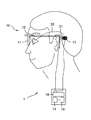
ここで視覚再生補助装置について説明する。図8は視覚再生補助装置の外観図である。図9は体内装置の概略図である。視覚再生補助装置1は、外界(被写体)を撮影する体外装置10と、網膜を構成する細胞に電気刺激を与え視覚の再生を促す体内装置20に大別される。体外装置10は、患者が掛ける眼鏡11と、眼鏡に取り付けられる撮影装置12と、撮影装置12で撮影された被写体画像に基づき電気刺激パルス用データを生成する画像処理部13と、視覚再生補助装置1全体に電力を供給するための電力供給源(電源)14と、電気刺激パルス用データに基づき電源14の電力を変調して電磁波を生成する変調手段16と、変調手段16で生成された電磁波を体内装置20に送信する送信手段(1次コイル)15等で構成されている。送信手段15の中心には磁石(図示を略す)が取り付けられ、磁力で後述する体内装置20側の受信手段21と位置が固定される。
Here, the visual reproduction assisting device will be described. FIG. 8 is an external view of the visual reproduction assisting device. FIG. 9 is a schematic view of an intracorporeal device. The visual
体内装置20は、ケーブル30で接続された受信部20aと刺激部20bを持つ。受信部20aは受信手段21、制御部22、対向電極26を備える。受信手段21は、体外装置10から送信された電磁波を受信する。制御部22は、受信手段21で受信された電磁波を復調して電気刺激パルス用データと電力を得る。なお制御部22で抽出された電力は体内装置20の駆動に使用される他、電極27から出力する刺激電流に用いられる。電気刺激パルス用データは、電極27から刺激電流を出力させる電極指定信号を含む。対向電極26は網膜を挟んで電極27に対向する位置に置かれる。
The
刺激部20bは、基板25、デマルチプレクサ40、電極27を持つ。基板25は眼球の形状に沿って撓る柔軟性を持つ樹脂などで所定厚に形成される。基板27の先端側(開放側)には複数の電極27が形成されている。電極27は、白金等の生体適合性を持つ金属で形成される。また基板27の基端側(ケーブル30の接続側)には、デマルチプレクサ40が搭載されている。デマルチプレクサ40は、刺激電流を各電極27に振り分ける。
The
以上の構成を備える体内装置20は、患者の体内の所定位置に設置される。図10は患者眼Eに刺激部40を設置した一例である。基板25上に形成される電極27を脈絡膜E2に接触させた状態で、基板25の一部を、強膜E3と脈絡膜E2との間に設置する。また、基板25のデマルチプレクサ40が搭載されている範囲は、強膜E3の外側に置く。なお基板25の設置は、強膜E3の一部を切開して始めに強膜ポケットを形成し、強膜ポケット内(脈絡膜E2の外側)に基板25の電極27部分を挿入し、縫合等で基板25を固定する手順で行われる。なお不関電極26は、網膜を挟んで電極27に対向する眼内の位置に置かれる。なお図10では、体内装置20(刺激部40)を強膜E3側に設置させて、強膜側(脈絡側)から網膜E1を構成する細胞を電気刺激する構成としている。これ以外にも、電極27は、患者眼の網膜を構成する細胞を刺激できる位置に設置されれば良い。例えば、体内装置20を患者眼の眼内(網膜上や網膜下)に設置し、電極が形成された基板25を網膜下(網膜と脈絡膜との間)や網膜上に設置しても良い。
The in-
以上のような視覚再生補助装置1の埋植前後の患者に対して、上述のような視機能評価プログラムを備える視機能評価装置を用いて、視機能の検査、視機能の訓練を好適に行うことができるようになる。
For the patients before and after implantation of the visual
1 視覚再生補助装置
10 体外装置
20 体内装置
27 電極
50 制御部
60 表示装置
61 ディスプレイ
62 タッチパネル
70 選択装置
71 ディスプレイ
72 入力部
73 記憶部
74 時間計測装置
80 音声発生装置
100 視機能評価装置
DESCRIPTION OF
Claims (5)
第1表示画面の所定の表示座標に患者に呈示する検査視標を表示させる第1表示制御ステップと、
前記第1表示画面を覆って設置されるタッチパネルから、接触により特定される押圧座標の信号を取得する取得ステップと、
前記表示座標と前記押圧座標の位置関係に基づき音出力手段に音を出力させる音制御ステップと、
をコンピュータに実行させることを特徴とする視機能評価プログラム。 A visual function evaluation program for examining or training a patient's visual function,
A first display control step for displaying an examination target to be presented to the patient at predetermined display coordinates on the first display screen;
An acquisition step of acquiring a signal of a press coordinate specified by contact from a touch panel installed covering the first display screen;
A sound control step for causing the sound output means to output a sound based on the positional relationship between the display coordinates and the pressed coordinates;
A visual function evaluation program characterized by causing a computer to execute the above.
前記音制御ステップは、前記演算ステップにおける演算結果に基づき前記音出力手段から出力する音を制御する請求項1の視機能評価プログラム。 Causing the computer to further perform a calculation step for obtaining a positional relationship between the display coordinates and the pressed coordinates;
The visual function evaluation program according to claim 1, wherein the sound control step controls a sound output from the sound output unit based on a calculation result in the calculation step.
第1表示画面の所定の表示座標に患者に呈示する検査視標を表示させる第1表示制御手段と、
前記第1表示画面を覆って設置されるタッチパネルから、接触により特定される押圧座標の信号を取得する取得手段と、
前記表示座標と前記押圧座標の位置関係に基づき音出力手段に音を出力させる音制御手段と、
を備えたことを特徴とする視機能評価装置。 A visual function evaluation apparatus for examining or training a visual function of a patient,
First display control means for displaying an examination target to be presented to the patient at predetermined display coordinates on the first display screen;
An acquisition means for acquiring a signal of a press coordinate specified by contact from a touch panel installed covering the first display screen;
Sound control means for outputting sound to the sound output means based on the positional relationship between the display coordinates and the pressed coordinates;
A visual function evaluation apparatus comprising:
Priority Applications (1)
| Application Number | Priority Date | Filing Date | Title |
|---|---|---|---|
| JP2012260735A JP6128814B2 (en) | 2012-11-29 | 2012-11-29 | Visual function evaluation program and visual function evaluation apparatus |
Applications Claiming Priority (1)
| Application Number | Priority Date | Filing Date | Title |
|---|---|---|---|
| JP2012260735A JP6128814B2 (en) | 2012-11-29 | 2012-11-29 | Visual function evaluation program and visual function evaluation apparatus |
Publications (3)
| Publication Number | Publication Date |
|---|---|
| JP2014104244A JP2014104244A (en) | 2014-06-09 |
| JP2014104244A5 JP2014104244A5 (en) | 2016-01-21 |
| JP6128814B2 true JP6128814B2 (en) | 2017-05-17 |
Family
ID=51026225
Family Applications (1)
| Application Number | Title | Priority Date | Filing Date |
|---|---|---|---|
| JP2012260735A Active JP6128814B2 (en) | 2012-11-29 | 2012-11-29 | Visual function evaluation program and visual function evaluation apparatus |
Country Status (1)
| Country | Link |
|---|---|
| JP (1) | JP6128814B2 (en) |
Families Citing this family (3)
| Publication number | Priority date | Publication date | Assignee | Title |
|---|---|---|---|---|
| KR101451669B1 (en) | 2014-06-12 | 2014-10-17 | (주) 뷰엠테크놀로지 | Automatic eyesight examination apparatus and automatic eyesight examination method |
| JP6409243B2 (en) * | 2014-08-15 | 2018-10-24 | 学校法人立命館 | Laboratory animal visual function evaluation system |
| JP2017143992A (en) * | 2016-02-16 | 2017-08-24 | 株式会社トプコン | Ophthalmologic examination system and ophthalmologic examination apparatus |
Family Cites Families (8)
| Publication number | Priority date | Publication date | Assignee | Title |
|---|---|---|---|---|
| JPS58142006U (en) * | 1982-03-18 | 1983-09-24 | 株式会社堀場製作所 | vision recovery training device |
| KR100387356B1 (en) * | 1998-07-16 | 2003-08-25 | 주식회사 다물시스텍 | Visual inspection method using screen |
| JP2000116600A (en) * | 1998-10-09 | 2000-04-25 | Canon Inc | Vision instrument |
| JP4901009B2 (en) * | 2001-03-02 | 2012-03-21 | 興和株式会社 | Perimeter |
| JP4938322B2 (en) * | 2006-03-09 | 2012-05-23 | 株式会社トプコン | Input device and subjective optometry device |
| JP2009072285A (en) * | 2007-09-19 | 2009-04-09 | Topcon Corp | Optometer |
| US8136943B2 (en) * | 2009-07-09 | 2012-03-20 | Nike, Inc. | Testing/training visual perception speed and/or span |
| JP5643004B2 (en) * | 2010-06-10 | 2014-12-17 | 株式会社ニデック | Ophthalmic equipment |
-
2012
- 2012-11-29 JP JP2012260735A patent/JP6128814B2/en active Active
Also Published As
| Publication number | Publication date |
|---|---|
| JP2014104244A (en) | 2014-06-09 |
Similar Documents
| Publication | Publication Date | Title |
|---|---|---|
| US7908011B2 (en) | Visual prosthesis fitting | |
| JP4484523B2 (en) | Method and system for assessing eye disease | |
| KR101754367B1 (en) | Unified vision testing and/or training | |
| US8066376B2 (en) | Dynamic shape discrimination vision test | |
| JP2001509693A (en) | Visual field inspection method and apparatus | |
| CN107592798A (en) | Method and apparatus for determining user's eyesight | |
| US20140066802A1 (en) | Cognition and Usability Aptitude Evaluations for Clinician Programmers | |
| JPH03500015A (en) | Method and apparatus for measuring retinal response | |
| JP6128814B2 (en) | Visual function evaluation program and visual function evaluation apparatus | |
| US10576270B2 (en) | Tongue stimulation for communication of information to a user | |
| CN105326471A (en) | Children visual acuity testing device and testing method | |
| Fornos et al. | Simulation of artificial vision: IV. Visual information required to achieve simple pointing and manipulation tasks | |
| WO2003017256A1 (en) | Method for establishing fixation employing speech recognition | |
| US11337605B2 (en) | Simulator for the evaluation of a concussion from signs displayed during a visual cranial nerve assessment | |
| JP5118777B1 (en) | Peripheral nerve examination device | |
| KR20170087863A (en) | Method of testing an infant and suitable device for implementing the test method | |
| JP2014100270A (en) | Ultrasound image device | |
| CN111084931A (en) | Implantable spinal cord stimulation system and information recording and adjusting method thereof | |
| TWI796222B (en) | Visual spatial-specific response time evaluation system and method based on immersive virtual reality device | |
| KR102570392B1 (en) | Method and apparatus for measuring refractive error | |
| Gebrehiwot | Developing Computer-Brain Interfaces to Target Cortical Areas of the Human Brain to Augment Sensory Information | |
| KR20120012616A (en) | Apparatus and method for simulating pulse |
Legal Events
| Date | Code | Title | Description |
|---|---|---|---|
| A521 | Request for written amendment filed |
Free format text: JAPANESE INTERMEDIATE CODE: A523 Effective date: 20151127 |
|
| A621 | Written request for application examination |
Free format text: JAPANESE INTERMEDIATE CODE: A621 Effective date: 20151127 |
|
| A131 | Notification of reasons for refusal |
Free format text: JAPANESE INTERMEDIATE CODE: A131 Effective date: 20160823 |
|
| A977 | Report on retrieval |
Free format text: JAPANESE INTERMEDIATE CODE: A971007 Effective date: 20160824 |
|
| A521 | Request for written amendment filed |
Free format text: JAPANESE INTERMEDIATE CODE: A523 Effective date: 20161019 |
|
| TRDD | Decision of grant or rejection written | ||
| A01 | Written decision to grant a patent or to grant a registration (utility model) |
Free format text: JAPANESE INTERMEDIATE CODE: A01 Effective date: 20170314 |
|
| A61 | First payment of annual fees (during grant procedure) |
Free format text: JAPANESE INTERMEDIATE CODE: A61 Effective date: 20170411 |
|
| R150 | Certificate of patent or registration of utility model |
Ref document number: 6128814 Country of ref document: JP Free format text: JAPANESE INTERMEDIATE CODE: R150 |
|
| R250 | Receipt of annual fees |
Free format text: JAPANESE INTERMEDIATE CODE: R250 |
|
| R250 | Receipt of annual fees |
Free format text: JAPANESE INTERMEDIATE CODE: R250 |
|
| R250 | Receipt of annual fees |
Free format text: JAPANESE INTERMEDIATE CODE: R250 |
|
| R250 | Receipt of annual fees |
Free format text: JAPANESE INTERMEDIATE CODE: R250 |
|
| R250 | Receipt of annual fees |
Free format text: JAPANESE INTERMEDIATE CODE: R250 |