JP6127627B2 - Optimizing optical network simulation - Google Patents
Optimizing optical network simulation Download PDFInfo
- Publication number
- JP6127627B2 JP6127627B2 JP2013058270A JP2013058270A JP6127627B2 JP 6127627 B2 JP6127627 B2 JP 6127627B2 JP 2013058270 A JP2013058270 A JP 2013058270A JP 2013058270 A JP2013058270 A JP 2013058270A JP 6127627 B2 JP6127627 B2 JP 6127627B2
- Authority
- JP
- Japan
- Prior art keywords
- optical signal
- transmission path
- polarization state
- signal transmission
- optical
- Prior art date
- Legal status (The legal status is an assumption and is not a legal conclusion. Google has not performed a legal analysis and makes no representation as to the accuracy of the status listed.)
- Active
Links
Images


Classifications
-
- H—ELECTRICITY
- H04—ELECTRIC COMMUNICATION TECHNIQUE
- H04B—TRANSMISSION
- H04B10/00—Transmission systems employing electromagnetic waves other than radio-waves, e.g. infrared, visible or ultraviolet light, or employing corpuscular radiation, e.g. quantum communication
- H04B10/27—Arrangements for networking
Description
本稿で論じる実施形態は光ネットワーク設計に関する。 The embodiments discussed herein relate to optical network design.
光ネットワークは世界中でデータを送信するために設置されている。光ネットワークの増え続けるデータ・スループット要求のため、光ネットワーク内のデータ・レートも増大し続けてきた。光ネットワーク内のデータ・レートを増大させる一つの方法は、光信号によって担持されるデータの量を増すことである。たとえば、光信号の単純な振幅変調を実行する代わりに、光信号の各偏光成分がデータで変調されてもよい。光信号の各偏光成分を変調することによって、データ・レートは、光信号の振幅を単に変調するのに比べて二倍になりうる。 Optical networks are installed to transmit data around the world. Due to the ever-increasing data throughput demands of optical networks, data rates within optical networks have also continued to increase. One way to increase the data rate in an optical network is to increase the amount of data carried by the optical signal. For example, instead of performing simple amplitude modulation of the optical signal, each polarization component of the optical signal may be modulated with data. By modulating each polarization component of the optical signal, the data rate can be doubled compared to simply modulating the amplitude of the optical signal.
既存の光ネットワークが追加的な変調フォーマットをサポートするようアップグレードされ、新たな光ネットワークが構築されるにつれて、光ネットワーク内の光信号の正確な伝送品質を保証するためには、光ネットワーク設計の理解が不可欠となっている。光ネットワーク設計の不可欠な構成要素は、光ネットワークの伝送特性のモデル化でありうる。光ネットワークの伝送特性のモデル化は、色分散、非線形効果、偏光効果その他といった伝送劣化因子がいかに光ネットワーク内の光信号に影響しうるかに対する洞察を提供する。特に、より高いデータ・レートにおいては、これらの劣化因子間の相互作用が特に重要となることがある。こうした劣化因子を正確にモデル化することは、光モデル化システムを使った数千ものシミュレーションを必要とすることがあり、その結果、モデル化時間が長大になる。 As existing optical networks are upgraded to support additional modulation formats and new optical networks are built, an understanding of optical network design to ensure the correct transmission quality of optical signals within the optical network Is indispensable. An essential component of optical network design can be the modeling of the transmission characteristics of the optical network. Modeling the transmission characteristics of an optical network provides insight into how transmission degradation factors such as chromatic dispersion, nonlinear effects, polarization effects, etc. can affect optical signals in the optical network. In particular, at higher data rates, the interaction between these degradation factors may be particularly important. Accurate modeling of these degradation factors can require thousands of simulations using an optical modeling system, resulting in a long modeling time.
本願で請求される主題は、何らかの欠点を解決する実施形態や上記のような環境でのみ動作する実施形態に限定されるものではない。むしろ、上記の背景は、本稿に記載されるいくつかの実施形態が実施されうる一つの例示的な技術分野を例解するために与えられているものである。 The subject matter claimed herein is not limited to embodiments that solve any disadvantages or that operate only in environments such as those described above. Rather, the above background is provided to illustrate one exemplary technology area in which some embodiments described herein may be implemented.
ある実施形態のある側面によれば、光信号伝送経路をモデル化する方法が、光ネットワークのパラメータおよび光信号伝送経路内の光信号の偏光状態をランダムに変化させることに基づいて光ネットワーク内の光信号伝送経路の第一の伝送特性を取得することを含んでいてもよい。本方法はまた、前記パラメータおよび前記光信号の第一の固定した偏光状態に基づいて前記光信号伝送経路の第二の伝送特性を取得することを含んでいてもよい。本方法はまた、前記第一の伝送特性と前記第二の伝送特性との相関を調べて、前記光信号の有効偏光状態を取得することを含んでいてもよい。前記パラメータおよび前記光信号の有効偏光状態に基づく前記光信号伝送経路のシミュレーションは、前記第一の伝送特性を近似しうる伝送特性を生成しうる。 According to one aspect of an embodiment, a method for modeling an optical signal transmission path is based on randomly changing an optical network parameter and a polarization state of an optical signal in the optical signal transmission path. Obtaining a first transmission characteristic of the optical signal transmission path may be included. The method may also include obtaining a second transmission characteristic of the optical signal transmission path based on the parameter and a first fixed polarization state of the optical signal. The method may also include examining a correlation between the first transmission characteristic and the second transmission characteristic to obtain an effective polarization state of the optical signal. The simulation of the optical signal transmission path based on the parameters and the effective polarization state of the optical signal can generate a transmission characteristic that can approximate the first transmission characteristic.
実施形態の目的および利点は、少なくとも、請求項において具体的に指摘されている要素、特徴および組み合わせによって認識され、達成されるであろう。 The objects and advantages of the embodiments will be realized and attained by at least the elements, features and combinations particularly pointed out in the claims.
上記の概括的な記載および以下の詳細な説明はいずれも例示的かつ説明用のものであって、請求項に記載される発明を制約するものではないことは理解しておくものとする。 It is to be understood that both the foregoing general description and the following detailed description are exemplary and explanatory and are not restrictive of the invention as claimed.
例示的な実施形態が、付属の図面を使って、さらなる具体性および詳細さで記載され、説明される。
本稿に記載されるいくつかの実施形態は、光ネットワーク内の光信号伝送経路をモデル化する方法を含んでいてもよい。特に、本稿に記載されるいくつかの実施形態は、従来技術により光信号伝送経路をモデル化するシミュレーションの数に比べて、光信号伝送経路をモデル化するためのシミュレーションの数を減らす、光信号伝送経路をモデル化する方法を含んでいてもよい。 Some embodiments described herein may include a method for modeling an optical signal transmission path in an optical network. In particular, some embodiments described herein reduce the number of simulations for modeling optical signal transmission paths compared to the number of simulations for modeling optical signal transmission paths according to the prior art. A method for modeling a transmission path may be included.
いくつかの従来技術では、光信号が光信号伝送経路を進む際の光信号の偏光状態のランダムな回転のため、光ネットワーク内の光信号伝送経路の劣化因子を正確にモデル化するためには数千または数万のシミュレーションが実行される。光信号伝送経路をモデル化するためのシミュレーションの数を減らすため、光信号伝送経路をモデル化する方法は、光ネットワークのあるパラメータおよび光信号伝送経路内の光信号の偏光状態をランダムに変化させることに基づいて光ネットワークの光信号伝送経路の第一の伝送特性を取得することを含んでいてもよい。本方法はまた、前記パラメータおよび前記光信号の第一の固定した偏光状態に基づいて前記光信号伝送経路の第二の伝送特性を取得することを含んでいてもよい。前記第一の伝送特性は前記第二の伝送特性との相関を調べられて、前記パラメータおよび前記光信号の有効偏光状態に基づく前記光信号伝送経路のシミュレーションが、前記第一の伝送特性を近似するよう、前記光信号の有効偏光状態が得られる。 In some prior arts, due to the random rotation of the polarization state of the optical signal as it travels along the optical signal transmission path, in order to accurately model the degradation factors of the optical signal transmission path in the optical network Thousands or tens of thousands of simulations are performed. In order to reduce the number of simulations for modeling the optical signal transmission path, the method of modeling the optical signal transmission path randomly changes certain parameters of the optical network and the polarization state of the optical signal in the optical signal transmission path. And obtaining the first transmission characteristic of the optical signal transmission path of the optical network. The method may also include obtaining a second transmission characteristic of the optical signal transmission path based on the parameter and a first fixed polarization state of the optical signal. The first transmission characteristic is examined for correlation with the second transmission characteristic, and the simulation of the optical signal transmission path based on the parameter and the effective polarization state of the optical signal approximates the first transmission characteristic. Thus, an effective polarization state of the optical signal is obtained.
光信号の有効偏光状態を使うことは、二桁ないし三桁少ないシミュレーションを実行することによる光ネットワークの正確なモデル化を許容しうる。たとえば、いくつかの実施形態では、普通なら数千または数万回のシミュレーションを必要とする結果を得るために、十回またはそれ未満のシミュレーションが、光信号の有効偏光状態を使って実行されてもよい。 Using the effective polarization state of the optical signal may allow accurate modeling of the optical network by performing a simulation that is two or three orders of magnitude less. For example, in some embodiments, ten or fewer simulations are performed using the effective polarization state of the optical signal to obtain results that would normally require thousands or tens of thousands of simulations. Also good.
本発明の実施形態について、付属の図面を参照して説明する。 Embodiments of the present invention will be described with reference to the accompanying drawings.
図1は、本稿に記載される少なくともいくつかの実施形態に基づいて構成された、例示的な光ネットワーク100のブロック図である。光ネットワーク100は、光ネットワーク100のコンポーネントによって通信される一つまたは複数の光信号を転送するよう構成された光ファイバー140を含んでいてもよい。光ファイバー140によって結合された光ネットワーク100のコンポーネントは、末端ノード110a、110bおよび光ノード130を含んでいてもよい。光ネットワーク100は末端ノード110a、110bをもつポイントツーポイントの光ネットワークとして図示されているが、光ネットワーク100はリング光ネットワーク、メッシュ光ネットワークまたは他の任意の光ネットワークまたはネットワークの組み合わせとして構成されてもよい。光ネットワーク100は、短距離(short-haul)ネットワーク、長距離(long-haul)ネットワークまたは他の任意の光ネットワークまたは光ネットワークの組み合わせとして使われてもよい。光ファイバー140は、中でもシングルモード・ファイバー(SMF: Single-Mode Fiber)、向上大有効面積ファイバー(E-LEAF: Enhanced Large Effective Area Fiber)、分散補償ファイバー(DCF: Dispersion Compensating Fiber)、マルチモード・ファイバー(MMF: Multi-Mode Fiber)およびそれらの組み合わせのような任意の好適な型の光ファイバーを含みうる。
FIG. 1 is a block diagram of an exemplary
末端ノード110aは、一つまたは複数のトランシーバ112、マルチプレクサ114および増幅器116を含んでいてもよい。各トランシーバ112は、データをエンコードするために光信号を変調し、該光信号を光ネットワーク100内で送信するよう構成された任意の型のトランシーバを含みうる。トランシーバ112によって送信された光信号のそれぞれは、異なる特定の波長を中心としていてもよく、波長チャネルと称されてもよい。マルチプレクサ114は、トランシーバ112からの複数の波長チャネルを多重化信号に組み合わせて、該多重化信号を光ファイバー140中に送信してもよい。たとえば、マルチプレクサ114は波長選択性スイッチ(WSS: wavelength selective switch)を含んでいてもよい。増幅器116は、多重化信号を増幅するよう構成されていてもよく、いくつかの実施形態では、光リピーターを含んでいてもよい。
The
光ノード130は増幅器132、光分散補償モジュール(DCM: dispersion compensating module)134および挿入/分岐モジュール(ADM: add/drop module)136を含んでいてもよい。増幅器132は増幅器116と同様であってもよく、多重化信号を増幅するよう構成されていてもよい。DCM 134は多重化信号内でデータを担持する一つまたは複数の波長チャネルに対して光分散補償を実行するよう構成されていてもよい。ADM 136は、多重化信号内でデータを担持する波長チャネルを挿入または分岐するとともに、波長チャネルの一つまたは複数の光分散を補償するよう構成されていてもよい。
The
末端ノード110bは、トランシーバ122、デマルチプレクサ120、増幅器124およびDCM 126を含んでいてもよい。増幅器124は、多重化信号を増幅するよう構成されていてもよく、いくつかの実施形態では、光リピーターを含んでいてもよい。DCM 126は多重化信号の一つまたは複数の波長チャネルに対して光分散補償を実行するよう構成されていてもよい。デマルチプレクサ120は、増幅器124および/またはDCM 126から受け取った増幅された多重化信号を、別個の波長チャネルに分離するよう構成されていてもよい。各波長チャネルは諸トランシーバ122のうちの対応するものに渡されてもよい。たとえば、デマルチプレクサ120は波長選択性スイッチ(WSS)を含んでいてもよい。各トランシーバ122は、対応する波長チャネルを受信し、それを復調して電気信号にするよう構成された任意の型のトランシーバを含みうる。いくつかの実施形態では、トランシーバ122は、デジタル信号処理を含むコヒーレントな受信機(coherent receiver)であってもよい。
The
いくつかの実施形態では、図のような光ネットワーク100は、末端ノード110a、110bの間に延在し、これらを含む光信号伝送経路であってもよい。他の実施形態では、光ネットワーク100内の光信号伝送経路は末端ノード110aと光ノード130の一つとの間に延在していてもよい。光ネットワーク100は、一つまたは複数の光信号伝送経路を含む例示的な光ネットワークとして例示されているのであり、限定するべきではない。いくつかの実施形態では、光ネットワーク100は二つより多くまたは二つより少ない光ノード130を含んでいてもよい。代替的または追加的に、光ノード130は、図1に示したもの以外の構成要素を含んでいてもよい。さらに、いくつかの実施形態では、末端ノード110a、110bは図1に示したもの以外の構成要素を含んでいてもよい。代替的または追加的に、末端ノード110a、110bはいずれも、光ネットワーク100を通じて光信号を受信および送信するよう構成されていてもよい。
In some embodiments, an
光ネットワーク100は、光ネットワークの光モデル化(optical modeling)を論じるときに例示的な光ネットワークとして使用されうる。光ネットワークの光モデル化は、光ネットワークにおける光信号伝送経路の伝送特性を決定することを含んでいてもよい。光信号伝送経路の伝送特性は、色分散(CD: chromatic dispersion)、非線形(NL: nonlinear)効果、偏光モード分散(PMD: polarization mode dispersion)および変更依存性損失(PDL: polarization dependent loss)のような偏光効果、増幅された自発放射(ASE: amplified spontaneous emission)その他といった伝送劣化因子がいかに光信号伝送経路に沿った光信号に影響しうるかに対する洞察を提供する。たとえば、光ネットワーク100の光モデル化は、増幅器116、132、124、ADM 136、DCM 134、光ファイバー140およびその他のコンポーネントといった光ネットワーク100内のさまざまな構成要素がどのように光ネットワーク100内の光信号伝送経路に沿って伝送される光信号の伝送劣化につながるかに対する洞察を提供しうる。特に、光ネットワーク100内の光信号伝送経路の光モデル化は、種々の伝送劣化因子の個別的な型がどのように光信号の伝送劣化につながるかに対する洞察を提供しうる。
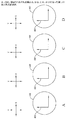
上記のように、伝送劣化因子は、光信号の信号劣化につながりうる。光信号の劣化は、光信号対雑音比(OSNR: optical signal to noise ratio)ペナルティーとして表現されてもよい。よって、個別的な劣化因子に起因する光信号の劣化は、その劣化因子のOSNRペナルティーと称されてもよい。たとえば、PDLに起因する光信号の劣化は、PDL OSNRペナルティーと称されてもよい。光信号のOSNRを低下させることのほか、劣化因子は、光信号に対して他の効果をもつこともある。たとえば、ファイバー複屈折が、光信号の偏光状態をランダムに回転させることがある。光信号の偏光状態のランダムな回転は、結果としてPDLのランダムな蓄積(accumulation)につながる。PDLは、PDLの軸と光信号の偏光の軸との間の配向または角度に基づいて蓄積するからである。状況によっては、特により高いデータ・レート、たとえば毎秒40ギガビットまたはそれ以上のデータ・レートでは、PDLは、NL効果のような他の信号劣化因子から寄与されるOSNRペナルティーの量に影響しうる。図2のAおよびBは、本稿に記載される少なくともいくつかの実施形態に基づいて構成される、光信号210およびPDL 220の例示的な成分を示している。光信号210は第一および第二の偏光成分212、214を有していてもよい。同様に、PDL 220は第一および第二の偏光成分222、224を有していてもよい。図2のAに示されるように、光信号210およびPDL 220は、デカルト座標系のx軸およびy軸に関して配向されていてもよい。光信号210およびPDL 220の第一の成分212、222はy軸に沿って配向されていてもよく、光信号210およびPDL 220の第二の成分214、224はx軸に沿って配向されていてもよい。
As described above, the transmission degradation factor can lead to signal degradation of the optical signal. The degradation of the optical signal may be expressed as an optical signal to noise ratio (OSNR) penalty. Therefore, the degradation of the optical signal due to an individual degradation factor may be referred to as an OSNR penalty for the degradation factor. For example, optical signal degradation due to PDL may be referred to as a PDL OSNR penalty. In addition to reducing the OSNR of the optical signal, the degradation factor may have other effects on the optical signal. For example, fiber birefringence can randomly rotate the polarization state of the optical signal. Random rotation of the polarization state of the optical signal results in random accumulation of PDL. This is because the PDL accumulates based on the orientation or angle between the axis of the PDL and the axis of polarization of the optical signal. In some situations, particularly at higher data rates, eg, 40 gigabits per second or higher, PDL can affect the amount of OSNR penalty contributed by other signal degradation factors such as the NL effect. 2A and 2B illustrate exemplary components of an
光信号の偏光状態は、光信号210の第一および第二の偏光成分212、214の間の関係ならびに第一および第二の偏光成分212、214の互いに対するおよび光信号210の伝搬方向に対する配向を示す。少なくともいくつかの偏光状態では、光信号210の偏光状態をランダムに回転させることは、第一および第二の偏光成分212、214がxy平面内でランダムに回転し、それにより第一および第二の偏光成分212、214がそれぞれy軸およびx軸と整列しなくなることを示す。光信号210のランダム回転は左に行われても右に行われてもよく、さまざまな量の回転が行われてもよい。
The polarization state of the optical signal depends on the relationship between the first and
図2のBは、第一および第二の偏光成分212、214がそれぞれy軸およびx軸と整列しなくなるよう回転された光信号210を示す。光信号210が回転するとき、光信号210は光信号210の偏光軸とPDL 220の軸との間の角230をなす。光信号210の偏光軸とPDL 220との間の角230は、本稿では光信号210のPDL角と称されることがある。図2のBに示されるような光信号210の偏光軸とPDL 220の軸との間の角230は45度である。この角230は単に例解のために示されている。角230は、光信号210が光信号伝送経路を進む際にランダムに回転されるので、変わりうる。
FIG. 2B shows the
図3は、本稿に記載される少なくともいくつかの実施形態に基づいて構成された、光信号伝送経路の伝送特性をモデル化する例示的なシステム300のブロック図である。システム300は経路計算エンジン306、データベース330、パラメータ・モジュール340、プロセッサ350、メモリ360およびインターフェース・モジュール370を含んでいてもよい。
FIG. 3 is a block diagram of an
インターフェース・モジュール370は、モデル化されるべき光ネットワーク内の光信号伝送経路に関するデータを受領するよう構成されていてもよい。たとえば、いくつかの実施形態では、インターフェース・モジュール370は、人とのインターフェースをもち、光信号伝送経路についてのデータを受け取るよう構成されていてもよい。代替的または追加的に、インターフェース・モジュール370は、ある装置からその光信号伝送経路についてのデータを受け取るよう構成されていてもよい。インターフェース・モジュール370は、中でもファイバー型;ファイバー長;光信号伝送経路におけるDCM、ADM、増幅器、マルチプレクサまたはデマルチプレクサのようなコンポーネントの数および/または型;データ・レート;データの変調フォーマット;光信号の入力パワー;本稿でチャネルと称されることのある信号を担持する波長の数;チャネル間隔;トラフィック需要;ネットワーク・トポロジーといった、光信号伝送経路についてのデータを受け取ってもよい。
The
インターフェース・モジュール370は、光信号伝送経路についてのデータを人から受け取るおよび/またはシミュレーション結果を人に対して出力することを容易にするための一つまたは複数の入力装置および/または出力装置を含んでいてもよいし、および/またはそのような入力装置および/または出力装置に結合されていてもよい。一つまたは複数の入力および/または出力装置は、これに限られないが、キーボード、マウス、タッチパッド、マイクロホン、ディスプレイ、タッチスクリーン・ディスプレイ、オーディオ・スピーカーなどを含んでいてもよいが、これに限定されない。
The
パラメータ・モジュール340は、光信号伝送経路について受け取られたデータに基づいて光信号伝送経路に関するパラメータを提供するよう構成されていてもよい。たとえば、パラメータ・モジュール340は、ファイバー型に関するパラメータ、たとえばファイバー型についての分散マップ(dispersion map)およびファイバー型の他の光学的属性を提供してもよい。もう一つの例として、パラメータ・モジュール340は、光信号伝送経路中のコンポーネントに関するパラメータを提供してもよい。たとえば、パラメータ・モジュール340によって提供されるかかるコンポーネントのパラメータは、コンポーネントのPDLおよびコンポーネントの他の光学的属性を含んでいてもよい。本質的には、パラメータ・モジュール340は、光信号伝送経路をモデル化するために経路計算エンジン306が使用することがありうる光信号伝送経路中のコンポーネントの光学的属性の一部または全部を提供してもよい。
The
経路計算エンジン306はパラメータ・モジュール340からのパラメータおよびインターフェース・モデル370からのデータを、光信号伝送経路の伝送特性を決定するために使うよう構成されていてもよい。光信号伝送経路の伝送特性は、色分散(CD: chromatic dispersion)、非線形(NL: nonlinear)効果、偏光モード分散(PMD: polarization mode dispersion)および変更依存性損失(PDL: polarization dependent loss)のような偏光効果、増幅された自発放射(ASE: amplified spontaneous emission)および/またはその他といった伝送劣化因子がいかに光信号伝送経路内の光信号に影響しうるかに対する洞察を提供してもよい。光信号伝送経路の伝送特性を決定するために、経路計算エンジン306は、伝送劣化因子間の相互作用を考慮してもよい。
The path calculation engine 306 may be configured to use the parameters from the
いくつかの実施形態では、経路計算エンジン306は、光信号伝送経路についての各伝送劣化因子の蓄積された量を提供してもよい。代替的または追加的に、経路計算エンジン306は、各伝送劣化因子に起因するOSNRペナルティーを提供してもよい。代替的または追加的に、経路計算エンジン306は、一つまたは複数の伝送劣化因子の組み合わせに起因するOSNRペナルティーを提供してもよい。たとえば、いくつかの実施形態では、組み合わされたNLおよびPDL OSNRペナルティーが、別個に決定されたNL OSNRペナルティーおよびPDL OSNRペナルティーの組み合わせより高いことがある。組み合わされたNLおよびPDL OSNRペナルティーは、光信号伝送経路におけるNL効果とPDL効果の間の相互作用を考慮に入れることができるからである。代替的または追加的に、経路計算エンジン306は、光信号伝送経路の総OSNRを提供してもよい。総OSNRは、何ら劣化なしにその光信号伝送経路に沿って達成されうる最適なOSNRであってもよい。いくつかの実施形態では、経路計算エンジン306は、光信号伝送経路に関する追加的な情報を提供してもよい。 In some embodiments, the path calculation engine 306 may provide a stored amount of each transmission degradation factor for the optical signal transmission path. Alternatively or additionally, the path calculation engine 306 may provide an OSNR penalty due to each transmission degradation factor. Alternatively or additionally, the path calculation engine 306 may provide an OSNR penalty due to a combination of one or more transmission degradation factors. For example, in some embodiments, the combined NL and PDL OSNR penalty may be higher than a separately determined combination of NL OSNR penalty and PDL OSNR penalty. This is because the combined NL and PDL OSNR penalty can take into account the interaction between the NL and PDL effects in the optical signal transmission path. Alternatively or additionally, the path calculation engine 306 may provide the total OSNR of the optical signal transmission path. The total OSNR may be the optimal OSNR that can be achieved along the optical signal transmission path without any degradation. In some embodiments, the path calculation engine 306 may provide additional information regarding the optical signal transmission path.
データベース330は、光信号伝送経路について経路計算エンジン306によって生成されたデータを記憶するよう構成されていてもよい。プロセッサ350は、システム300に本稿に記載される機能および動作を実行させるコンピュータ命令を実行するよう構成されていてもよい。コンピュータ命令はプロセッサ350による実行のためにメモリ360にロードされてもよく、および/または、本稿に記載される機能および動作の実行の際に生成、受領または操作されるデータが少なくとも一時的にメモリ360に記憶されてもよい。
光信号伝送経路中の光信号のランダムに回転する偏光状態に起因する光信号伝送経路の伝送特性のいくつかを正確にシミュレートするためには、経路計算エンジン306は、光信号伝送経路の伝送特性を決定するために、光信号の変化する偏光状態を使って少なくとも千回のシミュレーションを実行することがある。特に、PDLおよびNL効果のような伝送特性およびPDLおよびNL効果の間の相互作用をシミュレートするためには、経路計算306は、光信号の変化する偏光状態を使って少なくとも千回のシミュレーションを実行することがある。いくつかの実施形態では、システム300は、組み合わされたNLおよびPDL OSNRペナルティーを決定してもよい。これは、PDL効果、NL効果およびPDLおよびNL効果の間の相互作用を考慮に入れてもよい。システム300は代替的に、光信号伝送経路のPDLおよびNL効果およびPDLおよびNL効果の間の相互作用のような伝送特性を近似するために、光信号の有効偏光状態(effective state of polarization)を使ってもよい。有効偏光状態は、経路計算エンジン306に、光信号伝送経路の伝送特性を近似するために光信号の固定偏光状態を使って十回またはそれ未満のシミュレーションを実行することを許容する。特に、有効偏光状態は、経路計算エンジン306が、光信号伝送経路のPDLおよびNL効果の間の相互作用を近似することを許容する。端的に言うと、有効偏光状態は、シミュレートされるときに、光信号のランダムに変化する偏光状態をシミュレートすることから帰結する伝送特性を生成する、光信号の固定した偏光状態である。
In order to accurately simulate some of the transmission characteristics of the optical signal transmission path due to the randomly rotating polarization state of the optical signal in the optical signal transmission path, the path calculation engine 306 performs transmission of the optical signal transmission path. To determine the characteristics, at least a thousand simulations may be performed using the changing polarization state of the optical signal. In particular, to simulate transmission characteristics such as the PDL and NL effects and the interaction between the PDL and NL effects, the path calculator 306 performs at least a thousand simulations using the changing polarization state of the optical signal. May be executed. In some embodiments, the
有効偏光状態は、光信号伝送経路の異なる型については異なっていてもよい。特に、有効偏光状態は、光信号伝送経路内の異なるパラメータについては異なっていてもよい。たとえば、有効偏光状態は、光信号伝送経路の種々のファイバー型、変調フォーマットおよび/または分散特性について決定されてもよい。 The effective polarization state may be different for different types of optical signal transmission paths. In particular, the effective polarization state may be different for different parameters in the optical signal transmission path. For example, the effective polarization state may be determined for various fiber types, modulation formats and / or dispersion characteristics of the optical signal transmission path.
特定のパラメータを用いて光信号伝送経路についての有効偏光状態を決定するために、光信号伝送経路のモデルが、経路計算エンジン306によるシミュレーションのための該特定のパラメータを用いて生成されてもよい。光信号伝送経路についての有効偏光状態の決定について、下記で図3、図4、図5のA〜D、図6のA〜Dおよび図7を参照して論じる。 In order to determine an effective polarization state for an optical signal transmission path using specific parameters, a model of the optical signal transmission path may be generated using the specific parameters for simulation by the path calculation engine 306. . The determination of the effective polarization state for the optical signal transmission path is discussed below with reference to FIGS. 3, 4, 5A-D, 6A-D, and FIG.
図4は、本稿に記載される少なくともいくつかの実施形態に基づいて構成される、例示的なモデル化された光信号伝送経路のブロック図である。モデル化された光信号伝送経路400は、光ファイバー440で相互接続されたモデル化された光ノード410、412、414、416を含む。モデル化された光ノード410、412、414、416は、図1に示される光ネットワーク100中の末端ノード110a、110bおよび光ノード130のような、光ネットワーク中のノードをモデル化するための特性を表すまたはもつのでもよい。
FIG. 4 is a block diagram of an exemplary modeled optical signal transmission path configured in accordance with at least some embodiments described herein. Modeled optical
図3〜図4を合わせて参照するに、経路計算エンジン306は、光信号のランダムに変化する偏光状態を用いてモデル化された光信号伝送経路400に対して複数のシミュレーションを実行するよう構成されていてもよい。たとえば、いくつかの実施形態では、経路計算エンジン306は、モデル化された光信号伝送経路400の1000回、5000回、10000回またはそれ以上のシミュレーションを実行してもよい。モデル化された光信号伝送経路400内の光信号のランダムに変化する偏光状態をシミュレートするために、経路計算エンジン306は、シミュレーションの間に、モデル化された光信号伝送経路400内の種々の位置において種々の配向に、光信号をランダムに回転させてもよい。あるシミュレーションの間に回転される光信号の例示的な配向は図5のA〜Dに関して示されている。
3-4 together, the path calculation engine 306 is configured to perform multiple simulations on the optical
図5のA〜Dは、本稿に記載される少なくともいくつかの実施形態に基づいて構成される、図4のそれぞれ直線A-A、B-B、C-C、D-Dに沿った第一の例示的な断面図を示している。図4の直線A-Aでは、図5のAに示されるように、光ファイバー440内の光信号520は、光信号520の成分が、描かれているデカルト座標系のx軸およびy軸と整列されるよう配向されていてもよい。図4の直線B-Bでは、図5のBに示されるように、光信号520は、光信号520の成分がもはや描かれているデカルト座標系の軸と整列されないようxy平面内で回転されていてもよい。
5A-D are first exemplary cross-sectional views taken along lines AA, BB, CC, DD, respectively, of FIG. 4 configured in accordance with at least some embodiments described herein. Show. In the straight line AA of FIG. 4, as shown in FIG. 5A, the
図4の直線C-Cでは、図5のCに示されるように、光信号520は、前の諸配向とは異なる配向をもつようxy平面内で再び回転されてもよい。図4の直線D-Dでは、図5のDに示されるように、光信号520は、前の諸配向とは異なる別の配向をもつようxy平面内で再び回転されてもよい。
In line C-C in FIG. 4, as shown in FIG. 5C, the
図3〜図5の合わせて参照するに、光信号のランダムに変化する偏光状態を用いてモデル化された光信号伝送経路400について実行される各シミュレーションについて、経路計算エンジン306は、モデル化された光信号伝送経路400の蓄積されたPDL、PDL OSNRペナルティー、NL、NL OSNRペナルティーおよび/または組み合わされたNLおよびPDL OSNRペナルティーのような、モデル化された光信号伝送経路400の伝送特性を決定してもよい。そうしたシミュレーションの一つまたは複数からの結果に基づいて、経路計算エンジン306は、モデル化された光信号伝送経路400のモデル化されたPDL、PDL OSNRペナルティー、NL、NL OSNRペナルティーおよび/または組み合わされたNLおよびPDL OSNRペナルティーのような、モデル化された光信号伝送経路400のモデル化された伝送特性を決定してもよい。
3-5 together, for each simulation performed on an optical
いくつかの実施形態では、モデル化された光信号伝送経路400についてのモデル化された伝送特性を得たのち、パラメータ・モジュール340は、モデル化された光信号伝送経路400内のPDLを調整してもよい。PDLを調整することは、モデル化された光信号伝送経路400のモデル化されたPDLを調整することになることを注意しておく。モデル化された光信号伝送経路400内のPDLを調整したあとモデル化された光信号伝送経路400のモデル化された伝送特性を得るためには、経路計算エンジン306は、モデル化された光信号伝送経路400の複数のシミュレーションを実行してもよい。
In some embodiments, after obtaining the modeled transmission characteristics for the modeled optical
経路計算エンジン306は、光信号の固定偏光状態を用いてモデル化された光信号伝送経路400に対してシミュレーションを実行するよう構成されていてもよい。モデル化された光信号伝送経路400内の光信号の固定偏光状態をシミュレートするために、経路計算エンジン306は、諸シミュレーションの間、光信号を、モデル化された光信号伝送経路400を通じて単一の配向に維持してもよい。あるシミュレーションの間光信号の配向を維持する例は、図6のA〜Dに関して例解される。
The path calculation engine 306 may be configured to perform a simulation on the optical
図6のA〜Dは、本稿に記載される少なくともいくつかの実施形態に基づいて構成される、図4のそれぞれ直線A-A、B-B、C-C、D-Dに沿った第二の例示的な断面図である。図4の直線A-Aでは、図6のAに示されるように、光ファイバー440内の光信号620は、光信号620の成分が、描かれているデカルト座標系のx軸およびy軸と整列されるよう配向されていてもよい。図6のB〜Dに示されるように、図4の直線B-B、C-C、D-Dでは、光信号620は、光信号520の成分が、描かれているデカルト座標系のx軸およびy軸と整列されるよう、同じ配向に留まっている。
6A-6D are second exemplary cross-sectional views taken along lines AA, BB, CC, DD, respectively, of FIG. 4 configured in accordance with at least some embodiments described herein. is there. In line AA in FIG. 4, as shown in FIG. 6A,
図3〜図4および図6のA〜Dを引き続き参照するに、経路計算エンジン306は、光信号の固定偏光状態について、PDL、PDL OSNRペナルティー、NL、NL OSNRペナルティーおよび/または組み合わされたNLおよびPDL OSNRペナルティーのような、モデル化された光信号伝送経路400の伝送特性を決定するよう構成されていてもよい。
With continued reference to FIGS. 3-4 and 6A-6D, the path calculation engine 306 determines that the PDL, PDL OSNR penalty, NL, NL OSNR penalty and / or combined NL for a fixed polarization state of the optical signal. And may be configured to determine transmission characteristics of the modeled optical
経路計算エンジン306は、光信号のPDL角に基づいて光信号の種々の固定偏光状態についてシミュレーションを実行してもよい。たとえば、経路計算エンジン306は、光信号の、0度のPDL角をもつ第一の固定偏光状態および光信号の、45度のPDL角をもつ第二の固定偏光状態を選択してもよい。さまざまなPDL角をもつ光信号のさらなる固定偏光状態もシミュレートされてもよい。光信号のシミュレートされる各固定偏光状態について、経路計算エンジン306は、光信号のその固定偏光状態について、PDL、PDL OSNRペナルティー、NL、NL OSNRペナルティーおよび/または組み合わされたNLおよびPDL OSNRペナルティーのような、モデル化された光信号伝送経路400の伝送特性を決定するよう構成されていてもよい。
The path calculation engine 306 may perform simulations for various fixed polarization states of the optical signal based on the PDL angle of the optical signal. For example, the path calculation engine 306 may select the first fixed polarization state of the optical signal with a PDL angle of 0 degrees and the second fixed polarization state of the optical signal with a PDL angle of 45 degrees. Additional fixed polarization states of optical signals with various PDL angles may also be simulated. For each simulated fixed polarization state of the optical signal, the path calculation engine 306 determines the PDL, PDL OSNR penalty, NL, NL OSNR penalty and / or combined NL and PDL OSNR penalty for that fixed polarization state of the optical signal. The transmission characteristics of the modeled optical
経路計算エンジン306、プロセッサ350または他の何らかの計算装置は、光信号の前記一つまたは複数の固定偏光状態をもつモデル化された光信号伝送経路400の伝送特性の、光信号のランダムに変化する偏光状態をもつモデル化された光信号伝送経路400の伝送特性との相関を調べるよう構成されていてもよい。その相関に基づいて、モデル化された光信号伝送経路400についての有効偏光状態が得られてもよい。
The path calculation engine 306,
いくつかの実施形態に基づいて、モデル化された光信号伝送経路400について、光信号の有効偏光状態がどのように得られるかを例解する例を以下で述べる。モデル化された光信号伝送経路400は、ある型の光ファイバー、データ変調フォーマットおよび/または分散マップのようなある種の設定されたパラメータを有していてもよい。経路計算エンジン306は、光信号のランダムに変化する偏光状態をもつモデル化された光信号伝送経路400に対して複数のシミュレーションを実行してもよい。各シミュレーションについて、経路計算エンジン306は、モデル化された光信号伝送経路400の伝送特性を生成してもよい。特に、経路計算エンジン306は、各シミュレーションについて、モデル化された光信号伝送経路400についての蓄積された組み合わされたNLおよびPDL OSNRペナルティーおよびPDLを決定してもよい。経路計算エンジン306は、それらのシミュレーションの全部または部分集合についての決定された組み合わされたNLおよびPDL OSNRペナルティーを平均してもよいし、および/またはそれらのシミュレーションの全部または部分集合についての決定されたPDLを平均してもよく、モデル化された光信号伝送経路400についてのモデル化された組み合わされたNLおよびPDL OSNRペナルティーならびにモデル化されたPDLを決定してもよい。
An example illustrating how the effective polarization state of an optical signal is obtained for a modeled optical
モデル化されたPDLをもつモデル化された光信号伝送経路400を使って、経路計算エンジン306は、光信号の複数の固定偏光状態のそれぞれについて、組み合わされたNLおよびPDL OSNRを決定してもよい。光信号の固定偏光状態は、光信号のPDL角が0度である、および光信号のPDL角が45度である状態を含んでいてもよい。0度と45度の間の光信号のPDL角をもつ追加的な偏光状態についてのPDL OSNRペナルティーが決定されてもよい。たとえば、追加的な偏光状態は、10度、20度、30度および40度の光信号のPDL角を有していてもよい。光信号の複数の固定偏光状態についての組み合わされたNLおよびPDL OSNRペナルティーは、光信号のPDL角に対する、モデル化された光信号伝送経路400の組み合わされたNLおよびPDL OSNRペナルティーの分布を決定するために使われてもよい。
Using the modeled optical
0度および45度のPDL角およびその中間の角をもつ光信号の固定偏光状態が選択されてもよいのは、モデル化された光信号伝送経路400における光ノード412、414、416、418のPDLに起因する光ピーク・パワー変動の量が0度の光信号のPDL角において最低であり、45度において最高であり、その中間でさまざまな量をもつからである。光ピーク・パワー変動の最低および最高量をもつPDL角を提供することによって、PDLと、組み合わされたNLおよびPDL OSNRペナルティーによって実証されるところのPDLとNL効果の間の相互作用とが、より正確にモデル化されうる。光信号の組み合わされたNLおよびPDL OSNRペナルティーの分布を決定するために使われる状態の数は変化してもよく、モデル化された光信号伝送経路400についての決定される有効偏光状態の精度に影響しうることを注意しておく。
The fixed polarization states of the optical signals having 0 degree and 45 degree PDL angles and intermediate angles may be selected for the
光信号の有効偏光状態を決定するために、光信号のPDL角に対する、モデル化された光信号伝送経路400の組み合わされたNLおよびPDL OSNRペナルティーの決定された分布は、モデル化された組み合わされたNLおよびPDL OSNRペナルティーとの相関を調べられてもよい。より具体的には、モデル化された組み合わされたNLおよびPDL OSNRペナルティーの量は、PDL角に対する、組み合わされたNLおよびPDL OSNRペナルティーの分布と比較されて、どのPDL角において、モデル化された光信号伝送経路400が、モデル化された組み合わされたNLおよびPDL OSNRペナルティーに一致する組み合わされたNLおよびPDL OSNRペナルティーを生成したかを判定してもよい。モデル化された組み合わされたNLおよびPDL OSNRペナルティーを生成したPDL角が、モデル化された光信号伝送経路400についての有効偏光状態であってもよい。本質的には、モデル化された光信号伝送経路400について、有効偏光状態は、ランダムに変化する偏光状態を用いて実行されるシミュレーションによって生成される結果を近似する組み合わされたNLおよびPDL OSNRペナルティーを生成する。有効偏光状態はまた、光信号のPDLおよびランダムに変化する偏光状態が、組み合わされたNLおよびPDL OSNRペナルティーによってモデル化されるNL効果のような他の伝送特性に対してもちうる効果を決定するために使われてもよい。
To determine the effective polarization state of the optical signal, the determined distribution of the combined NL and PDL OSNR penalties of the modeled optical
いくつかの実施形態では、モデル化された光信号伝送経路400内のPDLの量が変えられてもよい。該変化のそれぞれについて、モデル化された光信号伝送経路400についてのモデル化されたPDLおよびモデル化されたPDL OSNRペナルティーが、光信号のランダムに変化する偏光状態を用いた複数のシミュレーションに基づいて決定されてもよい。各モデル化された光信号伝送経路400について、光信号のPDL角に対する組み合わされたNLおよびPDL OSNRペナルティーの分布が決定されてもよい。有効偏光状態は、モデル化された組み合わされたNLおよびPDL OSNRのそれぞれとその対応する分布の間の相関に基づいて決定されてもよい。変化するPDLをもつ複数のモデル化された光信号伝送経路400を使うことによって、より正確な結果が達成されうる。
In some embodiments, the amount of PDL in the modeled optical
有効偏光状態は、同様のパラメータをもつ他の光信号伝送経路をモデル化するために使用されてもよい。特に、有効偏光状態は、その有効偏光状態を導出するために使われたモデル化された光信号伝送経路400と同じ型の光ファイバー、データ変調フォーマットおよび/または分散マップをもつ他の光信号伝送経路をモデル化するために使用されてもよい。前記他の光信号伝送経路における他のパラメータは、その有効偏光状態を導出するために使われたモデル化された光信号伝送経路400において使われたパラメータとは異なっていてもよい。
The effective polarization state may be used to model other optical signal transmission paths with similar parameters. In particular, the effective polarization state is another optical signal transmission path having the same type of optical fiber, data modulation format and / or dispersion map as the modeled optical
光信号の有効偏光状態を決定したのち、経路計算エンジン306は、有効偏光状態およびその有効偏光状態を得るために使われた前記一つまたは複数のパラメータ(すなわち、光ファイバーの型、データ変調フォーマットおよび/または分散マップ)をデータベース330に記憶してもよい。
After determining the effective polarization state of the optical signal, the path calculation engine 306 determines the effective polarization state and the one or more parameters used to obtain the effective polarization state (i.e., optical fiber type, data modulation format and (Or distribution map) may be stored in the
図7は、本稿に記載される少なくともいくつかの実施形態に基づいて構成される、光信号の有効偏光状態を得るために伝送特性の間の相関を例解するために使われる例示的なグラフ700を示している。グラフ700は、光信号伝送経路の組み合わされたNLおよびPDL OSNRペナルティーを、該光信号伝送経路内の光信号のPDL角と相関付けるy軸710およびx軸712を含んでいる。
FIG. 7 is an exemplary graph used to illustrate the correlation between transmission characteristics to obtain an effective polarization state of an optical signal configured in accordance with at least some embodiments described herein. 700 is shown.
グラフ700は、第一の光信号伝送経路における光信号のPDL角に対する、第一の光信号伝送経路の組み合わされたNLおよびPDL OSNRペナルティーの第一の分布720を示している。第一の分布720についての第一の光信号伝送経路は、約6dBのPDLおよび第一の光ファイバー型を有していてもよい。第一の分布720は、それぞれ点722、724、726、728、730、732によって表される、0、10、20、30、40および45度のPDL角をもつ光信号の固定偏光状態を用いて実行されたシミュレーションに基づいて決定されてもよい。シミュレートされた点722、724、726、728、730、732の間のグラフ700に示される線形分布は、シミュレートされた点722、724、726、728、730、732に基づいて外挿されるか他の仕方で計算されてもよい。
グラフ700は、当該光信号伝送経路における光信号のPDL角に対する、第二の光信号伝送経路の組み合わされたNLおよびPDL OSNRペナルティーの第二の分布740をも示している。第二の分布740についての第二の光信号伝送経路は、4dBのPDLおよび前記第一の光ファイバー型を有していてもよい。PDLの相違のほかは、第二の光信号伝送経路は第一の光信号伝送経路と同様であってもよい。第二の分布740は、それぞれ点742、744、746、748、750、752によって表される、0、10、20、30、40および45度のPDL角をもつ光信号の固定偏光状態を用いて実行されたシミュレーションに基づいて決定されてもよい。シミュレートされた点742、744、746、748、750、752の間のグラフ700に示される線形分布は、シミュレートされた点742、744、746、748、750、752に基づいて外挿されるか他の仕方で計算されてもよい。
グラフ700は、当該光信号伝送経路における光信号のPDL角に対する、第三の光信号伝送経路の組み合わされたNLおよびPDL OSNRペナルティーの第三の分布760を示している。第三の分布760についての第三の光信号伝送経路は、2dBのPDLおよび前記第一の光ファイバー型を有していてもよい。PDLの相違のほかは、第三の光信号伝送経路は第一および第二の光信号伝送経路と同様であってもよい。第三の分布760は、それぞれ点762、764、766、768、770、772によって表される、0、10、20、30、40および45度のPDL角をもつ光信号の固定偏光状態を用いて実行されたシミュレーションに基づいて決定されてもよい。シミュレートされた点762、764、766、768、770、772の間のグラフ700に示される線形分布は、シミュレートされた点762、764、766、768、770、772に基づいて外挿されるか他の仕方で計算されてもよい。
光信号のランダムに変化する偏光状態を用いた複数のシミュレーションに基づく、第一の光信号伝送経路についてのモデル化された組み合わされたNLおよびPDL OSNRペナルティーも決定されてもよい。第一の光信号伝送経路についてのモデル化された組み合わされたNLおよびPDL OSNRペナルティーは、X 780によって示されるように、第一の分布720上にマッピングされてもよく、第一の光信号伝送経路について、約29または30度の有効偏光状態を決定するために使われてもよい。
A modeled combined NL and PDL OSNR penalty for the first optical signal transmission path based on multiple simulations using randomly varying polarization states of the optical signal may also be determined. The modeled combined NL and PDL OSNR penalty for the first optical signal transmission path may be mapped onto the
光信号のランダムに変化する偏光状態を用いた複数のシミュレーションに基づく、第二の光信号伝送経路についてのモデル化された組み合わされたNLおよびPDL OSNRペナルティーも決定されてもよい。第二の光信号伝送経路についてのモデル化された組み合わされたNLおよびPDL OSNRペナルティーは、X 782によって示されるように、第二の分布740上にマッピングされてもよく、第二の光信号伝送経路について、約28度の有効偏光状態を決定するために使われてもよい。
A modeled combined NL and PDL OSNR penalty for the second optical signal transmission path based on multiple simulations using randomly varying polarization states of the optical signal may also be determined. The modeled combined NL and PDL OSNR penalty for the second optical signal transmission path may be mapped onto the
光信号のランダムに変化する偏光状態を用いた複数のシミュレーションに基づく、第三の光信号伝送経路についてのモデル化された組み合わされたNLおよびPDL OSNRペナルティーも決定されてもよい。第三の光信号伝送経路についてのモデル化された組み合わされたNLおよびPDL OSNRペナルティーは、X 784によって示されるように、第三の分布760上にマッピングされてもよく、第三の光信号伝送経路について、約23度の有効偏光状態を決定するために使われてもよい。
A modeled combined NL and PDL OSNR penalty for the third optical signal transmission path based on multiple simulations using randomly varying polarization states of the optical signal may also be determined. The modeled combined NL and PDL OSNR penalty for the third optical signal transmission path may be mapped onto the
第一の光ファイバー型についての有効偏光状態は、上記第一、第二および第三の光信号伝送経路についての有効偏光状態に基づいて決定されてもよい。いくつかの実施形態では、第一の光ファイバー型についての有効偏光状態は、第一、第二および第三の光信号伝送経路についての有効偏光状態の平均、メジアン、重み付き平均または他の何らかの組み合わせであってもよい。他の実施形態では、第一の光ファイバー型についての有効偏光状態は、第一、第二および第三の光信号伝送経路についての最大の有効偏光状態であってもよい。第一、第二および第三の光信号伝送経路についての最大の有効偏光状態を選ぶことは、光信号伝送経路をモデル化するときの最大の組み合わされたNLおよびPDL OSNRペナルティーにつながりうる。状況によっては、あるシミュレーションについて最大の組み合わされたNLおよびPDL OSNRペナルティーをもつことは、モデル化に基づいて設計を損なうことなく、モデル化における誤差を許容しうる。 The effective polarization state for the first optical fiber type may be determined based on the effective polarization states for the first, second and third optical signal transmission paths. In some embodiments, the effective polarization state for the first optical fiber type is an average, median, weighted average or some other combination of effective polarization states for the first, second, and third optical signal transmission paths. It may be. In other embodiments, the effective polarization state for the first optical fiber type may be the maximum effective polarization state for the first, second, and third optical signal transmission paths. Choosing the maximum effective polarization state for the first, second and third optical signal transmission paths can lead to the maximum combined NL and PDL OSNR penalty when modeling the optical signal transmission path. In some situations, having the largest combined NL and PDL OSNR penalty for a simulation can allow for errors in modeling without compromising design based on modeling.
図8は、本稿で記載される少なくともいくつかの実施形態に基づいて構成された、光ネットワークをモデル化する例示的な方法800のフローチャートである。方法800は、いくつかの実施形態では、図3の光ネットワークの伝送特性をモデル化するためのシステム300のようなモデル化システムによって実装されてもよい。たとえば、図3のシステム300の経路計算エンジン306は、方法800のブロック802、804および/または806の一つまたは複数によって表される光ネットワークをモデル化するための動作を実行するためのコンピュータ命令を実行するよう構成されていてもよい。離散的なブロックとして示されているものの、所望される実装に依存して、さまざまなブロックがさらなるブロックに分割されてもよいし、より少数のブロックに組み合わされてもよいし、なくされてもよい。
FIG. 8 is a flowchart of an
方法800はブロック802で始まってもよい。ここでは、光ネットワーク内の光信号伝送経路の第一の伝送特性が得られる。第一の伝送特性は、光ネットワークのパラメータおよび光信号伝送経路内の光信号のランダムに変化する偏光状態に基づいていてもよい。
いくつかの実施形態では、第一の伝送特性は、光信号伝送経路の伝送特性を生成する、該光信号伝送経路の複数のシミュレーションに基づいていてもよい。それらのシミュレーションは、前記パラメータおよび光信号のランダムに変化する偏光状態を使って実行されてもよい。たとえば、いくつかの実施形態では、500、1000、5000、10000または他の何らかの回数のシミュレーションが実行されてもよい。 In some embodiments, the first transmission characteristic may be based on a plurality of simulations of the optical signal transmission path that generate the transmission characteristic of the optical signal transmission path. These simulations may be performed using the parameters and randomly varying polarization states of the optical signal. For example, in some embodiments, 500, 1000, 5000, 10000, or some other number of simulations may be performed.
ブロック804では、光信号伝送経路の第二の伝送特性が、前記パラメータおよび光信号の第一の固定偏光状態に基づいて得られてもよい。いくつかの実施形態では、第二の伝送特性は、第一の固定偏光状態を使って光信号伝送経路の単一のシミュレーションに基づいて得られてもよい。これらおよび他の実施形態において、光信号の第一の固定偏光状態は、第二の伝送特性を生成する、当該シミュレーションを通じて固定したPDL角を有する光信号であってもよい。
At
第一および第二の伝送特性は、光信号伝送経路内の偏光依存性損失、光信号伝送経路内の非線形光学効果、光信号伝送経路内の偏光モード分散および光信号伝送経路内の増幅された自発放射効果を含んでいてもよい。代替的または追加的に、第一および第二の伝送特性のそれぞれはOSNRペナルティーとして表現されてもよい。 The first and second transmission characteristics include polarization dependent loss in the optical signal transmission path, nonlinear optical effects in the optical signal transmission path, polarization mode dispersion in the optical signal transmission path and amplified in the optical signal transmission path. Spontaneous radiation effects may be included. Alternatively or additionally, each of the first and second transmission characteristics may be expressed as an OSNR penalty.
第一および第二の伝送特性を決定するために使われるパラメータは、光信号を担持するファイバーの型、光信号伝送経路内の光信号の分散特性、光信号の変調フォーマット、光信号の入力パワー、光信号伝送経路の長さおよび光信号伝送経路についてのデータ・レートを含んでいてもよい。 The parameters used to determine the first and second transmission characteristics are the type of fiber carrying the optical signal, the dispersion characteristics of the optical signal in the optical signal transmission path, the modulation format of the optical signal, and the input power of the optical signal. The length of the optical signal transmission path and the data rate for the optical signal transmission path may be included.
ブロック806では、光信号の有効偏光状態を得るために、前記パラメータおよび光信号の有効偏光状態に基づく光信号伝送経路のシミュレーションが前記第一の伝送特性を近似する伝送特性を生成するよう、第一の伝送特性が第二の伝送特性と相関付けされてもよい。いくつかの実施形態では、光信号の有効偏光状態は、光信号の偏光軸と光信号の偏光依存性損失の軸との間の、0度から45度までの間のある角度を有していてもよい。
In
いくつかの実施形態では、有効偏光状態を使った光信号伝送経路のシミュレーションは、NLおよびPDL効果の間の相互作用および光信号のランダムに変化する偏光状態から帰結する伝送特性を推定してもよい。 In some embodiments, simulation of the optical signal transmission path using the effective polarization state may estimate the transmission characteristics resulting from the interaction between the NL and PDL effects and the randomly changing polarization state of the optical signal. Good.
当業者は、本稿に開示されるこのおよびその他のプロセスおよび方法のために、該プロセスおよび方法において実行される機能は、異なる順序で実装されてもよいことを認識するであろう。さらに、概説されたステップおよび動作は単に例として与えられているのであり、開示される実施形態の本質を損なうことなく、ステップおよび動作のいくつかは任意的であってもよく、より少数のステップおよび動作に組み合わされてもよく、追加的なステップおよび動作に拡張されてもよい。 Those skilled in the art will recognize that for this and other processes and methods disclosed herein, the functions performed in the processes and methods may be implemented in different orders. Further, the outlined steps and operations are provided merely as examples, and some of the steps and operations may be optional, with fewer steps, without compromising the nature of the disclosed embodiments. And may be combined with operations and extended to additional steps and operations.
たとえば、方法800はさらに、有効偏光状態を前記パラメータと関連付けるデータベースを生成することを含んでいてもよい。代替的または追加的に、方法800はさらに、前記パラメータおよび光信号の第二の固定偏光状態に基づいて、光信号伝送経路の第三の伝送特性を得ることを含んでいてもよい。ここで、光信号の有効偏光状態は、第一の伝送特性と、第二および第三の伝送特性との相関付けに基づく。
For example, the
図9は、本稿に記載される少なくともいくつかの実施形態に基づいて構成された、光信号伝送経路の伝送特性をモデル化する例示的なシステム900のブロック図である。システム900は、経路計算エンジン906、データベース930、パラメータ・モジュール940、プロセッサ950、メモリ960およびインターフェース・モジュール970を含んでいてもよい。
FIG. 9 is a block diagram of an
インターフェース・モジュール970は、モデル化されるべき光ネットワーク内の光信号伝送経路に関するデータを受領するよう構成されていてもよい。たとえば、いくつかの実施形態では、インターフェース・モジュール970は、人とのインターフェースをもち、光信号伝送経路についてのデータを受け取るよう構成されていてもよい。代替的または追加的に、インターフェース・モジュール970は、ある装置からその光信号伝送経路についてのデータを受け取るよう構成されていてもよい。インターフェース・モジュール970は、中でもファイバー型;ファイバー長;光信号伝送経路におけるDCM、ADM、増幅器、マルチプレクサまたはデマルチプレクサのようなコンポーネントの数および/または型;データ・レート;データの変調フォーマット;光信号の入力パワー;チャネルの数;チャネル間隔;トラフィック需要;ネットワーク・トポロジーといった、光信号伝送経路についてのデータを受け取ってもよい。図3のインターフェース・モジュール370と同様に、図9のインターフェース・モジュール970は、データを人から受け取るおよび/またはシミュレーション結果を人に対して出力することを容易にするための一つまたは複数の入力装置および/または出力装置を含んでいてもよいし、および/またはそのような入力装置および/または出力装置に結合されていてもよい。
The
パラメータ・モジュール940は、光信号経路について受け取られたデータに基づいて光信号伝送経路に関するパラメータを提供するよう構成されていてもよい。たとえば、パラメータ・モジュール940は、ファイバー型に関するパラメータ、たとえばファイバー型についての分散マップおよびファイバー型の他の光学的属性を提供してもよい。もう一つの例として、パラメータ・モジュール940は、光信号伝送経路中のコンポーネントに関するパラメータを提供してもよい。たとえば、パラメータ・モジュール940によって提供されるかかるコンポーネントのパラメータは、コンポーネントのPDLおよびコンポーネントの他の光学的属性を含んでいてもよい。本質的には、パラメータ・モジュール940は、光信号伝送経路をモデル化するために経路計算エンジン906が使用することがありうる光信号伝送経路中のコンポーネントの光学的属性の一部または全部を提供してもよい。
The
データベース930は、種々の光信号伝送経路についての有効偏光状態を含んでいてもよい。たとえば、データベース930は、光信号伝送経路において使用されうる種々の型のファイバーについての有効偏光状態を含んでいてもよい。代替的または追加的に、データベース930は、種々のファイバー型およびそのファイバー型を通じて伝送されるデータの異なる各変調フォーマットについて有効偏光状態を含んでいてもよい。代替的または追加的に、データベース930は、種々の分散マップをもつ光信号伝送経路についての有効偏光状態を含んでいてもよい。
経路計算エンジン906はパラメータ・モジュール940からのパラメータおよびインターフェース・モデル970およびデータベース930からのデータを、光信号伝送経路の伝送特性を決定するために使うよう構成されていてもよい。特に、経路計算エンジン906は、受領モジュール910および推定モジュール914を含んでいてもよい。受領モジュール910は、パラメータ・モジュール940からのパラメータおよびインターフェース・モジュール970およびデータベース930からのデータを受領するよう構成されていてもよい。特に、受領モジュール910は、パラメータ・モジュール940およびインターフェース・モジュール970からそれぞれパラメータおよびデータを受領してもよく、それらのパラメータおよびデータを、データベース930から有効偏光状態を選択するために使用してもよい。受領モジュール910はそれらのパラメータ、データおよび有効偏光状態を推定モジュール914に送ってもよい。
The
たとえば、インターフェース・モジュール970は、光信号伝送経路において使用されるファイバーの型および該ファイバーを通じて伝送されるデータの変調フォーマットに関する情報を受領するよう構成されていてもよい。インターフェース・モジュール970はそのデータを受領モジュール910に送ってもよい。受領モジュール910は、そのデータを、データベース930から、受領されたファイバー型および変調フォーマットに対応する有効偏光状態を選択するために使ってもよい。
For example, the
推定モジュール914は、受領モジュール910から前記パラメータ、データおよび有効偏光状態を受領し、前記有効偏光状態、前記パラメータおよび前記データに基づいて、光信号伝送経路内の光信号のランダムに変化する偏光状態から帰結する光信号伝送経路の伝送特性を推定するよう構成されていてもよい。有効偏光状態を使うことによって、推定モジュール914は、ランダムに変化する偏光状態を用いた数百または数千回のシミュレーションを実行することなく、光信号伝送経路のPDLと光信号伝送経路内のNL光学効果の間の相互作用から帰結する伝送特性を推定してもよい。有効偏光状態を使うことは、推定モジュール914が、光信号伝送経路のPDL効果とNL効果の間の相互作用を取り入れつつも、ランダムに変化する偏光状態を使うよりも、数百倍高速に、光信号伝送経路の伝送特性の推定を実行することを許容しうる。 The estimation module 914 receives the parameter, data, and effective polarization state from the reception module 910, and randomly changes the polarization state of the optical signal in the optical signal transmission path based on the effective polarization state, the parameter, and the data. The transmission characteristics of the optical signal transmission path resulting from the above may be estimated. By using the effective polarization state, the estimation module 914 performs the PDL of the optical signal transmission path and the NL in the optical signal transmission path without performing hundreds or thousands of simulations using a randomly changing polarization state. Transmission characteristics resulting from the interaction between the optical effects may be estimated. Using an effective polarization state makes the estimation module 914 several hundred times faster than using a randomly changing polarization state while incorporating the interaction between the PDL and NL effects of the optical signal transmission path, It may be possible to perform an estimation of the transmission characteristics of the optical signal transmission path.
伝送特性を推定するために、推定モジュール914は色分散モジュール(CDモジュール)916、非線形効果モジュール(NLモジュール)918、偏光モード分散モジュール(PMDモジュール)922、偏光依存性損失モジュール(PDLモジュール)924および経路光信号対雑音比(path optical signal to noise ratio)モジュール(POSNRモジュール)926を含んでいてもよい。 In order to estimate the transmission characteristics, the estimation module 914 includes a chromatic dispersion module (CD module) 916, a non-linear effect module (NL module) 918, a polarization mode dispersion module (PMD module) 922, and a polarization dependent loss module (PDL module) 924. And a path optical signal to noise ratio module (POSNR module) 926 may be included.
POSNRモジュール926は、CD、NL、PMD、PDLその他のような伝送劣化因子に起因する伝送劣化がないとの想定のもとに、光信号伝送経路についての受領されたパラメータおよびデータに基づいて達成されうる最適なOSNRを計算するよう構成されていてもよい。 POSNR module 926 is achieved based on received parameters and data for the optical signal transmission path under the assumption that there is no transmission degradation due to transmission degradation factors such as CD, NL, PMD, PDL, etc. It may be configured to calculate the optimal OSNR that can be done.
CDモジュール916は、光信号伝送経路に沿った色分散の劣化効果を判別するよう構成されていてもよい。いくつかの実施形態では、CDモジュール916は、光信号伝送経路についてのCD OSNRペナルティーを決定してもよい。
The
NLモジュール918は、光信号伝送経路に沿ったNL効果の劣化効果を判別するよう構成されていてもよい。いくつかの実施形態では、NLモジュール918は、ファイバー型、光信号伝送経路に沿って伝送されるデータの変調フォーマット、光信号伝送経路内のチャネル間隔、光信号伝送経路内のチャネル数および光信号伝送経路の分散マップといったデータに基づいてNL効果を決定してもよい。いくつかの実施形態では、NLモジュール918は光信号伝送経路についてのNL OSNRペナルティーを決定してもよい。 The NL module 918 may be configured to determine the deterioration effect of the NL effect along the optical signal transmission path. In some embodiments, the NL module 918 includes a fiber type, a modulation format of data transmitted along the optical signal transmission path, a channel spacing in the optical signal transmission path, a number of channels in the optical signal transmission path, and an optical signal. The NL effect may be determined based on data such as a transmission path dispersion map. In some embodiments, the NL module 918 may determine an NL OSNR penalty for the optical signal transmission path.
PMDモジュール922は、光信号伝送経路に沿ったPMDの劣化効果を判別するよう構成されていてもよい。いくつかの実施形態では、PMDモジュール922は、光信号伝送経路についてのPMD OSNRペナルティーを決定してもよい。 The PMD module 922 may be configured to determine the PMD degradation effect along the optical signal transmission path. In some embodiments, the PMD module 922 may determine a PMD OSNR penalty for the optical signal transmission path.
PDLモジュール924は、光信号伝送経路に沿ったPDLの劣化効果を判別するよう構成されていてもよい。光信号伝送経路に沿った光信号のランダムに変化する偏光状態を考慮に入れるとき、PDLの量は、光信号のPDL角に基づいて変化しうる。これらの状況のもとでは、光信号伝送経路についてのPDLは、PDLの非一様な分布に基づいて計算されてもよい。いくつかの実施形態では、PDLモジュール924は、光信号伝送経路についてのPDL OSNRペナルティーを決定してもよい。
The
いくつかの実施形態では、PDLモジュール922またはNLモジュール918は、有効偏光状態を使って、NLおよびPDL両方の劣化効果およびNLとPDLの間の相互作用を判別してもよい。これらおよびその他の実施形態では、光信号伝送経路についての組み合わされたNLおよびPDL OSNRペナルティーも決定されてもよい。これらの状況では、組み合わされたNLおよびPDL OSNRペナルティーが計算されるとき、個々のNLおよびPDL OSNRペナルティーは、推定モジュール914によって計算されなくてもよく、PDLモジュール922またはNLモジュール918の一つが利用されなくてもよい。 In some embodiments, the PDL module 922 or NL module 918 may use the effective polarization state to determine the degradation effects of both NL and PDL and the interaction between NL and PDL. In these and other embodiments, a combined NL and PDL OSNR penalty for the optical signal transmission path may also be determined. In these situations, when combined NL and PDL OSNR penalties are calculated, the individual NL and PDL OSNR penalties may not be calculated by the estimation module 914 and may be used by one of the PDL module 922 or NL module 918. It does not have to be done.
いくつかの実施形態では、推定モジュール914は、PDL OSNRペナルティー、CD OSNRペナルティー、NL OSNRペナルティー、PMD OSNRペナルティーのような計算されたOSNRペナルティーを組み合わせて、光信号伝送経路についての組み合わされたOSNRペナルティーを決定してもよい。他の実施形態では、推定モジュール914は、組み合わされたNLおよびPDL OSNRペナルティー、CD OSNRペナルティーおよびPMD OSNRペナルティーのような計算されたOSNRペナルティーを組み合わせて、光信号伝送経路についての組み合わされたOSNRペナルティーを決定してもよい。推定モジュール914は、組み合わされたOSNRペナルティーを、POSNRモジュール926によって計算された最適OSNRから減算することによって、光信号伝送経路についての推定されたOSNRを提供してもよい。光信号伝送経路についての推定されたOSNRは、光信号伝送経路を設計し、その設計を検証する際に使われてもよい。 In some embodiments, the estimation module 914 combines the calculated OSNR penalties such as PDL OSNR penalty, CD OSNR penalty, NL OSNR penalty, PMD OSNR penalty to combine OSNR penalties for the optical signal transmission path. May be determined. In other embodiments, the estimation module 914 combines the calculated OSNR penalties such as the combined NL and PDL OSNR penalty, CD OSNR penalty and PMD OSNR penalty to combine the OSNR penalty for the optical signal transmission path. May be determined. The estimation module 914 may provide an estimated OSNR for the optical signal transmission path by subtracting the combined OSNR penalty from the optimal OSNR calculated by the POSNR module 926. The estimated OSNR for the optical signal transmission path may be used when designing the optical signal transmission path and verifying the design.
いくつかの実施形態では、プロセッサ950は、システム900に本稿に記載される機能および動作を実行させるコンピュータ命令を実行するよう構成されていてもよい。コンピュータ命令はプロセッサ950による実行のためにメモリ960にロードされてもよく、および/または、本稿に記載される機能および動作の実行の際に生成、受領または操作されるデータが少なくとも一時的にメモリ960に記憶されてもよい。
In some embodiments, the
経路計算エンジン906は推定モジュール914および受領モジュール910のようなさまざまな離散的なコンポーネントを示しているが、所望される実装に依存して、さまざまなコンポーネントはさらなるコンポーネントに分割されてもよいし、より少数のコンポーネントに組み合わされてもよいし、なくされてもよい。いくつかの実施形態では、システム900はシステム300と同様であってもよい。追加的または代替的に、システム900はNL効果とPDL効果の間の相互作用を判別するために光信号の偏光状態をランダムに回転させなくてもよいという点で、システム900はシステム300とは異なってもよい。これらおよびその他の実施形態において、システム900は、NL効果とPDL効果の間の相互作用を判別するために、有効偏光状態を使ってもよい。
The
本稿に記載される実施形態は、下記で詳細に論じるような、さまざまなコンピュータ・ハードウェアまたはソフトウェア・モジュールを含む特殊目的または汎用コンピュータの使用を含んでいてもよい。 The embodiments described herein may include the use of special purpose or general purpose computers including various computer hardware or software modules, as discussed in detail below.
本稿に記載される実施形態は、コンピュータ実行可能命令またはデータ構造を担持するまたは記憶しているコンピュータ可読媒体を使って実装されてもよい。そのようなコンピュータ可読媒体は、汎用または特殊目的コンピュータによってアクセスされうるいかなる利用可能な媒体であってもよい。限定ではなく例として、そのようなコンピュータ可読媒体は、RAM、ROM、EEPROM、CD-ROMまたは他の光ディスク記憶、磁気ディスク記憶または他の磁気記憶デバイスまたはコンピュータ実行可能命令またはデータ構造の形の所望されるプログラム・コード手段を担持もしくは記憶するために使用でき汎用もしくは特殊目的コンピュータによってアクセスできる他の任意の媒体を含む有形のコンピュータ可読を含んでいてもよい。上記のものの組み合わせもコンピュータ可読媒体の範囲内に含まれるべきである。 The embodiments described herein may be implemented using a computer-readable medium that carries or stores computer-executable instructions or data structures. Such computer-readable media can be any available media that can be accessed by a general purpose or special purpose computer. By way of example, and not limitation, such computer readable media may be in the form of RAM, ROM, EEPROM, CD-ROM or other optical disk storage, magnetic disk storage or other magnetic storage device, or computer-executable instructions or data structures. Tangible computer readable including any other medium that can be used to carry or store stored program code means and that can be accessed by a general purpose or special purpose computer. Combinations of the above should also be included within the scope of computer-readable media.
コンピュータ実行可能命令はたとえば、汎用コンピュータ、特殊目的コンピュータまたは特殊目的処理装置に、ある機能または一群の機能を実行させる命令およびデータを含む。主題は構造的な特徴および/または方法論的な工程に固有の言語で記述されてきたが、付属の請求項において定義される主題は必ずしも上記の特定の特徴または工程に限定されないことは理解しておくものとする。むしろ、上記の個別的な特徴および工程は請求項を実装する例示的な形として開示されているのである。 Computer-executable instructions comprise, for example, instructions and data which cause a general purpose computer, special purpose computer, or special purpose processing device to perform a certain function or group of functions. While the subject matter has been described in language specific to structural features and / or methodological steps, it is understood that the subject matter defined in the appended claims is not necessarily limited to the specific features or steps described above. It shall be left. Rather, the individual features and processes described above are disclosed as example forms of implementing the claims.
本稿での用法では、「モジュール」または「コンポーネント」の用語は、コンピューティング・システム上で実行されるソフトウェア・オブジェクトまたはルーチンを指しうる。本稿に記載される種々のコンポーネント、モジュール、エンジンおよびサービスは、コンピューティング・システム上で実行されるオブジェクトまたはプロセスとして(たとえば別個のスレッドとして)実装されてもよい。本稿に記載されるシステムおよび方法は、好ましくはソフトウェアにおいて実装されるが、ハードウェアまたはソフトウェアとハードウェアの組み合わせにおける実装も可能であり、考えられている。本稿において、「コンピューティング・エンティティ」は、本稿で先に定義した任意のコンピューティング・システムまたはコンピューティング・システム上で走る任意のモジュールもしくはモジュールの組み合わせであってよい。 As used herein, the term “module” or “component” can refer to a software object or routine that executes on a computing system. The various components, modules, engines, and services described herein may be implemented as objects or processes (eg, as separate threads) that execute on a computing system. The systems and methods described herein are preferably implemented in software, although implementations in hardware or a combination of software and hardware are possible and contemplated. As used herein, a “computing entity” may be any computing system or a combination of modules running on a computing system as defined earlier in this article.
本稿におけるあらゆる例および条件付きの言辞は読者が本発明および当該技術を発達させるために発明者によって寄与される概念を理解するのを助ける教育上の目的のために意図されており、そのように個別的に挙げられている例および条件に限定することなく解釈されるものとする。本発明の実施形態について詳細に記述してきたが、本発明の精神および範囲から外れることなく、それにさまざまな変更、置換および改変ができることは理解しておくべきである。 All examples and conditional phrases in this article are intended for educational purposes to help readers understand the invention and the concepts contributed by the inventor to develop the technology, and as such It is to be construed without limiting to the examples and conditions listed individually. Although embodiments of the present invention have been described in detail, it should be understood that various changes, substitutions and modifications can be made thereto without departing from the spirit and scope of the invention.
以上の実施例を含む実施形態に関し、さらに以下の付記を開示する。
(付記1)
光信号伝送経路をモデル化する方法であって:
光ネットワーク内の光信号伝送経路の第一の伝送特性を、前記光ネットワークのパラメータおよび前記光信号伝送経路内の光信号のランダムに変化する偏光状態に基づいて取得する段階と;
前記光信号伝送経路の第二の伝送特性を、前記パラメータおよび前記光信号の第一の固定した偏光状態に基づいて取得する段階と;
前記第一の伝送特性と前記第二の伝送特性との相関を調べて、前記パラメータおよび前記光信号の有効偏光状態に基づく前記光信号伝送経路のシミュレーションが、前記第一の伝送特性を近似する伝送特性を生成するよう、前記光信号の有効偏光状態を取得する段階とを含む、
方法。
(付記2)
前記有効偏光状態を前記パラメータと関連付けるデータベースを生成する段階をさらに含む、付記1記載の方法。
(付記3)
前記パラメータが、前記光信号を担持するファイバーの型、前記光信号伝送経路内の光信号の分散特性または前記光信号の変調フォーマットを含む、付記1記載の方法。
(付記4)
前記第一の伝送特性が前記光信号伝送経路の複数のシミュレーションに基づき、前記シミュレーションは、前記パラメータおよび前記光信号のランダムに変化する偏光状態を使って実行され、前記光信号伝送経路の伝送特性を生じる、付記1記載の方法。
(付記5)
前記光信号の前記有効偏光状態は、前記光信号の偏光軸と前記光信号の偏光依存性損失の軸との間の0度から45度までの間の角度を有する、付記1記載の方法。
(付記6)
前記第一および第二の伝送特性は前記光信号の光信号対雑音比である、付記1記載の方法。
(付記7)
前記光信号伝送経路の第三の伝送特性を、前記パラメータおよび前記光信号の第二の固定した偏光状態に基づいて取得する段階をさらに含み、
前記光信号の前記有効偏光状態は、前記第一の伝送特性と、前記第二および第三の伝送特性との相関に基づく、
付記1記載の方法。
(付記8)
光信号伝送経路をモデル化する動作をシステムに実行させるコンピュータ命令を実行するよう構成されたプロセッサであって、前記動作は:
光ネットワーク内の光信号伝送経路の第一の伝送特性を、前記光ネットワークのパラメータおよび前記光信号伝送経路内の光信号のランダムに変化する偏光状態に基づいて取得する段階と;
前記光信号伝送経路の第二の伝送特性を、前記パラメータおよび前記光信号の第一の固定した偏光状態に基づいて取得する段階と;
前記第一の伝送特性と前記第二の伝送特性との相関を調べて、前記パラメータおよび前記光信号の有効偏光状態に基づく前記光信号伝送経路のシミュレーションが、前記第一の伝送特性を近似する伝送特性を生成するよう、前記光信号の有効偏光状態を取得する段階とを含む、
プロセッサ。
(付記9)
前記動作が、前記有効偏光状態を前記パラメータと関連付けるデータベースを生成する段階をさらに含む、付記8記載のプロセッサ。
(付記10)
前記パラメータが、前記光信号を担持するファイバーの型、前記光信号伝送経路内の光信号の分散特性または前記光信号の変調フォーマットを含む、付記8記載のプロセッサ。
(付記11)
前記第一の伝送特性が前記光信号伝送経路の複数のシミュレーションに基づき、前記シミュレーションは、前記パラメータおよび前記光信号のランダムに変化する偏光状態を使って実行され、前記光信号伝送経路の伝送特性を生じる、付記8記載のプロセッサ。
(付記12)
前記光信号の前記有効偏光状態は、前記光信号の偏光軸と前記光信号の偏光依存性損失の軸との間の0度から45度までの間の角度を有する、付記8記載のプロセッサ。
(付記13)
前記第一および第二の伝送特性は前記光信号の光信号対雑音比である、付記8記載のプロセッサ。
(付記14)
前記動作が、前記光信号伝送経路の第三の伝送特性を、前記パラメータおよび前記光信号の第二の固定した偏光状態に基づいて取得する段階をさらに含み、
前記光信号の前記有効偏光状態は、前記第一の伝送特性と、前記第二および第三の伝送特性との相関に基づく、
付記8記載のプロセッサ。
(付記15)
光ネットワークの光信号伝送経路内の光信号の有効偏光状態を含むよう構成されたデータベースと;
前記データベースから前記光信号の有効偏光状態を受け取るよう構成され、前記有効偏光状態に基づいて、前記光信号伝送経路内の前記光信号のランダムに変化する偏光状態から帰結する前記光信号伝送経路の伝送特性を推定するよう構成された経路計算エンジンとを有する、
光信号伝送経路をモデル化するシステム。
(付記16)
前記経路計算エンジンが、前記有効偏光状態と、前記光信号を担持するファイバーの型、前記光信号の分散特性、前記光信号の変調フォーマット、前記光信号の入力パワー、前記光信号伝送経路の長さおよび前記光信号伝送経路のデータ・レートのうちの一つまたは複数とに基づいて伝送特性を推定するよう構成されている、付記15記載の方法。
(付記17)
伝送特性は前記光信号の光信号対雑音比である、付記15記載のシステム。
(付記18)
前記経路計算エンジンが、前記光信号伝送経路内の偏光依存性損失、前記光信号伝送経路内の非線形光学効果、前記光信号伝送経路内の偏光モード分散のうちの一つまたは複数から帰結する伝送特性を推定するよう構成されている、付記15記載のシステム。
(付記19)
前記経路計算エンジンが、前記有効偏光状態に基づいて、前記光信号のランダムに変化する偏光状態および偏光依存性損失との間の相互作用から帰結する伝送特性を推定するよう構成されている、付記15記載のシステム。
(付記20)
前記経路計算エンジンが、前記有効偏光状態に基づいて、前記光信号伝送経路の偏光依存性損失と前記光信号伝送経路内の非線形光学効果との間の相互作用から帰結する伝送特性を推定するよう構成されている、付記15記載のシステム。
The following supplementary notes are further disclosed with respect to the embodiments including the above examples.
(Appendix 1)
A method for modeling an optical signal transmission path comprising:
Obtaining a first transmission characteristic of an optical signal transmission path in an optical network based on a parameter of the optical network and a randomly changing polarization state of an optical signal in the optical signal transmission path;
Obtaining a second transmission characteristic of the optical signal transmission path based on the parameter and a first fixed polarization state of the optical signal;
The correlation between the first transmission characteristic and the second transmission characteristic is examined, and the simulation of the optical signal transmission path based on the parameter and the effective polarization state of the optical signal approximates the first transmission characteristic. Obtaining an effective polarization state of the optical signal to generate a transmission characteristic;
Method.
(Appendix 2)
The method of
(Appendix 3)
The method of
(Appendix 4)
The first transmission characteristic is based on a plurality of simulations of the optical signal transmission path, and the simulation is performed using the parameter and a randomly changing polarization state of the optical signal, and the transmission characteristic of the optical signal transmission path The method according to
(Appendix 5)
The method of
(Appendix 6)
The method of
(Appendix 7)
Obtaining a third transmission characteristic of the optical signal transmission path based on the parameter and a second fixed polarization state of the optical signal;
The effective polarization state of the optical signal is based on a correlation between the first transmission characteristic and the second and third transmission characteristics.
The method according to
(Appendix 8)
A processor configured to execute computer instructions that cause a system to perform operations that model an optical signal transmission path, the operations comprising:
Obtaining a first transmission characteristic of an optical signal transmission path in an optical network based on a parameter of the optical network and a randomly changing polarization state of an optical signal in the optical signal transmission path;
Obtaining a second transmission characteristic of the optical signal transmission path based on the parameter and a first fixed polarization state of the optical signal;
The correlation between the first transmission characteristic and the second transmission characteristic is examined, and the simulation of the optical signal transmission path based on the parameter and the effective polarization state of the optical signal approximates the first transmission characteristic. Obtaining an effective polarization state of the optical signal to generate a transmission characteristic;
Processor.
(Appendix 9)
The processor of
(Appendix 10)
The processor according to
(Appendix 11)
The first transmission characteristic is based on a plurality of simulations of the optical signal transmission path, and the simulation is performed using the parameter and a randomly changing polarization state of the optical signal, and the transmission characteristic of the optical signal transmission path The processor of
(Appendix 12)
The processor of
(Appendix 13)
The processor according to
(Appendix 14)
The operation further includes obtaining a third transmission characteristic of the optical signal transmission path based on the parameter and a second fixed polarization state of the optical signal;
The effective polarization state of the optical signal is based on a correlation between the first transmission characteristic and the second and third transmission characteristics.
The processor according to
(Appendix 15)
A database configured to include an effective polarization state of the optical signal in the optical signal transmission path of the optical network;
An optical signal transmission path configured to receive an effective polarization state of the optical signal from the database, and resulting from a randomly varying polarization state of the optical signal in the optical signal transmission path based on the effective polarization state; A route calculation engine configured to estimate transmission characteristics;
A system for modeling optical signal transmission paths.
(Appendix 16)
The path calculation engine includes the effective polarization state, the type of fiber carrying the optical signal, the dispersion characteristics of the optical signal, the modulation format of the optical signal, the input power of the optical signal, and the length of the optical signal transmission path. 16. The method of
(Appendix 17)
The system of
(Appendix 18)
Transmission resulting from one or more of: a polarization dependent loss in the optical signal transmission path, a nonlinear optical effect in the optical signal transmission path, a polarization mode dispersion in the optical signal transmission path, wherein the path calculation engine The system of
(Appendix 19)
Note that the path calculation engine is configured to estimate a transmission characteristic resulting from an interaction between a randomly changing polarization state and polarization dependent loss of the optical signal based on the effective polarization state. 15. The system according to 15.
(Appendix 20)
The path calculation engine estimates transmission characteristics resulting from an interaction between a polarization dependent loss of the optical signal transmission path and a nonlinear optical effect in the optical signal transmission path based on the effective polarization state; The system according to
100 光ネットワーク
110 末端ノード
112 トランシーバ
114 マルチプレクサ
116 増幅器
120 デマルチプレクサ
122 トランシーバ
124 増幅器
126 DCM
130 光ノード
132 増幅器
134 分散補償モジュール
136 挿入/分岐モジュール
140 光ファイバー
210 光信号
212 光信号の成分
214 光信号の成分
220 PDL
222 PDLの成分
224 PDLの成分
230 光信号210の偏光軸とPDL 220の軸との間の角
300 システム
306 経路計算エンジン
330 データベース
340 パラメータ・モジュール
350 プロセッサ
360 メモリ
370 インターフェース・モジュール
400 モデル化された光信号伝送経路
410、412、414、416 モデル化された光ノード
440 光ファイバー
520 光信号
620 光信号
700 光信号の有効偏光状態を得るために伝送特性の間の相関を例解するために使われる例示的なグラフ
710 光信号伝送経路の組み合わされたNLおよびPDL OSNRペナルティーの軸(y軸)
712 光信号伝送経路内の光信号のPDL角の軸(x軸)
720 組み合わされたNLおよびPDL OSNRペナルティーの第一の分布
722、724、726、728、730、732 シミュレートされた点
740 組み合わされたNLおよびPDL OSNRペナルティーの第二の分布
742、744、746、748、750、752 シミュレートされた点
760 組み合わされたNLおよびPDL OSNRペナルティーの第三の分布
762、764、766、768、770、772 シミュレートされた点
800 方法
802 光ネットワーク内の光信号伝送経路の第一の伝送特性を、光ネットワークのパラメータと、光信号伝送経路内の光信号のランダムに変化する偏光状態とに基づいて取得
804 光信号伝送経路の第二の伝送特性を、前記パラメータと、光信号の第一の固定偏光状態とに基づいて取得
806 光信号の有効偏光状態を得るために、前記パラメータおよび光信号の有効偏光状態に基づく光信号伝送経路のシミュレーションが前記第一の伝送特性を近似する伝送特性を生成するよう、第一の伝送特性を第二の伝送特性と相関付け
900 システム
906 経路計算エンジン
910 受領モジュール
914 推定モジュール
916 色分散モジュール
918 非線形効果モジュール
922 偏光モード分散モジュール
924 偏光依存性損失モデル
926 経路光信号対雑音比モデル
930 データベース
940 パラメータ・モジュール
950 プロセッサ
960 メモリ
970 インターフェース・モジュール
100 optical network 110
130
222
712 PDL angle axis of optical signal in optical signal transmission path (x axis)
720 First distribution of combined NL and
Claims (14)
光ネットワーク内の光信号伝送経路の第一の伝送特性を、前記光ネットワークのパラメータおよび前記光信号伝送経路内の光信号のランダムに変化する偏光状態に基づくシミュレーションにより取得する段階と;
前記光信号伝送経路の第二の伝送特性を、前記パラメータおよび前記光信号の第一の固定した偏光状態に基づくシミュレーションにより取得する段階と;
前記第一の伝送特性と前記第二の伝送特性との相関を調べて、前記光信号の有効偏光状態を取得する段階とを含み、
前記有効偏光状態は、前記パラメータおよび該有効偏光状態に基づく前記光信号伝送経路のシミュレーションが、前記第一の伝送特性を近似する伝送特性を生成するような固定した偏光状態である、
方法。 A method for modeling an optical signal transmission path comprising:
The method comprising a first transmission characteristic of the optical signal transmission path in the optical network, obtains by simulation rather based on the polarization state which varies randomly in the optical signal parameters of said optical network and said optical signal transmission path;
A second transmission characteristic of the optical signal transmission path, comprising the steps of obtaining by based rather simulation first fixed polarization states of said parameter and the optical signal;
Examine the correlation between the second transmission characteristic with the first transmission characteristic, see containing and obtaining the effective polarization state before Symbol optical signal,
The effective polarization state is a fixed polarization state such that a simulation of the optical signal transmission path based on the parameter and the effective polarization state generates a transmission characteristic that approximates the first transmission characteristic.
Method.
前記光信号の前記有効偏光状態は、前記第一の伝送特性と、前記第二および第三の伝送特性との相関に基づく、
請求項1ないし6のうちいずれか一項記載の方法。 A third transmission characteristics of the optical signal transmission paths further comprises the step of obtaining by based rather simulation second fixed polarization states of said parameter and the optical signal,
The effective polarization state of the optical signal is based on a correlation between the first transmission characteristic and the second and third transmission characteristics.
7. A method according to any one of claims 1-6.
光ネットワーク内の光信号伝送経路の第一の伝送特性を、前記光ネットワークのパラメータおよび前記光信号伝送経路内の光信号のランダムに変化する偏光状態に基づくシミュレーションにより取得する段階と;
前記光信号伝送経路の第二の伝送特性を、前記パラメータおよび前記光信号の第一の固定した偏光状態に基づくシミュレーションにより取得する段階と;
前記第一の伝送特性と前記第二の伝送特性との相関を調べて、前記光信号の有効偏光状態を取得する段階とを含み、
前記有効偏光状態は、前記パラメータおよび該有効偏光状態に基づく前記光信号伝送経路のシミュレーションが、前記第一の伝送特性を近似する伝送特性を生成するような固定した偏光状態である、
プロセッサ。 A processor configured to execute computer instructions that cause a system to perform operations that model an optical signal transmission path, the operations comprising:
The method comprising a first transmission characteristic of the optical signal transmission path in the optical network, obtains by simulation rather based on the polarization state which varies randomly in the optical signal parameters of said optical network and said optical signal transmission path;
A second transmission characteristic of the optical signal transmission path, comprising the steps of obtaining by based rather simulation first fixed polarization states of said parameter and the optical signal;
Examine the correlation between the second transmission characteristic with the first transmission characteristic, see containing and obtaining the effective polarization state before Symbol optical signal,
The effective polarization state is a fixed polarization state such that a simulation of the optical signal transmission path based on the parameter and the effective polarization state generates a transmission characteristic that approximates the first transmission characteristic.
Processor.
前記データベースから前記光信号の有効偏光状態を受け取り、前記有効偏光状態に基づいて、前記光信号伝送経路内の前記光信号のランダムに変化する偏光状態から帰結する前記光信号伝送経路の伝送特性を推定するよう構成された経路計算エンジンとを有する、
光信号伝送経路をモデル化するシステム。 A database configured to include an effective polarization state of an optical signal in an optical signal transmission path of an optical network , wherein the effective polarization state is a parameter of the optical network and the optical signal transmission path based on the effective polarization state. A database in which the simulation is a fixed polarization state that produces a transmission characteristic of the optical signal transmission path resulting from a randomly varying polarization state of the optical signal in the optical signal transmission path ;
Will receive the effective polarization state of the optical signal from the database, the transmission characteristics of the optical signal transmission path the valid based on the polarization state, resulting from the polarization state which varies randomly in the optical signal of the optical signal transmission path A route calculation engine configured to estimate
A system for modeling optical signal transmission paths.
Applications Claiming Priority (2)
| Application Number | Priority Date | Filing Date | Title |
|---|---|---|---|
| US13/427,071 US9461745B2 (en) | 2012-03-22 | 2012-03-22 | Optimizing optical network simulations |
| US13/427,071 | 2012-03-22 |
Publications (2)
| Publication Number | Publication Date |
|---|---|
| JP2013198164A JP2013198164A (en) | 2013-09-30 |
| JP6127627B2 true JP6127627B2 (en) | 2017-05-17 |
Family
ID=49213068
Family Applications (1)
| Application Number | Title | Priority Date | Filing Date |
|---|---|---|---|
| JP2013058270A Active JP6127627B2 (en) | 2012-03-22 | 2013-03-21 | Optimizing optical network simulation |
Country Status (2)
| Country | Link |
|---|---|
| US (1) | US9461745B2 (en) |
| JP (1) | JP6127627B2 (en) |
Families Citing this family (2)
| Publication number | Priority date | Publication date | Assignee | Title |
|---|---|---|---|---|
| JP7059699B2 (en) | 2018-03-08 | 2022-04-26 | 富士通株式会社 | Parameter analysis method, parameter analysis program, and parameter analysis device |
| CN112087263B (en) * | 2019-06-14 | 2022-06-14 | 华为技术有限公司 | Method for receiving and transmitting signals in optical communication, optical transceiver and system |
Family Cites Families (16)
| Publication number | Priority date | Publication date | Assignee | Title |
|---|---|---|---|---|
| JP2856295B2 (en) * | 1992-04-17 | 1999-02-10 | ケイディディ株式会社 | Optical amplification repeater transmission system |
| US6778782B1 (en) * | 2000-09-27 | 2004-08-17 | Nortel Networks Limited | Dispersion compensation |
| US7187860B2 (en) * | 2001-04-06 | 2007-03-06 | Tyco Telecommunications (Us) Inc. | Method and apparatus for detecting localized polarization dependent anomalies on optical transmission lines |
| US6771873B2 (en) * | 2002-03-11 | 2004-08-03 | Vpisystems | Optical link synthesis system |
| ATE368331T1 (en) * | 2002-05-29 | 2007-08-15 | Alcatel Lucent | POLARIZATION MODE DISPERSION COMPENSATOR |
| DE10236603B4 (en) * | 2002-08-09 | 2006-05-11 | Siemens Ag | Method for transmitting at least a first and second data signal in polarization multiplexing in an optical transmission system |
| US7142736B2 (en) * | 2004-01-05 | 2006-11-28 | Optellios, Inc. | Distributed fiber sensor with interference detection and polarization state management |
| US7899638B2 (en) * | 2005-10-18 | 2011-03-01 | Lecroy Corporation | Estimating bit error rate performance of signals |
| JP4910388B2 (en) * | 2005-12-22 | 2012-04-04 | 株式会社日立製作所 | Optical modulation device, optical transmitter, and optical transmission device |
| US20080297768A1 (en) * | 2007-06-01 | 2008-12-04 | Bogdan Szafraniec | Polarization Mode Dispersion Analyzer |
| US20090141274A1 (en) * | 2007-11-29 | 2009-06-04 | Bogdan Szafraniec | Polarization Dependent Loss Analyzer |
| JP4973491B2 (en) * | 2007-12-26 | 2012-07-11 | 富士通株式会社 | Optical transmission apparatus and optical communication system |
| JP5278159B2 (en) * | 2009-05-20 | 2013-09-04 | 富士通株式会社 | Polarization controller and polarization mode dispersion compensator |
| JP2011004227A (en) * | 2009-06-19 | 2011-01-06 | Hitachi Ltd | Optical signal receiver |
| JP5516733B2 (en) * | 2009-08-14 | 2014-06-11 | 富士通株式会社 | Simulation apparatus and simulation method |
| JP5421792B2 (en) * | 2010-01-12 | 2014-02-19 | 株式会社日立製作所 | Polarization multiplexing transmitter and transmission system |
-
2012
- 2012-03-22 US US13/427,071 patent/US9461745B2/en active Active
-
2013
- 2013-03-21 JP JP2013058270A patent/JP6127627B2/en active Active
Also Published As
| Publication number | Publication date |
|---|---|
| US20130253896A1 (en) | 2013-09-26 |
| US9461745B2 (en) | 2016-10-04 |
| JP2013198164A (en) | 2013-09-30 |
Similar Documents
| Publication | Publication Date | Title |
|---|---|---|
| TWI692962B (en) | Systems and methods of analyzing an optical transport network | |
| Choutagunta et al. | Characterizing mode-dependent loss and gain in multimode components | |
| JP5516733B2 (en) | Simulation apparatus and simulation method | |
| JP7460890B2 (en) | Transmission path monitoring device and transmission path monitoring method | |
| US9940294B2 (en) | Method, apparatus, and system for configuring high-speed serial bus parameter | |
| JP6127627B2 (en) | Optimizing optical network simulation | |
| Zhang et al. | Fiber nonlinear noise-to-signal ratio estimation by machine learning | |
| US9372830B2 (en) | System and method to analyze impairment of optical transmissions due to combined nonlinear and polarization dependent loss | |
| Pachnicke et al. | Fast parallel simulation of fiber optical communication systems accelerated by a graphics processing unit | |
| US20050041600A1 (en) | System and method for automated engineering of optical networks | |
| CN106464373A (en) | An apparatus for determining a signal distortion of an optical signal | |
| Mohammed et al. | Comparative performance of optical amplifiers: Raman and EDFA | |
| Zhang et al. | DeepONet-Based Waveform-Level Simulation for a Wideband Nonlinear WDM System | |
| JP6387461B2 (en) | Method for creating a transmission quality estimator for optical transmission | |
| US10122443B2 (en) | Method for determining an optical transmission system description | |
| CN114358061A (en) | Space division multiplexing signal optical performance monitoring method and system | |
| Coelho et al. | An algorithm for global optimization of optical communication systems | |
| US20190013866A1 (en) | Optical transmission device and optical transmission method | |
| Jaworski | Scilab open-source software for fiber optic communication systems simulation | |
| Koltchanov et al. | Requirements for simulation-aided design of SDM systems | |
| CN114553650B (en) | Multi-level neural network-based anti-mode coupling signal complex format analysis method | |
| Koch et al. | High-Generalizability Reinforcement Learning Based Capacity Optimization in WDM Long-Haul Networks | |
| Yaffe et al. | Experimental determination of system outage probability due to first-order and second-order PMD | |
| Yan | Resource allocation in flexible-grid optical networks with nonlinear interference | |
| JP6996207B2 (en) | System performance prediction method and equipment |
Legal Events
| Date | Code | Title | Description |
|---|---|---|---|
| A621 | Written request for application examination |
Free format text: JAPANESE INTERMEDIATE CODE: A621 Effective date: 20151106 |
|
| A977 | Report on retrieval |
Free format text: JAPANESE INTERMEDIATE CODE: A971007 Effective date: 20161011 |
|
| A131 | Notification of reasons for refusal |
Free format text: JAPANESE INTERMEDIATE CODE: A131 Effective date: 20161025 |
|
| A521 | Written amendment |
Free format text: JAPANESE INTERMEDIATE CODE: A523 Effective date: 20161209 |
|
| TRDD | Decision of grant or rejection written | ||
| A01 | Written decision to grant a patent or to grant a registration (utility model) |
Free format text: JAPANESE INTERMEDIATE CODE: A01 Effective date: 20170314 |
|
| A61 | First payment of annual fees (during grant procedure) |
Free format text: JAPANESE INTERMEDIATE CODE: A61 Effective date: 20170327 |
|
| R150 | Certificate of patent or registration of utility model |
Ref document number: 6127627 Country of ref document: JP Free format text: JAPANESE INTERMEDIATE CODE: R150 |