JP6123555B2 - 二相流冷却装置及び二相流冷却装置用蒸発器 - Google Patents
二相流冷却装置及び二相流冷却装置用蒸発器 Download PDFInfo
- Publication number
- JP6123555B2 JP6123555B2 JP2013163133A JP2013163133A JP6123555B2 JP 6123555 B2 JP6123555 B2 JP 6123555B2 JP 2013163133 A JP2013163133 A JP 2013163133A JP 2013163133 A JP2013163133 A JP 2013163133A JP 6123555 B2 JP6123555 B2 JP 6123555B2
- Authority
- JP
- Japan
- Prior art keywords
- heat
- deformable
- phase flow
- cooling device
- flow cooling
- Prior art date
- Legal status (The legal status is an assumption and is not a legal conclusion. Google has not performed a legal analysis and makes no representation as to the accuracy of the status listed.)
- Active
Links
Images


Classifications
-
- H—ELECTRICITY
- H10—SEMICONDUCTOR DEVICES; ELECTRIC SOLID-STATE DEVICES NOT OTHERWISE PROVIDED FOR
- H10W—GENERIC PACKAGES, INTERCONNECTIONS, CONNECTORS OR OTHER CONSTRUCTIONAL DETAILS OF DEVICES COVERED BY CLASS H10
- H10W72/00—Interconnections or connectors in packages
- H10W72/851—Dispositions of multiple connectors or interconnections
- H10W72/874—On different surfaces
- H10W72/877—Bump connectors and die-attach connectors
-
- H—ELECTRICITY
- H10—SEMICONDUCTOR DEVICES; ELECTRIC SOLID-STATE DEVICES NOT OTHERWISE PROVIDED FOR
- H10W—GENERIC PACKAGES, INTERCONNECTIONS, CONNECTORS OR OTHER CONSTRUCTIONAL DETAILS OF DEVICES COVERED BY CLASS H10
- H10W90/00—Package configurations
- H10W90/701—Package configurations characterised by the relative positions of pads or connectors relative to package parts
- H10W90/721—Package configurations characterised by the relative positions of pads or connectors relative to package parts of bump connectors
- H10W90/724—Package configurations characterised by the relative positions of pads or connectors relative to package parts of bump connectors between a chip and a stacked insulating package substrate, interposer or RDL
Landscapes
- Cooling Or The Like Of Electrical Apparatus (AREA)
- Cooling Or The Like Of Semiconductors Or Solid State Devices (AREA)
Description
前記蒸気管と前記液管に接続されたラジエータと、前記ラジエータに空気を送風するファンと、前記液管の中間部に接続されたポンプと、前記蒸発用筐体の前記熱伝導性蓋状部材と接する面と反対側の面に設けられた熱により伸縮する熱変形性放熱フィンとを有し、前記熱変形性放熱フィンは、所定温度以上に達したときに圧縮した状態から伸長した状態に変化する熱変形性放熱フィンであることを特徴とする二相流冷却装置が提供される。
(付記1)半導体装置と熱的に接する熱伝導性蓋状部材と、前記熱伝導性蓋状部材と熱的に接する蒸発用筐体と、前記蒸発用筐体に接続された蒸気管及び液管と前記蒸気管と前記液管に接続されたラジエータと、前記ラジエータに空気を送風するファンと、前記液管の中間部に接続されたポンプと、前記蒸発用筐体の前記熱伝導性蓋状部材と接する面と反対側の面に設けられた熱により伸縮する熱変形性放熱フィンとを有し、前記熱変形性放熱フィンは、所定温度以上に達したときに圧縮した状態から伸長した状態に変化する熱変形性放熱フィンであることを特徴とする二相流冷却装置。
(付記2)前記熱変形性放熱フィンは、形状記憶合金と前記形状記憶合金より熱伝導性の高い高熱伝導性金属との積層膜からなることを特徴とする付記1に記載の二相流冷却装置。
(付記3)前記高熱伝導性金属が、Cu、Ag或いはCu-Ag合金のいずれかであることを特徴とする付記1または付記2に記載の二相流冷却装置。
(付記4)前記熱変形性放熱フィンが、コイル状の放熱フィン或いは板バネを折りたたんだ形状の放熱フィンであることを特徴とする付記1乃至付記3のいずれか1に記載の二相流冷却装置。
(付記5)前記熱変形性放熱フィンの前記蒸発用筐体に固定されている端部と反対側の端部が熱伝導性板状支持部材に固定されていることを特徴とする付記1乃至付記4のいずれか1に記載の二相流冷却装置。
(付記6)前記蒸気管及び液管が、前記蒸発用筐体の側面に取り付けられていることを特徴とする付記1乃至付記3のいずれか1に記載の二相流冷却装置。
(付記7)蒸発用筐体と、前記蒸発用筐体に蒸気管及び液管を取り付ける管取り付け部と、前記蒸発用筐体の頂面に設けられた熱により伸縮する熱変形性放熱フィンとを有し、前記熱変形性放熱フィンは、所定温度以上に達したときに圧縮した状態から伸長した状態に変化する熱変形性放熱フィンであることを特徴とする二相流冷却装置用蒸発器。
(付記8)前記熱変形性放熱フィンは、形状記憶合金と前記形状記憶合金より熱伝導性の高い高熱伝導性金属との積層膜からなることを特徴とする付記7に記載の二相流冷却装置用蒸発器。
(付記9)前記高熱伝導性金属が、Cu、Ag或いはCu-Ag合金のいずれかであることを特徴とする付記7または付記8に記載の二相流冷却装置用蒸発器。
(付記10)前記熱変形性放熱フィンが、コイル状の放熱フィン或いは板バネを折りたたんだ形状の放熱フィンであることを特徴とする付記7乃至付記9のいずれか1に記載の二相流冷却装置用蒸発器。
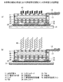
11,51 蒸発用筐体
12,13,52,53 管取り付け部
14,54 リッド
15,55 TIM
20,60 冷却配管系
21,61 蒸気管
22,62 液管
23,24,63,64 管取り付け部
25,65 ラジエータ
26,66 ファン
27,28,67,68 管取り付け部
29,69 ポンプ
30,70 被冷却電子機器
31,71 システムボード
32,72 回路基板
33,73 半導体集積回路装置
34,74 スティフナー
35,75 TIM
36,76 作動液
40,47 熱変形性放熱フィン
41 積層膜
42 形状記憶合金
43 高熱伝導性金属
44 天板
45 熱伝導性板状支持体
46 スペーサ
Claims (5)
- 半導体装置と熱的に接する熱伝導性蓋状部材と、
前記熱伝導性蓋状部材と熱的に接する蒸発用筐体と、
前記蒸発用筐体に接続された蒸気管及び液管と
前記蒸気管と前記液管に接続されたラジエータと、
前記ラジエータに空気を送風するファンと、
前記液管の中間部に接続されたポンプと、
前記蒸発用筐体の前記熱伝導性蓋状部材と接する面と反対側の面に設けられた熱により伸縮する熱変形性放熱フィンとを有し、
前記熱変形性放熱フィンは、所定温度以上に達したときに圧縮した状態から伸長した状態に変化する熱変形性放熱フィンであることを特徴とする二相流冷却装置。 - 前記熱変形性放熱フィンは、形状記憶合金と前記形状記憶合金より熱伝導性の高い高熱伝導性金属との積層膜からなることを特徴とする請求項1に記載の二相流冷却装置。
- 前記熱変形性放熱フィンが、コイル状の放熱フィン或いは板バネを折りたたんだ形状の放熱フィンであることを特徴とする請求項1または請求項2に記載の二相流冷却装置。
- 前記熱変形性放熱フィンの前記蒸発用筐体に固定されている端部と反対側の端部が熱伝導性板状支持部材に固定されていることを特徴とする請求項1乃至請求項3のいずれか1項に記載の二相流冷却装置。
- 蒸発用筐体と、
前記蒸発用筐体に蒸気管及び液管を取り付ける管取り付け部と、
前記蒸発用筐体の頂面に設けられた熱により伸縮する熱変形性放熱フィンと
を有し、
前記熱変形性放熱フィンは、所定温度以上に達したときに圧縮した状態から伸長した状態に変化する熱変形性放熱フィンであることを特徴とする二相流冷却装置用蒸発器。
Priority Applications (1)
| Application Number | Priority Date | Filing Date | Title |
|---|---|---|---|
| JP2013163133A JP6123555B2 (ja) | 2013-08-06 | 2013-08-06 | 二相流冷却装置及び二相流冷却装置用蒸発器 |
Applications Claiming Priority (1)
| Application Number | Priority Date | Filing Date | Title |
|---|---|---|---|
| JP2013163133A JP6123555B2 (ja) | 2013-08-06 | 2013-08-06 | 二相流冷却装置及び二相流冷却装置用蒸発器 |
Publications (2)
| Publication Number | Publication Date |
|---|---|
| JP2015032776A JP2015032776A (ja) | 2015-02-16 |
| JP6123555B2 true JP6123555B2 (ja) | 2017-05-10 |
Family
ID=52517833
Family Applications (1)
| Application Number | Title | Priority Date | Filing Date |
|---|---|---|---|
| JP2013163133A Active JP6123555B2 (ja) | 2013-08-06 | 2013-08-06 | 二相流冷却装置及び二相流冷却装置用蒸発器 |
Country Status (1)
| Country | Link |
|---|---|
| JP (1) | JP6123555B2 (ja) |
Families Citing this family (4)
| Publication number | Priority date | Publication date | Assignee | Title |
|---|---|---|---|---|
| US10353445B2 (en) * | 2016-04-11 | 2019-07-16 | Qualcomm Incorporated | Multi-phase heat dissipating device for an electronic device |
| CN107087384B (zh) * | 2017-06-28 | 2023-12-05 | 合肥联宝信息技术有限公司 | 散热器及散热装置 |
| US11181323B2 (en) | 2019-02-21 | 2021-11-23 | Qualcomm Incorporated | Heat-dissipating device with interfacial enhancements |
| CN112654206B (zh) * | 2020-11-05 | 2022-04-05 | 西安交通大学 | 矿井用5g基站轻量化散热系统 |
Family Cites Families (9)
| Publication number | Priority date | Publication date | Assignee | Title |
|---|---|---|---|---|
| JPS61186785A (ja) * | 1985-02-15 | 1986-08-20 | Matsushita Electric Works Ltd | 熱搬送器 |
| JPH0425290U (ja) * | 1990-06-25 | 1992-02-28 | ||
| JP3376346B2 (ja) * | 2000-09-25 | 2003-02-10 | 株式会社東芝 | 冷却装置、この冷却装置を有する回路モジュールおよび電子機器 |
| JP2006324394A (ja) * | 2005-05-18 | 2006-11-30 | Alps Electric Co Ltd | 放熱補助シート |
| TWI262285B (en) * | 2005-06-03 | 2006-09-21 | Foxconn Tech Co Ltd | Loop-type heat exchange apparatus |
| JP4593438B2 (ja) * | 2005-10-24 | 2010-12-08 | 富士通株式会社 | 電子機器および冷却モジュール |
| JP4757774B2 (ja) * | 2006-10-31 | 2011-08-24 | 富士通株式会社 | ヒートシンク |
| CN100460798C (zh) * | 2007-05-16 | 2009-02-11 | 中山大学 | 一种均温回路热管装置 |
| CN102042776A (zh) * | 2009-10-16 | 2011-05-04 | 富准精密工业(深圳)有限公司 | 回路热管 |
-
2013
- 2013-08-06 JP JP2013163133A patent/JP6123555B2/ja active Active
Also Published As
| Publication number | Publication date |
|---|---|
| JP2015032776A (ja) | 2015-02-16 |
Similar Documents
| Publication | Publication Date | Title |
|---|---|---|
| JP5210997B2 (ja) | 冷却システム、及び、それを用いる電子装置 | |
| JP6015675B2 (ja) | 冷却装置及びそれを用いた電子機器 | |
| US20110297355A1 (en) | Heat-conducting module and heat-dissipating device having the same | |
| JP2013257136A (ja) | 相変化放熱装置 | |
| JP6123555B2 (ja) | 二相流冷却装置及び二相流冷却装置用蒸発器 | |
| JP6269478B2 (ja) | 電子基板の冷却構造及びそれを用いた電子装置 | |
| JP2004111969A (ja) | 角度付きヒートパイプを備えたヒートシンク | |
| US20140054009A1 (en) | Cooling plate and water cooling device having the same | |
| US9763359B2 (en) | Heat pipe with near-azeotropic binary fluid | |
| JP2010267912A (ja) | 冷却装置 | |
| CN114003111A (zh) | 一种用于计算机芯片的散热设备 | |
| CN104303293B (zh) | 冷却装置的连接结构、冷却装置和连接冷却装置的方法 | |
| JP5723708B2 (ja) | 電子機器却装置 | |
| JP2000332175A (ja) | フィン付ヒートシンク | |
| JP2014013849A (ja) | 電子装置用放熱構造 | |
| CN210091871U (zh) | 散热骨架 | |
| JP5860728B2 (ja) | 電子機器の冷却システム | |
| JP2018101655A (ja) | 冷却装置、冷却方法、及び熱伝導体 | |
| JP5624771B2 (ja) | ヒートパイプおよびヒートパイプ付ヒートシンク | |
| JP2016133230A (ja) | 放熱装置 | |
| JP2013258404A (ja) | 相変化放熱装置 | |
| US8783333B1 (en) | Cooling system | |
| JP4757774B2 (ja) | ヒートシンク | |
| EP2801781B1 (en) | Cooling device | |
| JP6574404B2 (ja) | ヒートシンク構造 |
Legal Events
| Date | Code | Title | Description |
|---|---|---|---|
| A621 | Written request for application examination |
Free format text: JAPANESE INTERMEDIATE CODE: A621 Effective date: 20160510 |
|
| A977 | Report on retrieval |
Free format text: JAPANESE INTERMEDIATE CODE: A971007 Effective date: 20170227 |
|
| TRDD | Decision of grant or rejection written | ||
| A01 | Written decision to grant a patent or to grant a registration (utility model) |
Free format text: JAPANESE INTERMEDIATE CODE: A01 Effective date: 20170307 |
|
| A61 | First payment of annual fees (during grant procedure) |
Free format text: JAPANESE INTERMEDIATE CODE: A61 Effective date: 20170320 |
|
| R150 | Certificate of patent or registration of utility model |
Ref document number: 6123555 Country of ref document: JP Free format text: JAPANESE INTERMEDIATE CODE: R150 |