JP6122767B2 - Joint device - Google Patents
Joint device Download PDFInfo
- Publication number
- JP6122767B2 JP6122767B2 JP2013233661A JP2013233661A JP6122767B2 JP 6122767 B2 JP6122767 B2 JP 6122767B2 JP 2013233661 A JP2013233661 A JP 2013233661A JP 2013233661 A JP2013233661 A JP 2013233661A JP 6122767 B2 JP6122767 B2 JP 6122767B2
- Authority
- JP
- Japan
- Prior art keywords
- joint
- floor
- wall
- building
- joint device
- Prior art date
- Legal status (The legal status is an assumption and is not a legal conclusion. Google has not performed a legal analysis and makes no representation as to the accuracy of the status listed.)
- Active
Links
Images


Description
本発明は目地部を介して床躯体と壁躯体を備える左右の建物間の床躯体間と天井側の上部を除く部位の壁躯体間を覆う目地装置に関する。 The present invention relates to a joint device that covers a space between floor frames between left and right buildings including a floor frame and a wall frame and a wall frame of a portion excluding an upper part on a ceiling side via a joint part.
従来、この種の目地装置は、左右の建物の壁面間は床面から天井部分まで覆う壁面用目地装置が用いられていた。 Conventionally, this type of joint device is a wall joint device that covers from the floor to the ceiling between the walls of the left and right buildings.
しかしながら、左右の建物の壁面間に床面から天井部分より下の所定位置まで覆う壁面用目地装置を設置しようとすると、地震で左右の建物が前後方向に揺れ動くと、床部分に隙間が生じたり、この床部分の隙間を解消するために、壁用目地装置本体の一端部に前後方向にスライド移動可能に取付けられた可動壁目地プレートの上部をガイドするガイドレールが開口部側へ突出させて設置することができず、ふらつき、危険であるという欠点があった。 However, if a wall joint device is installed between the walls of the left and right buildings to cover a predetermined position below the ceiling from the floor, if the left and right buildings swing back and forth due to an earthquake, a gap will be created in the floor. In order to eliminate the gap in the floor portion, a guide rail that guides the upper portion of the movable wall joint plate attached to one end portion of the wall joint device main body so as to be slidable in the front-rear direction protrudes to the opening side. There was a drawback that it could not be installed, and it was unstable and dangerous.
本発明は以上のような従来の欠点に鑑み、壁面用目地装置を天井分部まで設置しなくても、壁面用目地装置本体の一端部に取付けられた、前後方向にスライド移動する可動壁目地プレートが開口部側へスライド移動しても、ふらつくことなく、安全で、強固に支持することができる目地装置を提供することを目的としている。 In view of the above-mentioned conventional drawbacks, the present invention is a movable wall joint attached to one end of a wall surface joint device main body and slidably moved in the front-rear direction without installing the wall surface joint device up to the ceiling part. An object of the present invention is to provide a joint device that can be safely and firmly supported without wobbling even if the plate slides toward the opening.
本発明の前記ならびにそのほかの目的と新規な特徴は次の説明を添付図面と照らし合わせて読むと、より完全に明らかになるであろう。
ただし、図面はもっぱら解説のためのものであって、本発明の技術的範囲を限定するものではない。
The above and other objects and novel features of the present invention will become more fully apparent when the following description is read in conjunction with the accompanying drawings.
However, the drawings are for explanation only and do not limit the technical scope of the present invention.
上記目的を達成するために、本発明は目地部を介して設けられた床躯体と壁躯体を備える左右の建物の床躯体間の目地部を覆う床用目地装置と、前記左右の建物の壁躯体間の目地部を天井側の上部を除く部位を覆う壁用目地装置とからなる目地装置において、前記床用目地装置を前記左右の建物の一方の建物の床躯体および、該床躯体より突出する一方の建物の目地部側壁躯体に取付けられたレールと、このレールに後端部がスライド移動可能に支持され、先端部が前記左右の建物の他方の建物の壁躯体間に平面視における左右方向に移動可能に挿入された床用目地プレートで構成するとともに、前記壁用目地装置を前記床用目地装置のレールと平行になるように、天井側の上部を除く部位の前記一方の建物の目地部側壁躯体に取付けられた支持レールと、 上部が該支持レールに支持され、下部が前記レールに支持された可動壁目地プレートと、この可動壁目地プレートの前記床用目地プレート側に一端部が枢支され、他端部が前記他方の建物の目地部側の壁躯体に枢支された伸縮可能な壁用目地装置本体と、一端が前記可動壁目地プレートに枢支され、他端部が該可動壁目地プレートと対向する前記他方の建物の目地部側壁躯体に枢支された中央枢支部が上方に位置する連結蝶番とで目地装置を構成している。 In order to achieve the above object, the present invention provides a floor joint device for covering a joint portion between floor frames of left and right buildings provided with a floor housing and a wall housing provided via joint portions, and the walls of the left and right buildings. In a joint device comprising a joint device for a wall covering a portion of the joint between the housings excluding the upper part on the ceiling side, the floor joint device projects from the floor housing of one of the left and right buildings and the floor housing. while a rail attached to the joint portion side wall skeleton building the rear end the rail is supported slidably, the left and right in a plan view tip between wall skeleton of the other buildings of the left and right building The floor joint plate is movably inserted in the direction, and the wall joint device is parallel to the rail of the floor joint device so that the one side of the building excluding the upper part on the ceiling side Mounted on joint side wall frame A holding rail, a movable wall joint plate having an upper portion supported by the support rail and a lower portion supported by the rail, and one end portion pivotally supported on the floor joint plate side of the movable wall joint plate, and the other end portion. Is a telescopic wall joint device body pivotally supported by a wall housing on the joint side of the other building, one end pivotally supported by the movable wall joint plate, and the other end opposed to the movable wall joint plate The joint device is composed of a central hinge portion pivotally supported by the joint portion side wall housing of the other building and the connecting hinge positioned above.
以上の説明から明らかなように、本発明にあっては次に列挙する効果が得られる。
(1)請求項1により、壁用目地装置の可動壁目地プレートを連結蝶番によって支持しているので、可動壁目地プレートが地震で開口部方向にスライド移動し、支持レールより突出しても、連結蝶番によって可動壁目地カバーがふらついたりすることなく、安全に支持することができ、安全に使用することができる。
(2)前記(1)により、連結蝶番の中央枢支部が上方に位置されているので、常時、両端部の枢支部が外方へ押し付けるような自重が加わり、より確実に可動壁目地プレートを正常な位置に保持でき、美観を損ねたり、隙間が生じたりするのを確実に防止することができる。
(3)前記(1)により、壁用目地装置本体を天井側の上部を除く部位に設置されているので、小型で、安価に製造でき、低コストで設置することができる。
(4)前記(1)により、地震で左右の建物が異なる前後左右方向に揺れ動いても、連結蝶番や可動壁目地プレートの移動で、その揺れ動きを吸収することができる。
(5)請求項2も前記(1)〜(4)と同様な効果が得られる。
As is clear from the above description, the present invention has the following effects.
(1) According to
(2) According to the above (1), the central pivot part of the connecting hinge is positioned upward, so that the weights of the pivot parts at both ends are always pushed outward, and the movable wall joint plate is more reliably attached. It can be held at a normal position, and it is possible to reliably prevent the appearance from being lost or a gap from occurring.
(3) According to the above (1), the wall joint device main body is installed in a portion excluding the upper part on the ceiling side, so that it is small and can be manufactured at low cost, and can be installed at low cost.
(4) According to the above (1), even if the buildings on the left and right are swayed in different directions in the front-rear and left-right directions due to the earthquake, the swaying motion can be absorbed by the movement of the connecting hinge and the movable wall joint plate.
(5) In the second aspect, the same effects as in the above (1) to (4) can be obtained.
以下、図面に示す本発明を実施するための形態により、本発明を詳細に説明する。 Hereinafter, the present invention will be described in detail with reference to the embodiments shown in the drawings.
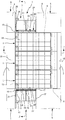
図1ないし図10に示す本発明を実施するための第1の形態において、1は目地部2を介して設けられた床躯体3、3と壁躯体4、4を備える左右の建物5、5の床躯体3、3間の目地部2を覆う床用目地装置6と、前記左右の建物5、5の壁躯体4、4間の目地部2を天井側の上部を除く部位を覆う壁用目地装置7、7とからなる本発明の目地装置で、この目地装置1の床用目地装置6は前記一方の建物の床躯体3の目地部側床躯体に形成された、反目地部側に傾斜面8が形成された目地プレートスライド支持凹部9と、この目地プレートスライド支持凹部9と対向する他方の建物5の床躯体3に水平方向に固定された開口部10よりも外方へ突出するレール11と、このレール11に沿って前後方向にスライド移動できるように下部に複数個のローラ12を取付けたスベリ体13に後端部が取付けられ、先端部が前記目地プレートスライド支持凹部9を覆うように支持された目地プレート14とで構成されている。
In the first embodiment for carrying out the present invention shown in FIG. 1 to FIG. 10,
前記目地装置1の壁用目地装置7、7は前記目地プレート14の後部両端部のスベリ体13に下端部が固定された支柱15、15と、この支柱15、15に一端部がヒンジ部材16、16で枢支され、他端部が一方の建物5の目地部側の壁躯体4、4にヒンジ部材17、17で枢支された伸縮可能な壁用目地装置本体18、18と、前記スベリ体13に下端部が取付けられるとともに、前記支柱15、15に一端部が取付けられた板状あるいは格子状の可動壁目地プレート19、19と、この可動壁目地プレート19、19の上端部がスライド移動できるように他方の建物5の目地部側壁躯体4に取付けられた支持レール20、20と、前記可動壁目地プレート19、19の上部を除く部位に一端部がヒンジ部材21で枢支され、他端部が該部とほぼ同じ位置の一方の建物5の目地部側壁躯体4にヒンジ部材22で枢支され、ほぼ45度の角度で上方へ突出する中央枢支部23を備える連結蝶番24、24とで構成されている。
The wall
前記壁用目地装置本体18、18は一端部が前記一方の建物5の目地部側壁躯体4にヒンジ部材17、17で取付けられ、他端部が前記支柱15、15にヒンジ部材16、16で取付けられた少なくとも2個以上の中央に中央枢支部25を有するパンタグラフ形状の伸縮リンク機構26、26、26、26と、この少なくとも2個以上のパンタグラフ形状の伸縮リンク機構26、26、26、26の両端部の取付部に取付けられた先端部に、傾斜面27、27が形成された両端部の目地部を覆う端部目地プレート28、28と、この端部目地プレート28、28の傾斜面27、27と面接触する傾斜面29、29を有し、かつ該端部目地プレート28、28の押し圧によって、前方へ突出するように付勢スプリング30で前記中央枢支部25に枢支された中央目地プレート31とで構成されたものが使用されている。
One end of the wall joint device
なお、壁用目地装置本体18、18は伸縮可能なものであれば、現在使用されているどんな構造のものであってもよく、また、特許第3662173号、特許第3820217号、特許第4079436号、特許第4836860号公報に開示された壁用目地装置であってもよい。
The wall joint device
上記構成の目地装置1は、通常状態では図1ないし図3に示すように左右の建物5、5の床躯体3、3間の目地部2は床用目地装置6で覆われているとともに、左右の建物5、5の壁躯体4、4間の天井側の上部を除く部位の目地部2は壁用目地装置7、7で覆われているため、安全に左右の建物5、5間を走行することができる。
In the normal state, the
地震で左右の建物5、5が異なる左右方向に揺れ動き、目地部2が狭くなった場合には、図5および図6に示すように床用目地装置6の目地プレート14の先端部が目地プレートスライド支持凹部9の傾斜面8に沿って、一方の建物5の床躯体3上へ突出するとともに、壁用目地装置7、7の壁用目地装置本体18、18は収縮して、目地部2に隙間が生じることなくその揺れ動きを吸収する。
When the left and
また、目地部2が広くなった場合には、図7および図8に示すように床用目地装置6の目地プレート14の先端部が目地プレートスライド支持凹部9上をスライド移動するとともに、壁用目地装置7、7の壁用目地装置本体18、18は伸縮して、目地部2に隙間が生じることなく、その揺れ動きを吸収する。
When the
地震で左右の建物5、5が異なる前後方向に揺れ動いた場合、図9および図10に示すように一方の建物5の壁躯体4、4によって床用目地装置6の目地プレート14の後端部レール11に沿って前後方向にスライド移動するとともに、この目地プレート14の前後方向のスライド移動によって、壁用目地装置7、7の支柱15、15も一体になって前後方向へスライド移動するため、可動壁目地プレート19、19も前後方向にスライド移動し、他方の建物5の開口部10内へ侵入して目地部2に開口するのを阻止する。
When the left and
なお、可動壁目地プレート19、19は連結蝶番24、24によって他方の建物5の目地部側壁躯体4方向に押し圧されたような状態となっており、可動壁目地プレート19、19の上部が支持レール20、20より突出するようにスライド移動しても、安定した状態で保持されていて、開口部10内へ突出した可動壁目地プレート19、19に衝突しても、可動壁目地プレート19、19が撓んで隙間が生じたりすることを確実に防止できる。
The movable wall
[発明を実施するための異なる形態]
次に、図11ないし図16に示す本発明を実施するための異なる形態につき説明する。なお、これらの本発明を実施するための異なる形態の説明に当って、前記本発明を実施するための第1の形態と同一構成部分には同一符号を付して重複する説明を省略する。
[Different forms for carrying out the invention]
Next, different modes for carrying out the present invention shown in FIGS. 11 to 16 will be described. In the description of the different embodiments for carrying out the present invention, the same components as those in the first embodiment for carrying out the present invention are denoted by the same reference numerals, and redundant description is omitted.
図11ないし図13に示す本発明を実施するための第2の形態において、前記本発明を実施するための第1の形態と主に異なる点は、目地プレート14の後部底面にレール11に沿って移動する複数個のローラ32を設けるとともに、目地プレート14の後端両側部に支柱取付部33、33を形成し、該支柱取付部33、33に支柱15、15を取付けた点で、このように構成した目地装置1Aにしても、前記本発明を実施するための第1の形態と同様な作用効果が得られる。
The second embodiment for carrying out the present invention shown in FIGS. 11 to 13 is mainly different from the first embodiment for carrying out the present invention in that the rear bottom surface of the
図14ないし図16に示す本発明を実施するための第3の形態において、前記本発明を実施するための第1の形態と主に異なる点は、四角枠状のフレーム34を用いた可動壁目地プレート19A、19Aを用いるとともに、該可動壁目地プレート19A、19Aのフレーム34、34をスベリ体13に固定した点で、このように構成した目地装置1Bにしても、前記本発明を実施するための第1の形態と同様な作用効果が得られる。
The third embodiment for carrying out the present invention shown in FIGS. 14 to 16 is mainly different from the first embodiment for carrying out the present invention in that a movable wall using a
本発明は目地部を介して床躯体と壁躯体を備える左右の建物間の床躯体間と天井側の上部を除く部位の壁躯体間を覆う目地装置を製造する産業で利用される。 INDUSTRIAL APPLICATION This invention is utilized by the industry which manufactures the joint apparatus which covers between the floor frame of the site | part between the right and left buildings provided with a floor frame and a wall frame, and the wall frame of the site | part except the upper part of a ceiling side via a joint part.
1、1A、1B:目地装置、 2:目地部、
3:床躯体、 4:壁躯体、
5:建物、 6:床用目地装置、
7:壁用目地装置 8:傾斜面、
9:目地プレートスライド支持凹部、
10:開口部、 11:レール、
12:ローラ、 13:スベリ体、
14:目地プレート、 15:支柱、
16:ヒンジ部材、 17:ヒンジ部材、
18:壁用目地装置本体、
19、19A:可動壁目地プレート、
20:支持レール、 21:ヒンジ部材、
22:ヒンジ部材、 23:中央枢支部、
24:連結蝶番、 25:中央枢支部、
26:伸縮リンク機構、 27:傾斜面、
28:端部目地プレート、 29:傾斜面、
30:付勢スプリング、 31:中央目地プレート、
32:ローラ、 33:支柱取付部、
34:フレーム。
1, 1A, 1B: joint device, 2: joint portion,
3: floor frame, 4: wall frame,
5: Building, 6: Joint device for floor,
7: Wall joint device 8: Inclined surface,
9: Joint plate slide support recess,
10: opening, 11: rail,
12: Roller, 13: Smooth body,
14: joint plate, 15: support,
16: Hinge member, 17: Hinge member,
18: Wall joint device body,
19, 19A: movable wall joint plate,
20: support rail, 21: hinge member,
22: Hinge member, 23: Central pivot,
24: Connection hinge, 25: Central pivot,
26: telescopic link mechanism, 27: inclined surface,
28: End joint plate, 29: Inclined surface,
30: Energizing spring, 31: Central joint plate,
32: Roller, 33: Prop mounting part,
34: Frame.
Claims (2)
Priority Applications (1)
| Application Number | Priority Date | Filing Date | Title |
|---|---|---|---|
| JP2013233661A JP6122767B2 (en) | 2013-11-12 | 2013-11-12 | Joint device |
Applications Claiming Priority (1)
| Application Number | Priority Date | Filing Date | Title |
|---|---|---|---|
| JP2013233661A JP6122767B2 (en) | 2013-11-12 | 2013-11-12 | Joint device |
Publications (2)
| Publication Number | Publication Date |
|---|---|
| JP2015094116A JP2015094116A (en) | 2015-05-18 |
| JP6122767B2 true JP6122767B2 (en) | 2017-04-26 |
Family
ID=53196722
Family Applications (1)
| Application Number | Title | Priority Date | Filing Date |
|---|---|---|---|
| JP2013233661A Active JP6122767B2 (en) | 2013-11-12 | 2013-11-12 | Joint device |
Country Status (1)
| Country | Link |
|---|---|
| JP (1) | JP6122767B2 (en) |
Family Cites Families (3)
| Publication number | Priority date | Publication date | Assignee | Title |
|---|---|---|---|---|
| JP3028505B2 (en) * | 1995-05-09 | 2000-04-04 | ドーエイ外装有限会社 | Joint cover device |
| JP4948236B2 (en) * | 2007-04-02 | 2012-06-06 | ドーエイ外装有限会社 | Floor joint device |
| JP4960334B2 (en) * | 2008-11-27 | 2012-06-27 | ドーエイ外装有限会社 | Passage wall joint device |
-
2013
- 2013-11-12 JP JP2013233661A patent/JP6122767B2/en active Active
Also Published As
| Publication number | Publication date |
|---|---|
| JP2015094116A (en) | 2015-05-18 |
Similar Documents
| Publication | Publication Date | Title |
|---|---|---|
| JP5862961B2 (en) | Floor joint device | |
| JP5862971B2 (en) | Floor joint device | |
| JP6033352B2 (en) | Joint device | |
| JP5931476B2 (en) | Boundary joint device | |
| JP6122767B2 (en) | Joint device | |
| JP2013151842A (en) | Ceiling joint device | |
| JP6534476B1 (en) | Cover plate support device and floor joint device | |
| JP5959013B2 (en) | Floor joint device | |
| JP5943862B2 (en) | Floor joint device | |
| JP5738807B2 (en) | Ceiling joint cover device | |
| JP2010242311A (en) | Joint device | |
| JP6309068B1 (en) | Floor joint device | |
| JP4110134B2 (en) | Floor joint device | |
| JP6293202B2 (en) | Joint device | |
| JP5102264B2 (en) | Floor joint device | |
| JP2010053506A (en) | Jointing device for ceiling | |
| JP6144645B2 (en) | Ceiling joint device | |
| JP5943877B2 (en) | Joint device | |
| JP2012219597A (en) | Joint device | |
| JP5364752B2 (en) | Joint device | |
| JP2017179978A (en) | Joint device for floor | |
| JP4801642B2 (en) | Crossing joint device | |
| JP4334513B2 (en) | Floor joint device | |
| JP4890426B2 (en) | Passage | |
| JP5670966B2 (en) | Joint device |
Legal Events
| Date | Code | Title | Description |
|---|---|---|---|
| A621 | Written request for application examination |
Free format text: JAPANESE INTERMEDIATE CODE: A621 Effective date: 20150604 |
|
| A977 | Report on retrieval |
Free format text: JAPANESE INTERMEDIATE CODE: A971007 Effective date: 20160307 |
|
| A131 | Notification of reasons for refusal |
Free format text: JAPANESE INTERMEDIATE CODE: A131 Effective date: 20160405 |
|
| A521 | Request for written amendment filed |
Free format text: JAPANESE INTERMEDIATE CODE: A523 Effective date: 20160513 |
|
| A131 | Notification of reasons for refusal |
Free format text: JAPANESE INTERMEDIATE CODE: A131 Effective date: 20161101 |
|
| A521 | Request for written amendment filed |
Free format text: JAPANESE INTERMEDIATE CODE: A523 Effective date: 20161115 |
|
| TRDD | Decision of grant or rejection written | ||
| A01 | Written decision to grant a patent or to grant a registration (utility model) |
Free format text: JAPANESE INTERMEDIATE CODE: A01 Effective date: 20170321 |
|
| A61 | First payment of annual fees (during grant procedure) |
Free format text: JAPANESE INTERMEDIATE CODE: A61 Effective date: 20170403 |
|
| R150 | Certificate of patent or registration of utility model |
Ref document number: 6122767 Country of ref document: JP Free format text: JAPANESE INTERMEDIATE CODE: R150 |
|
| R250 | Receipt of annual fees |
Free format text: JAPANESE INTERMEDIATE CODE: R250 |
|
| R250 | Receipt of annual fees |
Free format text: JAPANESE INTERMEDIATE CODE: R250 |