JP6119227B2 - Bearing roller state detecting device, roller bearing device with sensor, and wind power generator - Google Patents
Bearing roller state detecting device, roller bearing device with sensor, and wind power generator Download PDFInfo
- Publication number
- JP6119227B2 JP6119227B2 JP2012271473A JP2012271473A JP6119227B2 JP 6119227 B2 JP6119227 B2 JP 6119227B2 JP 2012271473 A JP2012271473 A JP 2012271473A JP 2012271473 A JP2012271473 A JP 2012271473A JP 6119227 B2 JP6119227 B2 JP 6119227B2
- Authority
- JP
- Japan
- Prior art keywords
- bearing
- sensor
- roller
- substrate
- processing unit
- Prior art date
- Legal status (The legal status is an assumption and is not a legal conclusion. Google has not performed a legal analysis and makes no representation as to the accuracy of the status listed.)
- Expired - Fee Related
Links
Images


Classifications
-
- F—MECHANICAL ENGINEERING; LIGHTING; HEATING; WEAPONS; BLASTING
- F03—MACHINES OR ENGINES FOR LIQUIDS; WIND, SPRING, OR WEIGHT MOTORS; PRODUCING MECHANICAL POWER OR A REACTIVE PROPULSIVE THRUST, NOT OTHERWISE PROVIDED FOR
- F03D—WIND MOTORS
- F03D17/00—Monitoring or testing of wind motors, e.g. diagnostics
-
- F—MECHANICAL ENGINEERING; LIGHTING; HEATING; WEAPONS; BLASTING
- F16—ENGINEERING ELEMENTS AND UNITS; GENERAL MEASURES FOR PRODUCING AND MAINTAINING EFFECTIVE FUNCTIONING OF MACHINES OR INSTALLATIONS; THERMAL INSULATION IN GENERAL
- F16C—SHAFTS; FLEXIBLE SHAFTS; ELEMENTS OR CRANKSHAFT MECHANISMS; ROTARY BODIES OTHER THAN GEARING ELEMENTS; BEARINGS
- F16C41/00—Other accessories, e.g. devices integrated in the bearing not relating to the bearing function as such
- F16C41/008—Identification means, e.g. markings, RFID-tags; Data transfer means
-
- F—MECHANICAL ENGINEERING; LIGHTING; HEATING; WEAPONS; BLASTING
- F16—ENGINEERING ELEMENTS AND UNITS; GENERAL MEASURES FOR PRODUCING AND MAINTAINING EFFECTIVE FUNCTIONING OF MACHINES OR INSTALLATIONS; THERMAL INSULATION IN GENERAL
- F16C—SHAFTS; FLEXIBLE SHAFTS; ELEMENTS OR CRANKSHAFT MECHANISMS; ROTARY BODIES OTHER THAN GEARING ELEMENTS; BEARINGS
- F16C19/00—Bearings with rolling contact, for exclusively rotary movement
- F16C19/52—Bearings with rolling contact, for exclusively rotary movement with devices affected by abnormal or undesired conditions
- F16C19/522—Bearings with rolling contact, for exclusively rotary movement with devices affected by abnormal or undesired conditions related to load on the bearing, e.g. bearings with load sensors or means to protect the bearing against overload
-
- F—MECHANICAL ENGINEERING; LIGHTING; HEATING; WEAPONS; BLASTING
- F16—ENGINEERING ELEMENTS AND UNITS; GENERAL MEASURES FOR PRODUCING AND MAINTAINING EFFECTIVE FUNCTIONING OF MACHINES OR INSTALLATIONS; THERMAL INSULATION IN GENERAL
- F16C—SHAFTS; FLEXIBLE SHAFTS; ELEMENTS OR CRANKSHAFT MECHANISMS; ROTARY BODIES OTHER THAN GEARING ELEMENTS; BEARINGS
- F16C19/00—Bearings with rolling contact, for exclusively rotary movement
- F16C19/52—Bearings with rolling contact, for exclusively rotary movement with devices affected by abnormal or undesired conditions
- F16C19/527—Bearings with rolling contact, for exclusively rotary movement with devices affected by abnormal or undesired conditions related to vibration and noise
-
- F—MECHANICAL ENGINEERING; LIGHTING; HEATING; WEAPONS; BLASTING
- F16—ENGINEERING ELEMENTS AND UNITS; GENERAL MEASURES FOR PRODUCING AND MAINTAINING EFFECTIVE FUNCTIONING OF MACHINES OR INSTALLATIONS; THERMAL INSULATION IN GENERAL
- F16C—SHAFTS; FLEXIBLE SHAFTS; ELEMENTS OR CRANKSHAFT MECHANISMS; ROTARY BODIES OTHER THAN GEARING ELEMENTS; BEARINGS
- F16C33/00—Parts of bearings; Special methods for making bearings or parts thereof
- F16C33/30—Parts of ball or roller bearings
- F16C33/34—Rollers; Needles
- F16C33/36—Rollers; Needles with bearing-surfaces other than cylindrical, e.g. tapered; with grooves in the bearing surfaces
- F16C33/366—Tapered rollers, i.e. rollers generally shaped as truncated cones
-
- F—MECHANICAL ENGINEERING; LIGHTING; HEATING; WEAPONS; BLASTING
- F16—ENGINEERING ELEMENTS AND UNITS; GENERAL MEASURES FOR PRODUCING AND MAINTAINING EFFECTIVE FUNCTIONING OF MACHINES OR INSTALLATIONS; THERMAL INSULATION IN GENERAL
- F16C—SHAFTS; FLEXIBLE SHAFTS; ELEMENTS OR CRANKSHAFT MECHANISMS; ROTARY BODIES OTHER THAN GEARING ELEMENTS; BEARINGS
- F16C33/00—Parts of bearings; Special methods for making bearings or parts thereof
- F16C33/30—Parts of ball or roller bearings
- F16C33/46—Cages for rollers or needles
- F16C33/52—Cages for rollers or needles with no part entering between, or touching, the bearing surfaces of the rollers
- F16C33/523—Cages for rollers or needles with no part entering between, or touching, the bearing surfaces of the rollers with pins extending into holes or bores on the axis of the rollers
- F16C33/526—Cages for rollers or needles with no part entering between, or touching, the bearing surfaces of the rollers with pins extending into holes or bores on the axis of the rollers extending through the rollers and joining two lateral cage parts
-
- F—MECHANICAL ENGINEERING; LIGHTING; HEATING; WEAPONS; BLASTING
- F16—ENGINEERING ELEMENTS AND UNITS; GENERAL MEASURES FOR PRODUCING AND MAINTAINING EFFECTIVE FUNCTIONING OF MACHINES OR INSTALLATIONS; THERMAL INSULATION IN GENERAL
- F16C—SHAFTS; FLEXIBLE SHAFTS; ELEMENTS OR CRANKSHAFT MECHANISMS; ROTARY BODIES OTHER THAN GEARING ELEMENTS; BEARINGS
- F16C19/00—Bearings with rolling contact, for exclusively rotary movement
- F16C19/22—Bearings with rolling contact, for exclusively rotary movement with bearing rollers essentially of the same size in one or more circular rows, e.g. needle bearings
- F16C19/34—Bearings with rolling contact, for exclusively rotary movement with bearing rollers essentially of the same size in one or more circular rows, e.g. needle bearings for both radial and axial load
- F16C19/36—Bearings with rolling contact, for exclusively rotary movement with bearing rollers essentially of the same size in one or more circular rows, e.g. needle bearings for both radial and axial load with a single row of rollers
- F16C19/364—Bearings with rolling contact, for exclusively rotary movement with bearing rollers essentially of the same size in one or more circular rows, e.g. needle bearings for both radial and axial load with a single row of rollers with tapered rollers, i.e. rollers having essentially the shape of a truncated cone
-
- F—MECHANICAL ENGINEERING; LIGHTING; HEATING; WEAPONS; BLASTING
- F16—ENGINEERING ELEMENTS AND UNITS; GENERAL MEASURES FOR PRODUCING AND MAINTAINING EFFECTIVE FUNCTIONING OF MACHINES OR INSTALLATIONS; THERMAL INSULATION IN GENERAL
- F16C—SHAFTS; FLEXIBLE SHAFTS; ELEMENTS OR CRANKSHAFT MECHANISMS; ROTARY BODIES OTHER THAN GEARING ELEMENTS; BEARINGS
- F16C19/00—Bearings with rolling contact, for exclusively rotary movement
- F16C19/52—Bearings with rolling contact, for exclusively rotary movement with devices affected by abnormal or undesired conditions
- F16C19/525—Bearings with rolling contact, for exclusively rotary movement with devices affected by abnormal or undesired conditions related to temperature and heat, e.g. insulation
-
- F—MECHANICAL ENGINEERING; LIGHTING; HEATING; WEAPONS; BLASTING
- F16—ENGINEERING ELEMENTS AND UNITS; GENERAL MEASURES FOR PRODUCING AND MAINTAINING EFFECTIVE FUNCTIONING OF MACHINES OR INSTALLATIONS; THERMAL INSULATION IN GENERAL
- F16C—SHAFTS; FLEXIBLE SHAFTS; ELEMENTS OR CRANKSHAFT MECHANISMS; ROTARY BODIES OTHER THAN GEARING ELEMENTS; BEARINGS
- F16C2233/00—Monitoring condition, e.g. temperature, load, vibration
-
- F—MECHANICAL ENGINEERING; LIGHTING; HEATING; WEAPONS; BLASTING
- F16—ENGINEERING ELEMENTS AND UNITS; GENERAL MEASURES FOR PRODUCING AND MAINTAINING EFFECTIVE FUNCTIONING OF MACHINES OR INSTALLATIONS; THERMAL INSULATION IN GENERAL
- F16C—SHAFTS; FLEXIBLE SHAFTS; ELEMENTS OR CRANKSHAFT MECHANISMS; ROTARY BODIES OTHER THAN GEARING ELEMENTS; BEARINGS
- F16C2300/00—Application independent of particular apparatuses
- F16C2300/10—Application independent of particular apparatuses related to size
- F16C2300/14—Large applications, e.g. bearings having an inner diameter exceeding 500 mm
-
- F—MECHANICAL ENGINEERING; LIGHTING; HEATING; WEAPONS; BLASTING
- F16—ENGINEERING ELEMENTS AND UNITS; GENERAL MEASURES FOR PRODUCING AND MAINTAINING EFFECTIVE FUNCTIONING OF MACHINES OR INSTALLATIONS; THERMAL INSULATION IN GENERAL
- F16C—SHAFTS; FLEXIBLE SHAFTS; ELEMENTS OR CRANKSHAFT MECHANISMS; ROTARY BODIES OTHER THAN GEARING ELEMENTS; BEARINGS
- F16C2360/00—Engines or pumps
- F16C2360/31—Wind motors
-
- Y—GENERAL TAGGING OF NEW TECHNOLOGICAL DEVELOPMENTS; GENERAL TAGGING OF CROSS-SECTIONAL TECHNOLOGIES SPANNING OVER SEVERAL SECTIONS OF THE IPC; TECHNICAL SUBJECTS COVERED BY FORMER USPC CROSS-REFERENCE ART COLLECTIONS [XRACs] AND DIGESTS
- Y02—TECHNOLOGIES OR APPLICATIONS FOR MITIGATION OR ADAPTATION AGAINST CLIMATE CHANGE
- Y02E—REDUCTION OF GREENHOUSE GAS [GHG] EMISSIONS, RELATED TO ENERGY GENERATION, TRANSMISSION OR DISTRIBUTION
- Y02E10/00—Energy generation through renewable energy sources
- Y02E10/70—Wind energy
- Y02E10/72—Wind turbines with rotation axis in wind direction
Description
本発明は、軸受用ころの状態を検出するための状態検出装置、ころセンサ付き軸受装置、及び風力発電機に関する。 The present invention relates to a state detection device for detecting the state of a bearing roller, a bearing device with a roller sensor, and a wind power generator.
転がり軸受の実際の使用環境下において、当該転がり軸受に作用している軸受荷重等、転がり軸受の物理的な状態を把握することは、当該転がり軸受の設計の最適化や、耐久性評価、寿命予測等を行う上で重要である。
このため従来から、ころに作用する荷重を検出するセンサと、センサケーブルを介して前記センサに接続され前記センサの出力を取得して記録する記録装置とを備えた軸受用荷重検出装置を軸受のころに設け、転がり軸受に作用する荷重を測定する試みがなされている。
Under the actual usage environment of a rolling bearing, grasping the physical state of the rolling bearing, such as the bearing load acting on the rolling bearing, can optimize the design of the rolling bearing, evaluate its durability, This is important for making predictions.
Therefore, conventionally, a bearing load detection device comprising a sensor for detecting a load acting on a roller and a recording device connected to the sensor via a sensor cable to acquire and record the output of the sensor is provided. Attempts have been made to measure the load provided on the rollers and acting on the rolling bearing.
前記軸受用荷重検出装置は、前記ころに作用する荷重を軸受荷重として測定する装置であり、前記センサを前記ころの軸中心に形成された貫通孔の内周面に固定し、転がり軸受を運転させたときに、前記ころに作用する荷重を前記センサにより測定することで転がり軸受に作用する荷重を測定する(例えば、特許文献1参照)。 The bearing load detection device is a device for measuring a load acting on the roller as a bearing load, and the sensor is fixed to an inner peripheral surface of a through hole formed at a shaft center of the roller to operate a rolling bearing. When this is done, the load acting on the roller bearing is measured by measuring the load acting on the roller with the sensor (see, for example, Patent Document 1).
上記従来の軸受用荷重検出装置は、前記センサを前記ころの貫通孔内部に固定するとともに、前記記録装置をころの端面に軸方向に突出させた状態で固定している。このため、本来は突出物等のないころの端面側に、前記記録装置を設置するための余分なスペースを確保する必要があり、余分なスペースを確保できない場合には、その軸受には上記軸受用荷重検出装置を設けることができないこととなり、適用可能な軸受が制限されてしまう。 In the conventional bearing load detection device, the sensor is fixed inside the through hole of the roller, and the recording device is fixed to the end surface of the roller in a state of protruding in the axial direction. For this reason, it is necessary to secure an extra space for installing the recording device on the end face side of the roller that does not originally have a protrusion or the like. The load detecting device for use cannot be provided, and applicable bearings are limited.
さらに、記録装置が端面から突出しているので、前記ころを転がり軸受に組み込む際に、前記記録装置を周辺部材に接触させてしまうことがある。このように、前記記録装置を周辺機器に接触させてしまうと、記録装置の破損や、記録装置とセンサとを繋ぐケーブルの断線が生じ、センサ等に動作異常を生じさせてしまう懸念もあった。 Furthermore, since the recording device protrudes from the end face, the recording device may be brought into contact with a peripheral member when the roller is incorporated into a rolling bearing. As described above, if the recording apparatus is brought into contact with peripheral devices, the recording apparatus may be damaged, or the cable connecting the recording apparatus and the sensor may be disconnected, which may cause abnormal operation of the sensor or the like. .
本発明はこのような事情に鑑みてなされたものであり、軸受組み込みの際にセンサ異常を生じさせてしまうのを抑制し、かつ余分なスペースを確保せずとも軸受に組み込むことができる軸受用ころの状態検出装置、センサ付きころ軸受装置、及び風力発電機を提供することを目的とする。 The present invention has been made in view of such circumstances, and for bearings that can be prevented from causing sensor abnormality during the incorporation of the bearing and can be incorporated into the bearing without securing an extra space. An object of the present invention is to provide a roller state detection device, a roller bearing device with a sensor, and a wind power generator.
上記目的を達成するための本発明は、第1軌道輪と、前記第1軌道輪と同心に配置される第2軌道輪との間に転動自在に配置される軸受用ころの物理的な状態を検出する状態検出装置であって、前記軸受用ころの物理的な状態を検出するセンサと、前記センサが出力する検出信号を取得し、前記検出信号の処理を行って外部に送信する処理部と、を備え、前記センサ及び前記処理部は、前記軸受用ころの軸中心に設けられた中心孔の内部に収容され、前記処理部は、基板上に設けられており、前記基板は、前記中心孔の内側面に対して非接触状態で前記中心孔の内部に収容され、前記基板と、前記中心孔の内側面との間に介在し、前記基板を前記中心孔の内側面に対して非接触状態で保持する基板保持材をさらに備え、前記センサは、信号を出力するためのリード線を介して前記処理部に接続された状態で、前記中心孔の内周面に直接固定され、前記基板保持材は、前記基板の剛性よりも低い剛性の素材によって形成され、前記基板は、前記基板保持材のみで保持されていることを特徴としている。 In order to achieve the above object, the present invention provides a physical bearing roller that is disposed between a first race ring and a second race ring that is arranged concentrically with the first race ring. A state detection device that detects a state, a sensor that detects a physical state of the bearing roller, and a process that acquires a detection signal output from the sensor, processes the detection signal, and transmits the detection signal to the outside The sensor and the processing unit are housed in a central hole provided at the center of the shaft of the bearing roller, the processing unit is provided on a substrate, the substrate, It is accommodated in the center hole in a non-contact state with respect to the inner surface of the center hole, and is interposed between the substrate and the inner surface of the center hole, and the substrate is disposed on the inner surface of the center hole. non-contact state further includes a substrate holding member for holding at Te, the sensor, the signal The substrate holding material is directly fixed to the inner peripheral surface of the center hole in a state of being connected to the processing portion via a lead wire for applying force, and the substrate holding material is formed of a material having rigidity lower than that of the substrate. The substrate is held only by the substrate holding material .
上記構成の状態検出装置によれば、センサ及び処理部が、軸受用ころの軸中心に設けられた中心孔の内部に収容されるので、上記従来例の記憶装置のように、ころの端部から突出固定される、センサに関連する付帯物等がない。このため、余分なスペースを確保せずともセンサ及び処理部が設けられたころを軸受に組み込むことができる。
さらに、上記構成の状態検出装置では、センサ及び処理部が、軸受用ころの軸中心に設けられた中心孔の内部に収容されるので、センサ及び処理部が設けられたころを軸受に組み込む際に、センサや処理部が周辺機器に直接接触することがない。このため、周辺機器に対する接触によってセンサや処理部に故障や動作異常を生じさせてしまうことを抑制することができる。
さらに、基板保持材によって、基板を中心孔の内側面に対して非接触状態で保持することができるので、軸受が運転状態のときに、ころに作用する応力や振動が中心孔の内側面を介して基板に伝搬するのを抑制することができる。これにより、ころに作用する応力や振動によって基板に破損が生じ、センサ及び処理部の動作に異常が生じるのを抑制できる。
According to the state detection device having the above-described configuration, the sensor and the processing unit are accommodated in the center hole provided at the center of the shaft of the bearing roller. There is no incidental object related to the sensor that is fixedly protruding from the sensor. For this reason, the roller provided with the sensor and the processing unit can be incorporated into the bearing without securing an extra space.
Furthermore, in the state detection device having the above-described configuration, the sensor and the processing unit are accommodated in the center hole provided in the center of the shaft of the bearing roller. Therefore, when the roller provided with the sensor and the processing unit is incorporated into the bearing, In addition, the sensor and the processing unit do not directly contact peripheral devices. For this reason, it can suppress that a failure and operation abnormality are caused to a sensor or a processing part by contact with peripheral equipment.
Furthermore, since the substrate holding material can hold the substrate in a non-contact state with respect to the inner surface of the center hole, when the bearing is in an operating state, stress and vibration acting on the rollers cause the inner surface of the center hole to move. Propagation to the substrate can be suppressed. Thereby, it can suppress that a board | substrate is damaged with the stress and vibration which act on a roller, and abnormality arises in operation | movement of a sensor and a process part.
上記状態検出装置において、前記処理部は、前記センサの検出信号を処理して得た検出データを記憶する記憶部を備えていてもよく、この場合、軸受が運転状態のときに検出される検出信号を記憶部に逐次、記憶蓄積しておき、後に、軸受が停止したときに、有線通信等によって、記憶部に蓄積された検出信号を検出結果として外部機器に対して送信することができる。このため、例えば、検出結果を無線通信等によって逐次送信する場合と比較して、検出結果に含まれるノイズ等の影響を低減することができる。 In the state detection device, the processing unit may include a storage unit that stores detection data obtained by processing a detection signal of the sensor, and in this case, detection detected when the bearing is in an operating state. The signals are sequentially stored in the storage unit, and when the bearing stops later, the detection signal stored in the storage unit can be transmitted to the external device as a detection result by wired communication or the like. For this reason, compared with the case where a detection result is transmitted sequentially by radio | wireless communication etc., the influence of the noise etc. which are contained in a detection result can be reduced, for example.
また、上記状態検出装置において、前記基板保持材は、基板の剛性よりも低い剛性の素材によって形成されていることが好ましく、この場合、ころに作用する応力や振動が基板に伝搬するのをより確実に抑制することができる。 In the state detection device, the substrate holding material is preferably formed of a material having rigidity lower than that of the substrate. In this case, it is more effective for stress and vibration acting on the rollers to propagate to the substrate. It can be surely suppressed.
また、本発明は、第1軌道輪と、前記第1軌道輪と互いに同心に配置される第2軌道輪と、両軌道輪の間に転動自在に配置される複数の軸受用ころと、前記軸受用ころの物理的な状態を検出する状態検出装置と、を備えたセンサ付きころ軸受装置において、前記状態検出装置が、上述の状態検出装置であることを特徴としている。
上記構成のセンサ付きころ軸受装置によれば、上述したように、軸受組み込みの際にセンサに動作異常を生じさせてしまうのを抑制し、かつ余分なスペースを確保せずともセンサ等を軸受に組み込むことができる。
The present invention also includes a first bearing ring, a second bearing ring disposed concentrically with the first bearing ring, and a plurality of bearing rollers disposed between the bearing rings so as to be freely rotatable. A roller bearing device with a sensor comprising a state detection device for detecting a physical state of the bearing roller, wherein the state detection device is the state detection device described above.
According to the roller bearing device with a sensor having the above-described configuration, as described above, it is possible to prevent the sensor from malfunctioning when the bearing is assembled, and the sensor or the like to the bearing without securing an extra space. Can be incorporated.
本発明は、風力を受ける回転翼に一体回転可能に設けられた主軸と、前記主軸の回転力で発電する発電機と、前記主軸を回転自在に支持する軸受装置と、を備えた風力発電機において、前記軸受装置が、上述のセンサ付きころ軸受装置であることを特徴している。
上記構成の風力発電機によれば、軸受組み込みの際にセンサに動作異常を生じさせてしまうのを抑制し、かつ余分なスペースを確保せずともセンサ等を軸受に組み込むことができる。
The present invention provides a wind turbine generator comprising: a main shaft provided rotatably on a rotor blade that receives wind power; a generator that generates electric power by the rotational force of the main shaft; and a bearing device that rotatably supports the main shaft. In the invention, the bearing device is the above-described roller bearing device with a sensor.
According to the wind power generator having the above-described configuration, it is possible to suppress an abnormal operation of the sensor when the bearing is incorporated, and the sensor or the like can be incorporated into the bearing without securing an extra space.
本発明の軸受用ころの状態検出装置、センサ付きころ軸受装置、及び風力発電機によれば、軸受組み込みの際にセンサに動作異常を生じさせてしまうのを抑制し、かつ余分なスペースを確保せずとも軸受に組み込むことができる。 According to the bearing roller state detection device, the sensor-equipped roller bearing device, and the wind power generator of the present invention, it is possible to suppress abnormal operation of the sensor when the bearing is incorporated, and to secure an extra space. Without being able to be incorporated into the bearing.
次に、本発明の好ましい実施形態について添付図面を参照しながら説明する。図1は、本発明の第1の実施形態に係る状態検出装置を適用した円すいころ軸受の断面図である。本実施の形態の円すいころ軸受10は、ピンタイプ保持器11を備えたものであり、外輪(第1軌道輪)12、内輪(第2軌道輪)13、複数の円すいころ14、及びピンタイプ保持器11を備えている。
Next, preferred embodiments of the present invention will be described with reference to the accompanying drawings. FIG. 1 is a sectional view of a tapered roller bearing to which a state detection device according to a first embodiment of the present invention is applied. The tapered roller bearing 10 of the present embodiment includes a
外輪12は、その外周側がハウジング16に固定され、内周側には軸方向に対して傾斜する外輪軌道面17を有している。また、外輪12は、軸方向の一端部が他端部よりも径方向に厚く形成されることによって断面形状が台形状に形成されている。
また、内輪13は、内周側に回転軸18が嵌合され、外周側には軸方向に対して傾斜するとともに外輪軌道面17に対向する内輪軌道面19を有している。また、内輪軌道面19の軸方向両側には、円すいころ14の軸方向の移動を規制する鍔部20が形成されている。
The
The
複数の円すいころ14は、外輪軌道面17と内輪軌道面19との間に、保持器11によって保持された状態で周方向に間隔をあけて配置されている。また、各円すいころ14の軸中心には貫通孔22が形成されている。この貫通孔22は、円すいころ14の中心軸に沿って延び、円すいころ14を貫通している。
The plurality of
保持器11は、環状の第1リング23と、この第1リング23に対して軸方向に間隔をあけて設けられた環状の第2リング24と、第1,第2リング23,24を連結する丸棒状のピン25とを備えている。
第1リング23には、周方向に間隔をあけて複数のネジ孔26が貫通・形成されている。第2リング24は、第1リング23の内径よりも小さい内径、及び第1リング23の外径よりも小さい外径を有し、周方向に間隔をあけて複数の取付孔27が形成されている。
The
A plurality of screw holes 26 are formed through the
ピン25の一端部には、雄ネジ29が形成されている。雄ネジ部29は、第1リング23のネジ孔26に螺合されている。ピン25の他端部30は、第2リング24の取付孔27に圧入されている。ピン25は、両端が第1,第2リング23,24に螺合、圧入されることで、第1,第2リング23,24に固定されている。また、ピン25の長さ方向中途部は、円すいころ14の貫通孔22に挿通され、円すいころ14を回転自在に支持している。
A
なお、他端部30は、圧入後、第2リング24の取付孔27の周囲に溶接されていてもよい。
また、他端部30の外径寸法が、第2リング24の取付孔27に対して、例えば、0〜0.1mm程度のすき間が形成される程度の嵌め合いとなるようにピン25を形成し、他端部30を取付孔27に挿入した後、他端部30の端面側から溶接することで、ピン25の他端部30を第2リング24に固定してもよい。
さらに、ピン25の一端部についても、雄ネジ部29を螺合することによる第1リング23への固定に代えて、第1リング23に取付孔を設けるとともに、ピン25の一端部に前記取付孔に対して0〜0.1mm程度のすき間が形成される程度の嵌め合いとなる挿入部を設け、前記挿入部を前記取付孔に挿入した後、挿入部の端面側から溶接することによって一端部を第1リング23に固定してもよい。
The
Further, the
Further, with respect to one end portion of the
以上の構成を有する円すいころ軸受10においては、回転軸18の回転に伴って内輪13が回転し、この内輪13の回転に伴って、各円すいころ14が、自身の軸心回りに自転しながら円すいころ軸受10の軸心回りに公転運動する。
In the tapered
本実施形態において、上記複数の円すいころ14の内、少なくとも1つの円すいころ14には、ころの物理的状態を検出する状態検出装置を構成している、当該円すいころ14に作用する荷重を検出するための歪ゲージ、及び前記歪ゲージの出力信号の処理を行う処理部が設けられている。
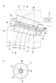
図2(a)は、歪ゲージ及び処理部が設けられている円すいころ14を含む円すいころ軸受10の断面図である。図2(a)中、円すいころ14(以下、「検出対象ころ」ともいう)に設けられている歪ゲージ40、及び処理部41は、円すいころ14の貫通孔22の内部に収容されている。
In the present embodiment, at least one
FIG. 2A is a cross-sectional view of the tapered
歪ゲージ40は、上述したように、円すいころ14に作用する荷重を検出するものであり、円すいころ14の状態として、当該円すいころ14に作用する荷重を検出するためのセンサを構成している。
歪ゲージ40は、貫通孔22の軸方向両端部に2箇所設けられており、貫通孔22の内周面22aに強固に接着固定されている。歪ゲージ40は、リード線等を介して処理部41に接続されており、このリード線を通じて処理部41に対して検出信号を出力する。
As described above, the
Two
処理部41は、歪ゲージ40が出力する検出信号を取得し、この検出信号の処理を行って外部に送信する機能を有している。
処理部41は、基板42上に実装された回路やICチップ等によって構成される機能部である。したがって、図2(a)に示すように、処理部41を構成する回路やICチップ等が実装された基板42が貫通孔22に収容されている。
The
The
図2(b)は、図2(a)中、B−B線矢視断面図である。図2(a)及び(b)に示すように、基板42は、貫通孔22の内周面22aに対して非接触状態で貫通孔22の内部に収容されている。
貫通孔22の内部には、基板保持材43が充填されている。基板保持材43は、シリコンゴム等のゴム状の弾性体によって形成されている。
基板保持材43は、経時変化によって硬化し弾性体となる液状ゴム等の液状素材を用いて形成されている。基板保持材43は、前記液状素材を貫通孔22に流し込んで充填した後、所定時間放置することによって前記液状素材を硬化させることで弾性体として形成されている。
FIG. 2B is a cross-sectional view taken along line B-B in FIG. As shown in FIGS. 2A and 2B, the
A
The
前記液状素材を貫通孔22に充填するには、まず、貫通孔22の内周面22aに歪ゲージ40を接着固定する。次いで、歪ゲージ40から延びるリード線を基板42(処理部41)に結線し、治具等によって、基板42、及び後述する通信コネクタ44を、貫通孔22の内部の所定位置に収容し保持する。このとき、基板42は、貫通孔22の内周面22aに対して非接触状態で保持する。
その後、前記液状素材を、貫通孔22に流し込んで充填する。このとき、前記液状素材は、基板42と、貫通孔22の内周面22aとの間に介在するように充填される。その状態で前記液状素材が硬化することで、弾性体としての基板保持材43が貫通孔22内部に形成される。
In order to fill the through
Thereafter, the liquid material is poured into the through
上記のように形成された基板保持材43は、基板42と、貫通孔22の内周面22aとの間に介在するように形成され、基板42を貫通孔22の内周面22aに対して非接触状態で貫通孔22の内部に保持している。
The
本実施形態では、基板保持材43によって、基板42を貫通孔22の内周面22aに対して非接触状態で保持することができるので、円すいころ軸受10が運転状態のときに、検出対象ころに作用する応力や振動が内周面22aを介して基板42に伝搬するのを抑制することができる。これにより、検出対象ころに作用する応力や振動によって基板42に破損が生じ、歪ゲージ40及び処理部41の動作に異常が生じるのを抑制できる。
In the present embodiment, since the
なお、弾性体である基板保持材43は、基板42の剛性よりも低い剛性とされており、円すいころ14に作用する応力や振動が基板42に伝搬するのをより確実に抑制する。
具体的に基板保持材43に用いる素材としては、例えば、低温(100℃前後)で硬化するシリコンゴム KE−1886(信越シリコーン(株)製)を用いることができる。
The
Specifically, as a material used for the
図2(a)を参照して、貫通孔22の内部には、通信コネクタ44も収容されている。この通信コネクタ44は、処理部41に信号線等を介して接続されている。通信コネクタ44は、貫通孔22の円すいころ14小径端側の開口部に、接続口44aがころ端面から露出するように配置されている。このため、通信コネクタ44は、保持器11の第2リング24に形成された取付孔27から接続口44aを臨むことができる位置に配置されている。このように配置することで、取付孔27を通じて外部機器から延びる通信ケーブルを通信コネクタ44に接続することができる。
With reference to FIG. 2A, a
通信コネクタ44には、外部に設置されたパーソナルコンピュータ(パソコン)Pから延びる通信ケーブルCが接続される。
処理部41は、歪ゲージ40が出力した検出信号に基づく検出データを通信コネクタ44、及び通信ケーブルCを介してパソコンPに送信する。
A communication cable C extending from a personal computer (personal computer) P installed outside is connected to the
The
図3は、検出対象ころ14Aを含んだ円すいころ軸受10を小径端面側からみたときの外観図である。通信コネクタ44は、上述のように、第2リング24に形成された取付孔27から接続口44aを臨むことができる位置に配置されている。
FIG. 3 is an external view of the tapered
検出対象ころ14Aの貫通孔22には、基板42、及び基板保持材43が設けられているので、保持器11のピン25は挿通できない。このため、本実施形態では、図3に示すようなセパレータ45によって、検出対象ころ14Aの周方向の位置を保持している。このセパレータ45は、断面形状が略T字型に形成され、検出対象ころ14Aと、その両側の円すいころ14との間に配置されており、各円すいころ14,14Aの径方向中間部と径方向外側部とに当接して各円すいころ14,14Aの間隔を保っている。また、セパレータ45は、円すいころ14の軸方向長さと略同一の長さを有しており、第1リング23と第2リング24の間に隙間をもって挟まれている。
Since the
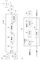
図4(a)は、歪ゲージ40、及び処理部41の構成を示すブロック図である。
図中、処理部41は、歪ゲージ40が接続されるブリッジ回路50と、歪ゲージ40及びブリッジ回路50を用いて歪ゲージ40が出力する検出信号の処理や、その他各部の制御を行うデータ処理部51とを備えている。
FIG. 4A is a block diagram illustrating configurations of the
In the figure, a
データ処理部51は、上述のように、通信ケーブルCを介して、パソコンPとの間で通信可能に接続される。また、データ処理部51は、ブリッジ回路50に所定の入力電圧を与えることで、ブリッジ回路50に歪ゲージ40による検出結果に基づいた検出信号を出力させる。
ブリッジ回路50には、増幅器52が接続されている。ブリッジ回路50は、前記検出信号を増幅器52に与える。増幅器52は、与えられた前記検出信号を増幅し、データ処理部51に与える。
データ処理部51は、増幅された前記検出信号が与えられると、この検出信号に対して必要な処理を行い、通信コネクタ44及び通信ケーブルCを通じて、処理によって得られた検出データをパソコンPに送信する。
As described above, the
An
When receiving the amplified detection signal, the
処理部41は、さらに、各部に対して電力を供給する電源部53を備えている。電源部53は、2次電池や、キャパシタによって構成されており、充放電可能に構成されている。電源部53は、充電電力として、例えば、通信ケーブルCを介してパソコンPから供給を受けることができる。電源部53は、データ処理部51に接続されている。データ処理部51は、電源部53による電力の供給や充電に関する制御を行う。
The
図4(b)は、(a)中、データ処理部51の構成を示すブロック図である。
データ処理部51は、増幅器52から与えられるアナログの検出信号をデジタル信号に変換するA/D変換器(ADC)60と、検出信号をデジタル変換して得られたデジタルの検出データを記憶する記憶部としてのデータメモリ部61と、検出データを外部のパソコンP等に向けて送信する入出力部62と、制御部63とを備えている。
FIG. 4B is a block diagram showing the configuration of the
The
制御部63は、上記各機能部60,61,62を包括的に制御するとともに、ブリッジ回路50に与える入力電圧の制御や、電源部53の制御を行う。
入出力部62は、通信コネクタ44に接続される通信ケーブルCを通じて、パソコンP等の外部機器との間で通信を行う機能を有しており、データメモリ部61に蓄積されている検出データの送信の他、パソコンPからの制御部63に対する制御命令等の受信も行う。このように、入出力部62は、通信コネクタ44とともに通信部を構成している。
The
The input / output unit 62 has a function of communicating with an external device such as a personal computer P through the communication cable C connected to the
上記構成の処理部41は、円すいころ14に荷重が作用したときに出力される歪ゲージ40による検出信号を、増幅器52によって増幅した後、デジタルの検出データに変換し、その検出データをデータメモリ部61に記憶、蓄積する。データメモリ部61は、所定期間の間に検出された検出データを記憶、蓄積することができる記憶容量を有している。
よって、処理部41は、データメモリ部61に記憶、蓄積された所定期間の間に検出された検出データを、入出力部62及び通信コネクタ44を通じてパソコンP等の外部機器に向けて送信する。
The
Therefore, the
このように、本実施形態では、円すいころ軸受10が運転状態のときに検出される検出データをデータメモリ部61に逐次、記憶蓄積し、後に、円すいころ軸受10が停止したときに、有線通信によって、データメモリ部61に蓄積された検出データを外部機器に対して送信する。このため、例えば、検出データを無線通信等によって逐次送信する場合と比較して、検出データに含まれるノイズ等の影響を低減することができる。
As described above, in the present embodiment, detection data detected when the tapered
検出データを受信したパソコンPは、この検出データに基づいて、円すいころ14に作用している荷重を求めることができる。さらに、パソコンPは、円すいころ軸受10全体に作用している軸受荷重をも求めることができる。
このように、パソコンPでは、円すいころ14の物理的状態を示す1つの要素である、円すいころ14に作用している荷重を検出することができる。
The personal computer P that has received the detection data can determine the load acting on the tapered
As described above, the personal computer P can detect the load acting on the tapered
上記構成の状態検出装置によれば、歪ゲージ40、及び歪ゲージ40の制御機能や外部機器との通信機能を有する処理部41が、円すいころ14の貫通孔22の内部に収容されているので、円すいころ14の端部から突出して固定される、歪ゲージ40に関連する付帯物等がない。このため、余分なスペースを確保せずとも歪ゲージ40及び処理部41が設けられた検出対象ころを円すいころ軸受10に組み込むことができる。
According to the state detection device having the above configuration, the
さらに、上記構成の状態検出装置では、歪ゲージ40及び処理部41が、貫通孔22の内部に収容されているので、検出対象ころを円すいころ軸受10に組み込む際に、歪ゲージ40や処理部41が周辺機器に直接接触することがない。このため、周辺機器に対する接触によって歪ゲージ40や処理部41に故障や動作異常を生じさせてしまうことを抑制することができる。
Furthermore, in the state detection device having the above-described configuration, since the
図5は、本発明の第2の実施形態に係る状態検出装置を適用した円すいころ軸受10の断面図であり、図6は検出対象ころ14Aを含んだ円すいころ軸受10を小径端面側からみたときの外観図である。
本実施形態の円すいころ軸受10は、円すいころ軸受1の内輪小鍔20a側に配置される環状の小径リム部71と、円すいころ軸受1の内輪大鍔20b側に配置される環状の大径リム部72と、これら両リム部71,72の間に周方向に所定間隔をおいて架設された複数の柱部73とを備えた梯子状の部材(セグメント)を、周方向に複数個繋げることで環状とされた分割型保持器70が用いられている。
FIG. 5 is a cross-sectional view of a tapered
The tapered
分割型保持器70は、PAやPEEK等の合成樹脂を用いて射出成形によって形成された部材であり、両リム部71,72と、互いに隣り合う2本の柱部73とによって囲まれる空間が、円すいころ14を収容保持するポケットTを構成している。
よって本実施形態の円すいころ14は、上記第1の実施形態の円すいころ14のように貫通孔22がない。このため、検出対象ころのみに、センサ及び処理部41が実装された基板42を収容する孔が形成されている。
The
Therefore, the tapered
図7は、第2の実施形態に係る検出対象ころ14Aの断面図である。
本実施形態の検出対象ころ14Aは、当該ころの軸中心に沿って中心孔74が形成されている。中心孔74は、検出対象ころ14Aの小径端面14a側に開口した有底孔として形成されている。
FIG. 7 is a cross-sectional view of the
In the
中心孔74の底面74bには、円すいころ14の状態を検出するセンサとして、3軸方向に計測可能な振動センサ75が固定されている。つまり、本実施形態では、円すいころ14の振動を検出するように構成されている。
A
中心孔74の内部には、第1の実施形態と同様の方法によって、基板保持材43が充填されている。
本実施形態では、中心孔74が有底孔として形成されているので、その開口部から、基板保持材43の形成に用いる液状素材を流し込めばよく、基板保持材43を中心孔74の内部に充填することが容易である。
The
In the present embodiment, since the
処理部41が実装された基板42は、この基板保持材43によって、中心孔74の内周面22a、及び底面74bに対して非接触状態で中心孔74の内部に保持、収容されている。
The
ここで、中心孔74の内周径寸法は、円すいころ14の外周径寸法に対して極端に大きいと、強度の低下を招くおそれがある。このため、中心孔74の内周径寸法は、円すいころ14の外周径寸法を基準として、20%〜30%の範囲に設定されていることが好ましい。
なお、上記外周径寸法は、円筒ころでは、その外周径寸法を基準とし、本実施形態のように円すいころの場合は、小径端の外周径を基準とする。
Here, if the inner peripheral diameter of the
Note that the outer peripheral diameter dimension is based on the outer peripheral diameter dimension of a cylindrical roller, and in the case of a tapered roller as in the present embodiment, the outer peripheral diameter of the small diameter end is the reference.
また、通信コネクタ44も、第1の実施形態と同様に、中心孔74の開口部に、接続口44aがころ端面から露出するように保持配置されている。
Similarly to the first embodiment, the
図6を参照して、小径リム部71には、通信コネクタ44の接続口44aに対応する位置に孔部76が形成されている。通信コネクタ44は、小径リム部71に形成された孔部76から接続口44aを臨むことができる位置に配置されている。このように配置することで、孔部76を通じて外部機器から延びる通信ケーブルを通信コネクタ44に接続することができる。
Referring to FIG. 6, a
振動センサ75及び処理部41による検出データの処理については、第1の実施形態と同様である。
以上のように、円すいころに貫通孔がない場合であっても、センサ及び処理部を収容保持する中心孔を設けることで、円すいころの状態を検出することができる。
Processing of detection data by the
As described above, even when the tapered roller has no through hole, the state of the tapered roller can be detected by providing the central hole for accommodating and holding the sensor and the processing unit.
なお、上記実施形態では、分割型保持器70の小径リム部71に孔部76を設けることで、外部機器からの通信ケーブルを通信コネクタ44に接続できるように構成したが、例えば、図8(a)に示すように、孔部76に代えて、通信コネクタ44を外部から臨むことができるように形成された切欠部77を形成してもよい。
さらに、図8(b)に示すように、通信コネクタ44の位置を可能な限り径方向にオフセットさせ、小径リム部71全体の形状を、通信コネクタ44を回避可能な形状としてもよい。
In the above embodiment, the
Further, as shown in FIG. 8B, the position of the
また、上記実施形態では、基板保持材43の形成に用いる液状素材を中心孔74に流し込むことで、基板保持材43を中心孔74の内部に形成したが、例えば、図9に示すように、予め、中心孔74の内側に挿入可能な形状の弾性体に形成された基板保持材43を中心孔74に挿入するしてもよい。この場合、振動センサ75は、検出対象ころ14Aに強固に固定する必要があるため、予め、底面74bに固定しておく。弾性体として形成された基板保持材43の内部には、処理部41が実装された基板42及び通信コネクタ44が所定の位置に配置されるように保持されている。
Moreover, in the said embodiment, although the liquid material used for formation of the
上記のように、予め、基板42及び通信コネクタ44を保持した基板保持材43を形成することで、その取り扱いが容易となり、より容易にセンサ及び処理部41を中心孔74の内部に収容することができる。
As described above, by forming the
なお、本発明は、上記各実施形態に限定されることはない。
上記実施形態では、処理部41は、入出力部62(図4)及び入出力部62から延びる通信コネクタ44(図4)に接続される通信ケーブルを介して、パソコン等の外部機器と有線通信を行う場合を示したが、例えば、外部機器との間の通信を無線で行うように構成してもよい。
The present invention is not limited to the above embodiments.
In the above embodiment, the
図10は、無線通信可能な通信部を備えたデータ処理部51(処理部41)のブロック図である。図10中、データ処理部51の通信部は、入出力部62(図4)及び通信コネクタ44(図4)に代えて、送受信部80、及びアンテナ81を備えている。
アンテナ81は、外部に突出しないように、基板42とともに基板保持材43に埋包されている。
FIG. 10 is a block diagram of a data processing unit 51 (processing unit 41) including a communication unit capable of wireless communication. 10, the communication unit of the
The
送受信部80及びアンテナ81は、外部機器との間で無線通信を行う機能を有している。データ処理部51は、送受信部80及びアンテナ81によって、外部機器に向けて、検出データを無線送信することができる。
この場合、データ処理部51は、通信コネクタに通信ケーブルを接続することなく、検出データを外部機器に対して送信することができるので、検出データの外部への取り出しが容易になる。また、通信コネクタに外部から通信ケーブルを差込可能に露出させる必要がないので、保持器等に対する加工や形状の変更等も行う必要がなくなる。
The transmission / reception unit 80 and the
In this case, since the
また、通信ケーブルを接続する必要がないので、ころ軸受が運転している際においてもデータ処理部51は、外部機器と通信が可能である。よって、データ処理部51は、ころ軸受を運転させた状態で、センサが検出した検出データをそのまま、外部機器へ無線送信することもできる。
In addition, since it is not necessary to connect a communication cable, the
さらに、センサが検出したデータをそのまま無線送信する場合、データ処理部51は、検出データを記憶蓄積する必要がないので、データメモリ部61を除いた構成とすることもできる。
Furthermore, when the data detected by the sensor is wirelessly transmitted as it is, the
また、制御部63は、アンテナ81が所定の共振周波数を受信したときに電源部53(図4)を充電するように構成することもできる。この場合、非接触によって、電源部53に充電することができる。
The
ころの物理的状態を検出するためのセンサとして、上記各実施形態では、歪ゲージ、及び振動センサを用いた場合を例示したが、これら以外に、スキュー角等ころの挙動を検出するために3軸のジャイロセンサを用いることもできるし、温度センサや、加速度センサ等、ころの物理的状態を検出することが可能な各種センサを用いることができる。 In each of the above embodiments, a strain gauge and a vibration sensor are exemplified as the sensor for detecting the physical state of the roller. However, in order to detect the behavior of the roller with a skew angle, etc. An axial gyro sensor can also be used, and various sensors that can detect the physical state of the roller, such as a temperature sensor and an acceleration sensor, can be used.
また、上記各実施形態では、ピンタイプ保持器を備えた円すいころ軸受、及び分割型保持器を備えた円すいころ軸受に状態検出装置を設けた場合を示したが、もみ抜き保持器や、打ち抜き保持器等、その他の保持器を備えた軸受に対しても適用することができる。
また、本発明は、上記各実施形態にて示した円すいころ軸受だけでなく、円筒ころ軸受や、自動調心ころ軸受等、転動体としてころを用いた転がり軸受に適用することができる。
In each of the above embodiments, the case where the state detection device is provided in the tapered roller bearing provided with the pin type cage and the tapered roller bearing provided with the split type cage has been described. The present invention can also be applied to a bearing provided with another cage such as a cage.
The present invention can be applied not only to the tapered roller bearings shown in the above embodiments, but also to rolling bearings using rollers as rolling elements, such as cylindrical roller bearings and self-aligning roller bearings.
上記各実施形態にて示した、状態検出装置が適用された円すいころ軸受10は、例えば、風力発電機の主軸を支持するための軸受として好適に用いることができる。
図11は、風力発電機の模式図である。図11に示すように、風力発電機1は、一端に風力を受ける回転翼2が一体回転可能に設けられた主軸3と、主軸3の回転力で発電する発電機4と、主軸3と発電機4の入力軸(図示せず)とを結合する増速機5と、これらを支持している支持台6とを備えている。
状態検出装置が適用された円すいころ軸受10は、支持台6から立設された軸受ハウジング7に組み込まれており、主軸3を回転自在に支持している。
The tapered
FIG. 11 is a schematic diagram of a wind power generator. As shown in FIG. 11, the wind power generator 1 includes a main shaft 3 provided with a
The tapered
上記風力発電機1の主軸3は比較的大径であり、大型の風力発電機1では主軸3の直径が数メートルのものもある。このため、主軸3を支持する円すいころ軸受10や、円すいころ軸受10を構成する円すいころ14もこれに伴って大型のものが用いられる。すなわち、円すいころ14が大型であるため、その内部にセンサや基板42等を収納する空間を確保することが容易であり、上記実施形態にて示した状態検出装置を適用するのに特に適している。
The main shaft 3 of the wind power generator 1 has a relatively large diameter, and some large-scale wind power generators 1 have a diameter of the main shaft 3 of several meters. For this reason, the tapered
また、風力発電機1は、その大きさや設置環境(例えば洋上)によってはメンテナンスが容易ではない点や、故障の発生等によって長期間に亘って稼働を停止させると採算性が悪化する点から、できる限り長期間に亘っての連続稼働(例えば、20年以上)が求められる。 In addition, the wind power generator 1 is not easy to maintain depending on its size and installation environment (for example, offshore), and the profitability deteriorates if the operation is stopped for a long time due to the occurrence of a failure, etc. Continuous operation (for example, 20 years or more) over as long a period as possible is required.
この点、上記状態検出装置を適用した円すいころ軸受10を、風力発電機1の主軸3を支持するころ軸受として用いれば、風力発電機1を分解し円すいころ軸受10を取り外すことなく、当該円すいころ軸受10の状態を把握、監視することができる。この結果、円すいころ軸受10に生じる故障を未然に防止することができ、長期間の連続稼働を実現できる。
また、故障の発生や部品寿命を事前に予測でき、稼働を停止させる場合にも、稼働停止期間を最小限にとどめることができる。
In this regard, if the tapered
In addition, the occurrence of a failure and the life of a part can be predicted in advance, and even when the operation is stopped, the operation stop period can be minimized.
1:風力発電機 2:回転翼 3:主軸
4:発電機 10:円すいころ軸受 12:外輪(第1軌道輪)
13:内輪(第2軌道輪) 14:円すいころ 22:貫通孔(中心孔)
40:歪ゲージ(センサ) 41:処理部 42:基板
43:基板保持材 61:データメモリ部(記憶部)
75:振動センサ(センサ)
1: Wind power generator 2: Rotor blade 3: Main shaft 4: Generator 10: Tapered roller bearing 12: Outer ring (first race)
13: Inner ring (second raceway ring) 14: Tapered roller 22: Through hole (center hole)
40: Strain gauge (sensor) 41: Processing unit 42: Substrate 43: Substrate holding material 61: Data memory unit (storage unit)
75: Vibration sensor (sensor)
Claims (4)
前記軸受用ころの物理的な状態を検出するセンサと、
前記センサが出力する検出信号を取得し、前記検出信号の処理を行って外部に送信する処理部と、を備え、
前記センサ及び前記処理部は、前記軸受用ころの軸中心に設けられた中心孔の内部に収容され、
前記処理部は、基板上に設けられており、
前記基板は、前記中心孔の内側面に対して非接触状態で前記中心孔の内部に収容され、
前記基板と、前記中心孔の内側面との間に介在し、前記基板を前記中心孔の内側面に対して非接触状態で保持する基板保持材をさらに備え、
前記センサは、信号を出力するためのリード線を介して前記処理部に接続された状態で、前記中心孔の内周面に直接固定され、
前記基板保持材は、前記基板の剛性よりも低い剛性の素材によって形成され、
前記基板は、前記基板保持材のみで保持されている
状態検出装置。 A state detection device that detects a physical state of a bearing roller that is rotatably arranged between a first race ring and a second race ring that is arranged concentrically with the first race ring,
A sensor for detecting a physical state of the bearing roller;
A processing unit that acquires a detection signal output by the sensor, performs processing of the detection signal, and transmits the processing signal to the outside;
The sensor and the processing unit are housed in a center hole provided at the center of the shaft of the bearing roller,
The processing unit is provided on a substrate,
The substrate is accommodated in the center hole in a non-contact state with respect to the inner surface of the center hole,
A substrate holding member interposed between the substrate and the inner side surface of the central hole, and holding the substrate in a non-contact state with respect to the inner side surface of the central hole ;
The sensor is directly fixed to the inner peripheral surface of the center hole in a state of being connected to the processing unit via a lead wire for outputting a signal,
The substrate holding material is formed of a material having rigidity lower than that of the substrate,
The state detection device , wherein the substrate is held only by the substrate holding material .
前記第1軌道輪と互いに同心に配置される第2軌道輪と、
両軌道輪の間に転動自在に配置される複数の軸受用ころと、
前記軸受用ころの物理的な状態を検出する状態検出装置と、を備えたセンサ付きころ軸受装置において、
前記状態検出装置が、請求項1又は2に記載の状態検出装置であることを特徴とするセンサ付きころ軸受装置。 A first track ring;
A second race ring disposed concentrically with the first race ring;
A plurality of roller bearings disposed between the races so as to roll freely;
In a roller bearing device with a sensor provided with a state detection device that detects a physical state of the roller for bearing,
A roller bearing device with a sensor, wherein the state detection device is the state detection device according to claim 1 or 2 .
前記主軸の回転力で発電する発電機と、
前記主軸を回転自在に支持する軸受装置と、を備えた風力発電機において、
前記軸受装置が、請求項3に記載のセンサ付きころ軸受装置であることを特徴とする風力発電機。 A main shaft provided with a rotor blade for receiving wind power at one end so as to rotate integrally;
A generator that generates electric power with the rotational force of the main shaft;
In a wind turbine generator comprising a bearing device that rotatably supports the main shaft,
The said bearing apparatus is a roller bearing apparatus with a sensor of Claim 3 , The wind power generator characterized by the above-mentioned.
Priority Applications (6)
| Application Number | Priority Date | Filing Date | Title |
|---|---|---|---|
| JP2012271473A JP6119227B2 (en) | 2012-12-12 | 2012-12-12 | Bearing roller state detecting device, roller bearing device with sensor, and wind power generator |
| CN201310613127.6A CN103867565B (en) | 2012-12-12 | 2013-11-27 | The condition checkout gear of bearing roller, the roller bearing device of belt sensor and wind-driven generator |
| US14/092,163 US9127649B2 (en) | 2012-12-12 | 2013-11-27 | State detection device for bearing roller, roller bearing device with sensor, and wind turbine generator |
| DK13195096.6T DK2746610T3 (en) | 2012-12-12 | 2013-11-29 | Condition detection device for roller bearing, roller bearing device with sensor and wind turbine generator |
| ES13195096.6T ES2614720T3 (en) | 2012-12-12 | 2013-11-29 | Status detection device for support roller, roller bearing device with sensor and wind turbine generator |
| EP13195096.6A EP2746610B1 (en) | 2012-12-12 | 2013-11-29 | State detection device for bearing roller, roller bearing device with sensor, and wind turbine generator |
Applications Claiming Priority (1)
| Application Number | Priority Date | Filing Date | Title |
|---|---|---|---|
| JP2012271473A JP6119227B2 (en) | 2012-12-12 | 2012-12-12 | Bearing roller state detecting device, roller bearing device with sensor, and wind power generator |
Publications (3)
| Publication Number | Publication Date |
|---|---|
| JP2014114934A JP2014114934A (en) | 2014-06-26 |
| JP2014114934A5 JP2014114934A5 (en) | 2016-03-03 |
| JP6119227B2 true JP6119227B2 (en) | 2017-04-26 |
Family
ID=49752974
Family Applications (1)
| Application Number | Title | Priority Date | Filing Date |
|---|---|---|---|
| JP2012271473A Expired - Fee Related JP6119227B2 (en) | 2012-12-12 | 2012-12-12 | Bearing roller state detecting device, roller bearing device with sensor, and wind power generator |
Country Status (6)
| Country | Link |
|---|---|
| US (1) | US9127649B2 (en) |
| EP (1) | EP2746610B1 (en) |
| JP (1) | JP6119227B2 (en) |
| CN (1) | CN103867565B (en) |
| DK (1) | DK2746610T3 (en) |
| ES (1) | ES2614720T3 (en) |
Families Citing this family (23)
| Publication number | Priority date | Publication date | Assignee | Title |
|---|---|---|---|---|
| DE102013201324A1 (en) * | 2013-01-28 | 2014-07-31 | Aktiebolaget Skf | Device and method for determining a bearing preload |
| JP6192975B2 (en) * | 2013-04-25 | 2017-09-06 | Ntn株式会社 | Roller bearing |
| DE102014204025A1 (en) * | 2014-03-05 | 2015-09-10 | Schaeffler Technologies AG & Co. KG | Component with a at least one sensor having measuring element |
| GB2526543A (en) * | 2014-05-26 | 2015-12-02 | Skf Ab | Wireless sensor module |
| GB201419214D0 (en) | 2014-10-29 | 2014-12-10 | Rolls Royce Plc | Bearing apparatus |
| US9644735B2 (en) * | 2014-11-24 | 2017-05-09 | Ford Global Technologies, Llc | Powertrain control based on bearing speed |
| DE102015210697B4 (en) * | 2015-06-11 | 2018-01-11 | Schaeffler Technologies AG & Co. KG | Bearing device for supporting a shaft |
| DE102015216472B4 (en) | 2015-08-28 | 2018-05-17 | Aktiebolaget Skf | Bearing arrangement with a Sensorwälzkörper |
| CN105485160A (en) * | 2015-12-29 | 2016-04-13 | 瓦房店轴承集团有限责任公司 | Hollow roller thrust conical rolling bearing provided with star-shaped struts |
| DE112017002650B4 (en) | 2016-05-25 | 2023-01-12 | Hitachi, Ltd. | Device for predicting the state of fatigue of rolling bearings |
| DE102017210289A1 (en) * | 2016-06-29 | 2018-01-04 | Aktiebolaget Skf | Roller with integrated load cell |
| CN106050907B (en) * | 2016-08-11 | 2018-09-07 | 瓦房店冶金轴承集团有限公司 | Hollow roller bearing |
| DE102016116118A1 (en) | 2016-08-30 | 2018-03-01 | Thyssenkrupp Ag | Rolling elements for use in a rolling bearing |
| CN107843429B (en) * | 2016-09-19 | 2021-08-31 | 舍弗勒技术股份两合公司 | Bearing state monitoring control method and control device, monitoring equipment and monitoring method |
| JP2018132098A (en) * | 2017-02-14 | 2018-08-23 | 株式会社ジェイテクト | State detection device for roller bearing and roller bearing device |
| DE102017208871A1 (en) * | 2017-05-24 | 2018-11-29 | Aktiebolaget Skf | roller bearing |
| CN107387551A (en) * | 2017-07-05 | 2017-11-24 | 如皋市非标轴承有限公司 | A kind of intelligence dress replacement bearing |
| CN107677475A (en) * | 2017-11-02 | 2018-02-09 | 国电联合动力技术有限公司 | Special detection tool and detection method for self-aligning roller bearing deflection detection |
| DE102018200048A1 (en) | 2018-01-03 | 2019-07-04 | Aktiebolaget Skf | Roller with integrated load detection |
| DE102018216252A1 (en) * | 2018-09-24 | 2020-03-26 | RS Schwarze Elektrotechnik Moderne Industrieelektronik GmbH | Rolling elements with integrated electronics for use in a rolling bearing |
| DE102019210005A1 (en) * | 2019-07-08 | 2021-01-14 | Aktiebolaget Skf | Journal unit |
| DE102020202692A1 (en) * | 2020-03-03 | 2021-09-09 | Aktiebolaget Skf | Sensor roller for a bearing that has an integrated energy harvesting device |
| US11933364B2 (en) * | 2021-05-21 | 2024-03-19 | Aktiebolaget Skf | Self-powered sensorized rolling element |
Family Cites Families (19)
| Publication number | Priority date | Publication date | Assignee | Title |
|---|---|---|---|---|
| US4175430A (en) * | 1977-04-04 | 1979-11-27 | Utah Development Company | Load measuring apparatus |
| JP2515645B2 (en) * | 1991-09-18 | 1996-07-10 | ティアック株式会社 | Load cell and its processing method |
| SE501814C2 (en) | 1993-08-06 | 1995-05-22 | Skf Ab | Device for load measurement in rolling bearings |
| FR2769673B1 (en) | 1997-10-10 | 1999-12-24 | Rks Sa | ROLLING BEARING |
| US5952587A (en) * | 1998-08-06 | 1999-09-14 | The Torrington Company | Imbedded bearing life and load monitor |
| US6687623B2 (en) * | 2000-05-17 | 2004-02-03 | Ntn Corporation | Real time bearing load sensing |
| US6535135B1 (en) * | 2000-06-23 | 2003-03-18 | The Timken Company | Bearing with wireless self-powered sensor unit |
| JP2002155933A (en) * | 2000-11-20 | 2002-05-31 | Ntn Corp | Bearing with self-transmitting sensor |
| DE10215929A1 (en) * | 2002-04-11 | 2003-10-23 | Fag Kugelfischer Ag & Co Kg | Roller bearing force measurement method in which forces acting on bearings and bearing temperatures are determined using sensors attached to the bearing and area vectors |
| DE102004026246A1 (en) | 2004-05-28 | 2005-12-15 | Fag Kugelfischer Ag & Co. Ohg | Roll body for ball bearing, has sensor integrated for detecting variables influencing on body, where body is formed from ceramic layers that are connected with each other and part of sensor is arranged between two ceramic layers |
| DE102004027800B4 (en) * | 2004-06-08 | 2006-04-06 | Fag Kugelfischer Ag & Co. Ohg | Method and computer program for determining operating parameters in a rolling bearing and evaluable rolling bearing hereby |
| DE102007009093A1 (en) | 2007-02-24 | 2008-08-28 | Schaeffler Kg | Roller bearing, comprises two sliding surfaces and rolling element is arranged between sliding surfaces, where rolling element is formed as cylinder roller, ball caster and barrel-shaped roller |
| JP5063209B2 (en) * | 2007-06-20 | 2012-10-31 | Ntn株式会社 | Rotation detection sensor / fixing member mounting body |
| JP5477280B2 (en) * | 2008-03-10 | 2014-04-23 | 株式会社ジェイテクト | Pin type cage and pin type cage assembly method |
| JP5419472B2 (en) * | 2009-01-09 | 2014-02-19 | Ntn株式会社 | Wind turbine generator main shaft bearing monitoring device |
| JP5540728B2 (en) * | 2010-01-25 | 2014-07-02 | 株式会社ジェイテクト | Roller bearing device |
| DE102010038393A1 (en) * | 2010-07-26 | 2012-01-26 | Aktiebolaget Skf | Rolling elements for a roller bearing |
| DE102011006907B4 (en) | 2011-04-07 | 2018-02-22 | Schaeffler Technologies AG & Co. KG | rolling elements |
| DE102012200781A1 (en) | 2012-01-20 | 2013-07-25 | Aktiebolaget Skf | Rolling elements and sensing method |
-
2012
- 2012-12-12 JP JP2012271473A patent/JP6119227B2/en not_active Expired - Fee Related
-
2013
- 2013-11-27 CN CN201310613127.6A patent/CN103867565B/en not_active Expired - Fee Related
- 2013-11-27 US US14/092,163 patent/US9127649B2/en not_active Expired - Fee Related
- 2013-11-29 EP EP13195096.6A patent/EP2746610B1/en not_active Not-in-force
- 2013-11-29 DK DK13195096.6T patent/DK2746610T3/en active
- 2013-11-29 ES ES13195096.6T patent/ES2614720T3/en active Active
Also Published As
| Publication number | Publication date |
|---|---|
| CN103867565A (en) | 2014-06-18 |
| US20140157880A1 (en) | 2014-06-12 |
| EP2746610A1 (en) | 2014-06-25 |
| US9127649B2 (en) | 2015-09-08 |
| ES2614720T3 (en) | 2017-06-01 |
| EP2746610B1 (en) | 2016-11-09 |
| JP2014114934A (en) | 2014-06-26 |
| CN103867565B (en) | 2017-10-31 |
| DK2746610T3 (en) | 2017-02-13 |
Similar Documents
| Publication | Publication Date | Title |
|---|---|---|
| JP6119227B2 (en) | Bearing roller state detecting device, roller bearing device with sensor, and wind power generator | |
| EP2354578B1 (en) | Load detecting device for roller bearing and roller bearing apparatus | |
| CN107542758B (en) | Sensorized roller | |
| CN109990000B (en) | Roller with integrated load detection | |
| US10295557B2 (en) | Sensor device for a rolling bearing and rolling bearing arrangement comprising such a sensor device | |
| US9903414B2 (en) | Bearing device including a clamping ring | |
| US8790013B2 (en) | Bearing monitoring using a fibre bragg grating | |
| CN102410308A (en) | Roller body for roller bearing | |
| US10352364B2 (en) | State detector for roller bearing and roller bearing device | |
| US8578772B2 (en) | Device and method for monitoring of rotating machine elements | |
| ES2939045T3 (en) | Rolling body with sensor for use in a bearing | |
| JP2013250204A (en) | Load measuring device and measuring method for pin type holder | |
| CN113339401A (en) | Sensored roller for bearings with integrated energy harvesting devices | |
| JP4941306B2 (en) | Drive shaft damage diagnosis unit | |
| JP2009002447A (en) | Rolling bearing with sensor | |
| WO2016199846A1 (en) | Sensor unit, sensor-equipped bearing and abnormality diagnosis system | |
| CN112437846B (en) | Bearing monitoring system | |
| JP2011106546A (en) | Rolling bearing device and detection method of load acting on cage | |
| JP2014145438A (en) | Device for measuring and monitoring rotation state of bearing | |
| JP2004308878A (en) | Bearing device with sensor | |
| JP2014145385A (en) | Device for measuring and monitoring rotation state of bearing | |
| JP2017003555A (en) | Sensor unit, bearing with sensor, and abnormality diagnosis system | |
| JP2005233290A (en) | Bearing device with sensor | |
| JP2014130491A (en) | Angular ball bearing rotation measurement and monitoring device |
Legal Events
| Date | Code | Title | Description |
|---|---|---|---|
| A621 | Written request for application examination |
Free format text: JAPANESE INTERMEDIATE CODE: A621 Effective date: 20151119 |
|
| A521 | Request for written amendment filed |
Free format text: JAPANESE INTERMEDIATE CODE: A523 Effective date: 20160118 |
|
| A131 | Notification of reasons for refusal |
Free format text: JAPANESE INTERMEDIATE CODE: A131 Effective date: 20160823 |
|
| A977 | Report on retrieval |
Free format text: JAPANESE INTERMEDIATE CODE: A971007 Effective date: 20160825 |
|
| A521 | Request for written amendment filed |
Free format text: JAPANESE INTERMEDIATE CODE: A523 Effective date: 20161019 |
|
| TRDD | Decision of grant or rejection written | ||
| A01 | Written decision to grant a patent or to grant a registration (utility model) |
Free format text: JAPANESE INTERMEDIATE CODE: A01 Effective date: 20170228 |
|
| A61 | First payment of annual fees (during grant procedure) |
Free format text: JAPANESE INTERMEDIATE CODE: A61 Effective date: 20170313 |
|
| R150 | Certificate of patent or registration of utility model |
Ref document number: 6119227 Country of ref document: JP Free format text: JAPANESE INTERMEDIATE CODE: R150 |
|
| LAPS | Cancellation because of no payment of annual fees |