JP6118252B2 - Apparatus and method for delay optimization of end-to-end data packet transmission in a wireless network - Google Patents
Apparatus and method for delay optimization of end-to-end data packet transmission in a wireless network Download PDFInfo
- Publication number
- JP6118252B2 JP6118252B2 JP2013530824A JP2013530824A JP6118252B2 JP 6118252 B2 JP6118252 B2 JP 6118252B2 JP 2013530824 A JP2013530824 A JP 2013530824A JP 2013530824 A JP2013530824 A JP 2013530824A JP 6118252 B2 JP6118252 B2 JP 6118252B2
- Authority
- JP
- Japan
- Prior art keywords
- node
- data packet
- distance
- nodes
- transmission
- Prior art date
- Legal status (The legal status is an assumption and is not a legal conclusion. Google has not performed a legal analysis and makes no representation as to the accuracy of the status listed.)
- Active
Links
- 230000005540 biological transmission Effects 0.000 title claims description 122
- 238000000034 method Methods 0.000 title claims description 21
- 238000005457 optimization Methods 0.000 title 1
- 238000004891 communication Methods 0.000 claims description 31
- 230000004044 response Effects 0.000 claims description 30
- 238000012545 processing Methods 0.000 claims description 13
- 230000004083 survival effect Effects 0.000 claims description 9
- 239000000543 intermediate Substances 0.000 description 40
- 235000008694 Humulus lupulus Nutrition 0.000 description 12
- 230000006870 function Effects 0.000 description 12
- 230000001934 delay Effects 0.000 description 6
- 238000012546 transfer Methods 0.000 description 5
- 206010039203 Road traffic accident Diseases 0.000 description 3
- 230000007423 decrease Effects 0.000 description 2
- 238000001514 detection method Methods 0.000 description 2
- 238000010586 diagram Methods 0.000 description 2
- 238000005516 engineering process Methods 0.000 description 2
- 238000009434 installation Methods 0.000 description 2
- 238000007726 management method Methods 0.000 description 2
- 230000009286 beneficial effect Effects 0.000 description 1
- 230000008901 benefit Effects 0.000 description 1
- 230000008859 change Effects 0.000 description 1
- 230000001186 cumulative effect Effects 0.000 description 1
- 238000013480 data collection Methods 0.000 description 1
- 230000003247 decreasing effect Effects 0.000 description 1
- 230000007613 environmental effect Effects 0.000 description 1
- 230000003993 interaction Effects 0.000 description 1
- 230000007246 mechanism Effects 0.000 description 1
- 238000010295 mobile communication Methods 0.000 description 1
- 238000012544 monitoring process Methods 0.000 description 1
- 230000000737 periodic effect Effects 0.000 description 1
- 230000008569 process Effects 0.000 description 1
- 230000008439 repair process Effects 0.000 description 1
- 230000002441 reversible effect Effects 0.000 description 1
- 230000011218 segmentation Effects 0.000 description 1
- 230000001360 synchronised effect Effects 0.000 description 1
Images


Classifications
-
- H—ELECTRICITY
- H04—ELECTRIC COMMUNICATION TECHNIQUE
- H04W—WIRELESS COMMUNICATION NETWORKS
- H04W28/00—Network traffic management; Network resource management
- H04W28/02—Traffic management, e.g. flow control or congestion control
- H04W28/021—Traffic management, e.g. flow control or congestion control in wireless networks with changing topologies, e.g. ad-hoc networks
-
- H—ELECTRICITY
- H04—ELECTRIC COMMUNICATION TECHNIQUE
- H04W—WIRELESS COMMUNICATION NETWORKS
- H04W40/00—Communication routing or communication path finding
- H04W40/02—Communication route or path selection, e.g. power-based or shortest path routing
- H04W40/20—Communication route or path selection, e.g. power-based or shortest path routing based on geographic position or location
-
- H—ELECTRICITY
- H04—ELECTRIC COMMUNICATION TECHNIQUE
- H04L—TRANSMISSION OF DIGITAL INFORMATION, e.g. TELEGRAPHIC COMMUNICATION
- H04L1/00—Arrangements for detecting or preventing errors in the information received
- H04L1/12—Arrangements for detecting or preventing errors in the information received by using return channel
- H04L1/16—Arrangements for detecting or preventing errors in the information received by using return channel in which the return channel carries supervisory signals, e.g. repetition request signals
- H04L1/18—Automatic repetition systems, e.g. Van Duuren systems
- H04L1/1867—Arrangements specially adapted for the transmitter end
- H04L1/188—Time-out mechanisms
-
- H—ELECTRICITY
- H04—ELECTRIC COMMUNICATION TECHNIQUE
- H04L—TRANSMISSION OF DIGITAL INFORMATION, e.g. TELEGRAPHIC COMMUNICATION
- H04L1/00—Arrangements for detecting or preventing errors in the information received
- H04L1/12—Arrangements for detecting or preventing errors in the information received by using return channel
- H04L1/16—Arrangements for detecting or preventing errors in the information received by using return channel in which the return channel carries supervisory signals, e.g. repetition request signals
- H04L1/18—Automatic repetition systems, e.g. Van Duuren systems
- H04L1/1867—Arrangements specially adapted for the transmitter end
- H04L1/1887—Scheduling and prioritising arrangements
-
- H—ELECTRICITY
- H04—ELECTRIC COMMUNICATION TECHNIQUE
- H04L—TRANSMISSION OF DIGITAL INFORMATION, e.g. TELEGRAPHIC COMMUNICATION
- H04L47/00—Traffic control in data switching networks
- H04L47/10—Flow control; Congestion control
-
- H—ELECTRICITY
- H04—ELECTRIC COMMUNICATION TECHNIQUE
- H04L—TRANSMISSION OF DIGITAL INFORMATION, e.g. TELEGRAPHIC COMMUNICATION
- H04L47/00—Traffic control in data switching networks
- H04L47/10—Flow control; Congestion control
- H04L47/28—Flow control; Congestion control in relation to timing considerations
-
- H—ELECTRICITY
- H04—ELECTRIC COMMUNICATION TECHNIQUE
- H04L—TRANSMISSION OF DIGITAL INFORMATION, e.g. TELEGRAPHIC COMMUNICATION
- H04L67/00—Network arrangements or protocols for supporting network services or applications
- H04L67/01—Protocols
- H04L67/04—Protocols specially adapted for terminals or networks with limited capabilities; specially adapted for terminal portability
-
- H—ELECTRICITY
- H04—ELECTRIC COMMUNICATION TECHNIQUE
- H04L—TRANSMISSION OF DIGITAL INFORMATION, e.g. TELEGRAPHIC COMMUNICATION
- H04L67/00—Network arrangements or protocols for supporting network services or applications
- H04L67/01—Protocols
- H04L67/12—Protocols specially adapted for proprietary or special-purpose networking environments, e.g. medical networks, sensor networks, networks in vehicles or remote metering networks
- H04L67/125—Protocols specially adapted for proprietary or special-purpose networking environments, e.g. medical networks, sensor networks, networks in vehicles or remote metering networks involving control of end-device applications over a network
-
- H—ELECTRICITY
- H04—ELECTRIC COMMUNICATION TECHNIQUE
- H04W—WIRELESS COMMUNICATION NETWORKS
- H04W28/00—Network traffic management; Network resource management
- H04W28/02—Traffic management, e.g. flow control or congestion control
- H04W28/0226—Traffic management, e.g. flow control or congestion control based on location or mobility
-
- H—ELECTRICITY
- H04—ELECTRIC COMMUNICATION TECHNIQUE
- H04W—WIRELESS COMMUNICATION NETWORKS
- H04W8/00—Network data management
- H04W8/02—Processing of mobility data, e.g. registration information at HLR [Home Location Register] or VLR [Visitor Location Register]; Transfer of mobility data, e.g. between HLR, VLR or external networks
- H04W8/04—Registration at HLR or HSS [Home Subscriber Server]
-
- H—ELECTRICITY
- H04—ELECTRIC COMMUNICATION TECHNIQUE
- H04L—TRANSMISSION OF DIGITAL INFORMATION, e.g. TELEGRAPHIC COMMUNICATION
- H04L1/00—Arrangements for detecting or preventing errors in the information received
- H04L2001/0092—Error control systems characterised by the topology of the transmission link
- H04L2001/0097—Relays
Description
本発明は、無線ネットワークにおいてデータパケットの伝送を制御する装置、システム及び方法に関する。 The present invention relates to an apparatus, system and method for controlling transmission of data packets in a wireless network.
近年、無線網目状ネットワーク(メッシュネットワーク)は、例えば照明システム、ビルオートメーション、監視アプリケーション、センサシステム及び医療アプリケーション等の遠隔制御のために益々注目を浴びている。特に、屋外照明の遠隔管理(所謂、テレマネージメント:ネットワーク管理)は、益々、重要となってきている。一方、このことは、環境問題によって後押しされている。何故なら、遠隔制御システム又は所謂テレマネージメントシステムは例えば時間、気象条件及び季節等の関数としての異なる調光パターンの使用を可能にし、屋外照明システムの一層エネルギ効率的使用を可能にするからである。他方、このことは、経済的理由によっても後押しされる。何故なら、エネルギ効率の上昇は、運転コストを低減させるからである。更に、斯かるシステムは、遠隔的に電力使用を監視すると共にランプ故障を検出することができ、このことは、照明器具を修理し又はランプを交換する最良の時間を決定することを可能にする。 In recent years, wireless mesh networks (mesh networks) are gaining more and more attention for remote control of lighting systems, building automation, monitoring applications, sensor systems and medical applications, for example. In particular, remote management of outdoor lighting (so-called telemanagement: network management) is becoming increasingly important. On the other hand, this is supported by environmental problems. This is because remote control systems or so-called telemanagement systems allow the use of different dimming patterns as a function of time, weather conditions and seasons, for example, and allow more energy efficient use of outdoor lighting systems. . On the other hand, this is also supported by economic reasons. This is because an increase in energy efficiency reduces operating costs. In addition, such a system can remotely monitor power usage and detect lamp failures, which makes it possible to determine the best time to repair a luminaire or replace a lamp. .
現行の無線周波数(RF)に基づく無線的解決手段は、星形ネットワーク(スターネットワーク)トポロジ又は網目状ネットワークトポロジの何れかを使用している。星形ネットワークにおいては、データ収集装置は当該ネットワークにおける全てのノードに対して直接的通信経路を有している。しかしながら、この構成は、典型的に、高い位置(例えば、ビルの頂部)に配置される高出力/好感度の基地局型コントローラを必要とし、このことは、当該解決手段を配備するのが面倒で高価なものとさせてしまう。網目状ネットワークでは、複数のノードは、通常、コントローラと直接的に通信するのではなく、所謂マルチホップ通信により通信する。マルチホップ通信においては、データパケットは発信者ノード(sender node)から宛先ノードへ1以上の中間ノードを介して伝送される。ノードは、データパケットを隣接ノードから単一のホップで到達するには遠過ぎるノードへと伝送するルータとして作用し、結果として、より遠くの距離に届くことが可能なネットワークが得られる。長距離を一連の一層短いホップに分割することにより、信号強度は維持される。従って、経路指定は、網目状ネットワークにおける、どの隣接ノードへ当該データパケットが送信されるべきかを決定する全ノードにより実行される。かくして、網目状ネットワークは、高い接続性、従って高い冗長度及び信頼性を備えた非常に堅固で安定したネットワークである。 Current radio frequency (RF) based wireless solutions use either a star network topology or a mesh network topology. In a star network, the data collection device has a direct communication path to all nodes in the network. However, this configuration typically requires a high power / favorite base station type controller located at a high location (eg, at the top of a building), which is cumbersome to deploy the solution. And make it expensive. In a mesh network, a plurality of nodes usually do not communicate directly with a controller, but communicate by so-called multi-hop communication. In multi-hop communication, data packets are transmitted from a sender node to a destination node via one or more intermediate nodes. Nodes act as routers that transmit data packets from neighboring nodes to nodes that are too far to reach in a single hop, resulting in a network that can reach farther distances. By dividing long distances into a series of shorter hops, signal strength is maintained. Accordingly, routing is performed by all nodes that determine which neighboring nodes in the mesh network to which the data packet should be transmitted. Thus, a mesh network is a very robust and stable network with high connectivity and thus high redundancy and reliability.
従来技術において、網目状ネットワーク伝送技術は、2つのグループ、即ちフラッディング型(flooding-based)及び経路指定型(routing-based)の網目状ネットワークに分割することができる。フラッディング型網目状ネットワークでは、全てのデータパケットが当該ネットワーク内の全てのノードにより転送される。従って、ノードは複雑な経路指定判断をする必要が無く、当該データパケットをブロードキャストするだけでよい。この手段により、該技術は非常に堅固である。しかしながら、大きなネットワークでは、転送によるデータのオーバーヘッドが全体のデータレートに影響を与える。更に、データパケットの衝突が一層発生し易く、全体の性能を更に減少させることになる。従って、この解決策の主たる問題は、拡張可能性である。経路指定型網目状ネットワークは、先行(プロアクティブ)方式及び反応(リアクティブ)方式に更に分割することができる。プロアクティブ経路指定網目状ネットワークでは、各ノードにおける経路指定テーブルに、全ての必要とされるネットワーク経路が記憶される。経路指定テーブルは、定期的なビーコンメッセージを隣接するノードに送信して効率的な経路指定の経路を発見することにより、最新状態に維持される。斯様な種類のネットワークではデータ伝送は非常に効率的であるが、拡張可能性は依然として低い。何故なら、大きなネットワークでは、経路指定テーブルの先行的更新がネットワーク資源の大きな部分を消費するからである。更に、経路指定テーブルはネットワークの規模に伴って大きくなる。加えて、斯かるネットワークの設置は、経路指定テーブルを構築するために時間及び資源を必要とする。これとは対照的に、リアクティブ方式は、要求に応じて(オンデマンドで)経路を発見することにより、永久的なオーバーヘッド及び大きな経路指定テーブルを避けることができる。該方式は、ネットワーク経路を発見するためにフラッディングを用いると共に、アクティブな経路又はノードをキャッシュする。経路が単一のデータパケットのみに対しては殆ど使用されない場合、経路発見を実行する代わりにデータパケットをフラッディングさせることは、一層効率的であり得る。頻繁な経路指定を回避するために経路が十分に長く維持される場合、リアクティブ方式はプロアクティブ方式に縮退する。リアクティブ経路指定型網目状ネットワークの一例は、ジグビー(ZigBee(登録商標))に使用されている。しかしながら、このプロトコル方式の主たる問題は、依然として、ネットワークの拡張可能性である。 In the prior art, the mesh network transmission technology can be divided into two groups, a flooding-based and a routing-based mesh network. In a flooded mesh network, all data packets are forwarded by all nodes in the network. Therefore, the node does not need to make a complicated route determination and only needs to broadcast the data packet. By this means, the technique is very robust. However, in large networks, the data overhead due to transfer affects the overall data rate. Furthermore, data packet collisions are more likely to occur, further reducing overall performance. The main problem with this solution is therefore scalability. The routed mesh network can be further divided into a prior (proactive) system and a reactive (reactive) system. In a proactive routing mesh network, all required network routes are stored in the routing table at each node. The routing table is kept up-to-date by sending periodic beacon messages to neighboring nodes to discover efficient routing routes. In such kind of network, data transmission is very efficient, but the scalability is still low. This is because in large networks, prior updates of the routing table consume a large portion of network resources. Furthermore, the routing table grows with the scale of the network. In addition, the installation of such a network requires time and resources to build a routing table. In contrast, reactive schemes can avoid permanent overhead and large routing tables by discovering routes on demand (on demand). The scheme uses flooding to discover network paths and caches active paths or nodes. If a path is rarely used for only a single data packet, it can be more efficient to flood the data packet instead of performing path discovery. If the path is kept long enough to avoid frequent routing, the reactive scheme will degenerate to the proactive scheme. An example of a reactive routing mesh network is used for ZigBee. However, the main problem with this protocol scheme is still the scalability of the network.
大規模マルチホップネットワークにおいて、データパケットが進まなければならないホップの数は、小さなネットワークにおけるホップ距離と較べて大きくなる。数千のノードを有する大きな無線周波数テレマネージメントシステムにおいては、20〜40のホップが生じそうである。しかしながら、個々のデータパケットの配信機会は、ホップ距離に伴い減少する。何故なら、各ホップに対して、当該データパケットが失われる可能性が存在するからである。 In a large multi-hop network, the number of hops that a data packet must travel is large compared to the hop distance in a small network. In large radio frequency telemanagement systems with thousands of nodes, 20 to 40 hops are likely to occur. However, the opportunity to deliver individual data packets decreases with hop distance. This is because there is a possibility that the data packet is lost for each hop.
従って、通常の無線網目状ネットワークの大きな欠点は、非常に限られたネットワーク拡張性に起因する。これは、全てのデータパケット又はメッセージが前記転送により複数回伝送され、これにより全体のネットワークのスループットが低下されるという事実によるものである。また、データパケットの衝突も一層多く起こりそうであり、データパケットの喪失を生じ、全体の性能を更に低下させる。このように、マルチホップ・エンドツーエンド(終端間)伝送の成功度及び信頼性を改善することが、多数の照明器具ノードを備えた街路照明システム等の大規模マルチホップネットワークにおいては特に重要である。何故なら、エンドツーエンド(終端間)再送信が、典型的な一層小さなネットワークにおけるよりも、遙かに資源/帯域幅に費用が掛かるものであると共に遅延が大きいものとなるからである。従って、大規模無線網目状ネットワークにとっては所要のスループット、応答時間及び堅固さを達成するために、効率的な経路指定プロトコル及び終端間遅延の低減が必要とされる。更に、或るデータパケットが宛先への最終ホップの間で失われた場合、該データパケットは発信者(sender)ノードにより再送信されなければならない。このことは、大きな遅延を生じると共に当該ネットワークにおける何れか2つのノードの間の通信の遅延差を生じさせ、例えば照明システムの照明器具ノードと相互作用を行う場合、大きな及び/又は不均一な遅延によりユーザの感じ方が悪くなる。 Thus, a major drawback of normal wireless mesh networks is due to very limited network scalability. This is due to the fact that all data packets or messages are transmitted multiple times by the transfer, which reduces the overall network throughput. Also, more data packet collisions are likely to occur, causing loss of data packets and further reducing overall performance. Thus, improving the success and reliability of multi-hop end-to-end transmission is particularly important in large-scale multi-hop networks such as street lighting systems with many luminaire nodes. is there. This is because end-to-end retransmissions are much more resource / bandwidth expensive and more delay than in a typical smaller network. Therefore, efficient routing protocols and reduced end-to-end delay are required for large wireless mesh networks to achieve the required throughput, response time and robustness. Furthermore, if a data packet is lost during the last hop to the destination, the data packet must be retransmitted by the sender node. This creates a large delay and a difference in communication delay between any two nodes in the network, for example large and / or non-uniform delays when interacting with a luminaire node of a lighting system. This makes the user feel bad.
データパケットが成功裏に配信されたか又は喪失されたかを判断するために、データパケット伝送は、通常、アクノレッジモードで実行される。ホップ毎アクノレッジモードでは、マルチホップ伝送の各ホップが先行する送信ノードに対して受信ノードにより確認される。しかしながら、これは大きなネットワーク負荷となる。従って、しばしば、終端間アクノレッジが使用され、その場合、最終宛先ノードが最初の発信者ノードに対して当該データパケットの受信を確認する。このモードでは、発信者ノードは、アクノレッジを期待していたデータパケットを再送信するまで、所定の時間(所謂、アクノレッジ・タイムアウト)の間だけ待機する。一般的に、上記アクノレッジ・タイムアウトは固定であり、当該ネットワークの全ノードに対して共通である。この場合、短い距離を進むデータパケットに対するアクノレッジ・タイムアウトは長い距離を進むデータパケットに対するものと同一であるので、短い道程のデータパケットに対して再送信の遅延が不必要に増加されることになり、ネットワークの全体的伝送速度に影響を与える。この欠点が単にネットワークの大きさを減少させることにより対処されたとしたら、拡張可能性は更に低下するであろう。従って、成功裏のデータパケット配信に関する終端間伝送遅延及びネットワークにおける伝送遅延差は最小化されるべきである。 To determine whether the data packet has been successfully delivered or lost, the data packet transmission is typically performed in an acknowledge mode. In the hop-by-hop acknowledge mode, each hop of multi-hop transmission is confirmed by the receiving node with respect to the preceding transmitting node. However, this is a heavy network load. Therefore, end-to-end acknowledgment is often used, in which case the final destination node confirms receipt of the data packet to the original originator node. In this mode, the originator node waits for a predetermined period of time (so-called acknowledge timeout) before retransmitting a data packet that was expected to be acknowledged. In general, the acknowledge timeout is fixed and common to all nodes in the network. In this case, the acknowledgment timeout for a data packet traveling over a short distance is the same as that for a data packet traveling over a long distance, thus increasing the retransmission delay unnecessarily for a data packet over a short distance. Affects the overall transmission rate of the network. If this shortcoming was addressed simply by reducing the size of the network, scalability would be further reduced. Therefore, the end-to-end transmission delay and the transmission delay difference in the network for successful data packet delivery should be minimized.
国際特許出願公開第WO2009071692A1号は、MACレイヤ及びネットワークレイヤの両方の伝送特性を考慮することにより通信リンクを特徴付ける方法を記載している。 International Patent Application Publication No. WO2009071692A1 describes a method for characterizing a communication link by considering transmission characteristics of both the MAC layer and the network layer.
ヨーロッパ特許第EP1300990B1号は、第1局から少なくとも第2局を介して少なくとも1つの他の局へデータを伝送するステップを含む方法を記載している。上記局の間の境界において、種々のデータ処理要件が用いられる。これらデータ処理要件は、定義された原点、特には第1伝送点までの地理的距離に依存して決定される。データ処理要件は、距離の増加に伴い余り厳格でなくなる。 European Patent No. EP1300990B1 describes a method comprising the step of transmitting data from a first station to at least one other station via at least a second station. Various data processing requirements are used at the boundaries between the stations. These data processing requirements are determined depending on the defined origin, in particular the geographical distance to the first transmission point. Data processing requirements become less stringent with increasing distance.
韓国特許出願公開第KR20090056070A号は、自動車アドホックネットワークにおいて競争ウインドウを用いることにより中継ノードを選択する方法を開示している。発信元ノードは、伝送範囲内の全ノードを含む競争ウインドウを計算する。該競争ウインドウ内の各ノードは、発信元ノードからの距離に反比例するメッセージ送信待ち時間を有する。最初にメッセージ送信待ち時間が経過したノードが、中継ノードとして選択される。 Korean Patent Application Publication No. KR20090056070A discloses a method of selecting a relay node by using a competition window in an automobile ad hoc network. The source node calculates a contention window that includes all nodes within the transmission range. Each node in the contention window has a message transmission latency that is inversely proportional to the distance from the originating node. The node for which the message transmission waiting time has elapsed first is selected as the relay node.
米国特許第6,721,537B1号は、メッセージを配信するための変動する数の加入者を含む不完全な無線通信ネットワークにおいてメッセージをブロードキャストする方法を記載している。各加入者は、メッセージのための送受信装置及び全地球的位置を決定する測位システムを有している。メッセージを受信した後、各加入者は自身の位置及び当該メッセージの発信者(加入者でもある)からの距離を決定すると共に、該距離が増加するにつれて単調に減少する所定の待ち時間の後に他の加入者に対し当該メッセージを自身の位置と共に送信する。 US Pat. No. 6,721,537 B1 describes a method for broadcasting a message in an imperfect wireless communication network that includes a varying number of subscribers for delivering the message. Each subscriber has a transceiver for the message and a positioning system that determines the global location. After receiving the message, each subscriber determines its location and distance from the message's originator (which is also a subscriber) and after a predetermined waiting time that decreases monotonically as the distance increases. This message is transmitted to the subscribers of the subscriber together with their own location.
ヨーロッパ特許出願公開第EP1940089A1号は、到達遅延を制御するデータ伝送方法を記載している。ノードは、受信されたパケットの累積遅延を、当該パケットの到達遅延及び前のホップまでに累積された累積遅延を用いることにより計算する。次いで、該ノードは該累積遅延を目標累積遅延と比較し、これにより当該パケットのための伝送プロファイルを制御して、次のノードにおける予測される累積遅延が目標値に近くなるようにする。該ノードは、上記累積遅延を当該パケットのヘッダに書き込み、該パケットを次のノードへ上記の設定された伝送プロファイルを用いて送信する。 European Patent Application Publication No. EP1940089A1 describes a data transmission method for controlling arrival delay. The node calculates the accumulated delay of the received packet by using the arrival delay of the packet and the accumulated delay accumulated up to the previous hop. The node then compares the accumulated delay with the target accumulated delay, thereby controlling the transmission profile for the packet so that the expected accumulated delay at the next node is close to the target value. The node writes the accumulated delay in the header of the packet, and transmits the packet to the next node using the set transmission profile.
ヨーロッパ特許出願公開第EP1764964A2号は、ネットワーク環境内、特には一群のノードを含む自動車アドホックネットワーク内で可視関数を用いる技術を記載している。上記ノードのうちの少なくとも1つは、該ノード群の部分群における1以上に直接送信することができる。上記可視関数は、上記ノードの部分群の外側の少なくとも1つのノードを越えて広がるネットワーク環境内の均一でない分解能プロファイルを特徴付ける。送信される状況情報は、上記可視関数に従い当該ネットワーク環境を介して伝搬するように調整される。ノードは、可視パラメータを含む状況情報を受信することもできる。状況情報が受信されたら、当該ノードは上記可視パラメータを評価して、該状況情報が当該ネットワーク環境を介して継続して伝搬するのに適格であるか決定することができる。状況情報が継続して伝搬するのに適格である場合、当該ノードは該状況情報を送信する。 European Patent Application Publication No. EP1764964A2 describes a technique for using a visible function in a network environment, in particular in an automotive ad hoc network comprising a group of nodes. At least one of the nodes can transmit directly to one or more of the subgroups of the node group. The visibility function characterizes a non-uniform resolution profile in a network environment that extends beyond at least one node outside the subset of nodes. The status information to be transmitted is adjusted to propagate through the network environment according to the visible function. The node can also receive status information including visibility parameters. Once status information is received, the node can evaluate the visible parameters to determine whether the status information is eligible for continued propagation through the network environment. If the status information is eligible for continued propagation, the node transmits the status information.
韓国特許第KR100832519B1号は、無線タグを使用する照明制御システムを記載している。該システムは、上記無線タグの照明制御信号を第2無線スイッチを介して感知すると共に、該信号を第2無線スイッチからアドホックネットワークを介して第1無線スイッチに送信することにより、照明グループをユーザ位置に従って制御する。 Korean Patent No. KR100832519B1 describes a lighting control system that uses a wireless tag. The system senses the lighting control signal of the wireless tag via the second wireless switch, and transmits the signal from the second wireless switch to the first wireless switch via the ad hoc network, thereby making the lighting group a user. Control according to position.
従来技術における上記欠点及び課題に鑑み、本発明の目的は、ネットワークの拡張可能性を維持又は増加さえもさせながら、終端間再送信遅延を最小化及び均一化するような、無線ネットワークにおいてデータパケットを伝送する装置、システム及び方法を提供することである。 In view of the above disadvantages and problems in the prior art, the object of the present invention is to provide data packets in wireless networks that minimize and equalize end-to-end retransmission delays while maintaining or even increasing the scalability of the network. An apparatus, a system and a method for transmitting data are provided.
上記目的は、独立請求項に記載された特徴により達成される。 The above object is achieved by the features described in the independent claims.
本発明は、データパケットが再送信されねばならない確率を、該データパケットが既に進行した距離に基づいて調整するというアイデアに基づくものである。この手段により、大きな遅延を更に増加させるような、既に多数のホップにわたって進行したデータパケットが再送信されねばならない確率を最小化することができる。これにより、長い経路に対する全通信遅延を低減することができる。 The present invention is based on the idea of adjusting the probability that a data packet has to be retransmitted based on the distance that the data packet has already traveled. This measure can minimize the probability that a data packet that has already progressed over many hops has to be retransmitted, which further increases the large delay. Thereby, the total communication delay with respect to a long path | route can be reduced.
本発明の一態様においては、無線ネットワークのノードのための装置が提供され、該装置は当該ノードがマルチホップデータパケット伝送における中間ノードとして動作する場合にデータパケット伝送を制御する。該装置の制御ユニットは、受信されたデータパケットを転送するための伝送パラメータを、該データパケットが発信者ノードから既に進んでいる距離に基づいて調整することができる。このことは、長距離を進行したデータパケットが、宛先ノードに到達するまでの最終ホップを生き残る確率を増加させる。 In one aspect of the invention, an apparatus is provided for a node of a wireless network that controls data packet transmission when the node operates as an intermediate node in multi-hop data packet transmission. The control unit of the device can adjust the transmission parameters for forwarding the received data packet based on the distance that the data packet has already traveled from the originator node. This increases the probability that a data packet that has traveled long distance will survive the last hop until it reaches the destination node.
一実施例において、前記伝送パラメータは、より低いプロトコルレイヤにおける再送信の最大数、媒体アクセス試行の最大数、送信パワーレベル、再送信のための遅延時間及び媒体アクセス試行のためのバックオフ時間のうちの少なくとも1つを含む。ここで、媒体アクセス試行とは、キャリアセンシング(搬送波検知)及び媒体が空いている場合のデータパケットの後続の送信又は再送信の処理に関するものである。従って、上記媒体アクセス試行のためのバックオフ時間は、連続する媒体アクセス試行の間の時間間隔を指す。同様に、上記再送信のための遅延時間は、連続する再送信の間の時間を指す。上記送信パワーレベルは、送信されるデータパケットの信号強度に関係するものである。 In one embodiment, the transmission parameters include a maximum number of retransmissions at a lower protocol layer, a maximum number of medium access attempts, a transmission power level, a delay time for retransmissions, and a backoff time for medium access attempts. Including at least one of them. Here, the medium access attempt relates to carrier sensing (carrier wave detection) and processing of subsequent transmission or retransmission of a data packet when the medium is free. Thus, the backoff time for the media access attempts refers to the time interval between successive media access attempts. Similarly, the delay time for retransmission refers to the time between successive retransmissions. The transmission power level is related to the signal strength of the transmitted data packet.
好ましい実施例においては、2組の伝送パラメータが事前定義され、一方のものは標準の伝送パラメータに関するものであり、他方のものは当該データパケットの加速された処理又は転送(forwarding)のための優先的伝送パラメータに関するものである。当該データパケットが進行した距離が或る閾値を越えたと判断された場合、伝送パラメータは優先的伝送パラメータに設定することができる。代わりに又は追加して、前記伝送パラメータは、これら伝送パラメータが連続的に調整されるように当該データパケットの進行距離の関数とすることができる。更に、当該データパケットのタイプを考慮することができる。このためには、当該ネットワークノード又は装置は、当該データパケットのタイプ、例えば当該データパケットが時間的に厳しい若しくは時間的に厳しくないデータパケットであるか、又は当該データパケットがどの様な優先順位を持つか、を判断することができるものとすることができる。例えば、街路照明システムにおいて、照明器具ノードにより報告されるデータパケットは、高い優先度を持つ警報メッセージ又は交通事故報告に対して、低い優先度を持つ統計又は電力状態データ等の異なる優先度を有し得る。好ましくは、上記伝送パラメータは、最後のホップの間における長距離を進んだデータパケットの送信確率が上昇されるように調整される。このように、長距離を進んだデータパケットは短い距離しか進んでいないデータパケットを犠牲にして優先され、その結果、離れたノード間のデータパケット伝送に対する終端間遅延が低減されると共に、当該ネットワークにおける終端間遅延の本来的な均一化が達成される。特に、大規模な照明器具ネットワークにおいては、このことは、例えばブロードキャストされた調光コマンドに応答して、照明器具動作が同期されるという利点を有する。 In the preferred embodiment, two sets of transmission parameters are predefined, one for standard transmission parameters and the other for priority for accelerated processing or forwarding of the data packet. Is related to the general transmission parameters. If it is determined that the distance traveled by the data packet exceeds a certain threshold, the transmission parameter can be set as a preferential transmission parameter. Alternatively or additionally, the transmission parameters can be a function of the travel distance of the data packet such that these transmission parameters are continuously adjusted. Furthermore, the type of the data packet can be taken into account. For this purpose, the network node or device can determine the type of the data packet, for example whether the data packet is time critical or non-time critical data packet, or what priority the data packet has. It can be judged whether it has or not. For example, in street lighting systems, data packets reported by luminaire nodes have different priorities, such as low priority statistics or power status data, for high priority warning messages or traffic accident reports. Can do. Preferably, the transmission parameter is adjusted so that the transmission probability of a data packet that has traveled a long distance during the last hop is increased. In this way, data packets that have traveled long distances are prioritized at the expense of data packets that have traveled only short distances, resulting in reduced end-to-end delay for data packet transmission between distant nodes and the network. Inherent equalization of end-to-end delay in is achieved. Particularly in large luminaire networks, this has the advantage that the luminaire operation is synchronized, for example in response to a broadcast dimming command.
有利には、当該装置は、無線ネットワークの制御センタ又は既存のノードに追加され又は結合されるように構成することができる。このように、当該装置は、データ収集器ノードでもあり得るようなネットワークノードに関連付けられる。上記データ収集器ノードは、当該ネットワークの制御センタと通信するように構成された如何なるノードとすることもでき、一種のゲートウェイとして機能することができる。例えば、当該装置は、ノードの既存の回路基板に挿入され又は既存のコントローラに接続されるように構成することができる。このことは、街路照明システム等の既存のシステムを改良し又はアップグレードするために特に有効である。制御ユニットに加えて、当該装置はメモリ及び/又はデータパケットを受信及び送信するための送受信ユニットを更に有することができる。 Advantageously, the device can be configured to be added or coupled to a control center or existing node of the wireless network. In this way, the device is associated with a network node that may also be a data collector node. The data collector node can be any node configured to communicate with the control center of the network and can function as a kind of gateway. For example, the device can be configured to be inserted into an existing circuit board of a node or connected to an existing controller. This is particularly useful for improving or upgrading existing systems such as street lighting systems. In addition to the control unit, the device may further comprise a memory and / or a transceiver unit for receiving and transmitting data packets.
当該無線ネットワークは、各ノードがルータとして動作し得るような網目状トポロジを有することができる。このようなネットワークは、増加された冗長性及び信頼性を有する。発信者ノードから宛先ノードへのデータパケットの伝送は、少なくとも1つの中間ノードを介してマルチホップモードで実行することができる。好ましくは、当該無線ネットワークのノードは、大きな屋外照明システムに対して主に当てはまるので、静止型とする。代わりに又は付加的に、少なくとも幾つかのノードの位置は、当該ネットワークの他のノードの少なくとも幾つかにより、及び/又は当該ネットワークの制御センタにより既知であるとすることができる。例えば、上記ノードの少なくとも幾つかは、各ノードから最寄りのデータ収集器ノードへのデータパケット伝送のための経路指定テーブルを記憶することができる。好ましくは、最寄りのデータ収集器ノードへのデータパケットの伝送のための経路指定プロトコルは、多対1(many-to-one)経路指定に基づくものとする。従って、データパケットは、データ収集器ノードの1つに近い隣接ノードに転送される。この手段により、データパケットの伝送は、より速く、且つ、より効率的になる。更に、このことは、大きな無線網目状ネットワークにおいて(例えば、1000を越える多数の照明器具ノードを備えた街路照明システムにおいて)複数のデータ収集器ノード無しで済ませることを可能にし、これにより、当該ネットワークの冗長性及び信頼性を増加させる。 The wireless network can have a network topology such that each node can operate as a router. Such networks have increased redundancy and reliability. Transmission of data packets from the originator node to the destination node can be performed in multi-hop mode via at least one intermediate node. Preferably, the nodes of the wireless network are stationary because they apply mainly to large outdoor lighting systems. Alternatively or additionally, the location of at least some of the nodes may be known by at least some of the other nodes of the network and / or by the control center of the network. For example, at least some of the nodes may store a routing table for data packet transmission from each node to the nearest data collector node. Preferably, the routing protocol for transmission of data packets to the nearest data collector node is based on many-to-one routing. Thus, the data packet is forwarded to an adjacent node close to one of the data collector nodes. By this means, the transmission of data packets is faster and more efficient. Furthermore, this makes it possible to dispense with multiple data collector nodes in a large wireless mesh network (for example in a street lighting system with more than 1000 luminaire nodes), so that the network Increase redundancy and reliability.
他の実施例において、2つのノード(例えば、発信者ノードと、中間ノード又は宛先ノード)の間の距離は、ホップ距離、GPSに基づく距離及び/又はユークリッド距離により定義される。2つのノード間のホップ距離は、ホップカウント(即ち、該2つのノードの間でデータパケットを伝送するために要するホップ数)により、又は当該データパケットを最終宛先ノードに転送する中間ノードの数により特徴付けられ得る。ユークリッド距離は2つのノード間の空間的距離を示す一方、GPSに基づく距離は発信者ノード、宛先ノード及び/又は中間ノードのGPS位置から導出することができる。例えば、進行した距離は、発信者ノードのGPS位置と中間ノードのGPS位置との間の距離として決定することができる。他の例として、進行した距離は、進行されるべき距離(即ち、発信者ノードと宛先ノードとの間の距離)と、中間ノード及び宛先ノードの各GPS位置から決定される、中間ノードと宛先ノードとの間の距離とから決定することができる。距離の測定基準は、当該ネットワークに適用される経路指定プロトコルに従って選択することができる。当該経路指定プロトコルがホップカウント測定基準を使用する場合、2つのノード間のホップ距離を決定することは容易であろう。同様に、ノードのネットワークアドレスが、これらノードの地理的位置又はGPS位置に関係する場合、発信者ノードと中間ノードとの間の距離を定めるためにGPSに基づいた距離又はユークリッド距離を用いることが有利であろう。 In other embodiments, the distance between two nodes (eg, a source node and an intermediate node or a destination node) is defined by a hop distance, a GPS based distance, and / or a Euclidean distance. The hop distance between two nodes is determined by the hop count (ie, the number of hops required to transmit a data packet between the two nodes) or by the number of intermediate nodes that forward the data packet to the final destination node. Can be characterized. The Euclidean distance indicates the spatial distance between the two nodes, while the GPS based distance can be derived from the GPS location of the originator node, destination node and / or intermediate node. For example, the distance traveled can be determined as the distance between the GPS location of the originator node and the GPS location of the intermediate node. As another example, the distance traveled is determined by the distance to be traveled (ie, the distance between the originator node and the destination node) and the intermediate node and destination node GPS locations. It can be determined from the distance to the node. The distance metric can be selected according to the routing protocol applied to the network. If the routing protocol uses a hop count metric, it will be easy to determine the hop distance between two nodes. Similarly, if the node's network address is related to the geographical location or GPS location of these nodes, the GPS based distance or Euclidean distance may be used to determine the distance between the originator node and the intermediate node. Would be advantageous.
好ましくは、前記制御ユニットの通信機能は異なるレイヤに分割することができる。制御ユニットの一層高いプロトコルレイヤ、例えばネットワークレイヤ、トランスポートレイヤ又はアプリケーションレイヤは、下にある低いプロトコルレイヤで利用可能な情報を考慮するように構成することができ、又は、その逆でもある。例えば、ネットワークレイヤは、媒体アクセス制御(MAC)レイヤにより決定されたパラメータを使用することができる。このクロスレイヤ通信により、当該システムは一層信頼性があり且つ柔軟性のあるものとなる。例えば、データパケットが進行した距離に関する距離情報は、クロスレイヤ通信により低いプロトコルレイヤから高いプロトコルレイヤへ供給することができる。 Preferably, the communication function of the control unit can be divided into different layers. The higher protocol layer of the control unit, for example the network layer, transport layer or application layer, can be configured to take into account the information available at the lower protocol layer below, or vice versa. For example, the network layer may use parameters determined by the medium access control (MAC) layer. This cross-layer communication makes the system more reliable and flexible. For example, distance information regarding the distance traveled by the data packet can be supplied from a lower protocol layer to a higher protocol layer by cross-layer communication.
代わりに又は加えて、前記距離情報は、発信者ノードの及び/又は宛先ノードの経路指定テーブル、ホップカウンタ、生存時間(time-to-live)カウンタ、ローカルクロック信号、GPS位置及び/又はネットワークアドレスから得ることもできる。上記経路指定テーブル又はローカルクロック信号は当該装置に記憶することができる一方、上記ホップカウンタ、生存時間カウンタ及び/又は発信者ノードに関する情報はデータパケットに含まれ得る。ここで、データパケットの生存時間カウンタは、当該データパケットの最大許容進行時間に関する初期値を持つカウンタに関するものである。該生存時間カウンタは各ホップにより減少される。該カウンタの値がゼロである場合、該データパケットは破棄される。この手段により、配信することができない無限に進行するデータパケットは防止される。このように、中間ノードは、転送されるべきデータパケットのための伝送パラメータを調整するために、当該データパケットに含まれ又は当該ノードにローカルに記憶された情報に基づいて距離を決定することができる。しかしながら、ホップカウント又は生存時間カウントは、複数の発信者ノードに関して当該中間ノードに記憶することもできる。距離情報を決定する他の可能性は、初期生存時間カウントと最終生存時間カウントとの間の差を用いるというものである。可能性として、上記初期生存時間カウントは、既知であるか又は当該システムの全ノードに対して等しい。加えて又は代わりに、距離情報は、当該無線ネットワークに対して経路指定テーブルを構築する技術から導出することもできる。 Alternatively or additionally, the distance information may include a source node and / or destination node routing table, a hop counter, a time-to-live counter, a local clock signal, a GPS location and / or a network address. You can also get from While the routing table or local clock signal can be stored in the device, information about the hop counter, lifetime counter and / or originator node can be included in the data packet. Here, the data packet survival time counter relates to a counter having an initial value related to the maximum allowable progress time of the data packet. The lifetime counter is decremented by each hop. If the value of the counter is zero, the data packet is discarded. By this means, infinitely proceeding data packets that cannot be delivered are prevented. In this way, the intermediate node may determine the distance based on information included in the data packet or stored locally at the node in order to adjust transmission parameters for the data packet to be transferred. it can. However, the hop count or lifetime count can also be stored at the intermediate node for multiple originator nodes. Another possibility for determining distance information is to use the difference between the initial survival time count and the final survival time count. Possible initial survival time counts are known or equal for all nodes of the system. In addition or alternatively, the distance information can be derived from techniques for building a routing table for the wireless network.
前記ホップカウントは、前記発信者ノードから受信されたデータパケットのホップカウント、前記発信者ノードから受信された最後のn個のデータパケットの平均、前記発信者ノードから受信された最後のn個のデータパケットの最大ホップカウント、又は前記発信者ノードから受信されたデータパケットのホップカウントの時間にわたる移動平均等とすることができる。更に、前記伝送パラメータは、送信されるべきデータパケットのタイプ、例えば該データパケットが時間的に厳しいデータパケットであるか若しくは時間的に厳しくないデータパケットであるか、又は該データパケットがどの様な優先順位を有するか、に基づいて調整することができる。このために、当該装置の前記制御ユニットは、更に、当該データパケットのタイプを決定することができるものとすることができる。 The hop count is a hop count of data packets received from the caller node, an average of the last n data packets received from the caller node, and a last n data packets received from the caller node. It may be the maximum hop count of the data packet, or a moving average over time of the hop count of the data packet received from the originator node. Further, the transmission parameter may be a type of data packet to be transmitted, for example whether the data packet is a time critical data packet or a non-time critical data packet, or what the data packet is. Can be adjusted based on having priority. For this purpose, the control unit of the device can further determine the type of the data packet.
データパケットの伝送は、無線ラジオ周波数伝送により行うことができる。無線周波数伝送は高い送信パワーは必要とせず、実施化及び配備するのが容易であるので、当該装置を用いたネットワークを設置及び運用するための費用を低減することができる。このことは、例えば照明システムのためのテレマネージメントネットワーク等の大きなネットワークにとり特に重要である。しかしながら、データパケット伝送は、代わりに赤外線通信、自由空間可視光通信又は電力線通信を使用することもできる。 Data packets can be transmitted by radio radio frequency transmission. Radio frequency transmission does not require high transmission power and is easy to implement and deploy, thus reducing the cost of installing and operating a network using the device. This is particularly important for large networks, for example telemanagement networks for lighting systems. However, data packet transmission can alternatively use infrared communication, free space visible light communication or power line communication.
好ましい実施例において、当該装置は照明システムの照明器具において、照明器具ノードのテレマネージメントのために使用される。このように、照明器具ノードは容易にオン/オフすることができ、及び/又は照明器具ノードの調光パターンを、1日の時間、季節、天候、周囲の明るさ、交通事故の発生及び道路作業の存在等のパラメータに基づいて制御することができる。可能性として、これらのパラメータのうちの少なくとも幾つかは、照明器具ノードに備えられるセンサにより決定され、制御センタへ報告される。 In a preferred embodiment, the device is used in a luminaire of a lighting system for telemanagement of luminaire nodes. In this way, the luminaire node can be easily turned on and off and / or the dimming pattern of the luminaire node can be changed to the time of day, season, weather, ambient brightness, occurrence of traffic accidents and roads. It can be controlled based on parameters such as the presence of work. Possibly, at least some of these parameters are determined by sensors provided in the luminaire node and reported to the control center.
他の好ましい実施例においては、無線ネットワークにおけるノードのための装置であって、該ノードが発信者ノードとして動作する場合にデータパケットの伝送を制御する装置が提供される。当該装置は、応答タイムアウト(answer time-out)を発信者ノードと宛先ノードとの間の距離に基づいて調整することができる制御ユニットを有する。上記応答タイムアウトとは、発信者ノードが宛先ノードBからの応答を待つ待ち時間を指す。応答タイムアウトが経過し、且つ、発信者ノードが応答データパケットを受信しなかった場合、該発信者ノードは、応答を受信することを期待するデータパケットを再送信する。この応答データパケットは、アクノレッジ、データ又はこれら両方を含むことができる。当該応答がアクノレッジを含む場合、上記応答タイムアウトは、成功裏のデータパケット伝送を示すアクノレッジを発信者ノードが待ち受ける期間を定めるアクノレッジ・タイムアウトと呼ばれる。発信者ノードがアクノレッジを受信することなしにアクノレッジ・タイムアウトが経過した場合、該発信者ノードは当該データパケットの再送信を開始する。発信者ノードと宛先ノードとの各対に対して応答タイムアウトを個々に調整することにより、失敗した伝送を検出する遅れが低減され、かくして、再送信による成功裏の伝送の終端間遅延を、可能な最小値まで減少させる。このように、大規模な照明システムでは、このことは制御コマンドの遅延を更に減少させ、照明器具ノードは例えば調光コマンド又は切り換えコマンドに対して一層速く反応する。 In another preferred embodiment, an apparatus is provided for a node in a wireless network that controls transmission of data packets when the node acts as a caller node. The apparatus has a control unit that can adjust the response time-out based on the distance between the originator node and the destination node. The response timeout refers to a waiting time for the caller node to wait for a response from the destination node B. If the response timeout has elapsed and the originator node has not received a response data packet, the originator node retransmits the data packet that it expects to receive a response. The response data packet can include an acknowledgment, data, or both. If the response includes an acknowledgement, the response timeout is referred to as an acknowledge timeout that determines how long the originator node waits for an acknowledgment indicating successful data packet transmission. If the acknowledge timeout expires without the originator node receiving an acknowledgement, the originator node initiates retransmission of the data packet. By individually adjusting the response timeout for each pair of source and destination nodes, the delay in detecting failed transmissions is reduced, thus allowing for end-to-end delays in successful transmissions due to retransmissions. Reduce to a minimum value. Thus, in a large lighting system, this further reduces the delay of the control command and the luminaire node reacts faster to, for example, dimming commands or switching commands.
本発明の他の態様においては、無線ネットワークにおいてデータパケットの伝送を制御するシステムが提供される。該システムは、制御センタと、複数のノードとを有する。前記制御センタ及びノードのうちの少なくとも1つは、上述した実施例の1つによる装置を有する。上記制御センタは、当該無線ネットワークにおける上記ノードの機能又は動作を制御するように構成される。例えば、上記ノードが、例えば街路照明システム等の照明システムの照明器具に関連付けられる場合、上記制御センタは、これらノードを該ノードの空間的分布に基づき調光パターン及び動作状態に関して個別に及び/又はグループ毎に調整することができる。好ましくは、上記ノードのうちの少なくとも1つはメモリ及び/又はセンサを有する。当該ノードがセンサを有する場合、該ノードは上記制御センタに対してセンサデータを送信するように構成することができる。 In another aspect of the invention, a system for controlling transmission of data packets in a wireless network is provided. The system has a control center and a plurality of nodes. At least one of the control center and the node comprises a device according to one of the embodiments described above. The control center is configured to control the function or operation of the node in the wireless network. For example, if the nodes are associated with lighting fixtures of a lighting system, such as a street lighting system, the control center may identify these nodes individually with respect to dimming patterns and operating conditions based on the spatial distribution of the nodes and / or It can be adjusted for each group. Preferably at least one of the nodes comprises a memory and / or a sensor. If the node has a sensor, the node can be configured to transmit sensor data to the control center.
本発明の他の態様においては、複数のノードを有する無線ネットワークにおいてデータパケットの伝送を制御する方法が提供される。この方法によれば、発信者ノードからのデータパケットは、中間ノードにより受信される。次いで、該データパケットに対する伝送パラメータが発信者ノードと宛先ノードとの間の距離に基づいて調整され、該データパケットは、これらの伝送パラメータに従って処理される。好ましくは、この方法は、照明システムのためのテレマネージメントシステムに適用される。 In another aspect of the invention, a method for controlling transmission of data packets in a wireless network having a plurality of nodes is provided. According to this method, a data packet from the originator node is received by the intermediate node. The transmission parameters for the data packet are then adjusted based on the distance between the originator node and the destination node, and the data packet is processed according to these transmission parameters. Preferably, this method is applied to a telemanagement system for a lighting system.
本発明の好ましい応用例は、屋外照明システム(例えば、街路、駐車場及び公共区域のための)、全般エリア照明のための屋内照明システム(例えば、モール、競技場、駐車場、駅、トンネル等のための)、又はセンサ・ネットワークである。以下では、本発明は街路照明のための屋外照明システムの例を用いて更に説明する。照明制御の分野では、無線周波数ネットワーク技術による屋外照明器具のテレマネージメントが、特に例えば200を越える照明器具の区画を備えた大規模設置の適用可能性に対する解決策として益々関心を集めている。 Preferred applications of the present invention include outdoor lighting systems (eg, for streets, parking lots and public areas), indoor lighting systems for general area lighting (eg, malls, stadiums, parking lots, stations, tunnels, etc.) Or for sensor networks. In the following, the present invention will be further described with an example of an outdoor lighting system for street lighting. In the field of lighting control, telemanagement of outdoor lighting fixtures by radio frequency network technology is gaining increasing interest as a solution to the applicability of large-scale installations, particularly with over 200 lighting fixture sections, for example.
図1には、網目状トポロジを持つ典型的なネットワークが示されている。複数のノード(N)10が、無線通信経路40により相互に接続されている。ノード10のうちの幾つかはデータ収集器ノード(N/DC)50として機能し、これらデータ収集器ノードは、単一ホップ又はマルチホップ伝送により周囲のノード10からデータパケットを受信すると共に、これらデータパケットを制御センタ60に送信し、及びその逆を行う。このように、データ収集器ノード50は、ノード10と制御センタ60との間のゲートウェイの態様で動作することができる。ノード10とデータ収集器ノード50との間の無線通信経路40は、無線周波数伝送により形成することができる一方、データ収集器ノード50と制御センタ60との間の接続70は、インターネット、携帯通信ネットワーク、無線システム、イーサネット(登録商標)、DSL、ケーブル又は他の有線若しくは無線データ伝送システムを利用することができる。
FIG. 1 shows a typical network having a mesh topology. A plurality of nodes (N) 10 are connected to each other by a
屋外照明制御のためのテレマネージメントシステムにおいては、通信は極めて非対称的である。トラフィックの殆どは、例えばノードの状態、センサ値又は電力使用を制御センタ60にレポートするために、ノード10により発生される。他のトラフィックは、例えば調光パターンを調整し又はランプをオン/オフするための、制御センタ60から別個のノード10への制御コマンドからなる。従って、殆どのトラフィックはN対1トラフィック(ユニキャスト)により形成される一方、制御センタ60からノード10へのトラフィックは、ユニキャスト、マルチキャスト又はブロードキャストモードの何れかでの1対Nトラフィックからなる。更に、照明器具ノード10の数は、街路照明システム等の屋外照明システムでは非常に大きい。従って、該ネットワークの大きさは、典型的に200未満のノードしか含まない通常の無線網目状ネットワークと比較して、非常に大きい。加えて、ノード10は費用的配慮により限られた処理能力しか有さず、従って照明器具ノード10における処理及びメモリ資源は限られる。このように、単一ノード10間でデータパケットを伝送するための通信プロトコルは、効率的且つ高速のデータパケット伝送のために、限られた資源を考慮しなければならない。更に、他の所謂アドホック網目状ネットワークと比較して、屋外照明制御ネットワークのためのテレマネージメントシステムは静止型である、即ちノード10は移動しない。また、全ての照明器具ノード10は主幹電源に接続することができる。従って、ネットワークの変化は、主に、変化する環境による(例えば、トラフィックによる)ものである。ノード10は静止的であるので、ノード10の物理的位置(例えばGPS座標)は当該システムにおいて既知であり得、このことは地理的又は位置に基づく経路指定を可能にする。更に、屋外照明システムのテレマネージメントは高いデータレートを必要としない。しかしながら、特定のタイプのメッセージ又はデータパケットに対して小さな応答時間が必要とされるような、幾つかのシナリオが存在する。例えば、交通事故が検出された場合、対応する領域のノード10は、即座に全能力状態に切り換わるように制御することができる。
In telemanagement systems for outdoor lighting control, communication is extremely asymmetric. Most of the traffic is generated by the
上述したような屋外照明システムの特有な用途特性により、下記のフィーチャを適用することができる。データ収集器ノード50から各照明器具ノード10へのデータパケット伝送はフラッディングにより実行することができ、その場合、全てのデータパケットは当該ネットワーク内の全ての受信ノードにより転送される。データパケットは、少なくとも発信者ノード10及び1以上の宛先ノード10に関する情報を含む。この場合、該データパケットは少なくとも1つの宛先ノード10により復号される。照明器具ノード10からデータ収集器ノード50へのデータパケット伝送に対しては、経路指定型解決策が好ましく、その場合、各ノード10はデータ収集器ノード50の1つに近い隣接ノード10を中間ノード10として選択する。好ましくは、プロアクティブ(先行)経路指定構造が用いられるものとする。何故なら、データ収集器ノード50への経路は定期的に使用されるからである。プロアクティブ経路指定構造では、各ノード10に経路指定テーブルが記憶され、該テーブルは、どの隣接ノード10がデータ収集器ノード50の1つに一層近いかを示す。このように、データパケットを、最も近いデータ収集器ノード50に非常に効率的に且つ高速に送ることができる。有利には、各ノード10は信頼性を向上させるために代替経路としての複数のダウンリンク隣接ノード10に関する情報を保持するようにする。1つの隣接ノード10が強い障害又は完全な故障により到達可能でない場合、当該経路指定プロトコルは当該データパケットをデータ収集器ノード50へ送るための付加的な代替経路を有する。
Due to the unique application characteristics of outdoor lighting systems as described above, the following features can be applied. Data packet transmission from the
図2Aには、複数のノード10により囲まれたデータ収集器ノード50が示されており、発信者ノードAから複数の中間ノードN1、…、Niを介してデータ収集器ノード50(宛先ノードB)へのマルチホップ・ユニキャスト・データ伝送を図示している。各ノード10は、半径501及び502により示されているように、データ収集器ノード50に対して異なるホップ距離を有している。例えば、半径502の外側ではあるが半径501内のノードAは、宛先ノードBであるデータ収集器ノード50へデータパケットを伝送するために2つのホップh1及びh2を必要とするであろう。即ち、データパケットは、このノードAからデータ収集器ノード50へ中間ノードN1を介して伝送されねばならない。これに反して、半径502内のノード10は、データ収集器ノード50に対して自身のデータパケットを1つのホップで直接伝送することができる。勿論、宛先ノードBは如何なるノード10とすることもでき、必ずしもデータ収集器ノード50である必要はない。このように、発信者ノードAと宛先ノードBとの各対に対してホップ距離を定義することができる。ホップ距離を特徴付ける1つのパラメータはホップカウント、即ち当該データパケットを発信者ノードAから宛先ノードBまで伝送するために要するホップの数である。
FIG. 2A shows a
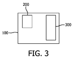
図2Bには、発信者ノードAと宛先ノードBとの間のユークリッド距離dが示されている。如何なる2つのノード10の間においても、ユークリッド距離が2点間の幾何学的距離として定義される。ノード10のネットワークアドレスが、対応するノード10のGPS位置に基づくものである場合、GPSに基づいた距離を使用することもできる。この場合、2つのノード10間の距離は、これらノードのGPS位置の間の距離として定義される。特に、当該ネットワークのノード10がネットワーク領域上に均等に分布されている場合、2つのノード間のユークリッド距離又はGPSに基づく距離は、2つのノードの間でデータパケットを伝送する場合に平均的に実行されるホップ数を、従って伝送時間を特徴とし得る。他の例として、該距離は当該データパケットが進行した実際の距離を示し得る。屋外照明ネットワークでは、ユークリッド距離よりも、街路に沿って測定される距離を使用することができる。何故なら、データパケットは、これらの経路に沿って進行しそうであるからである。これが、図2Cに示されており、街路に沿って配置された街路照明器具ノード10を図示している。このように、2つの照明器具ノード10間の距離は、道路網の街路に沿った空間距離又はホップ距離として定義される街路距離も示すことができる。図3には、本発明による装置100が示されている。該装置100は、例えば照明システムの照明器具に対する、無線マルチホップ網目状ネットワークのデータ収集器ノード50又はノード10と関連付けることができる。装置100は制御ユニット200を有する。更に、ノード10若しくは50又は装置100は、例えば無線周波数伝送により、無線通信経路40を介してデータパケットを送信又は受信するための送受信ユニット300を有する。装置100の制御ユニット200は、データパケット伝送における機能に従って異なるレイヤに分割することができる。例えば、OSIレイヤモデルを使用する場合、制御ユニット200は、当該装置100の伝送媒体との相互作用を定義するための物理レイヤ、マルチノードネットワークにおけるアドレス指定及びチャンネルアクセス制御メカニズムを提供するMACレイヤ、例えばネットワーク経路指定機能等の複数の機能及び手順を提供するネットワークレイヤ、例えばフロー制御、分割(セグメンテーション)/結合(デセグメンテーション)又はエラー制御等を用いて一層高いプロトコルレイヤに信頼性のあるデータ伝送サービスを提供するトランスポートレイヤ、及び通信相手を識別し、資源の利用可能性を判断し又は通信を同期させるためのアプリケーションレイヤを有するであろう。
FIG. 2B shows the Euclidean distance d between the sender node A and the destination node B. Between any two
マルチホップネットワークにおいては、如何なるノード10も、受信されたデータパケットを次の中間ノードNiに又は最終宛先ノードBに転送する中間ノードNiとして動作することができる。長距離を進行したデータパケットが中間ノードNiで失われた場合、このデータパケットは該データパケットの発信者ノードAにより再送信されねばならず(エンドツーエンド再送信)、このことは累積終端間遅延及びネットワーク資源(即ち、システム帯域幅)の消費を少なくとも倍化する。従って、本発明の一実施例によれば、転送されるべきデータパケットを処理するための伝送パラメータが中間ノードNiにおいて当該データパケットの進行した距離に基づいて調整されるようにすることが提案される。
In a multi-hop network, any
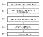
図4には、転送されるべきデータパケットのための伝送パラメータの調整を解説するフローチャートが示されている。ステップS40では、中間ノードNiにおいて発信者ノードA又は他の中間ノードNiの何れかからデータパケットが受信される。該データパケットを受信した後、該受信した中間ノードNiと発信者ノードAとの間の距離が決定される(ステップS41)。この距離に基づいて、当該データパケットの伝送パラメータが調整される(ステップS42)と共に、これら伝送パラメータを用いて該データパケットが処理される(ステップS43)。この処理は、長距離を進行したデータパケットが一層速く処理され得るように、例えばデータパケット待ち行列の順番、優先順位パラメータ等に影響を与えることができる。次いで、該データパケットは、上記の決定された伝送パラメータを用いて次のノード10に転送される(ステップS44)。
FIG. 4 shows a flowchart illustrating the adjustment of transmission parameters for a data packet to be transferred. In step S40, the intermediate node Ni receives a data packet from either the originator node A or another intermediate node Ni. After receiving the data packet, the distance between the received intermediate node Ni and sender node A is determined (step S41). Based on this distance, the transmission parameter of the data packet is adjusted (step S42), and the data packet is processed using the transmission parameter (step S43). This process can affect, for example, the order of data packet queues, priority parameters, etc. so that data packets traveling over long distances can be processed faster. Next, the data packet is transferred to the
上記伝送パラメータは、MACパラメータ、例えばMACレイヤ再送信の最大数、チャンネルアクセス試行の最大数、送信パワーレベル、再送信のための遅延時間若しくはチャンネルアクセスのためのバックオフ期間、又はこれらの組み合わせを指すことができる。上記MACレイヤ再送信の最大数は、どれくらい頻繁にMACレイヤがデータパケットの送信を再試行することを許されるかを決定する。同様に、上記チャンネルアクセス試行の最大数は、データパケットの送信のためにチャンネルアクセスを得るべくMACレイヤがキャリア検知を実行することを許される最大許容回数に関するものである。上記送信パワーレベルは、当該データパケットが転送されるために使用される送信エネルギを指し、従って該データパケットの信号強度に強く関係する。上記再送信のための遅延時間は、データパケットの連続する送信試行の間の遅延を指し、上記チャンネルアクセスのためのバックオフ期間は2つの連続するチャンネルアクセス試行の間の期間を示す。このように、上記伝送パラメータは、長距離を進行したデータパケットが宛先への最終的なホップを成功裏に通過する確率が増加されるように調整することができる。例えば、MACレイヤ再送信の最大数若しくはチャンネルアクセス試行の最大数若しくは送信パワーレベルを増加させることができるか、又は再送信のための遅延時間若しくはチャンネルアクセスのためのバックオフ期間を減少させることができる。勿論、これらの調整の組み合わせを選択することもできる。この手段により、恐らくは一層短い距離しか進行していないデータパケットを犠牲にして、多くのネットワーク帯域幅を既に使用した長距離を進行したデータパケットに対する成功率を増加させることができ、長い経路に対する全通信遅延を減少させることができる。従って、更に終端間通信遅延の内在的均一化も存在することになる。 The transmission parameters include MAC parameters such as maximum number of MAC layer retransmissions, maximum number of channel access attempts, transmission power level, delay time for retransmission or backoff period for channel access, or a combination thereof. Can point. The maximum number of MAC layer retransmissions determines how often the MAC layer is allowed to retry sending data packets. Similarly, the maximum number of channel access attempts is related to the maximum allowable number of times that the MAC layer is allowed to perform carrier detection to gain channel access for data packet transmission. The transmission power level refers to the transmission energy used to transfer the data packet and is therefore strongly related to the signal strength of the data packet. The delay time for retransmission refers to the delay between successive transmission attempts of data packets, and the backoff period for channel access indicates the period between two consecutive channel access attempts. Thus, the transmission parameters can be adjusted to increase the probability that a data packet that has traveled long distances will successfully pass the final hop to the destination. For example, the maximum number of MAC layer retransmissions or the maximum number of channel access attempts or transmission power level can be increased, or the delay time for retransmissions or the backoff period for channel access can be decreased. it can. Of course, a combination of these adjustments can also be selected. This measure can increase the success rate for data packets that have traveled long distances that already use a lot of network bandwidth, possibly at the expense of data packets that have traveled only a shorter distance, and can increase the overall rate for long paths. Communication delay can be reduced. Therefore, there is also an inherent equalization of end-to-end communication delay.
中間ノードNiは、当該データパケットが進行した距離を、該中間ノードに記憶されたローカルな情報又は該データパケットに含まれる情報に基づいて決定することができる。2つのノード間の距離は、ホップ距離、GPSに基づく距離又はユークリッド距離等の測定基準を用いて定義することができる。ノード10の位置が既知である場合、又はネットワークアドレスが対応ノード10のGPS位置に基づいている場合、これらから距離情報を導出することができる。他の例として、距離は、発信者ノードAと当該中間ノードNiとの間のホップ距離に基づいて導出することもできる。ホップ距離は、データパケットが発信者ノードAから進んだホップの数(ホップカウント)により特徴付けられる。幾つかの場合においては、例えばホップカウントの測定基準による経路指定テーブルを用いる場合のように、ホップ距離情報はネットワークレイヤで既に利用可能である。この場合、中間ノードNiには、発信者ノードAが該中間ノードNiからの対応する距離と一緒に記憶される。
The intermediate node Ni can determine the distance traveled by the data packet based on local information stored in the intermediate node or information included in the data packet. The distance between two nodes can be defined using metrics such as hop distance, GPS based distance or Euclidean distance. If the position of the
距離情報は、例えばネットワークレイヤにより、データパケット内に含まれる生存時間カウンタ(time-to-live
counter)又はホップカウンタを用いて明示的に発生することもできる。データパケットに含まれるホップカウンタは、発信者ノードAから宛先ノードBまでのマルチホップ伝送の間において各ホップで増加される。この場合、中間ノードNiはホップ距離情報を該ホップカウンタから、即ちホップカウントから導出することができる。ここで、上記ホップカウントは、発信者ノードAから受信された最後のn個のデータパケットに対する平均の(mean)又は平均的(average)ホップカウントに関係するものとすることもできる。代わりに、ホップカウントは、発信者ノードAから受信された最後のn個のデータパケットにおける最大ホップカウント又は最後のn個のデータパケットのホップカウントの時間にわたるスライディングウインドウ平均として選択することもできる。斯かるホップカウント情報は、この発信者ノードAに関するホップ距離を決定するためにネットワークレイヤで記憶することができる。
The distance information is obtained by, for example, a life-time counter (time-to-live) included in the data packet by the network layer.
counter) or hop counters can also be used to generate explicitly. The hop counter included in the data packet is incremented at each hop during multi-hop transmission from source node A to destination node B. In this case, the intermediate node Ni can derive the hop distance information from the hop counter, that is, from the hop count. Here, the hop count may be related to a mean or average hop count for the last n data packets received from the caller node A. Alternatively, the hop count may be selected as the sliding window average over the time of the maximum hop count in the last n data packets received from originator node A or the hop count of the last n data packets. Such hop count information can be stored at the network layer to determine the hop distance for this caller node A.
同様に、生存時間カウンタを使用することもできる。一般的に、生存時間カウンタ(TTL)は、最大所要ホップ数より大きな初期値を伴うヘッダフィールドである。各中間ノードNiにおいて、即ち各ホップの後、生存時間カウンタは減少される。ゼロなる現生存時間カウンタを持つデータパケットは、配信不能なデータパケットの無限の転送を防止するために破棄されるであろう。このように、ホップカウントは、最初のホップ以前の初期生存時間カウントと当該データパケットを受信した際の最終生存時間カウントとの間の差から導出することができる。ここで、中間ノードNiが生存時間カウンタの初期値を知っているか、又は初期生存時間カウントがデータパケットに埋め込まれるかの何れかである。他の例として、当該中間ノードのローカルなクロック信号を、発信者ノードAにおける送信の開始を示す開始時間又は送信タイムスタンプと比較されるべき基準として使用することができる。この手段により、進行した時間を、従って平均伝送速度を使用する場合は当該データパケットが進行した距離も導出することができる。勿論、距離情報及び特にホップカウント情報は、経路指定テーブルを構築する(例えば定期的にビーコンメッセージを送出することにより)ための他の技術を用いて発生することもできる。 Similarly, a survival time counter can be used. In general, the lifetime counter (TTL) is a header field with an initial value larger than the maximum required hop count. At each intermediate node Ni, ie after each hop, the lifetime counter is decremented. Data packets with a current lifetime counter of zero will be discarded to prevent infinite transfer of undeliverable data packets. Thus, the hop count can be derived from the difference between the initial lifetime count before the first hop and the final lifetime count when the data packet is received. Here, either the intermediate node Ni knows the initial value of the survival time counter or the initial survival time count is embedded in the data packet. As another example, the local node's local clock signal can be used as a reference to be compared to a start time or a transmission timestamp indicating the start of transmission at originator node A. By this means, it is also possible to derive the time traveled and thus the distance traveled by the data packet when using the average transmission rate. Of course, distance information, and in particular hop count information, can also be generated using other techniques for building a routing table (eg by sending out beacon messages periodically).
このように、中間ノードNiは、データパケットが進行した距離を、例えばホップカウンタ又は当該データパケットに含まれる発信者アドレスに基づいて識別することができる。長距離を進行したデータパケットは、大きなホップカウント値を、又は発信者ノードAのGPS位置(例えば、発信者アドレスフィールドに示される)と当該中間ノードNiのGPS位置(少なくとも該中間ノードNiによりローカルに分かる)との間の大きな差を示す。他の例として、進行されるべき距離、即ち発信者ノードAと宛先ノードBとの間の距離は、当該データパケットに含まれ得る。中間ノードNiと宛先ノードBとの間のローカルに分かる距離を用いて、進行した距離は、発信者ノードAと宛先ノードBとの間の距離から、該中間ノードNiと宛先ノードBとの間の上記距離を減算した距離として計算することができる。従って、有利な伝送パラメータを用いることにより斯様な長距離を進行したデータパケットを優先させれば、終端間遅延を、可能な最小値の近くまで低減することができる共に、当該ネットワークにわたって均一化することができる。更に、転送されるべき受信された各データパケットに対して、進行した距離が新たに決定される場合、上記伝送パラメータの調整は、或る発信者ノードAからのホップ数が変化し得る動的経路指定プロトコルにも適用することができる。 Thus, the intermediate node Ni can identify the distance traveled by the data packet based on, for example, the hop counter or the sender address included in the data packet. A data packet that has traveled long distances has a large hop count value, or the GPS location of the originator node A (for example, indicated in the originator address field) and the GPS location of the intermediate node Ni (locally at least by the intermediate node Ni). Shows a big difference. As another example, the distance to be traveled, i.e., the distance between originator node A and destination node B, may be included in the data packet. Using the locally known distance between the intermediate node Ni and the destination node B, the distance traveled can be determined from the distance between the originator node A and the destination node B between the intermediate node Ni and the destination node B. Can be calculated as a distance obtained by subtracting the above distance. Therefore, if data packets that have traveled over such long distances are prioritized by using advantageous transmission parameters, the end-to-end delay can be reduced to near the minimum possible value and can be made uniform across the network. can do. Furthermore, if the distance traveled is newly determined for each received data packet to be transferred, the adjustment of the transmission parameter is a dynamic that can change the number of hops from a certain originator node A. It can also be applied to routing protocols.
一例において、中間ノードNiには少なくとも2組の伝送パラメータが記憶され、一方のものはデータパケットの通常の処理又は転送に関するものであり、他方のものは優先された処理又は転送に関するものである。データパケットが進行した距離が或る閾値を越えると判断された場合、次のノード10に対する当該データパケットのホップのために優先的な伝送パラメータが選択される。このことは、例えば当該データパケットにフラグを設定することにより示すことができる。勿論、上記伝送パラメータは2より多いレベルで調整することもできる。他の例として、伝送パラメータの調整は、当該データパケットが進行した距離に比例させることもできる。更に、当該データパケットのタイプを、伝送パラメータの調整に影響を与える追加のパラメータとして決定することもできる。例えば、長距離を進行した時間の厳しいデータパケットに対する伝送パラメータは、より短い距離を進行した時間の厳しくないデータパケットよりも処理及び転送を特別に加速するような一層有利な伝送パラメータに調整することができる。可能性として、当該データパケットに含まれる優先順位さえも、伝送パラメータの調整のために考慮することができる。結果的に、長距離を進行したデータパケットは、より短い距離を進行したデータパケットよりも、次のノード10へ一層成功裏にホップしそうである。このことは、短い距離しか進行していないデータパケットを犠牲にして生じさせ、これにより、遅延が均一化される。
In one example, the intermediate node Ni stores at least two sets of transmission parameters, one relating to normal processing or forwarding of data packets and the other relating to prioritized processing or forwarding. If it is determined that the distance traveled by the data packet exceeds a certain threshold, a preferential transmission parameter is selected for the hop of the data packet for the
このことは、屋外照明システムのテレマネージメントに適用された場合、照明器具ノード10の同期を向上させる。何故なら、これら照明器具ノード10は命令を同等の遅延で受信するだろうからである。更に、如何なるデータ収集器ノード50(又は制御センタ60)からも遠く離れている照明器具ノード10に対する平均及び最大通信遅延も減少され、結果として同一のネットワーク内の照明器具ノード10に対し、より高い通信遅延の均一性が得られる。
This improves the synchronization of the
終端間通信遅延が増加する他の理由は、伝送が失敗した場合における終端間再送信の間の不必要な遅延である。一般的に、応答タイムアウト(answer time-out)は終端間通信遅延を最小にするために可能な限り小さな値をとるべきである。応答タイムアウトとは、如何なる発信者ノードAも、送信されたデータパケットに対する宛先ノードBからの応答を、該データパケットを再送信するまで待つ期間を指す。該応答は、発信者ノードAにより送られたデータパケットの成功裏の伝送を示すアクノレッジ又は発信者ノードAにより要求されたデータ又はこれら両方を含むことができる。応答がアクノレッジを含む場合、上記応答タイムアウトはアクノレッジ・タイムアウトとも称される。従来技術において、アクノレッジ・タイムアウトは一定であり、全てのノード10に対して共通である。従って、近隣のノード10に対する通信遅延は遠隔ノード10に対するものと等しく、恐らくは、データパケット再送信の不必要な遅延を生じさせる。本発明の他の実施例によれば、データパケットに対する応答タイムアウトは、アクノレッジ・タイムアウトを調整する例を用いた図5に示されるように、当該データパケットが進行すべき距離、即ち発信者ノードAと宛先ノードBとの間の距離に基づいて調整される。送信されるべきデータパケットを処理する場合、又はデータパケットを送信する場合(ステップS50)、発信者ノードAと宛先ノードBとの間の距離が決定される(ステップS51)。この距離に基づいて、当該データパケットに対するアクノレッジ・タイムアウトが調整される(ステップS52)。恐らくは、当該データパケットの優先度も考慮に入れられる。従って、アクノレッジがない場合のトランスポート/アプリケーションレイヤの再送信が、それに応じて予定される。本発明により提案されるように、個々の発信者/宛先の組み合わせに対してアクノレッジ・タイムアウトを調整する場合、発信者ノードAのアクノレッジ・タイムアウトを最適化することができ、かくして、終端間通信遅延を最小化する。アクノレッジ・タイムアウトの最小値は、発信元ノードと宛先ノードとの間のデータパケット伝送に関する予測される又は平均の往復時間、即ち当該データパケットの配信のための時間にアクノレッジの配信のための時間を加えたものに等しい。他の例として、応答タイムアウトの最小値は、往復時間等の最小値に設定することもできる。発信者ノードAが、送信したデータパケットに対するアクノレッジをアクノレッジ・タイムアウト内に受信しなかった場合、発信者ノードAは該データパケットを再送信する(ステップS53)。上記ステップの順序は変更することができる。即ち、ステップS51及び/又はS52は、データパケットを送信する(ステップS50)前に実行することもできる。
Another reason for increasing end-to-end communication delay is unnecessary delay during end-to-end retransmission in case of transmission failure. In general, the response time-out should be as small as possible to minimize end-to-end communication delay. The response timeout refers to a period during which any caller node A waits for a response from the destination node B to the transmitted data packet until the data packet is retransmitted. The response may include an acknowledgment indicating successful transmission of a data packet sent by originator node A, data requested by originator node A, or both. If the response includes an acknowledgement, the response timeout is also referred to as an acknowledge timeout. In the prior art, the acknowledge timeout is constant and is common to all
発信者ノードAは宛先ノードBまでの距離を、例えば経路指定テーブル、可能性のある宛先ノードまでの距離のリスト又は宛先ノードBから以前に受信された距離情報等の、該発信者ノードAに記憶されたデータの何れかから決定することができる。データパケットにホップカウンタ又は生存時間カウンタが含まれる場合、発信者ノードAは宛先ノードBまでの距離を、宛先ノードBから受信されるデータパケットに含まれるホップカウンタ又は生存時間カウンタから決定することができる。このように、宛先ノードBから受信されるデータパケットから導出されるホップカウント又は最後のn個のデータパケットから導出される平均若しくは最大ホップカウントを、逆経路のために用いることができる。 Caller node A provides the distance to destination node B to caller node A, such as a routing table, a list of possible distances to the destination node, or distance information previously received from destination node B, etc. It can be determined from any of the stored data. If the data packet includes a hop counter or a lifetime counter, caller node A may determine the distance to destination node B from the hop counter or lifetime counter included in the data packet received from destination node B. it can. Thus, the hop count derived from the data packet received from the destination Node B or the average or maximum hop count derived from the last n data packets can be used for the reverse path.
ホップカウントの尺度を選択する場合、アクノレッジ・タイムアウトは、time_out=2*定数*hop_count*hop_timeとして計算することができ、ここで、上記定数は1より大である。上記の2なる因数は、往復のためである。何故なら、ホップカウントは片道にだけ関するものであるからである。他の例として、往復のためのホップカウントを代わりに用いることもできる。従って、アクノレッジ・タイムアウトは平均往復時間より大きいか等しい。上記hop_timeは、マルチホップ伝送においてデータパケットを次の中間ノードNiに転送するために平均的に要する平均期間に関するものであり得る。これは、ネットワークにとり特徴的なものであり得る。ここでも、ホップ時間は、例えば当該データパケットが時間的に厳しい若しくは時間的に厳しくないデータパケットであるか、又は当該データパケットが高い若しくは低い優先度を付されているか等の、当該データパケットのタイプに依存し得る。勿論、上記hop_timeは、例えば中間ホップ時間(medium hop time)又はホップのうちの特定のパーセンテージ(例えば、90%〜99%)のものが成功裏になされる期間である成功ホップ時間等の他の特徴的時間により置換することもできる。GPSに基づく距離又はユークリッド距離を用いる場合、アクノレッジ・タイムアウトは選択された測定基準に関する特徴的時間を用いて同様に計算することができる。 When choosing a hop count measure, the acknowledge timeout can be calculated as time_out = 2 * constant * hop_count * hop_time, where the constant is greater than one. The above factor of 2 is for reciprocation. This is because the hop count is only for one way. As another example, a round trip hop count could be used instead. Thus, the acknowledge timeout is greater than or equal to the average round trip time. The hop_time may relate to an average period required on average to transfer a data packet to the next intermediate node Ni in multihop transmission. This can be characteristic for the network. Here again, the hop time is, for example, whether the data packet is severe in time or not severe in time, or whether the data packet is given a high or low priority. Can depend on type. Of course, the hop_time may be another hop time such as a medium hop time or a successful hop time during which a certain percentage of hops (eg, 90% to 99%) is successfully made. It can also be replaced by a characteristic time. When using GPS-based distances or Euclidean distances, the acknowledgment timeout can be similarly calculated using the characteristic time for the selected metric.
応答タイムアウトを調整するために、宛先ノードBにおける幾らかの遅延、例えば応答データパケットがバッファリングされるバッファ時間又は宛先ノードBから発信者ノードAへの方向転換時間等を考慮に入れることも可能である。 To adjust the response timeout, it is also possible to take into account some delay at the destination node B, such as the buffer time when the response data packet is buffered or the turnaround time from the destination node B to the source node A It is.
好ましくは、応答タイムアウトは、付加的に、結果的に大きなホップ時間となる当該ネットワークにおける現トラフィック負荷にも依存するものとすることができる。これは、例えば発信者ノードAにより観察され若しくは受信されるネットワークトラフィックの量により、又は発信者ノードAが最後の期間Tにおいてどれだけ多くのパケットを送出したかにより決定することができる。他の例として、受信者ノードB(又は中間ノードNiの何れか)は、発信者ノードAにネットワーク負荷に関する情報を例えばデータパケットの一部として又はアクノレッジと一緒に報告することができる。また、伝送パラメータがデータパケットの進行した距離に基づいて調整される場合、これを、応答タイムアウトの調整のために付加的に考慮することができる。 Preferably, the response timeout may additionally depend on the current traffic load in the network resulting in a large hop time. This can be determined, for example, by the amount of network traffic observed or received by caller node A, or by how many packets caller node A sent in the last period T. As another example, the recipient node B (or any of the intermediate nodes Ni) can report information about the network load to the originator node A, for example, as part of a data packet or with an acknowledgement. Also, if the transmission parameters are adjusted based on the distance traveled by the data packet, this can be additionally taken into account for adjusting the response timeout.
伝送パラメータ又は応答タイムアウトを調整することは、1つだけの宛先ノードBへ送られるユニキャストデータパケットにのみ適用可能であるということではない。当該実施例は、データパケットが幾つかの宛先ノードBに伝送されるブロードキャスト及びマルチキャストの場合にも適用可能である。これらの場合において、マルチキャスト群における異なる宛先ノードBに対しては異なる組みの伝送パラメータ又は異なる応答タイムアウトを考慮に入れることができ、例えば当該群内のノードに対する最大アクノレッジ・タイムアウトが選択される。 Adjusting transmission parameters or response timeouts is not only applicable to unicast data packets sent to only one destination Node B. This embodiment is also applicable to broadcast and multicast cases where data packets are transmitted to several destination Node Bs. In these cases, different sets of transmission parameters or different response timeouts can be taken into account for different destination Node Bs in the multicast group, for example the maximum acknowledge timeout for the nodes in the group is selected.
複数の照明器具ノード10を備えた大きな照明システムに適用される場合、操作コマンドに対する遅延は、このようにして最小化することができる。特に、操作コマンドを送信するデータ収集器ノード50(又は制御センタ60)から遠く離れており、既に長い伝送時間を有する照明器具ノード10に対しては、このことは、アクノレッジされないデータパケットの再送信の間の不必要な通信遅延を除去することになる。従って、斯かる照明システムの拡張可能性は更に向上され得ると共に、照明器具ノード10の応答時間を低減することができる。
When applied to a large lighting system with
従って、本発明によれば、ノード10が受信されたデータパケットを転送する中間ノードNiとして動作する場合、該中間ノードNiの伝送パラメータは、このデータパケットが進行した距離に基づいて調整することができる。この手段により、長距離を進行したデータパケットの生存機会は増加され、従って終端間通信遅延を減少させる。更に、データパケットは必要とされるホップ数とは無関係に同等の遅延を感受し、これはアプリケーション及びトランスポートレイヤにとっても有益である。このことは、データパケットが失われた場合にデータパケットを一層高いレイヤで再送信しなければならない場合に特に有効である。従って、当該ネットワークにおいて低減された平均及び最大遅延並びに一層高い遅延の均一性を達成することができる。加えて、ノード10が発信者ノードAとして動作する場合、応答タイムアウトを発信者ノードAと宛先ノードBとの個々の対に対して調整することができ、無線ネットワークにおいて終端間伝送遅延を更に低減することになる。このように、全体のネットワーク資源を節約することができる。
Therefore, according to the present invention, when the
Claims (15)
中間ノードにより受信されたデータパケットを転送するために該中間ノードの伝送パラメータを、前記データパケットが進行した該中間ノードと発信者ノードとの間の距離に基づいて調整する制御ユニット、
を有し、前記伝送パラメータが、前記データパケットが進行した前記距離が所定の閾値を越えたと判断された場合に前記データパケットに対する優先的伝送パラメータに設定され、前記伝送パラメータが前記データパケットのタイプに依存して調整されることを特徴とする装置。 An apparatus for controlling transmission of data packets in a wireless network having a plurality of nodes, wherein the plurality of nodes are luminaire nodes,
A control unit for adjusting the transmission parameters of the intermediate node based on the distance between the intermediate node and the originator node on which the data packet traveled in order to forward the data packet received by the intermediate node;
And the transmission parameter is set as a preferential transmission parameter for the data packet when it is determined that the distance the data packet has traveled exceeds a predetermined threshold, and the transmission parameter is the type of the data packet A device characterized by being adjusted depending on.
制御センタと、
複数のノードであって、これらノードのうちの少なくとも幾つかが請求項1ないし12の何れか一項に記載の装置を有するノードと、
を有し、前記無線ネットワークにおいてデータパケットが発信者ノードから宛先ノードへ中間ノードを介してマルチホップ伝送により伝送されるシステム。 A system for controlling transmission of data packets in a wireless network,
A control center;
A plurality of nodes, at least some of which have the device according to claim 1,
And a system in which data packets are transmitted by multi-hop transmission from an originator node to a destination node via an intermediate node in the wireless network.
中間ノードにおいてデータパケットを受信するステップと、
伝送パラメータを、前記データパケットが進行した前記中間ノードと発信者ノードとの間の距離に基づいて調整するステップと
前記データパケットを前記の調整された伝送パラメータに基づいて処理するステップと、
前記データパケットを転送するステップと、
を有し、前記伝送パラメータが、前記データパケットが進行した前記距離が所定の閾値を越えたと判断された場合に該データパケットに対する優先的伝送パラメータに設定され、前記伝送パラメータが前記データパケットのタイプに依存して調整されることを特徴とする方法。 A method of controlling transmission of data packets in a wireless network having a plurality of nodes, wherein the plurality of nodes are luminaire nodes, the method comprising:
Receiving a data packet at an intermediate node;
Adjusting transmission parameters based on the distance between the intermediate node and the originator node on which the data packet traveled; processing the data packets based on the adjusted transmission parameters;
Forwarding the data packet;
And the transmission parameter is set as a preferential transmission parameter for the data packet when it is determined that the distance traveled by the data packet exceeds a predetermined threshold, and the transmission parameter is the type of the data packet A method characterized in that it is adjusted depending on.
Applications Claiming Priority (3)
| Application Number | Priority Date | Filing Date | Title |
|---|---|---|---|
| EP10185952.8 | 2010-10-01 | ||
| EP20100185952 EP2437440A1 (en) | 2010-10-01 | 2010-10-01 | Device and method for delay optimization of end-to-end data packet transmissions in wireless networks |
| PCT/IB2011/053940 WO2012042411A1 (en) | 2010-10-01 | 2011-09-09 | Device and method for delay optimization of end-to-end data packet transmissions in wireless networks |
Publications (3)
| Publication Number | Publication Date |
|---|---|
| JP2013543692A JP2013543692A (en) | 2013-12-05 |
| JP2013543692A5 JP2013543692A5 (en) | 2014-10-23 |
| JP6118252B2 true JP6118252B2 (en) | 2017-04-19 |
Family
ID=43064852
Family Applications (1)
| Application Number | Title | Priority Date | Filing Date |
|---|---|---|---|
| JP2013530824A Active JP6118252B2 (en) | 2010-10-01 | 2011-09-09 | Apparatus and method for delay optimization of end-to-end data packet transmission in a wireless network |
Country Status (7)
| Country | Link |
|---|---|
| US (1) | US9119142B2 (en) |
| EP (2) | EP2437440A1 (en) |
| JP (1) | JP6118252B2 (en) |
| CN (1) | CN103119898B (en) |
| PL (1) | PL2622800T5 (en) |
| TW (1) | TW201218696A (en) |
| WO (1) | WO2012042411A1 (en) |
Cited By (1)
| Publication number | Priority date | Publication date | Assignee | Title |
|---|---|---|---|---|
| KR20190103843A (en) * | 2018-02-28 | 2019-09-05 | 주식회사 노비스텍 | Streetlight wireless remote monitoring and controlling system |
Families Citing this family (39)
| Publication number | Priority date | Publication date | Assignee | Title |
|---|---|---|---|---|
| US9241298B2 (en) * | 2011-11-18 | 2016-01-19 | Qualcomm Incorporated | Devices and methods for facilitating access probe sequences |
| KR101458852B1 (en) * | 2012-02-10 | 2014-11-12 | 폴리콤 인코포레이티드 | System and method for handling critical packets loss in multi-hop rtp streaming |
| JP6048502B2 (en) * | 2012-07-23 | 2016-12-21 | 富士通株式会社 | Communication device |
| CN104813639B (en) * | 2012-10-01 | 2017-05-17 | Abb研究有限公司 | Method and device for packet sending prioritizing in an industrial wireless network |
| CN103916448B (en) * | 2013-01-09 | 2018-05-18 | 深圳市腾讯计算机系统有限公司 | Data transmission method, system and corresponding cloud transmission platform based on cloud transmission platform |
| US9509636B2 (en) * | 2013-03-15 | 2016-11-29 | Vivint, Inc. | Multicast traffic management within a wireless mesh network |
| US8879613B1 (en) * | 2013-08-06 | 2014-11-04 | Cisco Technology, Inc. | Dynamic frame selection when requesting tone map parameters in mesh networks |
| JP6244744B2 (en) * | 2013-08-28 | 2017-12-13 | 株式会社リコー | COMMUNICATION DEVICE, COMMUNICATION METHOD, AND COMMUNICATION SYSTEM |
| US9712332B2 (en) | 2014-03-11 | 2017-07-18 | Vivint, Inc. | Node directed multicast traffic management systems and methods for mesh networks |
| WO2015167500A1 (en) * | 2014-04-30 | 2015-11-05 | Hewlett Packard Development Company, L.P. | Flood disable on network switch |
| US9923836B1 (en) * | 2014-11-21 | 2018-03-20 | Sprint Spectrum L.P. | Systems and methods for configuring a delay based scheduler for an access node |
| FR3030991B1 (en) * | 2014-12-22 | 2018-03-23 | Commissariat A L'energie Atomique Et Aux Energies Alternatives | NETWORK OF MEASURING DEVICES COMMUNICATING BY RADIO LINK |
| CN104734808B (en) * | 2015-03-07 | 2018-05-29 | 浙江理工大学 | Worst time delay perceives cross-layer optimizing method in a kind of wireless sensor network |
| DE102015207985A1 (en) * | 2015-04-30 | 2016-11-03 | Zumtobel Lighting Gmbh | Method and system for transmitting control commands for distributed units |
| CN104967813A (en) * | 2015-07-04 | 2015-10-07 | 马岩 | Video conference overtime retransmission method and system |
| KR102419647B1 (en) * | 2015-09-10 | 2022-07-11 | 삼성전자주식회사 | Apparatus and method for transmitting packets |
| CN105263121B (en) * | 2015-09-17 | 2018-10-12 | 重庆邮电大学 | Method for routing based on crossroad in a kind of chance In-vehicle networking |
| US10027581B2 (en) * | 2015-10-19 | 2018-07-17 | Cisco Technology, Inc. | Routing traffic over chaotic networks |
| CN105897582A (en) * | 2015-12-07 | 2016-08-24 | 乐视云计算有限公司 | Inter-node distance measurement method and system |
| US20170163509A1 (en) * | 2015-12-07 | 2017-06-08 | Le Holdings (Beijing) Co., Ltd. | Inter-node distance metric method and system |
| SE540352C2 (en) * | 2016-01-29 | 2018-07-24 | Icomera Ab | Wireless communication system and method for trains and other vehicles using trackside base stations |
| DE102016102525A1 (en) * | 2016-02-15 | 2017-08-17 | Hella Kgaa Hueck & Co. | Communication system for data communication with at least one vehicle in traffic |
| US9900079B2 (en) * | 2016-03-21 | 2018-02-20 | Cisco Technology, Inc. | Reliable connectionless low power coverage extension |
| JP6635866B2 (en) * | 2016-04-20 | 2020-01-29 | 大阪瓦斯株式会社 | Wireless communication system |
| GB2565987B (en) * | 2016-07-29 | 2021-08-18 | Motorola Solutions Inc | Wireless ad-hoc network flooding mechanism to intelligently locate required responders |
| US11234122B2 (en) * | 2016-08-10 | 2022-01-25 | Telefonaktiebolaget Lm Ericsson (Publ) | Packet forwarding in a wireless mesh network |
| US10673881B2 (en) * | 2016-08-11 | 2020-06-02 | Hopzero, Inc. | Method and system for limiting the range of data transmissions |
| DE102016125636A1 (en) * | 2016-12-23 | 2018-06-28 | Osram Gmbh | Operation of a transmitting device of a lighting device having a lighting device |
| EP3367613A1 (en) * | 2017-02-28 | 2018-08-29 | ABB Schweiz AG | System and method for improving latency in a wireless building automation network |
| EP3701657B1 (en) * | 2017-10-27 | 2022-08-03 | Telefonaktiebolaget LM Ericsson (PUBL) | Method and device for updating the number of retransmissions in a wireless mesh network |
| CN109905897B (en) * | 2017-12-08 | 2022-11-18 | 华为技术有限公司 | Data transmission method and device |
| US10944669B1 (en) | 2018-02-09 | 2021-03-09 | GoTenna, Inc. | System and method for efficient network-wide broadcast in a multi-hop wireless network using packet echos |
| EP3831021A1 (en) | 2018-07-27 | 2021-06-09 | Gotenna Inc. | VINEtm ZERO-CONTROL ROUTING USING DATA PACKET INSPECTION FOR WIRELESS MESH NETWORKS |
| CN109039906B (en) * | 2018-10-24 | 2020-10-30 | 常熟理工学院 | Routing implementation method of intelligent Internet of vehicles |
| US10754559B1 (en) * | 2019-03-08 | 2020-08-25 | EMC IP Holding Company LLC | Active-active storage clustering with clock synchronization |
| US10602402B1 (en) * | 2019-08-28 | 2020-03-24 | Ambit Microsystems (Shanghai) Ltd. | Method and system for adjusting packet length and mobile device using the method |
| JP7364539B2 (en) * | 2020-08-03 | 2023-10-18 | 本田技研工業株式会社 | Network management device, network management method, and program |
| US11758367B2 (en) * | 2021-05-10 | 2023-09-12 | Cisco Technology, Inc. | Multicast tree topology having multicast hubs for different multicast areas in a Wi-SUN FAN data network |
| CN113938859B (en) * | 2021-12-13 | 2022-03-15 | 深圳市永达电子信息股份有限公司 | Integrated system and method for centralized and decentralized communication for mobile devices |
Family Cites Families (30)
| Publication number | Priority date | Publication date | Assignee | Title |
|---|---|---|---|---|
| DE19849294C2 (en) * | 1998-10-16 | 2001-09-27 | Daimler Chrysler Ag | Method of spreading a message |
| US6405337B1 (en) | 1999-06-21 | 2002-06-11 | Ericsson Inc. | Systems, methods and computer program products for adjusting a timeout for message retransmission based on measured round-trip communications delays |
| JP3539338B2 (en) * | 2000-03-23 | 2004-07-07 | 日本電気株式会社 | Priority data transfer method |
| US6958998B2 (en) | 2001-07-09 | 2005-10-25 | International Business Machines Corporation | Traffic management in packet-based networks |
| US8571415B1 (en) * | 2001-07-19 | 2013-10-29 | Alcatel Lucent | Regenerators placement mechanism for wavelength switched optical networks |
| DE50112836D1 (en) * | 2001-10-02 | 2007-09-20 | Siemens Ag | A method and communication device for performing a distance-related quality of service in a communication system |
| JP4535661B2 (en) | 2002-03-18 | 2010-09-01 | 日本電気株式会社 | Transmission node, relay node and communication system in wireless multi-hop network |
| US8639251B2 (en) * | 2004-03-30 | 2014-01-28 | Telefonaktiebolaget Lm Ericsson (Publ) | Methods of and apparatuses for cell-differentiated handover in a mobile communications systems |
| US7466664B2 (en) * | 2005-09-02 | 2008-12-16 | Palo Alto Research Center Incorporated | Methods, apparatus, and program products for applying a visibility function to networked information |
| US7768926B2 (en) * | 2006-03-09 | 2010-08-03 | Firetide, Inc. | Effective bandwidth path metric and path computation method for wireless mesh networks with wired links |
| JP2007335943A (en) * | 2006-06-12 | 2007-12-27 | Nippon Telegr & Teleph Corp <Ntt> | Wireless base station and multihop control method |
| KR100789773B1 (en) * | 2006-12-08 | 2007-12-28 | 한국전자통신연구원 | A mesh networking auto configuration method, virtual link setting method, packet transmission method and terminal for its in multi hop wireless lan |
| JP2008167141A (en) * | 2006-12-28 | 2008-07-17 | Nec Corp | Data transmission method and device, and communication system using the same |
| KR100832519B1 (en) * | 2007-03-13 | 2008-05-26 | (주)에스디시스템 | Lighting control system using wireless tag and method thereof |
| KR20090056070A (en) * | 2007-11-29 | 2009-06-03 | 대구대학교 산학협력단 | Message broadcast method using contension window in vehicular ad-hoc network |
| WO2009071692A1 (en) | 2007-12-05 | 2009-06-11 | Thomson Licensing | Method for characterizing a communication link in a communication network |
| KR20090065230A (en) | 2007-12-17 | 2009-06-22 | 한국전자통신연구원 | Wireless sensor network having hierarchical structure and method for routing for the same |
| US8301955B2 (en) | 2008-01-15 | 2012-10-30 | Avaya Inc. | Method and apparatus performing express retransmission of frames |
| US8345607B2 (en) * | 2008-03-10 | 2013-01-01 | Marvell World Trade Ltd. | Coexistence and collocation of remote network and local network radios |
| ES2326949B1 (en) * | 2008-03-18 | 2010-07-14 | Clarity Systems, S.L. | PROCEDURE USED BY A STREAMING SERVER TO MAKE A TRANSMISSION OF A MULTIMEDIA FILE IN A DATA NETWORK. |
| CN101631357A (en) * | 2008-07-18 | 2010-01-20 | 中国移动通信集团公司 | Method, device and terminal for selective response packet transmission |
| US8483077B2 (en) * | 2009-09-16 | 2013-07-09 | At&T Intellectual Property I, L.P. | QoS in multi-hop wireless networks |
| CN101651963B (en) | 2009-07-09 | 2012-05-23 | 南京工业大学 | Transmission control method based on differentiated service in IEEE 802.11 WLAN |
| JP5589410B2 (en) * | 2010-01-29 | 2014-09-17 | 沖電気工業株式会社 | Communication system and communication apparatus |
| WO2011145027A1 (en) | 2010-05-21 | 2011-11-24 | Koninklijke Philips Electronics N.V. | Method and device for forwarding data packets |
| WO2012042426A1 (en) | 2010-10-01 | 2012-04-05 | Koninklijke Philips Electronics N.V. | Device and method for reliability enhancement for data packet transmissions in wireless networks |
| EP2437428A1 (en) | 2010-10-01 | 2012-04-04 | Koninklijke Philips Electronics N.V. | Device and method for load balancing for data packet transmissions in wireless networks |
| US10397823B2 (en) | 2010-10-01 | 2019-08-27 | Signify Holding B.V. | Device and method for scheduling data packet transmission in wireless networks |
| WO2012052804A1 (en) * | 2010-10-20 | 2012-04-26 | Nokia Corporation | Method and apparatus for adjacent channel emission limit |
| US20130155919A1 (en) * | 2011-12-20 | 2013-06-20 | Korea Basic Science Institute | Method of potential routing, method of potential scheduling, and mesh node |
-
2010
- 2010-10-01 EP EP20100185952 patent/EP2437440A1/en not_active Ceased
-
2011
- 2011-09-09 EP EP11764326.2A patent/EP2622800B2/en active Active
- 2011-09-09 CN CN201180046862.2A patent/CN103119898B/en active Active
- 2011-09-09 JP JP2013530824A patent/JP6118252B2/en active Active
- 2011-09-09 WO PCT/IB2011/053940 patent/WO2012042411A1/en active Application Filing
- 2011-09-09 PL PL11764326T patent/PL2622800T5/en unknown
- 2011-09-09 US US13/876,183 patent/US9119142B2/en active Active
- 2011-09-28 TW TW100135098A patent/TW201218696A/en unknown
Cited By (2)
| Publication number | Priority date | Publication date | Assignee | Title |
|---|---|---|---|---|
| KR20190103843A (en) * | 2018-02-28 | 2019-09-05 | 주식회사 노비스텍 | Streetlight wireless remote monitoring and controlling system |
| KR102107392B1 (en) * | 2018-02-28 | 2020-05-07 | 주식회사 노비스텍 | Streetlight wireless remote monitoring and controlling system |
Also Published As
| Publication number | Publication date |
|---|---|
| EP2622800A1 (en) | 2013-08-07 |
| EP2622800B2 (en) | 2020-03-18 |
| EP2622800B1 (en) | 2017-08-23 |
| CN103119898B (en) | 2016-04-13 |
| PL2622800T3 (en) | 2018-01-31 |
| EP2437440A1 (en) | 2012-04-04 |
| US9119142B2 (en) | 2015-08-25 |
| TW201218696A (en) | 2012-05-01 |
| WO2012042411A1 (en) | 2012-04-05 |
| JP2013543692A (en) | 2013-12-05 |
| US20130188562A1 (en) | 2013-07-25 |
| PL2622800T5 (en) | 2020-07-27 |
| CN103119898A (en) | 2013-05-22 |
Similar Documents
| Publication | Publication Date | Title |
|---|---|---|
| JP6118252B2 (en) | Apparatus and method for delay optimization of end-to-end data packet transmission in a wireless network | |
| JP5992421B2 (en) | Device and method for load balancing data packets in a wireless network | |
| JP6032754B2 (en) | Device and method for scheduling data packet transmission in a wireless network | |
| EP2643951B1 (en) | System and method for optimizing data transmission to nodes of a wireless mesh network | |
| KR101033720B1 (en) | Method and system for improving a wireless communication route | |
| EP2471311B1 (en) | Method and apparatus for determining rank of node in multi-hop wireless network | |
| EP2280517B1 (en) | Method and apparatus for controlling packet transmissions within wireless networks to enhance network formation | |
| Fussler et al. | A novel forwarding paradigm for position-based routing (with implicit addressing) | |
| WO2012140610A1 (en) | Hierarchical routing for wireless networks | |
| WO2012042454A1 (en) | Device and method for reducing delay of data packet transmissions in wireless networks | |
| WO2012042426A1 (en) | Device and method for reliability enhancement for data packet transmissions in wireless networks |
Legal Events
| Date | Code | Title | Description |
|---|---|---|---|
| A521 | Request for written amendment filed |
Free format text: JAPANESE INTERMEDIATE CODE: A523 Effective date: 20140904 |
|
| A621 | Written request for application examination |
Free format text: JAPANESE INTERMEDIATE CODE: A621 Effective date: 20140904 |
|
| RD02 | Notification of acceptance of power of attorney |
Free format text: JAPANESE INTERMEDIATE CODE: A7422 Effective date: 20140904 |
|
| A977 | Report on retrieval |
Free format text: JAPANESE INTERMEDIATE CODE: A971007 Effective date: 20150706 |
|
| A131 | Notification of reasons for refusal |
Free format text: JAPANESE INTERMEDIATE CODE: A131 Effective date: 20150721 |
|
| A601 | Written request for extension of time |
Free format text: JAPANESE INTERMEDIATE CODE: A601 Effective date: 20151020 |
|
| A521 | Request for written amendment filed |
Free format text: JAPANESE INTERMEDIATE CODE: A523 Effective date: 20160120 |
|
| A131 | Notification of reasons for refusal |
Free format text: JAPANESE INTERMEDIATE CODE: A131 Effective date: 20160704 |
|
| A711 | Notification of change in applicant |
Free format text: JAPANESE INTERMEDIATE CODE: A711 Effective date: 20160927 |
|
| A521 | Request for written amendment filed |
Free format text: JAPANESE INTERMEDIATE CODE: A523 Effective date: 20161003 |
|
| TRDD | Decision of grant or rejection written | ||
| A01 | Written decision to grant a patent or to grant a registration (utility model) |
Free format text: JAPANESE INTERMEDIATE CODE: A01 Effective date: 20170224 |
|
| A61 | First payment of annual fees (during grant procedure) |
Free format text: JAPANESE INTERMEDIATE CODE: A61 Effective date: 20170324 |
|
| R150 | Certificate of patent or registration of utility model |
Ref document number: 6118252 Country of ref document: JP Free format text: JAPANESE INTERMEDIATE CODE: R150 |
|
| S531 | Written request for registration of change of domicile |
Free format text: JAPANESE INTERMEDIATE CODE: R313531 |
|
| S533 | Written request for registration of change of name |
Free format text: JAPANESE INTERMEDIATE CODE: R313533 |
|
| R350 | Written notification of registration of transfer |
Free format text: JAPANESE INTERMEDIATE CODE: R350 |
|
| R250 | Receipt of annual fees |
Free format text: JAPANESE INTERMEDIATE CODE: R250 |
|
| R250 | Receipt of annual fees |
Free format text: JAPANESE INTERMEDIATE CODE: R250 |
|
| R250 | Receipt of annual fees |
Free format text: JAPANESE INTERMEDIATE CODE: R250 |
|
| R250 | Receipt of annual fees |
Free format text: JAPANESE INTERMEDIATE CODE: R250 |
|
| R250 | Receipt of annual fees |
Free format text: JAPANESE INTERMEDIATE CODE: R250 |