JP6117911B2 - Optimization of 3-stage folded CLOS for 802.1AQ - Google Patents
Optimization of 3-stage folded CLOS for 802.1AQ Download PDFInfo
- Publication number
- JP6117911B2 JP6117911B2 JP2015507625A JP2015507625A JP6117911B2 JP 6117911 B2 JP6117911 B2 JP 6117911B2 JP 2015507625 A JP2015507625 A JP 2015507625A JP 2015507625 A JP2015507625 A JP 2015507625A JP 6117911 B2 JP6117911 B2 JP 6117911B2
- Authority
- JP
- Japan
- Prior art keywords
- node
- network
- edge
- root
- nodes
- Prior art date
- Legal status (The legal status is an assumption and is not a legal conclusion. Google has not performed a legal analysis and makes no representation as to the accuracy of the status listed.)
- Active
Links
- 238000005457 optimization Methods 0.000 title description 2
- 238000001914 filtration Methods 0.000 claims description 33
- 238000000034 method Methods 0.000 claims description 28
- 238000012546 transfer Methods 0.000 claims description 22
- 230000006870 function Effects 0.000 claims description 10
- 238000004891 communication Methods 0.000 claims description 7
- 230000007480 spreading Effects 0.000 claims description 3
- 238000003892 spreading Methods 0.000 claims description 3
- 238000004364 calculation method Methods 0.000 description 11
- 230000007246 mechanism Effects 0.000 description 11
- 230000000903 blocking effect Effects 0.000 description 9
- 238000010586 diagram Methods 0.000 description 8
- 238000003860 storage Methods 0.000 description 5
- 238000009826 distribution Methods 0.000 description 4
- 230000006399 behavior Effects 0.000 description 3
- 230000008901 benefit Effects 0.000 description 3
- 230000005540 biological transmission Effects 0.000 description 3
- 230000008859 change Effects 0.000 description 3
- 230000006855 networking Effects 0.000 description 3
- 230000009471 action Effects 0.000 description 2
- 238000013459 approach Methods 0.000 description 2
- 230000003190 augmentative effect Effects 0.000 description 2
- 238000006243 chemical reaction Methods 0.000 description 2
- 238000013461 design Methods 0.000 description 2
- 239000004744 fabric Substances 0.000 description 2
- 230000006872 improvement Effects 0.000 description 2
- 230000000873 masking effect Effects 0.000 description 2
- 230000003287 optical effect Effects 0.000 description 2
- 238000012545 processing Methods 0.000 description 2
- 230000000644 propagated effect Effects 0.000 description 2
- ODCKICSDIPVTRM-UHFFFAOYSA-N [4-[2-hydroxy-3-(propan-2-ylazaniumyl)propoxy]naphthalen-1-yl] sulfate Chemical compound C1=CC=C2C(OCC(O)CNC(C)C)=CC=C(OS(O)(=O)=O)C2=C1 ODCKICSDIPVTRM-UHFFFAOYSA-N 0.000 description 1
- 238000003491 array Methods 0.000 description 1
- 230000009286 beneficial effect Effects 0.000 description 1
- 230000015556 catabolic process Effects 0.000 description 1
- 238000010276 construction Methods 0.000 description 1
- 238000006731 degradation reaction Methods 0.000 description 1
- 238000001514 detection method Methods 0.000 description 1
- 230000000694 effects Effects 0.000 description 1
- 238000005516 engineering process Methods 0.000 description 1
- 230000007717 exclusion Effects 0.000 description 1
- 230000010354 integration Effects 0.000 description 1
- 238000012986 modification Methods 0.000 description 1
- 230000004048 modification Effects 0.000 description 1
- 238000000926 separation method Methods 0.000 description 1
- 230000009466 transformation Effects 0.000 description 1
- 230000007704 transition Effects 0.000 description 1
- 230000005641 tunneling Effects 0.000 description 1
Images


Classifications
-
- H—ELECTRICITY
- H04—ELECTRIC COMMUNICATION TECHNIQUE
- H04L—TRANSMISSION OF DIGITAL INFORMATION, e.g. TELEGRAPHIC COMMUNICATION
- H04L45/00—Routing or path finding of packets in data switching networks
- H04L45/48—Routing tree calculation
-
- H—ELECTRICITY
- H04—ELECTRIC COMMUNICATION TECHNIQUE
- H04L—TRANSMISSION OF DIGITAL INFORMATION, e.g. TELEGRAPHIC COMMUNICATION
- H04L12/00—Data switching networks
-
- H—ELECTRICITY
- H04—ELECTRIC COMMUNICATION TECHNIQUE
- H04L—TRANSMISSION OF DIGITAL INFORMATION, e.g. TELEGRAPHIC COMMUNICATION
- H04L45/00—Routing or path finding of packets in data switching networks
- H04L45/48—Routing tree calculation
- H04L45/484—Routing tree calculation using multiple routing trees
-
- H—ELECTRICITY
- H04—ELECTRIC COMMUNICATION TECHNIQUE
- H04L—TRANSMISSION OF DIGITAL INFORMATION, e.g. TELEGRAPHIC COMMUNICATION
- H04L45/00—Routing or path finding of packets in data switching networks
- H04L45/12—Shortest path evaluation
-
- H—ELECTRICITY
- H04—ELECTRIC COMMUNICATION TECHNIQUE
- H04L—TRANSMISSION OF DIGITAL INFORMATION, e.g. TELEGRAPHIC COMMUNICATION
- H04L45/00—Routing or path finding of packets in data switching networks
- H04L45/16—Multipoint routing
-
- H—ELECTRICITY
- H04—ELECTRIC COMMUNICATION TECHNIQUE
- H04L—TRANSMISSION OF DIGITAL INFORMATION, e.g. TELEGRAPHIC COMMUNICATION
- H04L45/00—Routing or path finding of packets in data switching networks
- H04L45/24—Multipath
-
- H—ELECTRICITY
- H04—ELECTRIC COMMUNICATION TECHNIQUE
- H04L—TRANSMISSION OF DIGITAL INFORMATION, e.g. TELEGRAPHIC COMMUNICATION
- H04L45/00—Routing or path finding of packets in data switching networks
- H04L45/28—Routing or path finding of packets in data switching networks using route fault recovery
Description
本発明の実施形態は、コンピュータネットワーキングの分野に関し、より具体的には、3段折り返し(three stage folded)CLOSネットワークにおけるイーサネットルーティングの最適化に関する。 Embodiments of the present invention relate to the field of computer networking, and more specifically to optimizing Ethernet routing in a three stage folded CLOS network.
IEEE802.1aq標準(これ以降、802.1aqともいう)は、2012年に公開され、イーサネットのためのルーティングソリューションを定義している。802.1aqは、最短パスブリッジングあるいはSPBとしても知られている。802.1aqは、ネイティブなイーサネット基盤上での論理的なイーサネットネットワークの生成を可能とする。802.1aqは、トポロジー及びネットワーク内のノードの論理的なネットワークメンバシップの双方を広告するために、リンクステートプロトコルを採用する。データパケットは、802.1aqを実装するネットワークのエッジノードにおいて、mac−in−macの802.1ahフレーム又はタグ付き802.1Q/p802.1adフレームのいずれかでカプセル化され、論理ネットワークの他のメンバにのみ移送される。ユニキャスト及びマルチキャストもまた、802.1aqによりサポートされる。全てのそうしたルーティングは、対称的な最短パスを介して行われる。多くの等コストな最短パスがサポートされる。ネットワークにおける802.1aqの実装は、プロバイダネットワーク、企業ネットワーク及びクラウドネットワークを含む多様なタイプのネットワークの生成及び構成を簡素化する。構成は比較的簡素化され、エラーの可能性、特に人為的な構成エラーの可能性が減少する。 The IEEE 802.1aq standard (hereinafter also referred to as 802.1aq) was published in 2012 and defines a routing solution for Ethernet. 802.1aq is also known as shortest path bridging or SPB. 802.1aq allows creation of a logical Ethernet network on a native Ethernet infrastructure. 802.1aq employs a link state protocol to advertise both topology and logical network membership of nodes in the network. Data packets are encapsulated in either mac-in-mac 802.1ah frames or tagged 802.1Q / p802.1ad frames at the edge nodes of the network implementing 802.1aq, Only transferred to members. Unicast and multicast are also supported by 802.1aq. All such routing is done through a symmetric shortest path. Many equal cost shortest paths are supported. The implementation of 802.1aq in the network simplifies the creation and configuration of various types of networks, including provider networks, enterprise networks, and cloud networks. The configuration is relatively simplified, reducing the possibility of errors, especially the possibility of artificial configuration errors.
方法の一実施形態が、計算上の複雑さ、ネットワーク運営、マルチキャストアドレッシング、及び障害時の負荷再分配、についての改善された効率性を伴うイーサネットルーティングのために使用される3段折り返しCLOSネットワークにおいて実装される。上記ネットワークは、ユーザに面する(user-facing)入力及び出力ポートを有するエッジノードの配列に連結されるルートノードの配列を含む。上記ネットワーク内の各ノードは、上記ルートノードから発するスパニングツリーについての転送ステートを計算し及びインストールする。上記スパニングツリーにおけるデータ転送は、上記ネットワークに障害が無い場合には任意ソース(any source)のマルチキャストパスアドレスをマルチキャストパスのために利用する。これは、サービスに参加するノードの数とマルチキャストグループの数との積という組合せ積(combinatorial product)ではなく、マルチキャストグループの数に線型的に比例してスケーリングするためである。所与のルートノードへの障害を起こした接続を有するものとして所与のエッジノードが識別されると、上記ネットワーク内の各ノードは、上記所与のルートノードから発し上記障害を起こした接続を使用するスパニングツリーのための各B−VIDについての、上記所与のエッジノードから発する最短パス優先(SPF)ツリーを計算し、上記SPFツリーは、上記B−VIDについての上記所与のエッジノードへのユニキャスト及びマルチキャストの接続性のためのプロトタイプとして供される。上記所与のエッジノードと他のエッジノードとの間のペアごとの接続性のために、各ノード内のフィルタリングデータベースへデータが投入され(populated)、それらは移動される(displaced)B−VIDに関連付けられるサービスを共通して有する。そして、ノードは、上記フィルタリングデータベース内にユニキャストステートをインストールし、トラフィックが上記所与のエッジノードへと向かうのか上記所与のエッジノードから来るのかに依存して選択されるマルチキャストアドレッシングのハイブリッドを用いて、上記フィルタリングデータベース内にマルチキャストステートをもインストールする。そして、各ノードは、自身の転送データベースを用いて、上記ネットワークにおいてユニキャスト及びマルチキャストデータを転送する。 In a three-stage folded CLOS network where an embodiment of the method is used for Ethernet routing with improved efficiency for computational complexity, network operation, multicast addressing, and load redistribution in case of failure Implemented. The network includes an array of root nodes coupled to an array of edge nodes having user-facing input and output ports. Each node in the network calculates and installs a forwarding state for the spanning tree originating from the root node. Data transfer in the spanning tree uses a multicast path address of any source for the multicast path when there is no failure in the network. This is to scale linearly in proportion to the number of multicast groups, not a combinatorial product, which is the product of the number of nodes participating in the service and the number of multicast groups. When a given edge node is identified as having a failed connection to a given root node, each node in the network initiates the failed connection originating from the given root node. Compute a shortest path first (SPF) tree originating from the given edge node for each B-VID for the spanning tree to use, the SPF tree being the given edge node for the B-VID It serves as a prototype for unicast and multicast connectivity to. For pair-wise connectivity between the given edge node and other edge nodes, data is populated into the filtering database in each node and they are displaced B-VID Commonly have services associated with. The node then installs a unicast state in the filtering database and selects a hybrid of multicast addressing that is selected depending on whether traffic is destined for or from the given edge node. Used to install a multicast state in the filtering database. Each node transfers unicast and multicast data in the network using its own transfer database.
上述した実施形態は、分散型のルーティングシステムであり、各ノードがフィルタリングデータベース内の自身の転送テーブルを計算する。代替的な実施形態において、転送テーブルを計算するシステム管理機能を、集中型のコントローラが実行する。そして、転送テーブルは、各ノードへ、当該ノードがデータ転送を実行するためにダウンロードされる。 The embodiment described above is a distributed routing system where each node calculates its own forwarding table in the filtering database. In an alternative embodiment, the centralized controller performs the system management function that calculates the forwarding table. The transfer table is downloaded to each node so that the node can perform data transfer.
エッジノードとして機能するネットワークエレメントの一実施形態が、マルチキャストアドレッシング及び障害時の負荷再分配、についての改善された効率性を伴うイーサネットルーティングのために使用される3段折り返しCLOSネットワークにおいて実装される。上記エッジノードは、ユーザに面する入力及び出力ポートの第1のセットと、複数のルートノードへ連結される入力及び出力ポートの第2のセットと、フィルタリングデータベースを記憶するメモリと、ネットワークプロセッサと、を備える。上記ネットワークプロセッサは、上記ルートノードから発するスパニングツリーについての転送ステートを計算し及びインストールするように構成され、上記スパニングツリーにおけるデータ転送は、上記ネットワークに障害が無い場合には任意ソースのマルチキャストパスアドレスをマルチキャストパスのために利用し、上記ネットワークプロセッサは、所与のルートノードへの障害を起こした接続を有するものとして所与のエッジノードを識別し、上記所与のエッジノードから発するSPFツリーを、上記所与のルートノードから発し上記障害を起こした接続を使用するスパニングツリーのための各B−VIDについて構築するように構成され、上記SPFツリーは、上記所与のエッジノードへのユニキャスト及びマルチキャストの接続性のためのプロトタイプとして供されるものであり、上記ネットワークプロセッサは、移動される上記B−VIDに関連付けられるサービスを共通して有する上記所与のエッジノードと他のエッジノードとの間のペアごとの接続性のために、フィルタリングデータベースへデータ投入し、上記フィルタリングデータベース内にユニキャストステートをインストールし、トラフィックが上記所与のエッジノードへと向かうのか上記所与のエッジノードから来るのかに依存して選択されるマルチキャストアドレッシングのハイブリッドを用いて、上記フィルタリングデータベース内にマルチキャストステートをインストールする、ように構成される。そして、ネットワーク内のユニキャスト及びマルチキャストデータを転送するために、転送データベースが使用される。 One embodiment of a network element that functions as an edge node is implemented in a three-stage folded CLOS network used for Ethernet routing with improved efficiency for multicast addressing and load redistribution in case of failure. The edge node includes a first set of input and output ports facing the user, a second set of input and output ports coupled to a plurality of root nodes, a memory storing a filtering database, a network processor, . The network processor is configured to calculate and install a forwarding state for a spanning tree originating from the root node, and data forwarding in the spanning tree is a multicast path address of any source if there is no failure in the network For the multicast path, the network processor identifies the given edge node as having a failed connection to the given root node, and generates an SPF tree originating from the given edge node. Configured for each B-VID for a spanning tree originating from the given root node and using the failed connection, and the SPF tree is unicast to the given edge node And multicast connections For each pair between the given edge node and other edge nodes that have in common the services associated with the B-VID being moved Depending on whether the traffic goes to or from the given edge node, it populates the filtering database and installs a unicast state in the filtering database. The multicast state is installed in the filtering database using a hybrid of multicast addressing selected in the above. A forwarding database is then used to forward unicast and multicast data within the network.
システムの一実施形態が、マルチキャストアドレッシング及び障害時の負荷再分配、についての改善された効率性を伴うイーサネットルーティングのために使用される3段折り返しCLOSネットワークにおいて実装される。上記システムは、ユーザに面する入力及び出力ポートのセットを有するエッジノード群へ連結されるルートノード群を含む。上記ルートノード及び上記エッジノードの各々は、フィルタリングデータベースを記憶するメモリと、ネットワークプロセッサと、を備える。上記ネットワークプロセッサは、上記ネットワークプロセッサは、上記ルートノードから発するスパニングツリーについての転送ステートを計算し及びインストールするように構成され、上記スパニングツリーにおけるデータ転送は、上記ネットワークに障害が無い場合には任意ソースのマルチキャストパスアドレスをマルチキャストパスのために利用し、上記ネットワークプロセッサは、所与のルートノードへの障害を起こした接続を有するものとして所与のエッジノードを識別し、上記所与のエッジノードから発するSPFツリーを、上記所与のルートノードから発し上記障害を起こした接続を使用するスパニングツリーのための各B−VIDについて構築するように構成され、上記SPFツリーは、上記B−VIDについての上記所与のエッジノードへのユニキャスト及びマルチキャストの接続性のためのプロトタイプとして供されるものであり、上記ネットワークプロセッサは、移動される上記B−VIDに関連付けられるサービスを共通して有する上記所与のエッジノードと他のエッジノードとの間のペアごとの接続性のために、フィルタリングデータベースへデータ投入し、上記フィルタリングデータベース内にユニキャストステートをインストールし、トラフィックが上記所与のエッジノードへと向かうのか上記所与のエッジノードから来るのかに依存して選択されるマルチキャストアドレッシングのハイブリッドを用いて、上記フィルタリングデータベース内にマルチキャストステートをインストールする、ように構成される。そして、ネットワーク内のユニキャスト及びマルチキャストデータを転送するために、転送データベースが使用される。 One embodiment of the system is implemented in a three-stage folded CLOS network used for Ethernet routing with improved efficiency for multicast addressing and load redistribution in case of failure. The system includes a root node group coupled to an edge node group having a set of input and output ports facing the user. Each of the root node and the edge node includes a memory that stores a filtering database and a network processor. The network processor is configured to calculate and install a transfer state for a spanning tree originating from the root node, and data transfer in the spanning tree is optional if there is no failure in the network. Utilizing the source's multicast path address for the multicast path, the network processor identifies the given edge node as having a failed connection to the given root node, and the given edge node An SPF tree originating from the given root node is constructed for each B-VID for the spanning tree that uses the failed connection and the SPF tree is for the B-VID Given above Provided as a prototype for unicast and multicast connectivity to an edge node, the network processor having the service associated with the moved B-VID in common the given edge node For pair-wise connectivity between the network and other edge nodes, populate the filtering database, install a unicast state in the filtering database, and see if traffic goes to the given edge node. A multicast state is configured to be installed in the filtering database using a hybrid of multicast addressing that is selected depending on whether it comes from a given edge node. A forwarding database is then used to forward unicast and multicast data within the network.
本発明は、限定ではなく例示の手法で添付図面の図において示され、図中で類似の参照符号は同様のエレメントを指し示す。なお、本開示における「一」実施形態又は「1つの」実施形態についての異なる言及は、必ずしも同じ実施形態を指すものではなく、それらの言及は、少なくとも1つの実施形態を意味することに留意すべきである。さらに、一実施形態に関連して特定の特徴、構造、又は特性が説明される場合、他の実施形態に関連してそのような特徴、構造、又は特性を作用させることは、明示されているか否かに係わらず、当業者の知識の範囲内であることを提示しておく。 The present invention is illustrated by way of example and not limitation in the figures of the accompanying drawings, in which like reference numerals refer to like elements. It should be noted that different references to “one” embodiment or “one” embodiment in this disclosure do not necessarily refer to the same embodiment, and those references mean at least one embodiment. Should. Further, where a particular feature, structure, or characteristic is described in connection with one embodiment, is it explicitly stated that such feature, structure, or characteristic acts in connection with another embodiment Regardless of whether it is within the knowledge of those skilled in the art.
以下の説明において、多くの具体的な詳細が説明される。しかしながら、本発明の実施形態が、それらの具体的な詳細がなくとも実践され得ることが理解されるべきである。他の例では、本説明の理解を曖昧にすることのないように、周知の回路、構造、及び技法については詳細を示していない。しかしながら、そのような具体的な詳細がなくとも本発明が実践され得ることが、当業者によって理解されるであろう。ここに含まれる説明によって、当業者は、過度の実験をすることなく、適切な機能性を実装することができるであろう。 In the following description, numerous specific details are set forth. However, it is to be understood that embodiments of the invention may be practiced without these specific details. In other instances, well-known circuits, structures and techniques have not been shown in detail in order not to obscure an understanding of this description. However, it will be understood by one skilled in the art that the present invention may be practiced without such specific details. The description contained herein will enable one skilled in the art to implement the appropriate functionality without undue experimentation.
IEEE802.1aq標準では、ネットワーク上のイーサネットフレームの転送を制御するために、リンクステートプロトコルが利用される。1つのリンクステートプロトコルであるIS−IS(Intermediate System to Intermediate System)が、ネットワークのトポロジー及び論理的なネットワークメンバシップの双方を広告するために、802.1aqネットワークにおいて使用される。 In the IEEE 802.1aq standard, a link state protocol is used to control the transfer of Ethernet frames over the network. One link state protocol, IS-IS (Intermediate System to Intermediate System), is used in 802.1aq networks to advertise both network topology and logical network membership.
802.1aqは、2つの動作モードを有する。VLAN(Virtual Local Area Network)ベースのネットワークのための第1のモードを、最短パスブリッジングVID(SPBV)という。MACベースのネットワークのための第2のモードを、最短パスブリッジングMAC(SPBM)という。SPBVネットワーク及びSPBMネットワークの双方は、データプレーンにおいて同時に等コスト転送ツリーのセット(ECTセット)を1つよりも多くサポートすることができる。ECTセットは、通常、複数の最短パスVLAN識別子(SPVID)に関連付けられ、SPBVのためにSPVIDセットを形成し、及び、SPBMのためにバックボーンVLAN ID(B−VID)と1対1で関連付けられる。 802.1aq has two modes of operation. The first mode for a VLAN (Virtual Local Area Network) based network is called shortest path bridging VID (SPBV). The second mode for MAC-based networks is called shortest path bridging MAC (SPBM). Both SPBV and SPBM networks can support more than one set of equal cost forwarding trees (ECT sets) simultaneously in the data plane. An ECT set is typically associated with multiple shortest path VLAN identifiers (SPVID), forming an SPVID set for SPBV, and one-to-one with a backbone VLAN ID (B-VID) for SPBM. .
802.1aqのMACモードによれば、プロバイダネットワーク内のネットワークエレメントは、同じ宛て先アドレスを宛て先としつつも異なるB−VIDにマッピングされた異なるフレームがネットワークを通じて異なるパス(“マルチパスインスタンス”という)上で転送され得るように、B−VIDによって分離されるマルチパス転送トラフィックを実行するように構成される。サービスに関連付けられる顧客のデータフレームは、802.1aqに従い、別個のサービス識別子(I−SID)及びB−VIDを有するヘッダと共にカプセル化される。この分離は、ネットワークトポロジーから独立してサービスがスケーリングされることを可能とする。よって、B−VIDは、専らマルチパスインスタンスの識別子として使用されることができる。I−SIDは、B−VIDにより識別されるマルチパスインスタンスによって提供されるべき特定のサービスを識別する。802.1aqにおけるマルチパスインスタンスの実際のルーティングは、各ノードのシステムIDに基づくタイブレーキングによって決定される。 According to the 802.1aq MAC mode, a network element in a provider network has different paths mapped to different B-VIDs with the same destination address as destinations (referred to as “multipath instances”) through the network. ) Configured to perform multipath forwarding traffic separated by B-VID so that it can be forwarded over. The customer data frame associated with the service is encapsulated according to 802.1aq with a header having a separate service identifier (I-SID) and B-VID. This separation allows services to be scaled independently of the network topology. Thus, the B-VID can be used exclusively as an identifier for a multipath instance. The I-SID identifies a specific service to be provided by the multipath instance identified by the B-VID. The actual routing of multipath instances in 802.1aq is determined by tie breaking based on the system ID of each node.
WAN(Wide Area Network)又はクラウドコンピューティングデータセンタといったデータセンタ内で、802.1aqをイーサネットルーティングのために使用することができる。データセンタ内のネットワークは、典型的には、CLOSネットワークのトポロジーのように、非常に整然とした構造を有する。CLOSネットワークは、スイッチングノードの配列を含む。CLOSネットワークの一例は、入口ステージ、中間ステージ及び出口ステージを有する3段折り返しCLOSであり、当該ネットワークは、入口ステージが出口ステージにマージされるように、ノードの中間ステージをまたいで途中で折り返される。入口ステージ内のノードに入る各データフレームは、宛て先の出口ステージのノードへ到達するための中間ステージの利用可能なノードのいずれかを通じてルーティングされ得る。 In a data center such as a WAN (Wide Area Network) or a cloud computing data center, 802.1aq can be used for Ethernet routing. A network in a data center typically has a very orderly structure, like the topology of a CLOS network. The CLOS network includes an array of switching nodes. An example of a CLOS network is a three-stage folded CLOS having an entrance stage, an intermediate stage, and an exit stage, and the network is folded halfway across the intermediate stages of the node so that the entrance stage is merged with the exit stage. . Each data frame that enters a node in the entry stage may be routed through any of the available nodes in the intermediate stage to reach the node in the destination exit stage.
障害の起きたノード又はリンクを有するCLOSネットワークにおける接続性を維持するために、いくつかの技法が開発されてきた。802.1aqによれば、ノード又はリンクの障害は、1つ以上の周囲ノードにより観測され、ルーティングシステムによってネットワークにわたって広告される。ネットワーク内の各ノードは、障害により影響を受けるトラフィックについて新たなパスを再計算し、新たなパスを用いて転送が自動的に継続されるであろう。 Several techniques have been developed to maintain connectivity in CLOS networks with failed nodes or links. According to 802.1aq, node or link failures are observed by one or more surrounding nodes and advertised across the network by the routing system. Each node in the network will recalculate a new path for traffic affected by the failure, and forwarding will continue automatically using the new path.
任意のトポロジーへの、非最適な転送パスをもたらすスパニングツリーの適用とは異なり、障害の無いCLOSネットワークでは、第2のティアノード群(即ち、中間ステージ内のノード群)から発する(rooted)複数のスパニングツリーにより提供される接続性が、最短パスツリーに基づくものと同一である。これは、ルーティング問題の計算上の複雑さの観点において簡易的であるだけでなく、よりスケーラブルなマルチキャストアドレッシングフォーマットを使用することをも可能とする。しかしながら、第2のティアノードが不完全な接続性を有するようにリンクに障害が起きた場合のトラフィックの分散は、課題(problematic)であり、最短パスツリーの動作への立ち戻りをもたらし、あまりスケーラブルでないマルチキャストアドレッシングの使用を要し得る。 Unlike the application of a spanning tree that results in a non-optimal forwarding path for any topology, in a faultless CLOS network, multiple rooted multiples from a second tier node group (ie, nodes in an intermediate stage) The connectivity provided by the spanning tree is the same as that based on the shortest path tree. This is not only simple in terms of computational complexity of routing problems, but also allows the use of more scalable multicast addressing formats. However, the distribution of traffic when the link fails so that the second tiered node has incomplete connectivity is problematic, resulting in a return to the behavior of the shortest path tree and not very scalable. The use of multicast addressing may be required.
さらに、802.1aqによれば、障害が存在する場合、移動を強いられるトラフィックはまとまってフェイルオーバパスへとシフトされる。フェイルオーバパスが今やトラフィックの大幅な増加を処理することから、トラフィックのまとまった再分配がネットワークの安定性を減少させるかもしれず、それにより性能が大幅に劣化し得る。さらに、フェイルオーバパスへのこのまとまったトラフィックのシフトは、フェイルオーバパス内のリンク及びノードを、それらエレメントを実質的に障害に陥らせるほど圧倒し得る。基本的な仕様802.1aqの振る舞いを修正して、障害シナリオにおけるマルチパス選択との共通性のある仕組みであって、障害シナリオでのネットワークキャパシティの劣化の公平な分配のために提供される分散的なスパニングツリーのルート選択(root election)の仕組みを提供することにより、マルチキャストアドレスのスケーラビリティを最大化し、計算上の複雑さを最小化し、及びネットワーク内のマルチパス化設計を簡易にするマルチパス化技法を適用することが望ましいであろう。 Further, according to 802.1aq, when there is a failure, the traffic forced to move is collectively shifted to the failover path. Since the failover path now handles a significant increase in traffic, the aggregated redistribution of traffic may reduce network stability, which can significantly degrade performance. In addition, this clustered traffic shift to the failover path can overwhelm the links and nodes in the failover path so that these elements are substantially failed. It is a mechanism common to multi-path selection in failure scenarios by modifying the basic specification 802.1aq behavior, and is provided for the fair distribution of network capacity degradation in failure scenarios Provides a mechanism for distributed spanning tree root election to maximize multicast address scalability, minimize computational complexity, and simplify multipathing design in the network It may be desirable to apply a pathing technique.
ここで説明される実施形態は、3段折り返しCLOSネットワークといった、フラット化されたスイッチング階層を有するネットワークトポロジーを利用する。3段折り返しCLOSネットワークは、入口ステージが出口ステージにマージされるように、ノードの中間ステージをまたいで途中で折り返される3ステージ型のCLOSネットワークである。マージされる入口/出口ステージはエッジノード(第1ティアノードともいう)の配列を含み、中間ステージはルートノード(第2ティアノードともいう)の配列を含む。ルートノードへ接続される1つ以上のリンクに障害が起きた場合、不必要に長い転送パスを生じさせてまで全ての接続性のためにそのルート(root)を使用し続けたり、又は“全てのペア”の計算に立ち返ったりする代わりに、特別なソリューションを前提とすることが可能であり、B−VIDについての障害の起きたリンク上で上記ルートと通常直接的な隣接関係を有する各エッジノードについて、最短パス優先(SPF)ツリーが生成され、当該SPFツリーはエッジノードから発する。障害の起きたルートノード以外の全てのルートノードについてスパニングツリーが生成されるといった“全てのペア”の計算は存在せず、代わりに、ルートノード又はルートノードへ接続する1つ以上のリンクの障害について、B−VIDごとに1つのSPFツリーのみが生成される。よって、ルートノードに関わる障害のケースでの計算上の負荷が、大幅に削減される。 The embodiments described herein utilize a network topology with a flattened switching hierarchy, such as a three-stage folded CLOS network. The three-stage folded CLOS network is a three-stage CLOS network that is folded halfway across an intermediate stage of a node so that the entrance stage is merged with the exit stage. The merged inlet / outlet stage includes an array of edge nodes (also referred to as first tee anodes), and the intermediate stage includes an array of root nodes (also referred to as second tier anodes). If one or more links connected to the root node fail, continue to use that root for all connectivity until it creates an unnecessarily long forwarding path, or “all Instead of going back to the "pair of" calculation, a special solution can be assumed, and each edge that normally has a direct adjacency with the above route on the failed link for B-VID For a node, a shortest path first (SPF) tree is generated and the SPF tree originates from an edge node. There is no "all pairs" calculation such that a spanning tree is generated for all root nodes other than the failed root node, instead the failure of the root node or one or more links connecting to the root node Only one SPF tree is generated for each B-VID. Therefore, the computational load in the case of a failure related to the root node is greatly reduced.
ここで開示される実施形態は、各ETCセットについてデータフレームが横断するスパニングツリーのルートを選択するように、スプリットタイブレーキングの仕組みと共に増強される、802.1aqのタイブレーキングパス選択技法の組合せのバリエーションを利用する。1つの実施形態において、スパニングツリーのためのルートは、B−VIDに関連付けられるXORマスク値でのマスキング後の最小のシステムIDを伴うルートノードである。ネットワークは、CLOS内の第2のティアノードが一貫して、エッジノードに割り当てられるシステムIDと比較した場合にタイブレーキングにおける最小のシステムIDを有することを保証するように運営されてきた。CLOSネットワーク内の各ノードは、タイブレーキングのために使用される複数のシステムIDセット内の複数のシステムIDを有する。それらシステムIDセット及びマスク値は、スパニングツリーの複数のルートの分散的かつ独立的な選択を可能とし、データセンタ内の負荷分散への単純なアプローチを提供する。スパニングツリーのルートの次善(second best)の選択(例えば、XORマスキング後の2番目に小さいシステムIDを伴うルートノード)は、各システムIDセットにおける異なる第2のティアノードとなる。よって、第2のティアノードについて障害が起きた場合、当該ノードから発するスパニングツリーのセットを、1つよりも多くの他の第2のティアノードにわたって分配することができる。 The embodiments disclosed herein are based on an 802.1aq tie-breaking path selection technique that is augmented with a split tie-breaking mechanism to select the spanning tree root that the data frame traverses for each ETC set. Use combination variations. In one embodiment, the root for the spanning tree is the root node with the minimum system ID after masking with the XOR mask value associated with the B-VID. The network has been operated to ensure that the second tier in the CLOS consistently has the lowest system ID in tie-breaking when compared to the system ID assigned to the edge node. Each node in the CLOS network has a plurality of system IDs in a plurality of system ID sets used for tie breaking. These system ID sets and mask values allow a distributed and independent selection of multiple spanning tree roots and provide a simple approach to load balancing within a data center. The second best choice of the root of the spanning tree (eg, the root node with the second smallest system ID after XOR masking) becomes a different second tier in each system ID set. Thus, if a failure occurs for a second tier, the set of spanning trees originating from that node can be distributed across more than one other second tier.
折り返しCLOSネットワークについて、ルートノードから発するスパニングツリーは、エッジノードから発する等コストツリーと同じ接続性を提供する。しかしながら、等コストツリーに対して、スパニングツリーを使用するいくつかの利点が存在する。スパニングツリーの使用は、“任意ソース(any source)”というマルチキャストアドレッシングの使用を許容し、それによりネットワーク内のマルチキャストステートが大幅に削減される。対比において、“ソース固有(source specific)”マルチキャストアドレッシングを使用する等コストツリーは、所与のマルチキャストグループについてのマルチキャストソースノードの数をSとすると、オーダ(S)だけ多くのマルチキャストアドレスをスイッチフィルタリングデータベース内にもたらす。 For folded CLOS networks, the spanning tree emanating from the root node provides the same connectivity as the equal cost tree emanating from the edge node. However, there are several advantages of using a spanning tree over an equal cost tree. The use of spanning tree allows the use of “any source” multicast addressing, which greatly reduces the multicast state in the network. In contrast, an equal cost tree that uses “source specific” multicast addressing switches filtering many multicast addresses by order (S), where S is the number of multicast source nodes for a given multicast group. Bring in the database.
さらに、ここで開示される実施形態は、マルチキャストの接続性を構築する中で、3つの形式のバックボーン宛て先MACアドレスを利用し、その3つは、802.1aqマルチキャストMACアドレッシング(“ソース固有”マルチキャストアドレッシングあるいは(S,G)アドレッシングともいう)、802.1ahMACアドレッシング(“任意ソース”マルチキャストアドレッシングあるいは(*,G)アドレッシングともいう)、及び既存のバックボーンユニキャストトンネリングの再利用、を含む。本実施形態では、ルートノードの部分的な断絶(partial severing)を扱うために、“スプリットホライズン”ツリーアプローチが採られる。障害を起こした隣接関係(failed adjacency)にアタッチしているノードは、そうではないノードとは異なる形式のアドレッシングを使用する。障害を起こした隣接関係にアタッチしているノードは、(*,G)アドレッシングを使用し得る一方、ECTセット内の障害を起こした隣接関係に直接的にはアタッチしていないノードは、BUM(broadcast/unknown/multicast)データフレームを、(*,G)アドレッシング及び(S,G)(あるいはユニキャスト)アドレッシングのハイブリッドを用いてバイキャスト(bi-cast)する。 Further, the embodiments disclosed herein utilize three types of backbone destination MAC addresses in building multicast connectivity, three of which are 802.1aq multicast MAC addressing (“source specific”). Multicast addressing (also referred to as (S, G) addressing), 802.1ah MAC addressing (also referred to as “arbitrary source” multicast addressing or (*, G) addressing), and reuse of existing backbone unicast tunneling. In this embodiment, a “split horizon” tree approach is taken to handle partial severing of the root node. A node attached to a failed adjacency uses a different form of addressing than a node that does not. A node attached to a failed adjacency may use (*, G) addressing, while a node not directly attached to a failed adjacency in the ECT set may be BUM ( broadcast / unknown / multicast) data frames are bi-cast using a hybrid of (*, G) addressing and (S, G) (or unicast) addressing.
ここで説明されるハイブリッドアドレッシングのスタイルは、ノード内に維持されるマルチキャストステートを削減することにより、ネットワークのスケーラビリティを改善する。802.1ahによれば、(*,G)マルチキャストのためのバックボーン宛て先MACアドレスは、固定的なOUI(Organizationally Unique Identifier)(I−SIDについての全てのソースのセットである*を表す)と、I−SIDなどのサービス識別子(Gを表す)との連接(concatenation)として符号化される。802.1aqによれば、(S,G)マルチキャストのためのバックボーン宛て先MACアドレスは、マルチキャストツリールート(Sを表す)とI−SIDなどのサービス識別子(Gを表す)との連接として符号化される。単一の受信機が存在するユニキャストについて、バックボーン宛て先MACアドレスは、例えば46ビットの値などの、固定長のビット値である。いかなる個別のソースも自身のトラフィックに行き当たらないというスプリットホライズンに依存して、(*,G)マルチキャストツリーは、任意のソースノードにより、G内の全ての受信機へ到達するために使用されることができる。(S,G)マルチキャストツリーは、ツリーが全ての“S”について同じようにルーティングされる(co-routed)わけではないことによるFDBコンフリクトに起因してスプリットホライズンが不可能な最短パスツリーのために必要とされる。(S,G)マルチキャストツリーは、ツリーが各“S”について個別化(personalize)されることから、単一のソースによってG内の受信機のセット又はサブセットへ到達するために使用されることができる。従って、(*,G)ツリーと等価なものを構築するために複数の(S,G)ツリーを要し、結果として、それら複数の(S,G)ツリーは、1つの(*,G)マルチキャストツリーと同じことを実質的に行うために、ルートノード内でより多くのステート(state)を要する。ユニキャストは、ノードグループ(G)内に単一の受信機が存在する場合に使用される。ユニキャストの転送パスはサービス固有のマルチキャストツリーからは独立して存在するため、ユニキャストは、ステートを追加しない。従って、(*,G)が使用されず又は使用不能である場合、(S,G)に対しユニキャストを使用することが有益である。 The hybrid addressing style described here improves the scalability of the network by reducing the multicast state maintained within the node. According to 802.1ah, the backbone destination MAC address for (*, G) multicast is a fixed OUI (Organizationally Unique Identifier) (representing * which is the set of all sources for I-SID) and , Encoded as a concatenation with a service identifier (representing G) such as I-SID. According to 802.1aq, the backbone destination MAC address for (S, G) multicast is encoded as a concatenation of a multicast tree root (representing S) and a service identifier (representing G) such as I-SID. Is done. For unicast with a single receiver, the backbone destination MAC address is a fixed-length bit value, such as a 46-bit value. Depending on the split horizon that no individual source hits its own traffic, the (*, G) multicast tree is used by any source node to reach all receivers in G be able to. The (S, G) multicast tree is for shortest path trees where split horizon is not possible due to FDB conflicts because the tree is not co-routed for all “S” s in the same way. Needed. The (S, G) multicast tree can be used to reach a set or subset of receivers in G by a single source because the tree is personalized for each “S”. it can. Therefore, a plurality of (S, G) trees are required to construct an equivalent of the (*, G) tree, and as a result, the plurality of (S, G) trees are one (*, G). To do substantially the same thing as a multicast tree, more states are required in the root node. Unicast is used when there is a single receiver in the node group (G). Unicast forwarding paths exist independently of service-specific multicast trees, so unicast does not add state. Thus, it is beneficial to use unicast for (S, G) when (*, G) is not used or is not usable.
ここでは特定のバージョンの標準が説明されるが、本発明の実施形態は現時点のバージョンの標準に基づく実装には限定されず、将来のバージョンの標準が開発されればそれらと共に作動するように適合され得る。同様に、本発明の実施形態は、ここで説明される特定のプロトコルの1つとの関係で動作する実装には限定されず、イーサネットマルチエリアルーティングネットワークにおいて他のプロトコルもまた使用され得る。 Although specific versions of standards are described here, embodiments of the present invention are not limited to implementations based on current versions of standards and are adapted to work with future versions of standards as they are developed. Can be done. Similarly, embodiments of the invention are not limited to implementations that operate in relation to one of the specific protocols described herein, and other protocols may also be used in an Ethernet multi-area routing network.
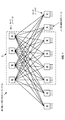
図1は、3段折り返しClosネットワーク10の一例としてのネットワークトポロジーの図である。折り返される入口/出口ステージ(図示した下のステージ)内のノードをエッジノード12といい、中間ステージ(図示した上のステージ)内のノードをルートノード11という。ルートノード11及びエッジノード12を、総称として“ノード”という。各ノード11、12は、自身の入力ポートの全てを自身の出力ポートへと相互接続するスイッチングエレメントである。当該ネットワークは、フレームにより横断されるノードの最大の数が3つ(即ち、エッジからルート、そしてエッジへ)であることから3段(three stage)である。各ルートノード11は、エッジノード12の全てへ接続される。各ルートノード11は、エッジノード12との間の送受信のための複数の入力/出力ポートを含み、各エッジノード12もまた、ルートノード11との間の送受信のための複数の入力/出力ポートを含む。追加的に、各エッジノード12は、ネットワーク10の外部との間でトラフィックを送受信するための、複数のユーザに面する(user-facing)入力/出力ポート13をも含む。
FIG. 1 is a diagram of a network topology as an example of a three-stage folded
図1の例としてのネットワークは、キャパシティが同一であるノードから作られ、8つのエッジノード12を相互接続する4つのルートノード11を含む。別の実施形態では、異なる数のルートノード11及びエッジノード12が含まれてもよい。1つの実施形態において、ネットワーク10は、データセンタ内にある。1つの実施形態において、各ルートノード11は、バックボーンコアブリッジ(BCB)であり、各エッジノード12は、バックボーンエッジブリッジ(BEB)である。
The example network of FIG. 1 includes four
一般には、3段折り返しCLOSネットワークのノンブロッキング特性は、そのルートノード及びエッジノード内のポートの数により左右され得る。例えば、ノンブロッキングなCLOSネットワークにおけるルートノード11の最大数は、ノード別ポート数を2で割った商であり、エッジノード12内のユーザに面するポート13の数は、ルートノードの数とノード別ポート数との積である。
In general, the non-blocking characteristics of a three-stage folded CLOS network can depend on the number of ports in its root node and edge node. For example, the maximum number of
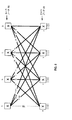
簡明さのために、以下の説明は、基礎となるネットワークとして、破線のボックス15内に示したようなネットワーク10の一部を使用する。理解されることとして、本技術は、様々な数のルートノード及びエッジノードを伴う3段折り返しCLOSネットワークに適用可能である。図2の実施形態に示したように、ルートノード21がラベルA、B、C及びDを付与されており、エッジノード22がラベルw、x、y及びzを付与されている。1つの実施形態において、ルートノード21には、複数のシステムIDセット(例えば、セット1、セット2及びセット3)が割り当てられ、各システムIDセットはルートノード21ごとに区別される(distinct)システムIDを含む。異なるシステムIDセット内の同じルートノード21についてのシステムIDは、同じであっても異なってもよく、例えば、ノードAは3つのシステムIDセットの中でそれぞれシステムID00、00、00を有し、ノードBは3つのシステムIDセットの中でそれぞれ01、02、02を有する。
For simplicity, the following description uses a portion of the
複数のシステムIDセットの使用は、B−VIDについてスパニングツリーのルートノードを選択する際のスプリットタイブレーキングを可能とする。図3を参照しながら詳細に説明されるスプリットタイブレーキングの仕組みによれば、B−VID1、5、9(v1/5/9として示されている)についてのスパニングツリーは、ノードAから発する(rooted)。図2には示していないが、ルートノードBはB−VID2、6、10についてのスパニングツリーのルートであり、ルートノードCはB−VID3、7、11についてのスパニングツリーのルートであり、ルートノードDはB−VID4、8、12についてのスパニングツリーのルートである。よって、ヘッダ内でB−VID1、5又は9を搬送するデータフレームは、エッジノードのいずれからもネットワークへ進入することができ、ルートノードAを通過して、他のエッジノードのいずれかを通じて退出する。ノードAに障害が起き又はラベリングされたリンクのいずれかに障害が起きた場合、影響を受けるトラフィックを、他のルートノードを介する他のリンクへと再分配することができる。障害の無い(fault free)シナリオでは、エッジノードw、x、y及びzの各々が、他のエッジノードへと到達するために、802.1ahの“任意ソース”マルチキャストMAC(*,G)アドレッシングを用いて、データフレームを転送する。なお、顧客レイヤのトラフィックは、それがバックボーンレイヤでどのように転送されたかとは別に、顧客レイヤではブロードキャスト、ユニキャスト又はマルチキャストのいずれかである。
The use of multiple system ID sets allows split tie breaking when selecting the root node of the spanning tree for B-VID. According to the split tie breaking scheme described in detail with reference to FIG. 3, the spanning tree for B-
図3は、スパニングツリールート選択のために使用されるスプリットタイブレーキングの仕組みの一実施形態を示している。スプリットタイブレーキングの仕組みを説明する前に、802.1aqにおいて定義されているタイブレーキングの仕組みを説明することが有益である。802.1aqは、通常、ネットワーク内のトラフィックの各送信元(source)から発する、対称合同的(symmetrically congruent)な最短パスツリーのフルメッシュを生成する。1つのそうしたフルメッシュは、等コストツリー(ECT)セットとして知られている。ECTセットは、通常、B−VIDに関連付けられる。ECTセットの生成の一部としてのパス計算が1つよりも多くの等コストパスからの選択の必要性に至った場合、802.1aqは、ノードIDの辞書順の並び替えを用いて各等コストパスについての一意なパスIDを構築し、パスIDのセットをソートし、最も小さい値を選択する。追加的に、802.1aqは、各ECTセットに関連付けられるセットの値のノードIDとのXOR演算を介して複数のECTセットを生成し、各パスIDにおけるノードIDの辞書順の並び替えを改訂し、パスIDのランク付けを再度行い、最も小さい値を再選択するための手段を仕様化している。 FIG. 3 illustrates one embodiment of a split tie breaking scheme used for spanning tree root selection. Before describing the split tie breaking mechanism, it is useful to describe the tie breaking mechanism defined in 802.1aq. 802.1aq typically produces a full mesh of symmetrically congruent shortest path trees originating from each source of traffic in the network. One such full mesh is known as an equal cost tree (ECT) set. An ECT set is usually associated with a B-VID. When path calculation as part of ECT set generation leads to the need to select from more than one equal cost path, 802.1aq uses each of the node IDs in lexical order to Build a unique path ID for the cost path, sort the set of path IDs, and select the smallest value. In addition, 802.1aq generates multiple ECT sets via XOR operation with the node IDs of the set values associated with each ECT set, and revises the lexical ordering of node IDs in each path ID Then, the path ID is ranked again, and a means for reselecting the smallest value is specified.
ここで説明されるスプリットタイブレーキングの仕組みは、802.1aqに対する改善である。スプリットタイブレーキングの仕組みは、障害の無いシナリオのみならず1つ以上のルートノードに障害が起きた場合における、CLOSネットワーク内のルートノードのセットにわたるトラフィックのより均等な分配を可能とする。スプリットタイブレーキングの仕組みは、次のように、いくつかの設計エレメントを使用する。(1)インスタンス化されるスパニングツリーの数は、ルートノードの数の何らかの倍数となるように選択される。その倍率は、障害の期間中にスプリットタイブレーカの性質を活用する(leverage)ことが望ましい場合、1よりも大きい。(2)ルートノードID(即ち、システムID)は、障害の無いCLOSネットワークにおいて各ルートノードから等しい数のスパニングツリーが発するように設計される。(3)エッジノードIDは、各エッジノードが決してスパニングツリーのルートにならないように設計される。これは、単純に、エッジノードIDの上位ビットに非ゼロの値を使用し、一方でルートノードは上位ビットにゼロを有し、それによりエッジノードIDのセットの最小値がルートノードIDのセットの最大値よりも大きくなるようにすることで、達成され得る。(4)(1)において倍率が1よりも大きい場合、スプリットタイブレーカ値は、障害の起きたルートノードのスパニングツリーのルート(root)が1つよりも多くの他のルートノードにわたって分配されるように設計される。 The split tie breaking mechanism described here is an improvement over 802.1aq. The split tie breaking mechanism allows for a more even distribution of traffic across a set of root nodes in the CLOS network in the event of failure of one or more root nodes as well as failure-free scenarios. The split tie breaking mechanism uses several design elements as follows. (1) The number of spanning trees to be instantiated is selected to be some multiple of the number of root nodes. The magnification is greater than 1 if it is desired to leverage the nature of the split tie breaker during the period of failure. (2) The root node ID (ie, system ID) is designed so that an equal number of spanning trees are emitted from each root node in a CLOS network without a failure. (3) The edge node ID is designed so that each edge node never becomes the root of the spanning tree. This simply uses a non-zero value for the upper bits of the edge node ID, while the root node has a zero for the upper bits, so that the minimum value of the set of edge node IDs is the set of root node IDs. It can be achieved by making it larger than the maximum value of. (4) If the scaling factor is greater than 1 in (1), the split tie breaker value is distributed across the other root nodes where the root of the failed root node is more than one. Designed as such.
図3の実施形態において、システムIDセット23内のシステムIDは、バイナリで示されている。加えて、ネットワーク内の各B−VIDには、例えばマスクセット33に示した例のように、マスク値及びシステムIDセット番号が割当てられている。システムIDセット1に属するB−VID1〜4の各々についてルートノードを決定するために、B−VID1〜4という対応するマスク値を用いて、システムIDセット1について変換が行われる。1つの実施形態において、(所与のマスクを用いた)変換後の最小のシステムIDを有するルートノードが、当該所与のマスクに関連付けられるB−VIDについてのスパニングツリーのルートである。1つの実施形態において、上記変換はXOR演算である。例えば、マスク値0000を伴うB−VID1に関し、マスク値0000及びセット1:0000、0001、0010、0011内のシステムIDについてXORが実行される。(変換されたシステムIDである)XORの結果は、0000、0001、0010、0011である。1つの実施形態において、最小のXOR値をもたらしたルートノードが、対応するB−VIDについてのスパニングツリーのルートとして選択される。よって、B−VID1について、4つの中でXORの結果として0000が最小であるため、ルートノードはノードAである。
In the embodiment of FIG. 3, the system ID in the system ID set 23 is shown in binary. In addition, a mask value and a system ID set number are assigned to each B-VID in the network as in the example shown in the mask set 33, for example. In order to determine the root node for each of the B-
ノードAの障害のケースでは、ノードAを通過するトラフィックは、上で計算されたXORの結果に従って、他のルートノードへとリルートされ得る。例えば、次に小さいXOR値をもたらすルートノードを新たな通過ルートノードとして選択することができ、即ちノードBである。従って、上で計算したXORの結果がB−VID1についてのフェイルオーバ順序を左右する。 In the case of node A failure, traffic passing through node A may be rerouted to other root nodes according to the XOR result calculated above. For example, the root node that yields the next smallest XOR value can be selected as the new passing root node, ie, Node B. Therefore, the XOR result calculated above affects the failover order for B-VID1.
同様に、B−VID5〜8及びB−VID9〜12についてのルート選択を、同じスプリットタイブレーキングの仕組みで実行することができる。B−VID1〜4、B−VID5〜8及びB−VID9〜12は異なるセット内にあるため、各セット内のマスク値及びシステムIDは、他のセットには非依存で構成され得る。1つの実施形態において、管理システムは、各ルートノードをシステムID及びその対応するシステムIDセットと共に構成し得る。管理システムは、ネットワーク内で使用されるB−VIDにマスク値をも割り当て得る。システムセットID番号(例えば、セット1、セット2又はセット3)及び各B−VIDについてのマスク値は、拡張IS−IS(augmented Intermediate System to Intermediate System)hello手続を介してノード間で交換され、又は管理システムにより構成データとして各ノードへロードされ得る。 Similarly, route selection for B-VID 5-8 and B-VID 9-12 can be performed with the same split tie-braking mechanism. Since B-VID1-4, B-VID5-8, and B-VID9-12 are in different sets, the mask value and system ID in each set can be configured independent of the other sets. In one embodiment, the management system may configure each root node with a system ID and its corresponding system ID set. The management system may also assign a mask value to the B-VID used in the network. System set ID numbers (eg, set 1, set 2 or set 3) and mask values for each B-VID are exchanged between nodes via an extended IS-IS (augmented Intermediate System to Intermediate System) hello procedure; Alternatively, it can be loaded into each node as configuration data by the management system.
図4は、3段折り返しCLOSネットワーク内でスパニングツリーのための転送ステートを計算し及びインストールするための方法400の一実施形態を示すフロー図である。1つの実施形態において、拡張IS−ISのhello手続を用いて、ノード間でタイブレーキング情報が交換される(ブロック410)。拡張IS−IS手続を用いて、例えば各B−VIDについて、パス生成アルゴリズム(例えば、スパニングツリー又は等コストツリー)、ルート選択のためのシステムIDセット、及び当該B−VIDについてのマスク値を交換することができる。例えば、ノードに関連付けられるIS−ISスピーカは、以下を広告し得る:B−VID1について、スパニングツリーを使用し、ルート選択のためにシステムIDセット1を使用し、マスク値=00である;B−VID2について、スパニングツリーを使用し、ルート選択のためにシステムIDセット1を使用し、マスク値=01である、など。代替的な実施形態において、タイブレーキング情報は、管理システムにより各ノードへ構成され得る。タイブレーキング情報を取得した後、スパニングツリーのルートノードが、当該タイブレーキング情報に基づいて各B−VIDについて選択される(ブロック420)。図3において説明した通り、所与のB−VIDにより識別されるスパニングツリーについてのルートとして、全てのルートノードの中で最小のシステムIDを有するルートノードが選択されるように、システムIDの変換によってルート選択が行われる。ルート選択の後、各ルートノードについて、エッジノード群までのそのパスが識別される(ブロック430)。1つの実施形態において、ダイクストラのアルゴリズムを用いてネットワーク内の各ノードによりパスが計算される。その代わりに、異なるアルゴリズムが使用されてもよい。
FIG. 4 is a flow diagram illustrating one embodiment of a
ダイクストラのアルゴリズムが使用される実施形態において、計算の結果を用いて、リンク障害の影響を迂回するように転送を修正することができる。計算はネットワーク内の各ノードにより分散的なやり方で行われ、計算の結果は、ノードにより、ネットワーク内のそれらの位置に依存することなく使用され得る。よって、この情報を使用するためにノードは障害の起きたリンクに隣接していなくてよく、なぜならノードはグローバルのトポロジーの知識を取得し、その情報のローカルな個別化を計算するためである。ダイクストラのアルゴリズムは、プロトタイプツリーを生成し、プロトタイプツリーにおいて、1ホップの各パスはルートノードからエッジノードへのパスであり、それらはツリー内で維持され得る。1つより多くのホップを有するパスは、ツリーから除外(pruned)され得る(ブロック440)。例えば、ルートからエッジへ、さらにルートへ、という2ホップのパスが存在するかもしれない。それらパスは、プロトタイプツリーから除外され得る。リンク障害の標識として、3ホップパスが識別される(ブロック450)。3ホップパスの始点はスパニングツリーのルートであり、終点は当該ルートにより直接的に到達可能でないエッジノードである。よって、3ホップパスは、エッジから出発するトラフィックがスパニングツリーのルートを通過できず当該エッジノードへ至るために他のルート(root)を通過しなければならないことを示す。よって、それら3ホップパスをも検討から除外することができ、そのB−VID及び障害の起きたリンクに連結しているエッジノードについて、新たなルートが必要である。3ホップパスによって到達されるノードのリストは、ルートにもはや直接的にアタッチしていないエッジノードのセットとして、将来の計算のために別個に維持される。さらに、4ホップ以上のパスは、ネットワークに病的に(pathologically)障害が起きていることを意味する。なお、上述したパスの除外及び障害検出は、例に過ぎず、最適化が存在してもよい。 In embodiments in which Dijkstra's algorithm is used, the results of the computation can be used to modify the forwarding to bypass the effects of link failure. Calculations are performed in a distributed manner by each node in the network, and the results of the calculations can be used by the nodes independent of their location in the network. Thus, in order to use this information, the node does not have to be adjacent to the failed link, because the node obtains knowledge of the global topology and calculates the local personalization of that information. Dijkstra's algorithm generates a prototype tree, where each one-hop path is a path from a root node to an edge node, which can be maintained in the tree. Paths with more than one hop may be pruned from the tree (block 440). For example, there may be a two-hop path from the root to the edge and further to the root. Those paths can be excluded from the prototype tree. A three-hop path is identified as an indication of link failure (block 450). The starting point of the 3-hop path is the root of the spanning tree, and the end point is an edge node that is not directly reachable by the route. Thus, a three-hop path indicates that traffic departing from an edge cannot pass the spanning tree root and must pass another root in order to reach the edge node. Therefore, these three hop paths can be excluded from the examination, and a new route is required for the edge node connected to the B-VID and the failed link. The list of nodes reached by the 3-hop path is maintained separately for future calculations as a set of edge nodes that are no longer directly attached to the route. Furthermore, a path of 4 hops or more means that the network is pathologically faulty. Note that the above-described path exclusion and failure detection are merely examples, and optimization may exist.
スパニングツリーの生成の後、B−VIDに関連付けられる共通のサービス識別子を有する当該B−VIDについてのエッジノードの各ペアが識別される(ブロック460)。エッジ−エッジノードペアが識別されると、そのそれぞれのフィルタリングデータベース(FDB)が、当該ノードペアの間でユニキャスト及びマルチキャストのデータフレームを転送するための転送エントリ(転送ステートともいう)を含むように構築される(ブロック470)。それらデータフレームは、ネットワークにより提供される対応するサービスを識別するために、ヘッダ内にI−SIDを含むことになる。エッジノードについては、スパニングツリーのルートへのI−SIDマルチキャストアドレスと共に、当該エッジノードのノードとしての(nodal)ユニキャストB−MAC(Backbone MAC)アドレスへのI−SIDマルチキャストアドレスをポインティングすることにより、FDBエントリを生成することができる。ルートノードについては、エッジノードのペアへのマルチキャストエントリに加えて当該ルートノードのノードとしてのユニキャストB−MACへのマルチキャストエントリを相互接続することにより、FDBエントリを生成することができる。ブロック430〜ブロック470の動作は、スパニングツリーの各ルートについて繰り返される。
After generation of the spanning tree, each pair of edge nodes for that B-VID having a common service identifier associated with the B-VID is identified (block 460). When an edge-edge node pair is identified, its respective filtering database (FDB) is constructed to include forwarding entries (also called forwarding states) for forwarding unicast and multicast data frames between the pair of nodes. (Block 470). These data frames will include an I-SID in the header to identify the corresponding service provided by the network. For an edge node, by pointing the I-SID multicast address to the root of the spanning tree and the I-SID multicast address to the (nodal) unicast B-MAC (Backbone MAC) address as the node of the edge node , FDB entries can be generated. For a root node, an FDB entry can be generated by interconnecting a multicast entry for a unicast B-MAC as a node of the root node in addition to a multicast entry for a pair of edge nodes. The operations of
図5は、図2のネットワークの一実施形態を示しており、1つのルートノード(例えば、ノードA)が障害を起こす(“F”により示されている)。図3において説明したスプリットタイブレーキングの仕組みを用いることにより、ノードA上のデータ転送の作業負荷(workload)を、B−VID1、5及び9について2番目に小さいXOR結果(バイナリで0001)を有する他のノードへとシフトすることができる。従って、ノードB、C及びDが、B−VID1、5及び9についてそれぞれスパニングツリーのルートになる。作業負荷のシフトは、エッジノードにより使用されるマルチキャストアドレッシングを変化させない。よって、エッジノードw、x、y及びzは、802.1ahの“任意ソース”マルチキャストMAC(*,G)アドレッシング(簡明さのために(*,G)アドレッシングともいう)を用いて、他のエッジノードへのマルチキャストデータフレームの転送を継続する。
FIG. 5 illustrates one embodiment of the network of FIG. 2, where one root node (eg, node A) fails (indicated by “F”). By using the split tie breaking mechanism described in FIG. 3, the data transfer workload on node A is the second smallest XOR result (binary 0001) for B-VID1, 5 and 9. You can shift to other nodes that you have. Therefore, nodes B, C, and D become the spanning tree roots for B-
図6〜図11は、1つ以上のリンクに障害が起きる、一例としての3段折り返しCLOSネットワークにおけるいくつかのシナリオを示している。図4のブロック450において説明したように、スパニングツリーのルートからエッジノードへのパスを計算するためにダイクストラのアルゴリズムが使用されるスパニングツリー生成の際に、リンク障害が検出され得る。図4のブロック450に示したように、スパニングツリー内の3ホップパスは、リンク障害及び影響を受けるノードを示している。理解されることとして、3段折り返しCLOSネットワークにおいてノード障害又はリンク障害の帰結を検出するために、他の方法が使用されてもよい。
6-11 illustrate several scenarios in an exemplary three-stage folded CLOS network where one or more links fail. As described in
図6は、ノードAとノードWとの間のリンクに障害が発生するシナリオを示している。ノードAについてスパニングツリーが計算されると、ノードWは、3ホップパスによりサービスされるものとして現れる。リンク障害を識別した後、障害の起きたリンクを使用する各B−VIDについてノードwから発する最短パス優先(SPF)ツリーが構築される。IS−ISなどのリンクステートルーティングプロトコルを介して、各ノードは、ネットワーク内のトポロジー情報を学習し、当該情報をSPFツリーを計算するために使用する。1つの実施形態において、各ノードにより、ダイクストラのアルゴリズムを用いてSPFツリーを計算することができる。これらノードは、トポロジー情報に基づいてネットワークの同じビューを構築する。 FIG. 6 shows a scenario in which a failure occurs in the link between the node A and the node W. When the spanning tree is calculated for node A, node W appears to be served by a three-hop path. After identifying the link failure, a shortest path first (SPF) tree emanating from node w is built for each B-VID that uses the failed link. Through a link state routing protocol such as IS-IS, each node learns topology information in the network and uses that information to compute the SPF tree. In one embodiment, each node can compute an SPF tree using Dijkstra's algorithm. These nodes build the same view of the network based on topology information.
1つの実施形態において、SPFツリーの構築は、どのルートノードを通過すべきかを決定するための、前述したスプリットタイブレーキングの仕組みの使用を含む。なお、これらSPFツリーのルートはネットワークのエッジノードであり、ネットワークのルートノードはSPFツリーの通過ノード(transit nodes)になる。SPFツリーが構築された後、エッジノードは、B−VIDについてエッジ−エッジノードペアにより共有される、I−SIDのインターセクション(即ち、共通のI−SID)を識別する。識別されるエッジノードペアに基づいて、各ノードは、後続のデータ転送のために自身のFDBにデータ投入を行う(populate)。 In one embodiment, SPF tree construction includes the use of the split tie breaking mechanism described above to determine which root node to go through. Note that the roots of these SPF trees are edge nodes of the network, and the root nodes of the network are transit nodes of the SPF tree. After the SPF tree is built, the edge node identifies the I-SID intersection (ie, the common I-SID) that is shared by the edge-edge node pair for the B-VID. Based on the identified edge node pair, each node populates its FDB for subsequent data transfer.
図6の例において、B−VID1、5及び9について作られるSPFが、それぞれv1、v5及びv9でラベリングされたリンクとして示されている。ラベルv1/5/9を伴うノードx、y及びzへ接続するリンクは、障害が無く、従って、ノードx、y及びzにより、それらの間でデータを転送するために、(*,G)アドレッシングを用いて継続的に使用されることができる。一方、ノードwと通信するためには、ノードx、y及びzは、v1、v5及びv9でラベリングされたSPFツリーのリンクを使用する必要がある。よって、1つの実施形態において、エッジノードによりハイブリッドマルチキャストアドレッシングが使用される:ノードx、y及びzは、ノードwへマルチキャストデータを転送するために、ユニキャスト又は802.1aqの“ソース固有”マルチキャストMAC(S,G)アドレッシング(簡明さのために(S,G)アドレッシングともいう)を使用し、x、y及びzの間で使用される接続性が拡張され、一方で、ノードwは、ノードx、y及びzへマルチキャストデータを転送するために、802.1ahマルチキャストMAC(*,G)アドレッシングを使用する。これは、ノードwからのマルチキャストは、全てのピアへ到達する必要があり、x、y及びzからのマルチキャストは、それらが互いへとどのようにマルチキャストを行うかとは別に、ノードwへ到達するために特有の扱いを必要とするからである。。
In the example of FIG. 6, the SPFs created for B-
同じ原理が、図7〜図11に示した以下の例の各々に適用され、即ち、エッジノードが3ホップパスによってのみスパニングツリーから到達可能である場合、そのノードからのSPFツリーが計算され、(*,G)アドレッシングを用いてそのノードからマルチキャストデータが転送され、ユニキャスト又は(S,G)アドレッシングを用いてそのノードへマルチキャストデーが転送される。 The same principle applies to each of the following examples shown in FIGS. 7-11: if an edge node is reachable from the spanning tree only by a three-hop path, the SPF tree from that node is calculated ( *, G) Multicast data is transferred from the node using addressing, and multicast data is transferred to the node using unicast or (S, G) addressing.
図7は、ノードwへ接続している2つのリンクに障害が発生する他のシナリオを示している。このシナリオにおいて、(ノードwから発する)B−VID1についてのSPFツリーはもはやノードA及びBを通過しないため、ノードCが通過ノードとして(例えば、タイブレーキングにより)使用される。B−VID5及びB−VID9についてのSPFツリーは、以前としてノードC及びDをそれぞれ通過することができる。v1/5/9に関するアドレシング方式は以前として(*,G)アドレッシングである。しかしながら、ノードwと通信するために、ノードx、y及びzは、v1/5(v1及びv5を表す)並びにv9でラベリングされたSPFツリーのリンクを使用する必要がある。よって、1つの実施形態において、ノードx、y及びzは、ノードwへマルチキャストデータを転送するためにユニキャスト又は(S,G)アドレッシングを使用し、一方で、ノードwは、ノードx、y及びzへマルチキャストデータを転送するために(*,G)アドレッシングを使用する。 FIG. 7 shows another scenario in which a failure occurs in two links connected to the node w. In this scenario, since the SPF tree for B-VID1 (departing from node w) no longer passes through nodes A and B, node C is used as a transit node (eg, by tie breaking). The SPF trees for B-VID5 and B-VID9 can pass through nodes C and D, respectively, as before. The addressing scheme for v1 / 5/9 is (*, G) addressing as before. However, in order to communicate with node w, nodes x, y and z need to use v1 / 5 (representing v1 and v5) and SPF tree links labeled with v9. Thus, in one embodiment, nodes x, y and z use unicast or (S, G) addressing to forward multicast data to node w, while node w is node x, y And (*, G) addressing is used to forward multicast data to z.
図8は、ノードAへ接続している2つのリンクに障害が発生する他のシナリオを示している。このシナリオにおいて、ノードy及びzは、それらの間で依然として、v1/5/9リンクを介し、802.1ahマルチキャストMAC(*,G)アドレッシングを用いて通信することができる。一方、ノードx及びwと通信するために、ノードy及びzは、v1、v5及びv9でラベリングされたSPFツリーのリンクを使用する必要がある。よって、1つの実施形態において、共通のルートへの障害の起きた隣接関係を有する複数のノードが存在することから、ノードy及びzは、ノードx及びwへマルチキャストデータフレームを転送するために(S,G)アドレッシングを使用し、一方で、ノードw及びxは、互いに並びにノードy及びzへマルチキャストを行うために802.1ahマルチキャストMAC(*,G)アドレッシングを使用する。 FIG. 8 shows another scenario in which a failure occurs in two links connected to the node A. In this scenario, nodes y and z can still communicate with them using 802.1ah multicast MAC (*, G) addressing over the v1 / 5/9 link. On the other hand, in order to communicate with nodes x and w, nodes y and z need to use SPF tree links labeled with v1, v5 and v9. Thus, in one embodiment, since there are multiple nodes with failed adjacencies to a common route, nodes y and z can forward multicast data frames to nodes x and w ( S, G) addressing is used, while nodes w and x use 802.1ah multicast MAC (*, G) addressing to multicast to each other and to nodes y and z.
図9は、ノードA及びWの間の第1のリンクに障害が起き、並びにノードB及びxの間の第2のリンクにも障害が起きる他のシナリオを示している。ノードAについてスパニングツリーが計算されると、ノードWは、3ホップパスによりサービスされるものとして現れる。B−VID1についてのSPFツリーはノードwがノードxと通信するための(ノードBとノードxとの間の)有効なパスをもはや有しないため、この障害の起きたパスをパスw−C−xによって置換えることができ、これは1つよりも多くのルートを通過するノードwからのSPFツリーの計算の結果として判定される。ラベルv1/5/9を伴うノードx、y及びzへのリンクは、障害が無く、従って、ノードx、y及びzにより、それらの間で(*,G)アドレッシングを用いてデータを転送するために継続的に使用されることができる。一方、ノードwと通信するために、ノードx、y及びzは、v1、v5及びv9でラベリングされたSPFツリーのリンクを使用する必要がある。よって、1つの実施形態において、ノードx、y及びzは、ノードwへマルチキャストデータを転送するためにユニキャスト又は(S,G)アドレッシングを使用し、一方で、ノードwは、ノードx、y及びzへマルチキャストデータを転送するために(*,G)アドレッシングを使用する。 FIG. 9 illustrates another scenario in which the first link between nodes A and W fails and the second link between nodes B and x also fails. When the spanning tree is calculated for node A, node W appears to be served by a three-hop path. Since the SPF tree for B-VID1 no longer has a valid path (between node B and node x) for node w to communicate with node x, this failed path is denoted as path w-C- can be replaced by x, which is determined as a result of the computation of the SPF tree from node w passing through more than one route. Links to nodes x, y and z with labels v1 / 5/9 are unhindered and therefore transfer data between them using (*, G) addressing by nodes x, y and z Can be used continuously. On the other hand, in order to communicate with the node w, the nodes x, y and z need to use the SPF tree links labeled with v1, v5 and v9. Thus, in one embodiment, nodes x, y and z use unicast or (S, G) addressing to forward multicast data to node w, while node w is node x, y And (*, G) addressing is used to forward multicast data to z.
図10は、ノードwへ接続する4つのリンクのうちの3つに障害が起きる他のシナリオを示している。このシナリオにおいて、ラベルv1/5/9を伴うノードx、y及びzへのリンクは、障害が無く、従って、ノードx、y及びzにより、それらの間で802.1ahマルチキャストMAC(*,G)アドレッシングを用いてデータを転送するために継続的に使用されることができる。一方、ノードwとの通信は、ノードwとノードDとの間を接続する唯一の有効なリンクを介する。よって、(v1/5/9でラベリングされた)B−VID1、5及び9についてのノードwから発する3つのSPFツリーは、全てノードDを通過する。ノードwと通信するために、ノードx、y及びzは、v1/5/9でラベリングされたSPFツリーのリンクを使用する必要がある。よって、1つの実施形態において、ノードx、y及びzは、ノードwへマルチキャストデータを転送するためにユニキャスト又は(S,G)アドレッシングを使用し、一方で、ノードwは、ノードx、y及びzへマルチキャストデータを転送するために(*,G)アドレッシングを使用する。
FIG. 10 shows another scenario in which three of the four links connecting to the node w fail. In this scenario, the links to the nodes x, y and z with the label v1 / 5/9 are unhindered, so that the nodes x, y and z allow the 802.1ah multicast MAC (*, G) between them. ) Can be used continuously to transfer data using addressing. On the other hand, communication with the node w is via the only valid link connecting the node w and the node D. Thus, all three SPF trees originating from node w for B-
図11は、ノードAへ接続する4つのリンクのうちの3つに障害が起きる他のシナリオを示している。このシナリオにおいて、ノードwとの通信は、ノードwへ接続する唯一の有効なリンク(図中のv1/5/9でラベリングされた左端のリンク)を介する。A−zの間のリンクは、ノードzが他のいずれのエッジノードへ到達するためにもこのリンクを使用できないことから、使用されない。よって、ルートノードAは、有効なデータ転送のためにエッジノードのいずれにもサービスできないことから、ネットワークから“事実上”断絶されている。このシナリオは、4つのマルチキャストアドレスを使用する:ノードw、x及びyは、802.1aqマルチキャストMAC(S,G)アドレッシングを使用し、ノードzは、802.1ahマルチキャストMAC(*,G)アドレッシングを使用する。加えて、ノードAから発する1つのスパニングツリー、並びに、ノードw、x及びyからそれぞれ発する3つのスプリットホライズン計算が存在する。 FIG. 11 shows another scenario where three of the four links connecting to node A fail. In this scenario, communication with the node w is via the only valid link connecting to the node w (the leftmost link labeled with v1 / 5/9 in the figure). The link between A-z is not used because node z cannot use this link to reach any other edge node. Thus, root node A is “virtually” disconnected from the network because it cannot service any of the edge nodes for effective data transfer. This scenario uses four multicast addresses: nodes w, x and y use 802.1aq multicast MAC (S, G) addressing and node z uses 802.1ah multicast MAC (*, G) addressing. Is used. In addition, there is one spanning tree originating from node A and three split horizon calculations originating from nodes w, x and y, respectively.
図12は、3段折り返しCLOSネットワークにおいて障害が発生した場合のデータフレーム転送のための方法1200を示すフロー図である。1つの実施形態において、方法1200は、ルートノードから発するスパニングツリーについての転送ステートを、各ノードが計算し及びインストールすることから開始され(ブロック1210)、ここで、スパニングツリーにおけるデータ転送は、ネットワークに障害が無い場合にはマルチキャストパスについて802.1ahのマルチキャストアドレスを利用する。(例えば、図4にて上述したようにダイクストラのアルゴリズムによって)所与のルートノードへの障害を起こした接続を所与のエッジノードが有することが検出された場合(ブロック1220)、当該所与のエッジノードから発するSPFツリーが、上記所与のエッジノードから発し障害の起きた接続を使用するB−VIDのセットの各々について構築される(ブロック1230)。上記所与のエッジノードと他のエッジノードとにより共有される共通のI−SIDが識別され、この情報を使用して、B−VIDのセットに関連付けられるサービスを共通して有するように識別されるエッジノードペアについて、上記所与のエッジノードと他のエッジノードとの間のペアごとの接続性のために、各ノード内のFDBへデータが投入される(ブロック1240)。FDB内にユニキャストステートがインストールされる(ブロック1250)。トラフィックが所与のエッジノードへと向かうのか所与のエッジノードから来るのかに依存して選択されるマルチキャストアドレッシングのハイブリッドを用いて、FDB内にマルチキャストステートもまたインストールされる(ブロック1260)。そして、ノードは、FDBに従って、ユニキャスト及びマルチキャストデータを転送する(ブロック1270)。データは、ハイブリッドマルチキャストアドレッシングに従って転送され、それと共に、上記所与のエッジノードは802.1ahマルチキャストMACアドレッシングを用いてSPFツリーを介して他のエッジノードへデータフレームを転送し、他のエッジノードはユニキャスト又は802.1aQマルチキャストMACアドレッシングを用いてSPFツリーを介して上記所与のエッジノードへデータフレームを転送する。
FIG. 12 is a flow diagram illustrating a
図2〜図12を参照しながら上で説明した方法400及び1200は、さらに最適化されてもよい。図2の例において、B−VID1〜12について12個のスパニングツリーが生成される(3つのスパニングツリーのみが示されている)。実際には4つのルートのみが存在するため、4つのスパニングツリーの計算の結果が再利用されてもよい。同様に、2つのリンクに障害が起きる最初のシナリオ(図7)及び3つのリンクに障害が起きる最初のシナリオ(図10)において、ノードwからの計算が再利用されてもよい。
The
より小規模なネットワークについて、ある程度の事前の計算と、別個のシステムとしての又はノードに統合されるより簡易な内部システム管理機能とのルーティングシステムの置換えと、を計画することも可能であり、例えば、8ポートのスイッチから作られるCLOSネットワークが32個のリンクを有する。全ての単一のリンク及びノードの障害シナリオの疎なテーブルを前もって構築することもでき、当該テーブルは、B−VIDに対し、どのルート及びどのアドレッシングを使用すべきかをマッピングする。例えば、テーブル内には(232のあり得るネットワークステートに対して)約40個のエントリがある。エッジノードについては、正確なルートノードを転送エントリで指し示すことによって、FDBエントリを生成することができる。ルートノードについては、各エッジペアについての対象のI−SIDのインターセクションを判定し、それに応じてルートFDBにデータ投入することにより、FDBエントリを生成することができる。 For smaller networks, it is also possible to plan for some pre-calculation and replacement of the routing system with a simpler internal system management function as a separate system or integrated into a node, for example A CLOS network made up of 8 port switches has 32 links. A sparse table of all single link and node failure scenarios can also be built in advance, which maps which route and which addressing should be used for the B-VID. For example, there are about 40 entries in the table (for 232 possible network states). For edge nodes, an FDB entry can be generated by pointing the exact root node with a forwarding entry. For the root node, an FDB entry can be generated by determining the intersection of the target I-SID for each edge pair and inputting data in the root FDB accordingly.
上の説明は、移される負荷が生き残るノードにわたって可能な限り均等に共有されるように、障害時の負荷を拡散することを扱っている。しかしながら、全ての顧客がノンブロッキングなサービスからブロッキングなサービスを有するように遷移することになるため、均等な負荷の分配が常に望ましいわけではないかもしれない。1つの実施形態において、障害シナリオの下でのノンブロッキング性を保全するために、(スパニングツリーについてのそれぞれのB−VIDにより識別される)VLANのサブセットへプライオリティが付与され得る。プライオリティの与えられたスパニングツリーのセットの外側での障害は、それらセットの内側には拡散されない。それらセットの内側の障害は、それらセットの外側へと拡散される。このようにして、顧客のサブセットに、障害に直接的に影響されない場合にはいつでも、ノンブロッキングな振る舞いを保証することができる。 The above description deals with spreading the fault load so that the transferred load is shared as evenly as possible across the surviving nodes. However, even load distribution may not always be desirable because all customers will transition from non-blocking services to having blocking services. In one embodiment, a priority can be given to a subset of VLANs (identified by their respective B-VIDs for the spanning tree) to preserve non-blocking under failure scenarios. Failures outside the set of prioritized spanning trees are not propagated inside those sets. Obstacles inside the sets are spread outside the sets. In this way, a subset of customers can be guaranteed non-blocking behavior whenever they are not directly affected by the failure.
さらに、その時点の(current)トラフィックパターンの知識もまた活用されてよい。例えば十分に利用されているネットワークのような、データセンタ内では、トラフィックは均等に分散しているものと想定される。アルゴリズムを、利用度の低い(under-utilized)ネットワークを活用するように開発することができる。例えば、利用度の低いツリーは、障害時にシフトされるトラフィックのより大きなシェアを受け取ることができる。従って、ネットワークは、真にノンブロッキングではなく、提供されるその時点の負荷に基づいてノンブロッキングであるだけである。 In addition, knowledge of current traffic patterns may also be exploited. Within a data center, such as a fully utilized network, traffic is assumed to be evenly distributed. Algorithms can be developed to take advantage of under-utilized networks. For example, underutilized trees can receive a larger share of traffic that is shifted in the event of a failure. Thus, the network is not truly non-blocking, only non-blocking based on the current load provided.
さらに、バックアップノード/パスの構成の変更を、ヒットレスに(即ち、データのロスなく)提供することができる。所与のシステムIDセット内の障害時の第2の又は第3の候補としてのノードの位置を、当該システムIDセット内でのそのシステムIDの変更を介して修正することができる。管理システムは、どのようにトラフィックがシフトされるかを修正するために、それらシステムIDを構成し及び調整することができる。その時点の転送パターンが最小のXORタイブレーカ値に基づくものと仮定すると、次の最良のものの序列を、転送パターンに影響を与えることなくサービス中に修正することができる。 In addition, backup node / path configuration changes can be provided hitlessly (ie, without data loss). The location of the node as the second or third candidate at the time of failure in a given system ID set can be modified via a change in that system ID in that system ID set. The management system can configure and adjust these system IDs to modify how traffic is shifted. Assuming that the current transfer pattern is based on the minimum XOR tiebreaker value, the next best order can be modified in service without affecting the transfer pattern.
図13は、本発明の一実施形態を実装するために使用され得る3段折り返しCLOSネットワークエレメントの一例を示している。ネットワークエレメント310は、上述した3段折り返しCLOSネットワーク内の任意のノード(エッジノード又はルートノード)であってよい。 FIG. 13 shows an example of a three-stage folded CLOS network element that can be used to implement an embodiment of the present invention. The network element 310 may be an arbitrary node (edge node or root node) in the above-described three-stage folded CLOS network.
図13に示したように、ネットワークエレメント310は、スイッチングファブリック330、複数のデータカード335、受信(Rx)インタフェース340、送信(Tx)インタフェース350及びI/Oポート355を含むデータプレーンを含む。Rx及びTxインタフェース340及び350は、I/Oポート355を通じて、ネットワーク内のリンクとインタフェースする。ネットワークエレメントがエッジノードである場合、I/Oポート355は、ネットワークの外部との間の通信を提供するための、ユーザに面する複数のポートをも含む。データカード335は、インタフェース340及び350上で受信されるデータについての機能を実行し、スイッチングファブリック330はデータカード及びI/Oカードの間でデータをスイッチングする。 As shown in FIG. 13, the network element 310 includes a data plane that includes a switching fabric 330, a plurality of data cards 335, a receive (Rx) interface 340, a transmit (Tx) interface 350 and an I / O port 355. Rx and Tx interfaces 340 and 350 interface with links in the network through I / O port 355. If the network element is an edge node, the I / O port 355 also includes a plurality of ports facing the user to provide communication between outside the network. Data card 335 performs functions for data received on interfaces 340 and 350, and switching fabric 330 switches data between data cards and I / O cards.
ネットワークエレメント310は、制御プレーンをも含み、制御プレーンは、データトラフィックの経路制御、転送及び処理をハンドリングするように構成される制御ロジックを収容する1つ以上のネットワークプロセッサ315を含む。ネットワークプロセッサ315は、スパニングツリールート選択のためのスプリットタイブレーカを実行し、スパニングツリーについての転送ステートを計算し及びインストールし、リンク障害の発生時にSPFツリーを計算し、並びにデータ転送のためにFDB326にデータ投入を行うようにも構成される。制御ロジック内に、他の処理もまた実装されてよい。 Network element 310 also includes a control plane that includes one or more network processors 315 that contain control logic configured to handle the routing, forwarding and processing of data traffic. The network processor 315 performs a split tie breaker for spanning tree route selection, calculates and installs forwarding state for the spanning tree, calculates SPF tree when a link failure occurs, and FDB 326 for data transfer. It is also configured to input data. Other processing may also be implemented within the control logic.
ネットワークエレメント310は、FDB326及びトポロジーデータベース322を記憶するメモリ320をも含む。トポロジーデータベース322は、ネットワークのリンクステートを含む、ネットワークモデル又は類似のネットワークトポロジーの表現を記憶する。FDB326は、1つ以上の転送テーブル内にネットワークエレメント310の転送ステートを記憶させ、それらはネットワークエレメント310へのインカミングのトラフィックをどこへ転送すべきかを示す。 The network element 310 also includes a memory 320 that stores an FDB 326 and a topology database 322. The topology database 322 stores a representation of a network model or similar network topology, including the link state of the network. The FDB 326 stores the forwarding state of the network element 310 in one or more forwarding tables, which indicate where incoming traffic to the network element 310 should be forwarded.
1つの実施形態において、ネットワークエレメント310は、管理システム380へ連結され得る。1つの実施形態において、管理システム380は、メモリ370へ連結される1つ以上のプロセッサ360を含む。プロセッサ360は、システムID及びネットワークエレメント310の動作を構成するためのロジックを含み、当該動作は、システムIDの更新及びそれによるネットワーク内の作業の分散と、スパニングツリーのサブセットへの、ネットワークのノンブロッキング特性を少なくともそれらスパニングツリーについて維持するようなプライオリティの割り当てと、を含む。1つの実施形態において、管理システム380は、各ノードについて転送テーブルを計算し、そして転送テーブルをノードへダウンロードするという、システム管理機能を実行してもよい。システム管理機能は、(破線で示されているように)オプションであり、代替的な実施形態において、分散型のルーティングシステムは、各ノードが自身の転送テーブルを計算するように、上記計算を実行してもよい。 In one embodiment, network element 310 may be coupled to management system 380. In one embodiment, management system 380 includes one or more processors 360 that are coupled to memory 370. The processor 360 includes logic to configure the operation of the system ID and network element 310, which includes updating the system ID and thereby distributing work within the network and non-blocking the network to a subset of the spanning tree. Assigning priority to maintain characteristics for at least those spanning trees. In one embodiment, management system 380 may perform a system management function that calculates a forwarding table for each node and downloads the forwarding table to the node. System management functions are optional (as shown by the dashed lines), and in an alternative embodiment, the distributed routing system performs the above calculations so that each node calculates its forwarding table. May be.
ここで説明した実施形態の利点の1つは、ネットワーク内に合計でN個のノードのあるネットワークについて、スパニングツリーのルート選択に適合されたスプリットタイブレーカの使用が、ルートの障害時に計算の負荷が大幅に削減されることを意味し、それにより、計算の複雑さは、(生き残るルートの数)×O(NlnN)となる。これは、複雑さがO(N2lnN)である802.1aqに対して、大幅な改善である。ここで説明した実施形態について、計算上の複雑さは、障害の無いシナリオ及び障害シナリオの双方で削減される。 One of the advantages of the embodiment described here is that for a network with a total of N nodes in the network, the use of a split tie breaker adapted for spanning tree route selection is computationally expensive in the event of a route failure. Is greatly reduced, so that the computational complexity is (number of surviving routes) × O (NlnN). This is a significant improvement over 802.1aq where the complexity is O (N 2 lnN). For the embodiment described here, the computational complexity is reduced in both the failure-free scenario and the failure scenario.
リンク障害のシナリオを解決するためのスプリットホライズン型のルーテッドツリーの使用もまた、計算上の複雑さを低減し、それにより、複雑さは、(ルートの数)×O(NlnN)+(障害リンクに隣接するエッジの数)×O(NlnN)となる。対比として、802.1aqについての名目上の複雑さは、O(N2lnN)である。ここで説明した実施形態についてあらためて言うと、計算上の複雑さは、障害の無いシナリオ及び障害シナリオの双方で削減される。 The use of a split horizon routed tree to solve the link failure scenario also reduces the computational complexity, so that the complexity is (number of routes) × O (NlnN) + (failed links The number of adjacent edges) × O (NlnN). In contrast, the nominal complexity for 802.1aq is O (N 2 lnN). To reiterate the embodiments described herein, computational complexity is reduced in both failure-free and failure scenarios.
さらに、スプリットホライズン型のルーテッドツリーの使用は、障害リンクに隣接する他のエッジノード(例えば、図6〜図11の例におけるノードw)への送信を行うエッジノードだけが、それらの通常のスパニングツリー(*,G)と、当該他のエッジノード(例えば、ノードw)へのユニキャストパスと、へバイキャストする必要があることを意味し、一方で、当該他のエッジノード自体(例えば、ノードw)は、(*,G)アドレッシングを使用し続けることができる。 Furthermore, the use of a split horizon type routed tree is such that only edge nodes that transmit to other edge nodes adjacent to the failed link (eg, node w in the examples of FIGS. 6-11) will be able to perform their normal spanning. This means that the tree (*, G) and the unicast path to the other edge node (eg, node w) need to be bicast, while the other edge node itself (eg, Node w) can continue to use (*, G) addressing.
ルート選択のためのノードとしてのタイブレーカ値の使用は、ルートが他の手段で明示的に識別される必要の無いことを意味し、よって構成ミスをすることがより少ない。 The use of a tie breaker value as a node for route selection means that the route does not need to be explicitly identified by other means and is therefore less likely to make a misconfiguration.
上述の機能は、コンピュータ読取可能なメモリに記憶されてネットワークエレメントに関連付けられたコンピュータプラットフォーム上の1つ以上のプロセッサ上で実行される、プログラム命令のセットとして実現されてもよい。しかしながら、ここで説明した全てのロジックを、複数の個別の構成要素、特定用途向け集積回路(ASIC)等の集積回路、フィールドプログラマブルゲートアレイ(FPGA)若しくはマイクロプロセッサ等のプログラマブルロジックデバイスと一緒に使用されるプログラマブルロジック、ステートマシーン、又は、それらのいずれの組み合わせをも含む他のいずれの装置を使用しても具現化することができることは、当業者には明らかであろう。プログラマブルロジックは、読取専用メモリチップ、コンピュータメモリ、ディスク、又は他の記憶媒体等の有形の媒体に、一時的に又は永久的に固定されることができる。また、プログラマブルロジックは、搬送波で具現化されるコンピュータデータ信号内に固定されることもでき、それにより、プログラマブルロジックを、コンピュータバス又は通信ネットワーク等のインターフェイス上で送信することが可能になる。このようなすべての実施形態は、本発明の範囲に含まれることが意図される。 The functions described above may be implemented as a set of program instructions that are stored in a computer readable memory and executed on one or more processors on a computer platform associated with a network element. However, all of the logic described here is used with multiple individual components, integrated circuits such as application specific integrated circuits (ASICs), programmable logic devices such as field programmable gate arrays (FPGAs) or microprocessors. It will be apparent to those skilled in the art that any other device can be implemented using any programmable logic, state machine, or any combination thereof. The programmable logic can be fixed temporarily or permanently in a tangible medium such as a read-only memory chip, computer memory, disk, or other storage medium. The programmable logic can also be fixed in a computer data signal embodied in a carrier wave, which allows the programmable logic to be transmitted over an interface such as a computer bus or communication network. All such embodiments are intended to be within the scope of the present invention.
図4及び図12のフロー図の動作を、図1、図2及び図13の例示的な実施形態を参照しながら説明した。しかしながら、図4及び図12のフロー図に示す動作を、図1、図2及び図13を参照して議論した実施形態以外の本発明の実施形態によっても実行することができること、また、図1、図2及び図13を参照して議論した実施形態が、図4及び図12の図を参照して議論した動作とは異なる動作を実行することができること、が理解されるべきである。図4及び図12の図は、本発明の特定の実施形態によって実行される動作の具体的な順序を示しているが、この順序は例示であること(例えば、代替の実施形態では、動作が異なる順序で行われ、何らかの動作が組み合わされ、何らかの動作が重複してもよいこと、など)が理解されるべきである。 The operations of the flow diagrams of FIGS. 4 and 12 have been described with reference to the exemplary embodiments of FIGS. However, the operations shown in the flow diagrams of FIGS. 4 and 12 can be performed by embodiments of the present invention other than those discussed with reference to FIGS. 1, 2 and 13, and FIG. It should be understood that the embodiments discussed with reference to FIGS. 2 and 13 can perform operations different from those discussed with reference to the diagrams of FIGS. The diagrams of FIGS. 4 and 12 illustrate the specific order of operations performed by a particular embodiment of the invention, but this order is exemplary (e.g., in an alternative embodiment, the operation is It should be understood that some actions are combined, some actions may overlap, etc.).
本発明の多様な実施形態は、ソフトウェア、ファームウェア、及び/又はハードウェアの多様な組み合わせを使用して実装されてよい。従って、図示した技法は、1つ以上の電子デバイス(例えば、エンドステーション、ネットワークエレメント)に記憶されかつそこで実行されるコード及びデータを使用して実装されることができる。そのような電子デバイスは、非一時的なコンピュータ読取可能な記憶媒体(例えば、磁気ディスク、光ディスク、ランダムアクセスメモリ、読出し専用メモリ、フラッシュメモリデバイス、相変化メモリ)及び一時的なコンピュータ読取可能な伝送媒体(例えば、電気的、光学的、音響的、若しくは他の形式の伝搬信号−搬送波、赤外信号、デジタル信号等)、といったコンピュータ読取可能な媒体を使用して、コード及びデータを記憶し並びに(内部で及び/又はネットワークを通じて他の電子デバイスとの間で)通信する。加えて、そのような電子デバイスは、典型的に、1つ以上の記憶デバイス(非一時的な機械読取可能な記憶媒体)、ユーザ入出力デバイス(例えば、キーボード、タッチスクリーン、及び/又はディスプレイ)、並びにネットワーク接続等の、1つ以上の他のコンポーネントに連結された1つ以上のプロセッサのセットを含む。そのプロセッサのセットと他のコンポーネントとの連結は、典型的に、1つ以上のバス及びブリッジ(バスコントローラとも呼ばれる)を通じて行われる。よって、所与の電子デバイスの記憶デバイスは、典型的に、その電子デバイスの1つ以上のプロセッサのセット上での実行のためのコード及び/又はデータを記憶する。 Various embodiments of the present invention may be implemented using various combinations of software, firmware, and / or hardware. Thus, the illustrated techniques can be implemented using code and data stored in and executed by one or more electronic devices (eg, end stations, network elements). Such electronic devices include non-transitory computer readable storage media (eg, magnetic disk, optical disk, random access memory, read only memory, flash memory device, phase change memory) and temporary computer readable transmission. Use computer-readable media such as media (eg, electrical, optical, acoustic, or other forms of propagated signals—carrier waves, infrared signals, digital signals, etc.) to store code and data, and Communicate (internally and / or with other electronic devices through a network). In addition, such electronic devices typically include one or more storage devices (non-transitory machine-readable storage media), user input / output devices (eg, keyboards, touch screens, and / or displays). As well as a set of one or more processors coupled to one or more other components, such as a network connection. The connection between the set of processors and other components is typically done through one or more buses and bridges (also called bus controllers). Thus, the storage device of a given electronic device typically stores code and / or data for execution on the set of one or more processors of that electronic device.
ここで使用されるところでは、ネットワークエレメント(例えば、ルータ、スイッチ、ブリッジ、コントローラ)とは、ネットワーク上の他の機器(例えば、他のネットワークエレメント、エンドステーション)を通信可能に相互に接続する、ハードウェア及びソフトウェアを含む、1つのネットワーキング機器のことである。いくつかのネットワークエレメントは、“マルチサービスのネットワークエレメント”であり、これらは、複数のネットワーキング機能(例えば、ルーティング、ブリッジング、スイッチング、レイヤ2統合、セッションボーダ制御、サービス品質(Quality of Service)、及び/又は加入者管理)についてのサポートを提供し、及び/又は、複数のアプリケーションサービス(例えば、データ、音声、及びビデオ)についてのサポートを提供する。加入者エンドステーション(例えば、サーバ、ワークステーション、ラップトップ、ネットブック、パームトップ、携帯電話、スマートフォン、マルチメディアフォン、VOIP(Voice Over Internet Protocol)フォン、ユーザ機器、端末、携帯型メディアプレーヤ、GPSユニット、ゲームシステム、セットトップボックス)は、インターネットを通じて提供されるコンテンツ/サービス、及び/又は、インターネットにオーバレイされる(例えば、インターネット経由でトンネリングされる)仮想プライベートネットワーク(VPN)上で提供されるコンテンツ/サービスにアクセスする。それらのコンテンツ及び/又はサービスは、典型的に、サービスプロバイダ又はコンテンツプロバイダに属する1つ以上のエンドステーション(例えば、サーバエンドステーション)により、又はピアツーピアサービスに参加するエンドステーションにより提供され、例えば、パブリックウェブページ(例えば、無料コンテンツ、ストアフロント、検索サービス)、プライベートウェブページ(例えば、eメールサービスを提供する、ユーザ名/パスワードによりアクセスされるウェブページ)、及び/又は、VPN上の企業ネットワークを含み得る。典型的に、加入者エンドステーションは、(例えば、アクセスネットワークに(有線又は無線で)連結された顧客構内機器(customer premise equipment)を通じて)エッジネットワークエレメントに連結され、それらエッジネットワークエレメントは、(例えば、1つ以上のコアネットワークエレメントを通じて)他のエッジネットワークエレメントに連結され、それら他のエッジネットワークエレメントは、他のエンドステーション(例えば、サーバエンドステーション)に連結される。
As used herein, a network element (eg, router, switch, bridge, controller) is communicatively connected to other devices (eg, other network elements, end stations) on the network, A networking device, including hardware and software. Some network elements are “multi-service network elements”, which include multiple networking functions (eg, routing, bridging, switching,
本発明をいくつかの実施形態に関して説明してきたが、本発明が上述の実施形態に限定されるものではなく、添付の特許請求の範囲の思想および範囲内で修正及び変形と共に実践されることができることを、当業者は認識するであろう。よって、本説明は、限定ではなく例示と捉えられるべきである。
While the invention has been described in terms of several embodiments, the invention is not limited to the embodiments described above, but can be practiced with modifications and variations within the spirit and scope of the appended claims. Those skilled in the art will recognize that this is possible. Accordingly, the description is to be regarded as illustrative rather than limiting.
Claims (27)
前記ネットワークは、各々がネットワークエレメントを表す複数のノードを含み、前記ノードはルートノードとエッジノードとを含み、各エッジノードは、ユーザに面する入力及び出力ポートのセットを含み、各ルートノードは、エッジノードを相互接続するためのポートのセットを含み、前記方法は、
前記ネットワーク内の各ノードにより、前記ルートノードから発するスパニングツリーについての転送ステートを計算し及びインストールするステップと、前記スパニングツリーにおけるデータ転送は、前記ネットワークに障害が無い場合にはマルチキャストパスについて任意ソースのアドレスを利用することと、
前記エッジノードのうちの所与の1つを、前記ルートノードのうちの所与の1つへの障害を起こした接続を有するものとして識別するステップと、
前記ネットワーク内の各ノード又はシステム管理機能により、前記所与のエッジノードへの接続性のためのプロトタイプとして、前記所与のエッジノードから発する最短パス優先(SPF)ツリーを、前記所与のルートノードから発し前記障害を起こした接続を使用するスパニングツリーについてのB−VID(Backbone Virtual Local Area Network identifiers)のセットの各々について構築するステップと、前記SPFツリーは、前記B−VIDについての前記所与のエッジノードへのユニキャスト及びマルチキャストの接続性のためのプロトタイプとして供されることと、
前記B−VIDの前記セットに関連付けられるサービスを共通して有するように識別される各ノードペアについての、前記所与のエッジノードと他のエッジノードとの間のペアごとの接続性のために、フィルタリングデータベースへデータ投入するステップと、
前記フィルタリングデータベース内にユニキャストステートをインストールするステップと、
トラフィックが前記所与のエッジノードへと向かうのか前記所与のエッジノードから来るのかに依存して選択されるマルチキャストアドレッシングのハイブリッドを用いて、前記フィルタリングデータベース内にマルチキャストステートをインストールするステップと、
前記フィルタリングデータベースに従って、前記ネットワークにおいてユニキャスト及びマルチキャストデータを転送するステップと、
を含む方法。 A method for Ethernet routing with improved efficiency of computational complexity, network operation, multicast addressing, and load redistribution in case of failure in the network in a three-stage folded CLOS network. And
The network includes a plurality of nodes each representing a network element, the nodes including a root node and an edge node, each edge node including a set of input and output ports facing the user, and each root node Including a set of ports for interconnecting edge nodes, the method comprising:
Calculating and installing a forwarding state for a spanning tree originating from the root node by each node in the network, and data forwarding in the spanning tree is an arbitrary source for the multicast path if there is no failure in the network Using the address of
Identifying a given one of the edge nodes as having a failed connection to a given one of the root nodes;
Each node or system management function in the network uses a shortest path first (SPF) tree emanating from the given edge node as a prototype for connectivity to the given edge node. Constructing for each of a set of B-VIDs (Backbone Virtual Local Area Network identifiers) for a spanning tree that originates from a node and uses the failed connection; and the SPF tree includes the location for the B-VID. Serving as a prototype for unicast and multicast connectivity to a given edge node;
For pair-by-pair connectivity between the given edge node and other edge nodes for each node pair identified as having in common the services associated with the set of B-VIDs, Inputting data into the filtering database;
Installing a unicast state in the filtering database;
Installing a multicast state in the filtering database using a hybrid of multicast addressing selected depending on whether traffic is destined for or coming from the given edge node;
Forwarding unicast and multicast data in the network according to the filtering database;
Including methods.
前記所与のエッジノードから前記他のエッジノードへ、同じサービス識別子を有するグループ内の前記エッジノードの全てに到達する、802.1ahマルチキャストMAC(Medium Access Control)アドレッシングを用いて、データフレームの第1のセットを転送するステップと、
前記他のエッジノードの各々から前記所与のエッジノードへ、ユニキャスト又は802.1aqマルチキャストMACアドレッシングを用いて、データフレームの第2のセットを転送するステップと、前記ユニキャスト及び前記802.1aqマルチキャストMACアドレッシングは、前記グループ内の前記エッジノードの全てではなくサブセットへの通信を可能とすることと、
をさらに含む、請求項1の方法。 Said step of transferring a data frame comprises:
Using 802.1ah multicast MAC (Medium Access Control) addressing to reach all of the edge nodes in the group having the same service identifier from the given edge node to the other edge node Transferring a set of ones;
Transferring a second set of data frames from each of the other edge nodes to the given edge node using unicast or 802.1aq multicast MAC addressing; and the unicast and 802.1aq Multicast MAC addressing allows communication to a subset rather than all of the edge nodes in the group;
The method of claim 1 further comprising:
をさらに含む、請求項1の方法。 For each of the spanning trees, when a system ID of the node is converted by a mask value associated with the spanning tree, a root node having a minimum system ID is selected from the nodes in the network. ,
The method of claim 1 further comprising:
をさらに含む、請求項3の方法。 Receiving, by each node, a plurality of system IDs for tie-breaking during spanning tree root selection so that the workload of the failed root node is distributed across other root nodes;
The method of claim 3 further comprising:
前記ネットワーク内の所与のB−VIDについてスパニングツリーを形成するために、ダイクストラのアルゴリズムを用いて、各ルートノードについて、前記エッジノードへのそのパスを計算するステップと、
前記スパニングツリーから、前記エッジノードまでに1つよりも多くのホップを有する前記パスを除外するステップと、
前記スパニングツリー内の3ホップパスを、前記3ホップパスの障害の終点にあたるエッジノードと前記ルートノードとの間のリンク障害を有するものとして識別するステップと、
をさらに含む、請求項1の方法。 Said step of calculating and installing comprises:
Calculating, for each root node, its path to the edge node using Dijkstra's algorithm to form a spanning tree for a given B-VID in the network;
Excluding the path from the spanning tree that has more than one hop to the edge node;
Identifying a three-hop path in the spanning tree as having a link failure between an edge node at the end of the failure of the three-hop path and the root node;
The method of claim 1 further comprising:
識別した前記エッジ−エッジノードペアに基づいて、前記ネットワーク内の各ノードについて前記フィルタリングデータベースを構築するステップと、
をさらに含む、請求項1の方法。 Identifying edge-edge node pairs associated with the same service identifier;
Building the filtering database for each node in the network based on the identified edge-edge node pairs;
The method of claim 1 further comprising:
各エッジノードにより、I−SIDマルチキャストアドレスがスパニングツリーのルートと前記エッジノードのノードとしてのユニキャストアドレスとを指し示すように、前記フィルタリングデータベースにデータ投入するステップと、
各ルートノードにより、前記フィルタリングデータベース内の、識別した前記エッジ−エッジノードペアへのマルチキャストエントリ及び前記ルートノードのノードとしてのユニキャストアドレスへのマルチキャストエントリ、を相互接続するように前記フィルタリングデータベースにデータ投入するステップと、
をさらに含む、請求項6の方法。 The step of building the filtering database comprises:
Populating the filtering database by each edge node so that the I-SID multicast address points to the spanning tree root and the unicast address as the node of the edge node;
Each root node populates the filtering database to interconnect a multicast entry to the identified edge-edge node pair and a multicast entry to a unicast address as the root node node in the filtering database. And steps to
The method of claim 6 further comprising:
前記サブセットの外側での障害を前記サブセットの中へと拡散させることなく、前記サブセットの内側の障害を前記サブセットの外側へと拡散させるステップと、
をさらに含む、請求項1の方法。 Identifying the subset of spanning trees as having priority over other spanning trees in the network;
Spreading obstacles inside the subset out of the subset without spreading obstacles outside the subset into the subset;
The method of claim 1 further comprising:
ユーザに面する入力及び出力ポートの第1のセットと、
複数のルートノードへ連結される入力及び出力ポートの第2のセットと、
フィルタリングデータベースを記憶するメモリと、
前記メモリ、ユーザに面する入力及び出力ポートの前記第1のセット、並びに入力及び出力ポートの前記第2のセット、へ連結されるネットワークプロセッサと、
を備え、
前記ネットワークプロセッサは、
前記ルートノードから発するスパニングツリーについての転送ステートを計算し及びインストールし、
前記所与のエッジノードへの接続性のためのプロトタイプとして、前記所与のエッジノードから発する最短パス優先(SPF)ツリーを、前記所与のルートノードから発し前記障害を起こした接続を使用するスパニングツリーについてのB−VID(Backbone Virtual Local Area Network identifiers)のセットの各々について構築し、前記SPFツリーは、前記B−VIDについての前記所与のエッジノードへのユニキャスト及びマルチキャストの接続性のためのプロトタイプとして供されるものであり、
前記B−VIDのセットに関連付けられるサービスを共通して有するように識別される各ノードペアについての、前記所与のエッジノードと他のエッジノードとの間のペアごとの接続性のために、フィルタリングデータベースへデータ投入し、
前記フィルタリングデータベース内にユニキャストステートをインストールし、
トラフィックが前記所与のエッジノードへと向かうのか前記所与のエッジノードから来るのかに依存して選択されるマルチキャストアドレッシングのハイブリッドを用いて、前記フィルタリングデータベース内にマルチキャストステートをインストールし、
前記フィルタリングデータベースに従って、前記ネットワークにおいてユニキャスト及びマルチキャストデータを転送する、
ように構成される、ネットワークエレメント。 A network element that functions as an edge node of a three-stage folded CLOS network, with improved efficiency in computational complexity, network operation, multicast addressing, and load redistribution in case of failure in the network Using Ethernet routing with the edge node
A first set of input and output ports facing the user;
A second set of input and output ports coupled to a plurality of root nodes;
A memory for storing a filtering database;
A network processor coupled to the memory, the first set of input and output ports facing the user, and the second set of input and output ports;
With
The network processor is
Calculate and install a forwarding state for the spanning tree originating from the root node;
Use as a prototype for connectivity to the given edge node a shortest path first (SPF) tree emanating from the given edge node using the failed connection emanating from the given root node Constructed for each set of B-VIDs (Backbone Virtual Local Area Network identifiers) for Spanning Tree, the SPF tree is unicast and multicast connectivity to the given edge node for the B-VID. Is provided as a prototype for
Filtering for pair-wise connectivity between the given edge node and other edge nodes for each pair of nodes identified to have a common service associated with the set of B-VIDs Populate the database
Install a unicast state in the filtering database;
Install a multicast state in the filtering database using a hybrid of multicast addressing selected depending on whether traffic is destined for or coming from the given edge node;
Forwarding unicast and multicast data in the network according to the filtering database;
A network element configured as follows:
前記所与のエッジノードから前記他のエッジノードへ、同じサービス識別子を有するグループ内の前記エッジノードの全てに到達する、802.1ahマルチキャストMAC(Medium Access Control)アドレッシングを用いて、データフレームの第1のセットを転送し、
前記他のエッジノードの各々から前記所与のエッジノードへ、ユニキャスト又は802.1aqマルチキャストMACアドレッシングを用いて、データフレームの第2のセットを転送する、
ようにさらに構成され、
前記ユニキャスト及び前記802.1aqマルチキャストMACアドレッシングは、前記グループ内の前記エッジノードの全てではなくサブセットへの通信を可能とする、
請求項11のネットワークエレメント。 The network processor is
Using 802.1ah multicast MAC (Medium Access Control) addressing to reach all of the edge nodes in the group having the same service identifier from the given edge node to the other edge node Transfer one set,
Forwarding a second set of data frames from each of the other edge nodes to the given edge node using unicast or 802.1aq multicast MAC addressing;
Further configured as
The unicast and the 802.1aq multicast MAC addressing allow communication to a subset rather than all of the edge nodes in the group;
The network element of claim 11.
ようにさらに構成される、請求項11のネットワークエレメント。 For each of the spanning trees, the network processor selects a root node having a minimum system ID from among the root nodes when the system ID of the root node is converted by a mask value associated with the spanning tree. select,
The network element of claim 11, further configured as follows.
前記ネットワーク内の所与のB−VIDについてスパニングツリーを形成するために、ダイクストラのアルゴリズムを用いて、各ルートノードについて、前記エッジノードへのそのパスを計算し、
前記スパニングツリーから、前記エッジノードまでに1つよりも多くのホップを有する前記パスを除外し、
前記スパニングツリー内の3ホップパスを、前記ルートノードとの間の隣接関係の上でリンク障害を有するノードへ到達するものとして識別する、
ようにさらに構成される、請求項11のネットワークエレメント。 The network processor uses Dijkstra's algorithm to calculate its path to the edge node for each root node to form a spanning tree for a given B-VID in the network;
Excluding the path from the spanning tree that has more than one hop to the edge node;
Identifying a three-hop path in the spanning tree as reaching a node with a link failure on an adjacency relationship with the root node;
The network element of claim 11, further configured as follows.
ユーザに面する入力及び出力ポートのセットを各々が含む複数のエッジノードと、
前記複数のエッジノードを相互接続するためのポートのセットを各々が含む複数のルートノードと、
を含み、
前記ルートノード及びエッジノードの各々は、
フィルタリングデータベースを記憶するメモリと、
前記メモリへ連結されるネットワークプロセッサと、
を備え、
前記ネットワークプロセッサは、
前記ルートノードから発するスパニングツリーについての転送ステートを計算し及びインストールし、
前記所与のエッジノードへの接続性のためのプロトタイプとして、前記所与のエッジノードから発する最短パス優先(SPF)ツリーを、前記所与のルートノードから発し前記障害を起こした接続を使用するスパニングツリーについてのB−VID(Backbone Virtual Local Area Network identifiers)のセットの各々について構築し、前記SPFツリーは、前記B−VIDについての前記所与のエッジノードへのユニキャスト及びマルチキャストの接続性のためのプロトタイプとして供されるものであり、
前記B−VIDのセットに関連付けられるサービスを共通して有するように識別される各ノードペアについての、前記所与のエッジノードと他のエッジノードとの間のペアごとの接続性のために、フィルタリングデータベースへデータ投入し、
前記フィルタリングデータベース内にユニキャストステートをインストールし、
トラフィックが前記所与のエッジノードへと向かうのか前記所与のエッジノードから来るのかに依存して選択されるマルチキャストアドレッシングのハイブリッドを用いて、前記フィルタリングデータベース内にマルチキャストステートをインストールし、
前記フィルタリングデータベースに従って、前記ネットワークにおいてユニキャスト及びマルチキャストデータを転送する、
ように構成される、システム。 A three-stage folded CLOS network system using Ethernet routing with improved efficiency for computational complexity, network operation, multicast addressing, and load redistribution in case of failure in the network The system is
A plurality of edge nodes each including a set of input and output ports facing the user;
A plurality of root nodes each including a set of ports for interconnecting the plurality of edge nodes;
Including
Each of the root node and edge node is
A memory for storing a filtering database;
A network processor coupled to the memory;
With
The network processor is
Calculate and install a forwarding state for the spanning tree originating from the root node;
Use as a prototype for connectivity to the given edge node a shortest path first (SPF) tree emanating from the given edge node using the failed connection emanating from the given root node Constructed for each set of B-VIDs (Backbone Virtual Local Area Network identifiers) for Spanning Tree, the SPF tree is unicast and multicast connectivity to the given edge node for the B-VID. Is provided as a prototype for
Filtering for pair-wise connectivity between the given edge node and other edge nodes for each pair of nodes identified to have a common service associated with the set of B-VIDs Populate the database
Install a unicast state in the filtering database;
Install a multicast state in the filtering database using a hybrid of multicast addressing selected depending on whether traffic is destined for or coming from the given edge node;
Forwarding unicast and multicast data in the network according to the filtering database;
Configured as a system.
をさらに含む、請求項20のシステム。 A management system for constructing the SPF for each B-VID instead of each node in the network;
21. The system of claim 20, further comprising:
前記所与のエッジノードから前記他のエッジノードへ、同じサービス識別子を有するグループ内の前記エッジノードの全てに到達する、802.1ahマルチキャストMAC(Medium Access Control)アドレッシングを用いて、データフレームの第1のセットを転送し、
前記他のエッジノードの各々から前記所与のエッジノードへ、ユニキャスト又は802.1aqマルチキャストMACアドレッシングを用いて、データフレームの第2のセットを転送する、
ようにさらに構成され、
前記ユニキャスト及び前記802.1aqマルチキャストMACアドレッシングは、前記グループ内の前記エッジノードの全てではなくサブセットへの通信を可能とする、
請求項20のシステム。 The network processor is
Using 802.1ah multicast MAC (Medium Access Control) addressing to reach all of the edge nodes in the group having the same service identifier from the given edge node to the other edge node Transfer one set,
Forwarding a second set of data frames from each of the other edge nodes to the given edge node using unicast or 802.1aq multicast MAC addressing;
Further configured as
The unicast and the 802.1aq multicast MAC addressing allow communication to a subset rather than all of the edge nodes in the group;
The system of claim 20.
ようにさらに構成される、請求項20のシステム。 For each of the spanning trees, the network processor selects a root node having a minimum system ID from among the root nodes when the system ID of the root node is converted by a mask value associated with the spanning tree. select,
21. The system of claim 20, further configured as follows.
をさらに含む、請求項23のシステム。 Configure each node with multiple system IDs used for tie-breaking during spanning tree root selection so that the workload of the failed root node is distributed across multiple other root nodes Management system,
24. The system of claim 23, further comprising:
Applications Claiming Priority (3)
| Application Number | Priority Date | Filing Date | Title |
|---|---|---|---|
| US13/458,675 US8848509B2 (en) | 2012-04-27 | 2012-04-27 | Three stage folded Clos optimization for 802.1aq |
| US13/458,675 | 2012-04-27 | ||
| PCT/IB2013/052862 WO2013160786A1 (en) | 2012-04-27 | 2013-04-11 | Three stage folded clos optimization for 802.1aq |
Publications (2)
| Publication Number | Publication Date |
|---|---|
| JP2015518345A JP2015518345A (en) | 2015-06-25 |
| JP6117911B2 true JP6117911B2 (en) | 2017-04-19 |
Family
ID=48577166
Family Applications (1)
| Application Number | Title | Priority Date | Filing Date |
|---|---|---|---|
| JP2015507625A Active JP6117911B2 (en) | 2012-04-27 | 2013-04-11 | Optimization of 3-stage folded CLOS for 802.1AQ |
Country Status (7)
| Country | Link |
|---|---|
| US (1) | US8848509B2 (en) |
| EP (1) | EP2842278B1 (en) |
| JP (1) | JP6117911B2 (en) |
| KR (1) | KR102123035B1 (en) |
| CN (1) | CN104380672B (en) |
| IN (1) | IN2014DN09385A (en) |
| WO (1) | WO2013160786A1 (en) |
Families Citing this family (20)
| Publication number | Priority date | Publication date | Assignee | Title |
|---|---|---|---|---|
| CN102136917B (en) * | 2010-07-14 | 2013-04-17 | 华为技术有限公司 | Ethernet multicast method and device |
| TWI474681B (en) * | 2012-05-11 | 2015-02-21 | Hope Bay Technologies Inc | Connecting method for virtual machine in cloud system |
| US20140086100A1 (en) * | 2012-09-26 | 2014-03-27 | Avaya, Inc. | Multi-Chassis Cluster Synchronization Using Shortest Path Bridging (SPB) Service Instance Identifier (I-SID) Trees |
| US9007892B2 (en) * | 2012-10-26 | 2015-04-14 | Futurewei Technologies, Inc. | Apparatus and method to find partially disjoint routes for dual fiber-cuts |
| US9860081B2 (en) * | 2013-06-18 | 2018-01-02 | Extreme Networks, Inc. | General user network interface (UNI) multi-homing techniques for shortest path bridging (SPB) networks |
| US9565027B2 (en) * | 2013-08-23 | 2017-02-07 | Futurewei Technologies, Inc. | Multi-destination traffic control in multi-level networks |
| US9887914B2 (en) * | 2014-02-04 | 2018-02-06 | Fastly, Inc. | Communication path selection for content delivery |
| US9900217B2 (en) * | 2014-03-26 | 2018-02-20 | Arista Networks, Inc. | Method and system for network topology enforcement |
| US9654401B2 (en) | 2014-03-30 | 2017-05-16 | Juniper Networks, Inc. | Systems and methods for multipath load balancing |
| US9407555B2 (en) * | 2014-03-31 | 2016-08-02 | Juniper Networks, Inc. | Systems and methods for load balancing multicast traffic |
| RU2580100C2 (en) * | 2014-05-16 | 2016-04-10 | Федеральное государственное бюджетное учреждение науки Институт проблем управления им. В.А. Трапезникова Российской академии наук | Generalized two-stage non-blocking clos network |
| US10333725B2 (en) | 2016-03-23 | 2019-06-25 | International Business Machines Corporation | Overlay network with optimized packet flooding |
| WO2018090210A1 (en) * | 2016-11-15 | 2018-05-24 | 华为技术有限公司 | Service packet transmission method, and node apparatus |
| ES2791540T3 (en) * | 2017-02-15 | 2020-11-04 | Maven Wireless Sweden Ab | Distributed Antenna System that provides redundancy |
| US10892980B2 (en) | 2017-02-23 | 2021-01-12 | Maven Wireless Sweden Ab | Routing aggregated carriers in a distributed antenna system |
| CN108833271B (en) * | 2018-05-28 | 2021-02-09 | 全球能源互联网研究院有限公司 | Power grid wide area control service communication path selection method and server |
| US11050679B1 (en) * | 2019-06-28 | 2021-06-29 | Juniper Networks, Inc. | Defining non-forwarding adjacencies in bipartite networks, such as Clos newtorks, having a level 2 backbone and level 1 nodes |
| US11483238B2 (en) * | 2019-10-14 | 2022-10-25 | Cisco Technology, Inc. | Centralized path computation for information-centric networking |
| US11770332B2 (en) * | 2021-02-05 | 2023-09-26 | Extreme Networks, Inc. | MAC-based redistribution policy for multi-area networks |
| CN114401137B (en) * | 2022-01-14 | 2023-09-08 | 中国人民解放军国防科技大学 | Backup network shortest path blocking method and device based on dual algorithm |
Family Cites Families (17)
| Publication number | Priority date | Publication date | Assignee | Title |
|---|---|---|---|---|
| US5684800A (en) | 1995-11-15 | 1997-11-04 | Cabletron Systems, Inc. | Method for establishing restricted broadcast groups in a switched network |
| US6084858A (en) | 1997-01-29 | 2000-07-04 | Cabletron Systems, Inc. | Distribution of communication load over multiple paths based upon link utilization |
| US20050111356A1 (en) * | 2003-11-25 | 2005-05-26 | Whittaker Stewart Mark A. | Connection controller |
| EP1732271B1 (en) * | 2005-06-10 | 2012-02-01 | ParTec Cluster Competence Center GmbH | Data communication system and method with virtual ports |
| US20070002770A1 (en) | 2005-06-30 | 2007-01-04 | Lucent Technologies Inc. | Mechanism to load balance traffic in an ethernet network |
| EP1935145B1 (en) | 2005-10-11 | 2011-12-21 | Telefonaktiebolaget LM Ericsson (publ) | Method of generating spanning trees |
| US7756035B2 (en) | 2006-01-31 | 2010-07-13 | Nortel Networks Limited | Planning routes and allocating identifiers to routes in a managed frame-forwarding network |
| US7911944B2 (en) | 2007-12-26 | 2011-03-22 | Nortel Networks Limited | Tie-breaking in shortest path determination |
| US8576720B2 (en) | 2009-03-12 | 2013-11-05 | Telefonaktiebolaget L M Ericsson (Publ) | Global provisioning of zero-bandwidth traffic engineering label switched paths |
| US8509618B2 (en) * | 2009-05-06 | 2013-08-13 | Ciena Corporation | Photonic routing systems and methods for loop avoidance |
| US8248925B2 (en) | 2009-09-08 | 2012-08-21 | Rockstar Bidco, LP | Method and apparatus for selecting between multiple equal cost paths |
| US8923112B2 (en) * | 2009-10-02 | 2014-12-30 | Telefonaktiebolaget L M Ericsson (Publ) | Technique for controlling data forwarding in computer networks |
| RU2012130857A (en) | 2010-03-26 | 2014-05-10 | РОКСТАР КОНСОРЦИУМ ЮЭс ЛП | METHOD OF RESTORING COMMUNICATION DURING THE MALFUNCTION OF THE COMMUNICATION CHANNEL AND METHOD OF TRANSFER OF TRAFFIC (OPTIONS) |
| US9210071B2 (en) | 2010-08-16 | 2015-12-08 | Telefonaktiebolaget L M Ericsson (Publ) | Automated traffic engineering for fat tree networks |
| US8553584B2 (en) | 2010-09-08 | 2013-10-08 | Telefonaktiebolaget L M Ericsson (Publ) | Automated traffic engineering for 802.1AQ based upon the use of link utilization as feedback into the tie breaking mechanism |
| US9813257B2 (en) * | 2010-09-10 | 2017-11-07 | Extreme Networks, Inc. | Access network dual path connectivity |
| US8949385B2 (en) * | 2011-09-27 | 2015-02-03 | Avaya, Inc. | Method and apparatus for resolving conflicting unicast advertisements in a transport network |
-
2012
- 2012-04-27 US US13/458,675 patent/US8848509B2/en active Active
-
2013
- 2013-04-11 EP EP13727359.5A patent/EP2842278B1/en not_active Not-in-force
- 2013-04-11 KR KR1020147033118A patent/KR102123035B1/en active IP Right Grant
- 2013-04-11 CN CN201380034116.0A patent/CN104380672B/en active Active
- 2013-04-11 JP JP2015507625A patent/JP6117911B2/en active Active
- 2013-04-11 IN IN9385DEN2014 patent/IN2014DN09385A/en unknown
- 2013-04-11 WO PCT/IB2013/052862 patent/WO2013160786A1/en active Application Filing
Also Published As
| Publication number | Publication date |
|---|---|
| KR102123035B1 (en) | 2020-06-15 |
| US20130286817A1 (en) | 2013-10-31 |
| CN104380672B (en) | 2017-12-15 |
| IN2014DN09385A (en) | 2015-07-17 |
| EP2842278B1 (en) | 2016-03-09 |
| EP2842278A1 (en) | 2015-03-04 |
| WO2013160786A1 (en) | 2013-10-31 |
| CN104380672A (en) | 2015-02-25 |
| US8848509B2 (en) | 2014-09-30 |
| KR20150013612A (en) | 2015-02-05 |
| JP2015518345A (en) | 2015-06-25 |
Similar Documents
| Publication | Publication Date | Title |
|---|---|---|
| JP6117911B2 (en) | Optimization of 3-stage folded CLOS for 802.1AQ | |
| EP2614615B1 (en) | Automated traffic engineering for 802.1aq based upon the use of link utilization as feedback into the tie-breaking mechanism | |
| TWI493926B (en) | Automated traffic engineering for fat tree networks | |
| JP6193890B2 (en) | Improved shortest path bridging in multi-area networks | |
| KR102123034B1 (en) | Selecting between equal cost shortest paths in a 802.1aq network using split tiebreakers | |
| US20140112122A1 (en) | System and method for optimizing next-hop table space in a dual-homed network environment | |
| KR20100112144A (en) | Tie-breaking in shortest path determination | |
| JP5961764B2 (en) | Method and apparatus for communication path selection | |
| EP2614618A1 (en) | Automated traffic engineering for multi-protocol label switching (mpls) with link utilization as feedback into the tie-breaking mechanism | |
| CN104378297A (en) | Message forwarding method and device | |
| US20150036508A1 (en) | Method and Apparatus For Gateway Selection In Multilevel SPB Network | |
| JP2016054342A (en) | Communication device, communication method and program |
Legal Events
| Date | Code | Title | Description |
|---|---|---|---|
| A621 | Written request for application examination |
Free format text: JAPANESE INTERMEDIATE CODE: A621 Effective date: 20160311 |
|
| A977 | Report on retrieval |
Free format text: JAPANESE INTERMEDIATE CODE: A971007 Effective date: 20170210 |
|
| TRDD | Decision of grant or rejection written | ||
| A01 | Written decision to grant a patent or to grant a registration (utility model) |
Free format text: JAPANESE INTERMEDIATE CODE: A01 Effective date: 20170221 |
|
| A61 | First payment of annual fees (during grant procedure) |
Free format text: JAPANESE INTERMEDIATE CODE: A61 Effective date: 20170323 |
|
| R150 | Certificate of patent or registration of utility model |
Ref document number: 6117911 Country of ref document: JP Free format text: JAPANESE INTERMEDIATE CODE: R150 |
|
| R250 | Receipt of annual fees |
Free format text: JAPANESE INTERMEDIATE CODE: R250 |
|
| R250 | Receipt of annual fees |
Free format text: JAPANESE INTERMEDIATE CODE: R250 |
|
| R250 | Receipt of annual fees |
Free format text: JAPANESE INTERMEDIATE CODE: R250 |
|
| R250 | Receipt of annual fees |
Free format text: JAPANESE INTERMEDIATE CODE: R250 |
|
| R250 | Receipt of annual fees |
Free format text: JAPANESE INTERMEDIATE CODE: R250 |