JP6117177B2 - Interconnected drive - Google Patents

Interconnected drive Download PDF

Info

Publication number
JP6117177B2
JP6117177B2 JP2014502564A JP2014502564A JP6117177B2 JP 6117177 B2 JP6117177 B2 JP 6117177B2 JP 2014502564 A JP2014502564 A JP 2014502564A JP 2014502564 A JP2014502564 A JP 2014502564A JP 6117177 B2 JP6117177 B2 JP 6117177B2
Authority
JP
Japan
Prior art keywords
sliding member
shaft
locking screwdriver
along
channel
Prior art date
Legal status (The legal status is an assumption and is not a legal conclusion. Google has not performed a legal analysis and makes no representation as to the accuracy of the status listed.)
Active
Application number
JP2014502564A
Other languages
Japanese (ja)
Other versions
JP2014517718A5 (en
JP2014517718A (en
Inventor
マレー・ニコル
ウィルソン・フランク
ヘニング・カイル
ポウエル・ショーン
Current Assignee (The listed assignees may be inaccurate. Google has not performed a legal analysis and makes no representation or warranty as to the accuracy of the list.)
Synthes GmbH
Original Assignee
Synthes GmbH
Priority date (The priority date is an assumption and is not a legal conclusion. Google has not performed a legal analysis and makes no representation as to the accuracy of the date listed.)
Filing date
Publication date
Application filed by Synthes GmbH filed Critical Synthes GmbH
Publication of JP2014517718A publication Critical patent/JP2014517718A/en
Publication of JP2014517718A5 publication Critical patent/JP2014517718A5/ja
Application granted granted Critical
Publication of JP6117177B2 publication Critical patent/JP6117177B2/en
Active legal-status Critical Current
Anticipated expiration legal-status Critical

Links

Images

Classifications

    • AHUMAN NECESSITIES
    • A61MEDICAL OR VETERINARY SCIENCE; HYGIENE
    • A61BDIAGNOSIS; SURGERY; IDENTIFICATION
    • A61B17/00Surgical instruments, devices or methods, e.g. tourniquets
    • A61B17/56Surgical instruments or methods for treatment of bones or joints; Devices specially adapted therefor
    • A61B17/58Surgical instruments or methods for treatment of bones or joints; Devices specially adapted therefor for osteosynthesis, e.g. bone plates, screws, setting implements or the like
    • A61B17/68Internal fixation devices, including fasteners and spinal fixators, even if a part thereof projects from the skin
    • A61B17/84Fasteners therefor or fasteners being internal fixation devices
    • BPERFORMING OPERATIONS; TRANSPORTING
    • B25HAND TOOLS; PORTABLE POWER-DRIVEN TOOLS; MANIPULATORS
    • B25BTOOLS OR BENCH DEVICES NOT OTHERWISE PROVIDED FOR, FOR FASTENING, CONNECTING, DISENGAGING OR HOLDING
    • B25B23/00Details of, or accessories for, spanners, wrenches, screwdrivers
    • B25B23/02Arrangements for handling screws or nuts
    • B25B23/08Arrangements for handling screws or nuts for holding or positioning screw or nut prior to or during its rotation
    • B25B23/10Arrangements for handling screws or nuts for holding or positioning screw or nut prior to or during its rotation using mechanical gripping means
    • B25B23/105Arrangements for handling screws or nuts for holding or positioning screw or nut prior to or during its rotation using mechanical gripping means the gripping device being an integral part of the driving bit
    • B25B23/108Arrangements for handling screws or nuts for holding or positioning screw or nut prior to or during its rotation using mechanical gripping means the gripping device being an integral part of the driving bit the driving bit being a Philips type bit, an Allen type bit or a socket
    • AHUMAN NECESSITIES
    • A61MEDICAL OR VETERINARY SCIENCE; HYGIENE
    • A61BDIAGNOSIS; SURGERY; IDENTIFICATION
    • A61B17/00Surgical instruments, devices or methods, e.g. tourniquets
    • A61B17/56Surgical instruments or methods for treatment of bones or joints; Devices specially adapted therefor
    • A61B17/58Surgical instruments or methods for treatment of bones or joints; Devices specially adapted therefor for osteosynthesis, e.g. bone plates, screws, setting implements or the like
    • A61B17/88Osteosynthesis instruments; Methods or means for implanting or extracting internal or external fixation devices
    • A61B17/8875Screwdrivers, spanners or wrenches
    • A61B17/8877Screwdrivers, spanners or wrenches characterised by the cross-section of the driver bit
    • A61B17/888Screwdrivers, spanners or wrenches characterised by the cross-section of the driver bit the driver bit acting on the central region of the screw head
    • AHUMAN NECESSITIES
    • A61MEDICAL OR VETERINARY SCIENCE; HYGIENE
    • A61BDIAGNOSIS; SURGERY; IDENTIFICATION
    • A61B17/00Surgical instruments, devices or methods, e.g. tourniquets
    • A61B17/56Surgical instruments or methods for treatment of bones or joints; Devices specially adapted therefor
    • A61B17/58Surgical instruments or methods for treatment of bones or joints; Devices specially adapted therefor for osteosynthesis, e.g. bone plates, screws, setting implements or the like
    • A61B17/88Osteosynthesis instruments; Methods or means for implanting or extracting internal or external fixation devices
    • A61B17/8875Screwdrivers, spanners or wrenches
    • A61B17/8886Screwdrivers, spanners or wrenches holding the screw head
    • A61B17/8888Screwdrivers, spanners or wrenches holding the screw head at its central region
    • BPERFORMING OPERATIONS; TRANSPORTING
    • B25HAND TOOLS; PORTABLE POWER-DRIVEN TOOLS; MANIPULATORS
    • B25BTOOLS OR BENCH DEVICES NOT OTHERWISE PROVIDED FOR, FOR FASTENING, CONNECTING, DISENGAGING OR HOLDING
    • B25B15/00Screwdrivers
    • B25B15/001Screwdrivers characterised by material or shape of the tool bit
    • B25B15/004Screwdrivers characterised by material or shape of the tool bit characterised by cross-section
    • B25B15/005Screwdrivers characterised by material or shape of the tool bit characterised by cross-section with cross- or star-shaped cross-section
    • AHUMAN NECESSITIES
    • A61MEDICAL OR VETERINARY SCIENCE; HYGIENE
    • A61BDIAGNOSIS; SURGERY; IDENTIFICATION
    • A61B17/00Surgical instruments, devices or methods, e.g. tourniquets
    • A61B17/56Surgical instruments or methods for treatment of bones or joints; Devices specially adapted therefor
    • A61B17/58Surgical instruments or methods for treatment of bones or joints; Devices specially adapted therefor for osteosynthesis, e.g. bone plates, screws, setting implements or the like
    • A61B17/68Internal fixation devices, including fasteners and spinal fixators, even if a part thereof projects from the skin
    • A61B17/84Fasteners therefor or fasteners being internal fixation devices
    • A61B17/86Pins or screws or threaded wires; nuts therefor
    • A61B17/8605Heads, i.e. proximal ends projecting from bone
    • A61B17/861Heads, i.e. proximal ends projecting from bone specially shaped for gripping driver
    • A61B17/8615Heads, i.e. proximal ends projecting from bone specially shaped for gripping driver at the central region of the screw head

Landscapes

  • Health & Medical Sciences (AREA)
  • Orthopedic Medicine & Surgery (AREA)
  • Surgery (AREA)
  • Life Sciences & Earth Sciences (AREA)
  • Engineering & Computer Science (AREA)
  • Heart & Thoracic Surgery (AREA)
  • Nuclear Medicine, Radiotherapy & Molecular Imaging (AREA)
  • Biomedical Technology (AREA)
  • Medical Informatics (AREA)
  • Molecular Biology (AREA)
  • Animal Behavior & Ethology (AREA)
  • General Health & Medical Sciences (AREA)
  • Public Health (AREA)
  • Veterinary Medicine (AREA)
  • Mechanical Engineering (AREA)
  • Neurology (AREA)
  • Surgical Instruments (AREA)
  • Details Of Spanners, Wrenches, And Screw Drivers And Accessories (AREA)

Description

(関連出願の相互参照)
本特許出願は2011年3月28日に出願された米国特許出願第13/073、294号への優先権を主張し、且つ2011年3月28日出願された国際特許出願第PCT/US2011/030170号への優先権を主張し、それらの開示は、あたかも本明細書に記載されているように、参考として全体が本明細書に援用される。
(Cross-reference of related applications)
This patent application claims priority to US Patent Application No. 13 / 073,294 filed March 28, 2011, and International Patent Application No. PCT / US2011 / filed March 28, 2011. Claims priority to 030170, the disclosures of which are hereby incorporated by reference in their entirety as if set forth herein.

小さい骨アンカー、とりわけ小さい骨ねじが患者内に挿入される又は患者から取り出されるときは、通常、骨ねじが駆動器具の先端から外れて患者の体内で失われる危険性がある。小さい骨ねじを固定すること又はロックすることが可能な駆動器具は、典型的には、駆動器具のシャフトに装着された保持スリーブ若しくは他の構造体を有する。これらの構造体のために、所望の用途に対して大きすぎる直径を駆動器具のシャフトが有する場合があり、外科医が骨ねじ及び/又は目標とする患者の挿入又は取り出し場所を隠蔽する場合がある。   When small bone anchors, especially small bone screws, are inserted into or removed from a patient, there is usually a risk that the bone screws will be disengaged from the tip of the drive device and lost in the patient's body. A drive device capable of securing or locking a small bone screw typically has a retaining sleeve or other structure attached to the shaft of the drive device. Because of these structures, the drive instrument shaft may have a diameter that is too large for the desired application, and the surgeon may conceal the bone screw and / or target patient insertion or removal location. .

一実施形態によると、骨内に骨アンカーを打ち込むように構成されたロッキングねじ回しは、近位端及び、第1の方向に沿って近位端から離間された遠位端を画定するシャフトを含む。遠位端は、骨アンカーの駆動開口部によって受け入れられるように構成される。シャフトは、第1の方向に沿って遠位端から近位端へ延びる第1のガイド部材を画定する。シャフトは遠位端に配置された複数の傾斜部を含み、それぞれの傾斜部は第1の方向に対して角度を付けてオフセットされた傾斜面を画定する。ロッキングねじ回しは、シャフトに沿って複数の傾斜部のそれぞれの上及び解放可能なロックされた位置へ移動するように摺動部材を方向付けるように第1のガイド部材と係合するように構成された第2のガイド部材を含む摺動部材を更に有する。ロッキングねじ回しは、摺動部材及びシャフトの遠位端が駆動開口部に配置され、摺動部材が解放可能にロックされた位置にあるとき、骨アンカーに解放可能にロックされている。ロッキングねじ回しは、更に、解放可能にロックされた位置へシャフトに沿って移動するように摺動部材を付勢する力を付加するように構成された作動装置を有する。   According to one embodiment, a locking screwdriver configured to drive a bone anchor into bone includes a shaft defining a proximal end and a distal end spaced from the proximal end along a first direction. Including. The distal end is configured to be received by the drive opening of the bone anchor. The shaft defines a first guide member extending from the distal end to the proximal end along a first direction. The shaft includes a plurality of ramps disposed at the distal end, each ramp defining an inclined surface that is angled and offset with respect to the first direction. A locking screwdriver is configured to engage the first guide member to direct the sliding member to move along each of the plurality of ramps along the shaft to a releasable locked position. And a sliding member including the second guide member formed. The locking screwdriver is releasably locked to the bone anchor when the sliding member and the distal end of the shaft are located in the drive opening and the sliding member is in a releasably locked position. The locking screwdriver further includes an actuator configured to apply a force that biases the sliding member to move along the shaft to a releasably locked position.

本願の好ましい実施形態の上記要約及び以下の詳細な説明は、添付の図とともに読むことにより、更によく理解されるであろう。相互連結式駆動器具を例示する目的のために、好ましい実施形態を図示する。しかし、本願は図示したとおりの構成及び/又は手段に限定されるものではない。
一実施形態による相互連結式駆動器具の分解斜視図。 組み立てられた構成における図1Aに図示した相互連結式駆動器具の部分立面図。 組み立てられた構成における図1Aに図示した相互連結式駆動器具の斜視図。 代替実施形態により構成された図1Aに図示した相互連結式駆動器具の選択された構成要素の部分立面図。 図1Aに図示した相互連結式駆動器具の作動装置構成要素の部分立面図。 組み立てられた構成における図3Aに図示した作動装置構成要素の部分立面図。 骨アンカーの頭部内に挿入された図1Aに図示した相互連結式駆動器具がロックされていない構成で示されている部分立面図。 骨アンカーの頭部内に挿入された図4Aに図示した相互連結式駆動器具が解放可能にロックされた構成で示されている部分立面図。 代替実施形態により構成された相互連結式駆動器具の分解斜視図。 組み立てられた構成における図5Aに図示した相互連結式駆動器具の部分立面図。 組み立てられた構成における図5Aに図示した相互連結式駆動器具の斜視図。 図5Aに図示した相互連結式駆動器具のシャフトの一部分の部分立面図。 図5Aに図示した相互連結式駆動器具のシャフト及び摺動部材のそれぞれの部分の斜視図。 図5Aに図示した相互連結式駆動器具の作動装置構成要素の部分立面図。 図5Aに図示した相互連結式駆動器具の作動装置の正面図。 骨アンカーの頭部内に挿入され、図5Aに図示した相互連結式駆動器具がロックされていない構成で示されている部分立面図。 骨アンカーの頭部内に挿入され、図9Aに図示した相互連結式駆動器具が解放可能にロックされた構成で示されている部分立面図。 別の代替実施形態により構成された相互連結式駆動器具の分解斜視図。 図10Aに図示した相互連結式駆動器具の、組み立てられた斜視図。 図10Aに図示した相互連結式駆動器具のハンドル構成要素の一部分の斜視図。 図10Aに図示した相互連結式駆動器具のシャフト構成要素の一部分の上面図。 図11Aに図示したシャフトの一部分の側断面図。 図11Aに図示したシャフトの一部分の斜視図。 図11Aに図示したシャフトの一部分の別の斜視図。 図10Aに図示した相互連結式駆動器具の摺動部材構成要素の側面図。 図12Aに図示した摺動部材の底面図。 図12Aに図示した摺動部材の正面図。 図12Aに図示した摺動部材の一部分の側面図。 図12Aに図示した摺動部材の一部分の斜視図。 図10Aに図示した作動装置構成要素並びにシャフト及び摺動部材構成要素の側断面図。 図10Aに図示した相互連結式駆動器具の作動装置構成要素の斜視図。 図14Aに図示した作動装置の側面図。 図14Aに図示した作動装置の正面断面図。 摺動部材が後退した位置内に動作されている、図10Aに図示した組み立てられた相互連結式駆動器具の一部分の斜視図。 摺動部材が部分的に後退した位置内に動作されている、図15Aに図示した相互連結式駆動器具の一部分の側断面図。 摺動部材が解放可能にロックされた位置内に動作されている、図10Aに図示した相互連結式駆動器具の斜視図。 図15A〜Cに図示した相互連結式駆動器具の一部分の側断面図。 相互連結式駆動器具が骨アンカーの駆動開口部内に挿入され、摺動部材が骨アンカーの駆動開口部内に後退した位置内に動作されている、図10Aに図示した相互連結式駆動器具の一部分の部分断面図。 摺動部材が骨アンカーの駆動開口部において部分的に後退した位置内に動作されている、図16Aに図示した相互連結式駆動器具の一部分の側面部分断面図。 摺動部材が骨アンカーの駆動開口部に解放可能にロックされた位置内に動作されている、図16Aに図示した相互連結式駆動器具の一部分の側面部分断面図。
The foregoing summary and the following detailed description of the preferred embodiments of the present application will be better understood when read in conjunction with the appended drawings. For the purpose of illustrating an interconnected drive device, a preferred embodiment is illustrated. However, the present application is not limited to the configuration and / or means as illustrated.
1 is an exploded perspective view of an interconnected drive device according to one embodiment. FIG. FIG. 1B is a partial elevation view of the interconnected drive device illustrated in FIG. 1A in an assembled configuration. 1B is a perspective view of the interconnecting drive illustrated in FIG. 1A in an assembled configuration. FIG. 1B is a partial elevation view of selected components of the interconnected drive illustrated in FIG. 1A configured in accordance with an alternative embodiment. FIG. FIG. 1B is a partial elevation view of an actuator component of the interconnected drive device illustrated in FIG. 1A. FIG. 3B is a partial elevation view of the actuator component illustrated in FIG. 3A in an assembled configuration. 1E is a partial elevation view of the interconnected drive instrument illustrated in FIG. 1A inserted into the bone anchor head in an unlocked configuration. FIG. FIG. 4B is a partial elevational view of the interconnected drive instrument illustrated in FIG. 4A inserted into the bone anchor head in a releasably locked configuration. FIG. 6 is an exploded perspective view of an interconnected drive device configured in accordance with an alternative embodiment. FIG. 5B is a partial elevation view of the interconnecting drive illustrated in FIG. 5A in an assembled configuration. FIG. 5B is a perspective view of the interconnected drive device illustrated in FIG. 5A in an assembled configuration. FIG. 5B is a partial elevational view of a portion of the shaft of the interconnected drive device illustrated in FIG. 5A. FIG. 5B is a perspective view of respective portions of the shaft and the sliding member of the interconnecting drive device illustrated in FIG. 5A. FIG. 5B is a partial elevation view of the actuator component of the interconnected drive device illustrated in FIG. 5A. FIG. 5B is a front view of the actuating device of the interconnected drive device illustrated in FIG. 5A. FIG. 5B is a partial elevational view shown in an unlocked configuration, inserted into the head of the bone anchor and illustrated in FIG. 5A. FIG. 9B is a partial elevational view shown in a releasably locked configuration with the interconnected drive device illustrated in FIG. 9A inserted into the bone anchor head. FIG. 6 is an exploded perspective view of an interconnected drive device constructed in accordance with another alternative embodiment. FIG. 10B is an assembled perspective view of the interconnected drive device illustrated in FIG. 10A. FIG. 10B is a perspective view of a portion of the handle component of the interconnected drive device illustrated in FIG. 10A. FIG. 10B is a top view of a portion of the shaft component of the interconnected drive device illustrated in FIG. 10A. FIG. 11B is a side cross-sectional view of a portion of the shaft illustrated in FIG. 11A. FIG. 11B is a perspective view of a portion of the shaft illustrated in FIG. 11A. FIG. 11B is another perspective view of a portion of the shaft illustrated in FIG. 11A. FIG. 10B is a side view of the sliding member component of the interconnected drive device illustrated in FIG. 10A. FIG. 12B is a bottom view of the sliding member illustrated in FIG. 12A. FIG. 12B is a front view of the sliding member illustrated in FIG. 12A. FIG. 12B is a side view of a portion of the sliding member illustrated in FIG. 12A. FIG. 12B is a perspective view of a portion of the sliding member illustrated in FIG. 12A. FIG. 10B is a cross-sectional side view of the actuator component and the shaft and sliding member component illustrated in FIG. 10A. FIG. 10B is a perspective view of an actuator component of the interconnecting drive illustrated in FIG. 10A. FIG. 14B is a side view of the actuator illustrated in FIG. 14A. FIG. 14B is a front sectional view of the actuator illustrated in FIG. 14A. FIG. 10B is a perspective view of a portion of the assembled interconnected drive illustrated in FIG. 10A with the sliding member operating in a retracted position. FIG. 15B is a cross-sectional side view of a portion of the interconnected drive device illustrated in FIG. 15A with the sliding member being operated in a partially retracted position. FIG. 10B is a perspective view of the interconnecting drive illustrated in FIG. 10A with the sliding member operating in a releasably locked position. FIG. 16 is a cross-sectional side view of a portion of the interconnected drive device illustrated in FIGS. A portion of the interconnected drive instrument illustrated in FIG. 10A, wherein the interconnected drive instrument is inserted into the drive opening of the bone anchor and the sliding member is moved into a retracted position within the drive opening of the bone anchor. FIG. FIG. 16B is a side partial cross-sectional view of a portion of the interconnected drive instrument illustrated in FIG. 16A with the sliding member being operated into a partially retracted position at the drive opening of the bone anchor. FIG. 16B is a side partial cross-sectional view of a portion of the interconnected drive instrument illustrated in FIG. 16A, wherein the sliding member is operated in a releasably locked position in the drive opening of the bone anchor.

便宜上、図中の例示の様々な実施形態における同じ又は同等の要素は同じ参照番号で識別されている。以下の説明では、特定の用語は、単に便宜上使用され、限定ではない。「右」「左」「上」及び「下」という語は、参照する図面における方向を示している。「内向きの」「内向きに」「外向きの」「外向きに」という語は、装置及び/又はその指定された部品の幾何学中心に対して向かう方向及び離れる方向を指す。非限定的であることが意図される用語には、上記の語、それらに派生する語、及び同様の趣旨の語が含まれる。   For convenience, the same or equivalent elements in the various exemplary embodiments illustrated in the figures are identified with the same reference numerals. In the following description, certain terminology is used for convenience only and is not limiting. The terms “right”, “left”, “upper”, and “lower” indicate directions in the referenced drawings. The terms “inward”, “inward”, “outward”, “outward” refer to a direction toward and away from the geometric center of the device and / or its designated part. Terms intended to be non-limiting include the words described above, words derived therefrom, and words of similar intent.

最初に図1A〜Cを参照すると、ロッキングねじ回し又は相互連結式ねじ回しとも呼ばれる場合のある相互連結式駆動器具100は、骨アンカー、具体的には骨ねじなどの締結具に解放可能にロック可能に構成される。例えば、小さい骨ねじなどの小さい骨アンカーが患者に挿入される又は患者から取り出されるときは、例えば骨ねじが駆動器具から外れた場合に患者の体内に骨ねじが失われるのを防ぐために、駆動器具と骨ねじの頭部との間の接合面が固定されることが望ましい。骨アンカー50とロッキングねじ回し100との間の固定された又はロックされた接合面は、ロッキングねじ回し100の拡張可能な遠位端を骨アンカー50の頭部52の中で駆動開口部54内に挿入し、その駆動開口部内でその遠位端を拡張することによって作り出すことができる。ロッキングねじ回し100は、概して、数多くの構成要素、例えばシャフト10、拡張部材20、作動装置30、及びハンドル40を備える。ロッキングねじ回し100の様々な構成要素は、例えば、市販の純粋なチタン、TANのようなチタン合金、ステンレス鋼、フェノールで補強された亜麻布、ケイ素、Radel(登録商標)、超高分子量ポリエチレン(UHMW)などの任意の好適な材料で作製することができる。   Referring initially to FIGS. 1A-C, an interconnecting drive device 100, sometimes referred to as a locking screwdriver or an interconnecting screwdriver, is releasably locked to a fastener, such as a bone anchor, specifically a bone screw. Configured to be possible. For example, when a small bone anchor, such as a small bone screw, is inserted into or removed from a patient, the drive is used to prevent the bone screw from being lost in the patient's body, for example if the bone screw is removed from the drive device. It is desirable that the interface between the instrument and the bone screw head be fixed. The fixed or locked interface between the bone anchor 50 and the locking screwdriver 100 causes the expandable distal end of the locking screwdriver 100 to enter the drive opening 54 within the head 52 of the bone anchor 50. And can be created by expanding its distal end within its drive opening. The locking screwdriver 100 generally includes a number of components such as the shaft 10, the expansion member 20, the actuator 30, and the handle 40. The various components of the locking screwdriver 100 include, for example, commercially pure titanium, titanium alloys such as TAN, stainless steel, linen cloth reinforced with phenol, silicon, Radel®, ultra high molecular weight polyethylene ( It can be made of any suitable material such as UHMW).

シャフト10は長手方向Lにおいて細長く、近位端12aと反対側の遠位端12bとの間に長手方向Lに延在するシャフト本体12を画定し、シャフト本体12は概ね円筒形を有する。シャフト本体12は、可変の断面寸法すなわち直径の1つ以上の部位で構成することができる。例えば、図示した実施形態のシャフト本体12は、第1の直径D1を有するグリップ部位12cと、第2の直径D2を有する中間部位12dと、第3の直径D3を有する第1サブ部位12e’及び直径D3と第4の直径D4との間で長さが減少する先細の直径を有する第2のサブ部位12e”を含む拡張可能な部位12eと、で構成される。図示した実施形態では、第2の直径D2の長さは第1及び第3の直径の長さD1及びD3より大きく、第4の直径D4の長さは第1及び第3の直径D1〜D3の長さより短い。直径D1〜D4の長さは互いに対して別の代替的な割合であってもよいことを理解されたい。更に、シャフト本体12が円筒形の本体に限定されず、シャフト本体12は任意の好適な代替的なシャフト形状に構成されてもよいことを理解されたい。更に、シャフト本体12は図示した可変の直径を有する部位の数に限定されず、シャフト本体12は代わりに、均一又は可変の直径を有する任意の数の部位で構成されてもよいことを理解されたい。   The shaft 10 is elongated in the longitudinal direction L and defines a shaft body 12 extending in the longitudinal direction L between the proximal end 12a and the opposite distal end 12b, the shaft body 12 having a generally cylindrical shape. The shaft body 12 can be configured with one or more sites of variable cross-sectional dimensions or diameters. For example, the shaft body 12 of the illustrated embodiment includes a grip portion 12c having a first diameter D1, an intermediate portion 12d having a second diameter D2, a first sub-portion 12e ′ having a third diameter D3, and And an expandable portion 12e including a second sub-region 12e ″ having a tapered diameter that decreases in length between the diameter D3 and the fourth diameter D4. In the illustrated embodiment, the first portion The length of the diameter D2 of 2 is larger than the lengths D1 and D3 of the first and third diameters, and the length of the fourth diameter D4 is shorter than the lengths of the first and third diameters D1 to D3. It should be understood that the length of ~ D4 may be another alternative ratio relative to each other Furthermore, the shaft body 12 is not limited to a cylindrical body, and the shaft body 12 may be any suitable alternative. May be configured in a typical shaft shape Further, the shaft body 12 is not limited to the number of portions having a variable diameter shown, but the shaft body 12 may instead be composed of any number of portions having a uniform or variable diameter. I hope you understand.

シャフト本体12のグリップ部位12cは、それに配置されたハンドル40のような把持構造体を有するように構成される。図示したハンドル40は、対向する第1端と第2端42a〜bの間及び対向する平面の側面42cの間にそれぞれ長手方向に延在するハンドル本体42を含み、ハンドル本体42は概ね円筒形を有する。ハンドル40が任意の代替的なハンドル本体の形状で構成されてもよいことを理解されたい。長手方向のハンドル穴44は、第1端42aからハンドル本体42の内部に延びる。ハンドル穴44は、その内部にシャフト本体12の近位端12aを受け入れるように構成される。ハンドル40は、ロッキングねじ回し100の動作中にシャフト本体12に連結されたまま留まるように、シャフト本体12の近位端12aに取り付けできる。ハンドル穴44の内面に画定された弧状隆起のような係合構造体がシャフト本体12の近位端12aに画定された相補的なハンドル保持溝13a内に配置されるように、例えば、ハンドル40は、シャフト本体12の近位端12aをハンドル穴44内に挿入することによってシャフト本体12の近位端12aに取り付けることができる。   The grip portion 12c of the shaft body 12 is configured to have a gripping structure such as a handle 40 disposed thereon. The illustrated handle 40 includes a handle body 42 that extends longitudinally between opposing first and second ends 42a-b and between opposing planar side surfaces 42c, the handle body 42 being generally cylindrical. Have It should be understood that the handle 40 may be configured in any alternative handle body shape. A longitudinal handle hole 44 extends from the first end 42 a into the handle body 42. The handle hole 44 is configured to receive the proximal end 12a of the shaft body 12 therein. The handle 40 can be attached to the proximal end 12 a of the shaft body 12 such that it remains connected to the shaft body 12 during operation of the locking screwdriver 100. For example, the handle 40 may be such that an engagement structure, such as an arcuate ridge defined in the inner surface of the handle hole 44, is disposed in a complementary handle retaining groove 13a defined in the proximal end 12a of the shaft body 12. Can be attached to the proximal end 12 a of the shaft body 12 by inserting the proximal end 12 a of the shaft body 12 into the handle hole 44.

シャフト本体12の近位端12aは、キー部位13bを画定することができ、このキー部位13bは、ハンドル穴44の相補的なキー部位に受け入れられるように形成される。ハンドル穴44の相補的なキー部位内でのシャフト本体12のキー部位13bの調整により、シャフト本体12の近位端12a上にハンドル40は正しく方向合わせされる。図示した実施形態のハンドル40、ハンドル保持溝13a、及びキー部位13bが限定的ではないことを理解されたい。例えば、ハンドル40を任意の適切なサイズ及び/又は形の代替的な把持構造体で補うこと及び/又は交換することができる。あるいは代わりに、任意の適切な係合及び/又は保持構造体若しくは方法を用いてハンドル40及び/又は任意の他の把持構造体をシャフト本体12の近位端12aに取り付けてもよいことを更に理解されたい。ディスク11のような1つ以上の分離構造体は、例えばグリップ部位12cが図示したように中間部位12dと隣接するシャフト10上の場所のような1つ以上の場所でシャフト本体12から半径方向に外向きに延びることができる。   The proximal end 12 a of the shaft body 12 can define a key portion 13 b that is formed to be received in a complementary key portion of the handle hole 44. Adjustment of the key portion 13b of the shaft body 12 within the complementary key portion of the handle hole 44 causes the handle 40 to be correctly oriented on the proximal end 12a of the shaft body 12. It should be understood that the handle 40, handle retaining groove 13a, and key portion 13b of the illustrated embodiment are not limiting. For example, the handle 40 can be supplemented and / or replaced with an alternative gripping structure of any suitable size and / or shape. Alternatively, the handle 40 and / or any other gripping structure may alternatively be attached to the proximal end 12a of the shaft body 12 using any suitable engagement and / or retention structure or method. I want you to understand. One or more separating structures, such as the disk 11, may be disposed radially from the shaft body 12 at one or more locations, such as a location on the shaft 10 where the grip portion 12c is adjacent to the intermediate portion 12d as shown. Can extend outward.

シャフト本体12の拡張可能な部位12e及び中間部位12dは、それぞれ、それを通じて長手方向Lに延在する連続穴を有し、この穴は管又はカニューレ部位14を画定し、カニューレ部位14はその内部に拡張部材20を受け入れるように構成される。拡張部材20がカニューレ部位14の内部に完全に配置され得るように、カニューレ部位14の長手方向Lの長さは、対応する拡張部材20の長さよりわずかに長くなるように概ね画定される。拡張部材20がカニューレ部位14内に配置されたときに内部で長手方向Lに移動可能なように、カニューレ部位14は全体を通じて均一の直径D5を有し、直径D5は拡張部材20の直径D6よりわずかに長い(大きい)。   The expandable portion 12e and the intermediate portion 12d of the shaft body 12 each have a continuous hole extending therethrough in the longitudinal direction L, which defines a tube or cannula portion 14 that has an interior thereof. Configured to receive the expansion member 20. The length in the longitudinal direction L of the cannula site 14 is generally defined to be slightly longer than the length of the corresponding dilation member 20 so that the expansion member 20 can be completely disposed within the cannula site 14. The cannula portion 14 has a uniform diameter D5 throughout, such that the diameter D5 is greater than the diameter D6 of the expansion member 20 so that the expansion member 20 can move longitudinally L internally when placed within the cannula portion 14. Slightly long (big).

シャフト本体12の拡張可能な部位12eは、シャフト本体12の遠位端12b内への拡張部材20の長手方向の移動によって拡張されるように構成される。シャフト本体12の遠位端12bが、例えば骨ねじ51のような骨アンカー50の駆動開口部54内に配置されると、以下に詳述するように、拡張可能な部位12eは拡張して、ロッキングねじ回し100と骨ねじ51との間にロックされた接合面を作り出すことができる。シャフト本体12の遠位端12bは相補的な星型駆動ねじ回し開口部を有する骨ねじ内への挿入のために構成された星型駆動ねじ回し構造体とともに構成されるが、遠位端12bが任意の他の形式の骨アンカー駆動開口部との使用のために別の方法で構成されてもよいことを理解されたい。   The expandable portion 12e of the shaft body 12 is configured to be expanded by the longitudinal movement of the expansion member 20 into the distal end 12b of the shaft body 12. When the distal end 12b of the shaft body 12 is disposed within a drive opening 54 of a bone anchor 50, such as a bone screw 51, for example, the expandable portion 12e expands as described in detail below. A locked interface between the locking screwdriver 100 and the bone screw 51 can be created. The distal end 12b of the shaft body 12 is configured with a star drive screwdriver structure configured for insertion into a bone screw having a complementary star drive screwdriver opening, but the distal end 12b. It should be appreciated that may be configured differently for use with any other type of bone anchor drive opening.

直径方向に対向する一対のスロット16がシャフト本体12の拡張可能な部位12eに画定され、これらのスロット16は、遠位端16bと対向する近位端16aとの間でシャフト本体12の遠位端12b内に延び、外面12fからカニューレ部位14内にシャフト本体12を貫通して延びている。スロット16はシャフト本体12の拡張可能な部位12eを対向する弾力的な拡張セグメント18に分割する。以下に詳述するように、拡張セグメント18は、例えば拡張部材20がシャフト本体12の遠位端12b内へと長手方向に移動したときに、長手方向Lに対して実質的に垂直の横断方向Tにおいて互いに対して外向きに屈折可能である。一対の拡張穴17をシャフト本体12に画定することができ、この拡張穴17はシャフト本体12の外面12fからカニューレ部位14内に、シャフト本体12を貫通して延びる。図示した実施形態の拡張穴17はスロット16の近位端16aに画定され、長手方向L及び横断方向Tの両方に対して実質的に垂直の横方向Aにシャフト本体12を貫通して延在する。穴17の直径は、例えば、拡張セグメント18を互いから外向きに離れるように屈折させるために必要とされる力の量を下げることによって、拡張セグメント18の可撓性を増加するように寸法決定してもよい。スロット16が互いに対して直径方向に対向する又は対向しないように、それらがシャフト本体12の円周上の任意の場所に画定され得ることを理解されたい。1つ以上の、例えば複数の、長手方向のスロット16及び/又は対応する拡張穴17をシャフト本体12の拡張可能な部位12eに画定することにより、シャフト本体12の拡張可能な部位12eを対応する複数の拡張セグメント18に分割してもよいことを更に理解されたい。   A pair of diametrically opposed slots 16 are defined in the expandable portion 12e of the shaft body 12, and these slots 16 are distal to the shaft body 12 between the distal end 16b and the opposed proximal end 16a. It extends into the end 12b and extends through the shaft body 12 from the outer surface 12f into the cannula site 14. The slot 16 divides the expandable portion 12e of the shaft body 12 into opposing resilient expansion segments 18. As will be described in more detail below, the expansion segment 18 has a transverse direction substantially perpendicular to the longitudinal direction L, for example when the expansion member 20 is moved longitudinally into the distal end 12b of the shaft body 12. Can be refracted outward at T relative to each other. A pair of expansion holes 17 may be defined in the shaft body 12 that extend through the shaft body 12 from the outer surface 12 f of the shaft body 12 into the cannula site 14. The expansion hole 17 of the illustrated embodiment is defined in the proximal end 16a of the slot 16 and extends through the shaft body 12 in a transverse direction A that is substantially perpendicular to both the longitudinal direction L and the transverse direction T. To do. The diameter of the hole 17 is dimensioned to increase the flexibility of the expansion segment 18, for example, by reducing the amount of force required to refract the expansion segments 18 away from each other. May be. It should be understood that they can be defined anywhere on the circumference of the shaft body 12 such that the slots 16 are diametrically opposed or not opposed to each other. Corresponding to the expandable portion 12e of the shaft body 12 by defining one or more, eg, multiple, longitudinal slots 16 and / or corresponding expansion holes 17 in the expandable portion 12e of the shaft body 12. It should be further understood that a plurality of expansion segments 18 may be divided.

図示した実施形態の拡張部材20は、長手方向にそれぞれ対向する第1の及び第2の端端22a〜bの間に延在する拡張ロッド22のような拡張部材を備え、拡張ロッド22は概ね円筒形を有する。拡張ロッド22は、シャフト本体12のカニューレ部位14内に配置されるように構成される。拡張部材20がカニューレ部位14内に配置されたときに内部で長手方向Lに移動可能なように、拡張ロッドは全体を通じて均一の直径D6を有し、直径D6はカニューレ部位14の直径D5よりわずかに短い長さを有する。拡張ロッド22は、拡張ロッド22の第2端22bに配置された拡張先端部21を備え、この拡張先端部は、拡張ロッド22がシャフト本体12の遠位端12b内へと長手方向に移動したときに互いから外向きに離れるように拡張セグメント18を屈折するように構成される。図示した実施形態では、拡張先端部21は心棒先端部28として構築される。心棒先端部28は、拡張先端部21が、シャフト本体12の遠位端12b内へと、かつしたがってカニューレ部位14内へと長手方向に移動するにつれて、拡張セグメント18を互いから半径方向に外向きに離れるように屈折するように構成された傾斜付きの表面28aを画定する。シャフト本体12のカニューレ部位14は、拡張先端部21がシャフト本体12の遠位端12b内へと移動するにつれて心棒先端部28の傾斜付きの表面28aと係合するように構成された傾斜付きの表面14aであって、その内部に画定された相補的な傾斜付きの表面14aを、例えばシャフト本体12の遠位端12bの近くに有することができる。   The expansion member 20 of the illustrated embodiment includes an expansion member, such as an expansion rod 22 that extends between first and second end ends 22a-b that are each longitudinally opposite, the expansion rod 22 generally It has a cylindrical shape. The expansion rod 22 is configured to be disposed within the cannula portion 14 of the shaft body 12. The expansion rod has a uniform diameter D6 throughout, so that the expansion member 20 is movable longitudinally L internally when disposed within the cannula site 14, which is slightly smaller than the diameter D5 of the cannula site 14. Have a short length. The expansion rod 22 includes an expansion tip 21 disposed at the second end 22 b of the expansion rod 22, which has moved longitudinally into the distal end 12 b of the shaft body 12. Sometimes configured to refract the extension segments 18 away from each other outward. In the illustrated embodiment, the expansion tip 21 is constructed as a mandrel tip 28. Mandrel tip 28 causes expansion segments 18 to radially outward from one another as expansion tip 21 moves longitudinally into distal end 12b of shaft body 12 and thus into cannula site 14. Defining a beveled surface 28a configured to refract away from. The cannula portion 14 of the shaft body 12 is beveled configured to engage the beveled surface 28a of the mandrel tip 28 as the expansion tip 21 moves into the distal end 12b of the shaft body 12. A surface 14a having a complementary beveled surface 14a defined therein may be present, for example, near the distal end 12b of the shaft body 12.

ここで図2を参照すると、代替実施形態において、拡張先端部21は円錐形の表面29aを有する円錐形の先端部29として構成することができる。円錐形先端部29は、拡張先端部21がカニューレ部位14内部からシャフト本体12の遠位端12b内へと長手方向に移動するにつれて、拡張セグメント18を互いから半径方向に外向きに離れるように屈折するように構成される。あるいは、図示したように、カニューレ部位14は、カニューレ部位14がシャフト本体12の遠位端12bの近くに傾斜した表面14bを画定する狭くなった部位を有するように構成されてもよい。具体的には、この狭くなった部位においてカニューレ部位14の直径を、例えば、直径D5から直径D5より短い長さを有する直径D7まで先細にすることができ、そのようにして、拡張先端部21がシャフト本体12の遠位端12b内へと移動するにつれて円錐形先端部29の円錐形の表面29aがカニューレ部位14の狭くなった部位で傾斜した表面14bと係合し、それにより、拡張セグメント18が互いから外向きに半径方向に屈折することを引き起こすことができる。拡張先端部21は拡張ロッド22の第2端22bで一体に画定されてもよく、あるいは代わりに、取り外し可能及び/又は交換可能になるように、拡張ロッド22の第2端22bに連結されてもよいことを理解されたい。   Referring now to FIG. 2, in an alternative embodiment, the extended tip 21 can be configured as a conical tip 29 having a conical surface 29a. The conical tip 29 causes the dilation segments 18 to radially away from each other as the dilation tip 21 moves longitudinally from within the cannula site 14 and into the distal end 12b of the shaft body 12. Configured to refract. Alternatively, as shown, the cannula portion 14 may be configured such that the cannula portion 14 has a narrowed portion that defines a sloped surface 14 b near the distal end 12 b of the shaft body 12. In particular, the diameter of the cannula part 14 can be tapered in this narrowed part, for example from a diameter D5 to a diameter D7 having a length shorter than the diameter D5, and thus the dilating tip 21. As it moves into the distal end 12b of the shaft body 12, the conical surface 29a of the conical tip 29 engages the inclined surface 14b at the narrowed portion of the cannula portion 14, thereby providing an expansion segment. It can cause the 18 to refract radially outward from each other. The expansion tip 21 may be integrally defined at the second end 22b of the expansion rod 22, or alternatively coupled to the second end 22b of the expansion rod 22 so that it can be removed and / or replaced. I hope you understand.

図1A〜Cを参照すると、拡張ロッド22の第1端22aは、作動装置30に連結されるように構成される。図示した実施形態では、拡張ロッド22は、連結ブロック26の形状で連結部材を介して作動装置30に連結される。具体的には、連結ブロック26は、本体24及び、長手方向Lに沿って本体24を貫通して延びる長手方向の穴25を画定する。穴25は、拡張ロッド22の例えば第1端22aで拡張ロッド22を受け入れるように寸法決定される。そのようにして、連結ブロック26は拡張ロッド22を受け入れるように構成される。穴25の内面は、内部に画定された複数のねじ山25aを有し、ねじ山25aは、第1端22aを穴25内にねじ込むことによって連結ブロック26に拡張ロッド22を取り付けることができるように拡張ロッド22の第1端22aの外面に沿って画定された相補的ねじ山23と係合するように形成される。連結ブロック26は、横方向Aに沿ってそれを貫通して延びるピン穴27を更に備え、ピン穴27は、作動装置30に連結ブロック26を連結するピン36を受け入れるように形成される。シャフト本体12は、それを通じて画定されたブロックスロット15を更に備え、ブロックスロット15は横方向Aに沿ってシャフト本体12を貫通して延び、連結ブロック26がブロックスロット15内で長手方向Lに移動可能となるように、その内部に連結ブロック26を受け入れるように寸法決定される。以下に詳述するように、ブロックスロット15は、ロッキングねじ回し100がロックされていない構成と解放可能にロックされている構成との間で動作されるにつれて連結ブロック26及びしたがって拡張ロッド22がブロックスロット15内を長手方向に移動することを可能にするに十分な長手方向の長さを有して画定される。図示した連結ブロック26は概ね矩形を有するが、代替方法として、連結ブロック26は任意の適切な形で形成されてもよいことを理解されたい。更に、拡張部材20、具体的には拡張ロッド22を作動装置30に直接連結することができるように、連結ブロック26を除外してロッキングねじ回し100を代替的に構築してもよいことを理解されたい。   With reference to FIGS. 1A-C, the first end 22 a of the expansion rod 22 is configured to be coupled to the actuator 30. In the illustrated embodiment, the expansion rod 22 is connected to the actuating device 30 via a connecting member in the form of a connecting block 26. Specifically, the connecting block 26 defines a body 24 and a longitudinal hole 25 extending through the body 24 along the longitudinal direction L. The hole 25 is sized to receive the expansion rod 22 at the first end 22a of the expansion rod 22, for example. As such, the connecting block 26 is configured to receive the expansion rod 22. The inner surface of the hole 25 has a plurality of threads 25a defined therein so that the extension rod 22 can be attached to the connecting block 26 by screwing the first end 22a into the hole 25. Is formed to engage a complementary thread 23 defined along the outer surface of the first end 22a of the expansion rod 22. The connecting block 26 further comprises a pin hole 27 extending therethrough along the lateral direction A, the pin hole 27 being formed to receive a pin 36 connecting the connecting block 26 to the actuator 30. The shaft body 12 further comprises a block slot 15 defined therethrough, the block slot 15 extending through the shaft body 12 along the lateral direction A and the connecting block 26 moving in the longitudinal direction L within the block slot 15. It is sized to receive the connecting block 26 therein as possible. As will be described in more detail below, the block slot 15 is configured such that the connecting block 26 and thus the expansion rod 22 block as the locking screwdriver 100 is operated between an unlocked configuration and a releasably locked configuration. Defined with a longitudinal length sufficient to allow longitudinal movement within the slot 15. Although the illustrated connecting block 26 has a generally rectangular shape, it should be understood that as an alternative, the connecting block 26 may be formed in any suitable form. Furthermore, it will be appreciated that the locking screwdriver 100 may alternatively be constructed by omitting the connecting block 26 so that the expansion member 20, in particular the expansion rod 22, can be directly connected to the actuator 30. I want to be.

ここで図1A〜C及び3A〜Bを参照すると、作動装置30が動作されたときに拡張部材20がシャフト本体12のカニューレ部位14内を長手方向に移動するように、拡張部材20は作動装置30に動作可能に連結され、作動装置30はシャフト10に動作可能に連結される。例えば、図示した実施形態では、作動装置30はノブ32として提供される。ノブ32は、対向する第1の及び第2の端34a〜bの間に長手方向Lに延在するノブ本体34を備え、ノブ本体34は概ね円筒形を有する。ノブ本体34は外周面34cを画定する。外周面34cはその表面に画定された隆起部31のような把持構造を有することができ、隆起部31は外面34cから半径方向に外向きに延在する。   Referring now to FIGS. 1A-C and 3A-B, the expansion member 20 is actuated so that the expansion member 20 moves longitudinally within the cannula portion 14 of the shaft body 12 when the actuator 30 is operated. The actuator 30 is operably connected to the shaft 10. For example, in the illustrated embodiment, the actuator 30 is provided as a knob 32. The knob 32 includes a knob body 34 that extends in a longitudinal direction L between opposing first and second ends 34a-b, the knob body 34 having a generally cylindrical shape. The knob body 34 defines an outer peripheral surface 34c. The outer peripheral surface 34c can have a gripping structure such as a raised portion 31 defined on the surface thereof, and the raised portion 31 extends radially outward from the outer surface 34c.

ノブ本体34はそれを通じて画定されたシャフト穴33を備え、シャフト穴33は長手方向Lに沿ってノブ本体34の第1端34aから第2端34bまで延在する。シャフト穴33の内面はその内部に画定された複数のねじ山33aを有し、ねじ山33aはシャフト本体12の外面12f上に画定された相補的ねじ山19と回転可能に係合するように形成される。作動装置30をシャフト本体12に配置することができ、作動装置のねじ山33aがシャフト本体12のねじ山19と係合することができるように、シャフト穴33の直径の長さ(大きさ)は、シャフト本体12の中間部位12dの直径D2の長さ(大きさ)よりわずかに長い(大きい)。図示したシャフト本体12上のねじ山19の場所、及びしたがって作動装置30がシャフト10と連結する場所は、限定的ではないことが意図され、シャフト10と作動装置30との間の接合面は、適宜、シャフト10に沿って任意の場所に位置づけることができることを理解されたい。更に、作動装置30がノブ32に限定されるものではなく、代替方法として、作動装置の動作を拡張部材20の長手方向の移動距離に転換する任意の作動装置が提供されてもよいことを理解されたい。   The knob body 34 includes a shaft hole 33 defined therethrough, and the shaft hole 33 extends along the longitudinal direction L from the first end 34 a to the second end 34 b of the knob body 34. The inner surface of the shaft hole 33 has a plurality of threads 33a defined therein, such that the threads 33a are rotatably engaged with complementary threads 19 defined on the outer surface 12f of the shaft body 12. It is formed. The length (size) of the diameter of the shaft hole 33 so that the actuator 30 can be placed on the shaft body 12 and the thread 33a of the actuator can engage the thread 19 of the shaft body 12. Is slightly longer (larger) than the length (size) of the diameter D2 of the intermediate portion 12d of the shaft body 12. The location of the thread 19 on the illustrated shaft body 12 and thus where the actuator 30 connects to the shaft 10 is intended to be non-limiting and the interface between the shaft 10 and the actuator 30 is It should be understood that it can be located anywhere along the shaft 10 as appropriate. Further, it is understood that the actuator 30 is not limited to the knob 32, and as an alternative, any actuator that converts the operation of the actuator to the longitudinal travel distance of the expansion member 20 may be provided. I want to be.

ノブ本体34は、更に、それを貫通して画定されたピン穴35を備え、ピン穴35は横方向Aに沿って本体34の直径方向の側を貫通して延びる。ピン穴35はピン36を受け入れるように形成され、ピン36は拡張部材20を、具体的には連結ブロック26を、作動装置30に連結するように構成される。図3A〜Bに描かれているように、ノブ本体34は、更に、シャフト穴33内に半径方向に外向きに延在する環状溝37を備え、環状溝37は、ノブ32の回転動作中のピン36の周囲でのノブ本体34の回転を可能にするように構成される。ピン穴35は本体34の対向する側の一方に幅が狭められた部位35aを画定し、幅が狭められた部位35aは環状溝37の底面から本体の外面34cを貫通して延び、幅が狭められた部位35aは、ピン36の直径より短い直径を有するように形成されるので、ピン36がピン穴35内に挿入されたとき、ピン36は幅が狭められた部位35aと隣接し、それによりピン36は環状溝37に置かれ、したがって、ノブ32の回転動作中、ノブ32に対して静止したまま留まる。具体的には、連結ブロック26がシャフト本体12のブロックスロット15に配置され、ピン穴27及び35にピン36を完全に挿入することによってノブ32と動作可能に連結されたとき、ノブ32がシャフト本体12に対して回転されている間、ピン36及び連結ブロック26はノブ32に対して静止したまま留まることができる。   The knob body 34 further includes a pin hole 35 defined therethrough, the pin hole 35 extending along the lateral direction A through the diametrical side of the body 34. The pin hole 35 is formed to receive the pin 36, and the pin 36 is configured to connect the expansion member 20, specifically the connection block 26, to the actuator 30. 3A-B, the knob body 34 further includes an annular groove 37 that extends radially outward into the shaft bore 33, which is in rotation of the knob 32. The knob body 34 is configured to allow rotation around the pin 36. The pin hole 35 defines a narrowed portion 35a on one of the opposing sides of the main body 34, and the narrowed portion 35a extends from the bottom surface of the annular groove 37 through the outer surface 34c of the main body, and has a width of Since the narrowed portion 35a is formed to have a diameter shorter than the diameter of the pin 36, when the pin 36 is inserted into the pin hole 35, the pin 36 is adjacent to the narrowed portion 35a, The pin 36 is thereby placed in the annular groove 37 and therefore remains stationary relative to the knob 32 during the rotational movement of the knob 32. Specifically, when the connecting block 26 is disposed in the block slot 15 of the shaft body 12 and is operatively connected to the knob 32 by fully inserting the pin 36 into the pin holes 27 and 35, the knob 32 is in the shaft. The pin 36 and the connecting block 26 can remain stationary relative to the knob 32 while being rotated relative to the body 12.

ここで図1A〜C及び4A〜Bを参照すると、動作中、例えばある患者の下層の骨の内部への骨ねじ51の挿入及び/又は取り出しのために骨ねじ51のような骨アンカー50をロッキングねじ回し100にロックすることができる。具体的には、シャフト本体12の遠位端12bと骨ねじ51の駆動開口部54との間に固定されたすなわちロックされた接合面が作り出されるように、シャフト本体12の遠位端12bを骨ねじ51の頭部52の中の駆動開口部54内に配置することができる。必要に応じて、ロッキングねじ回し100を動作して、図4Aに描かれている拡張されていない構成又はロックされていない構成にすることができる。ロックされていない構成では、拡張ロッド22の心棒の先端28、具体的にはその傾斜した表面28aは、シャフト本体12の拡張可能な部位12eの拡張セグメント18が拡張されていない弛緩した位置になるように、シャフト本体12の遠位端12bを超えて位置づけられる。作動装置30がシャフト本体12の遠位端12bへ向かう方向にシャフト10のカニューレ部位14内で長手方向に移動するように、ノブ32のねじ山33aがシャフト10の相補的なねじ山19を係合する方向にシャフト10の周囲で作動装置30のノブ32を回転することによって、ロッキングねじ回し100を弛緩した構成に動作することができる。作動装置30が移動するにつれて、拡張部材20(連結ブロック26及び拡張ロッド22を含む)は作動装置30と同時にシャフト本体12の遠位端12bに向かって移動する。このようにして、図4Aに図示されているように、シャフト本体12の遠位端12bを長手方向に超えた位置まで、拡張ロッド22の心棒28を移動させることができる。   Referring now to FIGS. 1A-C and 4A-B, during operation, a bone anchor 50, such as a bone screw 51, may be used for insertion and / or removal of a bone screw 51 into, for example, a patient's underlying bone. The locking screwdriver 100 can be locked. Specifically, the distal end 12b of the shaft body 12 is made to create a fixed or locked interface between the distal end 12b of the shaft body 12 and the drive opening 54 of the bone screw 51. It can be placed in the drive opening 54 in the head 52 of the bone screw 51. If desired, the locking screwdriver 100 can be operated to the unexpanded or unlocked configuration depicted in FIG. 4A. In the unlocked configuration, the mandrel tip 28 of the expansion rod 22, and specifically its inclined surface 28a, is in a relaxed position in which the expansion segment 18 of the expandable portion 12e of the shaft body 12 is not expanded. As such, it is positioned beyond the distal end 12 b of the shaft body 12. The thread 33a of the knob 32 engages the complementary thread 19 of the shaft 10 so that the actuator 30 moves longitudinally within the cannula portion 14 of the shaft 10 in a direction toward the distal end 12b of the shaft body 12. By rotating the knob 32 of the actuator 30 around the shaft 10 in the mating direction, the locking screwdriver 100 can be operated in a relaxed configuration. As the actuator 30 moves, the expansion member 20 (including the connecting block 26 and the expansion rod 22) moves toward the distal end 12b of the shaft body 12 simultaneously with the actuator 30. In this manner, the mandrel 28 of the expansion rod 22 can be moved to a position that extends longitudinally beyond the distal end 12b of the shaft body 12, as illustrated in FIG. 4A.

ロッキングねじ回し100がロックされていない構成で、シャフト本体12の遠位端12bは骨ねじ51の頭部52の中で駆動開口部54内に挿入される。シャフト本体12の遠位端12bが骨ねじ51の駆動開口部54内に挿入された状態で、ロッキングねじ回し100を動作して、骨ねじ51の駆動開口部54内でロックされていない構成から、拡張された、すなわち解放可能にロックされた構成にすることができる。作動装置30がシャフト本体12の遠位端12bから離れる方向にシャフト10のカニューレ部位14内で長手方向に移動するように、ノブ32のねじ山33aをシャフト10の相補的なねじ山19を係合する方向にシャフト10の周囲で作動装置30のノブ32を回転する(すなわち、ロッキングねじ回し100を動作してロックされていない構成にするために使用した回転方向と反対方向にノブ32を回転する)ことによって、ロッキングねじ回し100を解放可能にロックされた構成に動作することができる。作動装置30が移動するにつれて、拡張部材20(連結ブロック26及び拡張ロッド22を含む)は、作動装置30と同時にシャフト本体12の遠位端12bから離れるように移動する。このようにして、図4Bに図示されているように、拡張ロッド22の心棒28はシャフト本体12の遠位端12b内へと移動される。   With the locking screwdriver 100 unlocked, the distal end 12 b of the shaft body 12 is inserted into the drive opening 54 in the head 52 of the bone screw 51. From a configuration in which the locking screwdriver 100 is operated in a state where the distal end 12 b of the shaft body 12 is inserted into the drive opening 54 of the bone screw 51 and is not locked in the drive opening 54 of the bone screw 51. , An expanded or releasably locked configuration. The thread 33a of the knob 32 is engaged with the complementary thread 19 of the shaft 10 so that the actuator 30 moves longitudinally within the cannula portion 14 of the shaft 10 away from the distal end 12b of the shaft body 12. Rotate the knob 32 of the actuator 30 about the shaft 10 in the direction of alignment (ie, rotate the knob 32 in the opposite direction to that used to operate the locking screwdriver 100 to an unlocked configuration). The locking screwdriver 100 can operate in a releasably locked configuration. As the actuator 30 moves, the expansion member 20 (including the connecting block 26 and the expansion rod 22) moves away from the distal end 12b of the shaft body 12 simultaneously with the actuator 30. In this manner, the mandrel 28 of the expansion rod 22 is moved into the distal end 12b of the shaft body 12, as illustrated in FIG. 4B.

拡張ロッド22の心棒の先端28がシャフト本体12の遠位端12b内に移動するにつれて、心棒の先端28の傾斜付き表面28aはシャフト本体12のカニューレ部位14の相互的な傾斜付き表面14aに沿って進み、それによって拡張セグメント18を互いに対して外向きに半径方向に屈折させる。拡張ロッド22の心棒の先端28がシャフト本体12の遠位端12b内に更に移動するにつれて、拡張セグメント18の外面12fは、骨ねじ51の駆動開口部54の内壁54aと係合して、シャフト本体12の拡張セグメント18から外向きに向かう力を駆動開口部54の駆動内壁54aに付与し、かつ駆動開口部54の内壁54aから内向きに向かう力をシャフト本体12の拡張セグメント18に付与し、それによって駆動開口部54は拡張セグメント18の適所にロックされる。次に、骨ねじ51を下層の構造体の中に入れること又は下層の構造体から後退させることができる。骨ねじ51が完全に入れられた又は取り外されたとき、シャフト本体12の遠位端12bを骨ねじ51の駆動開口部54から外すことができる構成すなわちロッキングねじ回し100がロックされていない構成にするように作動装置30を動作することができる。ロッキングねじ回し100をロックされていない構成に動作すると、拡張ロッド22の拡張先端21が骨ねじ51の駆動開口部54の底面54bに隣接するように作動装置30が前進し、それによって、拡張ロッド22からの力を骨ねじ51の頭部52に付与することができ、この力の作用で骨ねじ51がシャフト本体12の遠位端12bから排出されるということを、理解されたい。   As the mandrel tip 28 of the expansion rod 22 moves into the distal end 12b of the shaft body 12, the beveled surface 28a of the mandrel tip 28 is along the mutually beveled surface 14a of the cannula portion 14 of the shaft body 12. And thereby refracting the expanded segments 18 radially outward with respect to each other. As the mandrel tip 28 of the expansion rod 22 moves further into the distal end 12b of the shaft body 12, the outer surface 12f of the expansion segment 18 engages the inner wall 54a of the drive opening 54 of the bone screw 51 and A force directed outward from the expansion segment 18 of the main body 12 is applied to the drive inner wall 54a of the drive opening 54, and a force directed inward from the inner wall 54a of the drive opening 54 is applied to the expansion segment 18 of the shaft main body 12. , Thereby locking the drive opening 54 in place in the expansion segment 18. The bone screw 51 can then be placed in or retracted from the underlying structure. When the bone screw 51 is fully inserted or removed, the distal end 12b of the shaft body 12 can be removed from the drive opening 54 of the bone screw 51, ie, the locking screwdriver 100 is not locked. The actuating device 30 can be operated as such. Actuation of the locking screwdriver 100 to the unlocked configuration advances the actuator 30 so that the expansion tip 21 of the expansion rod 22 is adjacent the bottom surface 54b of the drive opening 54 of the bone screw 51, thereby expanding the expansion rod. It should be understood that a force from 22 can be applied to the head 52 of the bone screw 51 and that the action of the force causes the bone screw 51 to be ejected from the distal end 12b of the shaft body 12.

ここで図5A〜Cを参照すると、代替実施形態によるロッキングねじ回し100が図示されている。以下に詳述するように、ロッキングねじ回し100の遠位端を骨アンカー50の駆動開口部54内に挿入し、ロッキングねじ回し100を動作して摺動部材をロッキングねじ回し100の遠位端内へと長手方向に進めることによって、骨アンカー50と、図示したロッキングねじ回し100の実施形態との間に、固定された、すなわちロックされた接合面を作り出すことができる。ロッキングねじ回し100の図示した実施形態は、概して、シャフト110、摺動部材120、作動装置130、及びハンドル40のような多くの構成要素を備える。   5A-C, a locking screwdriver 100 according to an alternative embodiment is illustrated. As described in detail below, the distal end of the locking screwdriver 100 is inserted into the drive opening 54 of the bone anchor 50 and the locking screwdriver 100 is operated to move the sliding member to the distal end of the locking screwdriver 100. By longitudinally inwardly moving, a fixed or locked interface can be created between the bone anchor 50 and the illustrated locking screwdriver 100 embodiment. The illustrated embodiment of the locking screwdriver 100 generally comprises a number of components such as the shaft 110, the sliding member 120, the actuator 130, and the handle 40.

シャフト110は長手方向Lにおいて細長く、近位端112aと反対側の遠位端112bとの間に長手方向Lに延在するシャフト本体112を画定し、シャフト本体112は概ね円筒形を有する。シャフト本体112は、可変の断面寸法すなわち直径の1つ以上の部位を有するように構成することができる。例えば、図示した実施形態のシャフト本体112は、第1の直径D1’を有するグリップ部位112cと、第2の直径D2’を有する作動装置部位112dと、第3の直径D3’を有する中間部位112eと、直径D3’と第4の直径D4’の間でおおきさが減少する先細の直径を有する先端部位112fとで構築される。図示した実施形態では、第1の直径D1’の大きさは第2の直径の大きさD2’より大きく、D2’の直径は第3の直径D3’より大きく、D3’の直径は第4の直径D4’より大きい。直径の大きさD1’〜D4’は互いに対して別の代替的な割合であってもよいことを理解されたい。更に、シャフト本体112が円筒形の本体に限定されず、シャフト本体112は任意の好適な代替的なシャフト形状に形成されてもよいことを理解されたい。更に、シャフト本体112が図示した可変の直径を有する部位の数に限定されず、シャフト本体112は代わりに、均一又は可変の直径を有する任意の数の部位で構成されてもよいことを理解されたい。   The shaft 110 is elongated in the longitudinal direction L and defines a shaft body 112 extending in the longitudinal direction L between the proximal end 112a and the opposite distal end 112b, the shaft body 112 having a generally cylindrical shape. The shaft body 112 can be configured to have one or more sites with variable cross-sectional dimensions or diameters. For example, the shaft body 112 of the illustrated embodiment includes a grip portion 112c having a first diameter D1 ′, an actuator portion 112d having a second diameter D2 ′, and an intermediate portion 112e having a third diameter D3 ′. And a tip portion 112f having a tapered diameter with a large reduction between the diameter D3 ′ and the fourth diameter D4 ′. In the illustrated embodiment, the first diameter D1 ′ is greater than the second diameter D2 ′, the diameter of D2 ′ is greater than the third diameter D3 ′, and the diameter of D3 ′ is the fourth. Larger than diameter D4 ′. It should be understood that the diameter magnitudes D1'-D4 'may be another alternative ratio relative to each other. Further, it should be understood that the shaft body 112 is not limited to a cylindrical body, and that the shaft body 112 may be formed in any suitable alternative shaft shape. Further, it is understood that the shaft body 112 is not limited to the number of portions having variable diameters shown, and the shaft body 112 may instead be composed of any number of portions having uniform or variable diameters. I want.

シャフト本体112のグリップ部位112cは、その上に配置されたハンドル40のような把持構造体を有するように構成される。任意の適切な係合及び/又は保持構造体若しくは方法を用いてハンドル40及び/又は任意の他の把持構造体をシャフト本体112の近位端112aに取り付けてもよいことを更に理解されたい。シャフト本体112の遠位端112bは、駆動先端部113として構築することができる。摺動部材120の駆動先端部113及び駆動先端部123は、その上に画定されたそれぞれの駆動構造体であってよく、それらは、ロッキングねじ回し100が使用される骨ねじの型式と相補的な駆動構造体である。例えば、図5Cに図示したように、駆動先端部113及び123は、相補的な星型駆動推進開口部を有する骨ねじ内に挿入されるようにその上に画定された星型駆動構造体を有する。代替的手段として駆動先端部113及び/又は123が、対応する代替的なタイプの骨アンカーねじ回し開口部とともに使用するための任意の他の駆動構造体を有する構築であってもよいことを理解されたい。   The grip portion 112c of the shaft body 112 is configured to have a gripping structure such as the handle 40 disposed thereon. It should further be appreciated that the handle 40 and / or any other gripping structure may be attached to the proximal end 112a of the shaft body 112 using any suitable engagement and / or retention structure or method. The distal end 112 b of the shaft body 112 can be constructed as a drive tip 113. The drive tip 113 and drive tip 123 of the sliding member 120 may be respective drive structures defined thereon, which are complementary to the type of bone screw in which the locking screwdriver 100 is used. Drive structure. For example, as illustrated in FIG. 5C, the drive tips 113 and 123 have a star drive structure defined thereon for insertion into a bone screw having a complementary star drive propulsion opening. Have. As an alternative, it is understood that the drive tips 113 and / or 123 may be constructed with any other drive structure for use with a corresponding alternative type of bone anchor screwdriver opening. I want to be.

シャフト本体112の作動装置部位112d、中間部位112e、及び先端部位122fは、それぞれ、それに画定された連続した長手方向のチャネル114を有し、チャネル114は拡張部材120を受け入れるように形成される。チャネル114の長手方向の長さは、概ね、摺動部材120がチャネル114内に完全に配置され得るように、摺動部材120の長手方向の長さよりわずかに長くなるように画定される。チャネル114は、底面114aと、対向する側面114bと、を有する矩形断面の開口チャネルとして形成され、それらの側面114bは、底面114aと、側面114bがシャフト本体112の外面112gと交わる点に沿って画定されるそれぞれの上縁114cとの間で横断方向Tに垂直に延在する。チャネルは、直径D3’の長さ(大きさ)より短い幅W1を横方向Aに有する。チャネル114の断面形状は、摺動部材120がチャネル114内に配置されたときに長手方向Lに移動可能となるように構成される。チャネル114が摺動部材120の概ね矩形の断面とぴったり一致するように概ね矩形の断面を有するように画定されること、及び、例えば代替実施形態にしたがって構築された摺動部材120とぴったり一致するように、他の適切なチャネル形状が代替方法として画定されてもよいことを理解されたい。チャネル114の底面114aは、シャフト本体112の遠位端112bと、傾斜面115から底面114aへの移行部との間に画定される傾斜面115を有し、傾斜面115は、摺動部材120がシャフト本体112の遠位端112b内へと長手方向に移動したときに傾斜面115に沿って摺動部材120が進むように構成される。傾斜面115が図示した実施形態の一直線の表面に限定されないことを理解されたい。例えば、傾斜面115は、遠位端112bと底面114aへの移行部との間で曲線であってもよく、又は代替方法として、任意の他の表面形状を使用して画定されてもよい。   Actuator portion 112d, intermediate portion 112e, and tip portion 122f of shaft body 112 each have a continuous longitudinal channel 114 defined therein, and channel 114 is formed to receive expansion member 120. The longitudinal length of the channel 114 is generally defined to be slightly longer than the longitudinal length of the sliding member 120 so that the sliding member 120 can be fully disposed within the channel 114. The channel 114 is formed as an open channel having a rectangular cross section having a bottom surface 114a and opposing side surfaces 114b, and the side surfaces 114b extend along the point where the bottom surface 114a and the side surface 114b intersect the outer surface 112g of the shaft body 112. It extends perpendicular to the transverse direction T between each upper edge 114c defined. The channel has a width W1 in the lateral direction A that is shorter than the length (size) of the diameter D3 '. The cross-sectional shape of the channel 114 is configured to be movable in the longitudinal direction L when the sliding member 120 is disposed in the channel 114. The channel 114 is defined to have a generally rectangular cross-section so as to closely match the generally rectangular cross-section of the sliding member 120, and closely matches the sliding member 120 constructed, for example, according to alternative embodiments. As such, it should be understood that other suitable channel shapes may alternatively be defined. The bottom surface 114 a of the channel 114 has an inclined surface 115 defined between the distal end 112 b of the shaft body 112 and the transition from the inclined surface 115 to the bottom surface 114 a, and the inclined surface 115 is the sliding member 120. Is configured to advance the sliding member 120 along the inclined surface 115 when moved longitudinally into the distal end 112b of the shaft body 112. It should be understood that the inclined surface 115 is not limited to a straight surface in the illustrated embodiment. For example, the ramp 115 may be curved between the distal end 112b and the transition to the bottom surface 114a, or alternatively may be defined using any other surface shape.

このシャフト本体112は保持部材116を更に備え、保持部材116はチャネル114内に摺動部材120を保持するように構成される。図6に描かれているように、図示した実施形態の保持部材116は、チャネル114の対向する側面114bから内向きに延在する一対の対向する弧形又は弧状突出部117として画定される。突出部117は端117aまで内向きに延びる。突出部117の端117aは、チャネル114の幅W1より短い幅W2を有する隙間によって分離されている。保持部材116は突出部117に限定されず、1つ以上の保持部材116が任意の適切な構造体及び/又は形状を用いて代替的に画定され得ることを理解されたい。   The shaft body 112 further includes a retaining member 116 that is configured to retain the sliding member 120 within the channel 114. As depicted in FIG. 6, the retention member 116 of the illustrated embodiment is defined as a pair of opposing arcs or arcuate protrusions 117 that extend inwardly from the opposing side surfaces 114 b of the channel 114. The protrusion 117 extends inward to the end 117a. The end 117a of the protrusion 117 is separated by a gap having a width W2 shorter than the width W1 of the channel 114. It should be understood that the retaining member 116 is not limited to the protrusion 117 and that one or more retaining members 116 may alternatively be defined using any suitable structure and / or shape.

再び図5A〜Cを参照すると、図示した実施形態の摺動部材120は、近位端すなわち第1端122aと、長手方向Lに沿って第1端122aから離間配置された反対側の第2端すなわち遠位端122bとの間に長手方向に延在する摺動部材本体又は本体122を含む。本体122は所望に応じて任意の断面を画定することができ、図示した実施形態によると実質的に矩形の断面を画定している。本体122は、摺動部材120がチャネル114内に配置されたときに摺動部材120がチャネル114内で長手方向Lに摺動可能である、すなわち移動可能であるように、シャフト本体112のチャネル114の幅W1よりわずかに短い長さである幅W3を横方向Aに画定する。本体122の上面122cの断面形状は、摺動部材120がチャネル114内に配置されたときにシャフト本体112の外面112gの断面形状と一致するように画定され得る。例えば、図示した実施形態では、本体122の上面122cは、本体122の上面122cの曲率と一致するように湾曲する。   Referring again to FIGS. 5A-C, the sliding member 120 of the illustrated embodiment has a proximal end or first end 122a and an opposite second spaced apart from the first end 122a along the longitudinal direction L. A sliding member body or body 122 extending longitudinally between the end or distal end 122b. The body 122 can define any cross section as desired, and in accordance with the illustrated embodiment, defines a substantially rectangular cross section. The body 122 is a channel of the shaft body 112 such that the sliding member 120 is slidable in the longitudinal direction L within the channel 114 when the sliding member 120 is disposed in the channel 114. A width W3 that is slightly shorter than the width W1 of 114 is defined in the lateral direction A. The cross-sectional shape of the upper surface 122 c of the body 122 may be defined to match the cross-sectional shape of the outer surface 112 g of the shaft body 112 when the sliding member 120 is disposed in the channel 114. For example, in the illustrated embodiment, the upper surface 122 c of the main body 122 is curved to match the curvature of the upper surface 122 c of the main body 122.

摺動部材120の第1端122aは、作動装置130に連結されるように構成される。具体的には、本体122は、本体122の第1端122aに画定されるツメ126のような1つ以上の連結部材を備える。以下に詳述するように、ツメ126は本体122の上面122cから横断方向Tに上方に延び、ツメ126は作動装置130に画定された対応する相補的な環状溝136に受け入れられるように構成される。本体122は、更に、本体122の第2端122bに画定された駆動先端部123を備える。上述のように、駆動先端部123は、ロッキングねじ回し100を使用する対象である骨ねじの型式と相補的な、例えば図示した星型の駆動構造体のような、それに画定された駆動構造体を有するように構築され得る。以下に詳述するように、駆動先端部123は、摺動部材120の第2端122bがシャフト本体112の遠位端112b内へと長手方向に移動したときに駆動先端部123がチャネル114内で半径方向に上方に屈折されるように、チャネル114の傾斜面115に沿って進むように構成される。駆動先端部123は、その底面に画定された相補的な傾斜面123aを有することができ、傾斜面123aはチャネル114の傾斜面115と係合するように構成される。傾斜面123aが一直線の表面に限定されないことを理解されたい。例えば、傾斜面123aは曲面であってもよく、又は、任意の他の表面形状を用いて画定されてもよい。   The first end 122 a of the sliding member 120 is configured to be connected to the actuator device 130. Specifically, the main body 122 includes one or more connecting members, such as claws 126 defined at the first end 122 a of the main body 122. As will be described in more detail below, the pawl 126 extends upwardly in the transverse direction T from the upper surface 122 c of the body 122, and the pawl 126 is configured to be received in a corresponding complementary annular groove 136 defined in the actuator 130. The The body 122 further comprises a drive tip 123 defined at the second end 122b of the body 122. As described above, the drive tip 123 is complementary to the type of bone screw for which the locking screwdriver 100 is to be used, for example, a drive structure defined therein, such as the star-shaped drive structure shown. Can be constructed. As described in detail below, the drive tip 123 is positioned within the channel 114 when the second end 122b of the sliding member 120 is moved longitudinally into the distal end 112b of the shaft body 112. So as to travel along the inclined surface 115 of the channel 114 so as to be refracted upward in the radial direction. The drive tip 123 can have a complementary inclined surface 123 a defined on the bottom surface thereof, and the inclined surface 123 a is configured to engage the inclined surface 115 of the channel 114. It should be understood that the inclined surface 123a is not limited to a straight surface. For example, the inclined surface 123a may be a curved surface, or may be defined using any other surface shape.

ここで図7を参照すると、本体122は幅が狭められた部位124を更に備え、幅が狭められた部位124は突出部117の間の隙間の幅W2よりわずかに短い幅W4を横方向Aに有するので、摺動部材120がチャネル114内に配置されたとき、本体122の幅が狭められた部位124は、突出部117の間の隙間を通り抜けることができる。本体122は、更に、本体122に画定された長手方向の一対の翼部125を備え、翼部125は、幅の狭められた部位124と本体122の第2端122bとの間で長手方向Lに延在する。翼部125は、突出部117内で滑り係合で入れ子状に嵌められるように構成される。以下に詳述するように、ロッキングねじ回し100がロックされていない構成と解放可能にロックされた構成との間で動作中、翼部125の外面は突出部117の内面と係合することによって、摺動部材120をチャネル114内に保持する。翼部125は、ロッキングねじ回し100がロックされていない構成と解放可能にロックされた構成との間で動作される際に、突出部117内での翼部125の入れ子状の係合を維持するに十分な長手方向の長さを有するように画定される。   Referring now to FIG. 7, the main body 122 further includes a narrowed portion 124, and the narrowed portion 124 has a width W 4 slightly shorter than the width W 2 of the gap between the protrusions 117. Therefore, when the sliding member 120 is disposed in the channel 114, the portion 124 in which the width of the main body 122 is narrowed can pass through the gap between the protrusions 117. The body 122 further includes a pair of longitudinal wings 125 defined in the body 122, the wings 125 extending between the narrowed portion 124 and the second end 122b of the body 122 in the longitudinal direction L. Extend to. The wing part 125 is configured to be nested in the projecting part 117 by sliding engagement. As will be described in detail below, the outer surface of the wing 125 is engaged with the inner surface of the protrusion 117 during operation between the unlocked and releasably locked configuration of the locking screwdriver 100. The sliding member 120 is held in the channel 114. The wing 125 maintains nested engagement of the wing 125 within the protrusion 117 when the locking screwdriver 100 is operated between an unlocked configuration and a releasably locked configuration. Is defined to have a sufficient longitudinal length.

ここで図5A〜C及び8A〜Bを参照すると、作動装置130が動作されたときに摺動部材120がシャフト本体112のチャネル114内で長手方向に移動するように、摺動部材120は作動装置130に動作可能に連結され、作動装置130はシャフト110に動作可能に連結される。例えば、図示した実施形態では、作動装置130はノブ132として提供される。ノブ132は、対向する第1の及び第2の端134a〜bの間に長手方向Lにそれぞれ延在するノブ本体134を備え、ノブ本体134は概ね円筒形を有する。ノブ本体134は外周面134cを画定する。外周面134cはその表面に画定された隆起部131のような把持構造を有することができ、隆起部131は外面134cから半径方向に外向きに延在する。   5A-C and 8A-B, the sliding member 120 is actuated so that the sliding member 120 moves longitudinally within the channel 114 of the shaft body 112 when the actuating device 130 is actuated. Operatively coupled to device 130 and actuator 130 is operably coupled to shaft 110. For example, in the illustrated embodiment, the actuator 130 is provided as a knob 132. The knob 132 includes a knob body 134 that extends in the longitudinal direction L between opposing first and second ends 134a-b, respectively, and the knob body 134 has a generally cylindrical shape. The knob body 134 defines an outer peripheral surface 134c. The outer peripheral surface 134c can have a gripping structure such as a raised portion 131 defined on the surface thereof, and the raised portion 131 extends radially outward from the outer surface 134c.

ノブ本体134はそれを通じて画定されたシャフト穴133を備え、シャフト穴133は長手方向Lに沿って本体の第1端134aから第2端134bまで延在する。穴133の内面はその内部に画定された複数のねじ山133aを有し、ねじ山133aはシャフト本体112の外面112g上に画定された相補的ねじ山119と回転可能に係合するように構成される。作動装置130をシャフト本体112に配置することができ、作動装置のねじ山133aがシャフト本体112のねじ山119と係合することができるように、穴133の直径は、シャフト本体112の作動装置部位112dの直径D2’の長さ(大きさ)よりわずかに長い(大きい)。図示したシャフト本体112上のねじ山119の場所、及びしたがって作動装置130がシャフト110と連結する場所は、限定的ではないことが意図され、シャフト110と作動装置130との間の接合面は、適宜、シャフト110の長さに沿った任意の場所に位置づけることができることを理解されたい。更に、作動装置130がノブ132に限定されるものではなく、代替方法として、作動装置の動作を摺動部材120の長手方向の移動に転換する任意の作動装置が提供されてもよいことを理解されたい。   The knob body 134 includes a shaft hole 133 defined therethrough, and the shaft hole 133 extends along the longitudinal direction L from the first end 134a to the second end 134b of the body. The inner surface of the bore 133 has a plurality of threads 133a defined therein, and the threads 133a are configured to rotatably engage complementary threads 119 defined on the outer surface 112g of the shaft body 112. Is done. The diameter of the bore 133 is such that the actuator 133 of the shaft body 112 can be disposed on the shaft body 112 and the threads 133a of the actuator can engage the threads 119 of the shaft body 112. It is slightly longer (larger) than the length (size) of the diameter D2 ′ of the portion 112d. The location of the threads 119 on the illustrated shaft body 112, and thus where the actuator 130 connects with the shaft 110, is intended to be non-limiting, and the interface between the shaft 110 and the actuator 130 is It should be understood that it can be located anywhere along the length of the shaft 110 as appropriate. Further, it is understood that the actuator 130 is not limited to the knob 132 and that as an alternative, any actuator that converts the operation of the actuator to the longitudinal movement of the sliding member 120 may be provided. I want to be.

ノブ本体134は、更に、連結接合面を備え、連結接合面は、例えばツメ126のような相補的な連結部材が連結接合面に受け入れられたときに摺動部材120を作動装置130に連結するように構成される。図示した実施形態では、連結接合面は、第1の及び第2の端134a〜bからそれぞれノブ本体134内へと内向きに延在する一対の環状溝136を備える。環状溝136は、ノブ132の回転動作中、ツメ126の周囲でのノブ本体134の回転を可能にするように構成される。具体的には、ツメ126が対応する環状溝136に配置されたとき、ノブ132がシャフト本体112に対して回転される一方で、摺動部材120はノブ132に対して静止したまま留まることができる。   The knob body 134 further includes a coupling interface, which couples the sliding member 120 to the actuator 130 when a complementary coupling member such as a claw 126 is received by the coupling interface. Configured as follows. In the illustrated embodiment, the connecting interface includes a pair of annular grooves 136 that extend inwardly from the first and second ends 134a-b into the knob body 134, respectively. The annular groove 136 is configured to allow rotation of the knob body 134 about the claw 126 during the rotational movement of the knob 132. Specifically, when the pawl 126 is disposed in the corresponding annular groove 136, the knob 132 is rotated with respect to the shaft body 112, while the sliding member 120 remains stationary with respect to the knob 132. it can.

ここで図5A〜C及び9A〜Bを参照すると、動作中、例えば患者の下層の骨内への骨ねじ51の挿入及び/又は取り出しのために骨ねじ51のような骨アンカー50をロッキングねじ回し100にロックすることができる。駆動先端部113及び123を骨ねじ51の駆動開口部54内に挿入し、ロッキングねじ回し100を動作して解放可能にロックされた構成にすることによって、骨ねじ51をロッキングねじ回し100にロックすることができる。   Referring now to FIGS. 5A-C and 9A-B, during operation, the bone anchor 50, such as the bone screw 51, may be locked in place for insertion and / or removal of the bone screw 51 into the underlying bone of the patient, for example. It can be locked to the turn 100. Locking the bone screw 51 to the locking screwdriver 100 by inserting the driving tips 113 and 123 into the drive opening 54 of the bone screw 51 and operating the locking screwdriver 100 into a releasably locked configuration. can do.

駆動先端部113及び123は、ロッキングねじ回し100が完全にロック解除された構成にある骨ねじ51の駆動開口部54内に挿入することが好ましい。図9Aに図示したように、完全にロック解除された構成では、摺動部材120はチャネル114の底面114aに対して平らに置かれ、駆動先端部123の傾斜面123aは、傾斜面115がチャネル114の底面114aに移行する傾斜面115の底に置かれるように、摺動部材120はチャネル114内で長手方向に移動される。駆動先端部113及び123は、例えば駆動先端部123の傾斜面123aが短い距離だけ傾斜面115に沿って長手方向に移動されたときなどのようにロッキングねじ回し100が部分的にロック解除された構成のときに、なお骨ねじ51の駆動開口部54内に挿入可能である場合があることを理解されたい。   The drive tips 113 and 123 are preferably inserted into the drive opening 54 of the bone screw 51 in a configuration in which the locking screwdriver 100 is completely unlocked. As shown in FIG. 9A, in the fully unlocked configuration, the sliding member 120 is placed flat against the bottom surface 114a of the channel 114, and the inclined surface 123a of the drive tip 123 is such that the inclined surface 115 is the channel. The sliding member 120 is moved longitudinally in the channel 114 so as to be placed at the bottom of the inclined surface 115 that transitions to the bottom surface 114 a of 114. The driving tips 113 and 123 are partially unlocked by the locking screwdriver 100, such as when the inclined surface 123a of the driving tip 123 is moved in the longitudinal direction along the inclined surface 115 by a short distance, for example. It should be understood that when configured, it may still be insertable into the drive opening 54 of the bone screw 51.

ロッキングねじ回し100が部分的に又は完全にロック解除された構成で、駆動先端部113及び123は、骨ねじ51の駆動開口部54内に挿入される。駆動先端部113及び123が駆動開口部54内に挿入されたら、ロッキングねじ回し100を解放可能にロックされた構成に動作する。作動装置130がシャフト本体112の遠位端112bへ向かう方向にシャフト110に沿って長手方向に移動するように、ノブ132のねじ山133aにシャフト110の相補的なねじ山119を係合させる方向に作動装置130のノブ132をシャフト110の周囲で回転することによって、ロッキングねじ回し110を解放可能にロックされた構成に動作することができる。作動装置130が移動するにつれて、1つ以上の環状溝136が摺動部材120のそれぞれのツメ126と係合して、摺動部材120を作動装置130と同時に移動させる。   With the locking screwdriver 100 partially or fully unlocked, the drive tips 113 and 123 are inserted into the drive opening 54 of the bone screw 51. Once the drive tips 113 and 123 are inserted into the drive opening 54, the locking screwdriver 100 operates in a releasably locked configuration. A direction to engage the thread 133a of the knob 132 with the complementary thread 119 of the shaft 110 so that the actuator 130 moves longitudinally along the shaft 110 in a direction toward the distal end 112b of the shaft body 112. By rotating the knob 132 of the actuator 130 about the shaft 110, the locking screwdriver 110 can be operated in a releasably locked configuration. As the actuator 130 moves, one or more annular grooves 136 engage the respective tabs 126 of the sliding member 120 to cause the sliding member 120 to move simultaneously with the actuator 130.

摺動部材120がシャフト本体112の遠位端112bに向かって移動するにつれて、駆動先端部123が、具体的には傾斜面123aが、傾斜面115に沿って進む。それが傾斜面123aに沿って進むにつれて、駆動先端部123は半径方向に上方に屈折して、駆動先端部123の上面122c及び駆動先端部113の外面112gを骨ねじ51の駆動開口部54のそれぞれの内壁54aと係合させて、駆動先端部113及び123からの外向きに方向付けられた力を駆動開口部54の内壁54aに付与し、且つ駆動開口部54の内壁54aからの内向きに方向付けられた力を駆動先端部113及び123に付与することにより、駆動開口部54は駆動先端部113及び123上の適所にロックされる。次に、骨ねじ51を下層の構造体の内に入れること又は下層の構造体から外に後退させることができる。骨ねじ51が完全に入れられた又は取り外されたとき、ロッキングねじ回し100をロックされていない構成にするように作動装置130を動作することができ、駆動先端部113及び123を骨ねじ51の駆動開口部54から外すことができる。   As the sliding member 120 moves toward the distal end 112 b of the shaft body 112, the drive tip 123, specifically, the inclined surface 123 a advances along the inclined surface 115. As it travels along the inclined surface 123a, the driving tip 123 is refracted upward in the radial direction, and the upper surface 122c of the driving tip 123 and the outer surface 112g of the driving tip 113 are formed on the driving opening 54 of the bone screw 51. Engage with each inner wall 54a to apply an outwardly directed force from the drive tips 113 and 123 to the inner wall 54a of the drive opening 54 and inward from the inner wall 54a of the drive opening 54 By applying a force directed to the drive tips 113 and 123, the drive opening 54 is locked in place on the drive tips 113 and 123. The bone screw 51 can then be placed into the underlying structure or retracted out of the underlying structure. When the bone screw 51 is fully inserted or removed, the actuator 130 can be operated to place the locking screwdriver 100 in an unlocked configuration, and the drive tips 113 and 123 are connected to the bone screw 51. It can be removed from the drive opening 54.

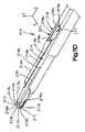
ここで図10A〜Cを参照すると、ロッキングねじ回し200は、別の代替実施形態にしたがって構築することができる。このロッキングねじ回しは、骨ねじ51のような骨アンカー50を骨内に打ち込むように構成することができる。図示した実施形態によると、ロッキングねじ回し200は、第1ガイド部材を画定するシャフト210、摺動部材220をシャフト210に沿って移動するように案内するように第1ガイド部材と係合するように構成された第2ガイド部材を画定する摺動部材220、シャフト210及び摺動部材220と動作可能に連結され、摺動部材220をシャフト210に沿って移動するように構成された作動装置230、及びシャフト210の端に配置されたハンドル240などの多数の構成要素を含むことができる。ロッキングねじ回し200の様々な構成要素は、例えば、市販の純粋なチタン、TANのようなチタン合金、ステンレス鋼、フェノールで補強された亜麻布、ケイ素、Radel(登録商標)、超高分子量ポリエチレン(UHMW)などの任意の好適な材料で作製することができる。   10A-C, the locking screwdriver 200 can be constructed according to another alternative embodiment. This locking screwdriver can be configured to drive a bone anchor 50, such as a bone screw 51, into the bone. According to the illustrated embodiment, the locking screwdriver 200 engages the first guide member to guide the shaft 210 defining the first guide member, the sliding member 220 to move along the shaft 210. An actuating device 230 operatively coupled to the sliding member 220, the shaft 210 and the sliding member 220 defining a second guide member configured to move along the shaft 210. , And a number of components, such as a handle 240 disposed at the end of the shaft 210. The various components of the locking screwdriver 200 include, for example, commercially pure titanium, titanium alloys such as TAN, stainless steel, linen cloth reinforced with phenol, silicon, Radel®, ultra high molecular weight polyethylene ( It can be made of any suitable material such as UHMW).

図示した実施形態によると、シャフト210はシャフト本体212を含み、シャフト本体は、遠位端212aを画定することができる第1端を画定し、更に、例えば長手方向Lであり得る第1の方向に沿って遠位端212aから離間されている近位端212bを画定することができる、反対側の第2端を画定する。シャフト本体212は、例えば、図示したように第1の方向に沿って細長い、外周面212cを画定する概ね円筒形のシャフト本体など、所望の任意の形を有することができる。シャフト本体112は、遠位端212a及び近位端212bによって画定されるシャフトの長さに沿って特定の場所に異なる断面寸法を画定することができる。例えば、シャフト本体212は、例えば長手方向に延在する複数の部位のような少なくとも1つの部位を用いて構築することができ、それぞれの部位は、シャフト本体212の他の部位のそれぞれの断面寸法と異なる少なくとも1つの、例えば直径のような、断面寸法を有する。   According to the illustrated embodiment, the shaft 210 includes a shaft body 212, which defines a first end that can define a distal end 212a, and a first direction that can be, for example, the longitudinal direction L. Defines an opposite second end that can define a proximal end 212b spaced apart from the distal end 212a. The shaft body 212 can have any desired shape, such as, for example, a generally cylindrical shaft body that is elongated along a first direction and defines an outer peripheral surface 212c as shown. The shaft body 112 can define different cross-sectional dimensions at specific locations along the length of the shaft defined by the distal end 212a and the proximal end 212b. For example, the shaft body 212 can be constructed using at least one site, such as, for example, a plurality of longitudinally extending sites, each site having a respective cross-sectional dimension of the other site of the shaft body 212. And at least one cross-sectional dimension, such as a diameter.

図示した実施形態によると、シャフト本体112は複数の長手方向部位を有することができ、それぞれの部位は、複数の部位の他の部位の少なくとも1つの断面寸法とは異なる少なくとも1つの断面寸法を有する。図示したシャフト本体212は、第1又はグリップ部位212dと、第2又は作動装置部位212eと、第3又は中間部位212fと、第4又は先端部位212gと、を含む複数の部位を有する。グリップ部位212dは、シャフト本体212の近位端212bから遠位端212aに向かって延び、第1の断面寸法すなわち直径D8を有する。作動装置部位212eはグリップ部位212dの遠位端からシャフト210の遠位端212aに向かって延び、第1の直径D8より小さい第2の断面寸法すなわち直径D9を有する。作動部位212eにおいてシャフト本体212の外面212cの少なくとも一部分は、以下に詳述するように、作動装置230と動作可能に係合するように構成され得る。中間部位212fは作動装置部位212eの遠位端からシャフト210の遠位端212aに向かって延び、第1の直径D8及び第2の直径D9の両方よりも小さい第3の断面寸法すなわち直径D10を有する。   According to the illustrated embodiment, the shaft body 112 can have a plurality of longitudinal portions, each portion having at least one cross-sectional dimension that is different from at least one cross-sectional dimension of other portions of the plurality of portions. . The illustrated shaft body 212 has a plurality of parts including a first or grip part 212d, a second or actuator part 212e, a third or intermediate part 212f, and a fourth or tip part 212g. The grip portion 212d extends from the proximal end 212b of the shaft body 212 toward the distal end 212a and has a first cross-sectional dimension or diameter D8. Actuator portion 212e extends from the distal end of grip portion 212d toward distal end 212a of shaft 210 and has a second cross-sectional dimension or diameter D9 that is smaller than first diameter D8. At least a portion of the outer surface 212c of the shaft body 212 at the actuation site 212e can be configured to operatively engage the actuation device 230, as described in detail below. The intermediate portion 212f extends from the distal end of the actuator portion 212e toward the distal end 212a of the shaft 210 and has a third cross-sectional dimension or diameter D10 that is smaller than both the first diameter D8 and the second diameter D9. Have.

先端部位212gは中間部位212fの遠位端からシャフト210の遠位端212aまで延在し、先端部位212gの近位端の第3の直径D10と、シャフト210の遠位端212aにおいて、第1の直径D8、第2の直径D9、及び第3の直径D10のそれぞれより小さい第4の断面寸法すなわち直径D11と、の間で先細の断面寸法を有する。例えばシャフト210の遠位端212aのような、先端部位212gの少なくとも一部分は、相補的な骨アンカー50の駆動開口部54に受け入れられるように構成され得る。例えば、図示した実施形態によると、シャフトの遠位端212aは、直径D11が骨アンカー50の駆動開口部54の断面寸法より小さいように構成され得る(図16Aを参照)。シャフト210は図示された部位又は互いに対するそれらの部位の断面寸法に限定されず、シャフト210は代替方法として、所望により他の部位のそれぞれの断面寸法と同じ又は異なるそれぞれの断面寸法を有する任意の他の好適な数の部位で構築されてもよいことを理解されたい。   The tip portion 212g extends from the distal end of the intermediate portion 212f to the distal end 212a of the shaft 210, and at the third diameter D10 of the proximal end of the tip portion 212g and the distal end 212a of the shaft 210, the first end And a fourth cross-sectional dimension smaller than each of the second diameter D8, the second diameter D9, and the third diameter D10, that is, a diameter D11. For example, at least a portion of the tip portion 212g, such as the distal end 212a of the shaft 210, may be configured to be received in the drive opening 54 of the complementary bone anchor 50. For example, according to the illustrated embodiment, the distal end 212a of the shaft can be configured such that the diameter D11 is less than the cross-sectional dimension of the drive opening 54 of the bone anchor 50 (see FIG. 16A). The shafts 210 are not limited to the illustrated sites or the cross-sectional dimensions of those sites relative to each other; the shafts 210 may alternatively have any cross-sectional dimensions that are the same or different from the respective cross-sectional dimensions of other sites, as desired. It should be understood that other suitable numbers of sites may be constructed.

シャフト本体212のグリップ部位212dは、それに配置されたハンドル240のような把持要素を有するように構成され得る。例えば、図示した実施形態によると、ハンドル240は、近位端242bと、第1の方向に沿って近位端242bから離間配置された、反対側の遠位端242aと、第1の方向に対して実質的に垂直に延びる、例えば横方向Aでありうる第2の方向に沿って互いから離間配置された対向側面242cと、を画定するハンドル本体242を含む。ハンドル本体242は、例えば第1の方向に沿って少なくとも部分的にハンドル本体242を通して内に延びる穴244を画定することができ、穴244は、ハンドル240がシャフト210上に配置されたときにシャフト本体212のグリップ部位212dを受け入れるように構成される。ハンドル240がシャフト210上に配置されたら、例えばピン245のような取り付け部材243を使用して、ハンドル240をシャフト210に取り付けること及びシャフト210に対して配向することの一方又は両方が可能である。図示した実施形態によると、グリップ部位212dは、例えば第2の方向に沿ってシャフト本体212を通して少なくとも部分的に内に延びる穴211を画定することができ、穴211はピン245をプレス嵌め係合で受け入れるように寸法決定される。ハンドルは例えばハンドル本体242を通して第2の方向に沿って少なくとも部分的に内に延びる第2の穴246を画定することができ、穴246はピン245をプレス嵌め係合で受け入れるように寸法決定される。ハンドル240がシャフト210に配置され、それに対して正しく配向されると、穴211は穴246と整列し、ピン245を穴211及び246内に挿入することができ、それによって、ハンドル240をシャフト210に対して正しく配向された位置に固定することができる。   The grip portion 212d of the shaft body 212 can be configured to have a gripping element such as a handle 240 disposed thereon. For example, according to the illustrated embodiment, the handle 240 has a proximal end 242b, an opposite distal end 242a spaced from the proximal end 242b along a first direction, and a first direction. A handle body 242 that defines opposing side surfaces 242c that extend substantially perpendicular to each other and that are spaced apart from each other along a second direction, which may be, for example, lateral direction A, is included. The handle body 242 can define a hole 244 that extends, for example, at least partially through the handle body 242 along a first direction, the hole 244 being a shaft when the handle 240 is disposed on the shaft 210. The grip portion 212d of the main body 212 is configured to be received. Once the handle 240 is placed on the shaft 210, it is possible to attach the handle 240 to the shaft 210 and / or to orient it relative to the shaft 210 using an attachment member 243 such as a pin 245, for example. . According to the illustrated embodiment, the grip portion 212d can define a hole 211 that extends at least partially inward through the shaft body 212, for example, along a second direction, the hole 211 press-engaging the pin 245. Sized to accept. The handle can define a second hole 246 that extends, for example, at least partially inward along the second direction through the handle body 242, and the hole 246 is sized to receive the pin 245 in a press-fit engagement. The When the handle 240 is placed on the shaft 210 and properly oriented relative thereto, the hole 211 is aligned with the hole 246 and the pin 245 can be inserted into the holes 211 and 246, thereby attaching the handle 240 to the shaft 210. Can be fixed in a correctly oriented position.

ハンドルの少なくとも一部分は、ハンドル240及びしたがってロッキングねじ回し200が使用中にさらに容易に把持及び操作できるようにするように構成され得る。例えば、ハンドル本体242のそれぞれの対向する側面242cのような少なくとも1つの側面は、それぞれの織り目加工された部分247を画定することができる。図示した実施形態によると、ハンドル本体242の対向する側面242cのそれぞれは、互いに隣接して画定された複数の溝248を備えるそれぞれの織り目加工された部分247を画定し、溝248は第1の方向に対して角度を付けてオフセットされた方向に沿って延在する。ハンドル240の第1の対向する側面242c上で溝248が延在する方向は、もう一方の対向する側面242c上で溝248が延在する方向と同じであってもよく、異なっていてもよい。ロッキングねじ回しは図示したハンドル形状又は取り付け部材に限定されず、ロッキングねじ回し200は、代替方法として、異なるハンドル本体の形状で構築されてもよく、異なる取り付け部材を用いてシャフト210に取り付けられてもよいことを理解されたい。例えば、シャフトのグリップ部位212dは、ハンドル40がロッキングねじ回し200に取り付けられうるように、上述のグリップ部位12cと同様に構成されてもよい。   At least a portion of the handle may be configured to allow the handle 240 and thus the locking screwdriver 200 to be more easily grasped and manipulated during use. For example, at least one side surface, such as each opposing side surface 242c of handle body 242 can define a respective textured portion 247. According to the illustrated embodiment, each of the opposing side surfaces 242c of the handle body 242 defines a respective textured portion 247 comprising a plurality of grooves 248 defined adjacent to each other, the grooves 248 being a first It extends along an offset direction at an angle to the direction. The direction in which the groove 248 extends on the first opposite side 242c of the handle 240 may be the same as or different from the direction in which the groove 248 extends on the other opposite side 242c. . The locking screwdriver is not limited to the illustrated handle shape or mounting member; the locking screwdriver 200 may alternatively be constructed with a different handle body shape and attached to the shaft 210 using a different mounting member. I hope you understand. For example, the grip portion 212d of the shaft may be configured similarly to the grip portion 12c described above so that the handle 40 can be attached to the locking screwdriver 200.

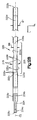
ここで図10A〜C及び11A〜Dを参照すると、シャフト210は、シャフト210に沿って移動するように摺動部材220を方向付けるように摺動部材220によって画定された相補的なガイド部材と係合するように形成された少なくとも1つのガイド部材を含むことができる。図示した実施形態によると、シャフト本体212は、摺動部材220が第1の方向に沿ってチャネル214内を移動することができるように、摺動部材220の少なくとも一部分を受け入れるように形成されたチャネル214の形状の第1ガイド部材を画定する。チャネル214は、シャフト210の遠位端212aから第1の方向に沿って近位端212bに向かって延在することができる。例えば、図示した実施形態によると、チャネル214は、遠位端214aと、第1の方向に沿って遠位端214aから離間配置された対向する近位端214bとの間に延在することができる。図示したチャネル214は、シャフト210のほぼ遠位端212aに配置された遠位端214aから、シャフト本体212の先端部位212g及び中間部位212fを通って、作動装置部位212e内に少なくとも部分的に延び、近位端214bまで延在する。図示したチャネル114は、第1及び第2の方向の両方に対してほぼ垂直に延びる、例えば、横断方向Tでありうる第3の方向に沿って、シャフト本体212内に下方に、又は内向きに、延在する。   Referring now to FIGS. 10A-C and 11A-D, the shaft 210 includes a complementary guide member defined by the sliding member 220 to direct the sliding member 220 to move along the shaft 210. At least one guide member formed to engage may be included. According to the illustrated embodiment, the shaft body 212 is configured to receive at least a portion of the sliding member 220 such that the sliding member 220 can move within the channel 214 along a first direction. A first guide member in the shape of a channel 214 is defined. The channel 214 can extend from the distal end 212a of the shaft 210 along the first direction toward the proximal end 212b. For example, according to the illustrated embodiment, the channel 214 may extend between the distal end 214a and an opposing proximal end 214b spaced from the distal end 214a along a first direction. it can. The illustrated channel 214 extends at least partially from the distal end 214a disposed approximately at the distal end 212a of the shaft 210, through the tip portion 212g and the intermediate portion 212f of the shaft body 212 and into the actuator portion 212e. Extends to the proximal end 214b. The illustrated channel 114 extends generally perpendicular to both the first and second directions, for example, down into the shaft body 212 or inward along a third direction, which may be the transverse direction T. To extend.

チャネル214は、摺動部材220が第1の方向に沿ってチャネル214内を移動することを可能にするために好適な任意の形状を有するように形成され得る。例えば、図示した実施形態によると、チャネル214は、摺動部材220が移動する底面214cと、第3の方向に沿ってそれらの底面214cから上方に、それぞれの側面214dとシャフト本体212の外面212cとの交差点で画定されるそれぞれの上縁214eまで延びる対向側面214dと、を画定するほぼ矩形の断面を有する開口チャネルとして形成される。図示したチャネル214は、シャフト本体212の作動装置部位212eの直径D9及び中間部位212fの直径D10より小さい幅W5を第2の方向に沿って画定する。チャネル214は図示した断面形状に限定されず、チャネル214は、代替方法として、例えば代替的に構築された摺動部材が第1の方向に沿ってチャネル内を移動することを可能にするために、所望の任意の他の好適な断面形状を画定することができることを理解されたい。   The channel 214 may be formed to have any shape suitable to allow the sliding member 220 to move within the channel 214 along the first direction. For example, according to the illustrated embodiment, the channels 214 include a bottom surface 214c on which the sliding member 220 moves, and upwardly from the bottom surface 214c along the third direction, the respective side surfaces 214d and the outer surface 212c of the shaft body 212. And is formed as an open channel having a generally rectangular cross-section defining opposing side surfaces 214d extending to respective upper edges 214e defined at intersections with each other. The illustrated channel 214 defines a width W5 along the second direction that is smaller than the diameter D9 of the actuator portion 212e of the shaft body 212 and the diameter D10 of the intermediate portion 212f. The channel 214 is not limited to the cross-sectional shape shown, but the channel 214 may alternatively be used, for example, to allow an alternatively constructed sliding member to move within the channel along the first direction. It should be understood that any other suitable cross-sectional shape desired can be defined.

シャフト210は、シャフト210の遠位端212aに近接して配置された傾斜部213を少なくとも1つ、例えば複数、例えば一対、含むことができ、傾斜部213は、以下に詳述するように、摺動部材220の少なくとも一部分が骨アンカー50の駆動開口部54内で半径方向に外向きに移動されることを引き起こすように構成される。例えば、図示した実施形態によると、シャフト210は、第3の方向に沿ってチャネル214の底面214cから外向きに延在する一対の傾斜部213を含むことができ、傾斜部213は、第2の方向に沿って互いから離間配置されて、それらの間に隙間を画定する。図示した実施形態によると、傾斜部213はシャフト本体212と一体式でありうる。あるいは、傾斜部213は、シャフト本体212から分離して構築されてから、シャフト本体に取り付けられてもよい。   The shaft 210 can include at least one, for example, a plurality, for example, a pair of ramps 213 disposed proximate to the distal end 212a of the shaft 210, the ramps 213 as detailed below. At least a portion of the sliding member 220 is configured to cause a radially outward movement within the drive opening 54 of the bone anchor 50. For example, according to the illustrated embodiment, the shaft 210 can include a pair of ramps 213 extending outwardly from the bottom surface 214c of the channel 214 along a third direction, the ramps 213 being the second Spaced apart from each other along the direction of, defining a gap therebetween. According to the illustrated embodiment, the inclined portion 213 can be integral with the shaft body 212. Alternatively, the inclined portion 213 may be constructed separately from the shaft body 212 and then attached to the shaft body.

それぞれの傾斜部213は、第1の方向に対して角度を付けてオフセットされた傾斜面213aを画定し、したがって、以下に詳述するように、摺動部材220の対応する部分がそれぞれの傾斜部213の傾斜面213aに沿って進むと、摺動部材220の少なくとも一部分はチャネル214の底面214cに対して半径方向に外向きに移動される。傾斜面213aは、近位端212bから遠位端212aに画定されている方向に沿って延びるにつれて、横断方向Tに沿って外向きに広がることができる。たとえば、傾斜面213aは、所望により、長手方向Lに対して任意の角度を画定することができる。一実施形態によると、傾斜面231は、例えば約45度のような、15度〜75度の範囲の角度を画定する。それぞれの傾斜部213は、それぞれの傾斜部213のそれぞれの傾斜面213aがチャネル214と交差する又は出会うそれぞれの場所213bを更に画定することができる。例えば、図示した実施形態によると、それぞれの傾斜部213の移行位置213bは、骨アンカー50の駆動開口部54の深さL2より短い距離L1にかけてシャフト210の遠位端212aから離間されている(図16Aを参照)。したがって、複数の傾斜部213のそれぞれの移行位置213bは第1の方向に沿ってシャフト210の遠位端212aから等間隔開けて配置される。更に、図示した実施形態によると、それぞれの傾斜部213の傾斜面213aは、それぞれの傾斜部の対応する上端213cとそれぞれの傾斜部213の対応する移行位置213bとの間で一直線である。   Each ramp 213 defines an inclined surface 213a that is angled and offset with respect to the first direction, so that a corresponding portion of the sliding member 220 is tilted as described in detail below. Proceeding along the inclined surface 213 a of the portion 213, at least a portion of the sliding member 220 is moved radially outward with respect to the bottom surface 214 c of the channel 214. The inclined surface 213a can extend outward along the transverse direction T as it extends along the direction defined from the proximal end 212b to the distal end 212a. For example, the inclined surface 213a can define an arbitrary angle with respect to the longitudinal direction L as desired. According to one embodiment, the inclined surface 231 defines an angle in the range of 15 degrees to 75 degrees, such as about 45 degrees. Each ramp 213 can further define a respective location 213 b where each ramp 213 a of each ramp 213 intersects or meets the channel 214. For example, according to the illustrated embodiment, the transition location 213b of each ramp 213 is spaced from the distal end 212a of the shaft 210 over a distance L1 that is shorter than the depth L2 of the drive opening 54 of the bone anchor 50 (see FIG. (See FIG. 16A). Accordingly, the transition positions 213b of the plurality of inclined portions 213 are arranged at equal intervals from the distal end 212a of the shaft 210 along the first direction. Further, according to the illustrated embodiment, the inclined surface 213a of each inclined portion 213 is in a straight line between the corresponding upper end 213c of each inclined portion and the corresponding transition position 213b of each inclined portion 213.

傾斜部213は図示した傾斜面213aに限定されず、例えば傾斜部213のそれぞれなど少なくとも1つの傾斜部の傾斜面213aは、代替方法として、所望により任意の他の表面形状を使用して構成され得ることを理解されたい。例えば、傾斜部213のそれぞれなど、少なくとも1つの傾斜部の傾斜面213aは、傾斜部213のそれぞれの上端213cと傾斜部213のそれぞれの移行位置213bとの間で少なくとも部分的に曲線であってもよい。複数の傾斜部213のそれぞれの移行位置213bはシャフト210の遠位端212aから等間隔に配置されていなくてもよいことを更に理解されたい。例えば、複数の傾斜部213の2つ目の傾斜面213aが第1の方向に対して角度を付けてオフセットされている角度より第1の方向に対してより浅い又は急な角度で角度を付けてオフセットされた傾斜面213aを複数の傾斜部213の最初の1つが画定するように、複数の傾斜部213の少なくとも最初の1つの移行位置213bが複数の傾斜部213の2つ目の移行位置213bよりシャフト210の遠位端212aから遠くに又はそれにより近くに離間配置されてもよい。   The inclined portion 213 is not limited to the illustrated inclined surface 213a. For example, the inclined surface 213a of at least one inclined portion such as each of the inclined portions 213 may be configured using any other surface shape as desired as an alternative method. Please understand that you get. For example, the inclined surface 213a of at least one inclined portion, such as each of the inclined portions 213, is at least partially curved between each upper end 213c of the inclined portion 213 and each transition position 213b of the inclined portion 213. Also good. It should be further understood that each transition location 213b of the plurality of ramps 213 may not be equally spaced from the distal end 212a of the shaft 210. For example, the second inclined surface 213a of the plurality of inclined portions 213 is angled at a shallower or steeper angle with respect to the first direction than the angle at which the second inclined surface 213a is offset with respect to the first direction. At least the first transition position 213b of the plurality of inclined portions 213 is the second transition position of the plurality of inclined portions 213 so that the first one of the plurality of inclined portions 213 defines the inclined surface 213a offset with It may be spaced farther from or closer to the distal end 212a of the shaft 210 than 213b.

シャフト110は、更に、例えばチャネル214内に摺動部材220を保持するように構成された複数の保持部材215を少なくとも1つ含むことができる。例えば、シャフト210は、摺動部材220の少なくとも一部分を捉えるように、チャネル214の対向する側面214dに対して内向きに延びる複数の保持部材215を含むことができる。保持部材215は、摺動部材220が、例えばシャフト本体212の外面212cによって画定された輪郭であるシャフト210の輪郭を越えて突出しないように、チャネル214内に摺動部材220を保持するように構成され得る。図示した実施形態によると、シャフト210は、横方向に対向した弧状突出部216を含む一対の保持部材215を含み、それぞれの弧状突出部216は、チャネル214の対向する側面214dのそれぞれの側のそれぞれの上縁214eから上方にかつ内向きに延在する少なくとも1つの上部216aを備える。以下に詳述するように、弧状突出部216の上部216aは、チャネル214内で摺動部材220のそれぞれの部分を捉えるように、したがって摺動部材220をチャネル214内に保持するように構成される。図示した実施形態によると、弧状突出部216の上部216aは、チャネル214の上縁214eに対して上方に延び、且つ、チャネル214のそれぞれの上縁214eに実質的に配置された内端216cと、チャネル214のそれぞれの対向する側面214dから第2の方向に沿って内向きに離間配置された反対側の外端216bと、の間で、チャネル214の対向する側面214dに対して内向きに延びることができる。弧状突出部216の上部216aのそれぞれの外端216bは、外端216bの間に隙間216dが画定されるように互いから離間配置されてよく、隙間216dは、チャネル214の幅W5より短い第2の方向に沿って幅W6を有する。   The shaft 110 can further include at least one holding member 215 configured to hold the sliding member 220 within the channel 214, for example. For example, the shaft 210 can include a plurality of retaining members 215 that extend inward relative to opposing side surfaces 214 d of the channel 214 to capture at least a portion of the sliding member 220. The retaining member 215 retains the sliding member 220 in the channel 214 such that the sliding member 220 does not protrude beyond the contour of the shaft 210, for example, the contour defined by the outer surface 212c of the shaft body 212. Can be configured. According to the illustrated embodiment, the shaft 210 includes a pair of retaining members 215 that include laterally opposed arcuate protrusions 216, each arcuate protrusion 216 on each side of the opposing side surface 214 d of the channel 214. At least one upper portion 216a extending upward and inward from each upper edge 214e is provided. As will be described in detail below, the upper portion 216 a of the arcuate protrusion 216 is configured to capture a respective portion of the sliding member 220 within the channel 214 and thus retain the sliding member 220 within the channel 214. The According to the illustrated embodiment, the upper portion 216 a of the arcuate protrusion 216 extends upwardly with respect to the upper edge 214 e of the channel 214, and an inner end 216 c that is substantially disposed on each upper edge 214 e of the channel 214. Between the opposing outer side 216b spaced inward along the second direction from each opposing side 214d of the channel 214 and inward with respect to the opposing side 214d of the channel 214. Can extend. Each outer end 216b of the upper portion 216a of the arcuate protrusion 216 may be spaced apart from each other such that a gap 216d is defined between the outer ends 216b, the gap 216d being a second shorter than the width W5 of the channel 214. It has a width W6 along the direction of.

それぞれの弧状突出部216は、上部216aの外端216bに対して下方に、且つチャネル214のそれぞれの対向する側面214dに対して内向きに延びる、下部216eを更に備えることができる。それぞれの弧状突出部の上部216a及び下部216eは、チャネル214のそれぞれの対向する側面214dから内向きに離間配置されたそれぞれの溝217を画定することができ、以下に詳述するように、溝217は、摺動部材220の少なくとも一部分を摺動可能に受け入れ、保持するように構成される。チャネル214の対向する側面214dのそれぞれの上の弧状突出部216は、弧状突出部216が、第2の方向に沿って互いに面する横方向に対向する一対の溝217を画定するように、実質的に同一に構築され得る。シャフト210は図示した保持部材215に限定されず、シャフト210は、代替方法として、所望により任意の他の好適な保持部材を用いて構築されてもよいことを理解されたい。図示した実施形態によると、保持部材215はシャフト本体212と一体式でありうる。あるいは、保持部材215は、シャフト本体212から分離して構築されてから、シャフト本体に取り付けられてもよい。   Each arcuate protrusion 216 can further comprise a lower portion 216e that extends downwardly relative to the outer end 216b of the upper portion 216a and inwardly with respect to each opposing side surface 214d of the channel 214. The upper and lower portions 216a and 216e of each arcuate protrusion can define respective grooves 217 spaced inwardly from respective opposing side surfaces 214d of the channel 214, as described in detail below. 217 is configured to slidably receive and retain at least a portion of the sliding member 220. The arcuate protrusions 216 on each of the opposing side surfaces 214d of the channel 214 are substantially such that the arcuate protrusions 216 define a pair of laterally opposed grooves 217 that face each other along the second direction. Can be constructed identically. It should be understood that the shaft 210 is not limited to the illustrated retention member 215 and that the shaft 210 may alternatively be constructed using any other suitable retention member as desired. According to the illustrated embodiment, the retaining member 215 can be integral with the shaft body 212. Alternatively, the holding member 215 may be constructed separately from the shaft body 212 and then attached to the shaft body.

ここで図10A〜B及び12A〜Eを参照すると、図示した実施形態によると、摺動部材220は、摺動部材本体すなわち、遠位端を画定しうる第1端222aと、近位端を画定しうる、第1の方向に沿って第1端222aから離間配置された、対向する第2端222bと、の間に延在する摺動本体222、及び第2の方向に沿って互いから離間配置された対向側面222cを含む。摺動部材220は、摺動部材220を、シャフト210に沿って移動するように、及び少なくとも1つの傾斜部に例えば複数の傾斜部213のそれぞれに向けて方向付けるように、シャフト210によって画定された相補的なガイド部材と係合するように構成された少なくとも1つのガイド部材を含むことができる。例えば、摺動部材220は、シャフト210の第1のガイド部材と係合するように構成された第2のガイド部材を画定することができる。図示した実施形態によると、シャフト本体222は、チャネル214の底面214cに沿って移動するように構成された下位面又は摺動面222d、及び第3の方向に沿って摺動面222dから離間配置された対向する上位面又は外面222eの形状のガイド部材を画定する。摺動本体222は、所望により任意の形を有することができ、例えば、図示した摺動本体222は、対向する側面222cと摺動面222dによって画定された概ね矩形の下部と、摺動部材220がチャネル214内に配置されたときにシャフト本体212の外面212cの輪郭とほぼ一致するように構成された外面222eによって画定される湾曲した上部と、を有する断面を有する。   Referring now to FIGS. 10A-B and 12A-E, according to the illustrated embodiment, the sliding member 220 includes a sliding member body, ie, a first end 222a that can define a distal end, and a proximal end. A sliding body 222 extending between an opposing second end 222b, spaced apart from the first end 222a along a first direction, and from each other along a second direction that can be defined It includes opposed side surfaces 222c that are spaced apart. The sliding member 220 is defined by the shaft 210 to move the sliding member 220 along the shaft 210 and to direct the at least one inclined portion toward, for example, each of the plurality of inclined portions 213. And at least one guide member configured to engage the complementary guide member. For example, the sliding member 220 can define a second guide member configured to engage with the first guide member of the shaft 210. According to the illustrated embodiment, the shaft body 222 is spaced from the lower or sliding surface 222d configured to move along the bottom surface 214c of the channel 214 and the sliding surface 222d along the third direction. A guide member in the shape of the opposed upper or outer surface 222e is defined. The sliding body 222 can have any shape as desired. For example, the illustrated sliding body 222 includes a generally rectangular lower portion defined by opposing side surfaces 222c and a sliding surface 222d, and a sliding member 220. Having a curved top defined by an outer surface 222e configured to substantially match the contour of the outer surface 212c of the shaft body 212 when disposed in the channel 214.

ロッキングねじ回し200は、例えばチャネル214の形状の第1のガイド部材及び摺動面212dの形状の第2のガイド部材のような図示したガイド部材に限定されず、ロッキングねじ回し200は代替方法として所望により任意の他の好適なガイド部材を含むことができることを理解されたい。例えば、代替実施形態によると、シャフト210はシャフト本体212の外面212cから外向きに延在する第1ガイド部材を含むことができ、第1ガイド部材は、摺動本体222の外面222e内に延びる相補的な第2ガイド部材に受け取られるように構成される。   The locking screwdriver 200 is not limited to the illustrated guide members such as the first guide member in the shape of the channel 214 and the second guide member in the shape of the sliding surface 212d, but the locking screwdriver 200 is an alternative method. It should be understood that any other suitable guide member can be included as desired. For example, according to an alternative embodiment, the shaft 210 can include a first guide member that extends outwardly from the outer surface 212 c of the shaft body 212, the first guide member extending into the outer surface 222 e of the sliding body 222. It is configured to be received by a complementary second guide member.

例えば第1端222aのような、摺動部材220の少なくとも一部分は、相補的な骨アンカー50の駆動開口部54に受け入れられるように構成され得る。更に、以下に詳述するように、摺動部材220の第1端222aは、シャフト210の遠位端212aと同時に骨アンカー50の駆動開口部54内に配置されるように構成され得る。   At least a portion of the sliding member 220, such as the first end 222a, can be configured to be received in the drive opening 54 of the complementary bone anchor 50. Further, as described in detail below, the first end 222a of the sliding member 220 may be configured to be disposed in the drive opening 54 of the bone anchor 50 at the same time as the distal end 212a of the shaft 210.

摺動本体222は、例えば対向する側面222cによって画定される第2の方向に沿って幅W7を有することができ、幅W7はチャネル214の幅W5とおよそ同等であるが短く、したがって、摺動部材220がチャネル214内に配置されたとき、摺動部材220はチャネル214内で第1の方向に沿って自由に動くこと又は移動することができる。摺動部材220は、摺動本体222の対向する側面222cが他方に対して幅W7より遠くに離間されないように構築され得る。摺動部材220は、例えば摺動本体222の第1端222aと第2端222bによって画定されるような第1の方向に沿った長さを有することができ、この長さは、例えばチャネル214の遠位端214aと近位端214bによって画定されるような第1の方向に沿ったチャネル214の長さより短い。例えば、図示した実施形態によると、摺動部材220がチャネル214の近位端214bにて実質的に配置された摺動部材220の第2端222bを有するチャネル214内に配置される時に、摺動部材220の第1端222aがシャフト210の遠位端212aから近位に配置される、より具体的には複数の傾斜213の全てなどの少なくとも1つにおけるそれぞれの移行位置213bに対して近位に配置されるように、摺動部材220は構築することができる。   The sliding body 222 can have a width W7, for example, along a second direction defined by the opposing side surfaces 222c, which is approximately equal to the width W5 of the channel 214, but is short and therefore sliding. When member 220 is disposed within channel 214, sliding member 220 is free to move or move within the channel 214 along a first direction. The sliding member 220 can be constructed such that the opposing side surfaces 222c of the sliding body 222 are not separated further than the width W7 with respect to the other. The sliding member 220 can have a length along a first direction as defined by, for example, the first end 222a and the second end 222b of the sliding body 222, which length can be, for example, the channel 214. Shorter than the length of the channel 214 along the first direction as defined by its distal end 214a and proximal end 214b. For example, according to the illustrated embodiment, when the sliding member 220 is disposed in the channel 214 having the second end 222b of the sliding member 220 disposed substantially at the proximal end 214b of the channel 214, the sliding member 220 is slid. The first end 222a of the moving member 220 is disposed proximally from the distal end 212a of the shaft 210, and more specifically near each transition position 213b in at least one such as all of the plurality of ramps 213. The sliding member 220 can be constructed so that it is positioned in place.

ロッキングねじ回し200は、シャフト210の遠位端212a及び摺動部材220の第1端222aが骨アンカー50の駆動開口部54に対して自由に挿入又は取出しされ得る後退した構成と、シャフト210の遠位端212a及び摺動部材220の第1端222aが骨アンカー50の駆動開口部54内に解放可能にロックされている解放可能にロックされた構成との間で動作することができる。後退した構成から解放可能にロックされた構成にロッキングねじ回し200を動作することは、骨アンカー50の駆動開口部54内で摺動部材220がシャフト210に対する第1のすなわち後退した位置から、第2のすなわち解放可能にロックされた位置に動作されることを引き起こすことができる。   The locking screwdriver 200 includes a retracted configuration in which the distal end 212a of the shaft 210 and the first end 222a of the sliding member 220 can be freely inserted or removed from the drive opening 54 of the bone anchor 50, and The distal end 212 a and the first end 222 a of the sliding member 220 can operate between a releasably locked configuration in which the distal end 212 a is releasably locked within the drive opening 54 of the bone anchor 50. Operating the locking screwdriver 200 from the retracted configuration to the releasably locked configuration causes the sliding member 220 to move from a first or retracted position relative to the shaft 210 within the drive opening 54 of the bone anchor 50. It can be caused to be moved to the two or releasably locked positions.

作動装置230を動作することによって、後退した位置から解放可能にロックされた位置に摺動部材220を動作することができる。作動装置230を動作すると、作動装置230は、摺動部材220を付勢してシャフト210に沿って例えば長手方向Lでありうる第1の方向に、シャフト210の遠位端212aに向かって、解放可能にロックされた位置へと移動させる力を摺動部材220に付加することができる。摺動部材220の第1端222aは、摺動部材220が後退した位置から解放可能にロックされた位置へと移動するときに傾斜部213に沿って進み、それによって摺動部材220の少なくとも第1端222aを骨アンカー50の駆動開口部54内で半径方向に外向きに移動させ、骨アンカー50の駆動開口部54内でシャフト210の遠位端212aと摺動部材220の第1端222aとを解放可能にロックするように構成され得る。換言すると、摺動部材220及びシャフト210の遠位端212aが駆動開口部54内に配置され、摺動部材220が解放可能にロックされた位置にあるとき、ロッキングねじ回し200は骨アンカー50に解放可能にロックされている。   By operating the actuator 230, the sliding member 220 can be moved from the retracted position to the releasably locked position. Upon actuation of the actuator 230, the actuator 230 biases the sliding member 220 toward the distal end 212a of the shaft 210 in a first direction along the shaft 210, which may be, for example, the longitudinal direction L. A force can be applied to the sliding member 220 to move it to a releasably locked position. The first end 222a of the sliding member 220 advances along the ramp 213 when the sliding member 220 moves from the retracted position to the releasably locked position, thereby at least the first of the sliding member 220. One end 222a is moved radially outwardly within the drive opening 54 of the bone anchor 50, and within the drive opening 54 of the bone anchor 50, the distal end 212a of the shaft 210 and the first end 222a of the sliding member 220. Can be releasably locked. In other words, the locking screwdriver 200 is attached to the bone anchor 50 when the sliding member 220 and the distal end 212a of the shaft 210 are disposed within the drive opening 54 and the sliding member 220 is in a releasably locked position. It is locked releasably.

摺動部材220の第1端222aは、例えば複数のライディング面223のような少なくとも1つのライディング面を画定することができ、それぞれのライディング面は、例えばロッキングねじ回し200が後退した構成から解放可能にロックされた構成に動作されたときに、複数の傾斜部213のそれぞれのものに沿って進むように構成される。図示した実施形態によると、摺動部材220の第1端222aは、第2の方向に沿って互いから離間配置された一対のライディング面223を画定する。ライディング面223は第1の方向に対して角度を付けてオフセットされている。図示したライディング面223は、傾斜部の傾斜面213aが第1の方向に対して角度を付けてオフセットされている角度と実質的に同等の角度で第1の方向に対して角度を付けてオフセットされている。しかし、複数のライディング面223のそれぞれのような少なくとも1つのライディング面は、対応する傾斜部の傾斜面213aのそれぞれが第1の方向に対して角度を付けてオフセットされている角度より浅い又は急なそれぞれの角度で第1の方向に対して角度を付けてオフセットされ得ることを理解されたい。   The first end 222a of the sliding member 220 can define at least one riding surface, such as a plurality of riding surfaces 223, for example, each riding surface being releasable from a configuration in which the locking screwdriver 200 is retracted, for example. When operated in the locked configuration, each of the plurality of inclined portions 213 is configured to travel along the respective one. According to the illustrated embodiment, the first end 222a of the sliding member 220 defines a pair of riding surfaces 223 that are spaced apart from each other along the second direction. The riding surface 223 is offset at an angle with respect to the first direction. The illustrated riding surface 223 is offset with respect to the first direction at an angle substantially equal to the angle at which the inclined surface 213a of the inclined portion is offset with respect to the first direction. Has been. However, at least one riding surface, such as each of the plurality of riding surfaces 223, is shallower or steeper than the angle at which each of the inclined surfaces 213a of the corresponding inclined portion is offset with respect to the first direction. It should be understood that each angle may be offset at an angle relative to the first direction.

摺動部材220は、摺動部材220の1つ以上の構造特性を向上するように構成された複数の構造部材のような少なくとも1つの構造部材を含むことができる。例えば、少なくとも1つの構造部材は、摺動部材220に安全に付与され得る回転力の量を増すように作用しうる。図示した実施形態によると、摺動部材220は、例えば、摺動本体222の摺動面222dから外向きに延びる摺動部材220によって支持された突起224のような少なくとも1つの構造部材を含むことができる。突起224は、第1端すなわち遠位端224a、第1の方向に沿って遠位端224aから離間配置された対向する第2端すなわち近位端224bと、第2の方向に沿って互いから離間配置された対向側面224cとの間に延在することができる。図示した突起224は、摺動部材220の第1端222aから第1の方向に沿って第2端222bに向かって延在することができる。例えば、図示した実施形態によると、突起224は、第1の方向に対して実質的に平行に延在する摺動部材220の中心線C2に沿って、且つ摺動本体222の対向する側面222cの間に等距離に、延在することができる。更に、図示した突起224は第3の方向に沿って摺動面222dから外向きに、又は下方に延在することができる。図示した実施形態によると、摺動本体222は、一対のライディング面223を画定し、それぞれのライディング面223は突起224の対向する側面224cのそれぞれの一方に隣接して配置される。   The sliding member 220 can include at least one structural member, such as a plurality of structural members configured to improve one or more structural characteristics of the sliding member 220. For example, the at least one structural member can act to increase the amount of rotational force that can be safely applied to the sliding member 220. According to the illustrated embodiment, the sliding member 220 includes at least one structural member, such as a protrusion 224 supported by the sliding member 220 that extends outwardly from the sliding surface 222d of the sliding body 222, for example. Can do. The protrusions 224 have a first or distal end 224a, opposing second or proximal ends 224b spaced from the distal end 224a along a first direction, and from each other along a second direction. It can extend between the opposed side surfaces 224c that are spaced apart. The illustrated protrusion 224 can extend from the first end 222a of the sliding member 220 along the first direction toward the second end 222b. For example, according to the illustrated embodiment, the protrusion 224 is along the center line C2 of the sliding member 220 extending substantially parallel to the first direction and the opposite side surface 222c of the sliding body 222. Can be extended equidistantly. Further, the illustrated protrusion 224 can extend outwardly or downwardly from the sliding surface 222d along the third direction. According to the illustrated embodiment, the sliding body 222 defines a pair of riding surfaces 223, each riding surface 223 disposed adjacent to one of the opposing side surfaces 224 c of the protrusion 224.

ここで図11A〜D及び12A〜Eを参照すると、シャフト210は、突起224を受け入れように寸法決定された溝218を画定することができる。図示した実施形態によると、溝218は第3の方向に沿ってチャネル214の底面214c内に延在することができる。溝218は、第1端すなわち遠位端218a、第1の方向に沿って遠位端218aから離間配置された対向する第2端すなわち近位端218bとの間に延在することができ、第2の方向に沿って互いから離間配置された対向側面218cを画定することができる。図示した溝218は、シャフト210の遠位端212aから近位端212bに向かって、第1の方向に対して実質的に平行に延びるシャフト210の中心線C1に沿って延在する。更に、図示した溝218は、第3の方向に沿ってシャフト本体212内に延びる。図示した実施形態によると、複数の傾斜部213は一対の傾斜部213を備え、一対の傾斜部213のそれぞれの傾斜部213は溝218の対向する側面218cのそれぞれの1つに隣接して配置される。   Referring now to FIGS. 11A-D and 12A-E, the shaft 210 can define a groove 218 that is sized to receive the protrusion 224. According to the illustrated embodiment, the groove 218 can extend into the bottom surface 214c of the channel 214 along the third direction. The groove 218 can extend between a first or distal end 218a and an opposing second or proximal end 218b spaced from the distal end 218a along a first direction; Opposing side surfaces 218c can be defined that are spaced apart from each other along the second direction. The illustrated groove 218 extends from the distal end 212a of the shaft 210 toward the proximal end 212b along a centerline C1 of the shaft 210 that extends substantially parallel to the first direction. Further, the illustrated groove 218 extends into the shaft body 212 along the third direction. According to the illustrated embodiment, the plurality of inclined portions 213 includes a pair of inclined portions 213, and each inclined portion 213 of the pair of inclined portions 213 is disposed adjacent to each one of the opposing side surfaces 218 c of the groove 218. Is done.

突起224は、摺動部材220が後退した位置から解放可能にロックされた位置へと動作されるときに突起224が溝218内で移動することができるように、溝218内に受け入れられるように形成され得る。例えば、図示した実施形態によると、溝218は、例えば、遠位端218a及び近位端218bによって画定されるような第1の方向に沿った長さを画定することができ、この長さは、例えば遠位端224a及び近位端224bによって画定されるような第1の方向に沿った突起224の長さより長い。溝218と突起224の一方又は両方は、更に、摺動部材220がシャフト210に対して第1の方向に沿って移動されるときに突起224が溝218と接触しないように構成され得る。例えば、図示した実施形態によると、溝218は第1の方向に対して角度を付けてオフセットされた傾斜面218dを画定し、突起224は第1の方向に対して角度を付けてオフセットされた傾斜面224dを画定する。後退した位置から解放可能にロックされた位置にロッキングねじ回し200を動作する間、突起224は、突起224の傾斜面224dが溝218の傾斜面218dと接触しないように溝218内を遠位に移動することになる。   The protrusion 224 is received within the groove 218 such that the protrusion 224 can move within the groove 218 when the sliding member 220 is moved from the retracted position to the releasably locked position. Can be formed. For example, according to the illustrated embodiment, the groove 218 can define a length along a first direction, for example, as defined by the distal end 218a and the proximal end 218b, the length being Longer than the length of the protrusion 224 along the first direction, eg, as defined by the distal end 224a and the proximal end 224b. One or both of the groove 218 and the protrusion 224 may be further configured such that the protrusion 224 does not contact the groove 218 when the sliding member 220 is moved along the first direction relative to the shaft 210. For example, according to the illustrated embodiment, the groove 218 defines an inclined surface 218d that is angled and offset with respect to a first direction, and the protrusion 224 is angled and offset with respect to the first direction. An inclined surface 224d is defined. While operating the locking screwdriver 200 from the retracted position to the releasably locked position, the protrusion 224 moves distally within the groove 218 such that the inclined surface 224d of the protrusion 224 does not contact the inclined surface 218d of the groove 218. Will move.

ロッキングねじ回し200は図示した突起224及び溝218に限定されずに、ロッキングねじ回し200は、代替方法として任意の他の好適な構成の突起224及び溝218を有するように構築され得ることを理解されたい。例えば、代替実施形態によると、ロッキングねじ回し200は、代替方法として複数の突起224及び対応する複数の溝218を有するように構築され得る。別の代替実施形態では、突起224は、第3の方向に対して角度を付けてオフセットされる方向に沿って摺動本体222の摺動面222dから外向きに延在することができる。もちろん、溝218は、代替方法として溝内に突起224の移動を受容するように構成されてもよい。また別の代替実施形態によると、突起224は、第1の方向と実質的に平行だが摺動本体222の中心線C2に対して横方向にオフセットされた方向に沿って延在することができる。もちろん、溝218は、溝218内に突起224の移動を受容するようにシャフト本体212の中心線C1に対して同様に横方向にオフセットされてもよい。摺動部材220の突起224及びシャフト210の溝218のそれぞれの、一方又は両方は所望により、代替方法として上記の代替実施形態の任意の組み合わせを利用して構成されてもよいことを更に理解されたい。   It will be appreciated that the locking screwdriver 200 is not limited to the illustrated protrusions 224 and grooves 218, but that the locking screwdriver 200 may alternatively be constructed to have any other suitable configuration of protrusions 224 and grooves 218. I want to be. For example, according to alternative embodiments, the locking screwdriver 200 can be constructed to have a plurality of protrusions 224 and a corresponding plurality of grooves 218 as an alternative. In another alternative embodiment, the protrusion 224 can extend outwardly from the sliding surface 222d of the sliding body 222 along a direction that is angled and offset with respect to the third direction. Of course, the groove 218 may alternatively be configured to accept movement of the protrusion 224 within the groove. According to yet another alternative embodiment, the protrusion 224 can extend along a direction that is substantially parallel to the first direction but offset laterally with respect to the centerline C2 of the sliding body 222. . Of course, the groove 218 may be similarly offset laterally with respect to the centerline C1 of the shaft body 212 to receive movement of the protrusion 224 within the groove 218. It will further be appreciated that one or both of the protrusion 224 of the sliding member 220 and the groove 218 of the shaft 210 may be configured utilizing any combination of the above alternative embodiments as an alternative, if desired. I want.

引き続き図11A〜D及び12A〜Eを参照すると、摺動部材220の少なくとも一部分はシャフト210の保持部材215と、具体的にはその弧状突出部216と協働するように構成され得る。例えば、摺動本体222は、弧状突出部216の外端216bの間の隙間216dの幅W6とおよそ同等だがより短い第2の方向に沿った幅W8を有する保持部位225を画定することができ、したがって、保持部位225の少なくとも一部分は弧状突出部216の間の隙間216dを通してチャネル214内に配置され得る。図示した実施形態によると、保持部位225は、摺動部材220の第1端222aに対して近位に位置づけられた第1端すなわち遠位端225a、第1の方向に沿って遠位端225aから近位に離間配置された第2端又は近位端225b、及び対向する側面222cから内向きに第2の方向に沿って離間配置された対向側面225cの間に延在する。   With continued reference to FIGS. 11A-D and 12A-E, at least a portion of the sliding member 220 may be configured to cooperate with the retaining member 215 of the shaft 210 and specifically its arcuate protrusion 216. For example, the sliding body 222 can define a holding portion 225 having a width W8 along the second direction that is approximately equal to but shorter than the width W6 of the gap 216d between the outer ends 216b of the arcuate protrusions 216. Thus, at least a portion of the retention site 225 may be disposed in the channel 214 through the gap 216d between the arcuate protrusions 216. According to the illustrated embodiment, the retention site 225 has a first or distal end 225a positioned proximal to the first end 222a of the sliding member 220, a distal end 225a along the first direction. Extending proximally from a second end or proximal end 225b and an opposing side surface 225c spaced inwardly along the second direction from the opposing side surface 222c.

摺動部材220は、チャネル214内に摺動部材220を保持するように構成された複数の保持部材215のような少なくとも1つの保持部材を含むことができる。摺動部材220の保持部材215は、シャフト210の保持部材215と協働するように構成され得る。例えば、図示した実施形態によると、摺動部材220は、摺動本体222の保持部位225に画定された一対の保持翼部226の形状の複数の保持部材215を含む。それぞれの保持翼部226は、実質的に保持部位225の遠位端225aに配置され得る第1の端すなわち遠位端226aと、第1の方向に沿って遠位端226aから近位に離間配置された対向する第2端すなわち近位端226bとの間に延在することができ、第2の方向に沿って対向する側面225cのそれぞれの一方から外側面226cまで外向きに延在することができる。図示した実施形態によると、保持翼部226のそれぞれの外側面226cは、摺動本体222の対向する側面222cの対応する一方と実質的に一致することができる。   The sliding member 220 can include at least one holding member, such as a plurality of holding members 215 configured to hold the sliding member 220 in the channel 214. The holding member 215 of the sliding member 220 can be configured to cooperate with the holding member 215 of the shaft 210. For example, according to the illustrated embodiment, the sliding member 220 includes a plurality of holding members 215 in the form of a pair of holding wings 226 defined in a holding portion 225 of the sliding body 222. Each retention wing 226 is substantially spaced proximally from the distal end 226a along a first direction with a first or distal end 226a that can be disposed substantially at the distal end 225a of the retention site 225. Can extend between the opposite opposed second or proximal ends 226b and extends outwardly from one of the opposing side surfaces 225c along the second direction to the outer surface 226c. be able to. According to the illustrated embodiment, each outer surface 226 c of the retaining wing 226 can substantially coincide with a corresponding one of the opposing side surfaces 222 c of the sliding body 222.

それぞれの保持翼部226の近位端226bは、それぞれの保持翼部226の近位端226bと保持部位225の近位端225bとによって画定される第1の方向に沿った長さL3が弧状突出部216のそれぞれの第1の方向に沿った長さL4とほぼ同等だがより長くなるように、保持部位225の遠位端225aからある距離に位置づけることができ、したがって、保持部位225の、少なくともそれぞれの保持翼部226の近位端226bから近位端225bに延在する部分は、弧状突出部216を通り越してチャネル214内に配置され得る。それぞれの保持翼部226は、摺動部材220がチャネル214内に配置されるときに保持翼部226が弧状突出部216の対応する一方によって、具体的には弧状突出部216の対応する一方によって画定された溝217によって、入れ子状の係合において少なくとも部分的に受け入れられうるように構成され得る。例えば、図示した実施形態によると、それぞれの保持翼部226の断面の輪郭は、それぞれの保持翼部226が弧状突出部216によって画定された溝217の対応する一方によって受け入れられうるように構成され得る。以下に詳述するように、ロッキングねじ回し200の後退構成と解放可能にロックされた構成との間の動作中、保持翼部226は、一対の保持翼部226と一対の弧状突出部216との間の係合が摺動部材220をチャネル214内に保持するように、溝217内に係合することができる。それぞれの保持翼部226は、ロッキングねじ回し200が後退構成と解放可能にロックされた構成との間で動作される際に、それぞれの保持翼部226の入れ子状の係合をそれぞれの1つの弧状突出部216によって画定された対応する溝217内に維持するのに十分である、例えば遠位端226aと近位端226bとによって画定されるような第1の方向に沿った長さを有することができる。   The proximal end 226b of each retaining wing 226 has an arcuate length L3 along a first direction defined by the proximal end 226b of each retaining wing 226 and the proximal end 225b of the retaining portion 225. The protrusion 216 can be positioned at a distance from the distal end 225a of the retention site 225 so as to be approximately equal to, but longer than, the length L4 along each first direction of the protrusion 216, and thus, At least a portion of each retaining wing 226 that extends from the proximal end 226 b to the proximal end 225 b may be disposed in the channel 214 past the arcuate protrusion 216. Each holding wing 226 has a holding wing 226 that corresponds to one of the arcuate protrusions 216 when the sliding member 220 is disposed in the channel 214, and specifically, corresponds to one of the arcuate protrusions 216. The defined groove 217 may be configured to be at least partially received in a nested engagement. For example, according to the illustrated embodiment, the cross-sectional profile of each retaining wing 226 is configured such that each retaining wing 226 can be received by a corresponding one of the grooves 217 defined by the arcuate protrusion 216. obtain. As will be described in detail below, during operation between the retracted configuration of the locking screwdriver 200 and the releasably locked configuration, the retaining wings 226 include a pair of retaining wings 226 and a pair of arcuate protrusions 216. Can be engaged in the groove 217 such that the engagement between the two retains the sliding member 220 in the channel 214. Each retaining wing 226 engages a nested engagement of each retaining wing 226 when the locking screwdriver 200 is operated between a retracted configuration and a releasably locked configuration. Having a length along a first direction sufficient to maintain within a corresponding groove 217 defined by arcuate protrusions 216, for example, as defined by distal end 226a and proximal end 226b be able to.

ここで図10A〜B及び12A〜Eを参照すると、摺動部材220の第2端222bは、作動装置230の動作によって摺動部材が後退構成と解放可能にロックされた構成との間で移動するように、作動装置230に動作可能に連結されるように構成され得る。例えば、摺動部材220は、複数の連結部材228のような少なくとも1つの連結部材を含むことができ、連結部材228は作動装置230に受け入れられるように構成される。図示した実施形態によると、摺動部材220は、第3の方向に沿って摺動部材220の第2端222bに近接した摺動部材220から外向きに延在するツメ229の形状の一対の連結部材228を含む。具体的には、一対のツメ229のそれぞれは、第3の方向に沿って摺動本体222の外面222eから横断方向に上方に延在することができる。一対のツメ229の第1のツメ229aは、実質的に摺動部材220の第2端222bに配置され得る。一対のツメ229の第2のツメ229bは、一対のツメ229の第1及び第2のツメ229a及び229bが第1の方向に沿って互いから離間配置されるように、第1のツメ229aに対して遠位に配置され得る。   Referring now to FIGS. 10A-B and 12A-E, the second end 222b of the sliding member 220 is moved between a retracted configuration and a releasably locked configuration by operation of the actuator 230. As such, it can be configured to be operably coupled to the actuator 230. For example, the sliding member 220 can include at least one connecting member, such as a plurality of connecting members 228, which are configured to be received by the actuator 230. According to the illustrated embodiment, the sliding member 220 is a pair of tabs 229 in the shape of claws 229 extending outwardly from the sliding member 220 proximate to the second end 222b of the sliding member 220 along the third direction. A connecting member 228 is included. Specifically, each of the pair of claws 229 can extend upward in the transverse direction from the outer surface 222e of the sliding body 222 along the third direction. The first claw 229a of the pair of claws 229 may be disposed substantially at the second end 222b of the sliding member 220. The second claw 229b of the pair of claws 229 is formed on the first claw 229a such that the first and second claws 229a and 229b of the pair of claws 229 are spaced apart from each other along the first direction. It can be arranged distally with respect to.

ここで図13及び14A〜Cを参照すると、作動装置230が動作されたときに摺動部材220が第1の方向に沿ってチャネル214内を移動するように、摺動部材220は作動装置230に動作可能に連結され、作動装置230はシャフト210に動作可能に連結され得る。例えば、図示した実施形態によると、摺動部材220を作動装置230に拘束的に連結することができ、作動装置230をシャフト210とねじ係合することができる。   Referring now to FIGS. 13 and 14A-C, the sliding member 220 is actuated by the actuating device 230 such that the sliding member 220 moves in the channel 214 along the first direction when the actuating device 230 is actuated. The actuator 230 can be operatively coupled to the shaft 210. For example, according to the illustrated embodiment, the sliding member 220 can be constrainedly coupled to the actuator 230 and the actuator 230 can be threadedly engaged with the shaft 210.

作動装置230は、ねじ山付きのノブ232として提供することができる。図示した実施形態によると、ノブ232は、第1端すなわち遠位端234a、第1の方向に沿って遠位端234aから離間配置された反対側の第2端すなわち近位端234b、及び外周面234cを画定するノブ本体234を含む。ノブ本体234は、所望により、例えば図示した概ね環状形のノブ本体234のような任意の形を有することができる。ノブ232は例えば複数の把持要素235のような把持要素を少なくとも1つ含むことができる。例えば、図示した実施形態によると、ノブ232は、ノブ本体234の外面234cから外向きに延在する一対のツメ236の形状の一対の把持要素を含む。図示したツメ236は、第2の方向に沿ってノブ本体234の横方向に対向する側面から外向きに延在する。   Actuator 230 may be provided as a threaded knob 232. According to the illustrated embodiment, the knob 232 has a first or distal end 234a, an opposite second or proximal end 234b spaced from the distal end 234a in a first direction, and an outer periphery. A knob body 234 defining a surface 234c is included. The knob body 234 can have any shape as desired, such as the generally annular knob body 234 shown. The knob 232 can include at least one gripping element, such as a plurality of gripping elements 235, for example. For example, according to the illustrated embodiment, the knob 232 includes a pair of gripping elements in the form of a pair of claws 236 that extend outwardly from the outer surface 234 c of the knob body 234. The illustrated claw 236 extends outward from the side surface of the knob body 234 that faces in the lateral direction along the second direction.

ノブ本体234は、第1の方向に対して実質的に平行に延在する中心軸CAに沿ってノブ本体234を貫通して延びる穴233を画定することができる。穴233は、シャフト210と動作可能に係合するように構成された内面233aを画定することができる。例えば、図示した実施形態によると、第1の複数の螺旋ねじ山237は、内面233aに沿って画定され得る。相補的な第2の複数のねじ山219は、シャフト210の外面212cの少なくとも一部分に沿って画定することができ、第2の複数のねじ山219は、作動装置230が動作されているときに第1の複数のねじ山237と係合するように構成される。図示した実施形態によると、第2の複数のねじ山219は作動装置部位212eの少なくとも一部分に沿ってシャフト本体212の外面212cから外向きに延在することができる。ロッキングねじ回し200、及び具体的にはシャフト210は、図示した第2の複数のねじ山219の場所に限定されず、したがって、作動装置が動作可能にシャフト210に連結されているシャフト210に沿った図示した場所に限定されないことを理解されたい。例えば、シャフト210は、シャフト本体212の外面212cに沿った任意の他の好適な場所に位置づけられた第2の複数のねじ山219を有するように構築されてもよく、したがって、作動装置230が動作可能にシャフト210に連結され得る場所は、シャフト210に沿った任意の他の好適な場所に位置づけられてもよい。   The knob body 234 can define a hole 233 that extends through the knob body 234 along a central axis CA that extends substantially parallel to the first direction. The hole 233 can define an inner surface 233a configured to operatively engage the shaft 210. For example, according to the illustrated embodiment, the first plurality of helical threads 237 can be defined along the inner surface 233a. A complementary second plurality of threads 219 can be defined along at least a portion of the outer surface 212c of the shaft 210, and the second plurality of threads 219 is when the actuator 230 is being operated. Configured to engage the first plurality of threads 237. According to the illustrated embodiment, the second plurality of threads 219 can extend outwardly from the outer surface 212c of the shaft body 212 along at least a portion of the actuator portion 212e. The locking screwdriver 200, and in particular the shaft 210, is not limited to the location of the illustrated second plurality of threads 219, and therefore along the shaft 210 where the actuator is operatively coupled to the shaft 210. It should be understood that the present invention is not limited to the illustrated locations. For example, the shaft 210 may be constructed to have a second plurality of threads 219 positioned at any other suitable location along the outer surface 212c of the shaft body 212, so that the actuator 230 is The location that can be operably coupled to the shaft 210 may be located at any other suitable location along the shaft 210.

作動装置230は、例えば複数の連結接合面238のような少なくとも1つの連結接合面を画定することができ、それぞれの連結接合面238は、対応する複数の連結部材228の1つを受け入れるように構成され、それによって、摺動部材220を作動装置230及びシャフト210に動作可能に連結する。それぞれの連結接合面238は、連結接合面238と、対応する少なくとも1つの連結部材228との間の係合がチャネル214内で摺動部材220の移動を引き起こすように、少なくとも1つの連結部材228と係合するように構成され得る。例えば、図示した実施形態によると、ノブ本体234は、第1の方向に沿ってノブ本体234の対向する端内に延在する一対の環状溝239の形状の複数の連結接合面238を画定する。具体的には、第1の環状溝239aはノブ本体234の近位端234b内に延在し、第2の環状溝239bはノブ本体234の遠位端234a内に延在する。   Actuator 230 may define at least one coupling interface, such as a plurality of coupling interfaces 238, each coupling interface 238 receiving one of the corresponding plurality of coupling members 228. Configured to operably couple the sliding member 220 to the actuator 230 and the shaft 210. Each coupling interface 238 includes at least one coupling member 228 such that engagement between the coupling interface 238 and the corresponding at least one coupling member 228 causes movement of the sliding member 220 within the channel 214. Can be configured to engage. For example, according to the illustrated embodiment, the knob body 234 defines a plurality of connecting interface surfaces 238 in the form of a pair of annular grooves 239 extending into opposite ends of the knob body 234 along a first direction. . Specifically, the first annular groove 239a extends into the proximal end 234b of the knob body 234, and the second annular groove 239b extends into the distal end 234a of the knob body 234.

第1の環状溝239aは、第1のツメ229aを受け入れ、かつ拘束的に保持するように構成することができ、第2の環状溝239bは、第2のツメ229bを受け入れ、かつ拘束的に保持するように構成することができる。換言すると、それぞれの環状溝239は、それぞれの一対のツメ229の一方を受け入れるように構成することができる。第1及び第2の環状溝239a及び239bは、ねじ山付きノブ232の動作中、第1及び第2のツメ229a及び229bの周囲のノブ本体234の自由回転を可能にするように構成され得る。換言すると、摺動部材220がチャネル214内に配置され、第1及び第2のツメ229a及び229bがそれぞれ第1及び第2の環状溝239a及び239bに配置された際には、ノブ本体234が中心軸CAの周囲で回転されると、第1及び第2のツメ229a及び229bはノブ本体234と同時に回転しない。   The first annular groove 239a can be configured to receive and restraintly hold the first pawl 229a, and the second annular groove 239b accepts and restraintly the second pawl 229b. It can be configured to hold. In other words, each annular groove 239 can be configured to receive one of each pair of claws 229. The first and second annular grooves 239a and 239b may be configured to allow free rotation of the knob body 234 around the first and second claws 229a and 229b during operation of the threaded knob 232. . In other words, when the sliding member 220 is disposed in the channel 214 and the first and second claws 229a and 229b are disposed in the first and second annular grooves 239a and 239b, respectively, the knob body 234 is When rotated around the central axis CA, the first and second claws 229a and 229b do not rotate simultaneously with the knob body 234.

図示した実施形態によると、ねじ山付きノブ232は、中心軸CAの周囲でノブ本体234に回転力を付加することによって、例えば、両方のツメ236のような少なくとも1つのツメに回転力を付加することによって、動作され得る。中心軸CAの周囲で第1の回転方向に作動装置230に回転力が付加されると、第1及び第2の複数のねじ山237と219が互いに係合することになり、ねじ山付きノブ232がシャフト210に沿って前方に遠位に進むことになる。ねじ山付きノブ232がシャフト210に沿って遠位に進むにつれて、第2の環状溝239bは第2のツメ229bと係合し、摺動部材220がチャネル214内でシャフト210の遠位端212aに向かって前方に移動するように付勢する力を第2のツメ229bに付加する。   According to the illustrated embodiment, the threaded knob 232 applies rotational force to at least one claw, such as both claws 236, for example, by applying a rotational force to the knob body 234 about the central axis CA. Can be operated. When a rotational force is applied to the actuating device 230 in the first rotational direction around the central axis CA, the first and second plurality of threads 237 and 219 will engage each other, and the threaded knob 232 will travel forward and distally along shaft 210. As the threaded knob 232 advances distally along the shaft 210, the second annular groove 239b engages the second pawl 229b and the sliding member 220 moves within the channel 214 within the distal end 212a of the shaft 210. A force for urging to move forward is applied to the second claw 229b.

対照的に、中心軸CAの周囲の第1の回転方向と実質的に逆方向の、中心軸CAの周囲の第2の回転方向の回転力がねじ山付きノブ232に付加されると、第1及び第2の複数のねじ山237と219とが互いに係合し、ねじ山付きノブ232はシャフト210に沿って近位に、例えば長手方向Lでありうる後方、すなわち前方と実質的に反対側である後方に進むことになる。ねじ山付きノブ232がシャフト210に沿って近位に進むにつれて、第1の環状溝239aは、第1のツメ229aと係合し、摺動部材220がチャネル214内でシャフト210の近位端212bに向かって後方に移動するように付勢する力を第1のツメ229aに付加する。ロッキングねじ回し200は図示した作動装置、及び具体的にはねじ山付きノブ232に限定されず、代替方法として、ロッキングねじ回しがチャネル214内で摺動部材220を移動させる任意の他の好適な作動装置を有して構築され得ることを更に理解されたい。例えば、作動装置130、及び具体的にはねじ山付きノブ132をロッキングねじ回し200とともに使用してもよい。   In contrast, when a rotational force in the second rotational direction around the central axis CA, which is substantially opposite to the first rotational direction around the central axis CA, is applied to the threaded knob 232, The first and second plurality of threads 237 and 219 engage each other, and the threaded knob 232 is proximal along the shaft 210, for example, longitudinally L, which is substantially opposite to the rear, ie, the front. It will go to the back side. As the threaded knob 232 advances proximally along the shaft 210, the first annular groove 239 a engages the first pawl 229 a and the sliding member 220 moves within the channel 214 to the proximal end of the shaft 210. A force for urging to move backward toward 212b is applied to the first claw 229a. The locking screwdriver 200 is not limited to the illustrated actuator, and specifically the threaded knob 232, and as an alternative, any other suitable locking screwdriver that moves the sliding member 220 within the channel 214. It should be further understood that it can be constructed with an actuator. For example, the actuator 130, and specifically the threaded knob 132, may be used with the locking screwdriver 200.

ここで図15A〜D及び16A〜Cを参照すると、シャフト210及び摺動部材220の一方又は両方の一部分は、相補的な骨アンカー50の駆動開口部54内に画定された相補的な駆動要素と係合するように構成された例えば複数の駆動要素250のような少なくとも1つの駆動要素を含むことができる。例えば、図示した実施形態によると、シャフト210の遠位端212aは、シャフト本体212の外面212cから外向きに延在する一対の星型駆動要素251の形状の駆動要素250の中の第1の複数の駆動要素(250a)を画定する。更に図示した実施形態によると、摺動部材220の第1端222aは、摺動本体222の外面222eから外向きに延在する4つの星型駆動要素251の形状の駆動要素250の中の第2の複数の駆動要素(250b)を画定する。   Referring now to FIGS. 15A-D and 16A-C, a portion of one or both of shaft 210 and sliding member 220 is a complementary drive element defined within drive opening 54 of complementary bone anchor 50. May include at least one drive element, such as a plurality of drive elements 250, configured to engage. For example, according to the illustrated embodiment, the distal end 212a of the shaft 210 is the first of the drive elements 250 in the form of a pair of star drive elements 251 extending outwardly from the outer surface 212c of the shaft body 212. A plurality of drive elements (250a) are defined. Further, according to the illustrated embodiment, the first end 222a of the sliding member 220 is the first of the driving elements 250 in the form of four star driving elements 251 extending outwardly from the outer surface 222e of the sliding body 222. Two drive elements (250b) are defined.

駆動要素250の中の第1の及び第2の複数の250a及び250bは、シャフト本体212及び摺動本体222のそれぞれの外面212c及び222eの周囲に、典型的な一体形の星型駆動器具と実質的に同等の構成において、半径方向に配列することができる。したがって、シャフト210の遠位端212aと摺動部材220の第1端222aとが、星型駆動器具とともに使用するように構成された骨アンカー50の駆動開口部54内にロックされ、かつ中心軸CAの周囲でロッキングねじ回し200に回転力が付加されると、第1の及び第2の複数の250a及び250bの駆動要素250は骨アンカーの駆動開口部54内の相補的な星型駆動要素と係合し、それによって、トルクを骨アンカー50に伝達することになる。ロッキングねじ回し、及び具体的にはシャフト210と摺動部材220とは、図示した、第1の及び第2の複数の250a及び250bの駆動要素に限定されず、代替方法としては、シャフト210及び摺動部材220の一方又は両方が所望により任意の他の好適な駆動要素を有するように構成され得ることを理解されたい。   The first and second plurality 250a and 250b in the drive element 250 are typically integrated with a star drive around the outer surfaces 212c and 222e of the shaft body 212 and the sliding body 222, respectively. In a substantially equivalent configuration, they can be arranged radially. Thus, the distal end 212a of the shaft 210 and the first end 222a of the sliding member 220 are locked into the drive opening 54 of the bone anchor 50 configured for use with a star drive instrument and are central When rotational force is applied to the locking screwdriver 200 around the CA, the first and second plurality of 250a and 250b drive elements 250 are complementary star drive elements within the drive opening 54 of the bone anchor. To transmit torque to the bone anchor 50. The locking screwdriver and, in particular, the shaft 210 and the sliding member 220 are not limited to the illustrated first and second plurality of 250a and 250b drive elements, as an alternative, the shaft 210 and It should be understood that one or both of the sliding members 220 can be configured to have any other suitable drive element as desired.

ロッキングねじ回し200の動作方法によると、骨ねじ51のような骨アンカー50は、例えば患者の下層の骨のような下層の構造体に対する骨ねじ51の挿入又は取り出しのための準備として、ロッキングねじ回し200上に解放可能にロックされ得る。図示した実施形態によると、シャフト210の遠位端212a及び摺動部材220の第1端222aを骨ねじ51の駆動開口部54内に挿入し、ロッキングねじ回し200を解放可能にロックされた構成に動作することによって、骨ねじ51をロッキングねじ回し200に解放可能にロックすることができる。   According to the method of operation of the locking screwdriver 200, the bone anchor 50, such as the bone screw 51, is used as a locking screw in preparation for insertion or removal of the bone screw 51 from an underlying structure, such as the patient's underlying bone. It can be releasably locked onto the turn 200. According to the illustrated embodiment, the distal end 212a of the shaft 210 and the first end 222a of the sliding member 220 are inserted into the drive opening 54 of the bone screw 51 and the locking screwdriver 200 is releasably locked. , The bone screw 51 can be releasably locked to the locking screwdriver 200.

シャフト210の遠位端212a及び摺動部材220の第1端222aは、ロッキングねじ回し200が後退した構成に完全に動作された状態で骨ねじ51の駆動開口部54内に挿入することが好ましい。ロッキングねじ回し200が後退した構成に完全に動作されたとき、摺動部材220は、摺動本体222の摺動面222dがチャネル214の底面214cと隣接するようにチャネル214内に後退した位置にあり、摺動部材220の第2端222bは実質的にチャネル214の近位端214bに配置され、摺動部材220の第1端222aはシャフト210の遠位端212aから近位に配置されることになり、より具体的には、例えば複数の傾斜部213の全てのような少なくとも1つの傾斜部のそれぞれの移行位置213bに対して近位に配置されることになる(図15A及び16Aを参照)。更に、ロッキングねじ回し200が後退した構成に完全に動作されると、突起224は溝218内に配置される(図15Dを参照)。シャフト210の遠位端212a及び摺動部材220の第1端222aは、ロッキングねじ回し200が中間の構成、すなわち、摺動部材220がシャフト210に対して部分的に後退されるように動作された、部分的に後退した構成に動作されたとき、骨ねじ51の駆動開口部54内に挿入され得ることを理解されたい。例えば、ロッキングねじ回し200が部分的に後退した構成に動作されるように、チャネル214内で摺動部材220を短い距離だけ前方向にそって移動させるに十分な中心軸CAの周囲の一定の距離を通って作動装置230を動作することができる。   The distal end 212a of the shaft 210 and the first end 222a of the sliding member 220 are preferably inserted into the drive opening 54 of the bone screw 51 with the locking screwdriver 200 fully operated in the retracted configuration. . When the locking screwdriver 200 is fully operated in the retracted configuration, the sliding member 220 is in the retracted position in the channel 214 such that the sliding surface 222d of the sliding body 222 is adjacent to the bottom surface 214c of the channel 214. And the second end 222b of the sliding member 220 is disposed substantially at the proximal end 214b of the channel 214, and the first end 222a of the sliding member 220 is disposed proximally from the distal end 212a of the shaft 210. More specifically, it will be located proximal to the respective transition position 213b of at least one ramp, such as all of the multiple ramps 213 (see FIGS. 15A and 16A). reference). Furthermore, when the locking screwdriver 200 is fully operated in the retracted configuration, the protrusion 224 is disposed in the groove 218 (see FIG. 15D). The distal end 212a of the shaft 210 and the first end 222a of the sliding member 220 are operated such that the locking screwdriver 200 is in an intermediate configuration, ie, the sliding member 220 is partially retracted relative to the shaft 210. It should also be appreciated that when operated in a partially retracted configuration, it can be inserted into the drive opening 54 of the bone screw 51. For example, a constant around the central axis CA sufficient to move the sliding member 220 forward along the channel 214 by a short distance so that the locking screwdriver 200 is operated in a partially retracted configuration. Actuator 230 can be operated through a distance.

ロッキングねじ回し200が部分的に後退した構成又は完全に後退した構成に動作された状態で、シャフト210の遠位端212a及び摺動部材220の第1端222aを骨ねじ51の駆動開口部54内に挿入することができる。シャフト210の遠位端212a及び摺動部材220の第1端222aが骨ねじ51の駆動開口部54内に挿入された状態で、部分的に後退した構成又は後退した構成から解放可能にロックされた構成にロッキングねじ回しを動作し、それによってシャフト210の遠位端212a及び摺動部材220の第1端222aを骨ねじ51の駆動開口部54内で解放可能にロックすることができる。例えば、ねじ山付きノブ232のツメ236の両方のような少なくとも1つのツメに回転力を付加することによって、ロッキングねじ回し200を解放可能にロックされた構成に動作することができる。中心軸CAの周囲で第1の回転方向に作動装置230に回転力を付加することは、第1の及び第2の複数のねじ山237とねじ山219とを互いに係合させ、かつねじ山付きノブ232をシャフト210に沿って前方に遠位に進める。ねじ山付きノブ232がシャフト210に沿って遠位に進むにつれて、第2の環状溝239bは第2のツメ229bと係合し、それによって、チャネル214内で前方向に、複数の傾斜部213に向かう摺動部材220の移動を引き起こす(図15B及び16Bを参照)。   With the locking screwdriver 200 operated in a partially retracted or fully retracted configuration, the distal end 212 a of the shaft 210 and the first end 222 a of the sliding member 220 are connected to the drive opening 54 of the bone screw 51. Can be inserted in. With the distal end 212a of the shaft 210 and the first end 222a of the sliding member 220 inserted into the drive opening 54 of the bone screw 51, it is releasably locked from a partially retracted or retracted configuration. The locking screwdriver can be operated in a different configuration, whereby the distal end 212a of the shaft 210 and the first end 222a of the sliding member 220 can be releasably locked within the drive opening 54 of the bone screw 51. For example, the locking screwdriver 200 can be operated in a releasably locked configuration by applying a rotational force to at least one claw, such as both the claw 236 of the threaded knob 232. Applying a rotational force to the actuator 230 in the first rotational direction about the central axis CA causes the first and second plurality of threads 237 and threads 219 to engage each other and the threads. The barbed knob 232 is advanced forward and distally along the shaft 210. As the threaded knob 232 advances distally along the shaft 210, the second annular groove 239b engages the second pawl 229b, thereby causing the plurality of ramps 213 to move forward in the channel 214. Cause the movement of the sliding member 220 toward the top (see FIGS. 15B and 16B).

摺動部材220がシャフト210の遠位端212aに向かって遠位に移動するにつれて、ライディング面223のそれぞれが、複数の傾斜部213のうちのそれぞれの1つの傾斜部の対応する傾斜面213aに沿ってずり上がり、例えば第1端222aのような摺動部材220の少なくとも一部分を骨ねじ51の駆動開口部54内で半径方向に外向きに移動させる。摺動部材220の第1端222aが更に外向きに移動されるにつれて、ロッキングねじ回し200は解放可能にロックされた構成に動作され、シャフト本体212の外面212c及び摺動本体222の外面222eのそれぞれは、骨ねじ51の駆動開口部54のそれぞれの内壁54aと係合する(図15C及び16Cを参照)。シャフト本体212の外面212c及び摺動本体222の外面222eが駆動開口部54のそれぞれの内壁54aと係合すると、外向きに方向付けられた力が外面212c及び222eから駆動開口部54の内壁54aに付与される。同様に、内向きに方向付けられた力が駆動開口部54の内壁54aから外面212c及び222eに付与される。外向きに及び内向きに方向付けられた力は、駆動開口部54がシャフトの遠位端212a及び摺動部材220の第1端222a上の適所に解放可能にロックされるように、シャフト本体212の外面212c及び摺動本体222のそれぞれの外面222eと、骨ねじ51の駆動開口部54のそれぞれの内壁54aとの間に、干渉ロックを作り出す。   As the sliding member 220 moves distally toward the distal end 212 a of the shaft 210, each of the riding surfaces 223 moves to a corresponding inclined surface 213 a of each one of the plurality of inclined portions 213. Sliding along, for example, moving at least a portion of the sliding member 220, such as the first end 222a, radially outward within the drive opening 54 of the bone screw 51. As the first end 222a of the sliding member 220 is moved further outward, the locking screwdriver 200 is operated to a releasably locked configuration and the outer surface 212c of the shaft body 212 and the outer surface 222e of the sliding body 222 are moved. Each engages a respective inner wall 54a of the drive opening 54 of the bone screw 51 (see FIGS. 15C and 16C). When the outer surface 212c of the shaft body 212 and the outer surface 222e of the sliding body 222 engage the respective inner walls 54a of the drive opening 54, an outwardly directed force is applied from the outer surfaces 212c and 222e to the inner wall 54a of the drive opening 54. To be granted. Similarly, an inwardly directed force is applied from the inner wall 54a of the drive opening 54 to the outer surfaces 212c and 222e. The outwardly and inwardly directed forces cause the shaft body 54 to releasably lock in place on the distal end 212a of the shaft and the first end 222a of the sliding member 220. An interference lock is created between the outer surface 212 c of 212 and the respective outer surface 222 e of the sliding body 222 and the respective inner wall 54 a of the drive opening 54 of the bone screw 51.

図示した実施形態によると、骨ねじ51がシャフトの遠位端212a及び摺動部材220の第1端222a上の適所に解放可能にロックされると、第1の及び第2の複数の250a及び250bの駆動要素250は駆動開口部54の内壁54aに画定された相補的な駆動要素と係合する。シャフト210の遠位端212a及び摺動部材220の第1端222aが骨ねじ51の駆動開口部54内に解放可能にロックされた状態で、骨ねじ51を下層の構造体の内に入れられる又は外へ後退させるために、ロッキングねじ回し200に回転力を付加することができる。   According to the illustrated embodiment, when the bone screw 51 is releasably locked in place on the shaft distal end 212a and the first end 222a of the sliding member 220, the first and second plurality of 250a and The drive element 250b engages with a complementary drive element defined in the inner wall 54a of the drive opening 54. With the distal end 212a of the shaft 210 and the first end 222a of the sliding member 220 releasably locked within the drive opening 54 of the bone screw 51, the bone screw 51 can be placed within the underlying structure. Alternatively, a rotational force can be applied to the locking screwdriver 200 for retraction.

骨ねじ51が下層の構造体の内に完全に入れられる又はそこから完全に取り出されたときに、ロッキングねじ回し200を動作して、解放可能にロックされた構成から後退した構成にすることができる。図示した実施形態によると、中心軸CAの周囲で第1の回転方向と逆の第2の回転方向の回転力を作動装置230に付加することによって、第1の及び第2の複数のねじ山237と219とを互いに係合させ、ねじ山付きノブ232をシャフト210に沿って後方に近位に進めることができる。ねじ山付きノブ232がシャフト210に沿って近位に進むにつれて、第1の環状溝239aが第1のツメ229aと係合し、それによって摺動部材220がチャネル214内でシャフト210の遠位端212aから離れるように後方に移動する。摺動部材220がチャネル214内を近位に移動するにつれて、ライディング面223が複数の傾斜部213の対応する傾斜面213aに沿って下がり、それによって摺動部材220の第1端222aが駆動開口部54内で半径方向に内向きに移動され、駆動要素250の中の第1の及び第2の複数の駆動要素250a及び250bが駆動開口部54の内壁54aに画定された相補的な駆動要素から解放され、かつ干渉ロックが解放される。次いで、シャフト210の遠位端212a及び摺動部材220の第1端222aを骨ねじ51の駆動開口部54から取り出すことができる。   When the bone screw 51 is fully inserted into or removed from the underlying structure, the locking screwdriver 200 may be operated to a retracted configuration from the releasably locked configuration. it can. According to the illustrated embodiment, the first and second plurality of threads are provided by applying to the actuating device 230 a rotational force in a second rotational direction opposite the first rotational direction around the central axis CA. 237 and 219 can be engaged with each other and threaded knob 232 can be advanced proximally rearward along shaft 210. As threaded knob 232 advances proximally along shaft 210, first annular groove 239 a engages first tab 229 a, thereby causing sliding member 220 to move distally of shaft 210 within channel 214. Move backward away from the end 212a. As the sliding member 220 moves proximally within the channel 214, the riding surface 223 descends along the corresponding inclined surface 213a of the plurality of inclined portions 213, thereby causing the first end 222a of the sliding member 220 to be a drive opening. Complementary drive elements that are moved radially inwardly within the section 54 and wherein the first and second plurality of drive elements 250a and 250b in the drive element 250 are defined in the inner wall 54a of the drive opening 54 And the interference lock is released. The distal end 212 a of the shaft 210 and the first end 222 a of the sliding member 220 can then be removed from the drive opening 54 of the bone screw 51.

したがって、ロッキングねじ回し200を骨アンカー50に解放可能にロックする方法はシャフト210の遠位端212aを骨アンカー50の駆動開口部54内に挿入する工程を含みうることを理解されたい。この方法は、摺動部材220と骨アンカー50の内面54aとの間に干渉ロックを画定することによって摺動部材220を骨アンカー50に解放可能にロックするように、例えば作動装置230を動作することによって摺動部材220を前方向に対してほぼ垂直の方向に沿って移動させることによって摺動部材220をシャフト210に沿って前方向及び傾斜部213上へと移動させる工程を更に含むことができる。この方法は、例えば作動装置230を逆に動作することによって摺動部材220を骨アンカー50から解放することによって、前方向と実質的に反対の後方向に沿って、少なくとも部分的に傾斜部213から外れるように摺動部材220を移動させる工程を更に含むことができる。   Accordingly, it should be understood that the method of releasably locking the locking screwdriver 200 to the bone anchor 50 can include inserting the distal end 212a of the shaft 210 into the drive opening 54 of the bone anchor 50. This method operates, for example, the actuator 230 to releasably lock the sliding member 220 to the bone anchor 50 by defining an interference lock between the sliding member 220 and the inner surface 54a of the bone anchor 50. Thereby moving the sliding member 220 along the shaft 210 in the forward direction and on the inclined portion 213 by moving the sliding member 220 along a direction substantially perpendicular to the forward direction. it can. The method at least partially ramps 213 along a posterior direction substantially opposite the anterior direction, for example, by releasing the sliding member 220 from the bone anchor 50 by operating the actuator 230 in reverse. The step of moving the sliding member 220 so as to be disengaged may be further included.

好ましい実施形態及び好ましい方法の一方又は両方を参照して相互連結式駆動器具の構成要素について本明細書で説明してきたが、本明細書で使用されてきた語は、限定的な語ではなく説明及び例示の語であって、この相互連結式駆動器具は、したがって、開示の実施形態に限定されることが意図されるものではないことを理解されたい。更に、上述の実施形態のそれぞれの構造及び特徴は、別途記載のない限り、本明細書に記載の他の実施形態にも適用され得る。加えて、この相互連結式駆動器具について、特定の構造体、方法、及び実施形態の1つ以上を参照して説明してきたが、本開示の範囲は特定物に限定することを意図するものではなく、むしろ、この相互連結式駆動器具の全ての構造体、方法、及び使用に及びものと意図されていることを理解されたい。本明細書の教示の利益を有する当業者は、本明細書に記載の相互連結式駆動器具に数々の修正を及ぼすことができ、例えば添付の請求項に記載されているような本開示の範囲及び趣旨から逸脱せずに、変更を行うことができる。   Although the components of an interconnected drive device have been described herein with reference to one or both of the preferred embodiments and the preferred method, the terms used herein have been described rather than limiting terms. It should also be understood that the interconnected drive device is thus not intended to be limited to the disclosed embodiments. Further, each structure and feature of the above-described embodiments may be applied to other embodiments described herein, unless otherwise specified. In addition, while the interconnected drive device has been described with reference to one or more specific structures, methods, and embodiments, the scope of the present disclosure is not intended to be limited to a particular item. Rather, it should be understood that this interconnect drive is intended to cover all structures, methods, and uses. Those skilled in the art having the benefit of the teachings herein may make numerous modifications to the interconnected drive devices described herein, such as the scope of the present disclosure as set forth in the appended claims. And changes can be made without departing from the spirit.

〔実施の態様〕
(1) 骨アンカーを骨に打ち込むように構成されたロッキングねじ回しであって、
近位端及び、第1の方向に沿って前記近位端から離間配置された遠位端を画定するシャフトであって、前記遠位端が前記骨アンカーの駆動開口部に受け入れられるように構成され、前記シャフトが、前記遠位端から前記近位端に向かって前記第1の方向に沿って延在する第1のガイド部材を画定し、前記シャフトは前記遠位端に配置された複数の傾斜部を含み、それぞれの傾斜部は前記第1の方向に対して角度を付けてオフセットされた傾斜面を画定する、シャフトと、
解放可能にロックされた位置まで、前記シャフトに沿って、かつそれぞれの前記複数の傾斜部の上を移動するように摺動部材を方向付けるために前記第1のガイド部材と係合するように構成された第2のガイド部材を有する摺動部材であって、前記摺動部材及び前記シャフトの前記遠位端が前記駆動開口部に配置され、前記摺動部材が前記解放可能にロックされた位置にあるときに、前記ロッキングねじ回しが前記骨アンカーに解放可能にロックされる、摺動部材と、
前記解放可能にロックされた位置へと前記シャフトに沿って移動するように前記摺動部材を付勢する力を付加するように構成された作動装置と、を備える、ロッキングねじ回し。
(2) 前記傾斜部が、前記第1の方向に対して実質的に垂直に延びる第2の方向に沿って互いから離間配置される、実施態様1に記載のロッキングねじ回し。
(3) 前記第1のガイド部材が、前記第1の方向に沿って前記遠位端から前記近位端に向かって延在するチャネルを備え、前記チャネルは底面を画定し、前記摺動部材はこの底面に沿って移動し、前記複数の傾斜部の少なくとも1つは前記底面から外向きに延在する、実施態様1に記載のロッキングねじ回し。
(4) 前記第2のガイド部材が、前記チャネルの前記底面に沿って移動するように構成された摺動面を備え、前記摺動部材が前記摺動面から外向きに延在する突起を有し、前記シャフトが前記第1の方向に沿って前記シャフトの前記遠位端から前記近位端に向かって前記底面内に延在する溝を画定し、前記突起が前記溝内に受け入れられかつ前記第1の方向に沿って前記溝内を移動するように構成される、実施態様3に記載のロッキングねじ回し。
(5) 前記突起が、前記第1の方向に対して実質的に平行に延在する前記摺動部材の中心線に沿って前記摺動部材から延在する、実施態様4に記載のロッキングねじ回し。
Embodiment
(1) A locking screwdriver configured to drive a bone anchor into the bone,
A shaft defining a proximal end and a distal end spaced from the proximal end along a first direction, the distal end configured to be received in a drive opening of the bone anchor The shaft defines a first guide member extending along the first direction from the distal end toward the proximal end, the shaft being a plurality disposed at the distal end A plurality of ramps, each ramp defining an inclined surface that is angled and offset with respect to the first direction; and
Engage with the first guide member to direct the sliding member to move along the shaft and over each of the plurality of ramps to a releasably locked position. A sliding member having a second guide member configured, wherein the sliding member and the distal end of the shaft are disposed in the drive opening, and the sliding member is releasably locked. A sliding member in which the locking screwdriver is releasably locked to the bone anchor when in position;
A locking screwdriver comprising: an actuating device configured to apply a force to bias the sliding member to move along the shaft to the releasably locked position.
(2) The locking screwdriver according to embodiment 1, wherein the inclined portions are spaced apart from each other along a second direction extending substantially perpendicular to the first direction.
(3) The first guide member includes a channel extending from the distal end toward the proximal end along the first direction, the channel defining a bottom surface, and the sliding member 2. The locking screwdriver according to claim 1, wherein moves along the bottom surface and at least one of the plurality of ramps extends outwardly from the bottom surface.
(4) The second guide member includes a sliding surface configured to move along the bottom surface of the channel, and the sliding member has a protrusion extending outward from the sliding surface. The shaft defines a groove extending in the bottom surface from the distal end of the shaft toward the proximal end along the first direction, and the protrusion is received in the groove. 4. The locking screwdriver of embodiment 3, wherein the locking screwdriver is configured to move in the groove along the first direction.
(5) The locking screw according to embodiment 4, wherein the protrusion extends from the sliding member along a center line of the sliding member that extends substantially parallel to the first direction. Turn.

(6) 前記突起が、前記第1及び第2の方向に対してそれぞれ実質的に垂直に延在する第3の方向に沿って前記摺動面から延在する、実施態様4に記載のロッキングねじ回し。
(7) 前記突起が、前記摺動部材の第1端から第2端に向かって前記第1の方向に沿って延在する、実施態様4に記載のロッキングねじ回し。
(8) 前記複数の傾斜部が一対の傾斜部を備え、それぞれの傾斜部が前記溝の対応する対向側面に隣接して配置される、実施態様4に記載のロッキングねじ回し。
(9) 前記突起が、前記第1の方向に対して実質的に平行に延在する前記摺動部材の中心線に沿って前記摺動部材の第1端から第2端に向かって延在する、実施態様8に記載のロッキングねじ回し。
(10) 前記摺動部材の第1端が、前記突起の対向する側面に沿って配置された一対のライディング面を画定し、それぞれのライディング面は前記一対の傾斜部の中の対応する1つの対応する傾斜面に沿って進むように構成される、実施態様9に記載のロッキングねじ回し。
(6) The locking according to embodiment 4, wherein the protrusions extend from the sliding surface along a third direction that extends substantially perpendicular to the first and second directions, respectively. screwdriver.
(7) The locking screwdriver according to embodiment 4, wherein the protrusion extends from the first end of the sliding member toward the second end along the first direction.
(8) The locking screwdriver according to embodiment 4, wherein the plurality of inclined portions include a pair of inclined portions, and each inclined portion is disposed adjacent to a corresponding opposing side surface of the groove.
(9) The protrusion extends from the first end of the sliding member toward the second end along a center line of the sliding member extending substantially parallel to the first direction. A locking screwdriver according to claim 8.
(10) The first end of the sliding member defines a pair of riding surfaces disposed along opposite side surfaces of the protrusion, and each riding surface corresponds to a corresponding one of the pair of inclined portions. Embodiment 10. The locking screwdriver of embodiment 9, wherein the locking screwdriver is configured to travel along a corresponding ramp.

(11) 前記摺動部材が前記シャフトに対して移動したときに前記突起が前記溝と接触しないように前記溝が構成される、実施態様4に記載のロッキングねじ回し。
(12) それぞれの傾斜部の前記対応する傾斜面が前記チャネルと交差する場所に、それぞれの前記複数の傾斜部が、対応する移行位置を画定し、それぞれの傾斜部の前記移行位置が、前記骨アンカーの前記駆動開口部の深さより短い距離にかけて前記シャフトの前記遠位端から離間配置される、実施態様3に記載のロッキングねじ回し。
(13) それぞれの前記複数の傾斜部の前記対応する移行位置が前記シャフトの前記遠位端から等間隔に離間配置される、実施態様12に記載のロッキングねじ回し。
(14) それぞれの傾斜部の前記傾斜面が、それぞれの傾斜部の対応する上端と、それぞれの傾斜部の前記対応する移行位置との間で一直線である、実施態様12に記載のロッキングねじ回し。
(15) 前記シャフトが、前記チャネル内に前記摺動部材を保持するように形成された少なくとも1つの保持部材を有する、実施態様3に記載のロッキングねじ回し。
(11) The locking screwdriver according to embodiment 4, wherein the groove is configured such that the protrusion does not contact the groove when the sliding member moves relative to the shaft.
(12) Where the corresponding inclined surface of each inclined portion intersects the channel, each of the plurality of inclined portions defines a corresponding transition position, and the transition position of each inclined portion is the 4. The locking screwdriver of embodiment 3, wherein the locking screwdriver is spaced from the distal end of the shaft over a distance less than the depth of the drive opening of the bone anchor.
(13) The locking screwdriver of embodiment 12, wherein the corresponding transition positions of each of the plurality of ramps are spaced equidistantly from the distal end of the shaft.
(14) The locking screwdriver of embodiment 12, wherein the inclined surface of each inclined portion is in a straight line between the corresponding upper end of each inclined portion and the corresponding transition position of each inclined portion. .
15. The locking screwdriver of embodiment 3, wherein the shaft has at least one retaining member configured to retain the sliding member in the channel.

(16) 前記少なくとも1つの保持部材が一対の保持部材を備え、それぞれの保持部材が前記チャネルの対応する対向側面から内向きに延在する、実施態様15に記載のロッキングねじ回し。
(17) それぞれの保持部材が、前記チャネルの前記対向側面の中の対応する1つの対応する上縁から延在する弧状突起を備える、実施態様16に記載のロッキングねじ回し。
(18) 前記摺動部材が、前記弧状突起間に配置されるように形成された保持部位を有する、実施態様17に記載のロッキングねじ回し。
(19) 前記摺動部材が一対の保持翼部を更に備え、前記一対の保持翼部と前記一対の弧状突起との間の係合が前記チャネル内に前記摺動部材を保持するように、前記弧状突起の該当する1つによって受け入れられるようにそれぞれの保持翼部が形成されている、実施態様17に記載のロッキングねじ回し。
(20) 前記摺動部材が少なくとも1つの連結部材を有し、前記作動装置が前記少なくとも1つの連結部材を受け入れるように形成された少なくとも1つの連結接合面を画定し、前記作動装置が前記シャフトの外面の少なくとも一部分に沿って画定された相補的なねじ山と係合するように形成されたねじ山付きの穴を画定する、実施態様1に記載のロッキングねじ回し。
16. The locking screwdriver of embodiment 15, wherein the at least one holding member comprises a pair of holding members, each holding member extending inwardly from a corresponding opposing side of the channel.
17. The locking screwdriver of embodiment 16, wherein each retaining member comprises an arcuate protrusion extending from a corresponding one upper edge in the opposing side of the channel.
(18) The locking screwdriver according to embodiment 17, wherein the sliding member has a holding portion formed so as to be disposed between the arcuate protrusions.
(19) The sliding member further includes a pair of holding wings, and the engagement between the pair of holding wings and the pair of arcuate protrusions holds the sliding member in the channel. Embodiment 18. The locking screwdriver of embodiment 17, wherein each retaining wing is formed to be received by a corresponding one of the arcuate protrusions.
(20) The sliding member has at least one connecting member, the actuating device defines at least one connecting interface formed to receive the at least one connecting member, and the actuating device is the shaft. 2. The locking screwdriver of embodiment 1, wherein the locking screwdriver defines a threaded hole configured to engage a complementary thread defined along at least a portion of the outer surface of the screw.

(21) 前記少なくとも1つの連結部材が前記摺動部材の第2端に近接して前記摺動部材から外向きに延在する一対のツメを備え、前記ツメが前記第1の方向に沿って互いから離間配置され、前記作動装置がノブを備え、前記少なくとも1つの連結接合面が前記ノブの対向する端内に延在する一対の環状溝を備え、それぞれの環状溝が前記一対のツメの中の対応する1つを受け入れるように形成されている、実施態様20に記載のロッキングねじ回し。
(22) ロッキングねじ回しを骨アンカーに解放可能にロッキングする方法であって、前記ロッキングねじ回しは、複数の傾斜部を画定するシャフトを含み、前記ロッキングねじ回しは前記シャフトに連結されかつ前記シャフトに沿って前方向に移動するように構成された摺動部材を更に含み、前記方法が、
前記シャフトの端を前記骨アンカーの駆動開口部に挿入する工程と、
前記摺動部材を前記シャフトに沿って前記前方向に、かつ前記傾斜部上へと移動させる工程であって、これによって、前記摺動部材を前記前方向に対して実質的に垂直の方向に沿って移動させることで前記摺動部材と前記骨アンカーの内面との間に干渉ロックを画定し、それによって前記摺動部材を前記骨アンカーに解放可能にロッキングする、工程と、
前記前方向と実質的に反対である後方向に沿って且つ少なくとも部分的に前記傾斜部から降りるように前記摺動部材を移動させる工程であって、これによって、前記骨アンカーから前記摺動部材を解放する、工程と、を含む、方法。
(23) 前記ロッキングねじ回しが前記シャフト及び前記ロッキング部材に動作可能に連結された作動装置を更に備え、前記摺動部材を前記前方向に移動させる工程が前記シャフト及び前記摺動部材の周囲で第1の回転方向に沿って前記作動装置に力を付加することを含む、実施態様22に記載の方法。
(24) 前記摺動部材を前記後方向に移動させる工程が、前記第1の回転方向と実質的に反対の第2の回転方向に沿って第2の力を前記作動装置に付加することを含む、実施態様23に記載の方法。
(25) 前記シャフトが近位端と、長手方向に沿って前記近位端から離間配置された遠位端とを画定し、前記シャフトが前記摺動部材を受け入れるように形成されたチャネルを更に画定し、前記チャネルが前記長手方向に沿って前記遠位端から前記近位端に向かって延在する、実施態様22に記載の方法。
(21) The at least one connecting member includes a pair of claws extending outward from the sliding member in proximity to the second end of the sliding member, and the claws extend along the first direction. Spaced apart from each other, the actuating device comprising a knob, the at least one connecting interface comprising a pair of annular grooves extending into opposite ends of the knob, each annular groove comprising a pair of tabs 21. The locking screwdriver of embodiment 20, wherein the locking screwdriver is configured to receive a corresponding one therein.
(22) A method for releasably locking a locking screwdriver to a bone anchor, the locking screwdriver including a shaft defining a plurality of ramps, the locking screwdriver being coupled to the shaft and the shaft Further comprising a sliding member configured to move forward along
Inserting the end of the shaft into the drive opening of the bone anchor;
Moving the sliding member along the shaft in the forward direction and onto the inclined portion, whereby the sliding member is moved in a direction substantially perpendicular to the forward direction. Defining an interference lock between the sliding member and the inner surface of the bone anchor by moving along, thereby releasably locking the sliding member to the bone anchor;
Moving the sliding member along a posterior direction substantially opposite to the anterior direction and at least partially descending from the ramp, thereby disengaging the sliding member from the bone anchor Releasing the process.
(23) The locking screwdriver further includes an operating device operably connected to the shaft and the locking member, and the step of moving the sliding member in the forward direction is performed around the shaft and the sliding member. 23. The method of embodiment 22, comprising applying a force to the actuator along a first direction of rotation.
(24) The step of moving the sliding member in the rearward direction applies a second force to the actuating device along a second rotation direction substantially opposite to the first rotation direction. 24. The method of embodiment 23, comprising:
(25) the shaft further defining a proximal end and a distal end spaced apart from the proximal end along a longitudinal direction, wherein the shaft is further configured to receive the sliding member; 23. The method of embodiment 22, wherein the channel extends and the channel extends from the distal end toward the proximal end along the longitudinal direction.

(26) 前記シャフトが前記チャネル内に延在する溝を画定し、摺動部材は、前記摺動部材が前記シャフトに沿って移動したときに前記溝に受け入れられるように形成された突起を有する、実施態様25に記載の方法。
(27) 前記複数の傾斜部が互いから離間配置され、それらの間に隙間を画定する、実施態様22に記載の方法。
(28) ロッキングねじ回しであって、
近位端と遠位端との間で長手方向に延在するシャフトであって、長手方向のチャネルが前記遠位端から前記シャフト内に延在し、前記チャネルは前記シャフトの前記遠位端で傾斜している底面を画定し、前記シャフトは前記チャネルの対向する側面に沿って保持部材を画定する、シャフトと、
前記チャネル内に配置されかつ前記保持部材によって前記チャネル内部に保持される摺動部材であって、前記チャネル内部で移動可能である、摺動部材と、
前記シャフト及び前記摺動部材の第2端に動作可能に連結された作動装置であって、前記チャネル内部で前記摺動部材を移動するように構成された、作動装置と、を備え、
前記シャフトの前記遠位端と前記摺動部材の前記第2端の反対側の第1端とが、骨アンカーの駆動開口部に同時に受け入れられるように構成されることにより、前記摺動部材の前記第1端が前記傾斜面に沿って進むときに、前記摺動部材の前記第1端が前記駆動開口部内で半径方向に外向きに移動され、前記シャフトの前記遠位端と前記摺動部材の前記第1端とを前記骨アンカーの前記駆動開口部内で解放可能にロッキングする、ロッキングねじ回し。
(29) 前記作動装置が、ノブを備え、前記ノブが、それを通じて延在するねじ山付きの穴と、前記摺動部材に画定された相補的な連結部材を受け入れるように構成された連結接合面とを有し、前記ねじ山付きの穴が前記シャフトの外面に画定された相補的なねじ山と回転可能に係合するように形成されている、実施態様28に記載のロッキングねじ回し。
(30) 前記連結接合面が前記ノブの対向する端から前記ノブ内に延在する一対の環状溝を備え、前記環状溝が前記連結部材に形成されている、実施態様29に記載のロッキングねじ回し。
(26) The shaft defines a groove extending into the channel, and the sliding member has a protrusion formed to be received in the groove when the sliding member moves along the shaft. Embodiment 26. The method of embodiment 25.
27. The method of embodiment 22, wherein the plurality of ramps are spaced apart from each other and define a gap therebetween.
(28) A locking screwdriver,
A shaft extending longitudinally between a proximal end and a distal end, wherein a longitudinal channel extends from the distal end into the shaft, the channel being the distal end of the shaft A shaft that defines a bottom surface that is sloped with the shaft defining a retaining member along opposite sides of the channel; and
A sliding member disposed within the channel and held within the channel by the holding member, the sliding member being movable within the channel;
An actuating device operably coupled to the shaft and a second end of the sliding member, the actuating device configured to move the sliding member within the channel; and
The distal end of the shaft and the first end opposite the second end of the sliding member are configured to be simultaneously received in the drive opening of the bone anchor, thereby As the first end travels along the inclined surface, the first end of the sliding member is moved radially outward within the drive opening to slide with the distal end of the shaft. A locking screwdriver that releasably locks the first end of the member within the drive opening of the bone anchor.
(29) The actuating device comprises a knob, wherein the knob is configured to receive a threaded hole extending therethrough and a complementary connecting member defined in the sliding member. 29. The locking screwdriver of embodiment 28, wherein the threaded hole is configured to rotatably engage a complementary thread defined on an outer surface of the shaft.
(30) The locking screw according to embodiment 29, wherein the connection joint surface includes a pair of annular grooves extending into the knob from opposite ends of the knob, and the annular groove is formed in the connection member. Turn.

(31) 前記連結部材が前記摺動部材から半径方向に外向きに延在する一対のツメを備え、前記ツメのそれぞれが前記環状溝の対応する1つに受け入れられるように形成されている、実施態様30に記載のロッキングねじ回し。
(32) 前記シャフトの前記保持部材が、前記チャネルの対向する上縁から内向きに延在する一対の弧状突出部を備える、実施態様28に記載のロッキングねじ回し。
(33) 前記摺動部材が狭窄部を備え、前記狭窄部が前記弧状突出部間に配置されるように形成されている、実施態様32に記載のロッキングねじ回し。
(34) 前記摺動部材が前記弧状突出部内に受け入れられるように形成されている長手方向の翼部を更に備え、前記翼部と前記弧状突出部との係合が前記摺動部材を前記チャネル内部に保持する、実施態様32に記載のロッキングねじ回し。
(35) 前記シャフトの前記遠位端と前記チャネルの前記底面への移行部との間で前記傾斜面が平坦である、実施態様28に記載のロッキングねじ回し。
(31) The coupling member includes a pair of claws extending radially outward from the sliding member, and each of the claws is formed to be received in a corresponding one of the annular grooves. Embodiment 31. A locking screwdriver according to embodiment 30.
32. The locking screwdriver of embodiment 28, wherein the retaining member of the shaft comprises a pair of arcuate protrusions that extend inwardly from opposing upper edges of the channel.
(33) The locking screwdriver according to embodiment 32, wherein the sliding member includes a constriction, and the constriction is formed between the arcuate protrusions.
(34) It further includes a longitudinal wing formed so that the sliding member is received in the arcuate protrusion, and the engagement between the wing and the arcuate protrusion makes the sliding member the channel. 35. The locking screwdriver of embodiment 32, held internally.
35. The locking screwdriver of embodiment 28, wherein the ramp is flat between the distal end of the shaft and the transition to the bottom surface of the channel.

(36) 前記シャフトの前記遠位端と前記チャネルの前記底面への移行部との間で前記傾斜面が湾曲している、実施態様28に記載のロッキングねじ回し。
(37) 前記摺動部材の第2端が、傾斜のある先端表面を有する先端部分を画定する、実施態様28に記載のロッキングねじ回し。
(38) ロッキングねじ回しであって、
近位端と、反対側の拡張可能な遠位端との間で長手方向に延在するシャフトであって、前記シャフトは前記遠位端から前記シャフト内に延在するカニューレ部位を画定し、前記シャフトの前記遠位端は骨アンカーの駆動開口部内に受け入れられるように形成されている、シャフトと、
前記シャフトの前記カニューレ部位内に配置された拡張部材であって、前記シャフトの前記遠位端を拡張するように形成されている、拡張部材と、
前記シャフト及び前記拡張部材に動作可能に連結された作動装置であって、前記シャフト内で前記拡張部材を長手方向に移動するように形成されている、作動装置と、を備え、
前記拡張部材による前記シャフトの前記遠位端の拡張が、前記シャフトの前記遠位端を前記骨アンカーの前記駆動開口部内に解放可能にロックする、ロッキングねじ回し。
(39) 前記遠位端が複数の弾性のある拡張部分を備え、前記拡張部分は半径方向に屈折可能なように形成されている、実施態様38に記載のロッキングねじ回し。
(40) 前記複数の拡張部分が、前記遠位端から前記近位端に向かって前記シャフト内に長手方向に延びる少なくとも1つのスロットによって画定される、実施態様39に記載のロッキングねじ回し。
36. The locking screwdriver of claim 28, wherein the ramp is curved between the distal end of the shaft and the transition to the bottom surface of the channel.
37. The locking screwdriver of embodiment 28, wherein the second end of the sliding member defines a tip portion having a sloped tip surface.
(38) A locking screwdriver,
A shaft extending longitudinally between a proximal end and an opposite expandable distal end, the shaft defining a cannula portion extending from the distal end into the shaft; The shaft, wherein the distal end of the shaft is configured to be received within a drive opening of a bone anchor;
An expansion member disposed within the cannula portion of the shaft, wherein the expansion member is configured to expand the distal end of the shaft;
An actuating device operably coupled to the shaft and the expansion member, the actuating device configured to move the expansion member longitudinally within the shaft; and
A locking screwdriver wherein expansion of the distal end of the shaft by the expansion member releasably locks the distal end of the shaft within the drive opening of the bone anchor.
39. The locking screwdriver of embodiment 38, wherein the distal end comprises a plurality of resilient extension portions, the extension portions being configured to be radially refractable.
40. The locking screwdriver of embodiment 39, wherein the plurality of extension portions are defined by at least one slot extending longitudinally into the shaft from the distal end toward the proximal end.

(41) 前記拡張部材が、前記作動装置に連結された第1端と拡張先端部を備える第2端との間に延在する拡張ロッドを備える、実施態様39に記載のロッキングねじ回し。
(42) 前記拡張先端部が前記近位端に向かう方向において前記遠位端内へと移動するときに、前記拡張先端部が前記拡張部分を半径方向に外向きに屈折するように形成されている、実施態様41に記載のロッキングねじ回し。
(43) 前記拡張先端部がマンドレル先端部を備える、実施態様42に記載のロッキングねじ回し。
(44) 前記拡張先端部が前記近位端から離れる方向において前記遠位端内へと移動するときに、前記拡張先端部が前記拡張部分を半径方向に外向きに屈折するように形成されている、実施態様41に記載のロッキングねじ回し。
(45) 前記拡張先端部が円錐形先端部を備える、実施態様44に記載のロッキングねじ回し。
41. The locking screwdriver of embodiment 39, wherein the expansion member comprises an expansion rod extending between a first end coupled to the actuator and a second end comprising an expansion tip.
(42) The expansion tip is formed to refract the expansion portion radially outward when the expansion tip moves into the distal end in a direction toward the proximal end. 42. A locking screwdriver according to embodiment 41.
43. A locking screwdriver according to embodiment 42, wherein the extended tip comprises a mandrel tip.
(44) The expansion tip is configured to bend the expansion portion radially outward when the expansion tip moves into the distal end in a direction away from the proximal end. 42. A locking screwdriver according to embodiment 41.
45. The locking screwdriver of embodiment 44, wherein the extended tip comprises a conical tip.

(46) 前記拡張部材が前記シャフトの前記カニューレ部位内に配置されたブロックを更に備え、前記ブロックが前記作動装置に連結され、前記拡張ロッドの第1端が前記ブロックに連結されている、実施態様41に記載のロッキングねじ回し。
(47) 前記ブロックがねじ山付きの穴を備え、前記ねじ山付きの穴は前記拡張ロッドの第1端上に画定された相補的なねじ山を受け入れるように形成されている、実施態様46に記載のロッキングねじ回し。
(48) 前記ブロックが前記長手方向からオフセットされた方向にそれを貫通して画定されたピン穴を有し、前記ピン穴がその中にピンを受け入れるように形成され、前記ピンが前記作動装置に前記ブロックを連結するように形成されており、
前記作動装置がノブを備え、前記ノブが、それを貫通して延在するねじ山付きの穴と、前記ねじ山付きの穴内に半径方向に延在する環状溝とを有し、前記ねじ山付きの穴が前記シャフトの外面上に画定された相補的なねじ山と回転可能に係合するように形成され、前記環状溝が前記拡張部材の移動中に前記ピンを保持するように形成されている、実施態様46に記載のロッキングねじ回し。
46. The implementation wherein the expansion member further comprises a block disposed within the cannula portion of the shaft, the block being coupled to the actuator and a first end of the expansion rod being coupled to the block. 42. A locking screwdriver according to aspect 41.
47. The embodiment 46, wherein the block comprises a threaded hole, the threaded hole being configured to receive a complementary thread defined on a first end of the expansion rod. Locking screwdriver as described in
(48) The block has a pin hole defined therethrough in a direction offset from the longitudinal direction, the pin hole being formed to receive a pin therein, the pin being the actuator. Are formed to connect the blocks to
The actuating device comprises a knob, the knob having a threaded hole extending therethrough and an annular groove extending radially into the threaded hole; A perforated hole is formed to rotatably engage a complementary thread defined on the outer surface of the shaft, and the annular groove is formed to hold the pin during movement of the expansion member. 47. The locking screwdriver of embodiment 46.

Claims (47)

骨アンカーを骨に打ち込むように構成されたロッキングねじ回しであって、
近位端及び、第1の方向に沿って前記近位端から離間配置された遠位端を画定するシャフトであって、前記遠位端が前記骨アンカーの駆動開口部に受け入れられるように構成され、前記シャフトが、前記遠位端から前記近位端に向かって前記第1の方向に沿って延在する第1のガイド部材を画定し、前記シャフトは前記遠位端に配置された複数の傾斜部を含み、それぞれの傾斜部は前記第1の方向に対して角度を付けてオフセットされた傾斜面を画定し、前記傾斜部が、前記第1の方向に対して実質的に垂直に延びる第2の方向に沿って互いから離間配置される、シャフトと、
前記シャフトに沿って、かつそれぞれの前記複数の傾斜部の上を移動するように摺動部材を方向付けるために前記第1のガイド部材と係合するように構成された第2のガイド部材を有する摺動部材であって、前記摺動部材及び前記シャフトの前記遠位端を前記駆動開口部に配置し、前記摺動部材を前記シャフトの前記遠位端に向かって移動することによって、前記ロッキングねじ回しが前記骨アンカーに解放可能にロックされ、前記複数の傾斜部は、前記摺動部材の少なくとも一部分が前記駆動開口部内で半径方向に外向きに移動されることを引き起こすように構成されている、摺動部材と、
前記シャフトに沿って移動するように前記摺動部材を付勢する力を付加するように構成された作動装置と、を備える、ロッキングねじ回し。
A locking screwdriver configured to drive a bone anchor into the bone,
A shaft defining a proximal end and a distal end spaced from the proximal end along a first direction, the distal end configured to be received in a drive opening of the bone anchor The shaft defines a first guide member extending along the first direction from the distal end toward the proximal end, the shaft being a plurality disposed at the distal end A plurality of ramps, each ramp defining an inclined surface that is angled and offset with respect to the first direction, the ramps being substantially perpendicular to the first direction. Shafts spaced apart from each other along a second direction extending;
A second guide member configured to engage the first guide member to direct the sliding member along the shaft and over each of the plurality of ramps; A sliding member having the sliding member and the distal end of the shaft disposed in the drive opening, and moving the sliding member toward the distal end of the shaft; A locking screwdriver is releasably locked to the bone anchor, and the plurality of ramps are configured to cause at least a portion of the sliding member to be moved radially outward within the drive opening. A sliding member;
A locking screwdriver comprising: an actuating device configured to apply a force that biases the sliding member to move along the shaft.
前記第1のガイド部材が、前記第1の方向に沿って前記遠位端から前記近位端に向かって延在するチャネルを備え、前記チャネルは底面を画定し、前記摺動部材はこの底面に沿って移動し、前記複数の傾斜部の少なくとも1つは、前記第1及び第2の方向に対して垂直な第3の方向に沿って前記底面から外向きに延在する、請求項1に記載のロッキングねじ回し。   The first guide member includes a channel extending from the distal end toward the proximal end along the first direction, the channel defining a bottom surface, and the sliding member is disposed on the bottom surface. The at least one of the plurality of inclined portions extends outwardly from the bottom surface along a third direction perpendicular to the first and second directions. Locking screwdriver as described in 前記第2のガイド部材が、前記チャネルの前記底面に沿って移動するように構成された摺動面を備え、前記摺動部材が前記摺動面から前記第3の方向および前記第3の方向に対して角度を付けてオフセットされた方向の一方に沿って外向きに延在する突起を有し、前記シャフトが前記第1の方向に沿って前記シャフトの前記遠位端から前記近位端に向かって前記底面内に延在する溝を画定し、前記突起が前記溝内に受け入れられかつ前記第1の方向に沿って前記溝内を移動するように構成される、請求項2に記載のロッキングねじ回し。   The second guide member includes a sliding surface configured to move along the bottom surface of the channel, and the sliding member moves from the sliding surface to the third direction and the third direction. A projection extending outwardly along one of the directions offset at an angle relative to the shaft, wherein the shaft extends from the distal end of the shaft along the first direction to the proximal end 3. A groove is defined in the bottom surface extending toward the bottom, and the protrusion is configured to be received in the groove and move in the groove along the first direction. Locking screwdriver. 前記突起が、前記第1の方向に対して実質的に平行に延在する前記摺動部材の中心線に沿って前記摺動部材から延在する、請求項3に記載のロッキングねじ回し。   The locking screwdriver of claim 3, wherein the protrusion extends from the sliding member along a centerline of the sliding member that extends substantially parallel to the first direction. 前記突起が、前記第3の方向に沿って前記摺動面から延在する、請求項3に記載のロッキングねじ回し。   The locking screwdriver of claim 3, wherein the protrusion extends from the sliding surface along the third direction. 前記突起が、前記摺動部材の第1端から第2端に向かって前記第1の方向に沿って延在する、請求項3に記載のロッキングねじ回し。   The locking screwdriver of claim 3, wherein the protrusion extends along the first direction from a first end to a second end of the sliding member. 前記複数の傾斜部が一対の傾斜部を備え、それぞれの傾斜部が前記溝の対応する対向側面に隣接して配置される、請求項3に記載のロッキングねじ回し。   The locking screwdriver according to claim 3, wherein the plurality of inclined portions include a pair of inclined portions, and each inclined portion is disposed adjacent to a corresponding opposing side surface of the groove. 前記突起が、前記第1の方向に対して実質的に平行に延在する前記摺動部材の中心線に沿って前記摺動部材の第1端から第2端に向かって延在する、請求項7に記載のロッキングねじ回し。   The protrusion extends from a first end to a second end of the sliding member along a centerline of the sliding member that extends substantially parallel to the first direction. Item 8. A locking screwdriver according to item 7. 前記摺動部材の第1端が、前記突起の対向する側面に沿って配置された一対のライディング面を画定し、それぞれのライディング面は前記一対の傾斜部の中の対応する1つの対応する傾斜面に沿って進むように構成される、請求項8に記載のロッキングねじ回し。   The first end of the sliding member defines a pair of riding surfaces disposed along opposite sides of the protrusion, each riding surface corresponding to a corresponding one of the pair of ramps. The locking screwdriver of claim 8, wherein the locking screwdriver is configured to travel along a plane. 前記摺動部材が前記シャフトに対して移動したときに前記突起が前記溝と接触しないように前記溝が構成される、請求項3に記載のロッキングねじ回し。   The locking screwdriver of claim 3, wherein the groove is configured such that the protrusion does not contact the groove when the sliding member moves relative to the shaft. それぞれの傾斜部の前記対応する傾斜面が前記チャネルと交差する場所に、それぞれの前記複数の傾斜部が、対応する移行位置を画定し、それぞれの傾斜部の前記移行位置が、前記骨アンカーの前記駆動開口部の深さより短い距離にかけて前記シャフトの前記遠位端から離間配置される、請求項2に記載のロッキングねじ回し。   Each of the plurality of ramps defines a corresponding transition position where the corresponding ramp surface of each ramp intersects the channel, and the transition position of each ramp includes the transition position of the bone anchor. The locking screwdriver of claim 2, wherein the locking screwdriver is spaced from the distal end of the shaft over a distance less than the depth of the drive opening. それぞれの前記複数の傾斜部の前記対応する移行位置が前記シャフトの前記遠位端から等間隔に離間配置される、請求項11に記載のロッキングねじ回し。   The locking screwdriver of claim 11, wherein the corresponding transition position of each of the plurality of ramps is spaced equidistantly from the distal end of the shaft. それぞれの傾斜部の前記傾斜面が、それぞれの傾斜部の対応する上端と、それぞれの傾斜部の前記対応する移行位置との間で一直線である、請求項11に記載のロッキングねじ回し。   12. The locking screwdriver of claim 11, wherein the inclined surface of each inclined portion is in a straight line between a corresponding upper end of each inclined portion and the corresponding transition position of each inclined portion. 前記シャフトが、前記チャネル内に前記摺動部材を保持するように構成された少なくとも1つの保持部材を有する、請求項2に記載のロッキングねじ回し。   The locking screwdriver of claim 2, wherein the shaft has at least one retaining member configured to retain the sliding member within the channel. 前記少なくとも1つの保持部材が一対の保持部材を備え、それぞれの保持部材が前記チャネルの対応する対向側面から内向きに延在する、請求項14に記載のロッキングねじ回し。   The locking screwdriver of claim 14, wherein the at least one retaining member comprises a pair of retaining members, each retaining member extending inwardly from a corresponding opposing side of the channel. それぞれの保持部材が、前記チャネルの前記対向側面の中の対応する1つの対応する上縁から延在する弧状突起を備える、請求項15に記載のロッキングねじ回し。   The locking screwdriver of claim 15, wherein each retaining member comprises an arcuate protrusion extending from a corresponding one upper edge in the opposing side of the channel. 前記摺動部材が、前記弧状突起間に配置されるように構成された保持部位を有する、請求項16に記載のロッキングねじ回し。   The locking screwdriver of claim 16, wherein the sliding member has a holding portion configured to be disposed between the arcuate protrusions. 前記摺動部材が一対の保持翼部を更に備え、前記一対の保持翼部と一対の弧状突起との間の係合が前記チャネル内に前記摺動部材を保持するように、前記弧状突起の対応する1つによって受け入れられるようにそれぞれの保持翼部が構成されている、請求項16に記載のロッキングねじ回し。   The sliding member further includes a pair of holding wings, and the arcuate protrusions of the arcuate protrusions are configured such that engagement between the pair of holding wings and the pair of arcuate protrusions holds the sliding member in the channel. The locking screwdriver of claim 16, wherein each retaining wing is configured to be received by a corresponding one. 前記摺動部材が少なくとも1つの連結部材を有し、前記作動装置が前記少なくとも1つの連結部材を受け入れるように構成された少なくとも1つの連結接合面を画定し、前記作動装置が前記シャフトの外面の少なくとも一部分に沿って画定された相補的なねじ山と係合するように構成されたねじ山付きの穴を画定する、請求項1に記載のロッキングねじ回し。   The sliding member has at least one connecting member, the actuating device defines at least one connecting interface configured to receive the at least one connecting member, and the actuating device is disposed on an outer surface of the shaft. The locking screwdriver of claim 1, wherein the locking screwdriver defines a threaded hole configured to engage a complementary thread defined along at least a portion. 前記少なくとも1つの連結部材が前記摺動部材の第2端に近接して前記摺動部材から外向きに延在する一対のツメを備え、前記ツメが前記第1の方向に沿って互いから離間配置され、前記作動装置がノブを備え、前記少なくとも1つの連結接合面が前記ノブの対向する端内に延在する一対の環状溝を備え、それぞれの環状溝が前記一対のツメの中の対応する1つを受け入れるように構成されている、請求項19に記載のロッキングねじ回し。   The at least one connecting member includes a pair of claws extending outwardly from the sliding member proximate to a second end of the sliding member, and the claws are spaced apart from each other along the first direction. Arranged, the actuating device comprising a knob, the at least one connecting interface comprising a pair of annular grooves extending into opposite ends of the knob, each annular groove corresponding to the pair of claws The locking screwdriver of claim 19, wherein the locking screwdriver is configured to receive one of the two. ロッキングねじ回しであって、
近位端と遠位端との間で長手方向に延在するシャフトであって、長手方向のチャネルが前記遠位端から前記シャフト内に延在し、前記チャネルは傾斜面を画定するように前記シャフトの前記遠位端で傾斜している底面を画定し、前記シャフトは前記チャネルの対向する側面に沿って保持部材を画定し、それぞれの前記保持部材は、前記底面から延出するにつれて前記保持部材のうちの他方に向かって延びる、シャフトと、
前記チャネル内に配置される摺動部材であって、前記底面から離れる前記摺動部材の動きに対して前記保持部材によって前記チャネル内部に捉えられ、前記チャネル内部で移動可能である、摺動部材と、
前記シャフト及び前記摺動部材の第2端に動作可能に連結された作動装置であって、前記チャネル内部で前記摺動部材を移動するように構成された、作動装置と、を備え、
前記シャフトの前記遠位端と前記摺動部材の前記第2端の反対側の前記摺動部材の第1端とが、前記摺動部材の前記第1端が前記傾斜面に沿って進むときに、前記摺動部材の前記第1端が骨アンカーの駆動開口部内で半径方向に外向きに移動され、それによって前記シャフトの前記遠位端と前記摺動部材の前記第1端とを前記骨アンカーの前記駆動開口部内で解放可能にロッキングするように、前記骨アンカーの前記駆動開口部に一緒に配置されるように構成されている、ロッキングねじ回し。
A locking screwdriver,
A shaft extending longitudinally between a proximal end and a distal end, such that a longitudinal channel extends from the distal end into the shaft, the channel defining an inclined surface Defining a bottom surface that is inclined at the distal end of the shaft, the shaft defining retaining members along opposite sides of the channel, each retaining member extending as it extends from the bottom surface; A shaft extending toward the other of the holding members;
A sliding member disposed in the channel, wherein the sliding member is captured inside the channel by the holding member with respect to the movement of the sliding member away from the bottom surface and is movable within the channel. When,
An actuating device operably coupled to the shaft and a second end of the sliding member, the actuating device configured to move the sliding member within the channel; and
When the distal end of the shaft and the first end of the sliding member opposite to the second end of the sliding member, the first end of the sliding member advances along the inclined surface. In addition, the first end of the sliding member is moved radially outwardly within the drive opening of the bone anchor, thereby moving the distal end of the shaft and the first end of the sliding member to the A locking screwdriver configured to be disposed together in the drive opening of the bone anchor to releasably lock within the drive opening of the bone anchor.
前記作動装置が、ノブを備え、前記ノブが、それを通じて延在するねじ山付きの穴と、前記摺動部材に画定された相補的な連結部材を受け入れるように構成された連結接合面とを有し、前記ねじ山付きの穴が前記シャフトの外面に画定された相補的なねじ山と回転可能に係合するように構成されている、請求項21に記載のロッキングねじ回し。 The actuator includes a knob, the knob having a threaded hole extending therethrough and a coupling interface configured to receive a complementary coupling member defined in the sliding member. The locking screwdriver of claim 21 , wherein the threaded hole is configured to rotatably engage a complementary thread defined on an outer surface of the shaft. 前記連結接合面が前記ノブの対向する端から前記ノブ内に延在する一対の環状溝を備え、前記環状溝が前記連結部材を受け入れるように構成されている、請求項22に記載のロッキングねじ回し。 23. A locking screw according to claim 22 , wherein the connecting interface comprises a pair of annular grooves extending into the knob from opposite ends of the knob, the annular groove being configured to receive the connecting member. Turn. 前記連結部材が前記摺動部材から半径方向に外向きに延在する一対のツメを備え、前記ツメのそれぞれが前記環状溝の対応する1つに受け入れられるように構成されている、請求項23に記載のロッキングねじ回し。 The connecting member comprises a pair of claws extending radially outwardly from said sliding member, each of said claw is configured to be received in a corresponding one of said annular groove, claim 23 Locking screwdriver as described in 前記シャフトの前記保持部材が、前記チャネルの対向する上縁から内向きに延在する一対の弧状突出部を備える、請求項21に記載のロッキングねじ回し。 The locking screwdriver of claim 21 , wherein the retaining member of the shaft includes a pair of arcuate protrusions extending inwardly from opposing upper edges of the channel. 前記摺動部材が狭窄部を備え、前記狭窄部が前記弧状突出部間に配置されるように構成されている、請求項25に記載のロッキングねじ回し。 26. The locking screwdriver according to claim 25 , wherein the sliding member includes a constriction, and the constriction is arranged between the arcuate protrusions. 前記摺動部材が前記弧状突出部内に受け入れられるように構成されている長手方向の翼部を更に備え、前記翼部と前記弧状突出部との係合が前記摺動部材を前記チャネル内部に保持する、請求項25に記載のロッキングねじ回し。 The sliding member further comprises a longitudinal wing configured to be received within the arcuate protrusion, and engagement of the wing and the arcuate protrusion holds the sliding member within the channel. The locking screwdriver of claim 25 . 前記シャフトの前記遠位端と前記チャネルの前記底面への移行部との間で前記傾斜面が平坦である、請求項21に記載のロッキングねじ回し。 The locking screwdriver of claim 21 , wherein the ramp is flat between the distal end of the shaft and the transition to the bottom surface of the channel. 前記シャフトの前記遠位端と前記チャネルの前記底面への移行部との間で前記傾斜面が湾曲している、請求項21に記載のロッキングねじ回し。 The locking screwdriver of claim 21 , wherein the inclined surface is curved between the distal end of the shaft and a transition to the bottom surface of the channel. 前記摺動部材の第2端が、傾斜のある先端表面を有する先端部分を画定する、請求項21に記載のロッキングねじ回し。 The locking screwdriver of claim 21 , wherein the second end of the sliding member defines a tip portion having a sloped tip surface. 骨アンカーを骨に打ち込むように構成されたロッキングねじ回しであって、
近位端及び、第1の方向に沿って前記近位端から離間配置された遠位端を画定するシャフトであって、前記遠位端が前記骨アンカーの駆動開口部に受け入れられるように構成され、前記シャフトが、底面を画定するチャネルと、前記第1の方向に沿って前記シャフトの前記遠位端から前記近位端に向かって前記底面内に延在する溝と、を画定し、前記チャネルが、前記第1の方向に沿って前記遠位端から前記近位端に向かって延在し、前記シャフトは、前記遠位端に配置された複数の傾斜部を含み、それぞれの傾斜部は前記第1の方向に対して角度を付けてオフセットされた傾斜面を画定し、前記複数の傾斜部の少なくとも1つは、前記第1の方向に対して垂直な第3の方向に沿って前記底面から外向きに延在する、シャフトと、
摺動面及び突起を有する摺動部材であって、前記突起が、前記摺動面から前記第3の方向および前記第3の方向に対して角度を付けてオフセットされた方向の一方に沿って外向きに延在しており、かつ、前記溝内に受け入れられかつ前記第1の方向に沿って前記溝内を移動するように構成され、前記摺動面が、前記底面に沿って移動し、また、前記シャフトに沿って、かつそれぞれの前記複数の傾斜部の上を移動するように前記摺動部材を方向付け、前記摺動部材及び前記シャフトの前記遠位端を前記駆動開口部に配置し、前記摺動部材を前記シャフトの前記遠位端に向かって移動することによって、前記ロッキングねじ回しが前記骨アンカーに解放可能にロックされる、摺動部材と、
前記シャフトに沿って移動するように前記摺動部材を付勢する力を付加するように構成された作動装置と、を備える、ロッキングねじ回し。
A locking screwdriver configured to drive a bone anchor into the bone,
A shaft defining a proximal end and a distal end spaced from the proximal end along a first direction, the distal end configured to be received in a drive opening of the bone anchor The shaft defines a channel defining a bottom surface and a groove extending into the bottom surface from the distal end of the shaft toward the proximal end along the first direction; The channel extends from the distal end toward the proximal end along the first direction, and the shaft includes a plurality of ramps disposed at the distal end, each ramp The portion defines an inclined surface that is angled and offset with respect to the first direction, and at least one of the plurality of inclined portions is along a third direction perpendicular to the first direction. A shaft extending outward from the bottom surface,
A sliding member having a sliding surface and a protrusion, wherein the protrusion is along one of the third direction and a direction offset at an angle with respect to the third direction from the sliding surface. Extending outwardly and being received in the groove and moving in the groove along the first direction, the sliding surface moving along the bottom surface. And orienting the sliding member along the shaft and over each of the plurality of ramps, the sliding member and the distal end of the shaft to the drive opening. A sliding member wherein the locking screwdriver is releasably locked to the bone anchor by positioning and moving the sliding member toward the distal end of the shaft;
A locking screwdriver comprising: an actuating device configured to apply a force that biases the sliding member to move along the shaft.
前記突起が、前記第1の方向に対して実質的に平行に延在する前記摺動部材の中心線に沿って前記摺動部材から延在する、請求項31に記載のロッキングねじ回し。 32. The locking screwdriver of claim 31 , wherein the protrusion extends from the sliding member along a centerline of the sliding member that extends substantially parallel to the first direction. 前記傾斜部が、前記第1および第3の方向に対して垂直に延びる第2の方向に沿って互いから離間配置されており、前記突起が、前記第3の方向に沿って前記摺動面から延在する、請求項31に記載のロッキングねじ回し。 The inclined portions are spaced apart from each other along a second direction extending perpendicularly to the first and third directions, and the protrusions are arranged along the third direction. 32. A locking screwdriver according to claim 31 extending from. 前記突起が、前記摺動部材の第1端から第2端に向かって前記第1の方向に沿って延在する、請求項31に記載のロッキングねじ回し。 32. The locking screwdriver of claim 31 , wherein the protrusion extends along the first direction from a first end to a second end of the sliding member. 前記複数の傾斜部が一対の傾斜部を備え、それぞれの傾斜部が前記溝の対応する対向側面に隣接して配置される、請求項31に記載のロッキングねじ回し。 32. The locking screwdriver of claim 31 , wherein the plurality of ramps comprise a pair of ramps, each ramp being disposed adjacent to a corresponding opposing side of the groove. 前記突起が、前記第1の方向に対して実質的に平行に延在する前記摺動部材の中心線に沿って前記摺動部材の第1端から第2端に向かって延在する、請求項35に記載のロッキングねじ回し。 The protrusion extends from a first end to a second end of the sliding member along a centerline of the sliding member that extends substantially parallel to the first direction. Item 35. A locking screwdriver according to Item 35 . 前記摺動部材の第1端が、前記突起の対向する側面に沿って配置された一対のライディング面を画定し、それぞれのライディング面は前記一対の傾斜部の中の対応する1つの対応する傾斜面に沿って進むように構成される、請求項36に記載のロッキングねじ回し。 The first end of the sliding member defines a pair of riding surfaces disposed along opposing sides of the protrusion, each riding surface corresponding to a corresponding one of the pair of ramps. 37. The locking screwdriver of claim 36 , wherein the locking screwdriver is configured to travel along a plane. 前記摺動部材が前記シャフトに対して移動したときに前記突起が前記溝と接触しないように前記溝が構成される、請求項31に記載のロッキングねじ回し。 32. The locking screwdriver of claim 31 , wherein the groove is configured such that the protrusion does not contact the groove when the sliding member moves relative to the shaft. 前記シャフトが、前記チャネル内に前記摺動部材を保持するように構成された少なくとも1つの保持部材を有する、請求項31に記載のロッキングねじ回し。 32. The locking screwdriver of claim 31 , wherein the shaft has at least one retaining member configured to retain the sliding member within the channel. 前記少なくとも1つの保持部材が一対の保持部材を備え、それぞれの保持部材が前記チャネルの対応する対向側面から内向きに延在する、請求項39に記載のロッキングねじ回し。 40. The locking screwdriver of claim 39 , wherein the at least one retaining member comprises a pair of retaining members, each retaining member extending inwardly from a corresponding opposing side of the channel. それぞれの保持部材が、前記チャネルの前記対向側面の中の対応する1つの対応する上縁から延在する弧状突起を備える、請求項40に記載のロッキングねじ回し。 41. The locking screwdriver of claim 40 , wherein each retaining member comprises an arcuate protrusion extending from a corresponding one upper edge in the opposing side of the channel. 前記摺動部材が、前記弧状突起間に配置されるように構成された保持部位を有する、請求項41に記載のロッキングねじ回し。 42. The locking screwdriver of claim 41 , wherein the sliding member has a holding portion configured to be disposed between the arcuate protrusions. ロッキングねじ回しであって、
近位端と遠位端との間で長手方向に延在するシャフトであって、長手方向のチャネルが前記遠位端から前記シャフト内に延在し、前記チャネルは前記シャフトの前記遠位端で傾斜している底面を画定し、前記シャフトは前記チャネルの対向する側面に沿って保持部材を画定する、シャフトと、
前記チャネル内に配置されかつ前記保持部材によって前記チャネル内部に保持される摺動部材であって、前記チャネル内部で移動可能である、摺動部材と、
前記シャフト及び前記摺動部材の第2端に動作可能に連結された作動装置であって、前記チャネル内部で前記摺動部材を移動するように構成された、作動装置と、を備え、
前記作動装置が、ノブを備え、前記ノブが、それを通じて延在するねじ山付きの穴を有し、前記ねじ山付きの穴が前記シャフトの外面に画定された相補的なねじ山と回転可能に係合するように構成され、前記ノブが、前記摺動部材に画定された相補的な連結部材を受け入れるように構成された連結接合面を更に有し、前記連結接合面が前記ノブの対向する端から前記ノブ内に延在する一対の環状溝を備え、前記環状溝が前記連結部材を受け入れるように構成されており、
前記シャフトの前記遠位端と前記摺動部材の前記第2端の反対側の前記摺動部材の第1端とが、前記摺動部材の前記第1端が前記傾斜面に沿って進むときに、前記摺動部材の前記第1端が骨アンカーの駆動開口部内で半径方向に外向きに移動され、それによって前記シャフトの前記遠位端と前記摺動部材の前記第1端とを前記骨アンカーの前記駆動開口部内で解放可能にロッキングするように、前記骨アンカーの前記駆動開口部に一緒に配置されるように構成されている、ロッキングねじ回し。
A locking screwdriver,
A shaft extending longitudinally between a proximal end and a distal end, wherein a longitudinal channel extends from the distal end into the shaft, the channel being the distal end of the shaft A shaft that defines a bottom surface that is sloped with the shaft defining a retaining member along opposite sides of the channel; and
A sliding member disposed within the channel and held within the channel by the holding member, the sliding member being movable within the channel;
An actuating device operably coupled to the shaft and a second end of the sliding member, the actuating device configured to move the sliding member within the channel; and
The actuating device includes a knob, the knob having a threaded hole extending therethrough, the threaded hole being rotatable with a complementary thread defined on an outer surface of the shaft. And wherein the knob further comprises a connecting interface configured to receive a complementary connecting member defined in the sliding member, the connecting interface being opposite the knob. A pair of annular grooves extending into the knob from the end to be configured to receive the connecting member,
When the distal end of the shaft and the first end of the sliding member opposite to the second end of the sliding member, the first end of the sliding member advances along the inclined surface. In addition, the first end of the sliding member is moved radially outwardly within the drive opening of the bone anchor, thereby moving the distal end of the shaft and the first end of the sliding member to the A locking screwdriver configured to be disposed together in the drive opening of the bone anchor to releasably lock within the drive opening of the bone anchor.
前記連結部材が前記摺動部材から半径方向に外向きに延在する一対のツメを備え、前記ツメのそれぞれが前記環状溝の対応する1つに受け入れられるように構成されている、請求項43に記載のロッキングねじ回し。 The connecting member comprises a pair of claws extending radially outwardly from said sliding member, each of said claw is configured to be received in a corresponding one of said annular groove, claim 43 Locking screwdriver as described in 前記シャフトの前記保持部材が、前記チャネルの対向する上縁から内向きに延在する一対の弧状突出部を備える、請求項43に記載のロッキングねじ回し。 44. The locking screwdriver of claim 43 , wherein the retaining member of the shaft comprises a pair of arcuate protrusions extending inwardly from opposing upper edges of the channel. 前記摺動部材が狭窄部を備え、前記狭窄部が前記弧状突出部間に配置されるように構成されている、請求項45に記載のロッキングねじ回し。 46. The locking screwdriver of claim 45 , wherein the sliding member comprises a constriction, the constriction being arranged between the arcuate protrusions. 前記摺動部材が前記弧状突出部内に受け入れられるように構成されている長手方向の翼部を更に備え、前記翼部と前記弧状突出部との係合が前記摺動部材を前記チャネル内部に保持する、請求項45に記載のロッキングねじ回し。 The sliding member further comprises a longitudinal wing configured to be received within the arcuate protrusion, and engagement of the wing and the arcuate protrusion holds the sliding member within the channel. 46. The locking screwdriver of claim 45 .
JP2014502564A 2011-03-28 2012-01-31 Interconnected drive Active JP6117177B2 (en)

Applications Claiming Priority (5)

Application Number Priority Date Filing Date Title
USPCT/US2011/030170 2011-03-28
US13/073,294 2011-03-28
PCT/US2011/030170 WO2012134437A1 (en) 2011-03-28 2011-03-28 Interlock driving instrument
US13/073,294 US20120247284A1 (en) 2011-03-28 2011-03-28 Interlock driving instrument
PCT/US2012/023376 WO2012134628A1 (en) 2011-03-28 2012-01-31 Interlock driving instrument

Publications (3)

Publication Number Publication Date
JP2014517718A JP2014517718A (en) 2014-07-24
JP2014517718A5 JP2014517718A5 (en) 2015-03-19
JP6117177B2 true JP6117177B2 (en) 2017-04-19

Family

ID=47910168

Family Applications (1)

Application Number Title Priority Date Filing Date
JP2014502564A Active JP6117177B2 (en) 2011-03-28 2012-01-31 Interconnected drive

Country Status (7)

Country Link
US (1) US20120247284A1 (en)
EP (1) EP2691040B1 (en)
JP (1) JP6117177B2 (en)
KR (1) KR101880424B1 (en)
CN (1) CN103458814B (en)
BR (1) BR112013025285B1 (en)
WO (2) WO2012134437A1 (en)

Families Citing this family (15)

* Cited by examiner, † Cited by third party
Publication number Priority date Publication date Assignee Title
US9801667B2 (en) * 2007-12-07 2017-10-31 Nexus Spine, L.L.C. Instruments, tools, and methods for presson pedicle screws
US8777960B2 (en) 2011-03-28 2014-07-15 DePuy Synthes Products, LLC Interlock driving instrument
US11060068B2 (en) 2011-06-28 2021-07-13 Leukocare Ag Stabilisation method for viruses or bacteria
US20130150864A1 (en) * 2011-12-12 2013-06-13 Warsaw Orthopedic, Inc. Surgical instrument and method
CN103817636A (en) * 2014-02-23 2014-05-28 济南大学 Extensible-type screwdriver
EP3269321B1 (en) * 2014-03-14 2020-07-01 Biedermann Technologies GmbH & Co. KG Instrument for holding and inserting a bone anchor
US10743927B1 (en) * 2015-06-02 2020-08-18 Pmt Corporation Anchor bolt driver device
DE202016102114U1 (en) * 2016-04-21 2016-06-16 Peter Witte screwdriver
EP3503827A4 (en) * 2016-08-24 2020-08-05 Integrity Implants Inc. Adjustable bone fixation systems
CN106178361B (en) * 2016-08-31 2022-01-04 宁波如意股份有限公司 Locking mechanism and water hose box with same
IT201800010562A1 (en) * 2018-11-26 2020-05-26 Medacta Int Sa SURGICAL TOOL FOR POSITIONING A SURGICAL DEVICE AND SURGICAL DEVICE AND KIT FOR THE POSITIONING OF SAID SURGICAL DEVICE
US11540867B2 (en) 2019-08-13 2023-01-03 Pioneer Surgical Technology, Inc. Driver for a bone screw
US11707311B2 (en) * 2020-02-05 2023-07-25 Adam Isaac Lewis Bone fastener and driver with retaining features
DE102020133061A1 (en) * 2020-12-10 2022-06-15 Berner Trading Holding Gmbh Screwdriver drive geometry, screw bit and screw head
WO2024111497A1 (en) * 2022-11-22 2024-05-30 国立大学法人滋賀医科大学 Holding instrument and medical device

Family Cites Families (15)

* Cited by examiner, † Cited by third party
Publication number Priority date Publication date Assignee Title
US5139499A (en) * 1989-02-06 1992-08-18 American Cyanamid Company Screw and driver
AU5166790A (en) * 1989-02-06 1990-08-24 Acufex Microsurgical, Inc. Screw and driver
US5025688A (en) * 1990-05-22 1991-06-25 Ryder International Corp. Expandable drive tool tip for screw retention
US5649931A (en) * 1996-01-16 1997-07-22 Zimmer, Inc. Orthopaedic apparatus for driving and/or removing a bone screw
US6286401B1 (en) * 2000-06-08 2001-09-11 Mohammed Ali Hajianpour Screwdriver with holding feature for socket head screws
DE20013905U1 (en) * 2000-08-12 2000-12-21 stryker Trauma GmbH, 24232 Schönkirchen Sleeve-shaped device for holding screws when screwing into an object, e.g. into a bone with the help of a screwdriver
DE10042424C2 (en) * 2000-08-30 2002-11-07 Aesculap Ag & Co Kg Screwdriver for bone screws
DE20014911U1 (en) * 2000-08-30 2000-11-30 Aesculap AG & Co. KG, 78532 Tuttlingen Screwdriver for bone screws
US7004947B2 (en) * 2002-06-24 2006-02-28 Endius Incorporated Surgical instrument for moving vertebrae
US20050033307A1 (en) * 2003-08-05 2005-02-10 Cook Michael A. Locking surgical instrument
US7909834B2 (en) * 2004-12-15 2011-03-22 Depuy Spine, Inc. Self retaining set screw inserter
US20070010821A1 (en) * 2005-06-29 2007-01-11 Wilkinson Trent R Screwdriver, kit and associated method
DE102005044445A1 (en) * 2005-09-09 2007-03-22 Aesculap Ag & Co. Kg Screwdriver for bone-screws, has grip section and shaft whose free end has rounded-off cross section and insertable in rounded-off receiver opening in head of bone-screw
CN201453370U (en) * 2009-06-29 2010-05-12 吴争鸣 extractor for various interlocking intramedullary nails
CN201624770U (en) * 2010-02-11 2010-11-10 成都峻峰科技开发有限公司 Anti-exposed expansion rod of interlocking intramedullary nail extractor

Also Published As

Publication number Publication date
KR101880424B1 (en) 2018-08-17
KR20140022847A (en) 2014-02-25
CN103458814B (en) 2016-09-28
CN103458814A (en) 2013-12-18
BR112013025285B1 (en) 2020-12-15
WO2012134437A1 (en) 2012-10-04
EP2691040B1 (en) 2017-10-25
WO2012134628A1 (en) 2012-10-04
EP2691040A1 (en) 2014-02-05
US20120247284A1 (en) 2012-10-04
BR112013025285A2 (en) 2016-12-20
JP2014517718A (en) 2014-07-24

Similar Documents

Publication Publication Date Title
JP6117177B2 (en) Interconnected drive
US8777960B2 (en) Interlock driving instrument
JP7171541B2 (en) Bone anchor assembly and related instruments
JP4851340B2 (en) Cannula fastener system
US10137007B2 (en) Geared cam expandable interbody implant and method of implanting same
EP2398413B1 (en) Screw with variable diameter cannulation and driver
US10588674B2 (en) Orthopedic anchor assembly
JP6633550B2 (en) System and method for heart valve fixation
US9610074B2 (en) Methods and devices for anchoring suture in bone
KR20070026472A (en) Extraction screwdriver
CN104414737A (en) Articulating apparatus for endoscopic procedures
US20220338869A1 (en) Methods and apparatus for radially compressive shape memory implants
US7211098B2 (en) Dilator for bone tunnels
CA2831699C (en) Interlock driving instrument
US10820934B2 (en) Surgical guidewire centering device
US10575941B2 (en) Biceps repair anchors, tools, and systems and methods for using them
ES2301817T3 (en) TOOL FOR HANDLING AND STORAGE OF IMPLANTS.
CN211723391U (en) Screw blade nail

Legal Events

Date Code Title Description
A521 Request for written amendment filed

Free format text: JAPANESE INTERMEDIATE CODE: A523

Effective date: 20150127

A621 Written request for application examination

Free format text: JAPANESE INTERMEDIATE CODE: A621

Effective date: 20150127

A977 Report on retrieval

Free format text: JAPANESE INTERMEDIATE CODE: A971007

Effective date: 20151211

A131 Notification of reasons for refusal

Free format text: JAPANESE INTERMEDIATE CODE: A131

Effective date: 20160105

A521 Request for written amendment filed

Free format text: JAPANESE INTERMEDIATE CODE: A523

Effective date: 20160330

A131 Notification of reasons for refusal

Free format text: JAPANESE INTERMEDIATE CODE: A131

Effective date: 20160712

A521 Request for written amendment filed

Free format text: JAPANESE INTERMEDIATE CODE: A523

Effective date: 20161011

TRDD Decision of grant or rejection written
A01 Written decision to grant a patent or to grant a registration (utility model)

Free format text: JAPANESE INTERMEDIATE CODE: A01

Effective date: 20170228

A61 First payment of annual fees (during grant procedure)

Free format text: JAPANESE INTERMEDIATE CODE: A61

Effective date: 20170322

R150 Certificate of patent or registration of utility model

Ref document number: 6117177

Country of ref document: JP

Free format text: JAPANESE INTERMEDIATE CODE: R150

R250 Receipt of annual fees

Free format text: JAPANESE INTERMEDIATE CODE: R250

R250 Receipt of annual fees

Free format text: JAPANESE INTERMEDIATE CODE: R250

R250 Receipt of annual fees

Free format text: JAPANESE INTERMEDIATE CODE: R250

R250 Receipt of annual fees

Free format text: JAPANESE INTERMEDIATE CODE: R250

R250 Receipt of annual fees

Free format text: JAPANESE INTERMEDIATE CODE: R250