JP6116087B2 - Air conditioner and control method of air conditioner - Google Patents
Air conditioner and control method of air conditioner Download PDFInfo
- Publication number
- JP6116087B2 JP6116087B2 JP2012191591A JP2012191591A JP6116087B2 JP 6116087 B2 JP6116087 B2 JP 6116087B2 JP 2012191591 A JP2012191591 A JP 2012191591A JP 2012191591 A JP2012191591 A JP 2012191591A JP 6116087 B2 JP6116087 B2 JP 6116087B2
- Authority
- JP
- Japan
- Prior art keywords
- human body
- preheating
- air conditioner
- drive control
- control unit
- Prior art date
- Legal status (The legal status is an assumption and is not a legal conclusion. Google has not performed a legal analysis and makes no representation as to the accuracy of the status listed.)
- Active
Links
Images


Classifications
-
- F—MECHANICAL ENGINEERING; LIGHTING; HEATING; WEAPONS; BLASTING
- F24—HEATING; RANGES; VENTILATING
- F24F—AIR-CONDITIONING; AIR-HUMIDIFICATION; VENTILATION; USE OF AIR CURRENTS FOR SCREENING
- F24F11/00—Control or safety arrangements
- F24F11/30—Control or safety arrangements for purposes related to the operation of the system, e.g. for safety or monitoring
- F24F11/48—Control or safety arrangements for purposes related to the operation of the system, e.g. for safety or monitoring prior to normal operation, e.g. pre-heating or pre-cooling
-
- F—MECHANICAL ENGINEERING; LIGHTING; HEATING; WEAPONS; BLASTING
- F24—HEATING; RANGES; VENTILATING
- F24F—AIR-CONDITIONING; AIR-HUMIDIFICATION; VENTILATION; USE OF AIR CURRENTS FOR SCREENING
- F24F11/00—Control or safety arrangements
- F24F11/50—Control or safety arrangements characterised by user interfaces or communication
- F24F11/61—Control or safety arrangements characterised by user interfaces or communication using timers
-
- F—MECHANICAL ENGINEERING; LIGHTING; HEATING; WEAPONS; BLASTING
- F24—HEATING; RANGES; VENTILATING
- F24F—AIR-CONDITIONING; AIR-HUMIDIFICATION; VENTILATION; USE OF AIR CURRENTS FOR SCREENING
- F24F11/00—Control or safety arrangements
- F24F11/62—Control or safety arrangements characterised by the type of control or by internal processing, e.g. using fuzzy logic, adaptive control or estimation of values
-
- F—MECHANICAL ENGINEERING; LIGHTING; HEATING; WEAPONS; BLASTING
- F24—HEATING; RANGES; VENTILATING
- F24F—AIR-CONDITIONING; AIR-HUMIDIFICATION; VENTILATION; USE OF AIR CURRENTS FOR SCREENING
- F24F11/00—Control or safety arrangements
- F24F11/30—Control or safety arrangements for purposes related to the operation of the system, e.g. for safety or monitoring
- F24F11/46—Improving electric energy efficiency or saving
-
- F—MECHANICAL ENGINEERING; LIGHTING; HEATING; WEAPONS; BLASTING
- F24—HEATING; RANGES; VENTILATING
- F24F—AIR-CONDITIONING; AIR-HUMIDIFICATION; VENTILATION; USE OF AIR CURRENTS FOR SCREENING
- F24F2120/00—Control inputs relating to users or occupants
- F24F2120/10—Occupancy
Description
本発明は、空気調和機および空気調和機の制御方法に関する。 The present invention relates to an air conditioner and an air conditioner control method.
従来、タイマー予約した設定時刻(タイマー設定時刻)に空気調和機に暖房運転を開始させる技術がある。ここで、空気調和機の暖房運転開始時に高温風を短時間に吹き出すため、タイマー設定時刻前に室内機の予熱運転を行う技術が提案されている(特許文献1参照)。 Conventionally, there is a technique for causing an air conditioner to start a heating operation at a set time reserved for a timer (timer set time). Here, in order to blow out high-temperature air in a short time when the heating operation of the air conditioner is started, a technique for performing a preheating operation of the indoor unit before the timer setting time has been proposed (see Patent Document 1).
この予熱運転は、実際の暖房運転に近づければ近づけるほど暖房運転開始時に空気調和機は室内に高温風を短時間で吹き出せるが、予熱運転中の消費電力が増加してしまうという課題がある。そこで、本発明は、前記した課題を解決し、空気調和機が暖房運転開始時に高温風を短時間で吹き出せるようにしつつ、予熱運転中の消費電力を低減することを目的とする。 As this preheating operation becomes closer to the actual heating operation, the air conditioner can blow hot air into the room in a short time at the start of the heating operation, but there is a problem that the power consumption during the preheating operation increases. . Therefore, the present invention has an object to solve the above-described problems and reduce the power consumption during the preheating operation while allowing the air conditioner to blow out high-temperature air in a short time when starting the heating operation.
前記した課題を解決するため、本発明の空気調和機は、室内の人体を検出する人体検出部と、室内温度を検出する室内温度検出部(例えば、室内温度計123)と、外気温度を検出する外気温度検出部(例えば、室外温度計206)と、利用者により予め入力されたタイマー設定時刻の第1の所定時間(例えば、図6に示す60分)前から空気調和機の圧縮機の第1の予熱(例えば、低能力予熱)運転を実行し、前記タイマー設定時刻後の第2の所定時間(例えば、図6に示す30分)が経過するまでの間に、前記人体検出部が人体を検出したとき、前記第1の予熱運転より前記圧縮機の回転数が高く、かつ、通常暖房運転の上限より前記圧縮機の回転数が低い範囲で第2の予熱(例えば、高能力予熱)運転を実行し、リモコンからの暖房運転開始の指示信号が入力されると前記通常暖房運転に入る駆動制御部とを備え、前記駆動制御部は、前記タイマー設定時刻の第1の所定時間前において、前記室内温度検出部が検出した室内温度が室内の所定値未満であり、かつ、前記外気温度検出部が検出した外気温度が外気の所定値未満であるとき、前記第1の予熱運転を開始することを特徴とする。その他の構成については、実施の形態の項で述べる。 In order to solve the above-described problems, an air conditioner of the present invention detects a human body detecting unit that detects an indoor human body, an indoor temperature detecting unit that detects an indoor temperature (for example, an indoor thermometer 123), and detects an outside air temperature. outside air temperature detection unit (for example, outdoor temperature gauge 206) and a first predetermined time previously entered timer set time by the user (e.g., 60 minutes shown in FIG. 6) the compressor of the air conditioner before first preheating (e.g., low capacity preheating) of running operation, the timer set time a second predetermined time after (e.g., 30 minutes shown in FIG. 6) until elapses, the human body detection unit When the human body is detected, the second preheating (for example, high capacity) is performed in a range where the rotation speed of the compressor is higher than that of the first preheating operation and the rotation speed of the compressor is lower than the upper limit of normal heating operation. preheating) run the operation, heating luck from the remote control And a drive control unit start instruction signal enters the normal heating operation to be input, the drive control unit, before the first predetermined time of the timer set time, the indoor temperature detector detects the room The first preheating operation is started when the temperature is less than a predetermined value in the room and the outside air temperature detected by the outside air temperature detection unit is less than a predetermined value of the outside air. Other configurations will be described in the embodiment section.
本発明によれば、空気調和機が暖房運転開始時に高温風を短時間で吹き出せるようにしつつ、予熱運転中の消費電力を低減することができる。 According to the present invention, it is possible to reduce the power consumption during the preheating operation while allowing the air conditioner to blow out high-temperature air in a short time when starting the heating operation.
本発明の実施形態について、適宜図面を参照しながら詳細に説明する。なお、各図において共通する部分には同一の符号を付し、重複した説明を省略する。 Embodiments of the present invention will be described in detail with reference to the drawings as appropriate. In addition, the same code | symbol is attached | subjected to the common part in each figure, and the overlapping description is abbreviate | omitted.
<空気調和機の構成>
図1は、本実施形態に係る空気調和機の室内機、室外機およびリモコンの正面図である。図1に示すように、空気調和機Aは、室内機100と、室外機200と、リモコンReと、を備えている。室内機100と室外機200とは冷媒配管(図示せず)で接続され、周知の冷媒サイクルによって、室内機100が設置されている室内を空調する。また、室内機100と室外機200とは、通信ケーブル(図示せず)を介して互いに情報を送受信するようになっている。
<Configuration of air conditioner>
FIG. 1 is a front view of an indoor unit, an outdoor unit, and a remote controller of an air conditioner according to the present embodiment. As shown in FIG. 1, the air conditioner A includes an
リモコンReはユーザによって操作され、室内機100のリモコン受信部Qに対して赤外線信号を送信する。当該信号の内容は、運転要求、設定温度の変更、タイマー、運転モードの変更、停止要求等の指令である。空気調和機Aは、これらの信号に基づいて、冷房モード、暖房モード、除湿モード等の空調運転を行う。
また、室内機100の前面パネル106の左右方向中央の下部には、人体検出センサ110が設置されている。この人体検出センサ110は、赤外線センサや、音センサ、カメラ等により、室内機100の設置される室内における人体検出を行うセンサである。ここでは、人体検出センサ110がカメラである場合を例に説明する。また、予熱開始を表示する予熱ランプ121および運転開始を表示する運転ランプ122が設置されている。
The remote controller Re is operated by the user and transmits an infrared signal to the remote control receiver Q of the
In addition, a human
図2は、室内機の側断面図である。筐体ベース101は、室内熱交換器102、室内ファン103、フィルタ108等の内部構造体を収容している。
室内熱交換器102は複数本の伝熱管102aを有し、室内ファン103により室内機100内に取り込まれた空気を、伝熱管102aを通流する冷媒と熱交換させ、前記空気を加熱又は冷却するように構成されている。なお、伝熱管102aは、前記した冷媒配管(図示せず)に連通し、冷媒サイクルの一部を構成している。
FIG. 2 is a side sectional view of the indoor unit. The
The
左右風向板104は、室内機マイコン(制御手段)130(後記する図4参照)からの指示に従い、下部に設けた回動軸(図示せず)を支点にして左右風向板用モータ(図示せず)により回動される。
上下風向板105は、室内機マイコン130からの指示に従い、両端部に設けた回動軸(図示せず)を支点にして上下風向板用モータ(図示せず)により回動される。
前面パネル106は、室内機100の前面を覆うように設置されており、下端を軸として前面パネル用モータ(図示せず)により回動可能な構成となっている。ちなみに、前面パネル106を、下端に固定されるものとして構成してもよい。
The left and right
The vertical
The
図2に示す室内ファン103が回転することによって、空気吸込み口107およびフィルタ108を介して室内空気を取り込み、室内熱交換器102で熱交換された空気が吹出し風路109aに導かれる。さらに、吹出し風路109aに導かれた空気は、左右風向板104および上下風向板105によって風向きを調整され、空気吹出し口109bから外部に送り出されて室内を空調する。
When the
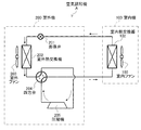
図3は、図1の空気調和機の冷媒サイクルの構成を示した図である。なお、説明を容易にするため、室内機100における、室内熱交換器102および室内ファン103以外の構成は図示を省略している。室外機200は、圧縮機205と、四方弁204と、室外熱交換器202と、室外ファン203と、膨張弁201とを備える。室外機200の圧縮機205で圧縮されて高温高圧となったガス冷媒は、四方弁204を介して、凝縮器として機能する室内熱交換器102に流入する。室内熱交換器102を通流する高温高圧のガス冷媒は、室内ファン103により送られてくる室内空気と熱交換し、凝縮する。
FIG. 3 is a diagram showing the configuration of the refrigerant cycle of the air conditioner of FIG. For ease of explanation, the configuration of the
室内熱交換器102から流出した中温高圧の液冷媒は、膨張弁201で減圧され、低温低圧の気液二相冷媒となり、蒸発器として機能する室外熱交換器202に流入する。室外熱交換器202を通流する気液二相冷媒は、室外ファン203により送られてくる室外空気と熱交換して蒸発し、低温低圧のガス冷媒(または、若干の液冷媒を含む湿りガス冷媒)となる。室外熱交換器202から流入する低温低圧のガス冷媒は、四方弁204を介して圧縮機205に還流する。
The medium-temperature and high-pressure liquid refrigerant that has flowed out of the
図4は、図1の空気調和機の機能ブロック図である。図4において、室内機100における、前面パネル106、上下風向板105、運転ランプ122、予熱ランプ121、人体検出センサ110、室内温度計123、室内ファン103、室内機マイコン130、タイマー150以外の構成は図示を省略している。また、室外機200における室外ファン203、圧縮機205、室外温度計206以外の構成は図示を省略している。
FIG. 4 is a functional block diagram of the air conditioner of FIG. In FIG. 4, the configuration of the
図4に示すように空気調和機Aは、前面パネル106、上下風向板105、運転ランプ122、予熱ランプ121、人体検出センサ110、室内温度計123、室内ファン103、室内機マイコン(制御手段)130およびタイマー150を備える。室内温度計123は室温を室内機マイコン130に出力する。室内機マイコン130は、空気調和機A全体の制御を司り、駆動制御部131、人体検出部132および温度判断部133を備える。また、室内機マイコン130の備える記憶部(図示省略)の所定領域に、設定時刻(タイマー設定時刻)を記憶する。設定時刻は、リモコンReからの操作により入力される低能力予熱(詳細は後記)開始の時刻を算出するための基準の時刻である。
As shown in FIG. 4, the air conditioner A includes a
駆動制御部131は、リモコンReからのリモコン信号や、人体検出部132による人体検出結果、温度判断部133による温度判断結果に基づき、室内機100の前面パネル106、上下風向板105、運転ランプ122、予熱ランプ121および室内ファン103と、室外機200の室外ファン203および圧縮機205とを制御し、低能力予熱(第1の予熱)や、高能力予熱(第2の予熱)や、通常暖房への運転切り替えを行う。低能力予熱、高能力予熱、通常暖房の詳細は後記する。
The
人体検出部132は、人体検出センサ110から、人体検出信号を受信すると、この信号を駆動制御部131へ出力する。また、温度判断部133は、室内温度計123からの室温測定結果および室外温度計206からの外気温測定結果を受信すると、その結果に基づき、低能力予熱を開始するか否かの判断を行う。例えば、温度判断部133は、外気温10℃以上または室温18℃以上ならば予熱運転を行わないと判断する。
When the human
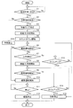
次に、図5および図6を用いて空気調和機Aの室内機マイコン130の処理手順を説明する。まず、図5を用いて、室内機マイコン130の処理の概要を説明する。図5は、図1の室内機の処理手順を示した図である。図6は、図1の室内機マイコンの処理手順の具体例を示したタイムチャートである。ここでは既に利用者がリモコンRe等により空気調和機Aがタイマー設定時刻(設定時刻)の入力を受け付け、室内マイコン130の所定領域に記憶されているものとする。また、空気調和機Aは、このタイマー設定時刻の所定時間前(ここでは60分前)になると低能力予熱を開始するものとする。 Next, the processing procedure of the indoor unit microcomputer 130 of the air conditioner A will be described with reference to FIGS. 5 and 6. First, the outline of the processing of the indoor unit microcomputer 130 will be described with reference to FIG. FIG. 5 is a diagram showing a processing procedure of the indoor unit of FIG. FIG. 6 is a time chart showing a specific example of the processing procedure of the indoor unit microcomputer of FIG. Here, it is assumed that the user has already received the input of the timer set time (set time) by the remote controller Re or the like and has stored it in a predetermined area of the indoor microcomputer 130. In addition, the air conditioner A starts low-capacity preheating when a predetermined time (60 minutes before) of the timer setting time comes.
まず、室内機マイコン130は、タイマー設定時刻と、タイマー150の示す現在時刻とを参照して、現在時刻が(設定時刻―60分)になったと判断すると(S1のYes)、温度判断部133は、室内温度計123から取得した室温および室外温度計206から取得した室外温度をもとに、予熱温度条件を満たすか否かを判断する(S2)。一方、まだ現在時刻が(設定時刻―60分)になっていない場合(S1のNo)、S1へ戻る。S2の予熱温度条件は、例えば、室温が18℃未満かつ外気温10℃未満ならば予熱運転を行うという条件である。S2において温度判断部133が予熱温度条件を満たすと判断したとき(S2のYes)、駆動制御部131を介して、予熱ランプ121を点灯させる(S3)。そして、S4へ進む。一方、S2において、温度判断部133が、予熱温度条件を満たさないと判断したとき(S2のNo)、駆動制御部131は予熱を禁止する(S16)。つまり、低能力予熱を行わない。そして、処理を終了する。このように、駆動制御部131が、予熱条件を満たさないときに低能力予熱を行わないようにすることで、空気調和機Aの予熱時の消費電力を低減できる。
First, the indoor unit microcomputer 130 refers to the timer set time and the current time indicated by the
S3の後、駆動制御部131は、低能力予熱を開始する(S4)。そして、駆動制御部131は、カウントダウンを開始する(S5)。つまり、駆動制御部131はタイマー150を参照して、タイマー設定時刻から所定時間(例えば、30分)後までのカウントダウンを開始する。そして、駆動制御部131において、リモコンReからの暖房運転開始のリモコン信号等、暖房運転開始の信号の入力を受け付けると(S6のYes)、駆動制御部131は暖房運転を開始する(S10)。具体的には、駆動制御部131は、通常暖房(詳細は後記)に移行する。
After S3, the
一方、駆動制御部131に暖房運転開始の信号が未入力の場合(S6のNo)、人体検出部132は、人体検出センサ110から人体検出信号の入力があるか否かを判断する(S7)。ここで、人体検出センサ110から人体検出信号の入力があった場合(S7のYes)、駆動制御部131は、圧縮機205を動作させて高能力予熱(詳細は後記)を開始する(S8)。そして、S9へ進む。
On the other hand, when the heating operation start signal is not input to the drive control unit 131 (No in S6), the human
一方、S6の後、人体検出部132は、人体検出センサ110からの人検出の信号の入力がない場合(S7のNo)、駆動制御部131は、タイマー150を参照して、S5のカウントダウン開始からタイムアップしている(タイマー設定時刻から所定時間(例えば、30分)経過している)か否かを判断する(S13)。ここでタイムアップしていなければ(S13のNo)、S6へ戻る。一方、タイムアップしていれば(S13のYes)、駆動制御部131は予熱(S4で開始した低能力予熱)を停止する(S15)。そして、駆動制御部131は、予熱ランプ121を消灯し、処理を終了する。つまり、タイマー設定時刻から所定時間経過しても、室内に人が入ってこなかった場合、および、タイマー設定時刻から所定時間経過してしまった場合、駆動制御部131は、低能力予熱を停止する。これにより、空気調和機Aの低能力予熱時の消費電力を低減できる。
On the other hand, after S6, when no human detection signal is input from the human body detection sensor 110 (No in S7), the human
S9において、駆動制御部131は、リモコンReからの暖房運転開始のリモコン信号等、暖房運転開始の信号の入力を受け付けると(S9のYes)、暖房運転を開始する(S10)。また、駆動制御部131は運転ランプ122を点灯させる。そして、S11へ進む。一方、S9において、駆動制御部131は、駆動制御部131は、暖房運転開始の信号の入力を受け付けなかったとき(S9のNo)、S5のカウントダウン開始からタイムアップしている(タイマー設定時刻から所定時間(例えば、30分)経過している)か否かを判断し(S14)、タイムアップしていなければ(S14のNo)、S9へ戻る。一方、タイムアップしていれば(S14のYes)、駆動制御部131は予熱を停止する(S15)。そして、駆動制御部131は、予熱ランプ121を消灯し、処理を終了する。つまり、室内に人が入って来たが、結局、暖房運転の指示がされなかった場合、駆動制御部131は、高能力予熱を停止する。これにより、空気調和機Aの高能力予熱時の消費電力を低減できる。
In S9, when the
S11において、駆動制御部131は、リモコンReからの暖房停止のリモコン信号等、暖房停止の信号の入力を受け付けると(S11のYes)、暖房運転を停止する(S12)。そして、駆動制御部131は、運転ランプ122を消灯し、処理を終了する。一方、駆動制御部131は、リモコンReからの暖房停止のリモコン信号等、暖房停止の信号の入力がない場合(S11のNo)、S11へ戻る。
In S11, when the
次に、図5を参照しつつ図6を用いて、図4の空気調和機Aの室内機マイコン130の処理手順の例を説明する。なお、このタイムチャートの横軸は時間の流れを示す。また、ここでも、予熱期間の開始時刻はタイマー設定時刻の60分前からであり、この予熱期間の終了時刻は、最大でタイマー設定時刻+30分までである場合を例に説明する。 Next, an example of the processing procedure of the indoor unit microcomputer 130 of the air conditioner A of FIG. 4 will be described using FIG. 6 with reference to FIG. The horizontal axis of this time chart shows the flow of time. Here, the start time of the preheating period is from 60 minutes before the timer setting time, and the end time of the preheating period is described as an example up to the timer setting time +30 minutes.
室内機マイコン130の駆動制御部131は、タイマー150を参照して、設定時刻(タイマー設定時刻)の60分前になったことを検知し(図5のS1のYes)、温度判断部133により予熱温度条件を満たすことを確認すると(S2のYes)、予熱ランプ121を点灯させる(S3)。なお、この段階では、前面パネル106も上下風向板105もシャット(閉じた状態)のままとする。
The
そして、駆動制御部131は、低能力予熱を開始する(S4)。具体的には、駆動制御部131は、まず圧縮機205を始動させ、予め設定された低能力予熱の回転数(例えば、図6に示す予熱下限1の回転数〜予熱上限1の回転数)で回転させる。また、駆動制御部131は、室内ファン103を予熱専用回転数で回転させる。さらに、駆動制御部131は、室外ファン203の回転数を予熱専用回転数で回転させる。
Then, the
そして、駆動制御部131、タイマー150およびタイマー設定時刻を参照しながら、タイマー設定時刻+30分までのカウントダウンを開始する(S5)。そして、設定時刻+30分までの間に、人体検出部132が人を検出すると(S6のYes→S7のYes)、駆動制御部131は高能力予熱を開始する(S8)。つまり、駆動制御部131は、圧縮機205の回転数を高能力予熱の回転数まで上昇させる。例えば、駆動制御部131は、圧縮機205の回転数を、図6に示す予熱上限2の回転数まで上昇させる。なお、このときの圧縮機205の回転数の下限値は、例えば、図6に示す予熱下限の値とする。
Then, the countdown to the timer set time + 30 minutes is started with reference to the
その後、駆動制御部131はリモコンReから暖房運転開始の信号の入力を受け付けると(S9のYes)、暖房運転を開始する(S10)。駆動制御部131は、まず、前面パネル106をオープンの状態にし、また、駆動制御部131は運転ランプ122を点灯させ、
Thereafter, when the
上下風向板105を暖房イニシャル位置(通常暖房のときの位置)まで移動させ、圧縮機205の回転数を通常暖房の回転数(図6に示すMAX回転数〜暖房の下限)で回転させる。また、駆動制御部131は、室内ファン103については通常制御とし、室外ファン203については通常制御とする。
The vertical
なお、前記したとおり、駆動制御部131がリモコンReにより運転停止信号が入力されると、運転を停止させる。また、駆動制御部131は、タイマー設定時間から30分経過しても、つまり、延長運転時間が経過しても、リモコンReによる運転開始信号が入力されなかったとき、予熱(低能力予熱または高能力予熱)を停止する。
As described above, when the
このようにすることで、空気調和機Aは、低能力予熱を開始後、室内に利用者(人体)が居ることを検出してから高能力予熱を開始する。よって、空気調和機Aが暖房運転開始時に高温風を短時間で吹き出せるようにしつつ、予熱運転中の消費電力を低減することができる。 By doing in this way, the air conditioner A starts high-capacity preheating after detecting that there is a user (human body) in the room after starting low-capacity preheating. Therefore, the power consumption during the preheating operation can be reduced while allowing the air conditioner A to blow out the high-temperature air in a short time when the heating operation is started.
なお、室内機100が室内に人体がいることを確実に検知できるよう、室内機100の人体検出センサ110として、カメラおよび明るさセンサ(図示省略)を用いるようにしてもよい。この場合、カメラが室内に人体がいることを検出しやすくするため、レンズ部分の首振り機能を備えていてもよい。そして、駆動制御部131は、明るさセンサにより、室内が所定の明るさ以上になったことを検知すると、カメラの首振り機能を動作させ、カメラによる撮像を開始させる。その後、人体検出部132はカメラからの画像により室内に人体がいると判断すると、駆動制御部131は、前記した高能力予熱を開始する。なお、駆動制御部131は、人体検出部132において室内に人体がいると判断されたとき、カメラの首振りを停止させる。このように、人体検出センサ110に首振り機能付きのカメラを用いる場合、明るさセンサを併用することで、室内に人体がいる可能性が高いときにカメラの首振りを行わせることができる。また、明るさをカメラの画像から検出することで明るさセンサを搭載することなく同様の機能を実現することができる。
Note that a camera and a brightness sensor (not shown) may be used as the human
100 室内機
101 筐体ベース
102 室内熱交換器
102a 伝熱管
103 室内ファン
104 左右風向板
105 上下風向板
106 前面パネル
107 空気吸込み口
108 フィルタ
109a 吹出し風路
109b 空気吹出し口
110 人体検出センサ
121 予熱ランプ
122 運転ランプ
123 室内温度計
130 室内機マイコン(制御手段)
131 駆動制御部
132 人体検出部
133 温度判断部
150 タイマー
200 室外機
201 膨張弁
202 室外熱交換器
203 室外ファン
204 四方弁
205 圧縮機
206 室外温度計
A 空気調和機
Q リモコン受信部
Re リモコン
DESCRIPTION OF
131
Claims (6)
室内温度を検出する室内温度検出部と、
外気温度を検出する外気温度検出部と、
利用者により予め入力されたタイマー設定時刻の第1の所定時間前から空気調和機の圧縮機の第1の予熱運転を実行し、前記タイマー設定時刻後の第2の所定時間が経過するまでの間に、前記人体検出部が人体を検出したとき、前記第1の予熱運転より前記圧縮機の回転数が高く、かつ、通常暖房運転の上限より前記圧縮機の回転数が低い範囲で第2の予熱運転を実行し、リモコンから暖房運転開始の指示信号が入力されると前記通常暖房運転に入る駆動制御部とを備え、
前記駆動制御部は、前記タイマー設定時刻の前記第1の所定時間前において、前記室内温度検出部が検出した室内温度が室内の所定値未満であり、かつ、前記外気温度検出部が検出した外気温度が外気の所定値未満であるとき、前記第1の予熱運転を開始する
ことを特徴とする空気調和機。 A human body detection unit for detecting a human body in the room;
An indoor temperature detector for detecting the indoor temperature;
An outside temperature detector for detecting the outside temperature;
Before a first predetermined pre-inputted timer set time by the user time to perform the first pre-heating operation of the compressor of an air conditioner, to a second predetermined time after the timer set time elapses During this time, when the human body detecting unit detects a human body, the number of rotations of the compressor is higher than that of the first preheating operation and is lower than the upper limit of normal heating operation. A drive control unit that performs the preheating operation of No. 2 and enters the normal heating operation when an instruction signal for starting the heating operation is input from a remote controller,
The drive control unit is configured such that the room temperature detected by the room temperature detection unit is less than a predetermined value in the room and the outside air detected by the outside air temperature detection unit before the first predetermined time before the timer set time. When the temperature is lower than a predetermined value of the outside air, the first preheating operation is started.
前記第1の予熱運転の実行を始めた後、前記タイマー設定時刻後の前記第2の所定時間経過するまでの間に前記人体検出部が人体を検出しなかったとき、および、前記タイマー設定時刻後の前記第2の所定時間が経過したとき、前記第1の予熱運転を停止する
ことを特徴とする請求項1に記載の空気調和機。 The drive control unit
After starting the execution of the first preheating operation, when the human body detection unit until elapsed the timer set time the second predetermined time after does not detect a human body, and the timer setting time The air conditioner according to claim 1, wherein the first preheating operation is stopped when the second predetermined time later elapses.
前記第2の予熱運転の実行を始めた後、前記第2の所定時間経過するまでの間に暖房運転開始の指示信号が入力されなかったとき、および、前記第2の予熱運転の実行を始めた後、前記第2の所定時間が経過したとき、前記第2の予熱運転を停止する
ことを特徴とする請求項1または請求項2に記載の空気調和機。 The drive control unit
After the execution of the second preheating operation is started, when the instruction signal for starting the heating operation is not input before the second predetermined time elapses, and the execution of the second preheating operation is started. 3. The air conditioner according to claim 1, wherein when the second predetermined time has elapsed, the second preheating operation is stopped.
前記室内を撮像するカメラおよび前記室内の明るさを検出する明るさセンサを有し、
前記駆動制御部は、
前記明るさセンサが所定値以上の明るさを検知すると、前記カメラの首振り機能を動作させ、前記カメラによる撮像を開始させる
ことを特徴とする請求項1に記載の空気調和機。 The human body detection unit is
A camera that images the room and a brightness sensor that detects the brightness of the room;
The drive control unit
2. The air conditioner according to claim 1, wherein when the brightness sensor detects a brightness of a predetermined value or more, the camera swing function is activated to start imaging by the camera.
前記室内を撮像するカメラを有し、
前記駆動制御部は、
前記カメラが所定値以上の明るさを検知すると、前記カメラの首振り機能を動作させ、前記カメラによる撮像を開始させる
ことを特徴とする請求項1に記載の空気調和機。 The human body detection unit is
A camera for imaging the room;
The drive control unit
2. The air conditioner according to claim 1, wherein when the camera detects brightness of a predetermined value or more, the camera swing function is activated to start imaging by the camera.
利用者により予め入力されたタイマー設定時刻の第1の所定時間前から空気調和機の圧縮機の予熱運転を実行した後、前記タイマー設定時刻後の第2の所定時間が経過するまでの間に、前記人体検出部が人体を検出したとき、前記圧縮機の回転数を通常暖房運転の上限より低い範囲で上昇させ、リモコンから暖房運転開始の指示信号が入力されると前記通常暖房運転に入る空気調和機の制御方法であって、
前記タイマー設定時刻の前記第1の所定時間前において、前記室内温度検出部が検出した室内温度が室内の所定値未満であり、かつ、前記外気温度検出部が検出した外気温度が外気の所定値未満であるとき、前記予熱運転を開始する
ことを特徴とする空気調和機の制御方法。 An air conditioner including a human body detection unit that detects a human body in a room, an indoor temperature detection unit that detects a room temperature, and an outside air temperature detection unit that detects an outside air temperature,
Between before user by a first predetermined time previously entered timer set time after performing the preheating operation of the air conditioner compressor, to a second predetermined time after the timer set time elapses In addition, when the human body detecting unit detects a human body, the rotation speed of the compressor is increased in a range lower than the upper limit of the normal heating operation , and when the instruction signal for starting the heating operation is input from the remote controller, the normal heating operation is performed. An air conditioner control method for entering,
The indoor temperature detected by the indoor temperature detection unit is less than a predetermined value in the room before the first predetermined time before the timer set time, and the outside temperature detected by the outside temperature detection unit is a predetermined value of the outside air When it is less than the above, the preheating operation is started.
Priority Applications (3)
| Application Number | Priority Date | Filing Date | Title |
|---|---|---|---|
| JP2012191591A JP6116087B2 (en) | 2012-08-31 | 2012-08-31 | Air conditioner and control method of air conditioner |
| KR1020130093128A KR101624385B1 (en) | 2012-08-31 | 2013-08-06 | Air conditioner and control method of air conditioner |
| CN201310344222.0A CN103673210B (en) | 2012-08-31 | 2013-08-08 | Air conditioner and the control method of air conditioner |
Applications Claiming Priority (1)
| Application Number | Priority Date | Filing Date | Title |
|---|---|---|---|
| JP2012191591A JP6116087B2 (en) | 2012-08-31 | 2012-08-31 | Air conditioner and control method of air conditioner |
Publications (3)
| Publication Number | Publication Date |
|---|---|
| JP2014047982A JP2014047982A (en) | 2014-03-17 |
| JP2014047982A5 JP2014047982A5 (en) | 2014-10-16 |
| JP6116087B2 true JP6116087B2 (en) | 2017-04-19 |
Family
ID=50311524
Family Applications (1)
| Application Number | Title | Priority Date | Filing Date |
|---|---|---|---|
| JP2012191591A Active JP6116087B2 (en) | 2012-08-31 | 2012-08-31 | Air conditioner and control method of air conditioner |
Country Status (3)
| Country | Link |
|---|---|
| JP (1) | JP6116087B2 (en) |
| KR (1) | KR101624385B1 (en) |
| CN (1) | CN103673210B (en) |
Families Citing this family (11)
| Publication number | Priority date | Publication date | Assignee | Title |
|---|---|---|---|---|
| CN104197464A (en) * | 2014-07-28 | 2014-12-10 | 珠海格力电器股份有限公司 | Method and system for controlling heating of air conditioner |
| JP2016114345A (en) * | 2014-12-12 | 2016-06-23 | 東芝キヤリア株式会社 | Air conditioner |
| CN205980413U (en) * | 2015-04-20 | 2017-02-22 | 三菱电机株式会社 | Refrigerating cycle device |
| JP6474356B2 (en) * | 2016-01-21 | 2019-02-27 | ファナック株式会社 | Management system that provides optimal warm-up start times for multiple machines |
| JP6624219B2 (en) * | 2018-02-23 | 2019-12-25 | ダイキン工業株式会社 | Air conditioner |
| JP6956862B2 (en) * | 2018-04-20 | 2021-11-02 | 三菱電機株式会社 | Air conditioner |
| JP2019190768A (en) * | 2018-04-26 | 2019-10-31 | 三菱電機株式会社 | Environment control system |
| CN109186038B (en) * | 2018-08-15 | 2019-11-12 | 珠海格力电器股份有限公司 | A kind of control method of air-conditioning, device, storage medium and air-conditioning |
| CN110274364A (en) * | 2019-06-28 | 2019-09-24 | 宁波奥克斯电气股份有限公司 | A kind of control method, system and the air-conditioning of air conditioner intelligent air-supply |
| CN114502893A (en) * | 2020-03-16 | 2022-05-13 | 日立江森自控空调有限公司 | Air conditioner |
| CN113531802B (en) * | 2021-06-22 | 2022-10-28 | 青岛海尔空调器有限总公司 | Method for preheating air conditioner, air conditioner and air conditioning system |
Family Cites Families (7)
| Publication number | Priority date | Publication date | Assignee | Title |
|---|---|---|---|---|
| JPS61128056A (en) * | 1984-11-28 | 1986-06-16 | Toshiba Corp | Air conditioner |
| JP2000047293A (en) * | 1998-07-30 | 2000-02-18 | Yokogawa Electric Corp | Pan and tilt camera apparatus |
| JP2005106355A (en) * | 2003-09-30 | 2005-04-21 | Fujitsu General Ltd | Control method for air conditioner |
| JP4736955B2 (en) * | 2006-05-29 | 2011-07-27 | パナソニック電工株式会社 | Sensor camera |
| JP5448390B2 (en) * | 2008-08-22 | 2014-03-19 | 東芝キヤリア株式会社 | Air conditioner |
| JP5127871B2 (en) * | 2010-04-09 | 2013-01-23 | 三菱電機株式会社 | Air conditioning system |
| JP5300793B2 (en) * | 2010-06-11 | 2013-09-25 | 三菱電機株式会社 | Air conditioner |
-
2012
- 2012-08-31 JP JP2012191591A patent/JP6116087B2/en active Active
-
2013
- 2013-08-06 KR KR1020130093128A patent/KR101624385B1/en active IP Right Grant
- 2013-08-08 CN CN201310344222.0A patent/CN103673210B/en active Active
Also Published As
| Publication number | Publication date |
|---|---|
| KR101624385B1 (en) | 2016-05-25 |
| KR20140029177A (en) | 2014-03-10 |
| CN103673210A (en) | 2014-03-26 |
| JP2014047982A (en) | 2014-03-17 |
| CN103673210B (en) | 2016-09-28 |
Similar Documents
| Publication | Publication Date | Title |
|---|---|---|
| JP6116087B2 (en) | Air conditioner and control method of air conditioner | |
| CN104236027B (en) | Air conditioner | |
| KR20090085368A (en) | Air conditioner and controlling method thereof | |
| CN107305035B (en) | Air conditioner | |
| JP2019060561A (en) | Air conditioner | |
| JP2020193759A (en) | Air conditioning system | |
| CN105518396A (en) | Air conditioning system | |
| KR20110001667A (en) | Air conditioner and operating method thereof | |
| JP2011153725A (en) | Ceiling-mounted type indoor unit of air conditioning device | |
| JPH1183113A (en) | Air conditioner | |
| JP7420562B2 (en) | Air conditioners and servers | |
| JP6557101B2 (en) | Air conditioner | |
| US20170102157A1 (en) | Air conditioner units and methods for determining indoor room temperatures | |
| TW571057B (en) | Air conditioner | |
| JP2006112696A (en) | Air conditioner | |
| JP2001021191A (en) | Controller for air conditioner | |
| JP5598392B2 (en) | Air conditioner | |
| WO2018029872A1 (en) | Air conditioner | |
| JP6059769B2 (en) | Air conditioner | |
| JP2019109025A (en) | Air conditioner | |
| JP6833092B1 (en) | Air conditioner | |
| WO2021186498A1 (en) | Air conditioner | |
| JP2001041553A (en) | Air conditioner | |
| JP7199594B2 (en) | Air conditioner and method for discharging air from air conditioner | |
| JP7139813B2 (en) | air conditioner |
Legal Events
| Date | Code | Title | Description |
|---|---|---|---|
| A521 | Written amendment |
Free format text: JAPANESE INTERMEDIATE CODE: A523 Effective date: 20140829 |
|
| A621 | Written request for application examination |
Free format text: JAPANESE INTERMEDIATE CODE: A621 Effective date: 20140829 |
|
| A977 | Report on retrieval |
Free format text: JAPANESE INTERMEDIATE CODE: A971007 Effective date: 20150119 |
|
| A131 | Notification of reasons for refusal |
Free format text: JAPANESE INTERMEDIATE CODE: A131 Effective date: 20150224 |
|
| A521 | Written amendment |
Free format text: JAPANESE INTERMEDIATE CODE: A523 Effective date: 20150406 |
|
| A02 | Decision of refusal |
Free format text: JAPANESE INTERMEDIATE CODE: A02 Effective date: 20150929 |
|
| A521 | Written amendment |
Free format text: JAPANESE INTERMEDIATE CODE: A523 Effective date: 20151222 |
|
| A521 | Written amendment |
Free format text: JAPANESE INTERMEDIATE CODE: A821 Effective date: 20151225 |
|
| A911 | Transfer of reconsideration by examiner before appeal (zenchi) |
Free format text: JAPANESE INTERMEDIATE CODE: A911 Effective date: 20160121 |
|
| A912 | Removal of reconsideration by examiner before appeal (zenchi) |
Free format text: JAPANESE INTERMEDIATE CODE: A912 Effective date: 20160401 |
|
| A711 | Notification of change in applicant |
Free format text: JAPANESE INTERMEDIATE CODE: A711 Effective date: 20160407 |
|
| A521 | Written amendment |
Free format text: JAPANESE INTERMEDIATE CODE: A523 Effective date: 20161128 |
|
| A521 | Written amendment |
Free format text: JAPANESE INTERMEDIATE CODE: A523 Effective date: 20170116 |
|
| A61 | First payment of annual fees (during grant procedure) |
Free format text: JAPANESE INTERMEDIATE CODE: A61 Effective date: 20170320 |
|
| R150 | Certificate of patent or registration of utility model |
Ref document number: 6116087 Country of ref document: JP Free format text: JAPANESE INTERMEDIATE CODE: R150 |
|
| S111 | Request for change of ownership or part of ownership |
Free format text: JAPANESE INTERMEDIATE CODE: R313113 |
|
| R360 | Written notification for declining of transfer of rights |
Free format text: JAPANESE INTERMEDIATE CODE: R360 |
|
| R360 | Written notification for declining of transfer of rights |
Free format text: JAPANESE INTERMEDIATE CODE: R360 |
|
| R371 | Transfer withdrawn |
Free format text: JAPANESE INTERMEDIATE CODE: R371 |
|
| S111 | Request for change of ownership or part of ownership |
Free format text: JAPANESE INTERMEDIATE CODE: R313113 |
|
| R350 | Written notification of registration of transfer |
Free format text: JAPANESE INTERMEDIATE CODE: R350 |
|
| R250 | Receipt of annual fees |
Free format text: JAPANESE INTERMEDIATE CODE: R250 |