JP6112463B2 - Frequency control method, frequency control apparatus and system - Google Patents
Frequency control method, frequency control apparatus and system Download PDFInfo
- Publication number
- JP6112463B2 JP6112463B2 JP2015110035A JP2015110035A JP6112463B2 JP 6112463 B2 JP6112463 B2 JP 6112463B2 JP 2015110035 A JP2015110035 A JP 2015110035A JP 2015110035 A JP2015110035 A JP 2015110035A JP 6112463 B2 JP6112463 B2 JP 6112463B2
- Authority
- JP
- Japan
- Prior art keywords
- power
- frequency
- discharge
- charge
- power storage
- Prior art date
- Legal status (The legal status is an assumption and is not a legal conclusion. Google has not performed a legal analysis and makes no representation as to the accuracy of the status listed.)
- Expired - Fee Related
Links
Images
Classifications
-
- H—ELECTRICITY
- H02—GENERATION; CONVERSION OR DISTRIBUTION OF ELECTRIC POWER
- H02J—CIRCUIT ARRANGEMENTS OR SYSTEMS FOR SUPPLYING OR DISTRIBUTING ELECTRIC POWER; SYSTEMS FOR STORING ELECTRIC ENERGY
- H02J3/00—Circuit arrangements for ac mains or ac distribution networks
- H02J3/28—Arrangements for balancing of the load in a network by storage of energy
- H02J3/32—Arrangements for balancing of the load in a network by storage of energy using batteries with converting means
-
- H—ELECTRICITY
- H02—GENERATION; CONVERSION OR DISTRIBUTION OF ELECTRIC POWER
- H02J—CIRCUIT ARRANGEMENTS OR SYSTEMS FOR SUPPLYING OR DISTRIBUTING ELECTRIC POWER; SYSTEMS FOR STORING ELECTRIC ENERGY
- H02J3/00—Circuit arrangements for ac mains or ac distribution networks
- H02J3/24—Arrangements for preventing or reducing oscillations of power in networks
- H02J3/241—The oscillation concerning frequency
-
- H—ELECTRICITY
- H01—ELECTRIC ELEMENTS
- H01L—SEMICONDUCTOR DEVICES NOT COVERED BY CLASS H10
- H01L2224/00—Indexing scheme for arrangements for connecting or disconnecting semiconductor or solid-state bodies and methods related thereto as covered by H01L24/00
- H01L2224/01—Means for bonding being attached to, or being formed on, the surface to be connected, e.g. chip-to-package, die-attach, "first-level" interconnects; Manufacturing methods related thereto
- H01L2224/10—Bump connectors; Manufacturing methods related thereto
- H01L2224/12—Structure, shape, material or disposition of the bump connectors prior to the connecting process
- H01L2224/14—Structure, shape, material or disposition of the bump connectors prior to the connecting process of a plurality of bump connectors
Landscapes
- Engineering & Computer Science (AREA)
- Power Engineering (AREA)
- Supply And Distribution Of Alternating Current (AREA)
Description
本開示は、電力系統の周波数を基準周波数へ近づけるための制御を行う周波数制御方法、周波数制御装置、システム、および蓄電装置に関する。 The present disclosure relates to a frequency control method, a frequency control device, a system, and a power storage device that perform control for bringing the frequency of a power system closer to a reference frequency.
従来、電力系統の周波数が基準周波数を維持するように、電力系統に接続された蓄電池システムに電力を充電し、又は、蓄電池システムから電力を放電する充放電制御を行う技術が開示されている(特許文献1参照)。 DESCRIPTION OF RELATED ART Conventionally, the technique which performs charge / discharge control which charges electric power to the storage battery system connected to the electric power system, or discharges electric power from the storage battery system so that the frequency of an electric power system maintains a reference | standard frequency ( Patent Document 1).
しかしながら、特許文献1の周波数制御方式では、複数の蓄電池を備える場合にシステム全体の総合的な効率が十分ではない。そこで、本開示は、複数の蓄電装置を備えるシステムにおいて総合的な効率を向上させる周波数制御方法、周波数制御装置、システムおよび蓄電装置を提供する。
However, in the frequency control system of
本開示の一態様に係る周波数制御方法は、分散配置された複数の蓄電装置と周波数制御装置とを有するシステムにおいて、前記複数の蓄電装置の充放電制御を行うことによって電力系統の周波数を制御する、あるいは需給バランスを維持する周波数制御方法であって、前記周波数制御装置において、予め定められた基準周波数から、予め定められた下限周波数または予め定められた上限周波数までの区間を前記複数の蓄電装置の台数に応じて複数の周波数範囲に分割する分割ステップと、前記電力系統の現在の周波数を検出する検出ステップと、前記複数の周波数範囲のうち、前記現在の周波数が属する周波数範囲が前記基準周波数から離れた周波数範囲であるほど、前記電力系統に放電するまたは前記電力系統から供給される電力を充電する蓄電装置の台数が増加するように前記複数の蓄電装置を制御する制御ステップとを有し、前記複数の周波数範囲は、前記基準周波数との差分の絶対値が0以上で第1の値より小さい第1の周波数範囲と、前記基準周波数との差分の絶対値が前記第1の値以上で第2の値より小さい第2の周波数範囲とを含み、前記周波数制御方法は、さらに、前記複数の蓄電装置の劣化度、残存容量、および使用頻度の少なくとも1つに応じて、前記複数の蓄電装置の中から、前記複数の周波数範囲のすべての周波数範囲で放電または充電させる第1の蓄電装置を選択し、前記第1の周波数範囲以外の周波数範囲で放電または充電させる第2の蓄電装置を選択する選択ステップを有し、前記制御ステップにおいて、前記電力系統の実際の周波数が前記第1の周波数範囲内にある場合に、前記第1の蓄電装置から前記電力系統に放電させ、かつ前記第2の蓄電装置から前記電力系統に放電させないように制御し、または、前記電力系統から前記第1の蓄電装置に充電させ、かつ前記電力系統から前記第2の蓄電装置に充電させないように制御し、前記第1の蓄電装置は、前記複数の周波数範囲のそれぞれにおいて、前記基準周波数に対する前記現在の周波数の偏差が大きいほど前記第1の蓄電装置から前記電力系統への放電電力を増加させ、または、前記電力系統から前記第1の蓄電装置への充電電力を増加させ、前記第1の蓄電装置において、前記第1の周波数範囲における前記放電電力または前記充電電力の前記偏差に対する増加率が、他のいずれの周波数範囲における前記放電電力または前記充電電力の前記偏差に対する増加率よりも大きく、前記第1の周波数範囲において、前記第1の蓄電装置から前記電力系統への前記放電電力は、前記偏差に応じて0から第1の放電電力まで増加し、前記電力系統から前記第1の蓄電装置への前記充電電力は、0から第1の充電電力まで前記偏差に応じて増加し、前記第2の周波数範囲において、前記第1の蓄電装置から前記電力系統への前記放電電力は、前記第1の放電電力より小さい第2の放電電力から第3の放電電力まで前記偏差に応じて増加し、前記電力系統から前記第1の蓄電装置に充電される前記充電電力は、前記第1の充電電力より小さい第2の充電電力から第3の充電電力まで前記偏差に応じて増加し、 前記周波数制御装置は、前記第2の周波数範囲において、前記第1の蓄電装置から前記電力系統への前記放電電力の増加率と前記第2の蓄電装置から前記電力系統への放電電力の増加率とを一致させ、前記電力系統から前記第1の蓄電装置への前記充電電力の増加率と前記電力系統から前記第2の蓄電装置への充電電力の増加率とを一致させる。 A frequency control method according to an aspect of the present disclosure controls a frequency of an electric power system by performing charge / discharge control of the plurality of power storage devices in a system including a plurality of power storage devices and frequency control devices that are arranged in a distributed manner. Or a frequency control method for maintaining a supply and demand balance, wherein in the frequency control device, the plurality of power storage devices are defined as a section from a predetermined reference frequency to a predetermined lower limit frequency or a predetermined upper limit frequency. A division step of dividing the frequency range into a plurality of frequency ranges according to the number of the power supply, a detection step of detecting a current frequency of the power system, and a frequency range to which the current frequency belongs among the plurality of frequency ranges is the reference frequency The farther away the frequency range is, the more the electric power is discharged to the electric power system or the electric power supplied from the electric power system is charged. Have a control step for the number of power storage device for controlling the plurality of power storage devices to increase the plurality of frequency ranges, the first value is less than the absolute value of 0 or more of the difference between said reference frequency A first frequency range; and a second frequency range in which an absolute value of a difference between the reference frequency and the reference frequency is greater than or equal to the first value and smaller than a second value. A first power storage device that discharges or charges in all frequency ranges of the plurality of frequency ranges from among the plurality of power storage devices in accordance with at least one of a deterioration degree, a remaining capacity, and a use frequency of the power storage device. Selecting and selecting a second power storage device to be discharged or charged in a frequency range other than the first frequency range, and in the control step, the actual frequency of the power system is the first frequency When in the wave number range, the first power storage device is controlled to discharge to the power system and the second power storage device is not discharged to the power system, or from the power system to the first power system. And the second power storage device is controlled not to be charged from the power system, and the first power storage device is configured to control the current frequency with respect to the reference frequency in each of the plurality of frequency ranges. Increasing the frequency deviation increases the discharge power from the first power storage device to the power system, or increases the charging power from the power system to the first power storage device. The rate of increase of the discharge power or charge power in the first frequency range with respect to the deviation is the discharge power or charge in any other frequency range. In the first frequency range, the discharge power from the first power storage device to the power system is greater than 0 to the first discharge power depending on the deviation. The charging power from the power system to the first power storage device increases according to the deviation from 0 to the first charging power, and the first power storage device in the second frequency range The discharge power from the power system to the power system increases according to the deviation from a second discharge power smaller than the first discharge power to a third discharge power, and from the power system to the first power storage device The charging power to be charged increases according to the deviation from a second charging power smaller than the first charging power to a third charging power, and the frequency control device is The first power storage The rate of increase of the discharged power from the power supply to the power system is matched with the rate of increase of discharge power from the second power storage device to the power system, and the charging from the power system to the first power storage device is performed. The power increase rate is matched with the charge power increase rate from the power system to the second power storage device .
なお、これらの包括的または具体的な態様は、システム、方法、集積回路、コンピュータプログラムまたはコンピュータ読み取り可能なCD−ROMなどの記録媒体で実現されてもよく、システム、方法、集積回路、コンピュータプログラムおよび記録媒体の任意な組み合わせで実現されてもよい。 Note that these comprehensive or specific aspects may be realized by a system, a method, an integrated circuit, a computer program, or a recording medium such as a computer-readable CD-ROM, and the system, method, integrated circuit, and computer program. And any combination of recording media.
複数の蓄電装置を備えるシステムにおいて総合的な効率を向上させることができる。 Overall efficiency can be improved in a system including a plurality of power storage devices.
(本発明の基礎となった知見)
本発明者は、「背景技術」の欄において記載した、並列運転制御方式に関し、以下の問題が生じることを見出した。
(Knowledge that became the basis of the present invention)
The present inventor has found that the following problems occur with respect to the parallel operation control system described in the “Background Art” column.
電力系統の周波数を適正範囲(例えば、基準周波数50Hz±0.2Hz)に維持する制御である周波数制御(FR(Frequency Regulation))が行われている。特許文献1では、電力系統の周波数が、基準周波数を維持するように、周波数制御装置が蓄電池に電力を充電させ、又は、蓄電池から電力を放電させる充放電制御を行う技術が開示されている。
Frequency control (FR (Frequency Regulation)), which is control for maintaining the frequency of the power system in an appropriate range (for example, a reference frequency of 50 Hz ± 0.2 Hz), is performed.
しかしながら、蓄電池システムにおける充放電の効率は、充放電電力に依存して変化することから、複数の蓄電装置を含むシステムにおける総合的な効率を向上させることが望まれる。 However, since the charge / discharge efficiency in the storage battery system changes depending on the charge / discharge power, it is desired to improve the overall efficiency in a system including a plurality of power storage devices.
蓄電池システムの充放電の効率は、主として、蓄電池内のインバータの変換効率と、蓄電池の充放電効率によって定まる(DC/DCコンバータを有する場合は、DC/DCコンバータの効率も考慮される)。インバータは、蓄電池からの直流電力を交流電力に変換して電力系統に放電し、また、電力系統からの交流電力を直流電力に変換して蓄電池を充電する。蓄電池システムの充放電の効率は、例えば、インバータの変換効率と、蓄電池の充放電効率との積によって規定される。 The charging / discharging efficiency of the storage battery system is determined mainly by the conversion efficiency of the inverter in the storage battery and the charging / discharging efficiency of the storage battery (when a DC / DC converter is provided, the efficiency of the DC / DC converter is also considered). The inverter converts DC power from the storage battery into AC power and discharges it to the power system, and converts AC power from the power system into DC power to charge the storage battery. The charging / discharging efficiency of the storage battery system is defined by, for example, the product of the conversion efficiency of the inverter and the charging / discharging efficiency of the storage battery.
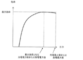
例えば、図7は、実施の形態における蓄電池システムの効率(充放電の効率)の説明図である。横軸は、放電電力または充電電力を示す。縦軸は、効率を示す。同図から、蓄電池システムの効率は、充電最大値または放電最大値の50%以上で高く、充放電電力が小さくなる程極端に低くなる。特許文献1のような周波数制御においては、充電深度のみを考慮して充放電指令値を算出するため、総合的な効率が良いとはいえないという問題がある。そこで、本開示は、複数の蓄電装置を備えるシステムにおいて総合的な効率を向上させる周波数制御方法、周波数制御装置、システムおよび蓄電装置を提供する。
For example, FIG. 7 is an explanatory diagram of the efficiency (charge / discharge efficiency) of the storage battery system in the embodiment. The horizontal axis indicates discharge power or charge power. The vertical axis shows the efficiency. From the figure, the efficiency of the storage battery system is high at 50% or more of the maximum charge value or the maximum discharge value, and becomes extremely low as the charge / discharge power decreases. In frequency control like
このような問題を解決するために、本開示の一態様に係る周波数制御方法は、分散配置された複数の蓄電装置と周波数制御装置とを有するシステムにおいて、前記複数の蓄電装置の充放電制御を行うことによって電力系統の周波数を制御する、あるいは需給バランスを維持する周波数制御方法であって、前記周波数制御装置において、予め定められた基準周波数から、予め定められた下限周波数または予め定められた上限周波数までの区間を前記複数の蓄電装置の台数に応じて複数の周波数範囲に分割する分割ステップと、前記電力系統の現在の周波数を検出する検出ステップと、前記複数の周波数範囲のうち、前記現在の周波数が属する周波数範囲が前記基準周波数から離れた周波数範囲であるほど、前記電力系統に放電するまたは前記電力系統から供給される電力を充電する蓄電装置の台数が増加するように前記複数の蓄電装置を制御する制御ステップとを有する。 In order to solve such a problem, a frequency control method according to an aspect of the present disclosure performs charge / discharge control of the plurality of power storage devices in a system including a plurality of power storage devices and frequency control devices that are distributed. A frequency control method for controlling the frequency of an electric power system by performing or maintaining a supply and demand balance, wherein a predetermined lower limit frequency or a predetermined upper limit is determined from a predetermined reference frequency in the frequency control device. a dividing step of dividing into a plurality of frequency ranges in accordance with section up frequency to the number of said plurality of power storage devices, a detection step of detecting the current frequency of the power system, the plurality of frequency ranges, the current The more the frequency range to which the frequency belongs is the frequency range far from the reference frequency, the more the electric power system discharges or the power And a control step for the number of the power storage device to charge the power supplied from the grid to control the plurality of power storage devices to increase.
これにより、複数の周波数範囲のうち、基準周波数に最も近い(または基準周波数を含む)周波数範囲では、最も少ない台数の蓄電装置が放電または充電し、他の蓄電装置は動作しない。よって、一般的に、効率の良くない小電力の放電または充電を行う蓄電装置の台数を限定するので、複数の蓄電装置を備えるシステムにおいて総合的な効率を向上させることができる。 Thus, in the frequency range closest to the reference frequency (or including the reference frequency) among the plurality of frequency ranges, the smallest number of power storage devices are discharged or charged, and the other power storage devices do not operate. Therefore, in general, the number of power storage devices that perform discharging or charging of inefficient low power is limited, so that overall efficiency can be improved in a system including a plurality of power storage devices.
ここで、前記複数の周波数範囲は、前記基準周波数との差分の絶対値が0以上で第1の値より小さい第1の周波数範囲と、前記基準周波数との差分の絶対値が前記第1の値以上で第2の値より小さい第2の周波数範囲とを含み、前記周波数制御方法は、さらに、前記複数の蓄電装置の劣化度、残存容量、および使用頻度の少なくとも1つに応じて、前記複数の蓄電装置の中から、前記複数の周波数範囲のすべての周波数範囲で放電または充電させる第1の蓄電装置を選択し、前記第1の周波数範囲以外の周波数範囲で放電または充電させる第2の蓄電装置を選択する選択ステップを有し、前記制御ステップにおいて、前記電力系統の実際の周波数が前記第1の周波数範囲内にある場合に、前記第1の蓄電装置から前記電力系統に放電させ、かつ前記第2の蓄電装置から前記電力系統に放電させないように制御し、または、前記電力系統から前記第1の蓄電装置に充電させ、かつ前記電力系統から前記第2の蓄電装置に充電させないように制御してもよい。 Here, the plurality of frequency ranges are such that the absolute value of the difference between the reference frequency and the first frequency range in which the absolute value of the difference from the reference frequency is 0 or more and smaller than the first value is the first frequency range. A second frequency range that is greater than or equal to a second value and less than a second value, and the frequency control method further includes, depending on at least one of the degradation degree, remaining capacity, and usage frequency of the plurality of power storage devices, A first power storage device to be discharged or charged in all frequency ranges of the plurality of frequency ranges is selected from among the plurality of power storage devices, and second to be discharged or charged in a frequency range other than the first frequency range. Selecting a power storage device, and in the control step, when an actual frequency of the power system is within the first frequency range, discharging from the first power storage device to the power system, Or Control so that the second power storage device does not discharge to the power system, or charge the first power storage device from the power system, and do not charge the second power storage device from the power system You may control.
これによれば、偏差が小さい第1の周波数範囲内では、蓄電池のシステム効率が良くないので1台のみ放電させ、他の蓄電装置は使用しない。複数の蓄電池の総合システム効率を向上させることができる。 According to this, in the first frequency range where the deviation is small, since the system efficiency of the storage battery is not good, only one battery is discharged and no other power storage device is used. The overall system efficiency of a plurality of storage batteries can be improved.
ここで、前記第1の蓄電装置は、前記複数の周波数範囲のそれぞれにおいて、前記基準周波数に対する前記現在の周波数の偏差が大きいほど前記第1の蓄電装置から前記電力系統への放電電力を増加させ、または、前記電力系統から前記第1の蓄電装置への充電電力を増加させ、前記第1の蓄電装置において、前記第1の周波数範囲における前記放電電力または前記充電電力の前記偏差に対する増加率が、他のいずれの周波数範囲における前記放電電力または前記充電電力の前記偏差に対する増加率よりも大きくてもよい。 Here, in each of the plurality of frequency ranges, the first power storage device increases the discharge power from the first power storage device to the power system as the deviation of the current frequency with respect to the reference frequency increases. Alternatively, the charging power from the power system to the first power storage device is increased, and in the first power storage device, the rate of increase with respect to the deviation of the discharge power or the charging power in the first frequency range is increased. The increase rate with respect to the deviation of the discharge power or the charge power in any other frequency range may be larger.
これによれば、現在の周波数が基準周波数に近いときに(第1の周波数範囲にあるときに)、第1の蓄電装置の放電を大きくし、他の蓄電装置に放電させないようにすることで、総合効率を向上させることができる。 According to this, when the current frequency is close to the reference frequency (when in the first frequency range), the discharge of the first power storage device is increased so that the other power storage devices do not discharge. , Can improve the overall efficiency.
ここで、前記第1の周波数範囲において、前記第1の蓄電装置から前記電力系統への前記放電電力は、前記偏差に応じて0から第1の放電電力まで増加し、前記電力系統から前記第1の蓄電装置への前記充電電力は、0から第1の充電電力まで前記偏差に応じて増加し、前記第2の周波数範囲において、前記第1の蓄電装置から前記電力系統への放電電力は、前記第1の放電電力より小さい第2の放電電力から第3の放電電力まで前記偏差に応じて増加し、前記電力系統から前記第1の蓄電装置に充電される前記充電電力は、前記第1の充電電力より小さい第2の充電電力から第3の充電電力まで前記偏差に応じて増加してもよい。 Here, in the first frequency range, the discharge power from the first power storage device to the power system increases from 0 to the first discharge power according to the deviation, and from the power system to the first The charging power to one power storage device increases from 0 to the first charging power according to the deviation, and in the second frequency range, the discharging power from the first power storage device to the power system is The charging power that increases from the second discharging power smaller than the first discharging power to the third discharging power according to the deviation and is charged from the power system to the first power storage device is the first discharging power. You may increase according to the said deviation from 2nd charge power smaller than 1 charge power to 3rd charge power.
これによれば、現在の周波数が基準周波数から遠い時に(第2の周波数範囲にあるときに)、第1の蓄電装置の放電を抑え、他の蓄電装置に放電を開始させるようにすることで、インバータの総合効率を向上させることができる。 According to this, when the current frequency is far from the reference frequency (when it is in the second frequency range), the discharge of the first power storage device is suppressed, and the other power storage devices are allowed to start discharging. The overall efficiency of the inverter can be improved.
ここで、前記複数の蓄電装置のそれぞれは、蓄電池と、前記蓄電池からの直流電力を交流電力に変換して前記電力系統に放電する、または、前記電力系統からの交流電力を直流電力に変換して前記蓄電池を充電するインバータとを備え、前記制御ステップにおいて、前記第1の蓄電装置が備える前記インバータの容量が小さいほど、前記第1の周波数範囲における前記第1の蓄電装置の前記放電電力または前記充電電力の前記増加率は大きくてもよい。 Here, each of the plurality of power storage devices converts a storage battery and DC power from the storage battery to AC power and discharges it to the power system, or converts AC power from the power system to DC power. An inverter that charges the storage battery, and in the control step, the smaller the capacity of the inverter included in the first power storage device, the lower the discharge power of the first power storage device in the first frequency range or The increasing rate of the charging power may be large.
これによれば、複数の蓄電装置のインバータ容量が異なっていても、総合効率を向上させることができる。 According to this, even if the inverter capacities of the plurality of power storage devices are different, the overall efficiency can be improved.
ここで、前記制御ステップにおいて、前記第2の周波数範囲において、前記第1の蓄電装置から前記電力系統への前記放電電力の増加率と前記第2の蓄電装置から前記電力系統への放電電力の増加率とを一致させ、前記電力系統から前記第1の蓄電装置への前記充電電力の増加率と前記電力系統から前記第2の蓄電装置への充電電力の増加率とを一致させてもよい。 Here, in the control step, an increase rate of the discharge power from the first power storage device to the power system and a discharge power from the second power storage device to the power system in the second frequency range. The increase rate may be matched, and the increase rate of the charging power from the power system to the first power storage device may be matched with the increase rate of the charging power from the power system to the second power storage device. .
これによれば、現在の周波数が基準周波数から遠い時に(第2の周波数範囲にあるときに)、複数の蓄電装置に均等に放電または充電させるようにすることで、総合効率を向上させることができる。 According to this, when the current frequency is far from the reference frequency (when in the second frequency range), it is possible to improve the overall efficiency by causing the plurality of power storage devices to be discharged or charged evenly. it can.
ここで、前記第1の放電電力および前記第1の充電電力のそれぞれは前記第1の蓄電装置の最大定格値であってもよい。 Here, each of the first discharge power and the first charge power may be a maximum rated value of the first power storage device.
これによれば、第1の周波数範囲では、第1の蓄電装置だけ動作し、他の蓄電装置を動作させず、しかも、第1の蓄電装置は最大定格まで充電または放電するので、総合効率を向上させることができる。 According to this, in the first frequency range, only the first power storage device is operated, the other power storage devices are not operated, and the first power storage device is charged or discharged to the maximum rating. Can be improved.
ここで、前記複数の蓄電装置のそれぞれは、蓄電池と、前記蓄電池からの直流電力を交流電力に変換して前記電力系統に放電する、または、前記電力系統からの交流電力を直流電力に変換して前記蓄電池を充電するインバータとを備え、前記第1の放電電力および前記第1の充電電力のそれぞれは、前記第1の蓄電装置が備える前記インバータの変換効率、前記蓄電池の充放電効率、または、前記変換効率と前記充放電効率との積が最大となるときの電力であってもよい。 Here, each of the plurality of power storage devices converts a storage battery and DC power from the storage battery to AC power and discharges it to the power system, or converts AC power from the power system to DC power. An inverter that charges the storage battery, and each of the first discharge power and the first charge power includes conversion efficiency of the inverter included in the first power storage device, charge / discharge efficiency of the storage battery, or The power when the product of the conversion efficiency and the charge / discharge efficiency is maximized may be used.
これによれば、第1の周波数範囲では、インバータの変換効率、前記蓄電池の充放電効率、または、前記変換効率と前記充放電効率との積が最大となるまで充電または放電するので、総合効率を向上させることができる。 According to this, in the first frequency range, charging or discharging is performed until the conversion efficiency of the inverter, the charge / discharge efficiency of the storage battery, or the product of the conversion efficiency and the charge / discharge efficiency is maximized. Can be improved.
ここで、前記第2の放電電力は、前記基準周波数での放電電力が0であり、前記下限周波数での放電電力が前記第1の蓄電装置における最大の放電電力であり、かつ、放電電力が所定の増加率で0から前記最大の放電電力まで増加する放電特性データにおいて、前記基準周波数から前記第1の値を減じた周波数における放電電力であり、前記第2の充電電力は、前記基準周波数での充電電力が0であり、前記上限周波数での充電電力が前記第1の蓄電装置における最大の充電電力であり、かつ、充電電力が所定の増加率で0から前記最大の充電電力まで増加する充電特性データにおいて、前記基準周波数から前記第1の値を加えた周波数における充電電力であってもよい。 Here, the second discharge power has zero discharge power at the reference frequency, the discharge power at the lower limit frequency is the maximum discharge power in the first power storage device, and the discharge power is In the discharge characteristic data increasing from 0 to the maximum discharge power at a predetermined increase rate, the discharge power at a frequency obtained by subtracting the first value from the reference frequency, and the second charge power is the reference frequency charging power in is 0, the maximum charging power charging power at the upper limit frequency in the first power storage device, and, from 0 the charge power at a predetermined increase rate until charge current force of said maximum In the increasing charging characteristic data, charging power at a frequency obtained by adding the first value to the reference frequency may be used.
これによれば、第2の放電電力および第2の充電電力は0ではないので、第2の蓄電装置は、比較的の悪い放電電力および充電電力を避けることができ、総合効率を向上させることができる。 According to this, since the second discharge power and the second charge power are not 0, the second power storage device can avoid relatively poor discharge power and charge power, and improve the overall efficiency. Can do.
ここで、前記制御ステップは、前記周波数制御装置において、前記複数の周波数範囲のそれぞれに対する補正係数を含む補正指示を、前記複数の蓄電装置のそれぞれに対して作成するサブステップと、前記周波数制御装置から前記複数の蓄電装置に、当該蓄電装置に対応する補正指示を送信するサブステップと、前記複数の蓄電装置のそれぞれにおいて、前記検出ステップにおいて検出された周波数に対応する充放電指令値を前記補正指示に従って補正するサブステップと、前記複数の蓄電装置のそれぞれにおいて、補正した充放電指令値に従って前記電力系統に放電または前記電力系統から充電するサブステップとを有し、前記充放電指令値は、前記放電特性データおよび前記充電特性データにおいて周波数に対して一意に示される放電電力または充電電力を示してもよい。 Here, in the frequency control device, the control step includes a sub-step of creating a correction instruction including a correction coefficient for each of the plurality of frequency ranges for each of the plurality of power storage devices, and the frequency control device. A sub-step of transmitting a correction instruction corresponding to the power storage device to the plurality of power storage devices, and a charge / discharge command value corresponding to the frequency detected in the detection step in each of the plurality of power storage devices. A sub-step of correcting in accordance with the instruction; and a sub-step of discharging to or charging from the power system according to the corrected charge / discharge command value in each of the plurality of power storage devices, wherein the charge / discharge command value is: Discharge power uniquely indicated with respect to frequency in the discharge characteristic data and the charge characteristic data Or it may indicate a charging power.
これによれば、自端型周波数制御において総合効率を向上させることができる。 According to this, it is possible to improve the overall efficiency in the self-end type frequency control.
ここで、前記制御ステップは、前記周波数制御装置において、前記複数の周波数範囲のそれぞれに対する補正係数を含む補正指示を、前記複数の蓄電装置のそれぞれに対して作成するサブステップと、前記検出ステップにおいて検出された周波数に対応する充放電指令値を、前記補正指示に従って前記複数の蓄電装置のそれぞれに対して補正するサブステップと、前記周波数制御装置から前記複数の蓄電装置のそれぞれに、当該蓄電装置に対応する補正された充放電指示を送信するサブステップと、前記複数の蓄電装置のそれぞれにおいて、前記周波数制御装置から送信された補正後の充放電補正値に従って放電または充電するサブステップとを有し、前記充放電指令値は、前記放電特性データおよび前記充電特性データにおいて周波数に対して一意に示される放電電力または充電電力を示してもよい。 Here, in the frequency control device, the control step includes: a sub-step for creating a correction instruction including a correction coefficient for each of the plurality of frequency ranges for each of the plurality of power storage devices; and the detection step. A sub-step of correcting the charge / discharge command value corresponding to the detected frequency with respect to each of the plurality of power storage devices according to the correction instruction, and the power storage device from the frequency control device to each of the plurality of power storage devices. A sub-step of transmitting a corrected charge / discharge instruction corresponding to the sub-step, and a sub-step of discharging or charging each of the plurality of power storage devices according to a corrected charge / discharge correction value transmitted from the frequency control device. The charge / discharge command value corresponds to the frequency in the discharge characteristic data and the charge characteristic data. It may indicate a discharge electric power or charge electric power uniquely illustrated Te.
これによれば、集中型周波数制御において総合効率を向上させることができる。 According to this, it is possible to improve the overall efficiency in the centralized frequency control.
また、本開示の一態様に係る周波数制御装置は、分散配置された複数の蓄電装置の充放電制御を行うことによって電力系統の周波数を制御する、あるいは需給バランスを維持する周波数制御装置であって、前予め定められた基準周波数から、予め定められた下限周波数または予め定められた上限周波数までの区間を前記複数の蓄電装置の台数に応じて複数の周波数範囲に分割し、前記複数の蓄電装置のそれぞれに対して前記複数の周波数範囲のそれぞれに対する補正係数であるゲインを算出するゲイン算出部と、前記電力系統の現在の周波数を検出する検出部と、前記複数の蓄電装置のそれぞれにおいて、前記検出部において検出された周波数に対応する充放電指令値を前記ゲインに従って補正することによって補正後の充放電指令値を生成する指令値生成部と、前記複数の蓄電装置のそれぞれに補正後の充放電指令値を送信する送信部とを備え、前記ゲイン算出部は、前記基準周波数での放電電力が0であり、前記下限周波数での放電電力が第1の蓄電装置における最大の放電電力であり、かつ、放電電力が所定の増加率で0から前記最大の放電電力まで増加する放電特性データと、前記基準周波数での充電電力が0であり、前記上限周波数での充電電力が前記第1の蓄電装置における最大の充電電力であり、かつ、充電電力が所定の増加率で0から前記最大の充電電力まで増加する充電特性データとを記憶し、前記補正係数である前記ゲインは、充放電指令値に乗算すべき係数であり、前記充放電指令値は、前記放電特性データおよび前記充電特性データにおいて周波数に対して一意に示される放電電力または充電電力を示し、前記ゲイン算出部は、前記複数の周波数範囲のうち、前記現在の周波数が属する周波数範囲が前記基準周波数から離れた周波数範囲であるほど、前記電力系統に放電するまたは前記電力系統から供給される電力を充電する蓄電装置の台数が増加するように前記ゲインを算出する。 A frequency control device according to an aspect of the present disclosure is a frequency control device that controls the frequency of an electric power system by performing charge / discharge control of a plurality of power storage devices that are distributed, or maintains a supply-demand balance. , before a predetermined reference frequency, is divided into a plurality of frequency ranges in accordance with section up to the lower limit frequency or predetermined upper limit frequency predetermined for the number of the plurality of power storage devices, said plurality of power storage devices In each of the plurality of power storage devices, a gain calculation unit that calculates a gain that is a correction coefficient for each of the plurality of frequency ranges, a detection unit that detects a current frequency of the power system, A corrected charge / discharge command value is generated by correcting the charge / discharge command value corresponding to the frequency detected by the detection unit according to the gain. A command value generation unit, and a transmission unit that transmits the corrected charge / discharge command value to each of the plurality of power storage devices, and the gain calculation unit has zero discharge power at the reference frequency, Discharge power at the lower limit frequency is the maximum discharge power in the first power storage device, and discharge characteristic data in which the discharge power increases from 0 to the maximum discharge power at a predetermined increase rate, and at the reference frequency the charge power is zero, the maximum charging power charging power at the upper limit frequency in the first power storage device, and the charge power increases from 0 at a predetermined increase rate until charge current force of said maximum The charge characteristic data is stored, and the gain as the correction coefficient is a coefficient to be multiplied by the charge / discharge command value, and the charge / discharge command value is determined with respect to the frequency in the discharge characteristic data and the charge characteristic data. It shows the discharge power or charge electric power is uniquely indicated, the gain calculation unit, among the plurality of frequency ranges, as the frequency range in which the current frequency belongs is in the frequency range apart from the reference frequency, the power system The gain is calculated so as to increase the number of power storage devices that are discharged or charged with power supplied from the power system.
これによれば、集中型周波数制御において総合効率を向上させることができる。 According to this, it is possible to improve the overall efficiency in the centralized frequency control.
また、本開示の一態様に係るシステムは、上記の周波数制御装置と、複数の蓄電装置とを備え、前記複数の蓄電装置のそれぞれは、前記周波数制御装置から補正後の充放電指令値を受信する受信部と、蓄電池と、補正後の充放電指令値に従って、前記蓄電池からの直流電力を交流電力に変換して前記電力系統に放電する、または、前記電力系統からの交流電力を直流電力に変換して前記蓄電池を充電するインバータとを備える。 A system according to an aspect of the present disclosure includes the frequency control device and a plurality of power storage devices, and each of the plurality of power storage devices receives a corrected charge / discharge command value from the frequency control device. In accordance with the receiving unit, the storage battery, and the corrected charge / discharge command value, the DC power from the storage battery is converted to AC power and discharged to the power system, or the AC power from the power system is converted to DC power. An inverter that converts and charges the storage battery.
これによれば、集中型周波数制御において総合効率を向上させることができる。 According to this, it is possible to improve the overall efficiency in the centralized frequency control.
また、本開示の一態様に係る周波数制御装置は、分散配置された複数の蓄電装置の充放電制御を行うことによって電力系統の周波数を制御する、あるいは需給バランスを維持する周波数制御装置であって、予め定められた基準周波数から、予め定められた下限周波数または予め定められた上限周波数までの区間を前記複数の蓄電装置の台数に応じて複数の周波数範囲に分割し、前記複数の蓄電装置のそれぞれに対して前記複数の周波数範囲のそれぞれに対する補正係数であるゲインを算出するゲイン算出部と、前記複数の蓄電装置のそれぞれに前記周波数範囲毎の前記ゲインを送信する送信部とを備え、前記補正係数である前記ゲインは、充放電指令値に乗算すべき係数であり、前記充放電指令値は、放電特性データおよび充電特性データにおいて周波数に対して一意に示される放電電力または充電電力を示し、前記放電特性データは、前記基準周波数での放電電力が0であり、前記下限周波数での放電電力が第1の蓄電装置における最大の放電電力であり、かつ、放電電力が所定の増加率で0から前記最大の放電電力まで増加する放電特性を示し、前記充電特性データは、前記基準周波数での充電電力が0であり、前記上限周波数での充電電力が前記第1の蓄電装置における最大の充電電力であり、かつ、充電電力が所定の増加率で0から前記最大の充電電力まで増加する充電特性を示し、前記ゲイン算出部は、前記複数の周波数範囲のうち、現在の周波数が属する周波数範囲が前記基準周波数から離れた周波数範囲であるほど、前記電力系統に放電するまたは前記電力系統から供給される電力を充電する蓄電装置の台数が増加するように前記ゲインを算出する。 A frequency control device according to an aspect of the present disclosure is a frequency control device that controls the frequency of an electric power system by performing charge / discharge control of a plurality of power storage devices that are distributed, or maintains a supply-demand balance. , from the reference frequency to a predetermined, is divided into a plurality of frequency ranges in accordance with section up to the lower limit frequency or predetermined upper limit frequency predetermined for the number of the plurality of power storage devices, the plurality of power storage devices A gain calculation unit that calculates a gain that is a correction coefficient for each of the plurality of frequency ranges, and a transmission unit that transmits the gain for each frequency range to each of the plurality of power storage devices, The gain which is a correction coefficient is a coefficient to be multiplied by the charge / discharge command value, and the charge / discharge command value is added to the discharge characteristic data and the charge characteristic data. The discharge power or charge power uniquely indicated with respect to the frequency, and the discharge characteristic data indicates that the discharge power at the reference frequency is zero and the discharge power at the lower limit frequency is the maximum in the first power storage device. And the discharge power increases from 0 to the maximum discharge power at a predetermined increase rate, and the charge characteristic data indicates that the charge power at the reference frequency is 0, the maximum charging power charging power upper limit frequency in the first power storage device, and shows the charging characteristics of the charging power increases from 0 at a predetermined increase rate until charge current force of the maximum, the gain calculated parts, among the plurality of frequency ranges, as the frequency range in which the current frequency belongs is in the frequency range apart from the reference frequency or from the power system to discharge the electric power system The number of the power storage device to charge the electric power to be fed to calculate the gain to increase.
これによれば、自端型周波数制御において総合効率を向上させることができる。 According to this, it is possible to improve the overall efficiency in the self-end type frequency control.
また、本開示の一態様に係る蓄電装置は、電力系統に充放電を行うことによって電力系統の周波数を制御する、あるいは需給バランスを維持する蓄電装置であって、前記電力系統の現在の周波数を検出する検出部と、周波数制御装置から周波数範囲毎のゲインを受信する受信部と、前記検出部において検出された周波数に対応する充放電指令値を前記ゲインに従って補正することによって補正後の充放電指令値を生成する指令値生成部と、蓄電池と、補正後の充放電指令値に従って、前記蓄電池からの直流電力を交流電力に変換して前記電力系統に放電する、または、前記電力系統からの交流電力を直流電力に変換して前記蓄電池を充電するインバータとを備え、前記指令値生成部は、基準周波数での放電電力が0であり、下限周波数での放電電力を前記蓄電装置における最大定格での放電電力とし、放電電力が所定の増加率で0から最大の放電電力まで増加する放電特性データと、前記基準周波数での充電電力が0であり、上限周波数での充電電力を前記蓄電装置における最大定格での充電電力とし、充電電力が所定の増加率で0から最大の充電電力まで増加する充電特性データとを記憶し、補正係数である前記ゲインは、前記充放電指令値に乗算すべき係数であり、補正前の前記充放電指令値は、前記放電特性データおよび前記充電特性データにおいて周波数に対して一意に示される放電電力または充電電力を示す。 Further, a power storage device according to an aspect of the present disclosure is a power storage device that controls the frequency of the power system by charging / discharging the power system or maintains a balance between supply and demand, and the current frequency of the power system is A detection unit for detection, a reception unit for receiving a gain for each frequency range from the frequency control device, and a charge / discharge after correction by correcting a charge / discharge command value corresponding to the frequency detected by the detection unit according to the gain According to the command value generation unit that generates the command value, the storage battery, and the corrected charge / discharge command value, the DC power from the storage battery is converted into AC power and discharged to the power system, or from the power system An inverter that converts the AC power into DC power and charges the storage battery, wherein the command value generator has zero discharge power at a reference frequency and discharge at a lower limit frequency. Discharge characteristic data in which the electric power is discharge power at the maximum rating in the power storage device, the discharge power increases from 0 to the maximum discharge power at a predetermined increase rate, the charge power at the reference frequency is 0, and the upper limit frequency a charging power at maximum rated in the electric storage device charging power, the store and charge characteristic data which the charging power increases to charge current force of 0 to the maximum at a predetermined increase rate, wherein a correction coefficient The gain is a coefficient to be multiplied by the charge / discharge command value, and the charge / discharge command value before correction is a discharge power or a charge power uniquely indicated with respect to the frequency in the discharge characteristic data and the charge characteristic data. Show.
これによれば、自端型周波数制御において総合効率を向上させることができる。 According to this, it is possible to improve the overall efficiency in the self-end type frequency control.
また、本開示の一態様に係るシステムは、上記の周波数制御装置と、上記の蓄電装置とを備える。 A system according to an aspect of the present disclosure includes the above-described frequency control device and the above-described power storage device.
これによれば、自端型周波数制御において総合効率を向上させることができる。 According to this, it is possible to improve the overall efficiency in the self-end type frequency control.
なお、これらの包括的または具体的な態様は、システム、方法、集積回路、コンピュータプログラムまたはコンピュータ読み取り可能なCD−ROMなどの記録媒体で実現されてもよく、システム、方法、集積回路、コンピュータプログラムまたは記録媒体の任意な組み合わせで実現されてもよい。 Note that these comprehensive or specific aspects may be realized by a system, a method, an integrated circuit, a computer program, or a recording medium such as a computer-readable CD-ROM, and the system, method, integrated circuit, and computer program. Alternatively, it may be realized by any combination of recording media.
以下、実施の形態について、図面を参照しながら具体的に説明する。 Hereinafter, embodiments will be specifically described with reference to the drawings.
なお、以下で説明する実施の形態は、いずれも包括的または具体的な例を示すものである。以下の実施の形態で示される数値、形状、材料、構成要素、構成要素の配置位置及び接続形態、ステップ、ステップの順序などは、一例であり、本開示を限定する主旨ではない。また、以下の実施の形態における構成要素のうち、最上位概念を示す独立請求項に記載されていない構成要素については、任意の構成要素として説明される。 It should be noted that each of the embodiments described below shows a comprehensive or specific example. Numerical values, shapes, materials, components, arrangement positions and connection forms of components, steps, order of steps, and the like shown in the following embodiments are merely examples, and are not intended to limit the present disclosure. In addition, among the constituent elements in the following embodiments, constituent elements that are not described in the independent claims indicating the highest concept are described as optional constituent elements.
(実施の形態1)
本実施の形態において、蓄電池システムを用いて電力系統の周波数を基準周波数に近づける制御を行う周波数制御装置について説明する。なお、蓄電池システムは、蓄電装置とも表現される。
(Embodiment 1)
In the present embodiment, a frequency control device that performs control to bring the frequency of the power system closer to the reference frequency using the storage battery system will be described. The storage battery system is also expressed as a power storage device.
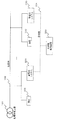
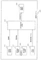
図1は、本実施の形態における周波数制御装置を含む電力系統の構成例を示すブロック図である。 FIG. 1 is a block diagram illustrating a configuration example of a power system including a frequency control device according to the present embodiment.
図1に示されるように、当該電力系統は、配電用変圧器101と、配電線102と、負荷103と、通信線104と、蓄電池システム200と、周波数制御装置300とを備える。
As shown in FIG. 1, the power system includes a
配電用変圧器101は、上位系統から供給される電力を負荷103に供給するのに適切な電圧に変換する変圧器である。
The
配電線102は、配電用変圧器101と負荷103とを電気的に接続し、配電用変圧器101が供給する電力を負荷103に供給するための電力線である。
The
負荷103は、高圧需要家や低圧需要家が保持している機器であり、電力を消費する。負荷103は、例えば、家庭用電気機器などである。
The
通信線104は、周波数制御装置300と蓄電池システム200とが通信できるように接続する。通信線104は、例えば、IEEE802.3規格等に適合する有線LAN、IEEE802.11a、b、g規格等に適合する無線LAN、携帯電話回線等のような公衆通信回線などにより実現される。
The
蓄電池システム200は、電力系統から供給される電力を充電すること、又は、放電して電力系統へ電力を供給することを行う。蓄電池システム200は、上記のように充電又は放電を行うことで、電力系統から供給される電力の周波数を、基準周波数に近づけるように制御する。基準周波数は、例えば50Hzである。
The
蓄電池システム200は、蓄電池、及び蓄電池を充電する際にAC/DC変換を行い、若しくは、蓄電池から放電する際にDC/AC変換を行うインバータ等を含むものとする。
The
蓄電池システム200は、電力系統から供給される電力の周波数を検知し、検知した周波数に基づいて、電力系統の電力の周波数を基準周波数に近づけるように、充放電指令値を算出する。さらに、蓄電池システム200は、当該充放電指令値に周波数制御装置300から受信した配分ゲインを乗算することで、当該充放電指令値を補正し、補正した充放電指令値に基づいて充電又は放電する。
The
周波数制御装置300は、予め、蓄電池システム200のインバータ定格、あるいはインバータ効率最大となる電力値に基づいて、周波数範囲と配分ゲインを算出し、蓄電池システム200に送信する。
The
なお、図1は一例であり、蓄電池システム200は、負荷103なしで配電線102に接続してもよい。また、蓄電池システム200は、配電用変圧器101の上位系統に接続してもよい。
FIG. 1 is an example, and the
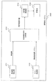
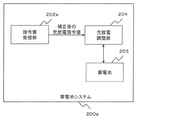
図2は、本実施の形態における蓄電池システムの構成例を示す機能ブロック図である。図2に示されるように、蓄電池システム200は、周波数検出部201と、ゲイン受信部202と、充放電指令値生成部203と、充放電調整部204と、蓄電池205とを備える。
FIG. 2 is a functional block diagram showing a configuration example of the storage battery system in the present embodiment. As shown in FIG. 2, the
周波数検出部201は、電力系統の周波数を検出し、充放電指令値生成部203に送信する。電力系統は、基準周波数(例えば、50Hz又は60Hz。以降では、50Hzの場合を説明する)に近い周波数の交流電力を供給しており、供給される周波数は電力の需給バランスによって変動する。具体的には、電力の需要の方が供給より大きい場合には、電力系統の周波数が低下し、例えば、49.9Hz又は49.8Hzなどとなる。反対に、電力の供給の方が需要より大きい場合には、電力系統の周波数が上昇し、例えば、50.1Hz又は50.2Hzなどとなる。電力系統の周波数は上記のように絶えず変化しており、このように変化している周波数を周波数検出部201が検出する。継続的に周波数制御を行う場合、周波数検出部201は、定期的(例えば、1秒おきに)周波数を検出する。
The
ゲイン受信部202は、周波数制御装置300から周波数範囲とゲインを受信し、充放電指令値生成部203に送信する。例えば、<〜49.9Hz、1><49.9Hz〜50.1Hz、2><50.1Hz〜、1>といった周波数範囲とゲインを受信する。
The
充放電指令値生成部203は、周波数検出部201から受信した周波数に基づいて、電力系統の電力の周波数を基準周波数50Hzに近づけるように、充放電指令値を算出する。例えば、算出した充放電指令値を50kWとする。算出方法について、後で詳しく説明する。さらに、充放電指令値生成部203は、当該充放電指令値にゲイン受信部202から受信した配分ゲインを乗算することで、当該充放電指令値を補正する。例えば、周波数検出部201から受信した周波数の値が49.9Hzであった場合は、ゲイン受信部202から受信した<49.9Hz〜50.1Hz、2>に該当するため、50kWにゲイン(=2)を乗算し、充放電指令値を100kWに補正する(ただし、充放電指令値≦蓄電池システムの定格出力である)。補正した充放電指令値を充放電調整部204に送信する。
Based on the frequency received from the
充放電調整部204は、蓄電池205からの直流電力を交流電力に変換して電力系統に放電する、または、電力系統からの交流電力を直流電力に変換して蓄電池205を充電する双方向インバータを内部に有し、充放電指令値生成部203から受信した充放電指令値に基づいてインバータを制御することで充電又は放電を行う。
The charging / discharging
蓄電池205は、充電および放電可能な二次電池である。
The
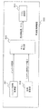
図3は、本実施の形態における周波数制御装置の構成例を示す機能ブロック図である。 FIG. 3 is a functional block diagram illustrating a configuration example of the frequency control device according to the present embodiment.
図3に示されるように、周波数制御装置300は、インバータ定格取得部301と、インバータ効率取得部302と、ゲイン算出部303と、ゲイン送信部304とを備える。
As shown in FIG. 3, the
インバータ定格取得部301は、蓄電池システム200のインバータの定格容量を取得し、ゲイン算出部303に送信する。なお、インバータの定格容量は、インバータ定格取得部301が通信線104を介して蓄電池システム200から取得してもよいし、予め記憶部(図示せず)に保存しておき、インバータ定格取得部301が記憶部から読み込むようにしてもよい。インバータの定格容量は、例えば100kWである。
The inverter
効率取得部302は、蓄電池システム200の効率が最大となる出力電力値を取得し、ゲイン算出部303に送信する。ここで、蓄電池システム200の効率とは、蓄電池の効率に、インバータの効率(つまり変換効率)を乗算した値である。なお、蓄電池システム200の効率をインバータの効率としてもよい。なお、効率が最大となる出力電力値は、効率取得部302が通信線104を介して蓄電池システム200から取得してもよいし、予め記憶部(図示せず)に保存しておき、効率取得部302が記憶部から読み込むようにしてもよい。なお、ゲインの算出にインバータ定格取得部301の取得するインバータ定格を用いる場合は、効率取得部302は不要である。
The
ゲイン算出部303は、インバータ定格取得部301が取得したインバータ定格、または効率取得部302が取得した効率が最大となる出力電力値を用いて、周波数範囲、及びゲインを算出する。算出方法について、後で詳しく説明する。ゲイン送信部304は、通信線104を介して、ゲイン算出部303が算出した周波数範囲とゲインを、蓄電池システム200に送信する。
The
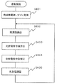
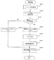
図4は、本実施の形態における蓄電池システムの動作例を示すフローチャートである。 FIG. 4 is a flowchart showing an operation example of the storage battery system in the present embodiment.
ステップS401において、ゲイン受信部202は、周波数範囲とゲインを受信する。ここで、ゲイン受信部202は、周波数制御を開始する前に、周波数範囲とゲインを受信する。
In step S401, the
ステップS402において、周波数検出部201は、電力系統の周波数を検出する。
In step S402, the
ステップS403において、充放電指令値生成部203は、周波数検出部201から受信した周波数に基づいて、電力系統の電力の周波数を基準周波数50Hzに近づけるように、充放電指令値を算出する。具体的には、充放電指令値は、例えば(式1)により求められる。(式1)において、充放電指令値が正となる場合は放電指令値であり、負となる場合は充電指令値である。
In step S403, the charge / discharge command
(充放電指令値)
=(−1)×(周波数偏差)÷(周波数許容偏差)×(インバータ容量) (式1)
(Charge / discharge command value)
= (-1) x (frequency deviation) ÷ (frequency tolerance) x (inverter capacity) (Equation 1)
ここで、周波数偏差は、例えば(式2)により求められる。周波数許容偏差は、例えば(式3)により求められる。基準周波数を50Hz、周波数適正範囲を50Hz±0.2Hzとした場合、周波数許容偏差は0.2Hzとなる。 Here, the frequency deviation is obtained by, for example, (Equation 2). The frequency tolerance is obtained by, for example, (Equation 3). When the reference frequency is 50 Hz and the appropriate frequency range is 50 Hz ± 0.2 Hz, the frequency tolerance is 0.2 Hz.
(周波数偏差)=(検出した周波数)−(基準周波数) (式2)
(周波数許容偏差)
=abs((周波数適正範囲の最大値または最小値)−(基準周波数)) (式3)
(Frequency deviation) = (detected frequency) − (reference frequency) (formula 2)
(Frequency tolerance)
= Abs ((maximum value or minimum value of appropriate frequency range)-(reference frequency)) (Expression 3)
なお、(式1)において、abs(周波数偏差)>周波数許容偏差となる場合は、(周波数偏差)=sign(周波数偏差)×(周波数許容偏差)とする。すなわち、充放電指令値は、インバータ容量を上回ることはない。 In (Expression 1), when abs (frequency deviation)> frequency allowable deviation is satisfied, (frequency deviation) = sign (frequency deviation) × (frequency allowable deviation). That is, the charge / discharge command value does not exceed the inverter capacity.
ステップS404において、充放電指令値生成部203は、ステップS403において算出した充放電指令値にゲイン受信部202から受信した配分ゲインを乗算することで、当該充放電指令値を補正する。具体的には、充放電指令値は、(式4)により補正される。
In step S404, the charge / discharge command
(充放電指令値)=(充放電指令値)×(ゲイン) (式4) (Charge / discharge command value) = (Charge / discharge command value) × (Gain) (Formula 4)
ステップS405において、充放電調整部204は、充放電指令値生成部203から受信した充放電指令値に基づいてインバータを制御することで充電又は放電を行う。ステップS405終了後は、ステップS402に戻る。
In step S405, the charge /
なお、周波数範囲、ゲインを定期的に受信するようにしてもよい。具体的には、ステップS405終了後、ステップS401に戻るようにしてもよい。 Note that the frequency range and gain may be received periodically. Specifically, after step S405 ends, the process may return to step S401.
図5は、本実施の形態における周波数制御装置の動作例を示すフローチャートである。 FIG. 5 is a flowchart showing an operation example of the frequency control apparatus according to the present embodiment.
ステップS501において、インバータ定格取得部301は、蓄電池システム200のインバータの定格容量を取得する。
In step S <b> 501, the inverter
ステップS502において、効率が最大となる出力電力値を取得する。ゲインの算出にインバータ定格取得部301の取得するインバータ定格を用いる場合は、ステップS502は不要である。つまり、ステップS502は必須ではない。
In step S502, an output power value that maximizes efficiency is acquired. When the inverter rating acquired by the inverter
制御対象の蓄電池システムの台数が1台である場合(ステップS503において、1台)、すべてのゲインを1にする(ステップS504)。例えば、<〜49.9Hz、1><49.9Hz〜50.1Hz、1><50.1Hz〜、1>である。これにより、制御対象の蓄電池システムの台数によらず、蓄電池システムの動作を共通化することが可能である。 When the number of storage battery systems to be controlled is one (one in step S503), all gains are set to 1 (step S504). For example, <˜49.9 Hz, 1> <49.9 Hz˜50.1 Hz, 1> <50.1 Hz˜1>. Thereby, it is possible to make common operation | movement of a storage battery system irrespective of the number of the storage battery systems to be controlled.
制御対象の蓄電池システムの台数が複数の場合(ステップS503において、N台)、ゲイン算出部303は、蓄電池システムの順序を決定する(ステップS505)。ここでいう順序が1番の蓄電池システムは、複数の周波数範囲のすべての周波数範囲で放電または充電させることを意味する。順序が2番の蓄電池システムは、第1の周波数範囲以外の周波数範囲で放電または充電させることを意味する。順序が3番の蓄電池システムは、第1および第2の周波数範囲以外の周波数範囲で放電または充電させることを意味する。以下同様である。
When there are a plurality of storage battery systems to be controlled (N in step S503),
具体的には、蓄電池システムのインバータ容量が同一である場合には、劣化が小さい蓄電池システム、あるいは残存容量の大きい蓄電池システムから順に選択していく。なお、使用頻度の高い、あるいは低い蓄電池システムから順に選択するようにしてもよい。 Specifically, when the inverter capacity of the storage battery system is the same, the storage battery system having a small deterioration or the storage battery system having a large remaining capacity is selected in order. In addition, you may make it select in order from a storage battery system with high frequency of use or low.
蓄電池システムのインバータ容量が異なる場合には、インバータの総合効率の算出方法に応じて、蓄電池システムのインバータ容量が小さい順、または大きい順に選択する。具体的には、インバータの総合効率を各蓄電池システムのインバータ効率の平均とする場合は、蓄電池システムのインバータの容量が小さい順に選択する。インバータの総合効率を各蓄電池システムのインバータ効率の加重平均とする場合は、蓄電池システムのインバータの容量が大きい順に選択する。 When the inverter capacities of the storage battery systems are different, the storage battery system is selected in ascending order of the inverter capacities according to the calculation method of the total efficiency of the inverter. Specifically, when the total efficiency of the inverter is the average of the inverter efficiency of each storage battery system, the inverters of the storage battery system are selected in ascending order of capacity. When the total efficiency of the inverter is a weighted average of the inverter efficiency of each storage battery system, the inverter is selected in descending order of the capacity of the storage battery system.
ステップS506において、ゲイン算出部303は、ゲインを算出する。つまり、複数の周波数範囲のそれぞれに対する補正係数であるゲインを算出する。補正係数であるゲインは、充放電指令値に乗算すべき係数である。ゲインの算出にインバータ定格取得部301の取得するインバータ定格を用いる場合は、(式5)及び(式6)を用いて周波数範囲ごとに各蓄電池システム200のゲインを算出する。
In step S506, the
(第iの周波数範囲で使用する蓄電池システム200のゲイン)
=(全蓄電池システム200のインバータ定格の合計)÷(第iの周波数範囲で使用する
蓄電池システム200のインバータ定格の合計) (式5)
(第iの周波数範囲で使用しない蓄電池システム200のゲイン)=0 (式6)
(Gain of
= (Total of inverter ratings of all storage battery systems 200) / (Total of inverter ratings of
(Gain of
具体的に、例えば、100kWの蓄電池システムを2台用い、ゲインの算出にインバータ定格取得部301の取得するインバータ定格を用いる場合は、1台で動作する第1の周波数範囲においては、(100kW+100kW)÷100kWとなり、第1の蓄電池システム200のゲインは2となる。(式6)より、第2の蓄電池システム200のゲインは0となる。2台で動作する第2の周波数範囲においては(100kW+100kW)÷200kWとなり、ゲインはそれぞれ1となる。
Specifically, for example, in the case where two 100 kW storage battery systems are used and the inverter rating acquired by the inverter
ステップS507において、ゲイン算出部303は、周波数範囲を算出する。例えば、周波数範囲はステップS506で算出したゲインを用いて算出する。
In step S507, the
第1の周波数範囲は、(基準周波数)−(周波数許容偏差)÷(ゲイン)〜(基準周波数)+(周波数許容偏差)÷(ゲイン)となる。 The first frequency range is (reference frequency)-(frequency allowable deviation) / (gain) to (reference frequency) + (frequency allowable deviation) / (gain).
第i(i>1)の周波数範囲は、(第i−1の周波数範囲の下限値)−(周波数許容偏差)÷(ゲイン)〜(第i−1の周波数範囲の下限値)、及び(第i−1の周波数範囲の上限値)〜(第i−1の周波数範囲の上限値)+(周波数許容偏差)÷(ゲイン)となる。ただし、周波数上限値、及び周波数下限値を逸脱する場合は、第iの周波数範囲の上限値を周波数上限値、第iの周波数範囲の下限値を周波数下限値とする。 The i-th (i> 1) frequency range is (lower limit value of (i-1) th frequency range) − (frequency tolerance) ÷ (gain) to (lower limit value of (i−1) th frequency range), and ( (The upper limit value of the (i-1) th frequency range) to (the upper limit value of the (i-1) th frequency range) + (frequency allowable deviation) / (gain). However, when deviating from the frequency upper limit value and the frequency lower limit value, the upper limit value of the i-th frequency range is the frequency upper limit value, and the lower limit value of the i-th frequency range is the frequency lower limit value.
ステップS506では、複数の周波数範囲のうち、現在の周波数が属する周波数範囲が基準周波数から離れた周波数範囲であるほど、電力系統に放電するまたは電力系統から供給される電力を充電する蓄電装置の台数が増加するようにゲインを算出する。 In step S506, the number of power storage devices that discharge to the power grid or charge the power supplied from the power grid as the frequency range to which the current frequency belongs is a frequency range farther from the reference frequency among the plurality of frequency ranges. The gain is calculated so as to increase.
具体的には、1台で動作する第1の周波数範囲は、50Hz−(0.2Hz÷2)=49.9Hzから50Hz+(0.2Hz÷2)=50.1Hzとなる。2台で動作する第2の周波数範囲は、49.8Hz〜49.9Hzと、50.1Hz〜50.2Hzとなる。 Specifically, the first frequency range in which one unit operates is 50 Hz− (0.2 Hz ÷ 2) = 49.9 Hz to 50 Hz + (0.2 Hz ÷ 2) = 50.1 Hz. The 2nd frequency range which operate | moves by 2 units | sets will be 49.8Hz-49.9Hz and 50.1Hz-50.2Hz.
なお、ステップS507において、ゲインの算出に効率取得部302の取得するシステム効率ピーク電力を用いる場合は、ゲイン算出部303は、例えば、以下の通り、周波数範囲を算出する。
In step S507, when the system efficiency peak power acquired by the
第1の周波数範囲は、(基準周波数)−(周波数許容偏差)÷(ゲイン)×((システム効率ピーク)÷(インバータ定格))〜(基準周波数)+(周波数許容偏差)÷(ゲイン)×((システム効率ピーク)÷(インバータ定格))となる。 The first frequency range is (reference frequency)-(frequency tolerance) / (gain) x ((system efficiency peak) / (inverter rating)) to (reference frequency) + (frequency tolerance) / (gain) x ((System efficiency peak) ÷ (Inverter rating)).
第i(i>1)の周波数範囲は、(第i−1の周波数範囲の下限値)−(周波数許容偏差)÷(ゲイン)×((システム効率ピーク)÷(インバータ定格))〜(第i−1の周波数範囲の下限値)、及び(第i−1の周波数範囲の上限値)〜(第i−1の周波数範囲の上限値)+(周波数許容偏差)÷(ゲイン)×((システム効率ピーク)÷(インバータ定格))となる。ただし、周波数上限値、及び周波数下限値を逸脱する場合は、第iの周波数範囲の上限値を周波数上限値、第iの周波数範囲の下限値を周波数下限値とする。 The frequency range of the i-th (i> 1) is (lower limit value of the (i-1) -th frequency range) − (frequency allowable deviation) ÷ (gain) × ((system efficiency peak) ÷ (inverter rating)) to (the first). (i−1 frequency range lower limit value), and (i−1th frequency range upper limit value) to (i−1th frequency range upper limit value) + (frequency allowable deviation) ÷ (gain) × (( System efficiency peak) ÷ (inverter rating)). However, when deviating from the frequency upper limit value and the frequency lower limit value, the upper limit value of the i-th frequency range is the frequency upper limit value, and the lower limit value of the i-th frequency range is the frequency lower limit value.
ステップS508において、ゲイン送信部304は、通信線104を介して、ゲイン算出部303が算出した周波数範囲とゲインを、蓄電池システム200に送信する。
In step S <b> 508, the
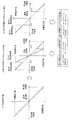
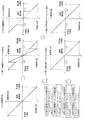
図6は、本実施の形態におけるゲインの決定方法の説明図である。蓄電池システム200の台数を2台とし、インバータ容量は同一(100kW)の場合の例である。また、ゲインの算出にはインバータ定格を用いるものとする。
FIG. 6 is an explanatory diagram of a gain determination method in the present embodiment. This is an example in which the number of
図6(a)は、(式1)を図にしたものである。横軸が測定した周波数であり(周波数偏差でもよい)、縦軸がそのときの充放電指令値となる。周波数上限値のときの充放電指令値は充電最大値となり、周波数下限値のときの充放電指令値は放電最大値となる。また、基準周波数の場合は、充放電指令値は0となる。なお、図6(a)、及び(式1)は一例であり、これに限定されるものではない。このように、充放電指令値は、放電特性データおよび充電特性データにおいて周波数に対して一意に示される放電電力または充電電力を示している。ここで、放電特性データは、前記基準周波数での放電電力が0であり、前記下限周波数での放電電力が前記第1の蓄電装置における最大の放電電力であり、かつ、放電電力が所定の増加率で0から前記最大の放電電力まで増加する放電特性を示す。この放電特性データは、図6(a)の第2象限(左上)の放電特性が該当する。 FIG. 6A illustrates (Equation 1). The horizontal axis represents the measured frequency (may be a frequency deviation), and the vertical axis represents the charge / discharge command value at that time. The charge / discharge command value at the frequency upper limit value is the maximum charge value, and the charge / discharge command value at the frequency lower limit value is the discharge maximum value. In the case of the reference frequency, the charge / discharge command value is zero. In addition, Fig.6 (a) and (Formula 1) are examples, and are not limited to this. Thus, the charge / discharge command value indicates the discharge power or the charge power that is uniquely indicated with respect to the frequency in the discharge characteristic data and the charge characteristic data. Here, in the discharge characteristic data, the discharge power at the reference frequency is 0, the discharge power at the lower limit frequency is the maximum discharge power in the first power storage device, and the discharge power is increased by a predetermined amount. The discharge characteristic increases from 0 to the maximum discharge power at a rate. This discharge characteristic data corresponds to the discharge characteristic in the second quadrant (upper left) of FIG.
また、充電特性データは、基準周波数での充電電力が0であり、上限周波数での充電電力が前記第1の蓄電装置における最大の充電電力であり、かつ、充電電力が所定の増加率で0から前記最大の充電電力まで増加する充電特性を示す。この充電特性データは、図6(a)の第4象限(右下)の充電特性が該当する。 The charging characteristic data indicates that charging power at a reference frequency is 0, charging power at an upper limit frequency is the maximum charging power in the first power storage device, and charging power is 0 at a predetermined increase rate. The charging characteristics increase from 1 to the maximum charging power. This charging characteristic data corresponds to the charging characteristic in the fourth quadrant (lower right) of FIG.
なお、図6(a)では充放電指令値が直線状に変化する例を示したが、充放電指令値は階段状あるいは曲線状に変化してもよい。 Although FIG. 6A shows an example in which the charge / discharge command value changes linearly, the charge / discharge command value may change stepwise or curvedly.
図6(b)は、第1の蓄電池システムの補正方法を、図6(c)は第2の蓄電池システムの補正方法をそれぞれ表している。横軸が測定した周波数であり、縦軸がそのときの充放電指令値となる。なお、説明を簡単にするために、周波数が基準周波数を下回るケースについてのみ説明する。 FIG. 6B shows a correction method for the first storage battery system, and FIG. 6C shows a correction method for the second storage battery system. The horizontal axis is the measured frequency, and the vertical axis is the charge / discharge command value at that time. In order to simplify the description, only the case where the frequency is lower than the reference frequency will be described.
図6(b)において、第1の周波数範囲では、充放電指令値(点線)に対し、補正後の充放電指令値(実線)は2倍になっている。これはゲイン2を乗算したためである(ゲイン=(100kW+100kW)÷100kW)。一方、図6の(c)において、第1の周波数範囲では、充放電指令値(点線)に対し、補正後の充放電指令値(実線)は0となっている。これはゲイン0を乗算したためである。これにより、放電が小さい範囲(第1の周波数範囲)では、第1の蓄電池システムのみが放電を行うこととなり、第1の蓄電池システムは効率の高いところで放電を行うことが可能となる。
In FIG. 6B, in the first frequency range, the corrected charge / discharge command value (solid line) is doubled with respect to the charge / discharge command value (dotted line). This is because gain 2 is multiplied (gain = (100 kW + 100 kW) ÷ 100 kW). On the other hand, in FIG. 6C, the corrected charge / discharge command value (solid line) is 0 with respect to the charge / discharge command value (dotted line) in the first frequency range. This is because
次に、図6(b)及び図6(c)において、第2の周波数範囲では、充放電指令値(点線)と補正後の充放電指令値(実線)とは一致している。これはゲインが1であるためである(ゲイン=(100kW+100kW)÷200kW)。 Next, in FIG. 6B and FIG. 6C, the charge / discharge command value (dotted line) and the corrected charge / discharge command value (solid line) coincide with each other in the second frequency range. This is because the gain is 1 (gain = (100 kW + 100 kW) ÷ 200 kW).
なお、図6(b)及び図6(c)では第2の周波数において、第1の蓄電池システムの充放電指令値と第2の蓄電池システムの充放電指令値が同じになるようにしたが、すわなち、それぞれのゲインを1としたが、これに限定されるものではない。例えば、一部の範囲で第1の蓄電池システムのゲインを1.5、第2の蓄電池システムのゲインを0.5としてもよい。 6 (b) and 6 (c), the charge / discharge command value of the first storage battery system and the charge / discharge command value of the second storage battery system are set to be the same at the second frequency. That is, although each gain is set to 1, it is not limited to this. For example, the gain of the first storage battery system may be 1.5 and the gain of the second storage battery system may be 0.5 in a partial range.
図7は、本実施の形態における蓄電池システムの効率の説明図である。 FIG. 7 is an explanatory diagram of the efficiency of the storage battery system in the present embodiment.
横軸は充電または放電の大きさを表し、縦軸はそのときの蓄電池システム200の効率である。一般的に、充電(または放電)が大きくなるにつれ効率が高くなるが、効率が最大となる出力電力値は充電最大値(または放電最大値)ではない。図7の例では、充電最大値(または放電最大値)の約70〜80%の出力電力値が、効率が最大になる。また、最大効率は、一般的に90%以上であり、例えば95%である。
The horizontal axis represents the magnitude of charging or discharging, and the vertical axis represents the efficiency of the
なお、図7は一例であり、複数の蓄電池システムにおいて効率の曲線が一致するとは限らない。また、ある蓄電池システムにおいても充電時の効率の曲線と放電時の効率の曲線が同じとは限らない。その場合には、充電側と放電側で異なるゲインを設定する。なお、本実施の形態では、蓄電池システム200の効率とは、蓄電池の効率に、インバータの効率を乗算した値とするが、これに限定されるものではなく、例えば蓄電池システム200の効率をインバータの効率としてもよい。
FIG. 7 is an example, and efficiency curves do not always match in a plurality of storage battery systems. In some storage battery systems, the efficiency curve during charging and the efficiency curve during discharging are not always the same. In that case, different gains are set on the charge side and the discharge side. In the present embodiment, the efficiency of the
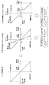
図8は、本実施の形態におけるゲインの決定方法の説明図である。蓄電池システム200の台数を2台とし、インバータ容量が異なる場合の例である。第2の蓄電池システムのインバータ容量を、第1の蓄電池システムのインバータ容量(100kW)の2倍の200kWとする。また、インバータ容量の小さい蓄電池システムから選択するものとする。すなわち、第1の蓄電池システムから選択するものとする。
FIG. 8 is an explanatory diagram of a gain determination method in the present embodiment. This is an example in which the number of
図8(a)は、(式1)を図にしたものである。横軸が測定した周波数であり、縦軸がそのときの充放電指令値となる。周波数上限値のときの充放電指令値は充電最大値となり、周波数下限値のときの充放電指令値は放電最大値となる。また、基準周波数の場合は、充放電指令値は0となる。なお、図8(a)、及び(式1)は一例であり、これに限定されるものではない。 FIG. 8A illustrates (Equation 1). The horizontal axis is the measured frequency, and the vertical axis is the charge / discharge command value at that time. The charge / discharge command value at the frequency upper limit value is the maximum charge value, and the charge / discharge command value at the frequency lower limit value is the discharge maximum value. In the case of the reference frequency, the charge / discharge command value is zero. In addition, Fig.8 (a) and (Formula 1) are examples, and are not limited to this.
図8(b)は、第1の蓄電池システムの補正方法を、図8(c)は第2の蓄電池システムの補正方法をそれぞれ表している。横軸が測定した周波数であり、縦軸がそのときの充放電指令値となる。なお、説明を簡単にするために、周波数が基準周波数を下回るケースについてのみ説明する。 FIG. 8B shows a correction method for the first storage battery system, and FIG. 8C shows a correction method for the second storage battery system. The horizontal axis is the measured frequency, and the vertical axis is the charge / discharge command value at that time. In order to simplify the description, only the case where the frequency is lower than the reference frequency will be described.
図8(b)において、第1の周波数範囲では、充放電指令値(点線)に対し、補正後の充放電指令値(実線)は3倍になっている。これはゲイン3を乗算したためである(ゲイン=(100kW+200kW)÷100kW)。一方、図8の(c)において、第1の周波数範囲では、充放電指令値(点線)に対し、補正後の充放電指令値(実線)は0となっている。これはゲイン0を乗算したためである。これにより、放電が小さい範囲(第1の周波数範囲)では、第1の蓄電池システムのみが放電を行うこととなり、第1の蓄電池システムは効率の高いところで放電を行うことが可能となる。
In FIG. 8B, in the first frequency range, the corrected charge / discharge command value (solid line) is tripled with respect to the charge / discharge command value (dotted line). This is because gain 3 is multiplied (gain = (100 kW + 200 kW) ÷ 100 kW). On the other hand, in FIG. 8C, in the first frequency range, the corrected charge / discharge command value (solid line) is 0 with respect to the charge / discharge command value (dotted line). This is because
次に、図8(b)及び図8(c)において、第2の周波数範囲では、充放電指令値(点線)と補正後の充放電指令値(実線)とは一致している。これはゲインが1であるためである(ゲイン=(100kW+200kW)÷300kW)。 Next, in FIG. 8B and FIG. 8C, the charge / discharge command value (dotted line) and the corrected charge / discharge command value (solid line) coincide with each other in the second frequency range. This is because the gain is 1 (gain = (100 kW + 200 kW) ÷ 300 kW).
なお、図8(b)及び図8(c)では第2の周波数において、第1の蓄電池システムの充放電指令値と第2の蓄電池システムの充放電指令値が同じになるようにしたが、すわなち、それぞれのゲインを1としたが、これに限定されるものではない。例えば、一部の範囲で第1の蓄電池システムのゲインを0.5、第2の蓄電池システムのゲインを1.25としてもよい。 In FIG. 8B and FIG. 8C, the charge / discharge command value of the first storage battery system and the charge / discharge command value of the second storage battery system are made the same at the second frequency. That is, although each gain is set to 1, it is not limited to this. For example, the gain of the first storage battery system may be 0.5 and the gain of the second storage battery system may be 1.25 in a partial range.
図9は、本実施の形態における蓄電池システムの他の構成例を示す機能ブロック図である。図2で説明した構成要素については、同様の符号を付し、詳細な説明を省略することがある。 FIG. 9 is a functional block diagram showing another configuration example of the storage battery system in the present embodiment. The components described in FIG. 2 are denoted by the same reference numerals, and detailed description may be omitted.
図9に示されるように、蓄電池システム200は、周波数検出部201と、ゲイン受信部202と、充放電指令値生成部203と、充放電調整部204と、残存容量取得部901と、残存容量送信部902とを備える。
As shown in FIG. 9, the
残存容量取得部901は、蓄電池の残存容量を取得し、充放電指令値生成部203、及び残存容量送信部902に送信する。
The remaining
充放電指令値生成部203は、残存容量取得部901から受信した残存容量を用いて、充放電指令値を生成し、充放電調整部204に送信する(図4のステップS403)。
The charge / discharge command
残存容量送信部902は、残存容量取得部901から受信した残存容量を、通信線104を介して、周波数制御装置300に送信する。
The remaining
図10は、本実施の形態における周波数制御装置の他の構成例を示す機能ブロック図である。図3で説明した構成要素については、同様の符号を付し、詳細な説明を省略することがある。 FIG. 10 is a functional block diagram showing another configuration example of the frequency control device according to the present embodiment. The components described in FIG. 3 are denoted by the same reference numerals, and detailed description may be omitted.
図10に示されるように、周波数制御装置300は、インバータ定格取得部301と、インバータ効率取得部302と、ゲイン算出部303と、ゲイン送信部304と、残存容量受信部1001とを備える。
As shown in FIG. 10, the
残存容量受信部1001は、蓄電池システム200から残存容量を取得し、ゲイン算出部303に送信する。
The remaining
ゲイン算出部303は、残存容量受信部1001から受信した残存容量を用いて、蓄電池システムの順序を決定する(図5のステップS505)。また、ゲイン算出部303は、残存容量受信部1001から受信した残存容量を用いて、蓄電池システム200のゲインを算出する(図5のステップS506)。残存容量に応じて、ゲインの設定有無を切り替える。例えば、第1の蓄電池システム200の残存容量と、第2の蓄電池システム200の残存容量とがともに45%〜55%の範囲に収まっている場合にはゲインを設定し、どちらかの残存容量が45%〜55%の範囲を逸脱した場合には第1の蓄電池システム200のゲインと第2の蓄電池システム200のゲインを1にする。これにより、残存容量に応じた制御が可能となる。
The
図11は、本実施の形態におけるゲインの決定方法の説明図である。蓄電池システム200の台数を2台とし、インバータ容量は同一(100kW)の場合の例である。また、ゲインの算出にはインバータ定格を用いるものとする。
FIG. 11 is an explanatory diagram of a gain determination method in the present embodiment. This is an example in which the number of
図11(a)は、(式1)を図にしたものである。横軸が測定した周波数であり、縦軸がそのときの充放電指令値となる。周波数上限値のときの充放電指令値は充電最大値となり、周波数下限値のときの充放電指令値は放電最大値となる。また、基準周波数の場合は、充放電指令値は0となる。なお、図11(a)、及び(式1)は一例であり、これに限定されるものではない。 FIG. 11A illustrates (Equation 1). The horizontal axis is the measured frequency, and the vertical axis is the charge / discharge command value at that time. The charge / discharge command value at the frequency upper limit value is the maximum charge value, and the charge / discharge command value at the frequency lower limit value is the discharge maximum value. In the case of the reference frequency, the charge / discharge command value is zero. In addition, Fig.11 (a) and (Formula 1) are examples, and are not limited to this.
図11(b)、図11(c)は、第1の蓄電池システム200の残存容量と、第2の蓄電池システム200の残存容量とがともに45%〜55%の範囲に収まっている場合のそれぞれの補正方法を表している。横軸が測定した周波数であり、縦軸がそのときの充放電指令値となる。
11 (b) and 11 (c) show the cases where the remaining capacity of the first
図11(d)、図11(e)は、どちらかの残存容量が45%〜55%の範囲を逸脱した場合のそれぞれの補正方法を表している。横軸が測定した周波数であり、縦軸がそのときの充放電指令値となる。ゲインはともに1であり、補正する前の充放電指令値(図11(a))と一致している。 FIG. 11D and FIG. 11E show the respective correction methods when either remaining capacity deviates from the range of 45% to 55%. The horizontal axis is the measured frequency, and the vertical axis is the charge / discharge command value at that time. The gains are both 1, which matches the charge / discharge command value before correction (FIG. 11A).
これにより、残存容量に応じた制御が可能となる。例えば、充放電指令値の算出において、残存容量が45%〜55%の範囲に収まっている場合は、(式1)を用い、残存容量が45%〜55%の範囲を逸脱した場合は(式1)に残存容量を考慮した(式7)を用いるといったことが可能となる。なお、(式7)は一例であり、これに限定されるものではない。 Thereby, control according to the remaining capacity becomes possible. For example, in the calculation of the charge / discharge command value, when the remaining capacity is within the range of 45% to 55%, (Equation 1) is used, and when the remaining capacity deviates from the range of 45% to 55% ( It is possible to use (Equation 7) in consideration of the remaining capacity in Equation 1). In addition, (Formula 7) is an example and is not limited to this.
(充放電指令値)
={(−1)×(周波数偏差)÷(周波数許容偏差)+((残存容量)−50%)÷1000}×(インバータ容量) (式7)
(ただし、充放電指令値がインバータ容量を超えた場合はインバータ容量とする)
(Charge / discharge command value)
= {(− 1) × (frequency deviation) ÷ (frequency tolerance) + ((residual capacity) −50%) ÷ 1000} × (inverter capacity) (Expression 7)
(However, if the charge / discharge command value exceeds the inverter capacity, the inverter capacity is assumed.)
(実施の形態2)
本実施の形態において、蓄電池システムを用いて電力系統の周波数を基準周波数に近づける制御を、ある蓄電池システムに組み込まれた周波数制御装置で行う場合について説明する。なお、既に説明した実施の形態と同様の構成要素については、同様の符号を付し、詳細な説明を省略することがある。
(Embodiment 2)
In the present embodiment, a case will be described in which the control of bringing the frequency of the power system closer to the reference frequency using the storage battery system is performed by a frequency control device incorporated in a certain storage battery system. In addition, the same code | symbol is attached | subjected about the component similar to embodiment already demonstrated, and detailed description may be abbreviate | omitted.
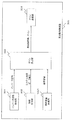
図12は、本実施の形態における周波数制御装置を含む電力系統の構成図である。 FIG. 12 is a configuration diagram of a power system including the frequency control device according to the present embodiment.
図12に示されるように、当該電力系統は、配電用変圧器101と、配電線102と、負荷103と、通信線104と、蓄電池システム200と、蓄電池システム1200とを備える。
As shown in FIG. 12, the power system includes a
蓄電池システム1200は、蓄電池システム200と、周波数制御装置300とを備える。
The
蓄電池システム1200は、予め、蓄電池システム200のインバータ定格、あるいはインバータ効率最大となる電力値に基づいて、周波数範囲と配分ゲインを算出し、蓄電池システム200に送信する。
The
蓄電池システム200、及び蓄電池システム1200は、電力系統から供給される電力の周波数を検知し、検知した周波数に基づいて、電力系統の電力の周波数を基準周波数に近づけるように、充放電指令値を算出する。さらに、蓄電池システム200は、当該充放電指令値に蓄電池システム1200から受信した配分ゲインを乗算することで、当該充放電指令値を補正し、補正した充放電指令値に基づいて充電又は放電する。一方、蓄電池システム1200は、当該充放電指令値に蓄電池システム1200に組み込まれた周波数制御装置300から受信した配分ゲインを乗算することで、当該充放電指令値を補正し、補正した充放電指令値に基づいて充電又は放電する。
The
以上のように本実施の形態に係る周波数制御方法によれば、周波数制御装置が、蓄電池システムに組み込まれていても複数の蓄電池システムを制御することができる。 As described above, according to the frequency control method according to the present embodiment, a plurality of storage battery systems can be controlled even if the frequency control device is incorporated in the storage battery system.
(変形例)
次に、変形例における周波数制御装置を含むシステムについて説明する。上記の実施の形態では、主として、各蓄電池システムが周波数を検出し、検出した周波数に対応する充放電指令値を算出して充放電することにより周波数制御を行う自端型周波数制御について説明した。これに対して変形例では、周波数制御装置が周波数を検出し、検出した周波数に対応する充放電指令値を算出し、当該充放電指令値を各蓄電池システムに指示する集中型周波数制御について説明する。
(Modification)
Next, a system including a frequency control device in a modification will be described. In the above embodiment, the self-end type frequency control in which each storage battery system detects the frequency, calculates the charge / discharge command value corresponding to the detected frequency, and performs charge / discharge to perform frequency control has been described. On the other hand, in the modified example, the frequency control device detects the frequency, calculates the charge / discharge command value corresponding to the detected frequency, and describes the centralized frequency control for instructing each storage battery system with the charge / discharge command value. .
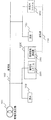
変形例における周波数制御装置を含むシステムの全体構成は、図1または図12と同様である。ただし、変形例におけるシステムは、図1または図12と比べて、蓄電池システム200の代わりに蓄電池システム200aを備える点と、周波数制御装置300の代わりに周波数制御装置300aを備える点とが異なっている。以下異なる点を中心に説明する。
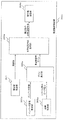
The overall configuration of the system including the frequency control device in the modification is the same as that of FIG. 1 or FIG. However, the system in the modification is different from FIG. 1 or FIG. 12 in that a
図13は、変形例における蓄電池システム200aの構成例を示す機能ブロック図である。同図の蓄電池システム200aは、図2の蓄電池システム200と比べて、周波数検出部201、ゲイン受信部202および充放電指令値生成部203の代わりに指令値受信部202aを備える点が異なっている。
FIG. 13 is a functional block diagram illustrating a configuration example of the
指令値受信部202aは、周波数制御装置300aから、現在の周波数に対応する補正後の充放電指令値を受信し、受信した補正後の充放電指令値を充放電調整部204に出力する。
The command
このように、蓄電池システム200aは、周波数を検出し、検出した周波数に対応する充放電指令値を算出および補正して、補正した充放電指令値に従って充放電するのではなく、周波数制御装置300から、リアルタイムに補正後の充放電指令値を受信し、補正後の充放電指令値に従って充放電する。
Thus, the
これにより各蓄電池システム200aの構成は、図1または図12と比べて簡単な構成にすることができる。
Thereby, the structure of each
図14は、変形例における周波数制御装置300aの構成例を示す機能ブロック図である。同図の周波数制御装置300aは、図3の周波数制御装置300と比べて、インバータ定格取得部301、効率取得部302、ゲイン算出部303およびゲイン送信部304の代わりに、インバータ定格取得部301a、効率取得部302a、ゲイン算出部303aおよび指令値送信部304aを備える点と、周波数検出部201および充放電指令値生成部203aが追加された点とが異なる。以下、異なる点を中心に説明する。
FIG. 14 is a functional block diagram illustrating a configuration example of the
インバータ定格取得部301a、効率取得部302aおよびゲイン算出部303aは、インバータ定格取得部301、効率取得部302およびゲイン算出部303と同じ機能を有する。
The inverter rating acquisition unit 301a, the
インバータ定格取得部301aは、複数の蓄電池システム200aのそれぞれからインバータ定格を取得する。
The inverter rating acquisition unit 301a acquires an inverter rating from each of the plurality of
効率取得部302aは、複数の蓄電池システム200aのそれぞれからインバータ効率を取得する。
ゲイン算出部303aは、複数の周波数範囲のそれぞれに対するゲインを含む補正指示を、前記複数の蓄電装置のそれぞれに対して作成する。
The
充放電指令値生成部203aは、複数の蓄電池システム200aのそれぞれに対応する放電特性データおよび充電特性データを記憶し、周波数検出部201によって検出された周波数に対応する充放電指令値を算出する。さらに、充放電指令値生成部203aは、周波数検出部201によって検出された現在の周波数に対応する充放電指令値を、補正指示に従って前記複数の蓄電装置のそれぞれに対して補正する。
The charge / discharge command
指令値送信部304aは、複数の蓄電池システム200aのそれぞれに、当該蓄電池システム200aに対応する補正された充放電指示を送信する。この補正された充放電指示は、周期的に(例えば、数100m秒〜数秒)、あるいは周波数の変動に応じて送信される。
The command
このように、変形例における周波数制御装置300aおよび複数の蓄電池システム200aは、集中型の周波数制御を行う。しかも、自端型周波数制御よりも簡単な構成で実現することができる。
Thus, the
なお、上記各実施の形態において、各構成要素は、専用のハードウェアで構成されるか、各構成要素に適したソフトウェアプログラムを実行することによって実現されてもよい。各構成要素は、CPUまたはプロセッサなどのプログラム実行部が、ハードディスクまたは半導体メモリなどの記録媒体に記録されたソフトウェアプログラムを読み出して実行することによって実現されてもよい。ここで、上記各実施の形態の周波数制御装置などを実現するソフトウェアは、次のようなプログラムである。 In each of the above embodiments, each component may be configured by dedicated hardware or may be realized by executing a software program suitable for each component. Each component may be realized by a program execution unit such as a CPU or a processor reading and executing a software program recorded on a recording medium such as a hard disk or a semiconductor memory. Here, the software that realizes the frequency control device of each of the above embodiments is a program as follows.
すなわち、このプログラムは、コンピュータに、上記の周波数制御方法を実行させる。 That is, this program causes a computer to execute the above-described frequency control method.
以上、一つまたは複数の態様に係る周波数制御装置について、実施の形態に基づいて説明したが、本開示は、この実施の形態に限定されるものではない。本開示の趣旨を逸脱しない限り、当業者が思いつく各種変形を本実施の形態に施したものや、異なる実施の形態における構成要素を組み合わせて構築される形態も、一つまたは複数の態様の範囲内に含まれてもよい。 As described above, the frequency control device according to one or more aspects has been described based on the embodiment, but the present disclosure is not limited to this embodiment. Unless it deviates from the gist of the present disclosure, various modifications conceived by those skilled in the art have been made in this embodiment, and forms constructed by combining components in different embodiments are also within the scope of one or more aspects. May be included.
なお、図5に示した周波数制御装置の動作例は、運転開始直後だけでなく定期的(例えば、数十分〜数時間に1度)に実行してもよい。こうすれば、蓄電池システム200の残量等の状態の変化に対応して、より総合的な効率を向上させることができる。
Note that the operation example of the frequency control device shown in FIG. 5 may be executed not only immediately after the start of operation but also periodically (for example, several tens of minutes to once every several hours). By so doing, it is possible to improve the overall efficiency in response to changes in the state of the
また、実施の形態1では、蓄電池システム200が、図6(a)のような充放電指令値の特性データを記憶し、補正係数であるゲインを受信し、充放電指令値を補正している。これに対して、蓄電池システム200が、周波数制御装置300から図6(b)、(c)のような充放電指令値を表すデータを受信、記憶してもよい。
Moreover, in
本開示は、電力系統の周波数を基準周波数へ近づけるための制御を行う周波数制御装置に利用可能である。具体的には、電力会社が運用及び管理する電力系統の周波数の制御を行う周波数制御装置に利用可能である。 The present disclosure can be used for a frequency control device that performs control to bring the frequency of the power system close to the reference frequency. Specifically, the present invention can be used for a frequency control device that controls the frequency of a power system operated and managed by an electric power company.
101 配電用変圧器
102 配電線
103 負荷
104 通信線
200、200a 蓄電池システム
201 周波数検出部
202 ゲイン受信部
202a 指令値受信部
203、203a 充放電指令値生成部
204 充放電調整部
205 蓄電池
300、300a 周波数制御装置
301、301a インバータ定格取得部
302、302a 効率取得部(インバータ効率取得部)
303、303a ゲイン算出部
304 ゲイン送信部
304a 指令値送信部
901 残存容量取得部
902 残存容量送信部
1001 残存容量受信部
1200 蓄電池システム
DESCRIPTION OF
303, 303a
Claims (11)
前記周波数制御装置において、予め定められた基準周波数から、予め定められた下限周波数または予め定められた上限周波数までの区間を前記複数の蓄電装置の台数に応じて複数の周波数範囲に分割する分割ステップと、
前記電力系統の現在の周波数を検出する検出ステップと、
前記複数の周波数範囲のうち、前記現在の周波数が属する周波数範囲が前記基準周波数から離れた周波数範囲であるほど、前記電力系統に放電するまたは前記電力系統から供給される電力を充電する蓄電装置の台数が増加するように前記複数の蓄電装置を制御する制御ステップとを有し、
前記複数の周波数範囲は、前記基準周波数との差分の絶対値が0以上で第1の値より小さい第1の周波数範囲と、前記基準周波数との差分の絶対値が前記第1の値以上で第2の値より小さい第2の周波数範囲とを含み、
前記周波数制御方法は、さらに、
前記複数の蓄電装置の劣化度、残存容量、および使用頻度の少なくとも1つに応じて、前記複数の蓄電装置の中から、前記複数の周波数範囲のすべての周波数範囲で放電または充電させる第1の蓄電装置を選択し、前記第1の周波数範囲以外の周波数範囲で放電または充電させる第2の蓄電装置を選択する選択ステップを有し、
前記制御ステップにおいて、前記電力系統の実際の周波数が前記第1の周波数範囲内にある場合に、前記第1の蓄電装置から前記電力系統に放電させ、かつ前記第2の蓄電装置から前記電力系統に放電させないように制御し、または、前記電力系統から前記第1の蓄電装置に充電させ、かつ前記電力系統から前記第2の蓄電装置に充電させないように制御し、
前記第1の蓄電装置は、前記複数の周波数範囲のそれぞれにおいて、前記基準周波数に対する前記現在の周波数の偏差が大きいほど前記第1の蓄電装置から前記電力系統への放電電力を増加させ、または、前記電力系統から前記第1の蓄電装置への充電電力を増加させ、
前記第1の蓄電装置において、前記第1の周波数範囲における前記放電電力または前記充電電力の前記偏差に対する増加率が、他のいずれの周波数範囲における前記放電電力または前記充電電力の前記偏差に対する増加率よりも大きく、
前記第1の周波数範囲において、前記第1の蓄電装置から前記電力系統への前記放電電力は、前記偏差に応じて0から第1の放電電力まで増加し、前記電力系統から前記第1の蓄電装置への前記充電電力は、0から第1の充電電力まで前記偏差に応じて増加し、
前記第2の周波数範囲において、前記第1の蓄電装置から前記電力系統への前記放電電力は、前記第1の放電電力より小さい第2の放電電力から第3の放電電力まで前記偏差に応じて増加し、前記電力系統から前記第1の蓄電装置に充電される前記充電電力は、前記第1の充電電力より小さい第2の充電電力から第3の充電電力まで前記偏差に応じて増加し、
前記制御ステップにおいて、前記第2の周波数範囲において、前記第1の蓄電装置から前記電力系統への前記放電電力の増加率と前記第2の蓄電装置から前記電力系統への放電電力の増加率とを一致させ、前記電力系統から前記第1の蓄電装置への前記充電電力の増加率と前記電力系統から前記第2の蓄電装置への充電電力の増加率とを一致させる
周波数制御方法。 In a system having a plurality of power storage devices and frequency control devices arranged in a distributed manner, the frequency control method controls the frequency of the power system by performing charge / discharge control of the plurality of power storage devices, or maintains a supply-demand balance. And
In the frequency control device, a dividing step of dividing a section from a predetermined reference frequency to a predetermined lower limit frequency or a predetermined upper limit frequency into a plurality of frequency ranges according to the number of the plurality of power storage devices. When,
A detection step of detecting a current frequency of the power system;
Of the plurality of frequency ranges, the more the frequency range to which the current frequency belongs is the frequency range farther from the reference frequency, the more the power storage device that discharges to the power system or charges the power supplied from the power system. It has a control step for the number to control the plurality of power storage devices to increase,
In the plurality of frequency ranges, the absolute value of the difference between the reference frequency and the reference frequency is greater than or equal to 0 and less than the first value, and the absolute value of the difference between the reference frequencies is greater than or equal to the first value. A second frequency range less than the second value,
The frequency control method further includes:
According to at least one of the degree of deterioration, the remaining capacity, and the usage frequency of the plurality of power storage devices, a first discharge or charging is performed in all frequency ranges of the plurality of frequency ranges from among the plurality of power storage devices. Selecting a power storage device and selecting a second power storage device to be discharged or charged in a frequency range other than the first frequency range;
In the control step, when the actual frequency of the power system is within the first frequency range, the first power storage device is discharged to the power system, and the second power storage device is connected to the power system. Or control to prevent the first power storage device from being charged from the power system and not charging the second power storage device from the power system,
In each of the plurality of frequency ranges, the first power storage device increases the discharge power from the first power storage device to the power system as the deviation of the current frequency with respect to the reference frequency increases, or Increasing charging power from the power system to the first power storage device,
In the first power storage device, an increase rate with respect to the deviation of the discharge power or the charge power in the first frequency range is an increase rate with respect to the deviation of the discharge power or the charge power in any other frequency range. Bigger than
In the first frequency range, the discharge power from the first power storage device to the power system increases from 0 to the first discharge power according to the deviation, and the first power storage from the power system. The charging power to the device increases according to the deviation from 0 to the first charging power,
In the second frequency range, the discharge power from the first power storage device to the power system depends on the deviation from a second discharge power smaller than the first discharge power to a third discharge power. The charging power charged from the power system to the first power storage device increases according to the deviation from a second charging power smaller than the first charging power to a third charging power,
In the control step, an increase rate of the discharge power from the first power storage device to the power system and an increase rate of the discharge power from the second power storage device to the power system in the second frequency range The rate of increase in the charging power from the power system to the first power storage device and the rate of increase in the charging power from the power system to the second power storage device are matched to each other Frequency control Method.
蓄電池と、
前記蓄電池からの直流電力を交流電力に変換して前記電力系統に放電する、または、前記電力系統からの交流電力を直流電力に変換して前記蓄電池を充電するインバータとを備え、
前記制御ステップにおいて、前記第1の蓄電装置が備える前記インバータの容量が小さいほど、前記第1の周波数範囲における前記第1の蓄電装置の前記放電電力または前記充電電力の前記増加率は大きい
請求項1に記載の周波数制御方法。 Each of the plurality of power storage devices is
A storage battery,
DC power from the storage battery is converted to AC power and discharged to the power system, or AC power from the power system is converted to DC power to charge the storage battery,
In the control step, as the capacity of the inverter included in the first power storage device is smaller, the increase rate of the discharge power or the charge power of the first power storage device in the first frequency range is larger. frequency control method according to 1.
請求項1に記載の周波数制御方法。 Wherein each of the first discharge power and the first charge power frequency control method according to claim 1 which is the maximum rated value of the first power storage device.
蓄電池と、
前記蓄電池からの直流電力を交流電力に変換して前記電力系統に放電する、または、前記電力系統からの交流電力を直流電力に変換して前記蓄電池を充電するインバータとを備え、
前記第1の放電電力および前記第1の充電電力のそれぞれは、前記第1の蓄電装置が備える前記インバータの変換効率、前記蓄電池の充放電効率、または、前記変換効率と前記充放電効率との積が最大となるときの電力である
請求項1に記載の周波数制御方法。 Each of the plurality of power storage devices is
A storage battery,
DC power from the storage battery is converted to AC power and discharged to the power system, or AC power from the power system is converted to DC power to charge the storage battery,
Each of the first discharge power and the first charge power is a conversion efficiency of the inverter included in the first power storage device, a charge / discharge efficiency of the storage battery, or the conversion efficiency and the charge / discharge efficiency. The frequency control method according to claim 1 , wherein the frequency is electric power when the product becomes maximum.
前記基準周波数での放電電力が0であり、前記下限周波数での放電電力が前記第1の蓄電装置における最大の放電電力であり、かつ、放電電力が所定の増加率で0から前記最大の放電電力まで増加する放電特性データにおいて、前記基準周波数から前記第1の値を減じた周波数における放電電力であり、
前記第2の充電電力は、
前記基準周波数での充電電力が0であり、前記上限周波数での充電電力が前記第1の蓄電装置における最大の充電電力であり、かつ、充電電力が所定の増加率で0から前記最大の充電電力まで増加する充電特性データにおいて、前記基準周波数から前記第1の値を加えた周波数における充電電力である
請求項3または4に記載の周波数制御方法。 The second discharge power is
The discharge power at the reference frequency is 0, the discharge power at the lower limit frequency is the maximum discharge power in the first power storage device, and the discharge power is from 0 to the maximum discharge at a predetermined increase rate. In the discharge characteristic data increasing to power, the discharge power at a frequency obtained by subtracting the first value from the reference frequency,
The second charging power is
The charging power at the reference frequency is 0, the maximum charging power charging power at the upper limit frequency in the first power storage device and charging from 0 the charge power at a predetermined increase rate of the maximum 5. The frequency control method according to claim 3 , wherein in charging characteristic data that increases to electric power, the charging power is a frequency at a frequency obtained by adding the first value to the reference frequency.
前記周波数制御装置において、前記複数の周波数範囲のそれぞれに対する補正係数を含む補正指示を、前記複数の蓄電装置のそれぞれに対して作成するサブステップと、
前記周波数制御装置から前記複数の蓄電装置に、当該蓄電装置に対応する補正指示を送信するサブステップと、
前記複数の蓄電装置のそれぞれにおいて、前記検出ステップにおいて検出された周波数に対応する充放電指令値を前記補正指示に従って補正するサブステップと、
前記複数の蓄電装置のそれぞれにおいて、補正した充放電指令値に従って前記電力系統に放電または前記電力系統から充電するサブステップとを有し、
前記充放電指令値は、前記放電特性データおよび前記充電特性データにおいて周波数に対して一意に示される放電電力または充電電力を示す
請求項5に記載の周波数制御方法。 The control step includes
In the frequency control device, a sub-step of creating a correction instruction including a correction coefficient for each of the plurality of frequency ranges for each of the plurality of power storage devices;
A sub-step of transmitting a correction instruction corresponding to the power storage device from the frequency control device to the plurality of power storage devices;
In each of the plurality of power storage devices, a sub-step of correcting a charge / discharge command value corresponding to the frequency detected in the detection step according to the correction instruction;
In each of the plurality of power storage devices, having a sub-step of discharging to the power system or charging from the power system according to the corrected charge / discharge command value,
The frequency control method according to claim 5 , wherein the charge / discharge command value indicates a discharge power or a charge power that is uniquely indicated with respect to a frequency in the discharge characteristic data and the charge characteristic data.
前記周波数制御装置において、前記複数の周波数範囲のそれぞれに対する補正係数を含む補正指示を、前記複数の蓄電装置のそれぞれに対して作成するサブステップと、
前記検出ステップにおいて検出された周波数に対応する充放電指令値を、前記補正指示に従って前記複数の蓄電装置のそれぞれに対して補正するサブステップと、
前記周波数制御装置から前記複数の蓄電装置のそれぞれに、当該蓄電装置に対応する補正された充放電指令値を送信するサブステップと、
前記複数の蓄電装置のそれぞれにおいて、前記周波数制御装置から送信された補正後の充放電指令値に従って放電または充電するサブステップとを有し、
前記充放電指令値は、前記放電特性データおよび前記充電特性データにおいて周波数に対して一意に示される放電電力または充電電力を示す
請求項5に記載の周波数制御方法。 The control step includes
In the frequency control device, a sub-step of creating a correction instruction including a correction coefficient for each of the plurality of frequency ranges for each of the plurality of power storage devices;
A sub-step of correcting the charge / discharge command value corresponding to the frequency detected in the detection step with respect to each of the plurality of power storage devices according to the correction instruction;
A sub-step of transmitting a corrected charge / discharge command value corresponding to the power storage device to each of the plurality of power storage devices from the frequency control device;
In each of the plurality of power storage devices, having a sub-step of discharging or charging according to a corrected charge / discharge command value transmitted from the frequency control device,
The frequency control method according to claim 5 , wherein the charge / discharge command value indicates a discharge power or a charge power that is uniquely indicated with respect to a frequency in the discharge characteristic data and the charge characteristic data.
予め定められた基準周波数から、予め定められた下限周波数または予め定められた上限周波数までの区間を前記複数の蓄電装置の台数に応じて複数の周波数範囲に分割し、前記複数の蓄電装置のそれぞれに対して前記複数の周波数範囲のそれぞれに対する補正係数であるゲインを算出するゲイン算出部と、
前記電力系統の現在の周波数を検出する検出部と、
前記複数の蓄電装置のそれぞれにおいて、前記検出部において検出された周波数に対応する充放電指令値を前記ゲインに従って補正することによって補正後の充放電指令値を生成する指令値生成部と、
前記複数の蓄電装置のそれぞれに補正後の充放電指令値を送信する送信部とを備え、
前記ゲイン算出部は、前記基準周波数での放電電力が0であり、前記下限周波数での放電電力が第1の蓄電装置における最大の放電電力であり、かつ、放電電力が所定の増加率で0から前記最大の放電電力まで増加する放電特性データと、前記基準周波数での充電電力が0であり、前記上限周波数での充電電力が前記第1の蓄電装置における最大の充電電力であり、かつ、充電電力が所定の増加率で0から前記最大の充電電力まで増加する充電特性データとを記憶し、
前記補正係数である前記ゲインは、充放電指令値に乗算すべき係数であり、
前記充放電指令値は、前記放電特性データおよび前記充電特性データにおいて周波数に対して一意に示される放電電力または充電電力を示し、
前記ゲイン算出部は、前記複数の周波数範囲のうち、前記現在の周波数が属する周波数範囲が前記基準周波数から離れた周波数範囲であるほど、前記電力系統に放電するまたは前記電力系統から供給される電力を充電する蓄電装置の台数が増加するように前記ゲインを算出し、
前記複数の周波数範囲は、前記基準周波数との差分の絶対値が0以上で第1の値より小さい第1の周波数範囲と、前記基準周波数との差分の絶対値が前記第1の値以上で第2の値より小さい第2の周波数範囲とを含み、
前記周波数制御装置は、さらに、
前記複数の蓄電装置の劣化度、残存容量、および使用頻度の少なくとも1つに応じて、前記複数の蓄電装置の中から、前記複数の周波数範囲のすべての周波数範囲で放電または充電させる第1の蓄電装置を選択し、前記第1の周波数範囲以外の周波数範囲で放電または充電させる第2の蓄電装置を選択し、
前記電力系統の実際の周波数が前記第1の周波数範囲内にある場合に、前記第1の蓄電装置から前記電力系統に放電させ、かつ前記第2の蓄電装置から前記電力系統に放電させないように制御し、または、前記電力系統から前記第1の蓄電装置に充電させ、かつ前記電力系統から前記第2の蓄電装置に充電させないように制御し、
前記第1の蓄電装置は、前記複数の周波数範囲のそれぞれにおいて、前記基準周波数に対する前記現在の周波数の偏差が大きいほど前記第1の蓄電装置から前記電力系統への放電電力を増加させ、または、前記電力系統から前記第1の蓄電装置への充電電力を増加させ、
前記第1の蓄電装置において、前記第1の周波数範囲における前記放電電力または前記充電電力の前記偏差に対する増加率が、他のいずれの周波数範囲における前記放電電力または前記充電電力の前記偏差に対する増加率よりも大きく、
前記第1の周波数範囲において、前記第1の蓄電装置から前記電力系統への前記放電電力は、前記偏差に応じて0から第1の放電電力まで増加し、前記電力系統から前記第1の蓄電装置への前記充電電力は、0から第1の充電電力まで前記偏差に応じて増加し、
前記第2の周波数範囲において、前記第1の蓄電装置から前記電力系統への前記放電電力は、前記第1の放電電力より小さい第2の放電電力から第3の放電電力まで前記偏差に応じて増加し、前記電力系統から前記第1の蓄電装置に充電される前記充電電力は、前記第1の充電電力より小さい第2の充電電力から第3の充電電力まで前記偏差に応じて増加し、
前記周波数制御装置は、前記第2の周波数範囲において、前記第1の蓄電装置から前記電力系統への前記放電電力の増加率と前記第2の蓄電装置から前記電力系統への放電電力の増加率とを一致させ、前記電力系統から前記第1の蓄電装置への前記充電電力の増加率と前記電力系統から前記第2の蓄電装置への充電電力の増加率とを一致させる
周波数制御装置。 A frequency control device that controls the frequency of the power system by performing charge / discharge control of a plurality of power storage devices that are dispersedly arranged, or that maintains a balance between supply and demand,
From a predetermined reference frequency, is divided into a plurality of frequency ranges in accordance with section up to the lower limit frequency or predetermined upper limit frequency predetermined for the number of the plurality of power storage devices, each of said plurality of power storage devices A gain calculation unit that calculates a gain that is a correction coefficient for each of the plurality of frequency ranges;
A detection unit for detecting a current frequency of the power system;
In each of the plurality of power storage devices, a command value generation unit that generates a corrected charge / discharge command value by correcting a charge / discharge command value corresponding to the frequency detected by the detection unit according to the gain;
A transmission unit that transmits the corrected charge / discharge command value to each of the plurality of power storage devices,
The gain calculating unit is configured such that the discharge power at the reference frequency is 0, the discharge power at the lower limit frequency is the maximum discharge power in the first power storage device, and the discharge power is 0 at a predetermined increase rate. Discharge characteristic data that increases from the maximum discharge power to the maximum discharge power, the charge power at the reference frequency is 0, the charge power at the upper limit frequency is the maximum charge power in the first power storage device, and charging power store and charge characteristic data increases from 0 at a predetermined increase rate until charge current force of said maximum,
The gain which is the correction coefficient is a coefficient to be multiplied by the charge / discharge command value,
The charge / discharge command value indicates discharge power or charge power that is uniquely indicated with respect to frequency in the discharge characteristic data and the charge characteristic data,
The gain calculation unit is configured to discharge power to the power system or supply power from the power system as the frequency range to which the current frequency belongs is a frequency range farther from the reference frequency among the plurality of frequency ranges. The gain is calculated so that the number of power storage devices that charge the battery increases ,
In the plurality of frequency ranges, the absolute value of the difference between the reference frequency and the reference frequency is greater than or equal to 0 and less than the first value, and the absolute value of the difference between the reference frequencies is greater than or equal to the first value. A second frequency range less than the second value,
The frequency control device further includes:
According to at least one of the degree of deterioration, the remaining capacity, and the usage frequency of the plurality of power storage devices, a first discharge or charging is performed in all frequency ranges of the plurality of frequency ranges from the plurality of power storage devices Select a power storage device, select a second power storage device to be discharged or charged in a frequency range other than the first frequency range,
When the actual frequency of the power system is within the first frequency range, the first power storage device is discharged to the power system, and the second power storage device is not discharged to the power system. Control or control to charge the first power storage device from the power system and not charge the second power storage device from the power system,
In each of the plurality of frequency ranges, the first power storage device increases the discharge power from the first power storage device to the power system as the deviation of the current frequency with respect to the reference frequency increases, or Increasing charging power from the power system to the first power storage device,
In the first power storage device, an increase rate with respect to the deviation of the discharge power or the charge power in the first frequency range is an increase rate with respect to the deviation of the discharge power or the charge power in any other frequency range. Bigger than
In the first frequency range, the discharge power from the first power storage device to the power system increases from 0 to the first discharge power according to the deviation, and the first power storage from the power system. The charging power to the device increases according to the deviation from 0 to the first charging power,
In the second frequency range, the discharge power from the first power storage device to the power system depends on the deviation from a second discharge power smaller than the first discharge power to a third discharge power. The charging power charged from the power system to the first power storage device increases according to the deviation from a second charging power smaller than the first charging power to a third charging power,
In the second frequency range, the frequency control device is configured to increase the discharge power from the first power storage device to the power system and increase the discharge power from the second power storage device to the power system. The rate of increase of the charging power from the power system to the first power storage device and the rate of increase of the charging power from the power system to the second power storage device are matched. Control device.
前記複数の蓄電装置とを備え、
前記複数の蓄電装置のそれぞれは、
前記周波数制御装置から補正後の充放電指令値を受信する受信部と、
蓄電池と、
補正後の充放電指令値に従って、前記蓄電池からの直流電力を交流電力に変換して前記電力系統に放電する、または、前記電力系統からの交流電力を直流電力に変換して前記蓄電池を充電するインバータとを備えるシステム。 A frequency control device according to claim 8 ;
A plurality of power storage devices,
Each of the plurality of power storage devices is
A receiving unit for receiving a corrected charge / discharge command value from the frequency control device;
A storage battery,
According to the corrected charge / discharge command value, DC power from the storage battery is converted to AC power and discharged to the power system, or AC power from the power system is converted to DC power and the storage battery is charged. A system comprising an inverter.
予め定められた基準周波数から、予め定められた下限周波数または予め定められた上限周波数までの区間を前記複数の蓄電装置の台数に応じて複数の周波数範囲に分割し、前記複数の蓄電装置のそれぞれに対して前記複数の周波数範囲のそれぞれに対する補正係数であるゲインを算出するゲイン算出部と、
前記複数の蓄電装置のそれぞれに前記周波数範囲毎の前記ゲインを送信する送信部とを備え、
前記補正係数である前記ゲインは、充放電指令値に乗算すべき係数であり、
前記充放電指令値は、放電特性データおよび充電特性データにおいて周波数に対して一意に示される放電電力または充電電力を示し、
前記放電特性データは、前記基準周波数での放電電力が0であり、前記下限周波数での放電電力が第1の蓄電装置における最大の放電電力であり、かつ、放電電力が所定の増加率で0から前記最大の放電電力まで増加する放電特性を示し、
前記充電特性データは、前記基準周波数での充電電力が0であり、前記上限周波数での充電電力が前記第1の蓄電装置における最大の充電電力であり、かつ、充電電力が所定の増加率で0から前記最大の充電電力まで増加する充電特性を示し、
前記ゲイン算出部は、前記複数の周波数範囲のうち、現在の周波数が属する周波数範囲が前記基準周波数から離れた周波数範囲であるほど、前記電力系統に放電するまたは前記電力系統から供給される電力を充電する蓄電装置の台数が増加するように前記ゲインを算出し、
前記複数の周波数範囲は、前記基準周波数との差分の絶対値が0以上で第1の値より小さい第1の周波数範囲と、前記基準周波数との差分の絶対値が前記第1の値以上で第2の値より小さい第2の周波数範囲とを含み、
前記周波数制御装置は、さらに、
前記複数の蓄電装置の劣化度、残存容量、および使用頻度の少なくとも1つに応じて、前記複数の蓄電装置の中から、前記複数の周波数範囲のすべての周波数範囲で放電または充電させる第1の蓄電装置を選択し、前記第1の周波数範囲以外の周波数範囲で放電または充電させる第2の蓄電装置を選択し、
前記電力系統の実際の周波数が前記第1の周波数範囲内にある場合に、前記第1の蓄電装置から前記電力系統に放電させ、かつ前記第2の蓄電装置から前記電力系統に放電させないように制御し、または、前記電力系統から前記第1の蓄電装置に充電させ、かつ前記電力系統から前記第2の蓄電装置に充電させないように制御し、
前記第1の蓄電装置は、前記複数の周波数範囲のそれぞれにおいて、前記基準周波数に対する前記現在の周波数の偏差が大きいほど前記第1の蓄電装置から前記電力系統への放電電力を増加させ、または、前記電力系統から前記第1の蓄電装置への充電電力を増加させ、
前記第1の蓄電装置において、前記第1の周波数範囲における前記放電電力または前記充電電力の前記偏差に対する増加率が、他のいずれの周波数範囲における前記放電電力または前記充電電力の前記偏差に対する増加率よりも大きく、
前記第1の周波数範囲において、前記第1の蓄電装置から前記電力系統への前記放電電力は、前記偏差に応じて0から第1の放電電力まで増加し、前記電力系統から前記第1の蓄電装置への前記充電電力は、0から第1の充電電力まで前記偏差に応じて増加し、
前記第2の周波数範囲において、前記第1の蓄電装置から前記電力系統への前記放電電力は、前記第1の放電電力より小さい第2の放電電力から第3の放電電力まで前記偏差に応じて増加し、前記電力系統から前記第1の蓄電装置に充電される前記充電電力は、前記第1の充電電力より小さい第2の充電電力から第3の充電電力まで前記偏差に応じて増加し、
前記周波数制御装置は、前記第2の周波数範囲において、前記第1の蓄電装置から前記電力系統への前記放電電力の増加率と前記第2の蓄電装置から前記電力系統への放電電力の増加率とを一致させ、前記電力系統から前記第1の蓄電装置への前記充電電力の増加率と前記電力系統から前記第2の蓄電装置への充電電力の増加率とを一致させる
周波数制御装置。 A frequency control device that controls the frequency of the power system by performing charge / discharge control of a plurality of power storage devices that are dispersedly arranged, or that maintains a balance between supply and demand,
From the reference frequency defined Me pre, is divided into a plurality of frequency ranges in accordance with section up to the lower limit frequency or predetermined upper limit frequency predetermined for the number of the plurality of power storage devices, the plurality of power storage devices A gain calculation unit that calculates a gain that is a correction coefficient for each of the plurality of frequency ranges,
A transmission unit that transmits the gain for each frequency range to each of the plurality of power storage devices;
The gain which is the correction coefficient is a coefficient to be multiplied by the charge / discharge command value,
The charge / discharge command value indicates discharge power or charge power that is uniquely indicated for the frequency in the discharge characteristic data and the charge characteristic data,
In the discharge characteristic data, the discharge power at the reference frequency is 0, the discharge power at the lower limit frequency is the maximum discharge power in the first power storage device, and the discharge power is 0 at a predetermined increase rate. Showing discharge characteristics increasing from the maximum discharge power to
In the charging characteristic data, the charging power at the reference frequency is 0, the charging power at the upper limit frequency is the maximum charging power in the first power storage device, and the charging power is at a predetermined increase rate. 0 indicates the charging characteristics increases to charge current force of said maximum,
The gain calculation unit is configured to discharge power to the power system or supply power from the power system as a frequency range to which a current frequency belongs is a frequency range far from the reference frequency among the plurality of frequency ranges. Calculate the gain so that the number of power storage devices to be charged increases ,
In the plurality of frequency ranges, the absolute value of the difference between the reference frequency and the reference frequency is greater than or equal to 0 and less than the first value, and the absolute value of the difference between the reference frequencies is greater than or equal to the first value. A second frequency range less than the second value,
The frequency control device further includes:
According to at least one of the degree of deterioration, the remaining capacity, and the usage frequency of the plurality of power storage devices, a first discharge or charging is performed in all frequency ranges of the plurality of frequency ranges from among the plurality of power storage devices. Select a power storage device, select a second power storage device to be discharged or charged in a frequency range other than the first frequency range,
When the actual frequency of the power system is within the first frequency range, the first power storage device is discharged to the power system, and the second power storage device is not discharged to the power system. Control or control to charge the first power storage device from the power system and not charge the second power storage device from the power system,
In each of the plurality of frequency ranges, the first power storage device increases the discharge power from the first power storage device to the power system as the deviation of the current frequency with respect to the reference frequency increases, or Increasing charging power from the power system to the first power storage device,
In the first power storage device, an increase rate with respect to the deviation of the discharge power or the charge power in the first frequency range is an increase rate with respect to the deviation of the discharge power or the charge power in any other frequency range. Bigger than
In the first frequency range, the discharge power from the first power storage device to the power system increases from 0 to the first discharge power according to the deviation, and the first power storage from the power system. The charging power to the device increases according to the deviation from 0 to the first charging power,
In the second frequency range, the discharge power from the first power storage device to the power system depends on the deviation from a second discharge power smaller than the first discharge power to a third discharge power. The charging power charged from the power system to the first power storage device increases according to the deviation from a second charging power smaller than the first charging power to a third charging power,
In the second frequency range, the frequency control device is configured to increase the discharge power from the first power storage device to the power system and increase the discharge power from the second power storage device to the power system. The rate of increase of the charging power from the power system to the first power storage device and the rate of increase of the charging power from the power system to the second power storage device are matched. Control device.
前記複数の蓄電装置とを備える
システム。 A frequency control device according to claim 10 ;
A system comprising the plurality of power storage devices.
Priority Applications (1)
| Application Number | Priority Date | Filing Date | Title |
|---|---|---|---|
| JP2015110035A JP6112463B2 (en) | 2014-06-09 | 2015-05-29 | Frequency control method, frequency control apparatus and system |
Applications Claiming Priority (3)
| Application Number | Priority Date | Filing Date | Title |
|---|---|---|---|
| JP2014118976 | 2014-06-09 | ||
| JP2014118976 | 2014-06-09 | ||
| JP2015110035A JP6112463B2 (en) | 2014-06-09 | 2015-05-29 | Frequency control method, frequency control apparatus and system |
Publications (2)
| Publication Number | Publication Date |
|---|---|
| JP2016015875A JP2016015875A (en) | 2016-01-28 |
| JP6112463B2 true JP6112463B2 (en) | 2017-04-12 |
Family
ID=54770359
Family Applications (1)
| Application Number | Title | Priority Date | Filing Date |
|---|---|---|---|
| JP2015110035A Expired - Fee Related JP6112463B2 (en) | 2014-06-09 | 2015-05-29 | Frequency control method, frequency control apparatus and system |
Country Status (3)
| Country | Link |
|---|---|
| US (1) | US9583945B2 (en) |
| JP (1) | JP6112463B2 (en) |
| SG (1) | SG10201504331XA (en) |
Families Citing this family (12)
| Publication number | Priority date | Publication date | Assignee | Title |
|---|---|---|---|---|
| JP6402002B2 (en) * | 2014-10-30 | 2018-10-10 | 株式会社日立製作所 | Evaluation apparatus, evaluation method and evaluation program for power storage system |
| US20170214251A1 (en) * | 2016-01-21 | 2017-07-27 | General Electric Company | Energy Storage Systems With Enhanced Storage and Discharge Response Allocation |
| CN105552944B (en) * | 2016-02-26 | 2017-12-01 | 东北大学 | A kind of network system and energy adjustment method comprising energy storage and energy router |
| KR101839994B1 (en) * | 2016-04-29 | 2018-03-19 | 서강대학교산학협력단 | Wear cost modeling method of battery using wear density function and method for controlling battery wear cost model using thereof |
| US10551894B2 (en) * | 2016-11-03 | 2020-02-04 | Microsoft Technology Licensing, Llc | Dynamic power management in a hybrid dual battery system |
| JP6805763B2 (en) * | 2016-11-30 | 2020-12-23 | 日本電気株式会社 | Storage battery control device, storage battery control system, storage battery control method, and program |
| KR20190089289A (en) * | 2018-01-22 | 2019-07-31 | 엘에스산전 주식회사 | System for stabilizing voltage of electric power system |
| US11949269B2 (en) | 2018-06-28 | 2024-04-02 | Kyocera Corporation | Management server, management system, and management method |
| EP4131764B1 (en) * | 2020-03-30 | 2024-06-05 | Mitsubishi Electric Corporation | Storage battery system and method for suppressing fluctuation in frequency of ac power system |
| WO2022172045A1 (en) * | 2021-02-10 | 2022-08-18 | 日産自動車株式会社 | Charge/discharge control method for charging/discharging element and charge/discharge control device for charging/discharging element |
| EP4293605A4 (en) | 2021-02-10 | 2024-03-27 | Nissan Motor Co., Ltd. | Charging/discharging control method and charging/discharging control device |
| EP4340158A4 (en) * | 2021-05-10 | 2024-07-10 | Mitsubishi Electric Corp | Electricity storage system and system control system |
Family Cites Families (11)
| Publication number | Priority date | Publication date | Assignee | Title |
|---|---|---|---|---|
| CA2201977C (en) * | 1997-04-07 | 2002-02-26 | Thomas J. King | Battery reconditioning device |
| US6229287B1 (en) * | 2000-01-24 | 2001-05-08 | Michael T. Ferris | Battery charger |
| US6239578B1 (en) * | 2000-06-27 | 2001-05-29 | Dell Products, L.P., A Texas Limited Partnership | System and method for preservation of battery power during reconditioning |
| EP1396061B1 (en) * | 2001-05-28 | 2006-01-25 | 10Charge Elektrotechnikai Fejleszto Es Kereskedelmi Kft. | Method and apparatus for charging a rechargeable battery with non-liquid electrolyte |
| US7301308B2 (en) * | 2001-11-02 | 2007-11-27 | Aker Wade Power Technologies, Llc | Fast charger for high capacity batteries |
| JP3809549B2 (en) * | 2001-11-22 | 2006-08-16 | 株式会社日立製作所 | Power supply device, distributed power supply system, and electric vehicle equipped with the same |
| US6801028B2 (en) * | 2002-11-14 | 2004-10-05 | Fyre Storm, Inc. | Phase locked looped based digital pulse converter |
| JP2012016077A (en) | 2010-06-29 | 2012-01-19 | Tokyo Electric Power Co Inc:The | Frequency control apparatus in power system |
| CN103748734B (en) * | 2011-08-19 | 2016-09-28 | 日本碍子株式会社 | Control the method for accumulator, the device controlling accumulator and electric power control system |
| JP2014054072A (en) * | 2012-09-07 | 2014-03-20 | Shikoku Electric Power Co Inc | Power storage device |
| JP6027854B2 (en) | 2012-10-30 | 2016-11-16 | 一般財団法人電力中央研究所 | Governor-free control device using power storage device, governor-free control system, and governor-free control method |
-
2015
- 2015-05-27 US US14/722,431 patent/US9583945B2/en active Active
- 2015-05-29 JP JP2015110035A patent/JP6112463B2/en not_active Expired - Fee Related
- 2015-06-03 SG SG10201504331XA patent/SG10201504331XA/en unknown
Also Published As
| Publication number | Publication date |
|---|---|
| SG10201504331XA (en) | 2016-01-28 |
| US9583945B2 (en) | 2017-02-28 |
| US20150357854A1 (en) | 2015-12-10 |
| JP2016015875A (en) | 2016-01-28 |
Similar Documents
| Publication | Publication Date | Title |
|---|---|---|
| JP6112463B2 (en) | Frequency control method, frequency control apparatus and system | |
| JP6183727B2 (en) | Frequency control method, frequency control device, and storage battery system | |
| KR102308628B1 (en) | Hybrid Power Conversion System and Method for Determining Maximum Efficiency Using the Same | |
| JP5851879B2 (en) | Power control device | |
| JP6567418B2 (en) | Storage battery control device and storage battery control method | |
| WO2013136409A1 (en) | Power-receiving device and control method for power-receiving device, and computer program | |
| JP6011739B1 (en) | Control device and power conversion system | |
| JP2012114971A (en) | Dc power supply, charging equipment for electric vehicle, parallel operating method for dc power supply unit, and charging current control method for electric vehicle | |
| CN112106288A (en) | Power conversion device and power conversion system | |
| JP2017184607A (en) | Power distribution system and power combination circuit | |
| JP2020188682A (en) | Non-contact power supply device and program | |
| JP2015192549A (en) | Electric power conversion system and electric power conversion method | |
| JP6268786B2 (en) | Power conditioner, power conditioner system, and control method of power conditioner | |
| JP2018023262A (en) | Power supply system | |
| JP6136684B2 (en) | Power supply system, power supply method, and load conversion device | |
| JP2014042418A (en) | Emergency power supply method | |
| JP2018152943A (en) | Control device, control method and computer program | |
| JP6799502B2 (en) | Power conversion device for photovoltaic power generation and control method of power converter for photovoltaic power generation | |
| JP2017153193A (en) | Control device for power storage system, system with the control device, and control method for power storage system | |
| JP2016101030A (en) | Power transmission system and control method therefor | |
| JP2015231327A (en) | DC power supply system and rectifier | |
| JP2006311725A (en) | Controller for power converter | |
| JP6213931B2 (en) | Group control method and group control apparatus | |
| JP6382650B2 (en) | Power conversion system, power conversion apparatus, power conversion method, and power conversion program | |
| JP2018046604A (en) | Power control system and power control method |
Legal Events
| Date | Code | Title | Description |
|---|---|---|---|
| A621 | Written request for application examination |
Free format text: JAPANESE INTERMEDIATE CODE: A621 Effective date: 20160113 |
|
| A977 | Report on retrieval |
Free format text: JAPANESE INTERMEDIATE CODE: A971007 Effective date: 20160929 |
|
| A131 | Notification of reasons for refusal |
Free format text: JAPANESE INTERMEDIATE CODE: A131 Effective date: 20161004 |
|
| A521 | Request for written amendment filed |
Free format text: JAPANESE INTERMEDIATE CODE: A523 Effective date: 20161107 |
|
| TRDD | Decision of grant or rejection written | ||
| A01 | Written decision to grant a patent or to grant a registration (utility model) |
Free format text: JAPANESE INTERMEDIATE CODE: A01 Effective date: 20170221 |
|
| A61 | First payment of annual fees (during grant procedure) |
Free format text: JAPANESE INTERMEDIATE CODE: A61 Effective date: 20170303 |
|
| R151 | Written notification of patent or utility model registration |
Ref document number: 6112463 Country of ref document: JP Free format text: JAPANESE INTERMEDIATE CODE: R151 |
|
| LAPS | Cancellation because of no payment of annual fees |