JP6111884B2 - Sanitary washing device and toilet device - Google Patents
Sanitary washing device and toilet device Download PDFInfo
- Publication number
- JP6111884B2 JP6111884B2 JP2013125859A JP2013125859A JP6111884B2 JP 6111884 B2 JP6111884 B2 JP 6111884B2 JP 2013125859 A JP2013125859 A JP 2013125859A JP 2013125859 A JP2013125859 A JP 2013125859A JP 6111884 B2 JP6111884 B2 JP 6111884B2
- Authority
- JP
- Japan
- Prior art keywords
- water discharge
- water
- discharge hole
- hole
- flow rate
- Prior art date
- Legal status (The legal status is an assumption and is not a legal conclusion. Google has not performed a legal analysis and makes no representation as to the accuracy of the status listed.)
- Expired - Fee Related
Links
- 238000005406 washing Methods 0.000 title claims description 86
- XLYOFNOQVPJJNP-UHFFFAOYSA-N water Substances O XLYOFNOQVPJJNP-UHFFFAOYSA-N 0.000 claims description 406
- 238000004140 cleaning Methods 0.000 claims description 67
- 238000007599 discharging Methods 0.000 claims description 6
- 238000001514 detection method Methods 0.000 description 39
- 238000000034 method Methods 0.000 description 26
- 230000008569 process Effects 0.000 description 23
- 238000002360 preparation method Methods 0.000 description 8
- 230000001954 sterilising effect Effects 0.000 description 8
- 238000010438 heat treatment Methods 0.000 description 6
- 230000008859 change Effects 0.000 description 4
- 238000004891 communication Methods 0.000 description 4
- 238000009429 electrical wiring Methods 0.000 description 4
- 238000012545 processing Methods 0.000 description 4
- 238000003860 storage Methods 0.000 description 4
- 238000010586 diagram Methods 0.000 description 3
- 230000003247 decreasing effect Effects 0.000 description 2
- 230000001877 deodorizing effect Effects 0.000 description 2
- 241000894006 Bacteria Species 0.000 description 1
- 238000013459 approach Methods 0.000 description 1
- 230000008901 benefit Effects 0.000 description 1
- 230000005540 biological transmission Effects 0.000 description 1
- 238000007664 blowing Methods 0.000 description 1
- 239000000919 ceramic Substances 0.000 description 1
- 238000010276 construction Methods 0.000 description 1
- 239000000498 cooling water Substances 0.000 description 1
- 238000001035 drying Methods 0.000 description 1
- 230000000694 effects Effects 0.000 description 1
- 230000007613 environmental effect Effects 0.000 description 1
- 239000012530 fluid Substances 0.000 description 1
- 230000006872 improvement Effects 0.000 description 1
- 238000009434 installation Methods 0.000 description 1
- 230000007246 mechanism Effects 0.000 description 1
- 238000012986 modification Methods 0.000 description 1
- 230000004048 modification Effects 0.000 description 1
- 238000003825 pressing Methods 0.000 description 1
- 238000005507 spraying Methods 0.000 description 1
- 239000007858 starting material Substances 0.000 description 1
- 238000011144 upstream manufacturing Methods 0.000 description 1
- 238000007601 warm air drying Methods 0.000 description 1
Images


Description
本発明は、衛生洗浄装置及びトイレ装置に関する。 The present invention relates to a sanitary washing device and a toilet device.
住宅用の衛生洗浄装置および非住宅用(パブリック用)の衛生洗浄装置には、省エネルギー化、消費電力の低減および節水が求められている。 Residential sanitary washing devices and non-residential (public) sanitary washing devices are required to save energy, reduce power consumption, and save water.
パブリック現場においては、1系統の電気配線または1つのブレーカに対して複数の衛生洗浄装置が設置されていることが少なくない。そのため、複数の衛生洗浄装置が同時に使用されても消費電力量が電気配線やブレーカの許容電力量よりも高くならないように、パブリック現場には、単位時間あたりの消費電力量(消費電力)が瞬間式の熱交換器の消費電力よりも低い貯湯式の熱交換器を備えた衛生洗浄装置が使用されることが多い。 In public sites, a plurality of sanitary washing devices are often installed for one electrical wiring or one breaker. Therefore, even if multiple sanitary washing devices are used at the same time, the power consumption per unit time (power consumption) is instantaneous in the public field so that the power consumption does not exceed the allowable power consumption of electrical wiring and breakers. A sanitary washing apparatus having a hot water storage type heat exchanger that is lower than the power consumption of the type heat exchanger is often used.
しかし、貯湯式の熱交換器の待機時の放熱量は、瞬間式の熱交換器の待機時の放熱量よりも多い。そのため、貯湯式の熱交換器を備える衛生洗浄装置の全体の消費電力量は、瞬間式の熱交換器を備える衛生洗浄装置の全体の消費電力量よりも高い。省エネルギー化あるいは消費電力の低減という観点においては、改善の余地がある。 However, the amount of heat released during standby of the hot water storage type heat exchanger is larger than the amount of heat released during standby of the instantaneous heat exchanger. Therefore, the total power consumption of the sanitary washing apparatus including the hot water storage type heat exchanger is higher than the total power consumption of the sanitary cleaning apparatus including the instantaneous heat exchanger. There is room for improvement in terms of saving energy or reducing power consumption.
省エネルギー化あるいは消費電力の低減のために、パブリック用の衛生洗浄装置が瞬間式の熱交換器を備える場合を考える。従来の瞬間式の熱交換器を備えた衛生洗浄装置をパブリック現場に複数設置する場合には、複数の衛生洗浄装置が同時に使用されたとしても、消費電力量の合計が電気配線またはブレーカの許容電力を超えないように設定する必要がある。場合によっては電気配線またはブレーカを許容電力の大きなものに変更する等、設備工事に大きな費用が発生するという問題があった。 Consider a case where a public sanitary washing apparatus is equipped with an instantaneous heat exchanger in order to save energy or reduce power consumption. When multiple sanitary washing devices with conventional instantaneous heat exchangers are installed on the public site, even if multiple sanitary washing devices are used at the same time, the total power consumption is acceptable for the electrical wiring or breaker. It must be set not to exceed the power. In some cases, there has been a problem that a large cost is required for facility construction, such as changing the electrical wiring or breaker to one having a large allowable power.
上記のような瞬間式の熱交換器を備える衛生洗浄装置では、洗浄開始時に流路内に加温されずに残っていた冷水が被洗浄部に噴出され、使用者が不快に感じる問題があった。そのような問題を防止するために各種発明がなされてきた(例えば特許文献1、2参照)。 In the sanitary washing apparatus equipped with the instantaneous heat exchanger as described above, there is a problem that the cold water remaining without being heated in the flow path at the start of washing is jetted to the part to be washed and the user feels uncomfortable. It was. Various inventions have been made to prevent such problems (see, for example, Patent Documents 1 and 2).
特許文献1には、使用者がトイレを使用することが検知されたときに予め洗浄ノズルから冷却水を排水しておくことによって、人体局部を洗浄するときには初めから温かい洗浄水を噴出させることができ、局部洗浄の指示のあと素早く洗浄を始める技術が開示されている。 Patent Document 1 discloses that when washing a human body part, warm washing water is jetted from the beginning by draining cooling water from a washing nozzle in advance when it is detected that a user uses a toilet. The technique which can be started immediately after the instruction | indication of local cleaning is disclosed.
特許文献2には、瞬間式熱交換器を用いた衛生洗浄装置において、洗浄動作前に予備加熱動作及び洗浄前供給動作が行われる技術が開示されている。この技術によれば、洗浄動作の開始時に適度に加熱された洗浄水が被洗浄部に噴出され、冷水が噴出されることが防止される。その結果、洗浄開始時に人体に不快感を与えることが防止される。
パブリック現場に瞬間式の熱交換器を備えた衛生洗浄装置をブレーカの許容電力量を超えない範囲で使用する場合、使用者が不快感を感ずることのない温度まで洗浄水を加熱させるには、洗浄水の低水量化が必要である。しかしながら、冬場に代表される低い給水温度や環境温度の条件において、製品流路内に滞留した冷水を使用者が不快感を感ずることのない温水へと置き換えるのに要する時間は、製品流路内の流動水の水量が少ないほど長くなる。そのため、使用者にとっては洗浄開始ボタンを押してから実際に洗浄が開始するまで待たされる、もしくは設定した温度より低い温度で洗浄が開始され、冷たく不快感を感じるという問題があった。 When using a sanitary washing device equipped with a momentary heat exchanger in a public field within a range that does not exceed the allowable power consumption of the breaker, in order to heat the washing water to a temperature where the user does not feel uncomfortable, It is necessary to reduce the amount of washing water. However, the time required to replace the cold water staying in the product flow path with warm water that does not cause discomfort to the user under conditions of low water supply temperature and environmental temperature typified by winter is The smaller the amount of flowing water, the longer. Therefore, there is a problem for the user that the user waits until the actual cleaning starts after pressing the cleaning start button, or the cleaning starts at a temperature lower than the set temperature, and the user feels cold and uncomfortable.
また、衛生洗浄装置においては、使用者の様々な好みに応じた洗浄感を提供するため、複数の吐水孔を有し、それぞれの吐水孔より人体局部への着水範囲、あるいは流速の異なる洗浄水を噴出することができる。この様な複数の吐水孔を有するノズルを備えた衛生洗浄装置において、局部洗浄の開始時、または洗浄水が噴射される吐水孔が切り替わる時には、他方の流路に滞留していた冷水が吐水されることにより、使用者に冷感を与えるという問題があった。 In addition, in the sanitary washing device, in order to provide a feeling of washing according to various preferences of the user, there are a plurality of water discharge holes, and the water landing ranges from each water discharge hole to the human body local area or different flow rates are washed. Can squirt water. In such a sanitary washing apparatus equipped with a nozzle having a plurality of water discharge holes, when the local cleaning is started or when the water discharge hole from which the washing water is jetted is switched, the cold water staying in the other channel is discharged. Therefore, there is a problem of giving the user a cool feeling.
本発明は、上記のような事情に鑑みてなされたものであって、複数の吐水孔を有するノズルにおいて吐水孔を切り換えた場合であっても、冷水が吐水されて使用者に冷感を与えることを防止し、使用者が洗浄開始ボタンを操作してからも待たされることなく、速やかに局部洗浄を開始する衛生洗浄装置及びトイレ装置を提供することを目的とする。 The present invention has been made in view of the circumstances as described above, and even when the water discharge holes are switched in a nozzle having a plurality of water discharge holes, cold water is discharged to give the user a cool feeling. An object of the present invention is to provide a sanitary washing device and a toilet device that can quickly start local washing without waiting even after a user operates a washing start button.
本発明に係る衛生洗浄装置は、第一の吐水孔及び第二の吐水孔を有するノズルと、前記ノズルへ洗浄水を供給する流路と、前記流路に設けられ、洗浄水を所定の温度まで昇温させる熱交換器と、前記第一の吐水孔及び前記第二の吐水孔への洗浄水の供給を制御する制御部と、を備えた衛生洗浄装置であって、前記制御部は、前記第一の吐水孔及び前記第二の吐水孔のいずれか一方の吐水孔から吐水を開始させる際に、他方の吐水孔からも所定時間吐水させる。このような構成により、ノズル流路内の水が人体局部洗浄に好適な温度にすべて置換される前の時点でも洗浄動作を開始することができるため、使用者が洗浄開始ボタンを操作後に待たされることがなく、当該洗浄水を噴出する吐水孔から他方の吐水孔に切り替わった場合であっても、吐水孔に導く流路内に滞留する冷水が排出されているため使用者は冷感を感じることがない。したがって、衛生洗浄装置を快適に使用することができる。 The sanitary washing device according to the present invention is provided with a nozzle having a first water discharge hole and a second water discharge hole, a flow path for supplying cleaning water to the nozzle, the flow path, and the cleaning water at a predetermined temperature. A sanitary washing apparatus comprising a heat exchanger that raises the temperature to a temperature and a control unit that controls the supply of cleaning water to the first water discharge hole and the second water discharge hole. When water discharge is started from one of the first water discharge hole and the second water discharge hole, water is discharged from the other water discharge hole for a predetermined time. With such a configuration, since the cleaning operation can be started even before all the water in the nozzle channel is replaced with a temperature suitable for local human body cleaning, the user waits after operating the cleaning start button. Even when the water discharge hole for ejecting the washing water is switched to the other water discharge hole, the cold water staying in the flow path leading to the water discharge hole is discharged, so the user feels cold. There is nothing. Therefore, the sanitary washing device can be used comfortably.
また、本発明に係る衛生洗浄装置においては、好ましくは、前記制御部は、前記第一の吐水孔から吐水を開始させるときは、当該第一の吐水孔から設定流量以下の流量で所定時間吐水させると共に、前記第二の吐水孔から使用者に着水しない流量で吐水させる。このような構成により、人体局部の洗浄を行う前記第一の吐水孔から噴出される洗浄水の水量を、噴出開始後に漸増させる制御(以後ソフトスタート)中に、前記第二の吐水孔に導く流路内に滞留する洗浄水の温度を上げることができる。そのため、吐水孔をその他の吐水孔に切り替えた場合であっても、使用者に冷感を与えることを防ぐことができる。 In the sanitary washing device according to the present invention, preferably, when the controller starts water discharge from the first water discharge hole, water discharge is performed for a predetermined time from the first water discharge hole at a flow rate equal to or lower than a set flow rate. In addition, the water is discharged at a flow rate that does not reach the user from the second water discharge hole. With such a configuration, the amount of cleaning water ejected from the first water spouting hole that cleans the human body part is guided to the second water spouting hole during the control (hereinafter referred to as soft start) that gradually increases after the ejection starts. The temperature of the washing water staying in the flow path can be raised. Therefore, even if it is a case where a water discharge hole is switched to another water discharge hole, it can prevent giving a cool feeling to a user.
また、本発明に係る衛生洗浄装置においては、好ましくは、前記制御部は、前記第一の吐水孔へ供給する洗浄水の流量と、前記第二の吐水孔へ供給する洗浄水の流量の総和を一定にする。このような構成により、ソフトスタート制御中に衛生洗浄装置内を流動する総流量に変動が生じることが無く、瞬間式熱交換器によって加熱される洗浄水の温度を安定させることができる。 In the sanitary washing device according to the present invention, preferably, the control unit sums a flow rate of the cleaning water supplied to the first water discharge hole and a flow rate of the cleaning water supplied to the second water discharge hole. To be constant. With such a configuration, there is no fluctuation in the total flow rate flowing in the sanitary washing apparatus during the soft start control, and the temperature of the washing water heated by the instantaneous heat exchanger can be stabilized.
また、本発明に係る衛生洗浄装置においては、好ましくは、前記制御部は、前記第一の吐水孔へ供給する洗浄水の流量と、前記第二の吐水孔へ供給する洗浄水の流量の総和を設定流量と略同一とする。このような構成により、ソフトスタート制御から局部洗浄へ移行した際にも、衛生洗浄装置内を流動する総流量に変動が生じることが無く、瞬間式熱交換器によって加熱される洗浄水の温度を安定させることができる。 In the sanitary washing device according to the present invention, preferably, the control unit sums a flow rate of the cleaning water supplied to the first water discharge hole and a flow rate of the cleaning water supplied to the second water discharge hole. Is substantially the same as the set flow rate. With such a configuration, even when shifting from soft start control to local cleaning, there is no fluctuation in the total flow rate flowing in the sanitary cleaning device, and the temperature of the cleaning water heated by the instantaneous heat exchanger is set. It can be stabilized.
また、本発明に係る衛生洗浄装置においては、好ましくは、前記制御部は、前記第一の吐水孔から前記第二の吐水孔へ吐水を切り替える場合、前記第一の吐水孔からの吐水を停止させた後、前記ノズルの位置を微調整し、その後前記第二の吐水孔からの吐水を開始させる。これにより、着水位置の変化による違和感を使用者に与えることを防ぐことができる。
Further, in the sanitary washing device according to the present invention, it is preferable that the control unit, when switching the water discharge to the second jetting port from the first jetting port, stops water discharge from the first water discharge port Then, the position of the nozzle is finely adjusted, and then water discharge from the second water discharge hole is started. Thereby, it can prevent giving a user the uncomfortable feeling by the change of a landing position.
本発明に係るトイレ装置は、上記の衛生洗浄装置と、便器とを備えた構成である。このような構成により、特定の吐水孔のソフトスタート時にその他の吐水孔からも吐水を行うことによって、両吐水孔から冷水が排出された状態となる。そのため、後に使用者が吐水孔をその他の吐水孔に切り替えた場合であっても、使用者は冷感を感じることがない。したがって、トイレ装置を快適に使用することができる。 A toilet device according to the present invention has the above-described sanitary washing device and a toilet. With such a configuration, when water is discharged from the other water discharge holes at the time of soft start of the specific water discharge holes, cold water is discharged from both water discharge holes. Therefore, even if the user later switches the water discharge hole to another water discharge hole, the user does not feel cold. Therefore, the toilet device can be used comfortably.
本発明によれば、吐水孔を切り替えた場合であっても、冷水が吐水されて使用者に冷感を与えることを防止することができる。 ADVANTAGE OF THE INVENTION According to this invention, even if it is a case where a water discharge hole is switched, it can prevent cold water being discharged and giving a user a cool feeling.
本発明に係る衛生洗浄装置は、第一の吐水孔及び第二の吐水孔を有するノズルと、ノズルへ洗浄水を供給する流路と、流路に設けられ、洗浄水を所定の温度まで昇温させる熱交換器と、第一の吐水孔及び第二の吐水孔への洗浄水の供給を制御する制御部と、を備えた衛生洗浄装置であって、制御部は、第一の吐水孔及び第二の吐水孔のいずれか一方の吐水孔から吐水を開始させる際に、他方の吐水孔からも所定時間吐水させるものである。これにより、吐水孔を切り替えた場合であっても、冷水が吐水されて使用者に冷感を与えることを防止するものである。以下、本発明の実施の形態を説明する。 A sanitary washing device according to the present invention includes a nozzle having a first water discharge hole and a second water discharge hole, a flow path for supplying cleaning water to the nozzle, and a flow path for raising the wash water to a predetermined temperature. A sanitary washing apparatus comprising: a heat exchanger for heating; and a control unit that controls supply of cleaning water to the first water discharge hole and the second water discharge hole, wherein the control unit is a first water discharge hole When water discharge is started from one of the water discharge holes and the second water discharge hole, water is discharged from the other water discharge hole for a predetermined time. Thereby, even if it is a case where a water discharge hole is switched, cold water is discharged and it prevents giving a user a cool feeling. Embodiments of the present invention will be described below.
[衛生洗浄装置の概要]
図1は、本発明の一実施形態に係る衛生洗浄装置を備えたトイレ装置を示す概略斜視図である。図2は、本発明の一実施形態に係る衛生洗浄装置の要部構成例を示す図である。なお、図2では、水路系と電気系の要部構成を併せて表している。
[Overview of sanitary washing equipment]
FIG. 1 is a schematic perspective view showing a toilet apparatus provided with a sanitary washing device according to an embodiment of the present invention. FIG. 2 is a diagram illustrating a configuration example of a main part of a sanitary washing device according to an embodiment of the present invention. In addition, in FIG. 2, the principal part structure of a waterway system and an electrical system is represented collectively.
図1に示すトイレ装置1は、洋式腰掛便器(以下説明の便宜上、単に「便器」と称する)800と、その上に設けられた衛生洗浄装置100と、を備える。衛生洗浄装置100は、ケーシング400と、便座200と、便蓋300と、を有する。便座200と便蓋300とは、ケーシング400に対して開閉自在にそれぞれ軸支されている。
A toilet apparatus 1 shown in FIG. 1 includes a Western-style seat toilet (hereinafter simply referred to as “toilet bowl”) 800 and a
ケーシング400の内部には、便座200に座った使用者の局部などの洗浄を実現する身体洗浄機能部などが内蔵されている。また、例えばケーシング400には、使用者の人体を検知する人体検知センサ403及び使用者が便座200に座ったことを検知する着座検知センサ404が設けられている。着座検知センサ404が便座200に座った使用者を検知している場合において、使用者が例えばリモコンなどの操作部500を操作すると、洗浄ノズル(以下説明の便宜上、単に「ノズル」と称する)473を便器800のボウル801内に進出させることができる。なお、図1に表した衛生洗浄装置100では、ノズル473がボウル801内に進出した状態を表している。
Inside the
ノズル473の先端部には、複数の吐水孔474a、474b、474c(以下、いずれか一つ又は二つ以上を指す場合、単に「吐水孔474」と称する)が設けられている。ノズル473は、吐水孔474から水を噴射して、便座200に座った使用者の局部などを洗浄することができる。
The tip of the
より具体的に説明すると、本実施形態にかかる衛生洗浄装置100は、図2に表したように、水道や貯水タンクなどの給水源10から供給された洗浄水をノズル473の吐水孔474に供給すべく導く流路20を有する。流路20の上流側には、電磁弁431が設けられている。電磁弁431は、開閉可能な電磁バルブであり、ケーシング400の内部に設けられた制御部405からの指令に基づいて水の供給を制御する。
More specifically, as shown in FIG. 2, the
電磁弁431の下流には、洗浄水を所定の温度まで昇温させる熱交換器ユニット440が設けられている。この熱交換器ユニット440は、供給される電力に応じて加熱量が変化し、電磁弁431を通過した洗浄水を加熱して所定温度の温水にするヒータ(不図示)、例えばシーズヒータやセラミックヒータ等を有する。この熱交換器ユニット440は、いわば電磁弁431を通過した冷水である洗浄水を加熱する瞬間式加熱手段である。
A
熱交換器ユニット440の下流には、殺菌水を生成可能な電解槽ユニット(電解槽)450が設けられている。ノズル473や、電解槽ユニット450よりも下流側の流路20は、電解槽ユニット450において生成された殺菌水により殺菌される。
An electrolytic cell unit (electrolytic cell) 450 capable of generating sterilizing water is provided downstream of the
電解槽ユニット450の下流には、水勢(流量)の調整を行う流量切替弁471と、ノズル473やノズル洗浄室(ノズル洗浄手段)478への給水の開閉や切替を行う流路切替弁472と、が設けられている。なお、流量切替弁471および流路切替弁472は、1つのユニットとして設けられていてもよい。続いて、流量切替弁471および流路切替弁472の下流には、ノズル473が設けられている。
Downstream of the
なお、流路切替弁472の下流において流路20は、第一吐水流路21、第二吐水流路22及び第三吐水流路23に分岐している。第一吐水流路21、第二吐水流路22及び第三吐水流路23は、それぞれ第一吐水孔474a、第二吐水孔474b、第三吐水孔474cに通じている。流量切替弁471及び流路切替弁472は、制御部405からの指令に基づいて各吐水孔474a、474b、474cへの洗浄水の供給を制御する。制御内容の詳細については後述する。
Note that the
ノズル473は、前述したように、水を噴射して便座200に座った使用者の局部を洗浄できる。このノズル473の先端部には、第一吐水孔474a、第二吐水孔474b及び第三吐水孔474cが設けられている。本実施形態では、第一吐水孔474aは女性の局部洗浄を行うビデ洗浄用の吐水孔として、第二吐水孔474b及び第三吐水孔474cは、それぞれ人体局部への着水範囲、あるいは流速の異なる洗浄水を噴出する肛門洗浄用の吐水孔として説明を行う。なお、吐水孔の個数は2つでもよいし、4つ以上でも良い。また、各々の吐水孔の用途は上記の場合に限らない。
As described above, the
また、ノズル473は、ノズルモータ476からの駆動力を受け、便器800のボウル801内に進出したり後退したりすることができる。つまり、ノズルモータ476は、制御部405からの指令に基づいてノズル473を進退させることができる。
Further, the
なお、電解槽ユニット450において生成された殺菌水を流路切替弁472から便器800のボウル801の表面に吐水する殺菌水吐水ノズルが、ノズル473とは別体として設けられていてもよい。この場合には、図示しない殺菌水吐水ノズルは、電解槽ユニット450よりも下流側の流路20に設けられる。衛生洗浄装置100は、一般的には、便器800の上に設置され利用される。そのため、ボウル801の表面に殺菌水を吐水する殺菌水吐水ノズルが設けられている場合には、衛生洗浄装置100は、便器800のボウル801の表面に存在する菌を殺菌する装置としても有効に利用され得る。
A sterilizing water spouting nozzle for discharging sterilizing water generated in the
制御部405は、電源回路401から電力を供給され、トイレ室への使用者の入室を検知する入室検知センサ402や、便座200の前方にいる使用者を検知する人体検知センサ403や、便座200への使用者の着座を検知する着座検知センサ404や、操作部500などからの信号に基づいて、電磁弁431、熱交換器ユニット440、電解槽ユニット450、流量切替弁471、流路切替弁472及びノズルモータ476の動作を制御することができる。特に、流路切替弁472の動作を制御することによって、各吐水孔474a、474b、474cへの洗浄水の供給を制御する。
The
着座検知センサ404は、使用者が便座200に着座する直前において便座200の上方に存在する人体や、便座200に着座した使用者を検知することができる。すなわち、着座検知センサ404は、便座200に着座した使用者だけではなく、便座200の上方に存在する使用者を検知することができる。このような着座検知センサ404としては、例えば、赤外線投受光式の測距センサなどを用いることができる。
The
また、人体検知センサ403は、便器800の前方にいる使用者、すなわち便座200から前方へ離間した位置に存在する使用者を検知することができる。つまり、人体検知センサ403は、トイレ室に入室して便座200に近づいてきた使用者を検知することができる。このような人体検知センサ403としては、例えば、赤外線投受光式の測距センサなどを用いることができる。
In addition, the human
また、入室検知センサ402は、トイレ室のドアを開けて入室した直後の使用者や、トイレ室に入室しようとしてドアの前に存在する使用者を検知することができる。つまり、入室検知センサ402は、トイレ室に入室した使用者だけではなく、トイレ室に入室する前の使用者、すなわちトイレ室の外側のドアの前に存在する使用者を検知することができる。このような入室検知センサ402としては、焦電センサや、ドップラーセンサなどのマイクロ波センサなどを用いることができる。マイクロ波のドップラー効果を利用したセンサや、マイクロ波を送信し反射したマイクロ波の振幅(強度)に基づいて被検知体を検出するセンサなどを用いた場合、トイレ室のドア越しに使用者の存在を検知することが可能となる。つまり、トイレ室に入室する前の使用者を検知することができる。
The room
図1に表したトイレ装置では、ケーシング400の上面に凹設部409が形成され、この凹設部409に一部が埋め込まれるように入室検知センサ402が設けられている。入室検知センサ402は、便蓋300が閉じた状態では、その基部付近に設けられた透過窓310を介して使用者の入室を検知する。そして、例えば、入室検知センサ402が使用者を検知すると、制御部405は、入室検知センサ402の検知結果に基づいて便蓋300を自動的に開くことができる。また、着座検知センサ404および人体検知センサ403は、ケーシング400の前方の中央部に設けられている。但し、着座検知センサ404、人体検知センサ403、および入室検知センサ402の設置形態は、これだけに限定されるわけではなく、適宜変更することができる。
In the toilet apparatus shown in FIG. 1, a recessed
また、ケーシング400には、便座200に座った使用者の局部などに向けて温風を吹き付けて乾燥させる「温風乾燥機能」や「脱臭ユニット」や「室内暖房ユニット」などの各種の機構が適宜設けられていてもよい。この際、ケーシング400の側面には、脱臭ユニットからの排気口407及び室内暖房ユニットからの排出口408が適宜設けられる。ただし、本発明においては、衛生洗浄機能部やその他の付加機能部は必ずしも設けなくてもよい。
Also, the
[流量切替弁及び流路切替弁の構成]
図3は、本発明の一実施形態に係る流量切替弁及び流路切替弁を構成するステータ及びロータを示す斜視図である。
[Configuration of flow rate switching valve and flow path switching valve]
FIG. 3 is a perspective view showing a stator and a rotor constituting a flow rate switching valve and a flow path switching valve according to an embodiment of the present invention.
図3に示すステータ600及びロータ700は、図2の流量切替弁471及び流路切替弁472の弁機能を果たす構成部品である。なお、図3では、流量切替弁471及び流路切替弁472の構成部品のうち、ステータ600及びロータ700以外の構成部品については図示を省略している。
The
このようなステータ600及びロータ700は流路20上に設けられ、特にステータ600よりも下流側では、流路20は第一吐水流路21、第二吐水流路22、第三吐水流路23及びバイパス流路に分岐している。以下、スタータ600、ロータ700の順に詳細に説明する。
Such a
[ステータについて]
図4は、本発明の一実施形態に係るステータの一例を示す図である。図4(a)では、ステータ600の表面を示している。図4(b)では、ステータ600の裏面を示している。
[About the stator]
FIG. 4 is a diagram illustrating an example of a stator according to an embodiment of the present invention. FIG. 4A shows the surface of the
図3に示すように、ステータ600は所定の厚みを有する円盤状の部材である。このステータ600には、図3及び図4に示すように、六つの貫通孔601、602、603a、603b、603c、604が、水流方向と垂直面に形成されている。
As shown in FIG. 3, the
貫通孔601は、第一吐水流路21に通じる貫通孔であり、この貫通孔601の表面側には円周方向に階段形状の窪み部611が形成されている。以下の説明においては、貫通孔601を第一吐水流路用孔601ともいう。
The through
貫通孔602は、第二吐水流路22に通じる貫通孔であり、この貫通孔602の表面側には円周方向に階段形状の窪み部612が形成されている。この窪み部612は、後述の貫通孔603bと同じ径位置まで形成され、軸X側に向かって凹設された窪み部612aを含む。以下の説明においては、貫通孔602を第二吐水流路用孔602ともいう。
The through
貫通孔603a、603b、603cは、第三吐水流路23に通じる貫通孔である。貫通孔603aの表面側には、円周方向に階段形状の窪み部613が形成されている。貫通孔603bは、貫通孔603aよりも回転軸X寄りの径位置に形成された略四角柱状の小さい貫通孔である。貫通孔603cは、貫通孔603bよりも更に回転軸X寄りの径位置に形成された略円柱状の小さい貫通孔である。以下の説明においては、貫通孔603a、603b、603cのいずれか一つを指す場合、第三吐水流路用孔603ともいう。
The through
貫通孔604は、人体局部洗浄を行うノズルを外部より洗浄するノズル洗浄室478に通じる貫通孔であり、略円柱状に形成されている。この貫通孔604は、貫通孔601、602、603aと同じ径位置に形成されている。以下の説明においては、貫通孔604をバイパス流路用孔604ともいう。
The through-
以上に示すように、ステータ600には、第一吐水流路用孔601、第二吐水流路用孔602、第三吐水流路用孔603及びバイパス流路用孔604が形成されている。続いてロータ700について説明する。
As described above, the
[ロータについて]
図5は、本発明の一実施形態に係るロータの一例を示す図である。図5では、ロータ700の表面を示している。なお、ロータ700の裏面については表面と同様であるとして図示を省略している。
[About rotor]
FIG. 5 is a diagram illustrating an example of a rotor according to an embodiment of the present invention. FIG. 5 shows the surface of the
図3に示すように、ロータ700は所定の厚みを有し、ステータ600と同径の円盤状の部材である。このロータ700には、図3及び図5に示すように、三つの貫通孔701、702、703及び切欠部704が、水流方向と垂直面に形成されている。
As shown in FIG. 3, the
このロータ700はステータ600と重ね合わされ、回転軸Xを中心としてステータ600上を回転する。具体的には、制御部405(図2参照)からの指令に基づいて動作する駆動モータ(不図示)に駆動されて回転する。
The
貫通孔701は、ステータ600の貫通孔603bに相当する径位置に形成された略四角柱状の小さい貫通孔である。この貫通孔701は、ロータ700を回転させた場合に窪み部612a又は貫通孔603bと連通可能である。
The through
貫通孔702は、回転軸Xを挟んで貫通孔701の対称位置に形成された略四角柱状の小さい貫通孔である。この貫通孔702も、ロータ700を回転させた場合に窪み部612a又は貫通孔603bと連通可能である。
The through
貫通孔703は、ステータ600の貫通孔603cに相当する径位置に設けられた略円柱状の小さい貫通孔である。この貫通孔703は、ロータ700を回転させた場合に貫通孔603cと連通可能である。
The through
切欠部704は、ロータ700の周縁上に形成された切欠である。この切欠部704は、ロータ700を回転させた場合に窪み部611、612、613又はバイパス流路用孔604と連通可能である。
The
以上に示すように、ロータ700には、貫通孔701、702、703及び切欠部704が形成されている。
As shown above, the
これらステータ600とロータ700に形成された各孔等の面積は、各吐水流路21、22、23の必要水量によって設定されており等分されている訳ではない。さらに各吐水流路21、22、23への流量及び水勢の調節は、ロータ700の各貫通孔701、702、703及び切欠部704を回転させ、ステータ600の各流路用孔601〜604とで構成される流路断面積を変化させることにより行われる。
The areas of the holes and the like formed in the
特に本実施形態においては、各吐水流路21、22、23への流量及び水勢の調節を、階段状の各窪み部611、612、613によって行っている。すなわち、各窪み部611、612、613は4段の階段状に構成されているので、本実施形態に係る流量調整は4段階で設定可能である。また、これら各窪み部611、612、613によって、ロータ700の任意の設定角度における吐水量の変化を少なくすることができる。なお、各窪み部611、612、613の構成は階段状に限定されるものではなく、なだらかに流路断面積が変化するスロープ状となっても良い。これにより、調節可能な吐水量が4段階に限定されるものではない。
In particular, in the present embodiment, the flow rate and water flow to the
[制御部の制御ロジック]
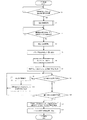
図6A、図6B、図6C及び図6Dは、本発明の一実施形態に係る制御部の制御ロジックを示すフローチャートである。制御部405は以下に示す制御ロジックを実行する。なお、以下の説明においては図2の各構成要素を適宜参照する。
[Control logic of control unit]
6A, 6B, 6C, and 6D are flowcharts illustrating control logic of a control unit according to an embodiment of the present invention. The
まずステップS1において、制御部405は、着座検知センサ404からの着座検知信号を受信したか否かを判定する(S1)。着座検知信号を受信していない場合(S1でNO)、着座検知信号を受信するまでステップS1の処理を繰り返す。
First, in step S1, the
制御部405は、着座検知信号を受信した場合(S1でYES)、ステップS2に進み、図6Bに示す温水準備制御を開始し、未使用中に衛生洗浄装置100の流路20内に滞留する冷水排出を行う。すなわち図6BのステップS21に進み、電磁弁431、熱交換器ユニット440、流量切替弁471及び流路切替弁472を制御し、ノズル473の全ての吐水孔474a、474b、474cより吐水を開始するとともに、流路20内の洗浄水の昇温を開始する(S21)。
When the seating detection signal is received (YES in S1), the
続いてステップS22に進み、制御部405は、所定の温水温度(例えば設定値である30度)へ到達したか否かを判定する(S22)。所定の温水温度に到達していない場合(S22でNO)、続いてステップS23に進み、制御部405は、所定の温水準備時間(例えば設定値である12秒)が経過したか否かを判定する(S23)。所定の温水準備時間が経過していない場合(S23でNO)、ステップS22の処理およびステップS23の処理を繰り返す。
Then, it progresses to step S22 and the
制御部405は、所定の温水温度へ到達した場合(S22でYES)、もしくは所定の温水準備時間が経過した場合(S23でYES)、ステップS24に進み、電磁弁431、熱交換器ユニット440、流量切替弁471及び流路切替弁472を制御し、ステップS21で開始した全ての吐水孔474a、474b、474cからの吐水及び流路20内の流体の昇温を停止する(S24)。
When the predetermined hot water temperature is reached (YES in S22), or when the predetermined hot water preparation time has elapsed (YES in S23), the
図6Aに戻りステップS3に進み、制御部405は、着座検知センサ404からの着座検知信号を受信したか否かを判定するとともに、操作部500により洗浄開始の指示があったか否かを判定する(S3)。着座検知信号を受信しない場合、あるいは洗浄開始の指示がない場合(S5でNO)、着座検知信号を受信し且つ洗浄開始の指示があるという条件、すなわち洗浄開始条件を満たすまでステップS3の処理を繰り返す。
Returning to FIG. 6A and proceeding to step S3, the
洗浄開始条件を満たした場合(S3でYES)、着座検知センサ404からの着座検知信号を受信後から、操作部500より洗浄開始の指示が行われるまでに低下した衛生洗浄装置100の流路20内に滞留する冷水排出を行うため、制御部405は、再び温水準備制御処理(S4)を行う。
When the cleaning start condition is satisfied (YES in S3), the
制御部405は、温水準備制御処理(S4)終了後、ステップS5に進み、ノズル473を規定の進出位置まで進出させる(S5)。ステップS5では、制御部405からの指令に基づいて動作するノズルモータ476が、図1に示すように、ノズル473をボウル801内に進出させる。
After the hot water preparation control process (S4) ends, the
続いてステップS6に進み、制御部405は、図6Cに示すソフトスタート制御処理を行う。図6CのステップS31では、制御部405は、電磁弁431、熱交換器ユニット440、流量切替弁471及び流路切替弁472を制御し、ノズル473が有する吐水孔474a、474b、474cのうちの特定の吐水孔(例えば吐水孔474c)から、規定の瞬間流量以下の瞬間流量で吐水を行うとともに、その他の吐水孔(例えば吐水孔474b)からも少量の瞬間流量で吐水を行う(S31)。
In step S6, the
続いてステップS32に進み、制御部405は、所定のソフトスタート時間(例えば設定値である1秒)が経過したか否かを判定する(S32)。所定のソフトスタート時間が経過していない場合(S32でNO)、ステップS32の処理を繰り返す。
Subsequently, the process proceeds to step S32, and the
すなわち、ステップS32では、制御部405は、吐水孔474a、474b、474cのうちの特定の吐水孔から吐水を開始させる際に、特定の吐水孔からの流量が規定の瞬間流量になるまでの所定時間の間、その他の吐水孔からも少量の吐水を行っている。このように、特定の吐水孔のソフトスタート時にその他の吐水孔からも吐水を行うことによって、両吐水孔から冷水が排出された状態となる。そのため、後に使用者が吐水孔をその他の吐水孔に切り替えた場合であっても、使用者は冷感を感じることがない。したがって、衛生洗浄装置100を快適に使用することができる。
That is, in step S32, when the
なお、本実施形態では、衛生洗浄装置100が三つの吐水孔474a、474b、474cを有する場合について説明したが、この場合には限らない。例えば衛生洗浄装置100が二つの吐水孔を有する場合には、ステップS32では、いずれか一方の特定の吐水孔(第一の吐水孔)から吐水を開始させる際に、他方の吐水孔(第二の吐水孔)からも所定時間吐水を行う。
In addition, although this embodiment demonstrated the case where the
また、特定の吐水孔からは規定の瞬間流量以下の流量で上記所定時間の間吐水を行うとともに、その他の吐水孔からは使用者に着水しない程度の少量の流量で吐水を行うことが好ましい。このように、ソフトスタート中にその他の吐水孔からも使用者が感じることのない吐水を行うことによって、その他の吐水孔に導く流路内に滞留する洗浄水の温度を上げることができる。これにより、吐水孔をその他の吐水孔に切り替えた場合であっても、使用者に冷感を与えることを防ぐことができる。 Further, it is preferable to discharge water from a specific water discharge hole at a flow rate equal to or less than a predetermined instantaneous flow rate for the predetermined time, and to discharge water from the other water discharge holes at a small flow rate that does not reach the user. . In this way, by performing water discharge that is not felt by the user from other water discharge holes during the soft start, the temperature of the cleaning water staying in the flow path leading to the other water discharge holes can be increased. Thereby, even if it is a case where a water discharge hole is switched to another water discharge hole, it can prevent giving a cool feeling to a user.
さらに、特定の吐水孔へ供給する洗浄水の瞬間流量と、その他の吐水孔へ供給する洗浄水の瞬間流量の総和は一定であることが好ましい。これにより、熱交換器ユニット440を通過する瞬間流量が一定となることで、熱交換器ユニット440によって加熱される洗浄水の温度を安定させることができる。
Furthermore, it is preferable that the sum total of the instantaneous flow rate of the cleaning water supplied to the specific water discharge hole and the instantaneous flow rate of the cleaning water supplied to the other water discharge holes is constant. Thereby, the temperature of the wash water heated by the
また、特定の吐水孔へ供給する洗浄水の瞬間流量と、その他の吐水孔へ供給する洗浄水の瞬間流量の総和が局部洗浄(本洗浄)の設定流量と略同一とする。このような構成により、ソフトスタート制御から局部洗浄へ移行した際にも、熱交換器ユニット440を通過する瞬間流量が一定となることで、熱交換器ユニット440によって加熱される洗浄水の温度を安定させることができる。
Further, the sum of the instantaneous flow rate of the cleaning water supplied to the specific water discharge hole and the instantaneous flow rate of the cleaning water supplied to the other water discharge holes is substantially the same as the set flow rate of the local cleaning (main cleaning). With such a configuration, even when shifting from soft start control to local cleaning, the instantaneous flow rate passing through the
制御部405は、所定のソフトスタート時間が経過した場合(S32でYES)、ステップS33に進み、流量切替弁471及び流路切替弁472を制御し、その他の吐水孔からの吐水を停止する(S33)。
When the predetermined soft start time has elapsed (YES in S32), the
その後ステップS34に進み、制御部405は、流量切替弁471及び流路切替弁472を制御し、特定の吐水孔からの瞬間流量を所定の流量分増加させる。(S34)。このとき、増加させる流量は、本洗浄時の水勢調整において、1段階の水勢調整に費やす洗浄水の流量変化量と略同一であることが好ましい。
Thereafter, the process proceeds to step S34, and the
続いてステップS35に進み、制御部405は、特定の吐水孔からの瞬間流量が設定流量まで到達したか否かを判定する(S35)。ここで設定流量とは、使用者が設定している洗浄の水勢に対応した流量、ないしは衛生洗浄装置が予め設定している標準水勢に対応した流量を示す。特定の吐水孔からの瞬間流量が設定流量まで到達していない場合(S35でNO)、ステップS34からの処理を繰り返す。
Then, it progresses to step S35 and the
制御部405は、ステップS35において特定の吐水孔からの瞬間流量が設定流量まで到達した場合(S35でYES)、ソフトスタート制御を終了し、特定の吐水孔のみから一定の設定瞬間流量で吐水を継続する(S7)。
When the instantaneous flow rate from the specific water discharge hole reaches the set flow rate in step S35 (YES in S35), the
その後ステップS8に進み、制御部405は、操作部500により吐水孔の切替指示があったか否かを判定する(S8)。吐水孔の切替指示がない場合(S8でNO)、制御部405は、操作部500により洗浄終了の指示があったか否かを判定する(S10)。洗浄終了の指示がない場合(S10でNO)、洗浄終了の指示があるまでステップS8及びS10の処理を繰り返す。
Thereafter, the process proceeds to step S8, and the
制御部405は、ステップS8において吐水孔の切替指示があった場合(S8でYES)、ステップS9、すなわち図6DのステップS41に進み、ノズル473の位置を微調整する(S41)。ステップS41では、例えば図1に示す衛生洗浄装置100において吐水孔474cから吐水孔474bに切り替える場合、吐水孔474bが吐水孔474cの位置に配置されるように、ノズル473を少し後退させる。またステップS41では、ロータ700(図3参照)を回転させて、吐水孔474bから吐水が行われるよう切り替える。
When there is an instruction to switch the water discharge hole in step S8 (YES in S8), the
その後ステップS42に進み、電磁弁431、熱交換器ユニット440、流量切替弁471及び流路切替弁472を制御し、ノズル473が有する吐水孔474a、474b、474cのうちの切替後の吐水孔(例えば吐水孔474b)から、規定の瞬間流量以下の瞬間流量で吐水を行うとともに、その他の吐水孔(例えば切替前の吐水孔474c)からも少量の瞬間流量で吐水を行う。(S42)。このステップS42以降の制御は、切替後の吐水孔におけるソフトスタートであり、ステップS43〜S46の処理は各々図6CのステップS32〜S35と同様であるとして説明を省略する。
Thereafter, the process proceeds to step S42, where the
なお、以上のステップS41及びS42に示すように、吐水孔を切り替える際に、切替前の吐水孔からの吐水を停止させた後、ノズル473の位置を微調整し、その後切替後の吐水孔からの吐水を開始させている。すなわち、ノズル473を一旦ボウル801外まで後退させるような動作をさせていない。これにより、着水位置の変化による違和感を使用者に与えることを防ぐことができる。
In addition, as shown in the above steps S41 and S42, when switching the water discharge hole, after stopping the water discharge from the water discharge hole before switching, finely adjust the position of the
切替後の吐水孔におけるソフトスタート処理終了後、続いてステップS11に進み、制御部405は、切替後の吐水孔のみから規定の瞬間流量で吐水を行う(S11)。
After the soft start process at the water discharge hole after switching is completed, the process proceeds to step S11, and the
制御部405は、操作部500により洗浄終了の指示があった場合(S10)、ステップS12に進み、電磁弁431を制御し、吐水を停止すると共に流路20内の洗浄水の昇温を停止する(S12)。
When the
続いてステップS13に進み、制御部405は、ノズル473を規定の待機位置に後退させる(S13)。ステップS13では、制御部405からの指令に基づいて動作するノズルモータ476が、ノズル473をボウル801内から後退させる。
Then, it progresses to step S13 and the
以上に示す処理により、本実施形態に係る制御部405は、吐水孔の切替並びに吐水孔からの吐水を制御する。
Through the processing described above, the
[具体例]
続いて、図6A〜図6Dの処理の具体例を説明する。図7は、本発明の一実施形態に係る制御部の制御ロジックを実行した具体例に係るタイムチャートである。図7では、横軸に時間を、縦軸に水温を示している。また、図8〜図13は、本発明の一実施形態に係る衛生洗浄装置における吐水を説明するための図である。
[Concrete example]
Subsequently, a specific example of the processing of FIGS. 6A to 6D will be described. FIG. 7 is a time chart according to a specific example in which the control logic of the control unit according to the embodiment of the present invention is executed. In FIG. 7, the horizontal axis represents time, and the vertical axis represents water temperature. Moreover, FIGS. 8-13 is a figure for demonstrating the water discharge in the sanitary washing apparatus which concerns on one Embodiment of this invention.
なお、本具体例では、まず吐水孔474cから吐水させ、その後吐水孔を吐水孔474cから吐水孔474bに切り替える動作を説明する。
In this specific example, the operation of first discharging water from the
時刻T0において、制御部405は着座検知センサからの着座検知信号を受信し(S1でYES)、温水準備制御を開始する(S2)。
At time T0, the
図8(a)は、時刻T0におけるステータ600とロータ700との位置関係を示している。図8(a)ではステータ600を点線で、ロータ700を実線で示している(図9〜図13についても同様)。
FIG. 8A shows the positional relationship between the
図8(a)に示すように、ロータ700の切欠部704は、第一吐水流路用孔601に通じる窪み部611と連通している。ロータ700の貫通孔702は、第二吐水流路用孔602に通じる窪み部612aと連通している。ロータ700の貫通孔703は、第三吐水流路用孔603の一つである貫通孔603cと連通している。これにより、全ての吐水流路用孔601、602、603においてステータ600とロータ700とは連通している。
As shown in FIG. 8A, the
そのため、図8(b)に示すように、全ての吐水孔474a、474b、474cから吐水が行われる。なお、図7に示すように、時刻T0〜T1の間に吐水孔474a、474b、474cから吐水される洗浄水の温度は30度まで上昇する。また、図7に示す具体例中では、時刻T0〜T1区間中に操作部500からの洗浄開始指示を受けるとともに、着座検知信号の受信が継続しているものとし(S3でYES、S4)、洗浄を開始している。
Therefore, as shown in FIG.8 (b), water discharge is performed from all the
その後、所定の温水準備時間が経過した時刻T1において、制御部405は、ノズル473を規定の進出位置に進出させた上で(S5)、ステップS6の処理、ここでは吐水孔474cのソフトスタートを開始する(S6)。
After that, at time T1 when a predetermined warm water preparation time has elapsed, the
図9(a)は、時刻T1におけるステータ600とロータ700との位置関係を示している。図9(a)に示すように、ロータ700の貫通孔701は、第二吐水流路用孔602に通じる窪み部612aと連通している。ロータ700の切欠部704は、第三吐水流路用孔603の一つである貫通孔603aに通じる窪み部613と連通している。これにより、第二吐水流路用孔602と第三吐水流路用吐水孔603においてステータ600とロータ700とは連通している。
FIG. 9A shows the positional relationship between the
そのため、図9(b)に示すように、第二吐水孔474b、第三吐水孔474cの二つの吐水孔から吐水が行われる。なお、第三吐水孔474cからの吐水流量が第二吐水孔474bからの吐水流量よりも大きく、特に第二吐水孔474bからの吐水流量は使用者に着水しない程度の流量である。そのため、使用者は、第二吐水孔474bからの吐水を意識することなく衛生洗浄装置100を使用することができる。また、図7に示すように、時刻T1〜T2の間に第二吐水孔474b、第三吐水孔474cから吐水される洗浄水の温度は35度まで上昇する。所定の時間が経過すると(S32)、制御部405は、ロータ700を回動させる。これにより、図9(a)に示すロータ700の切欠部704と、第三吐水流路用孔603の一つである貫通孔603aに通じる窪み部613との連通は保持されたまま、ロータ700の貫通孔701と、第二吐水流路用孔602に通じる窪み部612aとの連通が解除され、第二吐水孔474bからの吐水が停止する。
Therefore, as shown in FIG. 9B, water is discharged from the two water discharge holes, the second
制御部405は、ロータ700をさらに回動させることにより、図9(a)に示すロータ700の切欠部704と、第三吐水流路用孔603の一つである貫通孔603aに通じる窪み部613との連通によって形成される流路断面積が変化し、第三吐水孔474cより吐水される洗浄水の瞬間流量が増加する(S34)。
The
その後時刻T2において、制御部405は、ソフトスタート処理を終了し(S35でYES)、ステップS7の処理、ここでは吐水孔474cによる本洗浄を開始する(S7)。
Thereafter, at time T2, the
図10(a)は、時刻T2におけるステータ600とロータ700との位置関係を示している。図10(a)に示すように、ロータ700の切欠部704は、第三吐水流路用孔603の一つである貫通孔603aに通じる窪み部613と連通している。すなわち、第三吐水流路用孔603のみにおいてステータ600とロータ700とは連通している。
FIG. 10A shows the positional relationship between the
そのため、図10(b)に示すように、第三吐水孔474cのみにおいて吐水が行われる。なお、図7に示すように、時刻T2〜T3の間に第三吐水孔474cから吐水される洗浄水の温度は40度まで上昇する。
Therefore, as shown in FIG.10 (b), water discharge is performed only in the 3rd
その後時刻T3において、制御部405は、ステップS7の処理の途中に、吐水孔を吐水孔474bに切り替える指示を受信し(S8でYES)、ノズル473の位置を微調整する(S41)。
Thereafter, at time T3, the
図11(a)は、時刻T3におけるステータ600とロータ700との位置関係を示している。図11(a)に示すように、ロータ700の切欠部704は、ステータ600のバイパス流路用孔604と連通している。すなわち、バイパス流路用孔604のみにおいてステータ600とロータ700とは連通している。
FIG. 11A shows the positional relationship between the
そのため、図11(b)に示すように、各吐水孔474a、474b、474cからの吐水は行われない。なお、時刻T3〜時刻T4において、ノズル473の位置の微調整等に要する時間は2秒間以下であることが好ましく、約0.5秒以下であることがさらに好ましい(S21)。
Therefore, as shown in FIG.11 (b), the water discharge from each
その後時刻T4において、制御部405は、ステップS9の処理、ここでは吐水孔474bのソフトスタートを開始する(S42〜S46)。
Thereafter, at time T4, the
図12(a)は、時刻T4におけるステータ600とロータ700との位置関係を示している。図12(a)に示すように、ロータ700の切欠部704は、第二吐水流路用孔602に通じる窪み部612と連通している。ロータ700の貫通孔702は、第三吐水流路用孔603の一つである貫通孔603bと連通している。これにより、第二吐水流路用孔602と第三吐水流路用吐水孔603においてステータ600とロータ700とは連通している。
FIG. 12A shows the positional relationship between the
そのため、図12(b)に示すように、第二吐水孔474b、第三吐水孔474cの二つの吐水孔から吐水が行われる。なお、第二吐水孔474bからの吐水流量が第三吐水孔474cからの吐水流量よりも大きく、特に第三吐水孔474cからの吐水流量は使用者に着水しない程度の流量である。そのため、使用者は、第三吐水孔474cからの吐水を意識することなく衛生洗浄装置100を使用することができる。
Therefore, as shown in FIG.12 (b), water discharge is performed from two water discharge holes, the 2nd
その後時刻T5において、制御部405は、切替後の吐水孔におけるソフトスタート処理を終了し、ステップS11の処理、ここでは吐水孔474bによる本洗浄を開始する(S11)。
Thereafter, at time T5, the
図13(a)は、時刻T5におけるステータ600とロータ700との位置関係を示している。図13(a)に示すように、ロータ700の切欠部704は、第二吐水流路用孔602に通じる窪み部612と連通している。すなわち、第二吐水流路用孔602のみにおいてステータ600とロータ700とは連通している。
FIG. 13A shows the positional relationship between the
そのため、図13(b)に示すように、第二吐水孔474bのみにおいて吐水が行われる。なお、図7に示すように、時刻T5〜T6の間に第二吐水孔474bから吐水される洗浄水の温度は40度まで上昇する。
Therefore, as shown in FIG.13 (b), water discharge is performed only in the 2nd
以上に示すように、本具体例では、まず第三吐水孔474cから吐水させ、その後吐水孔を第二吐水孔474bに切り替える。その際、図7に示すように、第三吐水孔474cのソフトスタート時に第二吐水孔474bからも吐水を行うことによって、第二吐水孔474bから吐水される洗浄水の温度を従来よりも上昇させている。そのため、吐水孔を第三吐水孔474cから第二吐水孔474bに切り替えた場合であっても、使用者に冷感を与えることがなく、快適なトイレ装置1を提供することができる。
As described above, in this specific example, water is first discharged from the third
以上、本発明の実施形態について説明したが、上記実施形態は本発明の適用例の一つを示したものであり、本発明の技術的範囲を上記実施形態の具体的構成に限定する趣旨ではない。本発明の要旨を逸脱しない範囲において種々変更可能である。 As mentioned above, although embodiment of this invention was described, the said embodiment showed one of the application examples of this invention, and in the meaning which limits the technical scope of this invention to the specific structure of the said embodiment. Absent. Various modifications can be made without departing from the scope of the present invention.
1 トイレ装置
20 流路
20a 第一吐水流路
20b 第二吐水流路
20c 第三吐水流路
100 衛生洗浄装置
405 制御部
440 熱交換器ユニット
473 ノズル
474a 第一吐水孔
474b 第二吐水孔
474c 第三吐水孔
800 便器
DESCRIPTION OF SYMBOLS 1
Claims (5)
前記ノズルへ洗浄水を供給する流路と、
前記流路に設けられ、洗浄水を所定の温度まで昇温させる熱交換器と、
前記第一の吐水孔及び前記第二の吐水孔への洗浄水の供給を制御する制御部と、
を備えた衛生洗浄装置であって、
前記制御部は、前記ノズルをボウル内に進出させ、前記第一の吐水孔から吐水される洗浄水の水量を漸増させる制御中に、前記第一の吐水孔から、該第一の吐水孔からの流量が規定の瞬間流量になるまでの所定時間の間吐水させると共に、前記第二の吐水孔から、前記規定の瞬間流量より少量であって使用者に着水しない流量で吐水させることを特徴とする衛生洗浄装置。 A nozzle having a first water discharge hole and a second water discharge hole for discharging washing water to a human body local part ;
A flow path for supplying cleaning water to the nozzle;
A heat exchanger provided in the flow path for raising the temperature of the washing water to a predetermined temperature;
A control unit for controlling the supply of washing water to the first water discharge hole and the second water discharge hole;
A sanitary washing device comprising:
Wherein the control unit, the nozzle is advanced into the bowl, said in control to gradually increase the first amount of water of water jetted hole or al spouting, from said first jetting port, said first water discharge port Water is discharged for a predetermined time until the flow rate from the specified instantaneous flow rate becomes a predetermined flow rate, and is discharged from the second water discharge hole at a flow rate that is smaller than the specified instantaneous flow rate and does not reach the user. Characteristic sanitary washing device.
Priority Applications (1)
| Application Number | Priority Date | Filing Date | Title |
|---|---|---|---|
| JP2013125859A JP6111884B2 (en) | 2013-06-14 | 2013-06-14 | Sanitary washing device and toilet device |
Applications Claiming Priority (1)
| Application Number | Priority Date | Filing Date | Title |
|---|---|---|---|
| JP2013125859A JP6111884B2 (en) | 2013-06-14 | 2013-06-14 | Sanitary washing device and toilet device |
Publications (3)
| Publication Number | Publication Date |
|---|---|
| JP2015001095A JP2015001095A (en) | 2015-01-05 |
| JP2015001095A5 JP2015001095A5 (en) | 2016-04-28 |
| JP6111884B2 true JP6111884B2 (en) | 2017-04-12 |
Family
ID=52295783
Family Applications (1)
| Application Number | Title | Priority Date | Filing Date |
|---|---|---|---|
| JP2013125859A Expired - Fee Related JP6111884B2 (en) | 2013-06-14 | 2013-06-14 | Sanitary washing device and toilet device |
Country Status (1)
| Country | Link |
|---|---|
| JP (1) | JP6111884B2 (en) |
Families Citing this family (1)
| Publication number | Priority date | Publication date | Assignee | Title |
|---|---|---|---|---|
| JP6748943B2 (en) * | 2016-08-22 | 2020-09-02 | Toto株式会社 | Sanitary washing equipment |
Family Cites Families (1)
| Publication number | Priority date | Publication date | Assignee | Title |
|---|---|---|---|---|
| JPH09144104A (en) * | 1995-11-27 | 1997-06-03 | Toto Ltd | Part washing device |
-
2013
- 2013-06-14 JP JP2013125859A patent/JP6111884B2/en not_active Expired - Fee Related
Also Published As
| Publication number | Publication date |
|---|---|
| JP2015001095A (en) | 2015-01-05 |
Similar Documents
| Publication | Publication Date | Title |
|---|---|---|
| JP6765644B1 (en) | Sanitary cleaning equipment | |
| KR20200143231A (en) | Sanitary washing apparatus | |
| JP2009281139A (en) | Human body washing device | |
| JP6111884B2 (en) | Sanitary washing device and toilet device | |
| JP6288546B2 (en) | Sanitary washing device | |
| JP2009119057A (en) | Mist sauna device and mist sauna system equipped with the same | |
| JP6153082B2 (en) | Sanitary washing device | |
| JP3199817U (en) | Cleaning device | |
| JPH0358007B2 (en) | ||
| JP2004263423A (en) | Toilet device | |
| JP4586947B2 (en) | Human body cleaning device | |
| JPH1060981A (en) | Hot water temperature control device for sanitary washing device | |
| JP2011144568A (en) | Hygienic washing apparatus | |
| JP2001227035A (en) | Control method of hot water cleaning device | |
| JP5603159B2 (en) | Water supply equipment | |
| JP4172766B2 (en) | Sanitary washing device | |
| JP3200922B2 (en) | Hot water cleaning equipment | |
| JPH0215209B2 (en) | ||
| JP2000204637A (en) | Human body cleaning device | |
| JP3200104U (en) | Bathroom heating unit | |
| JP3973972B2 (en) | Human body local cleaning equipment | |
| JP4186491B2 (en) | Toilet equipment | |
| JP2000328630A (en) | Human body washing equipment | |
| JP6268878B2 (en) | Sanitary washing device | |
| JP2020204155A (en) | Sanitary washing device |
Legal Events
| Date | Code | Title | Description |
|---|---|---|---|
| A521 | Request for written amendment filed |
Free format text: JAPANESE INTERMEDIATE CODE: A523 Effective date: 20160311 |
|
| A621 | Written request for application examination |
Free format text: JAPANESE INTERMEDIATE CODE: A621 Effective date: 20160311 |
|
| A131 | Notification of reasons for refusal |
Free format text: JAPANESE INTERMEDIATE CODE: A131 Effective date: 20160809 |
|
| A521 | Request for written amendment filed |
Free format text: JAPANESE INTERMEDIATE CODE: A523 Effective date: 20160929 |
|
| TRDD | Decision of grant or rejection written | ||
| A01 | Written decision to grant a patent or to grant a registration (utility model) |
Free format text: JAPANESE INTERMEDIATE CODE: A01 Effective date: 20170214 |
|
| A61 | First payment of annual fees (during grant procedure) |
Free format text: JAPANESE INTERMEDIATE CODE: A61 Effective date: 20170227 |
|
| R150 | Certificate of patent or registration of utility model |
Ref document number: 6111884 Country of ref document: JP Free format text: JAPANESE INTERMEDIATE CODE: R150 |
|
| LAPS | Cancellation because of no payment of annual fees |