JP6110550B1 - Hose fittings - Google Patents
Hose fittings Download PDFInfo
- Publication number
- JP6110550B1 JP6110550B1 JP2016160283A JP2016160283A JP6110550B1 JP 6110550 B1 JP6110550 B1 JP 6110550B1 JP 2016160283 A JP2016160283 A JP 2016160283A JP 2016160283 A JP2016160283 A JP 2016160283A JP 6110550 B1 JP6110550 B1 JP 6110550B1
- Authority
- JP
- Japan
- Prior art keywords
- engagement
- discharge pipe
- upper member
- lower member
- ring
- Prior art date
- Legal status (The legal status is an assumption and is not a legal conclusion. Google has not performed a legal analysis and makes no representation as to the accuracy of the status listed.)
- Active
Links
- 238000012856 packing Methods 0.000 claims abstract description 55
- 238000003780 insertion Methods 0.000 claims abstract description 30
- 230000037431 insertion Effects 0.000 claims abstract description 30
- 238000003825 pressing Methods 0.000 claims abstract description 16
- 238000000034 method Methods 0.000 description 42
- XLYOFNOQVPJJNP-UHFFFAOYSA-N water Substances O XLYOFNOQVPJJNP-UHFFFAOYSA-N 0.000 description 34
- 210000000078 claw Anatomy 0.000 description 33
- 229920005989 resin Polymers 0.000 description 28
- 239000011347 resin Substances 0.000 description 28
- 230000008878 coupling Effects 0.000 description 21
- 238000010168 coupling process Methods 0.000 description 21
- 238000005859 coupling reaction Methods 0.000 description 21
- 229920006324 polyoxymethylene Polymers 0.000 description 21
- XECAHXYUAAWDEL-UHFFFAOYSA-N acrylonitrile butadiene styrene Chemical compound C=CC=C.C=CC#N.C=CC1=CC=CC=C1 XECAHXYUAAWDEL-UHFFFAOYSA-N 0.000 description 18
- 229920000122 acrylonitrile butadiene styrene Polymers 0.000 description 18
- 239000004676 acrylonitrile butadiene styrene Substances 0.000 description 18
- 230000000694 effects Effects 0.000 description 18
- 210000002445 nipple Anatomy 0.000 description 14
- 238000000465 moulding Methods 0.000 description 13
- 239000004743 Polypropylene Substances 0.000 description 12
- 239000000463 material Substances 0.000 description 12
- 229920001155 polypropylene Polymers 0.000 description 12
- 230000005489 elastic deformation Effects 0.000 description 11
- 230000001965 increasing effect Effects 0.000 description 11
- 229930182556 Polyacetal Natural products 0.000 description 10
- 230000007246 mechanism Effects 0.000 description 7
- 230000008859 change Effects 0.000 description 6
- -1 polypropylene Polymers 0.000 description 6
- 229920005992 thermoplastic resin Polymers 0.000 description 6
- 238000009434 installation Methods 0.000 description 5
- 239000002184 metal Substances 0.000 description 5
- 230000002265 prevention Effects 0.000 description 5
- 230000006870 function Effects 0.000 description 4
- 238000005452 bending Methods 0.000 description 3
- 230000015572 biosynthetic process Effects 0.000 description 3
- 230000008569 process Effects 0.000 description 3
- 238000000926 separation method Methods 0.000 description 3
- 238000003466 welding Methods 0.000 description 3
- 238000013459 approach Methods 0.000 description 2
- 230000004323 axial length Effects 0.000 description 2
- 230000006835 compression Effects 0.000 description 2
- 238000007906 compression Methods 0.000 description 2
- 238000012423 maintenance Methods 0.000 description 2
- 238000004519 manufacturing process Methods 0.000 description 2
- 230000002093 peripheral effect Effects 0.000 description 2
- 238000013519 translation Methods 0.000 description 2
- 238000006073 displacement reaction Methods 0.000 description 1
- 230000003670 easy-to-clean Effects 0.000 description 1
- 230000002708 enhancing effect Effects 0.000 description 1
- 238000012545 processing Methods 0.000 description 1
- 230000009467 reduction Effects 0.000 description 1
- 230000001105 regulatory effect Effects 0.000 description 1
Images


Abstract
【課題】利便性に優れたホース接続具の提供。【解決手段】ホース接続具100は、互いに取り外し可能に接続されうる上側部材200及び下側部材300を有している。上側部材200は、蛇口の排出管f3に上側から当接しうる当接部210と、上側係合部220とを有している。下側部材300は、パッキン312を有する排出管挿入部302と、上側係合部220と係合しうる下側係合部304と、ホース接続部306と、を有している。上側係合部220と下側係合部304とが互いに係合した接続状態により、曲がって延びる排出管f3を挟み込むことができる。上側部材200及び下側部材300のうちの一方を他方に対して押し付けることにより、前記接続状態が形成される。【選択図】図3To provide a hose connector excellent in convenience. A hose connector 100 includes an upper member 200 and a lower member 300 that can be detachably connected to each other. The upper member 200 includes an abutting portion 210 that can abut on the faucet discharge pipe f3 from above and an upper engaging portion 220. The lower member 300 includes a discharge pipe insertion portion 302 having a packing 312, a lower engagement portion 304 that can be engaged with the upper engagement portion 220, and a hose connection portion 306. Due to the connection state in which the upper engagement portion 220 and the lower engagement portion 304 are engaged with each other, the bent discharge pipe f3 can be sandwiched. The connection state is formed by pressing one of the upper member 200 and the lower member 300 against the other. [Selection] Figure 3
Description
本発明は、蛇口にホースを接続するためのホース接続具に関する。 The present invention relates to a hose connector for connecting a hose to a faucet.
蛇口にホースを接続しうるホース接続具が知られている。特開昭56−105191号公報は、固定用のねじを有するホース継手を開示する。このホース継手は、周方向に分散して配置された複数のねじを締め付けることによって、蛇口に固定される。ねじの締め付けには、手間がかかる。更に、複数のねじを均等に締め付けるのには、多くの時間と労力とを必要とする。 A hose connector that can connect a hose to a faucet is known. Japanese Patent Application Laid-Open No. 56-105191 discloses a hose joint having a fixing screw. The hose joint is fixed to the faucet by tightening a plurality of screws arranged in a circumferential direction. It takes time to tighten the screws. Furthermore, it takes a lot of time and effort to evenly tighten the screws.
これに対して、上述したような複数のねじの締め付けが不要なホース接続部が提案されている。特表2007−528458号公報は、下部にねじ部が形成された固定具と、前記固定具の内部に嵌入される接続具と、前記固定部のねじ部と締結されるねじ部を有する締結部と、を有する蛇口接続用カップリングを開示する。 On the other hand, a hose connection part that does not require tightening of a plurality of screws as described above has been proposed. Japanese translation of PCT publication No. 2007-528458 discloses a fastener having a screw part formed at a lower part thereof, a connecting tool fitted inside the fixture, and a fastening part having a screw part fastened to the screw part of the fixed part. And a tap connection coupling.
本発明者は、利便性に優れたホース接続具について鋭意検討を行った。その結果、装着容易性が高く、更に他の利便性も備えたホース接続具を想到するに至った。 This inventor earnestly examined about the hose connector excellent in convenience. As a result, the present inventors have come up with a hose connector that is easy to attach and has other conveniences.
本発明の目的は、利便性に優れたホース接続具の提供にある。 An object of the present invention is to provide a hose connector excellent in convenience.
好ましいホース接続具は、互いに取り外し可能に接続されうる上側部材及び下側部材を有している。前記上側部材が、蛇口の排出管に上側から当接しうる当接部と、上側係合部とを有している。前記下側部材が、パッキンを有する排出管挿入部と、前記上側係合部と係合しうる下側係合部と、ホース接続部と、を有している。前記上側係合部と前記下側係合部とが互いに係合した接続状態により、曲がって延びる前記排出管を挟み込むことができる。前記上側部材及び前記下側部材のうちの一方を他方に対して押し付けることにより、前記接続状態が形成される。 A preferred hose connector has an upper member and a lower member that can be removably connected to each other. The upper member has a contact portion that can contact the discharge pipe of the faucet from above and an upper engagement portion. The lower member includes a discharge pipe insertion portion having packing, a lower engagement portion that can be engaged with the upper engagement portion, and a hose connection portion. Due to the connection state in which the upper engagement portion and the lower engagement portion are engaged with each other, the bent and extended discharge pipe can be sandwiched. The connection state is formed by pressing one of the upper member and the lower member against the other.
好ましくは、前記上側係合部が、周方向における一部が欠落した欠落部を有している。 Preferably, the upper engaging portion has a missing portion in which a part in the circumferential direction is missing.
好ましくは、前記欠落部が周方向における2箇所に設けられることで、前記上側係合部が第1係合部と第2係合部とに分断されている。好ましくは、前記上側部材が、前記第1係合部と前記第2係合部とを繋ぐ連結部を有している。好ましくは、前記連結部が、前記当接部を有している。 Preferably, the missing portion is provided at two locations in the circumferential direction, so that the upper engagement portion is divided into a first engagement portion and a second engagement portion. Preferably, the upper member includes a connecting portion that connects the first engaging portion and the second engaging portion. Preferably, the connection part has the contact part.
好ましくは、前記パッキンが、前記排出管の外面に密着しうる円筒部を有している。好ましくは、前記円筒部の外側に空間が設けられている。 Preferably, the packing has a cylindrical portion that can be in close contact with the outer surface of the discharge pipe. Preferably, a space is provided outside the cylindrical portion.
好ましくは、前記上側部材が、上側から前記排出管に取り付けることができる。 Preferably, the upper member can be attached to the discharge pipe from above.
好ましい他のホース接続具は、互いに取り外し可能に接続されうる上側部材及び下側部材を有している。前記上側部材は、蛇口の排出管に上側から当接しうる当接部と、上側係合部とを有している。前記下側部材が、パッキンを有する排出管挿入部と、前記上側係合部と係合しうる下側係合部と、ホース接続部と、を有している。前記上側係合部と前記下側係合部とが互いに係合した接続状態により、曲がって延びる前記排出管を挟み込むことができる。前記接続状態において、前記上側部材が、前記パッキンに圧縮力を付与していない。 Another preferred hose connector has an upper member and a lower member that can be removably connected to each other. The upper member has a contact portion that can contact the discharge pipe of the faucet from above and an upper engagement portion. The lower member includes a discharge pipe insertion portion having packing, a lower engagement portion that can be engaged with the upper engagement portion, and a hose connection portion. Due to the connection state in which the upper engagement portion and the lower engagement portion are engaged with each other, the bent and extended discharge pipe can be sandwiched. In the connected state, the upper member does not apply a compressive force to the packing.
好ましくは、前記下側係合部が、有端の環状部材であるリング係合体によって構成されている。好ましくは、前記リング係合体が、係合突出部を有している。好ましくは、前記上側部材が、前記上側係合部としての凹部と、当接面を有している。好ましくは、前記下側部材が、貫通孔を有している。好ましくは、前記リング係合体が正規装着状態にあるとき、前記係合突出部が前記貫通孔を通過して前記下側部材の内部に突出している。好ましくは、前記当接面が、前記上側部材及び前記下側部材のうちの一方を他方に対して押し付けることにより、前記下側部材の内部に突出する前記係合突出部に当接して前記リング係合体を拡開変形させるように構成されている。好ましくは、前記係合突出部が、前記拡開変形後の前記リング係合体の縮径変形により前記凹部に入り込んでいる。 Preferably, the lower engagement portion is constituted by a ring engagement body that is an end-like annular member. Preferably, the ring engagement body has an engagement protrusion. Preferably, the upper member has a concave portion as the upper engaging portion and a contact surface. Preferably, the lower member has a through hole. Preferably, when the ring engagement body is in a normal mounting state, the engagement protrusion portion passes through the through hole and protrudes into the lower member. Preferably, the abutment surface abuts on the engagement protrusion protruding inside the lower member by pressing one of the upper member and the lower member against the other, and the ring The engaging body is configured to be expanded and deformed. Preferably, the engagement protrusion enters the recess due to a diameter-reducing deformation of the ring engagement body after the expansion deformation.
利便性に優れたホース接続具が得られうる。 A hose connector excellent in convenience can be obtained.
以下、適宜図面が参照されつつ、好ましい実施形態に基づいて本発明が詳細に説明される。 Hereinafter, the present invention will be described in detail based on preferred embodiments with appropriate reference to the drawings.
本願では、典型的な蛇口の姿勢に基づいて、「上」、「上側」、「下」、「下側」等の文言が用いられる。また、この典型的な状況における使用者の視点に基づいて、「右」、「右側」、「左」、「左側」等の文言が用いられる。蛇口の姿勢が非典型的である場合、これらの文言は、当該姿勢に沿って解釈される。 In the present application, words such as “upper”, “upper side”, “lower”, and “lower side” are used based on the posture of a typical faucet. Further, words such as “right”, “right side”, “left”, and “left side” are used based on the viewpoint of the user in this typical situation. If the faucet posture is atypical, these words are interpreted along that posture.
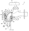
図1は、第1実施形態に係るホース接続具100が水栓f1に装着された状態を示す斜視図である。図2は、図1の断面図である。図3は、図1の分解斜視図である。図4は、図3の下側部材が更に分解された分解斜視図である。
FIG. 1 is a perspective view showing a state in which the
ホース接続具100は、上側部材200と、下側部材300とを有する。上側部材200と下側部材300とは、互いに取り外し可能に接続されている。上側部材200が下側部材300の内側に挿入された状態で、両者が接続される。
The
水栓f1は、水栓本体f2と、排出管f3と、操作部f4とを有する。更に水栓f1には、バルブ(図示されず)が内蔵されている。操作部f4を操作(回転)させることで、吐止水の切替及び吐水量の調整が可能である。 The faucet f1 has a faucet body f2, a discharge pipe f3, and an operation part f4. Further, a valve (not shown) is incorporated in the faucet f1. By operating (rotating) the operation unit f4, it is possible to switch the discharged water and adjust the discharged water amount.
本実施形態において、水栓f1は、水栓本体f2に対して排出管f3が固定されている。当業者において、この水栓f1は、横水栓と称されている。なお、この水栓f1では水栓本体f2と排出管f3との境界が不明である。便宜上、バルブよりも下流側の部分が排出管f3とみなされうる。 In the present embodiment, the faucet f1 has a discharge pipe f3 fixed to the faucet body f2. In those skilled in the art, the faucet f1 is referred to as a horizontal faucet. In this faucet f1, the boundary between the faucet body f2 and the discharge pipe f3 is unknown. For convenience, the portion downstream of the valve can be regarded as the discharge pipe f3.
上側部材200は、全体として一体的に成形された部材である。上側部材200は、全体として、ドーム状構造における周方向の一部が欠落した形状を有する。上側部材200の詳細については、後述される。
The
図3が示すように、下側部材300は、排出管挿入部302と、下側係合部304と、ホース接続部306とを有する。排出管挿入部302は、円筒内面を有している。排出管挿入部302に、排出管f3の下端部が挿入される。ホース接続部306には、ホース(ホースの端に取り付けられたコネクタ)が接続される。
As shown in FIG. 3, the
図4が示すように、排出管挿入部302は、スライドリング308と、本体部310と、パッキン312とを有する。本体部310は、周方向の複数箇所(3箇所)に、開口314を有する。
As shown in FIG. 4, the discharge
下側係合部304は、係合弾性体316を有する。係合弾性体316は、周方向における複数箇所(3箇所)に設けられている。係合弾性体316は、基部317と、この基部317の上端から斜め下方に延びる係合爪318を有する。開口314のそれぞれに、係合弾性体316が配置されている。押圧されていない自然状態では、係合爪318は、開口314から、半径方向内側に突出している。
The
パッキン312は、フランジ部320と円筒部322とを有する。フランジ部320は、円筒部322の上端から、半径方向外側に延びている。円筒部322の内径は、当該円筒部322に挿入される部分における排出管f3の外径よりも小さく設定されている。
The packing 312 has a
図4が示すように、ホース接続部306は、ニップル部材330によって構成されている。ニップル部材330は、ホース接続部306と、ねじ部332とを有する。このねじ部332は、雄ねじである。一方、図2が示すように、本体部310はねじ部340を有する。このねじ部340は雌ねじである。ねじ部332とねじ部340とがねじ結合されている。
As shown in FIG. 4, the
ねじ部332とねじ部340とのねじ結合を利用して、パッキン312が固定されている。具体的には、パッキン312のフランジ部320が、本体部310の内側延在部342とニップル部材330の上端面344とによって挟まれている。上記ねじ結合のねじ込み量を増やすほど、内側延在部342と上端面344とが接近し、フランジ部320が強く挟み込まれる。この構成により、パッキン312は容易に且つ確実に固定されている。
The packing 312 is fixed using the screw connection between the
図3が示すように、下側部材300の排出管挿入部302は、その周方向における一部が欠落した欠落部350を有している。この欠落部350は、スライドリング308の欠落部352及び本体部310の欠落部354によって構成されている(図4参照)。
As shown in FIG. 3, the discharge
図5(a)は、右斜め上方から見た上側部材200の斜視図である。図5(b)は、右斜め下方から見た上側部材200の斜視図である。図5(c)は、左斜め下方から見た上側部材200の斜視図である。図6(a)は、上側部材200の平面図である。図6(b)は、上側部材200の正面図である。図6(c)は、上側部材200の底面図である。図7(a)は、上側部材200の右側面図である。図7(b)は、図6(b)のA−A線に沿った断面図である。図7(c)は、上側部材200の背面図である。
FIG. 5A is a perspective view of the
上側部材200は、側壁部202と、上壁部204とを有する。上側部材200は下方に開放されている。側壁部202は、略円筒形状であるが、その周方向における一部が欠落している。すなわち、側壁部202は欠落部206を有する。
The
上側部材200は、排出管f3に上側から当接しうる当接部210を有する(図2参照)。上側部材200の上壁部204において、欠落部206の上側に位置する部分が、当接部210である。
The
上側部材200は、上側係合部220を有している。上側係合部220は、側壁部202に設けられている。上側係合部220は、凹みである。より詳細には、上側係合部220は、周方向に沿って設けられた溝である。ただし、欠落部206が存在する領域では、上側係合部220(溝)は途切れている。この上側係合部220は、係合弾性体316の係合爪318と係合しうる。
The
[接続状態及び取付状態]
本願では、上側部材200と下側部材300とが互いに係合した状態が、接続状態とも称される。図2が示すように、この接続状態により、曲がって延びる排出管f3が挟み込まれている。この挟み込みにより、ホース接続具100は排出管f3に固定されている。接続状態が維持されている限り、ホース接続具100が排出管f3から抜けることはない。なお、本願において「排出管f3の挟み込み」とは、排出管f3が抜けない状態で保持されていることを意味する。
[Connection state and mounting state]
In the present application, the state in which the
接続状態は、上側部材200及び下側部材300のうちの一方を他方に対して押し付けることにより、形成される。上側部材200を下側部材300に押し付けてもよいし、下側部材300を上側部材200に押し付けても良い。なお、「押し付ける」との文言は、後述される係合弾性体316のような部材(係合が完了するまでの過程で一時的に変形される部材)を変形させるための力を考慮したものである。接続状態を形成するための係合は、上側部材200と下側部材300との間の位置関係が所定の位置関係になると発現する凹凸係合である。上側部材200及び下側部材300のいずれか一方が圧縮による弾性変形により退行する凸部を有し、他方が上記所定の位置関係において前記凸部の突出を許容しつつ当該突出した凸部と係合する凹部を有していれば良い。接続状態は、ワンタッチで形成される。以下、この係合がワンタッチ接続とも称される。接続状態の形成は非常に容易である。
The connection state is formed by pressing one of the
上側部材200と下側部材300との係合は、弾性変形による係合である。本実施形態では、下側部材300の係合弾性体316が弾性変形している。弾性変形する部分は、下側部材300の少なくとも一部であってもよく、上側部材200の少なくとも一部であってもよい。弾性変形による係合により、ワンタッチ接続が達成されている。
The engagement between the
ホース接続具100の取付方法として、次の手順A及び手順Bが可能である。手順A及び手順Bにより、接続状態の完了と同時に、取付状態が完了する。
(手順A)排出管f3に上側部材200を上から被せて、次に、排出管f3を排出管挿入部302に挿入しつつ、下側部材300を下から上側部材200に押し付ける。
(手順B)排出管f3に下側部材300を下から取付けて、次に上側部材200を上から下側部材300に押し付ける。
As a method for attaching the
(Procedure A) The
(Procedure B) The
いずれの手順においても、上側係合部220(凹み)が下側係合部304(係合弾性体316)に係合することで、接続状態が完了する。上側部材200及び下側部材300のいずれか一方が他方に対して押し付けられる過程で、上側部材200の下端部が係合爪318を押圧する。係合爪318は斜め下方に向かって延びているため、上から下に向かって移動する上側部材200により容易に押圧され、半径方向外側に退行する。上側部材200の上側係合部220(凹み)が係合爪318の位置にまで達すると、係合爪318は、押圧から開放され、上側係合部220(凹み)の内側に突出する。この結果、係合爪318と上側係合部220とが係合する。換言すれば、上側係合部220と下側係合部304とが係合する。このように、上側部材200及び下側部材300のうちの一方を他方に対して押し付けるだけで、接続状態を形成することができる。
In any procedure, the connection state is completed when the upper engagement portion 220 (dent) is engaged with the lower engagement portion 304 (engagement elastic body 316). In the process in which one of the
なお、スライドリング308は、上側係合部220(凹み)と下側係合部304(係合爪318)との係合を保持するロック機能を有する。スライドリング308は、本体部310に対して上下方向にスライド移動しうる。図2の断面図では、スライドリング308は、本体部310に対して、上側に移動している。このスライドリング308の位置をロック位置とする。この状態では、係合弾性体316の基部317が、スライドリング308の内面(第1内面D1)に当接しているため、係合爪318が退行しにくい。よって上述のロック機構が働く。一方、図示しないが、スライドリング308が下方にスライドされると、係合弾性体316の外側には、第2内面D2が配置される。このときのスライドリング308の位置を解除位置とする。第2内面D2は、第1内面D1よりも、半径方向外側に位置する。よって、基部317の外側と第2内面D2との間に、隙間が確保される。この隙間に起因して、上記ロック機構が解除され、係合爪318が退行しやすくなる。このため、接続状態の解除が容易となる。
Note that the
本実施形態では採用されていないが、スライドリング308のスライド移動を規制するスライド規制部材が更に設けられてもよい。このスライド規制部材は、上記ロック機構の維持に寄与し、ひいては取付状態の維持に寄与する。このスライド規制部材の一例は、スライドリング308の下端と本体部310のフランジ部との間の隙間g1(図2参照)に配置されるリング部材である。このリング部材は、例えば弾性変形が容易な部材とされ、上記隙間g1に嵌め込まれる。上記ロック機構を解除するときは、このリング部材を取り外せばよい。このスライド規制部材の他の例は、スライドリング308を上側(上記解除位置からロック位置へと向かう方向)に付勢する付勢部材である。上記ロック機構を解除するときは、この付勢力を超える外力をスライドリング308に付与し、スライドリング308を上記解除位置に移動させればよい。
Although not employed in the present embodiment, a slide restricting member that restricts the slide movement of the
ホース接続具100では、上述した2通りの取付方法が可能であり、利便性が高い。特に手順Bは、片手でも可能である。ホース接続具100の取付は非常に容易である。周方向の複数箇所に配置されたねじを締め付ける従来のホース接続具と比べると、取付の容易性は明らかである。
In the
本願では、ホース接続具100が排出管f3に取付られた状態が、取付状態とも称される。取付状態では、上記接続状態とされた上側部材200及び下側部材300が、排出管f3を挟み込んでいる。
In the present application, the state where the
取付状態では、上側部材200の欠落部206と下側部材300の欠落部350とが重なっており、この重なった欠落部に排出管f3が挿通されている。図2が示すように、取付状態において、排出管f3の下端部が、パッキン312の円筒部322に内側から食い込んでいる。パッキン312は、排出管f3の外周面に密着している。この密着により、水密性が達成されている。
In the attached state, the
取付状態では、接続状態が維持される限り、パッキン312は排出管f3に密着している。この密着により、水密性が保たれている。 In the attached state, as long as the connected state is maintained, the packing 312 is in close contact with the discharge pipe f3. The water tightness is maintained by this adhesion.
取付状態において、当接部210の当接位置c1は、排出管f3の下端部の中心線CL1よりも給水側(図2における右側)に位置する。したがって、排出管f3に対するホース接続具100の固定の確実性が向上している。なお、中心線CL1は、排出管f3の下端部において真っ直ぐに延びる円筒部の中心線である。
In the mounted state, the contact position c1 of the
取付状態において、ホース接続具100と排出管f3の間に遊びがあってもよい。すなわち、排出管f3が抜けない限り、取付状態のホース接続具100が、排出管f3に対して動いても良い。この遊びがある場合、当該遊びの全範囲において、パッキン312と排出管f3との間の接触圧(水密性)が維持されているのが好ましい。
In the mounted state, there may be play between the
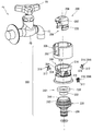
図8は、第2実施形態に係るホース接続具400が水栓f10に装着された状態を示す斜視図である。図9は、図8の断面図である。図10は、図8の分解斜視図である。図11は、図10の下側部材が更に分解された分解斜視図である。
FIG. 8 is a perspective view showing a state in which the
ホース接続具400は、上側部材500と、下側部材600とを有する。上側部材500と下側部材600とは、互いに取り外し可能に接続されている。
The
水栓f10は、水栓本体f20と、排出管f30と、操作部f40とを有する。更に水栓f10には、バルブ(図示されず)が内蔵されている。操作部f40を操作(回転)させることで、吐止水の切替及び吐水量の調整が可能である。 The faucet f10 includes a faucet body f20, a discharge pipe f30, and an operation unit f40. Further, a valve (not shown) is incorporated in the faucet f10. By operating (rotating) the operation unit f40, it is possible to switch the discharged water and adjust the discharged water amount.
本実施形態において、水栓f10は、水栓本体f20に対して排出管f30が回転可能である。当業者において、この水栓f10は、万能水栓と称されている。この水栓f10では、排出管f30が斜めに延びている。このため、取付状態において、上側部材500は下側部材600に対して斜め上側に位置する(図9参照)。
In this embodiment, the faucet f10 can rotate the discharge pipe f30 with respect to the faucet body f20. In the art, this faucet f10 is called a universal faucet. In the faucet f10, the discharge pipe f30 extends obliquely. Therefore, in the attached state, the
図11が示すように、上側部材500は、全体として一体的に成形された部材である。上側部材500は、全体として、U字型に曲がって延在する略帯状の部材である。上側部材500の詳細については、後述される。
As shown in FIG. 11, the
下側部材600は、排出管挿入部602と、下側係合部604と、ホース接続部606とを有する。排出管挿入部602は、円筒内面を有している。この排出管挿入部602に、排出管f30の下端部が挿入される。ホース接続部606には、ホース(ホースの端に取り付けられたコネクタ)が接続される。
The
図11が示すように、排出管挿入部602は、スライドリング608と、本体部610と、パッキン612とを有する。本体部610は、周方向の複数箇所(4箇所)に、開口614を有する。
As shown in FIG. 11, the discharge
下側係合部604は、係合弾性体616を有する。係合弾性体616は、周方向における複数箇所(4箇所)に設けられている。係合弾性体616は、基部617と、この基部617の上端から斜め下方に延びる係合爪618を有する。開口614のそれぞれに、係合弾性体616が配置されている。押圧されていない自然状態では、係合爪618は、開口614から、半径方向内側に突出している。
The
パッキン612は、フランジ部620と円筒部622とを有する。フランジ部620は、円筒部622の上端から、半径方向外側に延びている。
The packing 612 has a
図11が示すように、ホース接続部606は、ニップル部材630によって構成されている。ニップル部材630は、ホース接続部606と、ねじ部632とを有する。このねじ部632は、雄ねじである。一方、図9が示すように、本体部610はねじ部640を有する。このねじ部640は雌ねじである。ねじ部632とねじ部640とがねじ結合されている。
As shown in FIG. 11, the
ねじ部632とねじ部640とのねじ結合を利用して、パッキン612が固定されている。具体的には、パッキン612のフランジ部620が、本体部610の内側延在部642とニップル部材630の上端面644とによって挟まれている。上記ねじ結合のねじ込み量を増やすほど、内側延在部342と上端面644とが接近し、フランジ部620を強く挟み込む。この構成により、パッキン612は容易に且つ確実に固定されている。
The packing 612 is fixed using the screw connection between the
図12(a)は、右斜め上方から見た上側部材500の斜視図である。図12(b)は、右斜め下方から見た上側部材500の斜視図である。図12(c)は、左斜め下方から見た上側部材500の斜視図である。図13(a)は、上側部材500の平面図である。図13(b)は、上側部材500の正面図である。図13(c)は、上側部材500の底面図である。図14(a)は、上側部材500の右側面図である。図14(b)は、図13(b)のA−A線に沿った断面図である。図14(c)は、上側部材500の背面図である。
FIG. 12A is a perspective view of the
上側部材500は、右側壁部502と、左側壁部503と、連結部504とを有する。図13(c)が示すように、右側壁部502は、円周に沿った壁面を構成している。左側壁部503も、円周に沿った壁面を構成している。右側壁部502及び左側壁部503は、一つの円周面に沿った内壁面を構成している。
The
連結部504は帯状である。連結部504は、湾曲している。左右連結部504は、U字型に曲がっている。連結部504は、右側壁部502と左側壁部503とを繋いでいる。連結部504の一端に右側壁部502が設けられている。連結部504の他端に左側壁部503が設けられている。
The connecting
図12(a)及び図12(b)が示すように、上側部材500は下方に開放されている。更に、図12(a)〜(c)及び図13(b)が示すように、上側部材500は、正面側及び背面側に開放されている。右側壁部502及び左側壁部503は、周方向における2箇所が欠落した側壁部を構成している。換言すれば、上側部材500は、周方向における2箇所で分断された側壁部として、右側壁部502及び左側壁部503を有する。
As shown in FIGS. 12A and 12B, the
上側部材500は、排出管f3に上側から当接しうる当接部510を有する(図9参照)。連結部504の一部(頂部)が、当接部510である。
The
湾曲した(U字型の)連結部504により、前後方向に連通する空間が形成されている。すなわち、連結部504は、正面開口k1と、背面開口k2と、内部空間s1とを有する。内部空間s1は、正面開口k1と背面開口k2との間の空間である。
A curved (U-shaped) connecting
上側部材500は、上側係合部520を有している。上側係合部520は、右側壁部502及び左側壁部503のそれぞれに設けられている。すなわち、上側係合部520は、右側壁部502に設けられた第1係合部520Rと、左側壁部503に設けられた第2係合部520Lとを有する。上側係合部520は、凹みである。より詳細には、上側係合部520は、周方向に沿って設けられた溝である。右側壁部502の上側係合部520と左側壁部503の上側係合部520とを合わせると、一つの円周面に略沿った周溝が構成されている。ただし、右側壁部502と左側壁部503とが互いに分離していることに起因して、この周溝は、周方向の2箇所で分断されている(図13(b)及び図13(c)参照)。つまり、この周溝は、第1係合部520Rと第2係合部520Lとに分断されている。この上側係合部520は、係合弾性体616の係合爪618と係合しうる。
The
図12(a)及び図12(b)が示すように、右側壁部502と左側壁部503とにより、円周内面が構成されている。図13(c)が示すように、右側壁部502と左側壁部503との間に、内部空間s2が形成されている。この内部空間s2は、円柱状の空間である。
As shown in FIGS. 12A and 12B, the
取付状態では、右側壁部502と左側壁部503との間に、排出管f30が挿通される。排出管f30は管状であり、その断面は円形である。このため、排出管f30は、右側壁部502及び左側壁部503によって安定的に保持される。
In the attached state, the discharge pipe f30 is inserted between the
連結部504は弾性変形しうる。連結部504の弾性変形に起因して、内部空間s2の幅は変化しうる。換言すれば、連結部504の弾性変形に起因して、右側壁部502と左側壁部503との間の距離は変化しうる。排出管f30の太さに応じて、右側壁部502と左側壁部503との間の距離が調整されうる。このため、排出管f30の太さ(直径)及び曲がり具合が変動しても、上側部材500は排出管f30を安定的に保持しうる。上側部材500は、排出管f30の寸法及び形状に合わせて変形することができ、排出管への適応性に優れる。
The connecting
[接続状態及び取付状態]
図9が示すように、この上側部材500と下側部材600とが係合した接続状態により、曲がって延びる排出管f30が挟み込まれている。この挟み込みにより、ホース接続具400は排出管f30に固定されている。接続状態が維持されている限り、ホース接続具400が排出管f30から抜けることはない。
[Connection state and mounting state]
As shown in FIG. 9, the exhaust pipe f <b> 30 that is bent and bent is sandwiched by the connection state in which the
接続状態は、上側部材500及び下側部材600のうちの一方を他方に対して押し付けることにより、形成される。上側部材500を下側部材600に押し付けてもよいし、下側部材600を上側部材500に押し付けても良い。接続状態は、ワンタッチで形成される。接続状態の形成は非常に容易である。
The connection state is formed by pressing one of the
ホース接続具400の取付方法として、次の手順Cが可能である。この手順Cにより、接続状態の完了と同時に、取付状態が完了する。
(手順C)排出管f30の下端部を背面開口k2から内部空間s2へと通すことにより、上側部材500を排出管f30に装着する。次に、下側部材600を下から上側部材500に押し付ける。
As a method for attaching the
(Procedure C) The
なお、連結部504の弾性変形の度合いを高めることにより、前述した手順A及び手順Bも可能となる。一方、上記手順Cでは、連結部504の弾性変形を抑制することができるので、連結部504への負担が小さい。
Note that the procedure A and the procedure B described above can be performed by increasing the degree of elastic deformation of the connecting
手順AからCのいずれにおいても、上側係合部520(凹み)が下側係合部604(係合弾性体616)に係合することで、接続状態が完了する。上側部材500及び下側部材600のいずれか一方が他方に対して押し付けられる過程で、上側部材500の下端部が係合爪618を押圧する。係合爪618は斜め下方に向かって延びているため、上から下に向かって移動する上側部材500により容易に押圧され、半径方向外側に退行する。上側部材500の上側係合部520(凹み)が係合爪618の位置にまで達すると、係合爪618は、上側部材200による押圧から開放され、半径方向内側に突出する。この結果、係合爪618と上側係合部520とが係合する。換言すれば、上側係合部520が下側係合部604に係合する。このように、上側部材500及び下側部材600のうちの一方を他方に対して押し付けるだけで、接続状態を形成することができる。
In any of procedures A to C, the upper engagement portion 520 (dent) is engaged with the lower engagement portion 604 (engagement elastic body 616), thereby completing the connection state. In the process in which one of the
スライドリング608は、上側係合部520(凹み)と下側係合部604(係合爪618)との係合を保持するロック機能を有する。このロック機構の構成は、前述した第1実施形態と同様である。
The
ホース接続具400でも、接続状態の形成は容易であり、利便性が高い。また、上側部材500の変形容易性に起因して、排出管f30への適応性が高い。上述の通り、排出管f30の太さ及び曲がりによって、右側壁部502と左側壁部503との間の間隔が変化しうる。この変化によって、第1係合部520Rと第2係合部520Lとの間の距離も変化するが、この距離の変化は、上側係合部520と下側係合部604との間の係合に影響しない。このように、ホース接続具400は、排出管f30の形状の変化に対する適応性に優れ、且つ、取付状態が容易に形成されうる。周方向の複数箇所に配置されたねじを締め付ける従来のホース接続具と比べると、取付の容易性は明らかである。
Even in the
この第2実施形態においても、取付状態では、接続状態とされた上側部材500及び下側部材600が、排出管f3を挟み込んでいる。
Also in the second embodiment, in the attached state, the
図9が示すように、取付状態において、排出管f30の下端部が、パッキン612の円筒部622に内側から食い込んでいる。パッキン612は、排出管f30の外周面に密着している。この密着により、水密性が達成されている。
As shown in FIG. 9, the lower end portion of the discharge pipe f <b> 30 bites into the
取付状態では、接続状態が維持される限り、パッキン612は排出管f30に密着している。この密着により、水密性が保たれている。 In the attached state, as long as the connected state is maintained, the packing 612 is in close contact with the discharge pipe f30. The water tightness is maintained by this adhesion.
取付状態において、当接部510の当接位置c1は、排出管f3の下端部の中心線CL1よりも給水側(図9における右側)に位置する。したがって、排出管f30に対するホース接続具400の固定の確実性が向上している。
In the mounted state, the contact position c1 of the
取付状態において、ホース接続具400と排出管f30の間に遊びがあってもよい。すなわち、排出管f30が抜けない限り、取付状態のホース接続具400が、排出管f30に対して動いても良い。この遊びがある場合、当該遊びの全範囲において、パッキン612と排出管f30との間の接触圧(水密性)が維持されているのが好ましい。
In the mounted state, there may be play between the
第1実施形態のホース接続具100において、上側部材200の上側係合部220は、周方向における一部が欠落した欠落部206を有している。上側係合部220と下側係合部304との係合は、凹凸係合である。このため、欠落部206が存在していても、上側係合部220と下側係合部304との係合は、確実且つ安定的である。また、欠落部206は、排出管f3の形状に合わせて設けることができる。この欠落部206を有する上側部材200は、排出管への適応性に優れる。加えて、この欠落部206は、前述した手順A及び手順Bを可能とする。
In the
なお、上側部材200の内面形状と、排出管の外面の形状との間で、厳密な一致性は要求されない。この点は、図2に示された空間s4の大きさからも明らかである。取付状態では、接続状態にあるホース接続具から排出管が抜けない状態であればよい。曲がっている排出管の抜けを拘束するのに、上側部材200の内面と排出管の外面が一致している必要はない。このように、上側部材200は、排出管f3の形状との厳密な一致性を要することなく、排出管f3に対するホース接続具100の固定を可能としている。上側部材200は、上から被せることができるのに加えて、排出管への適合性に優れる。
In addition, exact agreement is not requested | required between the inner surface shape of the
第2実施形態のホース接続具400において、右側壁部502と左側壁部503との間には隙間506が存在する(図13(b)及び図13(c)参照)。これら隙間506は、上記欠落部である。すなわち、上側部材500の上側係合部520は、周方向における一部が欠落した欠落部506を有している。これらの欠落部506により、連結部504の変形が容易となる。欠落部506を有する上側部材500は、排出管f30への適応性に優れる。
In the
第2実施形態のホース接続具400においては、欠落部506が周方向における2箇所に設けられることで、上側係合部520が第1係合部520Rと第2係合部520Lとに分断されている。そして、上側部材500は、第1係合部520Rと第2係合部520Lとを繋ぐ連結部504を有している。この左右連結部504が、当接部510を有している。排出管f30は管状であるため、湾曲した連結部504は、排出管f30を挿通させつつ、上側から排出管f30に当接しやすい。この湾曲した連結部504は、排出管f30を安定的に挟み込むのに寄与している。
In the
第1実施形態において、パッキン312が、排出管f3の外面に密着しうる円筒部322を有している。この円筒部322の内径は、排出管f3の外径よりも小さい。排出管f3を円筒部322に挿入すると、円筒部322は排出管f3の外面に密着する。この密着により水密性が発現される。また、図2が示すように、円筒部322の外側に空間s3が設けられている。通水時に、この空間s3には水が流れ込む。よって、通水時には、水圧が円筒部322を排出管f3に向かって押圧する。このため、水密性がより一層高められている。
In the first embodiment, the packing 312 has a
ホース接続具の取付に関して、前述した手順A及び手順Bでは、上側部材は、上側から排出管に取り付けられている。したがって、排出管の上側から上側部材を、且つ、下側から下側部材を、それぞれ取り付けることができ、取付が容易である。前述した手順Cの場合、上側部材を上側から取り付けることはできないので、取付の容易性は、手順A及び手順Bに比べて低下する。しかしこの手順Cでも、手順A及び手順Bと同様に、ワンタッチ係合が可能である。これら手順A,B及びCでは、周方向の複数箇所に配置されたねじを締め付ける従来のホース接続具に比べで、取付の手間及び時間が大幅に短縮される。 Regarding the attachment of the hose connector, in the above-described procedure A and procedure B, the upper member is attached to the discharge pipe from the upper side. Therefore, the upper member can be attached from the upper side of the discharge pipe, and the lower member can be attached from the lower side, and attachment is easy. In the case of the procedure C described above, since the upper member cannot be attached from the upper side, the ease of attachment is reduced as compared with the procedure A and the procedure B. However, also in this procedure C, one-touch engagement is possible as in the procedures A and B. In these procedures A, B, and C, the labor and time for mounting are greatly reduced as compared with the conventional hose connector for fastening screws arranged at a plurality of locations in the circumferential direction.
前述した特表2007−528458号公報に記載の蛇口接続用カップリングとの比較において、本願実施形態の効果は、以下の通りである。 In comparison with the faucet connection coupling described in the aforementioned Japanese translation of PCT publication No. 2007-528458, the effect of the embodiment of the present application is as follows.
[効果1]
本願実施形態では、接続のための係合がねじ結合ではない。このため、ホースが接続される部材(下側部材)の回転規制が可能である。前述したホース接続具400は、上側部材500に対する下側部材600の回転を規制する凹凸係合を有する。図12(a)〜(c)が示すように、上側部材500は、係合凸部530を有している。係合凸部530は、挿入方向に延在している。一方、図10が示すように、下側部材600は、係合凸部530に係合する係合凹部650を有する。係合凹部650は、挿入方向に延在している。接続状態では、係合凸部530と係合凹部650とが係合する。この係合により、上側部材500に対する下側部材600の回転が規制される。なお、挿入方向とは、下側部材600に対して上側部材500が挿入されるときの挿入方向を意味する。
[Effect 1]
In the present embodiment, the engagement for connection is not a screw connection. For this reason, rotation regulation of the member (lower member) to which the hose is connected is possible. The
一方、特表2007−528458号公報に記載の蛇口接続用カップリングでは、接続のための係合がねじ結合であるため、上述の回転規制が不可能である。よって、ホースが接続される部材(下側部材)の回転を防止したい場合があっても、当該回転を防止することができない。回転を防止したい場合の一例は、分岐シャワーを付ける場合である。本願実施形態は、回転規制が可能であるため、利便性に優れる。 On the other hand, in the coupling for faucet connection described in JP-T-2007-528458, the above-mentioned rotation restriction is impossible because the engagement for connection is screw coupling. Therefore, even if it is desired to prevent rotation of the member (lower member) to which the hose is connected, the rotation cannot be prevented. An example of when it is desired to prevent rotation is when a branch shower is provided. The embodiment of the present application is excellent in convenience because the rotation can be restricted.
[効果2]
特表2007−528458号公報に記載の蛇口接続用カップリングでは、ホースの回転によって上記ねじ結合に緩みが生じうる。このねじ結合の緩みは、水漏れに繋がる。一方、本願実施形態では、接続のための係合がねじ結合ではないので、下側部材が回転しても水漏れは生じない。
[Effect 2]
In the faucet connection coupling described in JP-T-2007-528458, the screw connection may be loosened by rotation of the hose. This looseness of the screw connection leads to water leakage. On the other hand, in the embodiment of the present application, since the engagement for connection is not screw coupling, water leakage does not occur even when the lower member rotates.
[効果3]
蛇口の排出管内部の出口付近には、整流板が配置されていることが多い。特表2007−528458号公報に記載の蛇口接続用カップリングでは、蛇口の排出管内部に挿入される部材(接続具20)があるため、整流板が配置されている蛇口には取り付けることができない。一方、本願実施形態では、蛇口の排出管内部に挿入される部材はないため、整流板があっても取り付けられる。
[Effect 3]
A rectifying plate is often arranged near the outlet inside the faucet discharge pipe. In the coupling for faucet connection described in JP-T-2007-528458, since there is a member (connector 20) inserted into the faucet discharge pipe, it cannot be attached to the faucet in which the rectifying plate is arranged. . On the other hand, in this embodiment, since there is no member inserted inside the faucet discharge pipe, it is attached even if there is a current plate.
[効果4]
特表2007−528458号公報に記載の蛇口接続用カップリングでは、ねじ結合をどこまで締めればよいかが、分かりにくい。締め付けが不足している場合、水漏れが生じうる。また、締め付けが過剰である場合、パッキンが傷む。一方、本願実施形態では、係合の完了が分かりやすい。例えば、ホース接続具100においては、係合の完了と同時に、係合爪318が上側係合部220(凹み)の内側に突出する。この突出の際に音及び/又は振動が生じうる。これらの音及び/又は振動により、取り付けの完了を認識することができる。すなわち、本願実施形態では、聴覚又は触覚によって、取り付けの完了を認識することができる。
[Effect 4]
In the faucet connection coupling described in JP-T-2007-528458, it is difficult to know how much the screw connection should be tightened. If tightening is insufficient, water leakage can occur. In addition, if the tightening is excessive, the packing is damaged. On the other hand, in the embodiment of the present application, it is easy to understand completion of engagement. For example, in the
また、本願実施形態では、視覚によって取り付けの完了を認識することもできる。図8が示すように、上側部材500の連結部504は、外側突出部540を有する。外側突出部540は、左右のそれぞれに設けられている。第1の外側突出部540は、右側壁部502の上側に隣接して設けられている。第2の外側突出部540は、左側壁部503の上側に隣接して設けられている。下側部材600の上端面と外側突出部540との間隔によって、取り付けの完了を認識することができる。例えば、下側部材600の上端面と外側突出部540との間の隙間が無い状態を、取り付けの完了とすることができる。
Moreover, in this embodiment, completion of attachment can also be recognized visually. As shown in FIG. 8, the connecting
[効果5]
特表2007−528458号公報に記載の蛇口接続用カップリングでは、円筒状の固定具10に蛇口の排出管を通す必要があるため、排出管が長い場合には取り付けが困難となる。例えば、前述した万能水栓10(図10参照)への取り付けは、困難である。一方、前述した上側部材200及び上側部材500は、排出管への適応性に優れており、使用可能な水栓の範囲が広い。
[Effect 5]
In the faucet connection coupling described in JP-T-2007-528458, it is necessary to pass the faucet discharge pipe through the cylindrical fixture 10, so that it is difficult to mount the discharge pipe when the discharge pipe is long. For example, attachment to the universal faucet 10 (see FIG. 10) described above is difficult. On the other hand, the
[効果6]
特表2007−528458号公報に記載の蛇口接続用カップリングでは、締結具30とのねじ結合を締め付けることによって接続具20を上方に押し上げ、この押し上げ力によって水密性を確保している。よって、上述したワンタッチ接続をこの従来の構成に適用すると、水密性の確保が困難である。なぜなら、ワンタッチ接続では、通常、遊びが生ずるからである。一方、前述したホース接続具100及びホース接続具400では、中心線CL1の方向に沿って、パッキンと排出管との密着範囲が確保されている。このため、当該遊びがあっても水密性が確保されている。すなわち、本願実施形態では、ワンタッチ接続を採用しても水密性が確保される。
[Effect 6]
In the faucet connection coupling described in JP-T-2007-528458, the connection tool 20 is pushed upward by tightening the screw connection with the fastener 30, and the watertightness is secured by this push-up force. Therefore, when the one-touch connection described above is applied to this conventional configuration, it is difficult to ensure water tightness. This is because play is usually generated in the one-touch connection. On the other hand, in the
[効果7]
前述したホース接続具100のパッキン312は、中心線CL1に沿って延びる円筒部322を有している。この円筒部322の長さによって、パッキン312と排出管f3との密着面積が確保され、水密性が高められている。このパッキン312が従来の蛇口接続用カップリングに適用された場合、この円筒部322の長さに加えて、固定具10と締結具30との間のねじ結合の長さが必要となる。ところが、図3に示されるような水栓f1の場合、排出管f3が短い。このような場合にパッキン312を適用すると、固定具10と締結具30との間のねじ結合の長さを確保できない。一方、本願実施形態では、上述の係合構造が採用されているので、係合部分の長さ(中心線CL1方向の長さ)を短くすることができる。本願実施形態のホース接続具100は、排出管への適応性に優れる。
[Effect 7]
The packing 312 of the
[効果8]
特表2007−528458号公報に記載の蛇口接続用カップリングでは、固定具10と締結具30とでねじを締める作業が必要である。これに対して、上述したワンタッチ接続では、取り付けの作業性に優れる。
[Effect 8]
In the faucet connection coupling described in JP-T-2007-528458, an operation of fastening screws with the fixture 10 and the fastener 30 is necessary. In contrast, the above-described one-touch connection is excellent in mounting workability.
[効果9]
下側部材300は、既存のニップル継手と同じ構造であるため、他の製品との共通化が可能である。この共通化により、下側部材300は、既存のホース継手や、既存の散水ノズル等に接続することが可能となる。
[Effect 9]
Since the
[効果10]
本願実施形態のホース接続具では、取り付け及び取り外しが容易であるため、清掃しやすい。
[Effect 10]
In the hose connector according to the embodiment of the present application, it is easy to clean because it is easy to attach and remove.
[効果11]
本願実施形態のホース接続具では、パッキンの円筒部が、排出管の外径に合わせて拡張することができる。よって、多様な外径の排出管に対して適合しうる。なお、本願実施形態で用いられているようなパッキンは、ウイングパッキンとも称される。
[Effect 11]
In the hose connector according to the present embodiment, the cylindrical portion of the packing can be expanded according to the outer diameter of the discharge pipe. Therefore, it can adapt to the discharge pipe of various outer diameters. Note that the packing used in the embodiment of the present application is also referred to as a wing packing.
[効果12]
特表2007−528458号公報に記載の蛇口接続用カップリングでは、接続のための係合がねじ結合である。当該ねじ結合の部分に欠落部を設けるのが好ましくなく、雄ねじ及び雌ねじとも完全な円筒面に設けられるのが好ましい。この観点から、上側部材及び下側部材の形状が制約されている。一方、ホース接続具100では、上側部材200及び下側部材300に欠落部を設けても、係合が達成されている。またホース接続具400では、上側係合部520が第1係合部520Rと第2係合部520Lとに分断されており、これらの距離が変化しうるにも関わらず、係合が達成されている。本願実施形態は、上側部材及び下側部材の形状の自由度に優れる。
[Effect 12]
In the faucet connection coupling described in JP-T-2007-528458, the engagement for connection is screw coupling. It is not preferable to provide a missing portion in the screw connection portion, and it is preferable that both the male screw and the female screw are provided on a complete cylindrical surface. From this viewpoint, the shapes of the upper member and the lower member are restricted. On the other hand, in the
[効果13]
特表2007−528458号公報に記載の蛇口接続用カップリングでは、固定具10と締結具30とのねじ結合の軸力により、接続具20を押し上げて、水密性を確保している。よってこの従来技術では、上側部材(締結具30)が、パッキン(接続具20)に圧縮力を付与している。この圧縮力を付与するため、固定具10及び締結具30を円筒状とし、両者の間にねじ結合が締結されている。この構成では、固定具10及び締結具30の形状の自由度が低く、排出管への適合性が限定される。一方、ホース接続具100では、接続状態において、上側部材200が、パッキン312に圧縮力を付与していない。上側部材200は、下側部材300の移動を規制しているが、パッキン312の圧縮力を高めるような力を付与していない。仮に、下側部材300がなんらかの外力によって下方に引っ張られた場合には、結果として上側部材200は下側部材300に上方への力を付与することになる。この上方への力はパッキン312の圧縮力に影響しうるが、通常の使用状態では、上側部材200は下側部材300に上方への力を付与しない。
[Effect 13]
In the faucet connection coupling described in JP-T-2007-528458, the connection tool 20 is pushed up by the axial force of the screw connection between the fixing tool 10 and the fastening tool 30 to ensure watertightness. Therefore, in this prior art, the upper member (fastener 30) applies a compressive force to the packing (connector 20). In order to apply this compressive force, the fixture 10 and the fastener 30 are cylindrical, and a screw connection is fastened between them. In this structure, the freedom degree of the shape of the fixing tool 10 and the fastener 30 is low, and the adaptability to a discharge pipe is limited. On the other hand, in the
このように、上側部材200の役割は下側部材300の移動を規制するのみである。上側部材200は、下側部材300に対して上方向への力を付与する必要がない。よって、上側部材200の形状自由度を高くすることができ、多様な排出管f3に適合することが可能となる。
Thus, the role of the
本実施形態のホース接続具には以上のような効果を奏するが、実際の使用に際して特に顕著な効果は、取り付けの作業性及び排出管への適合性である。 The hose connector of the present embodiment has the effects as described above, and particularly remarkable effects in actual use are mounting workability and adaptability to the discharge pipe.
取り付けの作業性に関して、ホース接続具100では、上側部材200を上から被せるだけで取り付けることができる。前述した手順A及び手順Bのいずれにしても、上側部材200は排出管f3の上から被せ、下側部材300は下から排出管f3を挿入して、両者をワンタッチ接続するだけである。片手での取り付けが可能である点については、前述のとおりである。ホース接続具400についても同様であり、ワンタッチ接続が可能である。この取り付けの作業量は、従来のホース接続具に比べて、はるかに少ない。排出管への適合性に関して、前述の通り、上側部材200及び上側部材500は、多様な排出管に適合しうる。また上述の通り、ウイングパッキンは多様な排出管に適合しうる。このように、実施形態に係るホース接続具は、取り付けの作業性に優れ、且つ、適合する水栓の範囲が従来品よりも広いという効果を有する。実施形態に係るホース接続具は、利便性が極めて高い。
Regarding the workability of attachment, the
ホース接続具100では、係合弾性体316が本体部310とは別部材である。しかし、係合弾性体316を本体部310と一体化してもよいことは、言うまでもない。また係合弾性体316の数は限定されない。接続状態の安定性の観点から、係合弾性体316の数は、2以上であるのが好ましい。ホース接続具100の製造コストを考慮すると、係合弾性体316の数は、6以下が好ましく、5以下がより好ましく、4以下がより好ましい。係合弾性体316が複数である場合、これらは周方向に均等に配分されるのが好ましい。
In the
接続状態のロック機構に関して、上述の通り、スライドリングの移動を規制するスライド規制部材が設けられてもよい。上述の通り、スライド規制部材は、スライドリングをロック位置に維持するのに寄与する。仮に使用者が意図しない下向き外力がスライドリングに作用しても、スライド規制部材により接続状態が確実に維持されうる。スライド規制部材が隙間g1(図2参照)に配置される部材(例えば前述のリング部材)である場合、ロック位置の維持がより一層確実となる一方で、当該部材の装着には若干の手間を要する。これに対して、スライド規制部材が上述の付勢部材(スプリング等)である場合、当該手間が削減されるメリットがある一方で、ロック位置の維持の確実性は若干低下する。 Regarding the lock mechanism in the connected state, as described above, a slide restricting member that restricts the movement of the slide ring may be provided. As described above, the slide restricting member contributes to maintaining the slide ring in the locked position. Even if a downward external force not intended by the user acts on the slide ring, the connection state can be reliably maintained by the slide restricting member. When the slide restricting member is a member (for example, the above-described ring member) disposed in the gap g1 (see FIG. 2), the lock position can be more reliably maintained, but the mounting of the member requires a little trouble. Cost. On the other hand, when the slide restricting member is the above-described biasing member (spring or the like), there is a merit that the labor is reduced, but the certainty of maintaining the lock position is slightly lowered.
前述の通り、本体部310とニップル部材330との間の固定構造として、ねじ止めが採用されている(図2及び図4参照)。この固定構造は、ねじ止めに限定されない。この固定構造として、ねじ止め、接着及び溶着が例示される。上述の通り、パッキン312の固定を容易とする観点からは、ねじ止めが好ましい。一方、成形金型の複雑性を抑制する観点からは、接着及び溶着が好ましい。更に、量産時の加工安定性を考慮すると、溶着が好ましい。
As described above, screwing is employed as a fixing structure between the
水栓へのホース接続具の固定に関して、上述の通り、当接部210の当接位置c1は中心線CL1よりも給水側に位置するのが好ましい(図2参照)。一方、通常の取付状態では、本体部310は水栓f1に接しておらず、パッキン312が水栓f1に接している。すなわち、パッキン312が下側部材300全体を支持している。ただし、ホース接続具100が傾いた場合には、本体部310が排出管f3に当接する。この当接により、更なるホース接続具100の傾きが防止され、ひいてはホース接続具100の外れが防止されている。また、本体部310の代わりに、スライドリング308又はニップル部材330が水栓f1に当接する場合もある。このように、ホース接続具100の姿勢によっては、下側部材300のいずれかの部分が水栓f1に当接して、ホース接続具100の傾きを防止し、ひいてはホース接続具100の外れが防止されている。なお、ホース接続具100が傾いた場合等において、当接部210は水栓f1に当接しない状態となりうる。
Regarding the fixing of the hose connector to the faucet, as described above, the contact position c1 of the
このように、ホース接続具100の姿勢によって、当接部210又は下側部材300の少なくともいずれかが水栓f1に当接し、ホース接続具100の更なる傾斜を抑制する。この当接により、ホース接続具100の傾斜が所定の臨界点までに規制され、ホース接続具100からの排出管f3の抜けが防止される。当接部210、スライドリング308、本体部310及びニップル部材330からなる群から選択される1又は2以上の部材は、傾斜抑制部材として機能する。
As described above, depending on the posture of the
例えば図8に示されるホース接続具400において、上側部材500の形状は略帯状であって、排出管f30の形状との一致性は低い。このような上側部材500であっても、排出管f30に対して確実に固定することができる。排出管f30の形状との一致性が低いということは、上側部材500が適合しうる排出管f30の範囲が広いことを意味している。すなわち、上側部材500は、多様な排出管f30に適合しうる。排出管f3の表面は滑らかな曲面であり、滑りやすいため、ホース接続具の固定は容易でないと思われていた。しかし、上側部材500と下側部材600とによって曲がって延びる排出管f30を挟み込むことで、上側部材500の形状がそれほど制約されずに、排出管f30への固定が可能であることが判明した。本発明のホース接続具では、取付作業が容易な上に、排出管への適応性が高く、且つ、確実な固定が可能である。
For example, in the
図2において両矢印D1で示されているのは、空間s3の軸方向長さである。パッキン312に対する排出管f3の挿入長さの自由度を高めると共に、水圧に起因する水密性を高める観点から、長さD1は、5mm以上が好ましく、7mm以上がより好ましく、8mm以上がより好ましい。ホース接続具100の小型化の観点から、長さD1は、16mm以下が好ましく、14mm以下がより好ましく、12mm以下が更に好ましい。図2の実施形態では、長さD1は9mmとされた。なお、軸方向とは、中心線CL1の方向を意味する。
In FIG. 2, what is indicated by a double-headed arrow D1 is the axial length of the space s3. The length D1 is preferably 5 mm or more, more preferably 7 mm or more, and more preferably 8 mm or more from the viewpoint of increasing the degree of freedom of the insertion length of the discharge pipe f3 with respect to the packing 312 and increasing the water tightness due to water pressure. In light of downsizing of the
図2において両矢印D2で示されているのは、円筒部322の軸方向長さである。パッキン312に対する排出管f3の挿入長さの自由度を高める観点から、長さD2は、9mm以上が好ましく、10mm以上がより好ましく、12mm以上がより好ましい。ホース接続具100の小型化の観点から、長さD2は、20mm以下が好ましく、18mm以下がより好ましく、16mm以下が更に好ましい。図2の実施形態では、長さD2は14mmとされた。
In FIG. 2, a double arrow D <b> 2 indicates the axial length of the
図2において両矢印D3で示されているのは、空間s3の半径方向長さの最大値である。排出管f3の外径の自由度を高める観点から、長さD3は、1mm以上が好ましく、2mm以上がより好ましく、3mm以上がより好ましい。ホース接続具100の小型化の観点から、長さD3は、8mm以下が好ましく、7mm以下がより好ましく、6mm以下が更に好ましい。図2の実施形態では、長さD3は4mmとされた。長さD3は、排出管f3が挿入されていない状態で測定される。なお、半径方向とは、中心線CL1に交わり且つ中心線CL1に対して垂直な直線の方向を意味する。
In FIG. 2, what is indicated by a double-headed arrow D3 is the maximum value of the length in the radial direction of the space s3. From the viewpoint of increasing the degree of freedom of the outer diameter of the discharge pipe f3, the length D3 is preferably 1 mm or more, more preferably 2 mm or more, and more preferably 3 mm or more. From the viewpoint of miniaturization of the
図13(c)において両矢印D4で示されるのは、右側壁部502と左側壁部503との間の離間距離である。細い排出管f3を保持することを考慮すると、距離D4を確保するのが好ましい。この観点から、距離D4は、0.5mm以上が好ましく、1mm以上がより好ましく、1.5mm以上がより好ましい。太い排出管f3を通した場合、連結部504が変形し、当該離間距離が拡大しうる。第1係合部520Rと第2係合部520Lとの連続性を考慮すると、当該離間距離が過大となるのは好ましくない。この観点から、距離D4は、6mm以下が好ましく、5mm以下がより好ましく、4mm以下がより好ましい。図13の実施形態では、距離D4は2mmとされた。なお、距離D4は、上側部材500に外力が付与されていない自然状態で測定される。
In FIG. 13C, a double arrow D4 indicates a separation distance between the
図6において両矢印θ1で示されているのは、欠落部206の中心角である。多様な太さの排出管f3への適合性を高める観点から、角θ1は、60°以上が好ましく、70°以上がより好ましく、80°以上が更に好ましい。上側係合部220の周方向範囲を増やす観点から、角θ1は、120°以下が好ましく、110°以下がより好ましく、100°以下がより好ましい。図6の実施形態では、角θ1は90°とされた。なお、角θ1の中心は、上側部材200の内面又は外面の少なくとも一部に存在する円周面の中心とされうる。
In FIG. 6, what is indicated by a double arrow θ <b> 1 is the central angle of the missing
図13において両矢印θ2で示されているのは、正面開口k1(及び背面開口k2)の中心角である。多様な太さの排出管f3への適合性を高める観点から、角θ2は、60°以上が好ましく、70°以上がより好ましく、80°以上が更に好ましい。繰り返しの弾性変形における連結部504の耐久性を考慮すると、角θ2は、120°以下が好ましく、110°以下がより好ましく、100°以下がより好ましい。図13の実施形態では、角θ2は90°とされた。なお、角θ2は、上側部材500に外力が付与されていない自然状態で測定される。
In FIG. 13, what is indicated by a double-headed arrow θ2 is the central angle of the front opening k1 (and the rear opening k2). From the viewpoint of enhancing the adaptability to the discharge pipe f3 having various thicknesses, the angle θ2 is preferably 60 ° or more, more preferably 70 ° or more, and further preferably 80 ° or more. Considering the durability of the connecting
図15は、第3実施形態に係るホース接続具700が水栓f1に装着された状態を示す斜視図である。図16は、図15の断面図である。
FIG. 15 is a perspective view showing a state in which the
ホース接続具700は、上側部材800と、下側部材300とを有する。上側部材800と下側部材300とは、互いに取り外し可能に接続されている。
The
前述したホース接続具100とこのホース接続具700との相違は、第2上側係合部222の有無のみである。図16が示すように、上側部材800は、前述した上側部材200と同様に、上側係合部220を有している。加えて、上側部材800は、第2上側係合部222を有している。接続状態において、上側係合部220と第2上側係合部222とでは、軸方向位置が相違する。上側係合部220に加えて、第2上側係合部222にも、下側係合部304(係合弾性体316の係合爪318)が係合しうる。
The difference between the
これら複数の上側係合部220,222は、長さが異なる排出管f3への適応性を高める。排出管f3が図16のように短いとき、係合爪318は上側係合部220に係合する。排出管f3が長いときは、係合爪318が第2上側係合部222に係合することができる。このように、複数の上側係合部を設けることで、長さが異なる排出管f3への適合性が高まる。この観点から、接続状態において軸方向位置が相違する複数の上側係合部が設けられるのが好ましい。この実施形態では上側係合部は2段であるが、3段以上の多段であってもよい。
The plurality of upper engaging
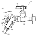
図17は、第4実施形態に係るホース接続具900が水栓f10に装着された状態を示す斜視図である。図18は、図17の断面図である。図19は、図17の分解斜視図である。図20は、図19の下側部材が更に分解された分解斜視図である。
FIG. 17 is a perspective view showing a state in which the
ホース接続具900は、上側部材1000と、下側部材1100とを有する。上側部材1000と下側部材1100とは、互いに取り外し可能に接続されている。
The
水栓f10は、水栓本体f20と、排出管f30と、操作部f40とを有する。更に水栓f10には、バルブ(図示されず)が内蔵されている。操作部f40を操作(回転)させることで、吐止水の切替及び吐水量の調整が可能である。 The faucet f10 includes a faucet body f20, a discharge pipe f30, and an operation unit f40. Further, a valve (not shown) is incorporated in the faucet f10. By operating (rotating) the operation unit f40, it is possible to switch the discharged water and adjust the discharged water amount.
本実施形態において、水栓f10は、水栓本体f20に対して排出管f30が回転可能である。当業者において、この水栓f10は、万能水栓と称されている。この水栓f10では、排出管f30が斜めに延びている。このため、取付状態において、上側部材1000は下側部材1100に対して斜め上側に位置する(図17参照)。
In this embodiment, the faucet f10 can rotate the discharge pipe f30 with respect to the faucet body f20. In the art, this faucet f10 is called a universal faucet. In the faucet f10, the discharge pipe f30 extends obliquely. For this reason, in the attached state, the
上側部材1000は、全体として一体的に成形された部材である。上側部材1000は、全体として、周方向の一部が開放され、且つ下方に開放された部材である。上側部材1000の詳細については、後述される。
The
下側部材1100は、排出管挿入部1102と、リング係合体1104と、ホース接続部1106とを有する。排出管挿入部1102は、円筒内面を有している。この排出管挿入部1102に、排出管f30の下端部が挿入される。ホース接続部1106には、ホース(ホースの端に取り付けられたコネクタ)が接続される。ホース接続部1106は、Oリング1108を有する。Oリング1108は、接続部における水密性を高める。
The
図20が示すように、排出管挿入部1102は、本体部1110と、パッキン1112とを有する。本体部1110は、全体として円筒状の部材である。本体部1110は、周方向の複数箇所(3箇所)に、貫通孔1114を有する(図20参照)。パッキン1112は、ウイングパッキンである。
As shown in FIG. 20, the discharge
本体部1110は、欠落部1110aを有する。欠落部1110aは、本体部1110の上端面から下方に向かって延在している。この欠落部1110aは、排出管f30と下側部材1100との干渉を防止している。欠落部1110aにより、ホース接続具900が取り付け可能な水栓f10の形状自由度が高まる。
The
リング係合体1104は、上側部材1000の上側係合部1020と係合しうる下側係合部の一例である。リング係合体1104は、有端の環状部材である。リング係合体1104の詳細については、後述される。
The
リング係合体1104は、本体部1110(下側部材1100)に、取り外し可能に取り付けられている。リング係合体1104は、本体部1110(下側部材1100)の外面に取り付けられている(図19)。リング係合体1104は、本体部1110(下側部材1100)の側面に取り付けられている。本体部1110(下側部材1100)は、リング係合体1104が嵌まり込む周溝1116を有する(図20参照)。
The
上側部材1000と下側部材1100とが互いに係合した接続状態において、リング係合体1104は、下側部材1100(本体部1110)から取り外されうる。本願では、前記接続状態における上側部材1000と下側部材1100との相対的な位置関係が、正規接続位置とも称される。上側部材1000及び下側部材1100が正規接続位置にあるとき、リング係合体1104は下側部材1100から取り外されうる。上側部材1000及び下側部材1100(リング係合体1104を除く)が正規接続位置にあるとき、リング係合体1104は下側部材1100に取り付けられうる。
In the connected state in which the
図18及び図20が示すように、パッキン1112は、フランジ部1120と円筒部1122とを有する。フランジ部1120は、円筒部1122の上端から、半径方向外側に延びている。
As shown in FIGS. 18 and 20, the packing 1112 includes a
取付状態において、排出管f30は、フランジ部1120の円筒部1122を通過している。自然状態における円筒部1122の内径は、この円筒部1122を通過している排出管f30の外径よりも小さい。よてt、取付状態において、フランジ部1120の円筒部1122は、排出管f30の外面に密着している(図18参照)。この密着により、水漏れが防止されている。
In the attached state, the discharge pipe f30 passes through the
図20が示すように、ホース接続部1106は、ニップル部材1130によって構成されている。ニップル部材1130は、ホース接続部1106と、結合部1132とを有する。この結合部1132が、本体部1110の内側に挿入されつつ固定されている。パッキン1112は、本体部1110とニップル部材1130とに挟まれて、固定されている。
As shown in FIG. 20, the
図21(a)は、右斜め上方から見た上側部材1000の斜視図である。図21(b)は、右斜め下方から見た上側部材1000の斜視図である。図21(c)は、左斜め下方から見た上側部材1000の斜視図である。図22(a)は、上側部材1000の正面図である。図22(b)は、図22(a)のA−A線に沿った断面図である。図22(c)は、上側部材1000の背面図である。
FIG. 21A is a perspective view of the
上側部材1000は、側壁部1002と、上壁部1004とを有する。上側部材1000は下方に開放されている。側壁部1002は、略円筒形状であるが、その周方向における一部が欠落している。すなわち、側壁部1002は欠落部1006を有する。
The
上側部材1000は、排出管f3に上側から当接しうる当接部1010を有する(図18参照)。上側部材1000の上壁部1004において、欠落部1006の上側に位置する部分が、当接部1010である。
The
取付状態において、排出管f30は、上側部材1000の欠落部1006を通り、上側部材1000の内部空間を経由して、下側部材1100に至る。
In the attached state, the discharge pipe f30 passes through the missing
上側部材1000は、当接面M1を有する。当接面M1は、上側部材1000の下端に設けられている。当接面M1は、傾斜面である。上側部材1000及び下側部材1100のうちの一方を他方に対して押し付ける過程で、当接面M1は、リング係合体1104の係合突出部1104a(後述)に当接しうる。
The
上側部材1000は、上側係合部1020を有している。上側係合部1020は、側壁部1002に設けられている。上側係合部1020は、凹みである。より詳細には、上側係合部1020は、周方向に沿って設けられた溝である。ただし、欠落部1006が存在する領域では、上側係合部1020(溝)は途切れている。この上側係合部1020は、リング係合体1104の係合突出部1104a(後述)と係合しうる。
The
上側部材1000は、回り止め凹部1030を有する。この回り止め凹部1030は、挿入方向に延びる溝であり、この溝の下端は開放されている。一方、本体部1110は、回り止め突部1118を有する(図20参照)。接続状態において、回り止め凹部1030と回り止め突部1118とが係合する。凹凸係合により、下側部材1100(本体部1110)に対する上側部材1000の回転が規制されている。
The
図23(a)は、リング係合体1104の斜視図であり、図23(b)は他の視点から見たリング係合体1104の斜視図である。図23(c)はリング係合体1104の平面図であり、図23(d)はリング係合体1104の底面図である。
FIG. 23A is a perspective view of the
リング係合体1104は、略C型の部材である。リング係合体1104は、有端の環状部材である。リング係合体1104は、係合突出部1104aと、第1端t1と、第2端t2と、連結部1104bとを有する。
The
リング係合体1104の材質は、樹脂である。連結部1104bは、弾性変形しうる。リング係合体1104は、第1端t1と第2端t2との距離が大きくなるように弾性変形しうる。このリング係合体1104の弾性変形が、拡開変形とも称される。拡開変形したリング係合体1104は、弾性力により、自然状態に戻ろうとする。すなわち、拡開変形したリング係合体1104は、第1端t1と第2端t2との距離が小さくなるように弾性変形しうる。このリング係合体1104の弾性変形が、縮径変形とも称される。
The material of the
リング係合体1104は、半径方向内側に突出している複数の係合突出部1104aを有する。図23の実施形態では、複数(3つ)の係合突出部1104aとして、係合突出部p1、係合突出部p2及び係合突出部p3が設けられている。係合突出部p1と係合突出部p2との間に、係合突出部p3が設けられている。係合突出部p3と第1端t1との間に、係合突出部p1が設けられている。係合突出部p3と第2端t2との間に、係合突出部p2が設けられている。
The
連結部1104bは、係合突出部1104a同士をつないでいる。第1の連結部1104bは、係合突出部p1と係合突出部p3とをつないでいる。第2の連結部1104bは、係合突出部p2と係合突出部p3とをつないでいる。係合突出部1104aは、連結部1104bに対して半径方向内側に突出している。
The connecting
前述の通り、このリング係合体1104は、下側部材1100(本体部1110)の外面に取り付けられる。この取り付けは、容易である。リング係合体1104の第1端t1及び第2端t2を本体部1110(の周溝1116)に押し付けると、リング係合体1104は、拡開変形を経て縮径変形し、本体部1110(の周溝1116)に外嵌される。同時に、係合突出部1104aのそれぞれは、本体部1110の貫通孔1114を貫通し、本体部1110の内面よりも内側に突出する(図19参照)。このリング係合体1104の状態が正規装着状態とも称される。
As described above, the
[接続状態及び取付状態]
図18が示すように、この上側部材1000と下側部材1100とが係合した接続状態により、曲がって延びる排出管f30が挟み込まれている。この挟み込みにより、ホース接続具900は排出管f30に固定されている。接続状態が維持されている限り、ホース接続具900が排出管f30から抜けることはない。
[Connection state and mounting state]
As shown in FIG. 18, the exhaust pipe f <b> 30 that is bent and bent is sandwiched by the connection state in which the
接続状態は、上側部材1000及び下側部材1100のうちの一方を他方に対して押し付けることにより、形成される。上側部材1000を下側部材1100に押し付けてもよいし、下側部材1100を上側部材1000に押し付けても良い。接続状態は、ワンタッチで形成される。接続状態の形成は非常に容易である。
The connection state is formed by pressing one of the
図24(a)及び図24(b)は、上側部材1000と下側部材1100との接続について説明する断面図である。この接続では、リング係合体1104が正規装着状態にある。上側部材1000及び下側部材1100の一方を他方に押し付けることで、上側部材1000の当接面M1が係合突出部1104a(係合突出部p1からp3のぞれぞれ)に当接する。当接面M1は、上側部材1000の端面に近づくほど上側部材1000の内側となるように傾斜している。このため、上側部材1000が下側部材1100側に移動するほど、当接面M1は係合突出部1104aを外側に変位させる。この変位により、リング係合体1104は拡開変形する。上側部材1000の上側係合部1020が係合突出部1104aの位置に達すると、リング係合体1104の弾性復元力により、リング係合体1104が縮径変形する。この縮径変形により、係合突出部1104aが上側係合部1020に入り込む(係合する)(図24(b))。
FIGS. 24A and 24B are cross-sectional views illustrating the connection between the
ホース接続具900の取付方法として、次の手順D及びEが可能である。この手順D及びEにより、接続状態の完了と同時に、取付状態が完了する。
(手順D)排出管f3に上側部材1000を上から被せて、次に、排出管f30を排出管挿入部1102に挿入しつつ、下側部材1100を下から上側部材1000に押し付ける。
(手順E)排出管f30に下側部材1100を下から取付けて、次に上側部材1000を上から下側部材1100に押し付ける。
As a method for attaching the
(Procedure D) The
(Procedure E) The
取り付けの作業性に関して、ホース接続具900では、上側部材1000を上から被せるだけで取り付けることができる。前述した手順D及び手順Eのいずれにしても、上側部材1000は排出管f30の上から被せ、下側部材1100は下から排出管f30を挿入して、ワンタッチ接続を行うだけである。よって、片手での取り付けも可能である。
Regarding the workability of attachment, the
これらの手順D及びEでは、上側部材1000と下側部材1100とを接続する前に、リング係合体1104が下側部材1100に装着されている。換言すれば、上側部材1000と下側部材1100とを接続する前に、リング係合体1104が正規装着状態とされる。これが事前装着とも称される。事前装着の場合、上側部材1000及び下側部材1100のうちの一方を他方に対して押し付けるだけで、接続状態を形成することができる。すなわち、ワンタッチ接続が可能となる。
In these procedures D and E, the
なお、上述の通り、リング係合体1104は、下側部材1100の外側に取り外し可能に取り付けられている。よって、上側部材1000と下側部材1100とを接続状態と同じ位置関係とした後に、リング係合体1104を装着することもできる。これは、事後装着とも称される。円滑な接続(ワンタッチ接続)の観点からは、この事後装着よりも、上記事前装着が好ましい。すなわち、上記手順D及びEのように、リング係合体1104を予め正規装着状態とした上で取り付けるのが好ましい。換言すれば、上側部材1000及び下側部材1100のうちの一方を他方に対して押し付ける前に、下側部材1100にリング係合体1104が装着されている(リング係合体1104は正規装着状態にある)のが好ましい。
As described above, the
このように、ホース接続具900では、下側係合部が有端の環状部材であるリング係合体1104によって構成されている。上側部材1000は、上側係合部としての凹部1020と、当接面M1を有している。下側部材1100は、貫通孔1114を有している(図20)。リング係合体1104は、下側部材1100の外側に嵌められている。リング係合体1104の弾性変形(拡開変形及び縮径変形)に起因して、リング係合体1104は下側部材1100の外面に取り外し可能に取り付けられている。リング係合体1104が正規装着状態にあるとき、係合突出部1104aが貫通孔1114を通過して下側部材1100の内部に突出している(図19)。当接面M1は、上側部材1000及び下側部材1100のうちの一方を他方に対して押し付けることにより、下側部材1100の内部に突出する係合突出部1104aに当接してリング係合体1104を拡開変形させるように構成されている(図24(a))。係合突出部1104aは、前記拡開変形後のリング係合体の縮径変形により凹部1020に入り込んでいる。これにより前記接続状態が形成される(図18、図24(b))。
Thus, in the
安定した係合の観点から、係合突出部1104aの数は、2以上が好ましく、3以上がより好ましい。係合突出部1104aの大きさを確保すると、係合突出部1104aの数は限定される。また、係合突出部1104aの数が過大であると、構造が複雑化し、円滑な係合の点で好ましくない。この観点から、係合突出部1104aの数は、6以下が好ましく、4以下がより好ましい。
From the viewpoint of stable engagement, the number of
リング係合体1104は、上下を逆としても装着可能である。リング係合体1104が上下逆向きに装着されても、上側部材1000の当接面M1(傾斜面)は、リング係合体1104の係合突出部1104aを押圧しうる。リング係合体1104が上下逆向きに装着されても、ワンタッチ接続が可能である。
The
前述した第1〜第3実施形態に記載の接続構造(係合爪タイプ)と、この第4実施形態に係るホース接続具900の接続構造(リング係合体タイプ)とは、いずれも、水圧が作用しても水栓から抜けにくい。すなわち、いずれのタイプも、高い抜け防止性能を有する。特に、ホース接続具900は、より高い抜け防止性能を有する。高水圧時には、上側部材と下側部材とを引き離す方向の力(水圧力)が大きくなる。前述した係合爪タイプの場合、周方向に分散して配置された複数の係合爪の全てが確実に係合するように、上側係合部と係合爪との間で挿入方向のクリアランス(係合の遊び)を比較的大きくとる必要がある。また、係合爪は水圧力により変形しうる。これに対して、リング係合体タイプは、前記クリアランスが少なくて済み、且つ、高水圧時でもリング係合体1104の変形は少ない。よって、リング係合体タイプのホース接続具は、高水圧時における抜け防止性能が極めて高い。もちろん、係合爪タイプのホース接続具も、実用的な抜け防止性能を有しうる。
Both the connection structure (engagement claw type) described in the first to third embodiments and the connection structure (ring engagement body type) of the
リング係合体タイプは、係合爪タイプに比べて、構造が単純であり、部品点数が少ない。よって、リング係合体タイプは、組み立てが容易であり、故障も少ない。また、リング係合体は着脱可能であるため、単独での部品交換が容易である。更に、リング係合体は使用者でも着脱可能であるため、リング係合体を装着することなく出荷することもでき、使用者側での部品交換も可能となる。そして、リング係合タイプは、単純な構造でありながら、クリアランス(遊び)が少なく確実性の高い係合を実現しうる。 The ring engagement body type has a simple structure and a smaller number of parts than the engagement claw type. Therefore, the ring engagement body type is easy to assemble and has few failures. In addition, since the ring engagement body is detachable, it is easy to replace parts independently. Further, since the ring engagement body can be attached and detached even by the user, it can be shipped without mounting the ring engagement body, and parts can be replaced on the user side. The ring engagement type has a simple structure and can realize engagement with high reliability with little clearance (play).
上側部材の材質として、樹脂及び金属が例示される。樹脂としては、強度及び生産性に優れる樹脂が好ましい。成形容易性の観点から、樹脂としては、熱可塑性樹脂が好ましい。成形容易性の観点から、より好ましい樹脂として、ポリプロピレン(PP)、アクリロニトリルブタジエンスチレン共重合体(ABS)、ポリアセタール(POM)が例示される。強度の観点から、ポリアセタール(POM)がより好ましい。上述した実施形態において、上側部材の材質は、ポリアセタール(POM)とされた。 Examples of the material of the upper member include resin and metal. As the resin, a resin excellent in strength and productivity is preferable. From the viewpoint of ease of molding, the resin is preferably a thermoplastic resin. From the viewpoint of ease of molding, more preferable resins include polypropylene (PP), acrylonitrile butadiene styrene copolymer (ABS), and polyacetal (POM). From the viewpoint of strength, polyacetal (POM) is more preferable. In the embodiment described above, the material of the upper member is polyacetal (POM).
係合弾性体の材質として、樹脂及び金属が例示される。樹脂としては、強度及び生産性に優れる樹脂が好ましい。成形容易性の観点から、樹脂としては、熱可塑性樹脂が好ましい。成形容易性の観点から、より好ましい樹脂として、ポリプロピレン(PP)、アクリロニトリルブタジエンスチレン共重合体(ABS)、ポリアセタール(POM)が例示される。強度の観点から、ポリアセタール(POM)がより好ましい。上述した実施形態において、係合弾性体の材質は、ポリアセタール(POM)とされた。 Resin and metal are illustrated as a material of an engagement elastic body. As the resin, a resin excellent in strength and productivity is preferable. From the viewpoint of ease of molding, the resin is preferably a thermoplastic resin. From the viewpoint of ease of molding, more preferable resins include polypropylene (PP), acrylonitrile butadiene styrene copolymer (ABS), and polyacetal (POM). From the viewpoint of strength, polyacetal (POM) is more preferable. In the embodiment described above, the material of the engagement elastic body is polyacetal (POM).
スライドリングの材質として、樹脂及び金属が例示される。樹脂としては、安価で生産性に優れる樹脂が好ましい。成形容易性の観点から、樹脂としては、熱可塑性樹脂が好ましい。成形容易性の観点から、より好ましい樹脂として、ポリプロピレン(PP)、アクリロニトリルブタジエンスチレン共重合体(ABS)、ポリアセタール(POM)が例示される。安価で且つ強度に優れるとの観点から、ABSがより好ましい。上述した実施形態において、スライドリングの材質は、ABSとされた。 Examples of the material of the slide ring include resin and metal. As the resin, an inexpensive resin excellent in productivity is preferable. From the viewpoint of ease of molding, the resin is preferably a thermoplastic resin. From the viewpoint of ease of molding, more preferable resins include polypropylene (PP), acrylonitrile butadiene styrene copolymer (ABS), and polyacetal (POM). From the viewpoint of being inexpensive and excellent in strength, ABS is more preferable. In the embodiment described above, the material of the slide ring is ABS.
本体部の材質として、樹脂及び金属が例示される。樹脂としては、安価で生産性に優れる樹脂が好ましい。成形容易性の観点から、樹脂としては、熱可塑性樹脂が好ましい。成形容易性の観点から、より好ましい樹脂として、ポリプロピレン(PP)、アクリロニトリルブタジエンスチレン共重合体(ABS)、ポリアセタール(POM)が例示される。安価で且つ強度に優れるとの観点から、ABSがより好ましい。上述した実施形態において、本体部の材質は、ABSとされた。 Resin and metal are illustrated as a material of a main-body part. As the resin, an inexpensive resin excellent in productivity is preferable. From the viewpoint of ease of molding, the resin is preferably a thermoplastic resin. From the viewpoint of ease of molding, more preferable resins include polypropylene (PP), acrylonitrile butadiene styrene copolymer (ABS), and polyacetal (POM). From the viewpoint of being inexpensive and excellent in strength, ABS is more preferable. In the above-described embodiment, the material of the main body is ABS.
ホース接続部の材質として、樹脂及び金属が例示される。樹脂としては、安価で生産性に優れる樹脂が好ましい。成形容易性の観点から、樹脂としては、熱可塑性樹脂が好ましい。成形容易性の観点から、より好ましい樹脂として、ポリプロピレン(PP)、アクリロニトリルブタジエンスチレン共重合体(ABS)、ポリアセタール(POM)が例示される。安価で且つ強度に優れるとの観点から、ABSがより好ましい。上述した実施形態において、ホース接続部の材質は、ABSとされた。 Resin and metal are illustrated as a material of a hose connection part. As the resin, an inexpensive resin excellent in productivity is preferable. From the viewpoint of ease of molding, the resin is preferably a thermoplastic resin. From the viewpoint of ease of molding, more preferable resins include polypropylene (PP), acrylonitrile butadiene styrene copolymer (ABS), and polyacetal (POM). From the viewpoint of being inexpensive and excellent in strength, ABS is more preferable. In the above-described embodiment, the material of the hose connection portion is ABS.
リング係合体1104は、強度に優れているのが好ましく、且つ、撓んで戻るという特性が必要である。リング係合体1104の材質として、樹脂が好ましい。樹脂としては、成形容易性の観点から、熱可塑性樹脂が好ましい。成形容易性の観点から、ポリプロピレン(PP)、アクリロニトリルブタジエンスチレン共重合体(ABS)及びポリアセタール(POM)がより好ましい。強度に優れるとの観点から、POMがより好ましい。
The
本願には、独立形式請求項に係る発明に含まれない他の発明も記載されている。本願の請求項及び実施形態に記載されたそれぞれの形態、部材、構成等は、それぞれが有する作用効果に基づく発明として認識される。 The present application also describes other inventions not included in the invention according to the independent claims. Each form, member, configuration, and the like described in the claims and embodiments of the present application are recognized as inventions based on the respective functions and effects.
上記各実施形態で示されたそれぞれの形態、部材、構成等は、これら実施形態の全ての形態、部材又は構成をそなえなくても、個々に、本願請求項に係る発明をはじめとした、本願記載の全発明に適用されうる。 Each form, member, configuration, etc. shown in each of the above embodiments is not limited to all of the forms, members, or configurations of these embodiments. It can be applied to all described inventions.
以上説明されたホース接続具は、あらゆる水栓に適用されうる。 The hose connector described above can be applied to any faucet.
100・・・ホース接続具
200・・・上側部材
206・・・欠落部
210・・・当接部
220・・・上側係合部
300・・・下側部材
302・・・排出管挿入部
304・・・下側係合部
306・・・ホース接続部
308・・・スライドリング
310・・・本体部
312・・・パッキン
316・・・係合弾性体
318・・・係合爪
330・・・ニップル部材
400・・・ホース接続具
500・・・上側部材
502・・・右側壁部
503・・・左側壁部
504・・・連結部
520・・・上側係合部
600・・・下側部材
606・・・ホース接続部
608・・・スライドリング
610・・・下側部材の本体部
612・・・パッキン
900・・・ホース接続具
1000・・・上側部材
1020・・・上側係合部(凹部)
1100・・・下側部材
1104・・・リング係合体
1104a・・・係合突出部
DESCRIPTION OF
316: engagement
DESCRIPTION OF
Claims (6)
前記上側部材が、蛇口の排出管に上側から当接しうる当接部と、上側係合部とを有しており、
前記下側部材が、パッキンを有する排出管挿入部と、前記上側係合部と係合しうる下側係合部と、ホース接続部と、を有しており、
前記上側係合部と前記下側係合部とが互いに係合した接続状態により、曲がって延びる前記排出管を挟み込むことができ、
前記上側部材及び前記下側部材のうちの一方を他方に対して押し付けることにより、前記接続状態が形成され、
前記上側部材が、上側から前記排出管に取り付けることができるホース接続部。 Having an upper member and a lower member that can be detachably connected to each other;
The upper member has a contact portion that can contact the discharge pipe of the faucet from the upper side, and an upper engagement portion,
The lower member has a discharge pipe insertion portion having packing, a lower engagement portion that can be engaged with the upper engagement portion, and a hose connection portion,
Due to the connection state in which the upper engagement portion and the lower engagement portion are engaged with each other, the discharge pipe extending in a bent manner can be sandwiched,
By pressing one of the upper member and the lower member against the other, the connection state is formed ,
The hose connection part which the said upper member can attach to the said discharge pipe from the upper side .
前記上側部材が、蛇口の排出管に上側から当接しうる当接部と、上側係合部とを有しており、 The upper member has a contact portion that can contact the discharge pipe of the faucet from the upper side, and an upper engagement portion,
前記下側部材が、パッキンを有する排出管挿入部と、前記上側係合部と係合しうる下側係合部と、ホース接続部と、を有しており、 The lower member has a discharge pipe insertion portion having packing, a lower engagement portion that can be engaged with the upper engagement portion, and a hose connection portion,
前記上側係合部と前記下側係合部とが互いに係合した接続状態により、曲がって延びる前記排出管を挟み込むことができ、 Due to the connection state in which the upper engagement portion and the lower engagement portion are engaged with each other, the discharge pipe extending in a bent manner can be sandwiched,
前記上側部材及び前記下側部材のうちの一方を他方に対して押し付けることにより、前記接続状態が形成され、 By pressing one of the upper member and the lower member against the other, the connection state is formed,
前記下側係合部が、有端の環状部材であるリング係合体によって構成されており、 The lower engagement portion is constituted by a ring engagement body that is an end-shaped annular member,
前記リング係合体が、係合突出部を有しており、 The ring engagement body has an engagement protrusion;
前記上側部材が、前記上側係合部としての凹部と、当接面を有しており、 The upper member has a concave portion as the upper engaging portion and a contact surface,
前記下側部材が、貫通孔を有しており、 The lower member has a through hole;
前記リング係合体が正規装着状態にあるとき、前記係合突出部が前記貫通孔を通過して前記下側部材の内部に突出しており、 When the ring engagement body is in a normal mounting state, the engagement protrusion protrudes into the lower member through the through hole,
前記当接面が、前記上側部材及び前記下側部材のうちの一方を他方に対して押し付けることにより、前記下側部材の内部に突出する前記係合突出部に当接して前記リング係合体を拡開変形させるように構成されており、 The abutting surface presses one of the upper member and the lower member against the other, thereby abutting against the engagement protrusion protruding inside the lower member to cause the ring engaging body to move. Configured to expand and deform,
前記係合突出部が、前記拡開変形後の前記リング係合体の縮径変形により前記凹部に入り込んでいるホース接続具。 The hose connector, wherein the engagement protrusion enters the recess due to the diameter-reducing deformation of the ring engagement body after the expansion deformation.
前記上側部材が、蛇口の排出管に上側から当接しうる当接部と、上側係合部とを有しており、
前記下側部材が、パッキンを有する排出管挿入部と、前記上側係合部と係合しうる下側係合部と、ホース接続部と、を有しており、
前記上側係合部と前記下側係合部とが互いに係合した接続状態により、曲がって延びる前記排出管を挟み込むことができ、
前記接続状態において、前記上側部材が、前記パッキンに圧縮力を付与しておらず、
前記下側係合部が、有端の環状部材であるリング係合体によって構成されており、
前記リング係合体が、係合突出部を有しており、
前記上側部材が、前記上側係合部としての凹部と、当接面を有しており、
前記下側部材が、貫通孔を有しており、
前記リング係合体が正規装着状態にあるとき、前記係合突出部が前記貫通孔を通過して前記下側部材の内部に突出しており、
前記当接面が、前記上側部材及び前記下側部材のうちの一方を他方に対して押し付けることにより、前記下側部材の内部に突出する前記係合突出部に当接して前記リング係合体を拡開変形させるように構成されており、
前記係合突出部が、前記拡開変形後の前記リング係合体の縮径変形により前記凹部に入り込んでいるホース接続具。 Having an upper member and a lower member that can be detachably connected to each other;
The upper member has a contact portion that can contact the discharge pipe of the faucet from the upper side, and an upper engagement portion,
The lower member has a discharge pipe insertion portion having packing, a lower engagement portion that can be engaged with the upper engagement portion, and a hose connection portion,
Due to the connection state in which the upper engagement portion and the lower engagement portion are engaged with each other, the discharge pipe extending in a bent manner can be sandwiched,
In the connected state, the upper member does not apply compressive force to the packing ,
The lower engagement portion is constituted by a ring engagement body that is an end-shaped annular member,
The ring engagement body has an engagement protrusion;
The upper member has a concave portion as the upper engaging portion and a contact surface,
The lower member has a through hole;
When the ring engagement body is in a normal mounting state, the engagement protrusion protrudes into the lower member through the through hole,
The abutting surface presses one of the upper member and the lower member against the other, thereby abutting against the engagement protrusion protruding inside the lower member to cause the ring engaging body to move. Configured to expand and deform,
The hose connector , wherein the engagement protrusion enters the recess due to the diameter-reducing deformation of the ring engagement body after the expansion deformation .
前記上側部材が、前記第1係合部と前記第2係合部とを繋ぐ連結部を有しており、
前記連結部が、前記当接部を有している請求項4に記載のホース接続部。 The upper engagement portion is divided into a first engagement portion and a second engagement portion by providing the missing portion at two locations in the circumferential direction,
The upper member has a connecting portion connecting the first engaging portion and the second engaging portion;
The hose connection part according to claim 4 , wherein the connecting part has the contact part.
前記円筒部の外側に空間が設けられている請求項1から5のいずれか1項に記載のホース接続部。 The packing has a cylindrical portion that can be in close contact with the outer surface of the discharge pipe,
The hose connection part according to any one of claims 1 to 5 , wherein a space is provided outside the cylindrical part.
Applications Claiming Priority (2)
| Application Number | Priority Date | Filing Date | Title |
|---|---|---|---|
| JP2016112542 | 2016-06-06 | ||
| JP2016112542 | 2016-06-06 |
Related Child Applications (1)
| Application Number | Title | Priority Date | Filing Date |
|---|---|---|---|
| JP2016243484A Division JP6836776B2 (en) | 2016-06-06 | 2016-12-15 | Hose connector |
Publications (2)
| Publication Number | Publication Date |
|---|---|
| JP6110550B1 true JP6110550B1 (en) | 2017-04-05 |
| JP2017219190A JP2017219190A (en) | 2017-12-14 |
Family
ID=58666385
Family Applications (3)
| Application Number | Title | Priority Date | Filing Date |
|---|---|---|---|
| JP2016160283A Active JP6110550B1 (en) | 2016-06-06 | 2016-08-18 | Hose fittings |
| JP2016243484A Active JP6836776B2 (en) | 2016-06-06 | 2016-12-15 | Hose connector |
| JP2017047654A Active JP6714293B2 (en) | 2016-06-06 | 2017-03-13 | Hose fitting |
Family Applications After (2)
| Application Number | Title | Priority Date | Filing Date |
|---|---|---|---|
| JP2016243484A Active JP6836776B2 (en) | 2016-06-06 | 2016-12-15 | Hose connector |
| JP2017047654A Active JP6714293B2 (en) | 2016-06-06 | 2017-03-13 | Hose fitting |
Country Status (1)
| Country | Link |
|---|---|
| JP (3) | JP6110550B1 (en) |
Families Citing this family (3)
| Publication number | Priority date | Publication date | Assignee | Title |
|---|---|---|---|---|
| JP6110550B1 (en) * | 2016-06-06 | 2017-04-05 | 株式会社タカギ | Hose fittings |
| JP6775810B1 (en) * | 2020-03-10 | 2020-10-28 | 株式会社タカギ | Hose connector |
| KR102357125B1 (en) * | 2021-04-26 | 2022-02-08 | 신영현 | Coupler for curbed tubular |
Citations (6)
| Publication number | Priority date | Publication date | Assignee | Title |
|---|---|---|---|---|
| GB2269537A (en) * | 1992-08-10 | 1994-02-16 | Tony Kao | Non-powered, portable apparatus for cleaning the mouth |
| JPH0914531A (en) * | 1995-06-29 | 1997-01-17 | Naniwa Seisakusho:Kk | Connecting fixture for faucet directly connected water purifier |
| JP2006307872A (en) * | 2005-04-26 | 2006-11-09 | Jiyopuratsukusu Kk | Faucet joint |
| JP2007528458A (en) * | 2003-11-27 | 2007-10-11 | ナム,ジュン−ウク | Coupling for tap connection |
| KR20100011308U (en) * | 2009-05-12 | 2010-11-22 | 주식회사 아폴로산업 | -a hose-coupling device for bib cook |
| JP2011226631A (en) * | 2010-04-21 | 2011-11-10 | Sin Dong Yeo | Connecting device of water supply hose for faucet |
Family Cites Families (1)
| Publication number | Priority date | Publication date | Assignee | Title |
|---|---|---|---|---|
| JP6110550B1 (en) * | 2016-06-06 | 2017-04-05 | 株式会社タカギ | Hose fittings |
-
2016
- 2016-08-18 JP JP2016160283A patent/JP6110550B1/en active Active
- 2016-12-15 JP JP2016243484A patent/JP6836776B2/en active Active
-
2017
- 2017-03-13 JP JP2017047654A patent/JP6714293B2/en active Active
Patent Citations (6)
| Publication number | Priority date | Publication date | Assignee | Title |
|---|---|---|---|---|
| GB2269537A (en) * | 1992-08-10 | 1994-02-16 | Tony Kao | Non-powered, portable apparatus for cleaning the mouth |
| JPH0914531A (en) * | 1995-06-29 | 1997-01-17 | Naniwa Seisakusho:Kk | Connecting fixture for faucet directly connected water purifier |
| JP2007528458A (en) * | 2003-11-27 | 2007-10-11 | ナム,ジュン−ウク | Coupling for tap connection |
| JP2006307872A (en) * | 2005-04-26 | 2006-11-09 | Jiyopuratsukusu Kk | Faucet joint |
| KR20100011308U (en) * | 2009-05-12 | 2010-11-22 | 주식회사 아폴로산업 | -a hose-coupling device for bib cook |
| JP2011226631A (en) * | 2010-04-21 | 2011-11-10 | Sin Dong Yeo | Connecting device of water supply hose for faucet |
Also Published As
| Publication number | Publication date |
|---|---|
| JP2017219194A (en) | 2017-12-14 |
| JP6836776B2 (en) | 2021-03-03 |
| JP2017219190A (en) | 2017-12-14 |
| JP2017219193A (en) | 2017-12-14 |
| JP6714293B2 (en) | 2020-06-24 |
Similar Documents
| Publication | Publication Date | Title |
|---|---|---|
| JP6110550B1 (en) | Hose fittings | |
| TWI681139B (en) | Coupling for joining pipe elements | |
| JPWO2008044296A1 (en) | Fitting device | |
| KR102304858B1 (en) | High pressure hose connector for water pipe with anti-twist function | |
| WO2021075298A1 (en) | Pipe joint | |
| JP2008095765A (en) | Hose joint | |
| JP4719176B2 (en) | Pipe fitting | |
| JP6525636B2 (en) | How to connect backup ring, fittings and pipes | |
| JP4871142B2 (en) | Detachment prevention structure of pipe joint part, locking part large diameter remodeling method of insertion pipe part and locking part large diameter remodeling tool for insertion pipe part | |
| JP4542364B2 (en) | Pipe connection structure and installation method of in-pipe work machine to insertion tube | |
| KR101778100B1 (en) | Flexible joint for sprinkler and manufacturing method thereof | |
| JP2005090531A (en) | Pipe joint | |
| KR101857027B1 (en) | Spring band sealed type one touch pipe coupler | |
| TW201537078A (en) | Pipe joint | |
| JP2007321872A (en) | Pipe fitting and pipe connection structure | |
| JP2018115739A (en) | Pipe joint | |
| JP2017214992A (en) | Hose joint | |
| JP4352434B1 (en) | One-touch fitting for piping | |
| KR200473400Y1 (en) | Apparatus for connecting a pipe and a connecting pipe | |
| JPS5916633Y2 (en) | Connections for pipes, etc. | |
| JP3187036U (en) | Clamp ring | |
| JP4220211B2 (en) | Piping connector | |
| KR100493329B1 (en) | Pipe coupler | |
| JP7098215B2 (en) | How to assemble joints and guide members | |
| JP6775810B1 (en) | Hose connector |
Legal Events
| Date | Code | Title | Description |
|---|---|---|---|
| TRDD | Decision of grant or rejection written | ||
| A01 | Written decision to grant a patent or to grant a registration (utility model) |
Free format text: JAPANESE INTERMEDIATE CODE: A01 Effective date: 20170207 |
|
| A61 | First payment of annual fees (during grant procedure) |
Free format text: JAPANESE INTERMEDIATE CODE: A61 Effective date: 20170309 |
|
| R150 | Certificate of patent or registration of utility model |
Ref document number: 6110550 Country of ref document: JP Free format text: JAPANESE INTERMEDIATE CODE: R150 |
|
| R250 | Receipt of annual fees |
Free format text: JAPANESE INTERMEDIATE CODE: R250 |
|
| R250 | Receipt of annual fees |
Free format text: JAPANESE INTERMEDIATE CODE: R250 |
|
| R250 | Receipt of annual fees |
Free format text: JAPANESE INTERMEDIATE CODE: R250 |
|
| R250 | Receipt of annual fees |
Free format text: JAPANESE INTERMEDIATE CODE: R250 |
|
| R250 | Receipt of annual fees |
Free format text: JAPANESE INTERMEDIATE CODE: R250 |