JP6101038B2 - Recording apparatus and recording data creation method - Google Patents
Recording apparatus and recording data creation method Download PDFInfo
- Publication number
- JP6101038B2 JP6101038B2 JP2012229240A JP2012229240A JP6101038B2 JP 6101038 B2 JP6101038 B2 JP 6101038B2 JP 2012229240 A JP2012229240 A JP 2012229240A JP 2012229240 A JP2012229240 A JP 2012229240A JP 6101038 B2 JP6101038 B2 JP 6101038B2
- Authority
- JP
- Japan
- Prior art keywords
- image
- recording
- data
- sheet
- preliminary ejection
- Prior art date
- Legal status (The legal status is an assumption and is not a legal conclusion. Google has not performed a legal analysis and makes no representation as to the accuracy of the status listed.)
- Active
Links
- 238000000034 method Methods 0.000 title claims description 83
- 230000008569 process Effects 0.000 claims description 56
- 238000004519 manufacturing process Methods 0.000 claims 1
- 238000002360 preparation method Methods 0.000 claims 1
- 238000012545 processing Methods 0.000 description 41
- 238000003860 storage Methods 0.000 description 21
- 238000010586 diagram Methods 0.000 description 13
- 230000032258 transport Effects 0.000 description 9
- 239000003086 colorant Substances 0.000 description 8
- 239000000758 substrate Substances 0.000 description 8
- 238000001035 drying Methods 0.000 description 6
- 238000004804 winding Methods 0.000 description 6
- 230000006870 function Effects 0.000 description 4
- 239000007788 liquid Substances 0.000 description 4
- 238000001454 recorded image Methods 0.000 description 4
- 239000003795 chemical substances by application Substances 0.000 description 3
- 238000005520 cutting process Methods 0.000 description 3
- 239000004065 semiconductor Substances 0.000 description 3
- 238000006243 chemical reaction Methods 0.000 description 2
- 238000012790 confirmation Methods 0.000 description 2
- 238000010438 heat treatment Methods 0.000 description 2
- 238000012423 maintenance Methods 0.000 description 2
- 238000012546 transfer Methods 0.000 description 2
- MHABMANUFPZXEB-UHFFFAOYSA-N O-demethyl-aloesaponarin I Natural products O=C1C2=CC=CC(O)=C2C(=O)C2=C1C=C(O)C(C(O)=O)=C2C MHABMANUFPZXEB-UHFFFAOYSA-N 0.000 description 1
- XUIMIQQOPSSXEZ-UHFFFAOYSA-N Silicon Chemical compound [Si] XUIMIQQOPSSXEZ-UHFFFAOYSA-N 0.000 description 1
- 230000015572 biosynthetic process Effects 0.000 description 1
- 230000004397 blinking Effects 0.000 description 1
- 239000000919 ceramic Substances 0.000 description 1
- 230000008859 change Effects 0.000 description 1
- 238000004140 cleaning Methods 0.000 description 1
- 238000007599 discharging Methods 0.000 description 1
- 230000000694 effects Effects 0.000 description 1
- 239000004744 fabric Substances 0.000 description 1
- 239000011521 glass Substances 0.000 description 1
- 238000010191 image analysis Methods 0.000 description 1
- 238000003702 image correction Methods 0.000 description 1
- 230000006872 improvement Effects 0.000 description 1
- 239000010985 leather Substances 0.000 description 1
- 239000002184 metal Substances 0.000 description 1
- 238000005192 partition Methods 0.000 description 1
- 239000002985 plastic film Substances 0.000 description 1
- 229920006255 plastic film Polymers 0.000 description 1
- 238000012805 post-processing Methods 0.000 description 1
- 238000007781 pre-processing Methods 0.000 description 1
- 229910052710 silicon Inorganic materials 0.000 description 1
- 239000010703 silicon Substances 0.000 description 1
- 239000007787 solid Substances 0.000 description 1
- 238000007711 solidification Methods 0.000 description 1
- 230000008023 solidification Effects 0.000 description 1
- 238000005092 sublimation method Methods 0.000 description 1
- -1 thermal transfer Substances 0.000 description 1
- 239000002023 wood Substances 0.000 description 1
Images


Classifications
-
- B—PERFORMING OPERATIONS; TRANSPORTING
- B41—PRINTING; LINING MACHINES; TYPEWRITERS; STAMPS
- B41J—TYPEWRITERS; SELECTIVE PRINTING MECHANISMS, i.e. MECHANISMS PRINTING OTHERWISE THAN FROM A FORME; CORRECTION OF TYPOGRAPHICAL ERRORS
- B41J2/00—Typewriters or selective printing mechanisms characterised by the printing or marking process for which they are designed
- B41J2/005—Typewriters or selective printing mechanisms characterised by the printing or marking process for which they are designed characterised by bringing liquid or particles selectively into contact with a printing material
- B41J2/01—Ink jet
- B41J2/015—Ink jet characterised by the jet generation process
- B41J2/04—Ink jet characterised by the jet generation process generating single droplets or particles on demand
- B41J2/045—Ink jet characterised by the jet generation process generating single droplets or particles on demand by pressure, e.g. electromechanical transducers
- B41J2/04501—Control methods or devices therefor, e.g. driver circuits, control circuits
- B41J2/04541—Specific driving circuit
-
- B—PERFORMING OPERATIONS; TRANSPORTING
- B41—PRINTING; LINING MACHINES; TYPEWRITERS; STAMPS
- B41J—TYPEWRITERS; SELECTIVE PRINTING MECHANISMS, i.e. MECHANISMS PRINTING OTHERWISE THAN FROM A FORME; CORRECTION OF TYPOGRAPHICAL ERRORS
- B41J2/00—Typewriters or selective printing mechanisms characterised by the printing or marking process for which they are designed
- B41J2/005—Typewriters or selective printing mechanisms characterised by the printing or marking process for which they are designed characterised by bringing liquid or particles selectively into contact with a printing material
- B41J2/01—Ink jet
- B41J2/135—Nozzles
- B41J2/165—Prevention or detection of nozzle clogging, e.g. cleaning, capping or moistening for nozzles
- B41J2/16517—Cleaning of print head nozzles
- B41J2/1652—Cleaning of print head nozzles by driving a fluid through the nozzles to the outside thereof, e.g. by applying pressure to the inside or vacuum at the outside of the print head
- B41J2/16526—Cleaning of print head nozzles by driving a fluid through the nozzles to the outside thereof, e.g. by applying pressure to the inside or vacuum at the outside of the print head by applying pressure only
- B41J2/16529—Idle discharge on printing matter
-
- B—PERFORMING OPERATIONS; TRANSPORTING
- B41—PRINTING; LINING MACHINES; TYPEWRITERS; STAMPS
- B41J—TYPEWRITERS; SELECTIVE PRINTING MECHANISMS, i.e. MECHANISMS PRINTING OTHERWISE THAN FROM A FORME; CORRECTION OF TYPOGRAPHICAL ERRORS
- B41J2/00—Typewriters or selective printing mechanisms characterised by the printing or marking process for which they are designed
- B41J2/005—Typewriters or selective printing mechanisms characterised by the printing or marking process for which they are designed characterised by bringing liquid or particles selectively into contact with a printing material
- B41J2/01—Ink jet
- B41J2/135—Nozzles
- B41J2/165—Prevention or detection of nozzle clogging, e.g. cleaning, capping or moistening for nozzles
- B41J2/16585—Prevention or detection of nozzle clogging, e.g. cleaning, capping or moistening for nozzles for paper-width or non-reciprocating print heads
Landscapes
- Ink Jet (AREA)
- Accessory Devices And Overall Control Thereof (AREA)
- Particle Formation And Scattering Control In Inkjet Printers (AREA)
Description
本発明は記録装置及び記録制御方法に関し、特に、例えば、インクジェットフルライン記録ヘッドを備えた記録装置及びその装置の記録制御方法に関する。 The present invention relates to a recording apparatus and a recording control method, and more particularly, to a recording apparatus including an inkjet full-line recording head and a recording control method for the apparatus.
従来、インクジェット記録装置では、記録のためにインク液滴を吐出する小さいノズルの集合体である記録ヘッドを用いて記録を行っている。しかし、この記録ヘッドのノズル孔は非常に小さいため、均一なインク吐出を行い、画像品位を満たすためにはそのノズルが乾かないように一定時間毎に予備吐出するなどの対応が必要となる。 Conventionally, in an ink jet recording apparatus, recording is performed using a recording head that is an assembly of small nozzles that eject ink droplets for recording. However, since the nozzle hole of this recording head is very small, in order to perform uniform ink discharge and satisfy the image quality, it is necessary to take preparatory discharges at regular intervals so that the nozzles do not dry.
更に、ロール紙のような連続した記録媒体(シート)に対して、そのシート幅と同じ幅のフルライン記録ヘッド(以下、記録ヘッド)を用いて記録をする場合には、次のような制御を行っていた。即ち、画像品位保持用のパターンを定期的もしくは何かの条件によって、記録する画像間に挿入することで、記録の品位を保つような制御を行っていた。(特許文献1、2)
Further, when recording is performed on a continuous recording medium (sheet) such as roll paper using a full line recording head (hereinafter referred to as a recording head) having the same width as the sheet width, the following control is performed. Had gone. That is, the control for maintaining the quality of the recording is performed by inserting the pattern for maintaining the image quality between the images to be recorded periodically or under some condition. (
さて、実際の画像記録では、画像のサイズが同じサイズの画像をシートに連続記録するだけでなく、印刷ジョブの切り替えや印刷ジョブ内の画像データの並びによってはサイズが異なる画像が混在した順で画像を記録することもある。例えば、シートの幅より小さい画像も混在して記録する場合もあり、この場合には、その画像前後の画像記録の条件によっては、その画像記録に用いたフルライン記録ヘッドの部位は、画像品位保持用のパターンを記録するために必要としない場合もある。 In actual image recording, not only images with the same image size are continuously recorded on the sheet, but also in the order in which images of different sizes are mixed depending on the switching of print jobs and the arrangement of image data in the print job. An image may be recorded. For example, an image smaller than the sheet width may be recorded together. In this case, depending on the image recording conditions before and after the image, the part of the full-line recording head used for the image recording may be image quality. It may not be necessary to record a holding pattern.
しかしながら上記従来例では、その際にも、画像記録に使用していない部位を含めて記録ヘッドの画像品位保持を行うために、記録ヘッドの記録幅全体にパターンを記録していた。このため、画像品位保持用のパターンが記録画像の間に定期的に記録されるので、連続シートの中に、ユーザにとって記録結果としては不必要な画像品位保持用のパターンが入ってしまう。その結果、連続シートにおける画像の記録可能枚数が減ってしまう。また画像品位保持用のパターンの記録を行うので、実質的な記録のスループットが低下するという問題があった。 However, in the above-described conventional example, the pattern is recorded over the entire recording width of the recording head in order to maintain the image quality of the recording head including the portion not used for image recording. For this reason, since the image quality holding pattern is periodically recorded between the recorded images, the image quality holding pattern unnecessary for the user as a recording result enters the continuous sheet. As a result, the recordable number of images on the continuous sheet is reduced. Further, since a pattern for maintaining image quality is recorded, there has been a problem that a substantial recording throughput is lowered.
本発明は上記従来例に鑑みてなされたもので、予備吐出のためのパターンを記録する場合にも、連続画像記録可能枚数を減らすことなく、記録スループットが低下することなく良好な記録が可能な記録装置及び記録制御方法を提供することを目的とする。 The present invention has been made in view of the above-described conventional example. Even when a pattern for preliminary ejection is recorded, it is possible to perform good recording without reducing the recording throughput without reducing the number of continuous images that can be recorded. An object is to provide a recording apparatus and a recording control method.
上記目的を達成するために本発明の記録装置は、次のような構成からなる。 In order to achieve the above object, the recording apparatus of the present invention has the following configuration.
即ち、本発明の記録装置は、シートを第1方向に搬送する搬送ユニットと、前記第1方向と交差する第2方向に沿ってノズルが複数形成され、記録データに基づいて当該複数のノズルからシートにインクを吐出するライン型記録ヘッドと、ホスト装置から第1画像と当該第1画像に続く第2画像とを含む画像データが入力される入力手段と、を備える記録装置であって、前記複数のノズルのそれぞれについて、前記第1画像の記録の完了前に最後にインクを吐出したシート上の位置から前記第2画像の記録の際に最初にインクを吐出するシート上の位置までの長さを算出する算出手段と、前記算出手段による算出結果に基づいて、前記第1画像と前記第2画像の間に前記ライン型記録ヘッドによる予備吐出が必要であるか否かを判断する判断手段と、前記判断手段により前記予備吐出が必要であると判断された場合、前記予備吐出のためのデータを前記画像データの前記第1画像と前記第2画像の間に追加して前記記録データを作成する作成手段と、を備え、前記作成手段は、前記判断手段により前記予備吐出が必要でないと判断された場合、前記予備吐出のためのデータを前記第1画像と前記第2画像の間に追加せずに前記第1画像と前記第2画像の間を詰めて前記記録データを作成することを特徴とする。
That is, the recording apparatus of the present invention includes a transport unit that transports a sheet in a first direction, and a plurality of nozzles formed along a second direction that intersects the first direction. A recording apparatus comprising: a line-type recording head that discharges ink to a sheet; and input means for inputting image data including a first image and a second image following the first image from a host device, For each of the plurality of nozzles, the length from the position on the sheet where ink was last ejected before completion of recording of the first image to the position on the sheet where ink is first ejected during recording of the second image is based on a calculation means for calculating, by that calculation result to the calculating means, it determines whether it is necessary to preliminary discharge by the line-type recording head between the first image and the second image Judgment And stage, if it is determined that it is necessary to the preliminary discharge by the determining means, the recording data by adding data for the preliminary ejection during the first image and the second image of the image data And creating means for creating the preliminary ejection data between the first image and the second image when the judging means determines that the preliminary ejection is not necessary. The recording data is created by filling the space between the first image and the second image without adding them.
また本発明の記録方法は、シートが搬送される第1方向と交差する第2方向に沿ってノズルが複数形成され、記録データに基づいて当該複数のノズルからシートにインクを吐出するライン型記録ヘッドを備えた記録装置における記録データの作成方法であって、ホスト装置から第1画像と当該第1画像に続く第2画像とを含む画像データが入力される入力工程と、前記複数のノズルのそれぞれについて、前記第1画像の記録の完了前に最後にインクを吐出したシート上の位置から前記第2画像の記録の際に最初にインクを吐出するシート上の位置までの長さを算出する算出工程と、前記算出工程における算出結果に基づいて、前記第1画像と前記第2画像の間に前記ライン型記録ヘッドによる予備吐出が必要であるか否かを判断する判断工程と、前記判断工程で前記予備吐出が必要であると判断された場合、前記予備吐出のためのデータを前記画像データの前記第1画像と前記第2画像の間に追加して前記記録データを作成する作成工程と、を有し、前記作成工程において、前記判断工程で前記予備吐出が必要でないと判断された場合、前記予備吐出のためのデータを前記第1画像と前記第2画像の間に追加せずに前記第1画像と前記第2画像の間を詰めて前記記録データを作成することを特徴とする。 In the recording method of the present invention, a plurality of nozzles are formed along the second direction intersecting the first direction in which the sheet is conveyed, and line-type recording is performed in which ink is ejected from the plurality of nozzles to the sheet based on the recording data A method for creating recording data in a recording apparatus including a head, wherein an input process is performed in which image data including a first image and a second image following the first image is input from a host device, and the plurality of nozzles For each, the length from the position on the sheet where ink was last ejected before completion of the recording of the first image to the position on the sheet where ink is ejected first when recording the second image is calculated. a calculation step, based on our Keru calculation result to the calculating step, the first image and the second image step decision to determine whether it is necessary to preliminary discharge by the line-type recording head during , When the preliminary discharge is determined to be necessary in the determining step, creating the recorded data by adding data for the preliminary ejection during the first image and the second image of the image data And when the preliminary discharge is determined to be unnecessary in the determination step, data for the preliminary discharge is placed between the first image and the second image. The recording data is created by filling the space between the first image and the second image without adding them.
従って本発明によれば、複数の画像をフルライン記録ヘッドを用いて記録する場合、予備吐出のためのパターンの記録をできるだけ減らす事でスループットを向上させつつ、画像品質を保つことができるという効果がある。 Therefore, according to the present invention, when recording a plurality of images using a full-line recording head, it is possible to maintain image quality while improving throughput by reducing pattern recording for preliminary ejection as much as possible. There is.
以下添付図面を参照して本発明の好適な実施例について、さらに具体的かつ詳細に説明する。なお、既に説明した部分には同一符号を付し重複説明を省略する。 Hereinafter, preferred embodiments of the present invention will be described more specifically and in detail with reference to the accompanying drawings. In addition, the same code | symbol is attached | subjected to the already demonstrated part and duplication description is abbreviate | omitted.
なお、この明細書において、「記録」(「プリント」という場合もある)とは、文字、図形等有意の情報を形成する場合のみならず、有意無意を問わない。また人間が視覚で知覚し得るように顕在化したものであるか否かを問わず、広く記録媒体上に画像、模様、パターン等を形成する、または媒体の加工を行う場合も表すものとする。 In this specification, “recording” (sometimes referred to as “printing”) is not limited to the case of forming significant information such as characters and graphics, but may be significant. It also represents the case where an image, a pattern, a pattern, etc. are widely formed on a recording medium, or the medium is processed, regardless of whether it is manifested so that humans can perceive it visually. .
また、「記録媒体」とは、一般的な記録装置で用いられる紙のみならず、広く、布、プラスチック・フィルム、金属板、ガラス、セラミックス、木材、皮革等、インクを受容可能なものも表すものとする。 “Recording medium” refers not only to paper used in general recording apparatuses but also widely to cloth, plastic film, metal plate, glass, ceramics, wood, leather, and the like that can accept ink. Shall.
さらに、「インク」(「液体」と言う場合もある)とは、上記「記録(プリント)」の定義と同様広く解釈されるべきものである。従って、記録媒体上に付与されることによって、画像、模様、パターン等の形成または記録媒体の加工、或いはインクの処理(例えば記録媒体に付与されるインク中の色剤の凝固または不溶化)に供され得る液体を表すものとする。 Further, “ink” (sometimes referred to as “liquid”) should be interpreted widely as in the definition of “recording (printing)”. Therefore, by being applied on the recording medium, it is used for formation of images, patterns, patterns, etc., processing of the recording medium, or ink processing (for example, solidification or insolubilization of the colorant in the ink applied to the recording medium). It shall represent a liquid that can be made.
またさらに、「ノズル」とは、特にことわらない限り吐出口ないしこれに連通する液路およびインク吐出に利用されるエネルギーを発生する素子を総括して言うものとする。 Furthermore, unless otherwise specified, the “nozzle” collectively refers to an ejection port or a liquid channel communicating with the ejection port and an element that generates energy used for ink ejection.
以下に用いる記録ヘッド用基板(ヘッド基板)とは、シリコン半導体からなる単なる基体を指し示すものではなく、各素子や配線等が設けられた構成を差し示すものである。 The recording head substrate (head substrate) used below does not indicate a simple substrate made of a silicon semiconductor but indicates a configuration in which each element, wiring, and the like are provided.
さらに、基板上とは、単に素子基板の上を指し示すだけでなく、素子基板の表面、表面近傍の素子基板内部側をも示すものである。また、本発明でいう「作り込み(built-in)」とは、別体の各素子を単に基体表面上に別体として配置することを指し示している言葉ではなく、各素子を半導体回路の製造工程等によって素子板上に一体的に形成、製造することを示すものである。 Further, the term “on the substrate” means not only the element substrate but also the surface of the element substrate and the inside of the element substrate near the surface. In addition, the term “built-in” as used in the present invention is not a term indicating that each individual element is simply arranged separately on the surface of the substrate, but each element is manufactured in a semiconductor circuit. It shows that it is integrally formed and manufactured on an element plate by a process or the like.
次に、インクジェット記録装置の実施例について説明する。この記録装置は、ロール状に巻かれた連続シート(記録媒体)を使用し、片面記録及び両面記録の両方に対応した高速ラインプリンタであり。例えば、プリントラボ等における大量枚数のプリント分野に適している。 Next, examples of the ink jet recording apparatus will be described. This recording apparatus uses a continuous sheet (recording medium) wound in a roll shape, and is a high-speed line printer that supports both single-sided recording and double-sided recording. For example, it is suitable for a large number of print fields in a print laboratory or the like.
図1は本発明の代表的な実施例である、記録媒体としてロールシートを用いたインクジェット記録装置(以下、記録装置)の内部概略構成を示す側断面図である。 FIG. 1 is a side sectional view showing an internal schematic configuration of an ink jet recording apparatus (hereinafter referred to as a recording apparatus) using a roll sheet as a recording medium, which is a typical embodiment of the present invention.
なお、図1では、記録機能のみを備えた装置構成を示しているが、原稿上の画像を読取るスキャナ機能やファクシミリ機能などをさらに備えた多機能プリンタとして機能するものとしてもよい。 Although FIG. 1 shows an apparatus configuration having only a recording function, it may function as a multifunction printer further provided with a scanner function, a facsimile function, and the like for reading an image on a document.
また、図1では記録媒体としてロールシートを用いたものを例に説明するが、同一面への複数ページ分の記録を途中で切断せずに続けて行える長尺の連続シートであれば、ロール状となったものには限らない。また、連続シートの切断は、記録装置が自動的に切断するものであってもよいし、ユーザがマニュアル指示により切断するものであってもよい。また、記録装置は、連続シートへの記録のみではなく、所定のサイズのカットシートへの記録をも可能な記録装置としてもよい。 In addition, FIG. 1 illustrates an example using a roll sheet as a recording medium. However, if the continuous sheet is a long continuous sheet that can continuously record a plurality of pages on the same surface without being cut halfway, a roll is used. It is not limited to what is in the shape. Further, the continuous sheet may be cut automatically by the recording apparatus, or may be cut by a user according to a manual instruction. Further, the recording device may be a recording device capable of recording not only on a continuous sheet but also on a cut sheet of a predetermined size.
さらに、記録媒体については紙に限定されるものではなく上述のように、記録可能なものであれば種々のものを用いることができる。 Further, the recording medium is not limited to paper, and various recording media can be used as long as they can be recorded as described above.
またさらに、記録方式は液体インクを用いたインクジェット方式により限定されるものではなく、記録剤として固形インクを用いてもよいし、トナーを用いた電子写真方式や昇華方式など種々のものを採用可能である。またさらに、複数色の記録剤を用いたカラー記録を行うものには限らず、黒色(グレーを含む)のみによるモノクロ記録を行うものとしてもよい。 Furthermore, the recording method is not limited to the ink jet method using liquid ink, solid ink may be used as a recording agent, and various types such as an electrophotographic method using toner and a sublimation method can be adopted. It is. Furthermore, the present invention is not limited to performing color recording using a plurality of color recording agents, and may perform monochrome recording using only black (including gray).
また、図1に示す記録装置と接続された外部装置からの指示でこの記録装置における記録動作を制御させる場合には、この外部装置が記録制御装置となる。 When the recording operation in this recording apparatus is controlled by an instruction from an external apparatus connected to the recording apparatus shown in FIG. 1, this external apparatus becomes a recording control apparatus.
さて、図1に示す記録装置は、以下の構成要素101〜115を含み、これらが1つの筐体内に配置される。ただし、これらの構成要素を複数の筐体に分けて構成してもよい。制御ユニット108は、コントローラ(CPUまたはMPUを含む)やユーザインタフェース情報の出力器(表示情報や音響情報などの発生器)、各種I/Oインタフェースを備えた制御部を内蔵し、記録装置全体の各種制御を司る。
The recording apparatus shown in FIG. 1 includes the following components 101 to 115, which are arranged in one housing. However, these components may be divided into a plurality of cases. The
ロールシートユニットとして上段シートカセット101aと下段シートカセット101bの2基を備える。ユーザはロールシート(以下、シート)をマガジンに装着してから記録装置本体に装填する。上段シートカセット101aから引き出されたシートは図中a方向に、下段シートカセット101bから引き出されたシートは図中b方向にそれぞれ搬送される。いずれのカセットからのシートも図中c方向に進行して搬送ユニット102に到達する。搬送ユニット102は、複数の回転ローラ104を通して記録処理中にシートを図中d方向(水平方向)に搬送する。給紙元のシートカセットを一方から他方に切り替える際は、既に引き出されているシートをカセット内に巻き戻し、新たに給紙させるシートがセットされているカセットから新たに給紙する。
Two roll sheet units, an
搬送ユニット102の上方にはヘッドユニット105が搬送ユニット102と対向して配置される。ヘッドユニット105では複数色(この実施例では7色)分の独立した記録ヘッド106がシートの搬送方向に沿って保持されている。この例ではC(シアン)、M(マゼンタ)、Y(イエロ)、LC(ライトシアン)、LM(ライトマゼンタ)、G(グレー)、K(ブラック)の7色に対応した7つの記録ヘッドを有する。もちろん、これら以外の色を用いたものでもよいし、これらの全てを用いる必要もない。記録装置は、搬送ユニット102によるシートの搬送に同期させて、記録ヘッド106からインクを吐出させてシート上に画像を形成する。
A
なお、記録ヘッド106はインクの吐出先が回転ローラ104と重ならない位置に配置される。インクはシートに直接吐出させるのに代え、中間転写体にインクを付与した後、そのインクをシートに付与することによって画像を形成させるものとしてもよい。これら搬送ユニット102、ヘッドユニット105、記録ヘッド106を含んで印刷ユニットが構成されている。
The
インクタンク109は各色のインクを独立して貯蔵する。インクタンク109からはチューブによって各色に対応して設けられたサブタンクまでインクが供給され、サブタンクから各記録ヘッド106までチューブを介してインクが供給される。記録ヘッド106は、記録時の搬送方向d方向に沿って各色(この実施例では7色)のフルライン記録ヘッドが並んでいる。各色インクに対応したフルライン記録ヘッドは、継ぎ目無く単一のノズルチップで形成されたものであってもよいし、分割されたノズルチップが一列又は千鳥配列のように規則的に並べられたものであってもよい。
The
この実施例では、記録装置が使用可能な最大サイズのシートの記録領域の幅分をカバーする範囲にノズルが並んでいる所謂フルライン記録ヘッドを用いる。ノズルからインクを吐出するインクジェット方式は、発熱素子を用いた方式、ピエゾ素子を用いた方式、静電素子を用いた方式、MEMS素子を用いた方式等を採用することができる。画像データに基づいて各フルライン記録ヘッド(以下、記録ヘッド)のノズルからインクが吐出されるが、吐出のタイミングは搬送用エンコーダ103の出力信号によって決定される。
In this embodiment, a so-called full-line recording head in which nozzles are arranged in a range covering the width of the recording area of the maximum size sheet that can be used by the recording apparatus is used. As an ink jet method for ejecting ink from a nozzle, a method using a heating element, a method using a piezo element, a method using an electrostatic element, a method using a MEMS element, or the like can be adopted. Ink is ejected from the nozzles of each full-line recording head (hereinafter, recording head) based on the image data, and the ejection timing is determined by the output signal of the
シートに画像が形成された後、当該シートは搬送ユニット102から、スキャナユニット107まで搬送される。スキャナユニット107では、シート上の記録画像や特殊パターンを光学的に読取って記録画像に問題がないかどうかの確認や、インクの吐出状態を含む記録装置の状態確認等を行う。この画像の確認方法は、記録ヘッドの状態の確認するためのパターンを読み込むことによるインクの吐出状態を確認するものでもよいし、元画像との比較を行うことによる記録の成否を確認するものでもよい。確認の方法は種々のものの中から適宜選択することが可能である。
After the image is formed on the sheet, the sheet is conveyed from the
シートはスキャナユニット107近傍からe方向に搬送され、カッタユニット110に導入される。カッタユニット110ではシートを所定の記録単位の長さ毎に切断する。記録する画像サイズに応じて、この所定の記録単位の長さは異なる。例えば、L版サイズの写真では搬送方向の長さは135mm、A4サイズでは搬送方向の長さは297mmとなる。
The sheet is conveyed in the direction e from the vicinity of the
カッタユニット110は、片面印刷の場合はページ単位でシートを切断するが、印刷ジョブの内容によってはページ単位で切断しない場合もある。また、カッタユニット110は両面印刷の場合、シートの第1面(例えば、表(おもて)面)はページ単位で切断せずに所定の長さ分まで画像を連続して記録し、第2面(例えば、裏面)に記録した場合にページ単位で切断する。なお、カッタユニット110は、片面印刷や両面印刷の裏面印刷に際し、1枚の画像毎に切断するものに限らない。所定の長さ分搬送されるまで切断せず、所定の長さまで搬送された後で切断し、1枚(1頁)の画像毎に切り離すのは別のカッタ装置で手動操作等によって切断するものとしてもよい。またシートの幅方向に関しては、切断が必要な場合、別のカッタ装置を用いて切断することになる。
The
カッタユニット110から搬送されたシートは、ユニット内を図中f方向に搬送され、裏面記録ユニット111に搬送される。裏面記録ユニット111は、シートの片面のみに画像を印刷する場合に、シートの裏面に所定の情報を記録させるためのユニットである。シートの裏面に記録する情報としては、記録画像毎に対応した文字、記号、コード等の情報(例えば、オーダ管理用番号等)が含まれる。裏面記録ユニット111は、記録ヘッド106が両面印刷の印刷ジョブのための画像を記録する場合、記録ヘッド106が画像を記録する領域以外に上記のような情報を記録する。裏面記録ユニット111には、記録剤の押印、熱転写、インクジェットなどの記録方式を採用可能である。
The sheet conveyed from the
裏面記録ユニット111を通ったシートは、次に乾燥ユニット112に搬送される。乾燥ユニット112は、インクが付与されたシートを短時間で乾燥させるために、ユニット内を図中g方向に通過するシートを温風(加温された気体(空気))で加熱するユニットである。なお、乾燥の方法は温風を用いるのに代え、冷風、ヒータによる加温、待機させることのみによる自然乾燥、紫外光等の電磁波の照射など種々のものも採用可能である。記録単位長さに切断されたシートは1枚ずつ乾燥ユニット112内を通過して、図中h方向に搬送されて仕分けユニット114に搬送される。
The sheet that has passed through the
仕分けユニット114は、複数のトレー(この実施例では18個)を保持しており、記録単位の長さ等に応じてシートの排紙先のトレーを区別する。各トレーにはトレー番号が割り当てられている。仕分けユニット114では、ユニット内を図中i方向に通過するシートを、各トレー上に設けられたセンサでトレーの空きやシートが満載か否かなどを確認しながら記録画像毎に設定されたトレー番号に対応するトレーに排紙していく。切断されたシートの排出先となるトレーは、印刷ジョブの発行元(ホスト装置)で特定のものが指定される場合や、記録装置側で空いているトレーが任意に指定される場合がある。
The
1つのトレーには予め決められた枚数まで排紙可能である。この予め決められた枚数を超える印刷ジョブの場合、複数のトレーに跨って排紙される。トレーに対して排紙可能なシートの枚数やサイズ、種類などは、そのトレーの大きさ(タイプ)等によって異なっている。 Paper can be discharged up to a predetermined number on one tray. In the case of a print job exceeding the predetermined number, the sheet is discharged across a plurality of trays. The number, size, type, and the like of sheets that can be discharged to a tray vary depending on the size (type) of the tray.
図1において、縦(上下)に並んでいるトレー(以下、大トレー)は大サイズ(A4サイズ等、L版サイズより大きいもの)のシート、小サイズ(L版サイズ)のシートの排紙が可能である。また、横(左右)に並んでいるトレー(以下、小トレー)は小サイズ(L版サイズ)のシートの排紙が可能であるが大サイズのシートの排紙はできない。そして、大トレーの方が小トレーより排紙可能なシートの出力枚数が多い。また、シート排紙中や排紙完了等の状態は、例えば、LED等の表示器を用いてユーザが識別可能にする。例えば、トレー夫々に互いに異なる色で発光する複数のLEDを設け、点灯LEDの色や点灯状態か点滅状態かなどによって各トレーの種々の状態をユーザに通知可能である。 In FIG. 1, a tray (hereinafter referred to as a large tray) arranged vertically (upper and lower) is a sheet of a large size (A4 size, etc., larger than the L plate size), and a small size (L plate size) sheet is discharged. Is possible. Further, trays arranged side by side (left and right) (hereinafter referred to as small trays) can discharge small-sized (L size) sheets, but cannot discharge large-sized sheets. The large tray can output more sheets than the small tray. In addition, a state such as sheet discharge or completion of sheet discharge can be identified by the user using a display device such as an LED. For example, a plurality of LEDs that emit light of different colors can be provided for each tray, and the user can be notified of the various states of each tray depending on the color of the lighting LED and whether it is lit or blinking.
また、複数のトレーのそれぞれには優先順位を付すことができ、記録装置は、印刷ジョブを実行するにあたり、空いている(シートが存在しない)トレーを、優先順位に従って順にシートの排出先として割り当てていく。デフォルトでは、大トレーは上のトレーほど優先順位が高く、小トレーは左側ほど優先順位が高い。また大トレーより、小トレーの優先順位が高い。この優先順位はユーザがシートを取り出しやすい位置の優先順位を高くしてやればよいが、ユーザによる操作等で適宜変更可能なものとする。 In addition, each tray can be assigned a priority order, and the printing apparatus assigns empty (no sheet) trays as sheet discharge destinations in order according to the priority order when executing a print job. To go. By default, the large tray has a higher priority on the upper tray and the smaller tray has a higher priority on the left. The priority of the small tray is higher than that of the large tray. This priority may be increased as needed by increasing the priority of the position where the user can easily take out the sheet.
シート巻取りユニット113は、ページ毎に切断されずにおもて面に記録されたシートの巻取りを行う。両面印刷の際にはまずおもて面に画像記録が行われたシートを、カッタユニット110でページ単位では切断せず、連続したおもて面の記録が終了した後に切断する。おもて面が記録されたシートは、ユニット内を図中のj方向に通過し、シート巻取りユニット113が巻取る。そして、一連のページ分のおもて面の画像記録が終了して、巻き取られたシートは、先のおもて面とは反対面を記録可能な面にして、即ち、記録ヘッド106に対向させる面を反転させて、再度ユニットの図中のk方向に搬送される。このように搬送させることで、先のおもて面とは反対の裏面に画像記録を行わせる。通常の片面印刷の場合は、画像が記録されたシートは、シート巻取りユニット113による巻取りを行わせずに仕分けユニット114に搬送される。
The
このように、両面印刷の際は、シート巻取りユニット113を用いてシートの巻取りを行い、シートを反転させて裏面の記録を行うため、片面印刷のときと両面印刷のときとでは仕分けユニット114への排紙の際のシートの面が異なる。即ち、片面印刷の場合はシート巻取りユニット113を用いたシートの反転が行われないので、先頭ページの画像が記録されたシートは先頭ページの画像が下を向いた状態で排紙される。そして、1つの印刷ジョブが複数ページあるジョブの場合、先頭ページのシートからトレーに排紙され、以後後続のページへと順次排紙されシートが重なっていく。このような排紙をフェイスダウン排紙と呼ぶ。
In this way, when performing duplex printing, the
一方、両面印刷の場合はシート巻取りユニット113を用いたシートの反転が行われるので、先頭ページの画像が印刷されたシートは先頭ページの画像が上を向いた状態で排紙される。そして1つの印刷ジョブが複数枚のシートの出力を行うジョブの場合、最後のページを含むシートからトレーに排紙され、以後若いページのシートへと順次排紙されシートが重なっていき、最終的に先頭ページの画像が印刷されたシートが排紙される。このような排紙をフェイスアップ排紙と呼ぶ。
On the other hand, in the case of duplex printing, since the sheet is reversed using the
操作ユニット115は、ユーザが種々の操作を行ったり、ユーザに種々の情報を通知したりするためのユニットである。例えば、ユーザに指定された画像が記録されたシートはどこのトレーに積載されているか、あるいは当該画像が記録中か記録終了かなど、オーダ毎の記録状況の確認が可能である。また、インク残量や、シートの残量等、装置の各種状態の確認、ヘッドクリーニング等の装置メンテナンスの実施の指示を行うためにユーザが操作/確認可能である。
The
図2は、図1で示した記録装置における制御構成を示すブロック図である。図2において、記録装置200は図1に示した記録装置である。
FIG. 2 is a block diagram showing a control configuration in the recording apparatus shown in FIG. In FIG. 2, a
図2に示すように、CPU201、ROM202、RAM203、画像処理部207、エンジン制御部208、スキャナ制御部209が主に制御ユニット108に含まれる。そして、制御ユニット108にHDD204、操作部206、外部I/F205などがシステムバス210を介して接続される。
As shown in FIG. 2, a
マイクロプロセッサ(マイクロコンピュータ)形態のCPU201は、図1の制御ユニット108に含まれる。CPU201は、プログラムの実行やハードウェアの起動により記録装置200全体の動作を制御する。ROM202は、CPU201が実行するためのプログラムや記録装置200の各種動作に必要な固定データを格納する。RAM203は、CPU201により作業領域として用いられたり、種々の受信データの一時格納領域として用いられたり、各種設定データが記憶される。HDD204は、CPU201が実行するためのプログラム、画像データ、記録装置200の各種動作に必要な設定情報を書き込んだり、読み出たりすることが可能である。なお、HDD204に代えて、他の大容量記憶装置、例えば、半導体記憶装置(SDD)を用いることも可能である。
A
操作部206は、ユーザが種々の操作を行うためのハードキーやタッチパネル、またユーザに種々の情報を提示(通知)するための表示部を含み、図1の操作ユニット115に対応するものである。また、ユーザへの情報の提示は音声発生器からの音響情報に基づく音響(ブザー、音声等)を出力することによっても行うこともできる。
The
画像処理部207は、記録装置200で扱う画像データ(例えば、PDLで記述されたデータ)の解釈やビットマップデータへの展開(変換)や画像処理を行う。入力された画像データを表現する色空間(例えば、YCbCr)を、標準的なRGB色空間(例えば、sRGB)に変換する。また、画像データに対し、有効な(記録装置200が記録可能な)画素数への解像度変換、画像解析、画像補正等、様々な画像処理が必要に応じて施される。これらの画像処理によって得られた画像データは、RAM203または、HDD204に格納される。
The
エンジン制御部208は、CPU201等から受信した制御コマンドに応じて、画像データに基づく画像をシート上に記録する処理を制御する。具体的には、各色インクに対応した記録ヘッド106へのインク吐出指示や、記録媒体上でのドット位置(インクの付着位置)を調整するための吐出タイミング設定、ヘッド駆動状態取得に基づく調整等を実行する。さらに、画像データに応じて記録ヘッドの駆動制御を行い、記録ヘッドからインクを吐出させシート上に画像を形成させる。またさらに、給紙ローラの駆動指示、搬送ローラの駆動指示、搬送ローラの回転状況取得等を行う等、搬送ローラの制御を行い、シートを適切な速度及び経路で搬送および停止させる。
The
スキャナ制御部209は、CPU201等から受信した制御コマンドに応じて、イメージセンサの制御を行い、シート上の画像を読取り、赤(R)、緑(G)および青(B)色のアナログ輝度データを取得し、これをデジタルデータに変換する。イメージセンサとしては、CCDイメージセンサやCMOSイメージセンサ等を採用可能である。また、イメージセンサはリニアイメージセンサとしてもエリアイメージセンサとしてもよい。また、スキャナ制御部209は、イメージセンサの駆動指示、該駆動に基づくイメージセンサの状況取得を行い、イメージセンサから取得した輝度データを解析し、記録ヘッド106からのインクの不吐やシートの切断位置の検出等を行う。スキャナ制御部209で画像が正しく記録されていると判定されたシートは、シート上のインクの乾燥処理が施された後に、指定された仕分けユニットのトレーに排紙される。
The
ホスト装置211は、上述した外部装置に対応し、記録装置200と外部接続され、記録装置200に記録を行わせるための画像データの供給源となる装置であり、種々の印刷ジョブのオーダを発行する。
The
ホスト装置211は、汎用のパーソナルコンピュータ(PC)として実現してもよいし、他のタイプのデータ供給装置としてもよい。他のタイプのデータ供給装置としては、画像をキャプチャーして画像データを生成する画像キャプチャー装置がある。画像キャプチャー装置は、原稿上の画像を読取って画像データを生成するリーダ(スキャナ)、ネガフィルムやポジフィルムを読取って画像データを生成するフィルムスキャナなどである。また、画像キャプチャー装置の他の例として静止画を撮影してデジタル画像データを生成するデジタルカメラ、動画を撮影して動画像データを生成するデジタルビデオもある。その他、ネットワーク上にフォトストレージを設置したり、着脱可能な可搬性メモリを挿入するソケットを設けたりし、フォトストレージや可搬性メモリに格納された画像ファイルを読み出して画像データに生成して記録するものとしてもよい。
The
また、汎用的なPCに代え、記録装置専用の端末とするなど、種々のデータ供給装置としてもよい。これらのデータ供給装置は記録装置の構成要素としてもよいし、記録装置の外部に接続した別の装置としてもよい。また、ホスト装置211をPCとした場合、PCの記憶装置に、OS、画像データを生成するアプリケーションソフトウェア、記録装置200用のプリンタドライバがインストールされる。
Further, instead of a general-purpose PC, various data supply devices such as a terminal dedicated to a recording device may be used. These data supply devices may be components of the recording device, or may be other devices connected to the outside of the recording device. When the
プリンタドライバは、記録装置200を制御したり、アプリケーションソフトウェアから供給された画像データを記録装置200が扱える形式に変換して画像データを生成したりする。また、画像データから記録データへの変換をホスト装置211側で行ってから記録装置200に供給するようにしてもよい。なお、以上の処理の全てをソフトウェアで実現することは必須ではなく、一部または全部をハードウェアによって実現するようにしてもよい。ホスト装置211から供給される画像データやその他のコマンド、更にステータス信号等は、外部I/F205を介して記録装置200と送受信可能である。外部I/F205はローカルI/FであってもネットワークI/Fであってもよい。また、外部I/F205は、有線による接続であっても無線による接続であっても構わない。
The printer driver controls the
記録装置200内の上記した各構成要素はシステムバス210を介して接続され、互いに通信可能である。
The above-described components in the
なお、以上の例では、1つのCPU201が図2に示した記録装置200内の全ての構成要素を制御するものとしたが、この構成以外の構成も可能である。例えば、各機能ブロックのいくつかが別途CPUを備え、それぞれのCPUによって個別に制御するものとしてもよい。また、各機能ブロックは図2に示した構成以外の分担のさせ方により個別の処理部または制御部として適宜分割したり、いくつかを統合したりするなど、種々の形態を採用可能である。また、メモリからのデータの読み出しにはDMACも用いることもできる。
In the above example, one
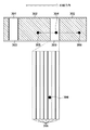
図3はシートに記録される画像と記録品位保持パターンの一例を示す図である。 FIG. 3 is a diagram showing an example of an image recorded on a sheet and a recording quality holding pattern.
この実施例では、シートに画像を記録する際に、画像データと記録品位保持パターンのデータを組み合わせた記録データを作成して記録を行う。その際の記録データの構成と、その特性について説明する。 In this embodiment, when recording an image on a sheet, recording data is created by combining image data and recording quality holding pattern data. The configuration and characteristics of the recording data at that time will be described.
図3は記録データがシートに記録される状態を図示している。図3に示すようにシートに対して記録を行う前に記録装置が記録する画像のレイアウトを作成する。図3はその画像レイアウトの1例を示している。後述する記録データのレイアウトが図3のような配置の画像が記録されるようにデータを作成する。 FIG. 3 illustrates a state in which the recording data is recorded on the sheet. As shown in FIG. 3, an image layout to be recorded by the recording apparatus is created before recording on the sheet. FIG. 3 shows an example of the image layout. Data is created so that an image having a layout of recording data to be described later is recorded as shown in FIG.
図3において、301は記録装置のエンジン制御部208などを用いて処理が行われ記録を行うシート、302はエンジン制御部208によってシート301に記録される画像のレイアウト、303は記録品位保持のパターン(以下、予備吐パターン)である。図3に示す画像配置は一例に過ぎず、画像処理部207等において画像のレイアウトが決定される。図3の例は、シート301の幅に対して同様な画像サイズを記録した場合の例である。
In FIG. 3,
図3に示すように、予備吐パターン303は画像302の間に挟まるようにレイアウトされている。予備吐パターンの記録は、画像302の記録に全ての記録ヘッドのノズルが使用されているかわからないため、次の画像を記録する前に、記録品位を保持するために行う処理である。そのため、図3からわかるように画像302の間に予備吐パターン303がレイアウトされている。このようにすることで画像302を一つ記録するたびに、予備吐パターン303を記録する事で記録ヘッドの状態をリセットし、次の画像302を、高品位に記録することができる。
As shown in FIG. 3, the
さらに304、305、306は同じノズルを使用する画素を示しており、画素304は予備吐パターンの一画素を示し、画素305、306は各々画像の中の画素を示している。この例では、画素304、305、306の間ではこれらの画素の記録に用いられたノズルは使用していないものとする。この場合、画素305と画素306との間では予備吐による画素304の記録以外はノズルを使用しないことになる。そのため、画素305の記録にノズルが使用された後、画素304を記録せずに画素306を記録した場合と、予備吐パターンの記録で画素304の記録に一度ノズルを使用後に画素306を記録する場合とでは記録品位の面では後者がより高品位となる。
Furthermore, 304, 305, and 306 indicate pixels that use the same nozzle, the
また、この場合に画素304を記録せずとも画素305と画素306との間が十分に記録品位が保てる距離であった場合には予備吐パターンで画素304の記録を行う必要がなくなる。こうすると予備吐パターンを画像の間に配置しなくてもよい場合が画像302の状態によっては発生する。それらの具体例と効果を次に示す。
In this case, if the distance between the
図4は図3で説明した記録データが実際にシートに記録される例を示す図である。 FIG. 4 is a diagram showing an example in which the recording data described in FIG. 3 is actually recorded on a sheet.
図4において、(a)は記録ヘッド307(図1のヘッドユニット105に相当)からシート308にインク312を吐出して画像309、310、311を記録する様子を示している。(a)の状態は、吐出されたインク312により画像309を記録している時点を示している。図3と図4とを関係づけると、画像309、311は画像302に対応し、画像310は予備吐パターン303に対応している。
4A shows a state in which
このような関係において、図3で予備吐パターン303を記録しなかった場合には、図4(a)において、予備吐パターンの画像310の記録を省略した場合と同等となる。つまり、図4(b)に示すように画像311の次に画像309を前にずらして記録する事になる。これは、図4(a)の予備吐パターンの画像310がなかった場合は、図4(c)で示すように、画像309はすでに記録が終了し、次に画像313の記録に進んでいる状態になる。
In such a relationship, if the
その結果、予備吐パターンが少ないほど、記録できる画像は増加し、また単位時間における画像記録数も増える。つまり、予備吐パターンを削減することは記録スループットの向上につながる。つまり、画像品位向上のために予備吐パターンを記録する必要がある一方で、記録のスループットが低下するというデメリットが生じることがわかる。従って、状況に応じて予備吐パターンの記録を削減することが記録スループット向上のために効果的であると言える。 As a result, the smaller the preliminary ejection pattern, the more images that can be recorded, and the greater the number of image recordings per unit time. That is, reducing the preliminary ejection pattern leads to an improvement in recording throughput. That is, it is necessary to record the preliminary ejection pattern for improving the image quality, but there is a disadvantage that the recording throughput is reduced. Therefore, it can be said that reducing the recording of the preliminary ejection pattern according to the situation is effective for improving the recording throughput.
<記録処理>
1.全体概要
図5は記録処理の概要を示すフローチャートである。
<Recording process>
1. Overall Overview FIG. 5 is a flowchart showing an overview of recording processing.
まず、ステップS401では記録装置は、接続されたPC等からジョブと呼ばれる印刷指示データであるジョブデータを受信する。このジョブデータ受信の詳細は図6を参照して後述する。 First, in step S401, the recording apparatus receives job data, which is print instruction data called a job, from a connected PC or the like. Details of this job data reception will be described later with reference to FIG.
ジョブデータを受信後、ステップS402では、記録データを作成する。印刷ジョブについてはジョブ毎に属性が異なるが、この実施例での記録は連続シートへの記録であるため、連続シートへの記録用にジョブの画像データを再配置して、画像処理を行ってから記録を実行する必要がある。そのため、受信ジョブデータに基づいて記録データを作成するのである。また、図3〜図4で示した予備吐パターンの配置についてはステップS402における記録データ作成時に画像間に配置することで対応する。この詳細な説明は図7を参照して後述する。 After receiving the job data, in step S402, recording data is created. The print job has different attributes for each job, but since the recording in this embodiment is recording on a continuous sheet, the image data of the job is rearranged for recording on the continuous sheet, and image processing is performed. It is necessary to perform recording from. Therefore, recording data is created based on the received job data. The preliminary ejection patterns shown in FIG. 3 to FIG. 4 are arranged by arranging them between images when creating the recording data in step S402. This detailed description will be described later with reference to FIG.
ステップS403では、ステップS402において作成した記録データに基づいてシートに画像を記録する。 In step S403, an image is recorded on the sheet based on the recording data created in step S402.
このようにして、記録装置はシートに対して受信したジョブを連続的に記録する事ができる。 In this way, the recording apparatus can continuously record received jobs on sheets.
2.ジョブデータ受信の詳細
図6は図5のステップS401のジョブデータ受信の詳細な処理を示すフローチャートである。
2. Details of Job Data Reception FIG. 6 is a flowchart showing detailed processing of job data reception in step S401 of FIG.
まず、ステップS501では、記録装置がジョブ受信可能かどうか確認する。ここで、ジョブ受信可能でなければジョブ受信可能になるまで処理を待ち合わせる。そして、ジョブ受信可能となった場合に、記録装置はジョブ受信を自動的に開始する。記録装置にとって、ジョブ受信は受動的なものであるため、図6にジョブ受信のステップは記載されていないが、このタイミングでジョブ受信を行う。 First, in step S501, it is confirmed whether the recording apparatus can receive a job. If the job cannot be received, the process waits until the job can be received. When the job can be received, the recording apparatus automatically starts job reception. Since the job reception is passive for the recording apparatus, the job reception step is not shown in FIG. 6, but the job reception is performed at this timing.
次にステップS502では、1ジョブ分のデータを受信終了したかどうかを確認する。ここで、1ジョブ分が受信終了まで処理を待ち合わせ、1ジョブ分のデータ受信終了を確認した時点で処理はステップS503に進む。ステップS503では、受信した1ジョブのデータに対して、RIP処理を実行する。このRIP処理によって、ジョブに含まれる画像データが画像処理される。ここでジョブ内の画像を1画像ずつに分けて、連続シートに記録するのに使用する。 In step S502, it is confirmed whether or not reception of data for one job has been completed. Here, the process waits until the reception of one job is completed, and the process proceeds to step S503 when the data reception completion of one job is confirmed. In step S503, RIP processing is executed on the received data of one job. Image data included in the job is subjected to image processing by this RIP processing. Here, the images in the job are divided into images and used for recording on a continuous sheet.
その後、処理はステップS504において、RIP処理後の画像データを用いてシートに記録させる順番で画像毎に、対応する画像データを一時保存領域に保存する。この実施例では、一時保存領域はHDD204にパーティションを設けて一時保存領域として専用の領域を設けて使用する。しかし、同様の目的を達成できるのであれば、他の方法を用いても良い。
Thereafter, in step S504, the process stores the corresponding image data in the temporary storage area for each image in the order of recording on the sheet using the image data after the RIP process. In this embodiment, the temporary storage area is used by providing a partition in the
次にステップS505では、ステップS504において一時保存領域に保存した画像データ群の情報に基づいて、記録の開始条件を満たしているかを調べる。この実施例では一時保存領域に、用意された連続シートの長さに相当する画像データが保存された場合に、記録開始条件を満たすとしている。しかしながら、このフローチャートに示すように、記録開始条件を満たすのであれば、前記条件の限りではない。ここで、まだ記録開始条件を満たしていないと判断された場合には、処理はステップS502へ戻る。これに対して、印刷開始条件を満たしていると判断された場合には、この処理を終了する。 Next, in step S505, based on the information of the image data group stored in the temporary storage area in step S504, it is checked whether the recording start condition is satisfied. In this embodiment, it is assumed that the recording start condition is satisfied when image data corresponding to the length of the prepared continuous sheet is stored in the temporary storage area. However, as shown in this flowchart, as long as the recording start condition is satisfied, the condition is not limited. If it is determined that the recording start condition is not yet satisfied, the process returns to step S502. On the other hand, if it is determined that the print start condition is satisfied, this process is terminated.
そして、処理は図5に示したステップS402の処理に進む。 And a process progresses to the process of step S402 shown in FIG.
3.記録データ作成の詳細
図7は図5のステップS402の記録データ作成の詳細な処理を示すフローチャートである。図6を参照して説明したように、一時保存領域に記録用の画像データが保存されている。そして、その保存データ量が記録開始条件を満たした場合、以下の処理を実行して記録データを作成する。
3. Details of Recording Data Creation FIG. 7 is a flowchart showing detailed processing of recording data creation in step S402 of FIG. As described with reference to FIG. 6, image data for recording is stored in the temporary storage area. When the stored data amount satisfies the recording start condition, the following processing is executed to create recording data.
まず、ステップS601では、画像の番号Nを初期化してN=1とする。次にステップS602では、一時保存領域のN番目の画像を表現する画像データを記録データとして追加する。この追加は、記録データとして別に保存領域を設け、そこに追加した事を意味しており、そのデータをそのまま記録に用いることを想定したデータ群となっている。ステップS602で記録データにN番目の画像を表現する画像データを追加した後、処理はステップS603において、画像Nの後に予備吐パターンが必要であるかを確認する。 First, in step S601, the image number N is initialized to N = 1. In step S602, image data representing the Nth image in the temporary storage area is added as recording data. This addition means that a separate storage area is provided as recording data and added thereto, and this data group assumes that the data is used for recording as it is. After adding image data representing the Nth image to the recording data in step S602, the process confirms whether a preliminary ejection pattern is necessary after the image N in step S603.
この条件判断における条件については、図8/図10を参照して後で詳細に説明する。図8/図10に示した条件により、予備吐パターンの記録が必要であると判断されたら、処理はステップS604へ進む。ステップS604では、予備吐パターンを記録データに追加する。どのように予備吐パターンを追加するかについては、後で図19を参照して詳細に説明する。 The conditions for this condition determination will be described later in detail with reference to FIGS. If it is determined that the preliminary ejection pattern needs to be recorded according to the conditions shown in FIGS. 8 and 10, the process proceeds to step S604. In step S604, the preliminary ejection pattern is added to the recording data. How to add the preliminary ejection pattern will be described later in detail with reference to FIG.
ステップS604では、画像Nに対応する画像データを記録データに追加後、その結果に応じて予備吐パターンのデータが追加される。その追加後、処理はステップS605に進む。一方、ステップS603において予備吐パターンの記録が不要と判断された場合には、処理はそのままステップS605に進む。 In step S604, after the image data corresponding to the image N is added to the recording data, the preliminary ejection pattern data is added according to the result. After the addition, the process proceeds to step S605. On the other hand, if it is determined in step S603 that recording of the preliminary ejection pattern is unnecessary, the process proceeds to step S605 as it is.
ステップS605では、一時保存領域に保存されている画像データの内、N番目の画像に対応する画像データを「処理済」に変更する。これは一時保存領域に保存されている画像データには「処理前」か「処理済」かの情報が付加されており、この情報を「処理済」にする事で、記録データにその画像データが使用されて配置されている事を示す。 In step S605, the image data corresponding to the Nth image among the image data stored in the temporary storage area is changed to “processed”. This is because the image data stored in the temporary storage area is added with the information “Before processing” or “Processed”. By setting this information to “Processed”, the image data is added to the recorded data. Indicates that is used and placed.
次にステップS606では、一時保存領域の画像データの内、「処理済」になっていない画像データがあるかどうかを確認する。ここで、一時保存領域に「処理前」の画像データがなければこの処理を終了する。これに対して、まだ「処理前」の画像データがあれば、処理はステップS607に進み、Nの値を+1インクリメントして、ステップS602に戻る。 In step S606, it is checked whether there is image data that is not “processed” among the image data in the temporary storage area. Here, if there is no “pre-processing” image data in the temporary storage area, this processing ends. On the other hand, if there is still “before processing” image data, the process proceeds to step S607, the value of N is incremented by +1, and the process returns to step S602.
このようにして、一時保存領域に保存された画像データを記録データに予備吐パターンも含めて配置していく事ができる。 In this way, it is possible to arrange the image data stored in the temporary storage area including the preliminary discharge pattern in the recording data.
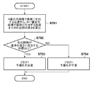
4.予備吐出の要/不要の判断
図8は各画像毎に全ノズルを使用して記録する場合に画像品位保持用の予備吐出が必要か不必要かの条件判断の処理を示すフローチャートである。このフローチャートは、図7のステップ603において予備吐が必要か否かを判別する処理の詳細を示している。この実施例では、予備吐出要否の条件判断を記録ヘッドの各ノズルに対して行う。この説明で、Nは図7で言及した画像の順番として同じものを指す。
4). Determination of Necessity / Necessary of Preliminary Discharge FIG. 8 is a flowchart showing a process for determining whether or not preliminary discharge for maintaining image quality is necessary or not when printing is performed using all nozzles for each image. This flowchart shows details of processing for determining whether or not preliminary ejection is necessary in step 603 of FIG. In this embodiment, the condition determination of whether or not preliminary ejection is necessary is performed for each nozzle of the recording head. In this description, N indicates the same image order referred to in FIG.
まず、ステップS701では、実際に記録動作を行う場合に記録されるであろう記録媒体上の、画像Nで最後に吐出する画素の位置から、画像N+1で最初に吐出する画素の位置までのノズルが未使用となる間の長さを算出する。具体的には画像Nで最後に吐出する画素の座標と、画像N+1でそのノズルの吐出を必要とする画素の座標とから間の長さを算出することができる。この長さは図3で例示した画素305と画素306の間隔に相当する。ここで、算出する長さは、画像間に全ノズルにおいて予備吐パターンを記録することを前提として算出する。
First, in step S701, nozzles from the position of the last pixel to be ejected in the image N to the position of the first pixel to be ejected in the image N + 1 on the recording medium that will be recorded when actually performing the recording operation. Calculate the length during which is unused. Specifically, it is possible to calculate the length between the coordinates of the pixel to be ejected last in the image N and the coordinates of the pixel that requires ejection of the nozzle in the image N + 1. This length corresponds to the interval between the
次に、ステップS702においてシートの搬送速度から決まる基準値とノズルが未使用となる間の長さとを比較する。ここで、基準値とはシートの搬送速度を予め決められた時間で割った長さをさす。予め決められた時間とは、ノズルの乾燥を防ぐために一定時間毎に吐出を行う際の一定時間間隔をさす。 In step S702, the reference value determined from the sheet conveyance speed is compared with the length during which the nozzle is not used. Here, the reference value refers to a length obtained by dividing the sheet conveyance speed by a predetermined time. The predetermined time refers to a certain time interval when discharging is performed every certain time in order to prevent the nozzle from drying.
図9は基準値について説明する図である。図9において、画素305と画素306の間隔はシート搬送速度によって決まる基準値の長さを示す。
FIG. 9 is a diagram for explaining the reference value. In FIG. 9, the interval between the
また、図9において、(a)はシート搬送速度がS1の場合を示している。さて、(b)に示すように、シート搬送速度がS2(>S1)の場合は、基準値が(a)に示す基準値より長くなる。また、(c)に示すように、シート搬送速度がS3(<S1)の場合は基準値が(a)に示す基準値より短くなる。 In FIG. 9, (a) shows the case where the sheet conveying speed is S1. As shown in (b), when the sheet conveyance speed is S2 (> S1), the reference value is longer than the reference value shown in (a). As shown in (c), when the sheet conveyance speed is S3 (<S1), the reference value is shorter than the reference value shown in (a).
このように図9で示される基準値の変化から分かるように、ステップS702では画素305と画素306の記録間隔が図9(a)で示された基準の長さに相当する時間以上となる場合はノズルが乾燥してしまう時間より長い時間にわたりインクが吐出されない。このため、処理はステップS703に進んで、そのノズルには予備吐が必要であると判断する。これに対して、画素305と306が図9(a)で示された基準値の長さより短い間隔の場合はノズルが乾燥してしまう時間より短いタイミングでインクが吐出されるため、処理はステップS704に進んで、そのノズルには予備吐が不必要であると判断する。
As can be seen from the change in the reference value shown in FIG. 9, the recording interval between the
以上説明した処理により、全ノズルに対して画像Nの後に予備吐が必要か否かを判断する。 By the processing described above, it is determined whether or not preliminary ejection is necessary after the image N for all nozzles.
このようにノズル未使用の時間に相当する長さから予備吐の要否を判断することで、サイズが異なる画像が混在し予備吐パターンを記録可能な位置が不定であっても、基準値を超えずに的確に効率よく予備吐を行うことができる。 By determining whether or not preliminary ejection is necessary based on the length corresponding to the nozzle unused time in this way, even if images having different sizes are mixed and the position where the preliminary ejection pattern can be recorded is indefinite, the reference value is set. Pre-discharge can be performed accurately and efficiently without exceeding.
図10は各画像記録毎に吐出動作が必要ではないノズルがある場合に、各ノズルにおいて画像品位保持用の予備吐出が必要か不必要かの条件判断の処理を示すフローチャートである。このフローチャートは、図7のステップ603において予備吐が必要か否かを判別する処理の詳細を示している。この実施例では、予備吐出要否の条件判断を記録ヘッドの各ノズルに対して行う。この説明でも、Nは図7で言及した画像の順番として同じものを指す。なお、図10において、既に図8を参照して説明したのを同じ処理ステップについては同じステップ参照番号を付し、その説明は省略する。 FIG. 10 is a flowchart showing a process for determining whether or not preliminary ejection for maintaining image quality is necessary or not at each nozzle when there is a nozzle that does not require an ejection operation for each image recording. This flowchart shows details of processing for determining whether or not preliminary ejection is necessary in step 603 of FIG. In this embodiment, the condition determination of whether or not preliminary ejection is necessary is performed for each nozzle of the recording head. In this description as well, N indicates the same image order referred to in FIG. In FIG. 10, the same processing steps as those already described with reference to FIG. 8 are denoted by the same step reference numerals, and the description thereof is omitted.
まずステップS901では、実際に記録動作を行う場合に記録されるであろう記録媒体上の、画像Nの記録までにノズルで吐出を必要とする画素の最後の位置から画像N+1でそのノズルの吐出を必要とする位置までのノズルが未使用となる間の長さを算出する。この長さ算出では、画像Nの記録後に全ノズルにおいて予備吐パターンを記録することを前提とし、画像N+1までにノズルが未使用となる間の長さの合計値を求める。 First, in step S901, the ejection of the nozzle in the image N + 1 from the last position of the pixel that needs to be ejected by the nozzle until the recording of the image N on the recording medium that will be recorded when the recording operation is actually performed. The length during which the nozzles up to the position that requires is unused is calculated. This length calculation is based on the premise that the preliminary ejection pattern is recorded for all nozzles after the image N is recorded, and the total value of the lengths during which the nozzles are not used up to the image N + 1 is obtained.
ここで、ノズル未使用となる間の長さの算出方法について図面を参照して説明する。 Here, a method of calculating the length while the nozzle is not used will be described with reference to the drawings.
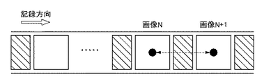
図11は、ノズル未使用の区間の長さの算出の様子を模式的に示す図である。 FIG. 11 is a diagram schematically illustrating how the length of the nozzle unused section is calculated.
図11において、画像Nにおける記録方向の辺の長さをN長、画像N+1における記録方向の辺の長さをN+1長とする。また、画像Nと画像N+1の間に全ノズルで吐出を行う予備吐パターンにおける記録方向の辺の長さをY幅とする。記録方向に関する画像Nの画素終端までにノズルが使用されていない長さの合計値をLとする。これらの4つの値を使って長さ算出を行う。具体的には画像Nの記録までにノズルで吐出される画素の座標と、画像N+1でそのノズルの吐出を必要とする画素の座標とから間の長さを算出することができる。なお、その詳細については、図12〜図15Fを参照して後述する。 In FIG. 11, the length of the side in the recording direction in the image N is N length, and the length of the side in the recording direction in the image N + 1 is N + 1 length. In addition, the length of the side in the recording direction in the preliminary ejection pattern in which ejection is performed with all nozzles between the image N and the image N + 1 is defined as Y width. Let L be the total value of the lengths in which the nozzles are not used up to the end of the pixel of the image N in the recording direction. The length is calculated using these four values. Specifically, the length between the coordinates of the pixels ejected by the nozzles until the recording of the image N and the coordinates of the pixels that require ejection of the nozzles in the image N + 1 can be calculated. Details thereof will be described later with reference to FIGS. 12 to 15F.
さて、ノズルが未使用となる間の長さを算出した後、ステップS702ではシートの搬送速度から決まる基準値とステップ901で求めた長さを比較する。そして、ステップS702〜S704では、その比較結果に従って、予備吐が必要であるか、或いは、不要であるかを判断する。 Now, after calculating the length during which the nozzles are not used, in step S702, the reference value determined from the sheet conveyance speed is compared with the length obtained in step 901. In steps S702 to S704, it is determined whether preliminary ejection is necessary or unnecessary according to the comparison result.
予備吐の要否判定後、処理はステップ902において、N番目以降の画像でノズル未使用となる間の長さ算出を行う。これは必要に応じて画像N+1の記録までにノズル未使用となる間の長さの合計値を算出することでなされる。そして、ノズル毎に、その結果を一時保存領域に記憶する。 After determining whether or not preliminary ejection is necessary, the process calculates the length of the Nth and subsequent images while the nozzle is not used in step 902. This is done by calculating the total length of the nozzles that are not used before the image N + 1 is recorded as necessary. The result is stored in the temporary storage area for each nozzle.
ステップ902の処理の詳細は図14を参照して後述する。 Details of the processing in step 902 will be described later with reference to FIG.
以上の方法により、各画像毎に吐出動作を必要としないノズルがある場合に、全ノズルに対して画像Nの記録後に予備吐が必要か否かを判断する。 By the above method, when there is a nozzle that does not require an ejection operation for each image, it is determined whether or not preliminary ejection is necessary after recording the image N for all nozzles.
図12は予備吐の要否の判定前に行う画像N+1までにノズルが使用されていない長さを算出する処理を示すフローチャートである。このフローチャートは図10のステップS901の処理の詳細に説明するものである。この処理では、画像Nの記録後に予備吐せずに画像N+1まで記録しても基準値を超えないかどうかを判定するための長さを求める。また、この処理はノズル毎に実行される。この長さは、画像Nの記録後に全ノズルを用いて予備吐パターンを記録する場合のY幅を含めた長さとする。 FIG. 12 is a flowchart showing a process for calculating a length in which the nozzle is not used up to an image N + 1, which is performed before determining whether or not preliminary ejection is necessary. This flowchart explains the details of the processing in step S901 in FIG. In this process, after recording the image N, a length for determining whether or not the reference value is exceeded even if the image N + 1 is recorded without preliminary ejection is obtained. This process is executed for each nozzle. This length is a length including the Y width when the preliminary ejection pattern is recorded using all the nozzles after the image N is recorded.
まず、ステップS1101では。対象のノズルにおいて画像Nでインク吐出をするかどうかを調べる。次に、ステップS1101の判断結果によらず、次のステップS1102およびステップS1105では、画像N+1でインクを吐出するかどうかを調べる。この2つの判断結果により、これに続く処理では、ノズルを使用していない2点間の長さを算出する。 First, in step S1101. It is checked whether or not ink is ejected from the image N at the target nozzle. Next, whether or not ink is ejected in the image N + 1 is checked in the next step S1102 and step S1105 regardless of the determination result in step S1101. Based on these two determination results, the length between two points not using the nozzle is calculated in the subsequent processing.
図13は様々な条件における長さの例を示す図である。 FIG. 13 is a diagram showing examples of lengths under various conditions.
ステップS1102において、画像N+1でインク吐出ありと判断された場合、画像Nと画像N+1の両方でインク吐出を必要とする画素が存在することになる。この場合、処理はステップS1103に進み、画像Nで最後に吐出する位置から画像N+1で最初に吐出する位置までの吐出間の長さを算出する。これは図8のステップS701の処理と同様である。 If it is determined in step S1102 that there is ink ejection in image N + 1, there are pixels that require ink ejection in both image N and image N + 1. In this case, the process proceeds to step S1103, and the length between discharges from the position at which the image N is finally discharged to the position at which the image N + 1 is first discharged is calculated. This is the same as the processing in step S701 in FIG.
図13(a)は、画像Nと画像N+1の両方でインク吐出を必要とする画素が存在する場合の長さを示す。この場合の長さは、画像Nで最後に吐出する位置から予備吐パターンの開始位置までと、Y幅と、予備吐パターン終了位置から画像N+1で最初に吐出する位置までの3つの長さを加えることで算出する。 FIG. 13A shows the length when pixels that require ink ejection exist in both the image N and the image N + 1. The length in this case is three lengths from the last ejection position in the image N to the start position of the preliminary ejection pattern, the Y width, and the preliminary ejection pattern end position to the first ejection position in the image N + 1. Calculate by adding.
次に、ステップS1102において、画像N+1で吐出なしと判定された場合、画像Nではインク吐出があり画像N+1ではインク吐出なしとなる。この場合、処理はステップS1104に進み、画像Nで最後に吐出する位置から画像N+1の全画素を記録する位置までのノズルを使用しない長さを算出する。 Next, when it is determined in step S1102 that there is no ejection in the image N + 1, there is ink ejection in the image N and no ink ejection in the image N + 1. In this case, the process proceeds to step S1104, and the length from the position at which the image N is finally ejected to the position at which all the pixels of the image N + 1 are recorded is calculated.
図13(b)は、画像Nではインク吐出があり画像N+1ではインク吐出なしの場合の長さを示す。この場合の長さは、画像Nで最後に吐出する位置から予備吐パターンの開始位置までと、Y幅と、N+1長の3つの長さを加えることで算出する。 FIG. 13B shows the length when ink is ejected in image N and no ink is ejected in image N + 1. The length in this case is calculated by adding three lengths, Y width and N + 1 length, from the last ejection position in image N to the start position of the preliminary ejection pattern.
さらに、ステップS1105において、画像N+1で吐出ありと判定された場合、画像Nでは吐出なしで画像N+1ではインク吐出を必要とする画素が存在することになる。この場合、処理はステップS1106に進み、画像Nまでのノズル未使用の長さの合計値に画像N+1で最初に吐出する位置までの長さを加えて吐出間の長さを算出する。 Furthermore, if it is determined in step S1105 that there is ejection in the image N + 1, there are pixels that require ejection in the image N + 1 without ejection in the image N. In this case, the process proceeds to step S1106, and the length up to the first ejection position in image N + 1 is added to the total value of the unused nozzle lengths up to image N to calculate the length between ejections.
図13(c)は、画像Nでは吐出なしで画像N+1ではインク吐出を必要とする画素が存在する場合の長さを示す。この場合の長さは、画像Nまでにノズル未使用の長さの合計Lと、Y幅と、予備吐パターン終了位置から画像N+1で最初に吐出する位置までの3つの長さを加えることで算出する。 FIG. 13C shows the length in the case where there is a pixel that requires no ink ejection in the image N and the ink that needs ink ejection in the image N + 1. The length in this case is obtained by adding the total length L of the unused nozzles up to the image N, the Y width, and the three lengths from the preliminary ejection pattern end position to the first ejection position in the image N + 1. calculate.
またさらに、ステップS1105において、画像N+1で吐出なしと判定された場合、画像Nと画像N+1の両方でインク吐出がないことになる。この場合、処理はステップS1107に進み、画像Nまでにノズル未使用の長さの合計値に画像N+1の全画素を記録する位置までのノズルを使用しない長さを算出する。 Furthermore, if it is determined in step S1105 that there is no ejection in image N + 1, there is no ink ejection in both image N and image N + 1. In this case, the process proceeds to step S1107, and the length that does not use the nozzles up to the position where all the pixels of the image N + 1 are recorded is calculated as the total length of the unused nozzles up to the image N.
図13(d)は、画像Nと画像N+1の両方でインク吐出がない場合の長さを示す。この場合の長さは、画像Nまでにノズル未使用の長さの合計Lと、Y幅と、N+1長の3つの長さを加えることで算出する。 FIG. 13D shows the length when there is no ink ejection in both the image N and the image N + 1. The length in this case is calculated by adding the total length L of unused nozzles up to the image N, the Y width, and the N + 1 length.
以上のようにして、基準値と比較するための長さを求め、図9のステップ702の処理を実行する。
As described above, the length for comparison with the reference value is obtained, and the process of
図14は予備吐の要否を判定後に実行する画像N+1までにノズル未使用となる長さ算出の詳細な処理を示すフローチャートである。このフローチャートは、図10のステップ902を詳細に説明するもので、N番目以降の画像でノズル未使用となる間の長さ算出を行うために処理する。また、この処理はノズル毎に実行され、予備吐判定結果を考慮して画像N+1までにノズル未使用となる長さを算出する。 FIG. 14 is a flowchart showing detailed processing for calculating a length in which the nozzles are not used up to an image N + 1 executed after determining whether or not preliminary ejection is necessary. This flowchart explains step 902 in FIG. 10 in detail, and performs processing to calculate the length while the nozzles are not used in the Nth and subsequent images. This process is executed for each nozzle, and the length of nozzles that are not used up to the image N + 1 is calculated in consideration of the preliminary ejection determination result.
図15A〜図15Fは、様々な条件における長さの例を示す図である。これらの図は図13で示した各条件において図14で示す処理を実行することで得られる合計値Lの具体的な例を示すものである。 15A to 15F are diagrams illustrating examples of lengths under various conditions. These figures show specific examples of the total value L obtained by executing the process shown in FIG. 14 under the conditions shown in FIG.
まず、ステップS1301では対象のノズルにおいて画像N+1で吐出をするかどうかを調べる。ここで、吐出をすると判断された場合、画像N+1の後の予備吐要否判定で必要な長さは画像N+1で最後に吐出した画素の位置より記録が後になる領域の値となる。従って、画像N以降で画像N+1までのノズルを使用しない長さの合計値を必要としない。この場合、処理はステップS1302に進み、積算してきた合計値Lを“0”にして初期化する。 First, in step S1301, it is checked whether or not ejection is performed with the image N + 1 at the target nozzle. Here, when it is determined that ejection is to be performed, the length necessary for determining whether or not preliminary ejection is necessary after the image N + 1 is a value of an area after recording from the position of the last ejected pixel in the image N + 1. Therefore, the total value of the lengths that do not use the nozzles up to image N + 1 after image N is not required. In this case, the process proceeds to step S1302, where the accumulated total value L is initialized to “0”.
処理がステップS1302に進む場合は、図13(a)と図13(c)に例示する場合に相当し、これらはそれぞれ図15Aと図15Dに例示する場合に該当する。図15Aと図15Dで示す通り合計値Lに積算するための値はない。 The case where the process proceeds to step S1302 corresponds to the case illustrated in FIGS. 13A and 13C, which corresponds to the case illustrated in FIGS. 15A and 15D, respectively. As shown in FIGS. 15A and 15D, there is no value to be added to the total value L.
これに対して、ステップS1301において、吐出をしないと判断された場合、画像N以降で画像N+1までのノズル未使用の間の長さの合計値Lを必要とする。従って、画像Nの記録後に予備吐があるか否かを考慮して、画像N+1までのノズル未使用の間の長さの合計値を算出する。この場合、処理はステップS1303に進み、図10のステップS702〜704での処理結果に基づき、画像Nの記録後に予備吐を行うか否かを調べる。ここで、画像Nの記録後に予備吐を行うと判断された場合、処理はステップS1304に進み、画像Nの記録後に予備吐を行わないと判断された場合、処理はステップS1305に進む。 On the other hand, if it is determined in step S1301 that ejection is not performed, a total value L of the lengths between nozzles unused after image N up to image N + 1 is required. Accordingly, in consideration of whether or not preliminary ejection occurs after the image N is recorded, the total length of the unused nozzles up to the image N + 1 is calculated. In this case, the process proceeds to step S1303, and it is checked whether or not preliminary ejection is performed after the image N is recorded based on the processing results in steps S702 to 704 in FIG. If it is determined that preliminary ejection is performed after the image N is recorded, the process proceeds to step S1304. If it is determined that preliminary ejection is not performed after the image N is recorded, the process proceeds to step S1305.
さて、ステップS1304では、画像Nの記録後で予備吐してから画像N+1を吐出し終わる位置までの長さを求める。従って、予備吐パターンを吐出する開始位置から画像N+1の吐出終了位置までの長さを、ノズル未使用の間の長さの合計値Lとして算出する。処理がステップS1304に進む場合は、図13(b)と図13(d)に例示するように画像Nの記録後で予備吐を行う場合に相当し、これらはそれぞれ図15Bと図15Eに例示する場合に該当する。図15Bと図15Eで示す通り、画像N+1の記録までに最後に吐出する位置は予備吐パターンであるため、Y幅とN+1長を画像N+1までのノズル未使用の間の長さの合計値Lとする。 In step S1304, the length from the preliminary ejection after recording the image N to the position where the image N + 1 is completely ejected is obtained. Therefore, the length from the start position at which the preliminary ejection pattern is ejected to the ejection end position of the image N + 1 is calculated as the total value L of the length when the nozzles are not used. The case where the process proceeds to step S1304 corresponds to the case where preliminary ejection is performed after recording of the image N as illustrated in FIGS. 13B and 13D, which are illustrated in FIGS. 15B and 15E, respectively. Applicable when As shown in FIGS. 15B and 15E, the final ejection position before the recording of the image N + 1 is the preliminary ejection pattern, and therefore the total value L of the Y width and the N + 1 length between the unused nozzles up to the image N + 1. And
これに対して、ステップS1305では、画像Nまでにノズル未使用の間の長さの合計値から画像N+1を記録終了位置までの長さを求める。この場合、図12の処理では画像Nの記録後に予備吐を行わない前提で長さを算出しており、ステップS1305の処理を行う条件と一致する。従って、図12の処理で求めた長さを、ノズル未使用の間の長さの合計値Lとする。 On the other hand, in step S1305, the length from the total length of the nozzles not used up to the image N to the recording end position of the image N + 1 is obtained. In this case, in the process of FIG. 12, the length is calculated on the premise that the preliminary ejection is not performed after the image N is recorded, which matches the condition for performing the process of step S1305. Accordingly, the length obtained in the process of FIG. 12 is set as a total value L of the lengths when the nozzles are not used.
処理がステップS1305に進む場合は、図13(b)と図13(d)に例示するように画像Nの記録後で予備吐を行わない場合、これらはそれぞれ図15Cと図15Fに例示する場合に該当する。図15Cと図15Fで示す通り、画像N+1の記録までのノズル未使用の間の長さは図13(b)と図13(d)で求める長さと同じである。従って、画像Nまでのノズル未使用の間の長さの合計Lと、Y幅と、N+1長の3つの長さを加えた値が合計値Lとなり、図12の値をそのまま合計値Lとする。 When the process proceeds to step S1305, as illustrated in FIGS. 13B and 13D, when the preliminary ejection is not performed after recording of the image N, these are illustrated in FIGS. 15C and 15F, respectively. It corresponds to. As shown in FIGS. 15C and 15F, the length of the unused nozzle until the recording of the image N + 1 is the same as the length obtained in FIGS. 13B and 13D. Therefore, a total value L is obtained by adding the total length L of the nozzles not used up to the image N, the Y width, and the three lengths of N + 1, and the value in FIG. To do.
最後に算出した合計値Lは、画像N以降の算出で使用するためにステップS1306で一時保存領域に保存する。 The finally calculated total value L is stored in the temporary storage area in step S1306 for use in the calculation after the image N.
以上説明した処理により、図10の予備吐の要否判定(ステップS702)の後処理を行い、一連の予備吐の要否判定処理を終了する。 Through the processing described above, post-processing for determining whether or not preliminary ejection is necessary (step S702) in FIG. 10 is performed, and a series of preliminary ejection necessity determination processing is completed.
以上、図8〜図15Fを参照して説明した処理により、ノズル未使用となる間の長さから各ノズルの予備吐の要否を判断することができる。 As described above, by the processing described with reference to FIGS. 8 to 15F, it is possible to determine whether or not the preliminary ejection of each nozzle is necessary from the length during which the nozzle is not used.
次に、さらに、図8〜図15Fにおいて予備吐の要否を判定した結果によって、予備吐パターンをシート搬送方向に短くできる例について図16〜図18を参照して説明する。 Next, an example in which the preliminary ejection pattern can be shortened in the sheet conveyance direction based on the determination result of the necessity of preliminary ejection in FIGS. 8 to 15F will be described with reference to FIGS.
図16は予備吐の要否を判定した結果、吐出を行う記録ヘッドの一部が予備吐不要となる場合の画像レイアウトを示す図である。 FIG. 16 is a diagram illustrating an image layout in a case where it is determined whether or not preliminary ejection is necessary, and thus a part of the recording head that performs ejection does not require preliminary ejection.
図16に示すように、画像Nと画像N+1の間の予備吐パターンにおいて、例えば、7つあるフルライン記録ヘッドのうち3つの記録ヘッドの全てのノズルにおいて予備吐出が否であると判定され、予備吐を行う必要がない場合がある。この場合には、予備吐パターンの領域を3ライン分減らすことができる。これにより、後続の画像N+1の記録開始位置をシートの搬送方向に関し、より前に進めることができる。 As shown in FIG. 16, in the preliminary ejection pattern between the image N and the image N + 1, for example, it is determined that preliminary ejection is not possible in all the nozzles of three recording heads out of seven full line recording heads. There may be no need to perform preliminary discharge. In this case, the preliminary ejection pattern area can be reduced by three lines. Thereby, the recording start position of the subsequent image N + 1 can be advanced further in the sheet conveyance direction.
図17は予備吐の要否を判定した結果、吐出を行う全ての記録ヘッドの全てのノズルにおいて予備吐が否であると判定され、全ての記録ヘッドから予備吐出不要となった場合の画像レイアウトを示す図である。図17に示すように、画像Nと画像N+1の間の予備吐パターンにおいて、例えば、7つあるフルライン記録ヘッドのうち7つ全てが予備吐を必要としない場合、予備吐パターンを省略する。これにより、後続の画像N+1を画像Nに連続して記録することができる。つまり、1つの記録ヘッドの全てのノズルにおいて予備吐出否であると判定された場合には、その記録ヘッドの予備吐パターンを省略することができる。 FIG. 17 shows an image layout when it is determined that preliminary ejection is not required for all nozzles of all recording heads that perform ejection as a result of determining whether or not preliminary ejection is necessary, and preliminary ejection is not required from all recording heads. FIG. As shown in FIG. 17, in the preliminary ejection pattern between the image N and the image N + 1, for example, when all seven of the seven full line recording heads do not require preliminary ejection, the preliminary ejection pattern is omitted. As a result, the subsequent image N + 1 can be continuously recorded on the image N. That is, when it is determined that preliminary ejection is not possible for all the nozzles of one recording head, the preliminary ejection pattern of that recording head can be omitted.
図18は画像N+nまでの記録方向の合計長が、全ての記録ヘッドにおいて予備吐の要否を判定するための基準値より短い場合の画像レイアウトを示す図である。この場合、図18に示すように、画像Nからn個分までを全ての記録ヘッドから予備吐なしに連続して記録する。これにより、画像n+1個分を連続して記録することができる。 FIG. 18 is a diagram showing an image layout when the total length in the recording direction up to the image N + n is shorter than a reference value for determining whether or not preliminary ejection is necessary in all the recording heads. In this case, as shown in FIG. 18, n images from the image N are continuously recorded from all the recording heads without preliminary ejection. As a result, n + 1 images can be recorded continuously.
以上、図8〜図18を参照して説明した処理によって、図7のステップS603において予備吐の要否を各ノズルに対して判定をすることで必要最低限の吐出が実現する。 As described above, by the processing described with reference to FIGS. 8 to 18, the minimum necessary ejection is realized by determining whether or not preliminary ejection is necessary in step S <b> 603 in FIG. 7.
なお、この実施例では記録ヘッドのノズル毎に判定を行うが、ノズルブロック毎にその判定を行ってもよい。そして、図17または図18に示すように、画像Nの記録後に予備吐パターンの記録を省略できると判断された場合、図7における処理では、ステップS603からステップ605に進む。また、図16に例示する場合や図16〜図18のいずれにも当てはまらず1ラインごと予備吐を省略できない場合、図7における処理では、ステップS603からステップS604に進む。 In this embodiment, the determination is performed for each nozzle of the recording head, but the determination may be performed for each nozzle block. Then, as shown in FIG. 17 or 18, when it is determined that the recording of the preliminary ejection pattern can be omitted after the recording of the image N, the process in FIG. 7 proceeds from step S 603 to step 605. Further, in the case illustrated in FIG. 16 or in the case of any of FIGS. 16 to 18 and when the preliminary ejection cannot be omitted for each line, the process in FIG. 7 proceeds from step S603 to step S604.
最後に、ステップS604の詳細について説明する。 Finally, details of step S604 will be described.
図19はステップS604の詳細を示すフローチャートである。 FIG. 19 is a flowchart showing details of step S604.
まず、ステップS1801では、全てのフルライン記録ヘッドに「予備吐要」を示すフラグを設定する。 First, in step S1801, a flag indicating “Preliminary ejection required” is set for all full-line recording heads.
次に、ステップS1802では、各フルライン記録ヘッドが予備吐を省略できるものであるかどうかを調べる。ここで、図16で説明した方法によって予備吐を1つのフルライン記録ヘッドの全てのノズルについて省略できると判断される場合、処理はステップS1803に進む。これに対して、図16で説明した方法で1つのフルライン記録ヘッドの全てのノズルについて省略できないと判断された場合、処理はステップS1804に進む。 Next, in step S1802, it is checked whether each full line recording head can omit the preliminary ejection. Here, if it is determined that the preliminary ejection can be omitted for all the nozzles of one full-line recording head by the method described in FIG. 16, the process proceeds to step S1803. On the other hand, if it is determined that all the nozzles of one full line recording head cannot be omitted by the method described in FIG. 16, the process advances to step S1804.
ステップ1803では、省略できるフルライン記録ヘッドに対して「予備吐不要」を示すフラグに設定を変更し、その後、処理はステップS1804に進む。ステップS1804では、フラグに「予備吐要」と設定されたフルライン記録ヘッドにおいて、予備吐要否判定で予備吐が必要と判定されたノズルのみを対象に予備吐データを生成し、記録データに追加する。このように予備吐が必要のノズルにおいてのみ予備吐出パターンの記録を行うことで、消費されるインク量を削減することができる。このような処理により、画像Nの画像データ後に予備吐パターンのデータを追加した記録データを作成する。
In
なお1つのフルライン記録ヘッドのいずれか1つのノズルで予備吐が必要と判定された場合には、1つのフルライン記録ヘッドの全てのノズルから予備吐パターンで記録を行うように記録データを作成してもよい。このように全てのノズルから記録しておくことで、このフルライン記録ヘッドにおける次の予備吐パターンを省略できる可能性が生まれるためである。 If it is determined that any one nozzle of one full line recording head needs preliminary ejection, recording data is created so that recording is performed with a preliminary ejection pattern from all nozzles of one full line recording head. May be. This is because by recording from all the nozzles in this way, there is a possibility that the next preliminary ejection pattern in the full-line recording head can be omitted.
従って以上説明した実施例によれば、画像サイズが異なる複数の画像をフルライン記録ヘッドにより記録する場合、画像品位保持用のパターンを最低限必要な領域のみ記録することが可能になる。これにより、記録スループットを向上させつつ、画像品質を保つことができる。 Therefore, according to the embodiment described above, when a plurality of images having different image sizes are recorded by the full-line recording head, it is possible to record only a minimum necessary area for a pattern for maintaining image quality. Thereby, it is possible to maintain the image quality while improving the recording throughput.
Claims (10)
前記第1方向と交差する第2方向に沿ってノズルが複数形成され、記録データに基づいて当該複数のノズルからシートにインクを吐出するライン型記録ヘッドと、
ホスト装置から第1画像と当該第1画像に続く第2画像とを含む画像データが入力される入力手段と、を備える記録装置であって、
前記複数のノズルのそれぞれについて、前記第1画像の記録の完了前に最後にインクを吐出したシート上の位置から前記第2画像の記録の際に最初にインクを吐出するシート上の位置までの長さを算出する算出手段と、
前記算出手段による算出結果に基づいて、前記第1画像と前記第2画像の間に前記ライン型記録ヘッドによる予備吐出が必要であるか否かを判断する判断手段と、
前記判断手段により前記予備吐出が必要であると判断された場合、前記予備吐出のためのデータを前記画像データの前記第1画像と前記第2画像の間に追加して前記記録データを作成する作成手段と、を備え、
前記作成手段は、前記判断手段により前記予備吐出が必要でないと判断された場合、前記予備吐出のためのデータを前記第1画像と前記第2画像の間に追加せずに前記第1画像と前記第2画像の間を詰めて前記記録データを作成することを特徴とする記録装置。 A transport unit for transporting the sheet in the first direction;
A line type recording head in which a plurality of nozzles are formed along a second direction intersecting the first direction, and ink is ejected from the plurality of nozzles to a sheet based on recording data;
An input device for inputting image data including a first image and a second image following the first image from a host device,
For each of the plurality of nozzles, from the position on the sheet where ink was last ejected before completion of recording of the first image to the position on the sheet where ink is ejected first when recording the second image. A calculating means for calculating the length;
Based on by that calculation result to the calculating means, determining means for determining whether it is necessary to preliminary ejection by said line type recording head between the first image and the second image,
When the determination unit determines that the preliminary ejection is necessary, the recording data is created by adding data for the preliminary ejection between the first image and the second image of the image data. Creating means, and
It said generating means, when it is determined not to require the preliminary discharge by the determining means, the first image data for the preliminary ejection without adding between the first image and the second image A recording apparatus, wherein the recording data is created by filling a space between the second images .
前記作成手段は、前記複数のライン型記録ヘッドごとに前記予備吐出のためのデータを前記第1画像と前記第2画像の間に追加して前記記録データを作成することを特徴とする請求項1乃至7のいずれか1項に記載の記録装置。 A plurality of the line-type recording heads;
The creation unit adds the data for the preliminary ejection between the first image and the second image for each of the plurality of line-type recording heads to create the recording data. The recording apparatus according to any one of 1 to 7.
ホスト装置から第1画像と当該第1画像に続く第2画像とを含む画像データが入力される入力工程と、
前記複数のノズルのそれぞれについて、前記第1画像の記録の完了前に最後にインクを吐出したシート上の位置から前記第2画像の記録の際に最初にインクを吐出するシート上の位置までの長さを算出する算出工程と、
前記算出工程における算出結果に基づいて、前記第1画像と前記第2画像の間に前記ライン型記録ヘッドによる予備吐出が必要であるか否かを判断する判断工程と、
前記判断工程で前記予備吐出が必要であると判断された場合、前記予備吐出のためのデータを前記画像データの前記第1画像と前記第2画像の間に追加して前記記録データを作成する作成工程と、を有し、
前記作成工程において、前記判断工程で前記予備吐出が必要でないと判断された場合、前記予備吐出のためのデータを前記第1画像と前記第2画像の間に追加せずに前記第1画像と前記第2画像の間を詰めて前記記録データを作成することを特徴とする記録データの作成方法。 Recording in a recording apparatus having a line type recording head in which a plurality of nozzles are formed along a second direction intersecting the first direction in which the sheet is conveyed and ink is ejected from the plurality of nozzles onto the sheet based on the recording data. A method for creating data,
An input process in which image data including a first image and a second image following the first image is input from the host device;
For each of the plurality of nozzles, from the position on the sheet where ink was last ejected before completion of recording of the first image to the position on the sheet where ink is ejected first when recording the second image. A calculation step for calculating the length;
Based on our Keru calculation result to the calculating step, a determination step of determining whether it is necessary to pre-ejection according to the first image and the line-type recording head between said second image,
When it is determined in the determination step that the preliminary ejection is necessary, the recording data is created by adding data for the preliminary ejection between the first image and the second image of the image data. A production process,
In the creating step, when it is determined that the preliminary discharge is not necessary in the determining step, said first image data for the preliminary ejection without adding between the first image and the second image A recording data creating method, wherein the recording data is created by filling a space between the second images .
Priority Applications (2)
| Application Number | Priority Date | Filing Date | Title |
|---|---|---|---|
| JP2012229240A JP6101038B2 (en) | 2012-10-16 | 2012-10-16 | Recording apparatus and recording data creation method |
| US14/039,022 US9073311B2 (en) | 2012-10-16 | 2013-09-27 | Printing apparatus and print control method |
Applications Claiming Priority (1)
| Application Number | Priority Date | Filing Date | Title |
|---|---|---|---|
| JP2012229240A JP6101038B2 (en) | 2012-10-16 | 2012-10-16 | Recording apparatus and recording data creation method |
Publications (3)
| Publication Number | Publication Date |
|---|---|
| JP2014079952A JP2014079952A (en) | 2014-05-08 |
| JP2014079952A5 JP2014079952A5 (en) | 2015-11-26 |
| JP6101038B2 true JP6101038B2 (en) | 2017-03-22 |
Family
ID=50474973
Family Applications (1)
| Application Number | Title | Priority Date | Filing Date |
|---|---|---|---|
| JP2012229240A Active JP6101038B2 (en) | 2012-10-16 | 2012-10-16 | Recording apparatus and recording data creation method |
Country Status (2)
| Country | Link |
|---|---|
| US (1) | US9073311B2 (en) |
| JP (1) | JP6101038B2 (en) |
Families Citing this family (9)
| Publication number | Priority date | Publication date | Assignee | Title |
|---|---|---|---|---|
| JP6641735B2 (en) * | 2015-06-19 | 2020-02-05 | カシオ計算機株式会社 | Printing apparatus, printing method, and program |
| JP6554966B2 (en) * | 2015-07-23 | 2019-08-07 | セイコーエプソン株式会社 | Liquid ejection device and head unit |
| JP6554965B2 (en) * | 2015-07-23 | 2019-08-07 | セイコーエプソン株式会社 | Liquid ejection device and method for controlling liquid ejection device |
| JP7059602B2 (en) * | 2017-12-06 | 2022-04-26 | 株式会社リコー | How to refresh the liquid discharge device and liquid discharge head |
| US10682857B2 (en) | 2018-06-26 | 2020-06-16 | Ricoh Company, Ltd. | Adaptive ink flushing of a printer |
| CN113286710A (en) | 2019-01-30 | 2021-08-20 | 惠普发展公司,有限责任合伙企业 | Security zone for maintenance tasks |
| AU2020272747B2 (en) * | 2019-04-12 | 2023-06-01 | Ball Corporation | Method of maintaining inkjet printhead meniscus |
| JP2022094553A (en) * | 2020-12-15 | 2022-06-27 | 東芝テック株式会社 | Inkjet head and method for driving the same |
| JP2022181879A (en) * | 2021-05-27 | 2022-12-08 | セイコーエプソン株式会社 | Printing device and method for producing printed matter |
Family Cites Families (13)
| Publication number | Priority date | Publication date | Assignee | Title |
|---|---|---|---|---|
| US5659342A (en) * | 1994-09-30 | 1997-08-19 | Hewlett-Packard Company | On-page inkjet printhead spitting system |
| JP2002144599A (en) | 2000-11-13 | 2002-05-21 | Canon Inc | Ink jet recorder and preliminary ejection method |
| JP2004168036A (en) | 2002-10-31 | 2004-06-17 | Canon Inc | Ink jet recording apparatus, drive control method therefor, control program and computer readable memory medium |
| JP2004167852A (en) * | 2002-11-20 | 2004-06-17 | Fuji Xerox Co Ltd | Ink-jet printer |
| US7357308B2 (en) | 2003-06-30 | 2008-04-15 | At&T Bls Intellectual Property, Inc. | System and method of automatically displaying patient information |
| JP3909714B2 (en) * | 2003-09-18 | 2007-04-25 | 富士フイルム株式会社 | Ink jet recording apparatus and preliminary discharge control method |
| US7407258B2 (en) * | 2004-09-13 | 2008-08-05 | Canon Finetech Inc. | Ink jet recording method, recording apparatus, and recorded object |
| JP4606101B2 (en) | 2004-09-13 | 2011-01-05 | キヤノンファインテック株式会社 | Paper surface pre-discharge method and ink jet recording apparatus |
| JP5014599B2 (en) | 2005-06-23 | 2012-08-29 | 大日本スクリーン製造株式会社 | Printing system, printing apparatus controller, printing processing execution method, and program |
| JP2008094007A (en) * | 2006-10-13 | 2008-04-24 | Canon Finetech Inc | Preliminary discharging method and inkjet image forming apparatus |
| US7806508B2 (en) | 2007-02-06 | 2010-10-05 | Fujifilm Corporation | Ink-jet recording method and ink-jet recording apparatus |
| US8757909B2 (en) * | 2010-06-18 | 2014-06-24 | Canon Kabushiki Kaisha | Image forming apparatus with cutting unit |
| JP2012006174A (en) | 2010-06-22 | 2012-01-12 | Canon Inc | Inkjet printing device, and inkjet printing method |
-
2012
- 2012-10-16 JP JP2012229240A patent/JP6101038B2/en active Active
-
2013
- 2013-09-27 US US14/039,022 patent/US9073311B2/en active Active
Also Published As
| Publication number | Publication date |
|---|---|
| US9073311B2 (en) | 2015-07-07 |
| US20140104334A1 (en) | 2014-04-17 |
| JP2014079952A (en) | 2014-05-08 |
Similar Documents
| Publication | Publication Date | Title |
|---|---|---|
| JP6101038B2 (en) | Recording apparatus and recording data creation method | |
| JP5743410B2 (en) | Printing control apparatus, method and program | |
| JP5814552B2 (en) | Image processing method and image processing apparatus | |
| EP2361777B1 (en) | Print control apparatus and print control method | |
| JP5300766B2 (en) | Printing control apparatus, method and program | |
| JP6114529B2 (en) | Recording apparatus and control method thereof | |
| JP5295151B2 (en) | Printing control apparatus, method and program | |
| JP2013086481A (en) | Printing control apparatus, method and program | |
| JP5783748B2 (en) | Printing control apparatus, method and program | |
| EP2437202B1 (en) | Print control apparatus and method | |
| JP2011218696A (en) | Print controller, method, and program | |
| JP5656968B2 (en) | Printing control apparatus, method and program | |
| JP6004630B2 (en) | Printing control apparatus, method and program | |
| JP5791297B2 (en) | Printing control apparatus, method and program | |
| JP5783744B2 (en) | Printing control apparatus, method and program | |
| JP5971919B2 (en) | Printing control apparatus, method and program | |
| JP5744558B2 (en) | Printing control apparatus, method and program | |
| JP5868472B2 (en) | Printing control apparatus, method and program | |
| JP6025314B2 (en) | Printing control apparatus, method and program | |
| JP5921140B2 (en) | Printing control apparatus, method and program | |
| JP5822885B2 (en) | Printing control apparatus, method and program | |
| JP5783745B2 (en) | Printing control apparatus, method and program | |
| JP5595076B2 (en) | Printing control apparatus, method and program |
Legal Events
| Date | Code | Title | Description |
|---|---|---|---|
| A521 | Request for written amendment filed |
Free format text: JAPANESE INTERMEDIATE CODE: A523 Effective date: 20151013 |
|
| A621 | Written request for application examination |
Free format text: JAPANESE INTERMEDIATE CODE: A621 Effective date: 20151013 |
|
| A977 | Report on retrieval |
Free format text: JAPANESE INTERMEDIATE CODE: A971007 Effective date: 20160713 |
|
| A131 | Notification of reasons for refusal |
Free format text: JAPANESE INTERMEDIATE CODE: A131 Effective date: 20160719 |
|
| A521 | Request for written amendment filed |
Free format text: JAPANESE INTERMEDIATE CODE: A523 Effective date: 20160920 |
|
| A131 | Notification of reasons for refusal |
Free format text: JAPANESE INTERMEDIATE CODE: A131 Effective date: 20161107 |
|
| A521 | Request for written amendment filed |
Free format text: JAPANESE INTERMEDIATE CODE: A523 Effective date: 20161226 |
|
| TRDD | Decision of grant or rejection written | ||
| A01 | Written decision to grant a patent or to grant a registration (utility model) |
Free format text: JAPANESE INTERMEDIATE CODE: A01 Effective date: 20170127 |
|
| A61 | First payment of annual fees (during grant procedure) |
Free format text: JAPANESE INTERMEDIATE CODE: A61 Effective date: 20170224 |
|
| R151 | Written notification of patent or utility model registration |
Ref document number: 6101038 Country of ref document: JP Free format text: JAPANESE INTERMEDIATE CODE: R151 |