JP6098728B2 - Data transfer apparatus, information processing apparatus, and data transfer method - Google Patents
Data transfer apparatus, information processing apparatus, and data transfer method Download PDFInfo
- Publication number
- JP6098728B2 JP6098728B2 JP2015541387A JP2015541387A JP6098728B2 JP 6098728 B2 JP6098728 B2 JP 6098728B2 JP 2015541387 A JP2015541387 A JP 2015541387A JP 2015541387 A JP2015541387 A JP 2015541387A JP 6098728 B2 JP6098728 B2 JP 6098728B2
- Authority
- JP
- Japan
- Prior art keywords
- destination
- data
- routing table
- node
- unit
- Prior art date
- Legal status (The legal status is an assumption and is not a legal conclusion. Google has not performed a legal analysis and makes no representation as to the accuracy of the status listed.)
- Active
Links
Images


Classifications
-
- H—ELECTRICITY
- H04—ELECTRIC COMMUNICATION TECHNIQUE
- H04W—WIRELESS COMMUNICATION NETWORKS
- H04W40/00—Communication routing or communication path finding
- H04W40/02—Communication route or path selection, e.g. power-based or shortest path routing
Landscapes
- Engineering & Computer Science (AREA)
- Computer Networks & Wireless Communication (AREA)
- Signal Processing (AREA)
- Data Exchanges In Wide-Area Networks (AREA)
- Mobile Radio Communication Systems (AREA)
Description
本発明は、データ転送装置、情報処理装置及びデータ転送方法に関する。 The present invention relates to a data transfer device, an information processing device, and a data transfer method.
従来、複数の情報処理装置が相互に通信を行いながら情報処理を行う情報処理システムにおいて、各情報処理装置がルーティングテーブルを用いてデータの転送を行う情報処理システムがある。 2. Description of the Related Art Conventionally, in an information processing system in which a plurality of information processing apparatuses perform information processing while communicating with each other, there is an information processing system in which each information processing apparatus transfers data using a routing table.
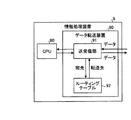
図12は、ルーティングテーブルを用いてデータの転送を行う情報処理装置を示す図である。図12に示すように、情報処理装置9は、情報処理を行うCPU(Central Processing Unit)80と、データを転送するデータ転送装置90を有する。
FIG. 12 is a diagram illustrating an information processing apparatus that transfers data using a routing table. As shown in FIG. 12, the information processing apparatus 9 includes a CPU (Central Processing Unit) 80 that performs information processing and a
データ転送装置90は、CPU80が送信するデータを受信し、受信したデータを他の情報処理装置へ送信する。また、データ転送装置90は、他の情報処理装置から送信されたデータを受信し、受信したデータをCPU80又は転送先の情報処理装置へ送信する。遠くに離れた情報処理装置間では、複数の情報処理装置によるデータ転送の繰り返しによりデータの送信が行われる。
The
データ転送装置90は、他の情報処理装置及びCPU80とデータの送受信を行う送受信部91とルーティングテーブル92とを有する。ルーティングテーブル92は、データの宛先とデータの転送先とを対応付けたマッピング情報を記憶し、データの宛先からデータの転送先を検索する検索テーブルである。送受信部91は、受信したデータの宛先からルーティングテーブル92を用いてデータの転送先を検索し、検索した転送先にデータを送信する。
The
なお、ルーティングテーブルに関しては、第1のテーブル及び第2のテーブルを独立して並行に検索する従来技術がある(例えば、特許文献1参照)。また、ルーティングテーブル中の一部のルーティングエントリをキャッシュ用ルーティングテーブルに記憶する。そして、キャッシュ用ルーティングテーブルを検索する第1の検索部とルーティングテーブルを検索する第2の検索部を備えるルータ装置が従来からある(例えば、特許文献2参照)。 As for the routing table, there is a conventional technique in which the first table and the second table are independently searched in parallel (see, for example, Patent Document 1). Also, some routing entries in the routing table are stored in the cache routing table. Conventionally, there is a router device including a first search unit that searches a routing table for cache and a second search unit that searches a routing table (see, for example, Patent Document 2).
また、ルーティングテーブルと、ルーティングエントリを用いてすでにルートが決定されたパケットの宛先アドレスとルートとの対応関係を表すキャッシュエントリが登録されるキャッシュテーブルとを備えるルータ装置が従来からある(例えば、特許文献3参照)。また、ネットワークアドレス変換表にパケットの宛先アドレスに対応する経路情報を記憶し、ネットワークアドレス変換表を検査して経路情報がない場合に経路表から経路情報を選出する従来技術がある(例えば、特許文献4参照)。 Conventionally, there is a router device including a routing table and a cache table in which a cache entry indicating a correspondence relationship between a destination address of a packet whose route has already been determined using the routing entry and the route is registered (for example, a patent) Reference 3). In addition, there is a conventional technique for storing route information corresponding to a destination address of a packet in a network address conversion table and selecting the route information from the route table when the network address conversion table is inspected and there is no route information (for example, patents) Reference 4).
ルーティングテーブルは数千個のエントリを有することから、ルーティングテーブルの検索に時間がかかるという問題がある。すなわち、ルーティングテーブルの検索ではルーティングテーブルのエントリ内の宛先と転送するパケットの宛先とを1エントリずつ比較するため、エントリの数が多いと検索処理に時間がかかる。 Since the routing table has several thousand entries, there is a problem that it takes time to search the routing table. That is, in the routing table search, the destination in the routing table entry is compared with the destination of the packet to be transferred one entry at a time. Therefore, if the number of entries is large, the search process takes time.
本発明は、1つの側面では、ルーティングテーブルの検索時間を短縮することを目的とする。 An object of one aspect of the present invention is to shorten a search time of a routing table.
本願の開示するデータ転送装置は、1つの態様において、第1の検索部と第2の検索部と転送部とを有する。第1の検索部は、データの宛先とルーティング先とを対応付けて記憶し、データの宛先からルーティング先を1エントリずつ検索する。また、第2の検索部は、データの宛先とルーティング先とを対応付けて第1の検索部より小さい記憶容量で記憶し、データの宛先からルーティング先を全エントリを対象として一度に第1の検索部と並行して検索する。また、転送部は、第2の検索部によりルーティング先が検索された場合には、該検索されたルーティング先にデータを転送し、第2の検索部によりルーティング先が検索されなかった場合には、第1の検索部により検索されたルーティング先にデータを転送する。 In one aspect, the data transfer device disclosed in the present application includes a first search unit, a second search unit, and a transfer unit. The first search unit stores the data destination and the routing destination in association with each other, and searches the routing destination from the data destination one entry at a time. The second search unit associates the data destination with the routing destination and stores the data with a smaller storage capacity than the first search unit, and sets the routing destination from the data destination to the first entry for all entries at once . Search in parallel with the search unit. Further, when the routing destination is searched by the second search unit, the transfer unit transfers the data to the searched routing destination, and when the routing destination is not searched by the second search unit. The data is transferred to the routing destination searched by the first search unit.
1実施態様によれば、ルーティングテーブルの検索時間を短縮することができる。 According to one embodiment, the routing table search time can be reduced.
以下に、本願の開示するデータ転送装置、情報処理装置及びデータ転送方法の実施例を図面に基づいて詳細に説明する。なお、この実施例は開示の技術を限定するものではない。 Hereinafter, embodiments of a data transfer device, an information processing device, and a data transfer method disclosed in the present application will be described in detail with reference to the drawings. Note that this embodiment does not limit the disclosed technology.
まず、実施例に係るノードの構成について説明する。図1は、実施例に係るノードの構成を示す図である。図1に示すように、ノード10は、CPU11と、メモリーコントローラ12と、メモリー13と、ストレージコントローラ14と、ストレージ15と、無線LAN(Local Area Network)コントローラ100とを有する情報処理装置である。また、ノード10は、管理部16と、インターコネクト17とを有する。
First, the configuration of the node according to the embodiment will be described. FIG. 1 is a diagram illustrating a configuration of a node according to the embodiment. As illustrated in FIG. 1, the
CPU11は、メモリー13に記憶されたプログラムを読み出して実行する中央処理装置である。メモリーコントローラ12は、メモリー13へのデータの書き込み、メモリー13からのプログラム及びデータの読み出しを制御する制御装置である。メモリー13は、プログラムやデータを記憶するRAM(Random Access Memory)である。
The
ストレージコントローラ14は、ストレージ15へのデータの書き込み、ストレージ15からのプログラム及びデータの読み出しを制御する制御装置である。ストレージ15は、プログラムやデータを記憶する磁気ディスク装置である。
The
無線LANコントローラ100は、無線LANを用いて他のノードと通信を行う装置である。無線LANコントローラ100は、ルーティングテーブルを用いてデータを他のノードへ転送するデータ転送装置である。
The
管理部16は、ノード10の監視や制御を行う。また、管理部16は、無線LANコントローラ100のルーティング情報を管理する。具体的には、管理部16は、後述する大容量ルーティングテーブル及び小容量ルーティングテーブルのルーティング情報を管理し、無線LANコントローラ100にルーティング情報の設定を指示する。
The management unit 16 performs monitoring and control of the
インターコネクト17は、ノード10、CPU11、メモリーコントローラ12、ストレージコントローラ14、無線LANコントローラ100及び管理部16を相互に接続する装置である。
The
次に、無線LANコントローラ100の構成について説明する。図2は、無線LANコントローラ100の構成を示す図である。図2に示すように、無線LANコントローラ100は、無線LAN送受信部110と、大容量ルーティングテーブル120と、小容量ルーティングテーブル130とを有する。
Next, the configuration of the
無線LAN送受信部110は、無線LANを用いて他のノードと無線LANフレームの送受信を行う。具体的には、無線LAN送受信部110は、インターコネクト17を介してCPU11から受信したデータを無線LANフレームにより他のノードへ送信する。また、無線LAN送受信部110は、他のノードから受信した無線LANフレームに含まれるデータをインターコネクト17を介してCPU11に送信する。また、無線LAN送受信部110は、他のノードから受信した無線LANフレームを別のノードに転送する。
The wireless LAN transmission /
図3は、無線LANフレームの転送の一例を示す図である。図3は、ノードA〜ノードPを有する情報処理システムにおいて、ノードAがノードOに無線LANフレームを送信する場合を示す。 FIG. 3 is a diagram illustrating an example of wireless LAN frame transfer. FIG. 3 shows a case where the node A transmits a wireless LAN frame to the node O in the information processing system having the nodes A to P.
ノードAは、宛先ノードOにネクストノードFを対応付けるマッピング情報を用いて無線LANフレームをノードFに送信する。ここで、ネクストノードとは、無線LANフレームを宛先ノードに到達させるために次に送信する送信先のノードを示す。 The node A transmits a wireless LAN frame to the node F using the mapping information that associates the next node F with the destination node O. Here, the next node indicates a destination node to be transmitted next in order to reach the destination node with the wireless LAN frame.
宛先ノードOの無線LANフレームを受信したノードFは、宛先ノードOにネクストノードKを対応付けるマッピング情報を用いて無線LANフレームをノードKに転送する。また、宛先ノードOの無線LANフレームを受信したノードKは、宛先ノードOにネクストノードOを対応付けるマッピング情報を用いて無線LANフレームをノードOに転送する。このように、各ノードがマッピング情報を用いて無線LANフレームを転送することにより、無線LANフレームが宛先のノードまで送信される。 The node F that has received the wireless LAN frame of the destination node O transfers the wireless LAN frame to the node K using mapping information that associates the next node K with the destination node O. Also, the node K that has received the wireless LAN frame of the destination node O transfers the wireless LAN frame to the node O using mapping information that associates the next node O with the destination node O. As described above, each node transfers the wireless LAN frame using the mapping information, so that the wireless LAN frame is transmitted to the destination node.
なお、図3は、近距離無線を用いて無線LANフレームを転送する場合を示したが、情報処理システムに含まれるいくつかのノードは近距離無線に加えて遠距離無線で通信する機能を有し、遠距離無線を用いて無線LANフレームを転送することもできる。 Note that FIG. 3 shows a case in which a wireless LAN frame is transferred using short-range wireless communication. However, some nodes included in the information processing system have a function of communicating by long-range wireless communication in addition to short-range wireless communication. However, wireless LAN frames can also be transferred using long-distance radio.
近距離無線は高速かつ近距離ノード間の無線通信であり、遠距離無線は低速かつ遠距離ノード間の無線通信である。距離の離れた宛先ノードへ無線通信を行うには、送信元ノードは、遠距離無線で通信する機能を有するノードへ近距離無線で送信する。そして、遠距離無線で通信する機能を有するノードが、宛先ノードの近くの遠距離無線で通信する機能を有するノードへ遠距離無線で転送を行う。そして、宛先ノードの近くの遠距離無線で通信する機能を有するノードが、近距離無線で宛先ノードへの転送を行う。 Short-range wireless is high-speed wireless communication between short-distance nodes, and long-distance wireless is low-speed wireless communication between long-distance nodes. In order to perform wireless communication with a remote destination node, a transmission source node transmits to a node having a function of performing communication with a long-distance wireless by a short-range wireless. Then, the node having the function of communicating by the long-distance radio performs transfer by the long-distance radio to the node having the function of communicating by the long-distance radio near the destination node. Then, a node having a function of communicating with a long-distance wireless near the destination node performs transfer to the destination node with a short-range wireless.
なお、図3では、説明の便宜上ノードA〜ノードPまで16個のノードを有する情報処理システムを示したが、情報処理システムは、例えば、数千個などより多くの数のノードを有することができる。 3 shows an information processing system having 16 nodes from node A to node P for convenience of explanation, the information processing system may have a larger number of nodes, for example, thousands. it can.
図4は、無線LANフレームの一例を示す図である。図4に示すように、無線LANフレームは、ヘッダ部に送信元MAC(Media Access Control)アドレスと宛先MACアドレスとネクストノードMACアドレスを有する。無線LANフレームを受信したノードは、ネクストノードMACアドレスが自身のMACアドレスと等しい無線LANフレーム以外は廃棄する。 FIG. 4 is a diagram illustrating an example of a wireless LAN frame. As shown in FIG. 4, the wireless LAN frame has a source MAC (Media Access Control) address, a destination MAC address, and a next node MAC address in a header portion. The node that has received the wireless LAN frame discards other than the wireless LAN frame whose next node MAC address is equal to its own MAC address.
このように、各ノードが、受信した無線LANフレームのうち、ネクストノードMACアドレスが自身のMACアドレスと等しい無線LANフレーム以外を廃棄することにより、無線LANフレームはネクストノードだけに送信される。 As described above, each node discards the received wireless LAN frame other than the wireless LAN frame whose next node MAC address is equal to its own MAC address, so that the wireless LAN frame is transmitted only to the next node.
図2に戻って、無線LAN送受信部110は、制御部111を有する。制御部111は、大容量ルーティングテーブル120及び小容量ルーティングテーブル130を用いてデータの宛先から無線LANフレームの送信先のノードを決定する。
Returning to FIG. 2, the wireless LAN transmission /
また、制御部111は、大容量ルーティングテーブル120と小容量ルーティングテーブル130に同時に検索指示を出す。ここで、「同時に」とは、「ほぼ同時に」を意味し、無線LAN送受信部110は、全く同じタイミングで検索指示を出す必要はない。
Further, the
また、制御部111は、管理部16の指示に基づいて、大容量ルーティングテーブル120及び小容量ルーティングテーブル130へのマッピング情報の書き込みを制御する。
Further, the
大容量ルーティングテーブル120は、全ての宛先ノードに対するマッピング情報を記憶する大容量のルーティングテーブルである。大容量ルーティングテーブル120は、一度に1個のエントリだけを参照することができる。大容量ルーティングテーブル120は、例えば、SRAM又はDRAMで構成される。 The large-capacity routing table 120 is a large-capacity routing table that stores mapping information for all destination nodes. The large capacity routing table 120 can refer to only one entry at a time. The large capacity routing table 120 is constituted by, for example, SRAM or DRAM.
図5は、SRAMで構成される大容量ルーティングテーブル120の一例を示す図である。図5に示すように、大容量ルーティングテーブル120は、4096個のエントリを有するエントリ部121と、制御部122とを有する。各エントリは、宛先ノードMACアドレスにネクストノードMACアドレスを対応付けている。
FIG. 5 is a diagram showing an example of the large-capacity routing table 120 composed of SRAM. As shown in FIG. 5, the large-capacity routing table 120 includes an entry unit 121 having 4096 entries and a
制御部122は、無線LAN送受信部110から宛先ノードのMACアドレスxを受け取り、エントリ部121のエントリを1つずつ参照して、受け取ったMACアドレスxと宛先ノードMACアドレスとを比較する。そして、制御部122は、受け取ったMACアドレスxと一致する宛先ノードMACアドレスを見つけると、宛先ノードMACアドレスxに対応付けられたネクストノードのMACアドレスyを無線LAN送受信部110に渡す。
The
小容量ルーティングテーブル130は、マッピング情報の一部を記憶する小容量のルーティングテーブルである。小容量ルーティングテーブル130は、一度に全エントリを参照することができ、大容量ルーティングテーブル120と比較して高速にネクストノードのMACアドレスを検索する。小容量ルーティングテーブル130は、例えば、フリップフロップ(FF)で構成される。 The small capacity routing table 130 is a small capacity routing table that stores a part of the mapping information. The small capacity routing table 130 can refer to all entries at once, and searches for the MAC address of the next node at a higher speed than the large capacity routing table 120. The small capacity routing table 130 is composed of, for example, a flip-flop (FF).
図6は、FFで構成される小容量ルーティングテーブル130の一例を示す図である。図6に示すように、小容量ルーティングテーブル130は、32個のエントリを有するエントリ部131と、制御部132とを有する。各エントリは、宛先ノードMACアドレスにネクストノードMACアドレスを対応付けている。
FIG. 6 is a diagram illustrating an example of the small-capacity routing table 130 configured by FFs. As shown in FIG. 6, the small-capacity routing table 130 includes an
制御部132は、無線LAN送受信部110から宛先ノードのMACアドレスxを受け取り、エントリ部131の全エントリを一度に参照して、受け取ったMACアドレスxと各宛先ノードMACアドレスとを一度に比較する。そして、制御部132は、受け取ったMACアドレスxと一致する宛先ノードMACアドレスを見つけると、宛先ノードのMACアドレスxに対応付けられたネクストノードのMACアドレスyを無線LAN送受信部110に渡す。
The
小容量ルーティングテーブル130は、動作クロックの周波数の1サイクル程度で宛先ノードMACアドレス一致処理などを処理できる範囲内のエントリ数を有する。また、小容量ルーティングテーブル130は、近距離無線通信で通信可能なノードを宛先ノードとするマッピング情報を記憶する。 The small-capacity routing table 130 has the number of entries within a range in which the destination node MAC address matching process can be processed in about one cycle of the frequency of the operation clock. The small-capacity routing table 130 stores mapping information in which a node that can communicate by near field communication is a destination node.
例えば、近距離無線通信により、上下方向にそれぞれ2ノードまで、左右方向にそれぞれ2ノードまでの範囲で通信可能である場合には、図7に示すように、5×5=25のノードのうち自身を除いた24が近距離無線で通信可能なノード数である。したがって、動作クロックの周波数においては64エントリ程度まで1サイクルでアドレス一致などの処理をできる場合には、小容量ルーティングテーブル130のエントリ数は、24以上で64以下の数として32とすることができる。 For example, when short-range wireless communication is possible within a range of up to 2 nodes in the vertical direction and 2 nodes in the horizontal direction, as shown in FIG. 24 excluding itself is the number of nodes that can communicate by short-range wireless communication. Accordingly, when address matching or the like can be performed in one cycle up to about 64 entries at the frequency of the operation clock, the number of entries in the small capacity routing table 130 can be 32 as a number of 24 or more and 64 or less. .
また、情報処理システムが筐体内に1000個のノードを格納できる場合には、大容量ルーティングテーブル120のエントリ数を1024とすることができる。 When the information processing system can store 1000 nodes in the housing, the number of entries in the large-capacity routing table 120 can be set to 1024.
なお、大容量ルーティングテーブル120が記憶するマッピング情報は、情報処理システム全体を管理する管理装置が作成し、各ノードの管理部16が管理する。また、各ノードの管理部16は、マッピング情報の大容量ルーティングテーブル120への設定を無線LANコントローラ100に指示する。
Note that the mapping information stored in the large-capacity routing table 120 is created by a management apparatus that manages the entire information processing system, and is managed by the management unit 16 of each node. Further, the management unit 16 of each node instructs the
また、小容量ルーティングテーブル130が記憶するマッピング情報は、各ノードの管理部16が大容量ルーティングテーブル120から近距離無線の通信範囲を抽出して小容量ルーティングテーブル130への設定を無線LANコントローラ100に指示する。管理部16は、大容量ルーティングテーブル120のエントリのうち、宛先ノードMACアドレスとネクストノードMACアドレスが等しいエントリを近距離無線の通信範囲として抽出する。
The mapping information stored in the small-capacity routing table 130 is that the management unit 16 of each node extracts the short-range wireless communication range from the large-capacity routing table 120 and sets the small-capacity routing table 130 in the
次に、実施例に係る無線LANコントローラ100によるルーティング処理のフローについて説明する。図8は、実施例に係る無線LANコントローラ100によるルーティング処理のフローを示すフローチャートである。
Next, a flow of routing processing by the
図8に示すように、無線LANコントローラ100は、小容量ルーティングテーブル130及び大容量ルーティングテーブル120で同時に検索を開始する(ステップS1)。
As shown in FIG. 8, the
そして、無線LANコントローラ100は、小容量ルーティングテーブル130で宛先ノードのMACアドレスが発見されたか否かを判定する(ステップS2)。そして、小容量ルーティングテーブル130で宛先ノードのMACアドレスが発見されなかった場合には、無線LANコントローラ100は、大容量ルーティングテーブル120で宛先ノードのMACアドレスが発見されたか否かを判定する(ステップS3)。
Then, the
そして、大容量ルーティングテーブル120で宛先ノードのMACアドレスが発見されなかった場合は、無線LANコントローラ100は、ルーティングテーブルに宛先ノードのMACアドレスが見つからなかったので、異常ケースとして処理する(ステップS4)。
If the MAC address of the destination node is not found in the large-capacity routing table 120, the
一方、大容量ルーティングテーブル120で宛先ノードのMACアドレスが発見された場合は、無線LANコントローラ100は、発見したエントリ内のマッピング情報からネクストノードのMACアドレスを取得する(ステップS5)。そして、無線LANコントローラ100は、フレームをネクストノードに送信する(ステップS6)。
On the other hand, when the MAC address of the destination node is found in the large capacity routing table 120, the
また、小容量ルーティングテーブル130で宛先ノードのMACアドレスが発見された場合には、無線LANコントローラ100は、大容量ルーティングテーブル120の検索をキャンセルし(ステップS7)、ステップS5に移動する。
When the MAC address of the destination node is found in the small capacity routing table 130, the
このように、小容量ルーティングテーブル130及び大容量ルーティングテーブル120で同時に検索を開始することによって、無線LANコントローラ100は、ルーティング先を高速に検索することができる。
In this way, by simultaneously starting a search in the small capacity routing table 130 and the large capacity routing table 120, the
次に、管理部16による小容量ルーティングテーブル130のマッピング情報作成処理のフローについて説明する。図9は、管理部16による小容量ルーティングテーブル130のマッピング情報作成処理のフローを示すフローチャートである。 Next, the flow of the mapping information creation process of the small capacity routing table 130 by the management unit 16 will be described. FIG. 9 is a flowchart showing a flow of the mapping information creation process of the small capacity routing table 130 by the management unit 16.
図9に示すように、管理部16は、大容量ルーティングテーブル120のマッピング情報を検索することにより、宛先ノードが近距離無線の通信範囲に含まれるマッピング情報を抽出する(ステップS11)。 As illustrated in FIG. 9, the management unit 16 searches the mapping information in the large-capacity routing table 120 to extract the mapping information in which the destination node is included in the short-range wireless communication range (step S11).
具体的には、管理部16は、大容量ルーティングテーブル120のマッピング情報のうち、宛先ノードとネクストノードでMACアドレスが等しいエントリの情報を、宛先ノードが近距離無線の通信範囲に含まれるマッピング情報として抽出する。 Specifically, the management unit 16 includes information on entries having the same MAC address between the destination node and the next node in the mapping information of the large-capacity routing table 120, and mapping information in which the destination node is included in the communication range of the short-range wireless communication. Extract as
そして、管理部16は、抽出したマッピング情報を小容量ルーティングテーブル130に設定するように無線LANコントローラ100に指示する(ステップS12)。
Then, the management unit 16 instructs the
このように、管理部16は、大容量ルーティングテーブル120のマッピング情報のうち、宛先ノードとネクストノードでMACアドレスが等しいエントリの情報を小容量ルーティングテーブル130のマッピング情報とする。したがって、無線LANコントローラ100は、自動で小容量ルーティングテーブル130を設定することができる。
As described above, the management unit 16 sets the information of the entry having the same MAC address between the destination node and the next node in the mapping information of the large capacity routing table 120 as the mapping information of the small capacity routing table 130. Therefore, the
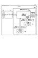
次に、大容量ルーティングテーブル120に加えて小容量ルーティングテーブル130を備える効果について説明する。図10は、大容量ルーティングテーブル120に加えて小容量ルーティングテーブル130を備える効果を説明するための図である。 Next, the effect of including the small capacity routing table 130 in addition to the large capacity routing table 120 will be described. FIG. 10 is a diagram for explaining the effect of including the small capacity routing table 130 in addition to the large capacity routing table 120.
図10(a)は、大容量ルーティングテーブル120だけをルーティングテーブルとして用いる場合を示し、図10(b)は、大容量ルーティングテーブル120に加えて小容量ルーティングテーブル130を用いる場合を示す。 FIG. 10A shows a case where only the large-capacity routing table 120 is used as the routing table, and FIG. 10B shows a case where the small-capacity routing table 130 is used in addition to the large-capacity routing table 120.
図10(a)に示すように、送信ノードのCPUが無線LANコントローラにデータ送信を要求すると、無線LANコントローラはルーティングテーブルを用いてルーティング先を検索する。ここで、ルーティングテーブルは、一度に1エントリしか参照できないため、宛先ノードを見つけるまでに何度もエントリを参照する。 As shown in FIG. 10A, when the CPU of the transmission node requests the wireless LAN controller to transmit data, the wireless LAN controller searches for a routing destination using the routing table. Here, since the routing table can refer to only one entry at a time, the entry is referred to many times until a destination node is found.
一方、図10(b)に示すように、送信ノードのCPU11が無線LANコントローラ100にデータ送信を要求すると、無線LANコントローラ100は小容量ルーティングテーブル130と大容量ルーティングテーブル120を用いてルーティング先を検索する。
On the other hand, as illustrated in FIG. 10B, when the
ここで、小容量ルーティングテーブル130は、一度に全エントリを参照するので、小容量ルーティングテーブル130に宛先ノードが登録されている場合には、エントリの参照は1回ですむ。したがって、無線LANコントローラ100はルーティング先を検索することによるレイテンシーを短縮することができる。
Here, since the small-capacity routing table 130 refers to all entries at once, if the destination node is registered in the small-capacity routing table 130, it is only necessary to refer to the entry once. Therefore, the
なお、管理部16の機能はファームウェアにより実現される。そこで、ファームウェアにより実現される管理部16のハードウェア構成について説明する。図11は、管理部16のハードウェア構成を示す図である。図11に示すように、管理部16は、MPU161と、フラッシュメモリー162と、RAM163とを有する。
The function of the management unit 16 is realized by firmware. Therefore, a hardware configuration of the management unit 16 realized by firmware will be described. FIG. 11 is a diagram illustrating a hardware configuration of the management unit 16. As illustrated in FIG. 11, the management unit 16 includes an MPU 161, a
MPU161は、フラッシュメモリー162からプログラムを読み出して実行する演算処理装置である。フラッシュメモリー162は、プログラムを記憶する不揮発性メモリーである。RAM163は、プログラムの途中結果などを記憶するメモリーである。
The MPU 161 is an arithmetic processing unit that reads and executes a program from the
上述してきたように、実施例では、無線LANコントローラ100は、一度に1エントリだけを参照する大容量ルーティングテーブル120と一度に全エントリを参照する小容量ルーティングテーブル130を備える。そして、無線LANコントローラ100は、両方のルーティングテーブルを同時に検索し、小容量ルーティングテーブル130に宛先ノードが登録されている場合には、一度の検索でネクストノードのMACアドレスを取得する。したがって、無線LANコントローラ100は、大容量ルーティングテーブル120だけを備える場合と比較して、高速にルーティング先を検索することができる。
As described above, in the embodiment, the
また、実施例では、近距離無線で通信可能な範囲のノードを宛先ノードとして小容量ルーティングテーブル130がマッピング情報を記憶する。したがって、ノード10は、近距離無線で通信可能な範囲のノードについては、他のノードと比較して高速にルーティング先を検索することができる。
In the embodiment, the small-capacity routing table 130 stores mapping information with a node in a range that can be communicated by short-range wireless as a destination node. Therefore, the
また、実施例では、管理部16が、大容量ルーティングテーブル120のマッピング情報のうち、宛先ノードとネクストノードでMACアドレスが等しいエントリの情報を小容量ルーティングテーブル130のマッピング情報とする。したがって、無線LANコントローラ100は、自動で小容量ルーティングテーブル130を設定することができる。
In the embodiment, the management unit 16 uses the mapping information of the large-capacity routing table 120 as the mapping information of the small-capacity routing table 130 in the mapping information of the large-capacity routing table 120. Therefore, the
なお、実施例では、無線で通信する場合について説明したが、本発明はこれに限定されるものではなく、有線で通信する場合にも同様に適用することができる。その場合、小容量ルーティングテーブル130は、近距離無線で通信可能な宛先の代わりに、一定の距離範囲内のノードを宛先とするルーティング情報を記憶する。 In the embodiment, the case where communication is performed wirelessly has been described. However, the present invention is not limited to this, and can be similarly applied to the case where communication is performed via wire. In this case, the small-capacity routing table 130 stores routing information destined for a node within a certain distance range, instead of a destination capable of communication by short-range wireless communication.
また、実施例では、大容量ルーティングテーブル120及び小容量ルーティングテーブル130を用いる場合について説明した。しかしながら、本発明はこれに限定されるものではなく、容量が順に小さくなる一方で検索が高速になるn個のルーティングテーブルを用いる場合にも同様に適用することができる。 In the embodiment, the case where the large-capacity routing table 120 and the small-capacity routing table 130 are used has been described. However, the present invention is not limited to this, and can be similarly applied to a case where n routing tables are used in which the capacity decreases in order while the search speed is high.
また、実施例では、小容量ルーティングテーブル130が、近距離無線通信で通信可能なノードを宛先ノードとするマッピング情報を記憶する場合について説明した。しかしながら、本発明はこれに限定されるものではなく、LRU(Least Recently Used)アルゴリズムを用いて、使用頻度の多い宛先ノードを小容量ルーティングテーブルに登録する場合にも同様に適用することができる。すなわち、使用頻度の少ない(無い)宛先ノードを小容量ルーティングテーブルから追い出す方法で小容量ルーティングテーブルの登録や入れ替えを行うこともできる。 In the embodiment, a case has been described in which the small-capacity routing table 130 stores mapping information whose destination node is a node that can communicate with short-range wireless communication. However, the present invention is not limited to this, and the present invention can be similarly applied to a case where destination nodes that are frequently used are registered in the small-capacity routing table using an LRU (Least Recently Used) algorithm. In other words, the small capacity routing table can be registered or replaced by a method of expelling a destination node that is not frequently used (not present) from the small capacity routing table.
また、実施例では、管理部16が小容量ルーティングテーブル130のマッピング情報を作成する場合について説明した。しかしながら、本発明はこれに限定されるものではなく、例えば、CPU11で動作するOSなどが小容量ルーティングテーブル130のマッピング情報を作成する場合にも同様に適用することができる。
In the embodiment, the case where the management unit 16 creates the mapping information of the small capacity routing table 130 has been described. However, the present invention is not limited to this. For example, the present invention can be similarly applied to a case where the OS operating on the
また、実施例では、管理部16は、大容量ルーティングテーブル120のマッピング情報から小容量ルーティングテーブル130のマッピング情報を抽出する場合について説明した。しかしながら、本発明はこれに限定されるものではなく、管理部16が、筐体内の各ノードの位置及び近距離無線の通信範囲に基づいて小容量ルーティングテーブル130のマッピング情報を作成する場合にも同様に適用することができる。 In the embodiment, the case where the management unit 16 extracts the mapping information of the small capacity routing table 130 from the mapping information of the large capacity routing table 120 has been described. However, the present invention is not limited to this, and the management unit 16 also creates mapping information of the small capacity routing table 130 based on the position of each node in the housing and the communication range of the short-range wireless communication. The same can be applied.
また、実施例では、大容量ルーティングテーブル120及び小容量ルーティングテーブル130の宛先ノードを識別する識別子としてMACアドレスを用いる場合について説明した。しかしながら、本発明はこれに限定されるものではなく、宛先ノードを識別する識別子として他の識別子を用いる場合にも同様に適用することができる。 In the embodiment, the case where the MAC address is used as an identifier for identifying the destination node of the large capacity routing table 120 and the small capacity routing table 130 has been described. However, the present invention is not limited to this, and can be similarly applied to the case where another identifier is used as an identifier for identifying the destination node.
9 情報処理装置
10 ノード
11,80 CPU
12 メモリーコントローラ
13 メモリー
14 ストレージコントローラ
15 ストレージ
16 管理部
17 インターコネクト
90 データ転送装置
91 送受信部
92 ルーティングテーブル
100 無線LANコントローラ
110 無線LAN送受信部
111 制御部
120 大容量ルーティングテーブル
121 エントリ部
122 制御部
130 小容量ルーティングテーブル
131 エントリ部
132 制御部
161 MPU
162 フラッシュメモリー
163 RAM9
DESCRIPTION OF
162
Claims (5)
データの宛先とルーティング先とを対応付けて前記第1の検索部より小さい記憶容量で記憶し、データの宛先からルーティング先を全エントリを対象として一度に前記第1の検索部と並行して検索する第2の検索部と、
前記第2の検索部によりルーティング先が検索された場合には、該検索されたルーティング先にデータを転送し、前記第2の検索部によりルーティング先が検索されなかった場合には、前記第1の検索部により検索されたルーティング先にデータを転送する転送部と
を有することを特徴とするデータ転送装置。 A first search unit for storing a destination of data and a routing destination in association with each other, and searching for a routing destination from the data destination one by one;
The data destination and the routing destination are associated with each other and stored in a smaller storage capacity than the first search unit, and the routing destination is searched from the data destination for all entries in parallel with the first search unit at a time . A second search unit to
When a routing destination is searched by the second search unit, data is transferred to the searched routing destination, and when a routing destination is not searched by the second search unit, the first A data transfer apparatus comprising: a transfer unit that transfers data to a routing destination searched by the search unit.
前記第2の検索部は、前記第2の無線で通信可能な宛先についてのルーティング先を記憶することを特徴とする請求項1に記載のデータ転送装置。 The transfer unit transfers data using a first radio or a second radio having a shorter communication distance than the first radio,
The second search unit, a data transfer apparatus according to claim 1, characterized in that storing a routing destination for communicable destination in the second radio.
前記データ転送装置は、
データの宛先とルーティング先とを対応付けて記憶し、データの宛先からルーティング先を1エントリずつ検索する第1の検索部と、
データの宛先とルーティング先とを対応付けて前記第1の検索部より小さい記憶容量で記憶し、データの宛先からルーティング先を全エントリを対象として一度に前記第1の検索部と並行して検索する第2の検索部と、
前記第2の検索部によりルーティング先が検索された場合には、該検索されたルーティング先にデータを転送し、前記第2の検索部によりルーティング先が検索されなかった場合には、前記第1の検索部により検索されたルーティング先にデータを転送する転送部と
を有することを特徴とする情報処理装置。 In an information processing apparatus that performs information processing while performing communication using a data transfer apparatus,
The data transfer device
A first search unit for storing a destination of data and a routing destination in association with each other, and searching for a routing destination from the data destination one by one;
The data destination and the routing destination are associated with each other and stored in a smaller storage capacity than the first search unit, and the routing destination is searched from the data destination for all entries in parallel with the first search unit at a time . A second search unit to
When a routing destination is searched by the second search unit, data is transferred to the searched routing destination, and when a routing destination is not searched by the second search unit, the first And a transfer unit for transferring data to the routing destination searched by the search unit.
データの宛先とルーティング先とを対応付けて第1の記憶部に記憶し、該第1の記憶部を用いてデータの宛先からルーティング先を1エントリずつ検索し、
データの宛先とルーティング先とを対応付けて前記第1の記憶部より記憶容量が小さい第2の記憶部に記憶し、該第2の記憶部を用いてデータの宛先からルーティング先を全エントリを対象として一度に前記第1の記憶部を用いる検索と並行して検索し、
前記第2の記憶部からルーティング先が検索された場合には、該検索されたルーティング先にデータを転送し、前記第2の記憶部からルーティング先が検索されなかった場合には、前記第1の記憶部から検索されたルーティング先にデータを転送する
ことを特徴とするデータ転送方法。 In a data transfer method by a data transfer device for transferring data,
The data destination and the routing destination are associated and stored in the first storage unit, and the routing destination is retrieved from the data destination one entry at a time using the first storage unit,
Data destinations and routing destinations are associated with each other and stored in a second storage unit having a storage capacity smaller than that of the first storage unit, and all entries of routing destinations from the data destinations are stored using the second storage unit. Search in parallel with the search using the first storage unit at a time as a target,
When a routing destination is retrieved from the second storage unit, data is transferred to the retrieved routing destination, and when a routing destination is not retrieved from the second storage unit, the first A data transfer method comprising transferring data from a storage unit to a routing destination searched for.
Applications Claiming Priority (1)
| Application Number | Priority Date | Filing Date | Title |
|---|---|---|---|
| PCT/JP2013/077671 WO2015052818A1 (en) | 2013-10-10 | 2013-10-10 | Data forwarding device, information processing device, and data forwarding method |
Publications (2)
| Publication Number | Publication Date |
|---|---|
| JPWO2015052818A1 JPWO2015052818A1 (en) | 2017-03-09 |
| JP6098728B2 true JP6098728B2 (en) | 2017-03-22 |
Family
ID=52812665
Family Applications (1)
| Application Number | Title | Priority Date | Filing Date |
|---|---|---|---|
| JP2015541387A Active JP6098728B2 (en) | 2013-10-10 | 2013-10-10 | Data transfer apparatus, information processing apparatus, and data transfer method |
Country Status (2)
| Country | Link |
|---|---|
| JP (1) | JP6098728B2 (en) |
| WO (1) | WO2015052818A1 (en) |
Family Cites Families (4)
| Publication number | Priority date | Publication date | Assignee | Title |
|---|---|---|---|---|
| JPH1056474A (en) * | 1996-08-08 | 1998-02-24 | Hitachi Ltd | Multilayer switch |
| JP2000083055A (en) * | 1998-09-04 | 2000-03-21 | Hitachi Ltd | Router |
| JP2006135660A (en) * | 2004-11-05 | 2006-05-25 | Alaxala Networks Corp | Association memory and packet transfer device |
| US8243733B2 (en) * | 2008-06-19 | 2012-08-14 | Marvell World Trade Ltd. | Cascaded memory tables for searching |
-
2013
- 2013-10-10 JP JP2015541387A patent/JP6098728B2/en active Active
- 2013-10-10 WO PCT/JP2013/077671 patent/WO2015052818A1/en active Application Filing
Also Published As
| Publication number | Publication date |
|---|---|
| JPWO2015052818A1 (en) | 2017-03-09 |
| WO2015052818A1 (en) | 2015-04-16 |
Similar Documents
| Publication | Publication Date | Title |
|---|---|---|
| KR102162730B1 (en) | Technologies for distributed routing table lookup | |
| JP6581277B2 (en) | Data packet transfer | |
| KR102437780B1 (en) | System for prediting solid state drive memory cache occupancy and method thereof | |
| JP6989621B2 (en) | Packet transmission methods, edge devices and machine-readable storage media | |
| JP7053798B2 (en) | Packet transfer method and equipment | |
| TWI661698B (en) | Method and device for forwarding Ethernet packet | |
| KR101476940B1 (en) | Switch system, and data forwarding method | |
| CN108173691B (en) | Cross-device aggregation method and device | |
| US9379979B2 (en) | Method and apparatus for establishing a virtual interface for a set of mutual-listener devices | |
| JP6928076B2 (en) | Packet monitoring | |
| JP6195014B2 (en) | COMMUNICATION SYSTEM, COMMUNICATION METHOD, RELAY DEVICE, AND COMMUNICATION PROGRAM | |
| US9979643B2 (en) | Communication apparatus, communication method, and computer-readable recording medium | |
| US20150188815A1 (en) | Packet Forwarding Method and System | |
| US20140226665A1 (en) | Communication apparatus, control method therefor, and computer-readable storage medium | |
| CN104821916A (en) | Reducing the size of IPv6 routing tables by using bypass tunnels | |
| CN104363084A (en) | Link status synchronization method and device | |
| CN107977160B (en) | Method for data access of exchanger | |
| US20140198770A1 (en) | Node device, communication method, and storage medium | |
| JP6098728B2 (en) | Data transfer apparatus, information processing apparatus, and data transfer method | |
| JP2012235400A5 (en) | ||
| KR101952187B1 (en) | Method and apparatus for processing service node ability, service classifier and service controller | |
| WO2017028806A1 (en) | Message forwarding method and device | |
| JP6470640B2 (en) | COMMUNICATION DEVICE, ITS CONTROL METHOD, COMPUTER PROGRAM | |
| JP2019536382A (en) | Packet forwarding | |
| CN109995678A (en) | Message transmitting method and device |
Legal Events
| Date | Code | Title | Description |
|---|---|---|---|
| A131 | Notification of reasons for refusal |
Free format text: JAPANESE INTERMEDIATE CODE: A131 Effective date: 20161018 |
|
| A521 | Written amendment |
Free format text: JAPANESE INTERMEDIATE CODE: A523 Effective date: 20161208 |
|
| TRDD | Decision of grant or rejection written | ||
| A01 | Written decision to grant a patent or to grant a registration (utility model) |
Free format text: JAPANESE INTERMEDIATE CODE: A01 Effective date: 20170124 |
|
| A61 | First payment of annual fees (during grant procedure) |
Free format text: JAPANESE INTERMEDIATE CODE: A61 Effective date: 20170206 |
|
| R150 | Certificate of patent or registration of utility model |
Ref document number: 6098728 Country of ref document: JP Free format text: JAPANESE INTERMEDIATE CODE: R150 |