JP6097670B2 - Display input device - Google Patents
Display input device Download PDFInfo
- Publication number
- JP6097670B2 JP6097670B2 JP2013221395A JP2013221395A JP6097670B2 JP 6097670 B2 JP6097670 B2 JP 6097670B2 JP 2013221395 A JP2013221395 A JP 2013221395A JP 2013221395 A JP2013221395 A JP 2013221395A JP 6097670 B2 JP6097670 B2 JP 6097670B2
- Authority
- JP
- Japan
- Prior art keywords
- display
- detection
- input device
- finger
- electrostatic sensor
- Prior art date
- Legal status (The legal status is an assumption and is not a legal conclusion. Google has not performed a legal analysis and makes no representation as to the accuracy of the status listed.)
- Active
Links
Images


Landscapes
- User Interface Of Digital Computer (AREA)
- Position Input By Displaying (AREA)
Description
本発明は、静電パネルで検知される接触検知位置と空間検知位置との差を利用して操作体の移動方向を検知できるようにした表示入力装置に関する。 The present invention relates to a display input device that can detect a moving direction of an operating body using a difference between a contact detection position detected by an electrostatic panel and a space detection position.
液晶表示装置などの表示画面の前方に静電センサを備えた表示入力装置は、表示画面と静電センサの操作面との間に距離があるため、表示画面を斜め前方から見たときの視差により、指などの操作体で操作面を触れたときの接触検知位置と、表示画面に表示されているボタン表示などの操作目標表示との間に操作誤差が発生する。 Since a display input device having an electrostatic sensor in front of a display screen such as a liquid crystal display device has a distance between the display screen and the operation surface of the electrostatic sensor, the parallax when the display screen is viewed obliquely from the front Accordingly, an operation error occurs between the contact detection position when the operation surface such as a finger touches the operation surface and the operation target display such as the button display displayed on the display screen.
この操作誤差により、目標のボタン表示に操作体を接触させたつもりでも、そのボタン表示が操作されていると検知されず、むしろその隣のボタン表示が操作されたものと誤って検知されることがある。 Due to this operational error, even if you intend to bring the operating body into contact with the target button display, it is not detected that the button display is being operated, but rather it is erroneously detected that the button display next to it is operated. There is.
以下の特許文献1には、操作者の視差に基づく前記操作誤差について記載されている。特許文献1に記載された入力装置は、ディスプレイの前方に複数の発光部と受光部とを備えた三次元入力装置が設けられている。この三次元入力装置で、ディスプレイから離れた位置でのホバー検知と、ディスプレイに接触したときのタッチ検知が可能となっている。 The following Patent Document 1 describes the operation error based on an operator's parallax. The input device described in Patent Document 1 is provided with a three-dimensional input device including a plurality of light emitting units and light receiving units in front of a display. With this three-dimensional input device, hover detection at a position away from the display and touch detection when touching the display are possible.
操作者の視差に基づく前記操作誤差については、ホバー検知のときに、表示画面に表示されるアイコンを大きくすることで対応している。 The operation error based on the parallax of the operator is dealt with by increasing the icon displayed on the display screen at the time of hover detection.
さらに、ホバー検知からタッチ検知に至るまでの時間を監視し、その時間が短いときはタッチされた場所にあるアイコンが操作されたものと判定され、前記時間が長いときはホバー検知で選択されたアイコンが操作されたものであると判定される。 Furthermore, the time from the hover detection to the touch detection is monitored, and when the time is short, it is determined that the icon at the touched place is operated, and when the time is long, the hover detection is selected. It is determined that the icon has been operated.
特許文献1に記載されているように、操作者の視差による操作誤差の対策としてアイコンを大きく表示させるものでは、大きく表示されたアイコンが表示画面の他の表示領域を狭めることになって、このアイコンをナビゲーション画面やテレビ画面などと併用するのは難しい。また、表示形態も複雑になり表示駆動回路の負担も大きくなる。 As described in Patent Document 1, in a case where an icon is displayed in a large size as a countermeasure for an operation error due to an operator's parallax, the icon displayed in a large size narrows the other display area of the display screen. It is difficult to use icons with navigation screens and TV screens. In addition, the display form becomes complicated and the burden on the display drive circuit increases.
また、特許文献1に記載された発明では、ホバー検知からタッチ検知に至るまでの時間を監視してはいるが、指がどの方向から操作されているのかを検知することができないため、操作性を向上させるのに限界があった。 In the invention described in Patent Document 1, although the time from hover detection to touch detection is monitored, it is impossible to detect from which direction the finger is operated. There was a limit to improving
本発明は上記従来の課題を解決するものであり、静電パネルの接触検知位置と空間検知位置との検知ずれを利用して、操作体の移動方向や移動距離などを検知できるようにした表示入力装置を提供することを目的としている。 The present invention solves the above-described conventional problems, and uses a detection deviation between the contact detection position and the space detection position of the electrostatic panel to detect the moving direction and the moving distance of the operating tool. An object is to provide an input device.
本発明は、表示画面と、前記表示画面の前方に位置する操作面と、前記操作面に接近しまたは接触した前記操作体を検出する静電センサと、前記静電センサの検知信号を処理する制御部と、が設けられている表示入力装置において、
前記制御部では、
(a)前記静電センサからの検出出力に基づいて、前記操作面から所定の距離だけ離れた第1の検知位置と、それよりも前記操作面に近い位置または前記操作面に触れる位置である第2の検知位置の少なくとも2箇所の検知位置のそれぞれに前記操作体が至ったことが認識されるとともに、
(b)前記静電センサで設定される座標上での前記操作体の検出位置である検出座標が求められて、
(c)前記第1の検知位置で得られた前記検出座標と前記第2の検知位置で得られた前記検出座標とから、操作体が前記操作面に接近する移動方向が算出され、
(d)前記移動方向の算出値に基づいて、操作を行おうとする前記操作体の前記検出座標と、前記移動方向の延長上で前記表示画面に表示されている操作目標表示との操作誤差距離が求められ、
(e)前記操作誤差距離に基づいて、前記静電センサからの検出出力に対する補正動作が行われる
ことを特徴とするものである。
The present invention processes a display screen, an operation surface positioned in front of the display screen, an electrostatic sensor that detects the operation body approaching or in contact with the operation surface, and a detection signal of the electrostatic sensor. In a display input device provided with a control unit,
In the control unit,
(A) based on the detection output from the electrostatic sensor, first a detection position a predetermined distance away from the operation surface, in a position which to touch the position or the operation surface near the operation surface than the It is recognized that the operating body has reached each of at least two detection positions of a certain second detection position ,
(B) A detection coordinate which is a detection position of the operating body on a coordinate set by the electrostatic sensor is obtained,
From said detection coordinates obtained by the detected coordinates and the second detection position obtained in (c) before Symbol first detection position, the moving direction is calculated that operating body approaches to the operation surface,
(D) An operation error distance between the detected coordinates of the operating body to be operated based on the calculated value of the moving direction and the operation target display displayed on the display screen on the extension of the moving direction. Is required,
(E) The correction operation for the detection output from the electrostatic sensor is performed based on the operation error distance .
あるいは、本発明は、前記(e)に代えて、あるいは前記(e)に加えて、Alternatively, in the present invention, instead of (e) or in addition to (e),
(f)前記操作体の移動方向に応じて、前記表示画面の表示内容を変更する補正動作が行われるものである。(F) A correction operation for changing the display content of the display screen in accordance with the moving direction of the operating body is performed.
上記制御により、操作者の視差によって接触検知位置と操作目標表示との間に操作誤差が発生しても、誤入力を防止できるようになる。 By the above control, even if an operation error occurs between the contact detection position and the operation target display due to the parallax of the operator, an erroneous input can be prevented.
第1の検知位置と第2の検知位置との間の検知ずれを利用して、操作者が操作しようとしている方向を検知することで、操作者が見やすいように表示内容を変更することができる。 By detecting the direction in which the operator is about to operate using the detection deviation between the first detection position and the second detection position, the display content can be changed so that the operator can easily see the display content. .
本発明は、操作面の前方の第1の検知位置とそれよりも操作面に近いかまたは操作面に接触する第2の検知位置との間の検知ずれを利用して操作体の操作方向を検知している。その結果、第2の検知位置と操作目標表示との間の視差による誤差を修正することができる。 According to the present invention, the operation direction of the operating body is determined by utilizing a detection shift between the first detection position in front of the operation surface and the second detection position closer to or in contact with the operation surface. Detected. As a result, an error due to parallax between the second detection position and the operation target display can be corrected .
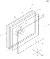
図1と図2に、本発明の実施の形態の表示入力装置1の基本構造が示されている。
図1に示すように、表示入力装置1は表示装置2を有している。表示装置2は、カラー液晶表示パネルやエレクトロルミネッセンス表示パネルなどである。表示装置2は金属製の枠体3の内部に保持されており、表示画面2aが枠体3の前面3aよりも後方(Z2方向)に後退して位置している。枠体3の前方にガラス板またはポリカーボネート板あるいはアクリル板などの透明なカバー板4が固定されており、その裏面(Z2側の面)に静電センサ10が貼着されている。
1 and 2 show a basic structure of a display input device 1 according to an embodiment of the present invention.
As shown in FIG. 1, the display input device 1 has a
静電センサ10は、PETなどの透明な樹脂フィルム11の表面に透明な電極層12が形成されている。
In the
または、前記カバー板4の裏面に電極層12が形成されて静電センサ10が構成されていてもよい。
Alternatively, the
表示入力装置1は、カバー板4のZ1側に向く最表面が操作面4aとなっている。
図3ないし図5には、表示入力装置1が上方から見た状態で示されている。これらの図に示されているように、表示装置2の表示画面2aとカバー板4の表面の静電センサ10の操作面4aとの間には、奥ゆき距離L1が存在している。
In the display input device 1, the outermost surface facing the Z1 side of the cover plate 4 is an
3 to 5 show the display input device 1 as viewed from above. As shown in these drawings, there is a depth L1 between the
図2に電極層12の配置が示されている。電極層12はITOなどの透明電極材料で形成されている。電極層12は配置に応じて第1の電極層12aと第2の電極層12bに区分される。第1の電極層12aと第2の電極層12bは同じ面積の菱形形状であり、互いに独立して形成されている。
The arrangement of the
第1の電極層12aは、Y1列、Y2列、Y3列、Y4列上に一定のピッチで並んで配置されている。第2の電極層12bは、X1列、X2列、X3列上に一定のピッチで並んで配置されている。
The
静電センサ10には、電極層12a,12bのそれぞれと絶縁された複数の配線層13が形成されている。複数の配線層13のそれぞれは、第1の電極層12aと第2の電極層12bに個別に導通している。
In the
図2に、静電センサ10に付随する回路がブロック図で示されている。
この回路には、複数の配線層13を選択する切換回路14が設けられ、切換回路14に駆動回路15と検出回路16が接続されている。検出回路16はA/D変換部17を介して制御部18に接続されている。
FIG. 2 is a block diagram showing a circuit associated with the
In this circuit, a
静電センサ10による検知動作の一例としては、切換回路14の切換え動作により、駆動回路15から第1の電極層12aに対してY1列、Y2列、Y3列、Y4列の順番で矩形波のパルス電圧が与えられる。このとき、切換回路14の切換え動作により、全ての第2の電極層12bが検出回路16に接続される。
As an example of the detection operation by the
隣接する第1の電極層12aと第2の電極層12bとの間に静電容量が形成されているため、駆動回路15から第1の電極層12aに与えられるパルス電圧の立ち上がり時と立下り時に第2の電極層12bに電流が流れ、その電流量が検出回路16で検出される。操作面4aのいずれかの箇所に、ほぼ接地電位の導電体の操作体である人の指が接近すると、第1の電極層12aまたは第2の電極層12bと指との間の静電容量が付加されることになり、第2の電極層12bを経て検出回路16で検出される電流量が変化する。
Since a capacitance is formed between the adjacent
検出回路16の検知信号はA/D変換部17でディジタル値に変換されて制御部18に与えられる。駆動回路15からY1列、Y2列、Y3列、Y4列の順で第1の電極層12aにパルス電圧が与えられているときに、第2の電極層12bからの検知電流の変化を監視することで、Y1列、Y2列、Y3列、Y4列のそれぞれの列毎の検出値が得られる。Y1列、Y2列、Y3列、Y4列のそれぞれの列の検出値は分布曲線として得られ、分布曲線のピーク位置がY方向での指の接近位置として求められる。
The detection signal of the
次に、切換回路14の切換え動作によって、第2の電極層12bに対してX1列、X2列、X3列の順番で駆動電力が印加されるとともに、全ての第1の電極層12aから検出される電流値が検出回路16に与えられる。その結果、X1列、X2列、X3列のそれぞれの列の検出値が分布曲線として得られ、分布曲線のピーク位置がX方向での指の接近位置として求められる。
Next, by the switching operation of the switching
この動作を繰り返すことで、操作面4aに設定されるX−Y座標上のどの位置に指が接近しているかを算出できる。
By repeating this operation, it is possible to calculate which position on the XY coordinate set on the
なお、静電センサ10の電極層12の配置は、図2に示す実施の形態に限られるものではなく、例えば、X方向に連続するX電極層とY方向に延びるY電極層が互いに絶縁されて形成されているものであってもよい。この場合の駆動・検出方法は、X電極層とY電極層の一方の電極層に順番にパルス電圧が印加され、このとき他方の電極層で検知される電流値が検出回路に与えられる。
The arrangement of the
本実施の形態での静電センサ10は、電極12a,12bの検知感度が高い、いわゆるホバータイプである。ホバータイプの静電センサは、第1の電極層12aまたは第2の電極層12bにパルス電圧が与えられたときに、操作面4aの前方(Z1方向)に強い電界が広がり、指Fが操作面4aの前方に離れた位置にあっても、指Fの位置をX−Y座標上の位置(座標点)として検出することができる。
The
検出回路16で検出される電流値の変化は、指が操作面4aから遠ざかっているほど小さく、操作面4aに接近するにしたがって大きくなる。そこで、制御部18では、2つのしきい値を設定して検出回路16からの検出出力を監視する。
The change in the current value detected by the
検出出力が第1のしきい値を超えたときに、操作面4aから前方Z1へ向けて予め決められた測定距離L2だけ離れた空間検知帯Hに指Fが至ったと判断され、さらに、空間検知帯Hに位置している指FのX−Y座標上の座標点である空間検知位置が算出される。
When the detection output exceeds the first threshold value, it is determined that the finger F has reached the space detection zone H separated from the
検出出力が第2のしきい値を超えたときに、指Fが操作面4aに接触したと判断され、指Fが操作面4aに接触したときの座標点である接触検知位置が算出される。指Fが操作面4aに接触したときの検出出力は非常に大きいため、指Fの接触により、メニュー表示やアイコン表示に対する確定操作の認識を確実に行うことができる。
When the detection output exceeds the second threshold value, it is determined that the finger F has touched the
なお、図3に示すように、操作面4aよりも距離L3だけ離れた位置での検出出力を第2のしきい値としてもよい(L3<L2)。この場合には、指Fを操作面4aに接触させることなく、操作面4aの前方において例えば円を描くように動作させることで、メニュー表示やアイコン表示に対する確定動作などを行うことができる。
In addition, as shown in FIG. 3, it is good also considering the detection output in the position left | separated by the distance L3 from the
図3には、表示入力装置1を自動車の車室内に設置した例が示されている。表示入力装置1は車室内の前方に固定され、表示画面2aと操作面4aが車室内に向けて前方(Z1方向)へ向けられている。
FIG. 3 shows an example in which the display input device 1 is installed in a vehicle cabin. The display input device 1 is fixed in front of the vehicle interior, and the
図3に、運転席に着座している人Paと助手席に着座している人Pbならびに後部座席の中央部に着座している人Pcが示され、これらの人Pa,Pb,Pcと、表示入力装置1との位置関係が示されている。本発明の表示入力装置1では、前記第1のしきい値と第2のしきい値を使用することで、どの人が操作しようとしているのかを判定することができる。 FIG. 3 shows a person Pa seated in the driver's seat, a person Pb seated in the passenger seat, and a person Pc seated in the center of the rear seat, and these persons Pa, Pb, Pc, A positional relationship with the display input device 1 is shown. In the display input device 1 of the present invention, it is possible to determine which person is trying to operate by using the first threshold value and the second threshold value.
図3では、助手席に着座している人Pbが表示入力装置1を見るときの視線が線VLで示されている。人Pcが表示入力装置1を操作しようとするとき、操作面4aに向けて移動させる指Fの移動方向は視線VLとほぼ一致することが多い。そこで、以下では、線VLを視線として説明することもあるし、指による操作方向線として説明することもある。
In FIG. 3, the line of sight when the person Pb sitting in the passenger seat looks at the display input device 1 is indicated by a line VL. When the person Pc tries to operate the display input device 1, the movement direction of the finger F moved toward the
指Fを操作面4aへ接近させるとき、制御部18では、検出出力が第1のしきい値を超えたときに指Fが空間検知帯Hに至ったと判断され、その指Fの位置が空間検知位置として認識され、その後、第2のしきい値を超えたときに指Fが操作面4aに触れたと判断され、指Fの接触検知位置が認識される。制御部18では、検出出力が第1のしきい値を超えたときと、第2のしきい値を超えたときの検出座標位置の変化から指Fがどの方向から接近しているのかを知ることができる。
When the finger F approaches the
図3の例では、X−Y座標上で空間検知位置S1が検知され、その後に接触検知位置S2が検知されており、制御部18では、助手席に着座している人Pcが指Fを操作方向線VLに沿って移動させて操作したと認識される。
In the example of FIG. 3, the space detection position S <b> 1 is detected on the XY coordinates, and then the contact detection position S <b> 2 is detected. In the
なお、図3に示すように、指Fが操作面4aの前方へ距離L3の位置に接近したときの検出出力が第2のしきい値とされているときは、指Fが空間検知帯Hを通過したときから、距離L3の位置に至るまでの検出座標点の変化を算出することで、指Fがどの方向から接近しているのかを知ることができる。
As shown in FIG. 3, when the detection output when the finger F approaches the position of the distance L3 forward of the
人の指Fは、操作面4aに向けて三次元空間を移動し、制御部18ではその移動方向が操作面4aに設定されるX−Y座標内の二次元方向のベクトルとして認識される。ただし、以下では説明を簡単にするため、指Fの移動方向を示すベクトルのうちのX方向に向く成分のみを指Fの移動方向ならびに移動距離とする。
The human finger F moves in the three-dimensional space toward the
また、以下では、操作面4aに接近する指Fが空間検知帯Hに至ったときと、指Fが操作面4aに接触したときの2つの検出出力を用いて指Fの接近方向を検出する例について説明するが、指Fが操作面4aに接触したときの検出出力に代えて、指Fが、操作面4a前方の距離L3の位置に接近したときの検出出力を使用することもできる。さらには、指Fが操作面4aに接近するときの複数の検出出力を使用することも可能である。あるいは、指Fが操作面4aに接近するときに、X−Y座標上で移動する検知出力の座標点の軌跡を連続的に追跡して、指Fの移動方向を算出してもよい。
In the following, the approach direction of the finger F is detected using two detection outputs when the finger F approaching the
指Fを操作面4aに接近させるときの指Fの移動方向を知ることにより、以下の制御が可能になる。
第1の制御としては、視線LVの視差による誤操作を防止することが可能である。
Knowing the moving direction of the finger F when the finger F is brought close to the
As the first control, it is possible to prevent an erroneous operation due to the parallax of the line of sight LV.
図4(A)は、図3と同様に表示入力装置1を上方から見た平面図であり、図4(B)は表示入力装置1を正面から見た正面図である。 4A is a plan view of the display input device 1 as viewed from above, as in FIG. 3, and FIG. 4B is a front view of the display input device 1 as viewed from the front.
図3と図4に示すように、助手席に着座している人Pbの視線VLでは、操作面4aと表示画面2aとの間にX−Y座標上の視差が発生する。この視差により、指Fで表示画面2aのボタン表示やアイコン表示などの操作目標表示V1に触れたつもりでも、指Fによる実際の接触検知位置S2と操作目標表示V1との間にX−Y座標面上での操作誤差距離W2が発生する。
As shown in FIGS. 3 and 4, parallax on the XY coordinates occurs between the
表示入力装置1では、表示画面2aの表示内容と、静電センサ10で設定されるX−Y座標上での検知位置とが、視差の無い方向から見たときに、互いに一致するように設定されている。そのため、指Fによる接触検知位置S2が操作目標表示V1の中心位置から大きくずれてしまうと、制御部18では操作目標表示V1が操作されたものと判別できず、むしろ操作目標表示V1の左に隣接する他の操作目標表示が操作されたと判断されることもある。
In the display input device 1, the display content of the
そこで、制御部18では、指Fが操作面4aに接触したときに、操作面4aまたは表示画面2aと平行な面内での空間検知位置S1と接触検知位置S2との検知ずれ距離W1が算出され、検知ずれ距離W1が予め決められている許容範囲を超えている場合に、検知位置の補正が行なわれる。
Therefore, the
図3と図4の例では、操作面4aから空間検知帯Hまでの測定距離L2と、検知ずれ距離W1とから、操作面4aまたは表示画面2aに対する指Fの進入角度θが算出される。そして、表示画面2aと操作面4aとの奥ゆき距離L1と進入角度θとから、補正すべき操作誤差距離W2が算出される。
In the example of FIGS. 3 and 4, the approach angle θ of the finger F with respect to the
図4の場合の補正としては、制御部18において、指Fが接触検知位置S2に接触したときに静電センサ10で検出された座標点のX座標(Xa)に対して、算出後の操作誤差距離W2が加算される。加算後の検出座標点のX座標は(Xa+W2=Xb)となり、静電センサ10で検出されたものとして処理される座標点(Xb)と操作目標表示V1とをデータ上で一致させることができる。
As a correction in the case of FIG. 4, the
または、図4(B)に示すように、操作面4aに設定されている初期のX0−Y0座標の原点O0を、接触検知位置S2に近づけるよう図示左方向へ、算出された操作誤差距離W2だけ移動させる。そして、移動後の点O1を原点とする新たなX1−Y1座標上で、接触検知位置S2の座標点を求める。移動後の原点O1から実際の接触検知位置S2までの距離は、初期の原点O0から操作目標表示V1までの距離と同じあるため、データ上で接触検知位置S2を操作目標表示V1に一致させることができる。
Alternatively, as shown in FIG. 4B, the operation error distance W2 calculated in the left direction in the figure so that the origin O0 of the initial X0-Y0 coordinates set on the
この補正により、人Pbの視線VLの視差によってあたかも操作しているかのように見えている操作目標表示V1に、接触検知位置S2をデータ上で一致させることができる。制御部18では、操作目標表示V1が操作されたものと認識して、操作目標表示V1であるボタン表示やアイコン表示に相当する制御動作が実行される。
By this correction, the contact detection position S2 can be matched in the data with the operation target display V1 that looks as if it is operated by the parallax of the line of sight VL of the person Pb. The
図5は、前記操作誤差距離W2が算出されたときの、他の補正方法を示している。
図5に示す補正方法では、表示画面2aと操作面4aとの奥ゆき距離L1と指Fの進入角度θとから、補正すべき操作誤差距離W2が算出されたときに、表示画面2aの表示画像の全体を図示右方向へ操作誤差距離W2だけ移動させる。
FIG. 5 shows another correction method when the operation error distance W2 is calculated.
In the correction method shown in FIG. 5, when the operation error distance W2 to be corrected is calculated from the depth L1 between the
図5(A)に示す状態では、人Pbは、斜めの視線VLによって、指Fが操作を希望する第1の操作目標表示V1に触れていると誤解しているが、図5(B)に示すように、実際の接触検知位置S1は、第1の操作目標表示V1ではなくその隣の第2の操作目標表示V2の前方に位置している。そこで、図5(C)に示すように、表示画面の全体を図示右方向へ移動させると、視線VLで見ている人Pbには、指Fが第1の操作目標表示V1ではなく、第2の操作目標表示V2に誤って触れていると気づくことができる。 In the state shown in FIG. 5A, the person Pb misunderstands that the finger F is touching the first operation target display V1 desired to be operated by the oblique line of sight VL, but FIG. As shown in FIG. 2, the actual contact detection position S1 is located not in the first operation target display V1 but in front of the adjacent second operation target display V2. Therefore, as shown in FIG. 5C, when the entire display screen is moved rightward in the figure, the finger F is not the first operation target display V1 but the first operation target display V1. It can be noticed that the operation target display V2 is touched by mistake.
よって、人Pbは指Fを操作面4aから離すことになり、改めて指Fで希望している第1の操作目標表示V2に指Fを触れる操作をやり直せるようになる。そのためには、指Fが操作面4aから離れたときに、表示画面を図示左方向へ距離W2だけ移動させて、元の表示状態に復帰させることが好ましい。
Therefore, the person Pb separates the finger F from the
なお、図4の補正方法において、接触検知位置S2の座標に、算出された操作誤差距離W2の正確な値を加算するのではなく、予め用意されている固定値を加算して、接触検知位置S2と操作目標表示V1とをデータ上で接近させるだけでもよい。または、X0−Y0座標の原点O0を移動させるときも、予め決められている固定値だけ移動させて、接触検知位置S2と操作目標表示V1とをデータ上で接近させてもよい。同様に、図5の補正においても、算出された操作誤差距離W2の正確な値で表示画像を移動させるのではなく、予め用意されている固定値だけ移動させてもよい。 In the correction method of FIG. 4, instead of adding the exact value of the calculated operation error distance W2 to the coordinates of the contact detection position S2, a fixed value prepared in advance is added to determine the contact detection position. It is only necessary to bring S2 and the operation target display V1 closer on the data. Alternatively, when the origin O0 of the X0-Y0 coordinates is moved, the contact detection position S2 and the operation target display V1 may be approximated on the data by moving by a predetermined fixed value. Similarly, in the correction of FIG. 5, the display image may be moved by a fixed value prepared in advance, instead of moving the display image with an accurate value of the calculated operation error distance W2.
固定値を使用した場合であっても、図4に示す補正方法では、接触検知位置S2と操作目標表示V1とをデータ上で接近させることができ、人Pbが操作しようとしている操作目標表示V1が操作されたものと判断される確率を高くすることができる。また、図5の補正方法では、人Pbが第1の操作目標表示V1以外の場所を操作していると気づくことができるようになる。 Even in the case where a fixed value is used, in the correction method shown in FIG. 4, the contact detection position S2 and the operation target display V1 can be approached on the data, and the operation target display V1 that the person Pb intends to operate is displayed. It is possible to increase the probability that it is determined that the is operated. Further, in the correction method of FIG. 5, it becomes possible to recognize that the person Pb is operating a place other than the first operation target display V1.
次に、第2の制御としては、操作した人がどの方角にいるかを認識して、操作者の方角に基づいた環境の条件を設定することが可能になる。 Next, as the second control, it is possible to recognize which direction the operated person is in and to set an environmental condition based on the direction of the operator.
図3は自動車の車室内の配置を示しているが、この場合には、操作面4aを操作する可能性のある人P1,P2,P2が着座している方角が3方向に限られている。そこで、操作面4aの前方に境界B1,B2で区切られた3つの領域が設定され、どの領域からの操作であるかを認識できるようにする。
FIG. 3 shows the arrangement of the interior of the automobile. In this case, the direction in which the persons P1, P2, and P2 who may operate the
制御部18では、空間検知位置S1の座標点と接触検知位置S2の座標点との検知ずれ距離W1が算出されるが、この値が所定値よりも小さいときは、境界B1とB2で挟まれた中央領域に着座している人Pcが操作面4aを操作したと判別される。検知ずれ距離W1が所定値よりも大きいときは、中央領域以外からの操作であると判定される。この場合には、空間検知位置S1の座標点から接触検知位置S2の座標点に至る座標点の移動方向に基づいて、境界B1よりも右側の領域にいる人Paの操作であるのか、境界B2よりも左側の人Pbによる操作であるのかが判別される。
The
この判別に基づいて、例えば、操作された操作目標表示V1が空調設備の温度設定や風量設定などであるときに、操作した人が着座していると判定された領域に近い送風口からの送風温度や風量を設定された値に設定することができる。または、操作された操作目標表示V1が音響装置の場合には、操作した人が着座していると判定された領域に向けての音量を操作された値に設定することなどが可能になる。 Based on this determination, for example, when the operated operation target display V1 is the temperature setting or air volume setting of the air conditioning equipment, the air is blown from the air blower near the area where the operated person is determined to be seated. The temperature and air volume can be set to the set values. Alternatively, when the operated operation target display V1 is a sound device, it is possible to set the volume for the region where it is determined that the operated person is seated to the operated value.
図6は本発明の他の実施の携帯の表示入力装置101を示す平面図である。
表示入力装置101に使用されている表示装置2と静電センサ10の構造は、図1ないし図5に示されたものと実質的に同じである。
FIG. 6 is a plan view showing a portable
The structures of the
図6では、表示入力装置101の表示画面2aと操作面4aとが上向きの姿勢で使用されている例を示している。
FIG. 6 illustrates an example in which the
操作しようとする人PA,PBは、操作面4aに対して異なる方角に位置している。前述のように、人の指が操作面4aに接触したときに、空間検知位置S1の座標点と接触検知位置S2の座標点とを検知することでどの方向から操作されたのかを知ることができる。図6の場合には、人PAが操作したのか人PBが操作したのかを判別することができる。
The persons PA and PB who are going to operate are located in different directions with respect to the
例えば、人PAが操作したと判定されたときは、人PAの指Fが接触した箇所の画像の説明文Eaが、人PAにとって読みやすい向きとなるように表示内容が切換えられる。また、人PBが操作したと判定されたときは、人PBの指Fで接触した箇所の画像の説明文Ebが、人PBにとって読みやすい向きとなるように表示内容が切換えられる。 For example, when it is determined that the person PA has operated, the display contents are switched so that the explanatory text Ea of the image where the finger F of the person PA touches is in a direction that is easy for the person PA to read. When it is determined that the person PB has operated, the display contents are switched so that the explanatory text Eb of the image of the part touched by the finger F of the person PB is in an easy-to-read direction for the person PB.
また、この表示入力装置101をゲーム装置として使用することができる。この場合には、どの方角の人が操作したかに応じて、ゲームの表示内容などが変更される。
The
F 指
H 空間検知帯
V1,V2 操作目標表示
L1 奥ゆき距離
S1 空間検知位置
S2 接触検知位置
W1 検知ずれ距離
W2 操作誤差距離
1 表示入力装置
2a 表示画面
10 静電センサ
4a 操作面
12a 第1の電極層
12b 第2の電極層
14 切換回路
15 駆動回路
16 検出回路
18 制御部
F finger H space detection band V1, V2 operation target display L1 depth distance S1 space detection position S2 contact detection position W1 detection deviation distance W2 operation error distance 1
Claims (6)
前記制御部では、
(a)前記静電センサからの検出出力に基づいて、前記操作面から所定の距離だけ離れた第1の検知位置と、それよりも前記操作面に近い位置または前記操作面に触れる位置である第2の検知位置の少なくとも2箇所の検知位置のそれぞれに前記操作体が至ったことが認識されるとともに、
(b)前記静電センサで設定される座標上での前記操作体の検出位置である検出座標が求められて、
(c)前記第1の検知位置で得られた前記検出座標と前記第2の検知位置で得られた前記検出座標とから、操作体が前記操作面に接近する移動方向が算出され、
(d)前記移動方向の算出値に基づいて、操作を行おうとする前記操作体の前記検出座標と、前記移動方向の延長上で前記表示画面に表示されている操作目標表示との操作誤差距離が求められ、
(e)前記操作誤差距離に基づいて、前記静電センサからの検出出力に対する補正動作が行われる
ことを特徴とする表示入力装置。 A display screen; an operation surface positioned in front of the display screen; an electrostatic sensor that detects the operation body that approaches or contacts the operation surface; and a control unit that processes a detection signal of the electrostatic sensor; In the display input device provided with
In the control unit,
(A) based on the detection output from the electrostatic sensor, first a detection position a predetermined distance away from the operation surface, in a position which to touch the position or the operation surface near the operation surface than the It is recognized that the operating body has reached each of at least two detection positions of a certain second detection position ,
(B) A detection coordinate which is a detection position of the operating body on a coordinate set by the electrostatic sensor is obtained,
From said detection coordinates obtained by the detected coordinates and the second detection position obtained in (c) before Symbol first detection position, the moving direction is calculated that operating body approaches to the operation surface,
(D) An operation error distance between the detected coordinates of the operating body to be operated based on the calculated value of the moving direction and the operation target display displayed on the display screen on the extension of the moving direction. Is required,
(E) A display input device in which a correction operation for a detection output from the electrostatic sensor is performed based on the operation error distance .
(f)前記操作体の移動方向に応じて、前記表示画面の表示内容を変更する補正動作が行われる
請求項1記載の表示入力装置。 Instead of (e) or in addition to (e),
(F) The display input device according to claim 1, wherein a correction operation is performed to change a display content of the display screen in accordance with a moving direction of the operating body.
Priority Applications (1)
| Application Number | Priority Date | Filing Date | Title |
|---|---|---|---|
| JP2013221395A JP6097670B2 (en) | 2013-10-24 | 2013-10-24 | Display input device |
Applications Claiming Priority (1)
| Application Number | Priority Date | Filing Date | Title |
|---|---|---|---|
| JP2013221395A JP6097670B2 (en) | 2013-10-24 | 2013-10-24 | Display input device |
Publications (2)
| Publication Number | Publication Date |
|---|---|
| JP2015082300A JP2015082300A (en) | 2015-04-27 |
| JP6097670B2 true JP6097670B2 (en) | 2017-03-15 |
Family
ID=53012837
Family Applications (1)
| Application Number | Title | Priority Date | Filing Date |
|---|---|---|---|
| JP2013221395A Active JP6097670B2 (en) | 2013-10-24 | 2013-10-24 | Display input device |
Country Status (1)
| Country | Link |
|---|---|
| JP (1) | JP6097670B2 (en) |
Families Citing this family (3)
| Publication number | Priority date | Publication date | Assignee | Title |
|---|---|---|---|---|
| US11137857B2 (en) * | 2014-12-26 | 2021-10-05 | Nikon Corporation | Detection device and program |
| WO2020026402A1 (en) * | 2018-08-02 | 2020-02-06 | 三菱電機株式会社 | On-vehicle information device and linking method with mobile terminal |
| JP7439699B2 (en) | 2020-08-27 | 2024-02-28 | 日本精機株式会社 | Vehicle display device |
Family Cites Families (8)
| Publication number | Priority date | Publication date | Assignee | Title |
|---|---|---|---|---|
| JP2000056929A (en) * | 1998-08-11 | 2000-02-25 | Amada Eng Center Co Ltd | Method and device for parallax correction of display type input device |
| JP2007331692A (en) * | 2006-06-19 | 2007-12-27 | Xanavi Informatics Corp | In-vehicle electronic equipment and touch panel device |
| JP5181792B2 (en) * | 2007-05-25 | 2013-04-10 | セイコーエプソン株式会社 | Display device and detection method |
| JP5141878B2 (en) * | 2007-11-06 | 2013-02-13 | 株式会社デンソー | Touch operation input device |
| JP5334618B2 (en) * | 2009-02-18 | 2013-11-06 | 三菱電機株式会社 | Touch panel device and input direction detection device |
| JP5768347B2 (en) * | 2010-09-07 | 2015-08-26 | ソニー株式会社 | Information processing apparatus, information processing method, and computer program |
| JP5595312B2 (en) * | 2011-03-15 | 2014-09-24 | 株式会社Nttドコモ | Display device, display device control method, and program |
| JP5773191B2 (en) * | 2011-05-31 | 2015-09-02 | オムロン株式会社 | Detection apparatus and method, and program |
-
2013
- 2013-10-24 JP JP2013221395A patent/JP6097670B2/en active Active
Also Published As
| Publication number | Publication date |
|---|---|
| JP2015082300A (en) | 2015-04-27 |
Similar Documents
| Publication | Publication Date | Title |
|---|---|---|
| JP6310787B2 (en) | Vehicle input device and vehicle cockpit module | |
| JP4450657B2 (en) | Display device | |
| JP5106268B2 (en) | Touch panel | |
| US10133421B2 (en) | Display stackups for matrix sensor | |
| JP6119679B2 (en) | Vehicle input device | |
| US9983741B2 (en) | Capacitive input device | |
| US9798429B2 (en) | Guard electrodes in a sensing stack | |
| JP6097670B2 (en) | Display input device | |
| US20160209956A1 (en) | Sensor structure and detection method | |
| WO2013153750A1 (en) | Display system, display device, and operation device | |
| JP6532128B2 (en) | Operation detection device | |
| JP2012212240A (en) | Touch panel system | |
| US10664152B2 (en) | Input apparatus for vehicle | |
| KR101933049B1 (en) | Underwater control method of camera | |
| JP5725368B2 (en) | Tactile display, operation input device, and operation input system | |
| JP2016051288A (en) | Vehicle input interface | |
| CN106020661B (en) | Track pad with internal bezel | |
| JP6520817B2 (en) | Vehicle control device | |
| KR101752315B1 (en) | Underwater control method of camera | |
| KR100481220B1 (en) | Touch panel apparatus and method for driving the same | |
| JP2015153004A (en) | Input device, and detection method thereof | |
| US20180373362A1 (en) | Operation device | |
| EP2853987B1 (en) | Head up display with non contact gesture detection. | |
| US11907472B2 (en) | Detection device and display unit | |
| JP2024051341A (en) | Input display device |
Legal Events
| Date | Code | Title | Description |
|---|---|---|---|
| A621 | Written request for application examination |
Free format text: JAPANESE INTERMEDIATE CODE: A621 Effective date: 20160201 |
|
| A977 | Report on retrieval |
Free format text: JAPANESE INTERMEDIATE CODE: A971007 Effective date: 20161130 |
|
| A131 | Notification of reasons for refusal |
Free format text: JAPANESE INTERMEDIATE CODE: A131 Effective date: 20161206 |
|
| A521 | Request for written amendment filed |
Free format text: JAPANESE INTERMEDIATE CODE: A523 Effective date: 20170201 |
|
| TRDD | Decision of grant or rejection written | ||
| A01 | Written decision to grant a patent or to grant a registration (utility model) |
Free format text: JAPANESE INTERMEDIATE CODE: A01 Effective date: 20170214 |
|
| A61 | First payment of annual fees (during grant procedure) |
Free format text: JAPANESE INTERMEDIATE CODE: A61 Effective date: 20170220 |
|
| R150 | Certificate of patent or registration of utility model |
Ref document number: 6097670 Country of ref document: JP Free format text: JAPANESE INTERMEDIATE CODE: R150 |
|
| S533 | Written request for registration of change of name |
Free format text: JAPANESE INTERMEDIATE CODE: R313533 |
|
| R350 | Written notification of registration of transfer |
Free format text: JAPANESE INTERMEDIATE CODE: R350 |