JP6096862B2 - Seal / pump-up device structure - Google Patents
Seal / pump-up device structure Download PDFInfo
- Publication number
- JP6096862B2 JP6096862B2 JP2015215392A JP2015215392A JP6096862B2 JP 6096862 B2 JP6096862 B2 JP 6096862B2 JP 2015215392 A JP2015215392 A JP 2015215392A JP 2015215392 A JP2015215392 A JP 2015215392A JP 6096862 B2 JP6096862 B2 JP 6096862B2
- Authority
- JP
- Japan
- Prior art keywords
- shaft tube
- lid
- flow path
- container body
- lower shaft
- Prior art date
- Legal status (The legal status is an assumption and is not a legal conclusion. Google has not performed a legal analysis and makes no representation as to the accuracy of the status listed.)
- Active
Links
- 239000000853 adhesive Substances 0.000 claims description 65
- 230000001070 adhesive effect Effects 0.000 claims description 65
- 239000000126 substance Substances 0.000 claims description 33
- 238000002347 injection Methods 0.000 claims description 8
- 239000007924 injection Substances 0.000 claims description 8
- 230000002093 peripheral effect Effects 0.000 claims description 3
- 239000003795 chemical substances by application Substances 0.000 claims 1
- 238000007789 sealing Methods 0.000 description 4
- 238000010586 diagram Methods 0.000 description 3
- 230000009969 flowable effect Effects 0.000 description 1
- 238000005086 pumping Methods 0.000 description 1
Images


Classifications
-
- B—PERFORMING OPERATIONS; TRANSPORTING
- B29—WORKING OF PLASTICS; WORKING OF SUBSTANCES IN A PLASTIC STATE IN GENERAL
- B29C—SHAPING OR JOINING OF PLASTICS; SHAPING OF MATERIAL IN A PLASTIC STATE, NOT OTHERWISE PROVIDED FOR; AFTER-TREATMENT OF THE SHAPED PRODUCTS, e.g. REPAIRING
- B29C73/00—Repairing of articles made from plastics or substances in a plastic state, e.g. of articles shaped or produced by using techniques covered by this subclass or subclass B29D
- B29C73/16—Auto-repairing or self-sealing arrangements or agents
- B29C73/166—Devices or methods for introducing sealing compositions into articles
-
- B—PERFORMING OPERATIONS; TRANSPORTING
- B05—SPRAYING OR ATOMISING IN GENERAL; APPLYING FLUENT MATERIALS TO SURFACES, IN GENERAL
- B05B—SPRAYING APPARATUS; ATOMISING APPARATUS; NOZZLES
- B05B11/00—Single-unit hand-held apparatus in which flow of contents is produced by the muscular force of the operator at the moment of use
- B05B11/0005—Components or details
- B05B11/0008—Sealing or attachment arrangements between sprayer and container
-
- B—PERFORMING OPERATIONS; TRANSPORTING
- B29—WORKING OF PLASTICS; WORKING OF SUBSTANCES IN A PLASTIC STATE IN GENERAL
- B29C—SHAPING OR JOINING OF PLASTICS; SHAPING OF MATERIAL IN A PLASTIC STATE, NOT OTHERWISE PROVIDED FOR; AFTER-TREATMENT OF THE SHAPED PRODUCTS, e.g. REPAIRING
- B29C73/00—Repairing of articles made from plastics or substances in a plastic state, e.g. of articles shaped or produced by using techniques covered by this subclass or subclass B29D
- B29C73/02—Repairing of articles made from plastics or substances in a plastic state, e.g. of articles shaped or produced by using techniques covered by this subclass or subclass B29D using liquid or paste-like material
- B29C73/025—Repairing of articles made from plastics or substances in a plastic state, e.g. of articles shaped or produced by using techniques covered by this subclass or subclass B29D using liquid or paste-like material fed under pressure
-
- B—PERFORMING OPERATIONS; TRANSPORTING
- B05—SPRAYING OR ATOMISING IN GENERAL; APPLYING FLUENT MATERIALS TO SURFACES, IN GENERAL
- B05B—SPRAYING APPARATUS; ATOMISING APPARATUS; NOZZLES
- B05B11/00—Single-unit hand-held apparatus in which flow of contents is produced by the muscular force of the operator at the moment of use
- B05B11/0005—Components or details
- B05B11/0037—Containers
- B05B11/0039—Containers associated with means for compensating the pressure difference between the ambient pressure and the pressure inside the container, e.g. pressure relief means
- B05B11/0044—Containers associated with means for compensating the pressure difference between the ambient pressure and the pressure inside the container, e.g. pressure relief means compensating underpressure by ingress of atmospheric air into the container, i.e. with venting means
-
- B—PERFORMING OPERATIONS; TRANSPORTING
- B05—SPRAYING OR ATOMISING IN GENERAL; APPLYING FLUENT MATERIALS TO SURFACES, IN GENERAL
- B05B—SPRAYING APPARATUS; ATOMISING APPARATUS; NOZZLES
- B05B11/00—Single-unit hand-held apparatus in which flow of contents is produced by the muscular force of the operator at the moment of use
- B05B11/0005—Components or details
- B05B11/0089—Dispensing tubes
-
- B—PERFORMING OPERATIONS; TRANSPORTING
- B05—SPRAYING OR ATOMISING IN GENERAL; APPLYING FLUENT MATERIALS TO SURFACES, IN GENERAL
- B05B—SPRAYING APPARATUS; ATOMISING APPARATUS; NOZZLES
- B05B7/00—Spraying apparatus for discharge of liquids or other fluent materials from two or more sources, e.g. of liquid and air, of powder and gas
- B05B7/24—Spraying apparatus for discharge of liquids or other fluent materials from two or more sources, e.g. of liquid and air, of powder and gas with means, e.g. a container, for supplying liquid or other fluent material to a discharge device
- B05B7/2489—Spraying apparatus for discharge of liquids or other fluent materials from two or more sources, e.g. of liquid and air, of powder and gas with means, e.g. a container, for supplying liquid or other fluent material to a discharge device an atomising fluid, e.g. a gas, being supplied to the discharge device
- B05B7/2491—Spraying apparatus for discharge of liquids or other fluent materials from two or more sources, e.g. of liquid and air, of powder and gas with means, e.g. a container, for supplying liquid or other fluent material to a discharge device an atomising fluid, e.g. a gas, being supplied to the discharge device characterised by the means for producing or supplying the atomising fluid, e.g. air hoses, air pumps, gas containers, compressors, fans, ventilators, their drives
-
- B—PERFORMING OPERATIONS; TRANSPORTING
- B29—WORKING OF PLASTICS; WORKING OF SUBSTANCES IN A PLASTIC STATE IN GENERAL
- B29L—INDEXING SCHEME ASSOCIATED WITH SUBCLASS B29C, RELATING TO PARTICULAR ARTICLES
- B29L2030/00—Pneumatic or solid tyres or parts thereof
Landscapes
- Engineering & Computer Science (AREA)
- Mechanical Engineering (AREA)
- General Engineering & Computer Science (AREA)
- Coating Apparatus (AREA)
- Nozzles (AREA)
Description
本発明は、シール・ポンプアップ装置構造に関し、特に、パンク修理用の化学接着剤が充填され、シール・ポンプアップ装置の容器本体が蓋体と結合され、蓋体には、2本のマニホールドが設けられ、そのうち一方のマニホールドは、空気圧縮機が発生させた高圧エアの供給を受け、他方のマニホールドは、シール・ポンプアップ装置内の化学接着剤を出力するのに用いられ、つまみを回転させて蓋体内に収容された細長体を押動し、連通チャネルのバルブプラグを封止し、高圧エアが直接連通チャネルから出力され、化学接着剤の上表面を押圧し、下軸管の内流路、接着剤排出マニホールド及び直列接続ホースを介し、化学接着剤が破損したタイヤのノズルに供給され、安全かつ容易に短時間でパンク修理及び気体注入が行える、シール・ポンプアップ装置構造に関する。 The present invention relates to a seal / pump-up device structure, and in particular, is filled with a chemical adhesive for puncture repair, a container body of the seal / pump-up device is coupled to a lid, and two manifolds are formed on the lid. One of the manifolds is supplied with high-pressure air generated by an air compressor, and the other manifold is used to output chemical adhesive in the seal pump-up device, and rotates the knob. The elongated body accommodated in the lid is pushed, the valve plug of the communication channel is sealed, high pressure air is output directly from the communication channel, presses the upper surface of the chemical adhesive, and the inner flow of the lower shaft pipe Through the road, the adhesive discharge manifold and the series connection hose, the chemical adhesive is supplied to the damaged tire nozzle, enabling safe and easy puncture repair and gas injection in a short time. On Npuappu the device structure.
大部分のシール・ポンプアップ装置は、蓋体、容器本体及び管体から構成される。容器本体内には、パンク修理用の化学接着剤が充填される。蓋体には、2本のマニホールドが設けられ、そのうち一方のマニホールドは、空気圧縮機が発生させた高圧エアの供給を受け、他方のマニホールドを介して化学接着剤が出力される。容器本体に蓋体が結合された後、管体が容器本体内に収納され、空気圧縮機が発生させた高圧エアが管体を介して出力され、化学接着剤を押出し、接着剤排出マニホールドを介して流出させ、接続ホース及びノズルを介して破損したタイヤ内へ供給される。 Most seal / pump-up devices are composed of a lid, a container body and a tube. The container body is filled with a chemical adhesive for puncture repair. The lid is provided with two manifolds, one of which receives supply of high-pressure air generated by an air compressor and outputs a chemical adhesive via the other manifold. After the lid is joined to the container body, the tube body is housed in the container body, high pressure air generated by the air compressor is output through the tube body, the chemical adhesive is extruded, and the adhesive discharge manifold is Through the connecting hose and nozzle and fed into the damaged tire.
本発明の主な目的は、安全かつ容易に短時間でパンク修理、気体注入を行うシール・ポンプアップ装置構造を提供することにある。 A main object of the present invention is to provide a seal / pump-up device structure that performs puncture repair and gas injection safely and easily in a short time.
上記課題を解決するために、本発明の第1の形態によれば、容器本体、蓋体、バルブプラグ及び回転部材を備えたシール・ポンプアップ装置構造であって、前記容器本体には、化学接着剤が充填され、前記蓋体は、前記容器本体の開口に結合され、前記バルブプラグは、前記容器本体内に前記化学接着剤が既に充填された初期状態で、高圧エアの吸気流路及び前記化学接着剤の接着剤排出流路を封止し、前記回転部材を前記蓋体に対して回転させると、前記吸気流路及び前記接着剤排出流路を封止していた前記バルブプラグが押動されて外れ、前記吸気流路及び前記接着剤排出流路が流通可能な状態となり、空気圧縮機が発生させた高圧エアが前記吸気流路を介して前記容器本体内へ進入し、前記化学接着剤が前記接着剤排出流路から流出されることを特徴とするシール・ポンプアップ装置構造が提供される。 In order to solve the above problems, according to a first aspect of the present invention, there is provided a seal / pump-up device structure including a container main body, a lid, a valve plug, and a rotating member. The lid is coupled to the opening of the container body, and the valve plug is in an initial state in which the chemical adhesive is already filled in the container body, When the adhesive discharge channel of the chemical adhesive is sealed and the rotating member is rotated with respect to the lid, the valve plug that has sealed the intake channel and the adhesive discharge channel is Pushed and removed, the intake flow path and the adhesive discharge flow path become flowable, high pressure air generated by an air compressor enters the container body through the intake flow path, Chemical adhesive flows out of the adhesive discharge channel Seal pumping device structures characterized by Rukoto is provided.
前記容器本体は、内空状のチャンバを有するとともに、一端に開口が形成され、他端に底端ベースが形成され、前記容器本体の前記チャンバには、パンク修理用の前記化学接着剤が充填され、前記蓋体には、互いに連通する上軸管及び下軸管が上下端に延設され、前記上軸管及び前記下軸管内には、内流路が形成され、前記上軸管には、2本のマニホールドが設けられ、そのうち一方の前記マニホールドは、前記空気圧縮機が発生させた高圧エアの供給を受け、他方のマニホールドは、前記容器本体内の前記化学接着剤を出力し、前記蓋体は、前記容器本体の前記開口に螺着され、前記内流路には、前記下軸管の底端を介して非円柱体の細長体が挿入され、前記バルブプラグは、内流通室を有するとともに、一端に開放式の開口が形成され、他端に段差プラグが形成され、前記バルブプラグは、前記開放式の開口を介して下から上方向へかけて前記蓋体の前記下軸管に嵌合されると、前記段差プラグが前記細長体に当接されるとともに、前記下軸管の底端に密着され、前記回転部材は、前記蓋体の前記上軸管に嵌合されるハット型形状のつまみを含み、前記つまみを回転させると、前記蓋体内に収納された細長体によりバルブプラグが押動され、高圧エアが直接下方へ出力されて前記化学接着剤の上表面を押圧すると、前記化学接着剤が前記下軸管の前記内流路、接着剤排出マニホールド及び直列接続ホースへ進入し、破損したタイヤのノズルへ供給され、安全にパンク修理及び気体注入を行うことが好ましい。 The container body has an inner chamber, an opening is formed at one end, a bottom end base is formed at the other end, and the chamber of the container body is filled with the chemical adhesive for puncture repair. In the lid body, an upper shaft tube and a lower shaft tube communicating with each other are extended to upper and lower ends, and an inner flow path is formed in the upper shaft tube and the lower shaft tube, and the upper shaft tube Is provided with two manifolds, one of which is supplied with high-pressure air generated by the air compressor, and the other manifold outputs the chemical adhesive in the container body, The lid body is screwed into the opening of the container body, a non-cylindrical elongated body is inserted into the inner flow path through the bottom end of the lower shaft tube, and the valve plug A chamber and an open opening at one end; A step plug is formed at an end, and when the valve plug is fitted to the lower shaft tube of the lid body from below to above through the open-type opening, the step plug is connected to the elongated body. The rotating member includes a hat-shaped knob fitted to the upper shaft tube of the lid, and the knob is rotated when the knob is rotated. When the valve plug is pushed by the elongated body housed in the lid body, and the high pressure air is directly output downward to press the upper surface of the chemical adhesive, the chemical adhesive is removed from the inner shaft of the lower shaft tube. It is preferable to enter the flow path, the adhesive discharge manifold and the series connection hose and supply to the damaged tire nozzle to safely perform puncture repair and gas injection.
前記容器本体の前記開口には、雄ねじ部が設けられ、前記チャンバの底層に設けられた底端ベースは、凹部を有し、前記蓋体の内面には、ガスケットを収納する環状凹溝が凹設され、前記上軸管の側辺には、水平に延びた少なくとも1つの短柱体が延設され、前記短柱体の横断面は、非完全円形状であり、前記短柱体の外縁には、直角部が形成され、前記上軸管は、吸気マニホールド及び接着剤排出マニホールドの2つのマニホールドを有し、前記吸気マニホールド内には、吸気流路が設けられ、前記吸気流路は、連通チャネルを介して前記容器本体の前記チャンバと連通し、前記蓋体の内側には、前記連通チャネルに挿入される円形凸座が突設され、前記接着剤排出マニホールド内には、接着剤排出流路が設けられ、前記接着剤排出流路は、前記上軸管の前記内流路と連通し、前記上軸管の前記内流路の口径は、前記下軸管の前記内流路の口径より小さく、前記上軸管及び前記下軸管の前記内流路の境界には、放射線状を呈して傾いた円錐壁が形成されることが好ましい。 The opening of the container body is provided with a male threaded portion, the bottom end base provided in the bottom layer of the chamber has a recess, and the inner surface of the lid has an annular groove for receiving a gasket. At least one short column that extends horizontally is provided on the side of the upper shaft tube, and the cross section of the short column has a non-perfect circular shape, and the outer edge of the short column , A right angle portion is formed, and the upper shaft pipe has two manifolds of an intake manifold and an adhesive discharge manifold, an intake passage is provided in the intake manifold, and the intake passage is A circular convex seat inserted into the communication channel protrudes from the inside of the lid, and communicates with the chamber of the container body through the communication channel. A flow path is provided, and the adhesive discharge flow path is The diameter of the inner flow path of the upper shaft pipe is smaller than the diameter of the inner flow path of the lower shaft pipe, and communicates with the inner flow path of the upper shaft pipe. It is preferable that a conical wall inclined in a radial shape is formed at the boundary of the inner flow path.
前記細長体は、管外径が大きめな始端部を有し、前記始端部には、Oリングが嵌合される環状凹溝が形成され、前記細長体上には、フランジが設けられ、前記フランジ上には、複数の内凹溝が形成され、前記細長体は、前記始端部から前記蓋体の前記下軸管に底端を介して挿入され、前記Oリングが嵌合された前記細長体の前記始端部は、前記下軸管内の円錐壁に沿うため前記上軸管の前記内流路への挿入が容易であり、前記細長体の前記始端部が前記上軸管の前記内流路に挿入されると、前記細長体の前記フランジが前記下軸管内の前記円錐壁に当接され、前記上軸管の頂端から前記細長体は突出されず、前記細長体が前記上軸管及び前記下軸管の前記内流路中に完全に収容されることが好ましい。 The elongated body has a starting end portion having a large tube outer diameter, and an annular concave groove into which an O-ring is fitted is formed at the starting end portion, and a flange is provided on the elongated body, A plurality of inner concave grooves are formed on the flange, and the elongated body is inserted from the starting end portion into the lower shaft tube of the lid body through the bottom end, and the elongated body is fitted with the O-ring. Since the start end of the body is along the conical wall in the lower shaft tube, the upper shaft tube can be easily inserted into the inner flow path, and the start end of the elongated body is the inner flow of the upper shaft tube. When inserted into the path, the flange of the elongated body comes into contact with the conical wall in the lower shaft tube, the elongated body does not protrude from the top end of the upper shaft tube, and the elongated body is not in the upper shaft tube. And it is preferable to be completely accommodated in the inner flow path of the lower shaft tube.
前記バルブプラグは、一方の端部に、開放式の開口が形成され、他方の端部に、間隔をあけて配列された複数の縦板が延設され、2つの前記縦板間には、スリットが形成され、前記縦板により画成された内縁側には、段差プラグが設けられ、前記開口端の前記バルブプラグの外縁には、縦体が上方へ向かって延設され、前記縦体の末端には、凹部を有するアッパープラグが設けられ、前記アッパープラグの前記凹部から中心ピンが延出し、前記バルブプラグは、前記開放式の開口を介し、下から上方向へかけて前記蓋体の前記下軸管に嵌合され、前記凹部には、前記蓋体内側の前記凸座が嵌合され、前記アッパープラグの前記中心ピンにより、前記連通チャネルが封止されることが好ましい。 In the valve plug, an open-type opening is formed at one end, and a plurality of vertical plates arranged at intervals are extended at the other end, and between the two vertical plates, A slit is formed and a step plug is provided on the inner edge side defined by the vertical plate, and a vertical body extends upward on an outer edge of the valve plug at the opening end. An upper plug having a recess is provided at an end of the upper plug, a center pin extends from the recess of the upper plug, and the valve plug extends from the bottom to the top through the open-type opening. Preferably, the convex seat inside the lid is fitted into the recess, and the communication channel is sealed by the center pin of the upper plug.
前記つまみの外縁には、互いに対をなす2つのプレート部が設けられ、前記つまみの内面側中央部には、中心柱が設けられ、前記つまみは、周壁に少なくとも1つのトラック溝が設けられ、前記トラック溝の一端は、前記つまみの下端を始点として用い、開口端が形成され、他端が上昇状態で上方へ延出して封止端が形成され、前記封止端に近接した前記トラック溝上には、斜めに延びた係合ピンが設けられることが好ましい。 The outer edge of the knob is provided with two pairs of plates that are paired with each other, the central part on the inner surface side of the knob is provided with a central column, and the knob is provided with at least one track groove on the peripheral wall, One end of the track groove uses the lower end of the knob as a starting point, an open end is formed, and the other end extends upward in a raised state to form a sealed end. It is preferable that an engaging pin extending obliquely is provided.
以下、本発明の実施形態について図に基づいて説明する。なお、これによって本発明が限定されるものではない。 Hereinafter, embodiments of the present invention will be described with reference to the drawings. Note that the present invention is not limited thereby.
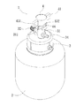
本発明の一実施形態に係るシール・ポンプアップ装置1構造は、特に、空気圧縮機と組み合わせて使用するシール・ポンプアップ装置1を含む。シール・ポンプアップ装置1の容器本体2内には、化学接着剤26が収容される。蓋体3は、容器本体2の開口21に結合される。バルブプラグ5は、吸気流路33及び接着剤排出流路35を封止し、回転部材が蓋体3で回転されると、吸気流路33及び接着剤排出流路35を封止していたバルブプラグ5が押動されて外れて吸気流路33及び接着剤排出流路35が流通し、空気圧縮機が発生させた高圧エアが吸気流路33を介して容器本体2内へ進入し、化学接着剤26が接着剤排出流路35から流出する。
The structure of the seal / pump-up
以下、図1〜図3に基づいて本発明のシール・ポンプアップ装置構造を詳細に説明する。図1〜図3に示すように、本発明のシール・ポンプアップ装置1構造は、容器本体2及び蓋体3を含む。
Hereinafter, the structure of the seal / pump-up device of the present invention will be described in detail with reference to FIGS. As shown in FIGS. 1 to 3, the structure of the seal / pump-up
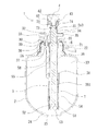
容器本体2は、内空状のチャンバ23を有するとともに、一端に開口21が形成され、他端に底端ベース25が形成される。容器本体2の開口21には、雄ねじ部22が設けられる。チャンバ23の底層に設けられた底端ベース25は、凹部24を有する。容器本体2のチャンバ23には、パンク修理用の化学接着剤が充填される。
The
蓋体3は、容器本体2の開口21に螺着される。蓋体3の内面には、ガスケット6を収納する環状凹溝30が凹設されている。蓋体3と容器本体2とが結合される際、ガスケット6により容器本体2の開口21端に蓋体3が螺合された際の安定性及び密閉性を向上させることができる。蓋体3の上下端には、互いに連通した上軸管31及び下軸管36が延設される。上軸管31内には、内流路313が形成される。下軸管36内には、内流路361が形成される。内流路313と内流路361とは連通する。上軸管31の側辺には、水平に延びた少なくとも1つの短柱体311が延設されている。短柱体311の横断面は、非完全円形状である。短柱体311の外縁には、直角部312が形成されている。上軸管31は、吸気マニホールド32及び接着剤排出マニホールド34を有する。吸気マニホールド32内には、吸気流路33が設けられる。吸気流路33は、連通チャネル39を介して容器本体2のチャンバ23と連通する。蓋体3の内側には、連通チャネル39と連通する円形凸座38が突設され、接着剤排出マニホールド34内には、接着剤排出流路35が設けられている。接着剤排出流路35は、上軸管31の内流路313と連通する。上軸管31の内流路313の口径は、下軸管36の内流路361の口径より小さい。上軸管31及び下軸管36の内流路313,361の境界には、放射線状を呈して傾いた円錐壁37が形成される。
The
非円柱体の細長体7は、管外径が大きめな始端部72を有する。始端部72には、Oリング74が嵌合される環状凹溝73が形成されている。細長体7上には、フランジ71が設けられる。フランジ71上には、複数の内凹溝710が形成される。細長体7は、その始端部72により蓋体3の下軸管36の底端を介して挿入され、Oリング74が嵌合された細長体7の始端部72が、下軸管36内の円錐壁37に沿うため、上軸管31の内流路313へ容易に挿入させることができる。細長体7の始端部72が上軸管31の内流路313に挿入された後、細長体7のフランジ71が下軸管36内の円錐壁37に当接されるため、上軸管31の頂端から細長体7が突出されることを防ぎ、細長体7が上軸管31及び下軸管36の内流路313,361に完全に収容される。
The non-cylindrical
内流通室54を有するバルブプラグ5は、一方の端部に、開放式の開口50が形成され、他方の端部に、間隔をあけて配列された複数の縦板51が延設される。2つの縦板51間には、スリット52が形成される。複数の縦板51により画成された内縁側には、段差プラグ53が設けられる。開口50端のバルブプラグ5の外縁からは、縦体55が上方に延出する。縦体55の末端には、凹部57を有するアッパープラグ56が設けられる。アッパープラグ56の凹部57からは、中心ピン58が延出する。バルブプラグ5は、開放式の開口50を介し、下から上方向へかけて蓋体3の下軸管36に嵌合される。凹部57には、蓋体3内側の凸座38が嵌合される。アッパープラグ56の中心ピン58は、前述した連通チャネル39を封止する。
The
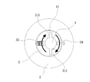
本明細書において、「回転部材」とは、回転又は回動可能な部材を意味する。本実施形態の回転部材は、ハット型形状のつまみ4でもよい。つまみ4の外縁には、互いに対をなす2つのプレート部41が設けられ、つまみ4の内面側中央部には、中心柱42が設けられる。つまみ4は、周壁に少なくとも1つのトラック溝43が設けられ、その一端はつまみ4の下端を始点として用いられ、開口端431が形成され、他端が上昇状態で上方へ延出して封止端432が形成される。封止端432に近接したトラック溝43上には、斜めに延びた係合ピン44が設けられる。つまみ4は、蓋体3の上軸管31に嵌合される。
In this specification, the “rotating member” means a member that can rotate or rotate. The rotary member of this embodiment may be a hat-shaped knob 4. Two
本発明のシール・ポンプアップ装置1の初期状態は、図7に示すように、バルブプラグ5のアッパープラグ56により前述した蓋体3の連通チャネル39を封止し、段差プラグ53が細長体7に当接されるとともに、下軸管36に密着され、連通チャネル39及び蓋体3の上軸管31及び下軸管36内の内流路313,361は、容器本体2のチャンバ23とは連通しない。シール・ポンプアップ装置1が気体注入及び接着剤注入を行う説明図を図8に示す。つまみ4が蓋体3の上軸管31に嵌合され、上軸管31の短柱体311がトラック溝43の開口端431に沿って挿入され、トラック溝43に沿ってつまみ4が回転され(図6を参照する)、上軸管31の短柱体311がトラック溝43の封止端432に当接され、短柱体311の直角部312が係合ピン44上に係合されると、つまみ4が固定状態となり、逆回転することを防ぐ。上軸管31の短柱体311が、固定状態となっているため、つまみ4のトラック溝43が上昇状態となり、つまみ4が回転されると、つまみ4が実質上、上昇状態と反対に下降し、つまみ4の中心柱42が細長体7の始端部72に当接されるため、下降するつまみ4は、細長体7を下方へ変位させるとともに、細長体7に力が加わり、細長体7下端の段差プラグ53に当接され、バルブプラグ5全体を押動されて下方へ変位させ、バルブプラグ5のアッパープラグ56と蓋体3の連通チャネル39、バルブプラグ5の段差プラグ53と下軸管36とが分離され、連通チャネル39及び蓋体3の上軸管31及び下軸管36内の内流路313,361と、容器本体2のチャンバ23とが連通し、高圧エアが吸気マニホールド32の吸気流路33、連通チャネル39から直接入力され、化学接着剤26の上表面を押圧し、化学接着剤26がバルブプラグ5の縦板51間のスリット52(図4を参照する)を介し、下軸管36の内流路361に進入し、細長体7上のフランジ71の内凹溝710を通過し(図5を参照する)、接着剤排出マニホールド34の接着剤排出流路35及び直列接続ホースが、破損したノズルに連通され、かつ、パンク修理を行った後に残った化学接着剤26が容器本体2の底端ベース25に形成された凹部24へ流入して集められ、残った化学接着剤26がバルブプラグ5の縦板51間のスリット52を介し、下軸管36の内流路361、接着剤排出マニホールド34の接着剤排出流路35及び直列接続ホースへ進入し、破損したタイヤのノズルへ供給され、容器本体2の底端ベース25に化学接着剤26が残留することを防ぐことができる上、安全にパンク修理及び気体注入を行うことができる。
As shown in FIG. 7, the initial state of the seal / pump-up
上述したことから分かるように、本発明のシール・ポンプアップ装置1の容器本体2には、蓋体が結合される。蓋体3には、2本のマニホールドが設けられ、そのうち一方のマニホールドは、空気圧縮機が発生させた高圧エアの供給を受け、他方のマニホールドは、シール・ポンプアップ装置1内の化学接着剤26を出力するのに用い、つまみ4を回転させて蓋体3内の細長体7を押動し、連通チャネル39のバルブプラグ5を封止し、高圧エアが連通チャネル39から直接出力され、化学接着剤26の上表面を押圧し、化学接着剤26が下軸管36の内流路361、接着剤排出マニホールド34及び直列接続ホースを介し、破損したタイヤのノズルに供給されるため、安全かつ容易に短時間でパンク修理、気体注入を行うことができる。
As can be seen from the above, a lid is coupled to the
1 シール・ポンプアップ装置
2 容器本体
3 蓋体
4 つまみ
5 バルブプラグ
6 ガスケット
7 細長体
21 開口
22 雄ねじ部
23 チャンバ
24 凹部
25 底端ベース
26 化学接着剤
30 環状凹溝
31 上軸管
32 吸気マニホールド
33 吸気流路
34 接着剤排出マニホールド
35 接着剤排出流路
36 下軸管
37 円錐壁
38 凸座
39 連通チャネル
41 プレート部
42 中心柱
43 トラック溝
44 係合ピン
50 開口
51 縦板
52 スリット
53 段差プラグ
54 内流通室
55 縦体
56 アッパープラグ
57 凹部
58 中心ピン
71 フランジ
72 始端部
73 環状凹溝
74 Oリング
311 短柱体
312 直角部
313 内流路
361 内流路
431 開口端
432 封止端
710 内凹溝
DESCRIPTION OF
Claims (5)
前記容器本体には、化学接着剤が充填され、
前記蓋体は、前記容器本体の開口に結合され、
前記バルブプラグは、前記容器本体内に前記化学接着剤が既に充填された初期状態で、高圧エアの吸気流路及び前記化学接着剤の接着剤排出流路を封止し、
前記回転部材を前記蓋体に対して回転させると、前記吸気流路及び前記接着剤排出流路を封止していた前記バルブプラグが押動されて外れ、前記吸気流路及び前記接着剤排出流路が流通可能な状態となり、空気圧縮機が発生させた高圧エアが前記吸気流路を介して前記容器本体内へ進入し、前記化学接着剤が前記接着剤排出流路から流出され、
前記容器本体は、内空状のチャンバを有するとともに、一端に開口が形成され、他端に底端ベースが形成され、
前記容器本体の前記チャンバには、パンク修理用の前記化学接着剤が充填され、
前記蓋体には、互いに連通する上軸管及び下軸管が上下端に延設され、前記上軸管及び前記下軸管内には、内流路が形成され、
前記上軸管には、2本のマニホールドが設けられ、そのうち一方の前記マニホールドは、前記空気圧縮機が発生させた高圧エアの供給を受け、他方のマニホールドは、前記容器本体内の前記化学接着剤を出力し、前記蓋体は、前記容器本体の前記開口に螺着され、
前記内流路には、前記下軸管の底端を介して非円柱体の細長体が挿入され、
前記バルブプラグは、内流通室を有するとともに、一端に開放式の開口が形成され、他端に段差プラグが形成され、前記バルブプラグは、前記開放式の開口を介して下から上方向へかけて前記蓋体の前記下軸管に嵌合されると、前記段差プラグが前記細長体に当接されるとともに、前記下軸管の底端に密着され、
前記回転部材は、前記蓋体の前記上軸管に嵌合されるハット型形状のつまみを含み、
前記つまみを回転させると、前記蓋体内に収納された細長体によりバルブプラグが押動され、高圧エアが直接下方へ出力されて前記化学接着剤の上表面を押圧すると、前記化学接着剤が前記下軸管の前記内流路、接着剤排出マニホールド及び直列接続ホースへ進入し、 破損したタイヤのノズルへ供給され、安全にパンク修理及び気体注入を行うことを特徴とするシール・ポンプアップ装置構造。 A seal / pump-up device structure including a container body, a lid, a valve plug, and a rotating member,
The container body is filled with a chemical adhesive,
The lid is coupled to the opening of the container body;
The valve plug is in an initial state in which the chemical adhesive is already filled in the container body, and seals the intake passage for high-pressure air and the adhesive discharge passage for the chemical adhesive,
When the rotating member is rotated with respect to the lid body, the valve plug that has sealed the intake flow path and the adhesive discharge flow path is pushed and removed, and the intake flow path and the adhesive discharge are released. The flow path is in a state where it can circulate, high-pressure air generated by an air compressor enters the container body through the intake flow path, and the chemical adhesive flows out from the adhesive discharge flow path .
The container body has an inner chamber, an opening is formed at one end, and a bottom end base is formed at the other end,
The chamber of the container body is filled with the chemical adhesive for puncture repair,
In the lid body, an upper shaft tube and a lower shaft tube communicating with each other are extended to upper and lower ends, and an inner flow path is formed in the upper shaft tube and the lower shaft tube,
The upper shaft pipe is provided with two manifolds, one of which is supplied with high-pressure air generated by the air compressor, and the other manifold is the chemical bond in the container body. Output the agent, the lid is screwed into the opening of the container body,
A non-cylindrical elongated body is inserted into the inner flow path through the bottom end of the lower shaft tube,
The valve plug has an internal circulation chamber, an open-type opening is formed at one end, a step plug is formed at the other end, and the valve plug is hooked from below to above through the open-type opening. When the lid is fitted to the lower shaft tube, the step plug is brought into contact with the elongated body and is in close contact with the bottom end of the lower shaft tube,
The rotating member includes a hat-shaped knob fitted to the upper shaft tube of the lid,
When the knob is rotated, the valve plug is pushed by the elongated body housed in the lid, and when the high pressure air is directly output downward to press the upper surface of the chemical adhesive, the chemical adhesive is A seal / pump-up device structure that enters the inner flow path of the lower shaft tube, the adhesive discharge manifold and the series connection hose, is supplied to the nozzle of the damaged tire, and performs puncture repair and gas injection safely. .
前記チャンバの底層に設けられた底端ベースは、凹部を有し、
前記蓋体の内面には、ガスケットを収納する環状凹溝が凹設され、
前記上軸管の側辺には、水平に延びた少なくとも1つの短柱体が延設され、前記短柱体の横断面は、非完全円形状であり、前記短柱体の外縁には、直角部が形成され、前記上軸管は、吸気マニホールド及び接着剤排出マニホールドの2つのマニホールドを有し、
前記吸気マニホールド内には、吸気流路が設けられ、
前記吸気流路は、連通チャネルを介して前記容器本体の前記チャンバと連通し、前記蓋体の内側には、前記連通チャネルに挿入される円形凸座が突設され、前記接着剤排出マニホールド内には、接着剤排出流路が設けられ、前記接着剤排出流路は、前記上軸管の前記内流路と連通し、前記上軸管の前記内流路の口径は、前記下軸管の前記内流路の口径より小さく、前記上軸管及び前記下軸管の前記内流路の境界には、放射線状を呈して傾いた円錐壁が形成されることを特徴とする請求項1に記載のシール・ポンプアップ装置構造。 The opening of the container body is provided with a male screw part,
The bottom end base provided in the bottom layer of the chamber has a recess,
On the inner surface of the lid, an annular groove for receiving the gasket is recessed,
At least one short column that extends horizontally is provided on the side of the upper shaft tube, and the cross section of the short column has a non-circular shape, and the outer edge of the short column includes: A right angle portion is formed, and the upper shaft pipe has two manifolds, an intake manifold and an adhesive discharge manifold,
An intake passage is provided in the intake manifold,
The intake passage communicates with the chamber of the container body through a communication channel, and a circular convex seat that is inserted into the communication channel protrudes from the inside of the lid, and the inside of the adhesive discharge manifold Is provided with an adhesive discharge channel, which communicates with the inner channel of the upper shaft tube, and the diameter of the inner channel of the upper shaft tube is the lower shaft tube smaller than the diameter of the flow channel, the boundary of the inner channel of the upper shaft tube and the lower shaft tube, according to claim 1, characterized in that inclined conical wall exhibits a radially is formed Seal / pump-up device structure as described in 1.
前記始端部には、Oリングが嵌合される環状凹溝が形成され、
前記細長体上には、フランジが設けられ、
前記フランジ上には、複数の内凹溝が形成され、
前記細長体は、前記始端部から前記蓋体の前記下軸管に底端を介して挿入され、前記Oリングが嵌合された前記細長体の前記始端部は、前記下軸管内の円錐壁に沿うため前記上軸管の前記内流路への挿入が容易であり、前記細長体の前記始端部が前記上軸管の前記内流路に挿入されると、前記細長体の前記フランジが前記下軸管内の前記円錐壁に当接され、前記上軸管の頂端から前記細長体は突出されず、前記細長体が前記上軸管及び前記下軸管の前記内流路中に完全に収容されることを特徴とする請求項2に記載のシール・ポンプアップ装置構造。 The elongated body has a start end portion with a large tube outer diameter,
The starting end is formed with an annular groove into which an O-ring is fitted,
A flange is provided on the elongated body,
A plurality of inner grooves are formed on the flange,
The elongated body is inserted from the starting end portion into the lower shaft tube of the lid through the bottom end, and the starting end portion of the elongated body fitted with the O-ring is a conical wall in the lower shaft tube The upper shaft tube is easily inserted into the inner flow path, and when the starting end of the elongated body is inserted into the inner flow path of the upper shaft tube, the flange of the elongated body is The elongated body is in contact with the conical wall in the lower shaft tube, and the elongated body does not protrude from the top end of the upper shaft tube, and the elongated body is completely in the inner flow path of the upper shaft tube and the lower shaft tube. The seal / pump-up device structure according to claim 2 , wherein the seal / pump-up device structure is accommodated.
前記バルブプラグは、前記開放式の開口を介し、下から上方向へかけて前記蓋体の前記下軸管に嵌合され、前記凹部には、前記蓋体内側の前記凸座が嵌合され、前記アッパープラグの前記中心ピンにより、前記連通チャネルが封止されることを特徴とする請求項2に記載のシール・ポンプアップ装置構造。 In the valve plug, an open-type opening is formed at one end, and a plurality of vertical plates arranged at intervals are extended at the other end, and between the two vertical plates, A slit is formed and a step plug is provided on the inner edge side defined by the vertical plate, and a vertical body extends upward on an outer edge of the valve plug at the opening end. An upper plug having a recess is provided at the end of the upper plug, and a center pin extends from the recess of the upper plug,
The valve plug is fitted to the lower shaft tube of the lid body from below to above through the open-type opening, and the convex seat inside the lid body is fitted to the concave portion. The seal / pump-up device structure according to claim 2 , wherein the communication channel is sealed by the center pin of the upper plug.
前記つまみは、周壁に少なくとも1つのトラック溝が設けられ、
前記トラック溝の一端は、前記つまみの下端を始点として用い、開口端が形成され、他端が上昇状態で上方へ延出して封止端が形成され、前記封止端に近接した前記トラック溝上には、斜めに延びた係合ピンが設けられることを特徴とする請求項1に記載のシール・ポンプアップ装置構造。 Two plate portions that are paired with each other are provided on the outer edge of the knob, and a central column is provided at the inner surface side central portion of the knob,
The knob is provided with at least one track groove on a peripheral wall;
One end of the track groove uses the lower end of the knob as a starting point, an open end is formed, and the other end extends upward in a raised state to form a sealed end. The seal / pump-up device structure according to claim 1, further comprising an engaging pin extending obliquely.
Applications Claiming Priority (2)
| Application Number | Priority Date | Filing Date | Title |
|---|---|---|---|
| TW103138447 | 2014-11-05 | ||
| TW103138447A TWI587924B (en) | 2014-11-05 | 2014-11-05 | Sealant dispenser |
Publications (2)
| Publication Number | Publication Date |
|---|---|
| JP2016088100A JP2016088100A (en) | 2016-05-23 |
| JP6096862B2 true JP6096862B2 (en) | 2017-03-15 |
Family
ID=54539845
Family Applications (2)
| Application Number | Title | Priority Date | Filing Date |
|---|---|---|---|
| JP2015005573U Active JP3202129U (en) | 2014-11-05 | 2015-11-02 | Seal / pump-up device structure |
| JP2015215392A Active JP6096862B2 (en) | 2014-11-05 | 2015-11-02 | Seal / pump-up device structure |
Family Applications Before (1)
| Application Number | Title | Priority Date | Filing Date |
|---|---|---|---|
| JP2015005573U Active JP3202129U (en) | 2014-11-05 | 2015-11-02 | Seal / pump-up device structure |
Country Status (9)
| Country | Link |
|---|---|
| US (1) | US9550333B2 (en) |
| EP (1) | EP3023238B1 (en) |
| JP (2) | JP3202129U (en) |
| KR (1) | KR101711490B1 (en) |
| CN (2) | CN205165021U (en) |
| DE (1) | DE202015105888U1 (en) |
| DK (1) | DK3023238T3 (en) |
| PL (1) | PL3023238T3 (en) |
| TW (1) | TWI587924B (en) |
Families Citing this family (11)
| Publication number | Priority date | Publication date | Assignee | Title |
|---|---|---|---|---|
| TWI587924B (en) * | 2014-11-05 | 2017-06-21 | 周文三 | Sealant dispenser |
| TWI559978B (en) * | 2014-12-04 | 2016-12-01 | Wen-San Jhou | Sealant dispenser |
| ITUA20164200A1 (en) * | 2016-06-08 | 2017-12-08 | Tek Global Srl | MULTI-PURPOSE SEALANT LIQUID CONTAINER FOR A REPAIR KIT FOR INFLATABLE ITEMS |
| US9941855B1 (en) * | 2017-01-31 | 2018-04-10 | Bose Corporation | Motor vehicle sound enhancement |
| CN106809187B (en) * | 2017-03-13 | 2023-03-21 | 大胜天成科技(惠州)有限公司 | Aerify tire repair all-in-one |
| USD823365S1 (en) * | 2017-03-31 | 2018-07-17 | Wong Wai Kan | Tire repair kit |
| JP7024482B2 (en) * | 2018-02-15 | 2022-02-24 | 横浜ゴム株式会社 | Puncture repair liquid container and puncture repair kit |
| TWI690370B (en) * | 2018-05-10 | 2020-04-11 | 已久工業股份有限公司 | Tire sealant dispenser |
| CN110182443B (en) * | 2019-05-31 | 2024-06-11 | 东莞瑞柯电子科技股份有限公司 | Structure convenient for replacing glue supply bottle |
| CN110541957A (en) * | 2019-06-27 | 2019-12-06 | 中海油(福建)应急维修有限责任公司 | Be applied to plugging device of liquefied natural gas valve leak hunting department |
| TWI721503B (en) * | 2019-07-19 | 2021-03-11 | 周文三 | Air compressor device capable of inflating gas and repairing tire |
Family Cites Families (14)
| Publication number | Priority date | Publication date | Assignee | Title |
|---|---|---|---|---|
| JP3175401B2 (en) * | 1993-05-25 | 2001-06-11 | 三菱電機株式会社 | CAD / CAM equipment |
| DE10106468B4 (en) * | 2001-02-13 | 2012-11-22 | Illinois Tool Works, Inc. | Device for dispensing tire sealant |
| DE102007053241A1 (en) * | 2007-11-06 | 2009-05-07 | Continental Aktiengesellschaft | Device with a valve unit for sealing and inflating inflatable objects |
| DE102007055435A1 (en) * | 2007-11-21 | 2009-05-28 | Continental Aktiengesellschaft | Device with a plug connection for sealing and inflating inflatable objects |
| DE202007016242U1 (en) * | 2007-11-21 | 2008-01-31 | Continental Aktiengesellschaft | Device with a switching mark for sealing and inflating inflatable objects |
| CN102744894B (en) * | 2011-04-20 | 2015-06-03 | 周文三 | Air compressor device for glue supplement and air inflation |
| DK2815875T3 (en) * | 2012-02-16 | 2018-07-23 | Jhou Wen San | Air compressor device mounted on a vehicle |
| US9227469B2 (en) * | 2013-03-18 | 2016-01-05 | Wen-San Jhou | Air compressor having inflating and aerosol spraying functions for tires |
| US9114573B2 (en) * | 2013-12-05 | 2015-08-25 | Min-Hsieng Wang | Adapter for switching liquid patch device and air pump |
| US9308893B2 (en) * | 2014-07-15 | 2016-04-12 | Wei-Chi Wang | Adapter of a tire cement dispenser |
| TWI587924B (en) * | 2014-11-05 | 2017-06-21 | 周文三 | Sealant dispenser |
| TWM509133U (en) * | 2014-11-05 | 2015-09-21 | Wen-San Jhou | Glue filling structure |
| TWI583572B (en) * | 2014-11-18 | 2017-05-21 | 周文三 | Emergency repair kit for tire punctures |
| TWI559978B (en) * | 2014-12-04 | 2016-12-01 | Wen-San Jhou | Sealant dispenser |
-
2014
- 2014-11-05 TW TW103138447A patent/TWI587924B/en active
-
2015
- 2015-10-31 US US14/929,334 patent/US9550333B2/en active Active
- 2015-11-02 JP JP2015005573U patent/JP3202129U/en active Active
- 2015-11-02 JP JP2015215392A patent/JP6096862B2/en active Active
- 2015-11-03 CN CN201520866138.XU patent/CN205165021U/en not_active Withdrawn - After Issue
- 2015-11-03 CN CN201510735106.0A patent/CN105562242B/en active Active
- 2015-11-04 PL PL15193078T patent/PL3023238T3/en unknown
- 2015-11-04 EP EP15193078.1A patent/EP3023238B1/en active Active
- 2015-11-04 DE DE202015105888.8U patent/DE202015105888U1/en not_active Expired - Lifetime
- 2015-11-04 DK DK15193078.1T patent/DK3023238T3/en active
- 2015-11-05 KR KR1020150154874A patent/KR101711490B1/en active IP Right Grant
Also Published As
| Publication number | Publication date |
|---|---|
| EP3023238A1 (en) | 2016-05-25 |
| TW201617136A (en) | 2016-05-16 |
| CN105562242A (en) | 2016-05-11 |
| US9550333B2 (en) | 2017-01-24 |
| CN105562242B (en) | 2018-06-22 |
| US20160121563A1 (en) | 2016-05-05 |
| KR20160053827A (en) | 2016-05-13 |
| PL3023238T3 (en) | 2019-05-31 |
| JP2016088100A (en) | 2016-05-23 |
| EP3023238B1 (en) | 2018-08-29 |
| KR101711490B1 (en) | 2017-03-02 |
| JP3202129U (en) | 2016-01-21 |
| DE202015105888U1 (en) | 2015-12-15 |
| CN205165021U (en) | 2016-04-20 |
| TWI587924B (en) | 2017-06-21 |
| DK3023238T3 (en) | 2018-12-17 |
Similar Documents
| Publication | Publication Date | Title |
|---|---|---|
| JP6096862B2 (en) | Seal / pump-up device structure | |
| JP6105707B2 (en) | Car emergency puncture repair kit | |
| JP6060247B2 (en) | Seal / pump-up device structure | |
| TWI660871B (en) | Non-return joint structure of series hose of vehicle air compressor | |
| JP3175401U (en) | In-vehicle compressor unit | |
| TWI490132B (en) | Connector structure of flexible linking tube for a vehicle-carried air compressor | |
| JP3230264U (en) | Air compressor device that can switch between gas injection function and sealant injection function | |
| JP6817368B2 (en) | Sealing agent dispenser | |
| TWI456130B (en) | Joint structure of tandem hose for vehicle air compressor | |
| JP7073461B2 (en) | Ejection prevention connector structure coupled to the tire air nozzle and the flexible tube of the air compressor | |
| JP2021041923A (en) | Ejection prevention structure coupled to air nozzle of automobile tire and flexible pipe connector of air compressor | |
| TWM572946U (en) | Check connector structure of connection hose for vehicle air compressor | |
| JP6559360B2 (en) | Bottle caps and how to use bottle caps | |
| TWI460089B (en) | Air compressor for vehicle | |
| JP6067144B2 (en) | Air compressor equipment for gas injection and puncture repair | |
| TWI624353B (en) | Glazing panel repair | |
| JP3227687U (en) | Sealant dispenser | |
| TWM509133U (en) | Glue filling structure | |
| JP6960029B2 (en) | Backflow prevention connector structure that is coupled to the tire air nozzle and the flexible tube connector of the air compressor | |
| CN203428209U (en) | Joint for tire repair bottle |
Legal Events
| Date | Code | Title | Description |
|---|---|---|---|
| A977 | Report on retrieval |
Free format text: JAPANESE INTERMEDIATE CODE: A971007 Effective date: 20160929 |
|
| A131 | Notification of reasons for refusal |
Free format text: JAPANESE INTERMEDIATE CODE: A131 Effective date: 20161004 |
|
| A521 | Request for written amendment filed |
Free format text: JAPANESE INTERMEDIATE CODE: A523 Effective date: 20161221 |
|
| TRDD | Decision of grant or rejection written | ||
| A01 | Written decision to grant a patent or to grant a registration (utility model) |
Free format text: JAPANESE INTERMEDIATE CODE: A01 Effective date: 20170124 |
|
| A61 | First payment of annual fees (during grant procedure) |
Free format text: JAPANESE INTERMEDIATE CODE: A61 Effective date: 20170216 |
|
| R150 | Certificate of patent or registration of utility model |
Ref document number: 6096862 Country of ref document: JP Free format text: JAPANESE INTERMEDIATE CODE: R150 |
|
| R250 | Receipt of annual fees |
Free format text: JAPANESE INTERMEDIATE CODE: R250 |
|
| R250 | Receipt of annual fees |
Free format text: JAPANESE INTERMEDIATE CODE: R250 |
|
| R250 | Receipt of annual fees |
Free format text: JAPANESE INTERMEDIATE CODE: R250 |
|
| R250 | Receipt of annual fees |
Free format text: JAPANESE INTERMEDIATE CODE: R250 |
|
| R250 | Receipt of annual fees |
Free format text: JAPANESE INTERMEDIATE CODE: R250 |